Embed Size (px)
Citation preview
[email protected]://www.powerworld.com
2001 South First StreetChampaign, Illinois 61820+1 (217) 384.6330
2001 South First StreetChampaign, Illinois 61820+1 (217) 384.6330
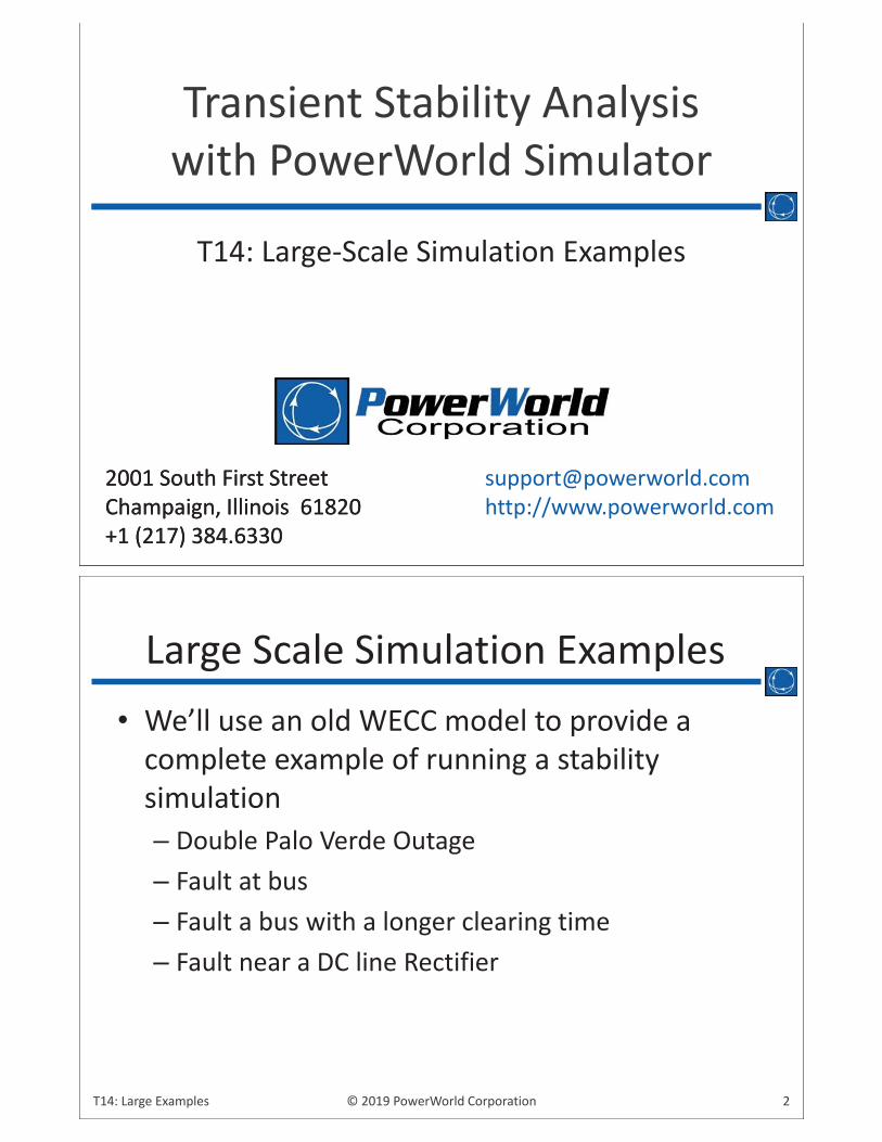
Transient Stability Analysis with PowerWorld Simulator
T14: Large-Scale Simulation Examples
2© 2019 PowerWorld CorporationT14: Large Examples
• We’ll use an old WECC model to provide a complete example of running a stability simulation– Double Palo Verde Outage– Fault at bus– Fault a bus with a longer clearing time– Fault near a DC line Rectifier
Large Scale Simulation Examples
3© 2019 PowerWorld CorporationT14: Large Examples
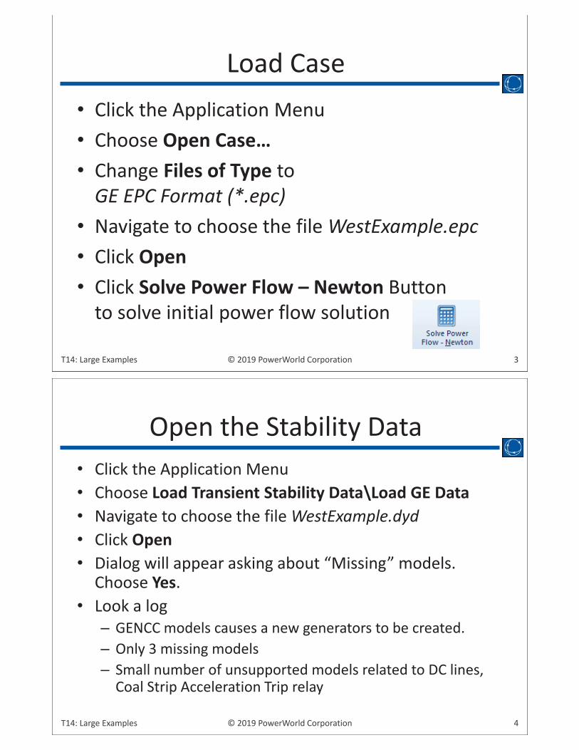
• Click the Application Menu• Choose Open Case…• Change Files of Type to
GE EPC Format (*.epc)• Navigate to choose the file WestExample.epc• Click Open• Click Solve Power Flow – Newton Button
to solve initial power flow solution
Load Case
4© 2019 PowerWorld CorporationT14: Large Examples
• Click the Application Menu• Choose Load Transient Stability Data\Load GE Data• Navigate to choose the file WestExample.dyd• Click Open• Dialog will appear asking about “Missing” models.
Choose Yes.• Look a log
– GENCC models causes a new generators to be created.– Only 3 missing models– Small number of unsupported models related to DC lines,
Coal Strip Acceleration Trip relay
Open the Stability Data
5© 2019 PowerWorld CorporationT14: Large Examples
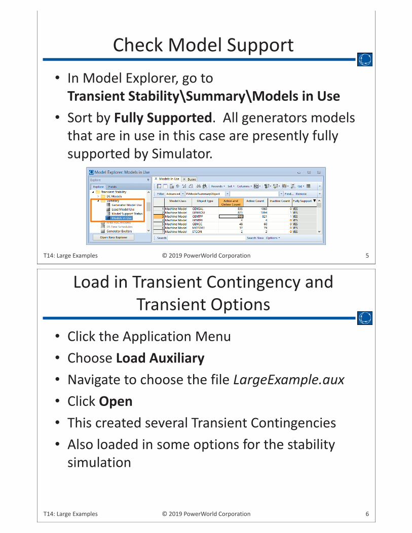
• In Model Explorer, go to Transient Stability\Summary\Models in Use
• Sort by Fully Supported. All generators models that are in use in this case are presently fully supported by Simulator.
Check Model Support
6© 2019 PowerWorld CorporationT14: Large Examples
• Click the Application Menu• Choose Load Auxiliary• Navigate to choose the file LargeExample.aux• Click Open• This created several Transient Contingencies• Also loaded in some options for the stability
simulation
Load in Transient Contingency and Transient Options
7© 2019 PowerWorld CorporationT14: Large Examples
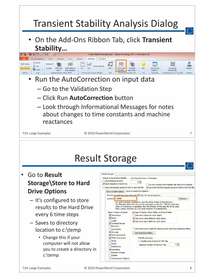
• On the Add-Ons Ribbon Tab, click Transient Stability…
• Run the AutoCorrection on input data– Go to the Validation Step– Click Run AutoCorrection button– Look through Informational Messages for notes
about changes to time constants and machine reactances
Transient Stability Analysis Dialog
8© 2019 PowerWorld CorporationT14: Large Examples
• Go to Result Storage\Store to Hard Drive Options– It’s configured to store
results to the Hard Drive every 6 time steps
– Saves to directory location to c:\temp
• Change this if your computer will not allow you to create a directory in c:\temp
Result Storage
9© 2019 PowerWorld CorporationT14: Large Examples
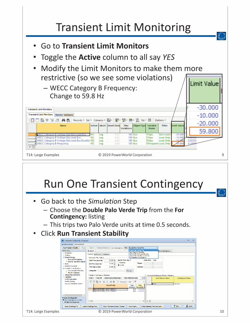
• Go to Transient Limit Monitors• Toggle the Active column to all say YES• Modify the Limit Monitors to make them more
restrictive (so we see some violations)– WECC Category B Frequency:
Change to 59.8 Hz
Transient Limit Monitoring
10© 2019 PowerWorld CorporationT14: Large Examples
• Go back to the Simulation Step– Choose the Double Palo Verde Trip from the For
Contingency: listing– This trips two Palo Verde units at time 0.5 seconds.
• Click Run Transient Stability
Run One Transient Contingency
11© 2019 PowerWorld CorporationT14: Large Examples
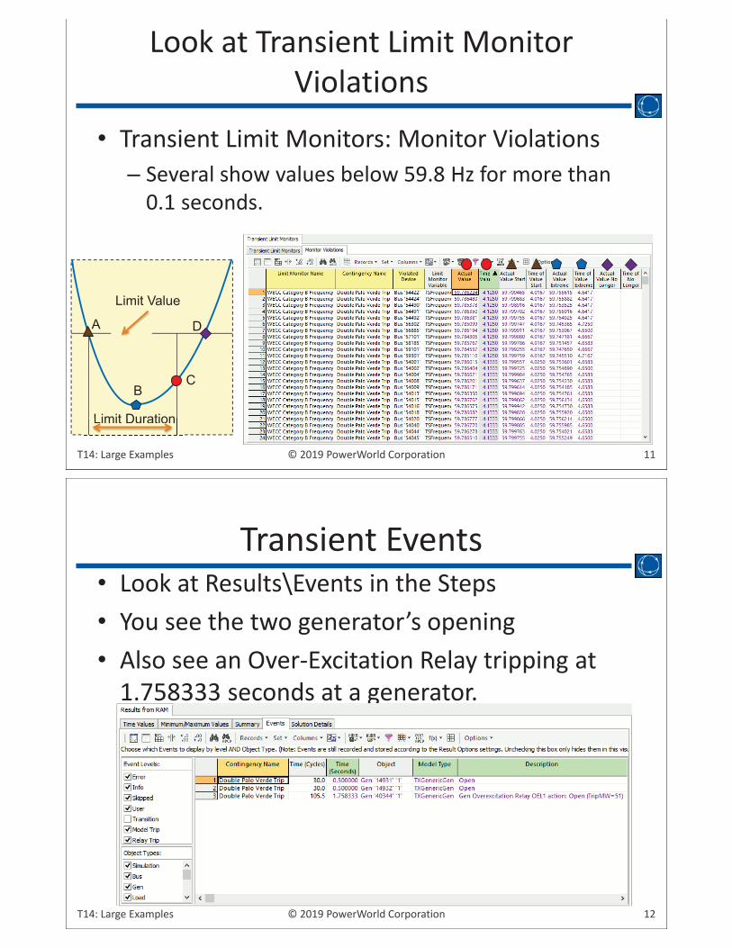
• Transient Limit Monitors: Monitor Violations– Several show values below 59.8 Hz for more than
0.1 seconds.
Look at Transient Limit Monitor Violations
A
BC
D
Limit Duration
Limit Value
Limit Duration
12© 2019 PowerWorld CorporationT14: Large Examples
• Look at Results\Events in the Steps• You see the two generator’s opening• Also see an Over-Excitation Relay tripping at
1.758333 seconds at a generator.
Transient Events
g
13© 2019 PowerWorld CorporationT14: Large Examples
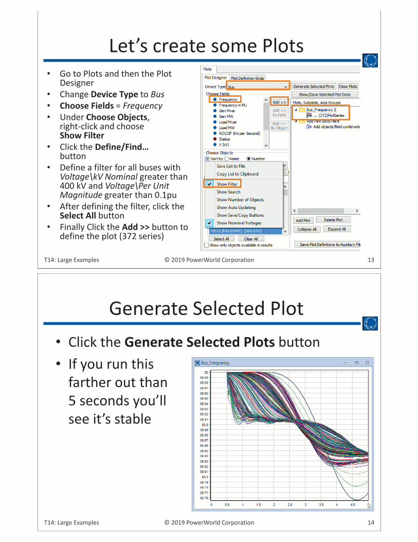
• Go to Plots and then the Plot Designer
• Change Device Type to Bus• Choose Fields = Frequency• Under Choose Objects,
right-click and choose Show Filter
• Click the Define/Find… button
• Define a filter for all buses with Voltage\kV Nominal greater than 400 kV and Voltage\Per Unit Magnitude greater than 0.1pu
• After defining the filter, click the Select All button
• Finally Click the Add >> button to define the plot (372 series)
Let’s create some Plots
14© 2019 PowerWorld CorporationT14: Large Examples
• Click the Generate Selected Plots button• If you run this
farther out than 5 seconds you’ll see it’s stable
Generate Selected Plot
15© 2019 PowerWorld CorporationT14: Large Examples
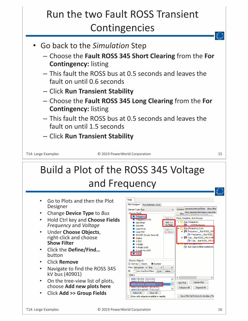
• Go back to the Simulation Step– Choose the Fault ROSS 345 Short Clearing from the For
Contingency: listing– This fault the ROSS bus at 0.5 seconds and leaves the
fault on until 0.6 seconds– Click Run Transient Stability– Choose the Fault ROSS 345 Long Clearing from the For
Contingency: listing– This fault the ROSS bus at 0.5 seconds and leaves the
fault on until 1.5 seconds– Click Run Transient Stability
Run the two Fault ROSS Transient Contingencies
16© 2019 PowerWorld CorporationT14: Large Examples
• Go to Plots and then the Plot Designer
• Change Device Type to Bus• Hold Ctrl key and Choose Fields
Frequency and Voltage• Under Choose Objects,
right-click and choose Show Filter
• Click the Define/Find… button
• Click Remove• Navigate to find the ROSS 345
kV bus (40901)• On the tree-view list of plots,
choose Add new plots here• Click Add >> Group Fields
Build a Plot of the ROSS 345 Voltage and Frequency
17© 2019 PowerWorld CorporationT14: Large Examples
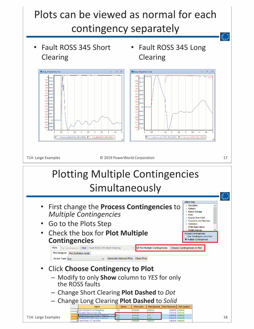
• Fault ROSS 345 Short Clearing
• Fault ROSS 345 Long Clearing
Plots can be viewed as normal for each contingency separately
18© 2019 PowerWorld CorporationT14: Large Examples ©©©©©©©©©©©©©©©©©©©©©©©©©©©©©©©©©©©©©©©©©©©©©©© 202020202020002000200020020020220000202020200000202202020000000191919 PoPoPooooooooooooooooooooooooooooowewewwwwwwwwwwwwwwwwwwwwwwwwwwwwwwwwwwwwwwwwwwwwwwwwwwwwwwwwwwwww rWrWrWororldldlddddddddddddddddddddddddddldddddddddddddddddddd CoCoCoCCoCCCCoCoCoCCoCoCCoCoCoCoCoCoCCoCoCoCCoCoCoCoCoCoCoCCoCCoCoCoCCCCCooCCCCCCCCCoCCCCCCCCoCCCoCCCCCoCoorprpororatatatatatatatattttatattatttattataatatattataataataaataaattttatttatttttaatttioioiioioiioioioioioioooioioioioioioioioiiooooooooooooooooooonn
• First change the Process Contingencies to Multiple Contingencies
• Go to the Plots Step• Check the box for Plot Multiple
Contingencies
• Click Choose Contingency to Plot– Modify to only Show column to YES for only
the ROSS faults– Change Short Clearing Plot Dashed to Dot– Change Long Clearing Plot Dashed to Solid
Plotting Multiple Contingencies Simultaneously
19© 2019 PowerWorld CorporationT14: Large Examples
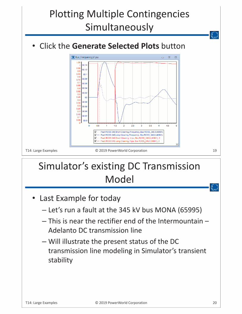
• Click the Generate Selected Plots button
Plotting Multiple Contingencies Simultaneously
20© 2019 PowerWorld CorporationT14: Large Examples
• Last Example for today– Let’s run a fault at the 345 kV bus MONA (65995) – This is near the rectifier end of the Intermountain –
Adelanto DC transmission line– Will illustrate the present status of the DC
transmission line modeling in Simulator’s transient stability
Simulator’s existing DC Transmission Model
21© 2019 PowerWorld CorporationT14: Large Examples
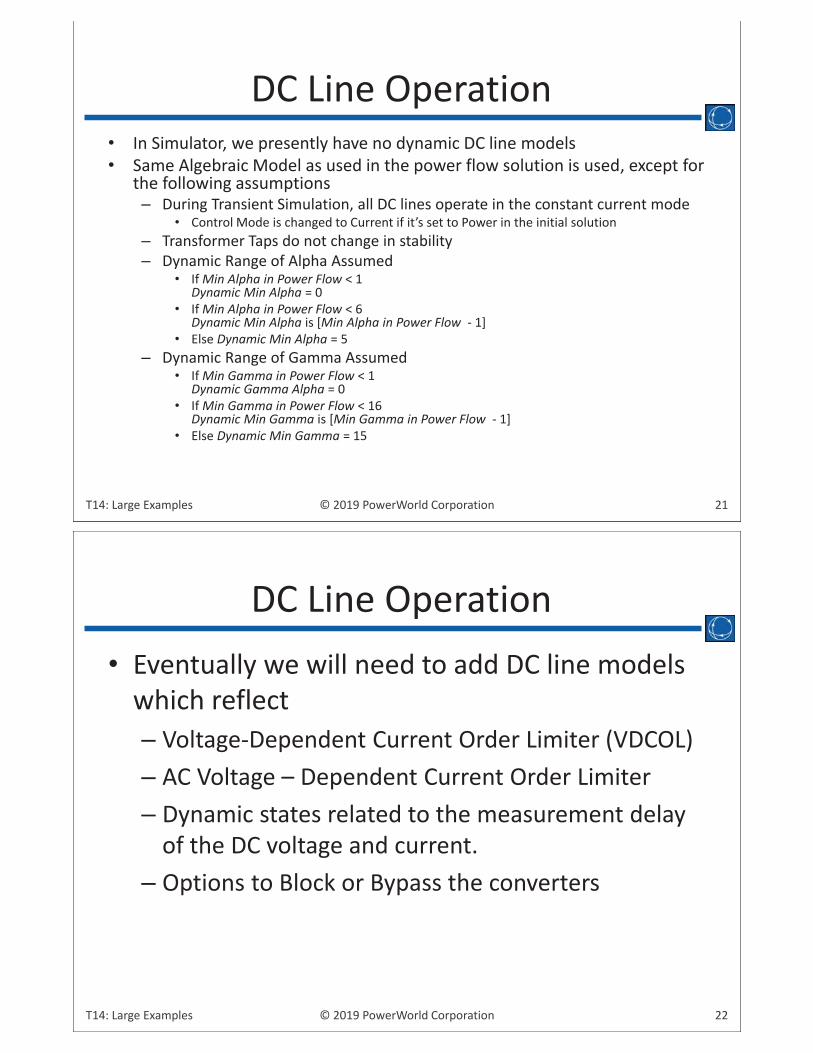
• In Simulator, we presently have no dynamic DC line models• Same Algebraic Model as used in the power flow solution is used, except for
the following assumptions– During Transient Simulation, all DC lines operate in the constant current mode
• Control Mode is changed to Current if it’s set to Power in the initial solution– Transformer Taps do not change in stability– Dynamic Range of Alpha Assumed
• If Min Alpha in Power Flow < 1Dynamic Min Alpha = 0
• If Min Alpha in Power Flow < 6 Dynamic Min Alpha is [Min Alpha in Power Flow - 1]
• Else Dynamic Min Alpha = 5– Dynamic Range of Gamma Assumed
• If Min Gamma in Power Flow < 1Dynamic Gamma Alpha = 0
• If Min Gamma in Power Flow < 16 Dynamic Min Gamma is [Min Gamma in Power Flow - 1]
• Else Dynamic Min Gamma = 15
DC Line Operation
22© 2019 PowerWorld CorporationT14: Large Examples
• Eventually we will need to add DC line models which reflect– Voltage-Dependent Current Order Limiter (VDCOL)– AC Voltage – Dependent Current Order Limiter– Dynamic states related to the measurement delay
of the DC voltage and current.– Options to Block or Bypass the converters
DC Line Operation
23© 2019 PowerWorld CorporationT14: Large Examples
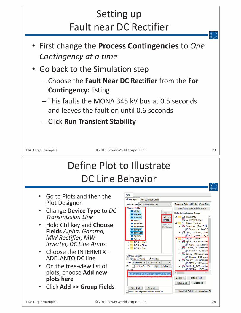
• First change the Process Contingencies to One Contingency at a time
• Go back to the Simulation step– Choose the Fault Near DC Rectifier from the For
Contingency: listing– This faults the MONA 345 kV bus at 0.5 seconds
and leaves the fault on until 0.6 seconds– Click Run Transient Stability
Setting up Fault near DC Rectifier
24© 2019 PowerWorld CorporationT14: Large Examples
• Go to Plots and then the Plot Designer
• Change Device Type to DC Transmission Line
• Hold Ctrl key and Choose Fields Alpha, Gamma, MW Rectifier, MW Inverter, DC Line Amps
• Choose the INTERMTX –ADELANTO DC line
• On the tree-view list of plots, choose Add new plots here
• Click Add >> Group Fields
Define Plot to IllustrateDC Line Behavior
25© 2019 PowerWorld CorporationT14: Large Examples
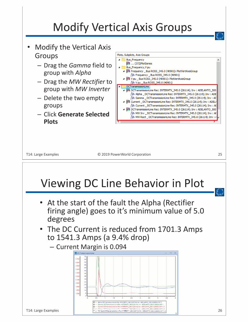
• Modify the Vertical Axis Groups– Drag the Gamma field to
group with Alpha– Drag the MW Rectifier to
group with MW Inverter– Delete the two empty
groups– Click Generate Selected
Plots
Modify Vertical Axis Groups
26© 2019 PowerWorld CorporationT14: Large Examples ©©©©©©©©©©©©©©©©©©©©©©©©©©©©©©©©©©©©©©©©©©©©©©©©©©©©©©©©©©©©©©©©©©©©©©©©©©©©©©©©©©©©©©©©©©©©©©©©©©©©©©©©©©©©©©©©©©©©©©©©©©©©©©©©©©©©©©©©©©©© 20202002022222020000000022222000002200202020200020200020220202022202000000220220202020200220222220202202002222222000022222222220000000001919191919191999111911999991919191111191919191911919191191119119111119119191999999191999911119999199991999919999919999911199999999119 PoPoPoPoPoPoPoPoPPPPPPPPoPoPPoPoPoPPPPoPPoPoPooooPoPPPPoPPPoPPooooooPPoPoPoPoPooPooPPoPooPoPPoPoooPoPPoooooPoPPowewewewewewwewewewewweeewewwwewwwewewewwwwewwwewewewewwwweeeeeewwwweeeewweeeeeeeeeeeeeeewwwwww rWrWrWrWrWWWrWWWWrWWWrWWWWWWWWrWWWWWWWrWrWrWWWrWWWWrWrWrWrrWWWWWWWrWrWrrrWrWrrWrWrWWWrWWWWWWrrWWrWWWrWrWrrrWrWWWWrrWrrWrrrrWrWWWrrrrrWWWWWWWrrWWWWrrrWorororooorooorrrrrororooooorororrrrrrrroororrrrorrrrrrrrrrrrrorrorrrrooorroorrooorroorrooooorrrrlddddldddddlllldddddddldllddllddldlddddddldlddddddldlddddddddddddddddddddddddddddddddddd CoCCoCoCCoCCCoCoCCCCCCCoCCCCCoCCCCCCCCCCoCCoCoCoCCoCooooCoCooCooCCCCCoCCCCCoCooooooooooCCCoCCoCCooooCoCooooooCCooCoooCCCCCoooCoooCCCoCoCoooCCCCCCCooCoCCCCCoooCCCCCoCoCCCooooorprprrrprppppppprprrrppprrrrrpppppprprrrpppprpppprpppprpppprppppppppppppprpppporororororoooooooororororororooooooroooooooooooorrrooooororoo taatatataataaaaataatatatatataaaaatatatattaaaaaaataaaaataaaaaatataaaaaaaaaaaaaaaatttaaaattttioioiooiioioiiioiioioioooooooooioooooooioooiooooooioiooooooiioooiioiioooooioiioooooiiooooooiioooiiooooonnnnnnnnnnnnnnnnnnnnnnnnnnnnnnnnnnnnnnnnnnnnnn
• At the start of the fault the Alpha (Rectifier firing angle) goes to it’s minimum value of 5.0 degrees
• The DC Current is reduced from 1701.3 Amps to 1541.3 Amps (a 9.4% drop)– Current Margin is 0.094
Viewing DC Line Behavior in Plot
27© 2019 PowerWorld CorporationT14: Large Examples
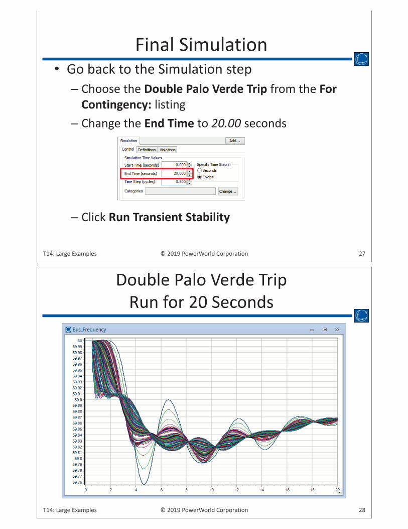
Final Simulation• Go back to the Simulation step
– Choose the Double Palo Verde Trip from the For Contingency: listing
– Change the End Time to 20.00 seconds
– Click Run Transient Stability
28© 2019 PowerWorld CorporationT14: Large Examples
Double Palo Verde Trip Run for 20 Seconds