Embed Size (px)
Citation preview

13
Surface Mount Transient Voltage Suppressors (TVS) SMF Series 5.0 To 190 V 200W
Uni-directional Bi-directional
Compatible with industrial standard package SOD-123 For surface mounted applications in order to optimize board
space Low leakage Uni and Bidirectional unit Glass passivated junction Low inductance Excellent clamping capability 200W Peak power capability at 10 × 1000µs waveform
Repetition rate (duty cycle):0.01% Fast response time: typically less than 1.0ps from 0 Volts to
VBR min High Temperature soldering: 260°C/40 seconds at terminals Typical maximum temperature coefficient ΔVBR = 0.1% ×
VBR@25°C× ΔT Plastic package has Underwriters Laboratory Flammability
94V-0 Matte tin lead–free Plated Halogen free and RoHS compliant Typical failure mode is short from over-specified voltage or
current Whisker test is conducted based on JEDEC JESD201A per its
table 4a and 4c IEC-61000-4-2 ESD 15kV(Air), 8kV (Contact) ESD protection of data lines in accordance with IEC 61000-4-2
(IEC801-2) EFT protection of data lines in accordance with IEC 61000-4-4
(IEC801-4)
SOD-123
DimensionsInches Millimeters
Min Max Min Max
A 0.031 0.044 0.77 1.09
B 0.1 0.112 2.51 2.81
C 0.055 0.071 1.38 1.78
D 0.140 0.152 3.51 3.82
E 0.037 0.053 0.93 1.33
F 0.01 - 0.25 -
G - 0.008 - 0.20
Dimensions
SOD-123
Cathode Band
Features
www.amstron.es +34912177859 [email protected]

14
Surface Mount Transient Voltage Suppressors (TVS) SMF Series 5.0 To 190 V 200W
Part Number MarkingReverseStand-OffVoltageVRWM(V)
BreakdownVoltage VBR (V)
@IT
TestCurrent
IT(mA)
MaximumClampingVoltageVC
@IPP (V)
MaximumPeakPulseCurrentIPP (A)
MaximumReverseLeakage IR@VRWM(μA)Uni Bi Uni Bi MIN MAX
SMF5.0A SMF5.0CA FE KE 5.0 6.40 7.00 10 9.2 21.74 400SMF6.0A SMF6.0CA FG KG 6.0 6.67 7.37 10 10.3 19.42 400SMF6.5A SMF6.5CA FK KK 6.5 7.22 7.98 10 11.2 17.86 250SMF7.0A SMF7.0CA FM KM 7.0 7.78 8.60 10 12.0 16.67 100SMF7.5A SMF7.5CA FP KP 7.5 8.33 9.21 1 12.9 15.50 50SMF8.0A SMF8.0CA FR KR 8.0 8.89 9.83 1 13.6 14.71 25SMF8.5A SMF8.5CA FT KT 8.5 9.44 10.40 1 14.4 13.89 10SMF9.0A SMF9.0CA FV KV 9.0 10.00 11.10 1 15.4 12.99 5SMF10A SMF10CA FX KX 10.0 11.10 12.30 1 17.0 11.76 2.5SMF11A SMF11CA FZ KZ 11.0 12.20 13.50 1 18.2 10.99 2.5SMF12A SMF12CA HE LE 12.0 13.30 14.70 1 19.9 10.05 2.5SMF13A SMF13CA HG LG 13.0 14.40 15.90 1 21.5 9.30 1SMF14A SMF14CA HK LK 14.0 15.60 17.20 1 23.2 8.62 1SMF15A SMF15CA HM LM 15.0 16.70 18.50 1 24.4 8.20 1SMF16A SMF16CA HP LP 16.0 17.80 19.70 1 26.0 7.69 1SMF17A SMF17CA HR LR 17.0 18.90 20.90 1 27.6 7.25 1SMF18A SMF18CA HT LT 18.0 20.00 22.10 1 29.2 6.85 1SMF19A SMF19CA HB LB 19.0 21.10 23.30 1 30.6 6.54 1SMF20A SMF20CA HV LV 20.0 22.20 24.50 1 32.4 6.17 1SMF22A SMF22CA HX LX 22.0 24.40 26.90 1 35.5 5.63 1SMF24A SMF24CA HZ LZ 24.0 26.70 29.50 1 38.9 5.14 1SMF26A SMF26CA JE ME 26.0 28.90 31.90 1 42.1 4.75 1SMF28A SMF28CA JG MG 28.0 31.10 34.40 1 45.4 4.41 1SMF30A SMF30CA JK MK 30.0 33.30 36.80 1 48.4 4.13 1SMF33A SMF33CA JM MM 33.0 36.70 40.60 1 53.3 3.75 1SMF36A SMF36CA JP MP 36.0 40.00 44.20 1 58.1 3.44 1SMF40A SMF40CA JR MR 40.0 44.40 49.10 1 64.5 3.10 1SMF43A SMF43CA JT MT 43.0 47.80 52.80 1 69.4 2.88 1SMF45A SMF45CA JV MV 45.0 50.00 55.30 1 72.7 2.75 1SMF48A SMF48CA JX MX 48.0 53.30 58.90 1 77.4 2.58 1SMF51A SMF51CA JZ MZ 51.0 56.70 62.70 1 82.4 2.43 1SMF54A SMF54CA XE NE 54.0 60.00 66.30 1 87.1 2.30 1SMF58A SMF58CA XG NG 58.0 64.40 71.20 1 93.6 2.14 1SMF60A SMF60CA XK NK 60.0 66.70 73.70 1 96.8 2.07 1SMF64A SMF64CA XM NM 64.0 71.10 78.60 1 103.0 1.94 1SMF70A SMF70CA XP NP 70.0 77.80 86.00 1 113.0 1.77 1SMF75A SMF75CA XR NR 75.0 83.30 92.10 1 121.0 1.65 1SMF78A SMF78CA XT NT 78.0 86.70 95.80 1 126.0 1.59 1SMF80A SMF80CA XB NB 80.0 88.80 97.60 1 129.0 1.55 1SMF85A SMF85CA XV NV 85.0 94.40 104.00 1 137.0 1.46 1SMF90A SMF90CA XX NX 90.0 100.00 111.00 1 146.0 1.37 1SMF100A SMF100CA XZ NZ 100.0 111.00 123.00 1 162.0 1.23 1SMF110A SMF110CA TE PE 110.0 122.00 135.00 1 177.0 1.13 1SMF120A SMF120CA TG PG 120.0 133.00 147.00 1 193.0 1.04 1SMF130A SMF130CA TK PK 130.0 144.00 159.00 1 209.0 0.96 1SMF140A SMF140CA TB PB 140.0 155.00 171.00 1 224.0 0.89 1SMF150A SMF150CA TM PM 150.0 167.00 185.00 1 243.0 0.82 1SMF160A SMF160CA TP PP 160.0 178.00 197.00 1 259.0 0.77 1SMF170A SMF170CA TR PR 170.0 189.00 209.00 1 275.0 0.73 1SMF180A SMF180CA TT PT 180.0 200.00 220.00 1 292.0 0.69 1
Note:1. Suffix 'A ' denotes 5% tolerance device. Without 'A' denotes 10% tolerance device2. Add suffix 'C 'or ' CA ' after part number to specify Bi-directional devices3. For Bi-Directional devices having VR of 10 volts and under, the IR limit is double
Electrical Characteristics (TA=25℃ unless otherwise noted)
www.amstron.es +34912177859 [email protected]

15
Surface Mount Transient Voltage Suppressors (TVS) SMAJ Series 5.0 To 440 V 400W
Uni-directional Bi-directional
For surface mounted applications in order to optimize boardspace
Low leakage Uni and Bidirectional unit Glass passivated junction Low inductance Excellent clamping capability 400W Peak power capability at 10 × 1000µs waveform
Repetition rate (duty cycle):0.01% Fast response time: typically less than 1.0ps from 0 Volts to
VBR min Typical IR less than 5μA above 12V High Temperature soldering: 260°C/40 seconds at terminals Typical maximum temperature coefficient ΔVBR = 0.1% ×
VBR@25°C× ΔT Plastic package has Underwriters Laboratory Flammability
94V-0 Matte tin lead–free Plated Halogen free and RoHS compliant Typical failure mode is short from over-specified voltage or
current Whisker test is conducted based on JEDEC JESD201A per its
table 4a and 4c IEC-61000-4-2 ESD 15kV(Air), 8kV (Contact) ESD protection of data lines in accordance with IEC 61000-4-2
(IEC801-2) EFT protection of data lines in accordance with IEC 61000-4-4
(IEC801-4)
DO-214AC / SMA
DimensionsInches Millimeters
Min Max Min Max
A 0.049 0.064 1.230 1.630
B 0.162 0.179 4.10 4.550
C 0.099 0.109 2.510 2.760
D 0.077 0.089 1.960 2.260
E 0.030 0.060 0.750 1.510
F - 0.008 - 0.203
G 0.192 0.206 4.87 5.220
H 0.006 0.012 0.152 0.305
I 0.070 - 1.800 -
J 0.082 - 2.100 -
K - 0.090 - 2.300
L 0.082 - 2.100 -
Features
Dimensions
DO-214AC (SMA)
Cathode Band
www.amstron.es +34912177859 [email protected]
16
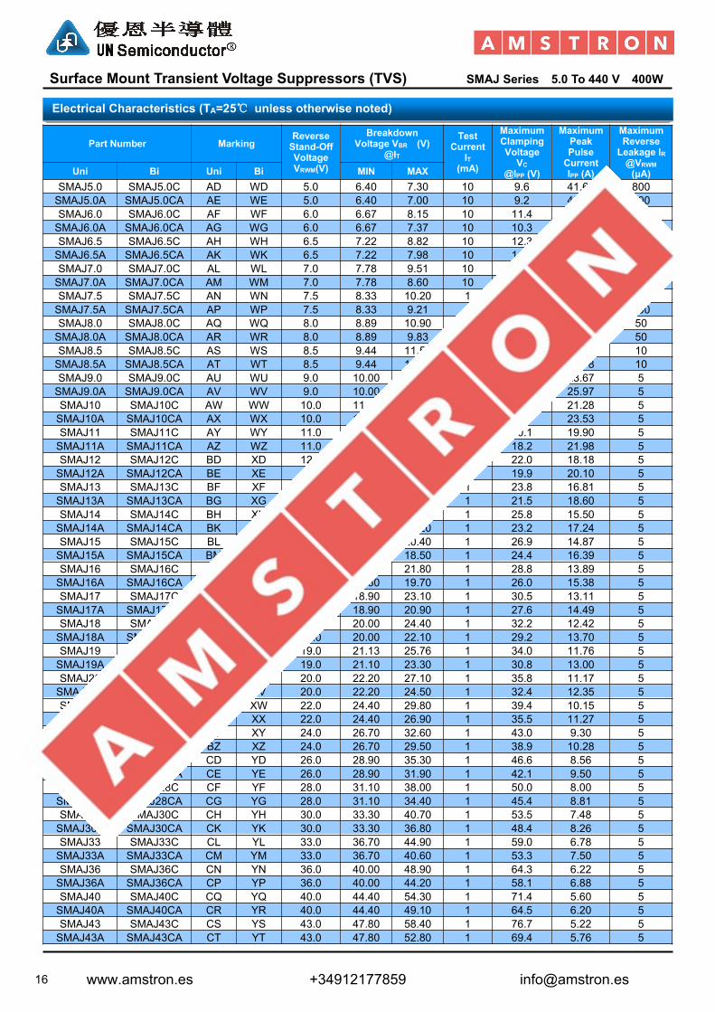
Surface Mount Transient Voltage Suppressors (TVS) SMAJ Series 5.0 To 440 V 400W
Part Number MarkingReverseStand-OffVoltageVRWM(V)
BreakdownVoltage VBR (V)
@IT
TestCurrent
IT(mA)
MaximumClampingVoltageVC
@IPP (V)
MaximumPeakPulseCurrentIPP (A)
MaximumReverseLeakage IR@VRWM(μA)Uni Bi Uni Bi MIN MAX
SMAJ5.0 SMAJ5.0C AD WD 5.0 6.40 7.30 10 9.6 41.67 800SMAJ5.0A SMAJ5.0CA AE WE 5.0 6.40 7.00 10 9.2 43.48 800SMAJ6.0 SMAJ6.0C AF WF 6.0 6.67 8.15 10 11.4 35.09 800SMAJ6.0A SMAJ6.0CA AG WG 6.0 6.67 7.37 10 10.3 38.83 800SMAJ6.5 SMAJ6.5C AH WH 6.5 7.22 8.82 10 12.3 32.52 500SMAJ6.5A SMAJ6.5CA AK WK 6.5 7.22 7.98 10 11.2 35.71 500SMAJ7.0 SMAJ7.0C AL WL 7.0 7.78 9.51 10 13.3 30.08 200SMAJ7.0A SMAJ7.0CA AM WM 7.0 7.78 8.60 10 12.0 33.33 200SMAJ7.5 SMAJ7.5C AN WN 7.5 8.33 10.20 1 14.3 27.97 100SMAJ7.5A SMAJ7.5CA AP WP 7.5 8.33 9.21 1 12.9 31.01 100SMAJ8.0 SMAJ8.0C AQ WQ 8.0 8.89 10.90 1 15.0 26.67 50SMAJ8.0A SMAJ8.0CA AR WR 8.0 8.89 9.83 1 13.6 29.41 50SMAJ8.5 SMAJ8.5C AS WS 8.5 9.44 11.50 1 15.9 25.16 10SMAJ8.5A SMAJ8.5CA AT WT 8.5 9.44 10.40 1 14.4 27.78 10SMAJ9.0 SMAJ9.0C AU WU 9.0 10.00 12.20 1 16.9 23.67 5SMAJ9.0A SMAJ9.0CA AV WV 9.0 10.00 11.10 1 15.4 25.97 5SMAJ10 SMAJ10C AW WW 10.0 11.10 13.60 1 18.8 21.28 5SMAJ10A SMAJ10CA AX WX 10.0 11.10 12.30 1 17.0 23.53 5SMAJ11 SMAJ11C AY WY 11.0 12.20 14.90 1 20.1 19.90 5SMAJ11A SMAJ11CA AZ WZ 11.0 12.20 13.50 1 18.2 21.98 5SMAJ12 SMAJ12C BD XD 12.0 13.30 16.30 1 22.0 18.18 5SMAJ12A SMAJ12CA BE XE 12.0 13.30 14.70 1 19.9 20.10 5SMAJ13 SMAJ13C BF XF 13.0 14.40 17.60 1 23.8 16.81 5SMAJ13A SMAJ13CA BG XG 13.0 14.40 15.90 1 21.5 18.60 5SMAJ14 SMAJ14C BH XH 14.0 15.60 19.10 1 25.8 15.50 5SMAJ14A SMAJ14CA BK XK 14.0 15.60 17.20 1 23.2 17.24 5SMAJ15 SMAJ15C BL XL 15.0 16.70 20.40 1 26.9 14.87 5SMAJ15A SMAJ15CA BM XM 15.0 16.70 18.50 1 24.4 16.39 5SMAJ16 SMAJ16C BN XN 16.0 17.80 21.80 1 28.8 13.89 5SMAJ16A SMAJ16CA BP XP 16.0 17.80 19.70 1 26.0 15.38 5SMAJ17 SMAJ17C BQ XQ 17.0 18.90 23.10 1 30.5 13.11 5SMAJ17A SMAJ17CA BR XR 17.0 18.90 20.90 1 27.6 14.49 5SMAJ18 SMAJ18C BS XS 18.0 20.00 24.40 1 32.2 12.42 5SMAJ18A SMAJ18CA BT XT 18.0 20.00 22.10 1 29.2 13.70 5SMAJ19 SMAJ19C BA XA 19.0 21.13 25.76 1 34.0 11.76 5SMAJ19A SMAJ19CA BB XB 19.0 21.10 23.30 1 30.8 13.00 5SMAJ20 SMAJ20C BU XU 20.0 22.20 27.10 1 35.8 11.17 5SMAJ20A SMAJ20CA BV XV 20.0 22.20 24.50 1 32.4 12.35 5SMAJ22 SMAJ22C BW XW 22.0 24.40 29.80 1 39.4 10.15 5SMAJ22A SMAJ22CA BX XX 22.0 24.40 26.90 1 35.5 11.27 5SMAJ24 SMAJ24C BY XY 24.0 26.70 32.60 1 43.0 9.30 5SMAJ24A SMAJ24CA BZ XZ 24.0 26.70 29.50 1 38.9 10.28 5SMAJ26 SMAJ26C CD YD 26.0 28.90 35.30 1 46.6 8.56 5SMAJ26A SMAJ26CA CE YE 26.0 28.90 31.90 1 42.1 9.50 5SMAJ28 SMAJ28C CF YF 28.0 31.10 38.00 1 50.0 8.00 5SMAJ28A SMAJ28CA CG YG 28.0 31.10 34.40 1 45.4 8.81 5SMAJ30 SMAJ30C CH YH 30.0 33.30 40.70 1 53.5 7.48 5SMAJ30A SMAJ30CA CK YK 30.0 33.30 36.80 1 48.4 8.26 5SMAJ33 SMAJ33C CL YL 33.0 36.70 44.90 1 59.0 6.78 5SMAJ33A SMAJ33CA CM YM 33.0 36.70 40.60 1 53.3 7.50 5SMAJ36 SMAJ36C CN YN 36.0 40.00 48.90 1 64.3 6.22 5SMAJ36A SMAJ36CA CP YP 36.0 40.00 44.20 1 58.1 6.88 5SMAJ40 SMAJ40C CQ YQ 40.0 44.40 54.30 1 71.4 5.60 5SMAJ40A SMAJ40CA CR YR 40.0 44.40 49.10 1 64.5 6.20 5SMAJ43 SMAJ43C CS YS 43.0 47.80 58.40 1 76.7 5.22 5SMAJ43A SMAJ43CA CT YT 43.0 47.80 52.80 1 69.4 5.76 5
Electrical Characteristics (TA=25℃ unless otherwise noted)
www.amstron.es +34912177859 [email protected]

17
Surface Mount Transient Voltage Suppressors (TVS) SMAJ Series 5.0 To 440 V 400W
Part Number MarkingReverseStand-OffVoltageVRWM(V)
BreakdownVoltage VBR (V)
@IT
TestCurrent
IT(mA)
MaximumClampingVoltageVC
@IPP (V)
MaximumPeakPulseCurrentIPP (A)
MaximumReverseLeakage IR@VRWM(μA)Uni Bi Uni Bi MIN MAX
SMAJ45 SMAJ45C CU YU 45.0 50.00 61.10 1 80.3 4.98 5SMAJ45A SMAJ45CA CV YV 45.0 50.00 55.30 1 72.7 5.50 5SMAJ48 SMAJ48C CW YW 48.0 53.30 65.10 1 85.5 4.68 5SMAJ48A SMAJ48CA CX YX 48.0 53.30 58.90 1 77.4 5.17 5SMAJ51 SMAJ51C CY YY 51.0 56.70 69.30 1 91.1 4.39 5SMAJ51A SMAJ51CA CZ YZ 51.0 56.70 62.70 1 82.4 4.85 5SMAJ54 SMAJ54C RD ZD 54.0 60.00 73.30 1 96.3 4.15 5SMAJ54A SMAJ54CA RE ZE 54.0 60.00 66.30 1 87.1 4.59 5SMAJ58 SMAJ58C RF ZF 58.0 64.40 78.70 1 103.0 3.88 5SMAJ58A SMAJ58CA RG ZG 58.0 64.40 71.20 1 93.6 4.27 5SMAJ60 SMAJ60C RH ZH 60.0 66.70 81.50 1 107.0 3.74 5SMAJ60A SMAJ60CA RK ZK 60.0 66.70 73.70 1 96.8 4.13 5SMAJ64 SMAJ64C RL ZL 64.0 71.10 86.90 1 114.0 3.51 5SMAJ64A SMAJ64CA RM ZM 64.0 71.10 78.60 1 103.0 3.88 5SMAJ70 SMAJ70C RN ZN 70.0 77.80 95.10 1 125.0 3.20 5SMAJ70A SMAJ70CA RP ZP 70.0 77.80 86.00 1 113.0 3.54 5SMAJ75 SMAJ75C RQ ZQ 75.0 83.30 102.00 1 134.0 2.99 5SMAJ75A SMAJ75CA RR ZR 75.0 83.30 92.10 1 121.0 3.31 5SMAJ78 SMAJ78C RS ZS 78.0 86.70 106.00 1 139.0 2.88 5SMAJ78A SMAJ78CA RT ZT 78.0 86.70 95.80 1 126.0 3.17 5SMAJ80 SMAJ80C RA ZA 80.0 88.96 108.80 1 143.2 2.79 5SMAJ80A SMAJ80CA RB ZB 80.0 88.80 97.60 1 129.6 3.09 5SMAJ85 SMAJ85C RU ZU 85.0 94.40 115.00 1 151.0 2.65 5SMAJ85A SMAJ85CA RV ZV 85.0 94.40 104.00 1 137.0 2.92 5SMAJ90 SMAJ90C RW ZW 90.0 100.00 122.00 1 160.0 2.50 5SMAJ90A SMAJ90CA RX ZX 90.0 100.00 111.00 1 146.0 2.74 5SMAJ100 SMAJ100C RY ZY 100.0 111.00 136.00 1 179.0 2.23 5SMAJ100A SMAJ100CA RZ ZZ 100.0 111.00 123.00 1 162.0 2.47 5SMAJ110 SMAJ110C SD VD 110.0 122.00 149.00 1 196.0 2.04 5SMAJ110A SMAJ110CA SE VE 110.0 122.00 135.00 1 177.0 2.26 5SMAJ120 SMAJ120C SF VF 120.0 133.00 163.00 1 214.0 1.87 5SMAJ120A SMAJ120CA SG VG 120.0 133.00 147.00 1 193.0 2.07 5SMAJ130 SMAJ130C SH VH 130.0 144.00 176.00 1 231.0 1.73 5SMAJ130A SMAJ130CA SK VK 130.0 144.00 159.00 1 209.0 1.91 5SMAJ140 SMAJ140C SA VA 140.0 155.68 190.40 1 250.6 1.60 5SMAJ140A SMAJ140CA SB VB 140.0 155.00 171.00 1 226.8 1.76 5SMAJ150 SMAJ150C SL VL 150.0 167.00 204.00 1 268.0 1.49 5SMAJ150A SMAJ150CA SM VM 150.0 167.00 185.00 1 243.0 1.65 5SMAJ160 SMAJ160C SN VN 160.0 178.00 218.00 1 287.0 1.39 5SMAJ160A SMAJ160CA SP VP 160.0 178.00 197.00 1 259.0 1.54 5SMAJ170 SMAJ170C SQ VQ 170.0 189.00 231.00 1 304.0 1.32 5SMAJ170A SMAJ170CA SR VR 170.0 189.00 209.00 1 275.0 1.45 5SMAJ180 SMAJ180C SS VS 180.0 201.00 244.80 1 322.2 1.24 5SMAJ180A SMAJ180CA ST VT 180.0 201.00 220.00 1 291.6 1.37 5SMAJ190 SMAJ190C SU VU 190.0 211.21 258.40 1 340.1 1.18 5SMAJ190A SMAJ190CA SV VV 190.0 211.00 232.00 1 307.8 1.30 5SMAJ200A SMAJ200CA SW VW 200.0 224.00 247.00 1 324.0 1.23 5SMAJ220A SMAJ220CA SX VX 220.0 246.00 272.00 1 356.0 1.12 5SMAJ250A SMAJ250CA SZ VZ 250.0 279.00 309.00 1 405.0 0.99 5SMAJ300A SMAJ300CA DE HE 300.0 335.00 371.00 1 486.0 0.82 5SMAJ350A SMAJ350CA DG HG 350.0 391.00 432.00 1 567.0 0.71 5SMAJ400A SMAJ400CA DK HK 400.0 447.00 494.00 1 648.0 0.62 5SMAJ440A SMAJ440CA DM HM 440.0 492.00 543.00 1 713.0 0.56 5
Note:1. Suffix 'A ' denotes 5% tolerance device. Without 'A' denotes 10% tolerance device2. Add suffix 'C 'or ' CA ' after part number to specify Bi-directional devices3. For Bi-Directional devices having VR of 10 volts and under, the IR limit is double
Electrical Characteristics (TA=25℃ unless otherwise noted)
www.amstron.es +34912177859 [email protected]

18
Surface Mount Transient Voltage Suppressors (TVS) SMBJ Series 5.0 To 440 V 600W
Uni-directional Bi-directional
For surface mounted applications in order to optimize boardspace
Low leakage Uni and Bidirectional unit Glass passivated junction Low inductance Excellent clamping capability 600W Peak power capability at 10 × 1000µs waveform
Repetition rate (duty cycle):0.01% Fast response time: typically less than 1.0ps from 0 Volts to
VBR min Typical IR less than 5μA above 12V. High Temperature soldering: 260°C/40 seconds at terminals Typical maximum temperature coefficient ΔVBR = 0.1% ×
VBR@25°C× ΔT Plastic package has Underwriters Laboratory Flammability
94V-0 Matte tin lead–free Plated Halogen free and RoHS compliant Typical failure mode is short from over-specified voltage or
current Whisker test is conducted based on JEDEC JESD201A per its
table 4a and 4c IEC-61000-4-2 ESD 15kV(Air), 8kV (Contact) ESD protection of data lines in accordance with IEC 61000-4-2
(IEC801-2) EFT protection of data lines in accordance with IEC 61000-4-4
(IEC801-4)
DO-214AA / SMB
DimensionsInches Millimeters
Min Max Min Max
A 0.077 0.087 1.960 2.200
B 0.171 0.191 4.350 4.850
C 0.130 0.155 3.300 3.940
D 0.084 0.096 2.130 2.440
E 0.030 0.060 0.750 1.520
F - 0.008 - 0.203
G 0.201 0.216 5.100 5.500
H 0.006 0.012 0.152 0.305
I 0.089 - 2.260 -
J 0.085 - 2.160 -
K - 0.107 - 2.740
L 0.085 - 2.160 -
Features
Dimensions
DO-214AA (SMB)
Cathode Band
www.amstron.es +34912177859 [email protected]

19
Surface Mount Transient Voltage Suppressors (TVS) SMBJ Series 5.0 To 440 V 600W
Part Number MarkingReverseStand-OffVoltageVRWM(V)
BreakdownVoltage VBR (V)
@IT
TestCurrent
IT(mA)
MaximumClampingVoltageVC
@IPP (V)
MaximumPeakPulseCurrentIPP (A)
MaximumReverseLeakage IR@VRWM(μA)Uni Bi Uni Bi MIN MAX
SMBJ5.0 SMBJ5.0C KD AD 5.0 6.40 7.30 10 9.6 62.50 800SMBJ5.0A SMBJ5.0CA KE AE 5.0 6.40 7.00 10 9.2 65.22 800SMBJ6.0 SMBJ6.0C KF AF 6.0 6.67 8.15 10 11.4 52.63 800SMBJ6.0A SMBJ6.0CA KG AG 6.0 6.67 7.37 10 10.3 58.25 800SMBJ6.5 SMBJ6.5C KH AH 6.5 7.22 8.82 10 12.3 48.78 500SMBJ6.5A SMBJ6.5CA KK AK 6.5 7.22 7.98 10 11.2 53.57 500SMBJ7.0 SMBJ7.0C KL AL 7.0 7.78 9.51 10 13.3 45.11 200SMBJ7.0A SMBJ7.0CA KM AM 7.0 7.78 8.60 10 12.0 50.00 200SMBJ7.5 SMBJ7.5C KN AN 7.5 8.33 10.20 1 14.3 41.96 100SMBJ7.5A SMBJ7.5CA KP AP 7.5 8.33 9.21 1 12.9 46.51 100SMBJ8.0 SMBJ8.0C KQ AQ 8.0 8.89 10.90 1 15.0 40.00 50SMBJ8.0A SMBJ8.0CA KR AR 8.0 8.89 9.83 1 13.6 44.12 50SMBJ8.5 SMBJ8.5C KS AS 8.5 9.44 11.50 1 15.9 37.74 10SMBJ8.5A SMBJ8.5CA KT AT 8.5 9.44 10.40 1 14.4 41.67 10SMBJ9.0 SMBJ9.0C KU AU 9.0 10.00 12.20 1 16.9 35.50 5SMBJ9.0A SMBJ9.0CA KV AV 9.0 10.00 11.10 1 15.4 38.96 5SMBJ10 SMBJ10C KW AA 10.0 11.10 13.60 1 18.8 31.91 5SMBJ10A SMBJ10CA KX AX 10.0 11.10 12.30 1 17.0 35.29 5SMBJ11 SMBJ11C KY AY 11.0 12.20 14.90 1 20.1 29.85 5SMBJ11A SMBJ11CA KZ WZ 11.0 12.20 13.50 1 18.2 32.97 5SMBJ12 SMBJ12C LD BD 12.0 13.30 16.30 1 22.0 27.27 5SMBJ12A SMBJ12CA LE BE 12.0 13.30 14.70 1 19.9 30.15 5SMBJ13 SMBJ13C LF BF 13.0 14.40 17.60 1 23.8 25.21 5SMBJ13A SMBJ13CA LG BG 13.0 14.40 15.90 1 21.5 27.91 5SMBJ14 SMBJ14C LH BH 14.0 15.60 19.10 1 25.8 23.26 5SMBJ14A SMBJ14CA LK BK 14.0 15.60 17.20 1 23.2 25.86 5SMBJ15 SMBJ15C LL BL 15.0 16.70 20.40 1 26.9 22.30 5SMBJ15A SMBJ15CA LM BM 15.0 16.70 18.50 1 24.4 24.59 5SMBJ16 SMBJ16C LN BN 16.0 17.80 21.80 1 28.8 20.83 5SMBJ16A SMBJ16CA LP BP 16.0 17.80 19.70 1 26.0 23.08 5SMBJ17 SMBJ17C LQ BQ 17.0 18.90 23.10 1 30.5 19.67 5SMBJ17A SMBJ17CA LR BR 17.0 18.90 20.90 1 27.6 21.74 5SMBJ18 SMBJ18C LS BS 18.0 20.00 24.40 1 32.2 18.63 5SMBJ18A SMBJ18CA LT BT 18.0 20.00 22.10 1 29.2 20.55 5SMBJ19 SMBJ19C LA BA 19.0 21.13 25.76 1 34.0 17.64 5SMBJ19A SMBJ19CA LB BB 19.0 21.10 23.30 1 30.8 19.49 5SMBJ20 SMBJ20C LU BU 20.0 22.20 27.10 1 35.8 16.67 5SMBJ20A SMBJ20CA LV BV 20.0 22.20 24.50 1 32.4 18.52 5SMBJ22 SMBJ22C LW BW 22.0 24.40 29.80 1 39.4 15.23 5SMBJ22A SMBJ22CA LX BX 22.0 24.40 26.90 1 35.5 16.90 5SMBJ24 SMBJ24C LY BY 24.0 26.70 32.60 1 43.0 13.95 5SMBJ24A SMBJ24CA LZ BZ 24.0 26.70 29.50 1 38.9 15.42 5SMBJ26 SMBJ26C MD CD 26.0 28.90 35.30 1 46.6 12.88 5SMBJ26A SMBJ26CA ME CE 26.0 28.90 31.90 1 42.1 14.25 5SMBJ28 SMBJ28C MF CF 28.0 31.10 38.00 1 50.0 12.00 5SMBJ28A SMBJ28CA MG CG 28.0 31.10 34.40 1 45.4 13.22 5SMBJ30 SMBJ30C MH CH 30.0 33.30 40.70 1 53.5 11.21 5SMBJ30A SMBJ30CA MK CK 30.0 33.30 36.80 1 48.4 12.40 5SMBJ33 SMBJ33C ML CL 33.0 36.70 44.90 1 59.0 10.17 5SMBJ33A SMBJ33CA MM CM 33.0 36.70 40.60 1 53.3 11.26 5SMBJ36 SMBJ36C MN CN 36.0 40.00 48.90 1 64.3 9.33 5SMBJ36A SMBJ36CA MP CP 36.0 40.00 44.20 1 58.1 10.33 5SMBJ40 SMBJ40C MQ CQ 40.0 44.40 54.30 1 71.4 8.40 5SMBJ40A SMBJ40CA MR CR 40.0 44.40 49.10 1 64.5 9.30 5SMBJ43 SMBJ43C MS CS 43.0 47.80 58.40 1 76.7 7.82 5SMBJ43A SMBJ43CA MT CT 43.0 47.80 52.80 1 69.4 8.65 5
Electrical Characteristics (TA=25℃ unless otherwise noted)
www.amstron.es +34912177859 [email protected]

20
Surface Mount Transient Voltage Suppressors (TVS) SMBJ Series 5.0 To 440 V 600W
Part Number MarkingReverseStand-OffVoltageVRWM(V)
BreakdownVoltage VBR (V)
@IT
TestCurrent
IT(mA)
MaximumClampingVoltageVC
@IPP (V)
MaximumPeakPulseCurrentIPP (A)
MaximumReverseLeakage IR@VRWM(μA)Uni Bi Uni Bi MIN MAX
SMBJ45 SMBJ45C MU CU 45.0 50.00 61.10 1 80.3 7.47 5SMBJ45A SMBJ45CA MV CV 45.0 50.00 55.30 1 72.7 8.25 5SMBJ48 SMBJ48C MW CW 48.0 53.30 65.10 1 85.5 7.02 5SMBJ48A SMBJ48CA MX CX 48.0 53.30 58.90 1 77.4 7.75 5SMBJ51 SMBJ51C MY CY 51.0 56.70 69.30 1 91.1 6.59 5SMBJ51A SMBJ51CA MZ CZ 51.0 56.70 62.70 1 82.4 7.28 5SMBJ54 SMBJ54C ND DD 54.0 60.00 73.30 1 96.3 6.23 5SMBJ54A SMBJ54CA NE DE 54.0 60.00 66.30 1 87.1 6.89 5SMBJ58 SMBJ58C NF DF 58.0 64.40 78.70 1 103.0 5.83 5SMBJ58A SMBJ58CA NG DG 58.0 64.40 71.20 1 93.6 6.41 5SMBJ60 SMBJ60C NH DH 60.0 66.70 81.50 1 107.0 5.61 5SMBJ60A SMBJ60CA NK DK 60.0 66.70 73.70 1 96.8 6.20 5SMBJ64 SMBJ64C NL DL 64.0 71.10 86.90 1 114.0 5.26 5SMBJ64A SMBJ64CA NM DM 64.0 71.10 78.60 1 103.0 5.83 5SMBJ70 SMBJ70C NN DN 70.0 77.80 95.10 1 125.0 4.80 5SMBJ70A SMBJ70CA NP DP 70.0 77.80 86.00 1 113.0 5.31 5SMBJ75 SMBJ75C NQ DQ 75.0 83.30 102.00 1 134.0 4.48 5SMBJ75A SMBJ75CA NR DR 75.0 83.30 92.10 1 121.0 4.96 5SMBJ78 SMBJ78C NS DS 78.0 86.70 106.00 1 139.0 4.32 5SMBJ78A SMBJ78CA NT DT 78.0 86.70 95.80 1 126.0 4.76 5SMBJ80 SMBJ80C NA DA 80.0 88.96 108.80 1 143.2 4.19 5SMBJ80A SMBJ80CA NB DB 80.0 88.80 97.60 1 129.6 4.63 5SMBJ85 SMBJ85C NU DU 85.0 94.40 115.00 1 151.0 3.97 5SMBJ85A SMBJ85CA NV DV 85.0 94.40 104.00 1 137.0 4.38 5SMBJ90 SMBJ90C NW DW 90.0 100.00 122.00 1 160.0 3.75 5SMBJ90A SMBJ90CA NX DX 90.0 100.00 111.00 1 146.0 4.11 5SMBJ100 SMBJ100C NY DY 100.0 111.00 136.00 1 179.0 3.35 5SMBJ100A SMBJ100CA NZ DZ 100.0 111.00 123.00 1 162.0 3.70 5SMBJ110 SMBJ110C PD ED 110.0 122.00 149.00 1 196.0 3.06 5SMBJ110A SMBJ110CA PE EE 110.0 122.00 135.00 1 177.0 3.39 5SMBJ120 SMBJ120C PF EF 120.0 133.00 163.00 1 214.0 2.80 5SMBJ120A SMBJ120CA PG EG 120.0 133.00 147.00 1 193.0 3.11 5SMBJ130 SMBJ130C PH EH 130.0 144.00 176.00 1 231.0 2.60 5SMBJ130A SMBJ130CA PK EK 130.0 144.00 159.00 1 209.0 2.87 5SMBJ140 SMBJ140C PA EA 140.0 155.68 190.40 1 250.6 2.39 5SMBJ140A SMBJ140CA PB EB 140.0 155.00 171.00 1 226.8 2.65 5SMBJ150 SMBJ150C PL EL 150.0 167.00 204.00 1 268.0 2.24 5SMBJ150A SMBJ150CA PM EM 150.0 167.00 185.00 1 243.0 2.47 5SMBJ160 SMBJ160C PN EN 160.0 178.00 218.00 1 287.0 2.09 5SMBJ160A SMBJ160CA PP EP 160.0 178.00 197.00 1 259.0 2.32 5SMBJ170 SMBJ170C PQ EQ 170.0 189.00 231.00 1 304.0 1.97 5SMBJ170A SMBJ170CA PR ER 170.0 189.00 209.00 1 275.0 2.18 5SMBJ180 SMBJ180C PS ES 180.0 201.00 244.80 1 322.2 1.86 5SMBJ180A SMBJ180CA PT ET 180.0 201.00 220.00 1 291.6 2.06 5SMBJ190 SMBJ190C PU EU 190.0 211.21 258.40 1 340.1 1.76 5SMBJ190A SMBJ190CA PV EV 190.0 211.00 232.00 1 307.8 1.95 5SMBJ200A SMBJ200CA PW EW 200.0 224.00 247.00 1 324.0 1.85 5SMBJ220A SMBJ220CA PX EX 220.0 246.00 272.00 1 356.0 1.69 5SMBJ250A SMBJ250CA PZ EZ 250.0 279.00 309.00 1 405.0 1.48 5SMBJ300A SMBJ300CA QE FE 300.0 335.00 371.00 1 486.0 1.23 5SMBJ350A SMBJ350CA QG FG 350.0 391.00 432.00 1 567.0 1.06 5SMBJ400A SMBJ400CA QK FK 400.0 447.00 494.00 1 648.0 0.93 5SMBJ440A SMBJ440CA QM FM 440.0 492.00 543.00 1 713.0 0.84 5
Note:1. Suffix 'A ' denotes 5% tolerance device. Without 'A' denotes 10% tolerance device2. Add suffix 'C 'or ' CA ' after part number to specify Bi-directional devices3. For Bi-Directional devices having VR of 10 volts and under, the IR limit is double
Electrical Characteristics (TA=25℃ unless otherwise noted)
www.amstron.es +34912177859 [email protected]

21
Surface Mount Transient Voltage Suppressors (TVS) SMCJ Series 5.0 To 440 V 1500W
Uni-directional Bi-directional
For surface mounted applications in order to optimize boardspace
Low leakage Uni and Bidirectional unit Glass passivated junction Low inductance Excellent clamping capability 1500W Peak power capability at 10 × 1000µs waveform
Repetition rate (duty cycle):0.01% Fast response time: typically less than 1.0ps from 0 Volts to
VBR min Typical IR less than 5μA above 12V. High Temperature soldering: 260°C/40 seconds at terminals Typical maximum temperature coefficient ΔVBR = 0.1% ×
VBR@25°C× ΔT Plastic package has Underwriters Laboratory Flammability
94V-0 Matte tin lead–free Plated Halogen free and RoHS compliant Typical failure mode is short from over-specified voltage or
current Whisker test is conducted based on JEDEC JESD201A per its
table 4a and 4c IEC-61000-4-2 ESD 15kV(Air), 8kV (Contact) ESD protection of data lines in accordance with IEC 61000-4-2
(IEC801-2) EFT protection of data lines in accordance with IEC 61000-4-4
(IEC801-4)
DO-214AB / SMC
DimensionsInches Millimeters
Min Max Min Max
A 0.114 0.126 2.860 3.160
B 0.260 0.280 6.520 7.020
C 0.220 0.245 5.520 6.150
D 0.079 0.103 1.980 2.590
E 0.030 0.060 0.750 1.510
F - 0.008 - 0.203
G 0.305 0.320 7.640 8.020
H 0.006 0.012 0.152 0.305
I 0.129 - 3.300 -
J 0.094 - 2.400 -
K - 0.165 - 4.200
L 0.094 - 2.400 -
Features
Dimensions
DO-214AB (SMC)
Cathode Band
www.amstron.es +34912177859 [email protected]

22
Surface Mount Transient Voltage Suppressors (TVS) SMCJ Series 5.0 To 440 V 1500W
Part Number MarkingReverseStand-OffVoltageVRWM(V)
BreakdownVoltage VBR (V)
@IT
TestCurrent
IT(mA)
MaximumClampingVoltageVC
@IPP (V)
MaximumPeakPulseCurrentIPP (A)
MaximumReverseLeakage IR@VRWM(μA)Uni Bi Uni Bi MIN MAX
SMCJ5.0 SMCJ5.0C GDD BDD 5.0 6.40 7.30 10 9.6 156.25 1000SMCJ5.0A SMCJ5.0CA GDE BDE 5.0 6.40 7.00 10 9.2 163.04 1000SMCJ6.0 SMCJ6.0C GDF BDF 6.0 6.67 8.15 10 11.4 131.58 1000SMCJ6.0A SMCJ6.0CA GDG BDG 6.0 6.67 7.37 10 10.3 145.63 1000SMCJ6.5 SMCJ6.5C GDH BDH 6.5 7.22 8.82 10 12.3 121.95 500SMCJ6.5A SMCJ6.5CA GDK BDK 6.5 7.22 7.98 10 11.2 133.93 500SMCJ7.0 SMCJ7.0C GDL BDL 7.0 7.78 9.51 10 13.3 112.78 200SMCJ7.0A SMCJ7.0CA GDM BDM 7.0 7.78 8.60 10 12.0 125.00 200SMCJ7.5 SMCJ7.5C GDN BDN 7.5 8.33 10.20 1 14.3 104.90 100SMCJ7.5A SMCJ7.5CA GDP BDP 7.5 8.33 9.21 1 12.9 116.28 100SMCJ8.0 SMCJ8.0C GDQ BDQ 8.0 8.89 10.90 1 15.0 100.00 50SMCJ8.0A SMCJ8.0CA GDR BDR 8.0 8.89 9.83 1 13.6 110.29 50SMCJ8.5 SMCJ8.5C GDS BDS 8.5 9.44 11.50 1 15.9 94.34 20SMCJ8.5A SMCJ8.5CA GDT BDT 8.5 9.44 10.40 1 14.4 104.17 20SMCJ9.0 SMCJ9.0C GDU BDU 9.0 10.00 12.20 1 16.9 88.76 10SMCJ9.0A SMCJ9.0CA GDV BDV 9.0 10.00 11.10 1 15.4 97.40 10SMCJ10 SMCJ10C GDW BDW 10.0 11.10 13.60 1 18.8 79.79 5SMCJ10A SMCJ10CA GDX BDX 10.0 11.10 12.30 1 17.0 88.24 5SMCJ11 SMCJ11C GDY BDY 11.0 12.20 14.90 1 20.1 74.63 5SMCJ11A SMCJ11CA GDZ BDZ 11.0 12.20 13.50 1 18.2 82.42 5SMCJ12 SMCJ12C GED BED 12.0 13.30 16.30 1 22.0 68.18 5SMCJ12A SMCJ12CA GEE BEE 12.0 13.30 14.70 1 19.9 75.38 5SMCJ13 SMCJ13C GEF BEF 13.0 14.40 17.60 1 23.8 63.03 5SMCJ13A SMCJ13CA GEG BEG 13.0 14.40 15.90 1 21.5 69.77 5SMCJ14 SMCJ14C GEH BEH 14.0 15.60 19.10 1 25.8 58.14 5SMCJ14A SMCJ14CA GEK BEK 14.0 15.60 17.20 1 23.2 64.66 5SMCJ15 SMCJ15C GEL BEL 15.0 16.70 20.40 1 26.9 55.76 5SMCJ15A SMCJ15CA GEM BEM 15.0 16.70 18.50 1 24.4 61.48 5SMCJ16 SMCJ16C GEN BEN 16.0 17.80 21.80 1 28.8 52.08 5SMCJ16A SMCJ16CA GEP BEP 16.0 17.80 19.70 1 26.0 57.69 5SMCJ17 SMCJ17C GEQ BEQ 17.0 18.90 23.10 1 30.5 49.18 5SMCJ17A SMCJ17CA GER BER 17.0 18.90 20.90 1 27.6 54.35 5SMCJ18 SMCJ18C GES BES 18.0 20.00 24.40 1 32.2 46.58 5SMCJ18A SMCJ18CA GET BET 18.0 20.00 22.10 1 29.2 51.37 5SMCJ19 SMCJ19C GEA BEA 19.0 21.13 25.76 1 34.0 44.10 5SMCJ19A SMCJ19CA GEB BEB 19.0 21.10 23.30 1 30.8 48.73 5SMCJ20 SMCJ20C GEU BEU 20.0 22.20 27.10 1 35.8 41.90 5SMCJ20A SMCJ20CA GEV BEV 20.0 22.20 24.50 1 32.4 46.30 5SMCJ22 SMCJ22C GEW BEW 22.0 24.40 29.80 1 39.4 38.07 5SMCJ22A SMCJ22CA GEX BEX 22.0 24.40 26.90 1 35.5 42.25 5SMCJ24 SMCJ24C GEY BEY 24.0 26.70 32.60 1 43.0 34.88 5SMCJ24A SMCJ24CA GEZ BEZ 24.0 26.70 29.50 1 38.9 38.56 5SMCJ26 SMCJ26C GFD BFD 26.0 28.90 35.30 1 46.6 32.19 5SMCJ26A SMCJ26CA GFE BFE 26.0 28.90 31.90 1 42.1 35.63 5SMCJ28 SMCJ28C GFF BFF 28.0 31.10 38.00 1 50.0 30.00 5SMCJ28A SMCJ28CA GFG BFG 28.0 31.10 34.40 1 45.4 33.04 5SMCJ30 SMCJ30C GFH BFH 30.0 33.30 40.70 1 53.5 28.04 5SMCJ30A SMCJ30CA GFK BFK 30.0 33.30 36.80 1 48.4 30.99 5SMCJ33 SMCJ33C GFL BFL 33.0 36.70 44.90 1 59.0 25.42 5SMCJ33A SMCJ33CA GFM BFM 33.0 36.70 40.60 1 53.3 28.14 5SMCJ36 SMCJ36C GFN BFN 36.0 40.00 48.90 1 64.3 23.33 5SMCJ36A SMCJ36CA GFP BFP 36.0 40.00 44.20 1 58.1 25.82 5SMCJ40 SMCJ40C GFQ BFQ 40.0 44.40 54.30 1 71.4 21.01 5SMCJ40A SMCJ40CA GFR BFR 40.0 44.40 49.10 1 64.5 23.26 5SMCJ43 SMCJ43C GFS BFS 43.0 47.80 58.40 1 76.7 19.56 5SMCJ43A SMCJ43CA GFT BFT 43.0 47.80 52.80 1 69.4 21.61 5
Electrical Characteristics (TA=25℃ unless otherwise noted)
www.amstron.es +34912177859 [email protected]

23
Surface Mount Transient Voltage Suppressors (TVS) SMCJ Series 5.0 To 440 V 1500W
Part Number MarkingReverseStand-OffVoltageVRWM(V)
BreakdownVoltage VBR (V)
@IT
TestCurrent
IT(mA)
MaximumClampingVoltageVC
@IPP (V)
MaximumPeakPulseCurrentIPP (A)
MaximumReverseLeakage IR@VRWM(μA)Uni Bi Uni Bi MIN MAX
SMCJ45 SMCJ45C GFU BFU 45.0 50.00 61.10 1 80.3 18.68 5SMCJ45A SMCJ45CA GFV BFV 45.0 50.00 55.30 1 72.7 20.63 5SMCJ48 SMCJ48C GFW BFW 48.0 53.30 65.10 1 85.5 17.54 5SMCJ48A SMCJ48CA GFX BFX 48.0 53.30 58.90 1 77.4 19.38 5SMCJ51 SMCJ51C GFY BFY 51.0 56.70 69.30 1 91.1 16.47 5SMCJ51A SMCJ51CA GFZ BFZ 51.0 56.70 62.70 1 82.4 18.20 5SMCJ54 SMCJ54C GGD BGD 54.0 60.00 73.30 1 96.3 15.58 5SMCJ54A SMCJ54CA GGE BGE 54.0 60.00 66.30 1 87.1 17.22 5SMCJ58 SMCJ58C GGF BGF 58.0 64.40 78.70 1 103.0 14.56 5SMCJ58A SMCJ58CA GGG BGG 58.0 64.40 71.20 1 93.6 16.03 5SMCJ60 SMCJ60C GGH BGH 60.0 66.70 81.50 1 107.0 14.02 5SMCJ60A SMCJ60CA GGK BGK 60.0 66.70 73.70 1 96.8 15.50 5SMCJ64 SMCJ64C GGL BGL 64.0 71.10 86.90 1 114.0 13.16 5SMCJ64A SMCJ64CA GGM BGM 64.0 71.10 78.60 1 103.0 14.56 5SMCJ70 SMCJ70C GGN BGN 70.0 77.80 95.10 1 125.0 12.00 5SMCJ70A SMCJ70CA GGP BGP 70.0 77.80 86.00 1 113.0 13.27 5SMCJ75 SMCJ75C GGQ BGQ 75.0 83.30 102.00 1 134.0 11.19 5SMCJ75A SMCJ75CA GGR BGR 75.0 83.30 92.10 1 121.0 12.40 5SMCJ78 SMCJ78C GGS BGS 78.0 86.70 106.00 1 139.0 10.79 5SMCJ78A SMCJ78CA GGT BGT 78.0 86.70 95.80 1 126.0 11.90 5SMCJ80 SMCJ80C GGA BGA 80.0 88.96 108.80 1 143.2 10.47 5SMCJ80A SMCJ80CA GGB BGB 80.0 88.80 97.60 1 129.6 11.57 5SMCJ85 SMCJ85C GGU BGU 85.0 94.40 115.00 1 151.0 9.93 5SMCJ85A SMCJ85CA GGV BGV 85.0 94.40 104.00 1 137.0 10.95 5SMCJ90 SMCJ90C GGW BGW 90.0 100.00 122.00 1 160.0 9.38 5SMCJ90A SMCJ90CA GGX BGX 90.0 100.00 111.00 1 146.0 10.27 5SMCJ100 SMCJ100C GGY BGY 100.0 111.00 136.00 1 179.0 8.38 5SMCJ100A SMCJ100CA GGZ BGZ 100.0 111.00 123.00 1 162.0 9.26 5SMCJ110 SMCJ110C GHD BHD 110.0 122.00 149.00 1 196.0 7.65 5SMCJ110A SMCJ110CA GHE BHE 110.0 122.00 135.00 1 177.0 8.47 5SMCJ120 SMCJ120C GHF BHF 120.0 133.00 163.00 1 214.0 7.01 5SMCJ120A SMCJ120CA GHG BHG 120.0 133.00 147.00 1 193.0 7.77 5SMCJ130 SMCJ130C GHH BHH 130.0 144.00 176.00 1 231.0 6.49 5SMCJ130A SMCJ130CA GHK BHK 130.0 144.00 159.00 1 209.0 7.18 5SMCJ140 SMCJ140C GHA BHA 140.0 155.68 190.40 1 250.6 5.99 5SMCJ140A SMCJ140CA GHB BHB 140.0 155.00 171.00 1 226.8 6.61 5SMCJ150 SMCJ150C GHL BHL 150.0 167.00 204.00 1 268.0 5.60 5SMCJ150A SMCJ150CA GHM BHM 150.0 167.00 185.00 1 243.0 6.17 5SMCJ160 SMCJ160C GHN BHN 160.0 178.00 218.00 1 287.0 5.23 5SMCJ160A SMCJ160CA GHP BHP 160.0 178.00 197.00 1 259.0 5.79 5SMCJ170 SMCJ170C GHQ BHQ 170.0 189.00 231.00 1 304.0 4.93 5SMCJ170A SMCJ170CA GHR BHR 170.0 189.00 209.00 1 275.0 5.45 5SMCJ180 SMCJ180C GHS BHS 180.0 201.00 244.80 1 322.2 4.66 5SMCJ180A SMCJ180CA GHT BHT 180.0 201.00 220.00 1 291.6 5.14 5SMCJ190 SMCJ190C GHU BHU 190.0 211.21 258.40 1 340.1 4.41 5SMCJ190A SMCJ190CA GHV BHV 190.0 211.00 232.00 1 307.8 4.87 5SMCJ200A SMCJ200CA GHW BHW 200.0 224.00 247.00 1 324.0 4.60 5SMCJ220A SMCJ220CA GHX BHX 220.0 246.00 272.00 1 356.0 4.20 5SMCJ250A SMCJ250CA GHZ BHZ 250.0 279.00 309.00 1 405.0 3.70 5SMCJ300A SMCJ300CA GJE BJE 300.0 335.00 371.00 1 486.0 3.10 5SMCJ350A SMCJ350CA GJG BJG 350.0 391.00 432.00 1 567.0 2.60 5SMCJ400A SMCJ400CA GJK BJK 400.0 447.00 494.00 1 648.0 2.30 5SMCJ440A SMCJ440CA GJM BJM 440.0 492.00 543.00 1 713.0 2.10 5
Note:1. Suffix 'A ' denotes 5% tolerance device. Without 'A' denotes 10% tolerance device2. Add suffix 'C 'or ' CA ' after part number to specify Bi-directional devices3. For Bi-Directional devices having VR of 10 volts and under, the IR limit is double
Electrical Characteristics (TA=25℃ unless otherwise noted)
www.amstron.es +34912177859 [email protected]

24
Surface Mount Transient Voltage Suppressors (TVS) SMDJ Series 5.0 To 440 V 3000W
Uni-directional Bi-directional
For surface mounted applications in order to optimize boardspace
Low leakage Uni and Bidirectional unit Glass passivated junction Low inductance Excellent clamping capability 3000W Peak power capability at 10 × 1000µs waveform
Repetition rate (duty cycle):0.01% Fast response time: typically less than 1.0ps from 0 Volts to
VBR min Typical IR less than 5μA above 12V. High Temperature soldering: 260°C/40 seconds at terminals Typical maximum temperature coefficient ΔVBR = 0.1% ×
VBR@25°C× ΔT Plastic package has Underwriters Laboratory Flammability
94V-0 Matte tin lead–free Plated Halogen free and RoHS compliant Typical failure mode is short from over-specified voltage or
current Whisker test is conducted based on JEDEC JESD201A per its
table 4a and 4c IEC-61000-4-2 ESD 15kV(Air), 8kV (Contact) ESD protection of data lines in accordance with IEC 61000-4-2
(IEC801-2) EFT protection of data lines in accordance with IEC 61000-4-4
(IEC801-4)
DO-214AB (SMC)
DimensionsInches Millimeters
Min Max Min Max
A 0.114 0.126 2.860 3.160
B 0.260 0.280 6.520 7.020
C 0.220 0.245 5.520 6.150
D 0.079 0.103 1.980 2.590
E 0.030 0.060 0.750 1.510
F - 0.008 - 0.203
G 0.305 0.320 7.640 8.020
H 0.006 0.012 0.152 0.305
I 0.129 - 3.300 -
J 0.094 - 2.400 -
K - 0.165 - 4.200
L 0.094 - 2.400 -
Features
Dimensions
DO-214AB (SMC)
Cathode Band
www.amstron.es +34912177859 [email protected]

25
Surface Mount Transient Voltage Suppressors (TVS) SMDJ Series 5.0 To 440 V 3000W
Part Number MarkingReverseStand-OffVoltageVRWM(V)
BreakdownVoltage VBR
(V)@IT
TestCurrent
IT(mA)
MaximumClampingVoltageVC
@IPP (V)
MaximumPeakPulseCurrentIPP (A)
MaximumReverseLeakage IR@VRWM(μA)Uni Bi Uni Bi MIN MAX
SMDJ5.0 SMDJ5.0C RDD DDD 5.0 6.40 7.30 10 9.6 312.50 1000SMDJ5.0A SMDJ5.0CA RDE DDE 5.0 6.40 7.00 10 9.2 326.09 1000SMDJ6.0 SMDJ6.0C RDF DDF 6.0 6.67 8.15 10 11.4 263.16 1000SMDJ6.0A SMDJ6.0CA RDG DDG 6.0 6.67 7.37 10 10.3 291.26 1000SMDJ6.5 SMDJ6.5C RDH DDH 6.5 7.22 8.82 10 12.3 243.90 500SMDJ6.5A SMDJ6.5CA RDK DDK 6.5 7.22 7.98 10 11.2 267.86 500SMDJ7.0 SMDJ7.0C RDL DDL 7.0 7.78 9.51 10 13.3 225.56 200SMDJ7.0A SMDJ7.0CA PDM DDM 7.0 7.78 8.60 10 12.0 250.00 200SMDJ7.5 SMDJ7.5C PDN DDN 7.5 8.33 10.20 1 14.3 209.79 100SMDJ7.5A SMDJ7.5CA PDP DDP 7.5 8.33 9.21 1 12.9 232.56 100SMDJ8.0 SMDJ8.0C PDQ DDQ 8.0 8.89 10.90 1 15.0 200.00 50SMDJ8.0A SMDJ8.0CA PDR DDR 8.0 8.89 9.83 1 13.6 220.59 50SMDJ8.5 SMDJ8.5C PDS DDS 8.5 9.44 11.50 1 15.9 188.68 25SMDJ8.5A SMDJ8.5CA PDT DDT 8.5 9.44 10.40 1 14.4 208.33 25SMDJ9.0 SMDJ9.0C PDU DDU 9.0 10.00 12.20 1 16.9 177.51 10SMDJ9.0A SMDJ9.0CA PDV DDV 9.0 10.00 11.10 1 15.4 194.81 10SMDJ10 SMDJ10C PDW DDW 10.0 11.10 13.60 1 18.8 159.57 5SMDJ10A SMDJ10CA PDX DDX 10.0 11.10 12.30 1 17.0 176.47 5SMDJ11 SMDJ11C PDY DDY 11.0 12.20 14.90 1 20.1 149.25 5SMDJ11A SMDJ11CA PDZ DDZ 11.0 12.20 13.50 1 18.2 164.84 5SMDJ12 SMDJ12C PED DED 12.0 13.30 16.30 1 22.0 136.36 5SMDJ12A SMDJ12CA PEE DEE 12.0 13.30 14.70 1 19.9 150.75 5SMDJ13 SMDJ13C PEF DEF 13.0 14.40 17.60 1 23.8 126.05 5SMDJ13A SMDJ13CA PEG DEG 13.0 14.40 15.90 1 21.5 139.53 5SMDJ14 SMDJ14C PEH DEH 14.0 15.60 19.10 1 25.8 116.28 5SMDJ14A SMDJ14CA PEK DEK 14.0 15.60 17.20 1 23.2 129.31 5SMDJ15 SMDJ15C PEL DEL 15.0 16.70 20.40 1 26.9 111.52 5SMDJ15A SMDJ15CA PEM DEM 15.0 16.70 18.50 1 24.4 122.95 5SMDJ16 SMDJ16C PEN DEN 16.0 17.80 21.80 1 28.8 104.17 5SMDJ16A SMDJ16CA PEP DEP 16.0 17.80 19.70 1 26.0 115.38 5SMDJ17 SMDJ17C PEQ DEQ 17.0 18.90 23.10 1 30.5 98.36 5SMDJ17A SMDJ17CA PER DER 17.0 18.90 20.90 1 27.6 108.70 5SMDJ18 SMDJ18C PES DES 18.0 20.00 24.40 1 32.2 93.17 5SMDJ18A SMDJ18CA PET DET 18.0 20.00 22.10 1 29.2 102.74 5SMDJ19 SMDJ19C PEA DEA 19.0 21.13 25.76 1 34.0 88.21 5SMDJ19A SMDJ19CA PEB DEB 19.0 21.10 23.30 1 30.8 97.47 5SMDJ20 SMDJ20C PEU DEU 20.0 22.20 27.10 1 35.8 83.80 5SMDJ20A SMDJ20CA PEV DEV 20.0 22.20 24.50 1 32.4 92.59 5SMDJ22 SMDJ22C PEW DEW 22.0 24.40 29.80 1 39.4 76.14 5SMDJ22A SMDJ22CA PEX DEX 22.0 24.40 26.90 1 35.5 84.51 5SMDJ24 SMDJ24C PEY DEY 24.0 26.70 32.60 1 43.0 69.77 5SMDJ24A SMDJ24CA PEZ DEZ 24.0 26.70 29.50 1 38.9 77.12 5SMDJ26 SMDJ26C PFD DFD 26.0 28.90 35.30 1 46.6 64.38 5SMDJ26A SMDJ26CA PFE DFE 26.0 28.90 31.90 1 42.1 71.26 5SMDJ28 SMDJ28C PFF DFF 28.0 31.10 38.00 1 50.0 60.00 5SMDJ28A SMDJ28CA PFG DFG 28.0 31.10 34.40 1 45.4 66.08 5SMDJ30 SMDJ30C PFH DFH 30.0 33.30 40.70 1 53.5 56.07 5SMDJ30A SMDJ30CA PFK DFK 30.0 33.30 36.80 1 48.4 61.98 5SMDJ33 SMDJ33C PFL DFL 33.0 36.70 44.90 1 59.0 50.85 5SMDJ33A SMDJ33CA PFM DFM 33.0 36.70 40.60 1 53.3 56.29 5SMDJ36 SMDJ36C PFN DFN 36.0 40.00 48.90 1 64.3 46.66 5SMDJ36A SMDJ36CA PFP DFP 36.0 40.00 44.20 1 58.1 51.64 5SMDJ40 SMDJ40C PFQ DFQ 40.0 44.40 54.30 1 71.4 42.02 5SMDJ40A SMDJ40CA PFR DFR 40.0 44.40 49.10 1 64.5 46.51 5SMDJ43 SMDJ43C PFS DFS 43.0 47.80 58.40 1 76.7 39.11 5SMDJ43A SMDJ43CA PFT DFT 43.0 47.80 52.80 1 69.4 43.23 5
Electrical Characteristics (TA=25℃ unless otherwise noted)
www.amstron.es +34912177859 [email protected]

26
Surface Mount Transient Voltage Suppressors (TVS) SMDJ Series 5.0 To 440 V 3000W
Part Number MarkingReverseStand-OffVoltageVRWM(V)
BreakdownVoltage VBR (V)
@IT
TestCurrent
IT(mA)
MaximumClampingVoltageVC
@IPP (V)
MaximumPeakPulseCurrentIPP (A)
MaximumReverseLeakage IR@VRWM(μA)Uni Bi Uni Bi MIN MAX
SMDJ45 SMDJ45C PFU DFU 45.0 50.00 61.10 1 80.3 37.36 5SMDJ45A SMDJ45CA PFV DFV 45.0 50.00 55.30 1 72.7 41.27 5SMDJ48 SMDJ48C PFW DFW 48.0 53.30 65.10 1 85.5 35.09 5SMDJ48A SMDJ48CA PFX DFX 48.0 53.30 58.90 1 77.4 38.76 5SMDJ51 SMDJ51C PFY DFY 51.0 56.70 69.30 1 91.1 32.93 5SMDJ51A SMDJ51CA PFZ DFZ 51.0 56.70 62.70 1 82.4 36.41 5SMDJ54 SMDJ54C RGD DGD 54.0 60.00 73.30 1 96.3 31.15 5SMDJ54A SMDJ54CA RGE DGE 54.0 60.00 66.30 1 87.1 34.44 5SMDJ58 SMDJ58C RGF DGF 58.0 64.40 78.70 1 103.0 29.13 5SMDJ58A SMDJ58CA PGG DGG 58.0 64.40 71.20 1 93.6 32.05 5SMDJ60 SMDJ60C RGH DGH 60.0 66.70 81.50 1 107.0 28.04 5SMDJ60A SMDJ60CA PGK DGK 60.0 66.70 73.70 1 96.8 30.99 5SMDJ64 SMDJ64C PGL DGL 64.0 71.10 86.90 1 114.0 26.32 5SMDJ64A SMDJ64CA PGM DGM 64.0 71.10 78.60 1 103.0 29.13 5SMDJ70 SMDJ70C PGN DGN 70.0 77.80 95.10 1 125.0 24.00 5SMDJ70A SMDJ70CA PGP DGP 70.0 77.80 86.00 1 113.0 26.55 5SMDJ75 SMDJ75C PGQ DGQ 75.0 83.30 102.00 1 134.0 22.39 5SMDJ75A SMDJ75CA PGR DGR 75.0 83.30 92.10 1 121.0 24.79 5SMDJ78 SMDJ78C PGS DGS 78.0 86.70 106.00 1 139.0 21.58 5SMDJ78A SMDJ78CA PGT DGT 78.0 86.70 95.80 1 126.0 23.81 5SMDJ80 SMDJ80C PGA DGA 80.0 88.96 108.80 1 143.2 20.95 5SMDJ80A SMDJ80CA PGB DGB 80.0 88.80 97.60 1 129.6 23.15 5SMDJ85 SMDJ85C PGU DGU 85.0 94.40 115.00 1 151.0 19.87 5SMDJ85A SMDJ85CA PGV DGV 85.0 94.40 104.00 1 137.0 21.90 5SMDJ90 SMDJ90C PGW DGW 90.0 100.00 122.00 1 160.0 18.75 5SMDJ90A SMDJ90CA PGX DGX 90.0 100.00 111.00 1 146.0 20.55 5SMDJ100 SMDJ100C PGY DGY 100.0 111.00 136.00 1 179.0 16.76 5SMDJ100A SMDJ100CA PGZ DGZ 100.0 111.00 123.00 1 162.0 18.52 5SMDJ110 SMDJ110C PHD DHD 110.0 122.00 149.00 1 196.0 15.31 5SMDJ110A SMDJ110CA PHE DHE 110.0 122.00 135.00 1 177.0 16.95 5SMDJ120 SMDJ120C PHF DHF 120.0 133.00 163.00 1 214.0 14.02 5SMDJ120A SMDJ120CA PHG DHG 120.0 133.00 147.00 1 193.0 15.54 5SMDJ130 SMDJ130C PHH DHH 130.0 144.00 176.00 1 231.0 12.99 5SMDJ130A SMDJ130CA PHK DHK 130.0 144.00 159.00 1 209.0 14.35 5SMDJ140 SMDJ140C PHA DHA 140.0 155.68 190.40 1 250.6 11.97 5SMDJ140A SMDJ140CA PHB DHB 140.0 155.00 171.00 1 226.8 13.23 5SMDJ150 SMDJ150C PHL DHL 150.0 167.00 204.00 1 268.0 11.19 5SMDJ150A SMDJ150CA PHM DHM 150.0 167.00 185.00 1 243.0 12.35 5SMDJ160 SMDJ160C PHN DHN 160.0 178.00 218.00 1 287.0 10.45 5SMDJ160A SMDJ160CA PHP DHP 160.0 178.00 197.00 1 259.0 11.58 5SMDJ170 SMDJ170C PHQ DHQ 170.0 189.00 231.00 1 304.0 9.87 5SMDJ170A SMDJ170CA PHR DHR 170.0 189.00 209.00 1 275.0 10.91 5SMDJ180 SMDJ180C PHS DHS 180.0 201.00 244.80 1 322.2 9.31 5SMDJ180A SMDJ180CA PHT DHT 180.0 201.00 220.00 1 291.6 10.29 5SMDJ190 SMDJ190C PHU DHU 190.0 211.21 258.40 1 340.1 8.82 5SMDJ190A SMDJ190CA PHV DHV 190.0 211.00 232.00 1 307.8 9.75 5SMDJ200A SMDJ200CA PHW DHW 200.0 224.00 247.00 1 324.0 9.26 5SMDJ220A SMDJ220CA PHX DHX 220.0 246.00 272.00 1 356.0 8.43 5SMDJ250A SMDJ250CA PHZ DHZ 250.0 279.00 309.00 1 405.0 7.41 5SMDJ300A SMDJ300CA PJE DJE 300.0 335.00 371.00 1 486.0 6.17 5SMDJ350A SMDJ350CA PJG DJG 350.0 391.00 432.00 1 567.0 5.29 5SMDJ400A SMDJ400CA PJK DJK 400.0 447.00 494.00 1 648.0 4.63 5SMDJ440A SMDJ440CA PJM DJM 440.0 492.00 543.00 1 713.0 4.21 5
Note:1. Suffix 'A ' denotes 5% tolerance device. Without 'A' denotes 10% tolerance device2. Add suffix 'C 'or ' CA ' after part number to specify Bi-directional devices3. For Bi-Directional devices having VR of 10 volts and under, the IR limit is double
Electrical Characteristics (TA=25℃ unless otherwise noted)
www.amstron.es +34912177859 [email protected]
27
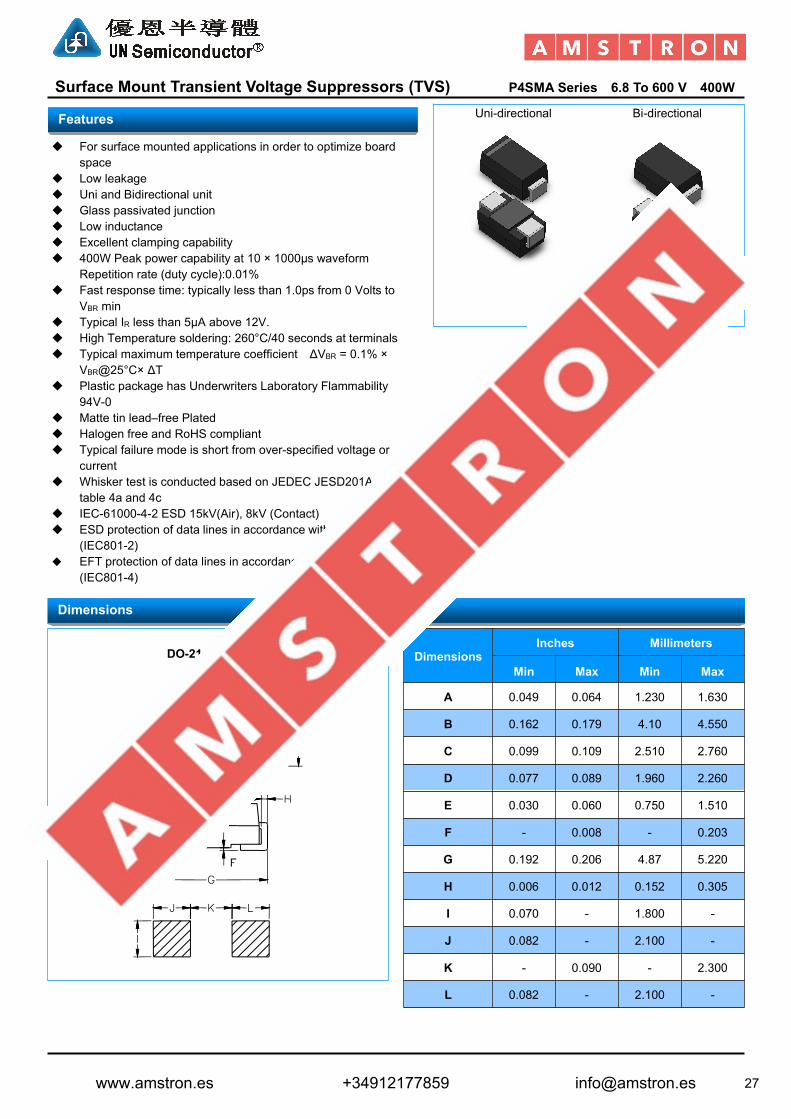
Surface Mount Transient Voltage Suppressors (TVS) P4SMA Series 6.8 To 600 V 400W
Uni-directional Bi-directional
For surface mounted applications in order to optimize boardspace
Low leakage Uni and Bidirectional unit Glass passivated junction Low inductance Excellent clamping capability 400W Peak power capability at 10 × 1000µs waveform
Repetition rate (duty cycle):0.01% Fast response time: typically less than 1.0ps from 0 Volts to
VBR min Typical IR less than 5μA above 12V. High Temperature soldering: 260°C/40 seconds at terminals Typical maximum temperature coefficient ΔVBR = 0.1% ×
VBR@25°C× ΔT Plastic package has Underwriters Laboratory Flammability
94V-0 Matte tin lead–free Plated Halogen free and RoHS compliant Typical failure mode is short from over-specified voltage or
current Whisker test is conducted based on JEDEC JESD201A per its
table 4a and 4c IEC-61000-4-2 ESD 15kV(Air), 8kV (Contact) ESD protection of data lines in accordance with IEC 61000-4-2
(IEC801-2) EFT protection of data lines in accordance with IEC 61000-4-4
(IEC801-4)
DO-214AC (SMA)
DimensionsInches Millimeters
Min Max Min Max
A 0.049 0.064 1.230 1.630
B 0.162 0.179 4.10 4.550
C 0.099 0.109 2.510 2.760
D 0.077 0.089 1.960 2.260
E 0.030 0.060 0.750 1.510
F - 0.008 - 0.203
G 0.192 0.206 4.87 5.220
H 0.006 0.012 0.152 0.305
I 0.070 - 1.800 -
J 0.082 - 2.100 -
K - 0.090 - 2.300
L 0.082 - 2.100 -
Features
Dimensions
DO-214AC (SMA)
Cathode Band
www.amstron.es +34912177859 [email protected]

28
Surface Mount Transient Voltage Suppressors (TVS) P4SMA Series 6.8 To 600 V 400W
Part Number MarkingReverseStand-OffVoltageVRWM(V)
BreakdownVoltage VBR (V)
@IT
TestCurrent
IT(mA)
MaximumClampingVoltageVC
@IPP (V)
MaximumPeakPulseCurrentIPP (A)
MaximumReverseLeakage IR@VRWM(μA)Uni Bi Uni Bi MIN MAX
P4SMA6.8A P4SMA6.8CA 6V8A 6V8C 5.8 6.46 7.14 10 10.5 38.10 1000P4SMA7.5A P4SMA7.5CA 7V5A 7V5C 6.4 7.13 7.88 10 11.3 35.40 500P4SMA8.2A P4SMA8.2CA 8V2A 8V2C 7.0 7.79 8.61 10 12.1 33.06 200P4SMA9.1A P4SMA9.1CA 9V1A 9V1C 7.8 8.65 9.56 1 13.4 29.85 50P4SMA10A P4SMA10CA 10A 10C 8.6 9.50 10.50 1 14.5 27.59 10P4SMA11A P4SMA11CA 11A 11C 9.4 10.45 11.55 1 15.6 25.64 5P4SMA12A P4SMA12CA 12A 12C 10.2 11.40 12.60 1 16.7 23.95 5P4SMA13A P4SMA13CA 13A 13C 11.1 12.35 13.65 1 18.2 21.98 5P4SMA15A P4SMA15CA 15A 15C 12.8 14.25 15.75 1 21.2 18.87 5P4SMA16A P4SMA16CA 16A 16C 13.6 15.20 16.80 1 22.5 17.78 5P4SMA18A P4SMA18CA 18A 18C 15.3 17.10 18.90 1 25.2 15.87 5P4SMA20A P4SMA20CA 20A 20C 17.1 19.00 21.00 1 27.7 14.44 5P4SMA22A P4SMA22CA 22A 22C 18.8 20.90 23.10 1 30.6 13.07 5P4SMA24A P4SMA24CA 24A 24C 20.5 22.80 25.20 1 33.2 12.05 5P4SMA27A P4SMA27CA 27A 27C 23.1 25.65 28.35 1 37.5 10.67 5P4SMA30A P4SMA30CA 30A 30C 25.6 28.50 31.50 1 41.4 9.66 5P4SMA33A P4SMA33CA 33A 33C 28.2 31.35 34.65 1 45.7 8.75 5P4SMA36A P4SMA36CA 36A 36C 30.8 34.20 37.80 1 49.9 8.02 5P4SMA39A P4SMA39CA 39A 39C 33.3 37.05 40.95 1 53.9 7.42 5P4SMA43A P4SMA43CA 43A 43C 36.8 40.85 45.15 1 59.3 6.75 5P4SMA47A P4SMA47CA 47A 47C 40.2 44.65 49.35 1 64.8 6.17 5P4SMA51A P4SMA51CA 51A 51C 43.6 48.45 53.55 1 70.1 5.71 5P4SMA56A P4SMA56CA 56A 56C 47.8 53.20 58.80 1 77.0 5.19 5P4SMA62A P4SMA62CA 62A 62C 53.0 58.90 65.10 1 85.0 4.71 5P4SMA68A P4SMA68CA 68A 68C 58.1 64.60 71.40 1 92.0 4.35 5P4SMA75A P4SMA75CA 75A 75C 64.1 71.25 78.75 1 103.0 3.88 5P4SMA82A P4SMA82CA 82A 82C 70.1 77.90 86.10 1 113.0 3.54 5P4SMA91A P4SMA91CA 91A 91C 77.8 86.45 95.55 1 125.0 3.20 5P4SMA100A P4SMA100CA 100A 100C 85.5 95.00 105.00 1 137.0 2.92 5P4SMA110A P4SMA110CA 110A 110C 94.0 104.50 115.50 1 152.0 2.63 5P4SMA120A P4SMA120CA 120A 120C 102.0 114.00 126.00 1 165.0 2.42 5P4SMA130A P4SMA130CA 130A 130C 111.0 123.50 136.50 1 179.0 2.23 5P4SMA150A P4SMA150CA 150A 150C 128.0 142.50 157.50 1 207.0 1.93 5P4SMA160A P4SMA160CA 160A 160C 136.0 152.00 168.00 1 219.0 1.83 5P4SMA170A P4SMA170CA 170A 170C 145.0 161.50 178.50 1 234.0 1.71 5P4SMA180A P4SMA180CA 180A 180C 154.0 171.00 189.00 1 246.0 1.63 5P4SMA200A P4SMA200CA 200A 200C 171.0 190.00 210.00 1 274.0 1.46 5P4SMA220A P4SMA220CA 220A 220C 185.0 209.00 231.00 1 328.0 1.22 5P4SMA250A P4SMA250CA 250A 250C 214.0 237.50 262.50 1 344.0 1.16 5P4SMA300A P4SMA300CA 300A 300C 256.0 285.00 315.00 1 414.0 0.97 5P4SMA350A P4SMA350CA 350A 350C 299.3 332.50 367.50 1 482.0 0.83 5P4SMA380A P4SMA380CA 380A 380C 324.9 361.00 399.00 1 524.4 0.76 5P4SMA400A P4SMA400CA 400A 400C 342.0 380.00 420.00 1 552.0 0.72 5P4SMA440A P4SMA440CA 440A 440C 376.2 418.00 462.00 1 607.2 0.66 5P4SMA500A P4SMA500CA 500A 500C 427.5 475.00 525.00 1 690.0 0.58 5P4SMA520A P4SMA520CA 520A 520C 444.6 494.00 546.00 1 717.6 0.56 5P4SMA550A P4SMA550CA 550A 550C 470.3 522.50 577.50 1 759.0 0.53 5P4SMA600A P4SMA600CA 600A 600C 513.0 570.00 630.00 1 828.0 0.48 5
Note:1. Suffix 'A ' denotes 5% tolerance device. Without 'A' denotes 10% tolerance device2. Add suffix 'C 'or ' CA ' after part number to specify Bi-directional devices3. For Bi-Directional devices having VR of 10 volts and under, the IR limit is double
Electrical Characteristics (TA=25℃ unless otherwise noted)
www.amstron.es +34912177859 [email protected]

29
Surface Mount Transient Voltage Suppressors (TVS) P6SMBSeries 6.8 To 600 V 600W
Uni-directional Bi-directional
For surface mounted applications in order to optimize boardspace
Low leakage Uni and Bidirectional unit Glass passivated junction Low inductance Excellent clamping capability 600W Peak power capability at 10 × 1000µs waveform
Repetition rate (duty cycle):0.01% Fast response time: typically less than 1.0ps from 0 Volts to
VBR min Typical IR less than 5μA above 12V. High Temperature soldering: 260°C/40 seconds at terminals Typical maximum temperature coefficient ΔVBR = 0.1% ×
VBR@25°C× ΔT Plastic package has Underwriters Laboratory Flammability
94V-0 Matte tin lead–free Plated Halogen free and RoHS compliant Typical failure mode is short from over-specified voltage or
current Whisker test is conducted based on JEDEC JESD201A per its
table 4a and 4c IEC-61000-4-2 ESD 15kV(Air), 8kV (Contact) ESD protection of data lines in accordance with IEC 61000-4-2
(IEC801-2) EFT protection of data lines in accordance with IEC 61000-4-4
(IEC801-4)
DO-214AA (SMB)
DimensionsInches Millimeters
Min Max Min Max
A 0.077 0.087 1.960 2.200
B 0.171 0.191 4.350 4.850
C 0.130 0.155 3.300 3.940
D 0.084 0.096 2.130 2.440
E 0.030 0.060 0.750 1.520
F - 0.008 - 0.203
G 0.201 0.216 5.100 5.500
H 0.006 0.012 0.152 0.305
I 0.089 - 2.260 -
J 0.085 - 2.160 -
K - 0.107 - 2.740
L 0.085 - 2.160 -
Features
Dimensions
DO-214AA (SMB)
Cathode Band
www.amstron.es +34912177859 [email protected]

30
Surface Mount Transient Voltage Suppressors (TVS) P6SMBSeries 6.8 To 600 V 600W
Part Number MarkingReverseStand-OffVoltageVRWM(V)
BreakdownVoltage VBR (V)
@IT
TestCurrent
IT(mA)
MaximumClampingVoltageVC
@IPP (V)
MaximumPeakPulseCurrentIPP (A)
MaximumReverseLeakage IR@VRWM(μA)Uni Bi Uni Bi MIN MAX
P6SMB6.8A P6SMB6.8CA 6V8A 6V8C 5.8 6.46 7.14 10 10.5 57.14 1000P6SMB7.5A P6SMB7.5CA 7V5A 7V5C 6.4 7.13 7.88 10 11.3 53.10 500P6SMB8.2A P6SMB8.2CA 8V2A 8V2C 7.0 7.79 8.61 10 12.1 49.59 200P6SMB9.1A P6SMB9.1CA 9V1A 9V1C 7.8 8.65 9.56 1 13.4 44.78 50P6SMB10A P6SMB10CA 10A 10C 8.6 9.50 10.50 1 14.5 41.38 10P6SMB11A P6SMB11CA 11A 11C 9.4 10.45 11.55 1 15.6 38.46 5P6SMB12A P6SMB12CA 12A 12C 10.2 11.40 12.60 1 16.7 35.93 5P6SMB13A P6SMB13CA 13A 13C 11.1 12.35 13.65 1 18.2 32.97 5P6SMB15A P6SMB15CA 15A 15C 12.8 14.25 15.75 1 21.2 28.30 5P6SMB16A P6SMB16CA 16A 16C 13.6 15.20 16.80 1 22.5 26.67 5P6SMB18A P6SMB18CA 18A 18C 15.3 17.10 18.90 1 25.2 23.81 5P6SMB20A P6SMB20CA 20A 20C 17.1 19.00 21.00 1 27.7 21.66 5P6SMB22A P6SMB22CA 22A 22C 18.8 20.90 23.10 1 30.6 19.61 5P6SMB24A P6SMB24CA 24A 24C 20.5 22.80 25.20 1 33.2 18.07 5P6SMB27A P6SMB27CA 27A 27C 23.1 25.65 28.35 1 37.5 16.00 5P6SMB30A P6SMB30CA 30A 30C 25.6 28.50 31.50 1 41.4 14.49 5P6SMB33A P6SMB33CA 33A 33C 28.2 31.35 34.65 1 45.7 13.13 5P6SMB36A P6SMB36CA 36A 36C 30.8 34.20 37.80 1 49.9 12.02 5P6SMB39A P6SMB39CA 39A 39C 33.3 37.05 40.95 1 53.9 11.13 5P6SMB43A P6SMB43CA 43A 43C 36.8 40.85 45.15 1 59.3 1012 5P6SMB47A P6SMB47CA 47A 47C 40.2 44.65 49.35 1 64.8 9.26 5P6SMB51A P6SMB51CA 51A 51C 43.6 48.45 53.55 1 70.1 8.56 5P6SMB56A P6SMB56CA 56A 56C 47.8 53.20 58.80 1 77.0 7.79 5P6SMB62A P6SMB62CA 62A 62C 53.0 58.90 65.10 1 85.0 7.06 5P6SMB68A P6SMB68CA 68A 68C 58.1 64.60 71.40 1 92.0 6.52 5P6SMB75A P6SMB75CA 75A 75C 64.1 71.25 78.75 1 103.0 5.83 5P6SMB82A P6SMB82CA 82A 82C 70.1 77.90 86.10 1 113.0 5.31 5P6SMB91A P6SMB91CA 91A 91C 77.8 86.45 95.55 1 125.0 4.80 5P6SMB100A P6SMB100CA 100A 100C 85.5 95.00 105.00 1 137.0 4.38 5P6SMB110A P6SMB110CA 110A 110C 94.0 104.50 115.50 1 152.0 3.95 5P6SMB120A P6SMB120CA 120A 120C 102.0 114.00 126.00 1 165.0 3.64 5P6SMB130A P6SMB130CA 130A 130C 111.0 123.50 136.50 1 179.0 3.35 5P6SMB150A P6SMB150CA 150A 150C 128.0 142.50 157.50 1 207.0 2.90 5P6SMB160A P6SMB160CA 160A 160C 136.0 152.00 168.00 1 219.0 2.74 5P6SMB170A P6SMB170CA 170A 170C 145.0 161.50 178.50 1 234.0 2.56 5P6SMB180A P6SMB180CA 180A 180C 154.0 171.00 189.00 1 246.0 2.44 5P6SMB200A P6SMB200CA 200A 200C 171.0 190.00 210.00 1 274.0 2.19 5P6SMB220A P6SMB220CA 220A 220C 185.0 209.00 231.00 1 328.0 1.83 5P6SMB250A P6SMB250CA 250A 250C 214.0 237.50 262.50 1 344.0 1.74 5P6SMB300A P6SMB300CA 300A 300C 256.0 285.00 315.00 1 414.0 1.45 5P6SMB350A P6SMB350CA 350A 350C 299.3 332.50 367.50 1 482.0 1.24 5P6SMB380A P6SMB380CA 380A 380C 324.9 361.00 399.00 1 524.4 1.14 5P6SMB400A P6SMB400CA 400A 400C 342.0 380.00 420.00 1 552.0 1.09 5P6SMB440A P6SMB440CA 440A 440C 376.2 418.00 462.00 1 607.2 0.99 5P6SMB500A P6SMB500CA 500A 500C 427.5 475.00 525.00 1 690.0 0.87 5P6SMB520A P6SMB520CA 520A 520C 444.6 494.00 546.00 1 717.6 0.84 5P6SMB550A P6SMB550CA 550A 550C 470.3 522.50 577.50 1 759.0 0.79 5P6SMB600A P6SMB600CA 600A 600C 513.0 570.00 630.00 1 828.0 0.72 5
Note:1. Suffix 'A ' denotes 5% tolerance device. Without 'A' denotes 10% tolerance device2. Add suffix 'C 'or ' CA ' after part number to specify Bi-directional devices3. For Bi-Directional devices having VR of 10 volts and under, the IR limit is double
Electrical Characteristics (TA=25℃ unless otherwise noted)
www.amstron.es +34912177859 [email protected]

31
Surface Mount Transient Voltage Suppressors (TVS) 1.5SMC Series 6.8 To 600 V 1500W
Uni-directional Bi-directional
For surface mounted applications in order to optimize boardspace
Low leakage Uni and Bidirectional unit Glass passivated junction Low inductance Excellent clamping capability 1500W Peak power capability at 10 × 1000µs waveform
Repetition rate (duty cycle):0.01% Fast response time: typically less than 1.0ps from 0 Volts to
VBR min Typical IR less than 5μA above 12V. High Temperature soldering: 260°C/40 seconds at terminals Typical maximum temperature coefficient ΔVBR = 0.1% ×
VBR@25°C× ΔT Plastic package has Underwriters Laboratory Flammability
94V-0 Matte tin lead–free Plated Halogen free and RoHS compliant Typical failure mode is short from over-specified voltage or
current Whisker test is conducted based on JEDEC JESD201A per its
table 4a and 4c IEC-61000-4-2 ESD 15kV(Air), 8kV (Contact) ESD protection of data lines in accordance with IEC 61000-4-2
(IEC801-2) EFT protection of data lines in accordance with IEC 61000-4-4
(IEC801-4)
DO-214AB (SMC)
DimensionsInches Millimeters
Min Max Min Max
A 0.114 0.126 2.860 3.160
B 0.260 0.280 6.520 7.020
C 0.220 0.245 5.520 6.150
D 0.079 0.103 1.980 2.590
E 0.030 0.060 0.750 1.510
F - 0.008 - 0.203
G 0.305 0.320 7.640 8.020
H 0.006 0.012 0.152 0.305
I 0.129 - 3.300 -
J 0.094 - 2.400 -
K - 0.165 - 4.200
L 0.094 - 2.400 -
Features
Dimensions
DO-214AB (SMC)
Cathode Band
www.amstron.es +34912177859 [email protected]

32
Surface Mount Transient Voltage Suppressors (TVS) 1.5SMC Series 6.8 To 600 V 1500W
Part Number MarkingReverseStand-OffVoltageVRWM(V)
BreakdownVoltage VBR (V)
@IT
TestCurrent
IT(mA)
MaximumClampingVoltageVC
@IPP (V)
MaximumPeakPulseCurrentIPP (A)
MaximumReverseLeakage IR@VRWM(μA)Uni Bi Uni Bi MIN MAX
1.5SMC6.8A 1.5SMC6.8CA 6V8A 6V8C 5.8 6.46 7.14 10 10.5 142.86 10001.5SMC7.5A 1.5SMC7.5CA 7V5A 7V5C 6.4 7.13 7.88 10 11.3 132.74 5001.5SMC8.2A 1.5SMC8.2CA 8V2A 8V2C 7.0 7.79 8.61 10 12.1 123.97 2001.5SMC9.1A 1.5SMC9.1CA 9V1A 9V1C 7.8 8.65 9.56 1 13.4 111.94 501.5SMC10A 1.5SMC10CA 10A 10C 8.6 9.50 10.50 1 14.5 103.45 101.5SMC11A 1.5SMC11CA 11A 11C 9.4 10.45 11.55 1 15.6 96.15 51.5SMC12A 1.5SMC12CA 12A 12C 10.2 11.40 12.60 1 16.7 89.82 51.5SMC13A 1.5SMC13CA 13A 13C 11.1 12.35 13.65 1 18.2 82.42 51.5SMC15A 1.5SMC15CA 15A 15C 12.8 14.25 15.75 1 21.2 70.75 51.5SMC16A 1.5SMC16CA 16A 16C 13.6 15.20 16.80 1 22.5 66.67 51.5SMC18A 1.5SMC18CA 18A 18C 15.3 17.10 18.90 1 25.2 59.52 51.5SMC20A 1.5SMC20CA 20A 20C 17.1 19.00 21.00 1 27.7 54.15 51.5SMC22A 1.5SMC22CA 22A 22C 18.8 20.90 23.10 1 30.6 49.02 51.5SMC24A 1.5SMC24CA 24A 24C 20.5 22.80 25.20 1 33.2 45.18 51.5SMC27A 1.5SMC27CA 27A 27C 23.1 25.65 28.35 1 37.5 40.00 51.5SMC30A 1.5SMC30CA 30A 30C 25.6 28.50 31.50 1 41.4 36.23 51.5SMC33A 1.5SMC33CA 33A 33C 28.2 31.35 34.65 1 45.7 32.82 51.5SMC36A 1.5SMC36CA 36A 36C 30.8 34.20 37.80 1 49.9 30.06 51.5SMC39A 1.5SMC39CA 39A 39C 33.3 37.05 40.95 1 53.9 27.83 51.5SMC43A 1.5SMC43CA 43A 43C 36.8 40.85 45.15 1 59.3 25.30 51.5SMC47A 1.5SMC47CA 47A 47C 40.2 44.65 49.35 1 64.8 23.15 51.5SMC51A 1.5SMC51CA 51A 51C 43.6 48.45 53.55 1 70.1 21.40 51.5SMC56A 1.5SMC56CA 56A 56C 47.8 53.20 58.80 1 77.0 19.48 51.5SMC62A 1.5SMC62CA 62A 62C 53.0 58.90 65.10 1 85.0 17.65 51.5SMC68A 1.5SMC68CA 68A 68C 58.1 64.60 71.40 1 92.0 16.30 51.5SMC75A 1.5SMC75CA 75A 75C 64.1 71.25 78.75 1 103.0 14.56 51.5SMC82A 1.5SMC82CA 82A 82C 70.1 77.90 86.10 1 113.0 13.27 51.5SMC91A 1.5SMC91CA 91A 91C 77.8 86.45 95.55 1 125.0 12.00 51.5SMC100A 1.5SMC100CA 100A 100C 85.5 95.00 105.00 1 137.0 10.95 51.5SMC110A 1.5SMC110CA 110A 110C 94.0 104.50 115.50 1 152.0 9.87 51.5SMC120A 1.5SMC120CA 120A 120C 102.0 114.00 126.00 1 165.0 9.09 51.5SMC130A 1.5SMC130CA 130A 130C 111.0 123.50 136.50 1 179.0 8.38 51.5SMC150A 1.5SMC150CA 150A 150C 128.0 142.50 157.50 1 207.0 7.25 51.5SMC160A 1.5SMC160CA 160A 160C 136.0 152.00 168.00 1 219.0 6.85 51.5SMC170A 1.5SMC170CA 170A 170C 145.0 161.50 178.50 1 234.0 6.41 51.5SMC180A 1.5SMC180CA 180A 180C 154.0 171.00 189.00 1 246.0 6.10 51.5SMC200A 1.5SMC200CA 200A 200C 171.0 190.00 210.00 1 274.0 5.47 51.5SMC220A 1.5SMC220CA 220A 220C 185.0 209.00 231.00 1 328.0 4.57 51.5SMC250A 1.5SMC250CA 250A 250C 214.0 237.50 262.50 1 344.0 4.36 51.5SMC300A 1.5SMC300CA 300A 300C 256.0 285.00 315.00 1 414.0 3.62 51.5SMC350A 1.5SMC350CA 350A 350C 299.3 332.50 367.50 1 482.0 3.11 51.5SMC380A 1.5SMC380CA 380A 380C 324.9 361.00 399.00 1 524.4 2.86 51.5SMC400A 1.5SMC400CA 400A 400C 342.0 380.00 420.00 1 552.0 2.72 51.5SMC440A 1.5SMC440CA 440A 440C 376.2 418.00 462.00 1 607.2 2.47 51.5SMC500A 1.5SMC500CA 500A 500C 427.5 475.00 525.00 1 690.0 2.17 51.5SMC520A 1.5SMC520CA 520A 520C 444.6 494.00 546.00 1 717.6 2.09 51.5SMC550A 1.5SMC550CA 550A 550C 470.3 522.50 577.50 1 759.0 1.98 51.5SMC600A 1.5SMC600CA 600A 600C 513.0 570.00 630.00 1 828.0 1.81 5Note:1. Suffix 'A ' denotes 5% tolerance device. Without 'A' denotes 10% tolerance device2. Add suffix 'C 'or ' CA ' after part number to specify Bi-directional devices3. For Bi-Directional devices having VR of 10 volts and under, the IR limit is double
Electrical Characteristics (TA=25℃ unless otherwise noted)
www.amstron.es +34912177859 [email protected]

33
Surface Mount Transient Voltage Suppressors (TVS) 5.0SMDJ Series 11 To 440 V 5000W
Uni-directional Bi-directional
For surface mounted applications in order to optimize boardspace
Low leakage Uni and Bidirectional unit Glass passivated junction Low inductance Excellent clamping capability 5000W Peak power capability at 10 × 1000µs waveform
Repetition rate (duty cycle):0.01% Fast response time: typically less than 1.0ps from 0 Volts to
VBR min Typical IR less than 5μA above 25V. High Temperature soldering: 260°C/40 seconds at terminals Typical maximum temperature coefficient ΔVBR = 0.1% ×
VBR@25°C× ΔT Plastic package has Underwriters Laboratory Flammability
94V-0 Matte tin lead–free Plated Halogen free and RoHS compliant Typical failure mode is short from over-specified voltage or
current Whisker test is conducted based on JEDEC JESD201A per its
table 4a and 4c IEC-61000-4-2 ESD 15kV(Air), 8kV (Contact) ESD protection of data lines in accordance with IEC 61000-4-2
(IEC801-2) EFT protection of data lines in accordance with IEC 61000-4-4
(IEC801-4)
DO-214AB (SMC)
DimensionsInches Millimeters
Min Max Min Max
A 0.114 0.126 2.860 3.160
B 0.260 0.280 6.520 7.020
C 0.220 0.245 5.520 6.150
D 0.079 0.103 1.980 2.590
E 0.030 0.060 0.750 1.510
F - 0.008 - 0.203
G 0.305 0.320 7.640 8.020
H 0.006 0.012 0.152 0.305
I 0.129 - 3.300 -
J 0.094 - 2.400 -
K - 0.165 - 4.200
L 0.094 - 2.400 -
Features
Dimensions
DO-214AB (SMC)
Cathode Band
www.amstron.es +34912177859 [email protected]
34
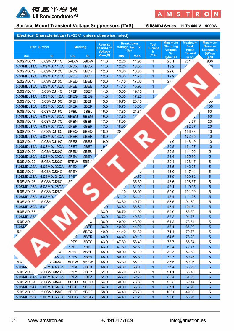
Surface Mount Transient Voltage Suppressors (TVS) 5.0SMDJ Series 11 To 440 V 5000W
Part Number MarkingReverseStand-OffVoltageVRWM(V)
BreakdownVoltage VBR (V)
@IT
TestCurrent
IT(mA)
MaximumClampingVoltageVC
@IPP (V)
MaximumPeakPulseCurrentIPP (A)
MaximumReverseLeakage IR@VRWM(μA)Uni Bi Uni Bi MIN MAX
5.0SMDJ11 5.0SMDJ11C 5PDW 5BDW 11.0 12.20 14.90 1 20.1 251.24 8005.0SMDJ11A 5.0SMDJ11CA 5PDX 5BDX 11.0 12.20 13.50 1 18.2 277.47 8005.0SMDJ12 5.0SMDJ12C 5PDY 5BDY 12.0 13.30 16.30 1 22.0 229.55 8005.0SMDJ12A 5.0SMDJ12CA 5PDZ 5BDZ 12.0 13.30 14.70 1 19.9 253.77 8005.0SMDJ13 5.0SMDJ13C 5PED 5BED 13.0 14.40 17.60 1 23.8 212.18 5005.0SMDJ13A 5.0SMDJ13CA 5PEE 5BEE 13.0 14.40 15.90 1 21.5 234.88 5005.0SMDJ14 5.0SMDJ14C 5PEF 5BEF 14.0 15.60 19.10 1 25.8 195.74 2005.0SMDJ14A 5.0SMDJ14CA 5PEG 5BEG 14.0 15.60 17.20 1 23.2 217.67 2005.0SMDJ15 5.0SMDJ15C 5PEH 5BEH 15.0 16.70 20.40 1 26.9 187.73 1005.0SMDJ15A 5.0SMDJ15CA 5PEK 5BEK 15.0 16.70 18.50 1 24.4 206.97 1005.0SMDJ16 5.0SMDJ16C 5PEL 5BEL 16.0 17.80 21.80 1 28.8 175.35 505.0SMDJ16A 5.0SMDJ16CA 5PEM 5BEM 16.0 17.80 19.70 1 26.0 194.23 505.0SMDJ17 5.0SMDJ17C 5PEN 5BEN 17.0 18.90 23.10 1 30.5 165.57 205.0SMDJ17A 5.0SMDJ17CA 5PEP 5BEP 17.0 18.90 20.90 1 27.6 182.97 205.0SMDJ18 5.0SMDJ18C 5PEQ 5BEQ 18.0 20.00 24.40 1 32.2 156.83 105.0SMDJ18A 5.0SMDJ18CA 5PER 5BER 18.0 20.00 22.10 1 29.2 172.95 105.0SMDJ19 5.0SMDJ19C 5PES 5BES 19.0 21.13 25.76 1 34.0 148.49 105.0SMDJ19A 5.0SMDJ19CA 5PET 5BET 19.0 21.10 23.30 1 30.8 164.07 105.0SMDJ20 5.0SMDJ20C 5PEU 5BEU 20.0 22.20 27.10 1 35.8 141.06 55.0SMDJ20A 5.0SMDJ20CA 5PEV 5BEV 20.0 22.20 24.50 1 32.4 155.86 55.0SMDJ22 5.0SMDJ22C 5PEW 5BEW 22.0 24.40 29.80 1 39.4 128.17 55.0SMDJ22A 5.0SMDJ22CA 5PEX 5BEX 22.0 24.40 26.90 1 35.5 142.25 55.0SMDJ24 5.0SMDJ24C 5PEY 5BEY 24.0 26.70 32.60 1 43.0 117.44 55.0SMDJ24A 5.0SMDJ24CA 5PEZ 5BEZ 24.0 26.70 29.50 1 38.9 129.82 55.0SMDJ26 5.0SMDJ26C 5PFD 5BFD 26.0 28.90 35.30 1 46.6 108.37 55.0SMDJ26A 5.0SMDJ26CA 5PFE 5BFE 26.0 28.90 31.90 1 42.1 119.95 55.0SMDJ28 5.0SMDJ28C 5PFF 5BFF 28.0 31.10 38.00 1 50.0 101.00 55.0SMDJ28A 5.0SMDJ28CA 5PFG 5BFG 28.0 31.10 34.40 1 45.4 111.23 55.0SMDJ30 5.0SMDJ30C 5PFH 5BFH 30.0 33.30 40.70 1 53.5 94.39 55.0SMDJ30A 5.0SMDJ30CA 5PFK 5BFK 30.0 33.30 36.80 1 48.4 104.34 55.0SMDJ33 5.0SMDJ33C 5PFL 5BFL 33.0 36.70 44.90 1 59.0 85.59 55.0SMDJ33A 5.0SMDJ33CA 5PFM 5BFM 33.0 36.70 40.60 1 53.3 94.75 55.0SMDJ36 5.0SMDJ36C 5PFN 5BFN 36.0 40.00 48.90 1 64.3 78.54 55.0SMDJ36A 5.0SMDJ36CA 5PFP 5BFP 36.0 40.00 44.20 1 58.1 86.92 55.0SMDJ40 5.0SMDJ40C 5PFQ 5BFQ 40.0 44.40 54.30 1 71.4 70.73 55.0SMDJ40A 5.0SMDJ40CA 5PFR 5BFR 40.0 44.40 49.10 1 64.5 78.29 55.0SMDJ43 5.0SMDJ43C 5PFS 5BFS 43.0 47.80 58.40 1 76.7 65.84 55.0SMDJ43A 5.0SMDJ43CA 5PFT 5BFT 43.0 47.80 52.80 1 69.4 72.77 55.0SMDJ45 5.0SMDJ45C 5PFU 5BFU 45.0 50.00 61.10 1 80.3 62.89 55.0SMDJ45A 5.0SMDJ45CA 5PFV 5BFV 45.0 50.00 55.30 1 72.7 69.46 55.0SMDJ48 5.0SMDJ48C 5PFW 5BFW 48.0 53.30 65.10 1 85.5 59.06 55.0SMDJ48A 5.0SMDJ48CA 5PFX 5BFX 48.0 53.30 58.90 1 77.4 65.25 55.0SMDJ51 5.0SMDJ51C 5PFY 5BFY 51.0 56.70 69.30 1 91.1 55.43 55.0SMDJ51A 5.0SMDJ51CA 5PFZ 5BFZ 51.0 56.70 62.70 1 82.4 61.29 55.0SMDJ54 5.0SMDJ54C 5PGD 5BGD 54.0 60.00 73.30 1 96.3 52.44 55.0SMDJ54A 5.0SMDJ54CA 5PGE 5BGE 54.0 60.00 66.30 1 87.1 57.98 55.0SMDJ58 5.0SMDJ58C 5PGF 5BGF 58.0 64.40 78.70 1 103.0 49.03 55.0SMDJ58A 5.0SMDJ58CA 5PGG 5BGG 58.0 64.40 71.20 1 93.6 53.95 5
Electrical Characteristics (TA=25℃ unless otherwise noted)
www.amstron.es +34912177859 [email protected]
35
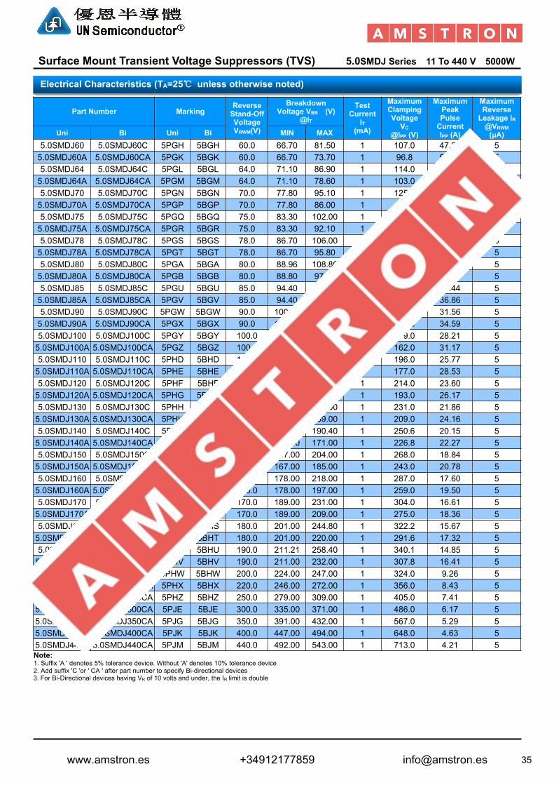
Surface Mount Transient Voltage Suppressors (TVS) 5.0SMDJ Series 11 To 440 V 5000W
Part Number MarkingReverseStand-OffVoltageVRWM(V)
BreakdownVoltage VBR (V)
@IT
TestCurrent
IT(mA)
MaximumClampingVoltageVC
@IPP (V)
MaximumPeakPulseCurrentIPP (A)
MaximumReverseLeakage IR@VRWM(μA)Uni Bi Uni Bi MIN MAX
5.0SMDJ60 5.0SMDJ60C 5PGH 5BGH 60.0 66.70 81.50 1 107.0 47.20 55.0SMDJ60A 5.0SMDJ60CA 5PGK 5BGK 60.0 66.70 73.70 1 96.8 52.17 55.0SMDJ64 5.0SMDJ64C 5PGL 5BGL 64.0 71.10 86.90 1 114.0 44.30 55.0SMDJ64A 5.0SMDJ64CA 5PGM 5BGM 64.0 71.10 78.60 1 103.0 49.03 55.0SMDJ70 5.0SMDJ70C 5PGN 5BGN 70.0 77.80 95.10 1 125.0 40.40 55.0SMDJ70A 5.0SMDJ70CA 5PGP 5BGP 70.0 77.80 86.00 1 113.0 44.69 55.0SMDJ75 5.0SMDJ75C 5PGQ 5BGQ 75.0 83.30 102.00 1 134.0 37.69 55.0SMDJ75A 5.0SMDJ75CA 5PGR 5BGR 75.0 83.30 92.10 1 121.0 41.74 55.0SMDJ78 5.0SMDJ78C 5PGS 5BGS 78.0 86.70 106.00 1 139.0 36.33 55.0SMDJ78A 5.0SMDJ78CA 5PGT 5BGT 78.0 86.70 95.80 1 126.0 40.08 55.0SMDJ80 5.0SMDJ80C 5PGA 5BGA 80.0 88.96 108.80 1 143.2 35.27 55.0SMDJ80A 5.0SMDJ80CA 5PGB 5BGB 80.0 88.80 97.60 1 129.6 38.97 55.0SMDJ85 5.0SMDJ85C 5PGU 5BGU 85.0 94.40 115.00 1 151.0 33.44 55.0SMDJ85A 5.0SMDJ85CA 5PGV 5BGV 85.0 94.40 104.00 1 137.0 36.86 55.0SMDJ90 5.0SMDJ90C 5PGW 5BGW 90.0 100.00 122.00 1 160.0 31.56 55.0SMDJ90A 5.0SMDJ90CA 5PGX 5BGX 90.0 100.00 111.00 1 146.0 34.59 55.0SMDJ100 5.0SMDJ100C 5PGY 5BGY 100.0 111.00 136.00 1 179.0 28.21 55.0SMDJ100A 5.0SMDJ100CA 5PGZ 5BGZ 100.0 111.00 123.00 1 162.0 31.17 55.0SMDJ110 5.0SMDJ110C 5PHD 5BHD 110.0 122.00 149.00 1 196.0 25.77 55.0SMDJ110A 5.0SMDJ110CA 5PHE 5BHE 110.0 122.00 135.00 1 177.0 28.53 55.0SMDJ120 5.0SMDJ120C 5PHF 5BHF 120.0 133.00 163.00 1 214.0 23.60 55.0SMDJ120A 5.0SMDJ120CA 5PHG 5BHG 120.0 133.00 147.00 1 193.0 26.17 55.0SMDJ130 5.0SMDJ130C 5PHH 5BHH 130.0 144.00 176.00 1 231.0 21.86 55.0SMDJ130A 5.0SMDJ130CA 5PHK 5BHK 130.0 144.00 159.00 1 209.0 24.16 55.0SMDJ140 5.0SMDJ140C 5PHA 5BHA 140.0 155.68 190.40 1 250.6 20.15 55.0SMDJ140A 5.0SMDJ140CA 5PHB 5BHB 140.0 155.00 171.00 1 226.8 22.27 55.0SMDJ150 5.0SMDJ150C 5PHL 5BHL 150.0 167.00 204.00 1 268.0 18.84 55.0SMDJ150A 5.0SMDJ150CA 5PHM 5BHM 150.0 167.00 185.00 1 243.0 20.78 55.0SMDJ160 5.0SMDJ160C 5PHN 5BHN 160.0 178.00 218.00 1 287.0 17.60 55.0SMDJ160A 5.0SMDJ160CA 5PHP 5BHP 160.0 178.00 197.00 1 259.0 19.50 55.0SMDJ170 5.0SMDJ170C 5PHQ 5BHQ 170.0 189.00 231.00 1 304.0 16.61 55.0SMDJ170A 5.0SMDJ170CA 5PHR 5BHR 170.0 189.00 209.00 1 275.0 18.36 55.0SMDJ180 5.0SMDJ180C 5PHS 5BHS 180.0 201.00 244.80 1 322.2 15.67 55.0SMDJ180A 5.0SMDJ180CA 5PHT 5BHT 180.0 201.00 220.00 1 291.6 17.32 55.0SMDJ190 5.0SMDJ190C 5PHU 5BHU 190.0 211.21 258.40 1 340.1 14.85 55.0SMDJ190A 5.0SMDJ190CA 5PHV 5BHV 190.0 211.00 232.00 1 307.8 16.41 55.0SMDJ200A 5.0SMDJ200CA 5PHW 5BHW 200.0 224.00 247.00 1 324.0 9.26 55.0SMDJ220A 5.0SMDJ220CA 5PHX 5BHX 220.0 246.00 272.00 1 356.0 8.43 55.0SMDJ250A 5.0SMDJ250CA 5PHZ 5BHZ 250.0 279.00 309.00 1 405.0 7.41 55.0SMDJ300A 5.0SMDJ300CA 5PJE 5BJE 300.0 335.00 371.00 1 486.0 6.17 55.0SMDJ350A 5.0SMDJ350CA 5PJG 5BJG 350.0 391.00 432.00 1 567.0 5.29 55.0SMDJ400A 5.0SMDJ400CA 5PJK 5BJK 400.0 447.00 494.00 1 648.0 4.63 55.0SMDJ440A 5.0SMDJ440CA 5PJM 5BJM 440.0 492.00 543.00 1 713.0 4.21 5Note:1. Suffix 'A ' denotes 5% tolerance device. Without 'A' denotes 10% tolerance device2. Add suffix 'C 'or ' CA ' after part number to specify Bi-directional devices3. For Bi-Directional devices having VR of 10 volts and under, the IR limit is double
Electrical Characteristics (TA=25℃ unless otherwise noted)
www.amstron.es +34912177859 [email protected]
36
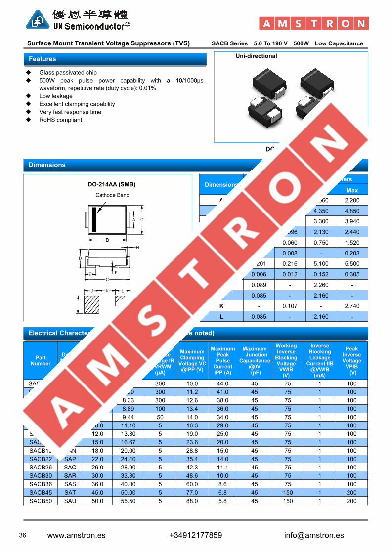
Surface Mount Transient Voltage Suppressors (TVS) SACB Series 5.0 To 190 V 500W Low Capacitance
Uni-directional
Glass passivated chip 500W peak pulse power capability with a 10/1000µs
waveform, repetitive rate (duty cycle): 0.01% Low leakage Excellent clamping capability Very fast response time RoHS compliant
DO-214AA(SMB)
DimensionsInches Millimeters
Min Max Min MaxA 0.077 0.087 1.960 2.200
B 0.171 0.191 4.350 4.850
C 0.130 0.155 3.300 3.940
D 0.084 0.096 2.130 2.440
E 0.030 0.060 0.750 1.520
F - 0.008 - 0.203
G 0.201 0.216 5.100 5.500
H 0.006 0.012 0.152 0.305
I 0.089 - 2.260 -
J 0.085 - 2.160 -
K - 0.107 - 2.740
L 0.085 - 2.160 -
PartNumber
DeviceMarkingCode
ReverseStand-OffVoltageVRWM (V)
BreakdownVoltage VBR@IT=1.0mA
(V)
MaximumReverse
Leakage IR@VRWM(μA)
MaximumClampingVoltage VC@IPP (V)
MaximumPeakPulseCurrentIPP (A)
MaximumJunction
Capacitance@0V(pF)
WorkingInverseBlockingVoltageVWIB(V)
InverseBlockingLeakageCurrent IIB@VWIB(mA)
PeakInverseVoltageVPIB(V)MIN
SACB5.0 SAD 5.0 7.60 300 10.0 44.0 45 75 1 100SACB6.0 SAE 6.0 7.90 300 11.2 41.0 45 75 1 100SACB7.0 SAF 7.0 8.33 300 12.6 38.0 45 75 1 100SACB8.0 SAG 8.0 8.89 100 13.4 36.0 45 75 1 100SACB8.5 SAH 8.5 9.44 50 14.0 34.0 45 75 1 100SACB10 SAK 10.0 11.10 5 16.3 29.0 45 75 1 100SACB12 SAL 12.0 13.30 5 19.0 25.0 45 75 1 100SACB15 SAM 15.0 16.67 5 23.6 20.0 45 75 1 100SACB18 SAN 18.0 20.00 5 28.8 15.0 45 75 1 100SACB22 SAP 22.0 24.40 5 35.4 14.0 45 75 1 100SACB26 SAQ 26.0 28.90 5 42.3 11.1 45 75 1 100SACB30 SAR 30.0 33.30 5 48.6 10.0 45 75 1 100SACB36 SAS 36.0 40.00 5 60.0 8.6 45 75 1 100SACB45 SAT 45.0 50.00 5 77.0 6.8 45 150 1 200SACB50 SAU 50.0 55.50 5 88.0 5.8 45 150 1 200
Electrical Characteristics (TA=25℃ unless otherwise noted)
Dimensions
Features
DO-214AA (SMB)
Cathode Band
www.amstron.es +34912177859 [email protected]

37
Surface Mount Transient Voltage Suppressors (TVS) SM8S Series 10 To 43 V 6600W
Junction passivation optimized design passivated anisotropicrectifier technology
TJ=175°C capability suitable for high reliability and automotiverequirement
Available in uni-directional polarity only Low leakage current Low forward voltage drop High surge capability Meets ISO7637-2 surge specification (varied by test condition) Meets MSL level 1, per J-STD-020, LF maximum peak of
245 °C AEC-Q101 qualified Compliant to RoHS Directive 2002/95/EC and in accordance to
WEEE 2002/96/EC
DO-218AB
Dimensions
Features
www.amstron.es +34912177859 [email protected]

38
Surface Mount Transient Voltage Suppressors (TVS) SM8S Series 10 To 43 V 6600W
Part NumberStand-OffVoltageVMW(V)
BreakdownVoltageVBR (V)
TestCurrent
IT(mA)
MaximumReverseLeakageat VWMID(µA)
MaximumReverseat VWM
TJ=175°CID(µA)
MaximumPeak PulseCurrent
at 10/1000µsWaveform
(A)
MaximumClampingVoltageat IPPMVC (V)MIN. MAX.
SM8S10 10.0 11.1 13.6 5.0 15 250 351 18.8SM8S10A 10.0 11.1 12.3 5.0 15 250 388 17.0SM8S11 11.0 12.2 14.9 5.0 10 150 328 20.1SM8S11A 11.0 12.2 13.5 5.0 10 150 363 18.2SM8S12 12.0 13.3 16.3 5.0 10 150 300 22.0SM8S12A 12.0 13.3 14.7 5.0 10 150 332 19.9SM8S13 13.0 14.4 17.6 5.0 10 150 277 23.8SM8S13A 13.0 14.4 15.9 5.0 10 150 307 21.5SM8S14 14.0 15.6 19.1 5.0 10 150 256 25.8SM8S14A 14.0 15.6 17.2 5.0 10 150 284 23.2SM8S15 15.0 16.7 20.4 5.0 10 150 245 26.9SM8S15A 15.0 16.7 18.5 5.0 10 150 270 24.4SM8S16 16.0 17.8 21.8 5.0 10 150 229 28.8SM8S16A 16.0 17.8 19.7 5.0 10 150 254 26.0SM8S17 17.0 18.9 23.1 5.0 10 150 216 30.5SM8S17A 17.0 18.9 20.9 5.0 10 150 239 27.6SM8S18 18.0 20.0 24.4 5.0 10 150 205 32.2SM8S18A 18.0 20.0 22.1 5.0 10 150 226 29.2SM8S20 20.0 22.2 27.1 5.0 10 150 184 35.8SM8S20A 20.0 22.2 24.5 5.0 10 150 204 32.4SM8S22 22.0 24.4 29.8 5.0 10 150 168 39.4SM8S22A 22.0 24.4 26.9 5.0 10 150 186 35.5SM8S24 24.0 26.7 32.6 5.0 10 150 153 43.0SM8S24A 24.0 26.7 29.5 5.0 10 150 170 38.9SM8S26 26.0 28.9 35.3 5.0 10 150 142 46.6SM8S26A 26.0 28.9 31.9 5.0 10 150 157 42.1SM8S28 28.0 31.1 38.0 5.0 10 150 132 50.1SM8S28A 28.0 31.1 34.4 5.0 10 150 145 45.4SM8S30 30.0 33.3 40.7 5.0 10 150 123 53.5SM8S30A 30.0 33.3 36.8 5.0 10 150 136 48.4SM8S33 33.0 36.7 44.9 5.0 10 150 112 59.0SM8S33A 33.0 36.7 40.6 5.0 10 150 124 53.3SM8S36 36.0 40.0 48.9 5.0 10 150 103 64.3SM8S36A 36.0 40.0 44.2 5.0 10 150 114 58.1SM8S40 40.0 44.4 54.3 5.0 10 150 92.4 71.4SM8S40A 40.0 44.4 49.1 5.0 10 150 102 64.5SM8S43 43.0 47.8 58.4 5.0 10 150 86 76.7SM8S43A 43.0 47.8 52.8 5.0 10 150 95.1 69.4
Note:For all types maximum VF = 1.8V at IF = 100A measured on 8.3 ms single half sine-wave or equivalent square wave, duty cycle = 4 pulses perminute maximum.
Electrical Characteristics (TA=25℃ unless otherwise noted)
www.amstron.es +34912177859 [email protected]

39
Axial Lead Transient Voltage Suppressors (TVS) P4KE Series 6.8 To 600 V 400W
Uni-directional Bi-directional
Glass passivated chip junction in DO-41 Package Low leakage Uni and Bidirectional unit Excellent clamping capability 400W Peak power capability at 10 × 1000µs waveform
Repetition rate (duty cycle):0.01% Fast response time: typically less than 1.0ps from 0 Volts to
VBR min Typical IR less than 5μA above 12V. High Temperature soldering: 260°C/40 seconds at terminals Typical maximum temperature coefficient ΔVBR = 0.1% ×
VBR@25°C× ΔT Plastic package has Underwriters Laboratory Flammability
94V-0 Matte tin lead–free Plated Halogen free and RoHS compliant Typical failure mode is short from over-specified voltage or
current Whisker test is conducted based on JEDEC JESD201A per its
table 4a and 4c IEC-61000-4-2 ESD 15kV(Air), 8kV (Contact) ESD protection of data lines in accordance with IEC 61000-4-2
(IEC801-2) EFT protection of data lines in accordance with IEC 61000-4-4
(IEC801-4)
DO-204AL (DO-41)
DimensionsInches Millimeters
Min Max Min Max
A 1.000 - 25.40 -
B 0.165 0.205 4.19 5.21
C 0.028 0.033 0.71 0.84
D 0.090 0.117 2.29 2.97
Features
Dimensions
DO-204AL (DO-41)
Cathode Band
www.amstron.es +34912177859 [email protected]

40
Axial Lead Transient Voltage Suppressors (TVS) P4KE Series 6.8 To 600 V 400W
Part NumberReverseStand-OffVoltageVRWM(V)
BreakdownVoltage VBR (V)
@ITTest
CurrentIT (mA)
MaximumClampingVoltage
VC@IPP (V)
MaximumPeakPulseCurrentIPP (A)
MaximumReverseLeakage IR@VRWM(μA)Uni Bi MIN MAX
P4KE6.8 P4KE6.8C 5.5 6.12 7.48 10 10.8 37.04 1000P4KE6.8A P4KE6.8CA 5.8 6.46 7.14 10 10.5 38.10 1000P4KE7.5 P4KE7.5C 6.1 6.75 8.25 10 11.7 34.19 500P4KE7.5A P4KE7.5CA 6.4 7.13 7.88 10 11.3 35.40 500P4KE8.2 P4KE8.2C 6.6 7.38 9.02 10 12.5 32.00 200P4KE8.2A P4KE8.2CA 7.0 7.79 8.61 10 12.1 33.06 200P4KE9.1 P4KE9.1C 7.4 8.19 10.01 1 13.8 28.99 50P4KE9.1A P4KE9.1CA 7.8 8.65 9.56 1 13.4 29.85 50P4KE10 P4KE10C 8.1 9.00 11.00 1 15.0 26.67 10P4KE10A P4KE10CA 8.6 9.50 10.50 1 14.5 27.59 10P4KE11 P4KE11C 8.9 9.90 12.10 1 16.2 24.69 5P4KE11A P4KE11CA 9.4 10.45 11.55 1 15.6 25.64 5P4KE12 P4KE12C 9.7 10.80 13.20 1 17.3 23.12 5P4KE12A P4KE12CA 10.2 11.40 12.60 1 16.7 23.95 5P4KE13 P4KE13C 10.5 11.70 14.30 1 19.0 21.05 5P4KE13A P4KE13CA 11.1 12.35 13.65 1 18.2 21.98 5P4KE15 P4KE15C 12.1 13.50 16.50 1 22.0 18.18 5P4KE15A P4KE15CA 12.8 14.25 15.75 1 21.2 18.87 5P4KE16 P4KE16C 12.9 14.40 17.60 1 23.5 17.02 5P4KE16A P4KE16CA 13.6 15.20 16.80 1 22.5 17.78 5P4KE18 P4KE18C 14.5 16.20 19.80 1 26.5 15.09 5P4KE18A P4KE18CA 15.3 17.10 18.90 1 25.2 15.87 5P4KE20 P4KE20C 16.2 18.00 22.00 1 29.1 13.75 5P4KE20A P4KE20CA 17.1 19.00 21.00 1 27.7 14.44 5P4KE22 P4KE22C 17.8 19.80 24.20 1 31.9 12.54 5P4KE22A P4KE22CA 18.8 20.90 23.10 1 30.6 13.07 5P4KE24 P4KE24C 19.4 21.60 26.40 1 34.7 11.53 5P4KE24A P4KE24CA 20.5 22.80 25.20 1 33.2 12.05 5P4KE27 P4KE27C 21.8 24.30 29.70 1 39.1 10.23 5P4KE27A P4KE27CA 23.1 25.65 28.35 1 37.5 10.67 5P4KE30 P4KE30C 24.3 27.00 33.00 1 43.5 9.20 5P4KE30A P4KE30CA 25.6 28.50 31.50 1 41.4 9.66 5P4KE33 P4KE33C 26.8 29.70 36.30 1 47.7 8.39 5P4KE33A P4KE33CA 28.2 31.35 34.65 1 45.7 8.75 5P4KE36 P4KE36C 29.1 32.40 39.60 1 52.0 7.69 5P4KE36A P4KE36CA 30.8 34.20 37.80 1 49.9 8.02 5P4KE39 P4KE39C 31.6 35.10 42.90 1 56.4 7.09 5P4KE39A P4KE39CA 33.3 37.05 40.95 1 53.9 7.42 5P4KE43 P4KE43C 34.8 38.70 47.30 1 61.9 6.46 5P4KE43A P4KE43CA 36.8 40.85 45.15 1 59.3 6.75 5P4KE47 P4KE47C 38.1 42.30 51.70 1 67.8 5.90 5P4KE47A P4KE47CA 40.2 44.65 49.35 1 64.8 6.17 5P4KE51 P4KE51C 41.3 45.90 56.10 1 73.5 5.44 5P4KE51A P4KE51CA 43.6 48.45 53.55 1 70.1 5.71 5P4KE56 P4KE56C 45.4 50.40 61.60 1 80.5 4.97 5P4KE56A P4KE56CA 47.8 53.20 58.80 1 77.0 5.19 5P4KE62 P4KE62C 50.2 55.80 68.20 1 89.0 4.49 5P4KE62A P4KE62CA 53.0 58.90 65.10 1 85.0 4.71 5P4KE68 P4KE68C 55.1 61.20 74.80 1 98.0 4.08 5P4KE68A P4KE68CA 58.1 64.60 71.40 1 92.0 4.35 5P4KE75 P4KE75C 60.7 67.50 82.50 1 108.0 3.70 5P4KE75A P4KE75CA 64.1 71.25 78.75 1 103.0 3.88 5P4KE82 P4KE82C 66.4 73.80 90.20 1 118.0 3.39 5P4KE82A P4KE82CA 70.1 77.90 86.10 1 113.0 3.54 5
Electrical Characteristics (TA=25℃ unless otherwise noted)
www.amstron.es +34912177859 [email protected]

41
Axial Lead Transient Voltage Suppressors (TVS) P4KE Series 6.8 To 600 V 400W
Part NumberReverseStand-OffVoltageVRWM(V)
BreakdownVoltage VBR (V)
@ITTest
CurrentIT (mA)
MaximumClampingVoltage
VC@IPP (V)
MaximumPeakPulseCurrentIPP (A)
MaximumReverseLeakage IR@VRWM(μA)Uni Bi MIN MAX
P4KE91 P4KE91C 73.7 81.90 100.10 1 131.0 3.05 5P4KE91A P4KE91CA 77.8 86.45 95.55 1 125.0 3.20 5P4KE100 P4KE100C 81.0 90.00 110.00 1 144.0 2.78 5P4KE100A P4KE100CA 85.5 95.00 105.00 1 137.0 2.92 5P4KE110 P4KE110C 89.2 99.00 121.00 1 158.0 2.53 5P4KE110A P4KE110CA 94.0 104.50 115.50 1 152.0 2.63 5P4KE120 P4KE120C 97.2 108.00 132.00 1 173.0 2.31 5P4KE120A P4KE120CA 102.0 114.00 126.00 1 165.0 2.42 5P4KE130 P4KE130C 105.0 117.00 143.00 1 187.0 2.14 5P4KE130A P4KE130CA 111.0 123.50 136.50 1 179.0 2.23 5P4KE150 P4KE150C 121.0 135.00 165.00 1 215.0 1.86 5P4KE150A P4KE150CA 128.0 142.50 157.50 1 207.0 1.93 5P4KE160 P4KE160C 130.0 144.00 176.00 1 230.0 1.74 5P4KE160A P4KE160CA 136.0 152.00 168.00 1 219.0 1.83 5P4KE170 P4KE170C 138.0 153.00 187.00 1 244.0 1.64 5P4KE170A P4KE170CA 145.0 161.50 178.50 1 234.0 1.71 5P4KE180 P4KE180C 146.0 162.00 198.00 1 258.0 1.55 5P4KE180A P4KE180CA 154.0 171.00 189.00 1 246.0 1.63 5P4KE200 P4KE200C 162.0 180.00 220.00 1 287.0 1.39 5P4KE200A P4KE200CA 171.0 190.00 210.00 1 274.0 1.46 5P4KE220 P4KE220C 175.0 198.00 242.00 1 344.0 1.16 5P4KE220A P4KE220CA 185.0 209.00 231.00 1 328.0 1.22 5P4KE250 P4KE250C 202.0 225.00 275.00 1 360.0 1.11 5P4KE250A P4KE250CA 214.0 237.50 262.50 1 344.0 1.16 5P4KE300 P4KE300C 243.0 270.00 330.00 1 430.0 0.93 5P4KE300A P4KE300CA 256.0 285.00 315.00 1 414.0 0.97 5P4KE350 P4KE350C 284.0 315.00 385.00 1 504.0 0.79 5P4KE350A P4KE350CA 299.3 332.50 367.50 1 482.0 0.83 5P4KE380 P4KE380C 308.6 342.00 418.00 1 547.2 0.73 5P4KE380A P4KE380CA 324.9 361.00 399.00 1 524.4 0.76 5P4KE400 P4KE400C 324.8 360.00 440.00 1 576.0 0.69 5P4KE400A P4KE400CA 342.0 380.00 420.00 1 552.0 0.72 5P4KE440 P4KE440C 357.3 396.00 484.00 1 633.6 0.63 5P4KE440A P4KE440CA 376.2 418.00 462.00 1 607.2 0.66 5P4KE500 P4KE500C 406.0 450.00 550.00 1 720.0 0.56 5P4KE500A P4KE500CA 427.5 475.00 525.00 1 690.0 0.58 5P4KE520 P4KE520C 422.2 468.00 572.00 1 748.8 0.53 5P4KE520A P4KE520CA 444.6 494.00 546.00 1 717.6 0.56 5P4KE550 P4KE550C 446.6 495.00 605.00 1 792.0 0.51 5P4KE550A P4KE550CA 470.3 522.50 577.50 1 759.0 0.53 5P4KE600 P4KE600C 487.2 540.00 660.00 1 864.0 0.46 5P4KE600A P4KE600CA 513.0 570.00 630.00 1 828.0 0.48 5
Note:1. Suffix 'A ' denotes 5% tolerance device. Without 'A' denotes 10% tolerance device2. Add suffix 'C 'or ' CA ' after part number to specify Bi-directional devices3. For Bi-Directional devices having VR of 10 volts and under, the IR limit is double
Electrical Characteristics (TA=25℃ unless otherwise noted)
www.amstron.es +34912177859 [email protected]

42
Axial Lead Transient Voltage Suppressors (TVS) SA Series 5.0 To 190 V 500W
Uni-directional Bi-directional
Glass passivated chip junction in DO-15 Package Low leakage Uni and Bidirectional unit Excellent clamping capability 500W Peak power capability at 10 × 1000µs waveform
Repetition rate (duty cycle):0.01% Fast response time: typically less than 1.0ps from 0 Volts to
VBR min Typical IR less than 5μA above 12V. High Temperature soldering: 260°C/40 seconds at terminals Typical maximum temperature coefficient ΔVBR = 0.1% ×
VBR@25°C× ΔT Plastic package has Underwriters Laboratory Flammability
94V-0 Matte tin lead–free Plated Halogen free and RoHS compliant Typical failure mode is short from over-specified voltage or
current Whisker test is conducted based on JEDEC JESD201A per its
table 4a and 4c IEC-61000-4-2 ESD 15kV(Air), 8kV (Contact) ESD protection of data lines in accordance with IEC 61000-4-2
(IEC801-2) EFT protection of data lines in accordance with IEC 61000-4-4
(IEC801-4)
DO-204AC (DO-15)
DimensionsInches Millimeters
Min Max Min Max
A 1.000 - 25.40 -
B 0.230 0.300 5.85 7.63
C 0.028 0.033 0.71 0.84
D 0.102 0.142 2.60 3.61
Features
Dimensions
DO-204AC (DO-15)
Cathode Band
www.amstron.es +34912177859 [email protected]

43
Axial Lead Transient Voltage Suppressors (TVS) SA Series 5.0 To 190 V 500W
Part NumberReverseStand-OffVoltageVRWM(V)
BreakdownVoltage VBR (V)
@ITTest
CurrentIT (mA)
MaximumClampingVoltage
VC@IPP (V)
MaximumPeakPulseCurrentIPP (A)
MaximumReverseLeakage IR@VRWM(μA)Uni Bi MIN MAX
SA5.0 SA5.0C 5.0 6.40 7.30 10 9.6 52.08 600SA5.0A SA5.0CA 5.0 6.40 7.00 10 9.2 54.35 600SA6.0 SA6.0C 6.0 6.67 8.15 10 11.4 43.86 600SA6.0A SA6.0CA 6.0 6.67 7.37 10 10.3 48.54 600SA6.5 SA6.5C 6.5 7.22 8.82 10 12.3 40.65 400SA6.5A SA6.5CA 6.5 7.22 7.98 10 11.2 44.64 400SA7.0 SA7.0C 7.0 7.78 9.51 10 13.3 37.59 150SA7.0A SA7.0CA 7.0 7.78 8.60 10 12.0 41.67 150SA7.5 SA7.5C 7.5 8.33 10.20 1 14.3 34.97 50SA7.5A SA7.5CA 7.5 8.33 9.21 1 12.9 38.76 50SA8.0 SA8.0C 8.0 8.89 10.90 1 15.0 33.33 25SA8.0A SA8.0CA 8.0 8.89 9.83 1 13.6 36.76 25SA8.5 SA8.5C 8.5 9.44 11.50 1 15.9 31.45 5SA8.5A SA8.5CA 8.5 9.44 10.40 1 14.4 34.72 5SA9.0 SA9.0C 9.0 10.00 12.20 1 16.9 29.59 5SA9.0A SA9.0CA 9.0 10.00 11.10 1 15.4 32.47 5SA10 SA10C 10.0 11.10 13.60 1 18.8 26.60 5SA10A SA10CA 10.0 11.10 12.30 1 17.0 29.41 5SA11 SA11C 11.0 12.20 14.90 1 20.1 24.88 5SA11A SA11CA 11.0 12.20 13.50 1 18.2 27.47 5SA12 SA12C 12.0 13.30 16.30 1 22.0 22.73 5SA12A SA12CA 12.0 13.30 14.70 1 19.9 25.13 5SA13 SA13C 13.0 14.40 17.60 1 23.8 21.01 5SA13A SA13CA 13.0 14.40 15.90 1 21.5 23.26 5SA14 SA14C 14.0 15.60 19.10 1 25.8 19.38 5SA14A SA14CA 14.0 15.60 17.20 1 23.2 21.55 5SA15 SA15C 15.0 16.70 20.40 1 26.9 18.59 5SA15A SA15CA 15.0 16.70 18.50 1 24.4 20.49 5SA16 SA16C 16.0 17.80 21.80 1 28.8 17.36 5SA16A SA16CA 16.0 17.80 19.70 1 26.0 19.23 5SA17 SA17C 17.0 18.90 23.10 1 30.5 16.39 5SA17A SA17CA 17.0 18.90 20.90 1 27.6 18.12 5SA18 SA18C 18.0 20.00 24.40 1 32.2 15.53 5SA18A SA18CA 18.0 20.00 22.10 1 29.2 17.12 5SA19 SA19C 19.0 21.13 25.76 1 34.0 14.70 5SA19A SA19CA 19.0 21.10 23.30 1 30.8 16.24 5SA20 SA20C 20.0 22.20 27.10 1 35.8 13.97 5SA20A SA20CA 20.0 22.20 24.50 1 32.4 15.43 5SA22 SA22C 22.0 24.40 29.80 1 39.4 12.69 5SA22A SA22CA 22.0 24.40 26.90 1 35.5 14.08 5SA24 SA24C 24.0 26.70 32.60 1 43.0 11.63 5SA24A SA24CA 24.0 26.70 29.50 1 38.9 12.85 5SA26 SA26C 26.0 28.90 35.30 1 46.6 10.73 5SA26A SA26CA 26.0 28.90 31.90 1 42.1 11.88 5SA28 SA28C 28.0 31.10 38.00 1 50.0 10.00 5SA28A SA28CA 28.0 31.10 34.40 1 45.4 11.01 5SA30 SA30C 30.0 33.30 40.70 1 53.5 9.35 5SA30A SA30CA 30.0 33.30 36.80 1 48.4 10.33 5SA33 SA33C 33.0 36.70 44.90 1 59.0 8.47 5SA33A SA33CA 33.0 36.70 40.60 1 53.3 9.38 5SA36 SA36C 36.0 40.00 48.90 1 64.3 7.78 5SA36A SA36CA 36.0 40.00 44.20 1 58.1 8.61 5SA40 SA40C 40.0 44.40 54.30 1 71.4 7.00 5SA40A SA40CA 40.0 44.40 49.10 1 64.5 7.75 5
Electrical Characteristics (TA=25℃ unless otherwise noted)
www.amstron.es +34912177859 [email protected]

44
Axial Lead Transient Voltage Suppressors (TVS) SA Series 5.0 To 190 V 500W
Part NumberReverseStand-OffVoltageVRWM(V)
BreakdownVoltage VBR (V)
@ITTest
CurrentIT (mA)
MaximumClampingVoltage
VC@IPP (V)
MaximumPeakPulseCurrentIPP (A)
MaximumReverseLeakage IR@VRWM(μA)Uni Bi MIN MAX
SA43 SA43C 43.0 47.80 58.40 1 76.7 6.52 5SA43A SA43CA 43.0 47.80 52.80 1 69.4 7.20 5SA45 SA45C 45.0 50.00 61.10 1 80.3 6.23 5SA45A SA45CA 45.0 50.00 55.30 1 72.7 6.88 5SA48 SA48C 48.0 53.30 65.10 1 85.5 5.85 5SA48A SA48CA 48.0 53.30 58.90 1 77.4 6.46 5SA51 SA51C 51.0 56.70 69.30 1 91.1 5.49 5SA51A SA51CA 51.0 56.70 62.70 1 82.4 6.07 5SA54 SA54C 54.0 60.00 73.30 1 96.3 5.19 5SA54A SA54CA 54.0 60.00 66.30 1 87.1 5.74 5SA58 SA58C 58.0 64.40 78.70 1 103.0 4.85 5SA58A SA58CA 58.0 64.40 71.20 1 93.6 5.34 5SA60 SA60C 60.0 66.70 81.50 1 107.0 4.67 5SA60A SA60CA 60.0 66.70 73.70 1 96.8 5.17 5SA64 SA64C 64.0 71.10 86.90 1 114.0 4.39 5SA64A SA64CA 64.0 71.10 78.60 1 103.0 4.85 5SA70 SA70C 70.0 77.80 95.10 1 125.0 4.00 5SA70A SA70CA 70.0 77.80 86.00 1 113.0 4.42 5SA75 SA75C 75.0 83.30 102.00 1 134.0 3.37 5SA75A SA75CA 75.0 83.30 92.10 1 121.0 4.13 5SA78 SA78C 78.0 86.70 106.00 1 139.0 3.60 5SA78A SA78CA 78.0 86.70 95.80 1 126.0 3.97 5SA80 SA80C 80.0 88.96 108.80 1 143.2 3.49 5SA80A SA80CA 80.0 88.80 97.60 1 129.6 3.86 5SA85 SA85C 85.0 94.40 115.00 1 151.0 3.31 5SA85A SA85CA 85.0 94.40 104.00 1 137.0 3.65 5SA90 SA90C 90.0 100.00 122.00 1 160.0 3.13 5SA90A SA90CA 90.0 100.00 111.00 1 146.0 3.42 5SA100 SA100C 100.0 111.00 136.00 1 179.0 2.79 5SA100A SA100CA 100.0 111.00 123.00 1 162.0 3.09 5SA110 SA110C 110.0 122.00 149.00 1 196.0 2.55 5SA110A SA110CA 110.0 122.00 135.00 1 177.0 2.82 5SA120 SA120C 120.0 133.00 163.00 1 214.0 2.34 5SA120A SA120CA 120.0 133.00 147.00 1 193.0 2.59 5SA130 SA130C 130.0 144.00 176.00 1 231.0 2.16 5SA130A SA130CA 130.0 144.00 159.00 1 209.0 2.39 5SA140 SA140C 140.0 155.68 190.40 1 250.6 2.00 5SA140A SA140CA 140.0 155.00 171.00 1 226.8 2.20 5SA150 SA150C 150.0 167.00 204.00 1 268.0 1.87 5SA150A SA150CA 150.0 167.00 185.00 1 243.0 2.06 5SA160 SA160C 160.0 178.00 218.00 1 287.0 1.74 5SA160A SA160CA 160.0 178.00 197.00 1 259.0 1.93 5SA170 SA170C 170.0 189.00 231.00 1 304.0 1.64 5SA170A SA170CA 170.0 189.00 209.00 1 275.0 1.82 5SA180 SA180C 180.0 201.00 244.80 1 322.2 1.55 5SA180A SA180CA 180.0 201.00 220.00 1 291.6 1.71 5SA190 SA190C 190.0 211.21 258.40 1 340.1 1.47 5SA190A SA190CA 190.0 211.00 232.00 1 307.8 1.62 5
Note:1. Suffix 'A ' denotes 5% tolerance device. Without 'A' denotes 10% tolerance device2. Add suffix 'C 'or ' CA ' after part number to specify Bi-directional devices3. For Bi-Directional devices having VR of 10 volts and under, the IR limit is double
Electrical Characteristics (TA=25℃ unless otherwise noted)
www.amstron.es +34912177859 [email protected]

45
Axial Lead Transient Voltage Suppressors (TVS) P6KE Series 6.8 To 600 V 600W
Uni-directional Bi-directional
Glass passivated chip junction in DO-15 Package Low leakage Uni and Bidirectional unit Excellent clamping capability 600W Peak power capability at 10 × 1000µs waveform
Repetition rate (duty cycle):0.01% Fast response time: typically less than 1.0ps from 0 Volts to
VBR min Typical IR less than 5μA above 12V. High Temperature soldering: 260°C/40 seconds at terminals Typical maximum temperature coefficient ΔVBR = 0.1% ×
VBR@25°C× ΔT Plastic package has Underwriters Laboratory Flammability
94V-0 Matte tin lead–free Plated Halogen free and RoHS compliant Typical failure mode is short from over-specified voltage or
current Whisker test is conducted based on JEDEC JESD201A per its
table 4a and 4c IEC-61000-4-2 ESD 15kV(Air), 8kV (Contact) ESD protection of data lines in accordance with IEC 61000-4-2
(IEC801-2) EFT protection of data lines in accordance with IEC 61000-4-4
(IEC801-4)
DO-204AC (DO-15)
DimensionsInches Millimeters
Min Max Min Max
A 1.000 - 25.40 -
B 0.165 0.205 4.19 5.21
C 0.028 0.033 0.71 0.84
D 0.090 0.117 2.29 2.97
Features
Dimensions
DO-204AC (DO-15)
Cathode Band
www.amstron.es +34912177859 [email protected]

46
Axial Lead Transient Voltage Suppressors (TVS) P6KE Series 6.8 To 600 V 600W
Part NumberReverseStand-OffVoltageVRWM(V)
BreakdownVoltage VBR (V)
@ITTest
CurrentIT (mA)
MaximumClampingVoltage
VC@IPP (V)
MaximumPeakPulseCurrentIPP (A)
MaximumReverseLeakage IR@VRWM(μA)Uni Bi MIN MAX
P6KE6.8 P6KE6.8C 5.5 6.12 7.48 10 10.8 55.56 1000P6KE6.8A P6KE6.8CA 5.8 6.46 7.14 10 10.5 57.14 1000P6KE7.5 P6KE7.5C 6.1 6.75 8.25 10 11.7 51.28 500P6KE7.5A P6KE7.5CA 6.4 7.13 7.88 10 11.3 53.10 500P6KE8.2 P6KE8.2C 6.6 7.38 9.02 10 12.5 48.00 200P6KE8.2A P6KE8.2CA 7.0 7.79 8.61 10 12.1 49.59 200P6KE9.1 P6KE9.1C 7.4 8.19 10.01 1 13.8 43.48 50P6KE9.1A P6KE9.1CA 7.8 8.65 9.56 1 13.4 44.78 50P6KE10 P6KE10C 8.1 9.00 11.00 1 15.0 40.00 10P6KE10A P6KE10CA 8.6 9.50 10.50 1 14.5 41.38 10P6KE11 P6KE11C 8.9 9.90 12.10 1 16.2 37.04 5P6KE11A P6KE11CA 9.4 10.45 11.55 1 15.6 38.46 5P6KE12 P6KE12C 9.7 10.80 13.20 1 17.3 34.68 5P6KE12A P6KE12CA 10.2 11.40 12.60 1 16.7 35.93 5P6KE13 P6KE13C 10.5 11.70 14.30 1 19.0 31.58 5P6KE13A P6KE13CA 11.1 12.35 13.65 1 18.2 32.97 5P6KE15 P6KE15C 12.1 13.50 16.50 1 22.0 27.27 5P6KE15A P6KE15CA 12.8 14.25 15.75 1 21.2 28.30 5P6KE16 P6KE16C 12.9 14.40 17.60 1 23.5 25.53 5P6KE16A P6KE16CA 13.6 15.20 16.80 1 22.5 26.67 5P6KE18 P6KE18C 14.5 16.20 19.80 1 26.5 22.64 5P6KE18A P6KE18CA 15.3 17.10 18.90 1 25.2 23.81 5P6KE20 P6KE20C 16.2 18.00 22.00 1 29.1 20.62 5P6KE20A P6KE20CA 17.1 19.00 21.00 1 27.7 21.66 5P6KE22 P6KE22C 17.8 19.80 24.20 1 31.9 18.81 5P6KE22A P6KE22CA 18.8 20.90 23.10 1 30.6 19.61 5P6KE24 P6KE24C 19.4 21.60 26.40 1 34.7 17.29 5P6KE24A P6KE24CA 20.5 22.80 25.20 1 33.2 18.07 5P6KE27 P6KE27C 21.8 24.30 29.70 1 39.1 15.35 5P6KE27A P6KE27CA 23.1 25.65 28.35 1 37.5 16.00 5P6KE30 P6KE30C 24.3 27.00 33.00 1 43.5 13.79 5P6KE30A P6KE30CA 25.6 28.50 31.50 1 41.4 14.49 5P6KE33 P6KE33C 26.8 29.70 36.30 1 47.7 12.58 5P6KE33A P6KE33CA 28.2 31.35 34.65 1 45.7 13.13 5P6KE36 P6KE36C 29.1 32.40 39.60 1 52.0 11.54 5P6KE36A P6KE36CA 30.8 34.20 37.80 1 49.9 12.02 5P6KE39 P6KE39C 31.6 35.10 42.90 1 56.4 10.64 5P6KE39A P6KE39CA 33.3 37.05 40.95 1 53.9 11.13 5P6KE43 P6KE43C 34.8 38.70 47.30 1 61.9 9.69 5P6KE43A P6KE43CA 36.8 40.85 45.15 1 59.3 10.12 5P6KE47 P6KE47C 38.1 42.30 51.70 1 67.8 8.85 5P6KE47A P6KE47CA 40.2 44.65 49.35 1 64.8 9.26 5P6KE51 P6KE51C 41.3 45.90 56.10 1 73.5 8.16 5P6KE51A P6KE51CA 43.6 48.45 53.55 1 70.1 8.56 5P6KE56 P6KE56C 45.4 50.40 61.60 1 80.5 7.45 5P6KE56A P6KE56CA 47.8 53.20 58.80 1 77.0 7.79 5P6KE62 P6KE62C 50.2 55.80 68.20 1 89.0 6.74 5P6KE62A P6KE62CA 53.0 58.90 65.10 1 85.0 7.06 5P6KE68 P6KE68C 55.1 61.20 74.80 1 98.0 6.12 5P6KE68A P6KE68CA 58.1 64.60 71.40 1 92.0 6.52 5P6KE75 P6KE75C 60.7 67.50 82.50 1 108.0 5.56 5P6KE75A P6KE75CA 64.1 71.25 78.75 1 103.0 5.83 5P6KE82 P6KE82C 66.4 73.80 90.20 1 118.0 5.08 5P6KE82A P6KE82CA 70.1 77.90 86.10 1 113.0 5.31 5
Electrical Characteristics (TA=25℃ unless otherwise noted)
www.amstron.es +34912177859 [email protected]

47
Axial Lead Transient Voltage Suppressors (TVS) P6KE Series 6.8 To 600 V 600W
Part NumberReverseStand-OffVoltageVRWM(V)
BreakdownVoltage VBR (V)
@ITTest
CurrentIT (mA)
MaximumClampingVoltage
VC@IPP (V)
MaximumPeakPulseCurrentIPP (A)
MaximumReverseLeakage IR@VRWM(μA)Uni Bi MIN MAX
P6KE91 P6KE91C 73.7 81.90 100.10 1 131.0 4.58 5P6KE91A P6KE91CA 77.8 86.45 95.55 1 125.0 4.80 5P6KE100 P6KE100C 81.0 90.00 110.00 1 144.0 4.17 5P6KE100A P6KE100CA 85.5 95.00 105.00 1 137.0 4.38 5P6KE110 P6KE110C 89.2 99.00 121.00 1 158.0 3.80 5P6KE110A P6KE110CA 94.0 104.50 115.50 1 152.0 3.95 5P6KE120 P6KE120C 97.2 108.00 132.00 1 173.0 3,47 5P6KE120A P6KE120CA 102.0 114.00 126.00 1 165.0 3.64 5P6KE130 P6KE130C 105.0 117.00 143.00 1 187.0 3.21 5P6KE130A P6KE130CA 111.0 123.50 136.50 1 179.0 3.35 5P6KE150 P6KE150C 121.0 135.00 165.00 1 215.0 2.79 5P6KE150A P6KE150CA 128.0 142.50 157.50 1 207.0 2.90 5P6KE160 P6KE160C 130.0 144.00 176.00 1 230.0 2.61 5P6KE160A P6KE160CA 136.0 152.00 168.00 1 219.0 2.74 5P6KE170 P6KE170C 138.0 153.00 187.00 1 244.0 2.46 5P6KE170A P6KE170CA 145.0 161.50 178.50 1 234.0 2.56 5P6KE180 P6KE180C 146.0 162.00 198.00 1 258.0 2.33 5P6KE180A P6KE180CA 154.0 171.00 189.00 1 246.0 2.44 5P6KE200 P6KE200C 162.0 180.00 220.00 1 287.0 2.09 5P6KE200A P6KE200CA 171.0 190.00 210.00 1 274.0 2.19 5P6KE220 P6KE220C 175.0 198.00 242.00 1 344.0 174 5P6KE220A P6KE220CA 185.0 209.00 231.00 1 328.0 1.83 5P6KE250 P6KE250C 202.0 225.00 275.00 1 360.0 1.67 5P6KE250A P6KE250CA 214.0 237.50 262.50 1 344.0 1.74 5P6KE300 P6KE300C 243.0 270.00 330.00 1 430.0 1.40 5P6KE300A P6KE300CA 256.0 285.00 315.00 1 414.0 1.45 5P6KE350 P6KE350C 284.0 315.00 385.00 1 504.0 1.19 5P6KE350A P6KE350CA 299.3 332.50 367.50 1 482.0 1.24 5P6KE380 P6KE380C 308.6 342.00 418.00 1 547.2 1.10 5P6KE380A P6KE380CA 324.9 361.00 399.00 1 524.4 1.14 5P6KE400 P6KE400C 324.8 360.00 440.00 1 576.0 1.05 5P6KE400A P6KE400CA 342.0 380.00 420.00 1 552.0 1.09 5P6KE440 P6KE440C 357.3 396.00 484.00 1 633.6 0.95 5P6KE440A P6KE440CA 376.2 418.00 462.00 1 607.2 0.99 5P6KE500 P6KE500C 406.0 450.00 550.00 1 720.0 0.83 5P6KE500A P6KE500CA 427.5 475.00 525.00 1 690.0 0.87 5P6KE520 P6KE520C 422.2 468.00 572.00 1 748.8 0.80 5P6KE520A P6KE520CA 444.6 494.00 546.00 1 717.6 0.84 5P6KE550 P6KE550C 446.6 495.00 605.00 1 792.0 0.76 5P6KE550A P6KE550CA 470.3 522.50 577.50 1 759.0 0.79 5P6KE600 P6KE600C 487.2 540.00 660.00 1 864.0 0.69 5P6KE600A P6KE600CA 513.0 570.00 630.00 1 828.0 0.72 5
Note:1. Suffix 'A ' denotes 5% tolerance device. Without 'A' denotes 10% tolerance device2. Add suffix 'C 'or ' CA ' after part number to specify Bi-directional devices3. For Bi-Directional devices having VR of 10 volts and under, the IR limit is double
Electrical Characteristics (TA=25℃ unless otherwise noted)
www.amstron.es +34912177859 [email protected]
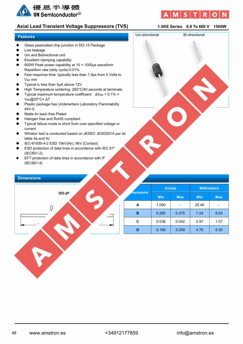
48
Axial Lead Transient Voltage Suppressors (TVS) 1.5KE Series 6.8 To 600 V 1500WDO-214AC(SMA) Uni-directional Bi-directional
Glass passivated chip junction in DO-15 Package Low leakage Uni and Bidirectional unit Excellent clamping capability 600W Peak power capability at 10 × 1000µs waveform
Repetition rate (duty cycle):0.01% Fast response time: typically less than 1.0ps from 0 Volts to
VBR min Typical IR less than 5μA above 12V. High Temperature soldering: 260°C/40 seconds at terminals Typical maximum temperature coefficient ΔVBR = 0.1% ×
VBR@25°C× ΔT Plastic package has Underwriters Laboratory Flammability
94V-0 Matte tin lead–free Plated Halogen free and RoHS compliant Typical failure mode is short from over-specified voltage or
current Whisker test is conducted based on JEDEC JESD201A per its
table 4a and 4c IEC-61000-4-2 ESD 15kV(Air), 8kV (Contact) ESD protection of data lines in accordance with IEC 61000-4-2
(IEC801-2) EFT protection of data lines in accordance with IEC 61000-4-4
(IEC801-4)
DO-201
DimensionsInches Millimeters
Min Max Min Max
A 1.000 - 25.40 -
B 0.285 0.375 7.24 9.53
C 0.038 0.042 0.97 1.07
D 0.189 0.209 4.79 5.30
Dimensions
DO-201
Cathode Band
Features
www.amstron.es +34912177859 [email protected]
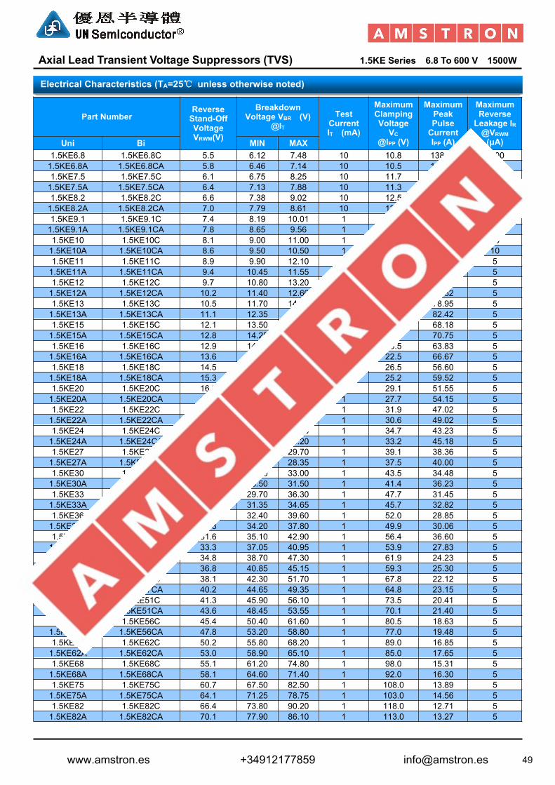
49
Axial Lead Transient Voltage Suppressors (TVS) 1.5KE Series 6.8 To 600 V 1500WDO-214AC(SMA)
Part NumberReverseStand-OffVoltageVRWM(V)
BreakdownVoltage VBR (V)
@ITTest
CurrentIT (mA)
MaximumClampingVoltage
VC@IPP (V)
MaximumPeakPulseCurrentIPP (A)
MaximumReverseLeakage IR@VRWM(μA)Uni Bi MIN MAX
1.5KE6.8 1.5KE6.8C 5.5 6.12 7.48 10 10.8 138.89 10001.5KE6.8A 1.5KE6.8CA 5.8 6.46 7.14 10 10.5 142.86 10001.5KE7.5 1.5KE7.5C 6.1 6.75 8.25 10 11.7 128.21 5001.5KE7.5A 1.5KE7.5CA 6.4 7.13 7.88 10 11.3 132.74 5001.5KE8.2 1.5KE8.2C 6.6 7.38 9.02 10 12.5 120.00 2001.5KE8.2A 1.5KE8.2CA 7.0 7.79 8.61 10 12.1 123.97 2001.5KE9.1 1.5KE9.1C 7.4 8.19 10.01 1 13.8 108.70 501.5KE9.1A 1.5KE9.1CA 7.8 8.65 9.56 1 13.4 111.94 501.5KE10 1.5KE10C 8.1 9.00 11.00 1 15.0 100.00 101.5KE10A 1.5KE10CA 8.6 9.50 10.50 1 14.5 103.45 101.5KE11 1.5KE11C 8.9 9.90 12.10 1 16.2 92.59 51.5KE11A 1.5KE11CA 9.4 10.45 11.55 1 15.6 96.15 51.5KE12 1.5KE12C 9.7 10.80 13.20 1 17.3 86.71 51.5KE12A 1.5KE12CA 10.2 11.40 12.60 1 16.7 89.82 51.5KE13 1.5KE13C 10.5 11.70 14.30 1 19.0 78.95 51.5KE13A 1.5KE13CA 11.1 12.35 13.65 1 18.2 82.42 51.5KE15 1.5KE15C 12.1 13.50 16.50 1 22.0 68.18 51.5KE15A 1.5KE15CA 12.8 14.25 15.75 1 21.2 70.75 51.5KE16 1.5KE16C 12.9 14.40 17.60 1 23.5 63.83 51.5KE16A 1.5KE16CA 13.6 15.20 16.80 1 22.5 66.67 51.5KE18 1.5KE18C 14.5 16.20 19.80 1 26.5 56.60 51.5KE18A 1.5KE18CA 15.3 17.10 18.90 1 25.2 59.52 51.5KE20 1.5KE20C 16.2 18.00 22.00 1 29.1 51.55 51.5KE20A 1.5KE20CA 17.1 19.00 21.00 1 27.7 54.15 51.5KE22 1.5KE22C 17.8 19.80 24.20 1 31.9 47.02 51.5KE22A 1.5KE22CA 18.8 20.90 23.10 1 30.6 49.02 51.5KE24 1.5KE24C 19.4 21.60 26.40 1 34.7 43.23 51.5KE24A 1.5KE24CA 20.5 22.80 25.20 1 33.2 45.18 51.5KE27 1.5KE27C 21.8 24.30 29.70 1 39.1 38.36 51.5KE27A 1.5KE27CA 23.1 25.65 28.35 1 37.5 40.00 51.5KE30 1.5KE30C 24.3 27.00 33.00 1 43.5 34.48 51.5KE30A 1.5KE30CA 25.6 28.50 31.50 1 41.4 36.23 51.5KE33 1.5KE33C 26.8 29.70 36.30 1 47.7 31.45 51.5KE33A 1.5KE33CA 28.2 31.35 34.65 1 45.7 32.82 51.5KE36 1.5KE36C 29.1 32.40 39.60 1 52.0 28.85 51.5KE36A 1.5KE36CA 30.8 34.20 37.80 1 49.9 30.06 51.5KE39 1.5KE39C 31.6 35.10 42.90 1 56.4 36.60 51.5KE39A 1.5KE39CA 33.3 37.05 40.95 1 53.9 27.83 51.5KE43 1.5KE43C 34.8 38.70 47.30 1 61.9 24.23 51.5KE43A 1.5KE43CA 36.8 40.85 45.15 1 59.3 25.30 51.5KE47 1.5KE47C 38.1 42.30 51.70 1 67.8 22.12 51.5KE47A 1.5KE47CA 40.2 44.65 49.35 1 64.8 23.15 51.5KE51 1.5KE51C 41.3 45.90 56.10 1 73.5 20.41 51.5KE51A 1.5KE51CA 43.6 48.45 53.55 1 70.1 21.40 51.5KE56 1.5KE56C 45.4 50.40 61.60 1 80.5 18.63 51.5KE56A 1.5KE56CA 47.8 53.20 58.80 1 77.0 19.48 51.5KE62 1.5KE62C 50.2 55.80 68.20 1 89.0 16.85 51.5KE62A 1.5KE62CA 53.0 58.90 65.10 1 85.0 17.65 51.5KE68 1.5KE68C 55.1 61.20 74.80 1 98.0 15.31 51.5KE68A 1.5KE68CA 58.1 64.60 71.40 1 92.0 16.30 51.5KE75 1.5KE75C 60.7 67.50 82.50 1 108.0 13.89 51.5KE75A 1.5KE75CA 64.1 71.25 78.75 1 103.0 14.56 51.5KE82 1.5KE82C 66.4 73.80 90.20 1 118.0 12.71 51.5KE82A 1.5KE82CA 70.1 77.90 86.10 1 113.0 13.27 5
Electrical Characteristics (TA=25℃ unless otherwise noted)
www.amstron.es +34912177859 [email protected]

50
Axial Lead Transient Voltage Suppressors (TVS) 1.5KE Series 6.8 To 600 V 1500WDO-214AC(SMA)
Part NumberReverseStand-OffVoltageVRWM(V)
BreakdownVoltage VBR (V)
@ITTest
CurrentIT (mA)
MaximumClampingVoltage
VC@IPP (V)
MaximumPeakPulseCurrentIPP (A)
MaximumReverseLeakage IR@VRWM(μA)Uni Bi MIN MAX
1.5KE91 1.5KE91C 73.7 81.90 100.10 1 131.0 11.45 51.5KE91A 1.5KE91CA 77.8 86.45 95.55 1 125.0 12.00 51.5KE100 1.5KE100C 81.0 90.00 110.00 1 144.0 10.42 51.5KE100A 1.5KE100CA 85.5 95.00 105.00 1 137.0 10.95 51.5KE110 1.5KE110C 89.2 99.00 121.00 1 158.0 9.49 51.5KE110A 1.5KE110CA 94.0 104.50 115.50 1 152.0 9.87 51.5KE120 1.5KE120C 97.2 108.00 132.00 1 173.0 8.67 51.5KE120A 1.5KE120CA 102.0 114.00 126.00 1 165.0 9.09 51.5KE130 1.5KE130C 105.0 117.00 143.00 1 187.0 8.02 51.5KE130A 1.5KE130CA 111.0 123.50 136.50 1 179.0 8.38 51.5KE150 1.5KE150C 121.0 135.00 165.00 1 215.0 6.98 51.5KE150A 1.5KE150CA 128.0 142.50 157.50 1 207.0 7.25 51.5KE160 1.5KE160C 130.0 144.00 176.00 1 230.0 6.52 51.5KE160A 1.5KE160CA 136.0 152.00 168.00 1 219.0 6.85 51.5KE170 1.5KE170C 138.0 153.00 187.00 1 244.0 6.15 51.5KE170A 1.5KE170CA 145.0 161.50 178.50 1 234.0 6.41 51.5KE180 1.5KE180C 146.0 162.00 198.00 1 258.0 5.81 51.5KE180A 1.5KE180CA 154.0 171.00 189.00 1 246.0 6.10 51.5KE200 1.5KE200C 162.0 180.00 220.00 1 287.0 5.23 51.5KE200A 1.5KE200CA 171.0 190.00 210.00 1 274.0 5.47 51.5KE220 1.5KE220C 175.0 198.00 242.00 1 344.0 4.36 51.5KE220A 1.5KE220CA 185.0 209.00 231.00 1 328.0 4.57 51.5KE250 1.5KE250C 202.0 225.00 275.00 1 360.0 4.17 51.5KE250A 1.5KE250CA 214.0 237.50 262.50 1 344.0 4.36 51.5KE300 1.5KE300C 243.0 270.00 330.00 1 430.0 3.49 51.5KE300A 1.5KE300CA 256.0 285.00 315.00 1 414.0 3.62 51.5KE350 1.5KE350C 284.0 315.00 385.00 1 504.0 2.98 51.5KE350A 1.5KE350CA 299.3 332.50 367.50 1 482.0 3.11 51.5KE380 1.5KE380C 308.6 342.00 418.00 1 547.2 2.74 51.5KE380A 1.5KE380CA 324.9 361.00 399.00 1 524.4 2.86 51.5KE400 1.5KE400C 324.8 360.00 440.00 1 576.0 2.60 51.5KE400A 1.5KE400CA 342.0 380.00 420.00 1 552.0 2.72 51.5KE440 1.5KE440C 357.3 396.00 484.00 1 633.6 2.37 51.5KE440A 1.5KE440CA 376.2 418.00 462.00 1 607.2 2.47 51.5KE500 1.5KE500C 406.0 450.00 550.00 1 720.0 2.08 51.5KE500A 1.5KE500CA 427.5 475.00 525.00 1 690.0 2.17 51.5KE520 1.5KE520C 422.2 468.00 572.00 1 748.8 2.00 51.5KE520A 1.5KE520CA 444.6 494.00 546.00 1 717.6 2.09 51.5KE550 1.5KE550C 446.6 495.00 605.00 1 792.0 1.89 51.5KE550A 1.5KE550CA 470.3 522.50 577.50 1 759.0 1.98 51.5KE600 1.5KE600C 487.2 540.00 660.00 1 864.0 1.74 51.5KE600A 1.5KE600CA 513.0 570.00 630.00 1 828.0 1.81 5
Note:1. Suffix 'A ' denotes 5% tolerance device. Without 'A' denotes 10% tolerance device2. Add suffix 'C 'or ' CA ' after part number to specify Bi-directional devices3. For Bi-Directional devices having VR of 10 volts and under, the IR limit is double
Electrical Characteristics (TA=25℃ unless otherwise noted)
www.amstron.es +34912177859 [email protected]

51
Axial Lead Transient Voltage Suppressors (TVS) 3KP Series 5.0 To 190 V 3000W
Uni-directional Bi-directional
Glass passivated chip junction in P600 Package Low leakage Uni and Bidirectional unit Excellent clamping capability 3000W Peak power capability at 10 × 1000µs waveform
Repetition rate (duty cycle):0.01% Fast response time: typically less than 1.0ps from 0 Volts to
VBR min Typical IR less than 5μA above 12V. High Temperature soldering: 260°C/40 seconds at terminals Typical maximum temperature coefficient ΔVBR = 0.1% ×
VBR@25°C× ΔT Plastic package has Underwriters Laboratory Flammability
94V-0 Matte tin lead–free Plated Halogen free and RoHS compliant Typical failure mode is short from over-specified voltage or
current Whisker test is conducted based on JEDEC JESD201A per its
table 4a and 4c IEC-61000-4-2 ESD 15kV(Air), 8kV (Contact) ESD protection of data lines in accordance with IEC 61000-4-2
(IEC801-2) EFT protection of data lines in accordance with IEC 61000-4-4
(IEC801-4)
R6/P600
DimensionsInches Millimeters
Min Max Min Max
A 1.000 - 25.40 -
B 0.340 0.360 8.64 9.14
C 0.048 0.052 1.22 1.32
D 0.340 0.360 8.64 9.14
Features
Dimensions
R6/P600
Cathode Band
www.amstron.es +34912177859 [email protected]

52
Axial Lead Transient Voltage Suppressors (TVS) 3KP Series 5.0 To 190 V 3000W
Part NumberReverseStand-OffVoltageVRWM(V)
BreakdownVoltage VBR (V)
@IT
TestCurrentIT (mA)
MaximumClampingVoltage
VC@IPP (V)
MaximumPeakPulseCurrentIPP (A)
MaximumReverseLeakage IR@VRWM(μA)Uni Bi MIN MAX
3KP5.0 3KP5.0C 5.0 6.40 7.30 50 9.6 312.50 10003KP5.0A 3KP5.0CA 5.0 6.40 7.00 50 9.2 326.09 10003KP6.0 3KP6.0C 6.0 6.67 8.15 50 11.4 263.16 10003KP6.0A 3KP6.0CA 6.0 6.67 7.37 50 10.3 291.26 10003KP6.5 3KP6.5C 6.5 7.22 8.82 50 12.3 243.90 5003KP6.5A 3KP6.5CA 6.5 7.22 7.98 50 11.2 267.86 5003KP7.0 3KP7.0C 7.0 7.78 9.51 50 13.3 225.56 2003KP7.0A 3KP7.0CA 7.0 7.78 8.60 50 12.0 250.00 2003KP7.5 3KP7.5C 7.5 8.33 10.20 5 14.3 209.79 1003KP7.5A 3KP7.5CA 7.5 8.33 9.21 5 12.9 232.56 1003KP8.0 3KP8.0C 8.0 8.89 10.90 5 15.0 200.00 503KP8.0A 3KP8.0CA 8.0 8.89 9.83 5 13.6 220.59 503KP8.5 3KP8.5C 8.5 9.44 11.50 5 15.9 188.68 253KP8.5A 3KP8.5CA 8.5 9.44 10.40 5 14.4 208.33 253KP9.0 3KP9.0C 9.0 10.00 12.20 5 16.9 177.51 103KP9.0A 3KP9.0CA 9.0 10.00 11.10 5 15.4 194.81 103KP10 3KP10C 10.0 11.10 13.60 5 18.8 159.57 53KP10A 3KP10CA 10.0 11.10 12.30 5 17.0 176.47 53KP11 3KP11C 11.0 12.20 14.90 5 20.1 149.25 53KP11A 3KP11CA 11.0 12.20 13.50 5 18.2 164.84 53KP12 3KP12C 12.0 13.30 16.30 5 22.0 136.36 53KP12A 3KP12CA 12.0 13.30 14.70 5 19.9 150.75 53KP13 3KP13C 13.0 14.40 17.60 5 23.8 126.05 53KP13A 3KP13CA 13.0 14.40 15.90 5 21.5 139.53 53KP14 3KP14C 14.0 15.60 19.10 5 25.8 116.28 53KP14A 3KP14CA 14.0 15.60 17.20 5 23.2 129.31 53KP15 3KP15C 15.0 16.70 20.40 5 26.9 111.52 53KP15A 3KP15CA 15.0 16.70 18.50 5 24.4 122.95 53KP16 3KP16C 16.0 17.80 21.80 5 28.8 104.17 53KP16A 3KP16CA 16.0 17.80 19.70 5 26.0 115.38 53KP17 3KP17C 17.0 18.90 23.10 5 30.5 98.36 53KP17A 3KP17CA 17.0 18.90 20.90 5 27.6 108.70 53KP18 3KP18C 18.0 20.00 24.40 5 32.2 93.17 53KP18A 3KP18CA 18.0 20.00 22.10 5 29.2 102.74 53KP19 3KP19C 19.0 21.13 25.76 5 34.0 88.21 53KP19A 3KP19CA 19.0 21.10 23.30 5 30.8 97.47 53KP20 3KP20C 20.0 22.20 27.10 5 35.8 83.80 53KP20A 3KP20CA 20.0 22.20 24.50 5 32.4 92.59 53KP22 3KP22C 22.0 24.40 29.80 5 39.4 76.14 53KP22A 3KP22CA 22.0 24.40 26.90 5 35.5 84.51 53KP24 3KP24C 24.0 26.70 32.60 5 43.0 69.77 53KP24A 3KP24CA 24.0 26.70 29.50 5 38.9 77.12 53KP26 3KP26C 26.0 28.90 35.30 5 46.6 64.38 53KP26A 3KP26CA 26.0 28.90 31.90 5 42.1 71.26 53KP28 3KP28C 28.0 31.10 38.00 5 50.0 60.00 53KP28A 3KP28CA 28.0 31.10 34.40 5 45.4 66.08 53KP30 3KP30C 30.0 33.30 40.70 5 53.5 56.07 53KP30A 3KP30CA 30.0 33.30 36.80 5 48.4 61.98 53KP33 3KP33C 33.0 36.70 44.90 5 59.0 50.85 53KP33A 3KP33CA 33.0 36.70 40.60 5 53.3 56.29 53KP36 3KP36C 36.0 40.00 48.90 5 64.3 46.66 53KP36A 3KP36CA 36.0 40.00 44.20 5 58.1 51.64 53KP40 3KP40C 40.0 44.40 54.30 5 71.4 42.02 53KP40A 3KP40CA 40.0 44.40 49.10 5 64.5 46.51 53KP43 3KP43C 43.0 47.80 58.40 5 76.7 39.11 53KP43A 3KP43CA 43.0 47.80 52.80 5 69.4 43.23 5
Electrical Characteristics (TA=25℃ unless otherwise noted)
www.amstron.es +34912177859 [email protected]

53
Axial Lead Transient Voltage Suppressors (TVS) 3KP Series 5.0 To 190 V 3000W
Part NumberReverseStand-OffVoltageVRWM(V)
BreakdownVoltage VBR (V)
@ITTest
CurrentIT (mA)
MaximumClampingVoltage
VC@IPP (V)
MaximumPeakPulseCurrentIPP (A)
MaximumReverseLeakage IR@VRWM(μA)Uni Bi MIN MAX
3KP45 3KP45C 45.0 50.00 61.10 5 80.3 37.36 53KP45A 3KP45CA 45.0 50.00 55.30 5 72.7 41.27 53KP48 3KP48C 48.0 53.30 65.10 5 85.5 35.09 53KP48A 3KP48CA 48.0 53.30 58.90 5 77.4 38.76 53KP51 3KP51C 51.0 56.70 69.30 5 91.1 32.93 53KP51A 3KP51CA 51.0 56.70 62.70 5 82.4 36.41 53KP54 3KP54C 54.0 60.00 73.30 5 96.3 31.15 53KP54A 3KP54CA 54.0 60.00 66.30 5 87.1 34.44 53KP58 3KP58C 58.0 64.40 78.70 5 103.0 29.13 53KP58A 3KP58CA 58.0 64.40 71.20 5 93.6 32.05 53KP60 3KP60C 60.0 66.70 81.50 5 107.0 28.04 53KP60A 3KP60CA 60.0 66.70 73.70 5 96.8 30.99 53KP64 3KP64C 64.0 71.10 86.90 5 114.0 26.32 53KP64A 3KP64CA 64.0 71.10 78.60 5 103.0 29.13 53KP70 3KP70C 70.0 77.80 95.10 5 125.0 24.00 53KP70A 3KP70CA 70.0 77.80 86.00 5 113.0 26.55 53KP75 3KP75C 75.0 83.30 102.00 5 134.0 22.39 53KP75A 3KP75CA 75.0 83.30 92.10 5 121.0 24.79 53KP78 3KP78C 78.0 86.70 106.00 5 139.0 21.58 53KP78A 3KP78CA 78.0 86.70 95.80 5 126.0 23.81 53KP80 3KP80C 80.0 88.96 108.80 5 143.2 20.95 53KP80A 3KP80CA 80.0 88.80 97.60 5 129.6 23.15 53KP85 3KP85C 85.0 94.40 115.00 5 151.0 19.87 53KP85A 3KP85CA 85.0 94.40 104.00 5 137.0 21.90 53KP90 3KP90C 90.0 100.00 122.00 5 160.0 18.75 53KP90A 3KP90CA 90.0 100.00 111.00 5 146.0 20.55 53KP100 3KP100C 100.0 111.00 136.00 5 179.0 16.76 53KP100A 3KP100CA 100.0 111.00 123.00 5 162.0 18.52 53KP110 3KP110C 110.0 122.00 149.00 5 196.0 15.31 53KP110A 3KP110CA 110.0 122.00 135.00 5 177.0 16.95 53KP120 3KP120C 120.0 133.00 163.00 5 214.0 14.02 53KP120A 3KP120CA 120.0 133.00 147.00 5 193.0 15.54 53KP130 3KP130C 130.0 144.00 176.00 5 231.0 12.99 53KP130A 3KP130CA 130.0 144.00 159.00 5 209.0 14.35 53KP140 3KP140C 140.0 155.68 190.40 5 250.6 11.97 53KP140A 3KP140CA 140.0 155.00 171.00 5 226.8 13.23 53KP150 3KP150C 150.0 167.00 204.00 5 268.0 11.19 53KP150A 3KP150CA 150.0 167.00 185.00 5 243.0 12.35 53KP160 3KP160C 160.0 178.00 218.00 5 287.0 10.45 53KP160A 3KP160CA 160.0 178.00 197.00 5 259.0 11.58 53KP170 3KP170C 170.0 189.00 231.00 5 304.0 9.87 53KP170A 3KP170CA 170.0 189.00 209.00 5 275.0 10.91 53KP180 3KP180C 180.0 201.00 244.80 5 322.2 9.31 53KP180A 3KP180CA 180.0 201.00 220.00 5 291.6 10.29 53KP190 3KP190C 190.0 211.21 258.40 5 340.1 8.82 53KP190A 3KP190CA 190.0 211.00 232.00 5 307.8 9.75 5
Note:1. Suffix 'A ' denotes 5% tolerance device. Without 'A' denotes 10% tolerance device2. Add suffix 'C 'or ' CA ' after part number to specify Bi-directional devices3. For Bi-Directional devices having VR of 10 volts and under, the IR limit is double
Electrical Characteristics (TA=25℃ unless otherwise noted)
www.amstron.es +34912177859 [email protected]

54
Axial Lead Transient Voltage Suppressors (TVS) 5KP Series 5.0 To 190 V 5000W
Uni-directional Bi-directional
Glass passivated chip junction in P600 Package Low leakage Uni and Bidirectional unit Excellent clamping capability 5000W Peak power capability at 10 × 1000µs waveform
Repetition rate (duty cycle):0.01% Fast response time: typically less than 1.0ps from 0 Volts to
VBR min Typical IR less than 5μA above 12V. High Temperature soldering: 260°C/40 seconds at terminals Typical maximum temperature coefficient ΔVBR = 0.1% ×
VBR@25°C× ΔT Plastic package has Underwriters Laboratory Flammability
94V-0 Matte tin lead–free Plated Halogen free and RoHS compliant Typical failure mode is short from over-specified voltage or
current Whisker test is conducted based on JEDEC JESD201A per its
table 4a and 4c IEC-61000-4-2 ESD 15kV(Air), 8kV (Contact) ESD protection of data lines in accordance with IEC 61000-4-2
(IEC801-2) EFT protection of data lines in accordance with IEC 61000-4-4
(IEC801-4)
R6/P600
DimensionsInches Millimeters
Min Max Min Max
A 1.000 - 25.40 -
B 0.340 0.360 8.64 9.14
C 0.048 0.052 1.22 1.32
D 0.340 0.360 8.64 9.14
Features
Dimensions
R6/P600
Cathode Band
www.amstron.es +34912177859 [email protected]

55
Axial Lead Transient Voltage Suppressors (TVS) 5KP Series 5.0 To 190 V 5000W
Part NumberReverseStand-OffVoltageVRWM(V)
BreakdownVoltage VBR (V)
@IT
TestCurrentIT (mA)
MaximumClampingVoltage
VC@IPP (V)
MaximumPeakPulseCurrentIPP (A)
MaximumReverseLeakage IR@VRWM(μA)Uni Bi MIN MAX
5KP5.0 5KP5.0C 5.0 6.40 7.30 10 9.6 520.83 8005KP5.0A 5KP5.0CA 5.0 6.40 7.00 10 9.2 543.48 8005KP6.0 5KP6.0C 6.0 6.67 8.15 10 11.4 438.60 8005KP6.0A 5KP6.0CA 6.0 6.67 7.37 10 10.3 485.44 8005KP6.5 5KP6.5C 6.5 7.22 8.82 10 12.3 406.50 5005KP6.5A 5KP6.5CA 6.5 7.22 7.98 10 11.2 446.43 5005KP7.0 5KP7.0C 7.0 7.78 9.51 10 13.3 375.94 2005KP7.0A 5KP7.0CA 7.0 7.78 8.60 10 12.0 416.67 2005KP7.5 5KP7.5C 7.5 8.33 10.20 1 14.3 349.65 1005KP7.5A 5KP7.5CA 7.5 8.33 9.21 1 12.9 387.60 1005KP8.0 5KP8.0C 8.0 8.89 10.90 1 15.0 333.33 505KP8.0A 5KP8.0CA 8.0 8.89 9.83 1 13.6 367.65 505KP8.5 5KP8.5C 8.5 9.44 11.50 1 15.9 314.47 205KP8.5A 5KP8.5CA 8.5 9.44 10.40 1 14.4 347.22 205KP9.0 5KP9.0C 9.0 10.00 12.20 1 16.9 295.86 105KP9.0A 5KP9.0CA 9.0 10.00 11.10 1 15.4 324.68 105KP10 5KP10C 10.0 11.10 13.60 1 18.8 265.96 55KP10A 5KP10CA 10.0 11.10 12.30 1 17.0 294.12 55KP11 5KP11C 11.0 12.20 14.90 1 20.1 248.76 55KP11A 5KP11CA 11.0 12.20 13.50 1 18.2 274.73 55KP12 5KP12C 12.0 13.30 16.30 1 22.0 227.27 55KP12A 5KP12CA 12.0 13.30 14.70 1 19.9 251.26 55KP13 5KP13C 13.0 14.40 17.60 1 23.8 210.08 55KP13A 5KP13CA 13.0 14.40 15.90 1 21.5 232.56 55KP14 5KP14C 14.0 15.60 19.10 1 25.8 193.80 55KP14A 5KP14CA 14.0 15.60 17.20 1 23.2 215.52 55KP15 5KP15C 15.0 16.70 20.40 1 26.9 185.87 55KP15A 5KP15CA 15.0 16.70 18.50 1 24.4 204.92 55KP16 5KP16C 16.0 17.80 21.80 1 28.8 173.61 55KP16A 5KP16CA 16.0 17.80 19.70 1 26.0 192.31 55KP17 5KP17C 17.0 18.90 23.10 1 30.5 163.93 55KP17A 5KP17CA 17.0 18.90 20.90 1 27.6 181.16 55KP18 5KP18C 18.0 20.00 24.40 1 32.2 155.28 55KP18A 5KP18CA 18.0 20.00 22.10 1 29.2 171.23 55KP19 5KP19C 19.0 21.13 25.76 1 34.0 147.02 55KP19A 5KP19CA 19.0 21.10 23.30 1 30.8 162.44 55KP20 5KP20C 20.0 22.20 27.10 1 35.8 139.66 55KP20A 5KP20CA 20.0 22.20 24.50 1 32.4 154.32 55KP22 5KP22C 22.0 24.40 29.80 1 39.4 126.90 55KP22A 5KP22CA 22.0 24.40 26.90 1 35.5 140.85 55KP24 5KP24C 24.0 26.70 32.60 1 43.0 116.28 55KP24A 5KP24CA 24.0 26.70 29.50 1 38.9 128.53 55KP26 5KP26C 26.0 28.90 35.30 1 46.6 107.30 55KP26A 5KP26CA 26.0 28.90 31.90 1 42.1 118.76 55KP28 5KP28C 28.0 31.10 38.00 1 50.0 100.00 55KP28A 5KP28CA 28.0 31.10 34.40 1 45.4 110.13 55KP30 5KP30C 30.0 33.30 40.70 1 53.5 93.46 55KP30A 5KP30CA 30.0 33.30 36.80 1 48.4 103.31 55KP33 5KP33C 33.0 36.70 44.90 1 59.0 84.75 55KP33A 5KP33CA 33.0 36.70 40.60 1 53.3 93.81 55KP36 5KP36C 36.0 40.00 48.90 1 64.3 77.76 55KP36A 5KP36CA 36.0 40.00 44.20 1 58.1 86.06 55KP40 5KP40C 40.0 44.40 54.30 1 71.4 70.03 55KP40A 5KP40CA 40.0 44.40 49.10 1 64.5 77.52 55KP43 5KP43C 43.0 47.80 58.40 1 76.7 65.19 55KP43A 5KP43CA 43.0 47.80 52.80 1 69.4 72.05 5
Electrical Characteristics (TA=25℃ unless otherwise noted)
www.amstron.es +34912177859 [email protected]

56
Axial Lead Transient Voltage Suppressors (TVS) 5KP Series 5.0 To 190 V 5000W
Part NumberReverseStand-OffVoltageVRWM(V)
BreakdownVoltage VBR (V)
@ITTest
CurrentIT (mA)
MaximumClampingVoltage
VC@IPP (V)
MaximumPeakPulseCurrentIPP (A)
MaximumReverseLeakage IR@VRWM(μA)Uni Bi MIN MAX
5KP45 5KP45C 45.0 50.00 61.10 1 80.3 62.27 55KP45A 5KP45CA 45.0 50.00 55.30 1 72.7 68.78 55KP48 5KP48C 48.0 53.30 65.10 1 85.5 58.48 55KP48A 5KP48CA 48.0 53.30 58.90 1 77.4 64.60 55KP51 5KP51C 51.0 56.70 69.30 1 91.1 54.88 55KP51A 5KP51CA 51.0 56.70 62.70 1 82.4 60.68 55KP54 5KP54C 54.0 60.00 73.30 1 96.3 51.92 55KP54A 5KP54CA 54.0 60.00 66.30 1 87.1 57.41 55KP58 5KP58C 58.0 64.40 78.70 1 103.0 48.54 55KP58A 5KP58CA 58.0 64.40 71.20 1 93.6 53.42 55KP60 5KP60C 60.0 66.70 81.50 1 107.0 46.73 55KP60A 5KP60CA 60.0 66.70 73.70 1 96.8 51.65 55KP64 5KP64C 64.0 71.10 86.90 1 114.0 43.86 55KP64A 5KP64CA 64.0 71.10 78.60 1 103.0 48.54 55KP70 5KP70C 70.0 77.80 95.10 1 125.0 40.00 55KP70A 5KP70CA 70.0 77.80 86.00 1 113.0 44.25 55KP75 5KP75C 75.0 83.30 102.00 1 134.0 37.31 55KP75A 5KP75CA 75.0 83.30 92.10 1 121.0 41.32 55KP78 5KP78C 78.0 86.70 106.00 1 139.0 35.97 55KP78A 5KP78CA 78.0 86.70 95.80 1 126.0 39.68 55KP80 5KP80C 80.0 88.96 108.80 1 143.2 34.92 55KP80A 5KP80CA 80.0 88.80 97.60 1 129.6 38.58 55KP85 5KP85C 85.0 94.40 115.00 1 151.0 33.11 55KP85A 5KP85CA 85.0 94.40 104.00 1 137.0 36.50 55KP90 5KP90C 90.0 100.00 122.00 1 160.0 31.25 55KP90A 5KP90CA 90.0 100.00 111.00 1 146.0 34.25 55KP100 5KP100C 100.0 111.00 136.00 1 179.0 27.93 55KP100A 5KP100CA 100.0 111.00 123.00 1 162.0 30.86 55KP110 5KP110C 110.0 122.00 149.00 1 196.0 25.51 55KP110A 5KP110CA 110.0 122.00 135.00 1 177.0 28.25 55KP120 5KP120C 120.0 133.00 163.00 1 214.0 23.36 55KP120A 5KP120CA 120.0 133.00 147.00 1 193.0 25.91 55KP130 5KP130C 130.0 144.00 176.00 1 231.0 21.65 55KP130A 5KP130CA 130.0 144.00 159.00 1 209.0 23.92 55KP140 5KP140C 140.0 155.68 190.40 1 250.6 19.95 55KP140A 5KP140CA 140.0 155.00 171.00 1 226.8 22.05 55KP150 5KP150C 150.0 167.00 204.00 1 268.0 18.66 55KP150A 5KP150CA 150.0 167.00 185.00 1 243.0 20.58 55KP160 5KP160C 160.0 178.00 218.00 1 287.0 17.42 55KP160A 5KP160CA 160.0 178.00 197.00 1 259.0 19.31 55KP170 5KP170C 170.0 189.00 231.00 1 304.0 16.45 55KP170A 5KP170CA 170.0 189.00 209.00 1 275.0 18.18 55KP180 5KP180C 180.0 201.00 244.80 1 322.2 15.52 55KP180A 5KP180CA 180.0 201.00 220.00 1 291.6 17.15 55KP190 5KP190C 190.0 211.21 258.40 1 340.1 14.70 55KP190A 5KP190CA 190.0 211.00 232.00 1 307.8 16.24 5
Note:1. Suffix 'A ' denotes 5% tolerance device. Without 'A' denotes 10% tolerance device2. Add suffix 'C 'or ' CA ' after part number to specify Bi-directional devices3. For Bi-Directional devices having VR of 10 volts and under, the IR limit is double
Electrical Characteristics (TA=25℃ unless otherwise noted)
www.amstron.es +34912177859 [email protected]

57
Axial Lead Transient Voltage Suppressors (TVS) 8KP Series 24 To 43 V 8000W
Uni-directional Bi-directional
Glass passivated chip junction in P600 Package Low leakage Uni and Bidirectional unit Excellent clamping capability 8000W Peak power capability at 10 × 1000µs waveform
Repetition rate (duty cycle):0.01% Fast response time RoHS compliant
R6/P600
DimensionsInches Millimeters
Min Max Min Max
A 1.000 - 25.40 -
B 0.340 0.360 8.64 9.14
C 0.048 0.052 1.22 1.32
D 0.340 0.360 8.64 9.14
Part NumberReverseStand-OffVoltageVRWM(V)
BreakdownVoltage VBR (V)
@ITTest
CurrentIT (mA)
MaximumClampingVoltage
VC@IPP (V)
MaximumPeakPulseCurrentIPP (A)
MaximumReverseLeakage IR@VRWM(μA)Uni Bi MIN MAX
8KP24A 8KP24CA 24 26.7 29.5 1 38.9 206 58KP33A 8KP33CA 33 36.7 40.6 1 53.3 150 58KP36A 8KP36CA 36 40.0 44.2 1 58.1 148 58KP40A 8KP40CA 40 44.4 49.1 1 64.5 124 58KP43A 8KP43CA 43 47.8 52.8 1 69.4 115 5
Electrical Characteristics (TA=25℃ unless otherwise noted)
Dimensions
R6/P600
Cathode Band
Features
www.amstron.es +34912177859 [email protected]

58
Axial Lead Transient Voltage Suppressors (TVS) 15KPASeries 17 To 280 V 15000W
Uni-directional Bi-directional
Glass passivated chip junction in P600 Package Low leakage Uni and Bidirectional unit Excellent clamping capability 15000W Peak power capability at 10 × 1000µs waveform
Repetition rate (duty cycle):0.01% Fast response time: typically less than 1.0ps from 0 Volts to
VBR min Typical IR less than 5μA above 12V. High Temperature soldering: 260°C/40 seconds at terminals Typical maximum temperature coefficient ΔVBR = 0.1% ×
VBR@25°C× ΔT Plastic package has Underwriters Laboratory Flammability
94V-0 Matte tin lead–free Plated Halogen free and RoHS compliant Typical failure mode is short from over-specified voltage or
current Whisker test is conducted based on JEDEC JESD201A per its
table 4a and 4c IEC-61000-4-2 ESD 15kV(Air), 8kV (Contact) ESD protection of data lines in accordance with IEC 61000-4-2
(IEC801-2) EFT protection of data lines in accordance with IEC 61000-4-4
(IEC801-4)
R6/P600
DimensionsInches Millimeters
Min Max Min Max
A 1.000 - 25.40 -
B 0.340 0.360 8.64 9.14
C 0.048 0.052 1.22 1.32
D 0.340 0.360 8.64 9.14
Features
Dimensions
R6/P600
Cathode Band
www.amstron.es +34912177859 [email protected]
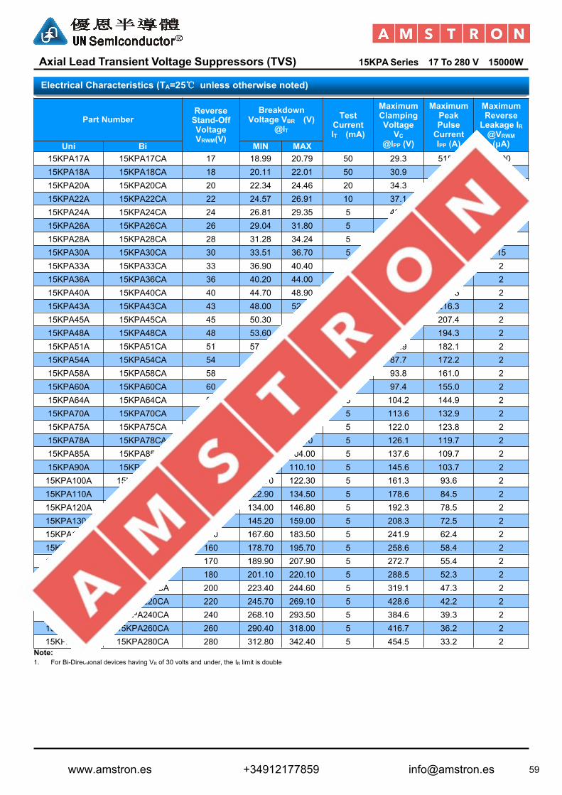
59
Axial Lead Transient Voltage Suppressors (TVS) 15KPASeries 17 To 280 V 15000W
Part NumberReverseStand-OffVoltageVRWM(V)
BreakdownVoltage VBR (V)
@ITTest
CurrentIT (mA)
MaximumClampingVoltage
VC@IPP (V)
MaximumPeakPulseCurrentIPP (A)
MaximumReverseLeakage IR@VRWM(μA)Uni Bi MIN MAX
15KPA17A 15KPA17CA 17 18.99 20.79 50 29.3 515.4 500015KPA18A 15KPA18CA 18 20.11 22.01 50 30.9 488.7 500015KPA20A 15KPA20CA 20 22.34 24.46 20 34.3 440.2 150015KPA22A 15KPA22CA 22 24.57 26.91 10 37.1 407.0 50015KPA24A 15KPA24CA 24 26.81 29.35 5 40.7 371.0 15015KPA26A 15KPA26CA 26 29.04 31.80 5 44.0 343.2 5015KPA28A 15KPA28CA 28 31.28 34.24 5 47.5 317.9 2515KPA30A 15KPA30CA 30 33.51 36.70 5 50.7 297.8 1515KPA33A 15KPA33CA 33 36.90 40.40 5 54.7 276.1 215KPA36A 15KPA36CA 36 40.20 44.00 5 59.8 252.5 215KPA40A 15KPA40CA 40 44.70 48.90 5 65.8 229.5 215KPA43A 15KPA43CA 43 48.00 52.60 5 69.8 216.3 215KPA45A 15KPA45CA 45 50.30 55.00 5 72.8 207.4 215KPA48A 15KPA48CA 48 53.60 58.70 5 77.7 194.3 215KPA51A 15KPA51CA 51 57.00 62.40 5 82.9 182.1 215KPA54A 15KPA54CA 54 60.30 66.00 5 87.7 172.2 215KPA58A 15KPA58CA 58 64.80 70.90 5 93.8 161.0 215KPA60A 15KPA60CA 60 67.00 73.40 5 97.4 155.0 215KPA64A 15KPA64CA 64 71.50 78.30 5 104.2 144.9 215KPA70A 15KPA70CA 70 78.20 85.60 5 113.6 132.9 215KPA75A 15KPA75CA 75 83.80 91.70 5 122.0 123.8 215KPA78A 15KPA78CA 78 87.10 95.40 5 126.1 119.7 215KPA85A 15KPA85CA 85 94.90 104.00 5 137.6 109.7 215KPA90A 15KPA90CA 90 100.50 110.10 5 145.6 103.7 215KPA100A 15KPA100CA 100 111.70 122.30 5 161.3 93.6 215KPA110A 15KPA110CA 110 122.90 134.50 5 178.6 84.5 215KPA120A 15KPA120CA 120 134.00 146.80 5 192.3 78.5 215KPA130A 15KPA130CA 130 145.20 159.00 5 208.3 72.5 215KPA150A 15KPA150CA 150 167.60 183.50 5 241.9 62.4 215KPA160A 15KPA160CA 160 178.70 195.70 5 258.6 58.4 215KPA170A 15KPA170CA 170 189.90 207.90 5 272.7 55.4 215KPA180A 15KPA180CA 180 201.10 220.10 5 288.5 52.3 215KPA200A 15KPA200CA 200 223.40 244.60 5 319.1 47.3 215KPA220A 15KPA220CA 220 245.70 269.10 5 428.6 42.2 215KPA240A 15KPA240CA 240 268.10 293.50 5 384.6 39.3 215KPA260A 15KPA260CA 260 290.40 318.00 5 416.7 36.2 215KPA280A 15KPA280CA 280 312.80 342.40 5 454.5 33.2 2
Note:1. For Bi-Directional devices having VR of 30 volts and under, the IR limit is double
Electrical Characteristics (TA=25℃ unless otherwise noted)
www.amstron.es +34912177859 [email protected]

60
Axial Lead Transient Voltage Suppressors (TVS) 20KPA Series 20 To 300 V 20000W
Uni-directional Bi-directional
Glass passivated chip junction in P600 Package Low leakage Uni and Bidirectional unit Excellent clamping capability 20000W Peak power capability at 10 × 1000µs waveform
Repetition rate (duty cycle):0.01% Fast response time: typically less than 1.0ps from 0 Volts to
VBR min Typical IR less than 5μA above 12V. High Temperature soldering: 260°C/40 seconds at terminals Typical maximum temperature coefficient ΔVBR = 0.1% ×
VBR@25°C× ΔT Plastic package has Underwriters Laboratory Flammability
94V-0 Matte tin lead–free Plated Halogen free and RoHS compliant Typical failure mode is short from over-specified voltage or
current Whisker test is conducted based on JEDEC JESD201A per its
table 4a and 4c IEC-61000-4-2 ESD 15kV(Air), 8kV (Contact) ESD protection of data lines in accordance with IEC 61000-4-2
(IEC801-2) EFT protection of data lines in accordance with IEC 61000-4-4
(IEC801-4)
R6/P600
DimensionsInches Millimeters
Min Max Min Max
A 1.000 - 25.40 -
B 0.340 0.360 8.64 9.14
C 0.048 0.052 1.22 1.32
D 0.340 0.360 8.64 9.14
Features
Dimensions
R6/P600
Cathode Band
www.amstron.es +34912177859 [email protected]

61
Axial Lead Transient Voltage Suppressors (TVS) 20KPA Series 20 To 300 V 20000W
Part NumberReverseStand-OffVoltageVRWM(V)
BreakdownVoltage VBR (V)
@ITTest
CurrentIT (mA)
MaximumClampingVoltage
VC@IPP (V)
MaximumPeakPulseCurrentIPP (A)
MaximumReverseLeakage IR@VRWM(μA)Uni Bi MIN MAX
20KPA20A 20KPA20CA 20 22.34 50 36.8 548.9 5000 500020KPA24A 20KPA24CA 24 26.81 50 41.2 490.3 5000 500020KPA26A 20KPA26CA 26 29.04 50 22.7 451.9 2000 150020KPA28A 20KPA28CA 28 31.28 50 48.0 420.8 1000 50020KPA30A 20KPA30CA 30 33.51 5 51.5 392.2 250 15020KPA32A 20KPA32CA 32 35.74 5 54.3 372.0 150 5020KPA34A 20KPA34CA 34 38.00 5 57.5 351.3 50 2520KPA36A 20KPA36CA 36 40.20 5 61.5 328.5 20 1520KPA40A 20KPA40CA 40 44.70 5 67.8 297.9 15 220KPA44A 20KPA44CA 44 49.10 5 72.7 277.9 2 220KPA48A 20KPA48CA 48 53.60 5 79.4 254.4 2 220KPA52A 20KPA52CA 52 58.10 5 85.8 235.4 2 220KPA56A 20KPA56CA 56 62.60 5 92.6 218.1 2 220KPA60A 20KPA60CA 60 67.00 5 97.6 207.0 2 220KPA64A 20KPA64CA 64 71.50 5 104.0 194.2 2 220KPA68A 20KPA68CA 68 76.00 5 110.0 183.6 2 220KPA72A 20KPA72CA 72 80.40 5 116.0 174.1 2 220KPA80A 20KPA80A 80 89.40 5 130.0 155.4 2 220KPA88A 20KPA88CA 88 98.30 5 142.0 142.3 2 220KPA96A 20KPA96CA 96 107.20 5 155.0 130.3 2 220KPA104A 20KPA104CA 104 116.20 5 168.0 120.2 2 220KPA112A 20KPA112CA 112 125.10 5 182.0 111.0 2 220KPA120A 20KPA120CA 120 134.00 5 194.0 104.1 2 220KPA132A 20KPA132CA 132 147.40 5 213.0 94.8 2 220KPA144A 20KPA144CA 144 160.80 5 232.0 87.1 2 220KPA160A 20KPA160CA 160 178.70 5 258.0 78.3 2 220KPA172A 20KPA172CA 172 192.10 5 277.0 72.9 2 220KPA180A 20KPA180CA 180 201.10 5 291.0 69.4 2 220KPA192A 20KPA192CA 192 214.50 5 309.0 65.4 2 220KPA204A 20KPA204CA 204 227.90 5 329.0 61.4 2 220KPA216A 20KPA216CA 216 241.30 5 348.0 58.0 2 220KPA232A 20KPA232CA 232 159.10 5 374.0 54.0 2 220KPA240A 20KPA240CA 240 268.10 5 387.0 52.2 2 220KPA256A 20KPA256CA 256 286.00 5 412.0 49.0 2 220KPA280A 20KPA280CA 280 312.80 5 451.0 44.8 2 220KPA300A 20KPA300CA 300 335.10 5 483.0 41.8 2 2
Note:1. For Bi-Directional devices having VR of 40 volts and under, the IR limit is double
Electrical Characteristics (TA=25℃ unless otherwise noted)
www.amstron.es +34912177859 [email protected]

62
Axial Lead Transient Voltage Suppressors (TVS) 30KPA Series 28 To 288 V 30000W
Uni-directional Bi-directional
Glass passivated chip junction in P600 Package Low leakage Uni and Bidirectional unit Excellent clamping capability 30000W Peak power capability at 10 × 1000µs waveform
Repetition rate (duty cycle):0.01% Fast response time: typically less than 1.0ps from 0 Volts to
VBR min Typical IR less than 5μA above 12V. High Temperature soldering: 260°C/40 seconds at terminals Typical maximum temperature coefficient ΔVBR = 0.1% ×
VBR@25°C× ΔT Plastic package has Underwriters Laboratory Flammability
94V-0 Matte tin lead–free Plated Halogen free and RoHS compliant Typical failure mode is short from over-specified voltage or
current Whisker test is conducted based on JEDEC JESD201A per its
table 4a and 4c IEC-61000-4-2 ESD 15kV(Air), 8kV (Contact) ESD protection of data lines in accordance with IEC 61000-4-2
(IEC801-2) EFT protection of data lines in accordance with IEC 61000-4-4
(IEC801-4)
R6/P600
DimensionsInches Millimeters
Min Max Min Max
A 1.000 - 25.40 -
B 0.340 0.360 8.64 9.14
C 0.048 0.052 1.22 1.32
D 0.340 0.360 8.64 9.14
Dimensions
R6/P600
Cathode Band
Features
www.amstron.es +34912177859 [email protected]

63
Axial Lead Transient Voltage Suppressors (TVS) 30KPA Series 28 To 288 V 30000W
Part NumberReverseStand-OffVoltageVRWM(V)
BreakdownVoltage VBR
(V)@IT
TestCurrentIT (mA)
MaximumClampingVoltage VC
@IPP (V)
MaximumPeakPulseCurrentIPP (A)
MaximumReverseLeakage IR@VRWM
(μA)Uni Bi MIN30KPA28A 30KPA28CA 28 31.28 50 50.0 606.0 500030KPA30A 30KPA30CA 30 33.51 50 55.2 548.9 500030KPA33A 30KPA33CA 33 36.90 50 58.5 517.9 500030KPA36A 30KPA36CA 36 40.20 50 61.8 490.3 500030KPA39A 30KPA39CA 39 43.60 20 67.2 450.9 200030KPA42A 30KPA42CA 42 46.90 10 72.0 420.8 100030KPA43A 30KPA43CA 43 48.00 10 73.0 415.1 100030KPA45A 30KPA45CA 45 50.30 5 77.4 391.5 25030KPA48A 30KPA48CA 48 53.60 5 81.6 371.3 15030KPA51A 30KPA51CA 51 57.00 5 86.4 350.7 5030KPA54A 30KPA54CA 54 60.30 5 91.4 331.5 2030KPA58A 30KPA58CA 58 64.80 5 92.4 327.9 2030KPA60A 30KPA60CA 60 67.00 5 102.0 297.1 1530KPA64A 30KPA64CA 64 71.50 5 104.0 291.3 1030KPA66A 30KPA66CA 66 73.70 5 107.0 283.2 230KPA70A 30KPA70CA 70 78.20 5 109.0 278.0 230KPA71A 30KPA71CA 71 79.30 5 111.5 271.7 230KPA72A 30KPA72CA 72 80.40 5 114.0 265.8 230KPA75A 30KPA75CA 75 83.80 5 119.4 253.8 230KPA78A 30KPA78CA 78 87.10 5 129.0 234.9 230KPA84A 30KPA84CA 84 93.80 5 139.2 217.7 230KPA90A 30KPA90CA 90 100.50 5 146.4 207.0 230KPA96A 30KPA96CA 96 107.20 5 156.0 194.2 230KPA102A 30KPA102CA 102 113.90 5 165.6 183.0 230KPA108A 30KPA108CA 108 120.60 5 175.2 172.9 230KPA120A 30KPA120CA 120 134.00 5 194.4 155.9 230KPA132A 30KPA132CA 132 147.40 5 213.0 142.3 230KPA144A 30KPA144CA 144 160.80 5 223.2 135.8 230KPA150A 30KPA150CA 150 167.60 5 233.4 129.8 230KPA156A 30KPA156CA 156 174.30 5 245.0 123.7 230KPA160A 30KPA160CA 160 178.70 5 252.6 120.0 230KPA168A 30KPA168CA 168 187.70 5 272.4 111.2 230KPA170A 30KPA170CA 170 189.90 5 275.0 110.2 230KPA180A 30KPA180CA 180 201.10 5 290.4 104.3 230KPA198A 30KPA198CA 198 221.20 5 319.8 94.7 230KPA216A 30KPA216CA 216 241.30 5 348.6 86.9 230KPA240A 30KPA240CA 240 268.10 5 387.0 78.3 230KPA258A 30KPA258CA 258 188.20 5 416.4 72.8 230KPA260A 30KPA260CA 260 290.40 5 416.0 72.8 230KPA270A 30KPA270CA 270 301.60 5 436.2 69.5 230KPA280A 30KPA280CA 280 312.80 5 464.0 65.3 230KPA288A 30KPA288CA 288 321.70 5 469.9 64.5 2
Note:1. For Bi-Directional devices having VR of 40 volts and under, the IR limit is double
Electrical Characteristics (TA=25℃ unless otherwise noted)
www.amstron.es +34912177859 [email protected]

64
Radial Lead Transient Voltage Suppressors (TVS) K Series 1KA To 10KA
Axial lead terminals
High current transient suppressor
Excellent Clamping Capability
Glass Passivated Junction
Bi-directional
Low Slope Resistance
Repetition Rate (duty cycle):0.01%
Hazardous Substances Free
RoHS Compliant
High Temperature soldering: 260°C/10 seconds at terminals
Epoxy Encapsulated
Silver plated leads Solderable per MIL-STD-202 Method 208
Dimensions Inches Millimeters
A max 0.571 max 14.5
B Max0.500 max 12.7
C Φ0.051±0.004 Φ1.30±0.1
D 0.236±0.040 6.0±1.0
E 0.950±0.028 24.15±0.7
F max 0.10 max 2.5
Dimensions
Features
www.amstron.es +34912177859 [email protected]

65
Radial Lead Transient Voltage Suppressors (TVS) K Series 1KA To 15KA
Part Number
Reverse Stand-OffVoltage
BreakdownVoltage
TestCurrent
CurrentRating
MaximumEnergy
MaximumClampingVoltage
ReverseLeakage
VAC(V) VDC(V) VBR(V)MIN.@IT
IT(mA)
IPP 8/20μs(KA)
10/1000μs(A)
VC(V)@IPP
IR (μA)@VDC
K1-076 54 76 83 10 1 - 135 20KA-012 8.5 12.8 14 1 3 500 28 20KA-015 11 15 17 1 3 650 30 20KA-020 14 20 22 1 3 800 40 20KA-025 17 25 28 1 3 950 50 20KA-030 21 30 33 1 3 1200 60 20KA-042 30 42 47 1 3 1700 77 20KA-058 40 58 64 1 3 2450 110 20KA-066 45 66 70 1 3 2600 125 20KA-076 54 76 85 1 3 2800 140 20KA-100 72 100 110 1 3 4250 165 20KA-133 100 133 147 1 3 5300 220 20KA-170 130 170 180 1 3 7000 260 20KA-190 145 190 200 1 3 8400 290 20KA-200 150 200 222 1 3 8600 330 20KA-240 180 240 250 1 3 9100 340 20KB-012 8.5 12.8 14 1 6 1000 28 20KB-015 11 15 17 1 6 1300 30 20KB-020 14 20 22 1 6 1600 40 20KB-025 17 25 28 1 6 1900 50 20KB-030 21 30 33 1 6 2400 60 20KB-042 30 42 47 1 6 3400 77 20KB-058 40 58 64 1 6 4900 110 20KB-066 45 66 70 1 6 5200 125 20KB-076 54 76 83 1 6 5600 135 20KB-100 72 100 110 1 6 8500 165 20KB-133 100 133 147 1 6 10600 220 20KB-170 130 170 180 1 6 14000 260 20KB-190 145 190 200 1 6 16800 290 20KB-200 150 200 222 1 6 17200 330 20KB-240 180 240 250 1 6 18000 340 20KB-275 210 275 300 1 6 19000 435 20KB-300 230 300 330 1 6 25500 470 20KB-380 275 380 401 1 6 30000 520 20KC-012 8.5 12.8 14 1 10 1665 28 20KC-015 11 15 17 1 10 2164 30 20KC-020 14 20 22 1 10 2664 40 20KC-025 17 25 28 1 10 3163 50 20KC-030 21 30 33 1 10 3996 60 20KC-042 30 42 47 1 10 5661 77 20KC-058 40 58 64 1 10 8158 110 20KC-066 45 66 70 1 10 8658 125 20KC-076 54 76 83 1 10 9324 135 20KC-100 72 100 110 1 10 14152 165 20KC-133 100 133 147 1 10 17649 220 20KC-170 130 170 180 1 10 23310 260 20KC-190 145 190 200 1 10 27972 290 20KC-200 150 200 222 1 10 28638 330 20KD-012 8.5 12.8 14 1 15 2665 28 20KD-015 11 15 17 1 15 3464 30 20KD-020 14 20 22 1 15 4264 40 20KD-025 17 25 28 1 15 5063 50 20KD-030 21 30 33 1 15 6396 60 20KD-042 30 42 47 1 15 9061 77 20KD-058 40 58 64 1 15 13058 110 20KD-066 45 66 70 1 15 13858 125 20KD-076 54 76 85 1 15 14924 145 20
Electrical Characteristics (TA=25℃ unless otherwise noted)
www.amstron.es +34912177859 [email protected]

66
Axial Lead Transient Voltage Suppressors (TVS) SAC Series 5.0 To 50 V 500W Low Capacitance
Uni-directional
Glass passivated chip 500W peak pulse power capability with a 10/1000µs
waveform, repetitive rate (duty cycle): 0.01% Low leakage Excellent clamping capability Very fast response time RoHS compliant
DO204AC (DO-15)
DimensionsInches Millimeters
Min Max Min Max
A 0.077 0.087 1.960 2.200
B 0.171 0.191 4.350 4.850
C 0.130 0.155 3.300 3.940
D 0.084 0.096 2.130 2.440
Part NumberReverseStand-OffVoltageVRWM (V)
BreakdownVoltage VBR@IT=1.0mA
(V)
MaximumReverseLeakage
IR@VRWM(μA)
MaximumClampingVoltageVC
@IPP (V)
MaximumPeakPulseCurrentIPP (A)
MaximumJunctionCapacitance@0V(pF)
WorkingInverseBlockingVoltageVWIB(V)
InverseBlockingLeakageCurrent
IIB@VWIB(mA)
PeakInverseVoltageVPIB(V)
MIN
SAC5.0 5.0 7.60 300 10.0 44.0 50 75 1 100SAC6.0 6.0 7.90 300 11.2 41.0 50 75 1 100SAC7.0 7.0 8.33 300 12.6 38.0 50 75 1 100SAC8.0 8.0 8.89 100 13.4 36.0 50 75 1 100SAC8.5 8.5 9.44 50 14.0 34.0 50 75 1 100SAC10 10.0 11.10 5 16.3 29.0 50 75 1 100SAC12 12.0 13.30 5 19.0 25.0 50 75 1 100SAC15 15.0 16.67 5 23.6 20.0 50 75 1 100SAC18 18.0 20.00 5 28.8 15.0 50 75 1 100SAC22 22.0 24.40 5 35.4 14.0 50 75 1 100SAC26 26.0 28.90 5 42.3 11.1 50 75 1 100SAC30 30.0 33.30 5 48.6 10.0 50 75 1 100SAC36 36.0 40.00 5 60.0 8.6 50 75 1 100SAC45 45.0 50.00 5 77.0 6.8 50 150 1 200SAC50 50.0 55.50 5 88.0 5.8 50 150 1 200
Electrical Characteristics (TA=25℃ unless otherwise noted)
Dimensions
Features
DO-204AC (DO-15)
Cathode Band
www.amstron.es +34912177859 [email protected]
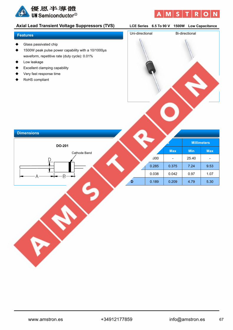
67
Axial Lead Transient Voltage Suppressors (TVS) LCE Series 6.5 To 90 V 1500W Low Capacitance
Uni-directional Bi-directional
Glass passivated chip
1500W peak pulse power capability with a 10/1000µs
waveform, repetitive rate (duty cycle): 0.01%
Low leakage
Excellent clamping capability
Very fast response time
RoHS compliant
DO-201
DimensionsInches Millimeters
Min Max Min Max
A 1.000 - 25.40 -
B 0.285 0.375 7.24 9.53
C 0.038 0.042 0.97 1.07
D 0.189 0.209 4.79 5.30
Dimensions
DO-201
Cathode Band
Features
www.amstron.es +34912177859 [email protected]

68
Axial Lead Transient Voltage Suppressors (TVS) LCE Series 6.5 To 90 V 1500W Low Capacitance
PartNumber
ReverseStand-OffVoltageVRWM (V)
BreakdownVoltage VBR
@IT(V)
TestCurrent
IT(mA)
MaximumReverseLeakage IR@VRWM(μA)
MaximumClampingVoltage VC
@IPP(V)
MaximumPeakPulseCurrentIPP (A)
MaximumJunction
Capacitance@0V(pF)
WorkingInverseBlockingVoltageVWIB(V)
InverseBlockingLeakageCurrent IIB@VWIB(mA)
PeakInverseVoltageVPIB(V)Min Max
LCE6.5 6.5 7.22 8.82 10 1000 12.3 100 100 75 1 100LCE6.5A 6.5 7.22 7.98 10 1000 11.2 100 100 75 1 100LCE7.0 7.0 7.78 9.51 10 500 13.3 100 100 75 1 100LCE7.0A 7.0 7.78 8.60 10 500 12.0 100 100 75 1 100LCE7.5 7.5 8.33 10.20 10 250 14.3 100 100 75 1 100LCE7.5A 7.5 8.33 9.21 10 250 12.9 100 100 75 1 100LCE8.0 8.0 8.89 10.90 1 100 15.0 100 100 75 1 100LCE8.0A 8.0 8.89 9.83 1 100 13.6 100 100 75 1 100LCE8.5 8.5 9.44 11.50 1 50 15.9 94 100 75 1 100LCE8.5A 8.5 9.44 10.40 1 50 14.4 100 100 75 1 100LCE9.0 9.0 10.00 12.20 1 10 16.9 89 100 75 1 100LCE9.0A 9.0 10.00 11.10 1 10 15.4 97 100 75 1 100LCE10 10.0 11.10 13.60 1 5 18.8 80 100 75 1 100LCE10A 10.0 11.10 12.30 1 5 17.0 88 100 75 1 100LCE11 11..0 12.20 14.90 1 5 20.1 74 100 75 1 100LCE11A 11.0 12.20 13.50 1 5 18.2 82 100 75 1 100LCE12 12.0 13.30 16.30 1 5 22.0 68 100 75 1 100LCE12A 12.0 13.30 14.70 1 5 19.9 75 100 75 1 100LCE13 13.0 14.40 17.60 1 5 23.8 63 100 75 1 100LCE13A 13.0 14.40 15.90 1 5 21.5 70 100 75 1 100LCE14 14.0 15.60 19.10 1 5 25.8 58 100 75 1 100LCE14A 14.0 15.60 17.20 1 5 23.2 65 100 75 1 100LCE15 15.0 16.70 20.40 1 5 26.9 56 100 75 1 100LCE15A 15.0 16.70 18.50 1 5 24.4 61 100 75 1 200LCE16 16.0 17.80 21.80 1 5 28.8 52 100 75 1 200LCE16A 16.0 17.80 19.70 1 5 26.0 57 100 75 1 200LCE17 17.0 18.90 23.10 1 5 30.5 49 100 75 1 200LCE17A 17.0 18.90 20.90 1 5 27.6 54 100 75 1 200LCE18 18.0 20.00 24.40 1 5 32.2 46 100 75 1 200LCE18A 18.0 20.00 22.10 1 5 29.2 51 100 75 1 200LCE20 20.0 22.20 27.10 1 5 35.8 42 100 75 1 200LCE20A 20.0 22.20 24.50 1 5 32.4 46 100 75 1 200LCE22 22.0 24.40 29.80 1 5 39.4 38 100 75 1 200LCE22A 22.0 24.40 26.90 1 5 35.5 42 100 75 1 200LCE24 24.0 26.70 32.60 1 5 43.0 35 100 75 1 200LCE24A 24.0 26.70 29.50 1 5 38.9 39 100 75 1 200LCE26 26.0 28.90 35.30 1 5 46.6 32 100 75 1 200LCE26A 26.0 28.90 31.90 1 5 42.1 36 100 75 1 200LCE28 28.0 31.10 38.00 1 5 50.1 30 100 75 1 200LCE28A 28.0 31.10 34.40 1 5 45.5 33 100 75 1 200LCE30A 30.0 33.30 36.80 1 5 48.4 31 100 75 1 100LCE33A 33.0 36.70 40.60 1 5 53.3 28 100 75 1 100LCE36A 36.0 40.00 44.20 1 5 58.1 26 100 75 1 100LCE40A 40.0 44.40 49.10 1 5 64.5 23 100 75 1 100LCE43A 43.0 47.80 52.80 1 5 69.4 22 100 75 1 100LCE45A 45.0 50.00 55.30 1 5 72.7 21 100 75 1 100LCE48A 48.0 53.30 58.90 1 5 77.4 19 100 75 1 100LCE51A 51.0 56.70 62.70 1 5 82.4 18 100 75 1 100LCE54A 54.0 60.00 66.30 1 5 87.1 17 100 100 1 125LCE58A 58.0 64.40 71.20 1 5 93.6 16 100 100 1 125LCE60A 60.0 66.70 73.70 1 5 96.8 16 100 100 1 125LCE64A 64.0 71.10 78.60 1 5 103.0 15 100 100 1 125LCE70A 70.0 77.80 86.00 1 5 113.0 13 100 125 1 150LCE75A 75.0 83.30 92.10 1 5 121.0 12 100 125 1 150LCE85A 85.0 94.40 104.00 1 5 129.0 12 100 125 1 150LCE90A 90.0 100.00 111.00 1 5 146.0 10 100 125 1 150
Electrical Characteristics (TA=25℃ unless otherwise noted)
www.amstron.es +34912177859 [email protected]