Embed Size (px)
Citation preview
Transistor Circuitsfor the Constructor
No. 4
E. N. BRADLEY
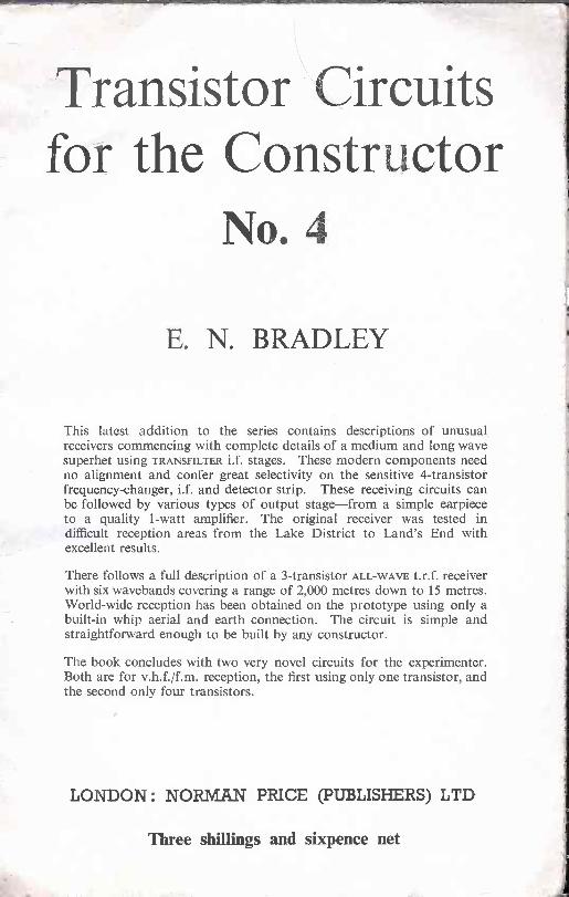
This latest addition to the series contains descriptions of unusualreceivers commencing with complete details of a medium and long wavesuperhet using TRANSFILTER i.f. stages. These modern components needno alignment and confer great selectivity on the sensitive 4 -transistorfrequency -changer, i.f. and detector strip. These receiving circuits canbe followed by various types of output stage-from a simple earpieceto a quality 1 -watt amplifier. The original receiver was tested indifficult reception areas from the Lake District to Land's End withexcellent results.
There follows a full description of a 3 -transistor ALL -WAVE t.r.f. receiverwith six wavebands covering a range of 2,000 metres down to 15 metres.World-wide reception has been obtained on the prototype using only abuilt-in whip aerial and earth connection. The circuit is simple andstraightforward enough to be built by any constructor.
The book concludes with two very novel circuits for the experimenter.Both are for v.h.f./f.m. reception, the first using only one transistor, andthe second only four transistors.
LONDON : NORMAN PRICE (PUBLISHERS) LTD
Three shillings and sixpence net
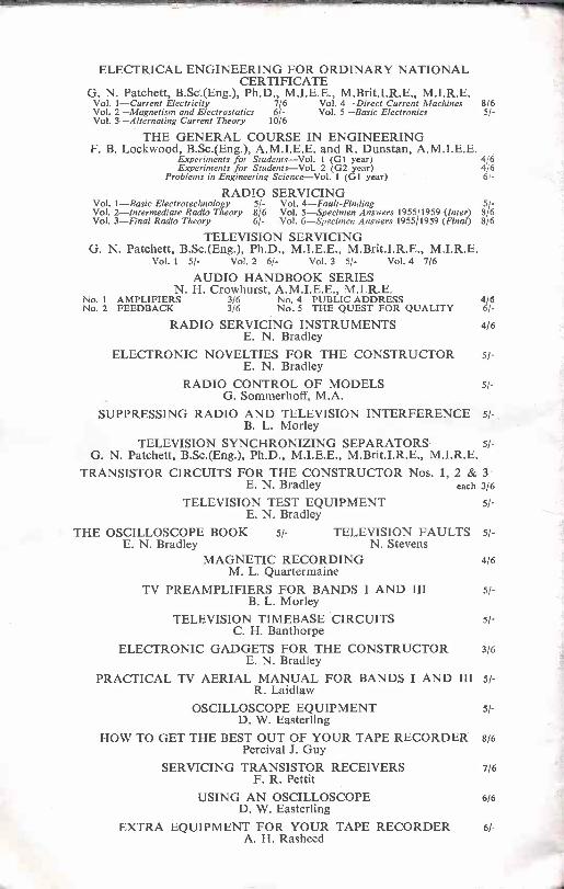
ELECTRICAL ENGINEERING FOR ORDINARY NATIONALCERTIFICATE
G. N. Patchett, B.Sc'.(Eng.), Ph.D., M.I.E.E., M.Brit.I.R.E., M.I.R.E.Vol. 1-Current Electricity 7/6 Vol. 4-Direct Current Machines 8/6Vol. 2-Magnetism and Electrostatics 6/- Vol. 5-Basic Electronics 5/ -Vol. 3-Alternating Current Theory 10/6
THE GENERAL COURSE IN ENGINEERINGF. B. Lockwood, B.Sc.(Eng.), A.M.I.E.E. and R. Dunstan, A.M.I.E.E.
Experiments for Students-Vol. 1 (61 year) 4/6Experiments for Students-Vol. 2 (62 year) 4/6
Problems in Engineering Science-Vol. 1 (61 year) 6/ -
RADIO SERVICING1-Basic Electrotechnology 5/- Vol. 4-Fault-Finding
Vol. 2-Intermediate Radio Theory 8/6 Vol. 5-Specimen Answers 1955/1959 (Inter) 85/6Vol. 3-Final Radio Theory 6/- Vol. 6-Specimen Answers 195511959 (Final) 8/6
TELEVISION SERVICINGG. N. Patchett, B.Sc.(Eng.), Ph.D., M.I.E.E., M.Brit.I.R.E.,
Vol. I 5/- Vol. 2 6/- Vol. 3 5/- Vol. 4 7/6
AUDIO HANDBOOK SERIESN. H. Crowhurst, A.M.I.E.E., M.I.R.E.
No. 1 AMPLIFIERS 3/6 No. 4 PUBLIC ADDRESS 4/6No. 2 FEEDBACK 3/6 No. 5 THE QUEST FOR QUALITY
RADIO SERVICING INSTRUMENTS 4/6E. N. Bradley
ELECTRONIC NOVELTIES FOR THE CONSTRUCTOR 5/-E. N. Bradley
RADIO CONTROL OF MODELS 51-
G. Sommerhoff, M.A.SUPPRESSING RADIO AND TELEVISION INTERFERENCE 5/-
B. L. MorleyTELEVISION SYNCHRONIZING SEPARATORS 5/-
G. N. Patchett, B.Sc.(Eng.), Ph.D., M.I.E.E., M.Brit.I.R.E., M.I.R.E.TRANSISTOR CIRCUITS FOR THE CONSTRUCTOR Nos. 1, 2 & 3
E. N. Bradley each 3/6
TELEVISION TEST EQUIPMENT 5/-E. N. Bradley
THE OSCILLOSCOPE BOOK 5/- TELEVISION FAULTS 5/-E. N. Bradley N. Stevens
MAGNETIC RECORDING 4/6M. L. Quartermaine
TV PREAMPLIFIERS FOR BANDS I AND III 5/-B. L. Morley
TELEVISION TIMEBASE CIRCUITS 5/-C. H. Banthorpe
ELECTRONIC GADGETS FOR THE CONSTRUCTOR 3/6E. N. Bradley
PRACTICAL TV AERIAL MANUAL FOR BANDS I AND III 51-
R. LaidlawOSCILLOSCOPE EQUIPMENT 5/-
D. W. EasterlingHOW TO GET THE BEST OUT OF YOUR TAPE RECORDER 8/6
Percival J. GuySERVICING TRANSISTOR RECEIVERS 7/6
F. R. PettitUSING AN OSCILLOSCOPE 6/6
D. W. EasterlingEXTRA EQUIPMENT FOR YOUR TAPE RECORDER 6/-
A. H. Rasheed
TRANSISTORCIRCUITS
FOR THECONSTRUCTOR
No. 4
E. N. Bradley
LONDONNORMAN PRICE (PUBLISHERS) LTD
NORMAN PRICE (PUBLISHERS) LTD.150 OSSULSTON STREET, LONDON, N.W.1
CONTENTS
1. A TRANSFILTER PORTABLE SUPERHET 7
2. A SIMPLE ALL -WAVE T.R.F. RECEIVER 22
3. TRANSISTORS AT V.H.F. 29
© NORMAN PRICE (PUBLISHERS) LTD., 1962
Printed in Great Britain byA. BROWN & SONS LTD., Hui
ILLUSTRATIONSFIG.
1.
2.
3.
4.
A Transfilter Element and its Technical Symbol
Transfilter Dimensions and Connections
The Transfilter Portable Superhet
The R.F., I.F. and Detector Panel
PAGE
7
7
9
10
5. Mounting Components on the Panel '116. The 1 -watt Output Stage 13
7. The 1 -watt Output Stage Panel 12
8. The Heat -Sink and Transistor Mounting 13
9. Personal Earpiece Output from the Detector 14
10. A Simple Low Power Output Stage 14
11. Dimensions of the Ferrite Aerial 15
12. Switch Wiring of the Transfilter Receiver 16
13. The Receiver Cabinet Layout 19
14. The Basic T.R.F. Receiver 22
15. The Simple All -Wave T.R.F. Receiver 23
16. The Switch Assembly 24
17. The Coil Mounting 24
18. The Simple All -Wave Receiver Circuit Panel 25
19. Switch Wiring in the Simple All -Wave Receiver 27
20. The Simple All -Wave Receiver Case Layout 27
21. The Single Transistor V.H.F./F.M. Receiver 29
22. Amplitude Response to an F.M. Signal 30
23. A Simple F.M. Receiver 32
CHAPTER 1
A TRANSFILTER PORTABLE SUPERHET
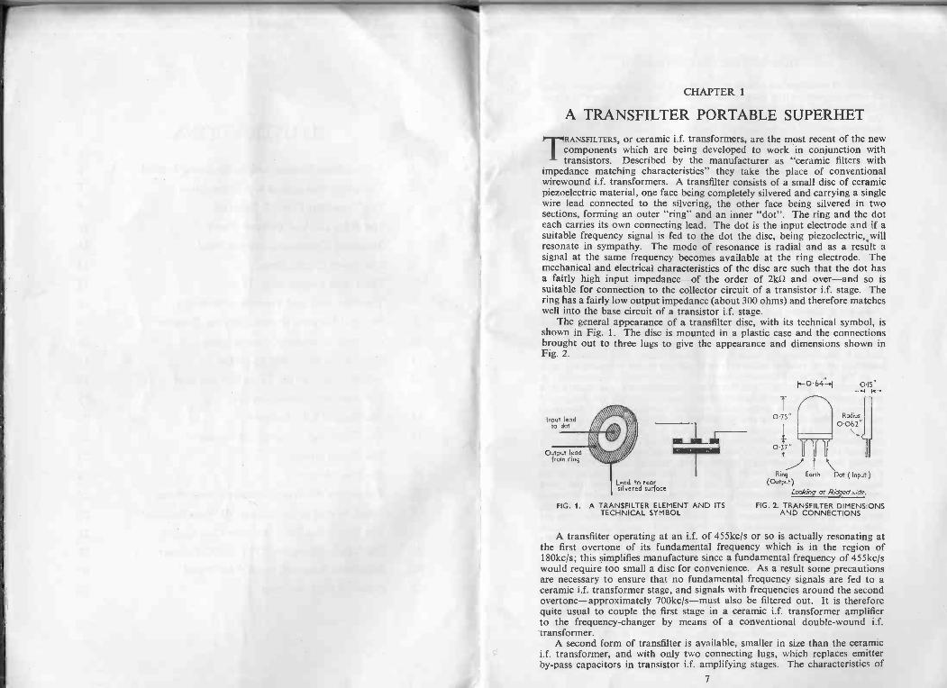
TRANSFELTERS, or ceramic i.f. transformers, are the most recent of the newcomponents which are being developed to work in conjunction withtransistors. Described by the manufacturer as "ceramic filters with
impedance matching characteristics" they take the place of conventionalwirewound i.f. transformers. A transfilter consists of a small disc of ceramicpiezoelectric material, one face being completely silvered and carrying a singlewire lead connected to the silvering, the other face being silvered in twosections, forming an outer "ring" and an inner "dot". The ring and the doteach carries its own connecting lead. The dot is the input electrode and if asuitable frequency signal is fed to the dot the disc, being piezoelectric,.willresonate in sympathy. The mode of resonance is radial and as a result asignal at the same frequency becomes available at the ring electrode. Themechanical and electrical characteristics of the disc are such that the dot hasa fairly high input impedance-of the order of 21d2 and over-and so issuitable for connection to the collector circuit of a transistor i.f. stage. Thering has a fairly low output impedance (about 300 ohms) and therefore matcheswell into the base circuit of a transistor i.f. stage.
The general appearance of a transfilter disc, with its technical symbol, isshown in Fig. 1. The disc is mounted in a plastic case and the connectionsbrought out to three lugs to give the appearance and dimensions shown inFig. 2.
Input leadto dot
Output leadfrom ring
Lead to rearsilvered surface
FIG. 1. A TRANSFILTER ELEMENT AND ITSTECHNICAL SYMBOL
0.75"
0.37"
0.15"--H
Radius
0062"\,
cif
(OutputR)ing Earth Dot (Input)
Looking at Ridgad side.
FIG. 2.. TRANSFILTER DIMENSIONSAND CONNECTIONS
A transfilter operating at an i.f. of 455kc/s or so is actually resonating atthe first overtone of its fundamental frequency which is in the region of180kcis; this simplifies manufacture since a fundamental frequency of 455kc/swould require too small a disc for convenience. As a result some precautionsare necessary to ensure that no fundamental frequency signals are fed to aceramic i.f. transformer stage, and signals with frequencies around the secondovertone-approximately 700kc/s-must also be filtered out. It is thereforequite usual to couple the first stage in a ceramic i.f. transformer amplifierto the frequency -changer by means of a conventional double -wound i.f.transformer.
A second form of transfilter is available, smaller in size than the ceramici.f. transformer, and with only two connecting lugs, which replaces emitterby-pass capacitors in transistor i.f. amplifying stages. The characteristics of
7
8 TRANSISTOR CIRCUITS No. 4
this type of transfilter are such that it presents a very low impedance-about15 ohms or less-at the intermediate frequency and a considerably higherimpedance at all other frequencies, thus further improving the selectivity ofthe i.f. circuit. This extra selectivity is not required in the receiver to bedescribed and only the transformer type filters are used.
Transfilters offer several advantages to the constructor, the first of which is,of course, that they require no tuning or adjustment, the i.f. amplifying stagesalways being in tune. Where a wound transformer is used between thefrequency changer and i.f. amplifier, as in the present circuit, this is simplyadjusted during receiver alignment for best results and can never be so faroff tune as to prevent signals from being heard.
A ceramic i.f. circuit is very stable. High frequency transistors can beemployed in common emitter circuits for good gain without any neutralizationand, further, the receiver is very selective, owing to the transfilter action,enabling stations adjacent on the tuning scale to be separated with theminimum of interference. Finally, transfilters are inexpensive, costing littlemore than ordinary i.f. transformers.
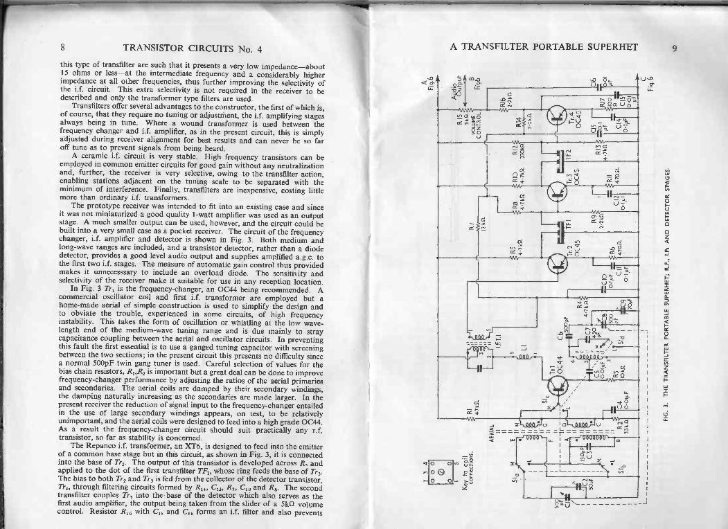
The prototype receiver was intended to fit into an existing case and sinceit was not miniaturized a good quality 1 -watt amplifier was used as an outputstage. A much smaller output can be used, however, and the circuit could bebuilt into a very small case as a pocket receiver. The circuit of the frequencychanger, i.f. amplifier and detector is shown in Fig. 3. Both medium andlong -wave ranges are included, and a transistor detector, rather than a diodedetector, provides a good level audio output and supplies amplified a.g.c. tothe first two i.f. stages. The measure of automatic gain control thus providedmakes it unnecesssary to include an overload diode. The sensitivity andselectivity of the receiver make it suitable for use in any reception location.
In Fig. 3 Tri is the frequency -changer, an 0C44 being recommended. Acommercial oscillator coil and first i.f. transformer are employed but ahome-made aerial of simple construction is used to simplify the design andto obviate the trouble, experienced in some circuits, of high frequencyinstability. This takes the form of oscillation or whistling at the low wave-length end of the medium -wave tuning range and is due mainly to straycapacitance coupling between the aerial and oscillator circuits. In preventingthis fault the first essential is to use a ganged tuning capacitor with screeningbetween the two sections; in the present circuit this presents no difficulty sincea normal 500pF twin gang tuner is used. Careful selection of values for thebias chain resistors, R1,R2 is important but a great deal can be done to improvefrequency -changer performance by adjusting the ratios of the aerial primariesand secondaries. The aerial coils are damped by their secondary windings,the damping naturally increasing as the secondaries are made larger. In thepresent receiver the reduction of signal input to the frequency -changer entailedin the use of large secondary windings appears, on test, to be relativelyunimportant, and the aerial coils were designed to feed into a high grade 0C44.As a result the frequency -changer circuit should suit practically any r.f.transistor, so far as stability is concerned.
The Repanco i.f. transformer, an XT6, is designed to feed into the emitterof a common base stage but in this circuit, as shown in Fig. 3, it is connectedinto the base of Tr2. The output of this transistor is developed across R5 andapplied to the dot of the first transfilter TF1, whose ring feeds the base of Tr3.The bias to both Tr2 and Tr3 is fed from the collector of the detector transistor,Tr4, through filtering circuits formed by R14, C13, R7, C10 and R8. The secondtransfilter couples Tr3 into the base of the detector which also serves as thefirst audio amplifier, the output being taken from the slider of a skn volumecontrol. Resistor R16 with C15 and C16 forms an i.f. filter and also prevents
A TRANSFILTER PORTABLE SUPERHET
II-
O 000O 0
1
r--tn-0 ViaUTi--4F-tv,
3
Mir , ,1141
Umd.
.4.0.100
,.,r..4. st MI ,, ,, a'Pt' 0 v-,0 n-.
I "a tz
, <--f0000000,-'
11
6",
9
10 TRANSISTOR CIRCUITS No. 4
KNe-
cFcL-1.-Al( U..
U
0
E
+L)
r
H
U
-
O
A TRANSFILTER PORTABLE SUPERHET 11
feedback on the long -wave band where the transfilter's fundamental frequencyfalls within the r.f. tuning range.
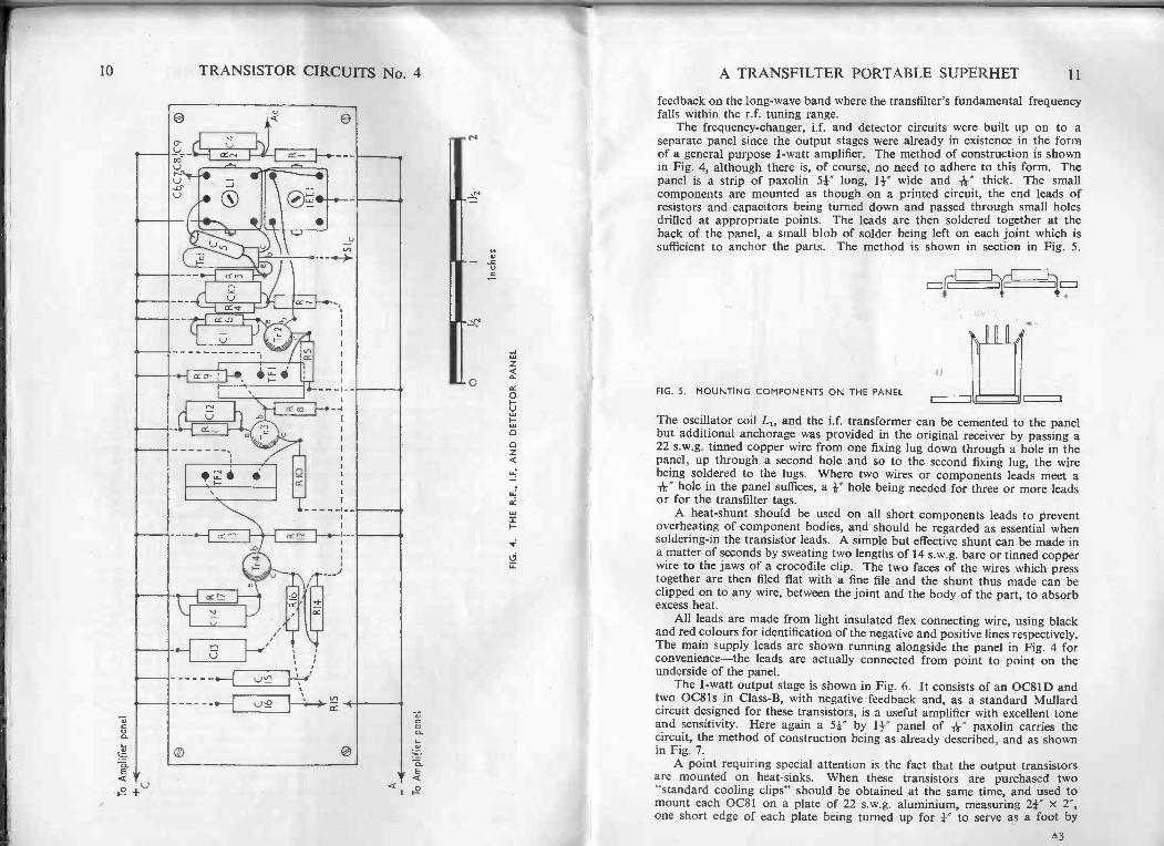
The frequency -changer, i.f. and detector circuits were built up on to aseparate panel since the output stages were already in existence in the formof a general purpose 1 -watt amplifier. The method of construction is shownin Fig. 4, although there is, of course, no need to adhere to this form. Thepanel is a strip of paxolin 51" long, 1F wide and IV thick. The smallcomponents are mounted as though on a printed circuit, the end leads ofresistors and capacitors being turned down and passed through small holesdrilled at appropriate points. The leads are then soldered together at theback of the panel, a small blob of solder being left on each joint which issufficient to anchor the parts. The method is shown in section in Fig. 5.
FIG. 5. MOUNTING COMPONENTS ON THE PANEL
The oscillator coil L1, and the i.f. transformer can be cemented to the panelbut additional anchorage was provided in the original receiver by passing a22 s.w.g. tinned copper wire from one fixing lug down through a hole in thepanel, up through a second hole and so to the second fixing lug, the wirebeing soldered to the lugs. Where two wires or components leads meet aA' hole in the panel suffices, a *" hole being needed for three or more leadsor for the transfilter tags.
A heat -shunt should be used on all short components leads to preventoverheating of component bodies, and should be regarded as essential whensoldering -in the transistor leads. A simple but effective shunt can be made ina matter of seconds by sweating two lengths of 14 s.w.g. bare or tinned copperwire to the jaws of a crocodile clip. The two faces of the wires which presstogether are then filed flat with a fine file and the shunt thus made can beclipped on to any wire, between the joint and the body of the part, to absorbexcess heat.
All leads are made from light insulated flex connecting wire, using blackand red colours for identification of the negative and positive lines respectively.The main supply leads are shown running alongside the panel in Fig. 4 forconvenience-the leads are actually connected from point to point on theunderside of the panel.
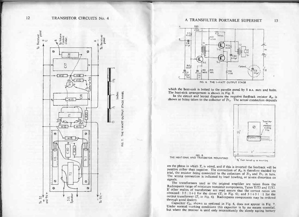
The 1 -watt output stage is shown in Fig. 6. It consists of an OC81D andtwo 0081 s in Class -B, with negative feedback and, as a standard Mullardcircuit designed for these transistors, is a useful amplifier with excellent toneand sensitivity. Here again a 54" by IF panel of -&" paxolin carries thecircuit, the method of construction being as already described, and as shownin Fig. 7.
A point requiring special attention is the fact that the output transistorsare mounted on heat -sinks. When these transistors are purchased two"standard cooling clips" should be obtained at the same time, and used tomount each 0081 on a plate of 22 s.w.g. aluminium, measuring 21- x 2",one short edge of each plate being turned up for 1" to serve as a foot by
A3
12 TRANSISTOR CIRCUITS No. 4
E
o U 0 0cI u aCC
T
9
1=
(.1
V
C
A TRANSFILTER PORTABLE SUPERHET 13
R20
+-C17
R1847k0
C18
ospf
R19121451
1000I5v.w.
-
s
1
100pF;
.....,
R25560k5I.
R222.2kfl.
R212051
b
1T2C20 $p.
4 0.25pF
T r.7
R233911
Optional
R24 i 4C213.351 %
FIG. 6. THE 1 -WATT OUTPUT STAGE
9V
2
which the heat -sink is bolted to the paxolin panel by 8 B.A. nuts and bolts.The heat -sink arrangement is shown in Fig. 8.
In the circuit and layout diagrams the negative feedback resistor R25 isshown as being taken to the collector of Tr6. The actual connection depends
FIG. 8.THE HEAT -SINK AND TRANSISTOR MOUNTING
Transistorin
standardcoolingclip.
1/4 Foot turned up as mounting.
on the phase in which T, is wired, and if this is inverted the feedback will bepositive rather than negative. The connection of R25 is therefore decided bytrial, the resistor being connected to the collectors of Tr6 and Tr., in turn.The wrong connection is indicated by loud howling, or severe distortion onsignals.
The transformers used in the original amplifier are taken from theRadiospares range of miniature transistor components, Types T/T3 and T/T2.If other makes of transformer are used ensure that the correct ratios areobtained: 3.5 : 1+1 for the driver (T, in Fig. 6); and 3.1+3.1 : 1 for theoutput transformer (T in Fig. 6). Radiospares components may be orderedcrthrough good dealers.
Capacitor C21, shown as optional in Fig. 6, does not appear in Fig. 7.Under normal working conditions this capacitor is by no means essential,but where the receiver is used only intermittently the slowly ageing battery
14 TRANSISTOR CIRCUITS No. 4will show the effects of rising internal resistance, the audio tone deterioratinguntil finally the receiver breaks into motor -boating oscillation. Capacitor C21provides a by-pass for a battery in this condition, and so can be said toprolong battery life in so far as it permits ageing batteries to be used for afurther period. If C21 is included the audio amplifier panel could be madeslightly longer to provide a mounting space for the component, or it could bemounted in the case beside the VOLUME CONTROL/ON-OFF switch.
Other types of amplifier and output stage can, of course, be used and,indeed, if a really miniature receiver is to be made of the circuit by theexperimenter the detector, Tr4 of Fig. 3, will drive a personal earpieceadequately with no further amplifying stages. One side of the earpiece istaken to the volume control slider through an 054uF capacitor, the other sideof the earpiece being earthed to the positive battery line as shown in Fig. 9.
VOLUME RIS
CONTROL
RI3
7.5V. Batterywhen earpiece
is used.
NOP
S2 FIG. 9. PERSONAL EARPIECEOUTPUT FROM THE DETECTOR
The dropping and decoupling components, R20 and C17 of Fig. 6 are thenno longer needed, and the receiver can be driven from a 7.5V battery in placeof a 9V supply. Good results have been obtained with an Ardente ER 250earpiece (d.c. resistance 250 ohms, impedance 1k11) and a cheap crystalearpiece has also been used satisfactorily.
A very simple low output power stage which will drive a small loudspeakeris shown in Fig. 10. The performance in no way approaches that of theClass -B 0081 s amplifier of Fig. 6 since the power may be measured in onlytens of milliwatts; but it is sufficient for a personal or bedside receiver. So few
VOLUMECONTROL I 311.
SpeakerTI
9:10P Trans.
Radiospares
1774 9v
FIG. 10. A SIMPLE LOW POWER OUTPUT STAGE
A TRANSFILTER PORTABLE SUPERHET 15
components are used that the circuit could easily be included on the receiverpanel. The stage consists of two transistors coupled in a "super -alpha" pair,the base of the second being connected directly to the emitter of the first, thestage gain of one transistor being multiplied by the gain of the second. Thecircuit is of value in many applications and is particularly useful in relayoperation and similar switching functions.
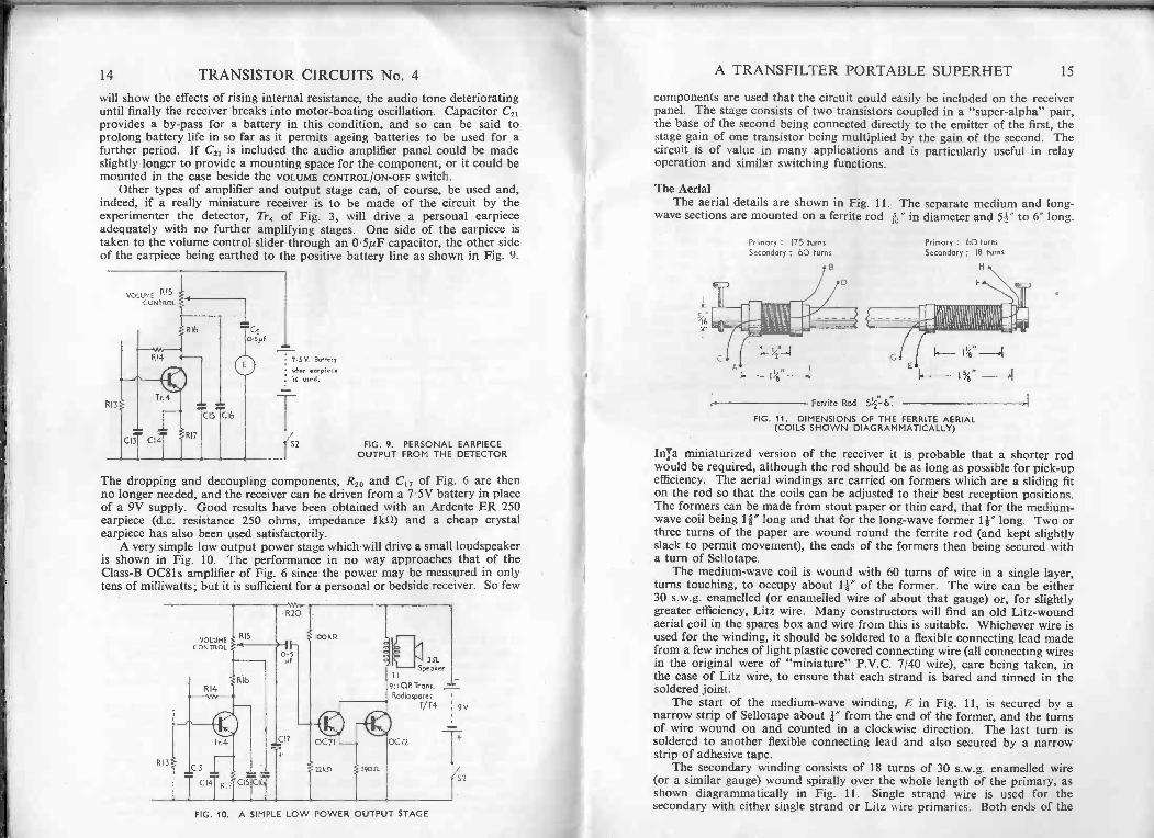
The AerialThe aerial details are shown in Fig. 11. The separate medium and long -
wave sections are mounted on a ferrite rod it" in diameter and 54" to 6' long.
s46
Primary : 175 turns
Secondary : 60 turns
B
Ferrite Rod 51/2'16:
Primary : 60 turns
Secondary: 18 turns
H
Ifigworm11/8"
" -4
FIG. 11. DIMENSIONS OF THE FERRITE AERIAL(COILS SHOWN DIAGRAMMATICALLY)
Inca miniaturized version of the receiver it is probable that a shorter rodwould be required, although the rod should be as long as possible for pick-upefficiency. The aerial windings are carried on formers which are a sliding fiton the rod so that the coils can be adjusted to their best reception positions.The formers can be made from stout paper or thin card, that for the medium -wave coil being 1I" long and that for the long -wave former 1F long. Two orthree turns of the paper are wound round the ferrite rod (and kept slightlyslack to permit movement), the ends of the formers then being secured witha turn of Sellotape.
The medium -wave coil is wound with 60 turns of wire in a single layer,turns touching, to occupy about 1-k" of the former. The wire can be either30 s.w.g. enamelled (or enamelled wire of about that gauge) or, for slightlygreater efficiency, Litz wire. Many constructors will find an old Litz -woundaerial coil in the spares box and wire from this is suitable. Whichever wire isused for the winding, it should be soldered to a flexible connecting lead madefrom a few inches of light plastic covered connecting wire (all connecting wiresin the original were of "miniature" P.V.C. 7/40 wire), care being taken, inthe case of Litz wire, to ensure that each strand is bared and tinned in thesoldered joint.
The start of the medium -wave winding, E in Fig. 11, is secured by anarrow strip of Sellotape about 1" from the end of the former, and the turnsof wire wound on and counted in a clockwise direction. The last turn issoldered to another flexible connecting lead and also secured by a narrowstrip of adhesive tape.
The secondary winding consists of 18 turns of 30 s.w.g. enamelled wire(or a similar gauge) wound spirally over the whole length of the primary, asshown diagrammatically in Fig. 11. Single strand wire is used for thesecondary with either single strand or Litz wire primaries. Both ends of the
16 TRANSISTOR CIRCUITS No. 4
secondary are terminated by flexible connecting wires and secured under turnsof Sellotape. Note that the secondary is wound in the same direction as theprimary.
The long -wave aerial coils occupy a winding space about 4 long on theirformer, and on the original aerial were made between cheeks built up fromseveral turns of narrow strips of Sellotape. Both coils are wound using40 s.w.g. enamelled copper wire (or a similarly small gauge) and as in themedium -wave coils, both are brought out to thin flex leads. The primarywinding consists of 175 turns of wire wound in the same way and in the samedirection as the medium -wave windings, the turns being built up in reasonablyneat layers though meticulous accuracy in laying the turns side -by -side is notat all necessary. The completed winding is covered by a single layer ofadhesive tape and the secondary is then wound over the primary in the samedirection-the secondary consists of 60 turns of the same wire as used for theprimary. The leads to both windings are, of course, secured to the cheeks bystrips of tape.
Note that the long -wave primary coil is trimmed by C3, a 150pF capacitor,permanently connected across the winding, and also that the long -wave coilis short-circuited by Sib when the receiver is switched to the medium -waveband. This prevents the long -wave coil from resonating with its straycapacitances at some frequency within the medium -wave range and so spoilingmedium -wave reception.
As already explained, the secondaries on the aerial coils are large comparedwith normal practice to give adequate damping.
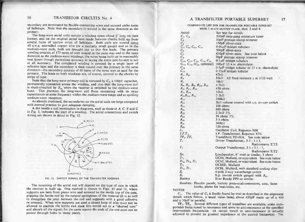
A dot beside a coil termination in diagrams, such as those at A, C, E and Gin Fig. 3, indicates the start of a winding. The aerial connections and switchwiring are shown in detail in Fig. 12.
RI, P.2, C4
CG
E, Kw. Coil.
CI, C2
. Frame of CI,
M.W.
To Base of Tr. I ,
Earth (+ line )
FIG. 12. SWITCH WIRING OF THE TRANSFILTER RECEIVER
The mounting of the aerial rod will depend on the type of case in whichthe receiver is built up. One method is shown in Figs. 11 and 13, wheresupports are bent from piano wire and screwed to the inside top of the case,gripping the ferrite rod by the natural springiness of the material (it is as wellto strengthen the joint between the rod and supports with a good adhesiveor cement). When wire supports are used a closed loop of wire must not beallowed to encircle the ferrite rod since this would act as a "shorted turn"and absorb all the signal; for the same reason the ends of the rod must not bepassed through holes in metal plates.
COMPONENTS LIST FOR THE TRANSFILTER PORTABLE SUPERHETWITH 1 -WATT OUTPUT STAGE, FIGS. 3 and 6
See text for details500pF twin -gang miniature tuner50pF postage stamp trimmer
C3 150pF silver -mica0.01,tiF midget tubulars500pF silver -mica
C7 450pF silver -mica. See note below70pF postage stamp trimmer0.1µF midget tubulars
C17, C19, (C21 optional) 100/4F 15 v.w. electrolytic0.5/4F midget tubular or 15 v.w. electrolytic025/AF midget tubular47k033kn All fixed resistors or 1/10 watt10kil4 -71d2470 ohmsIRO2.2kfl330kLI51d2 volume control with s.p. ON -OFF switch100 ohms
R21 680 ohms2.2k0 5%39 ohms 5%3.3 ohms560kil120 ohmsOscillator Coil, Repanco X08
I.F.T.1 I.F. Transformer, Repanco XT6TF1, TF2 Transfilters TO -01A. See note below
Driver Transformer, 3.5 : 1+1,Radiospares T/T3
T2 Output Transformer, 3-1+3-1 : 1,Radiospares T/T2
Loudspeaker, 6" oval or similar, 3 ohms0C44, Mullard, or equivalent. See note below0C45, Mullard, or equivalent. See note belowOC81D, Mullard0081, Mullard, with standard cooling clips4 -pole 2 -way wavechange switchS.p. oN-oFF switch ganged with R15Ever Ready PP9 or similar
AerialC1, C8C2
C4, C57 C15, C16C6
C9C10, C11, C12, C13, C14
C18C20R1, R18R2R3R4, R5, R8, R10, R13R6, R11, R20.R7, R19R9,R14, R16R12R15R17
A TRANSFILTER PORTABLE SUPERHET 17
R22R23R24R25R26L1
Sp.Tr1Tr2, Tr3, Tr4Tr3Tr6, Tr7S152BatterySundries: Paxolin panels, battery press -stud -connectors, case, three
knobs, plates for heat -sinks, etc.NOTES
C7. The value of C7 is finally found by trial as described in the alignmentdetails which follow, a usual value being about 450pF made up of a 400and a 50pF in parallel.
TF1, TF2. Several different types of transfilter are available, some com-ponents being tuned to resonance and some to anti -resonance at the specifiedintermediate frequencies. (A circuit tuned to anti -resonance is actuallyadjusted to present its greatest impedance at the quoted frequency). The
18 TRANSISTOR CIRCUITS No. 4 A TRANSFILTER PORTABLE SUPERHET 19
transfilters currently available are marketed by the Brush Crystal Companyand their codings are TO-Ol for resonant tuned transfilters and TO -02 foranti -resonant operation. The full codings and frequencies are as follows:
TO -01A 455 ± 2kc/s TO -02A 457 + lkc/sTO -01B 465 + 2kc/s TO -02B 465 ± lkc/sTO -01C 500 ± 2kc/s TO -02C 500 ± 1 kc/sTO -01D 470 ± 2kc/s TO -02D 470 ± 1 kcis
The original receiver was designed round two TO -01A transfilters but toinvestigate the performance if different components were used these werereplaced by TO -02D transfilters-thus both the intermediate frequency andthe basic type of transfilter were altered. After a slight readjustment to thei.f. transformer and the core of the oscillator coil results on listening tests ina poor reception area were just as satisfactory. As a result transfilters of theTO -01A type are specified but the set should operate equally well usingTO -01B or D, or TO -02A, B or D types. The 500kcis units are not recom-mended because this frequency is rather too high to suit the oscillator coiland i.f. transformer. It will, of course, be realized that the two transfiltersmust be of the same type. Transfilters are not yet stocked by all retailersbut they are advertised regularly in technical magazines. At the time ofwriting they cost 8s. 6d. each.
Tr,. An 0C44 is recommended as the frequency -changer but white spotsurplus transistors have been tested in this position with good results. Itmay be necessary to alter the value of R1 to suit other transistors, or to improveresults, but this can be done by trial. If signals are weak bridge R1 with about100k0 to try the effect of more negative bias on the base of the frequency -changer; if an improvement is obtained make a further trial with an 82k0or 68k0 to see if the improvement can be increased. If, on the other hand,the stage is "lively" and breaks into oscillation with the main tuningcapacitor at minimum capacitance, R1 should be increased in value. To saveunsoldering the components the same effect can be obtained by reducing theresistance of R2 which can have a 100kD resistor bridged across it for a trial.If some improvement is obtained, again reduce the value of the bridgingresistor to 82k0 or 68kS2 until the stage operates correctly and is stable.
Tr2, Tr3, Tr4. White spot or blue spot surplus transistors can be used inthese stages with satisfactory results. As a general rule the componentsvalues given will serve for substitute transistors. Red spot transistors havebeen tried in the Tr4 position with good results. At the time of writing it ispossible to purchase, at greatly reduced prices, "packages" of transistors con-taining 1 0C44, 2 OC45s, 1 OC81D and a pair of 0081s, intended for moreconventional receivers. Such a package can, of course, be used in the existingcircuit with the addition of a further 0C45 or substitute.
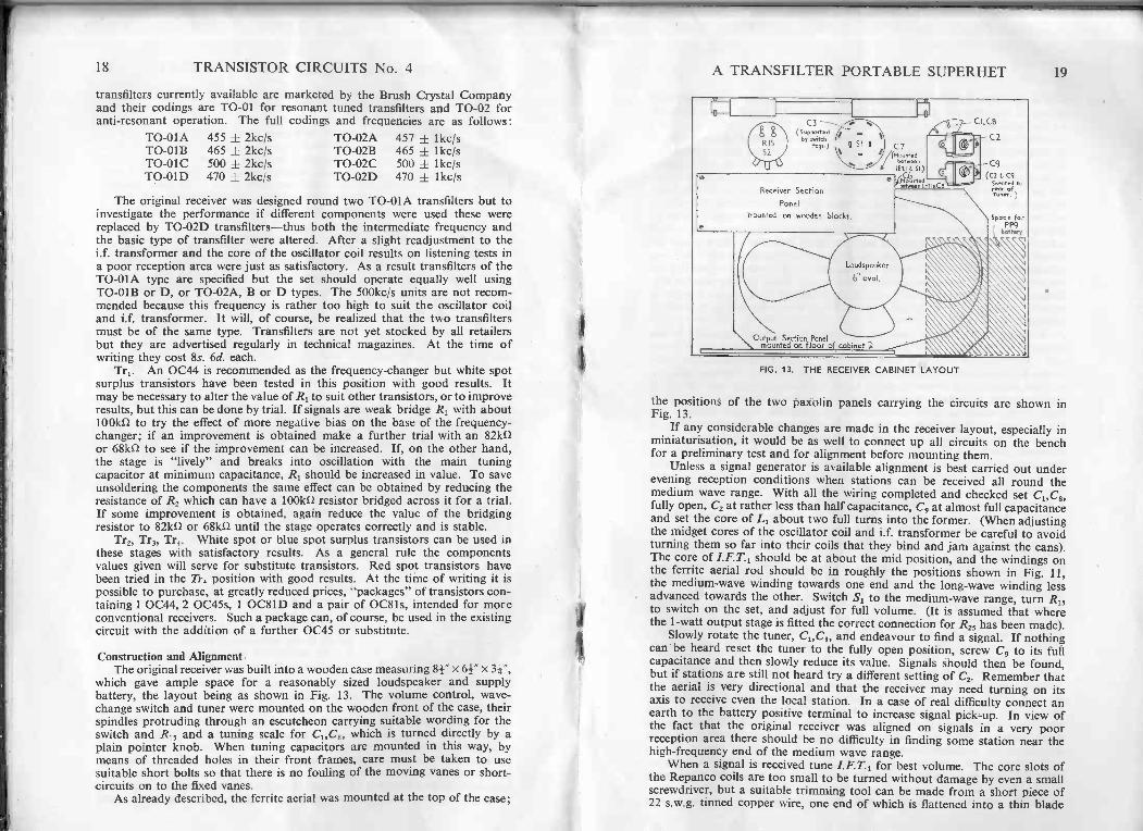
Construction and AlignmentThe original receiver was built into a wooden case measuring 84" x 64" x 3r,
which gave ample space for a reasonably sized loudspeaker and supplybattery, the layout being as shown in Fig. 13. The volume control, wave -change switch and tuner were mounted on the wooden front of the case, theirspindles protruding through an escutcheon carrying suitable wording for theswitch and R15 and a tuning scale for C1,C8, which is turned directly by aplain pointer knob. When tuning capacitors are mounted in this way, bymeans of threaded holes in their front frames, care must be taken to usesuitable short bolts so that there is no fouling of the moving vanes or short-circuits on to the fixed vanes.
As already described, the ferrite aerial was mounted at the top of the case;
Receiver Section
Panel
mounted on wooden blocks.
Loudspeaker
6" oval.
FIG. 13. THE RECEIVER CABINET LAYOUT
the positions of the two paxolin panels carrying the circuits are shown inFig. 13.
If any considerable changes are made in the receiver layout, especially inminiaturisation, it would be as well to connect up all circuits on the benchfor a preliminary test and for alignment before mounting them.
Unless a signal generator is available alignment is best carried out underevening reception conditions when stations can be received all round themedium wave range. With all the wiring completed and checked set C1,C3,fully open, C2 at rather less than half capacitance, C9 at almost full capacitanceand set the core of L1 about two full turns into the former. (When adjustingthe midget cores of the oscillator coil and i.f. transformer be careful to avoidturning them so far into their coils that they bind and jam against the cans).The core of I.F.T.1 should be at about the mid position, and the windings onthe ferrite aerial rod should be in roughly the positions shown in Fig. 11,the medium -wave winding towards one end and the long -wave winding lessadvanced towards the other. Switch S1 to the medium -wave range, turn R15to switch on the set, and adjust for full volume. (It is assumed that wherethe 1 -watt output stage is fitted the correct connection for R25 has been made).
Slowly rotate the tuner, C1,C8, and endeavour to find a signal. If nothingcan be heard reset the tuner to the fully open position, screw C9 to its fullcapacitance and then slowly reduce its value. Signals should then be found,but if stations are still not heard try a different setting of C2. Remember thatthe aerial is very directional and that the receiver may need turning on itsaxis to receive even the local station. In a case of real difficulty connect anearth to the battery positive terminal to increase signal pick-up. In view ofthe fact that the original receiver was aligned on signals in a very poorreception area there should be no difficulty in finding some station near thehigh -frequency end of the medium wave range.
When a signal is received tune I.F.T.1 for best volume. The core slots ofthe Repanco coils are too small to be turned without damage by even a smallscrewdriver, but a suitable trimming tool can be made from a short piece of22 s.w.g. tinned copper wire, one end of which is flattened into a thin blade
20 TRANSISTOR CIRCUITS No. 4
with a few taps from a light hammer. The wire can then be inserted andcemented into an orange stick and the blade used to trim the cores withno fear of harm.
Now turn the tuner over its range. Probably a number of stations will beheard as the vanes start to mesh, but signals will rapidly die away into silenceas the capacitance is increased. Make a slight alteration to the core settingof L1, turning the core either in or out by a half -turn or so, and again rotatethe main tuner from minimum capacitance towards maximum. If the coreadjustment of L1 was made in the correct direction a greater number of stationswill be heard before the signals die away; if the adjustment to the core of L1was in the wrong direction there will, of course, be fewer signals heard. Makea further correction to L1 and aim at a setting of the core where stations areheard all the way round the tuning range of the variable capacitor. As theseadjustments progress, check the medium -wave aerial winding for position onthe ferrite rod by leaving the main tuner set on a station towards the lowfrequency end of the tuning range and moving the medium -wave windingto and fro along the rod. A point will be found where the station is heard atbest volume.
At this point it will be necessary to adjust C9 because improving resultsat the low -frequency end of the band will affect results at the high -frequencyend. Turn C9, with the main tuner fully open, until stations are again heardat the high -frequency end of the range, and then adjust C2 for best volume.
The actual range over which the tuner is operating must now be foundand corrected. The final range is of the order of 205 to 550 metres and if theLight Programme on 247 metres can be identified the correct tuning pointfor this signal is with the tuner vanes about 22° in mesh from the fully -openpoint. A very convenient way of setting the high -frequency end of the range,however, is to adjust C9 so that Luxembourg is tuned in with C1,C8, practicallyright open. When this setting of C9 has been found by trial, adjust C2 for bestvolume, then tune to a station at the other end of the range and again correctthe position of the medium -wave aerial winding on the rod. Tune back to theLight Programme on 247 metres and make a further correction to C2 for bestvolume. Signals should now be heard all round the medium -wave band;if there appear to be any dead spots in the centre of the tuning range it willbe necessary to make a further adjustment to L1 and then to C9, C2, and theaerial winding.
If a high gain 0C44 has been used as the frequency -changer someinstability may appear at the high -frequency end of the tuning range as C9 isreduced in value to make the Light Programme, or Luxembourg, fall on thecorrect tuning point. Check the setting of C2, then slightly reduce the biason the transistor in the manner already described, shunting R2 by trial with100k1/ or less until the stage is stabilized, and works correctly. Alternatively,add a further one or two turns to the secondary winding G -H on the aerialcoil.
Switch S1 for long -wave reception, and set the main tuner to the centre ofits tuning range. If C, is suited to the adjustments already made to the coreof L1 the Light Programme will be heard at good strength but it is possiblethat C, will need some alteration. One method of finding the correct valueof C, is to connect a variable padder capacitor in place of the fixed capaci-tance, using a 750pF max. component, but if one or two 50pF silver micacapacitors are available these may be connected in parallel one at a timewith a fixed 400pF capacitor to give 450, 500, 550pF, etc. Swing C1,C8, aftereach alteration to C7 and also vary the position of the long -wave winding onthe aerial rod until the Light Programme is received. If reception is poorcheck the value of C3 by adding 50pF in parallel to the existing capacitor.
A TRANSFILTER PORTABLE SUPERHET 21
If results are worse change the 150pF component for (say) 100pF; if addingcapacitance improves results try a further increase in capacitance. With thecorrect values for C3 and C and the aerial coil correctly positioned on theferrite rod, good results should be had not only from the Light Programmeon 1,500 metres, but also from the long -wave Luxembourg and Frenchtransmitters.
After altering the position of the long -wave aerial coil, switch back tothe medium -wave band and ascertain whether the medium-wave aerial coilsetting has been affected, and correct it if necessary. When the receiver isaligned throughout, cement the aerial windings in place on the rod with adab of Durofix. The cores of L1 and I.F.T.1 can be sealed by dropping ascrap of wax on the top of each core and melting it with a hot wire.
When the 1 -watt output stage is fitted to the receiver a final check can becarried out on the audio tone. Under ordinary reception conditions thereceiver has very little background hiss (unlike some transistor circuits) andwhen the set is tuned off signals, with the volume control fully advanted,there should be practically no sound at all from the loudspeaker. If hiss isheard when this test is made temporarily disconnect C18 from the slider of R13.A reduction in hiss indicates that the noise is arising in the receiver section,probably in Tr4. If, on the other hand, the hiss level is unchanged, the noiseis due to the amplifier.
To reduce noise in the Tr4 stage, assuming that the transistor itself is ingood order, remove R12, 330k0, and replace it by a 470k0 resistor. If hissarises in the audio stages check R18 and try an increase in value; also checkR22. A 5 per cent tolerance resistor is specified here and therefore the resistorwill be reasonably correct; if Tr6 and Tr7 have high betas, however, it may benecessary to increase R22 by trial for best results.
As a general rule noise will not be troublesome with this circuit and aftertesting for hiss it should be possible to go straight on to a tone test. To makethis trial without test equipment, tune the receiver to a strong signal-theLight Programme on long waves, for example-and check the tone on musicwith the volume control fully up, then turned down to the lowest volumewhich can clearly be heard. At high volume the tone should be excellent,and should be maintained as the volume is reduced. At low levels, if thereis slight cracking or distortion suspect the bias on Tr6 and Tr7, and shuntR22 with about 10k0 to see if the tone improves. This form of distortion atlow levels in a Class -B stage indicates that the bias is slightly low, givingcross -over distortion; as one transistor cuts -off, the other is not quite con-ducting, and a slight rise in bias usually cures the trouble. In one amplifierconstructed by the author R22 had to be shunted by 4.7k0.
A final test also concerns distortion on low volume but in this case thereceiver is tuned to the, weakest signal which can be heard, the volume controlbeing turned fully on. If cracking or distortion is heard on a weak signalit can probably be improved by increasing the bias on Tr4 by shunting R12 by1 megohm or 560k0 by trial. On the other hand, if R12 has been increasedto reduce hiss a compromise must, of course, be made between noise and tone.
Battery life in this receiver depends to a great extent on the volumerequired. At full output peak currents of 250mA are drawn, but for averagelistening a typical battery current is 100mA on peaks, falling to a steady15mA or less with no signal.
A
CHAPTER 2A SIMPLE ALL -WAVE T.R.F. RECEIVER 23
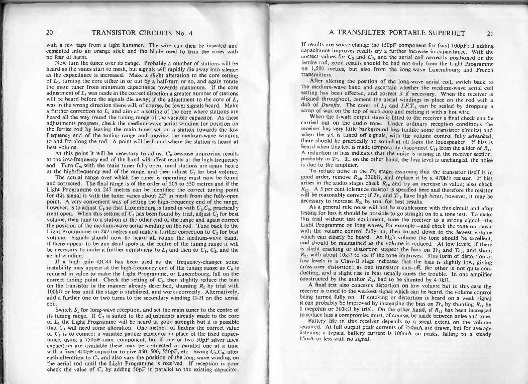
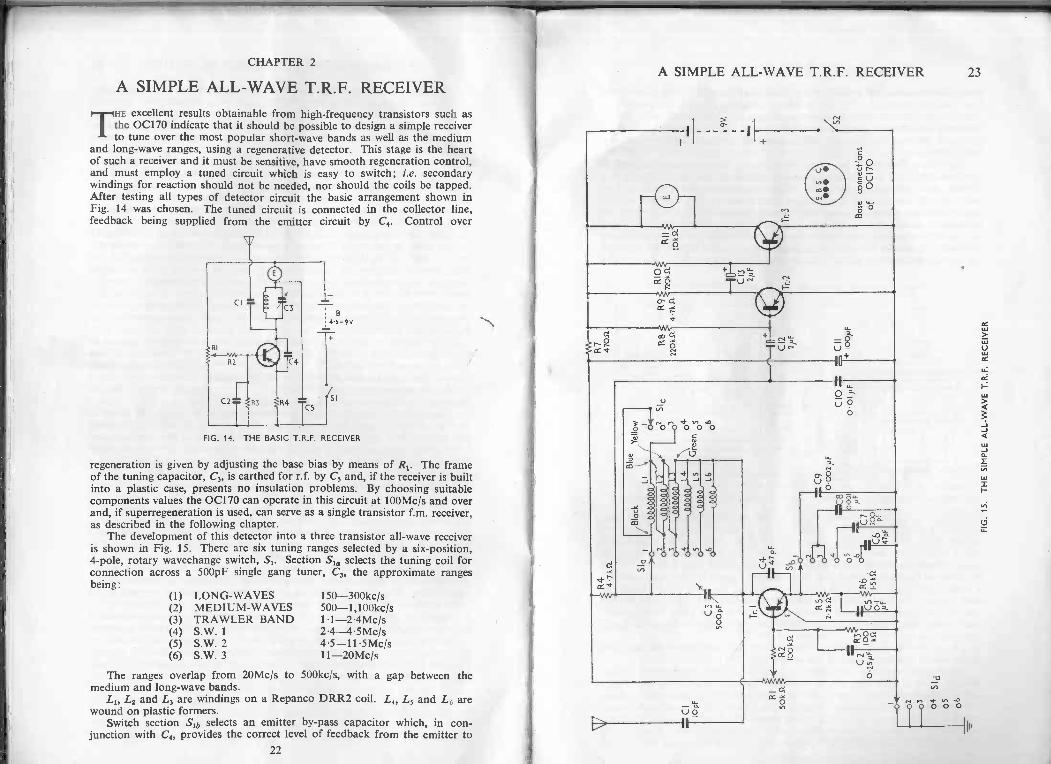
A SIMPLE ALL -WAVE T.R.F. RECEIVERTHE excellent results obtainable from high -frequency transistors such asthe 0C170 indicate that it should be possible to design a simple receiverto tune over the most popular short-wave bands as well as the medium
and long -wave ranges, using a regenerative detector. This stage is the heartof such a receiver and it must be sensitive, have smooth regeneration control,and must employ a tuned circuit which is easy to switch; i.e. secondarywindings for reaction should not be needed, nor should the coils be tapped.After testing all types of detector circuit the basic arrangement shown inFig. 14 was chosen. The tuned circuit is connected in the collector line,feedback being supplied from the emitter circuit by C4. Control over
(-4 <1-0 0 0FIG. 14. THE BASIC T.R.F. RECEIVER
regeneration is given by adjusting the base bias by means of R1. The frameof the tuning capacitor, C3, is earthed for r.f. by C5 and, if the receiver is builtinto a plastic case, presents no insulation problems. By choosing suitablecomponents values the 0C170 can operate in this circuit at 100Mc/s and overand, if superregeneration is used, can serve as a single transistor f.m. receiver,as described in the following chapter.
The development of this detector into a three transistor all -wave receiveris shown in Fig. 15. There are six tuning ranges selected by a six -position,4 -pole, rotary wavechange switch, Si. Section Su, selects the tuning coil forconnection across a 500pF single gang tuner, C3, the approximate rangesbeing:
(1)(2)(3)(4)(5)(6)
LONG -WAVESMEDIUM -WAVESTRAWLER BANDS.W. 1S.W. 2S.W. 3
150-300kc/s500-1,100kcis1.1-2.4Mc/s2.4-4.5Mc/s4.5-11.5Mc/s11-20Mc/s
The ranges overlap from 20Mc/s to 500kc/s, with a gap between themedium and long -wave bands.
L1, Lz and L3 are windings on a Repanco DRR2 coil. Li, L5 and L6 arewound on plastic formers.
Switch section Sib selects an emitter by-pass capacitor which, in con-junction with C4, provides the correct level of feedback from the emitter to
v0cc
0
°O
00
-o-o-10+
H LL
0U o
O
a- c'5
_Ho ,0 oLL
goy
VA
Iq 0 0 0
22
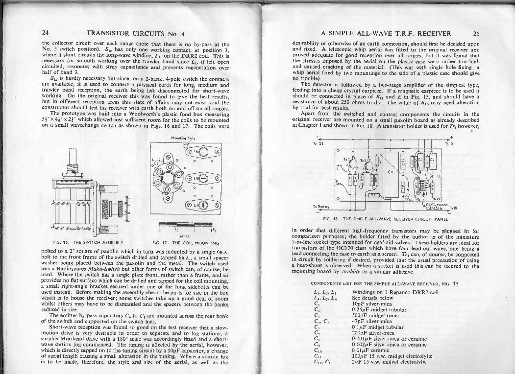
24 TRANSISTOR CIRCUITS No. 4the collector circuit over each range (note that there is no by-pass at theNo. 5 switch position). SI, has only one working contact, at position 3,where it short circuits the long -wave winding, LI, on the DRR2 coil. This isnecessary for smooth working over the trawler band since LI, if left opencircuited, resonates with stray capacitance and prevents regeneration overhalf of band 3.
Sld is hardly necessary but since, on a 2 -bank, 4 -pole switch the contactsare available, it is used to connect a physical earth for long, medium andtrawler band reception, the earth being left disconnected for short-waveworking. On the original receiver this was found to give the best results,but in different reception areas this state of affairs may not exist, and theconstructor should test his receiver with earth both on and off on all ranges.
The prototype was built into a Woolworth's plastic food box measuringx 4r x 24 which allowed just sufficient room for the coils to be mounted
on a small wavechange switch as shown in Figs. 16 and 17. The coils were
FIG. 16. THE SWITCH ASSEMBLY
Mounting hole
Q2) L60
O Lse mf
0Inches
FIG. 17. THE COIL MOUNTING
1y2
bolted to a r square of paxolin which in turn was mdunted by a single 6B.A.bolt to the front frame of the switch drilled and tapped 6B.A., a small spacerwasher being placed between the paxolin and the metal. The switch usedwas a Radiospares Maka-Switch but other forms of switch can, of course, beused. Where the switch has a single plate front, rather than a frame, and soprovides no flat surface which can be drilled and tapped for the coil mounting,a small right-angle bracket secured under one of the long sidebolts can beused instead. Before making the assembly check the parts for size in the boxwhich is to house the receiver; some switches take up a good deal of roomwhilst others may have to be dismantled and the spacers between the banksreduced in size.
The emitter by-pass capacitors C6 to C9 are mounted across the rear bankof the switch and supported on the switch lugs.
Short-wave reception was found so good on the test receiver that a slow-motion drive is very desirable in order to separate and to log stations; asurplus Muirhead drive with a 180° scale was accordingly fitted and a short-wave station log commenced. The tuning is affected by the aerial, however,which is directly tapped on to the tuning circuit by a 10pF capacitor, a changeof aerial length causing a small alteration in the tuning. Where a station logis to be made, therefore, the style and size of the aerial, as well as the
A SIMPLE ALL -WAVE T.R.F. RECEIVER 25
desirability or otherwise of an earth connection, should first be decided uponand fixed. A telescopic whip aerial was fitted to the original receiver andproved adequate for good reception over all ranges, but it was found thatthe stresses imposed by the aerial on the plastic case were rather too highand caused cracking of the material. (This was with single hole fixing; awhip aerial fixed by two mountings to the side of a plastic case should giveno trouble).
The detector is followed by a two -stage amplifier of the simplest type,feeding into a cheap crystal earpiece. If a magnetic earpiece is to be used itshould be connected in place of R11 and E in Fig. 15, and should have aresistance of about 250 ohms to d.c. The value of R1,3 may need alterationby trial for best results.
Apart from the switched and control components the circuits in theoriginal receiver are mounted on a small paxolin board as already describedin Chapter 1 and shown in Fig. 18. A transistor holder is used for Tri however,
To S2
To Battery
O
RI
11
)To RI
CI.C3,srksoRLIL4LS16. To RI
FIG. 18. THE SIMPLE ALL -WAVE RECEIVER CIRCUIT PANEL
in order that different high -frequency transistors may be plugged in forcomparison purposes; the holder fitted by the author is of the miniature5 -in -line socket type intended for deaf -aid valves. These holders are ideal fortransistors of the 0C170 class which have four lead -out wires, one being alead connecting the case to earth as a screen. Tri can, of course, be connectedin circuit by soldering if desired, provided that the usual precaution of usinga heat -shunt is observed. When a socket is used this can be secured to themounting board by Araldite or a similar adhesive.
COMPONENTS LIST FOR THE SIMPLE ALL -WAVE RECEIVER, FIG. 15
L1, L2, L3 Windings on 1 Repanco DRR2 coilL4, L5, L6 See details belowCI 10pF silver -micaC2 0.25µF midget tubularC3 500pF midget tunerC4, C6 47pF silver -micaC3 o'lpF midget tubularC7 200pF silver -micaC8 0.001µF silver -mica or ceramicC9 0.002µF silver -mica or ceramic
0.01µF ceramic100/AF 15 v.w. midget electrolytic2pF 15 v.w. midget electrolytic
C10CuC12, C13
26 TRANSISTOR CIRCUITS No. 4
R, 50k0 volume control with s.p. ox-oFF switchR2, R3 100kfl. All fixed resistors i or 1/10 wattR4, R9 4.7kf/R9 2.2kDR6 1.5knR, 470 ohmsR8, RIO 220kt1B11E Crystal earpieceTr, 0C170, MullardTr,, Tr3 0071, Mullard, or Red Spot, etc.
cl d 4 -pole 6 -way rotary wavechange switchS2 S.P. ON-OFF switch ganged with BIBattery Ever Ready PP3, or similarSundries: Plastic or other insulating case, paxolin panel,
battery press -stud -connectors, coil formers andcores (see below), slow-motion drive, 2 knobs,etc.
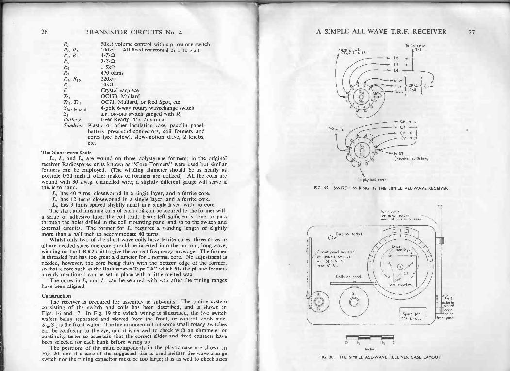
The Short-wave CoilsL4, L5 and L6 are wound on three polystyrene formers; in the original
receiver Radiospares units known as "Core Formers" were used but similarformers can be employed. (The winding diameter should be as nearly aspossible 0.31 inch if other makes of formers are utilized). All the coils arewound with 30 s.w.g. enamelled wire; a slightly different gauge will serve ifthis is to hand.
L4 has 40 turns, closewound in a single layer, and a ferrite core.L5 has 12 turns closewound in a single layer, and a ferrite core.L6 has 9 turns spaced slightly apart in a single layer, with no core.
The start and finishing turn of each coil can be secured to the former witha scrap of adhesive tape, the coil leads being left sufficiently long to passthrough the holes drilled in the coil mounting panel and so to the switch andexternal circuits. The former for L4 requires a winding length of slightlymore than a half inch to accommodate 40 turns.
Whilst only two of the short-wave coils have ferrite cores, three cores inall are needed since one core should be inserted into the bottom, long -wave,winding on the DRR2 coil to give the correct frequency coverage. The formeris threaded but has too great a diameter for a normal core. No adjustment isneeded, however, the core being flush with the bottom edge of the former,so that a core such as the Radiospares Type "A" which fits the plastic formersalready mentioned can be set in place with a little melted wax.
The cores in L4 and L5 can be secured with wax after the tuning rangeshave been aligned.
ConstructionThe receiver is prepared for assembly in sub -units. The tuning system
consisting of the switch and coils has been described, and is shown inFigs. 16 and 17. In Fig. 19 the switch wiring is illustrated, the two switchwafers being separated and viewed from the front, or control knob side.Sia,Si, is the front wafer. The lug arrangement on some small rotary switchescan be confusing to the eye, and it is as well to check with an ohmmeter orcontinuity tester to ascertain that the correct slider and fixed contacts havebeen selected for each bank before wiring up.
The positions of the main components in the plastic case are shown inFig. 20, and if a case of the suggested size is used neither the wave -changeswitch nor the tuning capacitor must be too large; it is as well to check sizes
A SIMPLE ALL -WAVE T.R.F. RECEIVER
Frame of C3,CO,C12, G R4.
Emitter Tr.l
To physical earth.
To Collector,Tr I
L6
L 5
L4
Yellow '1
Blue
Block
C6
C7
CB
C9
DRR2Coil
Green
To S2
(Receiver earth line)
FIG. 19. SWITCH WIRING IN THE SIMPLE ALL -WAVE RECEIVER
Whip oeriolor aerial socketmounted on side of cose
Circuit panel mountedon spacers on sidewall of case torear of RI.
Earthsociet to
rear ofaerialor on
front panel
FIG. 20. THE SIMPLE ALL -WAVE RECEIVER CASE LAYOUT
27
28 TRANSISTOR CIRCUITS No. 4
and offer up the parts before any assembly or drilling takes place. Largecomponents can of course be used if a suitable housing is to hand.
In the original receiver the bottom of the plastic box formed the frontpanel. Drilling must be carried out very carefully with the material wellsupported on a flat surface, otherwise the plastic will crack as the bit breaksthrough.
The majority of small tuners are mounted by means of three holes in thefront frame on a 1 -inch circle, tapped 4B.A. and care must be taken that themounting bolts do not protrude through the frame and so distort or shortcircuit the capacitor plates. It is convenient to space the tuner behind thefront panel by stacks of washers over the bolts so that just sufficient spindleprotrudes to engage the slow-motion drive where this is used. This alsopermits a Muirhead drive to be bolted to the front panel by 8 or 9B.A. nutsand bolts.
Several mounting positions are available for the components board whichmeasures only 3 x 11 inches; in the original receiver it was bolted to one sideof the case to the rear, and clear of, R1 as shown in Fig. 20. The aerial andearth sockets, or whip aerial and earth socket, can be secured along one sideof the case, whilst the earpiece socket is mounted on the front panel. Plentyof space is left for a small 9V battery, which can be housed in a small com-partment made from balsa wood cemented to the case, or in some similarmanner, to prevent the battery from moving about when the receiver is carried.
With the wiring completed the receiver can be tested. If a whip aerial isnot fitted use about six feet of insulated wire as a "throw -out" aerial for firsttrials. Turn the wavechange switch to RANGE 1 for long -wave reception,switch on with R1,S2 and turn up the control until the detector just breaksinto regeneration or oscillation, then back off the control so that the receiveris in a sensitive condition but not actually oscillating. Turn the tuning control;the long -wave Light Programme should be found without difficulty as wellas two or three other stations depending on the reception location.
Switch to RANGE 2 for medium -wave reception and again adjust R1 so thatthe receiver is just not oscillating. The local station should be heard as shouldseveral other signals; under evening conditions the dial should be full ofstations.
Check the trawler band for regeneration over the whole tuning range.At frequencies above 1.5Mc/s or so it will be necessary to allow the detectorto oscillate in order to hear the heterodyne whistle on weak signals, backingoff R1 when a station has been found. On RANGES 4, 5 and 6 the same methodof tuning can be used, backing off the reaction as soon as the required stationis received. It is important not to allow the receiver to oscillate in such a waythat it might cause interference in neighbouring sets since this is offensiveboth in fact and in law.
The overlap between the tuning ranges can be adjusted by setting theferrite cores in L4 and L5. Ideally this requires a signal generator, but onemethod is to identify a station at the high -frequency end of the trawler band,then to tune in the same station at the low -frequency end of range 4, settingthe core in L4 so that the tuner is almost wholly closed. The same method isemployed to align L, with L4; L6 should overlap L5 automatically.
CHAPTER 3
TRANSISTORS AT V.H.F.
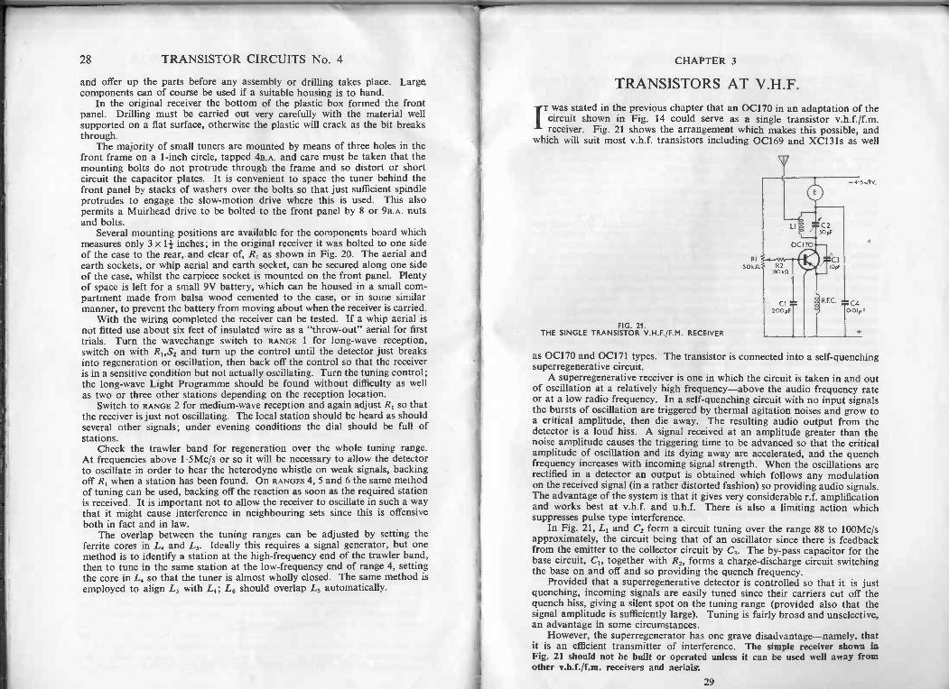
T was stated in the previous chapter that an 0C170 in an adaptation of the
I circuit shown in Fig. 14 could serve as a single transistor v.h.f./f.m.receiver. Fig. 21 shows the arrangement which makes this possible, and
which will suit most v.h.f. transistors including 0C169 and XC131s as well
RI
50 k
FIG. 21.THE SINGLE TRANSISTOR V.H.F./F.M. RECEIVER
as 0C170 and 0C171 types. The transistor is connected into a self -quenchingsuperregenerative circuit.
A superregenerative receiver is one in which the circuit is taken in and outof oscillation at a relatively high frequency-above the audio frequency rateor at a low radio frequency. In a self -quenching circuit with no input signalsthe bursts of oscillation are triggered by thermal agitation noises and grow toa critical amplitude, then die away. The resulting audio output from thedetector is a loud hiss. A signal received at an amplitude greater than thenoise amplitude causes the triggering time to be advanced so that the criticalamplitude of oscillation and its dying away are accelerated, and the quenchfrequency increases with incoming signal strength. When the oscillations arerectified in a detector an output is obtained which follows any modulationon the received signal (in a rather distorted fashion) so providing audio signals.The advantage of the system is that it gives very considerable r.f. amplificationand works best at v.h.f. and u.h.f. There is also a limiting action whichsuppresses pulse type interference.
In Fig. 21, L1 and C2 form a circuit tuning over the range 88 to 100Mc/sapproximately, the circuit being that of an oscillator since there is feedbackfrom the emitter to the collector circuit by C,. The by-pass capacitor for thebase circuit, C1, together with R2, forms a charge -discharge circuit switchingthe base on and off and so providing the quench frequency.
Provided that a superregenerative detector is controlled so that it is justquenching, incoming signals are easily tuned since their carriers cut off thequench hiss, giving a silent spot on the tuning range (provided also that thesignal amplitude is sufficiently large). Tuning is fairly broad and unselective,an advantage in some circumstances.
However, the superregenerator has one grave disadvantage-namely, thatit is an efficient transmitter of interference. The simple receiver shown inFig. 21 should not be built or operated unless it can be used well away fromother v.h.f./f.m. receivers and aerials.
29
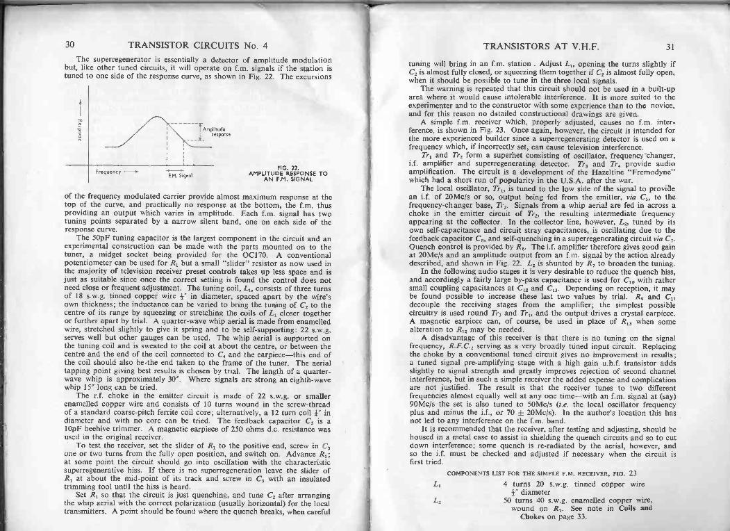
30 TRANSISTOR CIRCUITS No. 4The superregenerator is essentially a detector of amplitude modulation
but, like other tuned circuits, it will operate on f.m. signals if the station istuned to one side of the response curve, as shown in Fig. 22. The excursions
TAmplituda
response
FrequencyF.M. Signal
FIG. 22.AMPLITUDE RESPONSE TO
AN F.M. SIGNAL
of the frequency modulated carrier provide almost maximum response at thetop of the curve, and practically no response at the bottom, the f.m. thusproviding an output which varies in amplitude. Each f.m. signal has twotuning points separated by a narrow silent band, one on each side of theresponse curve.
The 50pF tuning capacitor is the largest component in the circuit and anexperimental construction can be made with the parts mounted on to thetuner, a midget socket being provided for the 0C170. A conventionalpotentiometer can be used for RI but a small "slider" resistor as now used inthe majority of television receiver preset controls takes up less space and isjust as suitable since once the correct setting is found the control does notneed close or frequent adjustment. The tuning coil, L1, consists of three turnsof 18 s.w.g. tinned coppei wire I" in diameter, spaced apart by the wire'sown thickness; the inductance can be varied to bring the tuning of C2 to thecentre of its range by squeezing or stretching the coils of L1 closer togetheror further apart by trial. A quarter -wave whip aerial is made from enamelledwire, stretched slightly to give it spring and to be self-supporting: 22 s.w.g.serves well but other gauges can be used. The whip aerial is supported onthe tuning coil and is sweated to the coil at about the centre, or between thecentre and the end of the coil connected to C4 and the earpiece-this end ofthe coil should also be -the end taken to the frame of the tuner. The aerialtapping point giving best results is chosen by trial. The length of a quarter -wave whip is approximately 30". Where signals are strong an eighth -wavewhip 15" long can be tried.
The r.f. choke in the emitter circuit is made of 22 s.w.g. or smallerenamelled copper wire and consists of 10 turns wound in the screw -threadof a standard coarse -pitch ferrite coil core; alternatively, a 12 turn coil i" indiameter and with no core can be tried. The feedback capacitor C3 is a10pF beehive trimmer. A magnetic earpiece of 250 ohms d.c. resistance wasused in the original receiver.
To test the receiver, set the slider of R1 to the positive end, screw in C3one or two turns from the fully open position, and switch on. Advance RI;at some point the circuit should go into oscillation with the characteristicsuperregenerative hiss. If there is no superregeneration leave the slider ofR1 at about the mid -point of its track and screw in C3 with an insulatedtrimming tool until the hiss is heard.
Set R1 so that the circuit is just quenching, and tune C2 after arrangingthe whip aerial with the correct polarization (usually horizontal) for the localtransmitters. A point should be found where the quench breaks, when careful
TRANSISTORS AT V.H.F. 31
tuning will bring in an f.m. station . Adjust L1, opening the turns slightly ifC2 is almost fully closed, or squeezing them together if C2 is almost fully open,when it should be possible to tune in the three local signals.
The warning is repeated that this circuit should not be used in a built-uparea where it would cause intolerable interference. It is more suited to theexperimenter and to the constructor with some experience than to the novice,and for this reason no detailed constructional drawings are given.
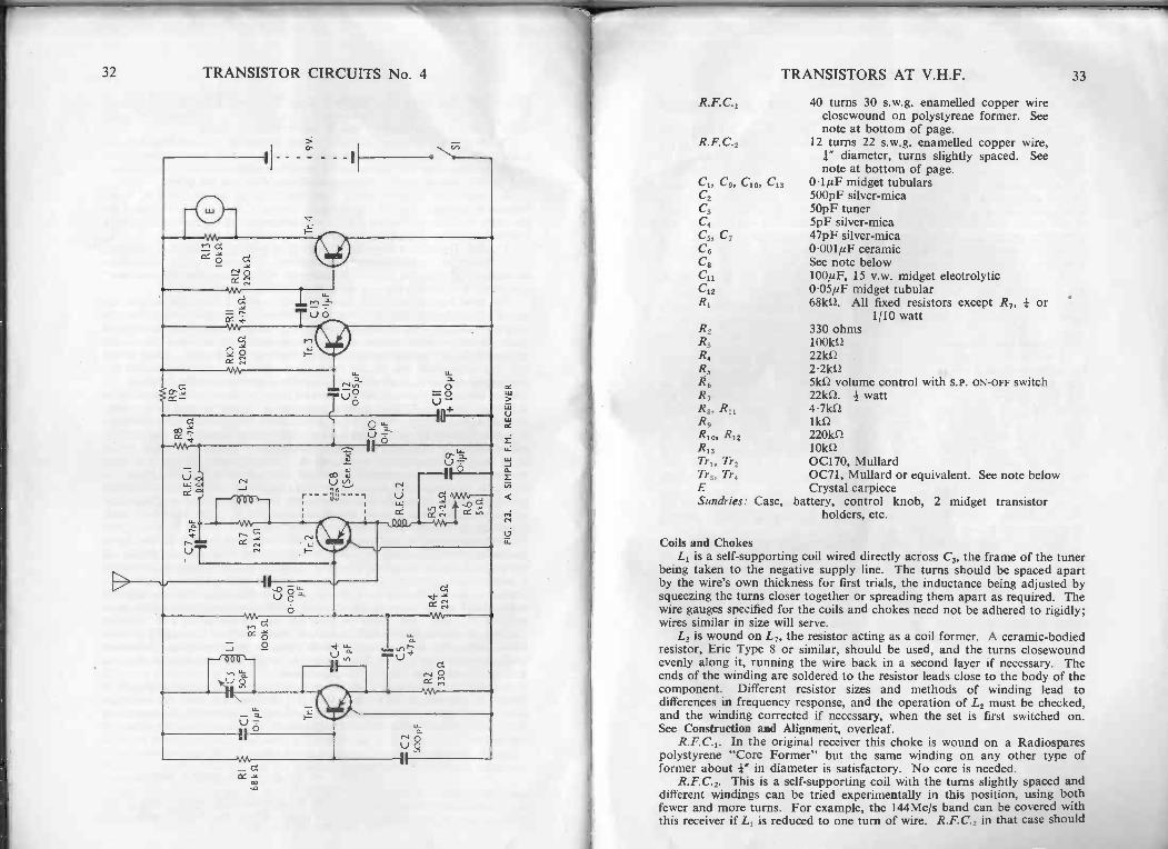
A simple f.m. receiver which, properly adjusted, causes no f.m. inter-ference, is shown in Fig. 23. Once again, however, the circuit is intended forthe more experienced builder since a superregenerating detector is used on afrequency which, if incorrectly set, can cause television interference.
Tr1 and Tr2 form a superhet consisting of oscillator, frequency changer,i.f. amplifier and superregenerating detector. Tr3 and Tr4 provide audioamplification. The circuit is a development of the Hazeltine "Fremodyne"which had a short run of popularity in the U.S.A. after the war.
The local oscillator, Tr1, is tuned to the low side of the signal to providean i.f. of 20Mc/s or so, output being fed from the emitter, via C5, to thefrequency -changer base, Tr2. Signals from a whip aerial are fed in across achoke in the emitter circuit of Tr2, the resulting intermediate frequencyappearing at the collector. In the collector line, however, L2, tuned by itsown self -capacitance and circuit stray capacitances, is oscillating due to thefeedback capacitor C8, and self -quenching in a superregenerating circuit via C7.Quench control is provided by R6. The i.f. amplifier therefore gives good gainat 20Mcis and an amplitude output from an f.m. signal by the action alreadydescribed, and shown in Fig. 22. L2 is shunted by R7 to broaden the tuning.
In the following audio stages it is very desirable to reduce the quench hiss,and accordingly a fairly large by-pass capacitance is used for C10 with rathersmall coupling capacitances at C12 and C13. Depending on reception, it maybe found possible to increase these last two values by trial. R9 anddecouple the receiving stages from the amplifier; the simplest possiblecircuitry is used round Tr3 and Tr4, and the output drives a crystal earpiece.A magnetic earpiece can, of course, be used in place of R13 when somealteration to R12 may be needed.
A disadvantage of this receiver is that there is no tuning on the signalfrequency, R.F.C.2 serving as a very broadly tuned input circuit. Replacingthe choke by a conventional tuned circuit gives no improvement in results;a tuned signal pre -amplifying stage with a high gain u.h.f. transistor addsslightly to signal strength and greatly improves rejection of second channelinterference, but in such a simple receiver the added expense and complicationare not justified. The result is that the receiver tunes to two differentfrequencies almost equally well at any one time-with an f.m. signal at (say)90Mc/s the set is also tuned to 50Mcis (i.e. the local oscillator frequencyplus and minus the i.f., or 70 ± 20Mc/s). In the author's location this hasnot led to any interference on the f.m. band.
It is recommended that the receiver, after testing and adjusting, should behoused in a metal case to assist in shielding the quench circuits and so to cutdown interference; some quench is re -radiated by the aerial, however, andso the i.f. must be checked and adjusted if necessary when the circuit isfirst tried.
COMPONENTS LIST FOR THE SIMPLE F.M. RECEIVER, FIG. 23
L1 4 turns 20 s.w.g. tinned copper wire4" diameter
L2 50 turns 40 s.w.g. enamelled copper wire,wound on R7. See note in Coils and
Chokes on page 33.
32 TRANSISTOR CIRCUITS No. 4
Li
TRANSISTORS AT V.H.F. 33
R.F.C.1 40 turns 30 s.w.g. enamelled copper wireclosewound on polystyrene former. Seenote at bottom of page.
R.F.C.2 12 turns 22 s.w.g. enamelled copper wire,1." diameter, turns slightly spaced. Seenote at bottom of page.
C1, C9, C109 C13 0.1/4.F midget tubularsC2 500pF silver -micaC3 50pF tunerC4 5pF silver -micaC5, C7 47pF silver -micaC6 0'00111F ceramicC8 See note belowC11 100µF, 15 v.w. midget electrolyticC12 0.05/4F midget tubularR, 68k0. All fixed resistors except R7, or
1/10 wattR2 330 ohmsR3 1001d2R4 22kS2
R5 2.2k0R6 51d2 volume control with S.P. ON -OFF switchR7 22k0. # wattR8, R11 4.7k0R9 11d2
R10, R12 220k0.R13 10k0Tr1, Tr2 0C170, MullardTr3, Tr4 0071, Mullard or equivalent. See note belowE Crystal earpieceSundries: Case, battery, control knob, 2 midget transistor
holders, etc.
Coils and ChokesL1 is a self-supporting coil wired directly across C3, the frame of the tuner
being taken to the negative supply line. The turns should be spaced apartby the wire's own thickness for first trials, the inductance being adjusted bysqueezing the turns closer together or spreading them apart as required. Thewire gauges specified for the coils and chokes need not be adhered to rigidly;wires similar in size will serve.
L2 is wound on L7, the resistor acting as a coil former. A ceramic -bodiedresistor, Erie Type 8 or similar, should be used, and the turns closewoundevenly along it, running the wire back in a second layer if necessary. Theends of the winding are soldered to the resistor leads close to the body of thecomponent. Different resistor sizes and methods of winding lead todifferences in frequency response, and the operation of L2 must be checked,and the winding corrected if necessary, when the set is first switched on.See Construction and Alignment, overleaf.
R.F.C.1. In the original receiver this choke is wound on a Radiosparespolystyrene "Core Former" but the same winding on any other type offormer about -1" in diameter is satisfactory. No core is needed.
R.F.C.2. This is a self-supporting coil with the turns slightly spaced anddifferent windings can be tried experimentally in this position, using bothfewer and more turns. For example, the 144Mc/s band can be covered withthis receiver if L1 is reduced to one turn of wire. R.F.C.2 in that case should
34 TRANSISTOR CIRCUITS No. 4
have four turns only, when it will give some pre -selection against the secondchannel of 104Mc/s.
C8 is the feedback capacitor for the 20Mc/s circuit and in the prototypethere was sufficient stray capacitance in the transistor holder and circuitwiring to make an actual capacitor unnecessary. If extra capacitance isneeded in this position, shown by the failure of the circuit to superregenerate,only a very small value is needed and it is sufficient to make C8 from plasticcovered connecting wire. Two lengths of 4" of wire are twisted together,making sure that they are perfectly insulated one from the other, and one endof one wire is soldered to the emitter tag on the holder, one end of the secondwire being soldered to the collector tag. The wires are then untwisted, withthe circuit operating, until just sufficient capacitance is left to maintainquenching with the quench control, R6, almost fully advanced.
A number of transistors have been tried in the circuit, best results beingobtained from 0C170s. An 0C169 is satisfactory as the oscillator, Tr1.Practically any small transistors can be used for Tr3 and Tr," cheap red spottypes being excellent in most cases.
Construction and AlignmentWhere a metal case is used to house the receiver, C3, the single tuner, can
be mounted directly on to the metal. The case then takes the potential ofthe decoupled negative supply line, so that the rest of the circuit must beinsulated from it. This is a simple matter, however, if the components areassembled on a small paxolin panel, as in the other receivers previouslydescribed. The oscillator components can be mounted on and aroundTransistor holders are recommended for Tr1 and Tr2. There is nothingcritical in the arrangements of the circuits which will work perfectly well ifhooked -up loosely on the bench. Various aerials can be tried, the originalset working on a quarter -wave whip aerial 30" long; a feed -through insulatoris needed to carry the aerial into the metal case.
As already stated, detailed constructional drawings are not supplied forthis circuit since it should be attempted only by experienced builders capableof designing their own layouts.
With the circuit completed and the wiring checked two or three tests arenecessary before attempting to receive signals, and for the first of these, onthe frequency of the superregenerating circuits, a signal generator is mostdesirable.
Disconnect C5 from the junction of R3,R disconnect the aerial, switchon by turning R6 and slowly advance this control towards the full position tocheck on superregeneration; the circuit should go into loud hissing oscillationin the manner already described. With C3 and the aerial disconnected it isiust possible in some cases that superregeneration may take place with thewhole resistance of R6 in circuit. In such an event increase R5 by trial untiloscillation can be stopped when R6 is turned back towards the OFF position.
Note that reconnecting C5 will make it necessary to advance R6 con-siderably, so that in this first test superregeneration should start with thecontrol about a quarter of the way round the track.
If there is no superregeneration at all, wire in Cs (made as alreadydescribed), after checking the transistor and the value of C7.
Switch on the signal generator and run its lead near to 1.2; there shouldbe no need for direct coupling. Tune the generator on either side of 20Mc/suntil the quench breaks and the audio modulation tone of the generator isheard. Read the frequency of the i.f. circuits from the signal generator dial.
The final frequency obtained is not too important from the point of viewof receiver operation, but is very important in preventing harmonic inter -
TRANSISTORS AT V.H.F. 35
ference with television receivers. In channel 1 areas the i.f. must be no higherthan 20Mc/s so that the second harmonic of the i.f. is not above 40Mcis.In channel 2 areas the i.f. must be no higher than 23Mc/s; in channel 3 areasno higher than 25Mc/s. In areas served by channels 4 and 5 it is necessaryto take the third harmonic into account so that for channel 4 the i.f. shouldbe no higher than 19Mcis; alternatively an i.f. of 22Mc/s or slightly higherwould be safe. For channel 5 areas an i.f. of up to 20.5Mcis or above 23Mc/sshould be satisfactory. In a few locations two channels must be taken intoaccount, as in the author's area where television receivers are working onchannels 1 and 2.
Correct L2 as necessary by adding or subtracting a turn or two of wire,aiming at an intermediate frequency as near to 20Mc/s as possible-that is,avoid widely different frequencies such as 15 or 30Mc/s. Then reconnect C5;superregeneration will cease and R6 will need advancing to a new setting toobtain quench. Now check the tuning of L2 once more, and make any furthercorrection which may be required. Connect the aerial to C6 and once morecheck the intermediate frequency. Note that if C8 is required when C3 isreconnected, or if C8 is already fitted but is increased in value to obtainsuperregeneration, this will alter the tuning of L2, and C8 must be set to afinal value before tests on the tuning of L2 are concluded.
The signal generator can now be switched off and a listening check madeto ensure that no 20Mc/s signals are breaking through, the quench being setby R6 to its most sensitive level. If any morse or commercial stations areheard alter L2 slightly by moving a turn of wire with the tip of an insulatedtrimming tool until a clean and unbroken quench is obtained. (This assumes,of course, that the local oscillator is not tuned by chance to a required f.m.signal). Now rotate C3 slowly, with the whip aerial in the correct polarization;if the local stations are not received try opening the turns of Ll and againtune C3. if necessary squeeze the turns of L3 and try again-it should not bedifficult to find a point where an f.m. signal is brought in, provided that R6 isnot too far advanced. L1 can then be adjusted so that the local stations aretuned in the centre of rotation of C3.
Failure to receive stations may be due to a fault in the local oscillatorcircuit. To test this, break the supply to Tr, and insert a 0-10mA meter.A reading of 0.7mA approximately should be obtained, and if L3 is touchedwith the finger this current should rise sharply to about 1-3mA. No rise ofcurrent indicates that the circuit is not oscillating, due possibly to a faultycomponent, incorrect wiring or an unsuitable transistor.
Various tests and experiments can be carried out on the circuit. Bychanging the value of R1 the effect on the frequency changer of different inputpowers from the oscillator can be tried; R1 can be reduced to 33kf1 or increasedto about 150k0.
R.F.C.2 can be replaced by a resistor, values up to 100 ohms beingsuitable. C4 can be varied, especially if L3 is reduced to tune over higherfrequency ranges, as already mentioned, and a twisted wire capacitor suchas that described for C8 can be used.
It will be realized that neither of the v.h.f. receivers described here is a"quality" receiver, nor are they suited to long-range reception. Nevertheless,both circuits have been tested with very interesting results at 25 miles froma "satellite" f.m. transmitter, whilst beacons, v.h.f. links and aircraft havealso been received.
The constructor will hardly need reminding that in all experimental workthe circuits should be switched off for all alterations of components or wiring,to protect the transistors, and that extra care must be taken over insulationin hooked -up assemblies.
TRANSISTOR CIRCUITS FOR THE CONSTRUCTOR No.E. N. BRADLEY
32 pages 13 diagrams 3/6All the information is strictly practical and covers the construction of SMALLLOUDSPEAKER BEDSIDE RECEIVERS; A HIGHLY SENSITIVE POCKET SUPERHET(with easily -wound aerial, coils and i.f. transformers); A NOVEL SUPER -REGENERATIVE SHORT WAVE RECEIVER; and A TEST OSCILLATOR.
5th impression
TRANSISTOR CIRCUITS FOR THE CONSTRUCTOR No. 2E. N. BRADLEY
32 pages 17 diagrams 3/6Covers the construction of a RADIO MICROPHONE OR RECORD PLAYER; A WIENBRIDGE OSCILLATOR; A MATCH -BOX RECEIVER; A SIGNAL TRACER; and A WIDERANGE COMMUNICATOR.
5th impression
TRANSISTOR CIRCUITS FOR THE CONSTRUCTOR No. 3E. N. BRADLEY
32 pages 18 diagrams 3/6Details for constructing a THREE -TRANSISTOR REFLEX SUPERHET; A TRANSISTOR-IZED LOUD HAILER; THREE -CHANNEL MODEL CONTROL; and A TWO -TRANSISTORT.R.F. RECEIVER.
2nd impression
SERVICING TRANSISTOR RECEIVERSF. R. PETTIT
96 pages 44 diagrams 7/6New servicing techniques are essential when dealing with transistorizedequipment and this book presents a fresh approach to the many and variedproblems which might arise. Commencing with notes on transistors itproceeds to a brief but helpful description of typical transistor circuits, thendescribes in detail typical faults, their effects on circuit performance, the stepsto take in tracing them and the methods to use in their correction. Fullattention is paid to the subject of transistor d.c. conditions, and to thealignment and testing of transistor receivers.An appendix contains circuit diagrams, notes, layouts, etc. of the followingcommercial receivers, radiograms and record players in current use:
COSSOR 544 RECORD PLAYER; COSSOR RADIOGRAM 545; COSSOR RADIO 546;EVER READY "SKY PERSONAL"; MASTERADIO CR800; PERDIO PR5 RECEIVER;PYE RADIO P123BQ; PYE RECORD PLAYER; and PERDIO 95 RECEIVER.
New and enlarged edition
TRANSISTORS AND CRYSTAL DIODESWhat they are and how they work
B. R. BETTRIDGE, M.BRIT.I.R.E.(Semi -conductor Division G.E.C.)
72 pages 52 diagrams 5/-A simple explanation of these devices, how they work and how they can beapplied by the experimenter in sound receivers, television receivers andamplifiers.
3rd edition