Embed Size (px)
Citation preview
Translating MOKA based Knowledge models into a
Generative CAD model in CATIA V5 using
Knowledgeware
Lohith ML1, Laxmi Prasanna
1 and Devaraja Holla Vaderahobli
1
1Engineering Unit, Infosys Limited, Bellevue, Washington, USA
Abstract - Knowledge based engineering (KBE) is an
engineering product development methodology wherein the
knowledge of the engineering product and its design process is
captured and embedded into a software system (known as
KBE applications or systems) and use this system in the design
and development of similar new products. Methodology and
tools oriented to Knowledge based Engineering Applications
(MOKA) provides a consistent methodology for structuring
and representing engineering knowledge for the purpose of
developing KBE applications. This involves in first building
the Informal Knowledge model and then translating this into
Formal Knowledge model comprising of the Product Model
and the Design Process Model. This Formal Knowledge
model can be used for developing the KBE applications in any
of the CAD platforms and software technologies. This paper
discusses the translation of the MOKA knowledge model into a
Generative and Reactive CAD model of the product in a CAD
system, specifically in CATIA V5.
Keywords: KBE, MOKA, CATIA V5 Knowledge-ware.
1 Introduction
In recent years, knowledge based engineering (KBE) has
gained significant focus amongst many aerospace and
automotive industries in order to have competitive advantage.
Significant increase in productivity has been realized through
KBE approach by many of these organizations. In this
approach advanced software techniques are used to capture
and reuse product and process knowledge in an integrated
way. KBE is an engineering product development technology
wherein the knowledge of the engineering product and its
design process is captured and embedded into a software
system (known as KBE applications or systems) and use this
system in the design and development of similar new
products. Stokes et. al [8] have conducted a detailed study of
Knowledge Based Systems. These KBE applications usually
are tightly integrated with any of the CAD systems (mostly
the commercially available CAD systems such as CATIA V5)
for the purpose of representing the product specific design
data generated by the KBE systems. CAD system vendors
have enabled their CAD systems to be customizable for
specific needs of the designer. They exposed several
programming interfaces (commonly known as Application
Programming Interfaces or APIs) and created specific
workbenches/tools for customization. Customizations helped
the designers to build KBE applications that are tightly
integrated with CAD system. But, in recent years, many
commercial CAD systems have offered good features and
tools that enable efficient modelling of engineering
knowledge within CAD system itself, thus significantly
reducing the effort required for customization. Knowledge-
ware workbenches of CATIA V5 is one such platform that
provides good tools and features for building efficient and
good KBE applications [2].
Most of the engineering products and their design processes
are knowledge intensive. The idea behind KBE is to capture
this generic knowledge of the product family within KBE
applications and re-use these KBE applications efficiently in
the development of new products of similar product family
[6], [8]. To enable this to happen, it is essential that these
KBE applications have to be continuously enhanced to keep it
updated with respect to the continuously evolving and
enhancing engineering product design and development
methodologies. In addition, software and CAD
systems/technologies are also evolving with frequent updates
and versions that significantly impacts integrated KBE
applications. A structured development methodology for
translating the engineering knowledge into software
applications (KBE applications) significantly helps to take
care of the continuously evolving engineering knowledge and
CAD/Software technologies. This ensures re-usability of
KBE applications to realize significant productivity
improvement over a long period of time. There are several
research work reported in the literature related to capturing
and representing engineering knowledge corresponding to
geometric feature. Bidarra R. et. al [1] have detailed out
Semantic Feature Modeling and its advantages over
conventional modeling. As part of the semantics, they store
heterogeneous data such as, material properties,
manufacturing details, as well as topology information. Liu
Y. et. al [5] dealt with the implementation of the semantic
feature model. They describe semantic feature in a language
representation which is defined across different domains in a
concurrent engineering environment. Stokes et. al. [8]
describe a structured methodology (MOKA) for representing
the knowledge from the perspective of building the software
applications and is very relevant from KBE perspective. It
also supports the representation of various types of
knowledge that are involved in the design of any product –
structure, function, behavior, representation, manufacturing as
well as design process. MOKA (Methodologies and tools
Oriented to Knowledge based engineering Applications)
involves in first building the Informal Knowledge model and
then translating this into formal knowledge model which
comprises of the Product Model and the Design Process
Model. Creation of these Knowledge models is dealt in detail
by Stokes et. al. [8]. The Formal knowledge model can be
used for developing the KBE applications in any of the CAD
platforms and software technologies.
This paper discusses the approach of translating MOKA
based knowledge model into generative CAD model for
building KBE application within Knowledge-ware
workbenches of CATIA V5. The translation methodology
ensures that there is traceability of knowledge between the
Knowledge Model and the Generative CAD model, so that
any changes in the knowledge (such as rules, constraints) can
be easily carried out.
Next section gives an overview of MOKA knowledge models
and describes various elements of these models that will be
used for building the Generative CAD model. Subsequent
section describes the mapping approach for translating
various elements of knowledge model using Knowledge-ware
tools/features. Finally, this approach has been illustrated with
an example and then concluded.
2 Knowledge representation in MOKA
knowledge models
KBE technology involves in both the development as
well as use of KBE software applications for the design and
development of engineering products. Typical life cycle of a
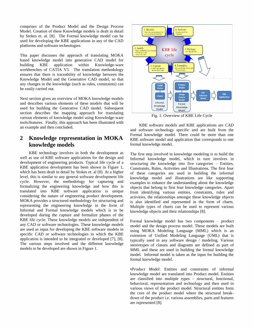
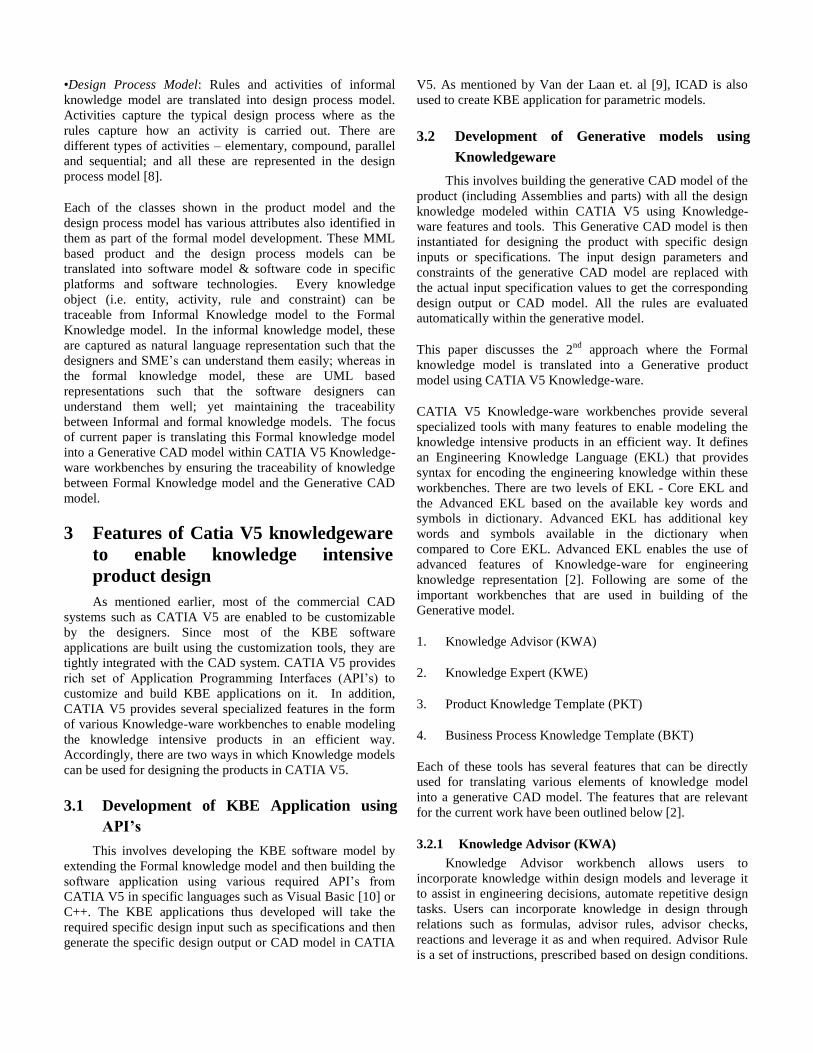
KBE application development has been shown in Figure 1,
which has been dealt in detail by Stokes et. al [8]. At a higher
level, this is similar to any general software development life
cycle. However, the methodology for capturing and
formalizing the engineering knowledge and how this is
translated into KBE software application is unique
considering the nature of engineering product development.
MOKA provides a structured methodology for structuring and
representing the engineering knowledge in the form of
Informal and Formal knowledge models which is to be
developed during the capture and formalize phases of the
KBE life cycle. These knowledge models are independent of
any CAD or software technologies. These knowledge models
are used as input for developing the KBE software models in
specific CAD or software technologies in which the KBE
application is intended to be integrated or developed [7], [8].
The various steps involved and the different knowledge
models to be developed are shown in Figure 1.
Fig. 1: Overview of KBE Life Cycle
KBE software models and KBE applications are CAD
and software technology specific and are built from the
Formal knowledge model. There could be more than one
KBE software model and application that corresponds to one
formal knowledge model.
The first step involved in knowledge modeling is to build the
Informal knowledge model, which in turn involves in
structuring the knowledge into five categories – Entities,
Constraints, Rules, Activities and Illustrations. The first four
of these categories are used in building the informal
knowledge model and illustrations are like supporting
examples to enhance the understanding about the knowledge
objects that belong to first four knowledge categories. Apart
from identifying various entities, constraints, rules and
activities, the relationships amongst these knowledge objects
is also identified and represented in the form of charts.
Multiple types of charts can be used to represent various
knowledge objects and their relationships [8].
Formal knowledge model has two components – product
model and the design process model. These models are built
using MOKA Modeling Language (MML) which is an
extension of Unified Modeling Language (UML) that is
typically used in any software design / modeling. Various
stereotypes of classes and diagrams are defined as part of
MML and these are used in building the formal knowledge
model. Informal model is taken as the input for building the
formal knowledge model.
•Product Model: Entities and constraints of informal
knowledge model are translated into Product model. Entities
are classified into multiple types – structural, functional,
behavioral, representation and technology and then used in
various views of the product model. Structural entities form
the core of the product model where the structural break-
down of the product i.e. various assemblies, parts and features
are represented [8].
•Design Process Model: Rules and activities of informal
knowledge model are translated into design process model.
Activities capture the typical design process where as the
rules capture how an activity is carried out. There are
different types of activities – elementary, compound, parallel
and sequential; and all these are represented in the design
process model [8].
Each of the classes shown in the product model and the
design process model has various attributes also identified in
them as part of the formal model development. These MML
based product and the design process models can be
translated into software model & software code in specific
platforms and software technologies. Every knowledge
object (i.e. entity, activity, rule and constraint) can be
traceable from Informal Knowledge model to the Formal
Knowledge model. In the informal knowledge model, these
are captured as natural language representation such that the
designers and SME’s can understand them easily; whereas in
the formal knowledge model, these are UML based
representations such that the software designers can
understand them well; yet maintaining the traceability
between Informal and formal knowledge models. The focus
of current paper is translating this Formal knowledge model
into a Generative CAD model within CATIA V5 Knowledge-
ware workbenches by ensuring the traceability of knowledge
between Formal Knowledge model and the Generative CAD
model.
3 Features of Catia V5 knowledgeware
to enable knowledge intensive
product design
As mentioned earlier, most of the commercial CAD
systems such as CATIA V5 are enabled to be customizable
by the designers. Since most of the KBE software
applications are built using the customization tools, they are
tightly integrated with the CAD system. CATIA V5 provides
rich set of Application Programming Interfaces (API’s) to
customize and build KBE applications on it. In addition,
CATIA V5 provides several specialized features in the form
of various Knowledge-ware workbenches to enable modeling
the knowledge intensive products in an efficient way.
Accordingly, there are two ways in which Knowledge models
can be used for designing the products in CATIA V5.
3.1 Development of KBE Application using
API’s
This involves developing the KBE software model by
extending the Formal knowledge model and then building the
software application using various required API’s from
CATIA V5 in specific languages such as Visual Basic [10] or
C++. The KBE applications thus developed will take the
required specific design input such as specifications and then
generate the specific design output or CAD model in CATIA
V5. As mentioned by Van der Laan et. al [9], ICAD is also
used to create KBE application for parametric models.
3.2 Development of Generative models using
Knowledgeware
This involves building the generative CAD model of the
product (including Assemblies and parts) with all the design
knowledge modeled within CATIA V5 using Knowledge-
ware features and tools. This Generative CAD model is then
instantiated for designing the product with specific design
inputs or specifications. The input design parameters and
constraints of the generative CAD model are replaced with
the actual input specification values to get the corresponding
design output or CAD model. All the rules are evaluated
automatically within the generative model.
This paper discusses the 2nd
approach where the Formal
knowledge model is translated into a Generative product
model using CATIA V5 Knowledge-ware.
CATIA V5 Knowledge-ware workbenches provide several
specialized tools with many features to enable modeling the
knowledge intensive products in an efficient way. It defines
an Engineering Knowledge Language (EKL) that provides
syntax for encoding the engineering knowledge within these
workbenches. There are two levels of EKL - Core EKL and
the Advanced EKL based on the available key words and
symbols in dictionary. Advanced EKL has additional key
words and symbols available in the dictionary when
compared to Core EKL. Advanced EKL enables the use of
advanced features of Knowledge-ware for engineering
knowledge representation [2]. Following are some of the
important workbenches that are used in building of the
Generative model.
1. Knowledge Advisor (KWA)
2. Knowledge Expert (KWE)
3. Product Knowledge Template (PKT)
4. Business Process Knowledge Template (BKT)
Each of these tools has several features that can be directly
used for translating various elements of knowledge model
into a generative CAD model. The features that are relevant
for the current work have been outlined below [2].
3.2.1 Knowledge Advisor (KWA)
Knowledge Advisor workbench allows users to
incorporate knowledge within design models and leverage it
to assist in engineering decisions, automate repetitive design
tasks. Users can incorporate knowledge in design through
relations such as formulas, advisor rules, advisor checks,
reactions and leverage it as and when required. Advisor Rule
is a set of instructions, prescribed based on design conditions.
Advisor Check is used to analyze the value of specific design
condition. Advisor Check is basically a set of instructions that
are validated whenever there is a change in related
parameters. It will not cause any events. A Reaction is similar
to Advisor Rule except that it’s triggering can be controlled
by a defined event. Changes in the event will cause the
Reaction to trigger. Reaction is designed to create an
associative and reactive model.
3.2.2 Knowledge Expert (KWE)
Similar to KWA, Knowledge Expert workbench allows
users to incorporate knowledge within design models. KWE
defines a way to specify design rules, checks which must be
implemented across the organization so as to ensure best
methods and established standards are followed. We can
create Expert Rules based on design conditions. Rule Set
gathers Expert Rules and Expert Checks. A Rule Base is
created at root level in KWE workbench. Rule Base contains
several Rule Sets related to Product
3.2.3 Product Knowledge Template (PKT)
Product Knowledge Template as the name suggests
enables us to create Templates. These Templates can
encapsulate the design methodology at feature, part and
assembly level. User defined features (UDF) are created at
feature level; Document Templates are created at Part and
Assembly levels. UDF’s are similar to Power copies with
additional capability of encapsulation. We can edit the
templates easily through parameters as we do in part design.
3.2.4 Business Process Knowledge Template (BKT)
BKT is oriented towards design process. We can define
design process sequence and execute the design process.
Technological objects are created in BKT and it contains
behaviors. Knowledge elements like rule, check etc can be
incorporated through behaviors.
4 Translating MOKA knowledge
model into Generative CAD model in
Catia V5 knowledgeware
There have been several attempts made earlier, as
reported by Emberey et. al, [3] and Skarka et. al. [7], to
create KBE applications in CATIA V5 by referring to
MOKA based knowledge models. Most of these approaches
use Informal Knowledge Model for building the KBE
application. Skarka et. al. [7] describes the way the Informal
knowledge model has been used for building the generative
model in CATIA V5 Knowledge-ware. The focus of this
paper is to logically extend the Formal Knowledge model to
build the generative CAD model by maintaining the
traceability beyond Formal Knowledge Model. Various
elements of Knowledge-ware tools such as Rules, Checks
and Reactions has been mapped to various elements of
Formal Knowledge model. Details of this mapping and other
mechanisms for translating Formal Knowledge Models into
CATIA V5 Generative Model have been explained in the
following sections.
4.1 Translation Method
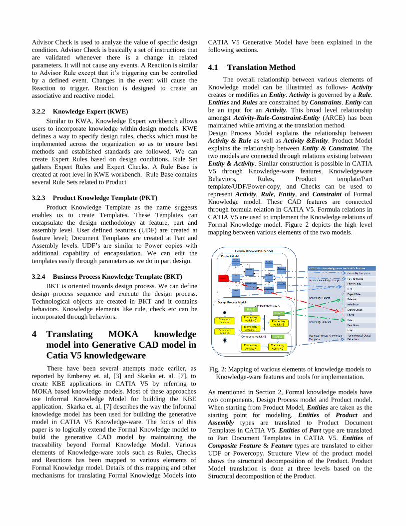
The overall relationship between various elements of
Knowledge model can be illustrated as follows- Activity
creates or modifies an Entity. Activity is governed by a Rule.
Entities and Rules are constrained by Constraints. Entity can
be an input for an Activity. This broad level relationship
amongst Activity-Rule-Constraint-Entity (ARCE) has been
maintained while arriving at the translation method.
Design Process Model explains the relationship between
Activity & Rule as well as Activity &Entity. Product Model
explains the relationship between Entity & Constraint. The
two models are connected through relations existing between
Entity & Activity. Similar construction is possible in CATIA
V5 through Knowledge-ware features. Knowledgeware
Behaviors, Rules, Product template/Part
template/UDF/Power-copy, and Checks can be used to
represent Activity, Rule, Entity, and Constraint of Formal
Knowledge model. These CAD features are connected
through formula relation in CATIA V5. Formula relations in
CATIA V5 are used to implement the Knowledge relations of
Formal Knowledge model. Figure 2 depicts the high level
mapping between various elements of the two models.
Fig. 2: Mapping of various elements of knowledge models to
Knowledge-ware features and tools for implementation.
As mentioned in Section 2, Formal knowledge models have
two components, Design Process model and Product model.
When starting from Product Model, Entities are taken as the
starting point for modeling. Entities of Product and
Assembly types are translated to Product Document
Templates in CATIA V5. Entities of Part type are translated
to Part Document Templates in CATIA V5. Entities of
Composite Feature & Feature types are translated to either
UDF or Powercopy. Structure View of the product model
shows the structural decomposition of the Product. Product
Model translation is done at three levels based on the
Structural decomposition of the Product.
1. Composite Features and Features Level
2. Part Level
3. Assembly Level
Level 1: Composite Features and Features Level
For every Features and Composite Feature, all of the
relevant Rules and Constraints are first identified. All the
identified Rules are translated to Expert / Advisor Rules.
Similarly, all the identified Constraints are translated to
Expert/Advisor Checks. The attributes of Constraints and
Rules are translated to parameters in Advisor Check/Expert
Check and Expert/ Advisor Rules respectively. These Expert
/Advisor Rules and Expert/Advisor Checks are implemented
at the part document template level where the corresponding
feature or composite feature resides. Corresponding to this
feature or composite feature, either a UDF or a power copy
is created such that the CAD geometry construction
methodology of the UDF/Powercopy is in line with the
Representation view of the feature or composite feature. The
Expert/Advisor Rules themselves will modify the related
parameters that in turn drive the CAD geometry. The
sequence of activities are indirectly realized though the
dependencies of the parameters as far as possible. For
Activities that could not be realized through the parameter
dependencies, it is realized by creating Advisor Reactions,
whose triggering can be controlled. Advisor reactions can
also drive CAD geometries. The Expert/Advisor Rules or
Advisor Reactions can modify the CAD geometry through
the top level parameters of the UDFs and Powercopies which
in turn will embed within them the construction methodology
as per the Representation View.
Level 2: Part Level
Next level of structural hierarchy is Part Entity. The Part
Entity is mapped to Part Document Template in CATIA V5.
All the attributes, Constraints, Rules associated with the Part
Entity are identified. Rules and Constraints are translated to
Expert/Advisor Rules and Expert/Advisor Checks
respectively in CATIA V5. These Expert/Advisor Rules and
Expert/Advisor Checks are implemented at the respective
part document template level. The interaction between Expert
/Advisor Rules, Expert/Advisor Checks, Advisor reaction
and UDFs/Powercopies is similar to that mentioned in
“Composite Features and Features Level” section. The
CAD geometry construction methodology of this part
document template is in line with the Representation view of
the Part Entity.
Level 3: Assembly Level
Next higher level of structural decomposition is Assembly
Entity. The Assembly Entity is mapped to Product Document
Template in CATIA V5. All the Attributes, Constraints,
Rules associated with the Assembly Entity are identified.
Rules and Constraints are translated to Expert/Advisor Rules
and Expert/Advisor Checks respectively in CATIA V5.
These Expert/Advisor Rules and Expert/Advisor Checks are
implemented at the respective product document template
level. The attributes of Constraints are translated to
parameters in Advisor Check/Expert Check. The Expert/
Advisor Rules themselves will modify the related parameters
that in turn drive the assembly level instances and their
relationships. The sequence of activities are indirectly
realized though the dependencies of the parameters as far as
possible. For Activities that could not be realized through the
parameter dependencies, are realized by creating Advisor
Reactions at product template level, whose triggering can be
controlled. Advisor reactions can also drive the assembly
level instances and their relationships. The assembly
construction methodology (instances and their relationships)
will be such that it is in line with the Representation view of
the Assembly Entity.
While starting from Product Model, Entity-Rules-
Constraints are created first which to some extent captures
the Activity flow through parameter dependencies. Then for
the Activities that are not captured through parameter
dependencies, Advisor Reactions are used to complete ARCE
relationship.
This approach is a template based approach, where the entire
assembly structure is created upfront with all the embedded
rules and constraints where as the previous approach is a
creation from scratch approach where the CAD geometries
are created when the technological object is instantiated.
As mentioned in the previous section traceability has been
the key consideration in arriving at the mapping methodology
between Formal knowledge model and CATIA V5
Knowledge ware features. Various knowledge objects such
as Activity, Entity, Constraint, Rules that are present in the
Informal knowledge Model, could be traceable to the Formal
Knowledge Model. Similar traceability is maintained while
translating Formal Knowledge Models into CATIA V5
Generative Model. At a high level, Product knowledge model
gets translated through PKT and Design process Model gets
translated through BKT. There is a one to one
correspondence between Rule of knowledge model to the
Rule within Knowledge ware. All the Constraints are
mapped to the Checks of Knowledge ware. All the
parameters of Entity, Rule or Constraint are translated as
Parameters of CATIA V5 with proper categorization. Change
in parameter of any CAD geometry is reflected through
dependent parameters because parameters are linked through
formulae. The parameter linkages follow ARCE relationship
thus ensuring traceability.
5 Conclusion
Though Knowledge based engineering approach
stresses more on the re-use of knowledge and the KBE
applications, there have been lots many challenges in
realizing this especially because of frequent
enhancements/changes in the software technology as well as
product development technologies. Structured KBE
application development methodology with traceability of
knowledge across the KBE life cycle will play crucial role in
ensuring that the knowledge is made re-usable over a long
period of time. MOKA based Knowledge modeling
methodology provides a very good foundation in terms of
Informal and Formal knowledge models having very good
traceability amongst them. This paper focuses on logically
extending this to create the generic CAD model within
CATIA V5 by translating Formal Knowledge model; by
ensuring that the knowledge is traceable till the generic CAD
model. Though the CAD model can be generated in many
ways and many other CAD systems, the focus of this paper
was specific to CATIA V5 – Knowledge-ware. However, the
similar approach can be thought of for other CAD systems as
well.
6 References
[1] Bidarra R., Bronsvoort W.F.: Semantic feature
modeling, Computer-Aided Design 32 (2000) 201–225
doi:10.1016/S0010-4485(99)00090-1
[2] Dassault Systemes, http://www.3ds.com/ , CATIA CAD
Software, Version 5 Release 21
[3] Emberey C.L., Milton N.R.: Application of Knowledge
Engineering Methodologies to Support Engineering
Design Application development in Aerospace,
American Institute of Aeronautics and Astronautics,
2007
[4] IBM, http://www.ibm.com/, Rational Rhapsody
Software, Version 7 Release 1
[5] Liu Yong-Jin, Lai Kam-Lung, Dai Gang, and Yuen
Matthew Ming-Fai: A Semantic Feature Model in
Concurrent Engineering, IEEE TRANSACTIONS ON
AUTOMATION SCIENCE AND ENGINEERING,
VOL. 7, NO. 3, JULY 2010
[6] Pinfold M., Chapman Craig, Preston Steve: Knowledge
acquisition and documentation for the development of a
KBE system for automated FE analysis, Int. J.
Knowledge Management Studies, Vol. 2, No. 2, 2008,
163-174 doi:10.1504/IJKMS.2008.018319
[7] Skarka Wojciech: Application of MOKA methodology
in generative model creation using CATIA, Engineering
Applications of Artificial Intelligence, 20, 2007, 677–
690 doi:10.1016/j.engappai.2006.11.019
[8] Stokes, M.: Managing Engineering Knowledge, MOKA:
Methodology and Tools Oriented to Knowledge Based
Engineering Applications, Professional Engineering
Publishing Ltd, London, United Kingdom, 2001
[9] Van der Laan A.H., Van Tooren M.J.L.: Parametric
Modeling of Movables for Structural Analysis,
American Institute of Aeronautics and Astronautics,
2004
[10] Vermeulen B., Van Tooren M.J.L.: Implementation of an
Automated Detailed Design Tool (ADDET) in the
Design Process for FML/Glare Fuselage Panels,
American Institute of Aeronautics and Astronautics,
2007