Embed Size (px)
Citation preview

Gebr. Becker GmbH • 42279 Wuppertal • Germany • Fon +49 202 697 0 • [email protected]
WWW.BECKER-INTERNATIONAL.COM
01/1
9
Operating InstructionsTranslation of the Original German-Language Instructions
ROOTS BOOSTER PUMPSRBP 500/1000/2000
Document number: RBP 1.00 BT EN

2Gebr. Becker GmbH • 42279 Wuppertal • Germany • Fon +49 202 697 0 • [email protected]
WWW.BECKER-INTERNATIONAL.COM
Table of contents
1 Introduction 31.1 Preface 31.2 Warranty 31.3 Customer service 31.4 Maintenance 3
2 Safety instructions 42.1 Symbol explanations 42.2 Intended use 42.3 Approved operating conditions 52.4 Inspection regulations 52.5 General information on safety 52.6 Personnel selection and qualifications 62.7 Hazards due to disregard of safety instructions 62.8 Unauthorised conversion or manufacture of spare parts 62.9 Personal protective equipment 6
3 Transport 73.1 General 73.2 Safety instructions for transport 73.3 Incoming goods and unpacking 73.4 Unloading 73.5 Internal transporting 83.6 Storage 8
4 Start-up and operation 94.1 Electric motor 94.2 Roots vacuum pump 104.3 Additional safety information 104.4 Danger of vacuum pump damage 11
5 Maintenance 125.1 Overview of the components 125.2 Tightness 125.3 Lubricant 125.4 Tightness of the drive shaft feedthrough 135.5 Lubricating oil types and capacities according to the pump size 135.6 Maintenance plan 14
6 Safety measures 156.1 By-pass 15
7 Malfunctions 16
8 Declaration of Conformity 18

3Gebr. Becker GmbH • 42279 Wuppertal • Germany • Fon +49 202 697 0 • [email protected]
WWW.BECKER-INTERNATIONAL.COM
1 Introduction1.1 PrefaceWith this operating manual, we would like to provide the user with useful instructions for safe and proper operation as well as easy maintenance.Anyone assigned with the task of transporting, setting up, starting up or operating our products or subjecting them to maintenance or repairs requires to read and understand the operating manual, the safety regulations and the safety instructions of the individual chapters and sections.If you have any queries, refer to 1.4.
1.2 WarrantyThis operating manual should be read carefully before start-up.No liability is accepted for damage and malfunctions that result from ignoring the operating ins-tructions.Wear parts are not included in the warranty. Warranty claims must be made promptly upon de-tection of the fault and include the order number.
The warranty is rendered void in cases of:• improper handling,• operation other than intended by the operating instruction,• faulty setup,• incorrect or improper layout or connection of the wiring,• not using original spare parts,
1.3 Customer serviceOur customer service is on hand to assist you with any technical questions concerning products and their systematic applications.In case you should have any problems with our products, please contact one of our customer service centres or the responsible representative.When contacting us or ordering spare parts, please provide the data on the type plate.It is guaranteed by the specification of this data that the correct information or needed spare parts are sent to you.
1.4 MaintenanceWe can take over this task for you with trained specialists.
Gebr. Becker GmbH Technical support Spare partsPO Box 25 02 20D-42238 WuppertalTel.: +49 (0)202 / 697 - 0Fax: +49 (0)202 / 66 08 55
Tel.: +49 (0)202 / 697 - 173Fax: +49 (0)202 / 64 44 74
Tel.: +49 (0)202 / 697 - 322Fax: +49 (0)202 / 64 44 74
SERVICE (worldwide) ► www.becker-international.com

4Gebr. Becker GmbH • 42279 Wuppertal • Germany • Fon +49 202 697 0 • [email protected]
WWW.BECKER-INTERNATIONAL.COM
2 Safety instructions2.1 Symbol explanations
Occupational safety symbolThis symbol can be found in the operating manual next to information on occupational safety concerning dangers to life and limb of persons.Always observe the corresponding instructions and be especially attentive and careful.Pass the safety information on to all persons that are assigned to work on the booster pump.In addition, always observe the generally valid safety regulations.
This symbol is displayed in the operating manual next to information that, if ignored, can cause damage to the booster pump and other material assets.
2.2 Intended useRoots vacuum pumps, also known as „Roots blowers“ belonging to the rotary vacuum pumps are used for vacuum pumping and are well-known in industries requiring vacuum procedures for high volume displacement. They are designed for use in high, medium and low vacuum applications and for operating in the pressure range between 10-4 mbar abs. to 100 mbar abs..In most cases it is installed as first stage in a pump line with a backing vacuum pump capable of discharging at ambient pressure with suction pressure of a few millibars.
The roots booster pump RBP is not intended for continuous operation discharging against ambient pressure.
RBP
1 3 42
Application
Liquid separator, Pre-filter, Roots vacuum pump, Backing vacuum pump
The RBP-series has been designed according to the state of the technology and recognised rules of safety technology and has been tested for safety by the manufacturer.
The RBP may be used only in technically fault-free condition by operating personnel, in observance of the valid safety and accident prevention regulations. This also inclu-des the adherence to the maintenance information provided in the operating manual.Operating personnel must have read and understood the information provided in this operating instructions.
Serious health or material damage can occur if:• covers are removed without permission,• the RBP is used not as intended,• the RBP is operated incorrectly,• maintenance is insufficient,• safety equipment is switched off or bridged,• impermissible or improper modifications/conversions are made,• other than original spare parts are used.

5Gebr. Becker GmbH • 42279 Wuppertal • Germany • Fon +49 202 697 0 • [email protected]
WWW.BECKER-INTERNATIONAL.COM
Operation of the RBP-series disregarding the operational conditions listed in this section - is not permitted by the manufacturer, - can endanger the safety of the operator or other persons, - can reduce claims or even completely exclude of all claims towards the manufacturer.
Operation of the air supply systems is prohibited in environments with flammable dusts and gases.
Only air may be used as medium.
2.3 Approved operating conditionsThe following operating conditions must be observed
• ambient pressure: 900-1050 mbar abs.* • ambient temperature: 0°-40°C• intake gas temperature: 0°-40°C• max. motor speed: 3000 1/min (50 Hz), 3600 1/min (60 Hz)
* In case of differing ambient pressures, consult with Gebr. Becker.
2.4 Inspection regulations
Inspections during the initial start-upThe inspections are basically a visual inspection and a function test. You should make sure that the device is in a safe condition and that any faults or damage that may have been caused for instance by improper transport have been rectified.
Recurring inspectionsThe recurring inspections are basically visual inspections and function tests, whereby the condition of components in regards to damages, wear, corrosion or other changes are evaluated as well as the completeness and effectiveness of the safety equipment needs to be determined. A regular electrical inspection is to be carried out according to the respective country-specific safety regulations.
All tests have to be initiated by the operator and executed by an authorised specialist.
2.5 General information on safetyThis operating manual contains basic information that needs to be observed during transportation, set-up, start-up, operation, maintenance and shut-down. For this reason, this operating manual has to be read by the personnel charged with installation assembly as well as the responsible

6Gebr. Becker GmbH • 42279 Wuppertal • Germany • Fon +49 202 697 0 • [email protected]
WWW.BECKER-INTERNATIONAL.COM
technician/operator before assembly and start-up and must always be available at the operation site of the machine/system.Please observe the:
• Accident prevention regulations DGUV regulation 3 “Electrical systems and components”• Norm EN 60204 T1• Specific national codes/regulations
2.6 Personnel selection and qualificationsPersonnel responsible for instalation, operation, maintenance and inspection must be sufficiently qualified for this work. The scope of responsibility, competencies and monitoring of personnel has to be exactly specified by the operator. If the personnel do not have the required knowledge, they have to be trained and instructed. This can be carried out by the manufacturer/supplier on request by operator, if necessary. The operator also has to ensure that the content of the operating instructions is fully understood by the operating personnel.
2.7 Hazards due to disregard of safety instructionsDisregarding the safety instructions can cause hazard to persons and material damage. Disre-garding the safety information can lead to loss of all liability claims.
2.8 Unauthorised conversion or manufacture of spare partsConversions or modifications are permitted only after given support by customer service. Original spare parts and accessories authorised by the manufacturer serve to ensure safety. Using other parts may render void the liability in case of any trouble.
2.9 Personal protective equipment
Personal protective equipment (PPE) must generally be worn when setting up, main-taining and servicing.

7Gebr. Becker GmbH • 42279 Wuppertal • Germany • Fon +49 202 697 0 • [email protected]
WWW.BECKER-INTERNATIONAL.COM
3 Transport3.1 GeneralThe transport responsibility lies with the respective transport company up to the delivery site and/or installation site.
3.2 Safety instructions for transport
- Hoists may be attached only to points intended for this; inserted supports have to be secured against slipping for example.
- Ropes, chains or other hoists have to be equipped with safety hooks. - No frayed or chafed ropes may be used. - Ropes and chains may not have knots. - Ropes and chains may not rest against sharp edges. - Suspension devices of individual system parts may not be used to transport further parts.
- Use only ropes and chains with sufficient load capacity. - Use only hoists with sufficient load capacity. - Never lift loads above and over persons.
3.3 Incoming goods and unpackingPlease check at delivery of the roots booster pump whether there is any obvious transport damage:
• Externally detectable damage has to be certified on the freight papers by the driver.• Hidden damage can be detected only after the packaging has been removed. • For insurance purposes, damage has to be notified in writing to the delivering shipping
company within seven days.• Check the system for completeness of the delivery. The identity number can be found on
the type plate.• If motor is not flange mounted rotate the pump shaft manually to ensure that it turns smoothly .• Check that no particles are inside the pump vacuum chamber.
3.4 Unloading
Observe the safety instructions and the accident prevention regulations which are applicable in the respective country!Unloading may only be performed by experienced persons who are familiar with the hoist and any necessary auxiliary equipment.The weight specifications can be found on the delivery papers.General lifting accessories should be used for unloading.

8 Gebr. Becker GmbH • 42279 Wuppertal • Germany • Fon +49 202 697 0 • [email protected]
WWW.BECKER-INTERNATIONAL.COM
When lifting and setting-up pumps or pump motor units, sling placement must follow indi-cations in figure.During this operation, care must be taken that the belts do not damage any part of the ma-chine.
3.5 Internal transportingIn case of internal transporting ensure that roots vacuum pump, motor and accessory parts are not damaged by mechanical shock.
3.6 StorageAfter unloading, the packaged units need to be stored until set up.If they are to be stored for an extended period, then the packed pumps should not be unpacked.
The following guidelines apply for storage: - Store in a dry place.Make sure the pumps are not stored outside.Also make sure the floor of the storage area is dry during the storage period.
- In the event of prolonged immobilisation, add oil to each of the two housings, up to the normal level.
- Portect the interior of the body and the pistons and machined parts with anti-corrosive oil.
- Rotate the shaft of the pump and the motor from time to time to avoid any defects on the bearings.

9Gebr. Becker GmbH • 42279 Wuppertal • Germany • Fon +49 202 697 0 • [email protected]
WWW.BECKER-INTERNATIONAL.COM
4 Start-up and operation - Do not start-up before reading and understanding this operating instructions. - Only qualified personnel must be allowed to start up and service this equipment. - Disconnect power supply when working on the machine or any of its components. - Use proper safety elements and equipment to avoid hazards due to the use and installation of this machine.
- Keep body and clothing away from rotating machine unit, inlet and outlet port or exhaust vent of circulating gases.
- The noise level requires ear protection. - Generated heat may cause burns. Prevent an inadvertently contact with hot pump surfaces.
- Protective transmission devices must always be correctly placed and installed. If the unit is to be disassemble of any reason, it must be shut down previously.
- Pump, motor and accessory fixtures must be periodically checked. - In order to avoid electrostatic discharge, electrical grounding must be installed on the vacuum pump or the unit of which it is a part.
- Do not use the pump for any purpose other than that for which it is intended. - An emergency shut-off must be provided to shut down the pump whenever necessary. - All Flange covers must be removed prior to pipe installation. - Only start up the pump when suction flanges and drive flanges are connected properly. - Never start up the pump if discharge port is closed or discharge line is blocked. - Blower cleaning and degreasing must be carried out under cold machine conditions and with non- toxic or aggressive substances, liquids or mixtures. Some of these liquids may react violently to heat.
- Insure that the thermal radiation generated by the vacuum pump can be dissipated sufliciently.
- Operate the vacuum pump with a suitable discharge line. The discharge line must be properly connected with the pump outlet flange and should have an inclination to prevent condensate backstreaming into the vacuum pump.
4.1 Electric motor
Check if the nominal motor voltage corresponds to the mains voltage.Check the electrical connections on the motor.Start briefly the motor, checking that the motor turns in the direction of the arrow on the pump.
If not, disconnect the pump from the mains and interchange two mains phases.Run the motor, check for working stability and correct balance.

10Gebr. Becker GmbH • 42279 Wuppertal • Germany • Fon +49 202 697 0 • [email protected]
WWW.BECKER-INTERNATIONAL.COM
4.2 Roots vacuum pump • If the motor is not flange mounted rotate the pump shaft manually to ensure that it turns
smoothly. If any resistance is encountered, then inlet, outlet and drive connection flanges should be loosened as well as motor base screws, if necessary. The interior of the machine must also be checked for particles. The roots vacuum pump must be tension free.
• The pipes connected to the pump must be perfectly cleaned to prevent particles from entering the pump. Make shure that no particles (grains, clots,...), objects (washers, wirring pieces,...) or liquids are ingested through the intake port of the vacuum pump. We recommend the installation of a protective grid on the inlet for start-up and operation.
• For oil filling, see section 5.5 lubricating oil.• Check oil levels in oil sumps of both housing parts.• Check the oil level in the transparent lubricator to verify that the drive shaft feedthrough is
leakproof.• Verify that the oil filling cap and drain plug are leakproof.• Check that all safety elements are assembled with the correct feedthrough (relief valve,
retaining valve, stop valves, safety devices, etc.).• For start up of pumping system, start the backing pump befor starting the booster vacuum
pump or at least both at the same time.
Never start up the booster vacuum pump first!
• During the first few minutes of operation, large amounts of foam will be visible in the oil window. A normal reaction due to oil degassing.
• Booster pump stop. Stop the booster vacuum pump and backing vacuum pump at the same time. If necessary, stop the booster vacuum pump first and then stop the backing vacuum pump.
Never stop the backing vacuum pump first! NOTE: The backing vacuum pump must be aired to ambient pressure after it is stopped.
Check:• Noise and transmission stability of the booster vacuum pump and of the coupling or trans-
mission system.• Housing temperature with respect to unusually high temperatures.• That the drive shaft feedthrough is leakproof.• Smooth rotary deceleration after stopping.• Easy manual shaft rotation of the booster vacuum pump after the test run.• The oil-level.
4.3 Additional safety information • Avoid exposing any parts of the human body or clothing to the vacuum.• The gas flow in the discharge line must not be restricted in any way or blocked.• Prevent the discharge line from being pressurized, e.g. as a part of a piping system.• The vaccum pump must only be operated at rotor speeds approved by the manufacturer,
see point 2.3 of this manual.• In case of using a frequency converter for regulating the motor speed, protect the vacuum

11Gebr. Becker GmbH • 42279 Wuppertal • Germany • Fon +49 202 697 0 • [email protected]
WWW.BECKER-INTERNATIONAL.COM
pump against an over-speeding.• Observe the required standards for carrying out the electrical connections.• Make sure that the vacuum pump cannot run-up automatically after it has been shut-down
(e.g. caused by a sudden power failer or motor over-temperature).• Remove any oil that escaped during maintenance work or during operation to avoid a slip-
ping risk.• Never open the oil-fill or oil-drain plug in presence of vacuum or while the pump is running.
There is a danger that oil may be splashed out.
4.4 Danger of vacuum pump damage• When setting up keep in mind that the pump must be easily accessible for future mainte-
nance tasks.• The installation location must be dry and the foundation must provide a stable support for
the vacuum pump. Angles >1° (above horizontal position) have to be avoided in order to ensure a safe operation (e.g. oil supply, proper Bypass and proper sealing function).
• During pump operation check the oil level in the sight glasses and the transparent lubricator regulary.
• Do not use the vacuum pump in combination with a backing pump that has an ultimate pressure above appr. 10 mbar abs. in order to prevent excessively high pump temperatures.
• The use of compensators on intake and on discharge side is recommended to prevent the transfer of vibration to the connected pipe system.
• Do not use the vacuum pump for the suction of abrasive or adhesive medium (powder, dust, particles, ...) or condensable vapours. This can lead to deposits in pump vacuum chamber and can cause high temperatures and exessive required motor power due to friction. Use adequate seperator or filter equipment.

12Gebr. Becker GmbH • 42279 Wuppertal • Germany • Fon +49 202 697 0 • [email protected]
WWW.BECKER-INTERNATIONAL.COM
5 MaintenanceThe work listed in this chapter is necessary to ensure perfect operation of the vacuum pump over a long period of time.It also serves to maintain the service life and reliability of the vacuum pump.
In particular, the regular cleaning of all the surfaces is necessary to prevent an over-heating or a possible ignition of deposits on hot surfaces.
All maintenance and cleaning work has to be carried out only by suitable trained perso-nal. Let the pump always cool down first before doing any maintenance or servicework. Use protective gloves during maintenance work.The voltage of the entire system has to be shut down during maintenance and service. It needs be ensured that the rotors of the roots vacuum pump stand idle. Check whe-ther there is any residual voltage on the terminal board of the respective drive that is caused by the generative operation while the device comes to a stop.
5.1 Overview of the components
Oil sight glass Filler plug Oil drain plug Pressure port Transparent lubricator Oil drain plug (rotary shaft seal) Bleed plug Suction port
��� �
�� � ���
�
5.2 TightnessAll the components of our roots vacuum pumps are manufactured and sealed to be leakproof under high vacuum conditions. Guaranteed tightness is 10-3 mbar l/s . The tightness system in the drive shaft sealing is located in a cap inside the drive side sump, consisting of two inverted shaft seal rings. The clearance between the lip seal rings is filled with oil to ensure tightness and lubricate the shaft seal rings.
Check oil drain plug gaskets and oil sight glass gaskets.Check that the shaft feedthrough seal is perfectly leakproof. The transparent lubricator must always be maintained at a constant level. If the oil level is low, this indicates that the shaft seal rings are worn. ►see 5.4
5.3 LubricantRoots vacuum pumps are lubricated by splash lubrication and therefore consume minimum amounts of oil. Nevertheless, the oil level must be checked regularly.
Oil levelThe correct oil level is shown in the drawing (half of oil sight glass).

13Gebr. Becker GmbH • 42279 Wuppertal • Germany • Fon +49 202 697 0 • [email protected]
WWW.BECKER-INTERNATIONAL.COM
Exceeding the filling limit will cause high oil temperatures and pump malfunction. in addition, oil may also leak into the compression chamber. Therefore it is essential to avoid exceeding the filling limit.
Oil changeThe machine must be stopped and at ambient pressure before carrying out this operation.
• During break-in (500 service hours)Oil should be changed after 500 service hours.
• During normal working operationOil should be changed once a year if the pumped gas is clean. If working conditions are not optimum, oil should be changed more frequently.NOTE: We recommend taking and examining oil samples at 4,000 working hours, on the basis of the identified oil aging oil changing periods will be determined.
5.4 Tightness of the drive shaft feedthrough
1
4
2
3
Oil filling: - Remove the transparent lubricator (1). - Open the bleed plug (4). - Fill oil slowly at point (3) using a funnel. - While filling, open the oil drain plug (2) so that a small quantity of oil is released. Place a collecting tray under the oil drain plug. When filling begins, the plug will release the air trapped inside the chamber. This will completely bleed the chamber interior.
- The oil entering will push the air downwards. When the oil begins to flow out of the oil drain plug (2), wait until it is a continuous flow in order to ensure that all the air has been released.
- Once there is a continuous flow of oil, close the plug (2) and check that the chamber is full through the opening (4).
- Close the bleed plug (4), replace the transparent lubricator (1) and fill it approximately half.
- During the first few minutes of operation, the oil level in the trans-parent lubricator may drop a millimeter or two. Observe it.
- The lubricator level must then be kept constant. - Oil can be added to the lubricator while the machine is in opera-tion, at no risk.
- If the oil level drops by one sight level per month, this indicates that the shaft seal rings are worn. The machine should be stopped and the shaft seal rings replaced.
- The shaft seal rings slide on a hardened and ground surface ring. When replacing the rings, check that the ring is in perfect condition. If the shaft seal ring path is visible on the ring, the ring must be replaced.
5.5 Lubricating oil types and capacities according to the pump sizeThe pumps are delivered without any oil fill. Before start-up, they must be filled with the appropriate of the following lubricating oils:

14Gebr. Becker GmbH • 42279 Wuppertal • Germany • Fon +49 202 697 0 • [email protected]
WWW.BECKER-INTERNATIONAL.COM
2 2
� ��
Size Total 1)
Gear + bearing
Bearing
Shaft500 1.68 1.05 0.56 0.07
1000 2.53 1.65 0.8 0.08
2000 4.79 3.11 1.58 0.10 1) Specified in liters
Use mineral oil BECKER LUBE G 220!
Do not vary oil quality as, in certain cases, a mixture of different oils can cause problems. Oil barrels must remain airtight until they are used to prevent absorption of air humidity.
5.6 Maintenance planTo
the
first
2 h
ours
of
oper
atio
n
Eve
ry w
eek
To th
e fir
st 5
00 h
ours
of o
pera
tion
Afte
r 100
0 h
or e
very
yea
r
Afte
r 400
0 h
or e
very
yea
r
Afte
r 800
0 h
or e
very
yea
r
Afte
r 160
00 h
or e
very
2 y
ears
Afte
r 200
00 h
or e
very
3 y
ears
Oil level control X XChange oil X XCheck and clean the motor fan and motor cooling fins. (dependent on ambient conditions)
X
Aspiraction Filter Control 1)
- Clean- Replace
XX
Non-return valve 1)
- Control leakage and wear - Replace
XX
Shaft seal ring change X 2)
By-pass valve - Control it operates correctly X 2)
X 2)
GENERAL INSPECTIONReview by a specialist authorised by Gebr. Becker
X 2)
1) No direct part of the pump2) This maintenance points can only be done by a service partner authorized by Gebr. Becker
15Gebr. Becker GmbH • 42279 Wuppertal • Germany • Fon +49 202 697 0 • [email protected]
WWW.BECKER-INTERNATIONAL.COM
6 Safety measures6.1 By-pass This prevents roots vacuum pump overload. The valve is weight-adjusted.The by-pass ensures maximum differential pressure between outlet of the backing pump and suction. In other words, the maximum differential pressure admissible for the roots vacuum pump is never exceeded. The roots vacuum pump starts up when the backing vacuum pump reaches the required pressure (higher pump unit speed).
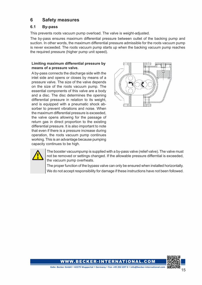
Limiting maximum differential pressure by means of a pressure valve.A by-pass connects the discharge side with the inlet side and opens or closes by means of a pressure valve. The size of the valve depends on the size of the roots vacuum pump. The essential components of this valve are a body and a disc. The disc determines the opening differential pressure in relation to its weight, and is equipped with a pneumatic shock ab-sorber to prevent vibrations and noise. When the maximum differential pressure is exceeded, the valve opens allowing for the passage of return gas in direct proportion to the existing differential pressure. lt is also important to note that even if there is a pressure increase during operation, the roots vacuum pump continues working. This is an advantage because pumping capacity continues to be high.
The booster vacuumpump is supplied with a by-pass valve (relief valve). The valve must not be removed or settings changed. If the allowable pressure differntial is exceeded, the vacuum pump overheats.The proper function of the bypass valve can only be ensured when installed horizontally.We do not accept responsibility for damage if these instructions have not been followed.

16Gebr. Becker GmbH • 42279 Wuppertal • Germany • Fon +49 202 697 0 • [email protected]
WWW.BECKER-INTERNATIONAL.COM
7 MalfunctionsIf you hear any unusual noises or observe temperatures above normal, shut down the machine immediately, check the causes of the anomaly and initiate appropriate measures to eliminate the cause of malfunktion.Only qualified personnel is permitted to perform maintenance, service or other works at the vacuum pump.Before carrying out works at the vacuum pump, the system must be switched off and secured against restart.Do not start up the machine until the the system troubleshooting has been finnished and the system can operate under appropriate conditions.
Malfunction Cause RectificationThe blower makes a strange noise
The bolts at the base are loose Tighten themlncorrect alignment of pump and electric motor
Align the electric motor
Loose bolts in the coupling Tighten themProblem with the start-up elec-tric motor (bearings, imbal-ance)
Check electric motor, if neces-sary repair or replace
Grinding of the pistons Grinding of the piston against the housing or against each other
Excessive dirt, clean the interi-or of the compression chamber
Grinding of the pistons with the lateral end faces of the housing parts
Excessive load, measure op-erating pressures and perform appropriate measures if the max. differential pressure is exceeded
Excessive clearance in the gear wheels
Clean and dry the gears to measure the clearance. Con-sult our technical service.
Excessive vibration Excessive clearance in the bearings
Measure to lerances and change bearings if necessary
lmbalance in the rotating pis-tons
Due to deposits or wear and tear of pistons. Clean or change the pistons
Overheating Excessive operating pressure Measure the pressure and compare with the one specified in the offer and perform appro-priate measures if the max. differtial pressure is exceeded
Excessive oil level Check the oil level, drain oil if necessary
Exessive oil viscosity Check the specifications of the oil.
Excessive piston tolerance Check the piston tolerances and and consult our technical service

17Gebr. Becker GmbH • 42279 Wuppertal • Germany • Fon +49 202 697 0 • [email protected]
WWW.BECKER-INTERNATIONAL.COM
Malfunction Cause RectificationOil leaks in the compression chamber or in the condensates hole
High oil level Check oil level, drain oil if nec-essary
Worn sealings Replace the worn sealing el-ements
lncorrectly tightened caps or oil sight glasses
Check they are correctly tight-ened and watertight
Oil leakage from the drive shaft tightness system
Seal rings from the drive shaft tightness system are worn.
Turn off the machine and re-place the seal rings.
Insufficient aspiration flow Wrong size of the vacuum pump
Check the performance curve and contact the technical ser-vice
Excessive tolerances in the pistons
Check the tolerances of the pistons and consult our tech-nical service
Dirty aspiration filter Clean the filter cartridge
Excessive pressure or over-loading of the blower
Check the blower pressure and rotating speed. If necessary, take appropriate measures to ensure permissible operation
Excessive power consumption Excessive operating pressure Measure the operating pres-sures and compare them with the ones indicated in the offer
Excessive lubricant Check oil level, drain oil if nec-essary
Machine wear and tear After 3 years or 20000 hours of operation, a general inspection by an authorised expert is rec-ommended

18Gebr. Becker GmbH • 42279 Wuppertal • Germany • Fon +49 202 697 0 • [email protected]
WWW.BECKER-INTERNATIONAL.COM
8 Declaration of Conformity
GB
EC Declaration of Conformityaccording to 2006/42/EC (Machinery Directive)
Manufacturer: Gebr. Becker GmbH Hölker Feld 29-31 D-42279 WuppertalDocumentationmanager:
We hereby declare that the machines of the model series:
conform with all pertinent regulations of the EC Machinery Directive 2006/42/EC and the EMC Guideline 2014/30/EU.
The following harmonised norms were applied:
EN 1012-2: 1996+A1:2009EN ISO 12100: 2010EN 60204-1: 2006+A1:2009EN ISO 2151: 2004
Wuppertal, 3 December 2018
Ulrich Wilkesmann Dr.-Ing. Sven Hilfert Managing Director Sales Managing Director Engineering
Original Declaration of Conformity Translation of the Declaration of Conformity
Dr. Mark Schlieper
RBP 500 RBP 1000 RBP 2000