Embed Size (px)
Citation preview
•GI0UP 21
TRANSMISSION
CONfiNfS Page
PAIT 1—MANUAL TRANSMISSION . . . . . . . . 3 DESCRIPTION 1 SERVICE DIAGNOSIS 1 SERVICE PROCEDURES—3-SPEED 3 SERVICE PROCEDURES—4-SPEED 15 SPECIFICATIONS AND TIGHTENING
REFERENCE . . . . . . (In Rear of the Manual)
MODEL A -745 Description
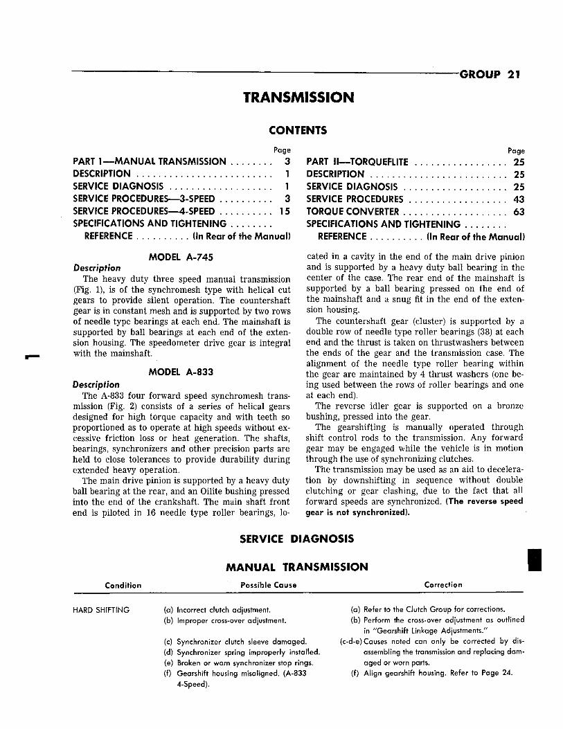
The heavy duty three speed manual transmission (Fig. 1), is of the synchromesh type with helical cut gears to provide silent operation. The countershaft gear is in constant mesh and is supported by two rows of needle type bearings at each end. The mainshaft is supported by ball bearings at each end of the extension housing. The speedometer drive gear is integral with the mainshaft.
MODEL A -833 Description
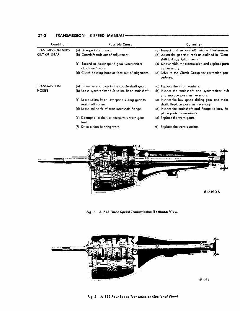
The A-833 four forward speed synchromesh transmission (Fig. 2) consists of a series of helical gears designed for high torque capacity and with teeth so proportioned as to operate at high speeds without excessive friction loss or heat generation. The shafts, bearings, synchronizers and other precision parts are held to close tolerances to provide durability during extended heavy operation.
The main drive pinion is supported by a heavy duty ball bearing at the rear, and an Oilite bushing pressed into the end of the crankshaft. The main shaft front end is piloted in 16 needle type roller bearings, lo-
Page
PART II—TORQUEPLITE . . . . . . . . . . . . . . . . . 25 DESCRIPTION . . . . . . . . . . . . . . 25 SERVICE DIAGNOSIS 25 SERVICE PROCEDURES 43 TORQUE CONVERTER 63 SPECIFICATIONS AND TIGHTENING
REFERENCE (In Rear of the Manual)
cated in a cavity in the end of the main drive pinion and is supported by a heavy duty ball bearing in the center of the case. The rear end of the mainshaft is supported by a ball bearing pressed on the end of the mainshaft and a snug fit in the end of the extension housing.
The countershaft gear (cluster) is supported by a double row of needle type roller bearings (38) at each end and the thrust is taken on thrustwashers between the ends of the gear and the transmission case. The alignment of the needle type roller bearing within the gear are maintained by 4 thrust washers (one being used between the rows of roller bearings and one at each end).
The reverse idler gear is supported on a bronze bushing, pressed into the gear.
The gearshifting is manually operated through shift control rods to the transmission. Any forward gear may be engaged while the vehicle is in motion through the use of synchronizing clutches.
The transmission may be used as an aid to deceleration by downshifting in sequence without double clutching or gear clashing, due to the fact that all forward speeds are synchronized. (The reverse speed gear is not synchronized).
SERVICE DIAGNOSIS
Condit ion
MANUAL TRANSMISSION Possible C a u s e Correction
HARD SHIFTING (a) Incorrect clutch adjustment. (b) Improper cross-over adjustment.
(c) Synchronizer clutch sleeve damaged. (d) Synchronizer spring improperly installed. (e) Broken or worn synchronizer stop rings. (f) Gearshift housing misaligned. (A-833
4-Speed).
(a) Refer to the Clutch Group for corrections. (b) Perform the cross-over adjustment as outlined
in "Gearshift Linkage Adjustments." (c-d-e) Causes noted can only be corrected by dis
assembling the transmission and replacing damaged or worn parts,
(f) Align gearshift housing. Refer to Page 24.
21-2 TRANSMISSION—3-SPEED MANUAL
Condit ion Possible Cause Correction
TRANSMISSION SLIPS (a) Linkage interference. (a) Inspect and remove all linkage interferences. OUT O F GEAR (b) Gearshift rods out of adjustment. (b) Adjust the gearshift rods as outlined in "Gear
shift Linkage Adjustments." (c) Second or direct speed gear synchronizer (c) Disassemble the transmission and replace parts
clutch teeth worn. as necessary. (d) Clutch housing bore or face out of alignment. (d) Refer to the Clutch Group for correction pro
cedures.
TRANSMISSION (a) Excessive end play in the countershaft gear. (a) Replace the thrust washers. NOISES (b) Loose synchronizer hub spline fit on mainshaft. (b) Inspect the mainshaft and synchronizer hub
and replace parts as necessary. (c) Loose spline fit on low speed sliding gear to (c) Inspect the low speed sliding gear and main-
mainshaft spline. shaft. Replace parts as necessary.
(d) Loose spline fit of rear mainshaft flange. (d) Inspect the mainshaft and flange splines. Replace parts as necessary.
(e) Damaged, broken or excessively worn gear (e) Replace the worn gears. teeth.
(0 Drive pinion bearing worn. (f) Replace the worn bearing.
F /g . ? • — A - 7 4 5 Three S p e e d Transmission (Sectional View)
F/g. 2 — A - 8 3 3 Four S p e e d Transmission (Sectional View)
TRANSMISSION—3-SPEED MANUAL 21-3
PART 1 A-745 3-SPEED MANUAL TRANSMISSION
SERVICE PROCEDURES Gearshift Linkage Adjustment
(1) With the 2nd and 3rd control rod disconnected from the lever on the column and the 1st and reverse control rod disconnected from the transmission lever, position both transmission levers in neutral. (The neutral detent balls must be engaged to make this adjustment correctly.) To check this, start the engine (with clutch disengaged) then release the clutch slowly.
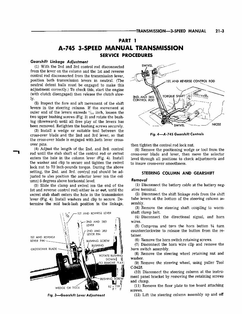
(2) Inspect the fore and aft movement of the shift levers in the steering column. If the movement at outer end of the levers exceeds 1j1Q inch, loosen the two upper bushing screws (Fig. 3) and rotate the bushing (downward) until all free play of the levers has been removed. Retighten the bushing screws securely.
,(3) Install a wedge or suitable tool between the cross-over blade and the 2nd and 3rd lever, so that the cross-over blade is engaged with J>oth lever crossover pins.
(4) Adjust the length of the 2nd. and 3rd. control rod until the stub shaft of the control rod or swivel enters the hole in the column lever (Fig. 4). Install the washer and clip to secure and tighten the swivel lock nut to 70 inch-pounds torque. During the above setting, the 2nd. and 3rd. control rod should be adjusted to also position the selector lever (on the column) 5 degrees above horizontal level.
(5) Slide the clamp and swivel (on the end of the 1st and reverse control rod) either in or out, until the swivel stub shaft enters the hole in the transmission lever (Fig. 4). Install washers and clip to secure. Determine the mid back-lash position in the linkage,
Fig. 3—Gearshift Lever Adjustment
Fig. 4—A-745 Gearshift Controls
then tighten the control rod lock nut. (6) Remove the positioning wedge or tool from the
cross-over blade and lever, then move the selector level through all positions to check adjustments and to insure cross-over smoothness.
STEERING COLUMN AND GEARSHIFT
Removal (1) Disconnect the battery cable at the battery neg
ative terminal. (2) Disconnect the shift linkage rods from the shift
tube levers at the bottom of the steering column assembly.
(3) Remove the steering shaft coupling to worm-shaft clamp bolt.
(4) Disconnect the directional signal, and horn wires.
(5) Compress and turn the horn button Vk turn counterclockwise to release the button from the retainer.
(6) Remove the horn switch retaining screws. (7) Disconnect the horn wire clip and remove the
horn switch assembly. (8) Remove the steering wheel retaining nut and
washer. (9) Remove the steering wheel, using puller Tool
C-3428. (10) Disconnect the steering column at the instru
ment panel bracket by removing the retaining screws and clamp.
(11) Remove the floor plate to toe board attaching screws.
(12) Lift the steering column assembly up and off
21-4 TRANSMISSION—3-SPEED MANUAL
SWITCH RETAINING SCREWS (3)
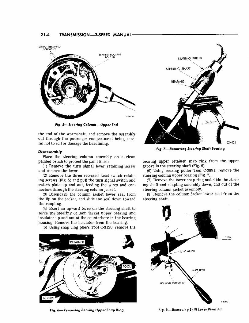
F i g . 5—Steer ing Column—Upper End
the end of the wormshaft, and remove the assembly out through the passenger compartment being careful not to soil or damage the headlining.
Disassembly Place the steering column assembly on a clean
padded bench to protect the paint finish. (1) Remove the turn signal lever retaining screw
and remove the lever. (2) Remove the three recessed head switch retain
ing screws (Fig. 5) and pull the turn signal switch and switch plate up and out, feeding the wires and connectors through the steering column jacket.
(3) Disengage the column jacket lower seal from the lip on the jacket, and slide the seal down toward the coupling.
(4) Exert an upward force on the steering shaft to force the steering column jacket upper bearing and insulator up and out of the counterbore in the bearing housing. Remove the insulator from the bearing.
(5) Using snap ring pliers Tool C-3128, remove the
F i g . 6 — R e m o v i n g Bearing Upper Snap Ring
F/g. 7 — R e m o v i n g Steering Shaft Bearing
bearing upper retainer snap ring from the upper groove in the steering shaft (Fig. 6).
(6) Using bearing puller Tool C-3891, remove the steering column upper bearing (Fig. 7).
(7) Remove the lower snap ring and slide the steering shaft and coupling assembly down, and out of the steering column jacket assembly.
(8) Remove the column jacket lower seal from the steering shaft.
62x453
F i g . 8—Removing Shift Lever Pivot Pin
TRANSMISSION—3-SPEED MANUAL 21-5
SPACER N Y L O N LOWER SUPPORT CUP
WASHER
BUSHING RETAINING SCREWS (2)
N U T (2)
CUP ATTACHING SCREWS (3)
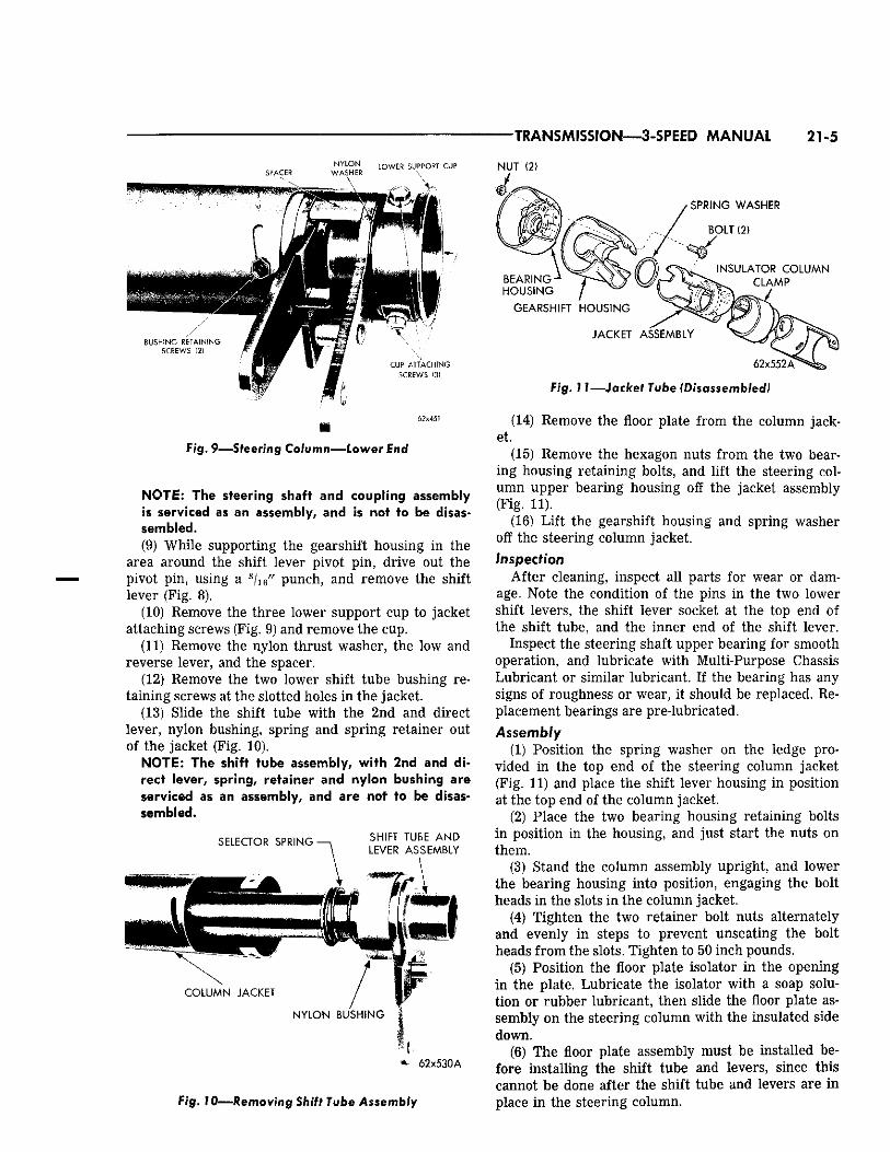
Fig. 9 — S t e e r i n g Column—Lower End
NOTE: The steering shaft and coupling assembly is serviced as an assembly, and is not to be disassembled. (9) While supporting the gearshift housing in the
area around the shift lever pivot pin, drive out the pivot pin, using a 3 / 1 6 " punch, and remove the shift lever (Fig. 8).
(10) Remove the three lower support cup to jacket attaching screws (Fig. 9) and remove the cup.
(11) Remove the nylon thrust washer, the low and reverse lever, and the spacer.
(12) Remove the two lower shift tube bushing retaining screws at the slotted holes in the jacket.
(13) Slide the shift tube with the 2nd and direct lever, nylon bushing, spring and spring retainer out of the jacket (Fig. 10).
NOTE: The shift tube assembly, with 2nd and direct lever, spring, retainer and nylon bushing are serviced as an assembly, and are not to be disassembled.
S E L E C T O R S P R I N G • S H I F T T U B E A N D
L E V E R A S S E M B L Y
1 C O L U M N J A C K E T
N Y L O N B U S H I N G
6 2 x 5 3 0 A
S P R I N G W A S H E R
B O L T (2)
I N S U L A T O R C O L U M N
C L A M P
Fig. 10—Removing Shift Tube Assembly
B E A R I N G H O U S I N G
G E A R S H I F T H O U S I N G
J A C K E T A S S E M B L Y
6 2 x 5 5 2 ^
Fig. 11—Jacket Tube (Disassembled)
(14) Remove the floor plate from the column jacket.
(15) Remove the hexagon nuts from the two bearing housing retaining bolts, and lift the steering column upper bearing housing off the jacket assembly (Fig. 11).
(16) Lift the gearshift housing and spring washer off the steering column jacket. Inspection
After cleaning, inspect all parts for wear or damage. Note the condition of the pins in the two lower shift levers, the shift lever socket at the top end of the shift tube, and the inner end of the shift lever.
Inspect the steering shaft upper bearing for smooth operation, and lubricate with Multi-Purpose Chassis Lubricant or similar lubricant. If the bearing has any signs of roughness or wear, it should be replaced. Replacement bearings are pre-lubricated. Assembly
(1) Position the spring washer on the ledge provided in the top end of the steering column jacket (Fig. 11) and place the shift lever housing in position at the top end of the column jacket.
(2) Place the two bearing housing retaining bolts in position in the housing, and just start the nuts on them.
(3) Stand the column assembly upright, and lower the bearing housing into position, engaging the bolt heads in the slots in the column jacket.
(4) Tighten the two retainer bolt nuts alternately and evenly in steps to prevent unseating the bolt heads from the slots. Tighten to 50 inch pounds.
(5) Position the floor plate isolator in the opening in the plate. Lubricate the isolator with a soap solution or rubber lubricant, then slide the floor plate assembly on the steering column with the insulated side down.
(6) The floor plate assembly must be installed before installing the shift tube and levers, since this cannot be done after the shift tube and levers are in place in the steering column.
21-6 TRANSMISSION—3-SPEED MANUAL'
NOTE: Metal to metal working surfaces should be lubricated with Multi-Purpose lubricant to facilitate installation. (7) Turn the nylon bushing on the shift tube, (Fig.
10) so the two holes in the bushing are aligned with the centerline of the 2nd and 3rd speed shift lever, then slide the shift tube and lever assembly through the jacket tube and into the bearing housing.
(8) Install the spacer around the selector lever so it rests against the 2nd and 3rd speed shift lever.
(9) Install the low and reverse lever. Then install the nylon washer, centering it over the end of the shift tube.
(10) Install the lower support-cup in the jacket (Fig. 9), while holding pressure against the cup to overcome the selector spring load, start the three support cup retaining screws, and tighten to 30 inch pounds.
(11) Loosely enter the lower bushing retaining screws through the slots in the jacket, and into the nylon bushing (Fig. 10).
(12) Rotate the nylon bushing to where all play at the shift levers and spacers is eliminated, but no binding occurs. With the bushing in this position, tighten the two bushings to jacket screws to 30 inch pounds torque.
NOTE: The shift tube must be free to slide up and down in its bushing. No binding is permissable. (13) The gearshift lever insulator should be exam
ined, and if any wear or damage is evident, it should be pulled off the lever and replaced.
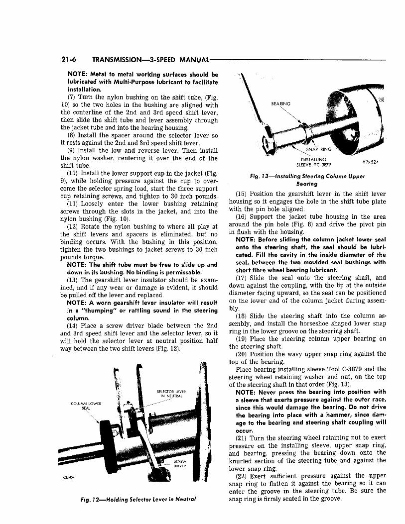
NOTE: W orn gearshift lever insulator wi l l result in a "thumping" or rattling sound in the steering column. (14) Place a screw driver blade between the 2nd
and 3rd speed shift lever and the selector lever, so it will hold the selector lever at neutral position half way between the two shift levers (Fig. 12).
SELECTOR LEVER IN NEUTRAL
COLUMN LOWER SEAL
1
\ f . i SCREW " ? • D"IVEP
62x454
\
8 3 A R i f - ' G
• • F X 1 \
\ S N A P R I N G
I N S T A L L I N G SLEEVE # C 3879
i
62x52i
Pig. 12—Holding Se lector l e v e r In Neutral
Pig. 13—Installing Steering Column Upper Bearing
(15) Position the gearshift lever in the shift lever housing so it engages the hole in the shift tube plate with the pin hole aligned.
(16) Support the jacket tube housing in the area around the pin hole (Fig. 8) and drive the pivot pin in flush with the housing.
NOTE: Before sliding the column jacket lower seal onto the steering shaft, the seal should be lubricated. Fill the cavity in the inside diameter of the seal, between the two moulded seal bushings with short fibre wheel bearing lubricant. (17) Slide the seal onto the steering shaft, and
down against the coupling, with the lip at the outside diameter facing upward, so the seal can be positioned on the lower end of the column jacket during assembly.
(18) Slide the steering shaft into the column assembly, and install the horseshoe shaped lower snap ring in the lower groove on the steering shaft.
(19) Place the steering column upper bearing on the steering shaft.
(20) Position the wavy upper snap ring against the top of the bearing.
Place bearing installing sleeve Tool C-3879 and the steering wheel retaining washer and nut, on the top of the steering shaft in that order (Fig. 13).
NOTE: Never press the bearing into position with a sleeve that exerts pressure against the outer race, since this would damage the bearing. Do not drive the bearing into place with a hammer, since damage to the bearing and steering shaft coupling will occur. (21) Turn the steering wheel retaining nut to exert
pressure on the installing sleeve, upper snap ring, and bearing, pressing the bearing down onto the knurled section of the steering tube and against the lower snap ring.
(22) Exert sufficient pressure against the upper snap ring to flatten it against the bearing so it can enter the groove in the steering tube. Be sure the snap ring is firmly seated in the groove.
TRANSMISSION—3-SPEID MANUAL 21-7
(23) Place the insulator over the bearing, then slide the steering shaft, bearing and insulator downward into the counterbore provided in the bearing housing.
(24) Position the directional switch assembly in the bearing housing, while feeding the turn signal and horn wires through the steering column and out through the opening provided in the column jacket.
(25) Place the switch plate over the switch, and install the three switch retaining screws (Fig. 5). Tighten screws to 24 inch pounds torque.
(26) Position the turn signal lever in the assembly, sighting down through the hole in the switch to align the screw hole, and install the lever attaching screw. Tighten screws to 24 inch pounds torque.
Installation (In the Vehicle) (1) Insert the column and jacket tube assembly
through the floor pan opening, being careful not to soil or damage the headlining.
(2) Position the clamp on the coupling and with the master splines on the worn shaft and coupling aligned, engage the column coupling with the steering gear worm shaft.
(3) Loosely fasten the steering column jacket to the instrument panel bracket with the clamp and the two attaching screws. Be sure the tab on the clamp is entered in the locating slot in the column jacket.
(4) With the steering shaft coupling clamp in position on the coupling assembly, install the clamp bolt so that it engages the groove in the wormshaft. Tighten clamp bolt nut to 30 foot pounds torque.
(5) Position the steering jacket assembly so the steering shaft coupling is centered at the midpoint of its travel.
NOTE: With the steering column jacket clamp bolts loose, "free travel" in the steering shaft coupling along with the slotted bolt holes in the column clamp; permits the jacket and steering shaft assembly to move up and down (axially). (6) Move the column assembly up or down in the
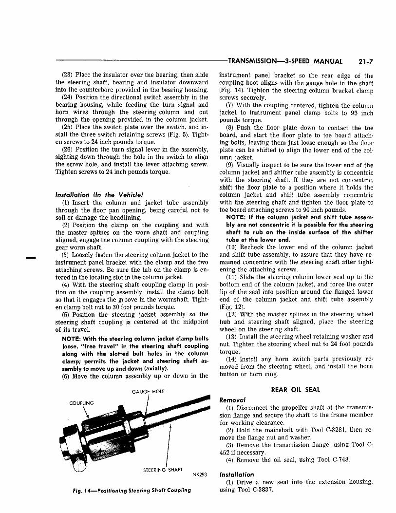
G A U G E H O L E
Fig. 74—Positioning Steering Shaft Coupling
instrument panel bracket so the rear edge of the coupling boot aligns with the gauge hole in the shaft (Fig. 14). Tighten the steering column bracket clamp screws securely.
(7) With the coupling centered, tighten the column jacket to instrument panel clamp bolts to 95 inch pounds torque.
(8) Push the floor plate down to contact the toe board, and start the floor plate to toe board attaching bolts, leaving them just loose enough so the floor plate can be shifted to align the lower end of the column jacket.
(9) Visually inspect to be sure the lower end of the column jacket and shifter tube assembly is concentric with the steering shaft. If they are not concentric, shift the floor plate to a position where it holds the column jacket and shift tube assembly concentric with the steering shaft and tighten the floor plate to toe board attaching screws to 90 inch pounds.
NOTE: If the column jacket and shift tube assembly are not concentric it is possible for the steering shaft to rub on the inside surface of the shifter tube at the lower end.' (10) Recheck the lower end of the column jacket
and shift tube assembly, to assure that they have remained concentric with the steering shaft after tightening the attaching screws.
(11) Slide the steering column lower seal up to the bottom end of the column jacket, and force the outer lip of the seal into position around the flanged lower end of the column jacket and shift tube assembly (Fig. 12).
(12) With the master splines in the steering wheel hub and steering shaft aligned, place the steering wheel on the steering shaft.
(13) Install the steering wheel retaining washer and nut. Tighten the steering wheel nut to 24 foot pounds torque.
(14) Install any horn switch parts previously removed from the steering wheel, and install the horn button or horn ring.
REAR OIL SEAL
Remove/ (1) Disconnect the propeller shaft at the transmis
sion flange and secure the shaft to the frame member for working clearance.
(2) Hold the mainshaft with Tool C-3281, tKfen remove the flange nut and washer.
(3) Remove the transmission flange, using Tool C-452 if necessary.
(4) Remove the oil seal, using Tool C-748.
Installation (1) Drive a new seal into the extension housing,
using Tool C-3837.
21-8 TRANSMISSION—3-SPEED MANUAL-
(2) Install the transmission flange, washer and nut. (3) Reconnect the propeller shaft and tighten the Tighten nut to 175 foot-pounds torque. flange nuts to 30 foot-pounds torque.
MAJOR SERWIC1NG 3-SPEED MANUAL A-745
Removal IMPORTANT: To remove the transmission, it will be necessary to first remove the torsion bar rear anchor crossmember and rubber isolators. Refer to Group 2, "Torsion Bar Rubber Isolator," then remove the transmission as follows: (1) Drain the lubricant from the transmission. (2) Disconnect the propeller shaft, speedometer ca
ble and housing and the gearshift control rods. Remove speedometer cable (pinion comes out with cable) with hand so that housing is not crushed.
(3) Remove the back-up light switch leads (if so equipped).
(4) Install engine support fixture C-3487, mounting firmly into the holes in the side frame members with the support ends up against the underside of the oil pan flange.
(5) Raise the engine slightly with the support fixture. Disconnect transmission extension housing from the removable center crossmember.
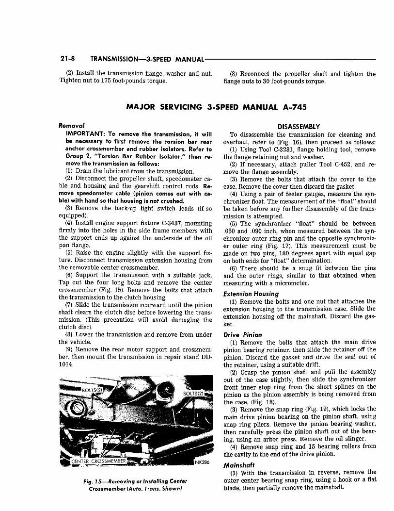
(6) Support the transmission with a suitable jack. Tap out the four long bolts and remove the center crossmember (Fig. 15). Remove the bolts that attach the transmission to the clutch housing.
(7) Slide the transmission rearward until the pinion shaft clears the clutch disc before lowering the transmission. (This precaution will avoid damaging the clutch disc).
(8) Lower the transmission and remove from under the vehicle.
(9) Remove the rear motor support and crossmember, then mount the transmission in repair stand DD-1014.
Fig. 15—Removing or Installing Center C r o s s m e m b e r (Auto. Trans. Shown!
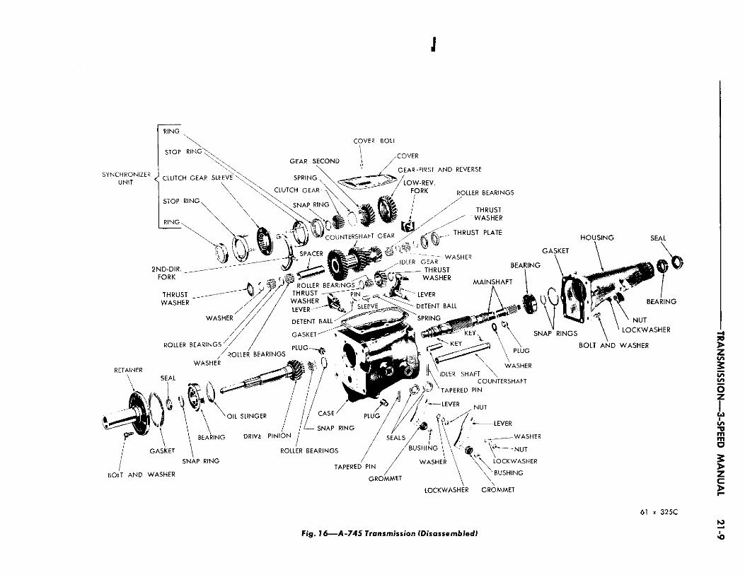
DISASSEMBLY To disassemble the transmission for cleaning and
overhaul, refer to (Fig. 16), then proceed as follows: (1) Using Tool C-3281, flange holding tool, remove
the flange retaining nut and washer. (2) If necessary, attach puller Tool C-452, and re
move the flange assembly. (3) Remove the bolts that attach the cover to the
case. Remove the cover then discard the gasket. (4) Using a pair of feeler gauges, measure the syn
chronizer float. The measurement of the "float" should be taken before any further disassembly of the transmission is attempted.
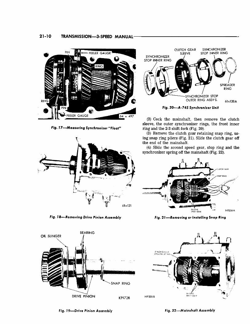
(5) The synchronizer "float" should be between .050 and .090 inch, when measured between the synchronizer outer ring pin and the opposite synchronizer outer ring (Fig. 17). This measurement must be made on two pins, 180 degrees apart with equal gap on both ends for "float" determination.
(6) There should be a snug fit between the pins and the outer rings, similar to that obtained when measuring with a micrometer.
Extension Housing (1) Remove the bolts and one nut that attaches the
extension housing to the transmission case. Slide the extension housing off the mainshaft. Discard the gasket.
Drive Pinion (1) Remove the bolts that attach the main drive
pinion bearing retainer, then slide the retainer off the pinion. Discard the gasket and drive the seal out of the retainer, using a suitable drift.
(2) Grasp the pinion shaft and pull the assembly out of the case slightly, then slide the synchronizer front inner stop ring from the short splines on the pinion as the pinion assembly is being removed from the case, (Fig. 18).
(3) Remove the snap ring (Fig. 19), which locks the main drive pinion bearing on the pinion shaft, using snap ring pliers. Remove the pinion bearing washer, then carefully press the pinion shaft out of the bearing, using an arbor press. Remove the oil slinger.
(4) Remove snap ring and 15 bearing rollers from the cavity in the end of the drive pinion.
Mainshaft (1) With the transmission in reverse, remove the
outer center bearing snap ring, using a hook or a flat blade, then partially remove the mainshaft.
J
COVER BOLT
SYNCHRONIZER ,
UNIT <
C O V E R
GEAR-FIRST A N D REVERSE
N U T
L O C K W A S H E R
B O L T A N D W A S H E R
BOLT A N D WASHER
T A P E R E D P I N
G R O M M E T
W A S H E R
B U S H I N G \ \ <' A X\^~ N U T
W A S H E R \ \ \ L O C K W A S H E R
B U S H I N G
L O C K W A S H E R G R O M M E T
61 x 3 2 5 C
Fig. 16—A-745 Transmission (Disassembled)
21-10 TRANSMISSION—3-SPEED MANUAL
Fig. 1 7 — M e a s u r i n g Synchronizer "Float"
61x121
S Y N C H R O N I Z E R
S T O P I N N E R R I N G
C L U T C H G E A R S Y N C H R O N I Z E R S L E E V E S T O P I N N E R R I N G
S P R E A D E R
R I N G
- S Y N C H R O N I Z E R S T O P
O U T E R R I N G A S S Y ' S .
Fig. 2 0 — A - 7 4 5 Synchronizer Unit
61x120 A
(2) Cock the mainshaft, then remove the clutch sleeve, the outer synchronizer rings, the front inner ring and the 2-3 shift fork (Fig. 20).
(3) Remove the clutch gear retaining snap ring, using snap ring pliers (Fig. 21). Slide the clutch gear off the end of the mainshaft.
(4) Slide the second speed gear, stop ring and the synchronizer spring off the mainshaft (Fig. 22).
V ~ ^ , C L U T C H GEAR
N Y 8 5 4 A
F i g . 7 8 — R e m o v i n g Drive Pinion Assembly Fig. 2 7 — R e m o v i n g or Installing Snap Ring
Fig. 79—Dr ive Pinion Assembly Fig. 22—Mainshaft Assembly
TRANSMISSION—3-SPEED MANUAL 21-11
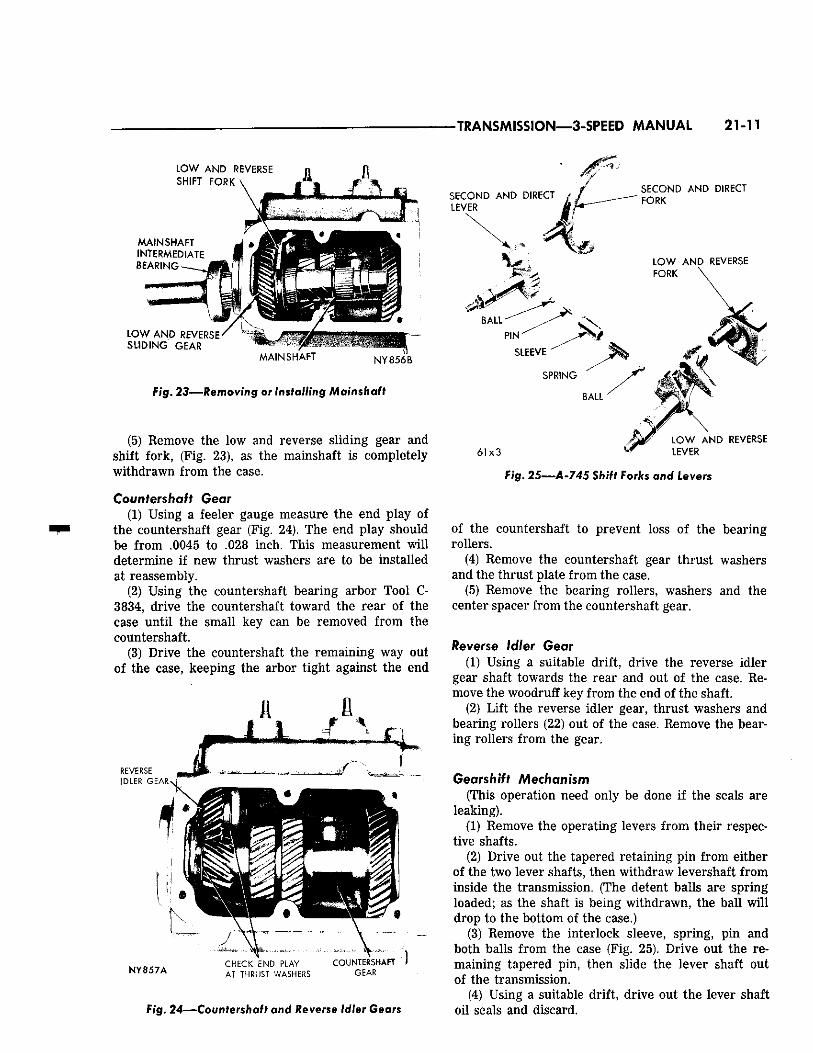
L O W A N D REVERSE n SHIFT FORK
M A I N S H A F T INTERMEDIATE B E A R I N G -
L O W A N D REVERSE S L I D I N G GEAR
M A I N S H A F T NY856B
Fig. 23—Removing or Installing Mainshaft
(5) Remove the low and reverse sliding gear and shift fork, (Fig. 23), as the mainshaft is completely withdrawn from the case.
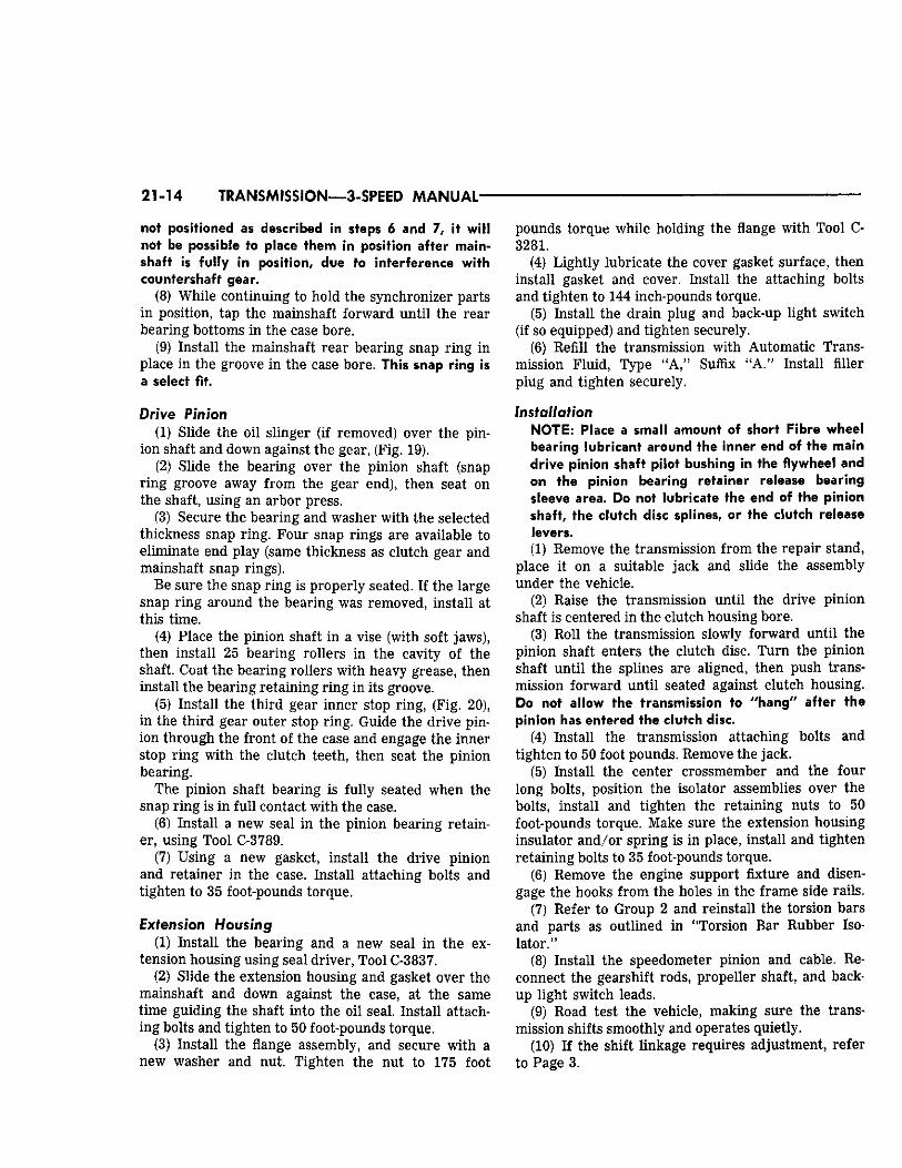
Countershaft Gear (1) Using a feeler gauge measure the end play of
the countershaft gear (Fig. 24). The end play should be from .0045 to .028 inch. This measurement will determine if new thrust washers are to be installed at reassembly.
(2) Using the countershaft bearing arbor Tool C-3834, drive the countershaft toward the rear of the case until the small key can be removed from the countershaft.
(3) Drive the countershaft the remaining way out of the case, keeping the arbor tight against the end
N Y 8 5 7 A CHECK END PLAY COUNTERSHAFT AT THRUST WASHERS GEAR
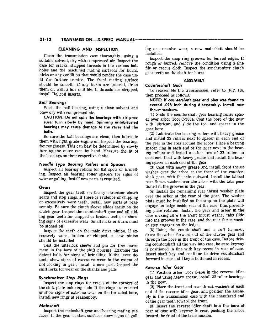
SECOND A N D DIRECT LEVER
SECOND A N D DIRECT FORK
L O W A N D REVERSE FORK
61x3 f L O W A N D REVERSE
LEVER
F i g . 24—Countershaft and Reverse Idler Gears
Fig. 25—A-745 Shift Forks and Levers
of the countershaft to prevent loss of the bearing rollers.
(4) Remove the countershaft gear thrust washers and the thrust plate from the case.
(5) Remove the bearing rollers, washers and the center spacer from the countershaft gear.
Reverse Idler Gear (1) Using a suitable drift, drive the reverse idler
gear shaft towards the rear and out of the case. Remove the woodruff key from the end of the shaft.
(2) Lift the reverse idler gear, thrust washers and bearing rollers (22) out of the case. Remove the bearing rollers from the gear.
Gearshift Mechanism (This operation need only be done if the seals are
leaking). (1) Remove the operating levers from their respec
tive shafts. (2) Drive out the tapered retaining pin from either
of the two lever shafts, then withdraw levershaft from inside the transmission. (The detent balls are spring loaded; as the shaft is being withdrawn, the ball will drop to the bottom of the case.)
(3) Remove the interlock sleeve, spring, pin and both balls from the case (Fig. 25). Drive out the remaining tapered pin, then slide the lever shaft out of the transmission.
(4) Using a suitable drift, drive out the lever shaft oil seals and discard.
21-12 TRANSMISSION—3-SPEED MANUAL
CLEANING AND INSPECTION Clean the transmission case thoroughly, using a
suitable solvent, dry with compressed air. Inspect the case for cracks, stripped threads in the various bolt holes and the machined mating surfaces for burrs, nicks or any condition that would render the case unfit for further service. The front mating surface should be smooth; if any burrs are present, dress them off with a fine mill file. If threads are stripped, install Helicoil inserts.
Ball Bearings Wash the ball bearing, using a clean solvent and
blow dry with compressed air. CAUTION: Do not spin the hearings with air pressure; turn slowly by hand. Spinning unlubricated bearings may cause damage to the races and the balls. Be sure the ball bearings are clean, then lubricate
them with light grade engine oil. Inspect the bearings for roughness. This can best be determined by slowly turning the outer race by hand. Measure the fit of the bearings on their respective shafts.
Needle Type Bearing Rollers and Spacers Inspect all bearing rollers for flat spots or brinell-
ing. Inspect all bearing roller spacers for signs of wear or galling. Install new parts as required.
Gears Inspect the gear teeth on the synchronizer clutch
gears and stop rings. If there is evidence of chipping or excessively worn teeth, install new parts at reassembly. Be sure the clutch sleeve slides easily on the clutch gear. Inspect the countershaft gear and all sliding gear teeth for chipped or broken teeth, or showing signs of excessive wear. Small nicks or burrs must be stoned off.
Inspect the teeth on the main drive pinion. If excessively worn, broken or chipped, a new pinion should be installed.
Test the interlock sleeve and pin for free movement in the bore of the shift housing. Examine the detent balls for signs of brinelling. If the lever detents show signs of excessive wear to the extent of not locking in gear, install a new part. Inspect the shift forks for wear on the shanks and pads.
Synchronizer Slop Rings Inspect the stop rings for cracks at the corners of
the shift plate indexing slots. If the rings are cracked or show signs of extreme wear on the threaded bore, install new rings at reassembly.
Mainshaft Inspect the mainshaft gear and bearing mating sur
faces. If the gear contact surfaces show signs of gall
ing or excessive wear, a new mainshaft should be installed.
Inspect the snap ring grooves for burred edges. If rough or burred, remove the condition using a fine file or crocus cloth. Inspect the synchronizer clutch gear teeth on the shaft for burrs.
ASSEMBLY Countershaft Gear
To reassemble the transmission, refer to (Fig. 16), then proceed as follows:
NOTE: If countershaft gear end play was found to exceed .028 inch during disassembly, install new thrust washers. (1) Slide the countershaft gear bearing roller spac
er over arbor Tool C-3834. Coat the bore of the gear with lubricant and slide the tool and spacer in the gear bore.
(2) Lubricate the bearing rollers with heavy grease and install 22 rollers next to spacer in each end of the gear in the area around the arbor. Place a bearing spacer ring in each end of the gear next to the bearing rollers and install another row of 22 rollers in each end. Coat with heavy grease and install the bearing spacer in each end of the gear.
(3) Coat with heavy grease and install front thrust washer over the arbor at the front of the countershaft gear, with the tabs outward. Install the tabbed rear thrust washer over the arbor with the tabs positioned in the grooves in the gear.
(4) Install the remaining rear thrust washer plate over the arbor at the rear of the gear. The washer plate must be installed so the step on the plate will engage on ledge inside rear of the case, thus preventing plate rotation. Install the gear and arbor in the case making sure the front thrust washer tabs slide into the grooves in the case, and the rear thrust washer step engages on the ledge.
(5) Using the countershaft and a soft hammer, drive the arbor forward out of the cluster gear and through the bore in the front of the case. Before driving countershaft all the way into case, be sure keyway is positioned in line with key recess in rear of case. Insert shaft key and continue to drive countershaft forward in case until key is bottomed in recess.
Reverse Idler Gear (1) Position arbor Tool C-464 in the reverse idler
gear and using heavy grease, install 22 roller bearings in the gear.
(2) Place the front and rear thrust washers at each end of the reverse idler gear, and position the assembly in the transmission case with the chamfered end of the gear teeth toward the front.
(3) Insert the reverse idler shaft into the bore at rear of case with keyway to rear, pushing the arbor toward the front of the transmission.
TRANSMISSION—3-SPEED MANUAL 21-13
(4) With keyway aligned with recess in case, drive the shaft forward, inserting key before the keyway is obscured. Continue driving shaft forward until key seats in recess.
Gearshift Mechanism To install the gearshift mechanism, refer to (Fig.
25), then proceed as follows: (1) Place two new shift lever shaft seals centered
in their bores in the case. Using Tool C-3766, drive both seals into the case, until the tool bottoms.
(2) Install seal protector, Tool C-3767, on the end of low and reverse lever shaft, then slide the shaft into the rear boss of the case and through the seal. Lock in position with the tapered pin. Turn the lever until the center detent is in line with the interlock bore.
(3) Slide the interlock sleeve in its bore in the case followed by one of the interlock balls. Install the interlock spring and pin.
(4) Place the remaining interlock ball on top of the interlock spring, using Tool C-3765, (Fig. 26). (A good method of installing the second ball is to stick the ball in the tool recess by means of lubricant, then use the tool to position the ball on the detent spring.)
(5) Install seal protector Tool C-3767, on the second and high lever shaft, depress the interlock ball, using Tool C-3765 and at the same time install the second and high lever into the fully seated position, with the center detent aligned with the detent ball. Remove the tool. Secure the lever shaft with the remaining tapered pin.
(6) Install the operating levers, install and tighten the retaining nuts securely.
(7) Place the low and reverse fork in the lever shaft, with the offset toward rear of transmission.
T O O L
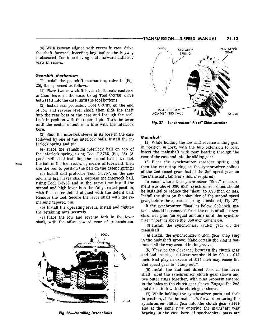
S P R E A D E R
S P R I N G
2 N D S P E E D G E A R
6 1 x 4
li
! \
I N S E R T S H I M
A G A I N S T T H I S F A C E
Fig. 26—Installing Detent Bails
•Map ' 4 . V .Jj'ru 6 4 x 4 9 8
Fig. 27—Synchronizer "Float™ Shim Location
Mainshaft (1) While holding the low and reverse sliding gear
in position in fork, with the hub extension to rear, insert the mainshaft with rear bearing through the rear of the case and into the sliding gear.
(2) Place the synchronizer spreader spring, and then the rear stop ring on the synchronizer splines of the 2nd speed gear. Install the 2nd speed gear on the mainshaft, (and/or shims if required).
In cases where the synchronizer "float" measurement was above .090 inch, synchronizer shims should be installed to reduce the "float" to .090 inch or less. Install the shim on the shoulder of the second speed gear, before the spreader spring is installed, (Fig. 27).
If the synchronizer "float" is below .050 inch, material should be removed from the ends of all six synchronizer pins (an equal amount) until the synchronizer "float" is above the .050 inch dimension.
(3) Install the synchronizer clutch gear on the mainshaft.
(4) Install the synchronizer clutch gear snap ring in the mainshaft groove. Make certain the ring is bottomed all the way around in the groove.
(5) Measure the clearance between the clutch gear and 2nd speed gear. Clearance should be .004 to .014 inch. End play in excess of .014 inch may cause the 2nd speed gear to "Jump out."
(6) Install the 2nd and direct fork in the lever shaft. Hold the synchronizer clutch gear sleeve and two outer rings together, with pins properly entered in the holes in the clutch gear sleeve. Engage the 2nd and direct fork with the clutch gear sleeve.
(7) While holding the synchronizer parts and fork in position, slide the mainshaft forward, entering the synchronizer clutch gear into the clutch gear sleeve and at the same time entering the mainshaft rear bearing in the case bore. If synchronizer parts are
21-14 TRANSMISSION—3-SPEED MANUAL
not positioned as described in steps 6 and 7, it will not be possible to place them in position after main-shaft is fully in position, due to interference with countershaft gear.
(8) While continuing to hold the synchronizer parts in position, tap the mainshaft forward until the rear bearing bottoms in the case bore.
(9) Install the mainshaft rear bearing snap ring in place in the groove in the case bore. This snap ring is a select fit.
Drive Pinion (1) Slide the oil slinger (if removed) over the pin
ion shaft and down against the gear, (Fig. 19). (2) Slide the bearing over the pinion shaft (snap
ring groove away from the gear end), then seat on the shaft, using an arbor press.
(3) Secure the bearing and washer with the selected thickness snap ring. Four snap rings are available to eliminate end play (same thickness as clutch gear and mainshaft snap rings).
Be sure the snap ring is properly seated. If the large snap ring around the bearing was removed, install at this time.
(4) Place the pinion shaft in a vise (with soft jaws), then install 25 bearing rollers in the cavity of the shaft. Coat the bearing rollers with heavy grease, then install the bearing retaining ring in its groove.
(5) Install the third gear inner stop ring, (Fig. 20), in the third gear outer stop ring. Guide the drive pinion through the front of the case and engage the inner stop ring with the clutch teeth, then seat the pinion bearing.
The pinion shaft bearing is fully seated when the snap ring is in full contact with the case.
(6) Install a new seal in the pinion bearing retainer, using Tool C-3789.
(7) Using a new gasket, install the drive pinion and retainer in the case. Install attaching bolts and tighten to 35 foot-pounds torque.
Extension Housing (1) Install the bearing and a new seal in the ex
tension housing using seal driver, Tool C-3837. (2) Slide the extension housing and gasket over the
mainshaft and down against the case, at the same time guiding the shaft into the oil seal. Install attaching bolts and tighten to 50 foot-pounds torque.
(3) Install the flange assembly, and secure with a new washer and nut. Tighten the nut to 175 foot
pounds torque while holding the flange with Tool C-3281.
(4) Lightly lubricate the cover gasket surface, then install gasket and cover. Install the attaching bolts and tighten to 144 inch-pounds torque.
(5) Install the drain plug and back-up light switch (if so equipped) and tighten securely.
(6) Refill the transmission with Automatic Transmission Fluid, Type "A," Suffix "A." Install filler plug and tighten securely.
Installation NOTE: Place a small amount of short Fibre wheel bearing lubricant around the inner end of the main drive pinion shaft pilot bushing in the flywheel and on the pinion bearing retainer release bearing sleeve area. Do not lubricate the end of the pinion shaft, the clutch disc splines, or the clutch release levers. (1) Remove the transmission from the repair stand,
place it on a suitable jack and slide the assembly under the vehicle.
(2) Raise the transmission until the drive pinion shaft is centered in the clutch housing bore.
(3) Roll the transmission slowly forward until the pinion shaft enters the clutch disc. Turn the pinion shaft until the splines are aligned, then push transmission forward until seated against clutch housing. Do not allow the transmission to "hang" after the pinion has entered the clutch disc.
(4) Install the transmission attaching bolts and tighten to 50 foot pounds. Remove the jack.
(5) Install the center crossmember and the four long bolts, position the isolator assemblies over the bolts, install and tighten the retaining nuts to 50 foot-pounds torque. Make sure the extension housing insulator and/or spring is in place, install and tighten retaining bolts to 35 foot-pounds torque.
(6) Remove the engine support fixture and disengage the hooks from the holes in the frame side rails.
(7) Refer to Group 2 and reinstall the torsion bars and parts as outlined in "Torsion Bar Rubber Isolator."
(8) Install the speedometer pinion and cable. Reconnect the gearshift rods, propeller shaft, and backup light switch leads.
(9) Road test the vehicle, making sure the transmission shifts smoothly and operates quietly.
(10) If the shift linkage requires adjustment, refer to Page 3.
TRANSMISSION—4-SPEED MANUAL 21 15
4-SPEED MANUAL TRANSMISSION MODEL A-833
SERWiCE PROCEDURES
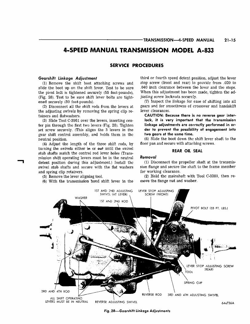
Gearshift Linkage Adjustment (1) Remove the shift boot attaching screws and
slide the boot up on the shift lever. Test to be sure the pivot bolt is tightened securely (55 foot-pounds), (Fig. 28). Test to be sure shift lever bolts are tightened securely (30 foot-pounds).
(2) Disconnect all the shift rods from the levers at the adjusting swivels by removing the spring clip retainers and flatwashers.
(3) Slide Tool C-3951 over the levers, inserting center pin through the first two levers (Fig. 28). Tighten set screw securely. (This aligns the 3 levers in the gear shift control assembly, and holds them in the neutral position.
(4) Adjust the length of the three shift rods, by turning the swivels either in or out until the swivel stub shafts match the control rod lever holes (Transmission shift operating levers must be in the neutral detent position during this adjustment.) Install the swivel stub shafts and secure with the flat washers and spring clip retainers.
(5) Remove the lever aligning tool. (6) With the transmission hand shift lever in the
third or fourth speed detent position, adjust the lever stop screw (front and rear) to provide from .020 to .040 inch clearance between the lever and the stops. When this adjustment has been made, tighten the adjusting screw locknuts securely.
(7) Inspect the linkage for ease of shifting into all gears and for smoothness of crossover and handshift lever clearances.
CAUTION: Because there is no reverse gear interlock, it is very important that the transmission linkage adjustments are correctly performed in order to prevent the possibility of engagement into two gears at the same time. (8) Slide the boot down the shift lever shaft to the
floor pan and secure with attaching screws.
REAR OIL SEAL Removal
(1) Disconnect the propeller shaft at the transmission flange and secure the shaft to the frame member for working clearance.
(2) Hold the mainshaft with Tool C-3281, then remove the flange nut and washer.
Fig. 28—Gearshift Linkage Adjustments
21-16 TRANSMISSION—4-SPEED MANUAL
(3) Remove the transmission flange, using Tool C-452 if necessary.
(4) Remove the oil seal, using Tool C-748. Installation
(1) Drive a new seal into the extension housing,
using Tool C-3837. (2) Install the transmission flange, washer and nut.
Tighten nut to 175 foot-pounds torque. (3) Reconnect the propeller shaft and tighten the
flange nuts to 30 foot-pounds torque.
MAJOR SERVICING 4-SPEED MANUAL A-833 Removal
IMPORTANT: To remove the transmission, it will be necessary to remove the torsion bar rear anchor crossmember and rubber isolators. Refer to Group 2, "Torsion Bar Rubber Isolator," then remove the transmission as follows: (1) Remove the console trim plate. Remove shift
lever boot screws and slide the boot up on the lever. Shift the transmission into reverse, lubricate lever opening in lower boot and push boot down over bolt heads, unscrew the two bolts and remove shift lever.
(2) Drain the lubricant from the transmission. (3) Disconnect the propeller shaft, speedometer ca
ble, and pinion. When removing the speedometer cable, care should be used, so as not to crush the housing. Remove by hand.
(4) Disconnect the left hand exhaust pipe (dual exhaust) from the exhaust manifold.
(5) Disconnect the parking brake control cable. (6) Disconnect the back-up light switch leads at the
connector. (If so equipped.) (7) Install the engine support fixture C-3487, en
gaging the hooks in the holes in the frame side members. Be sure the support ends are up against the underside of the oil pan flange.
(8) Raise the engine slightly with the support fixture. Disconnect transmission extension housing from the removable center crossmember.
(9) Support the transmission with a suitable jack. Tap out the four long bolts and remove the center crossmember (Fig. 15). Remove the bolts that attach the transmission to the clutch housing.
(10) Rotate the transmission until the shift housing and stub lever clear, then slide the transmission toward the rear until the main drive pinion shaft clears the clutch disc, before lowering the transmission. (This will avoid damaging the clutch disc.)
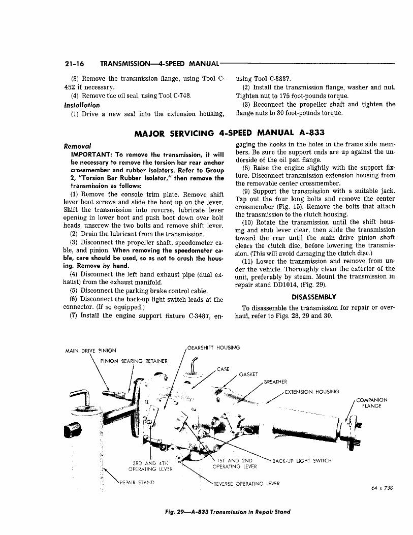
(11) Lower the transmission and remove from under the vehicle. Thoroughly clean the exterior of the unit, preferably by steam. Mount the transmission in repair stand DD1014, (Fig. 29).
DISASSEMBLY
To disassemble the transmission for repair or overhaul, refer to Figs. 28, 29 and 30.
6 4 x 7 3 8
Fig. 29—A-833 Transmission in Repair Stand
TRANSMISSION—4-SPEED MANUAL 21-17
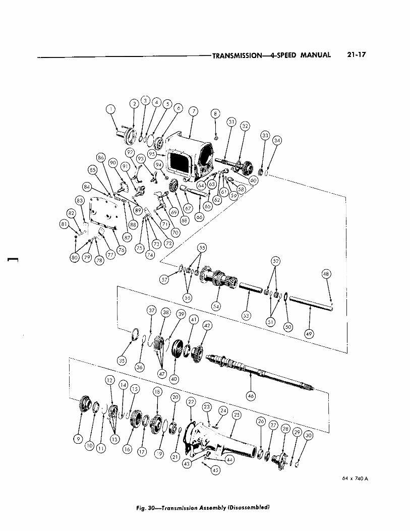
Fig. 30—Transmission Assembly (Disassembled)
21-18 TRANSMISSION—4-SPEED MANUAL
1. Bear ing Reta iner
2 . Bear ing Reta iner G a s k e t
3 . Bear ing Retainer O i l S e a l
4 . S n a p Ring, Bear ing ( Inner)
5 . S n a p Ring, Bear ing (Outer )
6. Pinion Bear ing
7. Transmission C a s e
8. F i l ler Plug
9 . G e a r , 2nd Speed
10. Stop Ring
11. Shift Plate Spr ings
12. C lutch G e a r
13. Shift Plates (3)
14. Shift Plate Spr ing
15. S n a p Ring
16. 1st a n d 2nd Clutch S leeve G e a r
17. Stop Ring
18. 1st S p e e d G e a r
19. Bear ing Retaining Ring
2 0 . C e n t e r Bear ing
2 1 . S n a p Ring
2 2 . G a s k e t , C a s e to Extension Housing
2 3 . Lockwasher
24 . Bolt
25 . Extension Housing
26 . Mainshaft Rear Bear ing
27 . Rear Bear ing O i l S e a l
28 . Compan ion F lange
2 9 . W a s h e r
3 0 . Nut
3 1 . Main Drive Pinion
3 2 . O i l S l inger
3 3 . N e e d l e Bear ing Rollers
34 . S n a p Ring
3 5 . Stop Ring
3 6 . S n a p Ring
37 . Shift Plate Spr ing
38 . Clutch G e a r
3 9 . Shift Plate Spr ing
4 0 . Clutch S leeve
4 1 . Stop Ring
4 2 . 3 r d S p e e d G e a r
4 3 . Speedometer Drive Pinion
44 . Speedometer Drive C l i p
45 . Speedometer Drive Pinion S e a l
46 . Mainshaf t (Output)
4 7 . Shift Plates (3)
48 . Woodruff Key
49 . Countershaf t
5 0 . Thrustwasher, G e a r (1)
5 1 . Thrustwasher , N e e d l e Roller
Bear ing
52 . Need le Bear ing Rollers
53 . Bear ing S p a c e r
54 . Countershaft G e a r (Cluster)
5 5 . Need le Bear ing Rollers
56. Thrustwasher , N e e d l e Roller
Bear ing
5 7 . Thrustwasher, G e a r (1)
5 8 . Backup Light Switch
59 . Backup Light Switch G a s k e t
6 0 . Plug
61 . Retainer , Reverse Detent Bal l
Spr ing
6 2 . G a s k e t
6 3 . S p r i n g , Reverse Detent Bal l
6 4 . Ba l l , Reverse Detent
6 5 . Woodruff Key
66 . Reverse Sl ider G e a r Shaf t
6 7 . Bushing, Reverse S l ider G e a r
68 . G e a r , Reverse Sl ider
69 . Fork, Reverse Shifter
7 0 . Reverse Lever
7 1 . O i l S e a l , Reverse Lever Shaf t
7 2 . Reverse O p e r a t i n g Lever
7 3 . F la twasher
74 . Lockwasher
7 5 . Nut
7 6 . Gearsh i f t Control Housing
7 7 . 1st and 2nd O p e r a t i n g Lever
78 . F la twasher
7 9 . Lockwasher , Lever
8 0 . Nut , Lever
8 1 . Lockwasher , Lever
8 2 . F la twasher , Lever
8 3 . 3 rd and 4th O p e r a t i n g Lever
84 . Detent Bal l
85 . Detent Bal l Pin
8 6 . Detent Bal l S leeve
87 . Detent Bal l Spr ing
88 . Detent Bal l
89 . O i l S e a l (2)
90 . 3 rd a n d 4th Lever
9 1 . 1st and 2nd Lever
9 2 . 3rd and 4th S p e e d Fork
93 . 1st and 2nd S p e e d Fork
94 . Dra in Plug
9 5 . G a s k e t , Shift Control Housing
Legend for F igure 3 0
(1) Disconnect the gearshift control rods from the shift control levers (Fig. 28), and the transmission operating levers, by removing the spring retainer clips and the flatwashers.
(2) Remove the two gearshift control housing mounting bolts, then remove the gearshift control housing from the transmission extension housing or mounting bracket. Remove the gearshift control housing mounting bracket bolts and remove bracket.
(3) Remove the back-up light switch. (If so equipped.)
(4) Using holding tool C-3281 remove the companion flange attaching nut and washer, then slide the flange from the end of the mainshaft (output).
3 R D A N D 4 T H S P E E D L E V E R S IN 1 S T A N D 2 N D S P E E D G E A R S H I F T E R S H A F T N E U T R A L G E A R S H I F T E R S H A F T A N D D E T E N T P L A T E P O S I T I O N A N D D E T E N T P L A T E
Fig. 31—Transmission Shift Housing Assembly
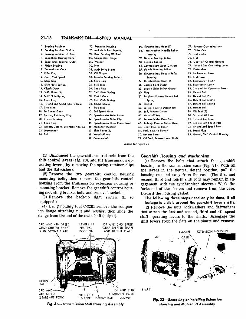
Gearshift Housing and Mechanism (1) Remove the bolts that attach the gearshift
housing to the transmission case (Fig. 31). With all the levers in the neutral detent position, pull the housing out and away from the case. (The first and second, third and fourth shift fork may remain in engagement with the synchronizer sleeves.) Work the forks out of the sleeves and remove from the case. Discard the housing gasket.
The following three steps need only be done, if oil leakage is visible around the gearshift lever shafts. (2) Remove the nuts, lockwashers and flatwashers
that attach the first and second, third and 4th speed shift operating levers to the shafts. Disengage the shift levers from the flats on the shafts and remove.
Fig. 32—Removing or Installing Extension Housing and Mainshaft Assembly
TRANSMISSION—4-SPEED MANUAL 21-19
1 S T A N D 2ND C L U T C H
S L E E V E G E A R (34 T E E T H )
S E C O N D S P E E D
G E A R ( 3 4 T E E T H )
M A I N S H A F T ^
1ST S P E E D G E A R ( 3 5 T E E T H )
E X T E N S I O N
H O U S I N G
/
S N A P
R I N G ' ^ ^ > >
S T O P R I N G j
3 R D A N D 4 T H C L U T C H S L E E V E 3 R D S P E E D G E A R ( 2 9 T E E T H )
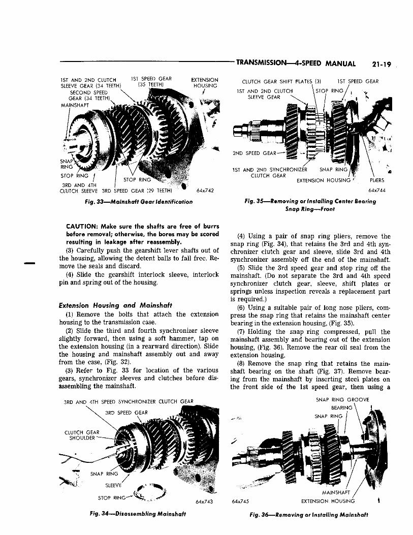
Fig. 33—Mainshaft Gear Identification
6 4 x 7 4 2
C L U T C H G E A R S H I F T P L A T E S (3)
1 S T A N D 2 N D C L U T C H
S L E E V E G E A R
1 S T S P E E D G E A R
2 N D S P E E D G E A R
1ST A N D 2 N D S Y N C H R O N I Z E R S N A P R I N G ,
C L U T C H G E A R E X T E N S I O N H O U S I N G
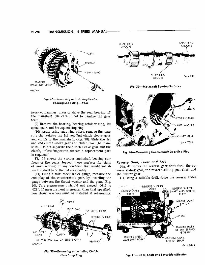
Fig. 3 5 — R e m o v i n g or Installing Center Bearing Snap Ring—Front
CAUTION: Make sure the shafts are free of burrs before removal; otherwise, the bores may be scored resulting in leakage after reassembly. (3) Carefully push the gearshift lever shafts out of
the housing, allowing the detent balls to fall free. Remove the seals and discard.
(4) Slide the gearshift interlock sleeve, interlock pin and spring out of the housing.
Extension Housing and Mainshaft (1) Remove the bolts that attach the extension
housing to the transmission case. (2) Slide the third and fourth synchronizer sleeve
slightly forward, then using a soft hammer, tap on the extension housing (in a rearward direction). Slide the housing and mainshaft assembly out and away from the case, (Fig. 32).
(3) Refer to Fig. 33 for location of the various gears, synchronizer sleeves and clutches before disassembling the mainshaft.
3 R D A N D 4 T H S P E E D S Y N C H R O N I Z E R C L U T C H G E A R
Fig. 34—Disassembling Mainshaft
(4) Using a pair of snap ring pliers, remove the snap ring (Fig. 34), that retains the 3rd and 4th synchronizer clutch gear and sleeve, slide 3rd and 4th synchronizer assembly off the end of the mainshaft.
(5) Slide the 3rd speed gear and stop ring off the mainshaft. (Do not separate the 3rd and 4th speed synchronizer clutch gear, sleeve, shift plates or springs unless inspection reveals a replacement part is required.)
(6) Using a suitable pair of long nose pliers, compress the snap ring that retains the mainshaft center bearing in the extension housing, (Fig. 35).
(7) Holding the snap ring compressed, pull the mainshaft assembly and bearing out of the extension housing, (Fig. 36). Remove the rear oil seal from the extension housing.
(8) Remove the snap ring that retains the main-shaft bearing on the shaft (Fig. 37). Remove bearing from the mainshaft by inserting steel plates on the front side of the 1st speed gear, then using a
S N A P R I N G G R O O V E
M A I N S H A F T
6 4 x 7 4 5 E X T E N S I O N H O U S I N G I
Fig. 36—Removing or Installing Mainshaft
21-20 TRANSMISSION—4-SPEED MANUAL-
P L I E R S
S E A R I N G
B E A R I N G
R E T A I N i N G R . N G
64x746
S N A P R I N G
F ig . 37—-Removing or Installing Center
Bearing Snap Ring—Rear
press or hammer, press or drive the rear bearing off the mainshaft. (Be careful not to damage the gear teeth.)
(9) Remove the bearing, bearing retainer ring, 1st speed gear, and first speed stop ring.
(10) Again using snap ring pliers, remove the snap ring that retains the 1st and 2nd clutch sleeve gear and clutch to the mainshaft, (Fig. 38). Slide the 1st and 2nd clutch sleeve gear and clutch from the main-shaft. (Do not separate the clutch sleeve gear and the clutch, unless inspection reveals a replacement part is required.)
Fig. 39 shows the various mainshaft bearing surfaces of the gears. Inspect these surfaces for signs of wear, scoring, or any condition that would not allow the shaft to be used at reassembly.
(11) Using a shim stock feeler gauge, measure the end play of the countershaft gear, by inserting the gauge between the thrust washer and the gear, (Fig. 40). This measurement should not exceed .0045 to .028". If measurement is greater than that specified, new thrust washers must be installed at reassembly.
S N A P R I N G
L I E R S
S T O P R I N G
/ 1 S T S P E E D G E A R
2 N D S P E E D G E A R
R E T A I N I N G R I N G
... /
C L U T C H * " \
1 S T A N D 2 N D C L U T C H S L E E V E G E A R
64x747A
J B E A R I N G
S N A P R I N G G R O O V E
S N A P R I N G G R O O V E
S N A P R I N G G R O O V E
6 4 x 7 4 8
Fig. 39—Mainshaft Bearing Surfaces
* ^ % V \ F E E L E R G A U G E
K * * ' \ > N T H R U S T W A S H E R
C O U N T E R S H A F T G E A R
6 4 x 7 5 0 A
Fig. 40—Measuring Countershaft Gear End Play
Reverse Gear, Lever and Fork Fig. 41 shows the reverse gear shift fork, the re
verse sliding gear, the reverse sliding gear shaft and the cluster gear.
(1) Using a suitable drift, drive the reverse slider
R E V E R S E G E A R S H A F T
R E V E R S E S L I D I N G
G E A R
R E V E R S E S P E E D G E A R S H I F T F O R K
R E V E R S E S H I F T E R * . S H A F T A N D D E T E N T
P L A T E
^ B A C K U P L I G H T IT* S W I T C H
P L U G
R E V E R S E L E V E R D E T E N T S P R I N G
R E T A I N E R
R E V E R S E G E A R S H I F T E R S H A F T
6 4 x 7 4 9 A
Fig. 38—Removing or Installing Clutch Gear Snap Ring Fig. 41—Gear, Shaft and Lever Identification
TRANSMISSION—4-SPEED MANUAL 21-21
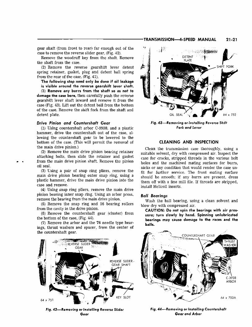
gear shaft (from front to rear) far enough out of the ease to remove the reverse slider gear, (Fig. 42).
Remove the woodruff key from the shaft. Remove the shaft from the case.
(2) Remove the reverse gearshift lever detent spring retainer, gasket, plug and detent ball spring from the rear of the case, (Fig. 41).
The following step need only be done if oil leakage is visible around the reverse gearshift lever shaft. (3) Remove any burrs from the shaft so as not to
damage the case bore, then carefully push the reverse gearshift lever shaft inward and remove it from the case (Fig. 43). Lift out the detent ball from the bottom of the case. Remove the shift fork from the shaft and detent plate.
Drive Pinion and Countershaft Gear (1) Using countershaft arbor C-3938, and a plastic
hammer, drive the countershaft out of the case, allowing the countershaft gear to be lowered to the bottom of the case. (This will permit the removal of the main drive pinion.)
(2) Remove the main drive pinion bearing retainer attaching bolts, then slide the retainer and gasket from the main drive pinion shaft. Remove the pinion oil seal.
(3) Using a pair of snap ring pliers, remove the main drive pinion bearing outer snap ring, using a plastic hammer, drive the main drive pinion into the case and remove.
(4) Using snap ring pliers, remove the main drive pinion bearing inner snap ring. Using an arbor press, remove the bearing from the main drive pinion.
(5) Remove the snap ring and 16 bearing rollers from the cavity in the drive pinion.
(6) Remove the countershaft gear (cluster) from the bottom of the case, (Fig. 44).
(7) Remove the arbor and the 76 needle type bearings, thrust washers and spacer, from the center of the countershaft gear.
F i g . 43—Removing or Installing Reverse Shift Fork and Lever
CLEANING AND INSPECTION
Clean the transmission case thoroughly, using a suitable solvent, dry with compressed air. Inspect the case for cracks, stripped threads in the various bolt holes and the machined mating surfaces for burrs, nicks or any condition that would render the case unfit for further service. The front mating surface should be smooth; if any burrs are present, dress them off with a fine mill file. If threads are stripped, install Helicoil inserts.
Ball Bearings Wash the ball bearing, using a clean solvent and
blow dry with compressed air. CAUTION: Do not spin the bearings with air pressure; turn slowly by hand. Spinning unlubricated bearings may cause damage to the races and the balls.
' •;- x " 5 3 A
Fig. 42—Removing or Installing Reverse Slider Gear
Fig. 44—Removing or Installing Countershaft Gear and Arbor
21-22 TRANSMISSION—4-SPEED MANUAL
Be sure the ball bearings are clean, then lubricate them with light grade engine oil. Inspect the bearings for roughness. This can best be determined by slowly turning the outer race by hand. Measure the fit of the bearings on their respective shafts.
Needle Type Bearing Rollers and Spacers Inspect all bearing rollers for flat spots or brinell-
ing. Inspect all bearing roller spacers for signs of wear or galling. Install new parts as required.
Gears Inspect the gear teeth on the synchronizer clutch
gears and stop rings. If there is evidence of chipping or excessively worn teeth, install new parts at reassembly. Be sure the clutch sleeve slides easily on the clutch gear. Inspect the countershaft gear and all sliding gear teeth for chipped or broken teeth, or showing signs of excessive wear. Small nicks or burrs must be stoned off.
Inspect the teeth on the main drive pinion. If excessively worn, broken or chipped, a new pinion should be installed.
Test the interlock sleeve and pin for free movement in the bore of the shift housing. Examine the detent balls for signs of brinelling. If the lever detents show signs of excessive wear to the extent of not locking in gear, install a new part. Inspect the shift forks for wear on the shanks and pads.
Synchronizer Stop Rings Inspect the stop rings for cracks at the corners of
the shift plate indexing slots. If the rings are cracked or show signs of extreme wear on the threaded bore, install new rings at reassembly.
Mainshaft Inspect the mainshaft gear and bearing mating sur
faces. If the gear contact surfaces show signs of galling or excessively worn, a new mainshaft should be installed.
Inspect the snap ring grooves for burred edges. If rough or burred, remove the condition using a fine file or crocus cloth. Inspect the synchronizer clutch gear teeth on the shaft for burrs.
ASSEMBLY
Countershaft Gear and Drive Pinion (1) Using heavy grease, coat the inside of the bore
of the gear at each end, then install the roller bearing spacer; centered. Insert arbor Tool C-3938, into the gear and through the spacer. Center the arbor.
(2) Coat the needle type roller bearings with heavy grease, then at each end of the gear, install 19 rollers, followed by a spacer ring and 19 more roller bearings and 1 spacer ring, (Fig. 30).
THRUST W A S H E R T A N G
C O U N T E R S H A F T G E A R
A R B O R " l - V \ t
STHRUST WASHER , A
T A N G 6 4 x 7 5 4
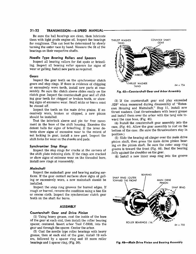
Fig. 4 5 — C o u n t e r s h a f t Gear and Arbor Assembly
(3) If the countershaft gear end play exceeded .028" when measured during disassembly of "Extension Housing and Mainshaft/' Step 11, install new thrust washers. Coat thrustwashers with heavy grease and install them over the arbor with the tang side toward the case boss, (Fig. 45).
(4) Install the countershaft gear assembly into the case, (Fig. 44). Allow the gear assembly to rest on the bottom of the case. (Be sure the thrustwashers stay in position.)
(5) Slide the bearing oil slinger over the main drive pinion shaft, then press the main drive pinion bearing on the pinion shaft. Be sure the outer snap ring groove is toward the front (Fig. 46). Seat the bearing fully against the shoulder on the gear.
(6) Install a new inner snap ring into the groove
BEARING S N A P RING (OUTER) TOWARD THE FRONT M A I N DRIVE
P IN ION
SNAP RING
4 ^ 7 $ $ , / ' * 7 ' X ,
ROLLER BEARINGS ( 1 6 ) " 64 x 755
Fig. 46—Main Drive Pinion and Bearing Assembly
TRANSMISSION—4-SPEED MANUAL 21-23
to retain the bearing. Be sure the snap ring is seated. (7) Place the pinion shaft in a vise (with soft jaws),
then install 16 bearing rollers in the cavity of the shaft. Coat the bearing rollers with heavy grease, then install the bearing retaining snap ring in its groove.
(8) Install the main drive pinion and bearing in the case and into position in the front bore. Tap lightly into place, using a plastic hammer. Install the outer snap ring in the bearing groove.
(9) Using Tool C-3789, install a new oil seal in the retainer bore. Install the main drive pinion bearing retainer and gasket. Install the attaching bolts and tighten to 35 foot-pounds torque.
(10) Start the countershaft in its bore at the rear of the case. Raise the countershaft gear until the teeth mesh with the main drive pinion gear. (Be sure the thrust washers remain in position on the ends of the arbor and the tangs aligned with the slots in the case.)
(11) Align the countershaft arbor with the bores in the case, then drive or press the countershaft into the gear. Install the woodruff key. Continue to press the shaft into the case until the end of the shaft is flush with the rear face of the case. Remove arbor Tool C-3938.
Reverse Gear, Lever and Fork The following step need only be done if the reverse
shaft was removed because of an oil leak. (1) Install a new oil seal on the reverse gearshift
lever shaft. Coat the lever shaft with multi-purpose grease, then carefully install the lever shaft into bore in the case, (Fig. 43). Install the reverse fork in the lever. Fill the recess next to the shaft with multipurpose grease, then install the operating lever, (Fig. 29). Install a flatwasher, lockwasher and nut. Tighten nut securely.
(2) Install the reverse shift detent ball and spring. Install the reverse detent ball spring retainer gasket and retainer. Tighten securely.
(3) Position the reverse slider gearshaft in position in the end of the case, and drive in far enough to position the reverse slider gear on the protruding end of the shaft with the shift slot toward the rear, (Fig. 42). At the same time, engage the slot with the reverse shift fork.
(4) With the reverse slider gear correctly positioned, drive the reverse gear into the case far enough to be able to install the woodruff key. Drive the shaft into position, flush with the end of the case (Fig. 42).
(5) Install the back-up light switch and gasket (if so equipped), and tighten securely.
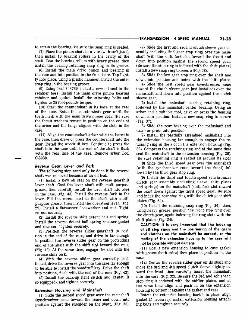
Extension Housing and Mainshaft (1) Slide the second speed gear over the mainshaft
(synchronizer cone toward the rear) and down into position against the shoulder on the shaft, (Fig. 38).
(2) Slide the first and second clutch sleeve gear assembly including 2nd gear stop ring) over the main-shaft (with the shift fork slot toward the front) and down into position against the second speed gear. (Be sure the stop ring is indexed with the shift plates.) Install a new snap ring to secure (Fig. 38).
(3) Slide the low gear stop ring over the shaft and down into position and index with the shift plates.
(4) Slide the first speed gear (synchronizer cone toward the clutch sleeve gear just installed) over the mainshaft and down into position against the clutch sleeve gear.
(5) Install the mainshaft bearing retaining ring, followed by the mainshaft center bearing. Using an arbor and a suitable tool, drive or press the bearing down into position. Install a new snap ring to secure (Fig. 37).
(6) Slide the rear bearing over the mainshaft and drive or press into position.
(7) Install the partially assembled mainshaft into the extension housing far enough to engage the retaining ring in the slot in the extension housing (Fig. 36). Compress the retaining ring and at the same time seat the mainshaft in the extension housing (Fig. 35). (Be sure retaining ring is seated all around its slot.)
(8) Slide the third speed gear over the mainshaft (with the synchronizer cone toward the front) followed by the third gear stop ring.
(9) Install the third and fourth speed synchronizer clutch gear assembly (including sleeve, shift plates and springs) on the mainshaft (shift fork slot toward the rear) down against the third speed gear. Be sure and index the rear stop ring with the clutch gear shift plates (Fig. 34).
(10) Install the retaining snap ring (Fig. 34), then, using heavy grease, position the front stop ring over the clutch gear, again indexing the ring slots with the shift plates (Fig. 34).
CAUTION: It is very important that the indexing of all stop rings and the positioning of the gears and clutches on the mainshaft be correct, or the mating of the extension housing to the case will not be possible without damage. (11) Coat a new extension housing to case gasket
with grease (both sides) then place in position on the case.
(12) Center the reverse slider gear on its shaft and move the 3rd and 4th speed clutch sleeve slightly toward the front, then carefully insert the mainshaft into the case, (Fig. 32). Be sure the 3rd and 4th speed stop ring is indexed with the shifter plates, and at the same time align and push in on the extension housing to bottom it against the gasket and case.
Rotate the extension housing back into place, align gasket if necessary, install extension housing attaching bolts and tighten securely.
21-24 TRANSMISSION—4-SPEED MANUAL
Gearshift Homing and Mechanism, The following 4 steps need only be done if the
gearshift housing was disassembled previously because of leaking seals.
(1) Slide the interlock sleeve into position in the housing, (Fig. 31). Install a new oil seal on each gear shifter shaft. Coat one of the shafts with multi-purpose grease, then install the operating lever, (Fig. 29). Install a flatwasher, lockwasher and nut. Tighten nut securely.
(2) Place a detent ball in the sleeve, followed by the spring and interlock pin. Coat the other gear shifter shaft with multi-purpose grease and start the shaft into the housing. Place remaining detent ball on the spring and compress ball and spring with a small screwdriver, then push shaft in until seated. Fill the recess next to the shaft with multi-purpose grease, then install the operating lever, flatwasher, lockwasher and nut. Tighten nut securely. Install the gearshift forks in the gear shifter shafts and position forks and shifter shafts in neutral position, (Fig. 31).
(3) Position the 1st and 2nd, 3rd and 4th clutch sleeve gears in the neutral position, then using a new gasket install the shift housing making sure the shift forks align with grooves in the clutch sleeve gears.
(4) With shift housing in place, install the retaining bolts finger tight, then shift transmission into reverse. Tighten the two end center alignment bolts first, then tighten the other retaining bolts. Test by shifting in and out of reverse several times making sure no interference occurs when shifting into reverse.
(5) Install the gearshift control assembly and connect the shift rods, (Fig. 28).
(6) Install the propeller shaft flange on end of the mainshaft. Install washer and nut, and tighten to 175 foot-pounds torque.
Installation Place a small amount of short fibre wheel bearing
lubricant around the inner end of the main drive pinion shaft pilot bushing in the flywheel and on the pinion bearing retainer release bearing sleeve area.
NOTE: Do not lubricate the end of the pinion shaft, the clutch disc splines or the clutch release levers. (1) Remove transmission from the repair stand.
Shift the transmission into reverse, then slide the assembly under the vehicle.
(2) With the shift lever side downward and using a suitable jack, raise the transmission until the drive pinion shaft is centered in the clutch housing bore.
(3) Roll the transmission slowly forward until the pinion shaft enters the clutch disc. Turn the pinion shaft until the splines are aligned, then work the transmission forward until seated against the clutch housing.
NOTE: Do not allow the transmission to "hang" after the pinion shaft has entered the clutch disc. (4) Rotate the transmission into position, install at
taching bolts and tighten to 50 foot-pounds torque. (5) Install the center crossmember and the four
long bolts, position the isolator assemblies over the bolts, install and tighten the retaining nuts to 50 foot-pounds torque. Make sure the extension housing insulator and/or spring is in place, install and tighten retaining bolts to 35 foot-pounds torque.
(6) Remove the engine support fixture and disengage the hooks from the holes in the frame side rails.
(7) Refer to Group 2 and reinstall the torsion bars and parts as outlined in "Torsion Bar Rubber Isola-tor."
(8) Install the speedometer pinion and cable. Reconnect the parking brake cable, propeller shaft, and back-up light switch leads.
(9) Reconnect the exhaust pipes (if removed). Tighten bolts securely.
(10) Fill the transmission with 7Vfe pints of Multipurpose Gear Oil SAE 140. If shift effort becomes extremely high during cold weather, Multi-purpose Gear Oil SAE 80 should be used. Automatic Transmission Fluid Type "A" Suffix "A" may also be used in extremely cold climates.
(11) Attach the gearshift lever to the stub lever on the shift housing, tighten the two bolts securely. Carefully slide the lower boot up over the two bolt heads.
(12) Slide the upper boot down the shift lever and secure in place with the screws. Install the console trim plate.
(13) Road test the vehicle to make sure the transmission shifts smoothly and operates quietly.
(14) If the shift linkage requires adjustment, refer to Page 15.
TORQUEFLITE TRANSMISSION (TORQUE CONVERTER) 21-25
PART 2
T O R Q U E F L I T E T R A N S M I S S I O N ( T O R Q U E C O N V E R T E R )
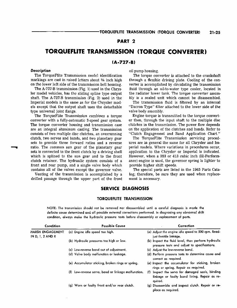
(A-727-B) Description
The TorqueFlite Transmission model identification markings are cast in raised letters about % inch high on the lower left side of the transmission bell housing.
The A-727-B transmission (Fig. 1) used in the Chrysler model vehicles, has the sliding spline type output shaft The A-727-B transmission (Fig. 2) used in the Imperial models is the same as for the Chrysler models except that the output shaft uses the detachable type universal joint flange.
The TorqueFlite Transmission combines a torque converter with a fully-automatic 3-speed gear system. The torque converter housing and transmission case are an integral aluminum casting. The transmission consists of two multiple disc clutches, an overrunning clutch, two servos and bands, and two planetary gear sets to provide three forward ratios and a reverse ratio. The common sun gear of the planetary gear sets is connected to the front clutch by a driving shell which is splined to the sun gear and to the front clutch retainer. The hydraulic system consists of a front and rear pump, and a single valve body which contains all of the valves except the governor valve.
Venting of the transmission is accomplished by a drilled passage through the upper part of the front
oil pump housing. The torque converter is attached to the crankshaft
through a flexible driving plate. Cooling of the converter is accomplished by circulating the transmission fluid through an oil-to-water type cooler, located in the radiator lower tank. The torque converter assembly is a sealed unit which cannot be disassembled.
The transmission fluid is filtered by an internal "Dacron Type" filter attached to the lower side of the valve body assembly.
Engine torque is transmitted to the torque converter then, through the input shaft to the multiple disc clutches in the transmission. The power flow depends on the application of the clutches and bands. Refer to "Clutch Engagement and Band Application Chart."
The TorqueFlite Transmission servicing procedures are in general the same for all Chrysler and Imperial models. Where variations in procedures occur, application to the Chrysler or Imperial is indicated. However, when a 383 or 413 cubic inch (Hi-Performance) engine is used, the governor spring is lighter to provide higher shift speeds.
The special parts are listed in the 1965 Parts Catalog; therefore, be sure they are used when replacement is necessary.
SERVICE DIAGNOSIS
TORQUEFLITE TRANSMISSION
NOTE: The transmission should not be removed nor disassembled until a careful diagnosis is made the definite cause determined and all possible external corrections performed. In diagnosing any abnormal shift condition, always make the hydraulic pressure tests before disassembly or replacement of parts.
Condit ion Possible Cause Correction
(a) Adjust the engine idle speed to 500 rpm. Readjust throttle linkage.
(b) Inspect the fluid level, then perform hydraulic pressure tests and adjust to specifications.
(c) Adjust the low-reverse band. (d) Perform pressure tests to determine cause and
correct as required. (e) Inspect the accumulator for sticking, broken
rings or spring. Repair as required. (f) Low-reverse servo, band or linkage malfunction, (f) Inspect the servo for damaged seals, binding
linkage or faulty band lining. Repair as required.
(g) Disassemble and inspect clutch. Repair or replace as required.
HARSH ENGAGEMENT (a) Engine idle speed too high. IN D, 1,2 AND R
(b) Hydraulic pressures too high or low.
(c) Low-reverse band out of adjustment. (d) Valve body malfunction or leakage.
(e) Accumulator sticking, broken rings or spring.
(g) Worn or faulty front and /o r rear clutch.
21-26 TORQUEFLITE TRANSMISSION (TORQUE CONVERTER)
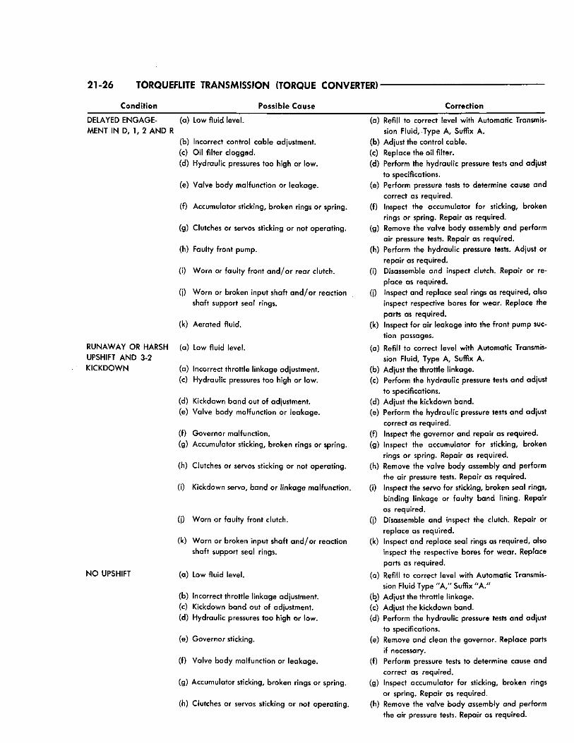
Condition Possible Cause Correction
DELAYED E N G A G E - (a) Low fluid level. MENT IN D, 1, 2 AND R
(b) Incorrect control cable adjustment. (c) Oil filter clogged. (d) Hydraulic pressures too high or low.
(e) Valve body malfunction or leakage.
(f) Accumulator sticking, broken rings or spring.
(g) Clutches or servos sticking or not operating.
(h) Faulty front pump.
(i) Worn or faulty front a n d / o r rear clutch.
(j) Worn or broken input shaft a n d / o r reaction shaft support seal rings.
(k) Aerated fluid.
RUNAWAY OR HARSH (a) Low fluid level. UPSHIFT AND 3-2
KICKDOWN (a) Incorrect throttle linkage adjustment. (c) Hydraulic pressures too high or low.
(d) Kickdown band out of adjustment. (e) Valve body malfunction or leakage.
(f) Governor malfunction.
(g) Accumulator sticking, broken rings or spring.
(h) Clutches or servos sticking or not operating.
(i) Kickdown servo, band or linkage malfunction.
(j) Worn or faulty front clutch.
(k) Worn or broken input shaft and /or reaction shaft support seal rings.
N O UPSHIFT (a) Low fluid level.
(b) Incorrect throttle linkage adjustment. (c) Kickdown band out of adjustment. (d) Hydraulic pressures too high or low.
(e) Governor sticking.
(f) Valve body malfunction or leakage.
(g) Accumulator sticking, broken rings or spring.
(h) Clutches or servos sticking or not operating.
(a) Refill to correct level with Automatic Transmission Fluid, Type A, Suffix A.
(b) Adjust the control cable. (c) Replace the oil filter. (d) Perform the hydraulic pressure tests and adjust
to specifications. (e) Perform pressure tests to determine cause and
correct as required. (f) Inspect the accumulator for sticking, broken
rings or spring. Repair as required. (g) Remove the valve body assembly and perform
air pressure tests. Repair as required. (h) Perform the hydraulic pressure tests. Adjust or
repair as required. (i) Disassemble and inspect clutch. Repair or re
place as required. (j) Inspect and replace seal rings as required, also
inspect respective bores for wear. Replace the parts as required.
(k) Inspect for air leakage into the front pump suction passages.
(a) Refill to correct level with Automatic Transmission Fluid, Type A, Suffix A.
(b) Adjust the throttle linkage. (c) Perform the hydraulic pressure tests and adjust
to specifications. (d) Adjust the kickdown band. (e) Perform the hydraulic pressure tests and adjust
correct as required. (f) Inspect the governor and repair as required. (g) Inspect the accumulator for sticking, broken
rings or spring. Repair as required. (h) Remove the valve body assembly and perform
the air pressure tests. Repair as required. (i) Inspect the servo for sticking, broken seal rings,
binding linkage or faulty band lining. Repair as required.
(j) Disassemble and inspect the clutch. Repair or replace as required,
(k) Inspect and replace seal rings as required, also inspect the respective bores for wear. Replace parts as required.
(a) Refill to correct level with Automatic Transmission Fluid Type "A ," Suffix "A ."
(b) Adjust the throttle linkage. (c) Adjust the kickdown band. (d) Perform the hydraulic pressure tests and adjust
to specifications. (e) Remove and clean the governor. Replace parts
if necessary. (f) Perform pressure tests to determine cause and
correct as required. (g) Inspect accumulator for sticking, broken rings
or spring. Repair as required. (h) Remove the valve body assembly and perform
the air pressure tests. Repair as required.
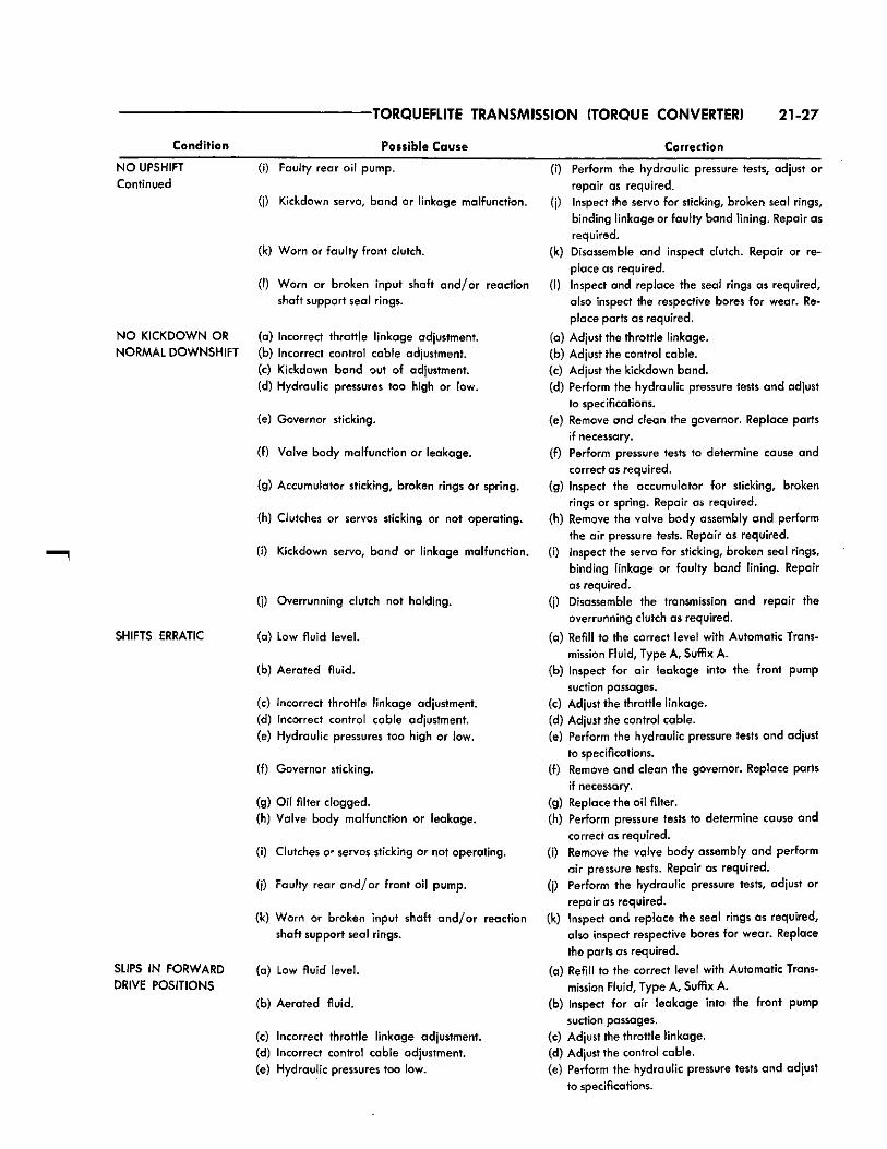
TORQUEFLITE TRANSMISSION (TORQUE CONVERTER) 21-27
Condition Possible Cause Correction
N O UPSHIFT Continued
(I) Faulty rear oil pump,
(j) Kickdown servo, band or linkage malfunction.
(k) Worn or faulty front clutch.
(I) Worn or broken input shaft and /or reaction shaft support seal rings.
N O KICKDOWN OR (a) Incorrect throttle linkage adjustment. NORMAL DOWNSHIFT (b) Incorrect control cable adjustment.
(c) Kickdown band out of adjustment.
(d) Hydraulic pressures too high or low.
(e) Governor sticking.
(f) Valve body malfunction or leakage.
(g) Accumulator sticking, broken rings or spring.
(h) Clutches or servos sticking or not operating.
(i) Kickdown servo, band or linkage malfunction.
SHIFTS ERRATIC
SLIPS IN FORWARD DRIVE POSITIONS
(j) Overrunning clutch not holding.
(a) Low fluid level.
(b) Aerated fluid.
(c) Incorrect throttle linkage adjustment. (d) Incorrect control cable adjustment.
(e) Hydraulic pressures too high or low.
(f) Governor sticking.
(g) Oil filter clogged.
(h) Valve body malfunction or leakage.
(i) Clutches o- servos sticking or not operating.
(j) Faulty rear and /o r front oil pump.
(k) Worn or broken input shaft and /or reaction shaft support seal rings.
(a) Low fluid level.
(b) Aerated fluid.
(c) Incorrect throttle linkage adjustment. (d) Incorrect control cable adjustment. (e) Hydraulic pressures too low.
(i) Perform the hydraulic pressure tests, adjust or repair as required,
(j) Inspect the servo for sticking, broken seal rings, binding linkage or faulty band lining. Repair as required.
(k) Disassemble and inspect clutch. Repair or replace as required.
(I) Inspect and replace the seal rings as required, also inspect the respective bores for wear. Replace parts as required.
(a) Adjust the throttle linkage. (b) Adjust the control cable. (c) Adjust the kickdown band. (d) Perform the hydraulic pressure tests and adjust
to specifications. (e) Remove and clean the governor. Replace parts
if necessary. (f) Perform pressure tests to determine cause and
correct as required. (g) Inspect the accumulator for sticking, broken
rings or spring. Repair as required. (h) Remove the valve body assembly and perform
the air pressure tests. Repair as required. (i) Inspect the servo for sticking, broken seal rings,
binding linkage or faulty band lining. Repair as required.
(j) Disassemble the transmission and repair the overrunning clutch as required.
(a) Refill to the correct level with Automatic Transmission Fluid, Type A, Suffix A.
(b) Inspect for air leakage into the front pump suction passages.
(c) Adjust the throttle linkage. (d) Adjust the control cable. (e) Perform the hydraulic pressure tests and adjust
to specifications. (f) Remove and clean the governor. Replace parts
if necessary. (g) Replace the oil filter. (h) Perform pressure tests to determine cause and
correct as required. (i) Remove the valve body assembly and perform
air pressure tests. Repair as required. (j) Perform the hydraulic pressure tests, adjust or
repair as required, (k) Inspect and replace the seal rings as required,
also inspect respective bores for wear. Replace the parts as required.
(a) Refill to the correct level with Automatic Transmission Fluid, Type A, Suffix A.
(b) Inspect for air leakage into the front pump suction passages.
(c) Adjust the throttle linkage. (d) Adjust the control cable. (e) Perform the hydraulic pressure tests and adjust
to specifications.
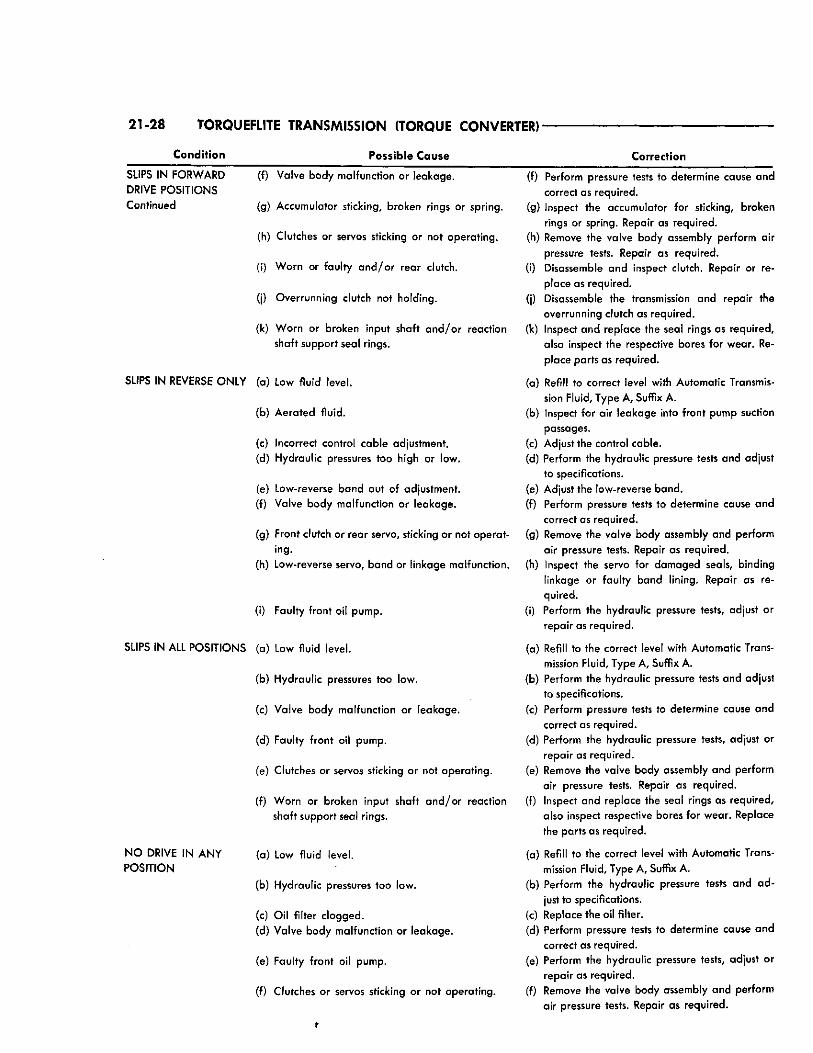
21-28 TORQUEFLITE TRANSMISSION (TORQUE CONVERTER)-
Condition Possible Cause Correction
SLIPS IN FORWARD DRIVE POSITIONS Continued
(f) Valve body malfunction or leakage.
(g) Accumulator sticking, broken rings or spring.
(h) Clutches or servos sticking or not operating.
(i) Worn or faulty a n d / o r rear clutch.
(j) Overrunning clutch not holding.
(k) Worn or broken input shaft and /or reaction shaft support seal rings.
SLIPS IN REVERSE ONLY (a) Low fluid level.
(b) Aerated fluid.
(c) Incorrect control cable adjustment. (d) Hydraulic pressures too high or low.
(e) Low-reverse band out of adjustment. (f) Valve body malfunction or leakage.
(g) Front clutch or rear servo, sticking or not operating.
(h) Low-reverse servo, band or linkage malfunction.
(i) Faulty front oil pump.
SLIPS IN ALL POSITIONS (a) Low fluid level.
(b) Hydraulic pressures too low.
(c) Valve body malfunction or leakage.
(d) Faulty front oil pump.
(e) Clutches or servos sticking or not operating.
(f) Worn or broken input shaft and /or reaction shaft support seal rings.
(a) Low fluid level.
(b) Hydraulic pressures too low.
(c) Oil filter clogged.
(d) Valve body malfunction or leakage.
(e) Faulty front oil pump.
(f) Clutches or servos sticking or not operating.
N O DRIVE IN ANY POSITION
(f) Perform pressure tests to determine cause and correct as required.
(g) Inspect the accumulator for sticking, broken rings or spring. Repair as required.
(h) Remove the valve body assembly perform air pressure tests. Repair as required.
(i) Disassemble and inspect clutch. Repair or replace as required.
(j) Disassemble the transmission and repair the overrunning clutch as required.
(k) Inspect and replace the seal rings as required, also inspect the respective bores for wear. Replace parts as required.
(a) Refill to correct level with Automatic Transmission Fluid, Type A, Suffix A.
(b) Inspect for air leakage into front pump suction passages.
(c) Adjust the control cable. (d) Perform the hydraulic pressure tests and adjust
to specifications. (e) Adjust the low-reverse band. (f) Perform pressure tests to determine cause and
correct as required. (g) Remove the valve body assembly and perform
air pressure tests. Repair as required. (h) Inspect the servo for damaged seals, binding
linkage or faulty band lining. Repair as required.
(i) Perform the hydraulic pressure tests, adjust or repair as required.
(a) Refill to the correct level with Automatic Transmission Fluid, Type A, Suffix A.
(b) Perform the hydraulic pressure tests and adjust to specifications.
(c) Perform pressure tests to determine cause and correct as required.
(d) Perform the hydraulic pressure tests, adjust or repair as required.
(e) Remove the valve body assembly and perform air pressure tests. Repair as required.
(f) Inspect and replace the seal rings as required, also inspect respective bores for wear. Replace the parts as required.
(a) Refill to the correct level with Automatic Transmission Fluid, Type A, Suffix A.
(b) Perform the hydraulic pressure tests and ad just to specifications.
(c) Replace the oil filter. (d) Perform pressure tests to determine cause and
correct as required. (e) Perform the hydraulic pressure tests, adjust or
repair as required. (f) Remove the valve body assembly and perform
air pressure tests. Repair as required.
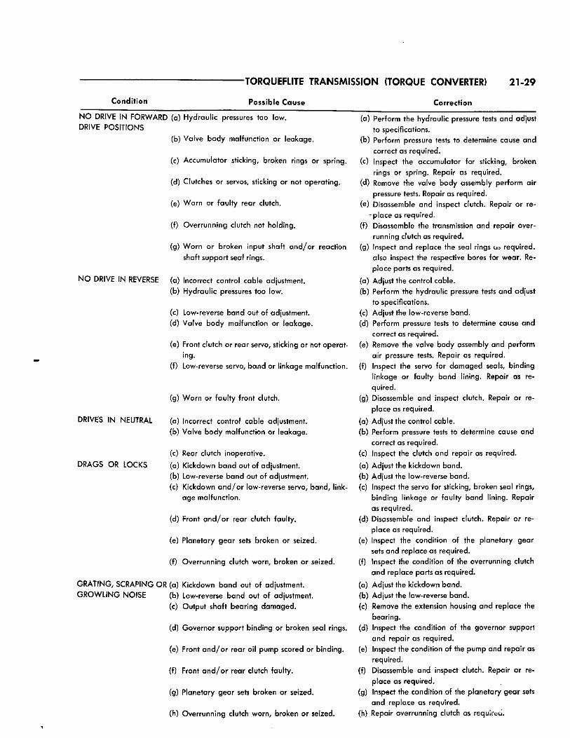
Condit ion
-TORQUEFLITE TRANSMISSION (TORQUE CONVERTER) 21-29
Possible C a u s e Correction
N O DRIVE IN FORWARD (a) Hydraulic pressures too low. DRIVE POSITIONS
(b) Valve body malfunction or leakage.
(c) Accumulator sticking, broken rings or spring.
(d) Clutches or servos, sticking or not operating.
(e) Worn or faulty rear clutch.
(f) Overrunning clutch not holding.
(g) Worn or broken input shaft and /or reaction shaft support seal rings.
N O DRIVE IN REVERSE (a) Incorrect control cable adjustment. (b) Hydraulic pressures too low.
(c) Low-reverse band out of adjustment. (d) Valve body malfunction or leakage.
(e) Front clutch or rear servo, sticking or not operating.
(f) Low-reverse servo, band or linkage malfunction.
(g) Worn or faulty front clutch.
(a) Incorrect control cable adjustment. (b) Valve body malfunction or leakage.
(c) Rear clutch inoperative.
(a) Kickdown band out of adjustment. (b) Low-reverse band out of adjustment. (c) Kickdown a n d / o r low-reverse servo, band, link
age malfunction.
(d) Front a n d / o r rear clutch faulty.
(e) Planetary gear sets broken or seized.
(f) Overrunning clutch worn, broken or seized.
GRATING, SCRAPING OR (a) Kickdown band out of adjustment. G R O W L I N G NOISE (b) Low-reverse band out of adjustment.
(c) Output shaft bearing damaged.
(d) Governor support binding or broken seal rings.
(e) Front a n d / o r rear oil pump scored or binding.
(f) Front a n d / o r rear clutch faulty.
(g) Planetary gear sets broken or seized.
(h) Overrunning clutch worn, broken or seized.
DRIVES IN NEUTRAL
DRAGS OR LOCKS
(a) Perform the hydraulic pressure tests and adjust to specifications.
(b) Perform pressure tests to determine cause and correct as required.
(c) Inspect the accumulator for sticking, broken rings or spring. Repair as required.
(d) Remove the valve body assembly perform air pressure tests. Repair as required.
(e) Disassemble and inspect clutch. Repair or re-- place as required.
(f) Disassemble the transmission and repair overrunning clutch as required.
(g) Inspect and replace the seal rings «J» required, also inspect the respective bores for wear. Replace parts as required.
(a) Adjust the control cable. (b) Perform the hydraulic pressure tests and adjust
to specifications. (c) Adjust the low-reverse band. (d) Perform pressure tests to determine cause and
correct as required. (e) Remove the valve body assembly and perform
air pressure tests. Repair as required. (f) Inspect the servo for damaged seals, binding
linkage or faulty band lining. Repair as required.
(g) Disassemble and inspect clutch. Repair or replace as required.
(a) Adjust the control cable. (b) Perform pressure tests to determine cause and
correct as required. (c) Inspect the clutch and repair as required.
(a) Adjust the kickdown band. (b) Adjust the low-reverse band. (c) Inspect the servo for sticking, broken seal rings,
binding linkage or faulty band lining. Repair as required.
(d) Disassemble and inspect clutch. Repair or replace as required.
(e) Inspect the condition of the planetary gear sets and replace as required.
(f) Inspect the condition of the overrunning clutch and replace parts as required.
(a) Adjust the kickdown band. (b) Adjust the low-reverse band. (c) Remove the extension housing and replace the
bearing. (d) Inspect the condition of the governor support
and repair as required. (e) Inspect the condition of the pump and repair as
required. (f) Disassemble and inspect clutch. Repair or re
place as required. (g) Inspect the condition of the planetary gear sets
and replace as required. (h) Repair overrunning clutch as required. .
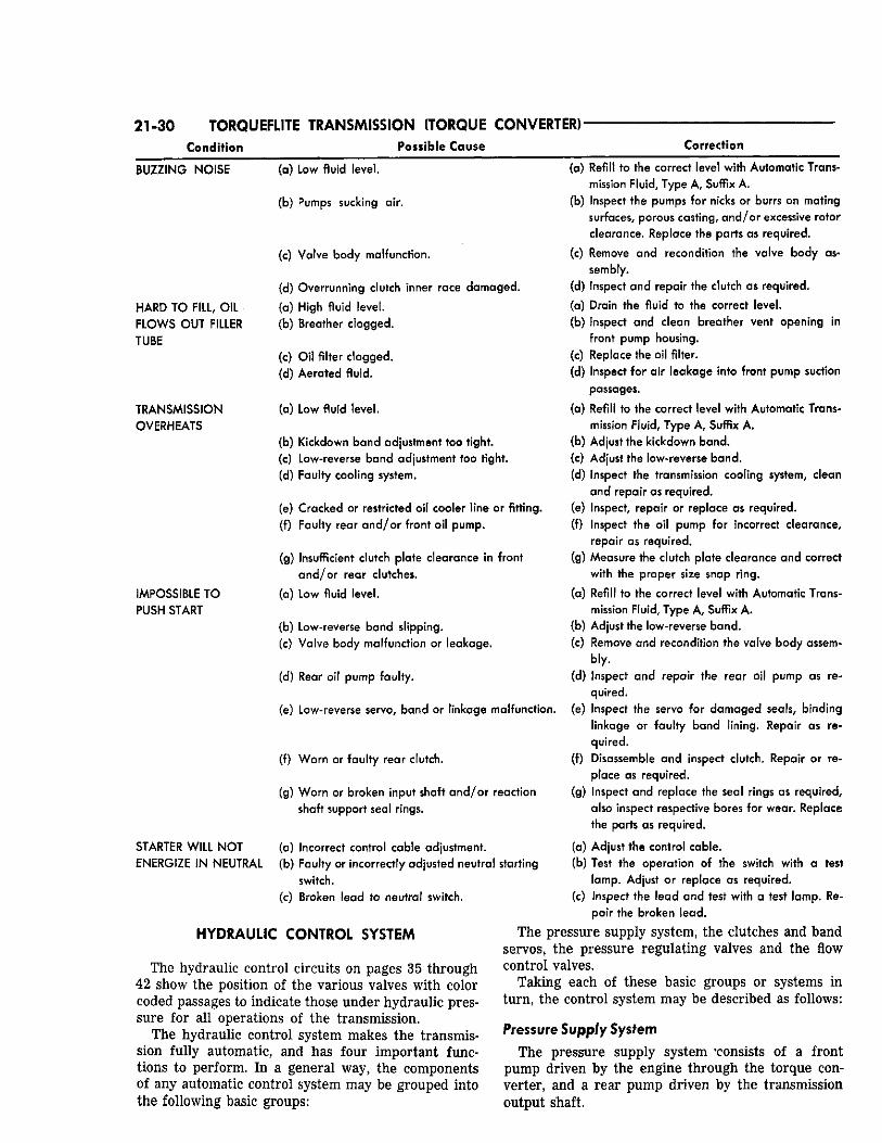
21-30 TORQUEFLITE TRANSMISSION {TORQUE CONVERTER)-Condition Possible Cause Correction
BUZZING NOISE
HARD TO FILL, OIL FLOWS OUT FILLER TUBE
TRANSMISSION OVERHEATS
IMPOSSIBLE TO PUSH START
STARTER WILL NOT ENERGIZE IN NEUTRAL
(a) Low fluid level.
(b) Pumps sucking air.
(c) Valve body malfunction.
(d) Overrunning clutch inner race damaged.
(a) High fluid level. (b) Breather clogged.
(c) Oil filter clogged. (d) Aerated fluid.
(a) Low fluid level.
(b) Kickdown band adjustment too tight. (c) Low-reverse band adjustment too tight. (d) Faulty cooling system.
(e) Cracked or restricted oil cooler line or fitting. (f) Faulty rear and /or front oil pump.
(g) Insufficient clutch plate clearance in front and /or rear clutches.
(a) Low fluid level.
(b) Low-reverse band slipping.
(c) Valve body malfunction or leakage.
(d) Rear oil pump faulty.
(e) Low-reverse servo, band or linkage malfunction.
(f) Worn or faulty rear clutch.
(g) Worn or broken input shaft a n d / o r reaction shaft support seal rings.
(a) Incorrect control cable adjustment. (b) Faulty or incorrectly adjusted neutral starting
switch. (c) Broken lead to neutral switch.
HYDRAULIC CONTROL SYSTEM
The hydraulic control circuits on pages 35 through 42 show the position of the various valves with color coded passages to indicate those under hydraulic pressure for all operations of the transmission.
The hydraulic control system makes the transmission fully automatic, and has four important functions to perform. In a general way, the components of any automatic control system may be grouped into the following basic groups:
(a) Refill to the correct level with Automatic Transmission Fluid, Type A , Suffix A.
(b) Inspect the pumps for nicks or burrs on mating surfaces, porous casting, and /or excessive rotor clearance. Replace the parts as required.
(c) Remove and recondition the valve body assembly.
(d) Inspect and repair the clutch as required.
(a) Drain the fluid to the correct level. (b) Inspect and clean breather vent opening in
front pump housing. (c) Replace the oil filter. (d) Inspect for air leakage into front pump suction
passages.
(a) Refill to the correct level with Automatic Transmission Fluid, Type A, Suffix A.
(b) Adjust the kickdown band. (c) Adjust the low-reverse band. (d) Inspect the transmission cooling system, clean
and repair as required. (e) Inspect, repair or replace as required. (f) Inspect the oil pump for incorrect clearance,
repair as required. (g) Measure the clutch plate clearance and correct
with the proper size snap ring.
(a) Refill to the correct level with Automatic Transmission Fluid, Type A, Suffix A .
(b) Adjust the low-reverse band. (c) Remove and recondition the valve body assem
bly. (d) Inspect and repair the rear oil pump as re
quired. (e) Inspect the servo for damaged seals, binding
linkage or faulty band lining. Repair as required.
(f) Disassemble and inspect clutch. Repair or replace as required.
(g) Inspect and replace the seal rings as required, also inspect respective bores for wear. Replace the parts as required.
(a) Adjust the control cable. (b) Test the operation of the switch with a test
lamp. Adjust or replace as required. (c) Inspect the lead and test with a test lamp. Re
pair the broken lead.
The pressure supply system, the clutches and band servos, the pressure regulating valves and the flow control valves.
Taking each of these basic groups or systems in turn, the control system may be described as follows:
Pressure Supply System The pressure supply system consists of a front
pump driven by the engine through the torque converter, and a rear pump driven by the transmission output shaft.
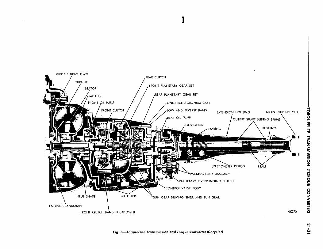
fig. I — T o r q u e F l i t e Transmission and Torque Converter (Chrysler)
to i
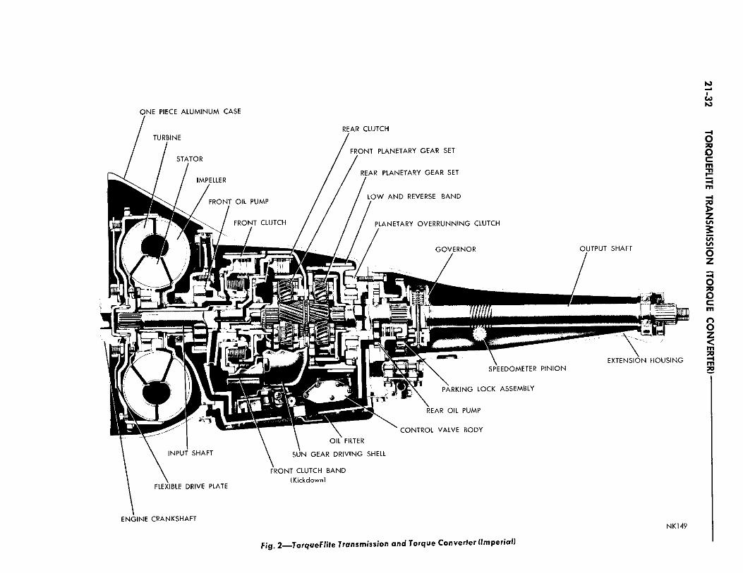
CO
O N E P I E C E A L U M I N U M C A S E
E N G I N E C R A N K S H A F T N K 1 4 9
F j g . 2 TorqueFlite Transmission and Torque Converter (Imperial}
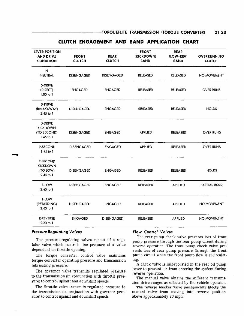
TORQUEFLITE TRANSMISSION (TORQUE CONVERTER) 21-33
C L U T C H E N G A G E M E N T A N D B A N D A P P L I C A T I O N C H A R T
LEVER POSITION A N D DRIVE C O N D I T I O N
FRONT CLUTCH
REAR CLUTCH
FRONT (K ICKDOWN)
BAND
REAR ( L O W - R E V )
BAND O V E R R U N N I N G
CLUTCH
N NEUTRAL DISENGAGED DISENGAGED RELEASED RELEASED NO MOVEMENT
D-DRIVE (DIRECT) 1.00 to 1
E N G A G E D E N G A G E D RELEASED RELEASED OVER RUNS
D-DRIVE (BREAKAWAY)
2.45 to 1 DISENGAGED ENGAGED RELEASED RELEASED HOLDS
D-DRIVE KICKDOWN
(TO SECOND) 1.45 to 1
DISENGAGED ENGAGED APPLIED RELEASED OVER RUNS
2-SECOND DISENGAGED E N G A G E D APPLIED RELEASED OVER RUNS 1.45 to 1
2-SECOND KICKDOWN
(TO LOW) D ISENGAGED E N G A G E D RELEASED RELEASED HOLDS 2 45 to 1
1-LOW DISENGAGED E N G A G E D RELEASED APPLIED PARTIAL HOLD 2.45 to 1
1-LOW (RETARDING) D ISENGAGED E N G A G E D RELEASED APPLIED N O MOVEMENT
2.45 to 1
R-REVERSE E N G A G E D DISENGAGED RELEASED APPLIED N O MOVEMENT 2.20 to 1
Pressure Regulating Valves
The pressure regulating valves consist of a regulator valve which controls line pressure at a value dependent on throttle opening.
The torque converter control valve maintains torque converter operating pressure and transmission lubricating pressure.
The governor valve transmits regulated pressure to the transmission (in conjunction with throttle pressure) to control upshift and downshift speeds.
The throttle valve transmits regulated pressure to the transmission (in conjunction with governor pressure) to control upshift and downshift speeds.
Flow Control Valves The rear pump check valve prevents loss of front
pump pressure through the rear pump circuit during reverse operation. The front pump check valve prevents loss of rear pump pressure through the front pump circuit when the front pump flow is recirculating.
A check valve is incorporated in the rear oil pump cover to prevent air from entering the system during reverse operation.
The manual valve obtains the different transmission drive ranges as selected by the vehicle operator.
The reverse blocker valve mechanically blocks the manual valve from moving into reverse position above approximately 20 mph.
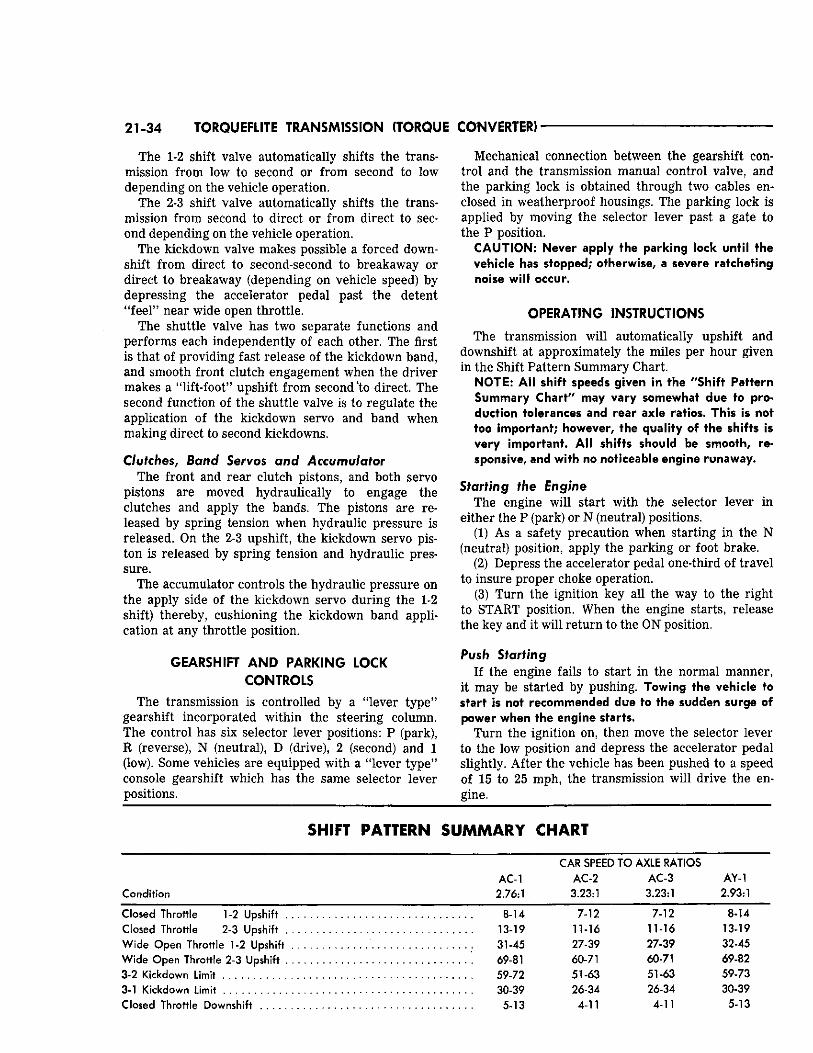
21-34 TORQUEFLITE TRANSMISSION (TORQUE CONVERTER)
The 1-2 shift valve automatically shifts the transmission from low to second or from second to low depending on the vehicle operation.
The 2-3 shift valve automatically shifts the transmission from second to direct or from direct to second depending on the vehicle operation.
The kickdown valve makes possible a forced downshift from direct to second-second to breakaway or direct to breakaway (depending on vehicle speed) by depressing the accelerator pedal past the detent "feel" near wide open throttle.
The shuttle valve has two separate functions and performs each independently of each other. The first is that of providing fast release of the kickdown band, and smooth front clutch engagement when the driver makes a "lift-foot" upshift from second 'to direct. The second function of the shuttle valve is to regulate the application of the kickdown servo and band when making direct to second kickdowns.
Clutches, Band Servos and Accumulator The front and rear clutch pistons, and both servo
pistons are moved hydraulically to engage the clutches and apply the bands. The pistons are released by spring tension when hydraulic pressure is released. On the 2-3 upshift, the kickdown servo piston is released by spring tension and hydraulic pressure.
The accumulator controls the hydraulic pressure on the apply side of the kickdown servo during the 1-2 shift) thereby, cushioning the kickdown band application at any throttle position.
GEARSHIFT AND PARKING LOCK CONTROLS
The transmission is controlled by a "lever type" gearshift incorporated within the steering column. The control has six selector lever positions: P (park), R (reverse), N (neutral), D (drive), 2 (second) and 1 (low). Some vehicles are equipped with a "lever type" console gearshift which has the same selector lever positions.
Mechanical connection between the gearshift control and the transmission manual control valve, and the parking lock is obtained through two cables enclosed in weatherproof housings. The parking lock is applied by moving the selector lever past a gate to the P position.
CAUTION: Never apply the parking lock until the vehicle has stopped; otherwise, a severe ratcheting noise will occur.
OPERATING INSTRUCTIONS
The transmission will automatically upshift and downshift at approximately the miles per hour given in the Shift Pattern Summary Chart.
NOTE: All shift speeds given in the "Shift Pattern Summary Chart" may vary somewhat due to production tolerances and rear axle ratios. This is not too important; however, the quality of the shifts is very important. All shifts should be smooth, responsive, and with no noticeable engine runaway.
Starting the Engine The engine will start with the selector lever in
either the P (park) or N (neutral) positions. (1) As a safety precaution when starting in the N
(neutral) position, apply the parking or foot brake. (2) Depress the accelerator pedal one-third of travel
to insure proper choke operation. (3) Turn the ignition key all the way to the right
to START position. When the engine starts, release the key and it will return to the ON position.
Push Starting If the engine fails to start in the normal manner,
it may be started by pushing. Towing the vehicle to start is not recommended due to the sudden surge of power when the engine starts.
Turn the ignition on, then move the selector lever to the low position and depress the accelerator pedal slightly. After the vehicle has been pushed to a speed of 15 to 25 mph, the transmission will drive the engine.
SHIFT PATTERN SUMMARY CHART
CAR SPEED TO AXLE RATIOS AC-1 AC-2 AC-3 AY-1
Condition 2.76:1 3.23:1 3.23:1 2.93:1
Closed Throttle 1-2 Upshift 8-14 7-12 7-12 8-14
Closed Throttle 2-3 Upshift 13-19 11-16 11 16 13-19
Wide Open Throttle 1 -2 Upshift 31-45 27-39 27-39 32-45
Wide Open Throttle 2-3 Upshift 69-81 60-71 60-71 69-82 3-2 Kickdown Limit 59-72 51-63 51-63 59-73
30-39 26-34 26-34 30-39
5-13 4-11 4-11 5-13
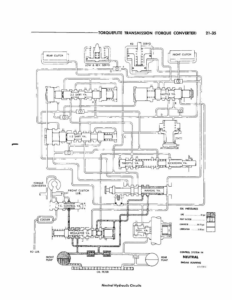
-TORQUEFLITE TRANSMISSION (TORQUE CONVERTER) 21-35
T O LUB. CONTROL SYSTEM IN
NEUTRAL ENGINE RUNNING
62x230C
OIL FILTER
Neutral Hydraulic Circuits
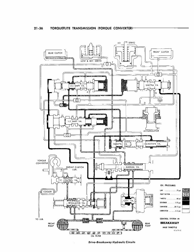
21-36 TORQUEFLITE TRANSMISSION (TORQUE CONVERTER)-
REAR C L U T C H
o
KD
o o
o
7 \ . r~ L O W & R E V . S E R V O
-CM
S E R V O
o o
=k l
F R O N T C L U T C H
2-3 SHIFT V A .
J Z L *4
1-2 SHIFT V A .
i 1—\ 1—1 r i T h o o Q o q
jo o o o q
to o o o q
X
fo o o o o q
SHUTTLE V A .
F R O N T C L U T C H [ J ) " ^ LUB.
T . C . C C O N T R O L V A .
rrrj C O O L E R fe^
^ 1
A C C U M U L A T O R
} o o o o o o o_o_oq -— v __r
THROTTLE V A . f ' 5 6 5 o o C OOP K I C K D O W N V A .
_ k • *
M A N U A L V A .
o 9 o 9<T
fo o o o o
r
TO LUB.
FRONT PUMP
Do o o / i o o o r . o o o o o ol_-
REAR PUMP
OIL PRESSURES
LINE 75 psi
PUMP SUCTION
THROTTLE . 4 0 psi
GOVERNOR 0-75 psi
CONVERTER 30 -75 psi
LUBRICATION 5-30 psi
CONTROL SYSTEM IN
BREAKAWAY HALF THROTTLE
62x231 C
OIL FILTER
Drive-Breakaway Hydraulic Circuits
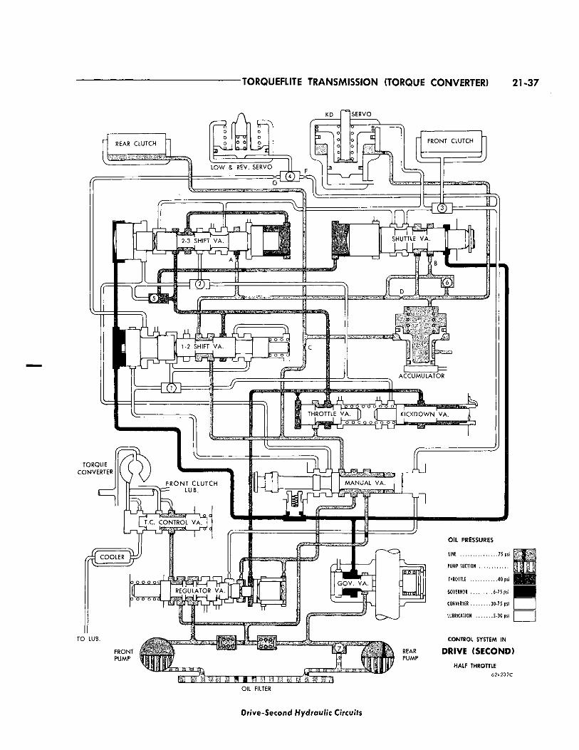
•TORQUEFLITE TRANSMISSION (TORQUE CONVERTER) 21-37
REAR CLUTCH
fF3 o o o
2 V £ L "
=7
KD
o o a E:
Z7~ L O W & REV. SERVO
~ G 2
SERVO
FRONT CLUTCH
2 o _ r X o 2-3 SHIFT V A .
C T L J ' L J i_n__f
r^i n . nJ) i p o o o r
X
1-2 SHIFT V A
T O R Q U E CONVERTER
5 o o 6
SHUTTLE V A .
F R O N T C L U T C H j V p ^ L U B .
K — ^ U3L
. C C O N T R O L V A . J
C O O L E R
a . H H H H 0 0 r=j
L A C C U M U L A T O R
^ ^ [ o o o o o o / THROTTLE V A . ) ( ' L- "J o o o o o o
K I C K D O W N V A .
M A N U A L V A .
o o o o o c
T O LUB.
\f1
G O V . V A
E E
O I L P R E S S U R E S
LINE 75 psi
PUMP SUCTION
THROTTLE 4 0 psi
GOVERNOR . . 6 - 7 5 psi
CONVERTER 30 -75 psi
LUBRICATION 5-30 psi
REAR PUMP
CONTROL SYSTEM IN
D R I V E ( S E C O N D )
HALF THROTTLE
62x232C
OIL FILTER
Dr /ve -Second Hydraulic Circuits
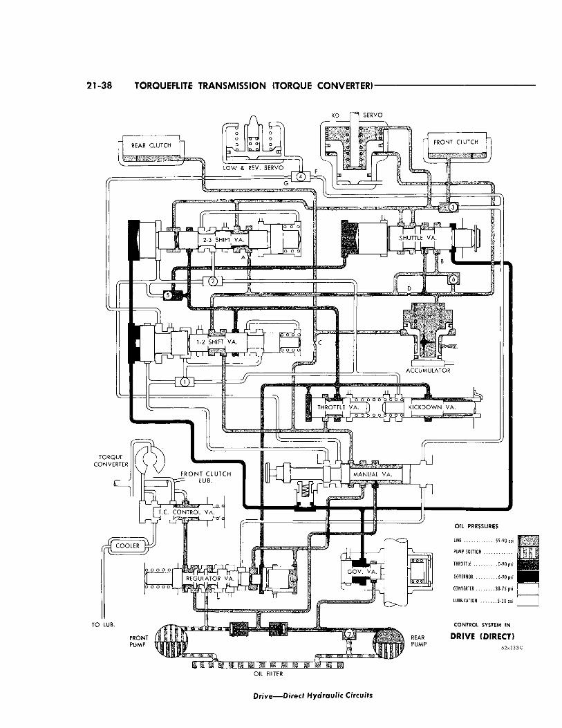
21-38 TORQUEFLITE TRANSMISSION (TORQUE CONVERTER)
Dr ive—Direct Hydraulic Circuits
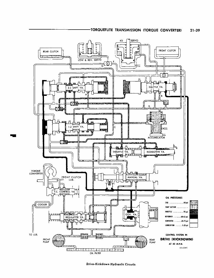
TORQUEFLITE TRANSMISSION (TORQUE CONVERTER) 21-39
REAR C L U T C H
KD
o o
rF1
L O W & REV. SERVO
o o
U=laJ
SERVO
FRONT CLUTCH
~ ~ i f , , /
zi- -rn..Jixjp_A_.n.^LJ p ° ° ° c
j 2-3 SHII *
JU nn
p Q o" Q -Q
SHUTTLE VA.
L J DC
,1 1-2 SHIFT VA. I
3/
F R O N T C L U T C H J N Y ^ LUB.
T.C. CONTROL VA.
4 C O O L E R fe^
~ ) f ~
re Lhri
ACCUMULATOR
\i I-
i
M A N U A L V A .
TO LUB.
YT1
HROTTLE VA. Y KICKDOWN VA. I I J k - j j ^ ^ k ^ S T , I
O I L P R E S S U R E S
LINE 90 psi
PUMP SUCTION
THROTTLE . 9 0 psi
GOVERNOR 6 0 - 6 5 psi
CONVERTER . 3 0 - 7 5 psi
LUBRICATION 5-30 psi
CONTROL SYSTEM IN
REAR DRIVE fKICKDOWN) P U M P AT 50 M.P.H.
6 2 x 2 3 4 C
OIL FILTER
Drive-Kickdown Hydraulic Circuits
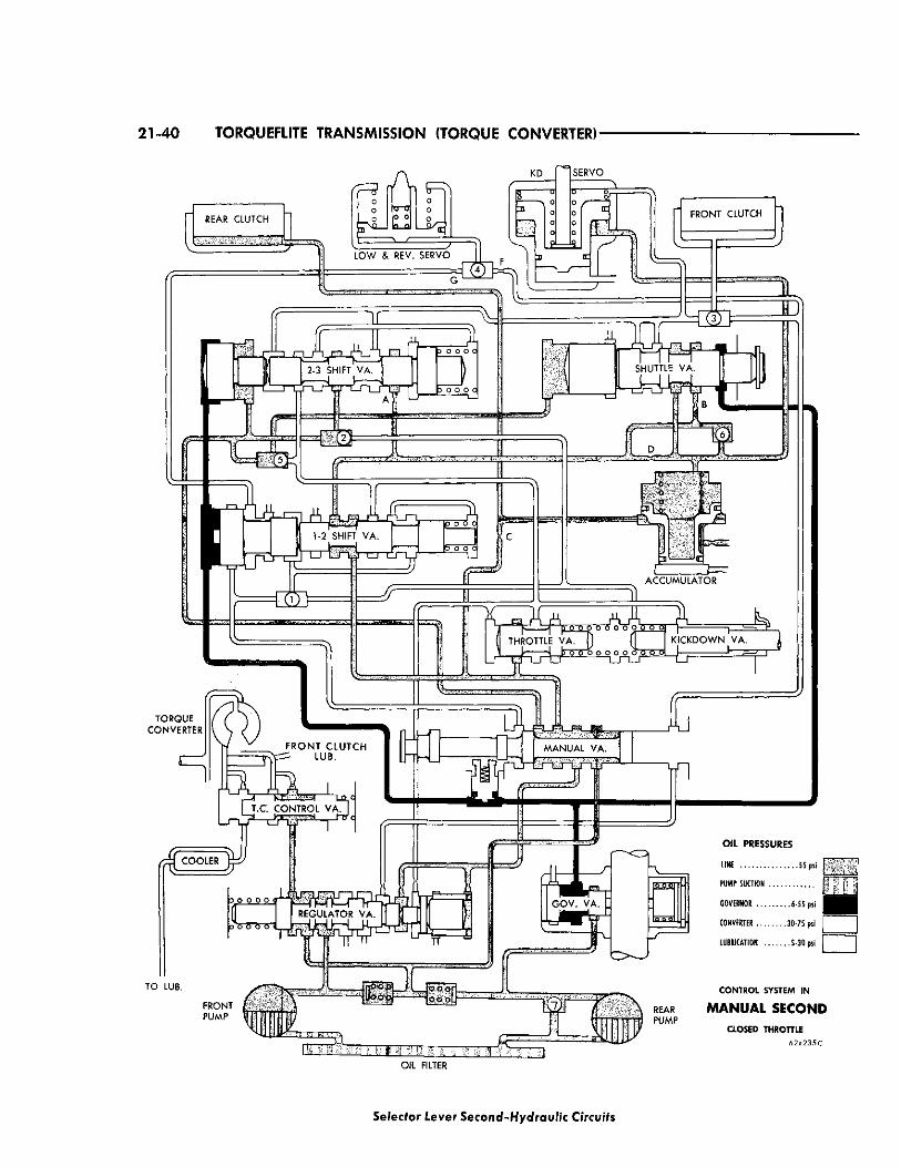
21-40 TORQUEFLITE TRANSMISSION (TORQUE CONVERTER)-
<7=S KD
REAR CLUTCH
1 T J L O W & REV. SERVO
SERVO
FRONT CLUTCH
2 A A 2-3 SHIFT VA.
" j _ j - T j r - L _ r i r r j i _ n _ r
I—I I D o o o o
1-2 SHIFT VA.
TJ-LriJr
i t m_
SHUTTLE VA.
F R O N T C L U T C H - L U B .
^ COOLER j ^ /
D O O O O
10 £ |
ACCUMULATOR
( THROTTLE VA. II (f K ICKDOWN VA. \ \ b ~ o ^ o o o o o B""5" 6 d 1
T - r u L / L J - L J — ^ L r J L
MANUAL VA.
TO LUB.
G O V . VA.
FRONT PUMP
j O O O o o o o
o o r o o l
O I L P R E S S U R E S
LINE . . 5 5 psi
PUMP SUCTION
GOVERNOR 6-55 psi
CONVERTER 30-75 psi | |
LUBRICATION 5-30 psi | |
CONTROL SYSTEM IN
REAR MANUAL SECOND PUMP
CLOSED THROTTLE 62x235C
OIL FILTER
Selector Lever Second-Hydraulic Circuits
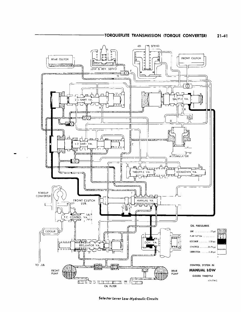
-TORQUEFLITE TRANSMISSION (TORQUE CONVERTER) 21-41
fr=3
REAR C L U T C H o o
KD
o o
r L O W & REV. S E R V O
S E R V O
"0 o o o F R O N T C L U T C H
n _ r u n 2-3 SHIFT V A .
JZL
Li
D O O O O 3,
D O O O O
X
TZT
1 r.HIFT V A .
iL v 1" izn__r
p o o o o o
6 o o o o o
SHUTTLE V A .
^ C O O L E R |p
X o" o L
31 A C C U M U L A T O R
( THROTTLE V A . ) ( 1 k \ p o o o o o o o o o o <
K I C K D O W N V A .
T O LUB.
OIL PRESSURES
LINE 55 psi
PUMP SUCTION
GOVERNOR . . 0 - 3 0 psi
CONVERTER 30-75 psi
LUBRICATION . . . . . . . 5-30 psi
CONTROL SYSTEM IN
MANUAL LOW CLOSED THROTTLE
6 2 x 2 3 6 C
OIL FILTER
Selector Lever Low-Hydraulic Circuits
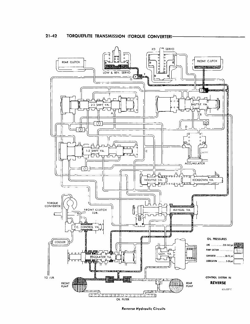
21-42 TORQUEFLITE TRANSMISSION (TORQUE CONVERTER)-
REAR CLUTCH
f F 3 o
3)
o o
KD
L O W & REV. SERVO
SERVO
r FRONT CLUTCH
1 HE
2-3 SHIFT V A
o o o o 3, I
p o o o
X
^ n m r1 ^ .^ i t — I *—•1 ^ | JT lo o o o o 1-2 SHIFT VA
-trd L J i_n_r
<0
o o o o
A i n
T
SHUTTLE VA.
I T.C. CONTROL V A . J
COOLER j^y
1-w
31 ACCUMULATOR
THROTTLE VA. ) ^ ' V 4 b o cTo OOP o o o o o o
KICKDOWN VA. 1 I-
TO LUB.
O I L P R E S S U R E S
LINE . . . . . . . . . . . 2 3 0 - 2 6 0 psi
PUMP SUCTION
CONVERTER . . 3 0 - 7 5 psi
LUBRICATION 5-30 psi
CONTROL SYSTEM IN
REYEftSE
6 2 x 2 3 7 C
OIL FILTER
Reverse Hydraulic Circuits
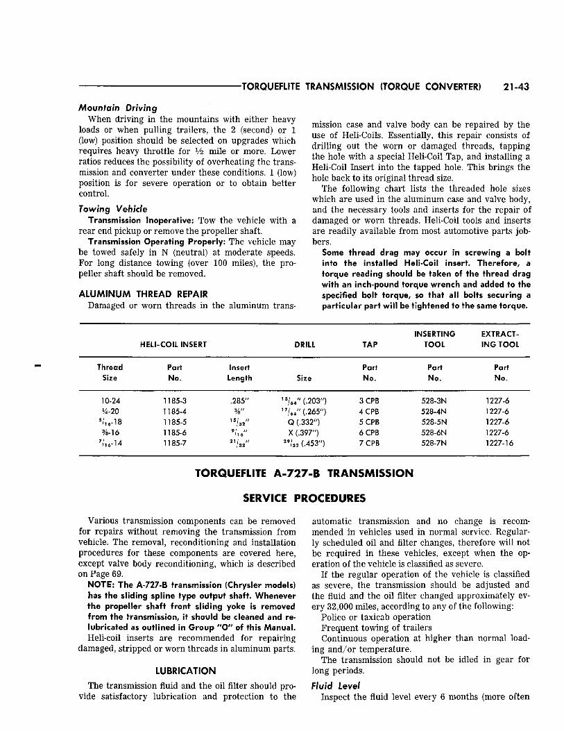
TORQUEFLITE TRANSMISSION (TORQUE CONVERTER) 21-43
Mountain Driving When driving in the mountains with either heavy
loads or when pulling trailers, the 2 (second) or 1 (low) position should be selected on upgrades which requires heavy throttle for Vi mile or more. Lower ratios reduces the possibility of overheating the transmission and converter under these conditions. 1 (low) position is for severe operation or to obtain better control. Towing Vehicle
Transmission Inoperative: Tow the vehicle with a rear end pickup or remove the propeller shaft.
Transmission Operating Properly: The vehicle may be towed safely in N (neutral) at moderate speeds. For long distance towing (over 100 miles), the propeller shaft should be removed.
ALUMINUM THREAD REPAIR Damaged or worn threads in the aluminum trans-
HELI -COIL
Thread Part Size No.
10-24 1185-3 VA-20 1185-4
5 / 1 6 - 1 8 1185-5 %-16 1185-6
7 / 1 6 - 1 4 1185-7
Various transmission components can be removed for repairs without removing the transmission from vehicle. The removal, reconditioning and installation procedures for these components are covered here, except valve body reconditioning, which is described on Page 69.
NOTE: The A-727-B transmission (Chrysler models) has the sliding spline type output shaft. Whenever the propeller shaft front sliding yoke is removed from the transmission, it should be cleaned and relubricated as outlined in Group "O" of this Manual. Heli-coil inserts are recommended for repairing
damaged, stripped or worn threads in aluminum parts.
LUBRICATION
The transmission fluid and the oil filter should provide satisfactory lubrication and protection to the
mission case and valve body can be repaired by the use of Heli-Coils. Essentially, this repair consists of drilling out the worn or damaged threads, tapping the hole with a special Heli-Coil Tap, and installing a Heli-Coil Insert into the tapped hole. This brings the hole back to its original thread size.
The following chart lists the threaded hole sizes which are used in the aluminum case and valve body, and the necessary tools and inserts for the repair of damaged or worn threads. Heli-Coil tools and inserts are readily available from most automotive parts jobbers.
Some thread drag may occur in screwing a bolt into the installed Heli-Coil insert. Therefore, a torque reading should be taken of the thread drag with an inch-pound torque wrench and added to the specified bolt torque, so that all bolts securing a particular part will be tightened to the same torque.
INSERTING E X T R A C T -T O O L I N G T O O L
Part Part No. No.
528-3N 1227-6 528-4N 1227-6 528-5N 1227-6 528-6N 1227-6 528-7N 1227-16
automatic transmission and no change is recommended in vehicles used in normal service. Regularly scheduled oil and filter changes, therefore will not be required in these vehicles, except when the operation of the vehicle is classified as severe.
If the regular operation of the vehicle is classified as severe, the transmission should be adjusted and the fluid and the oil filter changed approximately every 32,000 miles, according to any of the following:
Police or taxicab operation Frequent towing of trailers Continuous operation at higher than normal load
ing and/or temperature. The transmission should not be idled in gear for
long periods.
Fluid Level Inspect the fluid level every 6 months (more often
DRILL TAP
Insert Part Length Size No.
.285" 1 3 / 6 4 " ( . 2 0 3 " ) 3 C P B %" 1 7 / 6 4 " ( . 2 6 5 " ) 4 C P B
, 5 / 3 2" Q (.332") 5 C P B 9 / 1 6 " X (.397") 6 C P B
2 1 / 3 2 " 2 9 / 3 2 (.453") 7 C P B
TORQUEFLITE A-727-B TRANSMISSION
SERVICE PROCEDURES
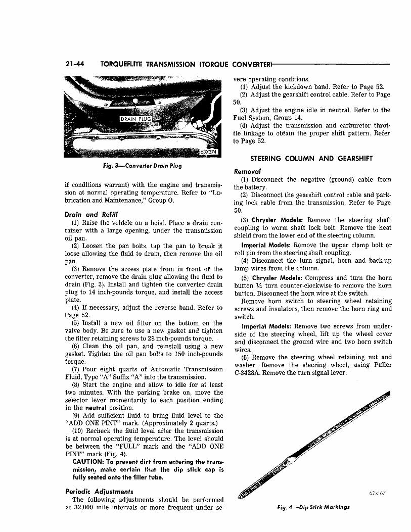
21-44 TORQUEFLITE TRANSMISSION {TORQUE CONVERTER}
Fig. 3—Converter Drain Plug
if conditions warrant) with the engine and transmission at normal operating temperature. Refer to "Lubrication and Maintenance/' Group 0.
Drain and Refill (1) Eaise the vehicle on a hoist. Place a drain con
tainer with a large opening, under the transmission oil pan.
(2) Loosen the pan bolts, tap the pan to break it loose allowing the fluid to drain, then remove the oil pan.
(3) Remove the access plate from in front of the converter, remove the drain plug allowing the fluid to drain (Fig. 3). Install and tighten the converter drain plug to 14 inch-pounds torque, and install the access plate.
(4) If necessary, adjust the reverse band. Refer to Page 52.
(5) Install a new oil filter on the bottom on the valve body. Be sure to use a new gasket and tighten the filter retaining screws to 28 inch-pounds torque.
(6) Clean the oil pan, and reinstall using a new gasket. Tighten the oil pan bolts to 150 inch-pounds torque.
(7) Pour eight quarts of Automatic Transmission Fluid, Type "A" Suffix "A" into the transmission.
(8) Start the engine and allow to idle for at least two minutes. With the parking brake on, move the selector lever momentarily to each position ending in the neutral position.
(9) Add sufficient fluid to bring fluid level to the "ADD ONE PINT" mark. (Approximately 2 quarts.)
(10) Recheck the fluid level after the transmission is at normal operating temperature. The level should be between the "FULL" mark and the "ADD ONE PINT" mark (Fig. 4).
CAUTION: To prevent dirt from entering the transmission, make certain that the dip stick cap is fully seated onto the filler tube.
Periodic Adjustments The following adjustments should be performed
at 32,000 mile intervals or more frequent under se
vere operating conditions. (1) Adjust the kickdown band. Refer to Page 52. (2) Adjust the gearshift control cable. Refer to Page
50. (3) Adjust the engine idle in neutral. Refer to the
Fuel System, Group 14. (4) Adjust the transmission and carburetor throt
tle linkage to obtain the proper shift pattern. Refer to Page 52.
STEERING COLUMN AND GEARSHIFT
Removal (1) Disconnect the negative (ground) cable from
the battery. (2) Disconnect the gearshift control cable and park
ing lock cable from the transmission. Refer to Page 50.
(3) Chrysler Models: Remove the steering shaft coupling to worm shaft lock bolt. Remove the heat shield from the lower end of the steering column.
Imperial Models: Remove the upper clamp bolt or roll pin from the steering shaft coupling.
(4) Disconnect the turn signal, horn and back-up lamp wires from the column.
(5) Chrysler Models: Compress and turn the horn button Vk turn counter-clockwise to remove the horn button. Disconnect the horn wire at the switch.
Remove horn switch to steering wheel retaining screws and insulators, then remove the horn ring and switch.
Imperial Models: Remove two screws from underside of the steering wheel, lift up the wheel cover and disconnect the ground wire and two horn switch wires.
(6) Remove the steering wheel retaining nut and washer. Remove the steering wheel, using Puller C-3428A. Remove the turn signal lever.
> T ~ r ~ 6 2 x 1 6 7 (. - *
Fig. 4—Dip Stick Markings
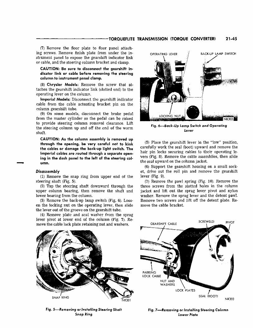
TORQUEFLITE TRANSMISSION (TORQUE CONVERTER) 21-45
(7) Remove the floor plate to floor panel attaching screws. Remove finish plate from under the instrument panel to expose the gearshift indicator link or cable, and the steering column bracket and clamp.
CAUTION; Be sure to disconnect the gearshift indicator link or cable before removing the steering column to instrument panel clamp.
(8) Chrysler Models: Remove the screw that attaches the gearshift indicator link (slotted end) to the operating lever on the column.
Imperial Models: Disconnect the gearshift indicator cable from the cable actuating bracket pin on the column gearshift tube.
(9) On some models, disconnect the brake pedal from the master cylinder so the pedal can be raised to provide steering column removal clearance. Lift the steering column up and off the end of the worm shaft.
C A U T I O N : A s the column assembly is removed up through the opening, be very careful not to kink the cables or damage the back-up light switch. T h e Imperial cables are routed through a separate opening in the dash panel to the left of the steering column.
Disassembly (1) Remove the snap ring from upper end of the
steering shaft (Fig. 5). (2) Tap the steering shaft downward through the
upper column bearing, then remove the shaft and lower bearing from the column.
(3) Remove the back-up lamp switch (Fig. 6). Loosen the locking nut on the operating lever, then slide the lever out of the groove on the gearshift tube.
(4) Remove plate and seal washer from the sprag lever pivot at lower end of the column (Fig. 7). Remove the cable lock plate retaining nut and washers.
S N A P R I N G . 1
N K 3 0 1
O P E R A T I N G L E V E R / B A C K - U P L A M P S W I T C H
\ - X
1 N _ K 3 0 2 ^
Fig. 6 — B a c k - U p Lamp Switch and Operating Lever
(5) Place the gearshift lever in the "low" position, carefully work the seal (boot) upward and remove the hair pin locks securing cables to their operating levers (Fig. 8). Remove the cable assemblies, then slide the seal upward on the column jacket.
(6) Support the gearshift housing on a small socket, drive out the roll pin and remove the gearshift lever (Fig. 9).
(7) Remove the pawl spring (Fig. 10). Remove the three screws from the slotted holes in the column jacket and lift out the sprag lever pivot and nylon washer. Remove the sprag lever and the detent pawl. Remove two screws and lift off the detent plate. Remove the cable bracket.
SEAL ( B O O T ) N K 3 0 3
Fig. 5—Removing or Installing Steering Shaft Snap Ring
Fig. 7—Removing or Installing Steering Column Lower Plate
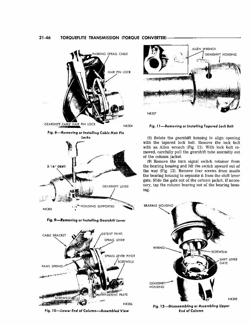
21-46 TORQUEfUTE TRANSMISSION (TORQUE CONVERTER)
P A R K I N G S P R A G C A B L E
H A I R P I N L O C K
G E A R S H I F T C A B L E H A I R P I N L O C K ! N K 3 0 4
Fig. &—Removing or Installing Cable Hair Pin Locks
3 / 1 6 " D R I F T
G E A R S H I F T L E V E R
/
? * A L L E N W R E N C H
f G E A R S H I F T H O U S I N G
V
N K 3 0 7
F i g . 7 1 — R e m o v i n g or Installing Tapered Lock Bolt
(8) Rotate the gearshift housing to align opening with the tapered lock bolt. Remove the lock bolt with an Allen wrench (Fig. 11). With lock bolt removed, carefully pull the gearshift tube assembly out of the column jacket.
(9) Remove the turn signal switch retainer from the bearing housing and lift the switch upward out of the way (Fig. 12). Remove four screws from inside the bearing housing to separate it from the shift lever gate.- Slide the gate out of the column jacket. If necessary, tap the column bearing out of the bearing housing.
N K 3 0 5 - H O U S I N G S U P P O R T E D B E A R I N G H O U S I N G
Fig. 9—Removing or Installing Gearshift Lever
C A B L E B R A C K E T
P A W L S P R I N G ^
S C R E W S ( 2 ) "
iHHHHi
D E T E N T P A W L
S P R A G L E V E R
S P R A G L E V E R P I V O T
' S C R E W S ( 3 )
.if*
M
- D E T E N T P L A T E
N K 3 0 6
F/g. 7 0 — l o w e r End &$ Column—Assembled View
W I R I N G
G E A R S H I F T
H O U S I N G
S C R E W S C 4 )
> S H I F T L E V E R
/ G A T E
N K 2 9 8
F i g . 7 2 — D i s a s s e m b l i n g or Assembling Upper End of Column
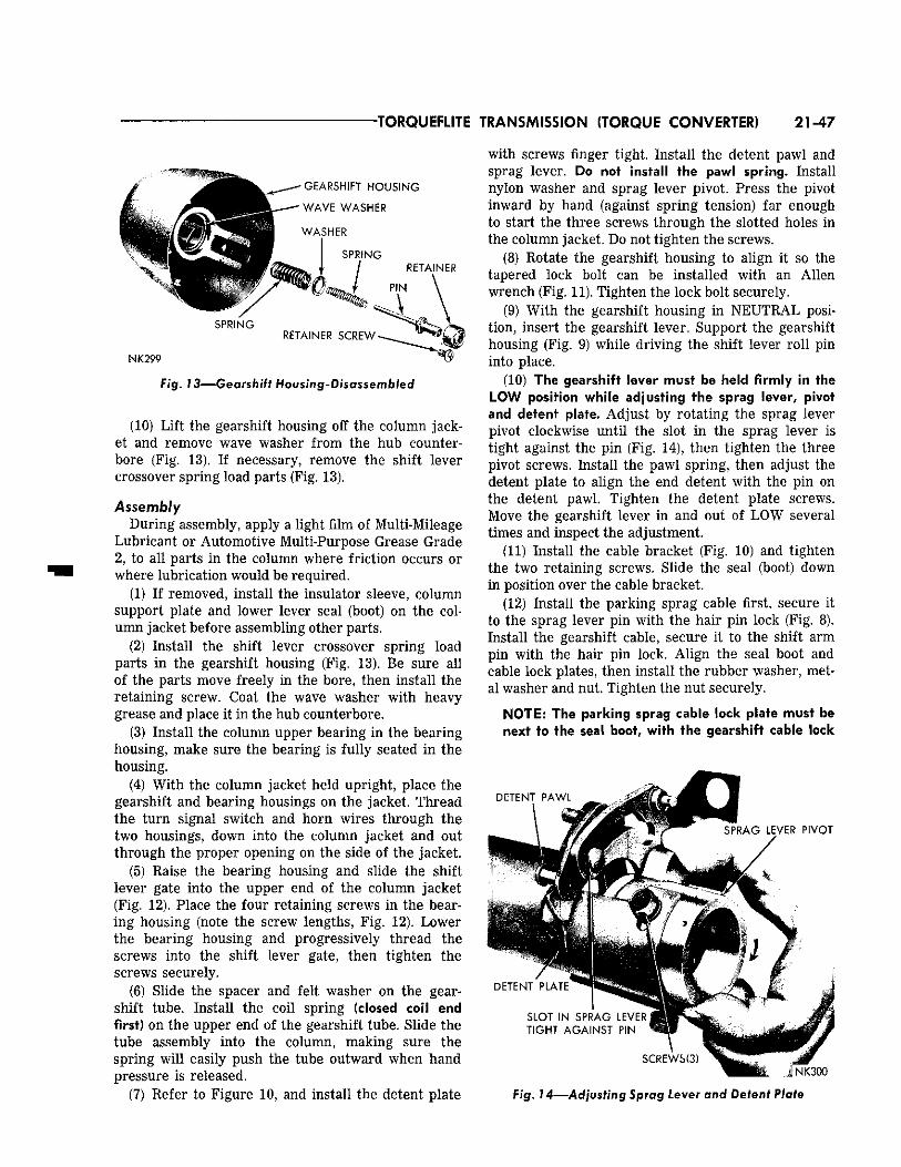
•TORQUEFLITE TRANSMISSION (TORQUE CONVERTER) 21-47
G E A R S H I F T H O U S I N G
W A V E W A S H E R
W A S H E R
S P R I N G
R E T A I N E R
N K 2 9 9
R E T A I N E R S C R E W
Fig. 73 — Gearsh i f t Housing-Disassembled
(10) Lift the gearshift housing off the column jacket and remove wave washer from the hub counter-bore (Fig. 13). If necessary, remove the shift lever crossover spring load parts (Fig. 13).
Assembly During assembly, apply a light film of Multi-Mileage
Lubricant or Automotive Multi-Purpose Grease Grade 2, to all parts in the column where friction occurs or where lubrication would be required.
(1) If removed, install the insulator sleeve, column support plate and lower lever seal (boot) on the column jacket before assembling other parts.
(2) Install the shift lever crossover spring load parts in the gearshift housing (Fig. 13). Be sure all of the parts move freely in the bore, then install the retaining screw. Coat the wave washer with heavy grease and place it in the hub counterbore.
(3) Install the column upper bearing in the bearing housing, make sure the bearing is fully seated in the housing.
(4) With the column jacket held upright, place the gearshift and bearing housings on the jacket. Thread the turn signal switch and horn wires through the two housings, down into the column jacket and out through the proper opening on the side of the jacket.
(5) Raise the bearing housing and slide the shift lever gate into the upper end of the column jacket (Fig. 12). Place the four retaining screws in the bearing housing (note the screw lengths, Fig. 12). Lower the bearing housing and progressively thread the screws into the shift lever gate, then tighten the screws securely.
(6) Slide the spacer and felt washer on the gearshift tube. Install the coil spring (closed coil end first) on the upper end of the gearshift tube. Slide the tube assembly into the column, making sure the spring will easily push the tube outward when hand pressure is released.
(7) Refer to Figure 10, and install the detent plate
with screws finger tight. Install the detent pawl and sprag lever. Do not install the pawl spring. Install nylon washer and sprag lever pivot. Press the pivot inward by hand (against spring tension) far enough to start the three screws through the slotted holes in the column jacket. Do not tighten the screws.
(8) Rotate the gearshift housing to align it so the tapered lock bolt can be installed with an Allen wrench (Fig. 11). Tighten the lock bolt securely.
(9) With the gearshift housing in NEUTRAL position, insert the gearshift lever. Support the gearshift housing (Fig. 9) while driving the shift lever roll pin into place.
(10) The gearshift lever must be held firmly in the LOW position while adjusting the sprag lever, pivot and detent plate. Adjust by rotating the sprag lever pivot clockwise until the slot in the sprag lever is tight against the pin (Fig. 14), then tighten the three pivot screws. Install the pawl spring, then adjust the detent plate to align the end detent with the pin on the detent pawl. Tighten the detent plate screws. Move the gearshift lever in and out of LOW several times and inspect the adjustment.
(11) Install the cable bracket (Fig. 10) and tighten the two retaining screws. Slide the seal (boot) down in position over the cable bracket.
(12) Install the parking sprag cable first, secure it to the sprag lever pin with the hair pin lock (Fig. 8). Install the gearshift cable, secure it to the shift arm pin with the hair pin lock. Align the seal boot and cable lock plates, then install the rubber washer, metal washer and nut. Tighten the nut securely.
NOTE: The parking sprag cable lock plate must be next to the seal boot, with the gearshift cable lock
D E T E N T P A W L
S P R A G L E V E R P I V O T
D E T E N T P L A T E
S L O T I N S P R A G L E V E R
T I G H T A G A I N S T P I N
• N K 3 0 0
Fig. 14—Adjusting Sprag Lever and Detent Plate
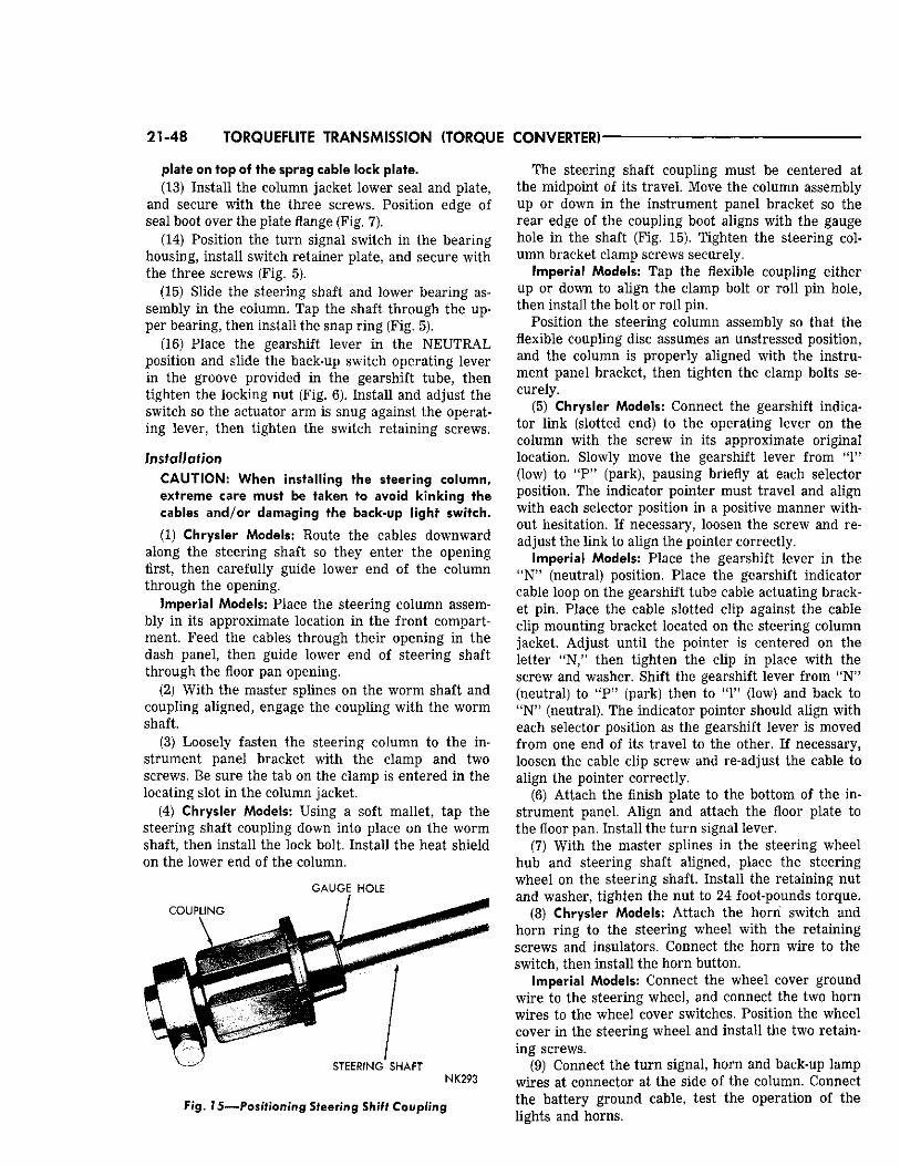
21-48 TORQUEFLITE TRANSMISSION (TORQUE CONVERTER)
plate on top of the sprag cable lock plate. (13) Install the column jacket lower seal and plate,
and secure with the three screws. Position edge of seal boot over the plate flange (Fig. 7).
(14) Position the turn signal switch in the bearing housing, install switch retainer plate, and secure with the three screws (Fig. 5).
(15) Slide the steering shaft and lower bearing assembly in the column. Tap the shaft through the upper bearing, then install the snap ring (Fig. 5).
(16) Place the gearshift lever in the NEUTRAL position and slide the back-up switch operating lever in the groove provided in the gearshift tube, then tighten the locking nut (Fig. 6). Install and adjust the switch so the actuator arm is snug against the operating lever, then tighten the switch retaining screws.
Installation CAUTION: When installing the steering column, extreme care must be taken to avoid kinking the cables and/or damaging the back-up light switch. (1) Chrysler Models: Route the cables downward
along the steering shaft so they enter the opening first, then carefully guide lower end of the column through the opening.
Imperial Models: Place the steering column assembly in its approximate location in the front compartment. Feed the cables through their opening in the dash panel, then guide lower end of steering shaft through the floor pan opening.
(2) With the master splines on the worm shaft and coupling aligned, engage the coupling with the worm shaft.
(3) Loosely fasten the steering column to the instrument panel bracket with the clamp and two screws. Be sure the tab on the clamp is entered in the locating slot in the column jacket.
(4) Chrysler Models: Using a soft mallet, tap the steering shaft coupling down into place on the worm shaft, then install the lock bolt. Install the heat shield on the lower end of the column.
GAUGE HOLE
F i g . 1 5 — P o s i t i o n i n g Steering Shift Coupling
The steering shaft coupling must be centered at the midpoint of its travel. Move the column assembly up or down in the instrument panel bracket so the rear edge of the coupling boot aligns with the gauge hole in the shaft (Fig. 15). Tighten the steering column bracket clamp screws securely.
Imperial Models: Tap the flexible coupling either up or down to align the clamp bolt or roll pin hole, then install the bolt or roll pin.
Position the steering column assembly so that the flexible coupling disc assumes an unstressed position, and the column is properly aligned with the instrument panel bracket, then tighten the clamp bolts securely.
(5) Chrysler Models: Connect the gearshift indicator link (slotted end) to the operating lever on the column with the screw in its approximate original location. Slowly move the gearshift lever from "1" (low) to "P" (park), pausing briefly at each selector position. The indicator pointer must travel and align with each selector position in a positive manner without hesitation. If necessary, loosen the screw and readjust the link to align the pointer correctly.
Imperial Models: Place the gearshift lever in the "N" (neutral) position. Place the gearshift indicator cable loop on the gearshift tube cable actuating bracket pin. Place the cable slotted clip against the cable clip mounting bracket located on the steering column jacket. Adjust until the pointer is centered on the letter "N," then tighten the clip in place with the screw and washer. Shift the gearshift lever from "N" (neutral) to "P" (park) then to "1" (low) and back to " N " (neutral). The indicator pointer should align with each selector position as the gearshift lever is moved from one end of its travel to the other. If necessary, loosen the cable clip screw and re-adjust the cable to align the pointer correctly.
(6) Attach the finish plate to the bottom of the instrument panel. Align and attach the floor plate to the floor pan. Install the turn signal lever.
(7) With the master splines in the steering wheel hub and steering shaft aligned, place the steering wheel on the steering shaft. Install the retaining nut and washer, tighten the nut to 24 foot-pounds torque.
(8) Chrysler Models: Attach the horn switch and horn ring to the steering wheel with the retaining screws and insulators. Connect the horn wire to the switch, then install the horn button.
Imperial Models: Connect the wheel cover ground wire to the steering wheel, and connect the two horn wires to the wheel cover switches. Position the wheel cover in the steering wheel and install the two retaining screws.
(9) Connect the turn signal, horn and back-up lamp wires at connector at the side of the column. Connect the battery ground cable, test the operation of the lights and horns.
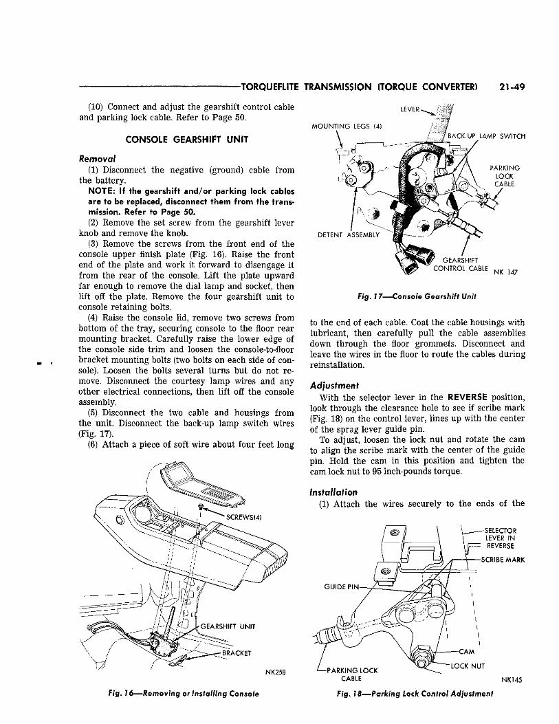
TORQUEFLITE TRANSMISSION (TORQUE CONVERTER) 21-49
(10) Connect and adjust the gearshift control cable and parking lock cable. Refer to Page 50.
CONSOLE GEARSHIFT UNIT
Removal (1) Disconnect the negative (ground) cable from
the battery. NOTE: If the gearshift and/or parking lock cables are to be replaced, disconnect them from the transmission. Refer to Page 50. (2) Remove the set screw from the gearshift lever
knob and remove the knob. (3) Remove the screws from the front end of the
console upper finish plate (Fig. 16). Raise the front end of the plate and work it forward to disengage it from the rear of the console. Lift the plate upward far enough to remove the dial lamp and socket, then lift off the plate. Remove the four gearshift unit to console retaining bolts.
(4) Raise the console lid, remove two screws from bottom of the tray, securing console to the floor rear mounting bracket. Carefully raise the lower edge of the console side trim and loosen the console-to-floor bracket mounting bolts (two bolts on each side of console). Loosen the bolts several turns but do not remove. Disconnect the courtesy lamp wires and any other electrical connections, then lift off the console assembly.
(5) Disconnect the two cable and housings from the unit. Disconnect the back-up lamp switch wires (Fig. 17).
(6) Attach a piece of soft wire about four feet long
L E V E R
B R A C K E T
N K 2 5 8
M O U N T I N G L E G S (4)
/ B A C K - U P ^ L A M P S W I T C H
D E T E N T A S S E M B L Y
' ? \ § / G E A R S H I F T C O N T R O L C A B L E
N K 1 4 7
Fig. 17—Console Gearshift Unit
to the end of each cable. Coat the cable housings with lubricant, then carefully pull the cable assemblies down through the floor grommets. Disconnect and leave the wires in the floor to route the cables during reinstallation.
Adjustment With the selector lever in the REVERSE position,
look through the clearance hole to see if scribe mark (Fig. 18) on the control lever, lines up with the center of the sprag lever guide pin.
To adjust, loosen the lock nut and rotate the cam to align the scribe mark with the center of the guide pin. Hold the cam in this position and tighten the cam lock nut to 95 inch-pounds torque.
Installation (1) Attach the wires securely to the ends of the
S E L E C T O R L E V E R I N R E V E R S E
S C R I B E M A R K
G U I D E P I N
- P A R K I N G L O C K C A B L E
L O C K N U T
N K 1 4 5
Fig. 16—Removing or Installing Console Fig. 18—Parking Lock Control Adjustment
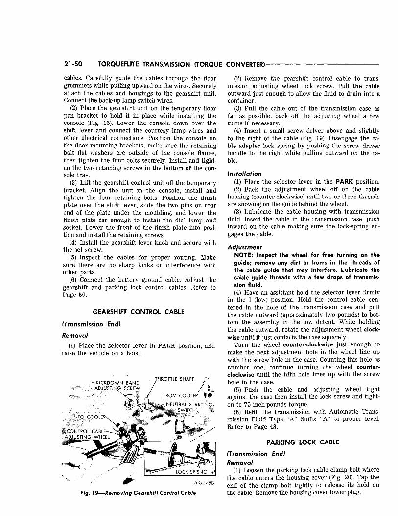
21-50 TORQUEFLITE TRANSMISSION (TORQUE CONVERTER)
cables. Carefully guide the cables through the floor grommets while pulling upward on the wires. Securely attach the cables and housings to the gearshift unit. Connect the back-up lamp switch wires.
(2) Place the gearshift unit on the temporary floor pan bracket to hold it in place while installing the console (Fig. 16). Lower the console down over the shift lever and connect the courtesy lamp wires and other electrical connections. Position the console on the floor mounting brackets, make sure the retaining bolt flat washers are outside of the console flange, then tighten the four bolts securely. Install and tighten the two retaining screws in the bottom of the console tray.
(3) Lift the gearshift control unit off the temporary bracket. Align the unit in the console, install and tighten the four retaining bolts. Position the finish plate over the shift lever, slide the two pins on rear end of the plate under the moulding, and lower the finish plate far enough to install the dial lamp and socket. Lower the front of the finish plate into position and install the retaining screws.
(4) Install the gearshift lever knob and secure with the set screw.
(5) Inspect the cables for proper routing. Make sure there are no sharp kinks or interference with other parts.
(6) Connect the battery ground cable. Adjust the gearshift and parking lock control cables. Refer to Page 50.
GEARSHIFT CONTROL CABLE
(Transmission End)
Removal
(1) Place the selector lever in PARK position, and raise the vehicle on a hoist.
K I C K D O W N B A N D A D J U S T I N G S C R E W
X
T O C O O L E R N
C O N T R O L C A B L E S -A D J U S T I N G W H E E L
:»3S
T H R O T T L E S H A F T
F R O M C O O L E R ? &
N E U T R A L S T A R T I N G S W I T C H
L O C K S P R I N G
6 3 x 5 7 8 B
Fig. 79—Remov ing Gearshift Control Cable
(2) Remove the gearshift control cable to transmission adjusting wheel lock screw. Pull the cable outward just enough to allow the fluid to drain into a container.
(3) Pull the cable out of the transmission case as far as possible, back off the adjusting wheel a few turns if necessary.
(4) Insert a small screw driver above and slightly to the right of the cable (Fig. 19). Disengage the cable adapter lock spring by pushing the screw driver handle to the right while pulling outward on the cable.
Installation (1) Place the selector lever in the PARK position. (2) Back the adjustment wheel off on the cable
housing (counter-clockwise) until two or three threads are showing on the guide behind the wheel.
(3) Lubricate the cable housing with transmission fluid, insert the cable in the transmission case, push inward on the cable making sure the lock-spring engages the cable.
Adjustment NOTE: Inspect the wheel for free turning on the guide; remove any dirt or burrs in the threads of the cable guide that may interfere. Lubricate the cable guide threads with a few drops of transmission fluid. (4) Have an assistant hold the selector lever firmly
in the 1 (low) position. Hold the control cable centered in the hole of the transmission case and pull the cable outward (approximately two pounds) to bottom the assembly in the low detent. While holding the cable outward, rotate the adjustment wheel clockwise until it just contacts the case squarely.
Turn the wheel counter-clockwise just enough to make the next adjustment hole in the wheel line up with the screw hole in the case. Counting this hole as number one, continue turning the wheel counterclockwise until the fifth hole lines up with the screw hole in the case.
(5) Push the cable and adjusting wheel tight against the case then install the lock screw and tighten to 75 inch-pounds torque.
(6) Refill the transmission with Automatic Transmission Fluid Type "A" Suffix "A" to proper level. Refer to Page 43.
PARKING LOCK CABLE
(Transmission End) Removal
(1) Loosen the parking lock cable clamp bolt where the cable enters the housing cover (Fig. 20). Tap the end of the clamp bolt tightly to release its hold on the cable. Remove the housing cover lower plug.
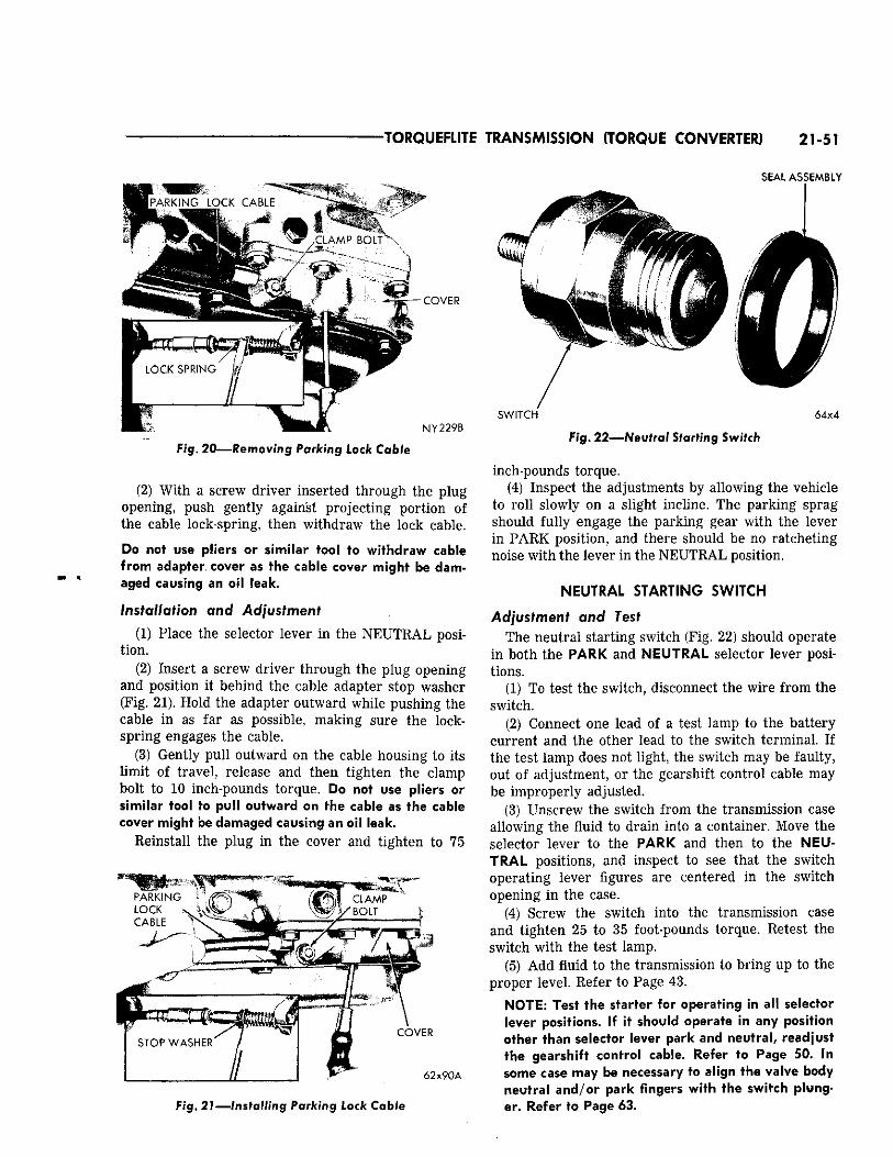
TORQUEFLITE TRANSMISSION (TORQUE CONVERTER) 21-51
S E A L A S S E M B L Y
S P A R K I N G L O C K C A B L E
, C L A M P B O L T
- C O V E R
N Y 2 2 9 B
Fig. 2 0 — R e m o v i n g Parking Lock Cable
(2) With a screw driver inserted through the plug opening, push gently against projecting portion of the cable lock-spring, then withdraw the lock cable.
Do not use pliers or similar tool to withdraw cable from adapter cover as the cable cover might be damaged causing an oil leak.
Installation and Adjustment
(1) Place the selector lever in the NEUTRAL position.
(2) Insert a screw driver through the plug opening and position it behind the cable adapter stop washer (Fig. 21). Hold the adapter outward while pushing the cable in as far as possible, making sure the lock-spring engages the cable.
(3) Gently pull outward on the cable housing to its limit of travel, release and then tighten the clamp bolt to 10 inch-pounds torque. Do not use pliers or similar tool to pull outward on the cable as the cable cover might be damaged causing an oil leak.
Reinstall the plug in the cover and tighten to 75
^ C L A M P
C O V E R
6 2 x 9 0 A
S W I T C H 6 4 x 4
Fig. 22—Neutral Starting Switch
Fig. 21—Installing Parking Lock Cable
inch-pounds torque. (4) Inspect the adjustments by allowing the vehicle
to roll slowly on a slight incline. The parking sprag should fully engage the parking gear with the lever in PARK position, and there should be no ratcheting noise with the lever in the NEUTRAL position.
NEUTRAL STARTING SWITCH
Adjustment and Test The neutral starting switch (Fig. 22) should operate
in both the PARK and NEUTRAL selector lever positions.
(1) To test the switch, disconnect the wire from the switch.
(2) Connect one lead of a test lamp to the battery current and the other lead to the switch terminal. If the test lamp does not light, the switch may be faulty, out of adjustment, or the gearshift control cable may be improperly adjusted.
(3) Unscrew the switch from the transmission case allowing the fluid to drain into a container. Move the selector lever to the PARK and then to the NEUTRAL positions, and inspect to see that the switch operating lever figures are centered in the switch opening in the case.
(4) Screw the switch into the transmission case and tighten 25 to 35 foot-pounds torque. Retest the switch with the test lamp.
(5) Add fluid to the transmission to bring up to the proper level. Refer to Page 43.
NOTE: Test the starter for operating in all selector lever positions. If it should operate in any position other than selector lever park and neutral, readjust the gearshift control cable. Refer to Page 50. In some case may be necessary to align the valve body neutral and/or park fingers with the switch plunger. Refer to Page 63.
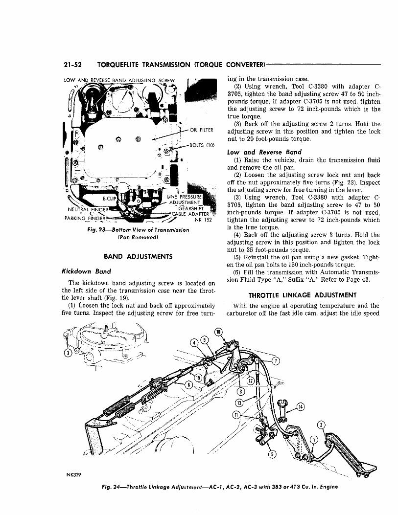
21-52 TORQUEFLITE TRANSMISSION (TORQUE CONVERTER)
L O W A N D R E V E R S E B A N D A D J U S T I N G S C R E W
O I L F I L T E R
B O L T S (10)
N E U T R A L F I N G E R
P A R K I N G F I N G E R
A D J U S T M E N T ^
' G E A R S H I F T
T C A B L E A D A P T E R
N K 152
Fig. 23—-Bottom View of Transmission (Pan Removed)
BAND ADJUSTMENTS
Kickdown Band
The kickdown band adjusting screw is located on the left side of the transmission case near the throttle lever shaft (Fig. 19).
(1) Loosen the lock nut and back off approximately five turns. Inspect the adjusting screw for free turn
ing in the transmission case. (2) Using wrench, Tool C-3380 with adapter C-
3705, tighten the band adjusting screw 47 to 50 inch-pounds torque. If adapter C-3705 is not used, tighten the adjusting screw to 72 inch-pounds which is the true torque.
(3) Back off the adjusting screw 2 turns. Hold the adjusting screw in this position and tighten the lock nut to 29 foot-pounds torque.
Low and Reverse Band (1) Raise the vehicle, drain the transmission fluid
and remove the oil pan. (2) Loosen the adjusting screw lock nut and back
off the nut approximately five turns (Fig. 23). Inspect the adjusting screw for free turning in the lever.
(3) Using wrench, Tool C-3380 with adapter C-3705, tighten the band adjusting screw to 47 to 50 inch-pounds torque. If adapter C-3705 is not used, tighten the adjusting screw to 72 inch-pounds which is the true torque.
(4) Back off the adjusting screw 3 turns. Hold the adjusting screw in this position and tighten the lock nut to 35 foot-pounds torque.
(5) Reinstall the oil pan using a new gasket. Tighten the oil pan bolts to 150 inch-pounds torque.
(6) Fill the transmission with Automatic Transmission Fluid Type "A," Suffix "A." Refer to Page 43.
THROTTLE LINKAGE ADJUSTMENT
With the engine at operating temperature and the carburetor off the fast idle cam, adjust the idle speed
NK329
Fig. 24—Throttle Linkage Adjustment—AC-1, A C - 2 , AC-3 with 383 or 413 Cu. In. Engine
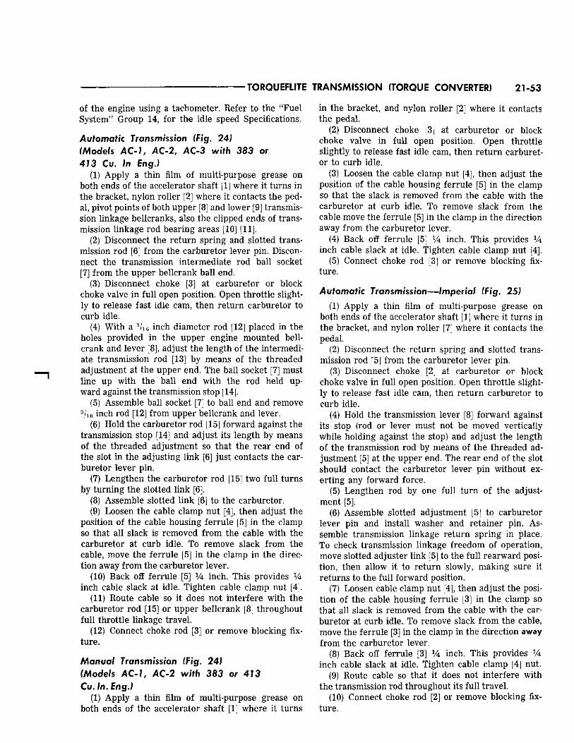
TORQUEFLITE TRANSMISSION (TORQUE CONVERTER) 21-53
of the engine using a tachometer. Refer to the "Fuel System" Group 14, for the idle speed Specifications.
Automatic Transmission (Fig. 24) (Models A C - 1 , AC-2 , AC-3 wi'fh 383 or 413 Cu. In Eng.)
(1) Apply a thin film of multi-purpose grease on both ends of the accelerator shaft [1] where it turns in the bracket, nylon roller [2] where it contacts the pedal, pivot points of both upper [8] and lower [9] transmission linkage bellcranks, also the clipped ends of transmission linkage rod bearing areas [10] [11].
(2) Disconnect the return spring and slotted transmission rod [6] from the carburetor lever pin. Disconnect the transmission intermediate rod ball socket [7] from the upper bellcrank ball end.
(3) Disconnect choke [3] at carburetor or block choke valve in full open position. Open throttle slightly to release fast idle cam, then return carburetor to curb idle.
(4) With a 3 / ie inch diameter rod [12] placed in the holes provided in the upper engine mounted bell-crank and lever [8], adjust the length of the intermediate transmission rod [13] by means of the threaded adjustment at the upper end. The ball socket [7] must line up with the ball end with the rod held upward against the transmission stop [14].
(5) Assemble ball socket [7] to ball end and remove 3 / 1 6 inch rod [12] from upper bellcrank and lever.
(6) Hold the carburetor rod [15] forward against the transmission stop [14] and adjust its length by means of the threaded adjustment so that the rear end of the slot in the adjusting link [6] just contacts the carburetor lever pin.
(7) Lengthen the carburetor rod [15] two full turns by turning the slotted link [6].
(8) Assemble slotted link [6] to the carburetor. (9) Loosen the cable clamp nut [4], then adjust the
position of the cable housing ferrule [5] in the clamp so that all slack is removed from the cable with the carburetor at curb idle. To remove slack from the cable, move the ferrule [5] in the clamp in the direction away from the carburetor lever.
(10) Back off ferrule [5] xk inch. This provides inch cable slack at idle. Tighten cable clamp nut [4].
(11) Route cable so it does not interfere with the carburetor rod [15] or upper bellcrank [8] throughout full throttle linkage travel.
(12) Connect choke rod [3] or remove blocking fixture.
Manual Transmission (Fig. 24) (Models AC-1 , AC-2 with 383 or 413 Cu. In. Eng.)
(1) Apply a thin film of multi-purpose grease on both ends of the accelerator shaft [1] where it turns
in the bracket, and nylon roller [2] where it contacts the pedal.
(2) Disconnect choke [3] at carburetor or block choke valve in full open position. Open throttle slightly to release fast idle cam, then return carburetor to curb idle.
(3) Loosen the cable clamp nut [4], then adjust the position of the cable housing ferrule [51 in the clamp so that the slack is removed from the cable with the carburetor at curb idle. To remove slack from the cable move the ferrule [5] in the clamp in the direction away from the carburetor lever.
(4) Back off ferrule [5] Vk inch. This provides xk inch cable slack at idle. Tighten cable clamp nut [4].
(5) Connect choke rod [3] or remove blocking fixture.
Automatic Transmission—Imperial (Fig. 25) (1) Apply a thin film of multi-purpose grease on
both ends of the accelerator shaft [1] where it turns in the bracket, and nylon roller [7] where it contacts the pedal.
(2) Disconnect the return spring and slotted transmission rod [5] from the carburetor lever pin.
(3) Disconnect choke [2] at carburetor or block choke valve in full open position. Open throttle slightly to release fast idle cam, then return carburetor to curb idle.
(4) Hold the transmission lever [8] forward against its stop (rod or lever must not be moved vertically while holding against the stop) and adjust the length of the transmission rod by means of the threaded adjustment [5] at the upper end. The rear end of the slot should contact the carburetor lever pin without exerting any forward force.
(5) Lengthen rod by one full turn of the adjustment [5].
(6) Assemble slotted adjustment [5] to carburetor lever pin and install washer and retainer pin. Assemble transmission linkage return spring in place. To check transmission linkage freedom of operation, move slotted adjuster link [5] to the full rearward position, then allow it to return slowly, making sure it returns to the full forward position.
(7) Loosen cable clamp nut [4], then adjust the position of the cable housing ferrule [3] in the clamp so that all slack is removed from the cable with the carburetor at curb idle. To remove slack from the cable, move the ferrule [3] in the clamp in the direction away from the carburetor lever.
(8) Back off ferrule [3] V* inch. This provides V* inch cable slack at idle. Tighten cable clamp [4] nut.
(9) Route cable so that it does not interfere with the transmission rod throughout its full travel.
(10) Connect choke rod [2] or remove blocking fixture.
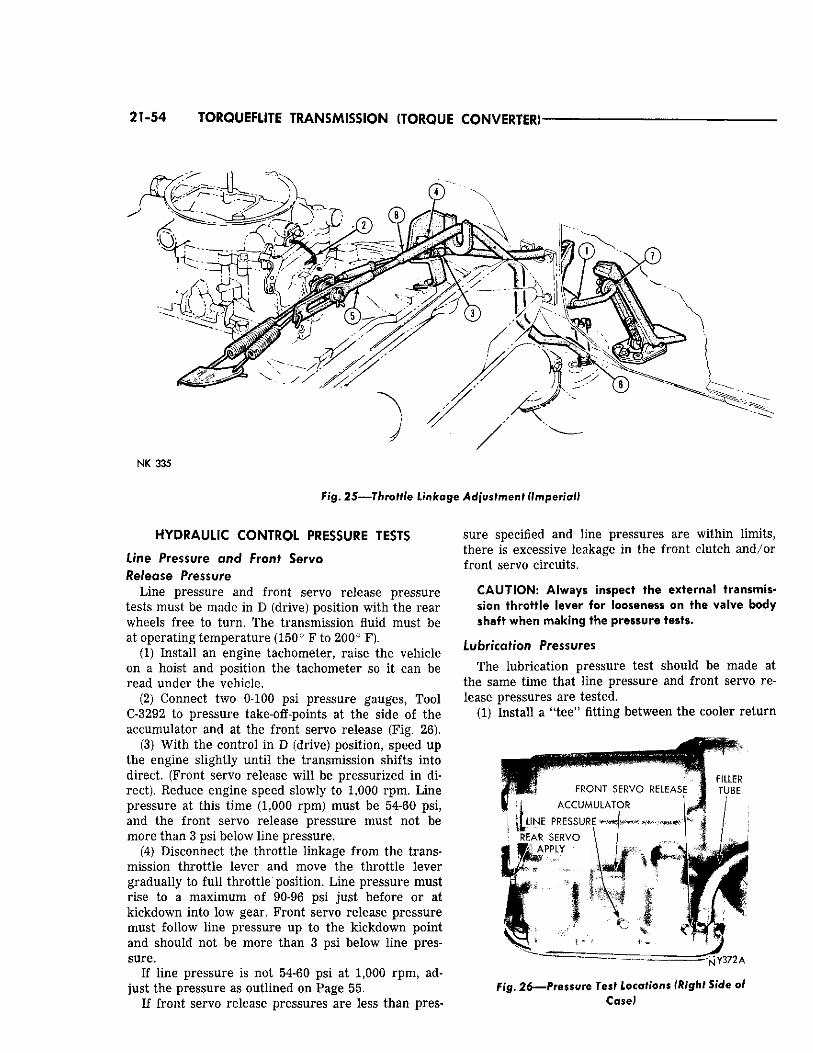
21-54 TORQUEFLITE TRANSMISSION (TORQUE CONVERTER)
NK 335
F i g . 25—Throt t le Linkage Adjustment (Imperial)
HYDRAULIC CONTROL PRESSURE TESTS
Line Pressure and Front Servo Release Pressure
Line pressure and front servo release pressure tests must be made in D (drive) position with the rear wheels free to turn. The transmission fluid must be at operating temperature (150° F to 200° F).
(1) Install an engine tachometer, raise the vehicle on a hoist and position the tachometer so it can be read under the vehicle.
(2) Connect two 0-100 psi pressure gauges, Tool C-3292 to pressure take-off-points at the side of the accumulator and at the front servo release (Fig. 26).
(3) With the control in D (drive) position, speed up the engine slightly until the transmission shifts into direct. (Front servo release will be pressurized in direct). Reduce engine speed slowly to 1,000 rpm. Line pressure at this time (1,000 rpm) must be 54-60 psi, and the front servo release pressure must not be more than 3 psi below line pressure.
(4) Disconnect the throttle linkage from the transmission throttle lever and move the throttle lever gradually to full throttle position. Line pressure must rise to a maximum of 90-96 psi just before or at kickdown into low gear. Front servo release pressure must follow line pressure up to the kickdown point and should not be more than 3 psi below line pressure.
If line pressure is not 54-60 psi at 1,000 rpm, adjust the pressure as outlined on Page 55.
If front servo release pressures are less than pres
sure specified and line pressures are within limits, there is excessive leakage in the front clutch and/or front servo circuits.
CAUTION: Always inspect the external transmission throttle lever for looseness on the valve body shaft when making the pressure tests.
Lubrication Pressures The lubrication pressure test should be made at
the same time that line pressure and front servo release pressures are tested.
(1) Install a "tee" fitting between the cooler return
Fig. 2 6 — P r e s s u r e Test Locations (Right Side of Case)
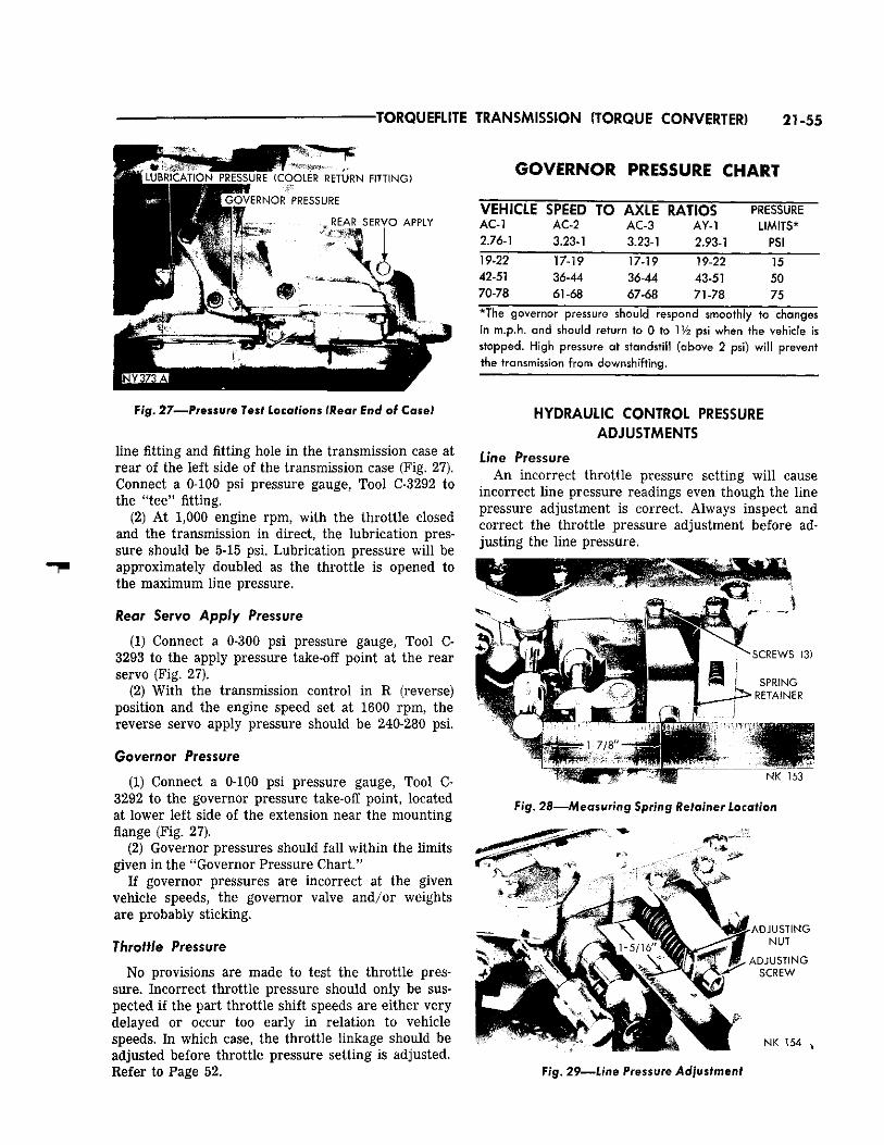
TORQUEFLITE TRANSMISSION (TORQUE CONVERTER) 21-55
L U B R I C A T I O N P R E S S U R E ( C O O L E R R E T U R N F I T T I N G )
.. G O V E R N O R P R E S S U R E
I . . R E A R S E R V O A P P L Y
Fig. 27—Pressure Tesi Locations {Wear End of Case!
line fitting and fitting hole in the transmission case at rear of the left side of the transmission case (Fig, 27). Connect a 0-100 psi pressure gauge, Tool C-3292 to the "tee" fitting.
(2) At 1,000 engine rpm, with the throttle closed and the transmission in direct, the lubrication pressure should be 5-15 psi. Lubrication pressure will be approximately doubled as the throttle is opened to the maximum line pressure.
Rear Servo Apply Pressure
(1) Connect a 0-300 psi pressure gauge, Tool C-3293 to the apply pressure take-off point at the rear servo (Fig. 27).
(2) With the transmission control in R (reverse) position and the engine speed set at 1600 rpm, the reverse servo apply pressure should be 240-280 psi.
Governor Pressure
(1) Connect a 0-100 psi pressure gauge, Tool C-3292 to the governor pressure take-off point, located at lower left side of the extension near the mounting flange (Fig. 27).
(2) Governor pressures should fall within the limits given in the "Governor Pressure Chart."
If governor pressures are incorrect at the given vehicle speeds, the governor valve and/or weights are probably sticking.
Throttle Pressure
No provisions are made to test the throttle pressure. Incorrect throttle pressure should only be suspected if the part throttle shift speeds are either very delayed or occur too early in relation to vehicle speeds. In which case, the throttle linkage should be adjusted before throttle pressure setting is adjusted. Refer to Page 52.
GOVERNOR PRESSURE CHART
VEHICLE SPEED TO AXLE RATIOS PRESSURE A C - l A C 2 AC-3 AY-1 LIMITS* 2.76-1 3.23-1 3.23-1 2.93-1 PSI 19-22 17-19 17-19 19-22 15 42-51 36-44 36-44 43-51 50 70-78 61-68 67-68 71-78 75
in m.p.h. and should return to 0 to IV2 psi when the vehicle is stopped. High pressure at standstill (above 2 psi) will prevent the transmission from downshifting.
HYDRAULIC CONTROL PRESSURE ADJUSTMENTS
Line Pressure An incorrect throttle pressure setting will cause
incorrect line pressure readings even though the line pressure adjustment is correct. Always inspect and correct the throttle pressure adjustment before adjusting the line pressure.
• 1 - 7 / 8 "
^ S C R E W S (3)
S P R I N G
. 3 * R E T A I N E R
N K 153
Fig. 28—Measuring Spring Retainer Location
P I
IP if i; . . - A D J U S T I N G
N U T
A D J U S T I N G S C R E W
•
S • f " 'MA N K 1 5 4
Fig. 29—Line Pressure Adjustment
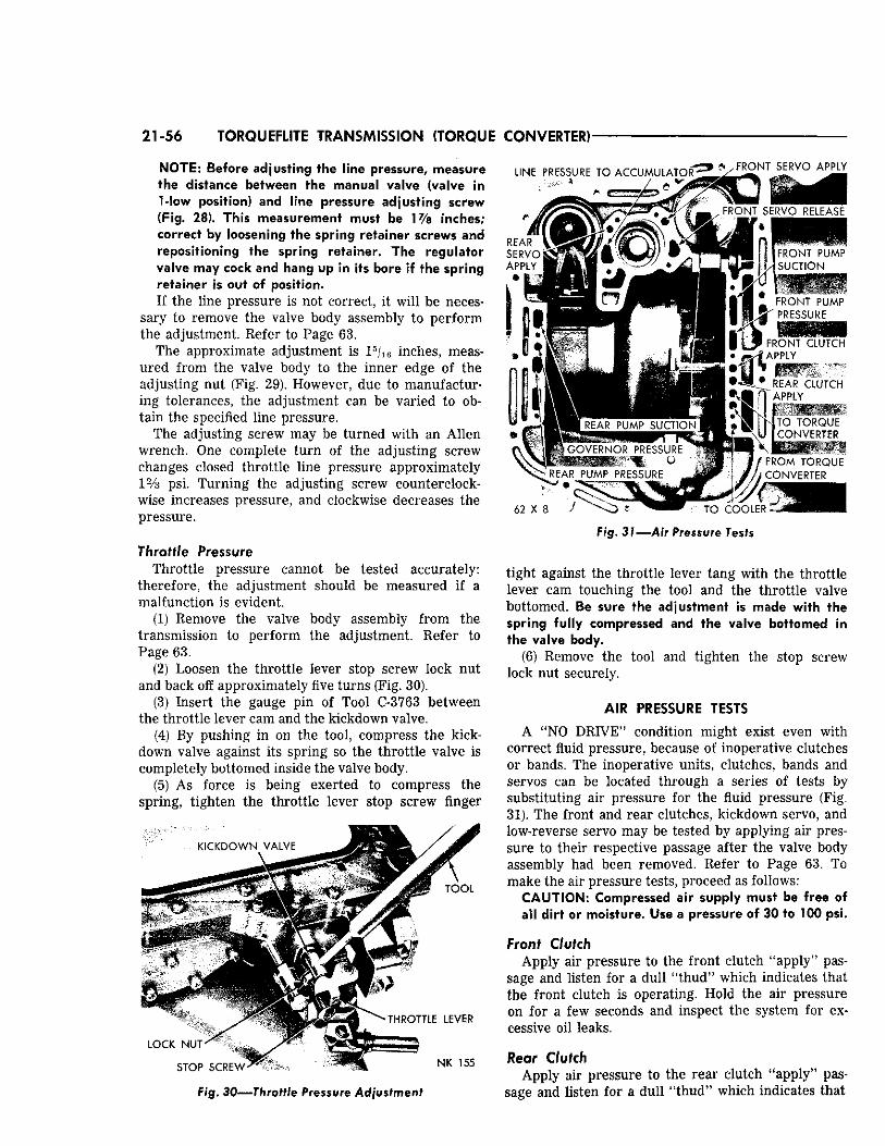
21-56 TORQUEFLITE TRANSMISSION (TORQUE CONVERTER)
NOTE: Before adjust ing the l ine pressure, measure the distance between the manual valve (valve in 1-low position) and l ine pressure adjust ing screw (Fig. 28). This measurement must be 1 % inches; correct by loosening the spr ing retainer screws and reposi t ioning the spr ing retainer. The regula tor valve may cock and hang up in its bore i f the spr ing retainer is out of posi t ion. If the line pressure is not correct, it will be neces
sary to remove the valve body assembly to perform the adjustment. Refer to Page 63.
The approximate adjustment is 1 5 / 1 6 inches, measured from the valve body to the inner edge of the adjusting nut (Fig. 29). However, due to manufacturing tolerances, the adjustment can be varied to obtain the specified line pressure.
The adjusting screw may be turned with an Allen wrench. One complete turn of the adjusting screw changes closed throttle line pressure approximately 1% psi. Turning the adjusting screw counterclockwise increases pressure, and clockwise decreases the pressure.
Throttle Pressure Throttle pressure cannot be tested accurately:
therefore, the adjustment should be measured if a malfunction is evident.
(1) Remove the valve body assembly from the transmission to perform the adjustment. Refer to Page 63.
(2) Loosen the throttle lever stop screw lock nut and back off approximately five turns (Fig. 30).
(3) Insert the gauge pin of Tool C-3763 between the throttle lever cam and the kickdown valve.
(4) By pushing in on the tool, compress the kick-down valve against its spring so the throttle valve is completely bottomed inside the valve body.
(5) As force is being exerted to compress the spring, tighten the throttle lever stop screw finger
KICKDOWN VALVE
LINE PRESSURE TO ACCUMULATOR
THROTTLE LEVER
LOCK NUT ' " • }P-> rrz
STOP S C R E W -> N K 155
F/g. 30—Throttle Pressure Adjustment
6 2 X 8
FRONT SERVO APPLY
~ . FRONT SERVO RELEASE
i f w. i. FRONT PUMP
/< SUCTION
FRONT PUMP PRESSURE
I I ' ^ FRONT CLUTCH I - JP • <~v* APPLY
i REAR CLUTCH ~ APPLY
N T O TORQUE CONVERTER
FROM TORQUE CONVERTER
TO COOLER
F/g. 37—Air Pressure Tests
tight against the throttle lever tang with the throttle lever cam touching the tool and the throttle valve bottomed. Be sure the adjustment is made w i t h the spr ing fu l ly compressed and the valve bot tomed in the valve body.
(6) Remove the tool and tighten the stop screw lock nut securely.
AIR PRESSURE TESTS
A "NO DRIVE" condition might exist even with correct fluid pressure, because of inoperative clutches or bands. The inoperative units, clutches, bands and servos can be located through a series of tests by substituting air pressure for the fluid pressure (Fig. 31). The front and rear clutches, kickdown servo, and low-reverse servo may be tested by applying air pressure to their respective passage after the valve body assembly had been removed. Refer to Page 63. To make the air pressure tests, proceed as follows:
C A U T I O N : Compressed air supply must be free of a l l d i r t or moisture. Use a pressure of 30 to 100 psi.
Front Clutch Apply air pressure to the front clutch "apply" pas
sage and listen for a dull "thud" which indicates that the front clutch is operating. Hold the air pressure on for a few seconds and inspect the system for excessive oil leaks.
Rear Clutch Apply air pressure to the rear clutch "apply" pas
sage and listen for a dull "thud" which indicates that
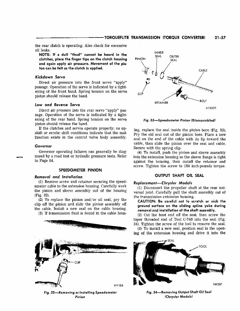
TORQUEFLITE TRANSMISSION (TORQUE CONVERTER) 21-57
the rear clutch is operating. Also check for excessive oil leaks.
NOTE: If a dull "thud" cannot be heard In the clutches, place the finger tips on the clutch housing and again apply air pressure. Movement of the piston can be felt as the clutch is applied.
Kickdown Servo Direct air pressure into the front servo "apply"
passage. Operation of the servo is indicated by a tightening of the front band. Spring tension on the servo piston should release the band.
Low and Reverse Servo Direct air pressure into the rear servo "apply" pas
sage. Operation of the servo is indicated by a tightening of the rear band. Spring tension on the servo piston should release the band.
If the clutches and servos operate properly; no upshift or erratic shift conditions indicate that the malfunction exists in the control valve body assembly.
Governor Governor operating failures can generally be diag
nosed by a road test or hydaulic pressure tests. Refer to Page 54.
SPEEDOMETER PINION
Removal and installation (1) Remove screw and retainer securing the speed
ometer cable to the extension housing. Carefully work the pinion and sleeve assembly out of the housing (Fig. 32).
(2) To replace the pinion and/or oil seal, pry the clip off the pinion and slide the pinion assembly off the cable. Install a new seal on the cable housing.
(3) If transmission fluid is found in the cable hous-
J ^ V — C L I P v N Y 1 8 6
Fig. 32—Removing or Installing Speedometer Pinion
P I N I O N
I N N E R
S E A L O U T E R
C A B L E
C L I P
R E T A I N E R B O L T
6 1 X 3 5 9
Fig. 33—Speedometer Pinion (Disassembled)
ing, replace the seal inside the pinion bore (Fig. 33). Pry the old seal out of the pinion bore. Place a new seal on the end of the cable with its lip toward the cable, then slide the pinion over the seal and cable. Secure with the spring clip.
(4) To install, push the pinion and sleeve assembly into the extension housing so the sleeve flange is tight against the housing, then install the retainer and screw. Tighten the screw to 150 inch-pounds torque.
OUTPUT SHAFT OIL SEAL
Replacement—Chrysler Models (1) Disconnect the propeller shaft at the rear uni
versal joint. Carefully pull the shaft assembly out of the transmission extension housing.
CAUTION: Be careful not to scratch or nick the ground surface on the sliding spline yoke during removal and installation of the shaft assembly. (2) Cut the boot end off the seal, then screw the
taper threaded end of Tool C-748 into the seal (Fig. 34). Tighten the screw of the tool to remove the seal.
(3) To install a new seal, position seal in the opening of the extension housing and drive it into the
S E A L
- T O O L
N K 2 8 7
Fig. 34—Removing Output Shaft Oil Seal (Chrysler Models)
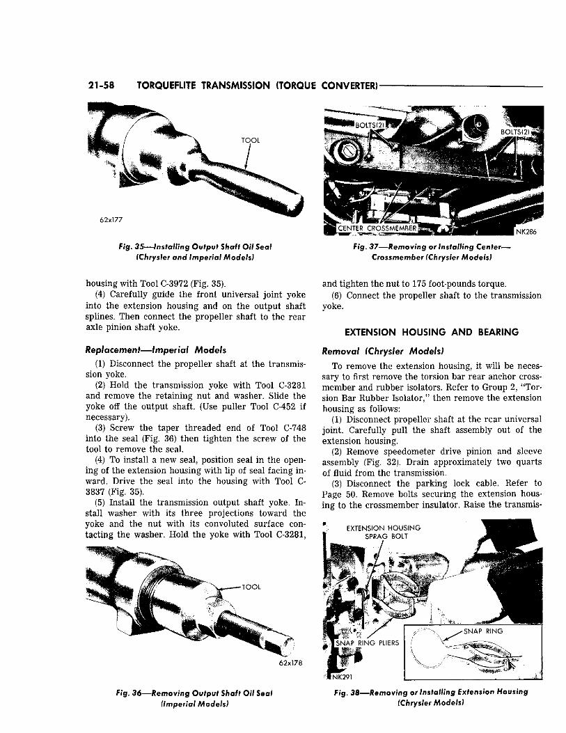
21-58 TORQUEFLITE TRANSMISSION (TORQUE CONVERTER)
Fig. 35—installing Output Shaft Oil Seal Fig. 37—Removing or Installing Center— (Chrysler and Imperial Models) Crossmember (Chrysler Models)
housing with Tool C-3972 (Fig. 35). (4) Carefully guide the front universal joint yoke
into the extension housing and on the output shaft splines. Then connect the propeller shaft to the rear axle pinion shaft yoke.
Replacement—Imperial Models (1) Disconnect the propeller shaft at the transmis
sion yoke. (2) Hold the transmission yoke with Tool C-3281
and remove the retaining nut and washer. Slide the yoke off the output shaft. (Use puller Tool C-452 if necessary).
(3) Screw the taper threaded end of Tool C-748 into the seal (Fig. 36) then tighten the screw of the tool to remove the seal.
(4) To install a new seal, position seal in the opening of the extension housing with lip of seal facing inward. Drive the seal into the housing with Tool C-3837 (Fig. 35).
(5) Install the transmission output shaft yoke. Install washer with its three projections toward the yoke and the nut with its convoluted surface contacting the washer. Hold the yoke with Tool C-3281,
' ****** " "V* \
T O O L
62x178
and tighten the nut to 175 foot-pounds torque. (6) Connect the propeller shaft to the transmission
yoke.
EXTENSION HOUSING AND BEARING
Removal (Chrysler Models)
To remove the extension housing, it will be necessary to first remove the torsion bar rear anchor cross-member and rubber isolators. Refer to Group 2, 'Torsion Bar Rubber Isolator," then remove the extension housing as follows:
(1) Disconnect propeller shaft at the rear universal joint. Carefully pull the shaft assembly out of the extension housing.
(2) Remove speedometer drive pinion and sleeve assembly (Fig. 32). Drain approximately two quarts of fluid from the transmission.
(3) Disconnect the parking lock cable. Refer to Page 50. Remove bolts securing the extension housing to the crossmember insulator. Raise the transmis-
E X T E N S I O N H O U S I N G
S P R A G B O L T
F ig . 36—Removing Output Shaft Oil Seal (Imperial Models)
Fig. 38—Removing or Installing Extension Housing (Chrysler Models)
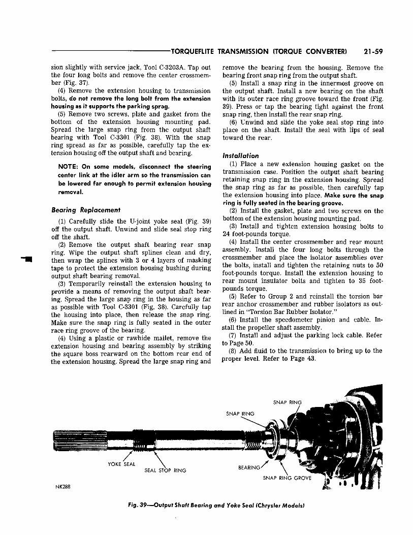
TORQUEFLITE TRANSMISSION (TORQUE CONVERTER) 21-59
sion slightly with service jack, Tool C-3203A. Tap out the four long bolts and remove the center crossmember (Fig. 37).
(4) Remove the extension housing to transmission bolts, do not remove the long bolt from the extension housing as it supports the parking sprag.
(5) Remove two screws, plate and gasket from the bottom of the extension housing mounting pad. Spread the large snap ring from the output shaft bearing with Tool C-3301 (Fig. 38). With the snap ring spread as far as possible, carefully tap the extension housing off the output shaft and bearing.
NOTE: On some models, disconnect the steering center link at the idler arm so the transmission can be lowered far enough to permit extension housing removal.
Bearing Replacement
(1) Carefully slide the U-joint yoke seal (Fig. 39) off the output shaft. Unwind and slide seal stop ring off the shaft.
(2) Remove the output shaft bearing rear snap ring. Wipe the output shaft splines clean and dry, then wrap the splines with 3 or 4 layers of masking tape to protect the extension housing bushing during output shaft bearing removal.
(3) Temporarily reinstall the extension housing to provide a means of removing the output shaft bearing. Spread the large snap ring in the housing as far as possible with Tool C-3301 (Fig. 38). Carefully tap the housing into place, then release the snap ring. Make sure the snap ring is fully seated in the outer race ring groove of the bearing.
(4) Using a plastic or rawhide mallet, remove the extension housing and bearing assembly by striking the square boss rearward on the bottom rear end of the extension housing. Spread the large snap ring and
remove the bearing from the housing. Remove the bearing front snap ring from the output shaft.
(5) Install a snap ring in the innermost groove on the output shaft. Install a new bearing on the shaft with its outer race ring groove toward the front (Fig. 39). Press or tap the bearing tight against the front snap ring, then install the rear snap ring.
(6) Unwind and slide the yoke seal stop ring into place on the shaft. Install the seal with lips of seal toward the rear.
Installation (1) Place a new extension housing gasket on the
transmission case. Position the output shaft bearing retaining snap ring in the extension housing. Spread the snap ring as far as possible, then carefully tap the extension housing into place. Make sure the snap ring is fully seated in the bearing groove.
(2) Install the gasket, plate and two screws on the bottom of the extension housing mounting pad.
(3) Install and tighten extension housing bolts to 24 foot-pounds torque.
(4) Install the center crossmember and rear mount assembly. Install the four long bolts through the crossmember and place the isolator assemblies over the bolts, install and tighten the retaining nuts to 50 foot-pounds torque. Install the extension housing to rear mount insulator bolts and tighten to 35 footpounds torque.
(5) Refer to Group 2 and reinstall the torsion bar rear anchor crossmember and rubber isolators as outlined in "Torsion Bar Rubber Isolator."
(6) Install the speedometer pinion and cable. Install the propeller shaft assembly.
(7) Install and adjust the parking lock cable. Refer to Page 50.
(8) Add fluid to the transmission to bring up to the proper level. Refer to Page 43.
Fig. 3 9 — O u f p u f Shaff Bearing and Yoke S e a l (Chrysler Models)
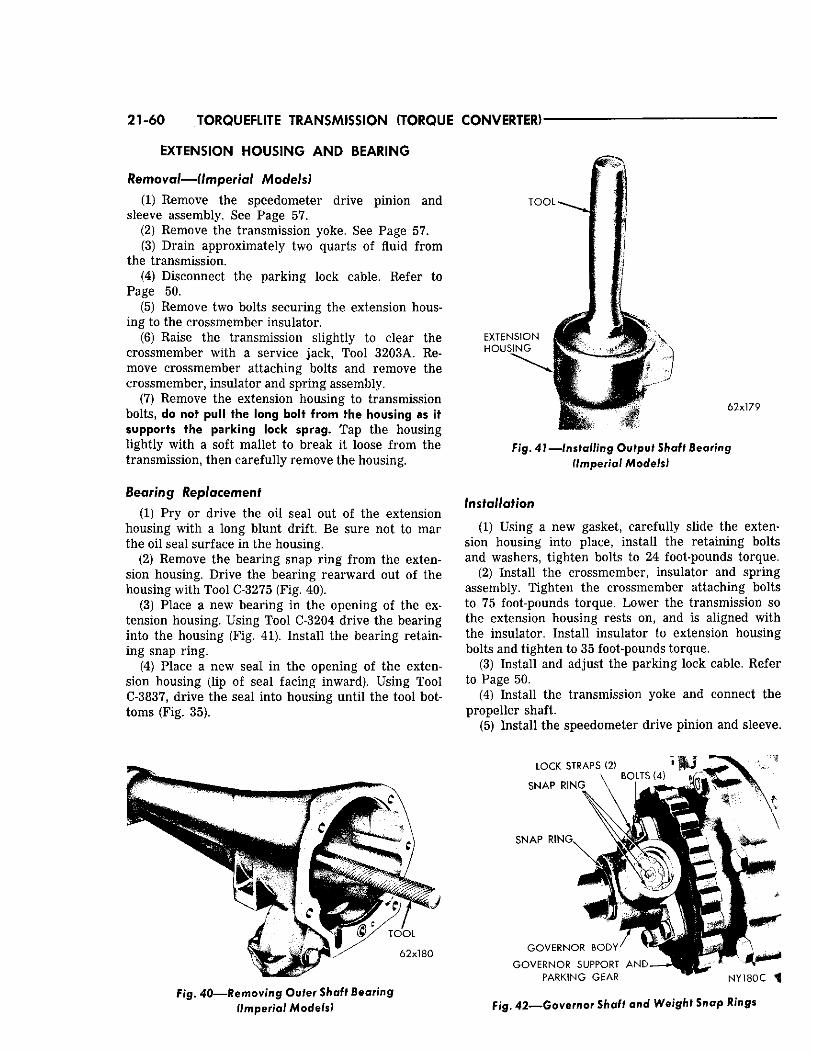
21-60 TORQUEFLITE TRANSMISSION (TORQUE CONVERTER)
EXTENSION HOUSING AND BEARING
Removal—(Imperial Models)
(1) Remove the speedometer drive pinion and sleeve assembly. See Page 57.
(2) Remove the transmission yoke. See Page 57. (3) Drain approximately two quarts of fluid from
the transmission. (4) Disconnect the parking lock cable. Refer to
Page 50. (5) Remove two bolts securing the extension hous
ing to the crossmember insulator. (6) Raise the transmission slightly to clear the
crossmember with a service jack, Tool 3203A. Remove crossmember attaching bolts and remove the crossmember, insulator and spring assembly.
(7) Remove the extension housing to transmission bolts, do not pull the long bolt from the housing as it supports the parking lock sprag. Tap the housing lightly with a soft mallet to break it loose from the transmission, then carefully remove the housing.
Bearing Replacement
(1) Pry or drive the oil seal out of the extension housing with a long blunt drift. Be sure not to mar the oil seal surface in the housing.
(2) Remove the bearing snap ring from the extension housing. Drive the bearing rearward out of the housing with Tool C-3275 (Fig. 40).
(3) Place a new bearing in the opening of the extension housing. Using Tool C-3204 drive the bearing into the housing (Fig. 41). Install the bearing retaining snap ring.
(4) Place a new seal in the opening of the extension housing (lip of seal facing inward). Using Tool C-3837, drive the seal into housing until the tool bottoms (Fig. 35).
F i g . 4 0 — R e m o v i n g Oufer Shaft Bearing (Imperial Models)
6 2 x 1 7 9
F i g . 41—Installing Output Shaft Bearing (Imperial Models)
Installation
(1) Using a new gasket, carefully slide the extension housing into place, install the retaining bolts and washers, tighten bolts to 24 foot-pounds torque.
(2) Install the crossmember, insulator and spring assembly. Tighten the crossmember attaching bolts to 75 foot-pounds torque. Lower the transmission so the extension housing rests on, and is aligned with the insulator. Install insulator to extension housing bolts and tighten to 35 foot-pounds torque.
(3) Install and adjust the parking lock cable. Refer to Page 50.
(4) Install the transmission yoke and connect the propeller shaft.
(5) Install the speedometer drive pinion and sleeve.
F ig . 42—Governor Shaft and Weight Snap Rings
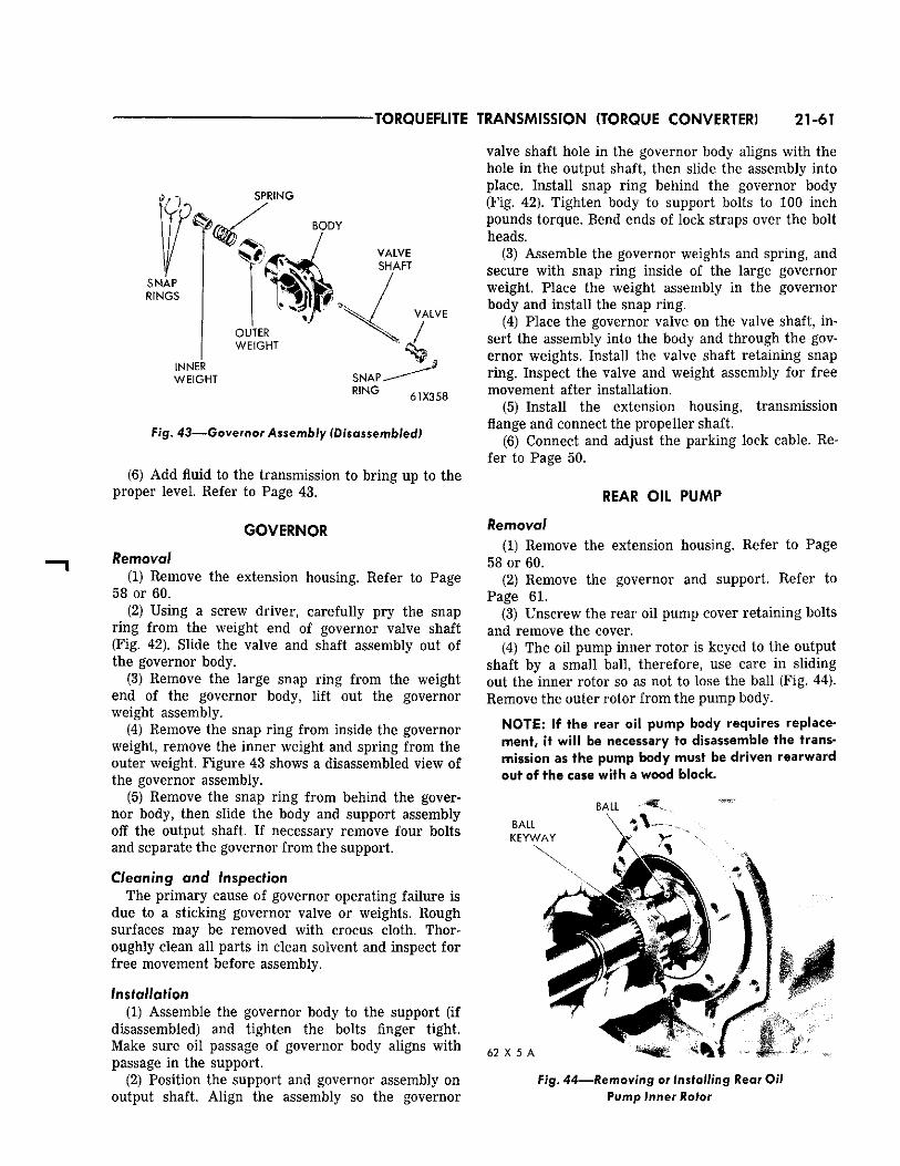
TORQUEFLITE TRANSMISSION (TORQUE CONVERTER) 21-61
R I N G 61X358
Fig. 43—Governor Assembly (Disassembled)
(6) Add fluid to the transmission to bring up to the proper level. Refer to Page 43.
GOVERNOR
Removal (1) Remove the extension housing. Refer to Page
58 or 60. (2) Using a screw driver, carefully pry the snap
ring from the weight end of governor valve shaft (Fig. 42). Slide the valve and shaft assembly out of the governor body.
(3) Remove the large snap ring from the weight end of the governor body, lift out the governor weight assembly.
(4) Remove the snap ring from inside the governor weight, remove the inner weight and spring from the outer weight. Figure 43 shows a disassembled view of the governor assembly.
(5) Remove the snap ring from behind the governor body, then slide the body and support assembly off the output shaft. If necessary remove four bolts and separate the governor from the support.
Cleaning and Inspection The primary cause of governor operating failure is
due to a sticking governor valve or weights. Rough surfaces may be removed with crocus cloth. Thoroughly clean all parts in clean solvent and inspect for free movement before assembly.
Installation (1) Assemble the governor body to the support (if
disassembled) and tighten the bolts finger tight. Make sure oil passage of governor body aligns with passage in the support.
(2) Position the support and governor assembly on output shaft. Align the assembly so the governor
valve shaft hole in the governor body aligns with the hole in the output shaft, then slide the assembly into place. Install snap ring behind the governor body (Fig. 42). Tighten body to support bolts to 100 inch pounds torque. Bend ends of lock straps over the bolt heads.
(3) Assemble the governor weights and spring, and secure with snap ring inside of the large governor weight. Place the weight assembly in the governor body and install the snap ring.
(4) Place the governor valve on the valve shaft, insert the assembly into the body and through the governor weights. Install the valve shaft retaining snap ring. Inspect the valve and weight assembly for free movement after installation.
(5) Install the extension housing, transmission flange and connect the propeller shaft.
(6) Connect and adjust the parking lock cable. Refer to Page 50.
REAR OIL PUMP
Removal (1) Remove the extension housing. Refer to Page
58 or 60. (2) Remove the governor and support. Refer to
Page 61. (3) Unscrew the rear oil pump cover retaining bolts
and remove the cover. (4) The oil pump inner rotor is keyed to the output
shaft by a small ball, therefore, use care in sliding out the inner rotor so as not to lose the ball (Fig. 44). Remove the outer rotor from the pump body.
NOTE: If the rear oil pump body requires replacement, it will be necessary to disassemble the transmission as the pump body must be driven rearward out of the case with a wood block.
B A L L :
Fig. 44—Removing or Installing Rear Oil Pump Inner Rotor
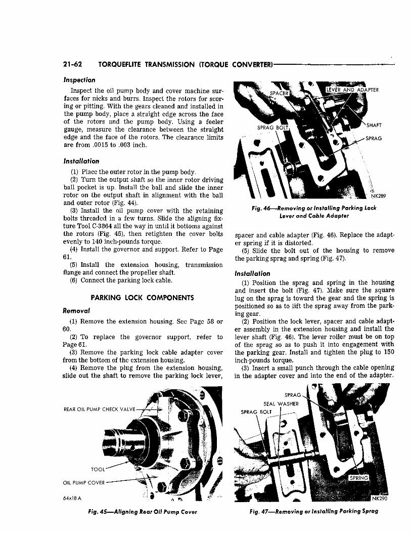
21-62 TORQUEFLITE TRANSMISSION (TORQUE CONVERTER)
Inspection
Inspect the oil pump body and cover machine surfaces for nicks and burrs. Inspect the rotors for scoring or pitting. With the gears cleaned and installed in the pump body, place a straight edge across the face of the rotors and the pump body. Using a feeler gauge, measure the clearance between the straight edge and the face of the rotors. The clearance limits are from .0015 to .003 inch.
Installation
(1) Place the outer rotor in the pump body. (2) Turn the output shaft so the inner rotor driving
ball pocket is up. Install the ball and slide the inner rotor on the output shaft in alignment with the ball and outer rotor (Fig. 44).
(3) Install the oil pump cover with the retaining bolts threaded in a few turns. Slide the aligning fixture Tool C-3864 all the way in until it bottoms against the rotors (Fig. 45), then retighten the cover bolts evenly to 140 inch-pounds torque.
(4) Install the governor and support. Refer to Page 61.
(5) Install the extension housing, transmission flange and connect the propeller shaft.
(6) Connect the parking lock cable.
PARKING LOCK COMPONENTS
Removal
(1) Remove the extension housing. See Page 58 or 60.
(2) To replace the governor support, refer to Page 61.
(3) Remove the parking lock cable adapter cover from the bottom of the extension housing.
(4) Remove the plug from the extension housing, slide out the shaft to remove the parking lock lever,
6 4 x 1 8 A * , -„ %
Fig. 45—Aligning Rear Oil Pump Cover
Fig. 46—Removing or Installing Parking Lock Lever and Cable Adapter
spacer and cable adapter (Fig. 46). Replace the adapter spring if it is distorted.
(5) Slide the bolt out of the housing to remove the parking sprag and spring (Fig. 47).
Installation (1) Position the sprag and spring in the housing
and insert the bolt (Fig. 47). Make sure the square lug on the sprag is toward the gear and the spring is positioned so as to lift the sprag away from the parking gear.
(2) Position the lock lever, spacer and cable adapter assembly in the extension housing and install the lever shaft (Fig. 46). The lever roller must be on top of the sprag so as to push it into engagement with the parking gear. Install and tighten the plug to 150 inch-pounds torque.
(3) Insert a small punch through the cable opening in the adapter cover and into the end of the adapter.
Fig. 47—Removing or Installing Parking Sprag
TORQUEFLITE TRANSMISSION (TORQUE CONVERTER) 21-63
Carefully lower the cover into position, feeding the adapter into the cable opening in the cover. Install the cover retaining screws and tighten to 150 inch-pounds torque.
(4) Install the extension housing, transmission flange and connect the propeller shaft.
(5) Connect and adjust the parking lock cable. See Page 50.
VALVE I O D Y ASSEMBLY AND ACCUMULATOR PISTON
Removal (1) Raise the vehicle on a hoist. (2) Loosen the oil pan bolts, tap the pan to break
it loose allowing the fluid to drain, then remove the oil pan.
(3) Loosen clamp bolt and lift the throttle lever and washer off the transmission throttle lever shaft.
(4) Disconnect the gearshift control cable. Refer to Page 50. Shift the valve body manual lever to the expose the E-clip securing the cable adapter to the lever (Fig. 23). Remove the E-clip and disengage the cable adapter from the manual lever.
(5) Place a drain pan under the transmission, then remove the ten hex-head valve body to transmission case bolts. Hold the valve body in position while removing the bolts.
(6) Lower the valve body assembly down out of the transmission, being careful not to cock the throttle lever shaft in the case hole or lose the accumulator spring.
(7) Withdraw the accumulator piston from the
transmission case. Inspect the piston for scoring, and the rings for wear or breakage. Replace as required.
NOTE: Servicing the valve body assembly is outlined on Page 69.
Removal The transmission and converter must be removed as an assembly; otherwise, the converter drive plate, front pump bushing, and oil seal will be damaged. The drive plate will not support a load; therefore, none of the weight of the transmission should be allowed to rest on the plate during removal.
Removal To remove the transmission on Chrysler Models, it
will be necessary to first remove the torsion bar rear anchor crossmember and rubber isolators. Refer to Group 2, "Torsion Bar Rubber Isolator" for procedures.
(1) Connect a Remote Control Starter Switch, Tool C-763 to the starter solenoid and position the switch so the engine can be rotated from under the vehicle.
(2) Disconnect the secondary (high tension) cable from the ignition coil. Place the selector lever in the PARK position.
(3) Remove the cover plate from in front of the converter assembly to provide access to the converter drain plug and mounting bolts.
Installation (1) Clean mating surfaces and inspect for burrs on
both the transmission case and the valve body steel plate.
(2) Install the accumulator piston in the transmission case.
(3) Position the accumulator spring on the valve body.
(4) Carefully position the valve body assembly in the transmission case, install the retaining bolts and tighten finger tight. With the neutral starting switch installed, place the manual valve in the neutral position. Shift the valve body if necessary to center the neutral finger over the neutral switch plunger. Snug the bolts down evenly, then tighten to 100 inch-pounds torque.
(5) Connect the control cable adapter to the valve body manual lever and install the retaining E-clip. Connect the gearshift control cable. Refer to Page 50.
(6) Install the seal, flat washer and throttle lever on throttle shaft. Tighten the clamping bolt. Test the throttle lever for looseness by forcing it in both directions.
(7) Install the oil pan, using a new gasket. (8) Add fluid to the transmission to bring it up to
proper level. Refer to Page 43.
TRANSMISSION AND CONWERTlt TORQUEFLITE A-727-B
(4) Rotate the engine with the Remote Control Switch to bring the drain plug to the "6 o'clock" position. Drain the torque converter and transmission.
(5) Mark the converter and drive plate to aid in reassembly. The crankshaft flange bolt circle, the inner and outer circle of holes in the drive plate, and the four tapped holes in the front face of the converter all have one hole offset so these parts will be installed in the original position. This maintains the balance of the engine and converter.
(6) Rotate the engine with the Remote Control Switch to locate two converter to drive plate bolts at "5 and 7 o'clock" positions. Remove the two bolts, rotate the engine with the switch and remove the other two bolts. Do not rotate the converter or drive plate by prying with a screw driver or similar tool as the drive plate might become distorted. Also, the starter should never be engaged if the drive plate is not attached to the converter with at least one bolt or if the transmission case to engine block bolts have been loosened.
(7) Disconnect the negative (ground) cable from the battery.
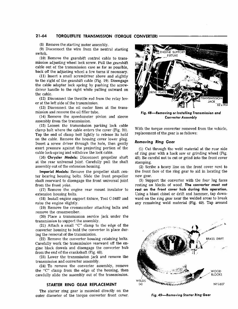
21-64 TORQUEFLITE TRANSMISSION (TORQUE CONVERTER)
(8) Remove the starting motor assembly. ' (9) Disconnect the wire from the neutral starting
switch. (10) Remove the gearshift control cable to trans
mission adjusting wheel lock screw. Pull the gearshift cable out of the transmission case as far as possible, back off the adjusting wheel a few turns if necessary.
(11) Insert a small screwdriver above and slightly to the right of the gearshift cable (Fig. 19). Disengage the cable adapter lock spring by pushing the screwdriver handle to the right while pulling outward on the cable.
(12) Disconnect the throttle rod from the relay lever at the left side of the transmission.
(13) Disconnect the oil cooler lines at the transmission and remove the oil filler tube.
(14) Remove the speedometer pinion and sleeve assembly from the transmission.
(15) Loosen the transmission parking lock cable clamp bolt where the cable enters the cover (Fig. 20). Tap the end of clamp bolt lightly to release its hold on the cable. Remove the housing cover lower plug. Insert a screw driver through the hole, then gently exert pressure against the projecting portion of the cable lock-spring and withdraw the lock cable.
(16) Chrysler Models: Disconnect propeller shaft at the rear universal joint. Carefully pull the shaft assembly out of the extension housing.
Imperial Models: Remove the propeller shaft center bearing housing bolts. Slide the front propeller shaft rearward to disengage the front universal joint from the front yoke.
(17) Remove the engine rear mount insulator to extension housing bolts.
(18) Install engine support fixture, Tool C-3487 and raise the engine slightly.
(19) Remove the crossmember attaching bolts and remove the crossmember.
(20) Place a transmission service jack under the transmission to support the assembly.
(21) Attach a small "C" clamp to the edge of the converter housing to hold the converter in place during the removal of the transmission.
(22) Remove the converter housing retaining bolts. Carefully work the transmission rearward off the engine block dowels and disengage the converter hub from the end of the crankshaft (Fig. 48).
(23) Lower the transmission jack and remove the transmission and converter assembly.
(24) To remove the converter assembly, remove the "C" clamp from the edge of the housing, then carefully slide the assembly out of the transmission.
STARTER RING GEAR REPLACEMENT The starter ring gear is mounted directly on the
outer diameter of the torque converter front cover.
^ E N G I N E S U P P O R T
F I X T U R E
4. /J D R I V E P L A T E
. ? * s&F^ T R A N S M I S S I O N 1 ' y „, ,Zl - f - J A C K
6 2 x 91A
F i g . 48—Removing or Installing Transmission and Converter Assembly
With the torque converter removed from the vehicle, replacement of the gear is as follows:
Removing Ring Gear
(1) Cut through the weld material at the rear side of ring gear with a hack saw or grinding wheel (Fig. 49). Be careful not to cut or grind into the front cover stamping.
(2) Scribe a heavy line on the front cover next to the front face of the ring gear to aid in locating the new gear.
(3) Support the converter with the four lug faces resting on blocks of wood. The converter must not rest on the front cover hub during this operation. Using a blunt chisel or drift and hammer, tap downward on the ring gear near the welded areas to break any remaining weld material (Fig. 49). Tap around
B R A S S D R I F T
W E L D S (4 )
W O O D
B L O C K S
N Y 1 6 0 7
Fig. 49—Removing Starter Ring Gear
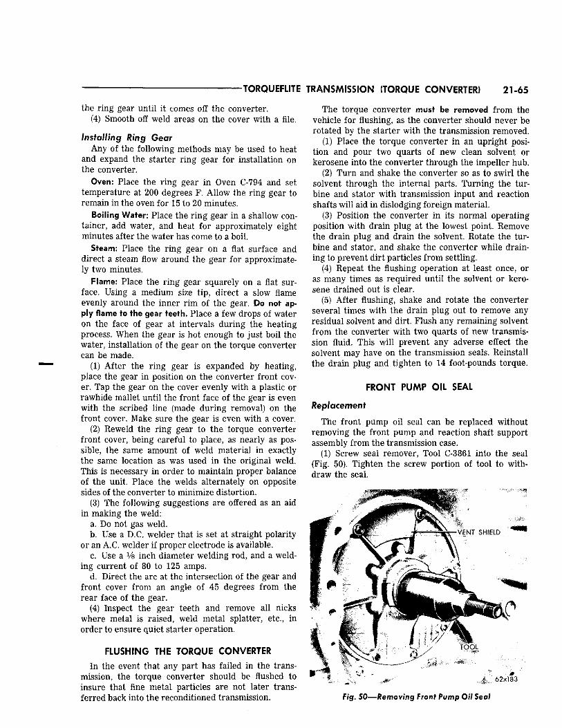
TORQUEFLITE TRANSMISSION (TORQUE CONVERTER) 21-65
the ring gear until it comes off the converter. (4) Smooth off weld areas on the cover with a file.
Installing Ring Gear Any of the following methods may be used to heat
and expand the starter ring gear for installation on the converter.
Oven: Place the ring gear in Oven C-794 and set temperature at 200 degrees F. Allow the ring gear to remain in the oven for 15 to 20 minutes.
Boiling Water: Place the ring gear in a shallow container, add water, and heat for approximately eight minutes after the water has come to a boil.
Steam: Place the ring gear on a flat surface and direct a steam flow around the gear for approximately two minutes.
Flame: Place the ring gear squarely on a flat surface. Using a medium size tip, direct a slow flame evenly around the inner rim of the gear. Do not apply flame to the gear teeth. Place a few drops of water on the face of gear at intervals during the heating process. When the gear is hot enough to just boil the water, installation of the gear on the torque converter can be made.
(1) After the ring gear is expanded by heating, place the gear in position on the converter front cover. Tap the gear on the cover evenly with a plastic or rawhide mallet until the front face of the gear is even with the scribed line (made during removal) on the front cover. Make sure the gear is even with a cover.
(2) Reweld the ring gear to the torque converter front cover, being careful to place, as nearly as possible, the same amount of weld material in exactly the same location as was used in the original weld. This is necessary in order to maintain proper balance of the unit. Place the welds alternately on opposite sides of the converter to minimize distortion.
(3) The following suggestions are offered as an aid in making the weld:
a. Do not gas weld. b. Use a D.C. welder that is set at straight polarity
or an A.C. welder if proper electrode is available. c. Use a Vs inch diameter welding rod, and a weld
ing current of 80 to 125 amps. d. Direct the arc at the intersection of the gear and
front cover from an angle of 45 degrees from the rear face of the gear.
(4) Inspect the gear teeth and remove all nicks where metal is raised, weld metal splatter, etc., in order to ensure quiet starter operation.
FLUSHING THE TORQUE CONVERTER
In the event that any part has failed in the transmission, the torque converter should be flushed to insure that fine metal particles are not later transferred back into the reconditioned transmission.
The torque converter must be removed from the vehicle for flushing, as the converter should never be rotated by the starter with the transmission removed.
(1) Place the torque converter in an upright position and pour two quarts of new clean solvent or kerosene into the converter through the impeller hub.
(2) Turn and shake the converter so as to swirl the solvent through the internal parts. Turning the turbine and stator with transmission input and reaction shafts will aid in dislodging foreign material.
(3) Position the converter in its normal operating position with drain plug at the lowest point. Remove the drain plug and drain the solvent. Rotate the turbine and stator, and shake the converter while draining to prevent dirt particles from settling.
(4) Repeat the flushing operation at least once, or as many times as required until the solvent or kerosene drained out is clear.
(5) After flushing, shake and rotate the converter several times with the drain plug out to remove any residual solvent and dirt. Flush any remaining solvent from the converter with two quarts of new transmission fluid. This will prevent any adverse effect the solvent may have on the transmission seals. Reinstall the drain plug and tighten to 14 foot-pounds torque.
FRONT PUMP OIL SEAL
Replacement
The front pump oil seal can be replaced without removing the front pump and reaction shaft support assembly from the transmission case.
(1) Screw seal remover, Tool C-3861 into the seal (Fig. 50). Tighten the screw portion of tool to withdraw the seal.
6 2 x 1 8 3
F/g. 50—Removing Front Pump Oil Seal
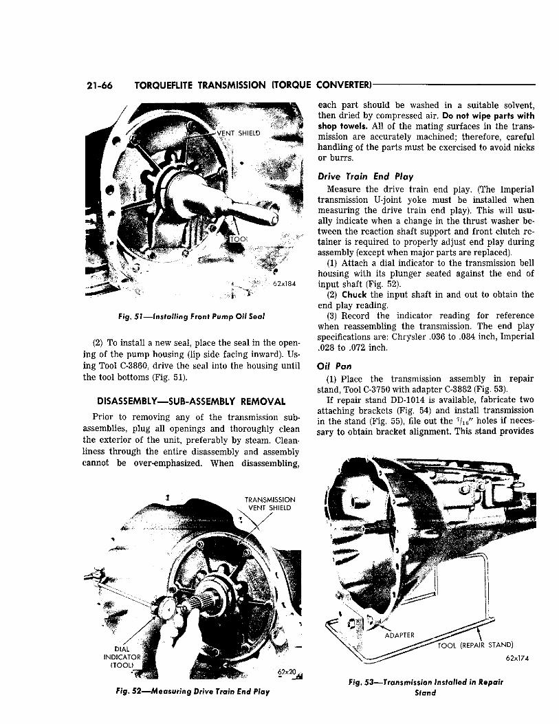
21-66 TORQUEFLITE TRANSMISSION (TORQUE CONVERTER)
Fig, 51— Ins ta l l ing Front Pump Oil Seal
(2) To install a new seal, place the seal in the opening of the pump housing (lip side facing inward). Using Tool C-3860, drive the seal into the housing until the tool bottoms (Fig. 51).
DISASSEMBLY—SUB-ASSEMBLY REMOVAL
Prior to removing any of the transmission subassemblies, plug all openings and thoroughly clean the exterior of the unit, preferably by steam. Cleanliness through the entire disassembly and assembly cannot be over-emphasized. When disassembling,
Fig.. 52—Measuring Drive Train End Play
each part should be washed in a suitable solvent, then dried by compressed air. Do not wipe parts with shop towels. All of the mating surfaces in the transmission are accurately machined; therefore, careful handling of the parts must be exercised to avoid nicks or burrs.
Drive Train End Play Measure the drive train end play. (The Imperial
transmission U-joint yoke must be installed when measuring the drive train end play). This will usually indicate when a change in the thrust washer between the reaction shaft support and front clutch retainer is required to properly adjust end play during assembly (except when major parts are replaced).
(1) Attach a dial indicator to the transmission bell housing with its plunger seated against the end of input shaft (Fig. 52) .
(2) Chuck the input shaft in and out to obtain the end play reading.
(3) Record the indicator reading for reference when reassembling the transmission. The end play specifications are: Chrysler .036 to .084 inch, Imperial .028 to .072 inch.
Oil Pan (1) Place the transmission assembly in repair
stand, Tool C-3750 with adapter C-3882 (Fig. 53). If repair stand DD-1014 is available, fabricate two
attaching brackets (Fig. 54) and install transmission in the stand (Fig. 55), file out the 7 / i 6 " holes if necessary to obtain bracket alignment. This stand provides
6 2 x 1 7 4
F ig . 53—Transmission Installed in Repair Stand
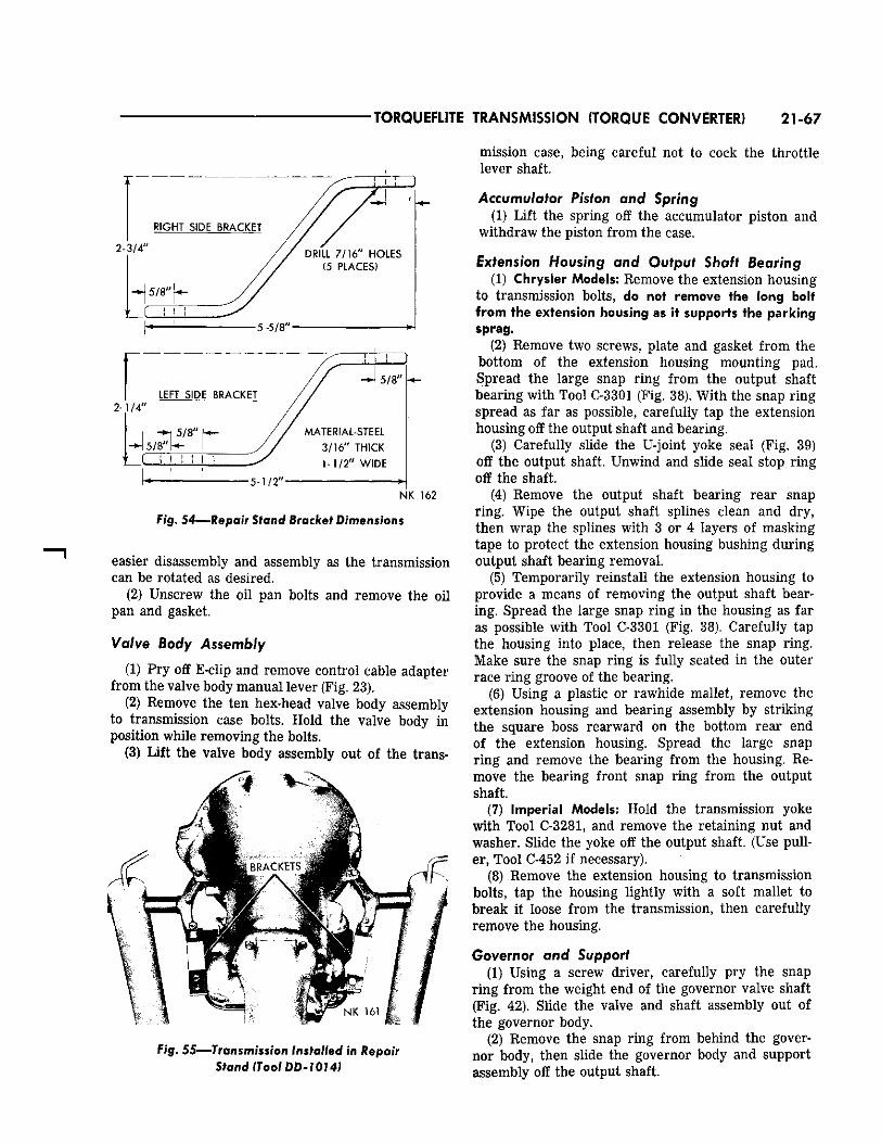
TORQUEFLITE TRANSMISSION (TORQUE CONVERTER) 21-67
N K 1 6 2
Fig. 5 4—Repair Stand Bracket Dimensions
easier disassembly and assembly as the transmission can be rotated as desired.
(2) Unscrew the oil pan bolts and remove the oil pan and gasket.
Valve Body Assembly
(1) Pry off E-clip and remove control cable adapter from the valve body manual lever (Fig. 23).
(2) Remove the ten hex-head valve body assembly to transmission case bolts. Hold the valve body In position while removing the bolts.
(3) Lift the valve body assembly out of the trans-
B R A C K E T S ff^
Fig. 55—Transmission Installed in Repair Stand (Tool DD-1014)
mission case, being careful not to cock the throttle lever shaft.
Accumulator Piston and Spring (1) Lift the spring off the accumulator piston and
withdraw the piston from the case.
Extension Housing and Output Shaft Bearing (1) Chrysler Models: Remove the extension housing
to transmission bolts, do not remove the long bolt from the extension housing as it supports the parking sprag.
(2) Remove two screws, plate and gasket from the bottom of the extension housing mounting pad. Spread the large snap ring from the output shaft bearing with Tool C-3301 (Fig. 38). With the snap ring spread as far as possible, carefully tap the extension housing off the output shaft and bearing.
(3) Carefully slide the U-joint yoke seal (Fig. 39) off the output shaft. Unwind and slide seal stop ring off the shaft.
(4) Remove the output shaft bearing rear snap ring. Wipe the output shaft splines clean and dry, then wrap the splines with 3 or 4 layers of masking tape to protect the extension housing bushing during output shaft bearing removal.
(5) Temporarily reinstall the extension housing to provide a means of removing the output shaft bearing. Spread the large snap ring in the housing as far as possible with Tool C-3301 (Fig. 38). Carefully tap the housing into place, then release the snap ring. Make sure the snap ring is fully seated in the outer race ring groove of the bearing.
(6) Using a plastic or rawhide mallet, remove the extension housing and bearing assembly by striking the square boss rearward on the bottom rear end of the extension housing. Spread the large snap ring and remove the bearing from the housing. Remove the bearing front snap ring from the output shaft.
(7) Imperial Models: Hold the transmission yoke with Tool C-3281, and remove the retaining nut and washer. Slide the yoke off the output shaft. (Use puller, Tool C-452 if necessary).
(8) Remove the extension housing to transmission bolts, tap the housing lightly with a soft mallet to break it loose from the transmission, then carefully remove the housing.
Governor and Support (1) Using a screw driver, carefully pry the snap
ring from the weight end of the governor valve shaft (Fig. 42). Slide the valve and shaft assembly out of the governor body.
(2) Remove the snap ring from behind the governor body, then slide the governor body and support assembly off the output shaft.
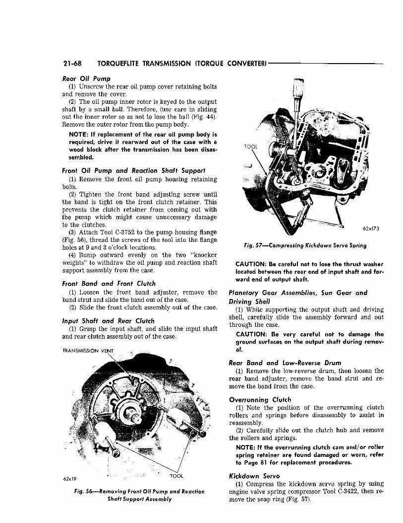
21 -68 TORQUEFLITE TRANSMISSION (TORQUE CONVERTER)
Rear Oil Pump (1) Unscrew the rear oil pump cover retaining bolts
and remove the cover. (2) The oil pump inner rotor is keyed to the output
shaft by a small ball. Therefore, (use care in sliding out the inner rotor so as not to lose the ball (Fig. 44). Remove the outer rotor from the pump body.
NOTE: If replacement of the rear oil pump body is required, drive it rearward out of the case with a wood block after the transmission has been disassembled.
Front Oil Pump and Reaction Shaft Support (1) Remove the front oil pump housing retaining
bolts. (2) Tighten the front band adjusting screw until
the band is tight on the front clutch retainer. This prevents the clutch retainer from coming out with the pump which might cause unnecessary damage to the clutches.
(3) Attach Tool C-3752 to the pump housing flange (Fig. 56), thread the screws of the tool into the flange holes at 9 and 3 o'clock locations.
(4) Bump outward evenly on the two "knocker weights" to withdraw the oil pump and reaction shaft support assembly from the case.
Front Band and Front Clutch (1) Loosen the front band adjuster, remove the
band strut and slide the band out of the case. (2) Slide the front clutch assembly out of the case.
Input Shaft and Rear Clutch (1) Grasp the input shaft, and slide the input shaft
and rear clutch assembly out of the case.
T R A N S M I S S I O N V E N T
Fig. 56—Removing Front Oil Pump and Reaction Shaft Support Assembly
Fig. 57—Compressing Kickdown Servo Spring
CAUTION: Be careful not to lose the thrust washer located between the rear end of input shaft and forward end of output shaft.
Planetary Gear Assemblies, Sun Gear and Driving Shell
(1) While supporting the output shaft and driving shell, carefully slide the assembly forward and out through the case.
CAUTION: Be very careful not to damage the ground surfaces on the output shaft during removal.
Rear Band and Low-Reverse Drum (1) Remove the low-reverse drum, then loosen the
rear band adjuster, remove the band strut and remove the band from the case.
Overrunning Clutch (1) Note the position of the overrunning clutch
rollers and springs before disassembly to assist in reassembly.
(2) Carefully slide out the clutch hub and remove the rollers and springs.
NOTE: If the overrunning clutch cam and/or roller spring retainer are found damaged or worn, refer to Page 81 for replacement procedures.
Kickdown Servo (1) Compress the kickdown servo spring by using
engine valve spring compressor Tool C-3422, then remove the snap ring (Fig. 57).
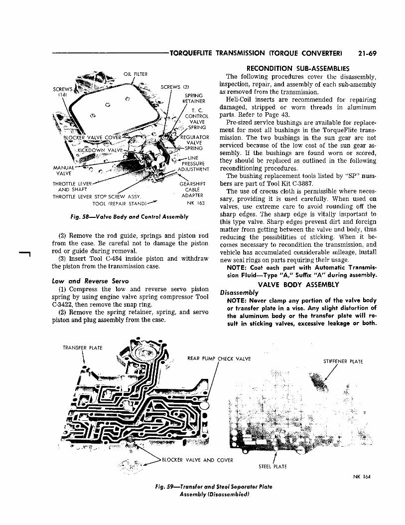
TORQUEFLITE TRANSMISSION (TORQUE CONVERTER) 21-69
S C R E W S , (14 )
T . C . C O N T R O L
V A L V E
THROTTLE L E V E R -
A N D S H A F T
THROTTLE LEVER S T O P S C R E W A S S Y .
TOOL (REPAIR STAND)-
L INE P R E S S U R E
^ A D J U S T M E N T
X G E A R S H I F T
C A B L E A D A P T E R
NK 163
F ig . 58—Valve Body and Control Assembly
(2) Remove the rod guide, springs and piston rod from the case. Be careful not to damage the piston rod or guide during removal.
(3) Insert Tool C-484 inside piston and withdraw the piston from the transmission case.
Low and Reverse Servo (1) Compress the low and reverse servo piston
spring by using engine valve spring compressor Tool C-3422, then remove the snap ring.
(2) Remove the spring retainer, spring, and servo piston and plug assembly from the case.
RECONDITION SUB-ASSEMBLIES The following procedures cover the disassembly,
inspection, repair, and assembly of each sub-assembly as removed from the transmission.
Heli-Coil inserts are recommended for repairing damaged, stripped or worn threads in aluminum parts. Refer to Page 43.
Pre-sized service bushings are available for replacement for most all bushings in the TorqueFlite transmission. The two bushings in the sun gear are not serviced because of the low cost of the sun gear assembly. If the bushings are found worn or scored, they should be replaced as outlined in the following reconditioning procedures.
The bushing replacement tools listed by "SP" numbers are part of Tool Kit C-3887.
The use of crocus cloth is permissible where necessary, providing it is used carefully. When used on valves, use extreme care to avoid rounding off the sharp edges. The sharp edge is vitally important to this type valve. Sharp edges prevent dirt and foreign matter from getting between the valve and body, thus reducing the possibilities of sticking. When it becomes necessary to recondition the transmission, and vehicle has accumulated considerable mileage, install new seal rings on parts requiring their usage.
NOTE: Coat each part with Automatic Transmission Fluid—Type "A," Suffix "A" during assembly.
VALVE BODY ASSEMBLY Disassembly
NOTE: Never clamp any portion of the valve body or transfer plate in a vise. Any slight distortion of the aluminum body or the transfer plate will result in sticking valves, excessive leakage or both.
N K 164
F ig . 59—Transfer and Steel Separater Plate Assembly (Disassembled)
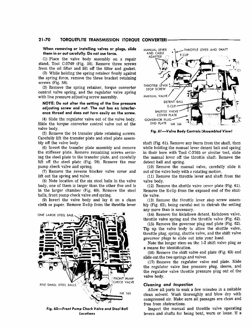
21-70 TORQUEFLITE TRANSMISSION (TORQUE CONVERTER)
When removing or installing valves or plugs, slide them in or out carefully. Do not use force. (1) Place the valve body assembly on a repair
stand, Tool C-3749 (Fig. 58). Remove three screws from the oil filter and lift off the filter and gasket.
(2) While holding the spring retainer firmly against the spring force, remove the three bracket retaining screws (Fig. 58).
(3) Remove the spring retainer, torque converter control valve spring, and the regulator valve spring with line pressure adjusting screw assembly.
N O T E : Do not alter the setting of the line pressure adjusting screw and nut. T h e nut has an interference thread and does not turn easily on the screw.
(4) Slide the regulator valve out of the valve body. Slide the torque converter control valve out of the valve body.
(5) Remove the 14 transfer plate retaining screws. Carefully lift the transfer plate and steel plate assembly off the valve body.
(6) Invert the transfer plate assembly and remove the stiffener plate. Remove remaining screws securing the steel plate to the transfer plate, and carefully lift off the steel plate (Fig. 59). Remove the rear pump check valve and spring.
(7) Remove the reverse blocker valve cover and lift out the spring and valve.
(8) Note location of the six steel balls in the valve body, one of them is larger than the other five and is in the larger chamber (Fig. 60). Remove the steel balls, front pump check valve and spring.
(9) Invert the valve body and lay it on a clean cloth or paper. Remove E-clip from the throttle lever
O N E L A R G E S T E E L B A L L
M A N U A L L E V E R T H R O T T L E L E V E R A N D S H A F T A N D C A B L E 4
A D A P T E R \
F I V E S M A L L S T E E L B A L L S LRW!|R' F R O N T P U M P
C H E C K V A L V E
F i g . 6 0 — F r o n f Pump C h e c k Valve and Steel Ball Locations
T H R O T T L E L E V E R V
S T O P S C R E W
M A N U A L V A L V E
D E T E N T "
E - C L I P
S H U T T L E V A L V E
C O V E R P L A T E
G O V E R N O R P L U G E N D P L A T E N K 1 6 6
F i g . 61—Valve Body Controls (Assembled View)
shaft (Fig. 61). Remove any burrs from the shaft, then while holding the manual lever detent ball and spring in their bore with Tool C-3765 or similar tool, slide the manual lever off the throttle shaft. Remove the detent ball and spring.
(10) Remove the manual valve, carefully slide it out of the valve body with a rotating motion.
(11) Remove the throttle lever and shaft from the valve body.
(12) Remove the shuttle valve cover plate (Fig. 61). Remove the E-clip from the exposed end of the shuttle valve.
(13) Remove the throttle lever stop screw assembly (Fig. 62), being careful not to distrub the setting any more than is necessary.
(14) Remove the kickdown detent, kickdown valve, throttle valve spring and the throttle valve (Fig. 62).
(15) Remove the governor plug end plate (Fig. 62). Tip up the valve body to allow the shuttle valve, throttle plug, spring, shuttle valve, and the shift valve governor plugs to slide out into your hand.
Note the longer stem on the 1-2 shift valve plug as a means for identification.
(16) Remove the shift valve end plate (Fig. 63) and slide out the two springs and valves.
(17) Remove the regulator valve end plate. Slide the regulator valve line pressure plug, sleeve, and the regulator valve throttle pressure plug out of the valve body.
Cleaning and Inspection Allow all parts to soak a few minutes in a suitable
clean solvent. Wash thoroughly and blow dry with compressed air. Make sure all passages are clean and free from obstructions.
Inspect the manual and throttle valve operating levers and shafts for being bent, worn or loose. If a
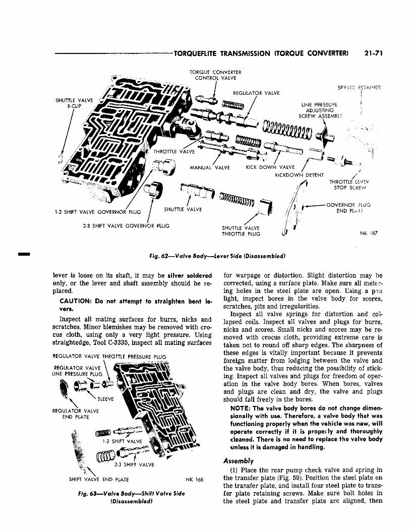
TORQUEFLITE TRANSMISSION (TORQUE CONVERTER) 21-71
T O R Q U E C O N V E R T E R
T H R O T T L E P L U G NK 1 6 7
F i g . 62—Valve Body—Lever Side (Disassembled)
lever is loose on its shaft, it may be silver soldered only, or the lever and shaft assembly should be replaced.
CAUTION: Do not attempt to straighten bent levers.
Inspect all mating surfaces for burrs, nicks and scratches. Minor blemishes may be removed with crocus cloth, using only a very light pressure. Using straightedge, Tool C-3335, inspect all mating surfaces
R E G U L A T O R V A L V E T H R O T T L E P R E S S U R E P L U G
S H I F T V A L V E E N D P L A T E N K 1 6 8
Fig. 63—Valve Body—Shift Valve Side (Disassembled)
for warpage or distortion. Slight distortion may be corrected, using a surface plate. Make sure all metering holes in the steel plate are open. Using a pen light, inspect bores in the valve body for scores, scratches, pits and irregularities.
Inspect all valve springs for distortion and collapsed coils. Inspect all valves and plugs for burrs, nicks and scores. Small nicks and scores may be removed with crocus cloth, providing extreme care is taken not to round off sharp edges. The sharpness of these edges is vitally important because it prevents foreign matter from lodging between the valve and the valve body, thus reducing the possibility of sticking. Inspect all valves and plugs for freedom of operation in the valve body bores. When bores, valves and plugs are clean and dry, the valve and plugs should fall freely in the bores.
NOTE: The valve body bores do not change dimen-sionally with use. Therefore, a valve body that was functioning properly when the vehicle was new, will operate correctly if it is properly and thoroughly cleaned. There is no need to replace the valve body unless it is damaged in handling.
Assembly (1) Place the rear pump check valve and spring in
the transfer plate (Fig. 59). Position the steel plate on the transfer plate, and install four steel plate to transfer plate retaining screws. Make sure bolt holes in the steel plate and transfer plate are aligned, then
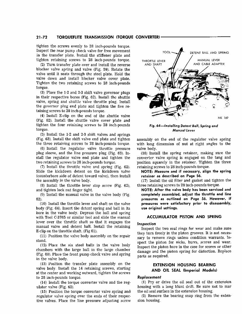
21-72 TORQUEFLITE TRANSMISSION (TORQUE CONVERTER)
tighten the screws evenly to 28 inch-pounds torque. Inspect the rear pump check valve for free movement in the transfer plate. Install the stiffener plate and tighten retaining screws to 28 inch-pounds torque.
(2) Turn transfer plate over and install the reverse blocker valve spring and valve (Fig. 59). Rotate the valve until it seats through the steel plate. Hold the valve down and install blocker valve cover plate. Tighten the two retaining screws to 28 inch-pounds torque.
(3) Place the 1-2 and 2-3 shift valve governor plugs in their respective bores (Fig. 62). Install the shuttle valve, spring and shuttle valve throttle plug. Install the governor plug end plate and tighten the five retaining screws to 28 inch-pounds torque.
(4) Install E-clip on the end of the shuttle valve (Fig. 62). Install the shuttle valve cover plate and tighten the four retaining screws to 28 inch-pounds torque.
(5) Install the 1-2 and 2-3 shift valves and springs (Fig. 63). Install the shift valve end plate and tighten the three retaining screws to 28 inch-pounds torque.
(6) Install the regulator valve throttle pressure plug sleeve, and the line pressure plug (Fig. 63). Install the regulator valve end plate and tighten the two retaining screws to 28 inch-pounds torque.
(7) Install the throttle valve and spring (Fig. 62). Slide the kickdown detent on the kickdown valve (counterbore side of detent toward valve), then install the assembly in the valve body.
(8) Install the throttle lever stop screw (Fig. 62), and tighten lock nut finger tight.
(9) Install the manual valve in the valve body (Fig. 62).
(10) Install the throttle lever and shaft on the valve body (Fig. 64). Insert the detent spring and ball in its bore in the valve body. Depress the ball and spring with Tool C-3765 or similar tool and slide the manual lever over the throttle shaft so that it engages the manual valve and detent ball. Install the retaining E-clip on the throttle shaft. (Fig 61).
(11) Position the valve body assembly on the repair stand.
(12) Place the six steel balls in the valve body chambers with the large ball in the large chamber (Fig. 60). Place the front pump check valve and spring in the valve body.
(13) Position the transfer plate assembly on the valve body. Install the 14 retaining screws, starting at the center and working outward, tighten the screws to 28 inch-pounds torque.
(14) Install the torque converter valve and the regulator valve (Fig. 62).
(15) Position the torque converter valve spring and regulator valve spring over the ends of their respective valves. Place the line pressure adjusting screw
N K 1 6 9
F ig . 64—Installing Detent Ball, Spring and Manual Lever
assembly on the end of the regulator valve spring with long dimension of nut at right angles to the valve body.
(16) Install the spring retainer, making sure the converter valve spring is engaged on the tang and position squarely in the retainer. Tighten the three retaining screws to 28 inch-pounds torque.
NOTE; Measure and if necessary, align the spring retainer as described on Page 56. (17) Install the oil filter and gasket and tighten the
three retaining screws to 28 inch-pounds torque. NOTE; After the valve body has been serviced and completely assembled, adjust the throttle and line pressures as outlined on Page 56. However, if pressures were satisfactory prior to disassembly, use original settings.
ACCUMULATOR PISTON AND SPRING
Inspection Inspect the two seal rings for wear and make sure
they turn freely in the piston grooves. It is not necessary to remove rings unless condition warrants. Inspect the piston for nicks, burrs, scores and wear. Inspect the piston bore in the case for scores or other damage and the piston spring for distortion. Replace parts as required.
EXTENSION HOUSING BEARING AND OIL SEAL (Imperial Models)
Replacement (1) Pry or drive the oil seal out of the extension
housing with a long blunt drift. Be sure not to mar the oil seal surface in the extension housing.
(2) Remove the bearing snap ring from the extension housing.
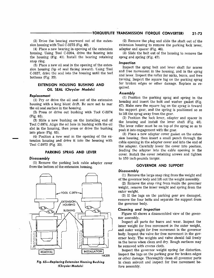
•TORQUEFLITE TRANSMISSION (TORQUE CONVERTER) 21-73
(3) Drive the bearing rearward out of the extension housing with Tool C-3275 (Fig. 40).
(4) Place a new bearing in opening of the extension housing. Using Tool C-3204, drive the bearing into the housing (Fig. 41). Install the bearing retaining snap ring.
(5) Place a new oil seal in the opening of the extension housing (lip of seal facing inward). Using Tool C-3837, drive the seal into the housing until the tool bottoms (Fig. 35).
EXTENSION HOUSING BUSHING AND OIL SEAL (Chrysler Models)
Replacement (1) Pry or drive the oil seal out of the extension
housing with a long blunt drift. Be sure not to mar the oil seal surface in the housing.
(2) Press or drive out bushing with Tool C-3974 (Fig. 65).
(3) Slide a new bushing on the installing end of Tool C-3974. Align the oil hole in bushing with the oil slot in the housing, then press or drive the bushing into place (Fig. 65).
(4) Position a new seal in the opening of the extension housing and drive it into the housing with Tool C-3972 (Fig. 35).
PARKING SPRAG AND LEVER
Disassembly (1) Remove the parking lock cable adapter cover
from the bottom of the extension housing.
NK308
Fig. 65—Replacing Extension Housing Bushing (Chrysler Models)
(2) Remove the plug and slide the shaft out of the extension housing to remove the parking lock lever, adapter and spacer (Fig. 46).
(3) Slide the bolt out of the housing to remove the sprag and spring (Fig. 47). Inspection
Inspect the sprag bolt and lever shaft for scores and free movement in the housing, and in the sprag and lever. Inspect the roller for nicks, burrs, and free turning. Inspect the square lug on the parking sprag for broken edges or other damage. Replace as required.
Assembly (1) Position the parking sprag and spring in the
housing and insert the bolt and washer gasket (Fig. 47). Make sure the square lug on the sprag is toward the support gear, and the spring is positioned so as to lift the sprag away from the gear.
(2) Position the lock lever, adapter and spacer in the housing and install the lever shaft (Fig. 46). The lever roller must be on top of the sprag so as to push it into engagement with the gear.
(3) Place a new adapter cover gasket on the extension housing, then insert a small punch through the cable opening in the adapter cover and into the end of the adapter. Carefully lower the cover into position, feeding the adapter into the cable opening in the cover. Install the cover retaining screws and tighten to 150 inch-pounds torque.
GOVERNOR AND SUPPORT Disassembly
(1) Remove the large snap ring from the weight end of the governor body and lift out the weight assembly.
(2) Remove the snap ring from inside the governor weight, remove the inner weight and spring from the outer weight.
(3) If the lugs on the parking gear are damaged, remove the four bolts and separate the support from the governor body.
Cleaning and Inspection Figure 43 shows a disassembled view of the gover
nor assembly. Inspect all parts for burrs and wear. Inspect the
inner weight for free movement in the outer weight, and outer weight for free movement in the governor body. Inspect the valve for free movement in the governor body. The weights and valve should fall freely in the bores when clean and dry. Rough surfaces may be removed with crocus cloth.
Inspect the governor weight spring for distortion. Inspect the lugs on the parking gear for broken edges or other damage. Thoroughly clean all governor parts in clean solvent and inspect for free movement before assembly.
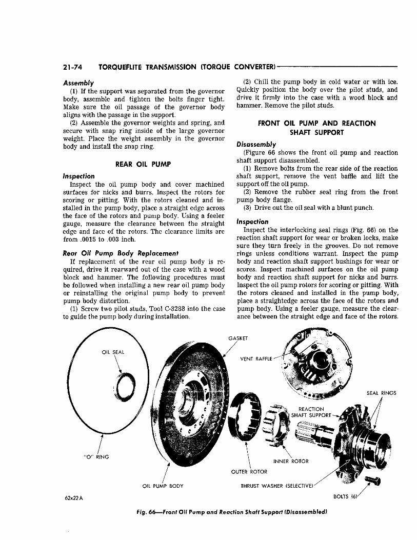
21-74 TORQUEFLITE TRANSMISSION (TORQUE CONVERTER)
Assembly (1) If the support was separated from the governor
body, assemble and tighten the bolts finger tight. Make sure the oil passage of the governor body aligns with the passage in the support.
(2) Assemble the governor weights and spring, and secure with snap ring inside of the large governor weight. Place the weight assembly in the governor body and Install the snap ring.
REAR OIL PUMP
Inspection Inspect the oil pump body and cover machined
surfaces for nicks and burrs. Inspect the rotors for scoring or pitting. With the rotors cleaned and installed in the pump body, place a straight edge across the face of the rotors and pump body. Using a feeler gauge, measure the clearance between the straight edge and face of the rotors. The clearance limits are from .0015 to .003 inch.
Rear OH Pump Body Replacement If replacement of the rear oil pump body Is re
quired, drive it rearward out of the case with a wood block and hammer. The following procedures must be followed when installing a new rear oil pump body or reinstalling the original pump body to prevent pump body distortion.
(1) Screw two pilot studs, Tool C-3288 into the case to guide the pump body during installation.
(2) Chill the pump body in cold water or with ice. Quickly position the body over the pilot studs, and drive it firmly into the case with a wood block and hammer. Remove the pilot studs.
FRONT OIL PUMP AND REACTION SHAFT SUPPORT
Disassembly (Figure 66 shows the front oil pump and reaction
shaft support disassembled. (1) Remove bolts from the rear side of the reaction
shaft support, remove the vent baffle and lift the support off the oil pump.
(2) Remove the rubber seal ring from the front pump body flange.
(3) Drive out the oil seal with a blunt punch.
Inspection Inspect the interlocking seal rings (Fig. 66) on the
reaction shaft support for wear or broken locks, make sure they turn freely in the grooves. Do not remove rings unless conditions warrant. Inspect the pump body and reaction shaft support bushings for wear or scores. Inspect machined surfaces on the oil pump body and reaction shaft support for nicks and burrs. Inspect the oil pump rotors for scoring or pitting. With the rotors cleaned and installed in the pump body, place a straightedge across the face of the rotors and pump body. Using a feeler gauge, measure the clearance between the straight edge and face of the rotors.
G A S K E T
" O " R I N G
V E N T B A F F L E
S E A L R I N G S
R E A C T I O N
v % S H A F T S U P P O R T
I N N E R R O T O R
O I L P U M P B O D Y
O U T E R R O T O R
T H R U S T W A S H E R ( S E L E C T I V E )
62x22 jk B O L T S (6K
Fig. 66—Front Oil Pump and Reaction Shaft Support (Disassembled)
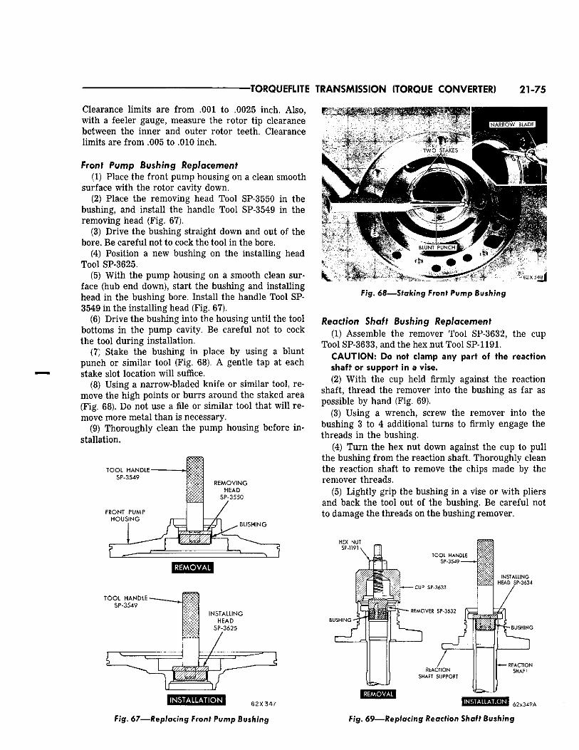
•TORQUEFLITE TRANSMISSION (TORQUE CONVERTER} 21-75
Clearance limits are from .001 to .0025 inch. Also, with a feeler gauge, measure the rotor tip clearance between the inner and outer rotor teeth. Clearance limits are from .005 to .010 inch.
front Pump Bushing Replacement (1) Place the front pump housing on a clean smooth
surface with the rotor cavity down. (2) Place the removing head Tool SP-3550 in the
bushing, and install the handle Tool SP-3549 in the removing head (Fig. 67).
(3) Drive the bushing straight down and out of the bore. Be careful not to cock the tool in the bore.
(4) Position a new bushing on the installing head Tool SP-3625.
(5) With the pump housing on a smooth clean surface (hub end down), start the bushing and installing head in the bushing bore. Install the handle Tool SP-3549 in the installing head (Fig. 67).
(6) Drive the bushing into the housing until the tool bottoms in the pump cavity. Be careful not to cock the tool during installation.
(7) Stake the bushing in place by using a blunt punch or similar tool (Fig. 68). A gentle tap at each stake slot location will suffice.
(8) Using a narrow-bladed knife or similar tool, remove the high points or burrs around the staked area (Fig. 68). Do not use a file or similar tool that will remove more metal than is necessary.
(9) Thoroughly clean the pump housing before installation.
T O O L HANDLE SP-3549
FRONT PUMP HOUSING
REMOVAL
T O O L HANDLE SP-3549
I N S T A L L A T I O N 6 2 X 3 4 7
F i g . 6 7 — R e p l a c i n g Front Pump Bushing
Fig. 68—-Staking Front Pump Bushing
Reaction Shaft Bushing Replacement (1) Assemble the remover Tool SP-3632, the cup
Tool SP-3633, and the hex nut Tool SP-1191. CAUTION: Do not clamp any part of the reaction shaft or support in a vise. (2) With the cup held firmly against the reaction
shaft, thread the remover into the bushing as far as possible by hand (Fig. 69).
(3) Using a wrench, screw the remover into the bushing 3 to 4 additional turns to firmly engage the threads in the bushing.
(4) Turn the hex nut down against the cup to pull the bushing from the reaction shaft. Thoroughly clean the reaction shaft to remove the chips made by the remover threads.
(5) Lightly grip the bushing in a vise or with pliers and back the tool out of the bushing. Be careful not to damage the threads on the bushing remover.
HEX NUT SP-1191
INSTALLING HEAD SP-3634
BUSHING
I N S T A L L A T I O N
Fig. 69—Replacing Reaction Shaft Bushing
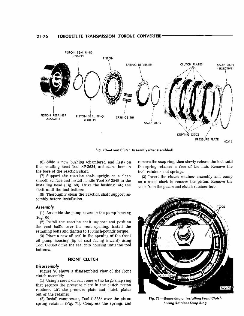
21-76 TORQUEFLITE TRANSMISSION (TORQUE CONVERTER)
P I S T O N S E A L R I N G
P R E S S U R E P L A T E
Fig. 70—Front Clutch Assembly (Disassembled)
(6) Slide a new bushing (chamfered end first) on the installing head Tool SP-3634, and start them in the bore of the reaction shaft.
(7) Support the reaction shaft upright on a clean smooth surface and install handle Tool SP-3549 in the installing head (Fig. 69). Drive the bushing into the shaft until the tool bottoms.
(8) Thoroughly clean the reaction shaft support assembly before installation.
Assembly (1) Assemble the pump rotors in the pump housing
(Fig. 66). (2) Install the reaction shaft support and position
the vent baffle over the vent opening. Install the retaining bolts and tighten to 150 inch-pounds torque.
(3) Place a new oil seal in the opening of the front oil pump housing (lip of seal facing inward) using Tool C-3860 drive the seal into housing until the tool bottoms.
FRONT CLUTCH
Disassembly Figure 70 shows a disassembled view of the front
clutch assembly. (1) Using a screw driver, remove the large snap ring
that secures the pressure plate in the clutch piston retainer. Lift the pressure plate and clutch plates out of the retainer.
(2) Install compressor, Tool C-3863 over the piston spring retainer (Fig. 71). Compress the springs and
remove the snap ring, then slowly release the tool until the spring retainer is free of the hub. Remove the tool, retainer and springs.
(3) Invert the clutch retainer assembly and bump on a wood block to remove the piston. Remove the seals from the piston and clutch retainer hub.
Fig. 71—Removing or Installing Front Clutch Spring Retainer Snap Ring
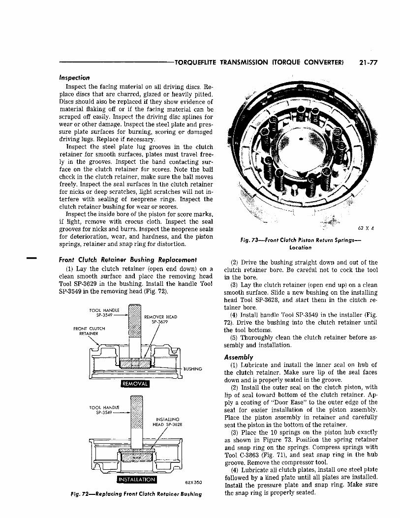
TORQUEFLITE TRANSMISSION (TORQUE CONVERTER) 21-77
Inspection Inspect the facing material on all driving discs. Re
place discs that are charred, glazed or heavily pitted. Discs should also be replaced if they show evidence of material flaking off or if the facing material can be scraped off easily. Inspect the driving disc splines for wear or other damage. Inspect the steel plate and pressure plate surfaces for burning, scoring or damaged driving lugs. Replace if necessary.
Inspect the steel plate lug grooves in the clutch retainer for smooth surfaces, plates must travel freely in the grooves. Inspect the band contacting surface on the clutch retainer for scores. Note the ball check in the clutch retainer, make sure the ball moves freely. Inspect the seal surfaces in the clutch retainer for nicks or deep scratches, light scratches will not interfere with sealing of neoprene rings. Inspect the clutch retainer bushing for wear or scores.
Inspect the inside bore of the piston for score marks, if light, remove with crocus cloth. Inspect the seal grooves for nicks and burrs. Inspect the neoprene seals for deterioration, wear, and hardness, and the piston springs, retainer and snap ring for distortion.
Front Clutch Retainer Bushing Replacement (1) Lay the clutch retainer (open end down) on a
clean smooth surface and place the removing head Tool SP-3629 in the bushing. Install the handle Tool SP-3549 in the removing head (Fig. 72).
B U S H I N G
mkmmMmmdm 62x350
Fig . 7 2 — R e p l a c i n g Front Clutch Retainer Bushing
Fig. 73—Front Clutch Piston Return Springs— Location
(2) Drive the bushing straight down and out of the clutch retainer bore. Be careful not to cock the tool in the bore.
(3) Lay the clutch retainer (open end up) on a clean smooth surface. Slide a new bushing on the installing head Tool SP-3628, and start them in the clutch retainer bore.
(4) Install handle Tool SP-3549 in the installer (Fig. 72). Drive the bushing into the clutch retainer until the tool bottoms.
(5) Thoroughly clean the clutch retainer before assembly and installation.
Assembly (1) Lubricate and install the inner seal on hub of
the clutch retainer. Make sure lip of the seal faces down and is properly seated in the groove.
(2) Install the outer seal on the clutch piston, with lip of seal toward bottom of the clutch retainer. Apply a coating of "Door Ease" to the outer edge of the seal for easier installation of the piston assembly. Place the piston assembly in retainer and carefully seat the piston in the bottom of the retainer.
(3) Place the 10 springs on the piston hub exactly as shown in Figure 73. Position the spring retainer and snap ring on the springs. Compress springs with Tool C-3863 (Fig. 71), and seat snap ring in the hub groove. Remove the compressor tool.
(4) Lubricate all clutch plates, install one steel plate followed by a lined plate until all plates are installed. Install the pressure plate and snap ring. Make sure the snap ring is properly seated.
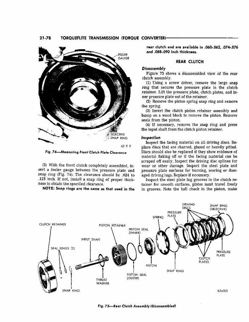
21-78 TORQUEFLITE TRANSMISSION (TORQUE CONVERTER)
62 X 2
Fig. 74—Measuring Front Clutch Plate Clearance
(5) With the front clutch completely assembled, insert a feeler gauge between the pressure plate and snap ring (Fig. 74). The clearance should be .024 to 123 inch. If not, install a snap ring of proper thick
ness to obtain the specified clearance. NOTE: Snap rings are the same as that used in the
rear clutch and are available in .060-.062, .074-.076 and .088-.090 inch thickness.
REAR CLUTCH
Disassembly Figure 75 shows a disassembled view of the rear
clutch assembly. (1) Using a screw driver, remove the large snap
ring that secures the pressure plate in the clutch retainer. Lift the pressure plate, clutch plates, and inner pressure plate out of the retainer.
(2) Remove the piston spring snap ring and remove the spring,
(3) Invert the clutch piston retainer assembly and bump on a wood block to remove the piston. Remove seals from the piston.
(4) If necessary, remove the snap ring and press the input shaft from the clutch piston retainer.
Inspection Inspect the facing material on all driving discs. Re
place discs that are charred, glazed or heavily pitted. Discs should also be replaced if they show evidence of material flaking off or if the facing material can be scraped off easily. Inspect the driving disc splines for wear or other damage. Inspect the steel plate and pressure plate surfaces for burning, scoring or damaged driving lugs. Replace if necessary.
Inspect the steel plate lug grooves in the clutch retainer for smooth surfaces, plates must travel freely in grooves. Note the ball check in the piston, make
F ig . 7 5 — R e a r Clutch Assembly (Disassembled)
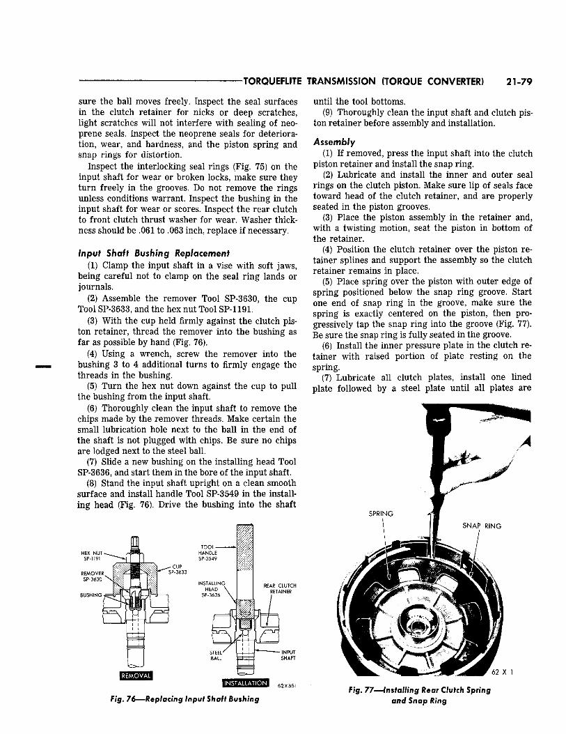
TORQUEFLITE TRANSMISSION (TORQUE CONVERTER) 21-79
sure the ball moves freely. Inspect the seal surfaces in the clutch retainer for nicks or deep scratches, light scratches will not interfere with sealing of neoprene seals. Inspect the neoprene seals for deterioration, wear, and hardness, and the piston spring and snap rings for distortion.
Inspect the interlocking seal rings (Fig. 75) on the input shaft for wear or broken locks, make sure they turn freely in the grooves. Do not remove the rings unless conditions warrant. Inspect the bushing in the input shaft for wear or scores. Inspect the rear clutch to front clutch thrust washer for wear. Washer thickness should be .061 to .063 inch, replace if necessary.
Input Shaft lushing Replacement (1) Clamp the input shaft in a vise with soft jaws,
being careful not to clamp on the seal ring lands or journals.
(2) Assemble the remover Tool SP-3630, the cup Tool SP-3633, and the hex nut Tool SP-1191.
(3) With the cup held firmly against the clutch piston retainer, thread the remover into the bushing as far as possible by hand (Fig. 76).
(4) Using a wrench, screw the remover into the bushing 3 to 4 additional turns to firmly engage the threads in the bushing.
(5) Turn the hex nut down against the cup to pull the bushing from the input shaft.
(6) Thoroughly clean the input shaft to remove the chips made by the remover threads. Make certain the small lubrication hole next to the ball in the end of the shaft is not plugged with chips. Be sure no chips are lodged next to the steel ball.
(7) Slide a new bushing on the installing head Tool SP-3636, and start them in the bore of the input shaft.
(8) Stand the input shaft upright on a clean smooth surface and install handle Tool SP-3549 in the installing head (Fig. 76). Drive the bushing into the shaft
62X351
Fig. 76—Replacing input Shaft Bushing
until the tool bottoms. (9) Thoroughly clean the input shaft and clutch pis
ton retainer before assembly and installation.
Assembly (1) If removed, press the input shaft into the clutch
piston retainer and install the snap ring. (2) Lubricate and install the inner and outer seal
rings on the clutch piston. Make sure lip of seals face toward head of the clutch retainer, and are properly seated in the piston grooves.
(3) Place the piston assembly in the retainer and, with a twisting motion, seat the piston in bottom of the retainer.
(4) Position the clutch retainer over the piston retainer splines and support the assembly so the clutch retainer remains in place.
(5) Place spring over the piston with outer edge of spring positioned below the snap ring groove. Start one end of snap ring in the groove, make sure the spring Is exactly centered on the piston, then progressively tap the snap ring into the groove (Fig. 77). Be sure the snap ring is fully seated in the groove.
(6) Install the inner pressure plate in the clutch retainer with raised portion of plate resting on the spring.
(7) Lubricate all clutch plates, install one lined plate followed by a steel plate until all plates are
Fig. 77—Installing Rear Clutch Spring and Snap Ring
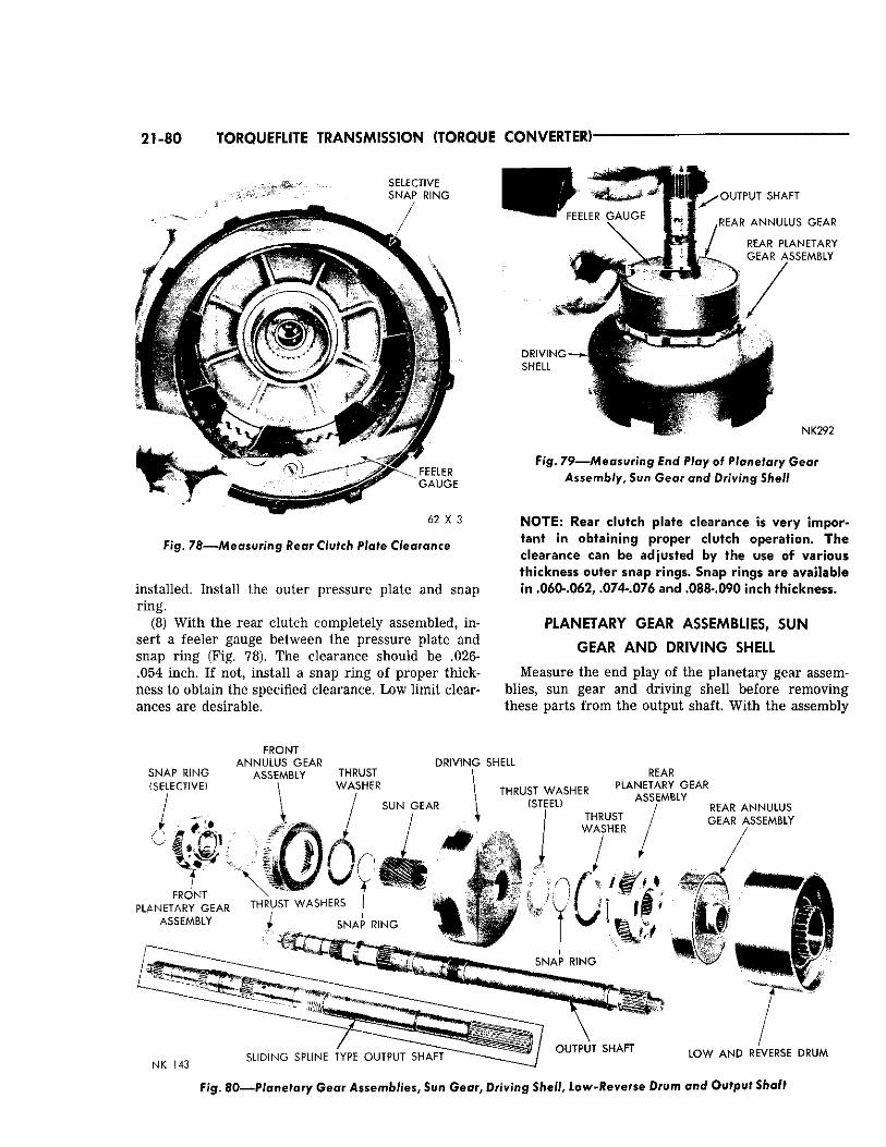
21-80 TORQUEFLITE TRANSMISSION (TORQUE CONVERTER)'
S E L E C T I V E S N A P R I N G
6 2 X 3
Fig. 78—Measuring Rear Clutch Plate Clearance
installed. Install the outer pressure plate and snap ring.
(8) With the rear clutch completely assembled, insert a feeler gauge between the pressure plate and snap ring (Fig. 78). The clearance should be .026-.054 inch. If not, install a snap ring of proper thickness to obtain the specified clearance. Low limit clearances are desirable.
Fig. 7 9 — Measur ing End Play of Planetary Gear Assembly, Sun Gear and Driving Shell
NOTE: Rear clutch plate clearance is very important in obtaining proper clutch operation. The clearance can be adjusted by the use of various thickness outer snap rings. Snap rings are available in 060-.062, .074-.076 and .088-.090 inch thickness.
PLANETARY GEAR ASSEMBLIES, SUN
GEAR AND DRIVING SHELL
Measure the end play of the planetary gear assemblies, sun gear and driving shell before removing these parts from the output shaft. With the assembly
F R O N T A N N U L U S G E A R D R I V I N G S H E L L
Fig. 80—Planetary Gear Assemblies, Sun Gear, Driving Shell, Low -Reverse Drum and Output Shaft
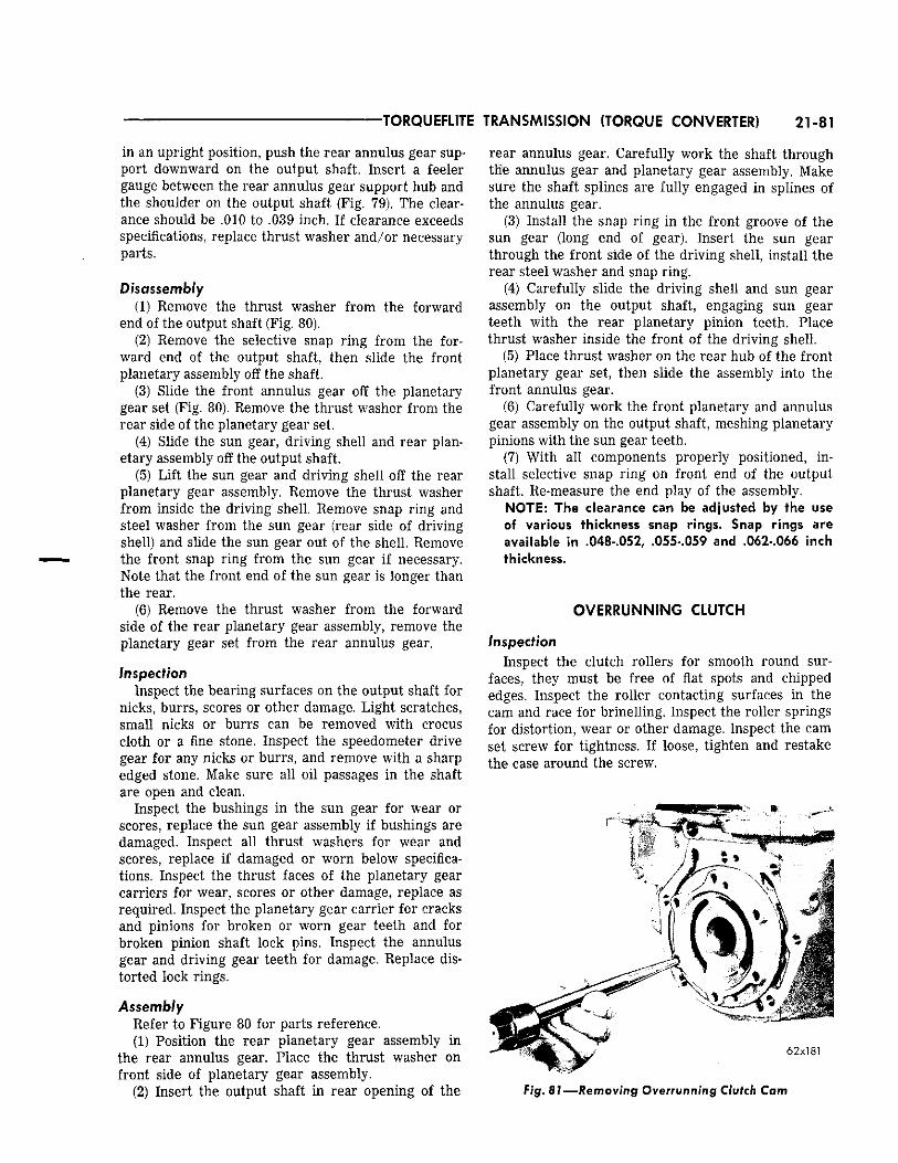
TORQUEFLITE TRANSMISSION (TORQUE CONVERTER) 21-81
in an upright position, push the rear annulus gear support downward on the output shaft. Insert a feeler gauge between the rear annulus gear support hub and the shoulder on the output shaft (Fig. 79). The clearance should be .010 to .039 inch. If clearance exceeds specifications, replace thrust washer and/or necessary parts.
Disassembly (1) Remove the thrust washer from the forward
end of the output shaft (Fig. 80). (2) Remove the selective snap ring from the for
ward end of the output shaft, then slide the front planetary assembly off the shaft.
(3) Slide the front annulus gear off the planetary gear set (Fig. 80). Remove the thrust washer from the rear side of the planetary gear set.
(4) Slide the sun gear, driving shell and rear planetary assembly off the output shaft.
(5) Lift the sun gear and driving shell off the rear planetary gear assembly. Remove the thrust washer from inside the driving shell. Remove snap ring and steel washer from the sun gear (rear side of driving shell) and slide the sun gear out of the shell. Remove the front snap ring from the sun gear if necessary. Note that the front end of the sun gear is longer than the rear.
(6) Remove the thrust washer from the forward side of the rear planetary gear assembly, remove the planetary gear set from the rear annulus gear.
Inspection Inspect the bearing surfaces on the output shaft for
nicks, burrs, scores or other damage. Light scratches, small nicks or burrs can be removed with crocus cloth or a fine stone. Inspect the speedometer drive gear for any nicks or burrs, and remove with a sharp edged stone. Make sure all oil passages in the shaft are open and clean.
Inspect the bushings in the sun gear for wear or scores, replace the sun gear assembly if bushings are damaged. Inspect all thrust washers for wear and scores, replace if damaged or worn below specifications. Inspect the thrust faces of the planetary gear carriers for wear, scores or other damage, replace as required. Inspect the planetary gear carrier for cracks and pinions for broken or worn gear teeth and for broken pinion shaft lock pins. Inspect the annulus gear and driving gear teeth for damage. Replace distorted lock rings.
Assembly Refer to Figure 80 for parts reference. (1) Position the rear planetary gear assembly in
the rear annulus gear. Place the thrust washer on front side of planetary gear assembly.
(2) Insert the output shaft in rear opening of the
rear annulus gear. Carefully work the shaft through the annulus gear and planetary gear assembly. Make sure the shaft splines are fully engaged in splines of the annulus gear.
(3) Install the snap ring in the front groove of the sun gear (long end of gear). Insert the sun gear through the front side of the driving shell, install the rear steel washer and snap ring.
(4) Carefully slide the driving shell and sun gear assembly on the output shaft, engaging sun gear teeth with the rear planetary pinion teeth. Place thrust washer inside the front of the driving shell.
(5) Place thrust washer on the rear hub of the front planetary gear set, then slide the assembly into the front annulus gear.
(6) Carefully work the front planetary and annulus gear assembly on the output shaft, meshing planetary pinions with the sun gear teeth.
(7) With all components properly positioned, install selective snap ring on front end of the output shaft. Re-measure the end play of the assembly.
NOTE: The clearance can be adjusted by the use of various thickness snap rings. Snap rings are available in .048-.052, .055-.059 and .062-.066 inch thickness.
OVERRUNNING CLUTCH
Inspection Inspect the clutch rollers for smooth round sur
faces, they must be free of flat spots and chipped edges. Inspect the roller contacting surfaces in the cam and race for brinelling. Inspect the roller springs for distortion, wear or other damage. Inspect the cam set screw for tightness. If loose, tighten and restake the case around the screw.
3
6 2 x 1 8 1
Fig. 81—Removing Overrunning Clutch Cam
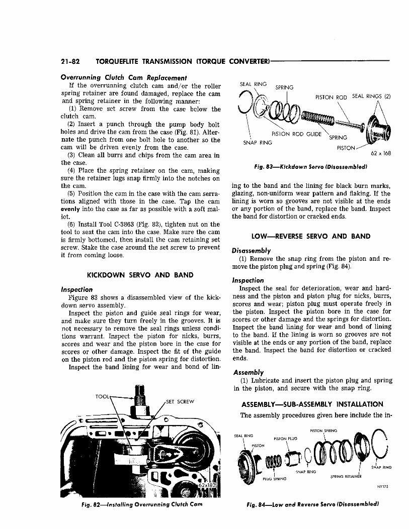
21-82 TORQUEFLITE TRANSMISSION (TORQUE CONVERTER)
Overrunning Clutch Cam Replacement If the overrunning clutch cam and/or the roller
spring retainer are found damaged, replace the cam and spring retainer in the following manner:
(1) Remove set screw from the case below the clutch cam.
(2) Insert a punch through the pump body bolt holes and drive the cam from the case (Fig. 81). Alternate the punch from one bolt hole to another so the cam will be driven evenly from the case.
(3) Clean all burrs and chips from the cam area in the case.
(4) Place the spring retainer on the cam, making sure the retainer lugs snap firmly into the notches on the cam.
(5) Position the cam in the case with the cam serrations aligned with those in the case. Tap the cam evenly into the case as far as possible with a soft mallet.
(6) Install Tool C-3863 (Fig. 82), tighten nut on the tool to seat the cam into the case. Make sure the cam is firmly bottomed, then install the cam retaining set screw. Stake the case around the set screw to prevent it from coming loose.
KICKDOWN SERVO AND BAND
Inspection Figure 83 shows a disassembled view of the kick-
down servo assembly. Inspect the piston and guide seal rings for wear,
and make sure they turn freely in the grooves. It is not necessary to remove the seal rings unless conditions warrant. Inspect the piston for nicks, burrs, scores and wear and the piston bore in the case for scores or other damage. Inspect the fit of the guide on the piston rod and the piston spring for distortion.
Inspect the band lining for wear and bond of lin-
TOOL S E T S C R E W
SEAL RING s p R ( N G
" % ^ 1 PISTON ROD SEAL RINGS (2)
SNAP RING
PISTON ROD GUIDE SPRING
P I S T O N -62 x 168
F/g . 8 3 — K i c k d o w n Servo (Disassembled)
ing to the band and the lining for black burn marks, glazing, non-uniform wear pattern and flaking. If the lining is worn so grooves are not visible at the ends or any portion of the band, replace the band. Inspect the band for distortion or cracked ends.
LOW—REVERSE SERVO AND BAND
Disassembly (1) Remove the snap ring from the piston and re
move the piston plug and spring (Fig. 84).
Inspection Inspect the seal for deterioration, wear and hard
ness and the piston and piston plug for nicks, burrs, scores and wear; piston plug must operate freely in the piston. Inspect the piston bore in the case for scores or other damage and the springs for distortion. Inspect the band lining for wear and bond of lining to the band. If the lining is worn so grooves are not visible at the ends or any portion of the band, replace the band. Inspect the band for distortion or cracked ends.
Assembly (1) Lubricate and insert the piston plug and spring
in the piston, and secure with the snap ring.
ASSEMBLY—SUB-ASSEMBLY INSTALLATION
The assembly procedures given here include the in-
PISTON SPRING SEAL RING
SPRING RETAINER
SNAP RING
NY 175
F/g . 82—Installing Overrunning Clutch Cam F / g . 84—Low and Reverse Servo (Disassembled)
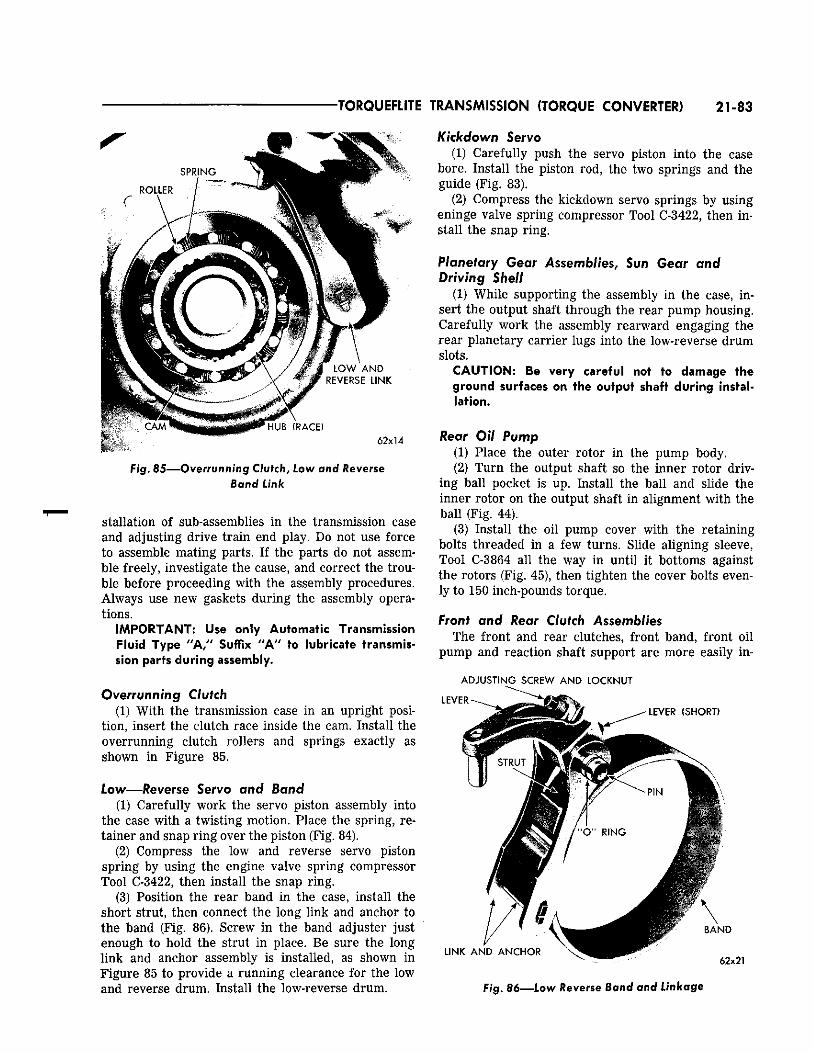
TORQUEFLITE TRANSMISSION (TORQUE CONVERTER) 21-83
C A M H U B (RACE)
6 2 x 1 4
Fig. 85—Overrunning Clutch, Low and Reverse Band Link
stallation of sub-assemblies in the transmission case and adjusting drive train end play. Do not use force to assemble mating parts. If the parts do not assemble freely, investigate the cause, and correct the trouble before proceeding with the assembly procedures. Always use new gaskets during the assembly operations.
IMPORTANT: Use only Automatic Transmission Fluid Type "A," Suffix "A" to lubricate transmission parts during assembly.
Overrunning Clutch (1) With the transmission case in an upright posi
tion, insert the clutch race inside the cam. Install the overrunning clutch rollers and springs exactly as shown in Figure 85.
Low—Reverse Servo and Band (1) Carefully work the servo piston assembly into
the case with a twisting motion. Place the spring, retainer and snap ring over the piston (Fig. 84).
(2) Compress the low and reverse servo piston spring by using the engine valve spring compressor Tool C-3422, then install the snap ring.
(3) Position the rear band in the case, install the short strut, then connect the long link and anchor to the band (Fig. 86). Screw in the band adjuster just enough to hold the strut in place. Be sure the long link and anchor assembly is installed, as shown in Figure 85 to provide a running clearance for the low and reverse drum. Install the low-reverse drum.
Kickdown Servo (1) Carefully push the servo piston into the case
bore. Install the piston rod, the two springs and the guide (Fig. 83).
(2) Compress the kickdown servo springs by using eninge valve spring compressor Tool C-3422, then install the snap ring.
Planetary Gear Assemblies, Sun Gear and Driving Shell
(1) While supporting the assembly in the case, insert the output shaft through the rear pump housing. Carefully work the assembly rearward engaging the rear planetary carrier lugs into the low-reverse drum slots.
CAUTION: Be very careful not to damage the ground surfaces on the output shaft during installation.
Rear Oil Pump (1) Place the outer rotor in the pump body. (2) Turn the output shaft so the inner rotor driv
ing ball pocket is up. Install the ball and slide the inner rotor on the output shaft in alignment with the ball (Fig. 44).
(3) Install the oil pump cover with the retaining bolts threaded in a few turns. Slide aligning sleeve, Tool C-3864 all the way in until it bottoms against the rotors (Fig. 45), then tighten the cover bolts evenly to 150 inch-pounds torque.
Front and Rear Clutch Assemblies The front and rear clutches, front band, front oil
pump and reaction shaft support are more easily in-
A D J U S T I N G SCREW A N D LOCKNUT
62x21
Fig. 86—Low Reverse Band and Linkage
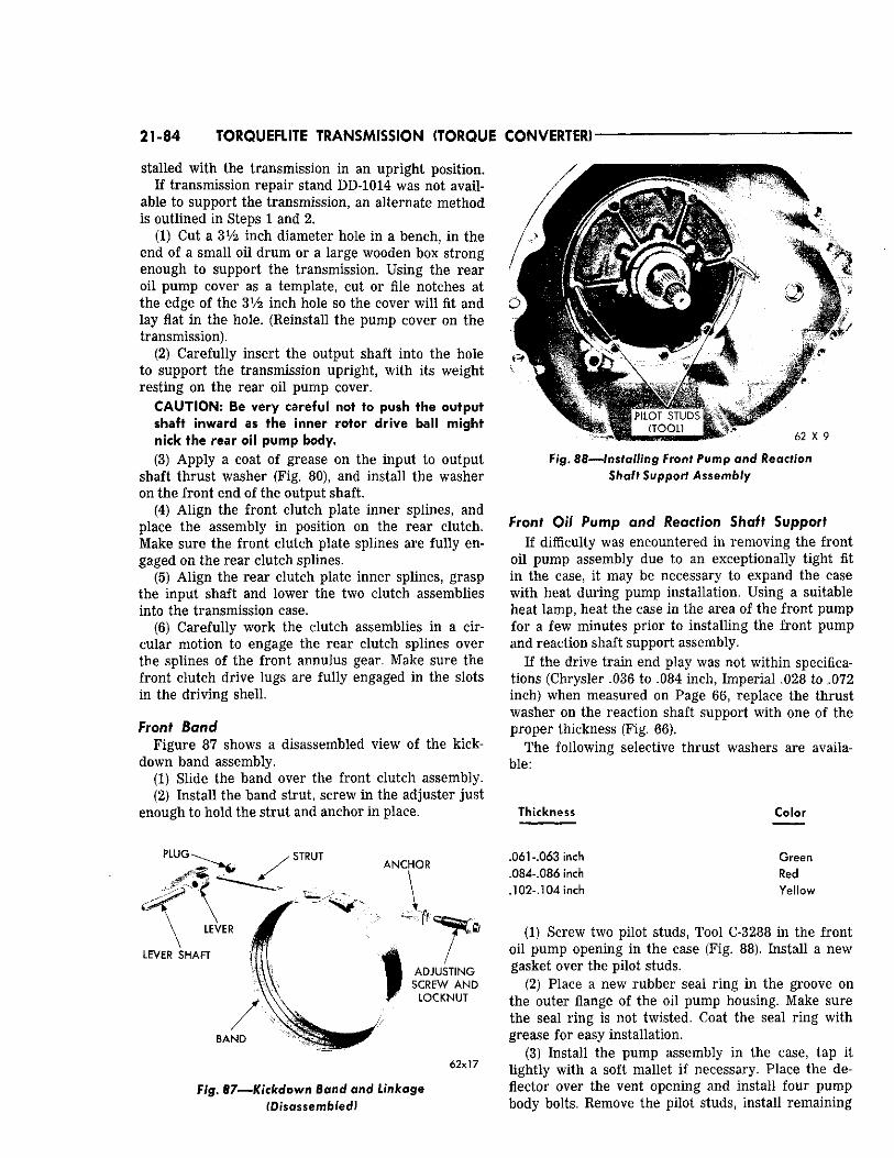
21-84 TORQUEFLITE TRANSMISSION (TORQUE CONVERTER)
stalled with the transmission in an upright position. If transmission repair stand DD-1014 was not avail
able to support the transmission, an alternate method is outlined in Steps 1 and 2.
(1) Cut a 3X/2 inch diameter hole in a bench, in the end of a small oil drum or a large wooden box strong enough to support the transmission. Using the rear oil pump cover as a template, cut or file notches at the edge of the 3V2 inch hole so the cover will fit and lay flat in the hole. (Reinstall the pump cover on the transmission).
(2) Carefully insert the output shaft into the hole to support the transmission upright, with its weight resting on the rear oil pump cover.
CAUTION: Be very careful not to push the output shaft inward as the inner rotor drive ball might nick the rear oil pump body. (3) Apply a coat of grease on the input to output
shaft thrust washer (Fig. 80), and install the washer on the front end of the output shaft.
(4) Align the front clutch plate inner splines, and place the assembly in position on the rear clutch. Make sure the front clutch plate splines are fully engaged on the rear clutch splines.
(5) Align the rear clutch plate inner splines, grasp the input shaft and lower the two clutch assemblies into the transmission case.
(6) Carefully work the clutch assemblies in a circular motion to engage the rear clutch splines over the splines of the front annulus gear. Make sure the front clutch drive lugs are fully engaged in the slots in the driving shell.
Front Band Figure 87 shows a disassembled view of the kick-
down band assembly. (1) Slide the band over the front clutch assembly. (2) Install the band strut, screw in the adjuster just
enough to hold the strut and anchor in place.
F/g. 88—Installing Front Pump and Reaction Shaft Support Assembly
Front Oil Pump and Reaction Shaft Support If difficulty was encountered in removing the front
oil pump assembly due to an exceptionally tight fit in the case, it may be necessary to expand the case with heat during pump installation. Using a suitable heat lamp, heat the case in the area of the front pump for a few minutes prior to installing the front pump and reaction shaft support assembly.
If the drive train end play was not within specifications (Chrysler .036 to .084 inch, Imperial .028 to .072 inch) when measured on Page 66, replace the thrust washer on the reaction shaft support with one of the proper thickness (Fig. 66).
The following selective thrust washers are available:
Thickness Color
PLUG STRUT ANCHOR
\ ^ LEVER
LEVER SHAFT
\\\
BAND
ADJUSTING SCREW A N D
LOCKNUT
62x17
Fig. 87—Kickdown Band and Linkage (Disassembled)
.061-.063 inch
.084-.086 inch
.102-.104 inch
Green Red Yellow
(1) Screw two pilot studs, Tool C-3288 in the front oil pump opening in the case (Fig. 88). Install a new gasket over the pilot studs.
(2) Place a new rubber seal ring in the groove on the outer flange of the oil pump housing. Make sure the seal ring is not twisted. Coat the seal ring with grease for easy installation.
(3) Install the pump assembly in the case, tap it lightly with a soft mallet if necessary. Place the deflector over the vent opening and install four pump body bolts. Remove the pilot studs, install remaining
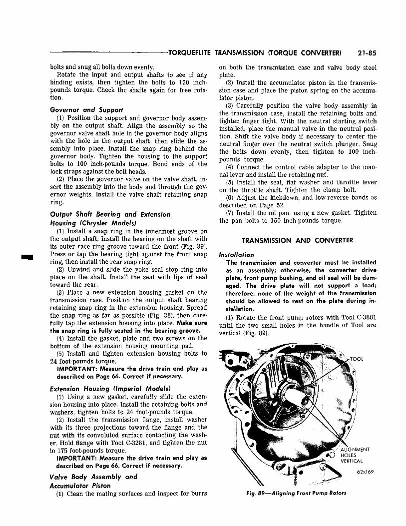
•TORQUEFLITE TRANSMISSION (TORQUE CONVERTER) 21-85
bolts and snug all bolts down evenly. Rotate the input and output shafts to see if any
binding exists, then tighten the bolts to 150 inch-pounds torque. Check the shafts again for free rotation.
Governor and Support (1) Position the support and governor body assem
bly on the output shaft. Align the assembly so the governor valve shaft hole in the governor body aligns with the hole in the output shaft, then slide the assembly into place. Install the snap ring behind the governor body. Tighten the housing to the support bolts to 100 inch-pounds torque. Bend ends of the lock straps against the bolt heads.
(2) Place the governor valve on the valve shaft, insert the assembly into the body and through the governor weights. Install the valve shaft retaining snap ring.
Output Shaft Bearing and Extension Housing (Chrysler Models)
(1) Install a snap ring in the innermost groove on the output shaft. Install the bearing on the shaft with its outer race ring groove toward the front (Fig. 39). Press or tap the bearing tight against the front snap ring, then install the rear snap ring.
(2) Unwind and slide the yoke seal stop ring into place on the shaft. Install the seal with lips of seal toward the rear.
(3) Place a new extension housing gasket on the transmission case. Position the output shaft bearing retaining snap ring in the extension housing. Spread the snap ring as far as possible (Fig. 38), then carefully tap the extension housing into place. Make sure the snap ring is fully seated in the bearing groove.
(4) Install the gasket, plate and two screws on the bottom of the extension housing mounting pad.
(5) Install and tighten extension housing bolts to 24 foot-pounds torque.
IMPORTANT: Measure the drive train end play as described on Page 6 6 . Correct if necessary.
Extension Housing (Imperial Models) (1) Using a new gasket, carefully slide the exten
sion housing into place. Install the retaining bolts and washers, tighten bolts to 24 foot-pounds torque.
(2) Install the transmission flange, install washer with its three projections toward the flange and the nut with its convoluted surface contacting the washer. Hold flange with Tool C-3281, and tighten the nut to 175 foot-pounds torque.
IMPORTANT: Measure the drive train end play as described on Page 6 6 . Correct if necessary.
Valve Body Assembly and Accumulator Piston
(1) Clean the mating surfaces and inspect for burrs
on both the transmission case and valve body steel plate.
(2) Install the accumulator piston in the transmission case and place the piston spring on the accumulator piston.
(3) Carefully position the valve body assembly in the transmission case, install the retaining bolts and tighten finger tight. With the neutral starting switch installed, place the manual valve in the neutral position. Shift the valve body if necessary to center the neutral finger over the neutral switch plunger. Snug the bolts down evenly, then tighten to 100 inch-pounds torque.
(4) Connect the control cable adapter to the manual lever and install the retaining nut.
(5) Install the seal, flat washer and throttle lever on the throttle shaft. Tighten the clamp bolt.
(6) Adjust the kickdown, and low-reverse bands as described on Page 52.
(7) Install the oil pan, using a new gasket. Tighten the pan bolts to 150 inch-pounds torque.
TRANSMISSION AND CONVERTER
Installation The transmission and converter must be installed as an assembly; otherwise, the converter drive plate, front pump bushing, and oil seal will be damaged. The drive plate will not support a load; therefore, none of the weight of the transmission should be allowed to rest on the plate during installation. (1) Rotate the front pump rotors with Tool C-3881
until the two small holes in the handle of Tool are vertical (Fig. 89).
F i g . 89—Aligning Front Pump Rotors
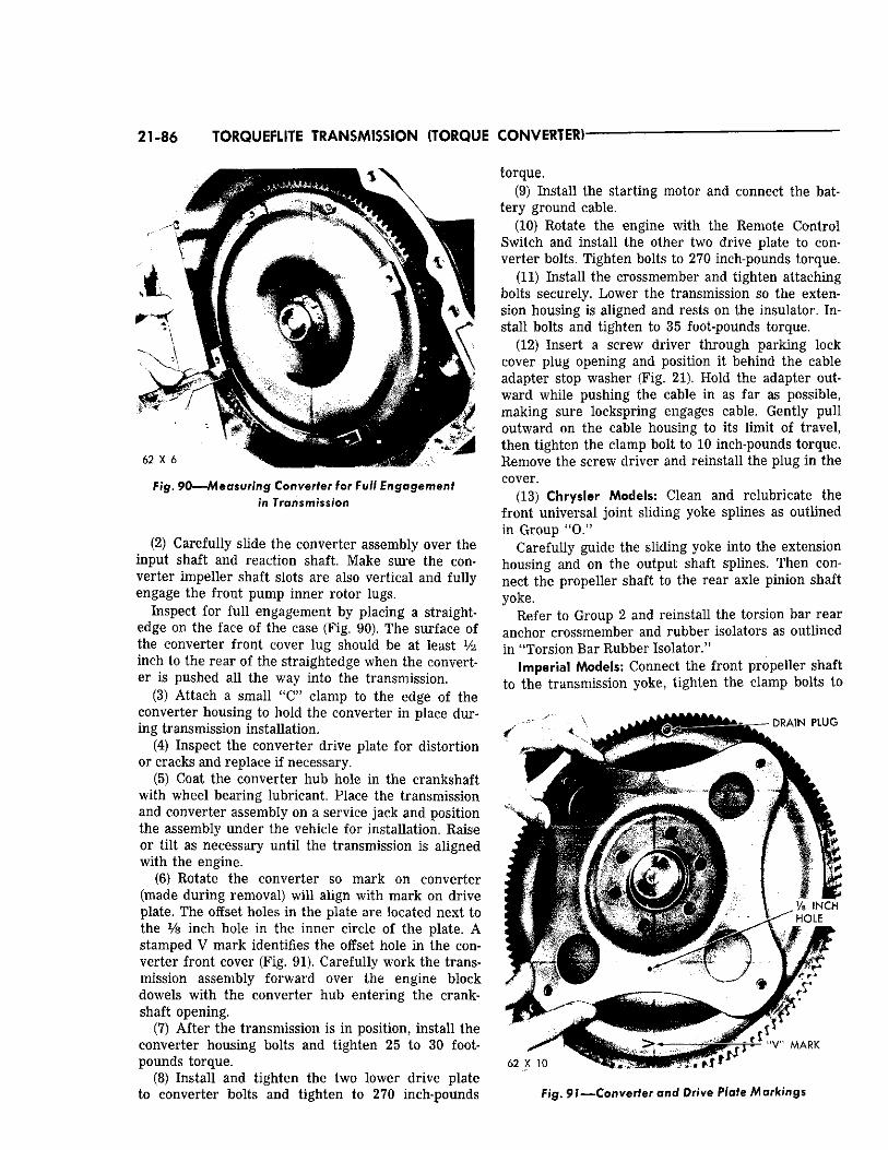
21-86 TOiGUEFLITE TRANSMISSION (TORQUE CONVERTER)'
F/g. 90—Measuring Converter for Full Engagement in Transmission
(2) Carefully slide the converter assembly over the input shaft and reaction shaft. Make sure the converter impeller shaft slots are also vertical and fully engage the front pump inner rotor lugs.
Inspect for full engagement by placing a straightedge on the face of the case (Fig. 90). The surface of the converter front cover lug should be at least Vi inch to the rear of the straightedge when the converter is pushed all the way into the transmission.
(3) Attach a small "C" clamp to the edge of the converter housing to hold the converter in place during transmission installation.
(4) Inspect the converter drive plate for distortion or cracks and replace if necessary.
(5) Coat the converter hub hole in the crankshaft with wheel bearing lubricant. Place the transmission and converter assembly on a service jack and position the assembly under the vehicle for installation. Raise or tilt as necessary until the transmission is aligned with the engine.
(6) Rotate the converter so mark on converter (made during removal) will align with mark on drive plate. The offset holes in the plate are located next to the Vs inch hole in the inner circle of the plate. A stamped V mark identifies the offset hole in the converter front cover (Fig. 91). Carefully work the transmission assembly forward over the engine block dowels with the converter hub entering the crankshaft opening.
(7) After the transmission is in position, install the converter housing bolts and tighten 25 to 30 footpounds torque.
(8) Install and tighten the two lower drive plate to converter bolts and tighten to 270 inch-pounds
torque. (9) Install the starting motor and connect the bat
tery ground cable. (10) Rotate the engine with the Remote Control
Switch and install the other two drive plate to converter bolts. Tighten bolts to 270 inch-pounds torque.
(11) Install the crossmember and tighten attaching bolts securely. Lower the transmission so the extension housing is aligned and rests on the insulator. Install bolts and tighten to 35 foot-pounds torque.
(12) Insert a screw driver through parking lock cover plug opening and position it behind the cable adapter stop washer (Fig. 21). Hold the adapter outward while pushing the cable in as far as possible, making sure lockspring engages cable. Gently pull outward on the cable housing to its limit of travel, then tighten the clamp bolt to 10 inch-pounds torque. Remove the screw driver and reinstall the plug in the cover.
(13) Chrysler Models: Clean and relubricate the front universal joint sliding yoke splines as outlined in Group "O."
Carefully guide the sliding yoke into the extension housing and on the output shaft splines. Then connect the propeller shaft to the rear axle pinion shaft yoke.
Refer to Group 2 and reinstall the torsion bar rear anchor crossmember and rubber isolators as outlined in "Torsion Bar Rubber Isolator."
Imperial Models: Connect the front propeller shaft to the transmission yoke, tighten the clamp bolts to
F/g. 97— 'Converter and Drive Plate Markings
TORQUEFLITE TRANSMISSION (TORQUE CONVERTER) 21-87
170 inch-pounds torque. Place the center bearing housing shims under the housing, install the retaining bolts and tighten to 35 foot-pounds torque.
(14) Install the speedometer drive pinion and sleeve.
(15) Connect the oil cooler lines to the transmission. Install the oil filler tube.
(16) Connect the throttle rod to the relay lever at the left side of the transmission.
(17) Place the selector lever in the park position. Insert the control cable in the transmission case,
push inward on the cable making sure the lock spring engages the cable. Install the control cable adjusting wheel lock screw.
(18) Connect the wire to the neutral starting switch. (19) Install the cover plate in front of the convert
er assembly. (20) Refill the transmission with Automatic Trans
mission Fluid, Type "A" Suffix "A." N O T E : To comple te ly adjust the t h r o t t l e l inkage, gearshif t con t ro l cable, and neu t ra l s ta r t ing swi tch , refer to Pages 50, 51 and 52.