Embed Size (px)
Citation preview

Transmission Planning Standards for theBaltimore Gas & Electric Company
Transmission System
Prepared By:Transmission Planning Unit
Baltimore Gas & Electric Company


2
Table of Contents
1. INTRODUCTION 4
2. PLANNING OBJECTIVES AND METHODS 5
2.1. Planning Objectives 5
2.2. Planning Methods 5
3. GLOSSARY 6
4. RELIABILITY CRITERIA & TESTING METHODOLOGY 8
4.1. Transmission System Model Creation 84.1.1. Introduction 84.1.2. Overhead Transmission Lines 84.1.3. Underground Transmission Lines 84.1.4. Interconnection to Transmission Owners 84.1.5. Interconnection Customers 94.1.6. Transformers 94.1.7. Loads 94.1.8. Capacitors 94.1.9. Reactors 104.1.10. Circuit Breakers 104.1.11. Transmission Model Completion 10
4.2. Steady State Analysis 104.2.1. Introduction 104.2.2. Creating Contingency Files 104.2.3. Thermal Analysis 124.2.4. Voltage & Reactive Analysis 144.2.5. Voltage Control Philosophy 15
4.3. Short Circuit Analysis 174.3.1. Introduction 174.3.2. Circuit Breaker Database 174.3.3. Performing the Analysis 184.3.4. Possible Solutions 24
4.4. Dynamic Analysis 244.4.1. Introduction 244.4.2. Disturbances 264.4.3. Performing the Analysis 264.4.4. Possible Solutions 27
4.5. Emergency Import Capability 27
5. PLANNING DESIGN GUIDELINES FOR SYSTEM EXPANSION 30

3
5.1. Substation Expansion Philosophy 30
5.2. Extra High Voltage (EHV) Reliability Criteria and Practice 30
5.3. High Voltage (230 kV) Reliability Criteria and Practice 325.3.1. 500/230 kV Substations and 230 kV Switching Stations 325.3.2. 230/115 kV Substations 345.3.3. 230/34.5 kV and 230/13.8 kV Substations 35
5.4. High Voltage (115 kV) Reliability Criteria and Practice 365.4.1. 115 kV switching Substations 365.4.2. Downtown Baltimore 115 kV Substations 375.4.3. Requirements for Substation Separation 40
5.5. Additional Requirements for Interconnection Facilities 41
5.6. Additional Requirements for 500 kV interconnection Facilities 43
5.7. Restrictions of Sole Use or Dedicated Facilities 45
5.8. Substation Expansion from Ring Bus to Breaker and Half Design 45
6. RADIAL CRITERIA 46
6.1. Introduction 46
6.2. Expansion 46
6.3. Other BGE Radial Transmission System Criteria 46
7. REMEDIAL ACTION SCHEME (RAS) CRITERIA 47
7.1. Introduction 47
7.2. Allowable Uses for RAS 47
7.3. Temporary RAS Installation 477.3.1. Restrictions on the Use of Temporary RAS Installations 47
7.4. Permanent RAS Installation 487.4.1. Restrictions on Permanent RAS Use 48
7.5. RAS Design & Planning 497.5.1. Design 49
7.6. Planning 49

4
Introduction1.The Baltimore Gas and Electric Company (BGE), a regulated energy delivery company in CentralMaryland, is a subsidiary of the Exelon Corporation (EXC).
BGE is an electric and gas public transmission and distribution utility company with a 2,300-square-mileservice territory that covers the City of Baltimore and all or part of ten counties in Central Maryland.
BGE’s transmission facilities are connected to those of neighboring utility systems as part of the PJMInterconnection. BGE is a member of the Regional Transmission Organization (RTO), PJM, in theDelaware, Illinois, Indiana, Kentucky, Maryland, Michigan, New Jersey, North Carolina, Ohio,Pennsylvania, Virginia, West Virginia and the District of Columbia areas. Membership providesopportunities for bulk power sales and allows the use of larger, more efficient generating units, resultingin lower costs to customers and increased service reliability.
Under the PJM Tariff and various agreements, BGE and other market participants can use regionaltransmission facilities for energy, capacity and ancillary services.
BGE is committed to providing safe and reliable service to our customers through the operation,maintenance, modification and expansion of the electric system to meet the existing and future needs ofour customers.
This will be done by responsibly planning and constructing interconnection facilities, transmissionsystems, distribution systems, substations, and land for future substations and right-of-ways.
The BGE planning standards and principles discussed in this document are intended to provide for thedevelopment of an economical and reliable transmission system. At the very minimum, BGE’stransmission planning standards for the bulk electric system are consistent with ReliabilityFirst RegionalReliability Council Standards and the North American Electric Reliability Corporation (NERC) PlanningStandards. As the regional RTO, PJM is responsible for planning the bulk transmission system, includingBGE’s facilities, under the PJM Open Access Transmission Tariff and Schedule 6 of the PJM OperatingAgreement.
The application of prudent engineering and business judgment must concurrently be exercised alongwith the employment of these standards. Circumstances may dictate that these standards andphilosophies as discussed herein require modification in the future. Therefore, the employment of thesestandards should not be used to preclude the consideration of other sound designs or proposals.

5
Planning Objectives and Methods2.Planning Objectives2.1.
The BGE system has been planned and constructed over the last 100 years. During that timethe needs and methods have been in a state of continuous evolution. Because it is not feasibleto continuously redesign the entire system, much of the existing infrastructure was built in amanner that are not ideal for today’s needs. The objective of this standard is to define themethods and practices that BGE feels are appropriate to provide the characteristics that aredesirable in today’s environment. These are some of the characteristics considered whenplanning the expansion of the BGE Transmission system:
Reliability Security Public Safety Personnel Safety Operability Environmental Impact Economics Flexibility and future expandability Adequacy
Planning Methods2.2.
The BGE Transmission System consists of assets at three voltage levels. The 500kV systemfunctions to import power from other parts of the PJM system. This power is fed to the BGE230kV system at our 500/230kV stations. The 230kV system transmits power to a number of230/115kV stations around the BGE system. In addition to the power taken from the 500kVsystem, the 230kV system serves to connect local generation. There are also a few 230kV linesthat interconnect with neighboring utilities.
Power is supplied to the 115kV system at our 230/115kV substation as well as from a numberof local generating stations. The 115kV system connects to the 230kV system at a number ofplaces. In some cases, substations are supplied directly from a network connected 115kVstation; but in many instances, two 115kV radial circuit taps extend from the network system tosupply one or more distribution substations.
In general, load on the BGE system is served from the 115kV system. In some instances, BGEconnects load directly to the 230kV system. This is general only done if 115kV circuits are notavailable or when security or expected loads dictate the necessity to do so. BGE does not allowload to be connected directly to the 500kV system.

6
Glossary3.ASPEN (Advanced Systems for Power Engineering, Inc.) – The software company that makesASPEN Oneliner and the ASPEN Breaker Rating Module used by BGE for circuit breaker short circuitanalysis.
Bulk Electric System – BGE equipment and facilities 100kV and above that meet the ReliabilityFirstdefinition of the Bulk Electric System. These facilities are provided by the official BGE BES facilities list.
BGE Transmission System – The system of Extra High Voltage (EHV) and High Voltage (HV) facilitieswithin the BGE Transmission Zone of the PJM Transmission System, including equipment and facilities100kV and above. These facilities include BES facilities as well as radial circuits and substations that donot meet the ReliabilityFirst BES facility definition.
Bus – When referring to the term “bus” in these standards, all devices that would be initially interrupted,or the devices within a zone of protection including a bus should be considered part of the bus. Busoutages are significant when evaluating the transmission system for voltage drop or emergency thermalrating violations.
Bus Section – “Bus section” refers to any section of a bus or section of another element that can beisolated via any switching device and operated by a bus. Bus section outages are significant whenevaluating the transmission system for voltage magnitude or normal thermal rating violations.
Cascading System Disturbance – A system disturbance where the interruption of a facility within asingle zone of protection causes a second adjacent zone of protection to operate interrupting subsequentfacilities and then causing a third adjacent zone of protection to operate. This in turn could possibly causeother system equipment to be interrupted leading to a system collapse or blackout.
Dedicated Facility - A facility that is constructed for the use of a single customer.
Element - Any electrical device with terminals that may be connected to other electrical devices such as agenerator, transformer, circuit breaker, bus section, or transmission line. An element may be comprised ofone or more components.
Extra High Voltage (EHV) – Those transmission facilities operating at a voltage of 345 kV orhigher.
High Voltage (HV) – Those transmission facilities operating at a voltage of 115 kV or higher but less than345 kV.
LAS (Load Analysis Subcommittee) – PJM Planning Subcommittee that is responsible for the long-termforecast of PJM peaks, energy and load management by zone.
Interconnection Customers/Developer
MMWG (Multiregional Modeling Working Group) – The NERC working group that develops thetransmission loadflow models used throughout the industry for planning and reliability analysis.
– A company or group seeking to interconnect with the BGE Transmission System. The interconnection customer/developer may be seeking to connect Generation, Transmission, or End-User (load serving) facilities

7
NERC (North American Electric Reliability Council) – The regulatory entity whose mission is to ensurethe reliability of the Bulk-Power System in North America. NERC develops and enforces reliabilitystandards and is subject to oversight by the Federal Energy Regulatory Commission.
Network Transmission Facility – A transmission facility whose main purpose is to transmit power overdistances rather than supply power directly to load.
Over-duty Circuit Breaker – A circuit breaker with available fault current in excess of its interruptingcapability.
Radial Transmission Facility – A non-networked circuit on which power tends to flow in one direction toserve load. Radial transmission facilities on the BGE System are operated at 230 kV and 115 kV.
RF (ReliabilityFirst) – The NERC regional reliability council that BGE is a member of or any successororganization.
PSS/E (Power System Simulator for Engineering) – The software product produced by Siemen’sPower Technologies, Inc. (PTI) used by BGE for loadflow, short circuit, and stability analysis.
RTEP – (Regional Transmission Expansion Plan) – The transmission system plan that is developed byPJM, which encompasses the entire PJM footprint and covers a five-year future timeframe.
RTEPP – (Regional Transmission Expansion Planning Process) – The process through which PJMdevelops the RTEP.
RAS – (Remedial Action Scheme) – A scheme designed to detect predetermined System conditions andautomatically take corrective actions that may include, but are not limited to, curtailing or trippinggeneration or other sources, curtailing or tripping load, or reconfiguring a System(s).
Zone of Protection - A section of the transmission system, separated or bounded by breakers, which isautomatically isolated from the balance of the system when a fault occurs within its boundary.
Symbols:

8
Reliability Criteria & Testing Methodology4.Transmission System Model Creation4.1.
4.1.1. Introduction
In order to perform thermal steady state analysis, voltage and reactive power analysis, shortcircuit analysis, dynamic analysis, and emergency import capability analysis with any degree ofconfidence, all of the major elements of the electrical system must be included in the modelalong with their appropriate electrical characteristics and power capabilities. These include butare not limited to transmission lines, transformers, capacitors, reactors, circuit breakers,generators, and loads. The model is developed on a per unit basis on a 100 MVA base.
4.1.2. Overhead Transmission Lines
Transmission lines within BGE’s service territory should be modeled with all appropriateelectrical parameters and capabilities. For overhead lines, the electrical parameters arecalculated using the physical parameters of each transmission circuit.
All of the appropriate physical characteristics of the conductor and the structures supportingthose conductors are entered into an impedance calculation program which then provides thetotal positive sequence impedance, zero sequence impedance, charging, and mutual couplinginductance of each line. This data is then used in the load flow, stability, and short circuitmodels.
For proposed lines, the values are calculated using typical values for similar transmission lines.Once the lines are constructed, the actual electrical parameters are calculated from the as-builtphysical characteristics. For existing lines that have been modified, the new electricalparameters are to be calculated if the physical change is determined by BGE to be electricallysignificant.
The thermal ratings of overhead lines are calculated using the PJM Transmission andSubstation Design Subcommittee’s Bare Overhead Conductor Rating report as a guide. Normaland emergency thermal ratings are input into the transmission system models. All ratingschanges are reflected in the electrical models, regardless of the degree of change.
4.1.3. Underground Transmission Lines
All of the appropriate physical characteristics of both new and existing underground cables areentered into an impedance calculation program which then provides the total positive sequenceimpedance, zero sequence impedance, and charging. This data is then used in the load flow,stability, and short circuit models. For new underground circuits, following a cable (fluid filled orsolid dielectric) fault, reclosing should not be used to test the circuit.
Underground lines associated with overhead should have cable fault detection whenterminated. The fault detection will prevent reclose into the faulted cable.
4.1.4. Interconnection to Transmission Owners
As part of the PJM RTO, BGE has interconnections to other transmission owners at the 500 kV,230 kV, and the 115 kV levels.
The impedance calculations for these lines are the joint responsibility of PJM and thetransmission owners. Each transmission owner verifies the impedance value of the line up tothe service territory boundary.

9
It is also the responsibility of the transmission owner to produce and maintain the electricalratings of the interconnection lines up to the point of interconnection, including any substationlimitations. The lowest ratings of each circuit are used by PJM in the planning models.
4.1.5. Interconnection Customers
The data associated with all interconnection customers, including generation and merchanttransmission, are provided to PJM by the interconnection customer. This data is entered intosystem models by PJM.
Any changes to existing generators that impact the short-circuit, load flow or stability modelsare provided by the interconnection customer to PJM. PJM then includes these values in themodels. Changes to existing interconnection customer facilities are also provided by theinterconnection customer to PJM.
For new interconnection customers, the data and modeling of all the interconnection facilitiesare provided by PJM, using data from the interconnection customer and the transmissionowner. The transmission owner provides the parameters for any facilities that the transmissionowner constructs for an interconnection customer.
4.1.6.Transformers
The Bulk power transformers are rated in accordance with the BES methodology maintained bythe BGE Substation Engineering organization.
4.1.7. Loads
All of the loads are input at each load-serving transformer low side bus that is represented inthe electric system model. Several load levels are modeled as required by the MMWGSchedule for each study year. The typical loads represented are:
Summer Peak Load – defined as summer peak demand expected to be served, reflectingload reductions for peak shaving.
Winter Peak Load - defined as winter peak demand expected to be served, reflectingload reductions for peak shaving.
Light Load – defined as a typical early morning load level in April, modeling at or nearminimum load conditions.
Spring Peak Load – defined as typical April peak load conditions.
Fall Peak Load – defined as typical October peak load conditions.
The most current area load forecast is applied at each transformer bus in the load flow model.The total system load in BGE’s service territory is then scaled to match the forecasted seasonalload for BGE’s Service Territory as provided by PJM’s Load Analysis Subcommittee (LAS). Thissame methodology is applied to load data modeling within models that are provided to theMMWG as well as the PJM RTEP and other NERC Planning models provided by BGE.
4.1.8. Capacitors
In the models, distribution capacitors are represented as separate and distinct pieces ofequipment and not netted with the reactive load.
For each transmission supplied substation, capacitors are modeled on the low-side of thesubstation assuming unity power factor on the high side, approximating the sum of all of the13kV line capacitors, distribution supplied substation capacitors, and 34.5kV line capacitors,and transmission supplied substation capacitors expected to be available for the time frame

10
being studied.The capacitors are modeled with continuous operation, showing the smallincrements of capacitance that can be brought on during actual system operation.
Bulk Power capacitors are modeled to reflect the blocks of capacitance that are switched onwith the capacitor’s operation. Values are input into the models that best represent the controlscheme of the capacitors on the distribution system.
Actual operating voltage schedules are set by distribution planners and followed as best aspossible when modeling the transmission system. Section 4.2.5 better clarifies system voltagescheduling.
4.1.9. Reactors
Most reactors in BGE’s system are located on distribution feeders and therefore are notrepresented in the transmission models. For those reactors located on the transmission systemor on the low-side buses supplying distribution feeders, impedance values are calculated andincluded in the transmission system model.
4.1.10. Circuit Breakers
BGE maintains a circuit breaker database for all breakers on the system. Data for short circuitinterrupting capabilities, contact parting times, and nameplate interrupting times are obtainedfrom this database and these values are entered into the ASPEN transmission system shortcircuit model. All of these parameters are based on ANSI Standard C37.010-1979. In additionto each breaker’s physical characteristics, the ASPEN short circuit models additionally includesystem configuration information.
4.1.11. Transmission Model Completion
All of the components discussed in sections 4.1.2 to 4.1.10 are joined together to create BGE’sTransmission System model. The model represents all available facilities and creates thenormal system configuration of the transmission system. BGE supplies modeling data to PJM tocombine with information from all of the transmission owners, generation providers, and loadserving entities, as well as transfers between adjacent control areas to develop the PJM RTEPmodels. The PJM RTEP models are used to perform analysis and assist in the development offuture expansion plans by PJM members.
PJM provides the same data to ReliabilityFirst to combine with information from all of thetransmission owners, generation providers, and load serving entities, as well as transfersbetween adjacent control areas within the ReliabilityFirst footprint to develop MMWG modelsused to perform reliability assessments.
The PJM RTEP and MMWGRF models are then used by BGE along with load data from ourinternal distribution areas to develop power flow models for internal analysis. The system isevaluated based on normal system configuration and abnormal or emergency systemconfigurations as set forth within this document.
Steady State Analysis4.2.
4.2.1. Introduction
To ensure that BGE’s transmission system is planned and operated safely, economically, andreliably, steady state analysis must be performed. This analysis is performed to ensure that thesystem meets all NERC, RF, PJM and BGE standards under normal operations and given avariety of outages or contingencies and other operating conditions, where applicable.
4.2.2. Creating Contingency Files

11
The BGE Bulk Electric System is tested based on the NERC, PJM, RF, and BGE standards.These standards define the tests for system operation with no contingencies, single elementcontingencies and multiple element contingencies. The contingency definitions used by BGEare the same as applicable NERC TPL contingency definitions. The remaining BGE highvoltage transmission system is tested based on these contingencies and the BGE criteria laidout within this document.
These tests are used to evaluate how the system responds to each of the contingencies, whichdetermines whether or not there are reliability criteria violations.
Actual operation of the system, including relay operation, automatic changeovers, and outagesequencing are modeled as accurately as possible using input from transmission operationsand system protection engineers. These two organizations are the most familiar with the actualoperation and maintenance practices that determine the system configuration during normaland abnormal operation.
Normal, abnormal, and emergency configurations are evaluated against the NERC, RF, PJM orBGE reliability requirements as appropriate.
Line Outages4.2.2.1.
Many of the contingencies that are evaluated are outages of transmission circuits. For thepurpose of analysis, transmission circuits, in general, are defined as the path or facilitiesbetween circuit breakers that are within one zone of protection. In practice, transmissioncircuits can supply more than one distribution substation between breakers resulting in theloss of more than one transformer for a single line outage. In this case, it must bedetermined whether the stations supplied are equipped with high-side or low-sideautomatic changeover schemes that are designed to transfer load to other transmission-supplied substations following such contingencies. For these scenarios, distributionplanners are consulted to verify the modeling of distribution transfers resulting from thetransmission outages. The worst-case outages must be determined and accuratelysimulated.
Transformer Outages4.2.2.2.
Transformer Outages follow the same rules as circuit or line outages as discussed above;i.e. each contingency should be simulated by interrupting facilities within one zone ofprotection. The simulation must also recognize that some transformer outages result in theloss of circuits or other transformers. Each outage and the particular cause of the outagewill determine how the system is reconfigured. As with line outages, it must be determinedwhere load transfers occur and how the other transformers are impacted.
Shunt Device Outages4.2.2.3.
Shunt device outages follow the same rules as circuit or line outages as discussed above;i.e. each contingency should be simulated by interrupting facilities within one zone ofprotection.
Bus Outages4.2.2.4.
Some bus outages will result in the loss of transformers or transmission circuits. As such,the guidelines for transformer and line outages should be followed when simulating busoutages. Bus outages on the BGE system will interrupt all facilities within the zone ofprotection that are solely dependent on the bus for system connectivity.
12
As with the previous contingencies, the impacts to the rest of the transmission anddistribution system must be reviewed to see how the system automatically responds.
Generator Outages4.2.2.5.
Most generators are supplied through a synchronizing breaker, and thus, the loss of agenerator is isolated from the rest of the system. Each switching station that generation isconnected into should be reviewed carefully to verify that the disturbance is isolated, i.e.no other equipment is lost.
To more realistically simulate the network response to the sudden loss of one or moregenerators, an inertial power flow solution is normally utilized when determining the steadystate effects of generator contingencies.
Double Circuit Tower Line (DCTL) Outages4.2.2.6.
The simultaneous loss of any two transmission circuits contained on the same overheadtower line is considered a DCTL contingency excluding circuits that share a commonstructure for less than 1 mile When simulating DCTL contingencies, each circuit loss issimulated as described earlier and proper load transfers are reflected.
Stuck Breaker Operation4.2.2.7.
A stuck or failed circuit breaker event will usually result in the loss of adjacent lines,transformers, buses and/or generators. As such, a combination of all of the aboveactivities discussed in sections 4.2.2.1 to 4.2.2.5 is used when creating contingency filesfor stuck breaker operation. Note: Breaker failure contingencies are limited to a singlefailed breaker
Extreme Events4.2.2.8.
Most events are a result of one or more of the scenarios described above. As such, thecontingency files for modeling extreme events are set up using one or a combination ofthe contingencies described previously.
Extreme events are those events beyond which any NERC, RF, PJM, or BGE standardsrequire a corrective action plan to resolve. Extreme events are analyzed to determine therisk of cascading outages, voltage collapse, or other widespread system problems.These initiating events include but are not be limited to:
Loss of a tower line with three or more circuits Loss of all Transmission lines on a common Right-of-Way Loss of a switching station or substation (loss of one voltage level plus transformers). Loss of all generating units at a station Loss of a large Load or major Load center
4.2.3.Thermal Analysis
Introduction4.2.3.1.
The BGE Bulk Electric System must meet the requirements of all NERC, RF, PJM, andBGE Reliability Principles and Standards. All BGE BES facilities must be able to withstandthe occurrence of any single, DCTL, stuck breaker, or two element contingency (N-1-1) onany BGE Transmission System facility.

13
The remainder of BGE’s transmission system is comprised of radial facilities. Thesefacilities are evaluated using load forecasts as provided by BGE Distribution Planning.Solutions will be considered for violations of BGE radial criteria but implementation will bedecided based on other factors that include feasibility, cost, and customer sensitivity.
Single Element4.2.3.2.
The loss of any single transmission line, generating unit, transformer, or bus, in addition tonormal scheduled outages of transmission system facilities, should not result in any facilityexceeding its applicable emergency thermal rating or in any violation of applicable voltagecriteria (see Section 4.2.4). After the outage, the system must be capable of readjustmentso that all equipment (on the BGE and neighboring systems) will be loaded within normalratings and operating at appropriate voltage levels. When readjusting the system to keeploading within normal ratings, bus outages may be adjusted to bus section outages whereproper switching is available. In addition, substations with straight bus and double bus barconfigurations will be excluded from this analysis. These outages will be considered asAbnormal and Extreme Outages as noted in Section 4.2.3.5.
Two Elements (N-1-1)4.2.3.3.
All BGE BES facilities should be tested to ensure they comply with the following criteria:
After occurrence of an outage specified in the single element criteria and readjustmentof the system, the subsequent outage of any remaining generator, transformer or linemust not cause the short time emergency rating of any facility to be exceeded or anyapplicable voltage criteria to be violated.
After the second outage, the loading on the remaining equipment must be withinapplicable emergency ratings and voltage criteria must not be violated for the probableduration of the outage.
Multiple Facility Outages (DCTL and Stuck Breaker)4.2.3.4.
All BGE BES facilities should be tested to ensure they comply with the following criteria:
The loss of any double circuit tower line, failed circuit breaker, or the combination offacilities resulting from a line fault coupled with a stuck breaker in addition to normalscheduled generator outages should not exceed the short-term emergency rating ofany facility or violate applicable voltage criteria.
After the outage, the system must be capable of readjustment so that all equipment willbe loaded within applicable emergency ratings and voltage criteria will not be violatedfor the probable duration of the outage.
Extreme Events4.2.3.5.
All extreme events, those beyond our defined planning criteria cannot always be analyzed.A good effort shall be put forward to examine as many conceivable extreme events asdeemed necessary by transmission planners or system operations.
Although the system may be tested for these extremely unlikely events, mitigation of anyproblems caused by these types of disturbances shall only be implemented when athorough cost benefit analysis indicates the mitigation is prudent.

14
Loss of Load4.2.3.6.
The BGE transmission system shall be planned so that, for the loss of any single element(generator, line, transformer, or bus section), there should be no loss of the supply to adistribution substation. For the loss of any two elements, the loss of load should notexceed 300 MW.
4.2.4.Voltage & Reactive Power Analysis
Introduction4.2.4.1.
The BGE transmission system nominal voltages are: 34.5 kV, 115 kV, 230 kV, and 500kV. The cross town 34.5 kV system dates back to the early 1930’s and still functions as apart of the transmission system. The operating ranges for these voltage levels duringnormal system conditions can be found in Table1 below.
Table 1 Range of Operating Voltages Under Normal Conditions
Nominal Voltage Range in PU.34.5 kV 0.95 - 1.04115 kV 0.95 - 1.04230 kV 0.95 - 1.05500 kV 1.00 - 1.10
When performing steady state voltage analysis, an AC solution must be utilized. Fornormal system conditions (base case), system voltages must fall within the ranges above.For any single element, DCTL, stuck breaker, or two element, contingency, the two steadystate voltage criteria stated below must be met.
Voltage Drop Analysis4.2.4.2.
First, system voltages directly after any event must not drop greater than the percentageslisted in Table 2. This test is performed using a base case solved within acceptabletolerances and then adjusting the system to simulate each contingency. Base casevoltages should be noted for later comparisons. When simulating each contingency, thecase is solved in two steps. First, all equipment is locked, i.e. transformer taps, switchedshunts, phase shifting transformers, and DC taps. Then, when feasible, generation voltagecontrol is switched from the high side of each step up transformer to the generator busand is regulated to the pre-contingency generator bus voltage. At this point the case issolved and voltages are noted and compared to base case voltages.
Table 2 Range of Allowable Voltage Drop Following Contingency Events
Nominal Voltage Allowable Voltage Drop34.5 kV <5-10%115 kV <5%230 kV <5%500 kV <5-8%
Voltage Magnitude Analysis4.2.4.3.
Next, the case is resolved allowing generation voltage control to be placed back at thehigh voltage of the step up transformers and also allowing the proper equipment to adjust,i.e. transformer taps and switched shunts. Voltages should then be checked in order toverify that no voltages deviate from the ranges listed in Table 3 below.
Table 3 Range of Allowable Post Contingency Voltages Following System Readjustment

15
Nominal Voltage Range in PU.34.5 kV 0.95 - 1.05115 kV 0.95 - 1.05230 kV 0.95 - 1.05500 kV 0.95 - 1.10
Sufficient megavar capacity with adequate controls shall be provided to supply thereactive system requirements within the BGE territory in order to maintain acceptableemergency transmission voltage profiles during all of the contingencies described in theCreating Contingency Files and Thermal Criteria sections 4.2.2 and 4.2.3 above.The voltage criteria tests described above should be used as a screening tool todetermine when and where reactive sources are needed. A detailed voltage collapseanalysis should be performed when voltage deficient areas are identified.
4.2.5. Voltage Control Philosophy
Introduction4.2.5.1.
There are various strategies that can be employed to control voltage on an electric powersystem. The use of regulating transformers, load tap changing transformers, capacitors,generators, FACTS devices and synchronous condensers can all be used independentlyor in concert for voltage control.
BGE uses a combination of load tap changing transformers and capacitors with capacitorsas its primary method of voltage control.
The information below generalizes our voltage control philosophy and may not be practicalat all of our substations.
Note: The BGE transmission model described earlier does not completely model theoperation of the voltage control system used by BGE. A fundamental key to BGE’s voltagecontrol lies with the load-biased response of line and substation capacitors on thedistribution system, none of which are explicitly modeled in the transmission systemmodels.
500kV Loop4.2.5.2.
The 500 kV Loop is operated by PJM. BGE is provided power via 500 kV injection pointsat the Calvert Cliffs Switchyard, Waugh Chapel and Conastone. The 500kV voltage isoperated normally between 500 kV and 550 kV per PJM’s voltage criteria, at levels, whichprovides required support to the lower voltage systems within PJM.
230kV Ring4.2.5.3.
PJM is also responsible for operating the 230 kV network system owned by BGE. BGE’s230 kV ring envelops the highest load density areas of BGE. It receives power from the500 kV system via single-phase 500 kV-230 kV transformers at Conastone and WaughChapel.
There are several interconnections to the 230 kV ring. There are two with PEPCO; HighRidge to Burtonsville and Waugh Chapel to Bowie, two with PP&L; Conastone to OtterCreek and Graceton to Manor, and one 230 kV interconnection with PECO; Graceton toCooper. The 230 kV voltage is not scheduled per se and varies as the 115 kV underlyingsystem is maintained at targeted levels. The exception to this statement is the 230 kV busvoltage at Brandon Shores, which is the regulated point for the Brandon Shoresgeneration.

16
The 230 kV system also supplies load directly via several 230/34 kV and 230/13 kVtransformations. At these substations, all of the transformers are equipped with LTCs andare scheduled to maintain unity voltage on the low-side of the transformer at peak and0.956 per unit at light load conditions. This is done by load biased voltage control usingthe LTCs. Load biased capacitors are utilized to manage VAR flows to achieve unitypower factor to the transformer high-sides
115kV Ring4.2.5.4.
The 115 kV ring is operated by BGE using 230/115 kV LTC’s to meet the 115kV voltageschedule. The voltage schedule is defined to maximize the use of distribution capacitorsand to allow a surplus of tap positions on the LTCs for peak load conditions.
The 115kV system is operated during light load conditions with 115kV voltage schedulesset as low as 0.977 PU. This low 115kV voltage schedule coupled with a lower distributionvoltage schedule minimizes the number of distribution capacitors operating to supportvoltage. As system loads rise to intermediate and peak levels, the 115 kV voltageschedule is adjusted within a range of 0.98 – 0.99 PU while the distribution system’svoltage schedule rises with load, forcing distribution capacitors to operate & increasingdistribution voltages. The 230/115 kV transformer taps are then driven into more buckingmode increasing VAR flow to the transmission system. When load levels approach90% ofthe forecasted system peak load, 115 kV voltage schedules are raised gradually within arange of 0.996 - 1.017 PU.
There are many 115 kV transformers that supply load directly to the 4.4 kV, 13.8 kV and34.5 kV voltage levels. Most of these substations have fixed-tap transformers whose tapshave been selected such that at peak, the low-side voltage of the transformer will be at 1PU and achieve unity power factor to the transformer high-side when coupled with the linecapacitor support.
On the feeders supplied by these transformers, line capacitors are installed as close aspossible to the load to also control voltages. Central controller at the substation or on an ITcomputer server (Yukon) supplying the feeders controls most of these capacitors. Thesecontrol schemes are similar to the LTC control scheme in that they are either load biasedvoltage control or load biased VAR controlled.

17
Short Circuit Analysis4.3.
4.3.1.Introduction
Short circuit analysis is performed to ensure that available fault current levels do not exceed theinterrupting capability on all BGE transmission system circuit breakers. This analysis isperformed by Transmission Planning for all 115 kV, 230 kV, 500 kV circuit breakers along withthe 34.5 kV breakers at the Westport, Gould Street, and Riverside 34.5 kV stations. BGE shortcircuit analysis is based on the ANSI/IEEE C37 Standards. There are three necessarycomponents to consider when determining a breaker’s fault duty:1. Each circuit breaker’s asymmetrical interrupting capability2. The available fault current for each breaker depending upon the station configuration3. The quickest times each breaker will begin to interrupt the fault (contact parting time-see
Figure 1)
4.3.2. Circuit Breaker Database
Each circuit breaker interrupting capability and contact parting time is kept in the BGE circuitbreaker database. Each circuit breaker’s interrupting capability in kA, is determined from theasymmetrical interrupting capability at the operating kV and is adjusted for re-close if re-close isapplicable.
The sequencing of a circuit breaker’s reaction to a fault is shown in Figure 1. The initiation ofthe short circuit would occur at the initial occurrence of a fault (t=0). The time of concern whendetermining a circuit breakers fault duty is the time of contact parting. This is the time it takes abreaker’s trip circuit to energize along with the time it takes the breaker’s contacts to open. Thecontact parting time for each breaker is generated in the breaker database by the equation:
Contact Parting Time = Relay Time + Breaker Contact Start Time
The Breaker Contact Start time is determined by the nameplate cycles of the breaker and canbe determined from the following logic statements:

18
Breaker Nameplate Cycles Breaker Contact Parting TimeCycles
2 13 1.55 2.58 3.5
Table 4
If Cycles = 2 Then Breaker Contact Start = 1If Cycles = 3 Then Breaker Contact Start = 1.5If Cycles = 5 Then Breaker Contact Start = 2.5If Cycles = 8 Then Breaker Contact Start = 3.5
4.3.3.Performing the Analysis
BGE utilizes the ASPEN Short Circuit software to perform short circuit analysis. The PSS/esoftware may be used to verify the results obtained via the ASPEN program; howeverjustification for over-duty breakers will be determined using the ASPEN Breaker Rating Module.
Each year, PJM and the PJM Transmission Owners develop a short circuit system model(positive and zero sequence) reflecting the system two years ahead. The model for the BGEsystem is developed following the methodologies described in section 4.1 of this document.This model contains all system enhancements planned for the study year along with alltransmission and generation in service (connections operated as normally open are taken intoconsideration on an individual basis). BGE breaker information is entered into the ASPENBreaker Rating Module per the above required information and a short circuit duty scan isperformed annually and on an as needed basis.
For any circuit breakers identified as over-duty beyond 95% of their interrupting capability, adetailed analysis is required. This includes verification of all data entered into the ASPENprogram. In addition, it may be critical that actual relay time will be modeled to develop moreaccurate contact parting time. The detailed analysis also includes verification of the equipmentthat each of the breakers are protecting. The following figures illustrate the various designs andprotected equipment for each design.
Line Breakers4.3.3.1.
Each line breaker must be able to interrupt the greater of the available fault current fromthe group of protected equipment on each side of the circuit breaker. In the figures below,this would be either the total current for circuit 1 or the total current for circuit 2. Theavailable fault current for each group of protected equipment needs to be checked with thecircuit breaker(s) at the opposite end of the faulted line, both open and closed.
Figure 1 Contact Parting Time

19
Figure 2 Line Breaker Figure 3 Line Breaker
Figure 4 Line Breaker Figure 5 Line Breaker

20
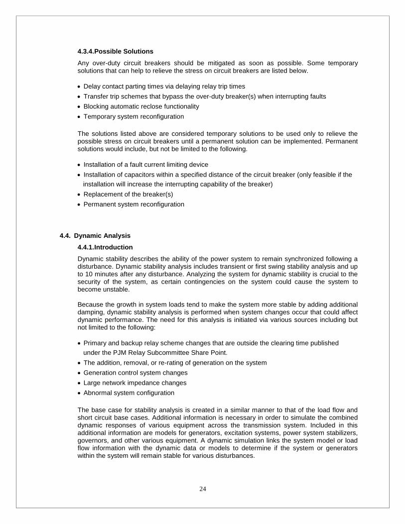
Ring Bus4.3.3.2.
For a ring bus design, each breaker must be able to interrupt the greater of the totalavailable fault current at the bus less the contribution from the equipment between thebreaker under study and the adjacent breaker on either side (assuming the breaker understudy is the last to open). For breaker B1 in the figures below, this would be the total faultcurrent at the bus less the current from either circuit 1 or circuit 2. Again, for the ring busdesign, the available fault current needs to be checked with the circuit breaker(s) at theopposite end of the faulted line, both open and closed.
Figure 6 Ring Bus Figure 7 Ring Bus
Figure 8 Ring Bus Figure 9 Ring Bus

21
Breaker & a Half4.3.3.3.
For a breaker & a half design, each breaker must be able to interrupt the total availablefault current at the bus. For this analysis, the breaker under study is assumed to be thelast to open. Each tie-breaker must be able to interrupt the greater of the total availablefault current at the bus less the contribution from the equipment in either bay.
Figure 10 True Breaker & a Half
Breaker & a Half with Connections on Bus4.3.3.4.
For a breaker & a half station with connections on either bus, each bus breaker must beable to interrupt the greater of (1) the total available fault current at the bus less thecontribution from the equipment connected to the bus or (2) the total available fault currentat the bus less the contribution from the equipment contained within the bay of the breakerunder study. Each tie breaker must be able to interrupt the greater of the total availablefault current at the bus less the contribution from the equipment in either bay.

22
Figure 11 Breaker & a half w/ transformers or other connections on bus
Figure 12 Breaker & a half w/ transformers or other connections on bus

23
Figure 13 Breaker & a half w/ transformers or other connections on bus
Figure 14 Breaker & a half w/ transformers or other connections on bus
24
4.3.4.Possible Solutions
Any over-duty circuit breakers should be mitigated as soon as possible. Some temporarysolutions that can help to relieve the stress on circuit breakers are listed below.
Delay contact parting times via delaying relay trip times Transfer trip schemes that bypass the over-duty breaker(s) when interrupting faults Blocking automatic reclose functionality Temporary system reconfiguration
The solutions listed above are considered temporary solutions to be used only to relieve thepossible stress on circuit breakers until a permanent solution can be implemented. Permanentsolutions would include, but not be limited to the following.
Installation of a fault current limiting device Installation of capacitors within a specified distance of the circuit breaker (only feasible if the
installation will increase the interrupting capability of the breaker) Replacement of the breaker(s) Permanent system reconfiguration
Dynamic Analysis4.4.
4.4.1.Introduction
Dynamic stability describes the ability of the power system to remain synchronized following adisturbance. Dynamic stability analysis includes transient or first swing stability analysis and upto 10 minutes after any disturbance. Analyzing the system for dynamic stability is crucial to thesecurity of the system, as certain contingencies on the system could cause the system tobecome unstable.
Because the growth in system loads tend to make the system more stable by adding additionaldamping, dynamic stability analysis is performed when system changes occur that could affectdynamic performance. The need for this analysis is initiated via various sources including butnot limited to the following:
Primary and backup relay scheme changes that are outside the clearing time publishedunder the PJM Relay Subcommittee Share Point. The addition, removal, or re-rating of generation on the system Generation control system changes Large network impedance changes Abnormal system configuration
The base case for stability analysis is created in a similar manner to that of the load flow andshort circuit base cases. Additional information is necessary in order to simulate the combineddynamic responses of various equipment across the transmission system. Included in thisadditional information are models for generators, excitation systems, power system stabilizers,governors, and other various equipment. A dynamic simulation links the system model or loadflow information with the dynamic data or models to determine if the system or generatorswithin the system will remain stable for various disturbances.

25
Loads are modeled as constant power in loadflow analysis; however, during stability analysis,loads should be modeled as constant current for the real portion (MW) and constant impedancefor the reactive portion (MVAR) unless a representation is known that more specifically appliesto the system studied.
All base cases are developed by RF and PJM with information provided by generation owners.Case are made available to PJM and RF members. The worst case load level (light,intermediate, or peak) are utilized to study each scenario except when studies are initiated bybulk power operations with specific system conditions that need to be modeled.
The power system’s response to a disturbance is simulated to determine whether or not thesystem remains stable. In most cases, the output of the simulation is analyzed in graphicalform, either creating a power vs. angle curve or plotting system variables (angle, voltage,power, frequency, etc.) with respect to time.
The plot below illustrates a system disturbance that remains stable. In this simulation, a faultoccurred at time 0+ and the magnitude of the oscillations reduced in magnitude as timeincreased.
Two examples of unstable systems can be found below. Plot 2 illustrates a system disturbancethat causes sustained oscillations and Plot 3 illustrates a system disturbance that causesdynamic instability.
Plot 1 System Remaining Stable After Disturbance
Plot 2 System Experiencing Sustained Oscillations Plot 3 System Experiencing Dynamic Instability

26
4.4.2. Disturbances
Per NERC criteria, the stability of BGE’s and neighboring transmission systems must besustained without loss of load for all contingencies as described in section 4.4.1 including:
Three-phase fault with normal clearing Single phase-to-ground fault with a stuck breaker or any other cause for delayed clearing The loss of any single facility with no fault
For BGE, the system should also remain stable given the following disturbances:
Three-phase fault at a point 80% of the circuit impedance away from the station under studywith zone two clearing Failure of a generator Failure or all generation from one station Opening or closing of a transmission facility Loss of a large block of load Faulted circuit breaker
For all of the disturbances above, the system must maintain angle stability. In cases where thesystem is unstable, the system should be enhanced to improve stability as set forth in section4.4.4.
4.4.3.Performing the Analysis
BGE performs dynamic stability analysis utilizing the PSS/e Power System Simulation software.Base case load flows and dynamics data are obtained from PJM or RFRF and will include theBGE system in as much detail as possible with the neighboring systems as modeled by PJMand RFRF. When performing the analysis the most up-to-date information should be used. Thiswould include any recent enhancements to system models, generation models, or operatingtimes.
For all contingencies involving faults, the fault clearing times are of the utmost importance. Theamount of time it takes for a fault to clear has a direct impact on the stability of the system.
When performing dynamic stability analysis actual operating times should be obtainedwhenever possible. These times include zone one and zone two clearing times, backupclearing times, reclosing times, and auto-transfer times. The clearing times include the totalrelay trip times plus the longest probable breaker interrupting times. Whereas in short circuitanalysis we use the quickest possible total interrupting times to simulate worst case scenarios,for stability analysis, we assume the longest possible total interrupting times to simulate worstcase scenarios.
Often, transmission operations may request a stability analysis be performed for anycontingency given the system in an abnormal configuration. When these requests are made,care should be taken to modify the base case so that it is as similar as possible to the systemconfiguration under study. The load level, generation dispatch, and voltage control mechanismsshould be reviewed to create a study case as close as possible to what the system isexperiencing.

27
4.4.4.Possible Solutions
There are several ways to enhance system stability in the event that unstable conditions areidentified. Some are listed below.
Independent pole breakers The addition of power system stabilizers Shorten fault clearing times (primary or backup) – faster breaker Generation runback or trip schemes Limitation of generation output Addition of transmission lines Addition of transmission series capacitors Addition of transmission shunt capacitors Addition of dynamic reactive devices Schemes for the removal or transfer of load
An analysis of the system’s response to a disturbance that causes instability will provide anindication as to what system enhancements can be employed to attain stability. An economicanalysis must be performed to determine the best solution.
As a delivery company, BGE does not own generators to which it can make enhancements.BGE can only change the characteristics of the transmission system to make the system stable.PJM may direct those that control the generating stations to make changes to their units forstability problems and BGE may provide input to that process if the generating unit impactsBGE’s facilities.
Emergency Import Capability4.5.
NERC provides guidelines for defining terms and simulation techniques for use in thedetermination of transfer capability in its report Transmission Transfer Capability. (NorthAmerican Electric Reliability Council. Transmission Transfer Capability, May, 1995). Asestablished in the NERC document, the First Contingency Total Transfer Capability (FCTTC) isthe sum of normal base transfers and the First Contingency Incremental Transfer Capability(FCITC). Normal base power transfers are those power transfers that are considered to be partof normal base system loading for the condition being analyzed. FCITC is defined as theamount of power, incremental above normal base power transfers that can be transferred overthe transmission network in a reliable manner. The BGE transmission system’s EmergencyImport Capability is determined according to the NERC FCTTC criteria and definition.
If any two (or more) companies are geographically proximate and tightly interconnected, it isoften more appropriate to examine Emergency Import Capability on a geographic rather than astrictly company basis. As neighboring companies regularly share the same transmission tielines in bringing power into their respective systems, import analysis for the combined systemsmust be examined. BGE and the Potomac Electric Power Company (PEPCO) form such anidentifiable subarea within PJM. Because of this, emergency import capability should bedetermined for the BGE and PEPCO combined area as well as the BGE area alone.
Annually, the ability of the PJM transmission network to deliver power to load is assessed. Aspart of that analysis, an assessment is conducted to demonstrate the deliverability of theaggregate of PJM capacity resources to the load for each predefined electric sub-area withinthe PJM control area. This analysis ensures that there is an adequate balance of generationresources within the sub-area and import capability into the sub-area to maintain the sub-area’sdefined reliability criteria. Conversely, the deliverability of generation within each sub-area tothe aggregate PJM load is also assessed. This test is designed to ensure that there is sufficient

28
export capability out of each sub-area such that generation is available to serve loadthroughout the PJM control area.
BGE, in coordination with the PJM Office of the Interconnection, will plan its transmissionsystem such that there will be sufficient import capability into the BGE and combined BGE andPEPCO sub-region so that the probability of occurrence of load exceeding the availablecapacity resources shall not be greater, on the average, than one day in ten years.
PJM plans its capacity reserve requirements for the entire pool to meet the same one day in tenyear reliability level. Each year, a stochastic analysis of the system is performed using theGEBGE (or a program approved and accepted by the PJM Planning Committee) GenerationReliability Program to determine the capacity reserves required for PJM to attain its designreliability level. This program does not, however, consider transmission constraints within thePJM system. A further analysis determines the Capacity Emergency Transfer Objective (CETO)for each member company and all applicable subsystems. This analysis establishes the actuallevel of transfer capability required for each transmission subsystem.
Both analyses performed assume planned capacity resources based on the latest published in-service dates. They consider the quantity and location (external or native to the subsystem) ofthe capacity resources, expected availability of resources, forecast load levels and annual loadshapes, the availability of active load management programs, and load-forecast uncertainties.Forced outage rates are based on five-year historical rates used for reliability planning.
CETO analysis uses the GEBGE reliability program (or a program approved and accepted bythe PJM Planning Committee) to establish the relationship between Sub-regional TransferCapability and risk of Sub-regional loss-of-load solely due to insufficient transfer capability. Thisrisk assessment is independent of the risk analysis of PJM loss-of-load due to insufficientcapacity reserves. This risk is usually expressed in a reliability index (R.I.) of years ofexperience per day of interruption. The PJM accepted level is one day in 25 years (or 0.04 daysper year). This actually means that, on the average, one interruption will occur for every 25years of operating experience within the sub-region due to insufficient transfer capabilitybetween the sub-region and the remainder of PJM.
The second part of the emergency import capability analysis involves the use of load flowanalysis to calculate the level of Emergency Import Capability available, without interrupting orcurtailing existing and planned firm transmission services, to deliver external capacity resourcesand emergency capacity assistance into the system. The results of this analysis give theCapacity Emergency Transfer Limits (CETL).
In order to meet the import capability criteria, the CETL value must be greater than or equal tothe corresponding CETO value for both the BGE and combined BGE and PEPCO subareasover the transaction period.
The load flow base case used for CETL determination is constructed the same way as the loadflow used in CETO analysis, except for the following changes which are required in order tocreate a capacity emergency in the sub-area and thus a resulting capacity transfer from theinterconnected system into the sub-area.
CETL testing has all sub-area loads set to the LAS diversified accounting peak loads.Generation is forced out across the PJM System in proportion to forced outage rates. Sub arealoads are set to 105% of the non-diversified expected peak load with the amount above theaccounting peak at an 80% power factor. The most critical, usually the largest, unit in each subarea is forced out for each study area’s CETL analysis. The need for emergency power importsis simulated by outaging additional capacity resources in the sub area. The capacity shortfall issupplied by the remainder of the pool or, if necessary, by other control areas without regard foreconomics.

29
Emergency imports are increased until limited by system voltage or thermal capability. The sub-area’s power import at this transfer level is the sub area’s CETL. The tests performed toevaluate the CETL are those set in PJM Manual M14-B
..The PJM Interconnection is responsible for performing the CETO/CETL tests as part of routineanalysis of resource deliverability and PJM transmission adequacy assessments. BGEperforms the CETL tests for study purposes.

30
Planning Design Guidelines for System Expansion5.Substation Expansion Philosophy5.1.
To ensure consistency of substation design, BGE has developed expansion guidelines. Theseguidelines are intended to enhance BGE and PJM operations and support a dependableoperating environment. BGE will use these guidelines in the design and construction of newsubstations and they will also serve as a guide for the expansion or modification of existingsubstations. While it is neither practical nor cost-justifiable to immediately rebuild all existingsubstations to these new standards, whenever modifications are made to existing substations,BGE will move the substation configurations toward these new standards. Although severalstation configurations are allowed, the station configuration may initially be required to be builtfor breaker and half based on load flow and technical analysis. Consideration for transition to theultimate configuration will be factored into the initial build configuration decision.
Situations may arise where physical space limitations or other considerations may require avariation from these standards in the design of a station. To preserve the physical space neededfor the expansion of the transmission substation, distribution facilities should not be placed inareas allocated for transmission. Transmission equipment such as transformers, capacitors,towers should not be placed in space dedicated for future expansion of substation breaker bays.
Circuit breakers can be utilized in place of circuit switchers when deemed necessary and wherecircuit switchers are normally required. When a circuit breaker is required or deemed necessary,a single pole breaker can be utilized when greater reliability is needed.
Extra High Voltage (EHV) 500kV Reliability Criteria and Practice5.2.
The BGE substation expansion philosophy for the Extra High Voltage (EHV) system is intendedto provide the EHV system with the highest level of reliability of all voltage classes. This isbecause a disturbance on the 500 kV system can affect the greatest number of customers sincethis system has the highest load delivery capability. Additionally, such disturbances have thegreatest potential for propagating to adjacent transmission systems. In the event of a blackout,the EHV system must be able to support system restoration efforts in the shortest possible time.
The following design criterion applies to all BGE 500 kV substation installations:
Each element (Line or Transformer) must be separated by a circuit breaker to ensure systemdisturbances are minimized A faulted element must not result in the loss of an additional element A failed bus breaker or a bus fault does not result in the loss of an additional element During maintenance, no additional transmission elements will be taken out of service except for
the element being maintained When constructing a two breaker bay, all six of the associated disconnect switches are required
to minimize outage duration during the installation of the remaining tie breaker. A ring configuration is acceptable with three element designs interconnecting any combination
of lines and transformers. A four element ring is acceptable only if two of the elements aretransformers (Figure 9) No elements may connect to a bus without a circuit breaker Relay protection must comply with applicable BGE standards and PJM standards and
requirements as published by the Relay Subcommittee Transmission lines with more than two relay terminals are not permitted. For application of this
requirement a terminal is considered to be any location where relays and inter-station

31
communications must be installed in order to achieve coordinated protection that meets therequirements of BGE standard EPB-13006 Line disconnect switches are required on all transmission line, transformer and generator
connections to the substation All new 500 kV equipment shall be rated for a minimum of 4000A continuous current and 63kA
interrupting capability
In practice, BGE substation expansion of the EHV system is based on breaker and a halfconfigurations with all elements terminating between breakers with no elements connecteddirectly to the bus as shown in Figures 15, 16 and 17. These substation designs are standarddesigns used throughout the utility industry because of its high reliability and improvedoperability. This high level of reliability is necessary since planning reliability criteria includesmodel simulations of double contingency outages, tower outages and breaker failure.
Although the designs shown in figures 15, 16 and 17 are generally required for EHV installations,ring bus configurations are acceptable for three or four element EHV substations (Figures 18and 19). This is permitted when no more than four elements are connected at a substation, andmultiple outages will not result in a “split” station. When more than four elements interconnect ata station, the station design must evolve to a breaker and a half configuration to avoid suchstation “splits.”
Figure 15Typical 500 kV four-element breaker and a half
switching station design
Figure 16Typical 500 kV five-element breaker and a half switching station designs
Figure 17Typical larger 500 kV breaker and a half switching station design

32
High Voltage (230 kV) Reliability Criteria and Practice5.3.
BGE’s High Voltage (HV) system includes all 230 kV and 115 kV facilities. The BGE 230 kVtransmission system is designed to provide a secure and reliable supply of power to the BGE115 kV system connections to facilitate the transport of power to load areas. HV relay protectionmust be redundant and in compliance with PJM Relay Subcommittee requirements.
5.3.1. 500/230 kV Substations and 230 kV Switching Stations
The following design criterion applies to all BGE 500/230 kV substations and 230 kV switchingstation installations:
Each element (Line or Transformer) must be separated by a circuit breaker to insure systemdisturbances are minimized A faulted element must not result in the loss of an additional element A failed bus breaker or bus fault does not result in the loss of an additional element During maintenance, no additional transmission element will need to be taken out of service
except for the element under repair When constructing a two breaker bay, six disconnect switches and wire connections should be
installed to minimize the outage duration during the installation of the remaining breaker A ring configuration may be acceptable if the station has only three or four elements All elements that connects to a ring shall have associated disconnect switches Relay protection must comply with applicable BGE standards and PJM standards and
requirements as published by the Relay Subcommittee Transmission lines with more than two relay terminals are not permitted. For application of this
requirement a terminal is considered to be any location where relays and inter-stationcommunications must be installed in order to achieve coordinated protection that meets therequirements of BGE standard EPB-13006 For a transformer connected directly to a bus, there will be a separate zone of protection to
indicate an internal transformer fault
Figure 18Typical 500 kV three-element ring designs
Figure 19Typical 500 kV four-element ring designs

33
Low side of a 500-230 kV transformer can connect to the 230 kV bus (Figures 22 and 23) Line disconnect switches are required for terminations at substations for underground circuits
and transformers The ring configuration and a two bay breaker and a half configuration must have line
disconnects There should not be more than four elements for a two bay breaker and a half or a ring
configurationExpansion of BGE 230 kV-switching stations and substations is based on a breaker and a halfconfigurations as shown in figures 20-23. Similar to the 500 kV switching stations, ringconfigurations as shown in Figures 24 and 25 are allowed for three and four elementinstallations.
Figure 20Typical 230 kV four-element breaker and half
switching station design
Figure 22Typical 500/230 kV four and five element substation design
Figure 21Typical 230 kV four-element breaker and half
substation design
Figure 23Expanded 500/230 kV switching station to full breaker and
half station

34
5.3.2. 230/115 kV Substations
All 230/115 kV substations must be designed to provide sufficient reliability to the 115 kVsystem while not appreciably decreasing 230 kV network reliability. The configuration in Figure26 is designed to minimize 230kV substation fault levels while maintaining a reliabletransmission system. Refer to Figures 21, 24, 25 and 27 to see other configurations for 230/115kV substations.
The following design criterion applies to all BGE 230/115 kV substation installations:
Each element (Line or Transformer) must be separated by a circuit breaker to ensure systemdisturbances are minimized A 230 kV line outage must not drop any 230/115 kV transformers During maintenance , no additional transmission element will be need to be taken out of service
except for the element under repair When constructing a two breaker bay, six disconnect switches and wire connections should be
installed to minimize the outage duration during the installation of the remaining breaker. All elements that connect to a ring should have associated disconnect switches when feasible Transmission lines with more than three relay terminals are not permitted. For application of
this requirement a terminal is considered to be any location where relays and inter-stationcommunications must be installed in order to achieve coordinated protection that meets therequirements of BGE standard EPB-13006 Relay protection must be redundant and in compliance with BGE and PJM Relay
Subcommittee requirements Line disconnect switches are required for terminations at substations for underground circuits
and transformers 230 kV line breakers should open to isolate the fault on the transformer. Upon the opening of
the circuit switchers, the line breakers should automatically close restoring the line. Thepreferred configuration is to have a three breaker ring station.
Figure 24Typical 230 kV three-element ring designs
Figure 25Typical 230 kV four-element ring design

35
5.3.3. 230/34.5 kV and 230/13.8 kV Substations
On the BGE system, 230/34.5 kV and 230/13.8 kV substations primarily feed radial distributionload. The design objective of these substations is to reliably serve distribution load whileisolating the disturbances on the distribution system and preventing them from propagating tothe 230 kV system.
The following design criterion applies to all 230/34.5 kV and 230/13.8 kV substations:
A 230 kV breaker must be installed when connecting a distribution substation to the 230kVsystem A transformer lead fault resulting in a momentary interruption of the thru transmission path is
acceptable when automatic restoration of thru transmission is applied During maintenance, no additional transmission will be taken out of service except the element
being maintained Relay protection must be redundant and in compliance with BGE and PJM Relay
Subcommittee requirements Line disconnect switches are required for terminations at substations for underground circuits Every transformer shall have a dedicated transformer isolation circuit switcher
Figure 26Typical 230/115 kV substation design
Figure 27Three breaker ring station
Figure 28Typical 230/34.5 kV and 230/13.8 kV substation design

36
High Voltage (115 kV) Reliability Criteria and Practice5.4.
Expansion of 115 kV switching substations is based on a breaker and a half configuration withsome variations allowed similar to the 230 kV switching station configurations. The concept is toprovide a secure and reliable 115 kV switching substation that will facilitate the transport ofpower within the local BGE region and provide backup to the local load areas.
The 115 kV transmission system plays the major role of supplying power to distribution stations.Often 115 kV stations may function as both a switching station and a supply of power to thedistribution system. For these stations, the connection of a high voltage transformer directly tothe 115 kV bus is required. Due to the relatively high system fault levels on the BGE system, thenumber of substations with a solid 115 kV bus is carefully considered.
in support of reliability and system security, the transmission protection system consists of relaysand circuit breakers that are designed to have zones of redundant protection. During brief timesof protection upgrades or testing, the 115 kV system may be configured with multiple elementsunavailable.5.4.1.115 kV switching Substations
Expansion of BGE 115 kV switching substations is based on a breaker and a half configurationas shown in Figure 29; however, variations similar to the 230 kV switching stationconfigurations are allowed for three and four element installations.
The following design criterion applies to a 115 kV breaker and a half substation:
Each element (Line or Transformer) must be separated by a circuit breaker to ensure systemdisturbances are minimized A faulted element must not result in the loss of an additional element A failed bus breaker or bus fault does not result in the loss of an additional element During maintenance, no additional element will be taken out of service except for the element
under repair The low side of a 230-115 kV transformer can connect to the 115 kV bus Transmission lines with more than three relay terminals are not permitted
For application of this requirement a terminal is considered to be any location where relays andinter-station communications must be installed in order to achieve coordinated protection thatmeets the requirements of BGE standard EPB-13006 Relay protection must be redundant and in compliance with BGE and PJM Relay
Subcommittee requirements Line disconnect switches are required for terminations at substations for underground circuits
and transformers Two Transformers can share a position in the bay but each transformer should be separated by
a circuit switcher

37
5.4.2. Downtown Baltimore 115 kV Substations
For 115 kV distribution substations that serve downtown Baltimore distribution transformers, thedisturbances on the distribution system should have minimum adverse effect on the 115 system(and in turn other distribution transformers). This is accomplished by the addition of a bussectionalizing breaker. In general, these stations carry high load levels of approximately 240MW by four 80 MVA 115/13.8 kV trans-formers as shown in Figure 30.
Two Breaker distribution station5.4.2.1.
The following design criterion applies to 115 kV stations feeding downtown Baltimoredistribution transformers with two 115 kV connections at each bus:
The loss of a 115 kV line or transformer should not propagate line outages beyond thenext station A bus or line fault should not result in more than one transformer out at a station Circuit switchers should be placed on the high side of a 115/13.8kV transformer to provide
isolation if the transformer from a line or other transformers Maintenance performed by opening a bus breaker and a subsequent line outage shall not
drop more than one 115 kV transmission line During maintenance no additional element should be taken out of service except for the
element under repair Relay protection should be redundant and in compliance with BGE and PJM Relay
Subcommittee requirements A 115kV breaker should be added if two transformers connect to the same line at a
substation Line disconnect switches are required for terminations at substations for underground
circuits and transformers
Figure 29Typical 115 kV switching station expanded to full breaker and half design

38
Three Breaker distribution station5.4.2.2.
Expansion of the urban Baltimore 115 kV distribution substation to accommodateadditional 115 kV lines is in Figure 31. This design shows a 115 kV station configured toact as two separate 115 kV ring stations. Similar to other BGE ring designs, these ringsshould be limited to no more than three lines.
The following design criterion applies to 115 kV stations feeding downtown Baltimoredistribution transformers with more than two 115 kV connections at each bus:
The loss of a 115 kV line or transformer should not propagate line outages beyond thenext station A bus or line fault should not result in more than one transformer out at a station Maintenance performed by opening a bus breaker and a subsequent line outage will not
drop an additional 115 kV transmission line of another substation During circuit breaker maintenance there should be no interruption of any 115 kV
transmission path Circuit switchers should be placed on the high side of a 115/13.8kV transformer to provide
isolation if the transformer from a line or other transformers. For maintenance, no additional element will be out except for the element under repair Relay protection must be redundant and in compliance with BGE and PJM Relay
Subcommittee requirements All elements that connect to a ring should have associated disconnect switches
Figure 30Typical 115 kV Downtown Baltimore Switching Station Serving Distribution Transformers

39
Four-element ring bus station5.4.2.3.
Expansion of the downtown Baltimore 115 kV transmission system may include theconnection of all four 115 kV lines to a station. The configuration used is a four-elementring shown in Figure 32. This ring is limited to four lines to avoid the potential of splitting astation into two disconnected sections resulting in complex operation that may occurduring maintenance and outages.
The following design criterion applies to 115 kV stations feeding downtown Baltimoredistribution transformers with a solid four-element ring bus:
The loss of a 115 kV line or transformer should not split the 115 kV station The loss of a 115 kV line or transformer should not propagate outages beyond the next
station A bus fault should result in the outage of no more than one 13.8 kV distribution
transformer at any station Maintenance performed by opening a bus breaker and a subsequent line outage should
not drop an additional 115 kV transmission line of another station. No more than four lines can terminate at this type of station Circuit switchers should be placed on the high side of a 115/13.8kV transformer to provide
isolation from a line or other transformers During circuit breaker maintenance there should be no interruption of any 115 kV
transmission path During maintenance no additional element should be out except for the element under
repair Relay protection must be redundant and in compliance with BGE and PJM Relay
Subcommittee requirements
Figure 31Typical 115 kV Downtown Baltimore Switching Station with Three-Element Ring Buses

40
Line disconnect switches are required for terminations at substations for undergroundcircuits and transformers All elements connected to a ring should have associated disconnect switches
5.4.3.Requirements for Substation Separation
When expansion of the 115 kV transmission system adds additional exposure to a transmissionline due to the addition of a line tap or multiple transformer taps, additional protection to thesubstation is required where exposure has increased. The need for additional line protectionmay also be required to improve transmission reliability to customers or the overall 115 kVsystem.
Generally, the additional line protection is provided by the installation of line circuit breakers onboth sides of the tapped line. These breakers reduce the added 115 kV transmission exposureintroduced by the line tap. Figure 33 shows an example of the addition of breakers to the basicBGE substation design of a non-downtown Baltimore 115 kV substation.
The preferred configuration is shown in Figure 34, by connecting the transmission lines in a ringconfiguration.
The following guidelines will be used to determine the situations where additional line protectionis required:
Tap extensions for overhead lines over one mile and for underground lines over two miles The total number of tapped substations on a 115 kV line exceeds three The total load lost for a double circuit tower outage exceeds 300 MW Special cases identified by a critical transmission line path or critical customer load BGE operations has a need based for improvement on operation or reliability issues There is an underground transmission line connected to overhead sections to improve the
ability to isolate overhead lines from underground cables
Figure 32Typical 115kV Downtown Baltimore Switching Station with a Four-Element Ring Bus

41
Additional Requirements for Interconnection Facilities5.5.
When a company seeks to interconnect with the BGE Transmission System, care must be takenso that disturbances initiated on one system do not propagate onto the other system. Therefore,BGE stations should be designed so that the interconnection is maintained for element outagesoccurring within BGE. Similarly, the connection of transmission, load or generation customersmust ensure that disturbances on customer facilities will not result in outages in the BGE system.
Because of the heightened need for the security of interconnection facilities and the need toprotect the BGE system from events on customer facilities, the following additional guidelinesapply to such facilities:
Isolation between BGE and the other company should be accomplished at a minimum with acircuit breaker BGE reliability and operability should not be comprised in any way due to non-BGE standard
equipment. BGE will also review the configurations based on reliability and operational issuesand modify the design for approval as needed. All equipment must meet BGE equipment standards if it is within a BGE substation or it is
operated by BGE Interconnection substations should be designed such that a bus outage or element outage
should not split a station or disconnect an interconnection facility Line disconnect switches are required for underground circuit terminations at substations and
when connected to the overhead sections New generators shall have a method of synchronizing so that BGE will not have to operate the
station breakers for generation operation
The following designs are acceptable for interconnection facilities:
Figure 33Example Substation Design Requiring Additional Breakers
Figure 34Example Substation Design Requiring Additional Breakers

42
Figure 35230kV Substation with Ring Interconnection
Figure 37115kV Substation with Ring and Interconnection
Figure 36230kV Substation Interconnections

43
Additional Requirements for 500 kV interconnection Facilities5.6.
The following criteria apply to all 500 kV substation installations:
In all arrangements each line or transformer, by itself, must occupy a single zone of protectionthat is bounded by circuit breakers. In breaker-and-a-half arrangements, each bus, by itself, must occupy a single zone of
protection bounded by circuit breakers. Substation designs must ensure that a failed breaker will result in the loss of no more than two
elements and will not electrically separate the remaining elements from each other All elements that connect to the ring shall have associated disconnect switches Three-breaker ring bus arrangements are permitted when the connected elements are limited
to three lines, or to two lines and a transformer Four-breaker ring bus arrangements are permitted when the connected elements are limited to
two lines and two transformers Ring bus designs should be physically and electrically constructed to permit the eventual
evolution of the station to a breaker-and-a-half arrangement when the station is expanded In ring bus designs, the station should be physically and electrically designed so that lines are
not terminated in positions that will ultimately evolve into busses. It is permissible to terminatetransformers in these positions
The following designs are acceptable for 500 kV interconnection facilities:
Figure 38115kV Substation Interconnection
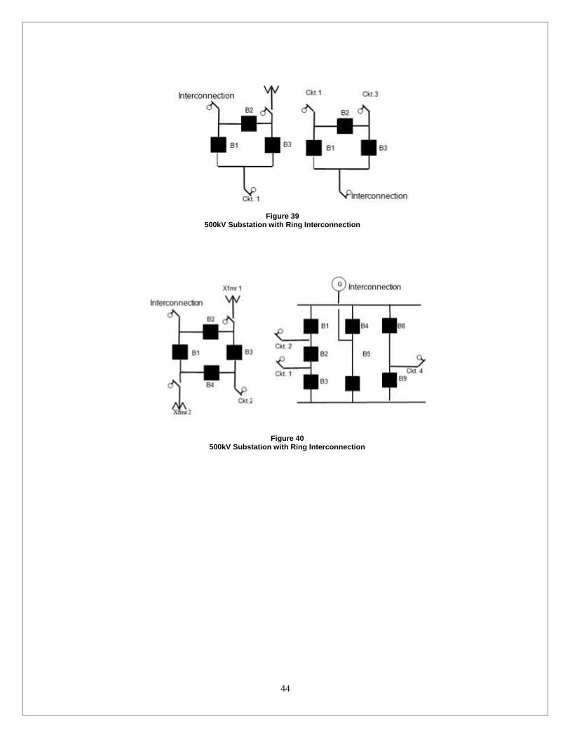
44
Figure 39500kV Substation with Ring Interconnection
Figure 40500kV Substation with Ring Interconnection
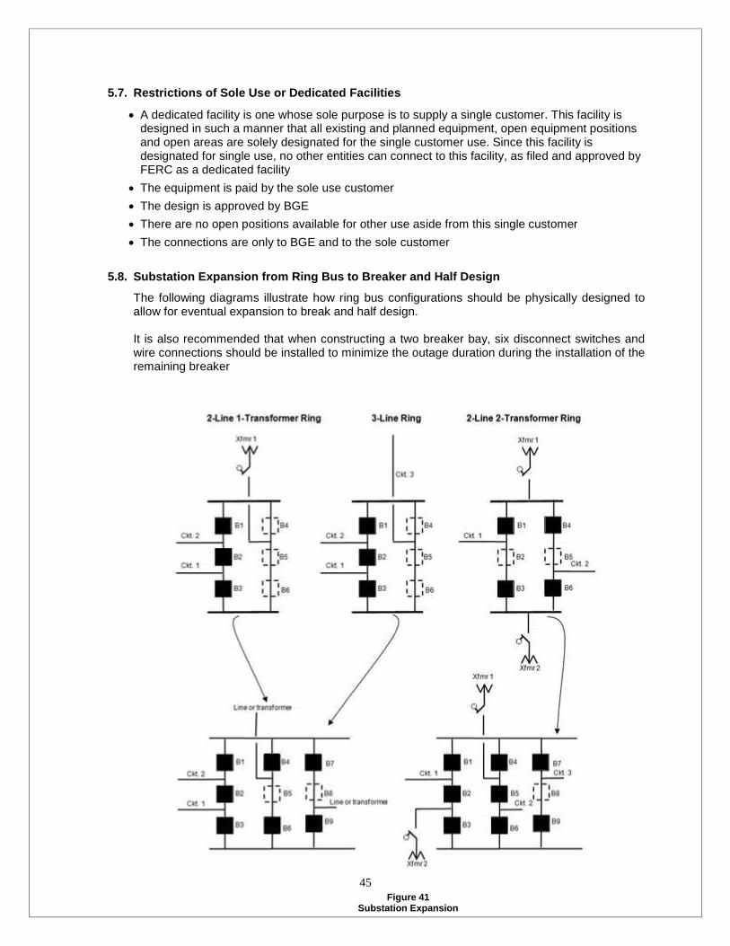
45
Restrictions of Sole Use or Dedicated Facilities5.7.
A dedicated facility is one whose sole purpose is to supply a single customer. This facility isdesigned in such a manner that all existing and planned equipment, open equipment positionsand open areas are solely designated for the single customer use. Since this facility isdesignated for single use, no other entities can connect to this facility, as filed and approved byFERC as a dedicated facility The equipment is paid by the sole use customer The design is approved by BGE There are no open positions available for other use aside from this single customer The connections are only to BGE and to the sole customer
Substation Expansion from Ring Bus to Breaker and Half Design5.8.
The following diagrams illustrate how ring bus configurations should be physically designed toallow for eventual expansion to break and half design.
It is also recommended that when constructing a two breaker bay, six disconnect switches andwire connections should be installed to minimize the outage duration during the installation of theremaining breaker
Figure 41Substation Expansion

46
Radial Criteria6.Introduction6.1.
No area supplied by two radial circuits should supply an excess of 300 MW of load during peakoperating conditions. The geographical footprint served by the substations supplied by the radialcircuits defines an area. Exceptions are allowable when distribution load transfers allow the totalload to be brought below the 300 MW level in emergency situations, however, this must notcause overloads on other transmission circuits or distribution feeders.
No radial transmission system should supply more load than the MVA level of the emergencyrating of the lowest rated radial circuit supplying the specific load. Given abnormal operation andcontingencies, this allows the load to be supplied with a reasonable amount of reliability.
Expansion6.2.
It is preferable to supply load via networked transmission, however, in certain situations, radialsupplies may be required. New overhead radial supplies must be justified by a joint studyperformed by transmission and distribution planners. A cost benefit analysis may be used tojustify a new radial supply.
In addition to the criteria applied to the current system, new radial supplies exposed to acommon mode failure should serve no more than 30,000 customers where restoration wouldrequire greater than four hours.
Other BGE Radial Transmission System Criteria6.3.
Please refer to BGE’s System Planning Procedures and Guidelines Manual. This documentpresents BGE’s philosophy pertaining to the expansion of radial transmission systems.

47
Remedial Action SchemeRASThis section was perviously referred to7.as ”Special Protection System (SPS)”
Introduction7.1.
Normal protective relaying systems typically sense faults on a given element and isolate thefaulted element. In general, a Remedial Action Scheme (RAS) is a protective relaying system orremedial action scheme that is designed to detect abnormal system conditions (not necessarilylimited to faults) and take automatic corrective action by controlling other facilities. The RASaction can be remote to the problem sensed and can include tripping of system elements,generation rejection, generator runback, load shedding, or other control actions.
Because RAS actions are not limited to the facility on which a disturbance is sensed, there is aninherent risk that misoperation will result in a failure to initiate the action required to realize thedesired outcome. These unanticipated conditions may pose a significant risk to the reliability ofthe transmission system. For this reason BGE is very judicious about the application of RemedialAction Schemes. A thorough technical analysis should be conducted as part of the approvalprocess before any RAS may be integrated into the BGE Transmission System. This process willhelp determine the potential for any negative impact to the transmission system reliability.
Allowable Uses for RAS7.2.
An RAS shall not be installed as a substitute for good system design or operating practices. RASimplementation shall be generally limited to providing protection for temporary conditions thatmay exist due to construction delays, unusual combinations of system demand and equipmentoutages or availability, or specific equipment maintenance outages. The decision to employ anRAS should take into account the complexity of the scheme, the consequences of misoperation,and the potential to interact with other RASs on the system.
Temporary RAS Installation7.3.
Mitigation of thermal problems for single element contingencies, two element contingencies, andmultiple facility contingencies will be allowed for temporary relief only. Allowable uses fortemporary RAS installation would include:
Providing protection during construction lags, i.e. to mitigate potential overloads on facilities thatwill be permanently mitigated by system enhancements in the current transmission plan. Providing protection during maintenance outages.
Installation of a permanent solution should be completed as soon as possible after theinstallation of a temporary RAS.
7.3.1.Restrictions on the Use of Temporary RAS Installations
The following restrictions on RAS installation and use are applicable to all applications withinthe BGE Transmission Zone:
Temporary RAS installations may be initiated through detection of overloaded equipmentonly if an evaluation is performed to assure that the RAS would not interact with other RASapplication such that it could pose a risk of cascading outages.
An RAS installed to address a voltage criteria violation may only be used as a temporaryinstallation. Any RAS used for voltage drop criteria violation shall be designed with sufficient

48
redundancy such that the RAS is capable of performing its intended function while itselfexperiencing a single component failure.
No equipment overload, instability, or voltage problems beyond the facility the RAS wasintended to protect may be caused by the operation of the RAS.
Care should be taken to prevent unintended interaction between different RASs. Unlessspecifically designed or evaluated to work together no more than one RAS may employ thesame monitored condition or mitigating action except for functional redundancy of aseparate RAS.
An RAS time delay (if any) shall coordinate with all other short-time limitations withinapplicable loadings.
Permanent RAS Installation7.4.
An RAS may be installed permanently on BGE’s transmission system only for the mitigation ofextreme disturbances. Allowable uses for permanent RAS installations would include providingprotection against:
The loss of all lines of a certain voltage emanating from a single substation. The loss of all circuits in a single right-of-way. The loss of all generation at any one station. The loss of a large load center.
7.4.1.Restrictions on Permanent RAS Use
The following restrictions on RAS installation and use are applicable to all permanentapplication within the BGE Transmission Zone:
An RAS may not include the shedding of load as part of the remedial scheme unless for themitigation of an extreme disturbance. All permanent RASs shall be initiated by the loss of a physical facility and may not be initiated
through detection of overloaded equipment. An RAS may not be used as a permanent solution to mitigate a voltage criteria violation since
failure of the RAS to operate would not permit other timely action to be taken to protect againstthe voltage criteria violation. Permanent relief of stability problems through the installation of an RAS is not allowed for any
contingencies. No equipment overload, instability, or voltage problems beyond the facility the RAS was
intended to protect may be caused by the operation of the RAS. No equipment overload, instability, or voltage problems beyond the facility the RAS was
intended to protect may be caused by the misoperation or failure of the RAS to operate whendesired. Care should be taken to prevent unintended interaction between different RASs. Unless
specifically designed or evaluated to work together no more than one RAS may employ thesame monitored condition or mitigating action except for functional redundancy of a separateRAS. An RAS time delay (if any) shall coordinate with all other short-time limitations within applicable
loadings.

49
RAS Design & Planning7.5.
The design and planning for the installation of any RAS should ensure reliable systemperformance and operation. This requires close coordination between system protection andtransmission planning engineers.
In all RAS installations, the RAS must be physically located at the same site as the facility beingaltered. If the facility being monitored is at a remote location, redundant communication pathsmust be supplied between the monitored facility and the RAS.
7.5.1.Design
The design of any RAS should ensure that the system will be both dependable and secure.Dependability ensures that the RAS will operate as intended, and when needed. Securityensures that the RAS will not operate when not intended.
Dependability7.5.1.1.
Each RAS shall be designed with redundancy so that any single element failure will notprevent the RAS from operating when required. Redundancy may be obtained throughphysical or functional duplication.
Security7.5.1.2.
Each RAS shall be designed so that any failure of an internal device of the RAS will notcause the RAS to operate when not required.
Planning7.6.
The system shall be planned so that misoperation will not cause cascading outages.Misoperation includes: operation without an initiating incident, partial operation, slow operationor non-operation during an initiating event. Each RAS shall be coordinated with other protectionand control systems including those of neighboring transmission systems.
RASs shall be analyzed every five years to ensure misoperation will not cause adverse effectssuch as cascading outages. Identification of such effects will require replacement of the RASwith system enhancements.