Embed Size (px)
Citation preview
TRANSNET PIPELINES
PCS Upgrade Project Document Number Rev Page
RFI Technical Specification H354086-00000-300-078-0001 0 1 of 35
PCS Upgrade Project
RFI Technical Specification
DOCUMENT APPROVAL PROCESS
NAME POSITION/MEETING NO. SIGNATURE DATE
Originator Stuart Florence Hatch – Senior Control Engineer
Approver Alan Parsons TPL Manager – MC&I
Original date 2017-04-19
Effective date 2017-05-17
TRANSNET PIPELINES
PCS Upgrade Project Document Number Rev Page
RFI Technical Specification H354086-00000-300-078-0001 0 2 of 35
REVISION REVIEW RECORD
Rev NAME POSITION/MEETING NO. SIGNATURE DATE
0
Doc Status
Hatch Review
Hatch Approve
TPL Review
TPL Accept
1
Doc Status
Hatch Review
Hatch Approve
TPL Review
TPL Accept
2
Doc Status
Hatch Review
Hatch Approve
TPL Review
TPL Accept
3
Doc Status
Hatch Review
Hatch Approve
TPL Review
TPL Accept
4
Doc Status
Hatch Review
Hatch Approve
TPL Review
TPL Accept
5
Doc Status
Hatch Review
Hatch Approve
TPL Review
TPL Accept
TRANSNET PIPELINES
PCS Upgrade Project Document Number Rev Page
RFI Technical Specification H354086-00000-300-078-0001 0 3 of 35
Page 3 of 35 Originator: Stuart Florence Original date: 2017-04-19 Always refer to the electronic copy for the latest version.
TABLE OF CONTENTS
1. Purpose ................................................................................................................................. 5
2. Scope and Applicability ........................................................................................................ 5
3. Document Usage .................................................................................................................. 5
4. References ............................................................................................................................ 6
4.1 TPL Applicable Specifications and Standards .......................................................................... 6 4.2 Other Applicable Specifications and Standards ....................................................................... 6
5. Abbreviations And Definitions .............................................................................................. 7
5.1 Abbreviations ....................................................................................................................... 7 5.2 Definitions ........................................................................................................................... 8
6. Process Control, Metering and Pipeline Monitoring Systems Overview .............................. 9
6.1 Background ......................................................................................................................... 9 6.2 General ............................................................................................................................... 9 6.3 Execution Strategy ............................................................................................................. 10 6.4 Site Details ........................................................................................................................ 11 6.5 RFI Modules ...................................................................................................................... 12
7. Critical Requirements .........................................................................................................13
8. System Module 1: Process Control System ........................................................................14
8.1 Overview ........................................................................................................................... 14 8.2 Critical Requirements ......................................................................................................... 15 8.3 Module Requirements ......................................................................................................... 16
8.3.1 General .................................................................................................................... 16 8.3.2 Control ..................................................................................................................... 16 8.3.3 Alarming ................................................................................................................... 17 8.3.4 Interfaces ................................................................................................................. 17 8.3.5 Data Archiving .......................................................................................................... 17 8.3.6 Development ............................................................................................................ 17 8.3.7 System Performance ................................................................................................. 17 8.3.8 Security .................................................................................................................... 18 8.3.9 Maintenance and Upgrades........................................................................................ 18 8.3.10 Replay ...................................................................................................................... 18 8.3.11 HMI Trainer/Simulation ............................................................................................. 19 8.3.12 Proof of Concept Workshop ....................................................................................... 19
8.4 Capability .......................................................................................................................... 20 8.4.1 Operational Data Warehouse ..................................................................................... 20 8.4.2 Terminal Management ............................................................................................... 20
9. System Module 2: Custody Metering ..................................................................................22
9.1 Overview ........................................................................................................................... 22 9.2 Metering Process Equipment ............................................................................................... 22 9.3 Scope of RFI ...................................................................................................................... 22 9.4 Critical Requirements ......................................................................................................... 23 9.5 Module Requirements ......................................................................................................... 24
9.5.1 General .................................................................................................................... 24 9.5.2 Certification and Approvals ........................................................................................ 24 9.5.3 Alarming ................................................................................................................... 24 9.5.4 Interfaces ................................................................................................................. 25 9.5.5 Archiving .................................................................................................................. 25
TRANSNET PIPELINES
PCS Upgrade Project Document Number Rev Page
RFI Technical Specification H354086-00000-300-078-0001 0 4 of 35
Page 4 of 35 Originator: Stuart Florence Original date: 2017-04-19 Always refer to the electronic copy for the latest version.
9.5.6 Reporting ................................................................................................................. 25 9.5.7 Development ............................................................................................................ 25 9.5.8 Performance ............................................................................................................. 25 9.5.9 Security .................................................................................................................... 26 9.5.10 Maintenance ............................................................................................................. 26 9.5.11 Proof of Concept Workshop ....................................................................................... 26
9.6 Capability .......................................................................................................................... 27 9.6.1 Metering Trainer ....................................................................................................... 27 9.6.2 Flow Computers ........................................................................................................ 27
10. System Module 3: PLMS .....................................................................................................28
10.1 Overview ........................................................................................................................... 28 10.2 Critical Requirements ......................................................................................................... 28 10.3 Module Requirements ......................................................................................................... 28
10.3.1 General .................................................................................................................... 28 10.3.2 Alarming ................................................................................................................... 28 10.3.3 Interfaces ................................................................................................................. 28 10.3.4 Archiving .................................................................................................................. 29 10.3.5 Development ............................................................................................................ 29 10.3.6 Performance ............................................................................................................. 29 10.3.7 Security .................................................................................................................... 29 10.3.8 Maintenance ............................................................................................................. 29 10.3.9 Proof of Concept ....................................................................................................... 29
10.4 Capabilities ........................................................................................................................ 29 10.4.1 Pressure Dynamic Tracking System ............................................................................ 30 10.4.2 Batch Tracking System .............................................................................................. 30 10.4.3 Pig Tracking System .................................................................................................. 30
11. Project Wide/Common Module ..........................................................................................31
11.1 Overview ........................................................................................................................... 31 11.2 Common Requirements ...................................................................................................... 31
11.2.1 Regulatory Compliance .............................................................................................. 31 11.2.2 General Quality ......................................................................................................... 31 11.2.3 Software Lifecycle Quality .......................................................................................... 31 11.2.4 Documentation ......................................................................................................... 31 11.2.5 Support/Lifecycle ...................................................................................................... 32 11.2.6 Project Experience .................................................................................................... 32 11.2.7 Project Execution ...................................................................................................... 33 11.2.8 Commissioning and Support ...................................................................................... 33 11.2.9 Ops Readiness Training ............................................................................................. 33 11.2.10 Maintenance Training ................................................................................................ 33 11.2.11 System Architecture .................................................................................................. 33 11.2.12 Localisation .............................................................................................................. 33
11.3 Common Capabilities .......................................................................................................... 34 11.3.1 E&I Design ............................................................................................................... 34 11.3.2 E&I Installation ......................................................................................................... 34 11.3.3 Panel Manufacture and Hardware Integration ............................................................. 34
12. Document Lifecycle Management ......................................................................................35
12.1 Revision History ................................................................................................................. 35 12.2 Comments Resolution ......................................................................................................... 35
TRANSNET PIPELINES
PCS Upgrade Project Document Number Rev Page
RFI Technical Specification H354086-00000-300-078-0001 0 5 of 35
Page 5 of 35 Originator: Stuart Florence Original date: 2017-04-19 Always refer to the electronic copy for the latest version.
1. Purpose
The purpose of this Request For Information (RFI) Specification document is to,
Detail the high level scope requirements for the Process Control, Custody Metering and
Pipeline Monitoring System(s) required to be deployed on Transnet Pipeline multi-product petroleum pipeline infrastructure,
Detail the core requirements which will establish the basis for selecting the Process
Control, Custody Metering and Pipeline Monitoring System(s),
Support identification of suitable Process Control, Custody Metering and Pipeline
Monitoring System(s) from the market.
2. Scope and Applicability
The system scope of this specification is,
Process Control System (PCS),
Custody Metering System (CMS).
Pipeline Monitoring System (PLMS),
The scope of the project includes the supply/provision of Process Control, Custody Metering and
Pipeline Monitoring System/s suitable for use on all Transnet Pipeline infrastructure.
Only systems that have an established/ and proven track record on multi-product petroleum
pipeline installations will be considered.
Once developed, the system/s shall be deployed to all Crude Oil Pipeline stations, from Fynnlands Intake Station to Coalbrook Delivery Station. Note that in addition to catering for
crude product deliveries, the Coalbrook station also caters for catpoly (component) product deliveries, avtur product intakes and multi-product through station pumping which is included in
the scope of works. The latter products are distributed via pipeline networks that are separate
to the Crude Oil Pipeline.
3. Document Usage
In this specification,
the word shall is to be understood as a mandatory requirement,
the word should as a preference,
the word may as a permissive (i.e. neither mandatory nor necessarily recommended),
and the word will as a declaration on behalf of something/ someone else.
The word should shall be treated as a requirement, although it is acknowledged that it may be
negotiated based on appropriate justification.
Text indicated as 'Note' does not form part of this specification. Notes aid the reader's understanding of the associated requirements.
TRANSNET PIPELINES
PCS Upgrade Project Document Number Rev Page
RFI Technical Specification H354086-00000-300-078-0001 0 6 of 35
Page 6 of 35 Originator: Stuart Florence Original date: 2017-04-19 Always refer to the electronic copy for the latest version.
4. References
4.1 TPL Applicable Specifications and Standards
No. Doc. No. Rev.
[1] Custody Metering User Requirements Specification TPL-TECH-I-M-SPEC-011 02a
[2] Control System User Requirements Specification TPL-TECH-I-C-SPEC-012 02d
[3] PCS Software Control Module Standard TPL-TECH-I-C-STD-013 01c
[4] Automation Standard PL723 4 (draft)
4.2 Other Applicable Specifications and Standards
No. Doc. No. Rev.
[5] Dynamic Measuring Systems for Liquids other than water
OIML R117-1 2007
[6] API Manual of Petroleum Measurement Standards -
Chapter 5: Metering Systems
Section 3: Measurement of Liquid Hydrocarbons by Turbine Meters
Section 5: Fidelity & Security of Flow Measurement Pulsed-Data Transmission Systems
API Chapter 5: Ed 4 2005
[7] RSA Trade Metrology Act 77 of 1973 Act 77 of 1973 1973
[8] RSA Legal Metrology Act 9 of 2014 Act 9 of 2014 2014
TRANSNET PIPELINES
PCS Upgrade Project Document Number Rev Page
RFI Technical Specification H354086-00000-300-078-0001 0 7 of 35
Page 7 of 35 Originator: Stuart Florence Original date: 2017-04-19 Always refer to the electronic copy for the latest version.
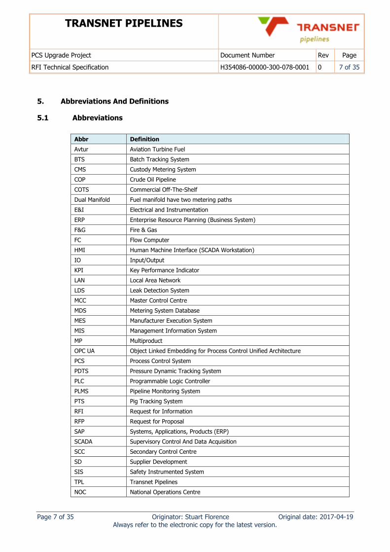
5. Abbreviations And Definitions
5.1 Abbreviations
Abbr Definition
Avtur Aviation Turbine Fuel
BTS Batch Tracking System
CMS Custody Metering System
COP Crude Oil Pipeline
COTS Commercial Off-The-Shelf
Dual Manifold Fuel manifold have two metering paths
E&I Electrical and Instrumentation
ERP Enterprise Resource Planning (Business System)
F&G Fire & Gas
FC Flow Computer
HMI Human Machine Interface (SCADA Workstation)
IO Input/Output
KPI Key Performance Indicator
LAN Local Area Network
LDS Leak Detection System
MCC Master Control Centre
MDS Metering System Database
MES Manufacturer Execution System
MIS Management Information System
MP Multiproduct
OPC UA Object Linked Embedding for Process Control Unified Architecture
PCS Process Control System
PDTS Pressure Dynamic Tracking System
PLC Programmable Logic Controller
PLMS Pipeline Monitoring System
PTS Pig Tracking System
RFI Request for Information
RFP Request for Proposal
SAP Systems, Applications, Products (ERP)
SCADA Supervisory Control And Data Acquisition
SCC Secondary Control Centre
SD Supplier Development
SIS Safety Instrumented System
TPL Transnet Pipelines
NOC National Operations Centre
TRANSNET PIPELINES
PCS Upgrade Project Document Number Rev Page
RFI Technical Specification H354086-00000-300-078-0001 0 8 of 35
Page 8 of 35 Originator: Stuart Florence Original date: 2017-04-19 Always refer to the electronic copy for the latest version.
Abbr Definition
VSD Variable Speed Drive
WAN Wide Area Network
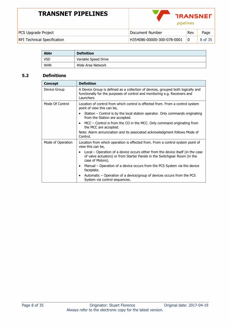
5.2 Definitions
Concept Definition
Device Group A Device Group is defined as a collection of devices, grouped both logically and functionally for the purposes of control and monitoring e.g. Receivers and Launchers
Mode Of Control Location of control from which control is effected from. From a control system point of view this can be,
Station – Control is by the local station operator. Only commands originating from the Station are accepted.
MCC – Control is from the CO in the MCC. Only command originating from the MCC are accepted.
Note: Alarm annunciation and its associated acknowledgment follows Mode of Control.
Mode of Operation Location from which operation is effected from. From a control system point of view this can be,
Local – Operation of a device occurs either from the device itself (in the case of valve actuators) or from Starter Panels in the Switchgear Room (in the case of Motors).
Manual – Operation of a device occurs from the PCS System via the device faceplate.
Automatic – Operation of a device/group of devices occurs from the PCS System via control sequences.
TRANSNET PIPELINES
PCS Upgrade Project Document Number Rev Page
RFI Technical Specification H354086-00000-300-078-0001 0 9 of 35
Page 9 of 35 Originator: Stuart Florence Original date: 2017-04-19 Always refer to the electronic copy for the latest version.
6. Process Control, Metering and Pipeline Monitoring Systems Overview
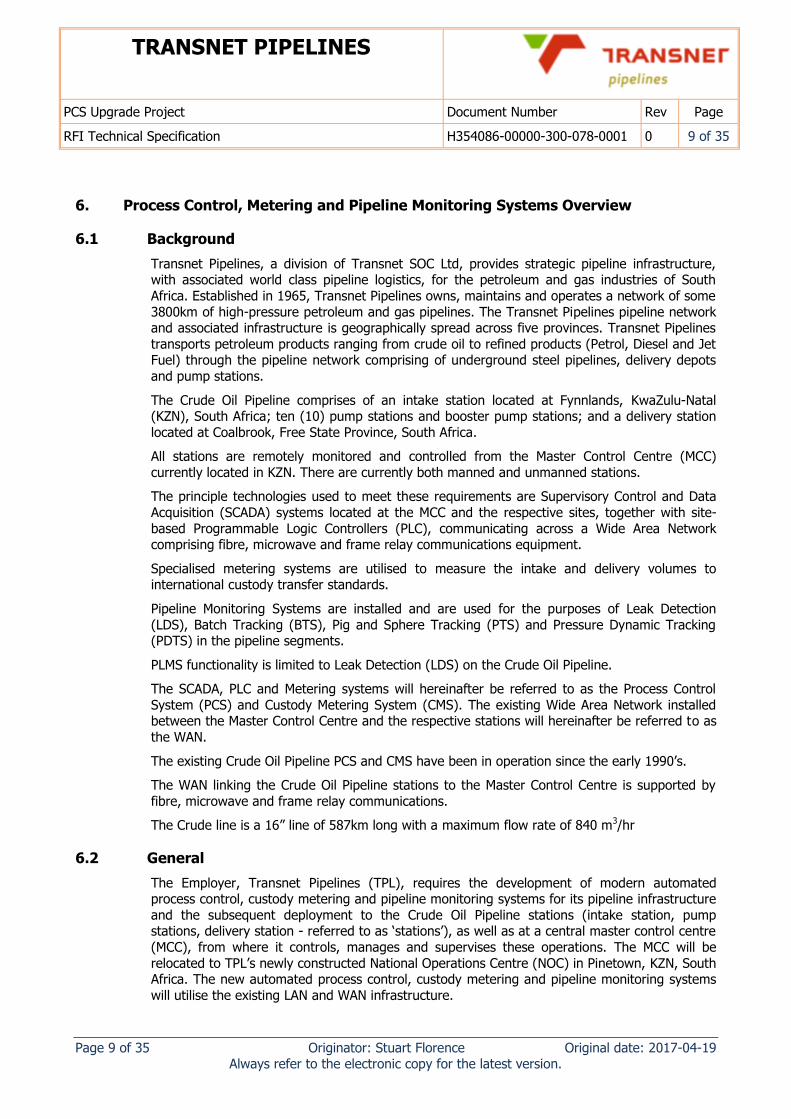
6.1 Background
Transnet Pipelines, a division of Transnet SOC Ltd, provides strategic pipeline infrastructure, with associated world class pipeline logistics, for the petroleum and gas industries of South
Africa. Established in 1965, Transnet Pipelines owns, maintains and operates a network of some
3800km of high-pressure petroleum and gas pipelines. The Transnet Pipelines pipeline network and associated infrastructure is geographically spread across five provinces. Transnet Pipelines
transports petroleum products ranging from crude oil to refined products (Petrol, Diesel and Jet Fuel) through the pipeline network comprising of underground steel pipelines, delivery depots
and pump stations.
The Crude Oil Pipeline comprises of an intake station located at Fynnlands, KwaZulu-Natal (KZN), South Africa; ten (10) pump stations and booster pump stations; and a delivery station
located at Coalbrook, Free State Province, South Africa.
All stations are remotely monitored and controlled from the Master Control Centre (MCC)
currently located in KZN. There are currently both manned and unmanned stations.
The principle technologies used to meet these requirements are Supervisory Control and Data
Acquisition (SCADA) systems located at the MCC and the respective sites, together with site-
based Programmable Logic Controllers (PLC), communicating across a Wide Area Network comprising fibre, microwave and frame relay communications equipment.
Specialised metering systems are utilised to measure the intake and delivery volumes to international custody transfer standards.
Pipeline Monitoring Systems are installed and are used for the purposes of Leak Detection
(LDS), Batch Tracking (BTS), Pig and Sphere Tracking (PTS) and Pressure Dynamic Tracking (PDTS) in the pipeline segments.
PLMS functionality is limited to Leak Detection (LDS) on the Crude Oil Pipeline.
The SCADA, PLC and Metering systems will hereinafter be referred to as the Process Control
System (PCS) and Custody Metering System (CMS). The existing Wide Area Network installed between the Master Control Centre and the respective stations will hereinafter be referred to as
the WAN.
The existing Crude Oil Pipeline PCS and CMS have been in operation since the early 1990’s.
The WAN linking the Crude Oil Pipeline stations to the Master Control Centre is supported by
fibre, microwave and frame relay communications.
The Crude line is a 16” line of 587km long with a maximum flow rate of 840 m3/hr
6.2 General
The Employer, Transnet Pipelines (TPL), requires the development of modern automated process control, custody metering and pipeline monitoring systems for its pipeline infrastructure
and the subsequent deployment to the Crude Oil Pipeline stations (intake station, pump stations, delivery station - referred to as ‘stations’), as well as at a central master control centre
(MCC), from where it controls, manages and supervises these operations. The MCC will be
relocated to TPL’s newly constructed National Operations Centre (NOC) in Pinetown, KZN, South Africa. The new automated process control, custody metering and pipeline monitoring systems
will utilise the existing LAN and WAN infrastructure.
TRANSNET PIPELINES
PCS Upgrade Project Document Number Rev Page
RFI Technical Specification H354086-00000-300-078-0001 0 10 of 35
Page 10 of 35 Originator: Stuart Florence Original date: 2017-04-19 Always refer to the electronic copy for the latest version.
The Coalbrook delivery station has been identified as a pilot station, where the newly developed automated process control and custody metering systems will be deployed first in order to
validate their performance, prior to further deployment. This station comprises the delivery point for product from the Crude Oil Pipeline, whilst also catering for Catpoly (component)
product deliveries, Avtur product intakes and multi-product through station pumping into other pipelines.
The aim of the project is to ensure that the Process Control System developed for TPL’s pipeline
infrastructure and its subsequent roll-out on the Crude Oil Pipeline has a sustainable useful service life until 2035.
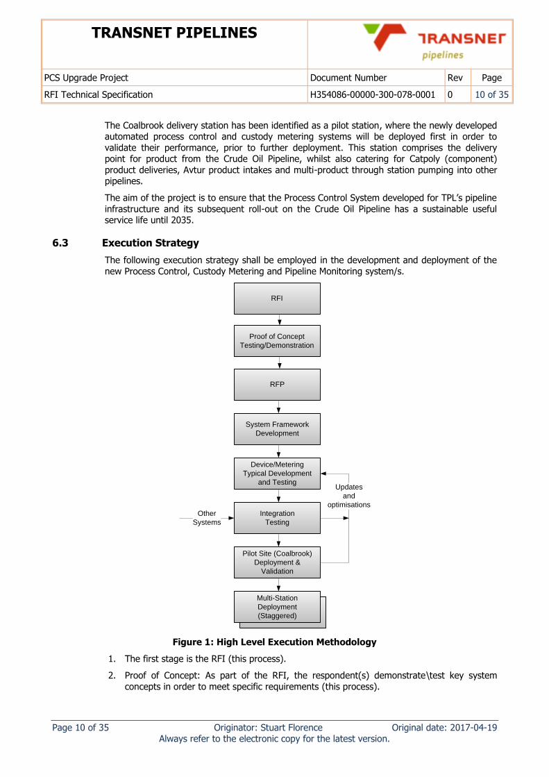
6.3 Execution Strategy
The following execution strategy shall be employed in the development and deployment of the
new Process Control, Custody Metering and Pipeline Monitoring system/s.
System Framework
Development
Device/Metering
Typical Development
and Testing
Integration
Testing
Pilot Site (Coalbrook)
Deployment &
Validation
Multi-Station
Deployment
(Staggered)
Updates
and
optimisations
Other
Systems
RFP
Proof of Concept
Testing/Demonstration
RFI
Figure 1: High Level Execution Methodology
1. The first stage is the RFI (this process).
2. Proof of Concept: As part of the RFI, the respondent(s) demonstrate\test key system
concepts in order to meet specific requirements (this process).
TRANSNET PIPELINES
PCS Upgrade Project Document Number Rev Page
RFI Technical Specification H354086-00000-300-078-0001 0 11 of 35
Page 11 of 35 Originator: Stuart Florence Original date: 2017-04-19 Always refer to the electronic copy for the latest version.
3. System framework development: This includes detailed design documentation, alarm concepts, control and hierarchy concepts, thin slices and demonstrations of functionality.
4. Device/metering typical development: This includes the development of detailed design documentation for interfacing to equipment, controlling devices, instrumentation and other
typicals which will form part of a library.
5. Integration Testing: This includes the validation and testing of all the modules of the
Process Control and Custody Metering systems as well as other systems in an integrated
fashion.
6. Pilot Site (Coalbrook) Deployment: This is the first site to validate the Process Control,
Custody Metering systems before rolling out to the Crude Oil Pipeline.
7. Multi-Station Roll out: This is the roll out of the full set of Process Control, Custody
Metering and Pipeline Monitoring systems across the Crude Oil Pipeline.
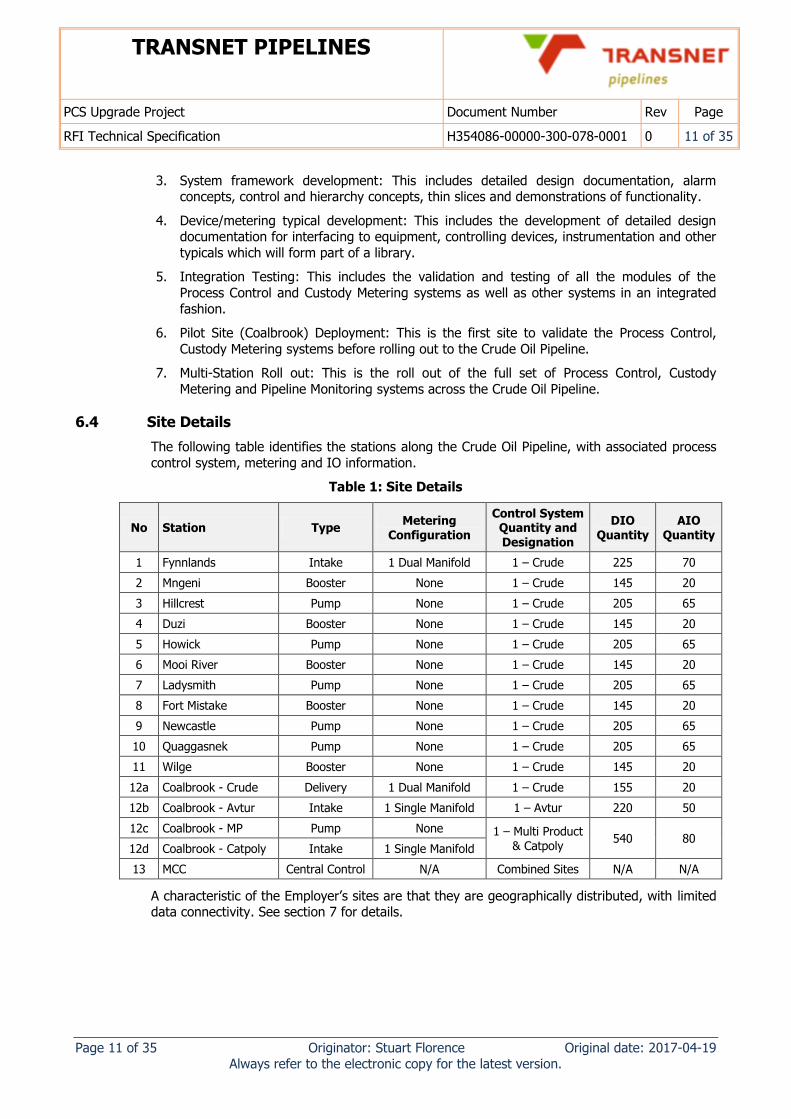
6.4 Site Details
The following table identifies the stations along the Crude Oil Pipeline, with associated process
control system, metering and IO information.
Table 1: Site Details
No Station Type Metering
Configuration
Control System Quantity and Designation
DIO Quantity
AIO Quantity
1 Fynnlands Intake 1 Dual Manifold 1 – Crude 225 70
2 Mngeni Booster None 1 – Crude 145 20
3 Hillcrest Pump None 1 – Crude 205 65
4 Duzi Booster None 1 – Crude 145 20
5 Howick Pump None 1 – Crude 205 65
6 Mooi River Booster None 1 – Crude 145 20
7 Ladysmith Pump None 1 – Crude 205 65
8 Fort Mistake Booster None 1 – Crude 145 20
9 Newcastle Pump None 1 – Crude 205 65
10 Quaggasnek Pump None 1 – Crude 205 65
11 Wilge Booster None 1 – Crude 145 20
12a Coalbrook - Crude Delivery 1 Dual Manifold 1 – Crude 155 20
12b Coalbrook - Avtur Intake 1 Single Manifold 1 – Avtur 220 50
12c Coalbrook - MP Pump None 1 – Multi Product & Catpoly
540 80 12d Coalbrook - Catpoly Intake 1 Single Manifold
13 MCC Central Control N/A Combined Sites N/A N/A
A characteristic of the Employer’s sites are that they are geographically distributed, with limited data connectivity. See section 7 for details.
TRANSNET PIPELINES
PCS Upgrade Project Document Number Rev Page
RFI Technical Specification H354086-00000-300-078-0001 0 12 of 35
Page 12 of 35 Originator: Stuart Florence Original date: 2017-04-19 Always refer to the electronic copy for the latest version.
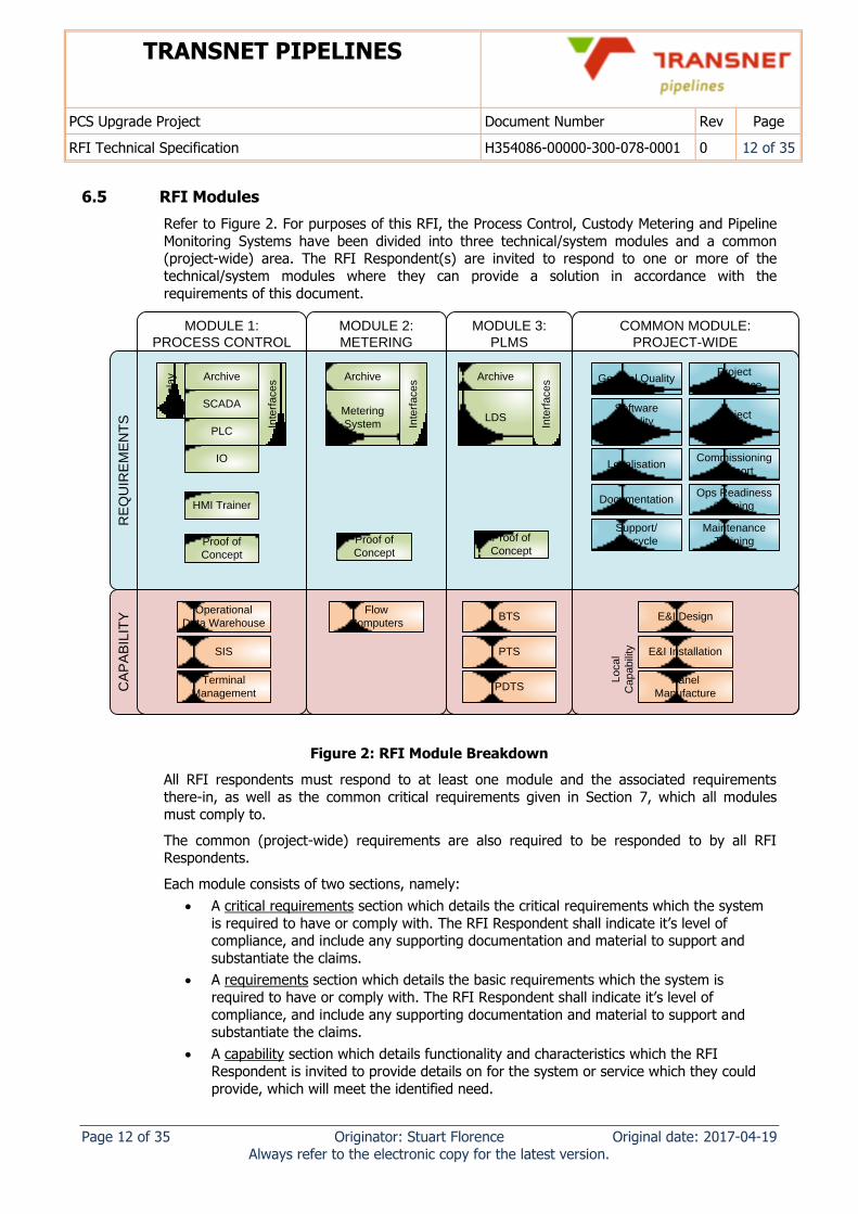
6.5 RFI Modules
Refer to Figure 2. For purposes of this RFI, the Process Control, Custody Metering and Pipeline
Monitoring Systems have been divided into three technical/system modules and a common (project-wide) area. The RFI Respondent(s) are invited to respond to one or more of the
technical/system modules where they can provide a solution in accordance with the
requirements of this document.
CA
PA
BIL
ITY
RE
QU
IRE
ME
NT
S
Archive
LDS
Inte
rfa
ce
s
Archive
SCADA
PLC
IO
Inte
rfa
ce
s
Re
pla
y Archive
Metering
System Inte
rfa
ce
s
HMI Trainer
General QualityProject
Experience
Software
Quality
Lifecycle
Localisation
Documentation
Support/
Lifecycle
Project
Execution
Commissioning
Support
Ops Readiness
Training
Maintenance
Training
E&I Design
E&I Installation
Panel
Manufacture
Lo
ca
l
Ca
pa
bili
ty
Flow
Computers
Operational
Data Warehouse
Terminal
Management
SIS
BTS
PTS
PDTS
MODULE 3:
PLMS
MODULE 1:
PROCESS CONTROL
MODULE 2:
METERING
COMMON MODULE:
PROJECT-WIDE
Proof of
Concept
Proof of
Concept
Proof of
Concept
Figure 2: RFI Module Breakdown
All RFI respondents must respond to at least one module and the associated requirements
there-in, as well as the common critical requirements given in Section 7, which all modules must comply to.
The common (project-wide) requirements are also required to be responded to by all RFI Respondents.
Each module consists of two sections, namely:
A critical requirements section which details the critical requirements which the system
is required to have or comply with. The RFI Respondent shall indicate it’s level of compliance, and include any supporting documentation and material to support and
substantiate the claims.
A requirements section which details the basic requirements which the system is
required to have or comply with. The RFI Respondent shall indicate it’s level of
compliance, and include any supporting documentation and material to support and substantiate the claims.
A capability section which details functionality and characteristics which the RFI
Respondent is invited to provide details on for the system or service which they could
provide, which will meet the identified need.
TRANSNET PIPELINES
PCS Upgrade Project Document Number Rev Page
RFI Technical Specification H354086-00000-300-078-0001 0 13 of 35
Page 13 of 35 Originator: Stuart Florence Original date: 2017-04-19 Always refer to the electronic copy for the latest version.
The RFI Respondents should provide the following:
Respond to the common critical requirements given in Section 7.
Respond to one or more of the modules (1, 2, 3), where they can comply with the
critical requirements and basic requirements stated in this document, and the capability
section related to each module.
Respond to the common (project-wide) requirements and the capability section.
7. Critical Requirements
The following criteria are considered critical in the context of this project and non-compliance
will disqualify the module and system. Each module has additional critical criteria specific to that module.
#1 The systems shall have a proven track record in a petroleum pipeline environment – details of system architectures, client references will need to be provided. Indication of market share
within the petroleum pipeline industry should be provided.
#2 The RFI Respondent(s) shall indicate the level of their experience (developing, executing and
integrating ) with projects of similar technical scope and size. This shall include brown field and
multi-product pipeline system upgrades.
#3 The systems shall have the ability to operate over a high latency (max 150 ms), bandwidth
restricted (max 100 Mbps) network within performance specifications. The systems should also be robust to loss of communications and be able to run islanded. This includes the ability to
engineer and maintain an islanded site.
#4 All systems and equipment shall have a declared product lifecycle plan. The product shall have a minimum declared end-of-life of five years.
#5 The system/s shall be supported and have a sustainable useful service of 15 years.
#6 The systems shall not have high operating and maintenance costs. Evaluation of this criteria will
include OS and application software update and upgrade frequencies, software patching requirements, and an assessment of the immunity to cyber security threats and associated anti-
virus update requirements.
#7 The respondent is required to indicate and identify any specific requirements outside the bounds of the standard product that are required in order to meet any stated requirement. This
is to include any customisation, modification or “external” systems or hardware and software components.
TRANSNET PIPELINES
PCS Upgrade Project Document Number Rev Page
RFI Technical Specification H354086-00000-300-078-0001 0 14 of 35
Page 14 of 35 Originator: Stuart Florence Original date: 2017-04-19 Always refer to the electronic copy for the latest version.
8. System Module 1: Process Control System
8.1 Overview
The Process Control System consists of a SCADA/PLC (or DCS) and support systems required for control and monitoring of the Transnet Multi-product, Crude Oil and Avtur Pipeline
Operations.
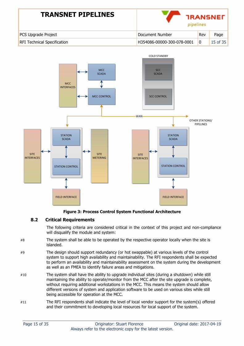
The Process Control System is distributed across 50 sites, over approximately 3800km, linked to a Master Control Centre (MCC). It shall be possible to control each station either locally from
the station, or remotely from the MCC. Each site shall be self-sufficient such that a loss of communication to a station does not prevent the local control of that station.
When control is run locally for a section of the station, control shall be passed to the local
station operator explicitly such that there are no two points of control at a single time.
It is also important that the stations’ software can be individually upgraded (offline) and put
into operation while still maintaining the ability to operate/monitor from the MCC after the site upgrade is complete, without requiring additional workstations in the MCC.
The performance of the SCADA locally at the station and in the MCC is critical for effective operations in a hydraulic pipeline environment, as delays in switching of product can lead to
late product switches and inability to maintain the safe operational status of the pipeline during
an upset event, product losses, contamination and unsafe or unstable pipeline conditions.
Each station’s control system may interface to a local metering system, VSDs, field device,
electrical switchgear, motor control centres, and other local systems.
TRANSNET PIPELINES
PCS Upgrade Project Document Number Rev Page
RFI Technical Specification H354086-00000-300-078-0001 0 15 of 35
Page 15 of 35 Originator: Stuart Florence Original date: 2017-04-19 Always refer to the electronic copy for the latest version.
STATION SCADA
STATION CONTROL
FIELD INTERFACE
MCCSCADA
MCC CONTROL
STATION SCADA
STATION CONTROL
FIELD INTERFACE
SCCSCADA
SCC CONTROL
SITE INTERFACES
SITE INTERFACES
MCC INTERFACES
WAN
OTHER STATIONS/PIPELINES
COLD STANDBY
SITE METERING
Figure 3: Process Control System Functional Architecture
8.2 Critical Requirements
The following criteria are considered critical in the context of this project and non-compliance
will disqualify the module and system:
#8 The system shall be able to be operated by the respective operator locally when the site is
islanded.
#9 The design should support redundancy (or hot swappable) at various levels of the control system to support high availability and maintainability. The RFI respondents shall be expected
to perform an availability and maintainability assessment on the system during the development as well as an FMEA to identify failure areas and mitigations.
#10 The system shall have the ability to upgrade individual sites (during a shutdown) while still maintaining the ability to operate/monitor from the MCC after the site upgrade is complete,
without requiring additional workstations in the MCC. This means the system should allow
different versions of system and application software to be used on various sites while still being accessible for operation at the MCC.
#11 The RFI respondents shall indicate the level of local vendor support for the system(s) offered and their commitment to developing local resources for local support of the system.
TRANSNET PIPELINES
PCS Upgrade Project Document Number Rev Page
RFI Technical Specification H354086-00000-300-078-0001 0 16 of 35
Page 16 of 35 Originator: Stuart Florence Original date: 2017-04-19 Always refer to the electronic copy for the latest version.
#12 The system shall be scalable to support the many pipelines which form part of the TPL network. The system should support up to 50 sites visible from the MCC from a single Operator
Workstation.
#13 The system shall comply with the System Performance requirements specified in Section 8.3.7
of this document.
8.3 Module Requirements
The detailed requirements for the Process Control System are given in the PCS User
Requirements Specification [2].
The following items are required functionality and/or characteristics for the Process Control System:
8.3.1 General
The PCS should be based on open software and communication standards. Any non-
industry standard technology shall be declared. The RFI Respondent(s) should indicate which open standards they support for interfacing to other systems.
The PCS and its components shall have a proven track record in similar petroleum
pipeline and terminal operations. Any design or device which has limited operating experience shall be declared. Prototypes or equipment out-of-date shall not be used.
Commercially available off-the-shelf equipment should be used as far as reasonable.
A cold standby Secondary Process Control System shall be installed. Capability for
Warm/Hot Standby shall be declared.
The Operating System platform should support Unix style systems (e.g. Linux), although
Windows based systems will be considered. This is required to satisfy system vulnerability and maintainability concerns which are to be explicitly addressed in the
response.
Demonstration of security robustness, and virus and operating system update
frequency, with evidence from existing sites shall be provided.
The system should support real-time coordination control (Line Wide Control) of the
pipeline from the MCC. This includes startup\shutdown sequences, pipeline optimisation
and other line wide functions. This may invoke a separate controller dedicated to such a function.
The RFI respondents shall indicate the level of local support for the system(s) offered
and their commitment to developing local resources for local support of the system(s).
8.3.2 Control
The sites are controlled locally and remotely, and as a result a means of transfer of
control (mode of control) is required for device groups of plant operations. The mode of
control transfer shall meet the following:
i. When the MCC is in control of a portion of the plant (device group), the Station HMI
shall be “view only” with no active alarms for those portions.
ii. When the Station has control of the portion of the plant (device group), the MCC shall be “view only” with no active alarms for those portions of plant.
iii. It shall be possible for the MCC to remotely disable control from the Station and vice versa under operations supervisor password, but normally transfer between the 2 sites
will be an operator request and handover type transfer.
The RFI Respondent(s) should indicate how this is achieved for the system.
TRANSNET PIPELINES
PCS Upgrade Project Document Number Rev Page
RFI Technical Specification H354086-00000-300-078-0001 0 17 of 35
Page 17 of 35 Originator: Stuart Florence Original date: 2017-04-19 Always refer to the electronic copy for the latest version.
8.3.3 Alarming
The system should have a comprehensive alarm system with multiple priorities and
support multiple methods of suppression and alarm minimisation.
Alarms shall automatically follow the mode of control to which the subset of plant
operations has been transferred i.e. alarms will only be annunciated in MCC if the subset of plant operations is being controlled from the MCC, and only from the Station if the
subset of plant operations is being controlled locally from the station.
The alarm should only be audible and acknowledgeable for the operator in control of the
portion of plant section.
8.3.4 Interfaces
The system shall support OPC 2.0, OPC UA, Profibus DP, Modbus TCP/485. The RFI
Respondents should indicate all standard interfaces that the system supports.
The Process Control System shall be required to interface to:
Custody Metering System (CMS) at a site level,
Equipment at a site level eg. VSDs, F&G, etc.,
Pipeline Monitoring System (PLMS) at the MCC,
MES/MIS operations systems at the MCC
Transnet Pipelines has an existing installed base of Siemens Simatic S7 S400 PLCs. The
RFI Respondents should indicate whether standard interfaces to these PLCs are available or S7 300 I/O and Profibus networks.
8.3.5 Data Archiving
Short term trending of 3 months shall be available online on the operator interface.
The system shall support archiving of up to 10,000 different variables per site, scanned
at 1000 per sec.
Long term archiving for two years shall be available for all alarms, events, digital and
analog variables. The system should support basic analysis of plant operation and trending.
8.3.6 Development
The PCS engineering system shall support versioning and revision control of the PCS at
all levels.
It should be possible to compare multiple versions of application software for conflict
resolution.
The system shall support local engineering on a station when the station is islanded (i.e.
not connected to the WAN).
The system shall support standard and custom libraries which can be managed and
controlled over widely separated sites.
8.3.7 System Performance
The system is expected to perform over a low bandwidth, high latency environment. The RFI Respondents should provide indicative performance based on past projects in a similar
environment.
Local Performance
A typical control function on the PCS (excluding sensors and actuators) shall have an
availability of 99.98%.
TRANSNET PIPELINES
PCS Upgrade Project Document Number Rev Page
RFI Technical Specification H354086-00000-300-078-0001 0 18 of 35
Page 18 of 35 Originator: Stuart Florence Original date: 2017-04-19 Always refer to the electronic copy for the latest version.
If a single failure can impact multiple functions, the single point of failure should be
mitigated where practical. The RFI Respondent should provide information on redundancy configurations, and how single points of failure can be mitigated.
Loss of WAN connectivity shall not impact the ability of the operator to control the
station locally. Upon WAN recovery, system recovery enabling remote control from the MCC should be an automatic process, with no adverse effect on system performance.
For a graphic with 300 control objects (e.g. valves, motors):
i. time to display an input from the process on the operator interface: 1.5 s;
ii. time for an operator action to be actuated to the process: 1.5 s;
iii. time for a graphic page to display after call-up: 2 s;
iv. time for feedback of a selection (e.g. border on a button): 0.2 s; and
v. time between screen updates: 1 s.
Performance requirements listed above shall include of the communication overhead in
terms of bandwidth and latency constraints identified in Section 7.
MCC over WAN Performance
For a graphic with 300 control objects (e.g. valves, motors):
i. time to display an input from the process on the operator interface: 2 s;
ii. time for an operator action to be actuated to the process: 2 s;
iii. time for a graphic page to display after call-up: 2.5 s;
iv. time for feedback of a selection (e.g. border on a button): 0.2 s; and
v. time between screen updates: 1.5 s.
Performance requirements listed above shall include of the communication overhead in
terms of bandwidth and latency constraints identified in Section 7.
8.3.8 Security
The system shall support system wide security management.
The system shall support a tight cyber-security philosophy. The RFI Respondent to
indicate how typical cyber security provisions are met.
The PCS shall support physical ‘system (hardware& software) lock down’.
8.3.9 Maintenance and Upgrades
The system shall be upgradeable in a staged approach without the necessity of parallel
old and new systems i.e. it shall be possible for stations to be upgraded individually without impacting MCC connectivity or requiring additional Operator Stations. This
means that a single station can be operating on a different version of system/project
software and still be visible at the MCC without requiring separate hardware. Limited site downtime is acceptable for a system upgrade.
Project specific application software shall not require modifications in order to be able to
run under new releases of the system operating software. Any new release of system software shall be backward compatible with files created using the previous software
releases.
Operating system patching should have a minimal impact on operations.
8.3.10 Replay
The PCS should have the capability of replaying process inputs, operator actions, alarms
and events.
The result of the replay shall be visible on standard HMI displays.
TRANSNET PIPELINES
PCS Upgrade Project Document Number Rev Page
RFI Technical Specification H354086-00000-300-078-0001 0 19 of 35
Page 19 of 35 Originator: Stuart Florence Original date: 2017-04-19 Always refer to the electronic copy for the latest version.
The initiation of a replay shall not require significant engineering effort, but be possible
by a trained supervisor.
The replay system should be suitable for incident investigation. The RFI Respondents to
indicate similar systems which have been implemented on petroleum pipelines.
8.3.11 HMI Trainer/Simulation
The PCS shall have the capability of simulating the field inputs and other defined
interface inputs (e.g. MODBUS, OPC).
The simulation interface should be similar to the HMI screens to support ease of
simulation.
The simulation subsystem shall support the loading of scenarios for the field interface.
The trainer system shall provide control simulation of the actual operation of the
Station.
Device and equipment simulation shall be automatic. Hydraulic simulation is not
required.
The trainer system shall run the same software as the station software.
8.3.12 Proof of Concept Workshop
The RFI Respondent(s) shall perform a proof of concept by test or demonstration at the RFI stage which will demonstrate:
1. Performance over a high latency bandwidth limited system (Section 7) – The respondent
shall test performance over a simulated slow network.
2. MCC/Station operation architecture – The architecture of the proposed system should be
presented and discussed.
3. The RFI respondent will be required to demonstrate required performance with 20 sites
visible from the MCC from a single Operator Workstation.
4. The RFI respondent will be required to provide an assessment of the TPL requirements
contained in the PC Software Control Modules Standard (Ref [3]), in particular as regards
engineering effort and system performance.
5. Alarm locality – The mechanism of how alarm locality operates and follows mode of control
should be demonstrated.
6. Mode of control handover – the mechanism of how mode of control is implemented and the
handover should be demonstrated.
7. Critical interface concepts – The OPC interface, Modbus, Profibus interface should be
demonstrated.
8. Method of upgrading the system as per Section 8.2 – A demonstration should be done
showing how the system application and system software should be upgraded and its
impact on operations and maintenance.
9. HMI frameworks – The mechanism for managing alarms, typicals, navigations, trending, et
al should be demonstrated.
10. Reporting – The configuration and execution of the reporting\trending system proposed
should be demonstrated.
TRANSNET PIPELINES
PCS Upgrade Project Document Number Rev Page
RFI Technical Specification H354086-00000-300-078-0001 0 20 of 35
Page 20 of 35 Originator: Stuart Florence Original date: 2017-04-19 Always refer to the electronic copy for the latest version.
8.4 Capability
8.4.1 Operational Data Warehouse
The RFI Respondent(s) should indicate their capability to provide a system which meets the
following needs,
Link to various data sources on a site. The system may store the data or link to the
respective data store. These sources may include electrical metering, control system,
alarm system, PLMS, Custody Metering, condition monitoring, fire and gas, and internet data if required.
Allow reporting of KPIs for operational and maintenance of the pipeline.
The system should be user configurable such that analysis, investigation and reporting
can be performed by operational and maintenance staff. This would allow reports and
investigations supporting:
Preventative maintenance
Cost optimisations
Equipment performance
Incident investigations
Trip avoidance
Setpoint analysis
Alarm Analysis
The system should support functions such as:
Cross correlations across variables
Meta Tagging data and events
Basic data analytics (clustering, regression, time series analysis, pattern recognition,
spatial)
Utilise geospatial information as a means of visualising data
Signal processing (filtering/frequency/time)
Strong visualisation tools
The system should support the following type of data:
Geospatial data
Time series data
Transactional data
Event/Alarm data
Text and complex data
8.4.2 Terminal Management
The RFI Respondent(s) should indicate their capability to provide a system which meets the
following needs:
Interface to Tank Gauging and other metering systems to track product into and out of
a terminal.
Support management of road and rail loading including management of fuel additives.
Support inventory reconciliation.
Support product quality tracking and management, including interface to lab
instrumentation.
Support reporting of inventory and operations.
TRANSNET PIPELINES
PCS Upgrade Project Document Number Rev Page
RFI Technical Specification H354086-00000-300-078-0001 0 21 of 35
Page 21 of 35 Originator: Stuart Florence Original date: 2017-04-19 Always refer to the electronic copy for the latest version.
Support integration into a SCADA system and other aspects of the Operation Systems
platform.
TRANSNET PIPELINES
PCS Upgrade Project Document Number Rev Page
RFI Technical Specification H354086-00000-300-078-0001 0 22 of 35
Page 22 of 35 Originator: Stuart Florence Original date: 2017-04-19 Always refer to the electronic copy for the latest version.
9. System Module 2: Custody Metering
9.1 Overview
The Custody Metering module consists a metering system with flow computers to support the Fiscal/Custody Measurement of petroleum multi-products entering or leaving the Transnet
Pipeline infrastructure.
The Metering System is to be a stand-alone, automated, electronic metering system used to measure the volume transfer of product at these sites and will comprise of the following five
main components:
Metering System Database (MDS), used for collating and storing metering data. It is
also used to interface to the SCADA and ERP (SAP).
Metering System HMI, used for operator interface.
Metering System Flow Computers, used to measure product transfer to API Product
Measurement, OIML and SA Trade Metrology Standards. Flow Computers interface directly to field instrumentation and large volume provers.
Metering Instrumentation, including turbine flow meters, pressure, temperature and
density measurements.
Meter Proving facilities that should be monitored and controlled by the CMS.
The CMS shall have the ability to generate metering reports for deliveries, proving and
other technical metering reports.
The CMS shall interface to existing metering process equipment installed on TPL sites,
and specifically into turbine flow meters and large volume, bi-directional pipe provers.
Metering is only required to be operational from the respective stations themselves.
9.2 Metering Process Equipment
Metering manifolds installed on TPL sites comprise of de-aerators, strainers, turbine meters,
flow conditioners where required, proving systems, consignee/nor valves and metering
instrumentation (temperature, pressure and density measurements). On intake sites, product passes from the consignor valve to the meter and then to the prover; whilst on delivery sites,
product passes through the prover followed by the meter and lastly the consignee valve.
Backpressure is maintained on the turbine flow meters by means of pressure-sustaining valves
where necessary. Temperature and pressure of the product at the meter is measured and the
values fed back to the Flow Computer for volume calculation purposes. Density is measured and entered manually by the operator.
Meters are calibrated regularly using permanent on-site large volume pipe prover facilities, comprising of bi-directional provers with flow direction controlled by means of four-way valves.
Six sphere detector switches are installed on the prover, two detector switches used to detect the sphere in its home and away positions, with the other four detector switches used as base
volume switches. The four-way valve cavity is fitted with a differential pressure switch to
indicate if the valve is leaking or not. Temperature and pressure of the product at the prover is measured and the values fed back to the flow computer for metering compensation calculation.
9.3 Scope of RFI
The scope of supply for this RFI is the custody metering system database and HMI. The flow
computers may be in the scope depending on the RFI Respondents ability to interface to an
Emerson S600+ flow computer. The field instrumentation is not in the scope of this RFI.
TRANSNET PIPELINES
PCS Upgrade Project Document Number Rev Page
RFI Technical Specification H354086-00000-300-078-0001 0 23 of 35
Page 23 of 35 Originator: Stuart Florence Original date: 2017-04-19 Always refer to the electronic copy for the latest version.
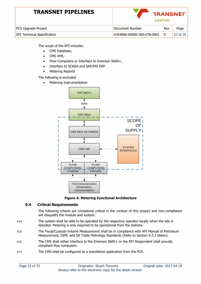
The scope of the RFI includes:
CMS Database,
CMS HMI,
Flow Computers or Interface to Emerson S600+,
Interface to SCADA and SAP/MII ERP
Metering Reports
The following is excluded
Metering Instrumentation
WAN
SAP (MCC)
SAP (Site)
CMS MDS DATABASE
CMS HMI
FLOW
COMPUTERS
STREAM
FLOW
COMPUTERS
PROVER
Field Instrumentation
(Flowmeters,
Instrumentation)
SYSTEM
INTERFACES
SCOPE
OF
SUPPLY
Figure 4: Metering Functional Architecture
9.4 Critical Requirements
The following criteria are considered critical in the context of this project and non-compliance
will disqualify the module and system:
#14 The system shall be able to be operated by the respective operator locally when the site is islanded. Metering is only required to be operational from the stations.
#15 The Fiscal/Custody Volume Measurement shall be in compliance with API Manual of Petroleum Measurement, OIML and SA Trade Metrology Standards (Refer to Section 9.5.2 below).
#16 The CMS shall either interface to the Emerson S600+ or the RFI Respondent shall provide
compliant flow computers.
#17 The CMS shall be configured as a standalone application from the PCS.
TRANSNET PIPELINES
PCS Upgrade Project Document Number Rev Page
RFI Technical Specification H354086-00000-300-078-0001 0 24 of 35
Page 24 of 35 Originator: Stuart Florence Original date: 2017-04-19 Always refer to the electronic copy for the latest version.
#18 The RFI respondents shall indicate the level of local support for the system(s) offered and their commitment to developing local resources for local support of the system.
#19 The system shall comply with the System Performance requirements specified in Section 9.5.8 of this document.
9.5 Module Requirements
The detailed requirements for the Custody Metering System are given in the CMS User Requirements Specification [1].
The following items are required functionality and/or characteristics for the Custody Metering System:
9.5.1 General
The CMS should be based on open standards. Any non-industry standard technology
shall be declared in the response.
The CMS should preferably be a commercially off-the-shelf application, requiring only
configuration.
The CMS should be able to meet the functional requirements using the standard
manufacturers system. Any requirements which impose high levels of customisation
shall be declared in the response.
The CMS and its components shall have a proven track record in a similar pipeline and
terminal operation. Any design or device which has limited operating experience shall be
declared. Prototypes or equipment out-of-date shall not be used.
The CMS shall support a HMI for the operator to:
manage the reconciliation of deliveries
trouble shoot problems
respond to alarms
initiate and monitor proving status and other metering operations, including the ability
to control 4-way valve when proving manually
configure and manage flow computers
monitor deliveries, with associated volumes, flows and other variables.
generate metering reports
The RFI respondents shall indicate the level of local support for the system(s) offered
and their commitment to developing local resources for local support of the system(s).
9.5.2 Certification and Approvals
The CMS shall support Fiscal/Custody Volume Measurement in accordance with API
Manual of Petroleum Measurement Standards (Ref [6]).
All components of the CMS shall be certified for use in fiscal/custody transfer
applications by OIML [5] (i.e. OIML R117 Certificates of Conformity will need to be
issued for all components of the system).
The CMS should be certified by the SA Authorities body for use in accordance with the
SA Trade Metrology Act.
The RFI Respondent(s) should indicate how these requirements are achieved for the
system.
9.5.3 Alarming
The system shall support an alarm and event system which can interface to a SCADA
system. Batch alarms shall be made available on a SCADA system.
TRANSNET PIPELINES
PCS Upgrade Project Document Number Rev Page
RFI Technical Specification H354086-00000-300-078-0001 0 25 of 35
Page 25 of 35 Originator: Stuart Florence Original date: 2017-04-19 Always refer to the electronic copy for the latest version.
The system shall maintain events for event investigation and diagnostics.
9.5.4 Interfaces
The Respondent(s) CMS shall either:
Interface to the Emerson S600+ using Modbus or similar technology,
OR:
Include certified (API/OIML) flow computers suitable for custody transfer and use with large volume provers and turbine meters as installed at the Fynnlands and Coalbrook
sites.
The CMS shall interface to a minimum of sixteen (16) Flow Computers (stream and
prover) and shall support a minimum of eight (8) simultaneous product volume transfers
and 8 provers.
The CMS shall interface to SAP/MII via XML B2MML to return docket information.
The CMS shall interface to the SCADA through OPC 2.0/UA with basic information such
as flow rates, volumes and delivery status.
Values for Flowrates, Volumes, Temperature and Pressure shall be interfaced to the
SCADA from the flow computer via the CMS.
The CMS interface to flow computers shall enable reconfiguration to accommodate
future changes.
9.5.5 Archiving
Operator actions shall be captured; time stamped and logged in the operator log.
The CMS shall provide a complete historical (archiving) subsystem providing the ability
to capture and analyse historical data (CMS Database).
The HMI shall provide an integral reporting subsystem to be used to print any variable,
event or history of both current and archived data.
The system store historical data for years for reporting (e.g. 2 year archiving of meter
factor trends)
9.5.6 Reporting
The HMI shall provide an integral reporting subsystem to be used to print any variable,
event or history of both current and archived data.
Reports shall be easily configurable and customisable and shall provide the capability to
define reports for visualisation on the Metering HMI and for printing.
Reports shall be activated in any of the following manners: upon demand, or scheduled,
or upon event occurrence.
9.5.7 Development
The CMS should preferably use a standard library; if not possible then only standard
CMS components shall be used in the building of the custom library.
The CMS engineering system shall support versioning and revision control of the PCS at
all levels.
It should be possible to compare multiple versions of software for conflict resolution.
The system shall support local engineering on a station.
9.5.8 Performance
Failures of instrumentation, equipment, I/O and other detectable failures shall be visible
to the operator and be alarmed.
TRANSNET PIPELINES
PCS Upgrade Project Document Number Rev Page
RFI Technical Specification H354086-00000-300-078-0001 0 26 of 35
Page 26 of 35 Originator: Stuart Florence Original date: 2017-04-19 Always refer to the electronic copy for the latest version.
Failure of an operator station shall not prevent other operator stations from operating or
introduce unwanted control actions.
Failure of a flow computer shall not affect any of the other flow computers at a site.
Failure of the CMS system and associated networks shall not affect Flow Computer
operation.
A typical control function on the CMS (excluding sensors and actuators) shall have an
availability of 99.98%.
Loss of WAN connectivity shall not impact the ability of the operator to meter product
volume movement from the CMS at the station locally.
CMS shall meet the following performance criteria,
Maximum 60 seconds response time when initiating a report print from the Flow Computer to printing the report from the CMS.
Maximum 1 second response time for real-time data from the Flow Computer to be
displayed on the CMS HMI graphics.
Maximum 3 seconds for non-real time data and 60 seconds for configuration data to be
sent from the CMS to the FC and back, including Screen Update response times within the CMS System.
Maximum two minutes data processing time for data transfer between CMS and SAP.
9.5.9 Security
The CMS shall support system wide security management.
The CMS shall support a tight cyber-security philosophy. The RFI Respondent to indicate
how typical cyber security provisions are met.
9.5.10 Maintenance
The system should be upgradeable in a staged approach without the necessity of
parallel systems. Limited downtime is acceptable for a system upgrade.
Software design shall be such that future revisions or updates of the system operating
software will not affect the successful operation of the system.
Project specific application software shall not require modifications in order to be able to
run under new releases of the system operating software. Any new release of system
software shall be backward compatible with files created using the previous software releases
9.5.11 Proof of Concept Workshop
The Respondent(s) shall perform a proof of concept by test or demonstration at the RFI stage
which will demonstrate:
1. If the architecture is dependent on WAN infrastructure: performance over a high latency
bandwidth limited system (Section 7) – The respondent should show indicative
performance over simulated slow network.
2. Critical interface concepts – The interfacing to a Floboss S600+ (or the respondents flow
computer), as well as the typical SCADA interface should be demonstrated, including
protocol mapping and reporting.
3. Method of upgrading the system as per Section 9.4 - 8.2 – A demonstration should be done
showing how the system application and system software should be upgraded and its
impact on operations and maintenance.
TRANSNET PIPELINES
PCS Upgrade Project Document Number Rev Page
RFI Technical Specification H354086-00000-300-078-0001 0 27 of 35
Page 27 of 35 Originator: Stuart Florence Original date: 2017-04-19 Always refer to the electronic copy for the latest version.
4. HMI and operational frameworks – The mechanism for managing alarms, typicals,
navigations, trending, et al should be demonstrated.
5. Reporting - The standard reporting as well as custom report configuration and execution
should be demonstrated.
6. Demonstration of metering and proving - The mechanism of executing a metering run and
proving run should be demonstrated.
9.6 Capability
9.6.1 Metering Trainer
The RFI Respondents should indicate their solution to a metering trainer, including:
The Metering Trainer should simulate the actual operation of the Metering System
The Metering Trainer should is capable of simulating the field inputs and other defined
interface inputs (e.g. MODBUS, OPC).
The Metering Trainer should run the same software as the CMS software.
9.6.2 Flow Computers
The RFI Respondents should indicate their solution to flow computers based on the following
requirements:
Flow Computers shall support Fiscal/Custody Volume Measurement in accordance with
OIML, SA Trade Metrology, API Manual of Petroleum Measurement Standards as well as
interfacing to large volume provers.
Electronic measuring systems (Flow Computers) shall be designed and manufactured to
Accuracy Class 0.3 (OIML R117 Section 2.4 Table 1 [5]), ensuring that their errors do not exceed the maximum permissible errors as defined in OIML R117 Section 2.5 under
rated operational conditions.
Flow Computers shall be standalone units, fitted with front panel keypads and displays
to enable local operator control and logging functions as well as provide status of all
inputs and configuration settings.
Transnet Pipelines currently has a large installed base of Emerson Floboss S600 and
S600+ Flow Computers installed. Supply of an alternative make of flow computer shall
be considered, provided compliance to the CMS User Requirements Specification [1] is
declared and all requirements are separately validated.
One Flow Computer should be supplied per meter stream and used to provide flow
meter pulse integrity checks as well as both metering and proving functions.
The Flow computer shall have the ability to interface to 10 or more consignees.
The flow computer components shall be modular for ease of replacement when cards
are faulty.
The FC are to operate independently to each other and independently of the CMS and
robustly handle failure of field I/O’s.
TRANSNET PIPELINES
PCS Upgrade Project Document Number Rev Page
RFI Technical Specification H354086-00000-300-078-0001 0 28 of 35
Page 28 of 35 Originator: Stuart Florence Original date: 2017-04-19 Always refer to the electronic copy for the latest version.
10. System Module 3: PLMS
10.1 Overview
The PLMS modules consist of Leak Detection (LDS), Batch Tracking (BTS), Pig and Sphere Tracking (PTS) and Pressure Dynamic Tracking (PDTS), required for the monitoring of Transnet
Multi-product Pipeline infrastructure. Note that only a Leak Detection System required for
operation on the Crude Oil Pipeline. The RFI Respondent(s) should indicate the functionality of the other modules under the capability section with a view to future use.
10.2 Critical Requirements
The following criteria are considered critical in the context of this project and non-compliance will disqualify the module and system:
#20 The system shall operate in shut-in, transient and steady state conditions.
#21 The system shall be able to detect a leak of 10% of flowrate size on a pipeline of flow segment
size 100km within 10 minutes, with a leak location accuracy of 5%. The RFI Respondent(s) are
to indicate what the requirements are on process instrumentation accuracy to achieve this. The RFI Respondent(s) are also to indicate actual detection times for a 1%,5%, 10% and 30% leak.
#22 The LDS shall support an open technology (e.g. OPC UA) to interface alarms and signals through to and from the SCADA system.
#23 The system shall minimize the reliance on flow meters. Failure of a single flow meter should not
prevent LDS operation. The RFI Respondent(s) are invited to offer alternative technologies, measurements or instruments which may be used.
10.3 Module Requirements
The following items are required functionality for the Leak Detection System:
10.3.1 General
The system shall operate in shut-in, transient and steady state conditions.
The system shall comply to API1155, API1130 and API1149 as applicable to the
technology of the LDS.
The system shall minimize the reliance on flow meters. Failure of a single flow meter
should not prevent LDS operation. The RFI Respondent(s) are invited to offer alternative
technologies, measurements or instruments which may be used.
The RFI Respondents should indicate if they offer local or remote (relative to South
Africa) support of the LDS system to assess the system state, tuning of the system and analysis of potential leaks.
The system shall support rupture detection. The RFI Respondent(s) to indicate the
typical performance achieved.
10.3.2 Alarming
The system shall support an alarm and event system which can interface to a SCADA
system. All alarms shall be made available on a SCADA system.
The system shall maintain events for event investigation and diagnostics.
10.3.3 Interfaces
The LDS shall support an open technology (e.g. OPC UA) to interface alarms and signals
through to and from the SCADA system.
TRANSNET PIPELINES
PCS Upgrade Project Document Number Rev Page
RFI Technical Specification H354086-00000-300-078-0001 0 29 of 35
Page 29 of 35 Originator: Stuart Florence Original date: 2017-04-19 Always refer to the electronic copy for the latest version.
The LDS shall support an open technology to get field data either from the SCADA/PLC
or from field instruments directly.
10.3.4 Archiving
The system shall be designed to retain 2 years of data relating to leak alarms and leak
analysis.
10.3.5 Development
The LDS system shall support versioning and revision control of the LDS at all levels.
It shall be possible to see the current custom version of software which is in operation.
10.3.6 Performance
The system shall be able to detect a leak of 1% of flowrate size on a pipeline of flow
segment size 100km. The RFI Respondent(s) are to indicate what the requirements are
on process instrumentation accuracy to achieve this. The RFI Respondent(s) are also to
indicate typical detection times for a 1%,5%, 10% and 30% leak.
The system should support leak location to 3% of segment length. The RFI
Respondent(s) are to indicate what the requirements are on process instrumentation
accuracy to achieve this.
10.3.7 Security
The system shall support system wide security management.
The system shall support a tight cyber-security philosophy. The RFI Respondent to
indicate how typical cyber security provisions are met.
10.3.8 Maintenance
Project specific application software should not require modifications in order to be able
to run under new releases of the system operating software. Any new release of system software shall be backward compatible with files created using the previous software
releases, or a migration path should be allowed for.
10.3.9 Proof of Concept
The Respondent(s) shall indicate their willingness to perform a proof of concept at the RFI stage
which will demonstrate:
1. Performance over a high latency bandwidth limited system (Section 7) – The respondent
should show indicative performance over simulated slow network.
2. Critical interface concepts – The OPC interface to the SCADA and it requirements should be
demonstrated.
3. Demonstration of HMI frameworks – The mechanism for managing alarms, typicals,
navigations, trending, et al should be demonstrated
4. Reporting – The configuration and execution of the reporting\trending system proposed
should be demonstrated.
10.4 Capabilities
RFI Respondents should indicate the level of functionality for the identified systems:
TRANSNET PIPELINES
PCS Upgrade Project Document Number Rev Page
RFI Technical Specification H354086-00000-300-078-0001 0 30 of 35
Page 30 of 35 Originator: Stuart Florence Original date: 2017-04-19 Always refer to the electronic copy for the latest version.
10.4.1 Pressure Dynamic Tracking System
The RFI Respondents should indicate if they are capable of delivering a Pressure
Dynamic Tracking System which models the hydraulic profile of a pipeline in real-time.
The calculated values should be visible on the SCADA system. The typical performance, requirements on instrumentation and other relevant system details should be provided.
10.4.2 Batch Tracking System
The RFI Respondents should indicate if they are capable of delivering a Batch Tracking
System which models the location of batches in a pipeline in real-time. The typical performance, requirements on instrumentation and other relevant system details should
be provided.
10.4.3 Pig Tracking System
The RFI Respondents should indicate if they are capable of delivering a Pig Tracking
System which models the location of pigs and spheres in a pipeline in real-time. The
typical performance, requirements on instrumentation and other relevant system details
should be provided.
TRANSNET PIPELINES
PCS Upgrade Project Document Number Rev Page
RFI Technical Specification H354086-00000-300-078-0001 0 31 of 35
Page 31 of 35 Originator: Stuart Florence Original date: 2017-04-19 Always refer to the electronic copy for the latest version.
11. Project Wide/Common Module
11.1 Overview
All RFI respondents are required to address the project wide (common) requirements and capabilities listed below.
11.2 Common Requirements
Each RFI Respondent is required to address their level of compliance to the requirements listed below:
11.2.1 Regulatory Compliance
The execution of the project, including system hardware, software and contracted
services shall comply with applicable South African Regulations.
11.2.2 General Quality
The execution of the project including all hardware and software shall be subject to
formal quality management plans and procedures, approved by the Employer.
The RFI Respondents shall be ISO9001 certified.
The RFI Respondents’ ISO9001 certification shall cover the full scope of products and
services relevant to this RFI.
11.2.3 Software Lifecycle Quality
All configuration and development shall be done according to an approved software
lifecycle and quality plan according to the lifecycle requirements laid out by the
Employer.
All software shall be:
formally managed by a change control process, including formal configuration
management,
tested according to documented software test plans and procedures,
configuration managed and version controlled.
The software lifecycle plan shall be based on a recognised international lifecycle
standard such as IEEE 12207.
The development standards (for both standard modules and site software) for the
project shall be documented and enforced.
All interfaces shall be subject to formal validation.
All project software shall be subject to a formal defect correction process.
Control simulation shall be implemented during the FAT process as a means to fully test
the functional scope.
RFI Respondents are to provide traceable references to comparable projects performed
in a formal, quality controlled environment.
11.2.4 Documentation
RFI Respondents will be required to adhere to Employer’s standards with respect to
documentation format and templates.

TRANSNET PIPELINES
PCS Upgrade Project Document Number Rev Page
RFI Technical Specification H354086-00000-300-078-0001 0 32 of 35
Page 32 of 35 Originator: Stuart Florence Original date: 2017-04-19 Always refer to the electronic copy for the latest version.
A full compliance assessment shall be retained by the RFI Respondent(s) for the
development and rollout of software against the Employer’s requirements documentation and the RFI Respondents requirements documentation.
All project documentation shall be as-built.
A full suite of project documentation shall be developed including:
Functional design specifications
Hardware detail design documentation
System and Software design documentation
Software test documentation
Operations and Maintenance documentation
Configuration and setup documentation
System, Operator and Technician/Engineer Training Manuals
Project Records e.g. Compliance, Manufacturing, Test, Quality
11.2.5 Support/Lifecycle
The system shall be designed for a Service Life of 15 years before the product is End of
Life.
The system shall be designed such that system update frequency and version support
exceeds 5 years.
The RFI Respondent shall identify the proposed location for software development, and
the depth of resourcing and competence.
The Respondent(s) shall indicate the level of support offer for operations and
maintenance. The response should indicate where the support would be delivered from.
First and Second line support should be localised (South Africa). The RFI Respondent(s)
to indicate their willingness to develop local (South African) expertise to support the
systems, or demonstrate the such expertise already exists locally.
The RFI Respondent(s) shall indicate how the custom developments for this project will
be integrated into mainline product development to ensure future support.
The RFI Respondent(s) should demonstrate what provisions exists for integration of
future operational needs and requirements from the Employer to inform mainstream
system development.
11.2.6 Project Experience
The RFI Respondent(s) shall indicate the level of their experience with projects of
similar technical scope and size. This shall include brown field and multi-product pipeline system upgrades.
The RFI Respondent(s) shall indicate where the proposed system(s) have been used in
a similar pipeline/terminals operation. Traceable references should be provided. The
maturity of the product should also be detailed.
The RFI Respondents shall indicate the size of user base for the proposed system(s) in a
similar pipeline/terminal environment.
The RFI Respondents should indicate lessons learnt associated with the development,
installation, operation and maintenance of the proposed system(s).
TRANSNET PIPELINES
PCS Upgrade Project Document Number Rev Page
RFI Technical Specification H354086-00000-300-078-0001 0 33 of 35
Page 33 of 35 Originator: Stuart Florence Original date: 2017-04-19 Always refer to the electronic copy for the latest version.
11.2.7 Project Execution
The RFI Respondent(s) shall indicate the level of their experience in developing,
executing and integrating projects of similar technical scope and size. This shall include
brown field and multi-product pipeline system upgrades.
The RFI Respondent(s) shall indicate the level of experience in integrating third party
systems and management of the interfaces.
The RFI Respondent(s) shall indicate the level of experience in developing software
according to a formal quality process as detailed in Section 11.2.3.
The RFI Respondent(s) should indicate how a project of this type would be executed.
The RFI Respondent(s) should provide a proposed organogram for this project, listing
local and/or international organisations if applicable; and including roles, responsibilities,
and the location of system and software FAT testing.
11.2.8 Commissioning and Support
The system shall be commissioned and formally validated against the performance
specification.
The RFI Respondents shall indicate similar projects where this process has been
followed.
The Respondent(s) shall indicate what levels of support are available for the system(s),
both locally and internationally.
The Respondent(s) shall indicate their ability to assist in site readiness assessments and
detailed shutdown planning.
11.2.9 Ops Readiness Training
The RFI Respondents shall indicate their ability to support operational readiness
processes including,
Training of operations staff
Development of procedures for operation of the system,
11.2.10 Maintenance Training
The RFI Respondents shall indicate their ability to support maintenance readiness
including,
Training of maintenance staff
Development of procedures for maintenance and upgrades of the system.
11.2.11 System Architecture
The RFI Respondents should include a high-level system/network architecture that
demonstrates the ability to meet the requirements of this RFI.
The RFI Respondent should include typical system architectures which have been used
on similar projects.
11.2.12 Localisation
The RFI Respondents shall detail their existing local South African technical capability,
including actions which are in the process, or which would be required to establish a centre of technical competence in South Africa.
TRANSNET PIPELINES
PCS Upgrade Project Document Number Rev Page
RFI Technical Specification H354086-00000-300-078-0001 0 34 of 35
Page 34 of 35 Originator: Stuart Florence Original date: 2017-04-19 Always refer to the electronic copy for the latest version.
11.3 Common Capabilities
The following capabilities are optional for each RFI Respondent to address:
11.3.1 E&I Design
The RFI Respondent(s) to indicate their capability to either perform in-house or contract
directly:
Electrical and Instrumentation panel design,
Loop drawings and terminal schedules,
IO Schedules,
Loop certifications (IS).
11.3.2 E&I Installation
The RFI Respondent(s) to indicate their capability to either perform in-house or contract
directly:
Electrical and Instrumentation installation,
Profibus, network, fibre optic and other cable installation,
Cable installation and termination,
Issuing of Certificates of Compliance (CoCs),
Installation and Safety management.
11.3.3 Panel Manufacture and Hardware Integration
The RFI Respondent(s) to indicate their capability to either perform in-house or contract directly:
Design and build electrical and instrumentation panels according to an Employer’s
standard,
Design and build server panels according to an Employer’s standard,
Factory acceptance test and provide full quality control on the panel manufacture.
Perform system hardware integration.
TRANSNET PIPELINES
PCS Upgrade Project Document Number Rev Page
RFI Technical Specification H354086-00000-300-078-0001 0 35 of 35
Page 35 of 35 Originator: Stuart Florence Original date: 2017-04-19 Always refer to the electronic copy for the latest version.
12. Document Lifecycle Management
12.1 Revision History
The owner of this document is responsible for the revision and control of the document, including updating of the table below, which contains the history of the document with details of each revision.
Date Previous
Rev No.
New
Rev No.
Details of Revision
2017-04-19 -- A Commented First Draft for discussion forum
2017-05-17 B C Updated at Review Workshop at TPL 2017-05-17
2017-05-18 C 0 Issued for RFI
This table summarises what has been changed in the document so that it is easy to keep track
of the effected changes.
12.2 Comments Resolution
Date Section Comment Resolution
This table lists comments and the basis of resolution to keep track of decision outcomes and reasoning.


![TRANSNET PORT TERMINALS Notices... · TRANSNET PORT TERMINALS An Operating Division of TRANSNET SOC LTD [Hereinafter referred to as Transnet] Registration Number 1990/000900/30 REQUEST](https://img.pdfslide.net/doc/110x75/600560c52af56b6cdb7b80d6/transnet-port-notices-transnet-port-terminals-an-operating-division-of-transnet.jpg)