Embed Size (px)
Citation preview
www.ijcrt.org © 2020 IJCRT | Volume 8, Issue 4 April 2020 | ISSN: 2320-2882
IJCRT2004097 International Journal of Creative Research Thoughts (IJCRT) www.ijcrt.org 772
TRANSPARENT INSULATION MATERIALS
DEVICES FOR SUSTAINABLE DEVELOPMENT
AND ENERGY AUDIT IN BUILDINGS
Pawan Kumar Sharma, Kriti Galav*and Chandra Shekhar
Department of Mathematics, Bareilly College, Bareilly 243005,India; *IMT Nagpur 440035, India
Abstract: Sustainable Development in a building is related to focus on low cost and low energy architecture.The site
of work is the key point for investigation. In hilly stations, the buildings are constructed by various types of soil and
rock formations.Varying slope characteristics in development on improper selection of sites often causes landslides,
loss of life and damages of properties. Hill slope less than 300 is stable gradient corresponds to safe angle of repose
of slope forming materials. Computational results for honeycomb cell depth in the range of 2 to 16 cm show that the
cell width range of 7 mm to 19 mm is sufficient to suppress the convection for the angle of inclination of 100 ,400 &
700 and T in the range of 200C to 1200C which is the range of interest in solar thermal applications. Simultaneously
experimental results in fabrication of noryl air heater are capable of providing hot air of temperature difference [150
C-300 C] on a moderate sunny day. Therefore it is a suitable air heater for producing hot air of space heating and
agricultural drying applications. Innovative applications of TIM Devics for sustainability and heat tranfer analysis
corresponding to New Delhi and Leh in India and Boulder in USA for TIM device of depth 5 cm to 10 cm and aspect
ratio of 10-20 considerably enhances the heat flux entering the living space and increases the indoor temperature to
comfortable conditions in cold climates.Therefore an appropriate engineering design of building with TIM insulation
would involve tradeoff between several of above-mentioned factors.
Key Words: Sustainable Development in Buildings, Site of work, Modelling of Noryl Air Heater, Transparent
Insulation Material Technology and Simulation.
Introduction: Sustainable Development in buildings is related with durability, aesthetically pleasant and economic
environment. With special emphasis on passive solar heating and cooling, we can achieve contemporary materials
and devices for the control of air, water and vapor flow, rain penetration, control of light, solar radiation, noise and
fire to provide strength and rigidity. In old days, Greek philosopher Aristotle (384-322 B.C.) advised that house
should have large window on walls facing south and as small as possible window on the north side, with horizontal
www.ijcrt.org © 2020 IJCRT | Volume 8, Issue 4 April 2020 | ISSN: 2320-2882
IJCRT2004097 International Journal of Creative Research Thoughts (IJCRT) www.ijcrt.org 773
shading device above the south facing window to allow the winter sun to shine indoors and cut the direct radiation
entering the room in summer season. Socrates (Circa 400 B.C.) describe techniques for passive heating of building
by providing large fenestration with an horizontal louvre on the south side wall and little fenestration on the north
side wall. During Mohenjo-Daro civilizations in India the same principles for heating and cooling the buildings by
the natural energy sources were used. Ancient Iranian architecture used the concepts like clustering of buildings, use
of thick walls, tree and shrub plantations, rooms basement, wind tower, evaporative cooling etc. for providing cooling
of buildings in summer. Passive solar techniques are used in the construction of dwellings in Chacko Canyon and
Mesa Verde by American Indian as long as AD 1100. The old Indian forts, domes and historical buildings are good
examples of ancient Indian architecture where several concepts like flow of water near the buildings, water fountain,
use of thick walls made of stone, mud, limestone, etc, high ceiling, overhangs, low fenestration area on south and
west side, planting trees, tower in the center of the building, clustering of houses, etc. are used for keeping the
building warm in winter and cool in summer. The early work on sustainable development of buildings was not based
on scientific experiments but on common sense and experience; their thermal performances were far from
satisfactory. Simultaneously natural disasters strikes countries, both developed and developing causes enormous
destruction and creating human sufferings and producing negative impacts on natural economies. To maintain socio-
economic sustainable development, it is necessary to rescue reliable supply of electricity and energy to the different
sectors of economy. As a means of solar energy audit the computational results shows that daily solar energy
collected over 340 square meters of area is equivalent to one barel of the oil, whereas One barel of the oil is
equivalent of 6109 MJ of Energy. The Global average solar energy estimated is about 200 W/m2 or 17 MJ/day.
Development agencies and foundations can accelerate universal energy access by directing funds toward sustainable
market building that directly engages the energy impoverished in creating their own energy. Developed countries
have the facilities to reach the above target; while developing countries like India faces many difficulties in meeting
their energy demand. The expected economic development will considerably boost energy consumption and more
particularly demand for electricity requiring new generating capacity and infrastructures. The installed capacity of
India at the end of march 2004 was about 1,11,400 MW.The ministry of Power envisages “Power for all” by 2019,
which includes electrification of all villages up to the end of april 2018 and PM Modi’s Ujjwala helps LPG coverage
expand to 90% households up to the beginning of 2019 which aims to more than double existing power generation by
a considerable100,000 MW by 2013. Under the Jawaharlal Nehru National Solar Mission, a target of 1100 MW grid
connected solar power was envisaged. A capacity of 500 MW has been enmarked after march 2013 for solar thermal
power plants and 10 such plants were selected under different schemes with different completion schedules for which
a better governance regime is required to ensure cooperation and compliance. Hence a large area solar collector are
essentially needed for solar energy utilization. The conventional solar energy collector are metal like galvanized iron
copper etc. These materials are energy intensive. It takes about 5 years for them to collect solar energy equal to that
used in their production. The plastics are therefore being investigated as an alternative for metallic collectors for
www.ijcrt.org © 2020 IJCRT | Volume 8, Issue 4 April 2020 | ISSN: 2320-2882
IJCRT2004097 International Journal of Creative Research Thoughts (IJCRT) www.ijcrt.org 774
example (Blaga, 1980). Computational investigation shows that some of the plastic have very suitable property for
glazing in collectors as compared to glass.
Honeycomb Design for convection suppression in inclined Plane:Hollands first presented the theoretical
performance characteristics for a honeycomb device. Subsequently it was the subject of several theoretical and
experimental investigations related to their convective, radiative and solar transmittance characteristics.Hollands
(1979) considered the base flow and recommended the engineering design of honeycomb with Nusselt number of 1.2.
The minimum aspect ratio A that is required just to suppress the convection is given by
4/1
2420)(
RaFA (1)
where 00)sin56.652.11/(1 9030,)60(cos45.4)( F (2)
And the value of Ra used here is defined by equation
2341
21 )100()21(2737 pLTRa
(3)
Where TcThTTcThKinTmTm ,2/)()(,/1001 , and p is the atmospheric pressure for mean temperature, 280K
Tm 500K.
By analytical observations, we see that the above expression is also valid for = 0, if F () is taken as 1.072
and the linear interpolation of values for the range 00 to 300 is also permitted. For air, at atmospheric pressure and
moderate temperature (280 K Tm 370 K) the minimum cell width that is required to just suppress the convection
is
𝑑 =(100𝐿)1/4
100𝑐(𝛽)(1+2𝛽1)1/2𝛽1(𝛥𝑇)1/4𝑚𝑡𝑠 =
(100𝐿)1/4
𝑐(𝛽)(1+2𝛽1)1/2𝛽1(𝛥𝑇)1/4𝑐𝑚 (4))
Where L is in m, Tm
1001 is in K-1, T is in K. The function c ( ) is given by
0000 300,sin25.01.19030)(03.1)( forforFc (5)
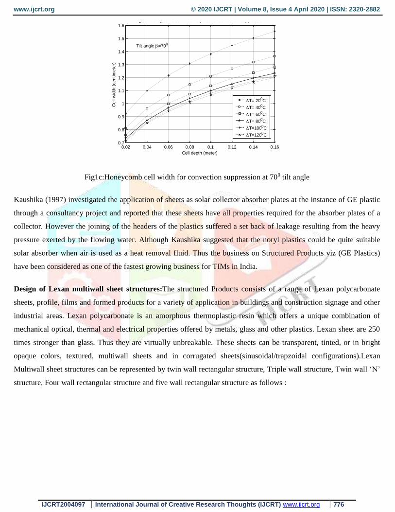
The computational results for the minimum cell width required to suppress the convection for the angle of inclination
of 100 ,400 & 700 based on the above correlations for honeycomb cell depth in the range of 2 to 16 cm and T in the
range of 200C to 1200C which is the range of interest in solar thermal applications are shown in Fig. 1a, 1b &1c. It is
found that cell width range of 7 mm to 19 mm is sufficient to suppress the convection.

www.ijcrt.org © 2020 IJCRT | Volume 8, Issue 4 April 2020 | ISSN: 2320-2882
IJCRT2004097 International Journal of Creative Research Thoughts (IJCRT) www.ijcrt.org 775
Fig1a:Honeycomb cell width for convection suppression at 100 tilt angle
Fig1b:Honeycomb cell width for convection suppression at 400 tilt angle
0.02 0.04 0.06 0.08 0.1 0.12 0.14 0.160.8
1
1.2
1.4
1.6
1.8
2
Cell depth (meter)
Cell w
idth
(centim
ete
r)
Fig 2a: Honeycomb cell width required for convection suppression
Tilt angle =100
T= 200C
T= 400C
T= 600C
T= 800C
T=1000C
T=1200C
0.02 0.04 0.06 0.08 0.1 0.12 0.14 0.160.7
0.8
0.9
1
1.1
1.2
1.3
1.4
1.5
1.6
1.7
Cell depth (meter)
Cell
wid
th (
centim
ete
r)
Fig 2b: Honeycomb cell width required for convection suppression
Tilt angle =400
T= 200C
T= 400C
T= 600C
T= 800C
T=1000C
T=1200C
www.ijcrt.org © 2020 IJCRT | Volume 8, Issue 4 April 2020 | ISSN: 2320-2882
IJCRT2004097 International Journal of Creative Research Thoughts (IJCRT) www.ijcrt.org 776
Fig1c:Honeycomb cell width for convection suppression at 700 tilt angle
Kaushika (1997) investigated the application of sheets as solar collector absorber plates at the instance of GE plastic
through a consultancy project and reported that these sheets have all properties required for the absorber plates of a
collector. However the joining of the headers of the plastics suffered a set back of leakage resulting from the heavy
pressure exerted by the flowing water. Although Kaushika suggested that the noryl plastics could be quite suitable
solar absorber when air is used as a heat removal fluid. Thus the business on Structured Products viz (GE Plastics)
have been considered as one of the fastest growing business for TIMs in India.
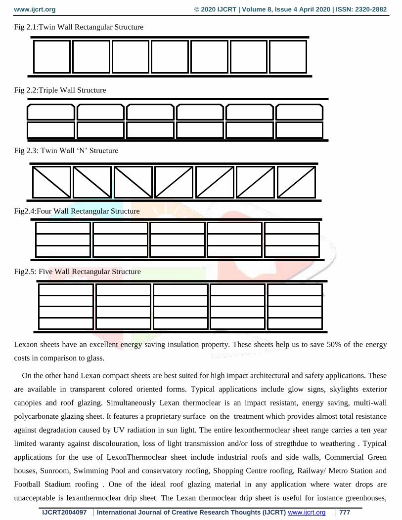
Design of Lexan multiwall sheet structures:The structured Products consists of a range of Lexan polycarbonate
sheets, profile, films and formed products for a variety of application in buildings and construction signage and other
industrial areas. Lexan polycarbonate is an amorphous thermoplastic resin which offers a unique combination of
mechanical optical, thermal and electrical properties offered by metals, glass and other plastics. Lexan sheet are 250
times stronger than glass. Thus they are virtually unbreakable. These sheets can be transparent, tinted, or in bright
opaque colors, textured, multiwall sheets and in corrugated sheets(sinusoidal/trapzoidal configurations).Lexan
Multiwall sheet structures can be represented by twin wall rectangular structure, Triple wall structure, Twin wall ‘N’
structure, Four wall rectangular structure and five wall rectangular structure as follows :
0.02 0.04 0.06 0.08 0.1 0.12 0.14 0.160.7
0.8
0.9
1
1.1
1.2
1.3
1.4
1.5
1.6
Cell depth (meter)
Cell
wid
th (
centim
ete
r)
Fig 2c: Honeycomb cell width required for convection suppression
Tilt angle =700
T= 200C
T= 400C
T= 600C
T= 800C
T=1000C
T=1200C
www.ijcrt.org © 2020 IJCRT | Volume 8, Issue 4 April 2020 | ISSN: 2320-2882
IJCRT2004097 International Journal of Creative Research Thoughts (IJCRT) www.ijcrt.org 777
Fig 2.1:Twin Wall Rectangular Structure
Fig 2.2:Triple Wall Structure
Fig 2.3: Twin Wall ‘N’ Structure
Fig2.4:Four Wall Rectangular Structure
Fig2.5: Five Wall Rectangular Structure
Lexaon sheets have an excellent energy saving insulation property. These sheets help us to save 50% of the energy
costs in comparison to glass.
On the other hand Lexan compact sheets are best suited for high impact architectural and safety applications. These
are available in transparent colored oriented forms. Typical applications include glow signs, skylights exterior
canopies and roof glazing. Simultaneously Lexan thermoclear is an impact resistant, energy saving, multi-wall
polycarbonate glazing sheet. It features a proprietary surface on the treatment which provides almost total resistance
against degradation caused by UV radiation in sun light. The entire lexonthermoclear sheet range carries a ten year
limited waranty against discolouration, loss of light transmission and/or loss of stregthdue to weathering . Typical
applications for the use of LexonThermoclear sheet include industrial roofs and side walls, Commercial Green
houses, Sunroom, Swimming Pool and conservatory roofing, Shopping Centre roofing, Railway/ Metro Station and
Football Stadium roofing . One of the ideal roof glazing material in any application where water drops are
unacceptable is lexanthermoclear drip sheet. The Lexan thermoclear drip sheet is useful for instance greenhouses,

www.ijcrt.org © 2020 IJCRT | Volume 8, Issue 4 April 2020 | ISSN: 2320-2882
IJCRT2004097 International Journal of Creative Research Thoughts (IJCRT) www.ijcrt.org 778
varanda’s, sunrooms, swimming pool enclousers, industrial roof glazing etc. one more example is lexan Profiled
sheets. This sheet does not features latter’s proprietary surface protection against UV radiation. It is used in
partitioning, shower stalls and false ceilings. In view of impact strength, The Lexan Thermoclear sheet has
outstanding impact performance over a wide range-400 C to +1200 C and also after prolonged exposure.Annual fuel
savings are strongly dependent upon building type, location and regional environment conditions. Multiwall Structure
of Lexan Thermoclear sheet offers significant advantages where thermal insulation is a major consideration. The
hollow form provides excellent insulation characteristics with heat losses significantly lower than mono-wall glazing
materials. Experimental results shows that both thermo plastics and thermo setting plastics may be highly transparent,
opaque or have any degree of clarity and light transmission in between. The total solar energy transmission may run
as high as 90% with 91-93 in the visible region (400 & 750 mm).The investigations of Raghu Raman V in 2000
shows that the industry sector in India consumes more than 51% of the commercial energy. The advisory board on
energy in 1986 has estimated that there will have to be an investment of Rs 450000 crores for achieving a production
of 450 million tons of coal for 654 billion units of power capacity. 50 million tonnes of oil was the requirement of
indiatill 2004-2005,which was reported 5156 Barrel/Day in Dec 2018 . The country is thus faced with the challenge
of meeting the serious energy short falls and economic stagnation. One of our project attempt in this direction is to
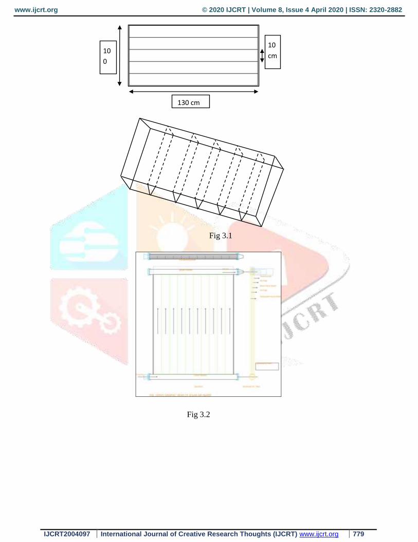
design and fabricate theNoryl Air Heater. Above said air heater consists of a plane black absorber sheet (1250 mm
1000 mm ) made of noryl plastic material. The riser tubes are channel with a square cross section and are embodied
in the absorber plate. The header tubes are PVC pipes of diameter 65 mm. The glazing is made of polycarbonate
structured materials of thickness 10 mm. The air gap between the absorber and the glazing is 10mm. The bottom
insulation is provided by the thermocole sheet of 10 mm thickness. An air gap of 10mm is provided between the
black absorber and the bottom thermo cole insulation.No way for the collector box frame is provided instead the
channel are covered with wooden frame which provides the strength. The detailed engineering drawing are given in
Fig 3.1and fig 3.2.
www.ijcrt.org © 2020 IJCRT | Volume 8, Issue 4 April 2020 | ISSN: 2320-2882
IJCRT2004097 International Journal of Creative Research Thoughts (IJCRT) www.ijcrt.org 779
Fig 3.1
Fig 3.2
130 cm
10
cm 10
0
cm
www.ijcrt.org © 2020 IJCRT | Volume 8, Issue 4 April 2020 | ISSN: 2320-2882
IJCRT2004097 International Journal of Creative Research Thoughts (IJCRT) www.ijcrt.org 780
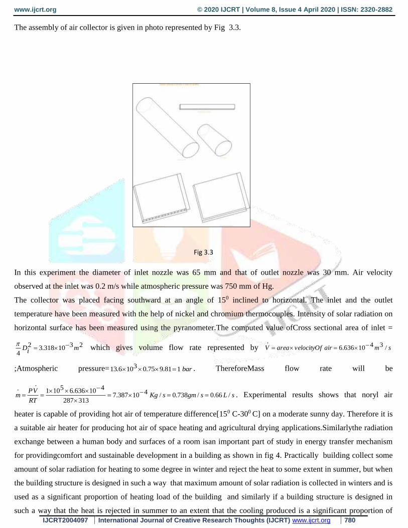
The assembly of air collector is given in photo represented by Fig 3.3.
Fig 3.3
In this experiment the diameter of inlet nozzle was 65 mm and that of outlet nozzle was 30 mm. Air velocity
observed at the inlet was 0.2 m/s while atmospheric pressure was 750 mm of Hg.
The collector was placed facing southward at an angle of 150 inclined to horizontal. The inlet and the outlet
temperature have been measured with the help of nickel and chromium thermocouples. Intensity of solar radiation on
horizontal surface has been measured using the pyranometer.The computed value ofCross sectional area of inlet =
2310318.32
4miD
which gives volume flow rate represented by smairvelocityOfareaV /3410636.6
.
;Atmospheric pressure= bar181.975.03106.13 . ThereforeMass flow rate will be
sLsgmsKgRT
VPm /66.0/738.0/410387.7
313287
410636.65101.
.
. Experimental results shows that noryl air
heater is capable of providing hot air of temperature difference[150 C-300 C] on a moderate sunny day. Therefore it is
a suitable air heater for producing hot air of space heating and agricultural drying applications.Similarlythe radiation
exchange between a human body and surfaces of a room isan important part of study in energy transfer mechanism
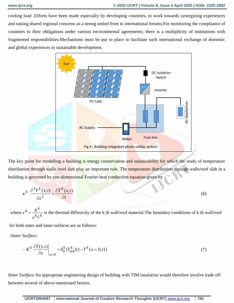
for providingcomfort and sustainable development in a building as shown in fig 4. Practically building collect some
amount of solar radiation for heating to some degree in winter and reject the heat to some extent in summer, but when
the building structure is designed in such a way that maximum amount of solar radiation is collected in winters and is
used as a significant proportion of heating load of the building and similarly if a building structure is designed in
such a way that the heat is rejected in summer to an extent that the cooling produced is a significant proportion of
www.ijcrt.org © 2020 IJCRT | Volume 8, Issue 4 April 2020 | ISSN: 2320-2882
IJCRT2004097 International Journal of Creative Research Thoughts (IJCRT) www.ijcrt.org 781
cooling load .Efforts have been made especially by developing countries, to work towards synergizing experiences
and raising shared regional concerns as a strong united front in international forums.For monitoring the compliance of
countries to their obligations under various environmental agreements; there is a multiplicity of institutions with
fragmented responsibilities.Mechanisms must be put in place to facilitate such international exchange of domestic
and global experiences in sustainable development.
The key point for modelling a building is energy conservation and sustainability for which the study of temperature
distribution through walls /roof slab play an important role. The temperature distribution through walls/roof slab in a
building is governed by one-dimensional Fourier heat conduction equation given by
t
txT
x
txT kkk
),(),(
2
2
(6)
where kCk
kKk
is the thermal diffusivity of the k th wall/roof material.The boundary conditions of k th wall/roof
for both outer and inner surfaces are as follows:
Outer Surface:
}),0()({),(
00
txTtThx
txTK kk
SAk
x
k
(7)
Inner S urface:An appropriate engineering design of building with TIM insulation would therefore involve trade off
between several of above-mentioned factors.
www.ijcrt.org © 2020 IJCRT | Volume 8, Issue 4 April 2020 | ISSN: 2320-2882
IJCRT2004097 International Journal of Creative Research Thoughts (IJCRT) www.ijcrt.org 782
))(),((),(
tTtlxThx
txTK R
kkki
lx
k
(8)
where )(tkSA
T is thesolair temperature of k th wall/roof defined as follows:
For bare walls/roof
)(0
)()( tAT
h
RtktI
tkSA
T
(9)
and for TIM insulated walls/roof
)()()(
)( tTRtI
tT A
LU
kteffk
SA
(10)
Since solar intensity and ambient air temperature are assumed to be periodic in nature, the solair temperature and
room air temperature will also be periodic and may be represented by Fourier series as follows:
N
m
timksm
ks
kSA
eTTtT1
0)( (11)
timN
mrmrR eTTtT
1
0)( (12)
Where 1)24/2( h and mikSM
ksm eTT
(13)
)( 22kmkm
kSM
BAT (14)
)(tan 1
km
kmkm
A
B (15)
kmA and kmB are Fourier coefficients of )(tT kSA and
miRmrm eTT
(16)
)( 22rmrmRm BAT (17)
)(tan 1
rm
rmrm
A
B (18)
rmA and rmB are Fourier coefficient of )(tTR . Computational results for six harmonics of the Fourier series give
the fairly good representation for the above periodic function on synthesizing. So six harmonics are considered to be

www.ijcrt.org © 2020 IJCRT | Volume 8, Issue 4 April 2020 | ISSN: 2320-2882
IJCRT2004097 International Journal of Creative Research Thoughts (IJCRT) www.ijcrt.org 783
sufficient for further computations. The validity of this consideration for solair temperature of south wall for Leh is
illustrated in Fig. 5.
Fig 5: Effect of Harmonics on solairteperature on south wall at Leh
Since solair temperature and room air temperature are assumed to be periodic in nature. So T(x, t) must also be
periodic in nature. The periodic solution of equation (1) may, therefore, be assumed as Fourier series given by
])()[(),(6
100
timkmxk
m
kmx
m
km
kkk eeBeABxAtxT
; (19)
)606024/2()1(2
1
)2
(2
1
)/(
wherei
mkimkm per second (20)
Now by using outer and inner surface boundary conditions in equation(19) and on separating time dependent and
time independent parts we get the system of equations given by
ki
ki
kk
hlh
hK0
k
k
B
A
0
0 =
0
00
rki
ks
k
Th
Th (21)
0)()(
)()(000
ksm
k
km
km
kmlk
ikm
kkmlk
ikm
k
kkm
kkkm
kTh
B
A
ehKehK
hKhK
(22)
www.ijcrt.org © 2020 IJCRT | Volume 8, Issue 4 April 2020 | ISSN: 2320-2882
IJCRT2004097 International Journal of Creative Research Thoughts (IJCRT) www.ijcrt.org 784
The heat flux entering the room through k th wall/roof is given by
timekm
kle
m
kmB
km
klek
mArTkBkAklkih
lxx
TkKtkQ )
6
1
(Re)000[()(
.
(23)
on solving matrix equations (21) and (22)we get kA0 ,
kB0 ,
kmA &
kmB ; which on substitution in equation (23) give the
heat flux entering the room through k th wall/roof.
To compute ki
A0 , k
iB
0 ,kmiA &
kmiB for TIM insulated walls we have applied outer surface boundary condition (7),
replacing 0h by LU and inner surface boundary condition (8) in equation (19) and on separating time dependent and
time independent parts we get the system of equations given by
ki
ki
Lk
hDh
UK
ki
ki
B
A
0
0=
0
0
rki
ksiL
Th
TU (24)
0)()(
)()( ksmiL
km
km
kmDk
ikm
kkmDk
ikm
k
Lkm
kL
km
kTU
B
A
ehKehK
UKUK
(25)
where D=lk+L, lk is the thickness of k th wall and L is depth of Honeycomb.
Now substituting the value ofki
A0 ,
ki
B0 ,
kmiA &
kmiB in equation (7) we get the heat flux entering the room through k
th insulated wall/roof, and is given by
timkmD
m
kmi
kmDk
mirki
ki
ki
lx
kk eeBeATBADhx
TKtQ
)(Re)[()(6
1000
.
(26)
Heat transfer between the ground and room air can be obtained by solving the Fourier heat conduction equation with
appropriate boundary conditions. Fourier heat conduction equation for the ground is
t
tyTC
y
tyTK
ggg
gg
),(),(
2
2
(27)
Heat transfer between the ground and room air temperature can be written as
)},0()({),(
0
tyTtThAy
tyTAK gRgg
y
ggg
(28)
The periodic solution for the ground temperature may be taken as
www.ijcrt.org © 2020 IJCRT | Volume 8, Issue 4 April 2020 | ISSN: 2320-2882
IJCRT2004097 International Journal of Creative Research Thoughts (IJCRT) www.ijcrt.org 785
]))[(),(6
100
timgmygm
gmy
mgmggg eeBeAByAtyT
(29)
where )1()2
()/( 2
1
2
1
im
KCimg
gggmg
(30)
Since the ground is semi-infinite medium, so as 0, 0 gAy & 0gmA . Therefore
timgmy
mgmgg eeBBtyT
6
10),( (31)
Solving equations (31), (28)& (14) and separating time dependent and time independent parts we get
00 rg TB (32)
and gmgg
rmgm
hK
TB
1 (33)
For an air condition building 0rmT , hence 0gmB
Therefore 00),( rgg TBtyT . (34)
Further the thermal load leveling factor is evaluated using formulation given by
min
.
max
.
min
.
max
.
QQLLF
(35)
ASSUMPTIONS:
The wall/roof are considered to be made of concrete material. Corresponding heat transfer coefficient and other
thermo physical parameters used in these computations are listed below:
=0.9, Kk = 0.72 W/m K, h0=22.78 W/m2 K, hi=6.82 W/m2 K, TR=293 K. (36)
Following Kaushika [14] the heat flux across the bare wall/roof slab may be expressed as follows
))()(()( tRTtkSA
TUtQ (37)
The over all heat transfer coefficient for kth bare wall/roof is given by
ihkK
kl
hU
1
0
11 (38)
www.ijcrt.org © 2020 IJCRT | Volume 8, Issue 4 April 2020 | ISSN: 2320-2882
IJCRT2004097 International Journal of Creative Research Thoughts (IJCRT) www.ijcrt.org 786
For transparently insulating a wall/roof, a TIM slab of thickness L is placed on concrete wall/roof. Air gap of 10 mm
is assumed to be maintained between the two slabs. The total heat loss coefficient (Ut) across the wall/roof clad with
TIM is given by
ihK
L
LUtU
111 (39)
and the heat flux across the insulated wall/roof slab is given by
))()(()( tRTtkSA
TtUtQ (40)
wallbarefor
wallroofinsulatedTIMfor
roofbareforKmW
R
0
/0
2/1.61
(41)
COMPUTATION AND DISCUSSION:
In above analysis, solar irradianceon the walls and roof have been evaluated using the formulations for the tilted
surface outlined in Duffie and Beckman [5] and Kaushika [14] given by
rhgdhdbhbt RtItRtItRtItI )()()()()()( (42)
Wherez
ib tR
cos
cos)( ,
2
cos1)(
tRd ,
2
)cos1(
grR ,
sinsincoscoscoscos sz , s (in degree) = )12(15 t ,
(in degree) = )365
284360sin(45.23
n,
FollowingPawan Kumar [19], the angle of incidence i (0 )90 i vary with hour angle s as :
For
tan
tancos s ;
sinsincoscoscoscoscos
sinsinsincossincoscossinsincossincoscoscos
s
ssi (43)
and for
tan
tancos s ;
sinsincoscoscoscoscos
sinsinsincossincoscossinsincossincoscoscos
s
ssi (44)
The hourly values of solar radiation intensity on horizontal surface and ambient temperature for Leh have been
obtained from Mani [2] and Bansal et. al. [18]. Monthly mean average values of solar intensity and ambient
www.ijcrt.org © 2020 IJCRT | Volume 8, Issue 4 April 2020 | ISSN: 2320-2882
IJCRT2004097 International Journal of Creative Research Thoughts (IJCRT) www.ijcrt.org 787
temperature for the hour ending at the indicated time have been used. The solar radiation intensity on horizontal
surface and ambient temperature for Boulder, USA has been derived from (Duffie and Beckman [5]) by taking mean
of weekly value of solar intensity and ambient temperature for the hour ending at the indicated time. The computation
of solar intensity and solair temperature on the surface of walls /roof involves i ; which before the time of sunrise or
after the time of sunset is either very small (less than 150) or greater than 900 . In view of the step size of one hour
(150 ) taken in computations we have neglected these values by taking Rb(t)=0 at these hours. Simultaneously we
have taken negative tilt factor to be zero.
RESULTS
First of all we evaluate solar intensity and solair temperature on the surface of wall/roof of the suggested building at
the given site and express the solair temperature on the surface of walls/roof slab in terms of six harmonics of Finite
Fourier Series. We assume underground earth as a semi -infinite medium and then compute the heat flux entering the
living space through various walls/roof slabs. As a final result we compute the load leveling factor for different
walls/roof thickness and for different depth of TIM cover.The computations have been carried out using the
MATLAB software.
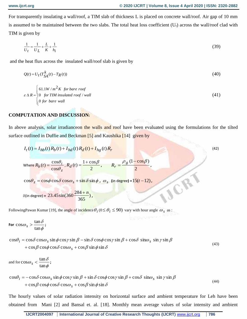
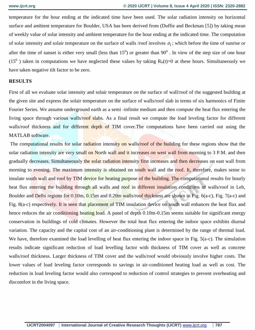
The computational results for solar radiation intensity on walls/roof of the building for these regions show that the
solar radiation intensity are very small on North wall and it increases on west wall from morning to 3 P.M. and then
gradually decreases. Simultaneously the solar radiation intensity first increases and then decreases on east wall from
morning to evening. The maximum intensity is obtained on south wall and the roof. It, therefore, makes sense to
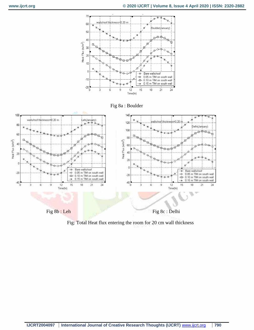
insulate south wall and roof by TIM device for heating purpose of the building. The computational results for hourly
heat flux entering the building through all walls and roof in different insulation conditions of walls/roof in Leh,
Boulder and Delhi regions for 0.10m, 0.15m and 0.20m walls/roof thickness are shown in Fig. 6(a-c), Fig. 7(a-c) and
Fig. 8(a-c) respectively. It is seen that placement of TIM insulation device on south wall enhances the heat flux and
hence reduces the air conditioning heating load. A panel of depth 0.10m-0.15m seems suitable for significant energy
conservation in buildings of cold climates. However the total heat flux entering the indoor space exhibits diurnal
variation. The capacity and the capital cost of an air-conditioning plant is determined by the range of thermal load.
We have, therefore examined the load levelling of heat flux entering the indoor space in Fig. 5(a-c). The simulation
results indicate significant reduction of load levelling factor with thickness of TIM cover as well as concrete
walls/roof thickness. Larger thickness of TIM cover and the walls/roof would obviously involve higher costs. The
lower values of load leveling factor corresponds to savings in air-conditioned heating load as well as cost. The
reduction in load leveling factor would also correspond to reduction of control strategies to prevent overheating and
discomfort in the living space.
www.ijcrt.org © 2020 IJCRT | Volume 8, Issue 4 April 2020 | ISSN: 2320-2882
IJCRT2004097 International Journal of Creative Research Thoughts (IJCRT) www.ijcrt.org 788
Fig 6a : Boulder
Fig 6b : Leh Fig 6c : Delhi
Fig 6 : Total heat flux entering the room for 10cm wall thickness
www.ijcrt.org © 2020 IJCRT | Volume 8, Issue 4 April 2020 | ISSN: 2320-2882
IJCRT2004097 International Journal of Creative Research Thoughts (IJCRT) www.ijcrt.org 789
Fig 7a : Boulder
Fig 7b : Leh Fig 7c : Delhi
Fig 7 : Total heat flux in the room for 15 cm wall thickness
www.ijcrt.org © 2020 IJCRT | Volume 8, Issue 4 April 2020 | ISSN: 2320-2882
IJCRT2004097 International Journal of Creative Research Thoughts (IJCRT) www.ijcrt.org 790
Fig 8a : Boulder
Fig 8b : Leh Fig 8c : Delhi
Fig: Total Heat flux entering the room for 20 cm wall thickness

www.ijcrt.org © 2020 IJCRT | Volume 8, Issue 4 April 2020 | ISSN: 2320-2882
IJCRT2004097 International Journal of Creative Research Thoughts (IJCRT) www.ijcrt.org 791
Fig 8a : Boulder
Fig 8b :Leh Fig 8b : Delhi
Fig 8 : Variation of LLF for heat flux entering the room
References
[1] A.K. Athienitis and H. Ramadan. Numerical Model of a building with TransparentInsulation. ISES Solar World
Congress ,VolumeII (1999).
[2] A. Mani, Hand book of Solar Radiation data for India. Allied Publishers, New Delhi, (1980).
www.ijcrt.org © 2020 IJCRT | Volume 8, Issue 4 April 2020 | ISSN: 2320-2882
IJCRT2004097 International Journal of Creative Research Thoughts (IJCRT) www.ijcrt.org 792
[3] F. Trombe, US Patent 3, 832, 992 (1972).
[4] H.C. Hay and J.I. Yellot, Natural air conditioning with roof pools and movable insulation, Ashrae trans.75, 165
(1959).
[5] J.A.Duffie and W.A. Beckman, Solar Engineering of Thermal Processes. John Wiley and Sons., New York
(1980).
[6] K.G.T. Hollands, K.N. Marshall, and R.K. Wedel, An approximate equation for predicting the solar transmittance
of transparent honeycombs. Solar Energy 21, 231-236 (1978).
[7] K.G.T. Hollands, G.D. Raithby, F. B. Russell and R.G. Wilkinson, Coupled radiative and conductive heat
transfer across honeycomb panels and through single cells. Int. J. Heat and Mass Transfer 27, 2119-2131 (1984).
[8] M. S. Sodha, S. C. Kaushik and J. K. Nayak, Performance of Trombe walls and roof pond systems, Applied
Energy 8, 175 (1981).
[9] M. S. Sodha, S. C. Bhardwaj and S.C. Kaushik,Thermal load leveling of heat flux through an insulatedthermal
storage water wall, Int J.Energy Res. 5, 155 (1981).
[10] M. Arulanantham and N.D Kaushika. Global Radiation Transmittance of transparent insulationmaterials. Solar
Energy 53, 323-328 (1994).
[11] M.Arulanantham and N.D. Kaushika, Coupled Radiative and Conductive Thermal Transfer Across Transparent
Honeycomb Insulation Materials. Applied Thermal Engineering 16(3), 209-217 (1996).
[12] M.Karmele Urbikain, Morris G. Davies, One -Dimensional solutions to Fourier’s equation and measures of heat
transmission through walls:The Role of wall decay times. Building and Environment 43, 1433-1445 (2008)
[13] N.D.Kaushika, M. S. Sharma and S. Kaul, Honeycomb roof cover system for passive solar space heating,
Energy Convers.Manag.27, 98-102 (1987).
[14] N. D Kaushika, Principles and Applications of Solar Energy. Geo. Environ Academia and IBTPublishers, Delhi,
India (1988)
[15] N. D. Kaushika, P. K. Sharma and R. Padma Priya, Solar thermal analysis of honeycomb roof cover system for
energy conservation in an air –conditioned building, Energy and Buildings18, 45-49. (1992).
[16] N.D. Kaushika, Pawan Kumar and M. Arulanantham, Solar diffuse radiation transmittance of transparent
insulation materials devices. Proceedings of all India seminar on advances in solar energy technologies, Jodhpur,
India, January 29-30 ( 2002).
[17] N.D. Kaushika and K. Sumathy, Solar Transparent Insulation materials: a review, Renewable and Sustainable
Energy Reviews 7, 317-351(2003)
www.ijcrt.org © 2020 IJCRT | Volume 8, Issue 4 April 2020 | ISSN: 2320-2882
IJCRT2004097 International Journal of Creative Research Thoughts (IJCRT) www.ijcrt.org 793
[18] N.K Bansal, S.N.Garg, N. Lugani and M. S. Bhandari, Determination of glazing area in direct gainsystems for
three different climatic zones, Solar Energy53(1), 81-90 (1994).
[19] Pawan Kumar and Kaushika N D .2005. Convective effect in air layers bound by cellular arrays . Journal of scientific and
industrial research.Vol 64 ,Aug 2005,pp 602-612.
[20] Pawan Kumar, Modelling of Fluid Mechanical and Heat Transfer Processes in Transparent Honeycomb
Insulations Materials Devices and Systems, Ph.D Thesis, IIT Hauz Khas, New Delhi -110016, INDIA, July 2005.
[21] R Fuchs and J.F. McClelland, Passive solar heating of building using a transwall structure, SolarEnergy 23, 123
(1979).
![First-principles simulation and experimental evidence for ...transparent conductive oxide (TCO) film applied in electronic devices[2−7], such as light emitting devices, low emissivity](https://img.pdfslide.net/doc/110x75/60802e232060c100ec114fb4/first-principles-simulation-and-experimental-evidence-for-transparent-conductive.jpg)