Embed Size (px)
Citation preview

Transponder Standing Committee
Stuttgart, Oct. 21, 2019
Agenda:
Where are we in terms of projects applications?
- cross-fertilization between Laser Comm. and ranging has not (yet) happened
- LRO (one-way ranging) finished
- T2L2 (time transfer) finished
- ACES (time transfer) upcoming (but very slow)
- New applications? (quantum cryptography…)
At this point in time we are only dealing with time transfer

https://imgur.com/RaWqYkV
Time, frequency and optical time transfer
• Clocks probe the local physics (gravity and velocity)
• Clock oscillator performance demonstrated to 1 part in 1018
• Frequency transfer over fiber links theoretically stable to 1 part 1019
• Optical time transfer (ground to satellite on T2L2 ≈ 7 ps @ 30s)
• Coherent optical round trip time transfer (2 km free space on ground: 1 fs @ 1000 s)
• 2-way optical time transfer on a compensated fiber link (600 m) achieved stability of 1 ps over several weeks.
… this can be the beginning of a relativistic (space-time) geodesy

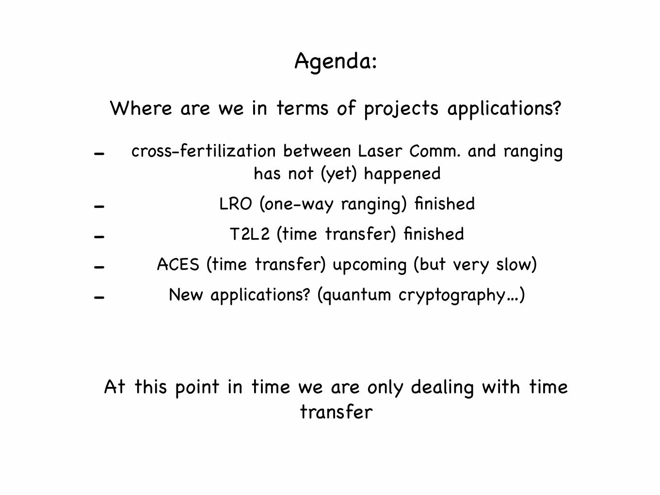
Coherence is given then the different delays ei are always known to:
A common clock has the advantagethat the instrumentation measurescoherently (no clock adjustments are required)
Closure measurements allow the determination of (variable) biases
Frequency is used to provide a scale
The phase angle provides the time in one spott
τ i (t) ≤∂ei∂t
The instrumentation of an observatory isnot in one spot


2WSTFT und ELTlaufen gemeinsam

Laser SystemName TBDDescription YAGZ136 Standard Z136.1-2014Analysis Type Single WavelenthLaserWavelength 1064 nmPulse Mode MultiPulsePulse Width 12 psPulse Repetition Rate 100 Hz
average Power EnergyEnergy per pulse mJ 1,00E+00Average Power mW 1,00E+02Divergence half-angle in µrad 100 100Divergence half-angle in rad 0,0001 0,0001Distance Laser - Observer km 400 400MPE limit to be used (12 ps to 13 µs pulse) 2,00E-06MPE limit to be used (>10 sec) W/cm2 5,06E-03
atmospheric attenuation (Transmission 60 to 80%)per ANSI-Z136.6 C4.1.3. Upward directed Beam 0,8 0,8
Radiant exposure at ISS distance (crew unaided eye)
energy (in J) * transmission / ((tan half-angle * distance (in cm))^2 * pi) [J/cm²] 1,59155E-11
Radiant exposure at ISS distance (crew unaided eye)
power (in W) * transmission / ((tan half-angle * distance (in cm))^2 * pi) [W/cm²] 1,59155E-09
Required ELT detector energy level @ ISS [J/cm²] N.A. 2,30E-13Impact of crew using Telescope
Objective Diameter mm 400 400Objective Entry Surface cm² 1256,637061 1256,637061
FILL OUT THE GREY FIELDS TO CHECK, IF YOUR LASER IS SUITABLE FOR ELT
ELT Laser Energy and average Power Assessment

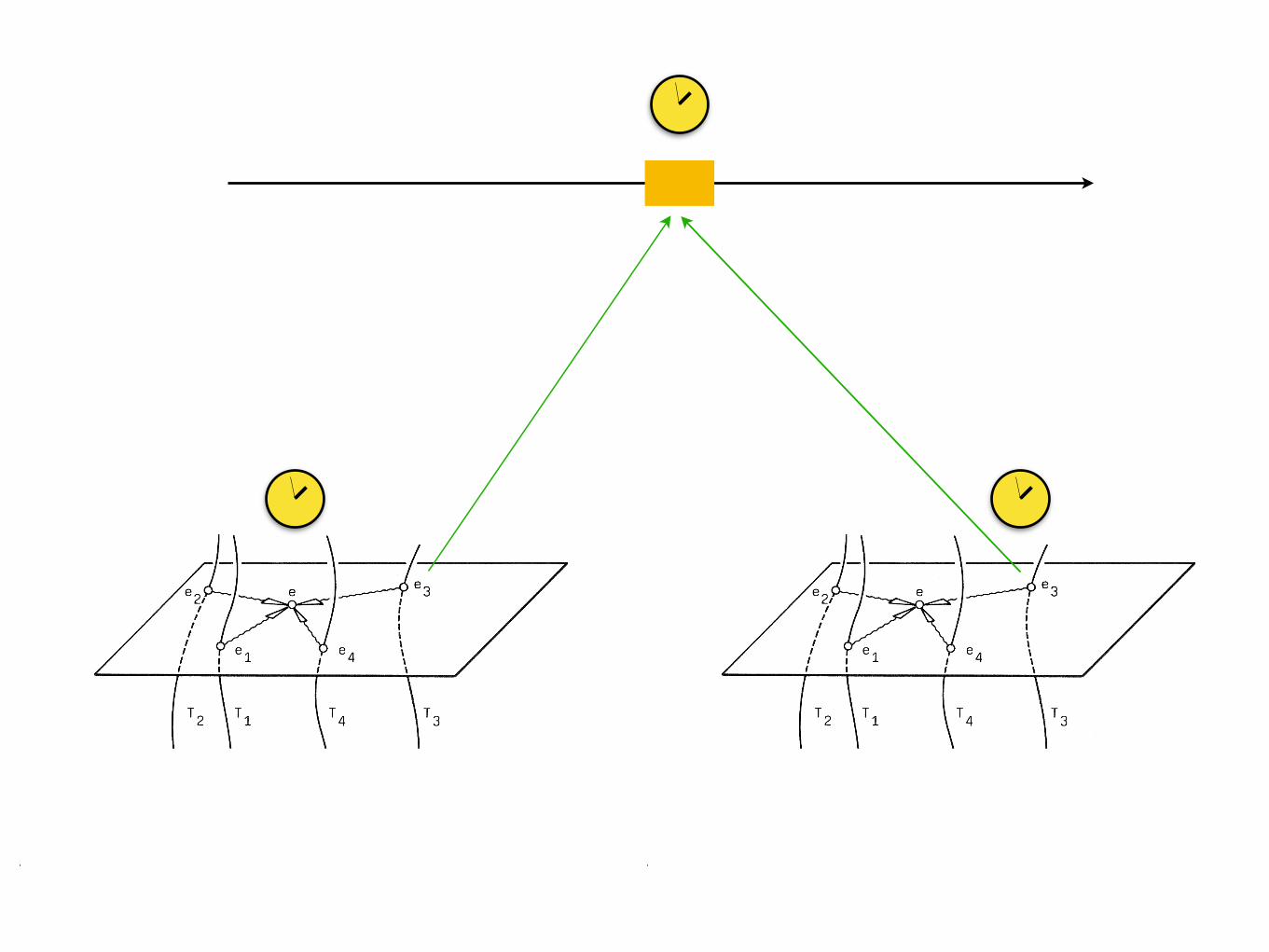
Transponder SC - Local Time Distribution
Jan Kodet, K. Ulrich SchreibeTechnische Universität München, GO- Wettzell

CLOCK
timeToAslr ToAgnss ToAVLBI𝜏2𝜏1 𝜏3 𝜏4
Gola isτ1=τ2=τ3=τ4=const.
τI1, τI2, τI3 - proper calibration
τI1 τI2τI3
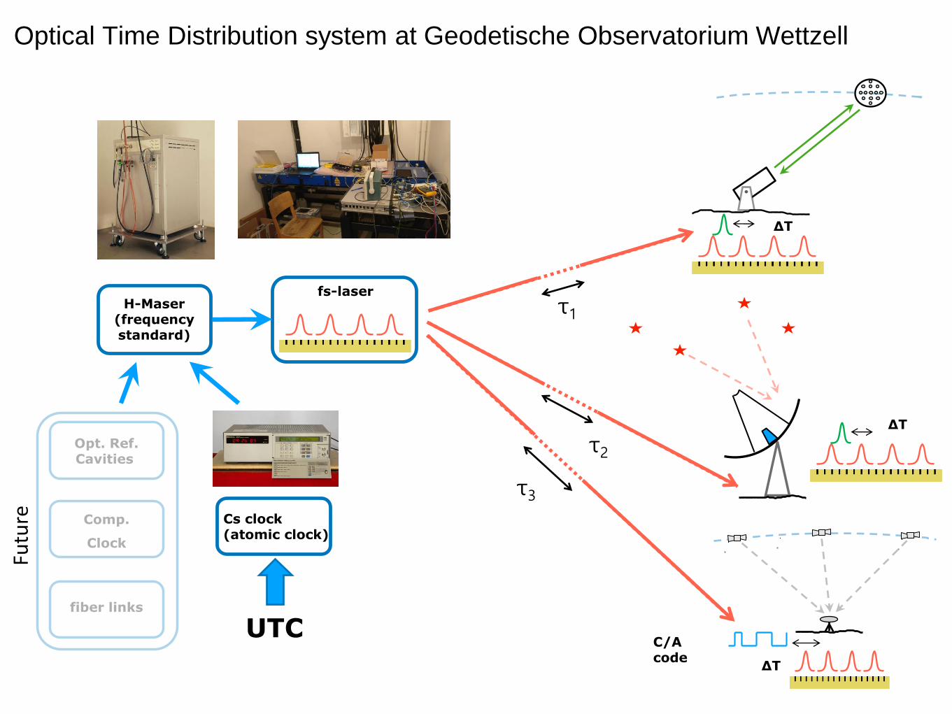
H-Maser(frequency standard)
Cs clock(atomic clock)
UTC
fs-laser
Optical Time Distribution system at Geodetische Observatorium Wettzell
ΔT
C/A code
ΔT
ΔT
τ3
τ2
τ1
Opt. Ref.Cavities
fiber links
Comp.
Clock
Future

Geodetic Observatory Wettzell

Back-end
PPS Electronic
100 MHz VCO
10 MHz VCO
÷2
100 MHz 10dBm
10 MHz 10dBm
5 MHz 10dBm
LED1..3 2xFAST PPS CMOS PPS
100 MHz PLLPD
Back-end diagram
100 MHz Optical input
@1560 nmPLL
sfp
transceiver
Optical modulated signal
@1310 nm
• FAST PPS1 - CML logic terminated by 50 Ohm
• FAST PPS2 - AC coupled PECL logic.
• 1 channel CMOS PPS terminated by 50 Ohm.
Noise-eater

Error signal and time distribution of stationary link
To validate new timing system in terms of stability and absolute delay we developedTWOTT system Event Timer NPET. J. Kodet et al., Metrologia, 2016.
NPET TWOTT terminal

Time distribution of stationary link
Maser room AC failure

1
Transponder standing committee
Clément COURDE1, Julien CHABE1, Jean-Marie TORRE1, Duy-Hà PHUNG1, Etienne
SAMAIN2, Michel ABGRALL3, Daniele ROVERA3, Hervé Mariey, Mourad Aimar,
Nicolas Maurice, Hervé Viot, Julien Scariot, Grégoire Martinot-Lagarde
1 Université Côte d'Azur, CNRS, Observatoire de la Côte d'Azur, IRD, Géoazur2 SigmaWorks
3 SYRTE, Observatoire de Paris, Université PSL, CNRS, Sorbonne Université, LNE
ILRS Technical Workshop
Stuttgart 21th – 25th October 2019

2
ESA context
Call for tender
January 2019

3
Time Transfer on Galileo satellites
- Ground-Space Time Transfer & Ground-Ground Time Transfer
- RF TT & optical TT comparison with improved accuracy
- Improved performance in non common view thanks to better space
clocks (H-Maser compared to USO performances)
- Higher number of stations visibles for common view measurements
and longer integration time thanks to the higher altitude of Galileo
satellite (23320 m) compared to Jason-2 or the ISS
- 3D localization in space with synchronized SLR stations and by
ranging simultaneously on a satellite equipped with an Active-LRR
- Clock behaviour in the space environment
4
Conclusions & Perspectives
ESA interests to have optical time transfer instrument on
Galileo as scientific payload.
=> New opportunity for optical Time Transfer
=> Coordinate Eurolas/ILRS answer ?
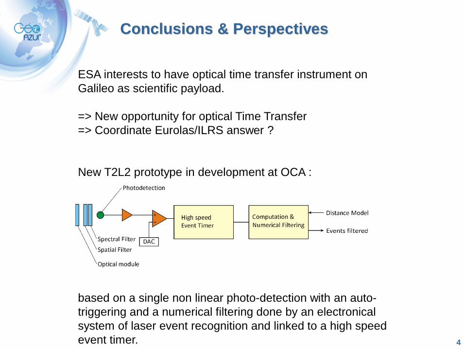
New T2L2 prototype in development at OCA :
based on a single non linear photo-detection with an auto-
triggering and a numerical filtering done by an electronical
system of laser event recognition and linked to a high speed
event timer.