Embed Size (px)
Citation preview

©2009 Old City Publishing, Inc.Published by license under the OCP Science imprint,
a member of the Old City Publishing Group.
I. J. Trans. Phenomena, Vol. 11, pp. 39–50Reprints available directly from the publisherPhotocopying permitted by license only
39
*Corresponding author: [email protected]
INTRODUCTION
Methane is usually converted into H2, CO and CO2 by employing Ni as a catalyst supported by alumina in the reformers. Such reformers have been developed during last years. In general, technologies to produce hydrogen from methane are based on one of the follow-ing conventional processes: steam methane reforming (SMR), partial oxidation (POX), autothermal reforming (ATR) [1].
There is an increasing interest worldwide in the development of innovative fuel processing technolo-gies for fuel cell systems, for instance, compact
reformer (CR hereafter) for a variety of applications. The basic idea of the CR is, by applying thin coatings of catalyst, to catalytically activate both sides of a compact heat exchanger – one side for combustion to provide heat for the other side to sustain steam reform-ing of methane and produce hydrogen. In this configu-ration, the thin coating results in small thermal conduction and species diffusion path lengths that largely eliminate heat and mass transfer restrictions associated with conventional reformers, and an improved utilization of the intrinsic reforming catalyst kinetics is allowed to achieve an efficient transfer of thermal energy. The compact reformer concept and its
Transport Phenomena Coupled by Chemical Reactions in Methane Reforming Ducts
J. YuAN1*, X. LV2, D. Yue2 AND B. SuNDéN1
1Department of Energy Sciences, Faculty of Engineering, Lund University, Box 118, 22100 Lund, SWEDEN
2Marine Engineering College, Dalian Maritime University, Dalian 116026, China
Mass, heat and momentum transport processes are strongly coupled with catalytic chemical reactions in a methane steam reforming duct. In this paper, a three-dimen-sional calculation method is developed to simulate and analyze reforming reactions of methane, and the effects on various transport processes in a steam reforming duct. The results show that the design and operating parameters grouped as characteristic ratios have significant effects on the transport phenomena.
Keywords: transport phenomena, chemical reactions, reformer, CFD, analysis, characteristic parameters.

40 J. YuAN et al.
potential high power density could lead to major appli-cation in fuel cell systems for stationary and transpor-tation applications [2–4]. For instance, coupling of steam reforming and catalytic combustion in adjacent ducts received attention recently, and an excellent review can be found in [5] regarding the CR concept application and new design development. However, literature review shows that the research on the kinetic reaction performance and effects on the transport pro-cesses are very limited.
In this study, a three-dimensional computational procedure is developed to simulate and analyze steam reforming of methane in a composite domain consist-ing of a porous active layer, a gas flow duct and solid plates. The reformer conditions such as the combined thermal boundary conditions (heat flux on the active solid wall and thermal insulation on the other solid walls), mass balances associated with the reforming reactions and gas permeation to/from the porous cata-lyst layer are applied in the analysis. Momentum and heat transport together with fuel gas species equations have been solved by coupled source terms and variable thermo-physical properties (such as density, viscosity, specific heat, etc.) of the fuel gas mixture. It should be mentioned that various transport phenomena coupled by the chemical reactions of methane in the reformer is concentrated and presented in this paper.
PRObleM sTaTeMeNT aND MaTheMaTICal MODelINg
A three-dimensional computational fluid dynamics (CFD) code is employed for a methane reforming duct from a typical compact reformer, as shown in Fig. 1. The U, V, and W are the velocity components in the x, y, z directions, respectively. In this study, the porous catalyst layer is assumed to be homogeneous and characterized by effective parameters and the fuel in the porous layer is in thermal equilibrium with the solid matrix. The reforming reactions are within the porous catalyst layer. A constant flow rate U = Uin with mole fractions of the mixed fuel is specified at the inlet of the fuel flow duct, while U = 0 is specified at the inlet for the solid walls and the porous catalyst layer. Only half of the duct is considered by imposing symmetry conditions on the mid-plane, as shown in Fig. 1.
There are several transport processes (such as mass, heat and momentum transport) together with chemical reactions appearing in multifunctional reactors. It is often found that endothermic and exothermic reactions are strongly coupled by heat exchange in the reactors, such as hydrocarbon cracking, steam reforming and dehydrogenation. In a catalytic reformer, there are many reactions taking place. It is a fact that [1, 5–6] the
FIGuRe 1Scheme of an investigated duct of steam reforming reactors.

TRANSPORT PHeNOMeNA COuPLeD BY CHeMICAL ReACTIONS IN MeTHANe ReFORMING DuCTS 41
steam reforming, water gas-shift, and reverse methana-tion reactions of methane are the major ones with sig-nificant reaction rates, while other side reactions include cracking of methane and carbon monoxide to carbon deposition, and gasifying carbon by steam with very low reaction rates. The above mentioned side reactions can then be ignored and only the following major chemical reactions are included in this study:
Methane steam reforming:
(1)
Water gas-shift:
(2)
Reverse methanation:
(3)
It is clear that the above processes in eqs. (1) and (3) are endothermic and the overall balance of the reactions requires net heat input by the catalytic com-bustion in the adjacent ducts. This heat supply is rep-resented by a heat flux qb in this study.
The governing equations to be solved are the gen-eral ones including continuity, momentum, energy and species equations. These equations together with specific source terms have been documented in, e.g., [7], and are not repeated here. It should be mentioned that the inclusion of the source term in the momen-tum equation allows it to be valid for both the porous catalytic layer and the fuel gas flow duct. For the fuel (or gas) flow duct, the source term becomes zero and this equation then reduces to the regular Navier-Stokes equation. For the porous layer, the source term is not zero, and the momentum equation with non-zero source term can be regarded as a generalized Brinkman-Forchheimer-extended Darcy model. For more details, see [8, 9] and the references included there. It accounts for the macroscopic inertial effects and shear stresses, and microscopic inertial effects as well.
4 2 2 (298K)3 ,226000 kJ/kmol
CH H O CO H h+ → + ∆=
2 2 2 (298K),41000 kJ/kmol
CO H O CO H h+ → + ∆=-
(298K)2 4 ,165000 kJ/kmol
4 2 2 2CH H O CO H h+ → + ∆=
Based on the thermal equilibrium assumption, only one set energy equation is solved to balance the con-vected energy, the heat conduction through the solid and the gas mixture, the energy due to fuel gas species diffusion, and a source term ST. The heat source term is associated with the steam reforming, water gas-shift and reverse methanation reactions,
(4)
where Ri is the reaction related mole fluxes, and ∆hreaction,i is the reaction enthalpy. The species mass conservation equations are formulated in a general form as well for H2, CH4, CO and H2O, respectively, i.e., for n-1 species where n is the total number of spe-cies involved in the fuel gas mixture. The last species (CO2) can be solved because the sum of the mass frac-tions equals one.
It is a fact that mass diffusion is a process leading to equalization of substance concentration or estab-lishing an equilibrium gas distribution that results from random migration of the species. Molecular dif-fusion occurs as a result of thermal motion of the mol-ecules, and the flux of the species i is proportional to the concentration gradient and diffusion coefficient. One of the significant challenges in fuel reforming modelling is in determining the rate at which the spe-cies diffuse and gases convect in the fuel flow ducts and porous catalytic areas. The Stefan-Maxwell model is more commonly used in multi-component system, as in this study. The diffusion coefficients of species i in the fuel gas flow duct are calculated by the expres-sion based on the binary coefficients [10]
(5)
where DA,gm is the diffusion coefficient of the compo-nent A in the mixture with B, C, …, XA, XB, XC are the molar fraction of the appropriate species, and DAB and DAC are the diffusion coefficients in the AB and AC binary system, respectively. It is clear that for an n component system, n(n-1)/2 binary diffusivities are required.
There exist various reaction kinetics and rate/equi-librium constants reported in the literature for the reactions. In this study, the following reaction rates are employed to express the kinetic rates of absorption or
,T i reaction ii
S R h= ∆∑
,
1
/ / ...A
A gmB AB C AC
XD
X D X D
-=
+ +

42 J. YuAN et al.
production of the gas species, based on partial pres-sure, temperature and species compositions for the chemical reactions (1)-(3):
(6)
(7)
(8)
in which, mcl is the catalyst loading (kgcat/m3), and
Den 2 2
1 CO CO H HK p K p= + +4 4 2 2 2
/CH CH H O H O HK p K p p+ + . The values of the pre-exponential factors, activation energies, equilibrium constants, and heat of adsorp-tion are given in Table 1 and Table 2, respectively.
In the species mass conservation equations, the source terms Ss,i read:
Den
2
4 2
2
3
12.5
,1 31 2
, kmol/(m s)( )
H CO
CH H OeH
cl
p pkp p
KpR m
- =
Den
2 2
2
2
2
,2 32 2
, kmol/( m s)( )
H CO
CO H OH e
cl
p pkp p
p KR m
- =
Den
2 2
4 2
2
423
3.5,3 3
3 cl2m , kmol/( m s)
( )
H CO
CH H OeH
p pkp p
KpR
- =
(9)
Based on the reforming reaction function, the ther-mal and fuel gas mass concentration/flux boundary conditions at the walls are specified as follows. At the bottom wall (y = 0):
(10)
at the top and side walls:
(11)
at the mid-plane (z=a/2):
(12)
NUMeRICal sOlUTION MeThODOlOgy
A three-dimensional computation fluid dynamics (CFD) code is applied to solve the governing equations together with the boundary conditions (10–12). The employed code is a general purpose one and based on the finite-volume technique with boundary fitted coordinates for solving the differential equations. The Cartesian coordinate system in the physical space is replaced by a general non-orthogonal coordinate sys-tem. The momentum equations are solved for the veloc-ity components on a non-staggered grid arrangement. The Rhie-Chow interpolation method is used to com-pute the velocity components at the control volume faces. Algorithms based on the TDMA and a modified SIP are employed for solving the algebraic equations. In this study, the convective terms are treated by the QuICK scheme, while the diffusive terms are treated by the central difference scheme. The SIMPLeC algo-rithm handles the linkage between velocities and pres-sure. More details can be found in, e.g., [7].
2 2
4 4
2 2
1 2 3
1 3
1 2 3
1 2
(3 4 )
( )
( )
( )
s,H H
s,CH CH
s,H O H O
s,CO CO
S R R R M ;
S R R M ;
S R R 2R M ;
S R R M
= + +
= - -
= - - -
= -
, 2 2 4
0; - ;
( H , CO, H O and CH )
b eff i
ieff i eff
TU V W q k J
yY
D iy
ρ
∂= = = =
∂∂
=- =∂
0, 0, 0iU V W q J= = = = =
0iYU V TW
z z z z
∂∂ ∂ ∂= = = = =
∂ ∂ ∂ ∂
TABLe 1Kinetic Parameters and equilibrium constants [5]
Reaction Kinetic rate constant ki (kmol/kgcath)
equilibrium constant Kej
Steam reforming
4.225×10¹⁵ ×e(-240100/RT)
5.75 × 10¹² ×e(-11476/RT), bar2
Watergas-shift
1.955×10⁶ × e(-67130/RT)
1.26 × 10⁻² ×e(4639/RT)
Reverse methanation
1.02×10¹⁵ × e(-243900/RT)
7.24 × 10¹⁰ × e(-21646/RT), bar2
TABLe 2Adsorption constants Ki [5]
Species CH4 CO H2 H2O
Ki 6.65 ×10⁻⁴ × e(-38280/RT),
bar-1
8.23 ×10⁻⁵ × e(-70650/RT),
bar-1
6.12 ×10⁻⁹ × e(-82900/RT), bar-1
1.77 ×10⁵ × e(88680/RT),
-

TRANSPORT PHeNOMeNA COuPLeD BY CHeMICAL ReACTIONS IN MeTHANe ReFORMING DuCTS 43
As shown in [7], the equations to be calculated are coupled by temperature, partial pressure/concentra-tion of gas species via source terms and thermal-phys-ical properties. It should be mentioned that no gas flow is present in the solid plates. Only the heat conduction equation, derived from the energy equation, is solved for this domain. The thermal-physical properties of the gas mixture are variables. These parameters depend on the position in the duct, and the species mass frac-tion and/or temperature as well. Fuel gas mixture den-sity, viscosity and specific heat are then calculated and updated during the calculations. In this investigation, a uniform grid point distribution in the cross section is applied. To obtain finer meshes in the entrance region of the duct, a non-uniform distribution of grid points with an expansion factor is implemented for the main flow direction. Various values of the expansion factor have been checked and 1.01 was found to be sufficient to achieve grid independent solutions.
ResUlTs aND DIsCUssION
Parameters of a typical reforming duct are applied as a base case in this study, while the parameter stud-ies are conducted for various duct configuration and operating conditions to compare with. The base geom-etry parameters are shown in Table 3. For the porous layer, the parameters are chosen as: porosity ε = 0.5, permeability β = 2 × 10⁻¹⁰ m2, and catalyst loading mcl = 0.1gcat/cm3. The binary diffusion coefficients of the fuel species are shown in Table 4 [11]. Fuel inlet temperature Tin = 650oC; inlet mole concentration H2:CH4:CO:H2O:CO2 = 0.026:0.2470:0:0.7145:0.0125 with Uin = 5 m/s. It should be noted that all the results for the base case was presented in [7], and are not repeated in this paper.
Three characteristic ratios, having significant effects on various transport processes and chemical reactions as discussed later in this paper, are defined in this study. These are the hydraulic diameter ratio Dhr (ratio of the porous layer diameter to the flow duct diameter), the permeation length ratio PLr (ratio of the fuel flow duct width to the porous catalyst layer width), and the permeation rate ratio PRr (ratio of the entrance pressure gradient to permeation resistance).
(13)
(14)
(15)
Dhp in eq. (13) is the hydraulic diameter of the porous catalyst layer (Dhp = 4bhp/(2(b + hp))), Dhd the hydrau-lic diameter of the fuel flow duct (Dhd = 4ahd/(2(a + hd))); a in eq. (14) is the width of gas flow duct, b the width of the porous catalyst layer; hp in eq. (15) is the thickness of the porous layer. It is clear that both diameter ratio Dhr and permeation length ratio PLr are related to the fuel flow duct and catalytic porous layer configurations, to account for the charac-teristics of the permeation area and length, respec-tively. The permeation rate ratio PRr considers the characteristics of the catalytic porous material (such as the permeability βi) and duct operation parameter (such as the inlet velocity Uin).
To investigate effects of the diameter ratio on the transport phenomena and reformer performance, the
/hr hp hdD D D=
/rPL a b=
2( / 2 ) / ( / )( ) / (2 )
in p in i
i in p
PRr U h UU h
= ρ µ β= ρβ µ
TABLe 4Binary diffusivity of the ith fuel gas species
i/j Di,j (m2/s) i/j Di,j (m2/s)
CH4/CO 3.47e-05 CO/H2 11.92e-05
CH4/H2O 4.30e-05 CO/CO2 2.59e-05
CH4/H2 11.04e-05 H2O/H2 14.10e-05
CH4/CO2 2.88e-05 H2O/CO2 3.38e-05
CO/ H2O 4.15e-05 H2/CO2 10.23e-05
TABLe 3Geometries of the reforming reaction duct (cm)
Length (x) Depth (y) Width (z)
Overall Duct 20 1 1
Fuel Flow Duct 20 0.4 0.8
Porous CatalyticLayer
20 0.4 1

44 J. YuAN et al.
height of fuel flow duct hd was varied. Figure 2 shows velocity contours for the cases of Dhr = 1.17 (hd = 3.5 mm) and Dhr = 0.99 (hd = 4.5 mm). As shown by dashed lines, the base case (Dhr = 1.07, hd = 4 mm) is present as well in Fig. 2. It should be noted that the height of the upper solid plate was changed accordingly to keep the total height of the upper solid plate and the fuel flow duct constant.
As shown in Fig. 2, the velocity contours for big or small Dhr have a similar trend as that of the base case, i.e., there is no symmetry of the axial velocity and the position of the maximum values shifts away from the physically central plane. This effect is more signifi-cant for the big Dhr case (Fig. 2a), if compared to the one with small Dhr (Fig. 2b). More critically, more fuel is permeated to and kept in the porous reaction region, as shown in Fig. 2a with smaller velocity contours than those in Fig. 2b. This may be due to the fact that the fuel flow duct in Fig. 2a is small if compared to the porous catalyst layer.
effects of the permeation length ratio have been investigated as well by varying the width of the fuel flow duct a, while other ratios were kept constant. Per-meation length ratios PLr = 0.6 (a = 3 mm) and PLr = 0.9 (a = 4.5 mm) were employed, and the pre-
dicted performance is compared with that of the base case (PLr = 0.8, a = 4 mm). From Fig. 3, it is found that the cross-section velocity profiles are similar to each other for different permeation length ratios. Moreover, the steam reforming reaction rate for the case with small permeation length ratio (Fig. 4a) is almost in the same order as that achieved in the case with big permeation length ratio (Fig. 4b).
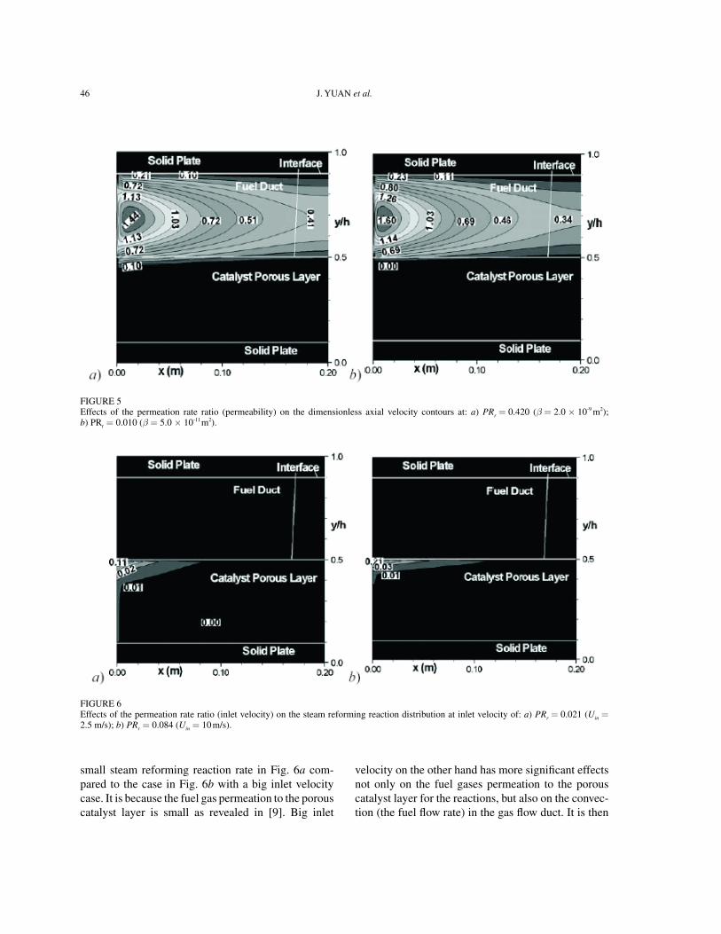
The effects of the permeation rate ratio on the fuel gas flow are shown and discussed in the following sec-tion. It is noted from Fig. 5a that, by increasing the permeability, fuel gas permeation to the porous layer is big, i.e., the length having a axial velocity in the porous layer close to the fuel flow duct is longer, if compared to the case with a small permeability shown in Fig. 5b. This is so because the permeability is a term used for the conductivity of the porous medium with respect to permeation by a fluid. It is known that a big permeability of a porous layer allows more gas to pass at the same pressure gradient. Consequently, more fuel gas is permeated from the fuel flow duct, and the gas convection can be found with bigger velocities in the porous layer close to the fuel flow duct at the entrance region. Certain impacts on the change of the axial velocity distribution are expected
FIGuRe 2Velocity contours for the cases of: a) Dhr = 1.17; b) Dhr = 0.99.

TRANSPORT PHeNOMeNA COuPLeD BY CHeMICAL ReACTIONS IN MeTHANe ReFORMING DuCTS 45
for both the fuel flow duct and the porous catalytic layer, when the permeability is large.
effects of inlet velocity on the reforming perfor-mance are shown in Figs. 6 and 7. Permeation rate
ratios PRr = 0.021 (Uin = 2.5 m/s) and PRr = 0.084 (Uin = 10 m/s) have been employed to compare with each other, i.e., PRr = 0.042 and Uin = 5 m/s. It is revealed that, in the entrance region, small PRr has a
FIGuRe 3Distribution of velocity contours at the inlet cross section for the cases of: a) PLr = 0.6; b) PLr = 0.9.
FIGuRe 4Distribution of steam reforming reaction at the inlet cross section for the cases of: a) PLr = 0.6; b) PLr = 0.9.
46 J. YuAN et al.
small steam reforming reaction rate in Fig. 6a com-pared to the case in Fig. 6b with a big inlet velocity case. It is because the fuel gas permeation to the porous catalyst layer is small as revealed in [9]. Big inlet
velocity on the other hand has more significant effects not only on the fuel gases permeation to the porous catalyst layer for the reactions, but also on the convec-tion (the fuel flow rate) in the gas flow duct. It is then
FIGuRe 5effects of the permeation rate ratio (permeability) on the dimensionless axial velocity contours at: a) PRr = 0.420 (β = 2.0 × 10⁻⁹ m2); b) PRr = 0.010 (β = 5.0 × 10⁻¹¹ m2).
FIGuRe 6effects of the permeation rate ratio (inlet velocity) on the steam reforming reaction distribution at inlet velocity of: a) PRr = 0.021 (Uin = 2.5 m/s); b) PRr = 0.084 (Uin = 10 m/s).

TRANSPORT PHeNOMeNA COuPLeD BY CHeMICAL ReACTIONS IN MeTHANe ReFORMING DuCTS 47
FIGuRe 7effects of the permeation rate ratio (inlet velocity) on the H2 distribution at inlet velocity of: a) PRr = 0.021 (Uin = 2.5 m/s); b) PRr = 0.084 (Uin = 10 m/s).
FIGuRe 8effects of the permeation rate ratio (thickness of the porous layer) on the H2 distribution. a) PRr = 0.084 (hp = 2.0 mm); b) PRr = 0.168 (hp = 1.0 mm).
noted from Fig. 7a that the exit H2 mole fraction is high even the reforming reaction rate is small com-pared to the case in Fig. 7b. It means that the H2 yield is controlled by the combined effects of the reforming reactions in the porous catalyst layer and convective
flow (the fuel flow rate) along the flow direction down-stream the fuel gas flow duct.
As expected, thickness of the porous catalyst layer is one of the most important parameters. To investi-gate effects of the porous layer thickness on the gas

48 J. YuAN et al.
flow and the reformer reactions, the height of porous layer hp was varied while other parameter ratios were kept constant. It should be mentioned that the thick-ness of the lower solid plate was changed accordingly to keep the total height of the porous catalyst layer and the lower solid plate constant. It is noted that the ducts employing thin porous layers (thickness hp = 2.0 and 1.0 mm, respectively, vs. 4.0 mm) predict very similar H2 mole fraction profiles, as shown in Fig. 8. However for the case of the thinner porous catalyst layer (Fig. 8b), a smaller H2 mole fraction is found in the corner of the porous catalyst layer close to the exit and the bottom solid plate.
It is clear that the distribution of steam reforming reaction rates in Fig. 9 holds a similar trend, i.e., strong steam reforming reaction appears in the interface region of the porous catalyst layer close to the fuel flow duct. On the other hand, weak reaction (with small reaction rate value) can be found in the remain-ing areas as well for the thin porous catalyst layers shown in Fig. 9. The reforming reaction performance achieved in the case of PRr = 0.084 (hp = 2.0 mm) is smaller than the one for the case PRr = 0.168 (hp = 1.0 mm) (Fig. 9b).
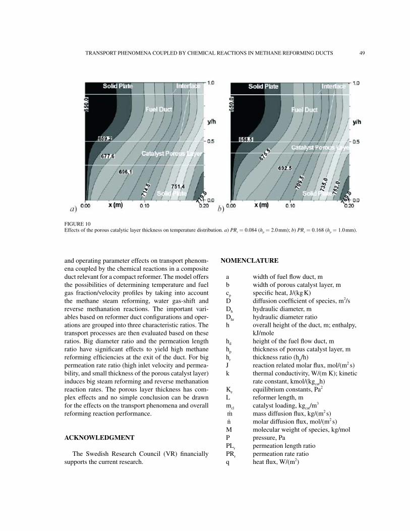
Figure 10 shows the temperature distribution to reveal the porous layer thickness effects. It is found
FIGuRe 9effects of the thickness of the porous reforming layer on distribution of steam reforming reaction rate. a) PRr = 0.084 (hp = 2.0 mm); b) PRr = 0.168 (hp = 1.0 mm).
that the reforming ducts employing thin porous layers have high temperatures in both the fuel flow duct and the porous catalyst layers. For instance, the maximum temperatures appearing in the active plate corner (the bottom plate in Fig. 1) at the exit are 779oC and 769oC for thin porous layers, compared to 758.6oC for the base condition (not shown). It is so because the thin porous catalytic layers are employed to have reform-ing reactions, where the less heat is consumed.
As discussed above, it is clear that the thickness of the porous catalytic layer has various roles in the chemical reaction rates and the transport processes. It is due to the fact that the thickness of the porous cata-lyst layer is involved in both the diameter ratio and permeation rate ratio, i.e., a thin porous layer gener-ates a smaller diameter ratio Dhr, however a bigger permeation rate ratio. Further study is needed to find an optimal thickness of the porous catalytic layer, in conjunction with the catalyst loading and distribu-tion.
CONClUsIONs
In this paper, a fully three-dimensional calculation method has been further developed to study the design
TRANSPORT PHeNOMeNA COuPLeD BY CHeMICAL ReACTIONS IN MeTHANe ReFORMING DuCTS 49
FIGuRe 10effects of the porous catalytic layer thickness on temperature distribution. a) PRr = 0.084 (hp = 2.0 mm); b) PRr = 0.168 (hp = 1.0 mm).
and operating parameter effects on transport phenom-ena coupled by the chemical reactions in a composite duct relevant for a compact reformer. The model offers the possibilities of determining temperature and fuel gas fraction/velocity profiles by taking into account the methane steam reforming, water gas-shift and reverse methanation reactions. The important vari-ables based on reformer duct configurations and oper-ations are grouped into three characteristic ratios. The transport processes are then evaluated based on these ratios. Big diameter ratio and the permeation length ratio have significant effects to yield high methane reforming efficiencies at the exit of the duct. For big permeation rate ratio (high inlet velocity and permea-bility, and small thickness of the porous catalyst layer) induces big steam reforming and reverse methanation reaction rates. The porous layer thickness has com-plex effects and no simple conclusion can be drawn for the effects on the transport phenomena and overall reforming reaction performance.
aCkNOwleDgMeNT
The Swedish Research Council (VR) financially supports the current research.
NOMeNClaTURe
a width of fuel flow duct, mb width of porous catalyst layer, mcp specific heat, J/(kg K) D diffusion coefficient of species, m2/sDh hydraulic diameter, mDhr hydraulic diameter ratioh overall height of the duct, m; enthalpy,
kJ/mole hd height of the fuel flow duct, mhp thickness of porous catalyst layer, mhr thickness ratio (hp/h)J reaction related molar flux, mol/(m2 s)k thermal conductivity, W/(m K); kinetic
rate constant, kmol/(kgcath)Ke equilibrium constants, Pa2
L reformer length, mmcl catalyst loading, kgcat/m
3
m mass diffusion flux, kg/(m2 s)n molar diffusion flux, mol/(m2 s)M molecular weight of species, kg/molP pressure, PaPLr permeation length ratioPRr permeation rate ratioq heat flux, W/(m2)

50 J. YuAN et al.
R reaction rate, kmol/(m3 s) ℜ gas constant, kJ/(mol K)re effective radius, mRe Reynolds number (uDh/ν)S source term T temperature, oCV velocity vector, m/sVi velocity components in x, y and z
directions, respectively, m/sx, y, z Cartesian coordinatesX molar fraction of fuel speciesY mass fraction of fuel species
greek symbols
β permeability of porous layer, m2
ε porosityµ dynamic viscosity, kg/(m s)ν kinematic viscosity, m2/sρ density, kg/m3
τ tortuosity
superscripts
+ forward reaction- reverse reaction
subscripts
di diffusioneff effective parameterf fuel gas mixtureform formationgm fuel gas mixture CH4 methaneCO carbon monoxideCO2 carbon dioxideH2 hydrogenH2O water in inletk Knudsen diffusionm mass transferp permeation
r steam reforming reactionre reverse methanation reaction s solid wall; shift reaction
RefeReNCes
Hoang, D.L. and Chan, S.H. (2004) Modeling of a Catalytic Auto-thermal Methane Reformer for Fuel Cell Applications, Applied Catalysis A: General 268, 207–216.
Samanta, I., Shah, R.K. and Wagner, A. (2004) Fuel Processing for Fuel Cell Application, Fuelcell2004–1515, in: R.K. Shah and S.G., Kandlikar (eds.), Proceedings of Fuel Cell Science, engi-neering and Technology, ASMe, New York.
Farrauto, R., Hwang, S., Shore, L., Ruettinger, W., Lampert, J., Gir-oux, T., Liu, Y. and Ilinich, O. (2003) New Material Needs for Hydrocarbon Fuel Processing: Generating Hydrogen for the PeM Fuel Cell, Annual Review of Material Research 33, 1–27.
Dicks, A.L., Goulding, P., Jones, S.L., Judd, R. and Ponton, K. (2001) Assessment of Advanced Catalyst Performance and Fab-rication Options for a Compact Steam Reformer, eTSu F/02/00180/ReP, DTI PuB uRN 01/1163, uK.
Zanfir, M. and Gavriilidis, A. (2003) Catalytic Combustion Assisted Methane Steam Reforming in a Catalytic Plate Reactor, Chemi-cal Engineering Science 58, 3947–3960.
Kirillov, V.A., Kuzin, N.A., Kulikov, A.V., Fadeev, S.I., Shigarov, A.B. and Sobyanin, V.A. (2003) Thermally Coupled Catalytic Reactor for Steam Reforming of Methane and Liquid Hydrocar-bons: experiment and Mathematical Modeling, Theoretical Foundations of Chemical Engineering 37, 276–284.
Yuan, J., Ren F. and Sundén, B. (2007) Analysis of Chemical Reac-tion Coupled Mass and Heat Transport Phenomena in a Meth-ane Reformer Duct for PeMFCs, Int. J. Heat Mass Transfer, 50, 687–701.
Yuan, J. and Sundén, B. (2004) A Numerical Investigation of Heat Transfer and Gas Flow in Proton exchange Membrane Fuel Cell Ducts by a Generalized extended Darcy Model, International Journal of Green Energy 1, 47–63.
Yuan, J., Rokni, M. and Sundén, B. (2003) Three-Dimensional Computational Analysis of Gas and Heat Transport Phenomena in Ducts Relevant for Anode-Supported Solid Oxide Fuel Cells, International Journal of Heat and Mass Transfer 46, 809–821.
Ferguson, J.R., Fiard, J.M. and Herbin, R. (1996) Three-dimen-sional Numerical Simulation for Various Geometries of Solid Oxide Fuel Cells, Journal of Power Sources 58, 109–122.
Ackmann, T., Haart, L.G.J., Lehnert, W. and Thom, F. (2000) Mod-elling of Mass and Heat Transport in Thick-Substrate Thin-electrolyte Layer SOFCs, in: Proc. 4th european Solid Oxide Fuel Cell Forum, Lucerne /Switzerland, 431–438.