Embed Size (px)
Citation preview
Transportat ion and Disposal Planfor the
American Creosote Works ProjectFormerly known as
American Creosote Works-Winnf i e ld PlantW i n n f i e l d , Louisiana
rPrepared for:
rEPA Region VI
Prepared by:CH2M H I L L
7600 W. Tidwe l l Rd., Suite 400Houston, Texas 77040-5719
J u l y 12,1999
002181
ContentsSection Page1. Introduction.............................................".•.......................................•..•..•..............•.........I1.1 S i t e History and Background.................................................................................... 12. Waste Handl ing and Packaging....................................................................................... 3
2.1 Waste P r o f i l e and Quantity Estimates.......................................................................32.2 Waste Handl ing and Packaging.................................................................................62.3 Accident Prevention................................................................................................ 11
3. Sampl ing and Analysis Plan........................................................................................... 133.1 S a m p l i n g Procedures............................................................................................... 133.2 S a m p l e Identification.............................................................................................. 143.3 S a m p l e Documentation........................................................................................... 143.4 S a m p l e Custody....................................................................................................... 153.5 S a m p l e Packaging and Shipment............................................................................ 15
4. Quality Assurance/Quality Control Procedures—.—...—..—................................... 184.1 Data Quality Objectives.......................................................................................... 184.2 Equipment Decontamination Procedures................................................................ 184.3 Analytical Program..................................................................................................18
Table s2-1 Waste Types/Storage/Quantities.........................................................................................42-2 Creosote (NAPL) Laboratory Analys i s Results..................................................................52-3 TSD Fac i l i ty Information..................................................................................................11
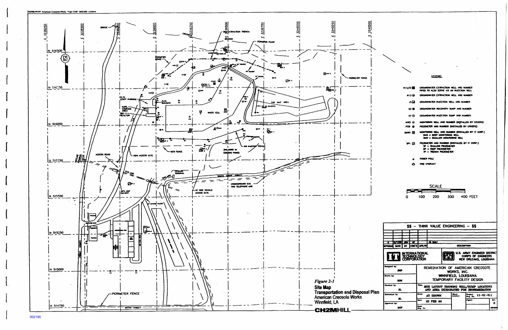
Figures1-1 Vicinity Map.......................................................................................................................22-1 S i t e Map..............................................................................................................................8
CH343.DOCCVO991730002
002182
1. I n t r o d u c t i o nT h i s Transportat ion and Disposal Plan (TDP) describes the f a c i l i t i e s and procedures for the handling,labeling, packaging and o f f s i t e transportation of waste materials generated from operation of theAmerican Creosote process liquid treatment system (PLTS) located in W i n n f i e l d , Louisiana. T h i sdocument was prepared in accordance with the requirements of EPA WA No. 035-RARA-063G,SOW Task 3, Item 3.4 (EPA, March 16, 1999). The original version of this plan was prepared by theI T - G r o u p in accordance with the U.S. Army Corps of Engineers (USAGE) Contract S p e c i f i c a t i o n(CS) Section 02090-OFFS1TE TRANSPORTATION AND DISPOSAL and the Waste H a n d l i n g andPackaging Plan.T h i s plan also describes the sampling and analytical programs necessary to select the proper methodfor o f f s i t e waste disposal. Additional information regarding s p e c i f i c sampling and analyticalprocedures is contained in the Quality Assurance Project Plan (QAPP) portion of this document andthe Process Liquid Treatment System (PLTS) modif ied version of the O&M Manual.
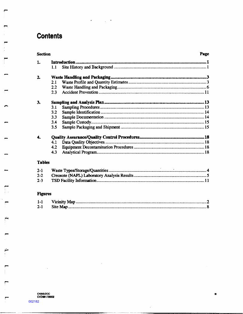
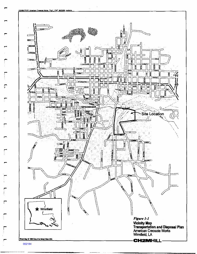
1.1 Site History and BackgroundThe American Creosote Works Super fund Site is located in the southern portion of W i n n f i e l d ,Louisiana, in Winn Parish (see Figure 1-1), approximately 80 miles southeast of Shreveport,Louisiana. The site is approximately 34 acres in size and bounded by Wat t s Street to the south, GroveStreet to the east, Kansas City Southern Railroad to the North and Front Street to the west. Theadjacent properties are mostly residential with some abandoned industrial areas nearby.The earliest records of the site date back to 1901 when it was developed to treat wood using creosoteand pentachlorophenol (PCP). In 1983, in response to a release of uncontrolled contamination, theLouisiana Department of Environmental Quality (LDEQ) issued a letter of warning to S t a l l w o r t hTimber Company. In 1985 Stal lwor th Timber Company abandoned the site subsequent to acompliance order issued by the LDEQ. The LDEQ referred the site to the U.S. EnvironmentalProtection Agency (EPA) for action. In 1989, the EPA Emergency Response Branch conductedsource control and contaminant migration control actions. In 1994, the EPA awarded a contract to ITCorporation to implement cleanup actions at the site. These actions consisted of excavation and onsiteincineration of contaminated soil and s ludge, and in-situ bio-remediation of deep subsurfacecontamination.The bio-remediation component of the projec t scope included installation of extraction and injectiontrenches and wells, design and construction of a Process Liquids Treatment Syst em (PLTS), and a 3-year operations and maintenance program. The PLTS is designed to separate creosote recovered fromthe groundwater extraction well and trench array, and to treat groundwater to remove dissolve phasecreosote constituents to a level that allows re-injection or discharge to a nearby surface drainage.Prior to re-injection, treated groundwater is amended with oxygen and nutrients to stimulate in-situbiological activity.Recovered creosote (NAPL) is currently transported o f f s i t e for incineration, but was incineratedonsite with contaminated soil and sludge earlier in the projec t .
CH343.DOCCVOW91730OB002183
152496.PP.PP American CreMOte Vtorks T«1 1.fhB' 06/22/99 cvo/arrw
i f W i n n f i e l d} (———I
Sire* Map C1996 DtLomw Street ASw USA
1-1Vicinity MapTransportat ion and Disposal PlanAmerican Creosote WorksWinnfield, LAC H 2 I W I H I L L — — — — — — —
002184
2. Waste Handling and Packag ingT h i s section contains information and procedures required to:• I d e n t i f y the type and quantity of waste generated from operation of the PLTS and other activities
during routine site operations and maintenance.• Characterize the waste in terms of contaminant concentrations, hazard ident i f i ca t ion, and
assignment of the proper RCRA Waste Code.• S p e c i f y proper handling and packaging procedures required for onsite storage, sampling,
handling and transfer of wastes for d i spo sa l .• I d e n t i f y the TSD F a c i l i t y (TSDF), transportation method and equipment, description of TSD
treatment and disposal process.• Provide a list of permits, licenses and other authorizations held by the TSDF, date of last RCRA
inspection, record of any active compliance orders, and information regarding costing proceduresat f a c i l i t y , provided the current TSDF is changed.
• Discuss accident prevention in the handling, transportation storage and disposal of AmericanCreosote wastes.• Provide Analytical Cert i f i ca t e s for chemical analysis of wastes, additional data and information
from TSDF, and examples of the waste manife s t ing program to be used.
2.1 Waste Profile and Quanti ty EstimatesThe PLTS process generates several types of wastes, all associated with the primary waste stream ofRecovered NAPL. The description of the waste and the estimated quantity and frequency, as well asstorage detail s are listed below in Tabl e 2-1.Waste T y p e No. 1 (recovered NAPL) was sampled by IT Corporation on August 15,1997. Thelaboratory analysis revealed the presence of volatile, semivolatile and trace metal constituents asshown in Tabl e 2-2. Based on this analysis, a waste characterization was performed by FTC o r p o r a t i o n ' s Knoxv i l l e Laboratory. The results of the analysis and a Waste Material Data Sheet areprovided as A p p e n d i x A & B of IT's original O f f s i t e Transportation and Disposal Plan, dated October22,1997. T h i s document i s on f i l e in CH2M HILL's Houston o f f i c e .The RCRA Waste Code most appropriate for Waste T y p e No. 1 (recovered NAPL) generated by theAmerican C r e o s o t e ' s PLTS is U051. T h i s code was suggested in the original EPA documentationprovided in the ROD regarding the recovered product. ENSCO's TSDF personnel at the Dalton, GA.and El Dorado, AR. locations reviewed the work done by IT Corporation.
CH343.DOCCVOW91730002002185
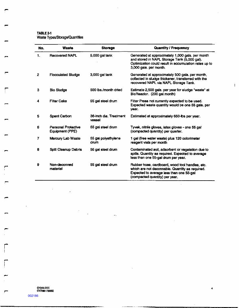
TABLE 2-1Waste Types/Storage/Quant i t i e sNo. Waste Storage Quantity / Frequency
1. Recovered NAPL
3 Bio S l u d g e4 Filter Cake
5 Spent Carbon6 Personal ProtectiveEquipment ( P P E )7 Mercury Lab Waste
9 Non-deconnedmaterial
5,000 gal tank
Floc cu la t ed S l u d g e 3,000 gal tank
500 I b s V m o n t h dried55 gal steel drum
36-inch dia. Treatmentvessel55 gal steel drum55 gal po lye thylenedrum
Spill C l e a n u p Debris 55 gal steel drum
55 gal steel drum
Generated at approx imat e ly 1,000 gals , per monthand stored in NAPL Storage T a n k (5,000 gal).Optimization could result in accumulation rates up to3,000 gal s , per month.Generated at a p p r o x i m a t e l y 500 gal s , per month,collected in s ludge thickener, transferred with therecovered NAPL via NAPL Storage Tank.Estimate 2,500 gals , per year for s l u d g e "waste" atBioReactor. (200 ga l .month)Filter Press not currently expected to be used.Expected waste quantity would be one 55 gal s , peryear.Estimated at approx imate ly 650-lbs per year.Tyvek, nitrite gloves, latex gloves - one 55 gal(compacted quantity) per quarter.1 gal (free water waste) p l u s 120 colorimeterreagent vials per monthContaminated soil , adsorbent or vegetation due tos p i l l s . Quantity as required. Expected to averageless than one 55-gal drum per year.Rubber hose, cardboard, wood tool handles, etc.which are not deconnable. Quantity as required.Expected to average less than one 55-gal(compacted quanti ty) per year.
CH343.00CCVO991730002002186
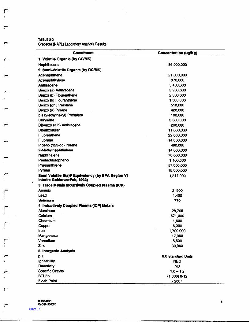
TABLE 2-2Creosote (NAPL) Laboratory Analys i s ResultsConstituent Concentration ( u g / K g )
rr
1. Volatile Organic (by GC/MS)N a p h t h a l e n e2. Semi-Vola t i l e Organic (by GC/MS)AcenaphtheneAcenaphthyl eneAnthraceneBenzo (a) AnthraceneBenzo (b) Flouran th eneBenzo (k) FlourantheneBenzo (ghi) PeryleneBenzo (a) Pyrenebis ( 2 - e t h y l h e x y l ) Phtha la t eChryseneDibenzo (a,h) AnthraceneDibenzofuranFluorantheneF l u o r e n eIndeno (123-cd) Pyrene2-Methylnaph tha l eneN a p h t h a l e n ePentachlorophenolPhenanthrenePyreneSemi Vola t i l e B(a)P Equivalency (by EPA Region VIInterim Guldance-Feb, 1992)3. Trace Metal s Inductively Coupled Plasma (ICP)ArsenicLeadSelenium4. Induc t ive ly Coupled Plasma (ICP) Metal sA l u m i n u mCalciumChromiumCopperI r o nManganeseVanadiumZinc5. Inorganic Analysi sPHI g n i t a b i l i t yReactivitySpec i f i c GravityB T U / l b .Flash Point
86,000,00021,000,000
970,0005,400,0003,900,0002,300,000I,300,000510,000420,000100,000
3,800,000260,000
II,000,00022,000,00014,000,000
490,00014,000,00070,000,0001,100,000
57,000,00015,000,0001,517,000
2,9001,400770
28,700571,000
1,6006,300
1,700,00017,0006,800
39,3008.0 Standard Units
N E GN D1.0-1.2
(1,000)8-12>200F
rCH343.DOCCVO\9917300Q2
002187
The remaining waste types were not tested or characterized indep enden t ly because they are associatedwith the breakdown and treatment of the recovered NAPL. Unless there is a s ignif i cant visual changein the phys i ca l/chemical characteristics of this material, Waste T y p e s 2 through 6, 8 and 9 will beassigned the same characterization and waste code as T y p e 1 (U051). Waste T y p e 7 (mercury labwaste) will be coded separately. EPA will be advised in advance of any planned wastecharacterization testing.
2.2 Waste Handling and PackagingThere are four waste types recovered from operation of the PLTS, ident i f i ed in T a b l e 2-1 as Was t eT y p e Nos . 1 through 4. The remaining wastes are materials that have become contaminated through
_ the testing, handling or accidental s p i l l a g e of Waste T y p e Nos. 1 to 4.2.2.1 Waste Handling and Packaging: Current Practices (offsite incinerat ion)
r~ Waste accumulated from PLTS operation and other site activities will require o f f s i t e transportationand disposal to an approved TSDF. Each of the three available TSDF's proposed later in this planprovide transportation and disposal services for each generated waste type. CH2M HILL has* reevaluated these f a c i l i t i e s for use as a TSDF to ensure EPA is getting a competitive service.Recovered NAPL and Flocculated S l u d g e from the S l u d g e Thickener will be stored in the NAPLStorage Tank and transferred via pump AP-3 through the PLTS building west wall to a f l anged outlet
*"" in the Oil T r a n s f e r area. When the NAPL Storage Tank high level set point (80% f u l l and 4,000gal lons) is reached, a waste pickup and di sposal will be scheduled. The contents of the NAPL StorageTank will be pumped directly into a transport tanker suppl i ed by the TSDF. The volume/weight ofr~ waste will be measured using the f a c i l i t y scale and recorded on the NAPL Trans f e r Log by thedesignated PLTS Operator and on the Hazardous Waste Manif e s t by the TSDF driver.
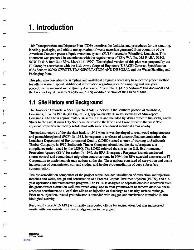
,_ Spill Cleanup material, Combustible Debris and PPE will be placed in DOT approved, 55-gallon' drums. The drums will be stored onsite, hi the hazardous waste storage area. The primary location forstorage of f i l l e d 55-gallon drums is the south end of the Oil Trans f er S l a b , which will hold up to sixdrums (see Figure 2-1). Drums containing non-liquid wastes will be placed in the PLTS Building
*"" under the f i l t e r press stand. Activated s ludge bio-solids will be either dewatered hi a plate and framef i l t e r press or newly constructed drying bed. The dewatered sol ids will be placed in 55 gallon drumsand transported to an o f f s i t e l a n d f i l l .Mercury lab waste will be placed in a separate 55-gallon drum, stored in the PLTS Building near theOil water Separator. All drummed wastes will be weighed by the TSDF driver or f a c i l i t y and the
_ quantity recorded on the Hazardous Waste Manif e s t .I Storage of contaminated wastes shall not exceed the 90-day accumulation tune spec i f i ed in T i t l e 40Code of Federal Regulations (CFR) Part 262 for temporary storage. The time of accumulation shallf~ begin when contaminated wastes are f ir s t placed into storage containers, or in the case of spent! carbon, when it is removed from service.
r A p p l i c a b l e Packaging Management S t a n d a r d sTwo forms of packaging will be utilized at the site, containers for storing those wastes that do notcontain free l iquids, and tanks for liquids and other wastes containing free liquids.
CH343.DOCp. CV0091730002002188
r
Container Management S t a n d a r d sContainers used to store non-liquid bearing waste materials will include 55 gallon drums. Containerswill be stored at a secure location with a f irm foundation in accordance with 40 CFR 264 Subpart I.The current practice is to store this material inside the PLTS building. T h i s storage area does notrequire secondary containment provided the f o l l o w i n g standards are met at all times:• Stored materials do not contain free l iquids• Containers are in good structural condition (no holes, leaks, or excessive rust) and compatible
with the stored waste• Containers are inspected weekly for sound structural condition• Containers must be kept closed unless waste is being added or removed• Containers must be handled to avoid ruptures or leaks.Containers storing hazardous waste for less than 90 days will be marked with the words "HazardousWaste" and with an "accumulation date", which is the date waste was first placed in the container [40CFR 262. (a) (2),(3)]. Containers will also be marked to indicate the waste source and containercontents.
CH343.DOCCVO991730002002189
5* filiiii
ii a • i !i
002190
Tank Management S t a n d a r d sTanks used to store hazardous material will be managed in accordance with 40 CFR 264 Subpart J.All tanks will be located within the PLTS enclosure. The s e tanks will also be managed according tothe f o l l o w i n g standards:1. Inspec t ed on a dai ly basis2. Located within a secondary containment system capable of containing leaks and s p i l l s within a
24-hour period to prevent contamination of the surrounding environment.3. Storage tanks will also be labeled with the words "Hazardous Waste" in accordance with 40 CFR
262.34(a)(3) and will be i d en t i f i ed with a unique tag number.Contaminated S o i l s PackagingContaminated soils derived from s p i l l cleanup around extraction wells will be placed in DOTapproved 55-gallon drums. Once a drum becomes f u l l it will be sealed and a unique ident i f i er a f f i x e dto the drum using black indelible ink. The ident i f i er will begin with the extraction well numberf o l l o w e d by the month, day and year, as shown in the f o l l o w i n g example:
Drum Label = R4-09-02-99This label corresponds to contaminated soil obtained from cleanup around recovery well R4 onSeptember 09,1999. The drum shall also be marked to indicate the contents. Once sealed, the drumswill be relocated to the hazardous waste storage area. Drums will be removed from the site at amaximum interval of 90 days.Recovered NAPL StorageOil and NAPL recovered by the oil/water separator will be pumped to a vented, closed-top storagetank located within the PLTS building. T h i s tank has a maximum capacity of 5,000 gallons and isconstructed of lined, carbon steel. A 1 Va-inch transfer outlet is located at the bottom of the tank toallow for pumping to a transport truck. It is anticipated that the recovered NAPL will be removedfrom the site every 1 to 3 months.S p e n t Carbon MediaWhen carbon media is spent it will be retained in the treatment vessel and pumped directly to thes u p p l i e r ' s truck.Sludge StorageS l u d g e generated by the oil/water separator and lamella clarif ier may be dewatered using a p la t e andframe f i l t e r press. If dewatering is performed, water from the press will be pumped to the equalizationtank for treatment. Dewatered sludge will be placed in a 55 gallon drum. Currently, the press is not inuse.Personal Protective Equipment PackagingPersonal Protective Equipment (PPE) required for the operation and maintenance of the PLTS will bebagged and placed into drums. Each drum will be marked with an ident i f i er using black indelible ink.The ident i f i er shall begin with "PPE" f o l l o w e d by the month, day and year on which the f ir s t contentswere placed in it (i.e., PPE-MO-DA-YR). Drums will be removed from the site at 90-day intervals.Approx imate ly three drums will be removed at 90-day intervals.
CH343.0OCCVO991730002002191
2.2.2 DocumentationA Waste Packaging Log will be f i l e d for each container temporarily stored at the site prior to o f f s i t edi sposal. A copy of the log will be placed in the permanent projec t records.The f o l l o w i n g information is required on the Waste Packaging Log, as appropriate:1. Projec t name and number2. Date prepared3. P r e p a r e r ' s name4. Container ident i f i er5. Date of initial waste placement6. Date of f inal waste placement7. S a m p l e I.D., Chain-of-Custody, Request for Analys i s Form numbers8. Approximate quantity9. Observations of c o n t a i n e r ' s structural integrity10. Date of o f f - s i t e disposal Name of waste hauler11. Name of di sposal f a c i l i t y .2.2.3 Waste Transpor ta t i onThe TSDF providing o f f s i t e disposal services will also provide for transportation of PLTS waste fromthe American Creosote site to their fa c i l i ty . The PLTS will generate mostly liquid and s ludge wastes,which will be transported by tanker truck. Other solid waste generated at the PLTS will becontainerized in 55-gallon drums and transported by a separate truck.Transpor ta t i on Vehic le sThe transport tankers used for liquid and sludge wastes will be MC 312/307, rated at 35-psig. Alltanks have external support rings and are constructed of type 304 stainless steel. Each tanker isexpected to carry approximately 70 feet of 2" and 3" hose, with bottom mounted vacuum pumps withscrubbers. Liquids will pass through a 20-mesh screen at pressure no greater than IS-psig duringloading or unloading. All transport tankers will be DOT approved for RCRA/CERCLA wastetransportation.Box trucks will be used for solid wastes (considered LTL or less than truckload), either in drums orother DOT approved shipping containers. These vehicles will be equipped with secondarycontainment f l oor s , load locks, and spi l l kits. The onboard sp i l l kit will include two 85-gallon over-pack drums, absorbents, shovel, tape, p las t i c sheeting, drum plug s and silicone sealant. All solidstransport vehicles will be DOT approved for RCRA/CERCLA waste transportation.Transport drivers will be f u l l y trained and equipped with s u f f i c i e n t s a f e t y equipment to respond toincidents. Equipment includes PPE, rubber boots and gloves, hard hats, face shields and sa f e tyglasses, f l a s h l i g h t s and re f l ec tors , f ire extinguishers and emergency response instruction guide. TheTSDF will also carry insurance coverage, which exceeds that required by 40 CFR §264.147, SubpartH of $1,000,000 automobile l i ab i l i ty , $25,000,000 excess l iab i l i ty , and $10,000,000 po l lu t i onliabil i ty.Transporta t ion RouteCurrently, the f o l l o w i n g procedure is used at the site. T h i s process/procedure may change once all ofEPA's options for disposal are considered. However for now, this process seems to work well.A f t e r loading of the transport vehicle, any visible contamination on the transport vehicle is removedbefore the driver leaves the PLTS plant area using the pressure washer located at the decontamination
CH343.DOC 10CVCA991730002002192
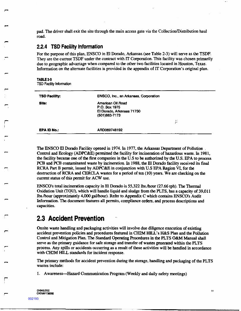
pad. The driver shall exit the site through the main access gate via the Co l l e c t i on/Dis t r i bu t i on haulroad.2.2.4 TSD Facil i ty Informat i onFor the purpose of this p lan, E N S C O in El Dorado, Arkansas (see Tabl e 2-3) will serve as the TSDF.
•""" T h e y are the current TSDF under the contract with IT Corporation. T h i s f a c i l i t y was chosen primarilydue to geographic advantage when compared to the other two f a c i l i t i e s located in Houston, Texas .Informat ion on the alternate f a c i l i t i e s is provided in the appendix of FT C o r p o r a t i o n ' s original plan.TABLE 2-3T S D F a c i l i t y I n f o r m a t i o n
TSD F a c i l i t y : ENSCO, Inc. , an Arkansas, CorporationSite: American Oil RoadP.O. Box1975El Dorado, Arkansas 71730(501)863-7173r 'PERA ID No.: ARD069748192
The E N S C O El Dorado Fac i l i ty opened in 1974. In 1977, the Arkansas Department of PollutionControl and Ecology ( A D P C & E ) permitted the f a c i l i t y for incineration of hazardous waste. In 1981,the f a c i l i ty became one of the f irst companies in the U.S to be authorized by the U.S. EPA to processPCS and PCB contaminated waste by incineration. In 1988, the El Dorado f a c i l i t y received its finalRCRA Part B permit, issued by ADPC&E in conjunction with U.S EPA Region VI, for thedestruction of RCRA and CERCLA wastes for a period of ten (10) years. We are checking on thecurrent status of this permit for ACW use.ENSCO's total incineration capacity in El Dorado is 55,322 I b s T h o u r (27.66 tph). The ThermalOxidation Unit (TOU), which will handle liquid and sludge from the PLTS, has a capacity of 39,011lbs./hour (approximately 4,000 gal/hour). Refer to Appendix C which contains ENSCO's AuditInformation. The document features all permits, compliance orders, and process descriptions andcapacities.
2.3 Accident PreventionOnsite waste handling and packaging activities will involve due diligence execution of existingaccident prevention policies and procedures featured in CH2M HILL's H&S Plan and the PollutionControl and Mitigation Plan. The Standard Operating Procedures in the PLTS O&M Manual shallserve as the primary guidance for sa f e storage and transfer of wastes generated within the PLTSprocess. Any s p i l l s or accidents occurring as a result of these activities will be handled in accordancewith CH2M HILT, standards for incident response.The primary methods for accident prevention during the storage, handling and packaging of the PLTSwastes include:1. Awareness—Hazard Communication Program (Weekly and daily s a f e t y meetings)
CH343.DOCCVO\991730002002193
2. Training—Famil iar iza t i on with procedures and guidelines for waste handling activities (PLTSStandard Operating Procedures contained in O & M Plan)
3. I n s p e c t i o n s — T h e PLTS O&M manual requires inspection of transfer and storage equipment.Preventive maintenance will also he lp reduce equipment leaks or fa i lure s .
4. Response P l a n — T h e Response Plan de f ine s roles and responsibi l i t i e s , emergency contacts,emergency procedures, and f o l l o w - u p strategies.Spill containment equipment is maintained at the PLTS for response actions. These items includeabsorbent pads, granular absorbent material, polyethylene sheeting, S S - g a l l o n drums, shovels, andassorted hand tools.A f t e r the wastes are transferred to the TSDFs transport vehicle, the Accident Prevention Policies ofthe TSDF and applicable DOT regulations shall govern.
CH343.DOC 12CVOHM1730002002194
3. Sampling and A n a l y s i s PlanProper sampling and analysis of PLTS wastes and other wastes generated over the course of the sitecleanup is necessary to ensure that each waste receives its proper waste c la s s i f i ca t i on code, and ishandled and disposed in accordance with regulatory requirements.As indicated in Section 2.1 (Waste P r o f i l e and Quantity Estimate), creosote recovered from theextraction wel l s/ trenches has been tested and characterized with a U051 waste code. Many of theother wastes generated onsite have become contaminated with creosote as a result of treatingextracted groundwater. Consequently, routine sampl ing and analysis of wastes produced fromoperation of the PLTS is not expected. However, in the event a new waste stream is generated, or thecharacteristics of an existing waste stream change markedly, sampling and analysis will be performedto ensure proper waste c la s s i f i cat ion and disposal. Procedures for sampling and analysis of PLTSwaste streams are presented in the f o l l o w i n g subsections. Additional information regarding theS a m p l i n g and Analys i s Program is contained in Section 4.0, Quality Assurance/Quality Control Plan.
3.1 Sampling ProceduresThe f o l l o w i n g subsection outlines the procedures to be used for sampling waste streams associatedwith routine operation of the PLTS, or waste streams that may be encountered at the site during dailyoperations. All sampling will be conducted in compliance with the protocols established bypublications EPA-600/2-80-01 8, S a m p l i n g Procedures for Hazardous Waste Streams, and EPA-600/4-84-043, Soil Sampl ing Quality Assurance User's Guide.3.1.1 Recovered NAPL Sampling (Waste Type No. 1)Prior to sampling, the level of recovered oil/NAPL in the tank will be recorded to determine thevolume. A sample(s) will be obtained from a sample port located on the 114-inch transfer valve at thetank bottom. The sample port will in i t ia l ly be opened to f l u s h standing oil in the line, and the contentscollected in a bucket. S a m p l e s will then be obtained and collected directly into the appropriatecontainer(s). Excess oil/NAPL will then be returned to the tank.3.1.2 Bio-Sludge S a m p l i n g (Waste Type Nos. 2,3 and 4)S l u d g e samples will be obtained at a minimum of four locations within each of the bioreactorcompartments from which sludge will be discharged.. These samples will then be composited toobtain a representative sample. Excess materials will be returned to the bioreactor. S a m p l i n g will beperformed using a stainless steel scoop and bucket.3.1.3 Spent Carbon Media S a m p l i n g (Waste Type No. 5)No samples of spent carbon media will be obtained.3.1.4 Personnel Protective Equipment S a m p l i n g (Waste Type No. 6)
No samples will be obtained from PPE.
CH343.DOC 13CVOW91730M2002195
3.1.5 Contaminated Soil Sampling (Waste Type No. 8)Contaminated soil generated from spill cleanup will be collected using decontaminated stainless steeltrowels or spoons. Representative material from several locations within the s p i l l area will becollected and composited in a stainless steel bowl and then placed into the appropriate samplecontainer.
3.2 S a m p l e IdentificationTo prevent mi s ident i f i ca t ion of samples, legible labels will be a f f i x e d to each sample container withs u f f i c i e n t information to uniquely i d e n t i f y the sample in the absence of other documentation. Thelabels will contain the f o l l o w i n g information:
Project name and numberUnique sample numberS a m p l e locationName or init ial s of collectorDate and time of collectionPreservation method employedAnalys i s required (if space on label allows).
The sample labels will always be directly a f f i x e d to the sample container and will always becompleted using black indelible ink. S a m p l e s will be assigned a unique ident i f i er that documents thesample location and the round of sampling. The f ir s t part of the sample identi f ier will designate thesample location:RON = Recovered OuVNAPLSL = S l u d g e (oil/water separator, lamella or biosol ids)R4SC = spill cleanup material (absorbent, soil) from recovery well 4.The next part of the sample identi f i cat ion will designate the sampling sequence by month, day, andyear when the sample was collected and, if more than one sample is collected for that date, thenumerical order of the sample. If there is not a third part of the sample identi f ier, the sample is notpart of a sequence. The "dash" in the sample ID is part of the ident i f i er and will be used when writingthe label and f i l l i n g out the forms.The f o l l o w i n g is an example of a sample identifier:• SL-09-23-97 - A sludge sample collected on September 23,1997Fie ld dupl i cate samples will be ident i f i ed in a similar way as regular samples. The analyticallaboratory will not know which samples are duplicates .
3.3 S a m p l e DocumentationA sample collection log will be f i l l e d out for each collected sample and will be placed in thepermanent projec t records. A sample collection log will be prepared for each sample to recordinformation pertaining to the location, condition, and collection of a sample. The f o l l o w i n ginformation is required on the sample collection log, as appropriate:• Project name and number
CH343.DOC 14CVCM91730002002196
Date and time of sample collectionS a m p l e collection team membersSample ident i f i cat ion number, location, and sample matrixWeather conditionsNumber and type of sample containersQuantity of sample co l l ec tedPreservation method employedS a m p l e observations
S a m p l e collection logs will be signed and dated by the sample collector. S a m p l e collection logs willbe kept in the permanent projec t record to document collection of samples.
3.4 S a m p l e CustodyA CH2M HILL Chain-of-Custody (COC) form will be used to document custody for all samples.T h i s record will accompany the sample at all times, from f i e l d to laboratory, and will be placed in theproje c t f i l e a f t er sample disposition. For these procedures, a sample is considered to be in custody if itis:• In one' s actual possession• In view, af t er being in physical possession• Locked so that no one can tamper with it, a f t er having been in physical possession• In a secure area, restricted to authorized personnel.
3.5 S a m p l e Packaging and S h i p m e n tEach individual who has the samples in his or her possession will sign the COC form. F i e l dpreparation of this record shall be as f o l l o w s :• The COC will be initiated in the f i e l d by the person collecting the sample. Every sample will be
assigned a unique ident i f i ca t ion number that is entered on the record. Sample s can be grouped forshipment using a single record.
• The form will indicate the project name, sampling team, laboratory destination, specialinstructions, and possible sample hazards.
• If the person collecting the sample does not transport the samples to the laboratory or deliver thesample containers for shipment, the f ir s t block for Relinquished By _, Received By _, will becompleted in the f i e l d .
• The personnel transporting the samples to the laboratory or delivering them for shipment shallsign the record as Relinquished By _.
• If the samples are shipped to the laboratory by commercial carrier, the original COC and RFARecords will be sealed in a watertight container and placed in the shipping container. Thes h ipp ing container will be sealed prior to being given to the carrier. A copy of the forms will bekept in the project f i l e s .
• If the samples are transported direct ly to the laboratory, the COC and RFA Records will be keptin possession of the person delivering the samples.
CH343.DOC 15CVO981730002002197
• For samples shipped by commercial carrier, the waybill will serve as an extension of the recordbetween the f inal f i e l d custodian and receipt in the laboratory.
As each sample is collected in the f i e l d , it will be placed in labeled bott le s and stored in an icedcooler. S a m p l e preparation will include properly label ing the bottles and storing the samples on ice atapproximately 4 degree C. COC documents will be prepared in the f i e l d for all samples mat will beshipped to a laboratory.The f o l l o w i n g steps shall be taken to assure that all samples reach the laboratory in as sampledcondition: (Note for local laboratory pickup, s teps 4, 5, and 8-14 may be omitted.)1. Sample containers will be suppl i ed and prepared according to sample type. S a m p l e s which will
be shipped to the laboratory will be prepared for shipment using the f o l l o w i n g procedures (ifappropriate, according to the sample shipment containers suppl i ed by the laboratory):2. Tigh t en sample bottle l i d s hand-tight.3. Check sample label to make sure it is correct and complete.4. Place about 3 inches of packing material in the bottom of a waterproof metal or equivalent-
strength plas t ic cooler.5. Place bottles in clean pla s t i c bags in the cooler hi such a way that they do not touch.6. Glass and VOC vials should be placed hi the center of the cooler. Plastic bottles should be placed
near the inside wall of the cooler or between glass bottles.7. Put ice in p la s t i c bags and place in cooler, on and around bottles.8. Fill remaining space in cooler with packing material.9. Place the COC and RFA Records in a p la s t i c bag and attach to the inside of the cooler lid withmasking tape or duct tape.10. If the cooler has a drain, tape it shut.11. Close cooler and secure lid by taping cooler complete ly around with s trapping tape at twolocations.12. Place l a b o r a t o r y ' s address on top of cooler.13. Put "This S i d e Up" and "Fragile" labels on the cooler.14. Affix custody seals on from right and back l e f t of cooler; cover seals with side, clear tape.While awaiting packaging, samples will be stored on ice in coolers. All samples will be preserved atthe time of sample collection. At no time will samples be left out in the open or sun. If samplescannot be shipped on the same day that they would be packaged, packaging will be delayed until thef o l l o w i n g morning so that the samples can be shipped with a f u l l load of ice. Such samples will bestored on ice hi coolers and kept in a secure area. Custody of sample stored overnight is theresponsibil i ty of the sample collector or site supervisor with proper COC documentation.For remote laboratories, a f t er the samples have been packaged for shipping, the coolers will beshipped to the laboratory via overnight courier. Upon shipment of the samples, the laboratory will benoti f ied that a sample shipment is scheduled to arrive.
CH343.DOC 16CVO991730002002198
An e f f o r t will be made to provide the laboratory with a 1-week advance notice of sample shipment.S a m p l e s will not be collected on Fridays without prior laboratory approval for sample receipt onSaturdays.The S i t e Supervisor will call the laboratory on the day of sample receipt at the laboratory to check onthe condition of the samples and to confirm the data recorded on the COC.F o l l o w i n g its receipt of the samples, the laboratory will inspect and veri fy the samples and completethe COC as to the number and condition of the samples sh ipped. If samples are warm, broken, mis-labeled, or have other data that does not match the COC, the laboratory will fill out a variance form.
ri
CH343.DOC 17CVO991730002002199
4. Q u a l i t y A s s u r a n c e / Q u a l i t y ControlProceduresT h i s section br i e f ly describes the Quality Assurance/Qual i ty Control ( Q A / Q C ) procedures that will ber- implemented for sampling and analysis of wastes generated from routine operation of the PLTS.QA/QC samples will consist of blanks, dupl i ca t e s , trip blanks, matrix spike/matrix spike dupl i ca t e s(MS/MSD). Precision and accuracy will be determined using MS/MSD analysis. Contract Laboratoryr" Plan-statement of work ( C L P - S O W ) criteria will be used to evaluate precision and accuracy and dataverification. Precision and accuracy data will be used to determine completeness or percentage ofusable data points.r™4.1 Data Qual i ty Objectives
*"" The chemical data quality objective is to collect representative samples and conduct chemical analysiswith required QA/QC to ensure the data are of s u f f i c i e n t quality to make decisions. Proper wastec la s s i f i ca t ion code and o f f s i t e disposal determination is the primary data quality objective for this
""" projec t .
4.2 Equipment Decontamination ProceduresS a m p l i n g equipment including bailers, spoons, buckets, pumps, and associated equipment will bedecontaminated between sample locations either directly at the sample location or at the primary*~ decontamination area. The Site Supervisor will select the decontamination area. The decontaminationprocedure for equipment used in collection of the samples for chemical analyses will be as f o l l o w s :
*— 1. Wash sampling equipment with alconox solution and potable water.2. Rinse in potable water.3. Rinse with methanol.
,__ 4. Rinse with potable water.I 5. Rinse with d i s t i l l ed deionized water.
6. Air dry.f~ A f t e r decontamination, the sampling devices will be wrapped in aluminum fo i l shiny side out or clean
polyethylene plas t i c to prevent contamination during handling. Decontamination water will betransferred to the PLTS for treatment. For each sampling location and each event, sample teami— members will wear new, clean gloves. Gloves shall be discarded, along with other soiled PPE,I f o l l o w i n g each sampling event.
4.3 Analytical ProgramAn analytical program to characterize PLTS wastes will be developed in a manner which ensures thatit complies with the requirements of EPA publication SW-846, Test Methods for Evaluating Sol idWaste , Physical and Chemical Methods Manual. Thi s analytical program will be developed based onthe results of the Remedial Action (RA) Performance Veri f i ca t ion and RA Completeness Ver i f i ca t i onTes t ing Programs.
CH343.DOC 18CVCA9917300Q2002200
The analytical program will also address analytical requirements for the o f f - s i t e di sposal f a c i l i t i e s .Details regarding this program will be submitted as a part of the CH2M HELL QAPP.4.3.1 Analytical LaboratoriesAll laboratories performing analytical work for CH2M HILL on the American Creosote pro j e c t willadhere to the f o l l o w i n g :1. EPA publication, User's Guide to the Contract Laboratory Program (CLP) 1990.2. EPA publication, Contract Laboratory Program (CLP) Statement of Work (SOW) for Organic
Analys i s , March 1990.3. EPA publication, Contract Laboratory Program (CLP) Statement of Work for Inorganic A n a l y s i s ,
March 1990.4. EPA publication SW846, T e s t Methods for Evaluating S o l i d Waste , Physical and Chemical
Methods Manual.5. Special Clause H-6, Quality Control for S a m p l i n g and Tes t ing of Hazardous, Toxic , andRadiological Waste (HTRW).6. Special Clause H-7, Environmental Data Management and Reporting.
CH343.DOC 19CVCM81730002002201