Embed Size (px)
Citation preview

WWW.IJITECH.ORG
ISSN 2321-8665
Vol.04,Issue.17,
November-2016,
Pages:3260-3267
Copyright @ 2016 IJIT. All rights reserved.
Transportation Safety Enhancement using RFID Technology B.RASHMITHA
1, MOHAMMAD ZUBAIR
2
1PG Scholar, Dept of ECE(DECS), Dr.K.V.Subba Reddy College of Engineering for Women, Kurnool, AP, India,
E-mail: [email protected]. 2Asst Prof & HOD, Dept of ECE, Dr.K.V.Subba Reddy College of Engineering for Women, Kurnool, AP, India,
E-mail: [email protected].
Abstract: The aim of the project is to design a transportation
safety system for school children based on RFID technology.
The existing technology over school transportation and child
safety system do not exercise any advance technological in
electronic devices that may acknowledge the child parent
about the arrival of their child to school, the parents are
unaware about the information whether their child has
attended the school or not, so to eliminate this problem , we
design a RFID Based System for school children
transportation and safety enhancement that confer an
acknowledgment message to the respected parents about the
child’s arrival to the school at the boarding point itself. The
proposed system utilizes RFID Technology, GPS Technology
and GSM Technology and all together integrated into a single
system which results in advanced and sensible
implementation. This system would be much flexible and
reliable with respect to its functionality, since the design
includes both RFID and GSM systems for communication.
Keywords: RFID; System Integration; Engineering Design;
Transportation Safety; Detection.
I. INTRODUCTION
School buses transfer millions of children daily in various
countries around the world. While there many issues that
might disturb the parents regarding the travel safety of school
going children, the paper intends to look into introducing
access safety in respect of school buses through bus tracking
system that will help the school children’s transportation in a
secure and safer way. The supervision of the regularity of
students during their entry and exit from the bus is difficult to
be controlled by drivers, which led to endangering child
safety. The phenomenon of forgetting kids on the bus is one
of the problems suffered by the children, which has increased
significantly in recent years. This has often led to the death of
many students on account of suffocation due to the lack of
attention of derivers. This project, through entry and exit
recordings, aims to create a suitable environment by following
certain set of criteria of security and safety for school bus that
will have a positive impact on the student and their family.
The paper proposed a bus safety system which was designed
to control the entering/exiting of students from the bus. This
system does several tasks, including identifying personal
information (Eg. Name) of each student using RFID tag,
which will exchange the data with the RFID reader via radio
waves and displaying each student name into LCD display.
This will let the driver to know the number of students inside
the bus and the students who departed from the bus.
Moreover, the system has an emergency system that will alert
in case if there is a child inside the bus after the bus stops at
the destination by sending an SMS to the school management
via GSM modem. In addition, if the bus depart and arrive
successful from the source to destination, it will inform the
management through an SMS about its successful departure
and arrival. The key novel feature of the proposed
methodology is the use of energy efficient systems to support
the tasks. Though not within strictly in the scope, the same
data can be used to assess the time of departure and arrival,
number of students travels each day.
II. LITERATURE SURVEY
Khaleed shaban adopted RFID Technology to safeguard the
children from wrong identification of their destination
location, method to curtail the students sleeping in the bus its
self without leaving to classes. This paper also focused to
provide the security to the children from starting location to
the destination point with applied RF technology.
Seong Shaban described the security of the children at school
Zone premises. This paper adopted a wireless sensor network
methodology to identify the vehicle license plate number
while moving with high speed. This paper also focused to
trace the unauthorized parking vehicles at the school zone
premises to safe guard the children from the accidents from
the hidden zone areas.
G. Bharathi, L.Ramurthy proposed a mechanism to trace the
missed student using GSM- GPS technology. An ARM 7 is
used to process the given information and to send the
appropriate location of the missed student by adopting the
GSM technology. The Missed student Latitude and Altitude
locations are determined by adopting the GPS Technology.
V. Sivasankaran et.al proposed a RFID –GSM technology to
provide the security to the school children. The RFID tags are
attached to the children bags for tracking and GSM is used to
send the messages to the parents.
B.RASHMITHA, MOHAMMAD ZUBAIR
International Journal of Innovative Technologies
Volume.04, Issue No.17, November-2016, Pages: 3260-3267
M. Navya et.al Proposed GSM-GPS technology to track the
children students. GPS is used for identifying the student
location. GSM is used to send the information to the parent
android mobile. Monitoring database is provided at the
control room of the school.
III. PROPOSED SYSTEM
Fig.1. Block Diagram.
The system employs a microcontroller to persist the
complete task. First the RFID – Reader reads the information
of the children who entered the bus at the boarding point and
then forwards the information to the microcontroller, the
microcontroller then forwards a message to the GSM modem
informing about the arrival of student in the school bus and
the GSM Module forwards that information to the respected
child’s parents.
A. Hardware Requirement 1. Microcontroller
2. RFID – Reader, Tag.
3. GPS Module
4. GSM Modem
1. LPC2148 Microcontroller
LPC2148 microcontroller board is based on a 16-bit/32-bit
ARM7TDMI-S CPU with real-time emulation and embedded
trace support, that combine microcontrollers with embedded
high-speed flash memory ranging from 32 KB to 512 KB. A
128-bit wide memory interface and unique accelerator
architecture enable 32-bit code execution at the maximum
clock rate. For critical code size applications, the alternative
16-bit Thumb mode reduces code by more than 30% with
minimal performance penalty. The meaning of LPC is Low
Power Low Cost microcontroller. This is 32 bit
microcontroller manufactured by Philips semiconductors
(NXP). Due to their tiny size and low power consumption,
LPC2148 is ideal for applications where miniaturization is a
key requirement, such as access control and point-of-sale.
1.1. Features of LPC2148 Microcontroller
16-bit/32-bit ARM7TDMI-S microcontroller in a tiny
LQFP64 package.
8 KB to 40 KB of on-chip static RAM and 32 KB to 512
KB of on-chip flash memory; 128-bit wide
interface/accelerator enables high-speed 60 MHz
operation.
USB 2.0 Full-speed compliant device controller with 2
KB of endpoint RAM. In addition, the LPC2148 provides
8 KB of on-chip RAM accessible to USB by DMA.
One or two (LPC2141/42 Vs, LPC2144/46/48) 10-bit
ADCs provide a total of 6/14 analog inputs, with
conversion times as low as 2.44 ms per channel.
Single 10-bit DAC provides variable analog output
(LPC2148 only)
Two 32-bit timers/external event counters (with four
capture and four compare channels each), PWM unit (six
outputs) and watchdog.
Low power Real-Time Clock (RTC) with independent
power and 32 kHz clock input
Fig.2. Block Diagram
2. RFID Reader
RFID technology is a simple method of exchanging data
between two entities namely a reader/ writer and a tag. This
communication allows information about the tag or the
element carrying the tag to be determined and in this way it
enables processes to be managed more easily. An RFID
system comprises a number of elements:

Transportation Safety Enhancement using RFID Technology
International Journal of Innovative Technologies
Volume.04, Issue No.17, November-2016, Pages: 3260-3267
RFID reader/writer: The reader write is used to
communicate with tags that may pass within range. The RFID
reader writer will normally be located in a fixed position and
will be used to interrogate an RFID tag. Dependent upon the
application and the format of the system and the RFID reader
/ writer, data may also be written to the RFID tag
RFID tag: RFID tags may also be called RFID transponders
and are typically located on items that are mobile. They are
small and generally cheap so that they can be attached to low
cost (or high cost) items that need to have information
associated with them. They are also generally considered as
being disposable. The RFID tag contains data that is relayed
to the reader, and in some systems it may also be possible to
update the data within the tag to indicate that the tag and
hence the item has undergone a specific stage in a process,
etc.
RFID application software: Like all systems these days,
RFID systems need application software to run the overall
system. With many systems there will be a number of
different reader / writers and the data to and from these needs
to be coordinated and analyzed. Application software will be
required for these. Although each RFID system will vary
according to its requirements, these are the main elements
which can be found. RFID technology has become
widespread in its use. It offers May advantages and RFID is a
particularly versatile system, being able to be used in many
areas from shops, to manufacturing plants and also for general
asset tracking as well as a host of other innovative
applications. The use of RFID, Radio Frequency
Identification technology has become widespread within
many areas of industry. RFID, Radio Frequency Identification
provides an ideal technology for tracking assets and
identifying them by using a simple low cost antenna attached
to the item in question. Alongside RFID provides automatic
data collection for which there are now several standards, and
this enables RFID technology to be deployed in an effective
and known manner. With RFID technology standardized,
users are able to rely on the technology to provide the results
they need.
RFID benefits: RFID technology provides many benefits for
organizations ho use the system. RFID provide an easy way in
which data can be collected and assets tracked:
RFID technology provides a low cost form of data
collection and asset management.
RFID technology is widely used and therefore the
economies of scale can be utilized to advantage.
RFID technology enables data collection in environments
that are unsuitable for workers as RFID tags can provide
data in harsh environments.
RFID is able to provide many reads and write functions
per second, although it is not a very high data rate system,
it is sufficient for most data monitoring applications.
Data on an RFID tag can be altered repeatedly.
RFID technology can be used with existing systems
including bar codes and Wi-Fi.
As a result, RFID technology is being used increasingly as
organizations need automatic methods of tracking assets and
collecting data.
RFID Applications:
RFID systems can be used in a variety of ways. There are
many RFID applications which have gained popularity over
the past years:
Store product identification - RFID technology can be
used within shops and stores as a form of alert for goods
that have / have not been paid for.
Asset tracking - RFID systems can monitor when RFID
tags pass given points and in this way track the assets.
Airline baggage identification - airlines need to monitor
where baggage is and route it to the required destination.
RFID tags can be attached to the bags to automate
baggage routing
Parts identification - Data can be written to an RFID tags
defining the identity of a part. This can then be used
within a manufacturing, stock holding or other process to
identify and locate parts.
Production control - when items are manufactured they
pass through many stages. RFID tags can be attached to
items. These can be updated each time the item passes
through a stage in production. This will enable the
manufacturing system to track all items and know what
stage they are at, and any other information such as test
failures, etc.
Employee access control - many companies today require
intelligent access control systems. RFID technology is
able to provide control as well as tracking, noting when
cards pass particular access points, etc.
Supply chain control - with manufacturing working to
much tighter timescales with items such as Just-In-Time
techniques being involved tracking of the items in a
supply chain becomes more critical. RFID tags can be
added to items to enable this to be undertaken accurately
and more quickly.
Vehicle tracking - RFID technology can be used to
determine when vehicles have passed particular points
and in this way their location can be approximately
determined.
Livestock identification - RFID tags can be injected into
animals, under the skin and this enables accurate
determination of which animal is which so that injections,
etc can be given to the correct animal.
These represent some of the more standard applications for
RFID technology. Many more specialized applications are
also in use.
Working: In this project we are designing a system to
monitor physical parameters of a location like temperature,
smoke, rain fall and also the presence of a person say tourist.
For this we are using different sensors integrated to an ARM7
micro controller. The data acquired continuously and sent to
the remote server using Zigbee module. Presence of a tourist
is detected by using the contactless RFID cards allotted to the
B.RASHMITHA, MOHAMMAD ZUBAIR
International Journal of Innovative Technologies
Volume.04, Issue No.17, November-2016, Pages: 3260-3267
tourist. Whenever tourist enters in to the location he should
show the card at entrance. This can be used as a ticket at the
same time the details of the candidate will be sent to the
server through Zigbee while the low frequencies of 125 kHz
were initially used, systems around the 13.56 license free
frequency were also developed. The use of the higher
frequency allowed for higher data rates and longer ranges to
be achieved. The history of RFID has shown a steady
development in RFID technology. Having its routes in the
earliest days of electrical science and then radio, RFID history
has come out of developments such as radar and IFF. Now
RFID is a technology in its own right which is widely used
and showing massive benefits to industry and society as a
whole.
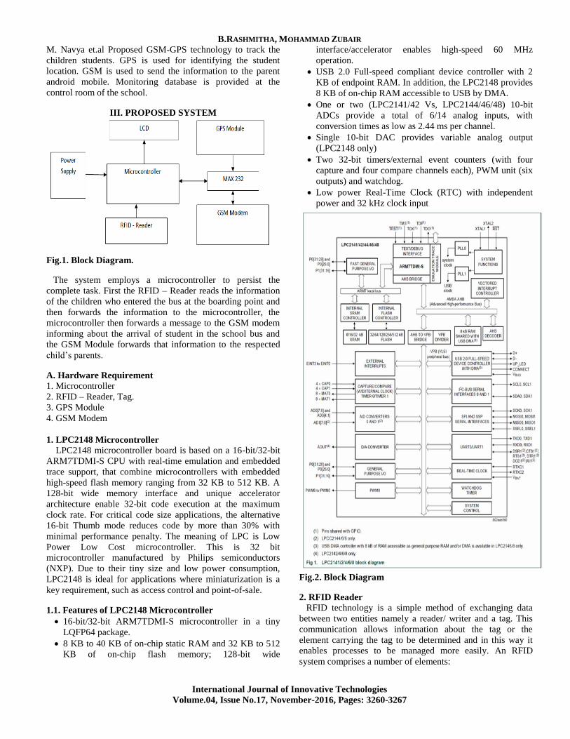
Fig.3. RFID Tag.
3. GSM Modem
GSM, which stands for Global System for Mobile
communications, reigns (important) as the world’s most
widely used cell phone technology. Cell phones use a cell
phone service carrier’s GSM network by searching for cell
phone towers in the nearby area. Global system for mobile
communication (GSM) is a globally accepted standard for
digital cellular communication. GSM is the name of a
standardization group established in 1982 to create a common
European mobile telephone standard that would formulate
specifications for a pan-European mobile cellular radio
system operating at 900 MHz it is estimated that many
countries outside of Europe will join the GSM partnership.
Fig.4. GSM Module.
GSM provides the following features.
Dual Band 900 / 1800MHz
GSM and GPRS Multi slot class -12/10/8
Dual band GSM/GPRS module with size of
29mm*29mm*3.6 mm
Voice / SMS and Data
Accepts Standard SIM Card
Can Be Used On Standard GSM Network Serial Interface
Operating temperature -40 °C to +80 °C
Coding scheme –CS 1,2,3,4
External SIM -3V/1.8V
One user programmable input/output Port
GSM 07.05 and 07.07 other enhanced AT Commands
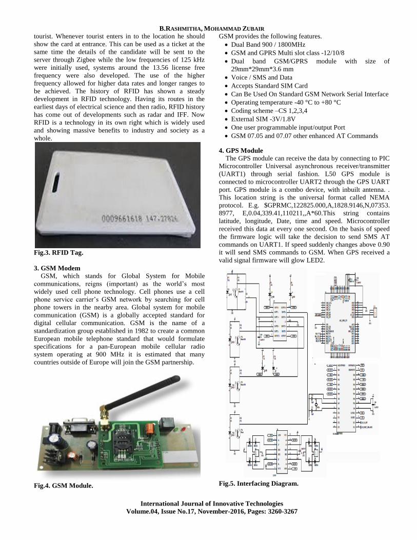
4. GPS Module
The GPS module can receive the data by connecting to PIC
Microcontroller Universal asynchronous receiver/transmitter
(UART1) through serial fashion. L50 GPS module is
connected to microcontroller UART2 through the GPS UART
port. GPS module is a combo device, with inbuilt antenna. .
This location string is the universal format called NEMA
protocol. E.g. $GPRMC,122825.000,A,1828.9146,N,07353.
8977, E,0.04,339.41,110211,,A*60.This string contains
latitude, longitude, Date, time and speed. Microcontroller
received this data at every one second. On the basis of speed
the firmware logic will take the decision to send SMS AT
commands on UART1. If speed suddenly changes above 0.90
it will send SMS commands to GSM. When GPS received a
valid signal firmware will glow LED2.
Fig.5. Interfacing Diagram.

Transportation Safety Enhancement using RFID Technology
International Journal of Innovative Technologies
Volume.04, Issue No.17, November-2016, Pages: 3260-3267
Quectel L50 Read only memory (ROM) based GPS used in
this system. L50 has fast tracked & acquisition features. The
output of GPS L50 has Recommended Minimum
Specification, Global positioning system, Global Navigation
Satellite System, Dilution of Precision (GNSS DOP) and
Active satellite & GNSS Satellite in view Messages body
format. In addition the GPS Module is designed with typical
1.8v power supply, power consumption in Acquisition,
Tracking, Hibernate modes are 45Ma@-130dbm, 35Ma@-
130dbm and 20μA respectively. Receiver type L1, 1575.42
MHz C/A Code.
IV. IMPLEMENTATION AND TESTING A prototype of the system is implemented and tested.
Testing is very crucial part to validate the functionality of the
proposed system. It should be designed to increase the
likelihood of finding an error and checking the functionality
of the proposed system. The units were implemented
individually at first and they were tested to check if they were
working properly. Then, they were integrated and configured
as required for the system. The unit test was held for all the
units in our system: RFID reader and tags, GSM modems and
school server.
A. Bus Unit The bus unit consists of an RFID reader, a GSM modem
and a control unit as shown in Fig.6. The RFID reader detects
the children when they board/leave the bus. It is located inside
the bus. The GSM modem is used to send this data to the
school unit. A microcontroller is used to interface the RFID
reader with the GSM modem.
Fig.6. Bus Unit
1. The RFID Reader The Reader was connected to a PC using RS232 cable. A
terminal program was used to check if the reader can read the
tags by setting the reader parameters appropriately (baud rate,
start bit, data bits, stop bit, parity check bit). This was used to
test the reader support for multi-tag reading and verify the
structure of the tags’ numbers. Fig.7 shows the form of the tag
number as the reader reads them where each tag number
consists of 8 bytes in hexadecimal format.
Fig.7. Testing the RFID Reader and Tags.
2. Microcontroller (At mega 32) ATmega32 microcontroller is used to interface the reader
and the GSM modem in the bus unit for data exchanging as
shown in Fig.8. The reader communicates with
microcontroller using serial communication interface RS232.
However, due to the difference in voltage levels, a max232
chip is used to convert signals from RS232 serial port to
signals suitable for use in TTL compatible digital logic
circuits (power range: 0 V to + 5 V). A C-program was
written to exchange the data between the RFID reader and the
GSM modem through a microcontroller to verify that they
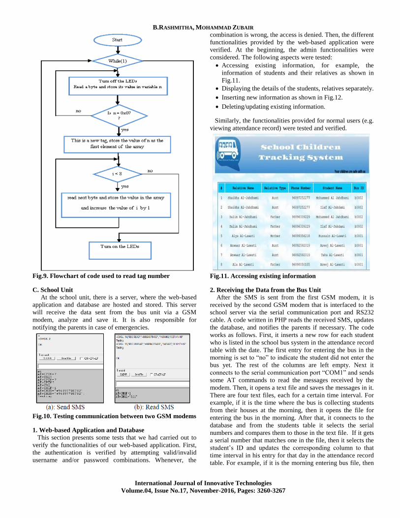
interfaced properly. The flow chart is shown in Fig.9. If the
microcontroller reads the data from the RFID reader, the LED
will be turned on to indicate the successful read of the tag
number.
Fig.8. Reader-microcontroller interface circuit
3. GSM Modem At first, GSM modems connectivity was tested using TMAS
GSM-GPRS modem test program with the AT commands that
are responsible for sending and receiving SMS and calling.
B. Communication between Two Modems Two TMAS GSM/GPRS modems were used to send data
from the bus unit to the school unit. One of modems is located
in the bus unit to send SMS which contains the tag serial
numbers to another GSM modem in the school unit. First,
the communication between these GSM modems were tested
using Terminal program by sending SMS from the first GSM
modem as shown in Fig.10(a) using AT commands. The
second GSM modem received the SMS that the first GSM
modem sent as shown in Fig.10 (b). As obvious from the
Fig.10, the word “Testing” was sent successfully from the
first GSM modem and the second GSM. Then, one GSM
modem was interfaced with the AVR microcontroller
(AtMega8) using RS232. The microcontroller contained the
AT commands, written in C, for sending SMS. The code was
verified using a terminal program to ensure that
microcontroller sent the correct AT commands to GSM
modem.
B.RASHMITHA, MOHAMMAD ZUBAIR
International Journal of Innovative Technologies
Volume.04, Issue No.17, November-2016, Pages: 3260-3267
Fig.9. Flowchart of code used to read tag number
C. School Unit At the school unit, there is a server, where the web-based
application and database are hosted and stored. This server
will receive the data sent from the bus unit via a GSM
modem, analyze and save it. It is also responsible for
notifying the parents in case of emergencies.
Fig.10. Testing communication between two GSM modems
1. Web-based Application and Database This section presents some tests that we had carried out to
verify the functionalities of our web-based application. First,
the authentication is verified by attempting valid/invalid
username and/or password combinations. Whenever, the
combination is wrong, the access is denied. Then, the different
functionalities provided by the web-based application were
verified. At the beginning, the admin functionalities were
considered. The following aspects were tested:
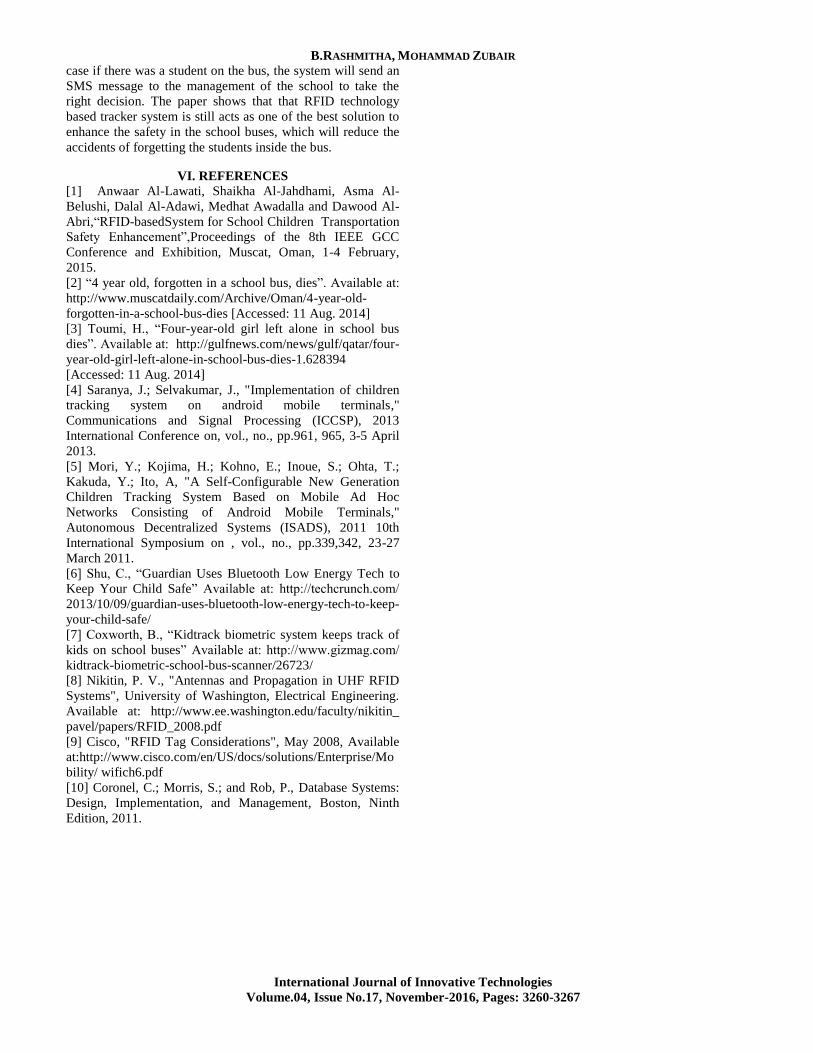
Accessing existing information, for example, the
information of students and their relatives as shown in
Fig.11.
Displaying the details of the students, relatives separately.
Inserting new information as shown in Fig.12.
Deleting/updating existing information.
Similarly, the functionalities provided for normal users (e.g.
viewing attendance record) were tested and verified.
Fig.11. Accessing existing information
2. Receiving the Data from the Bus Unit
After the SMS is sent from the first GSM modem, it is
received by the second GSM modem that is interfaced to the
school server via the serial communication port and RS232
cable. A code written in PHP reads the received SMS, updates
the database, and notifies the parents if necessary. The code
works as follows. First, it inserts a new row for each student
who is listed in the school bus system in the attendance record
table with the date. The first entry for entering the bus in the
morning is set to “no” to indicate the student did not enter the
bus yet. The rest of the columns are left empty. Next it
connects to the serial communication port “COM1” and sends
some AT commands to read the messages received by the
modem. Then, it opens a text file and saves the messages in it.
There are four text files, each for a certain time interval. For
example, if it is the time where the bus is collecting students
from their houses at the morning, then it opens the file for
entering the bus in the morning. After that, it connects to the
database and from the students table it selects the serial
numbers and compares them to those in the text file. If it gets
a serial number that matches one in the file, then it selects the
student’s ID and updates the corresponding column to that
time interval in his entry for that day in the attendance record
table. For example, if it is the morning entering bus file, then

Transportation Safety Enhancement using RFID Technology
International Journal of Innovative Technologies
Volume.04, Issue No.17, November-2016, Pages: 3260-3267
it updates ATTEND_MOR_ENTR column which corresponds
to this time.
Fig.12. Add new information.
Fig.13. The parent notification message
Fig.14. SMS gateway test.
After the entries for all students that appeared in the text
file are updated, the system checks the students that did not
enter/leave the bus. If there is a child who did not enter/leave
the bus, the system gets his relative’s information from the
database and sends a notification in the chosen language. The
sent message contains the student name (useful for parents
with multiple children) and bus driver’s phone number as
shown in Fig.13.
3. SMS Notifications The PHP code written for the SMS gateway was tested. To
use the SMS gateway, the following parameters are set: user
ID, password, language, recipients, and the messages. The
user ID and password are given by the gateway provider. The
language has to be set before writing the text so that it can be
sent properly. There are many integer values for different
languages. For English, the value is 0 and for Arabic the value
is 64. The text can be set to whatever the user wants to send.
The result of testing the code is shown in Fig.14.
4. The system Integration Test
The integrated system shown in Fig.15 was tested and the
results are shown in table 1.
Fig.15. The full integrated system
Table 1. Integration test for the whole system
V. CONCLUSION
The integration of RFID and GSM technologies for safety
and security purpose is very important nowadays due to
increase in accidents of children gets missed out at the bus
which may lead to death due to suffocation. In this project,
bus safety system for school children has been developed.
Using this system, concerned authorities, bus driver can be
alerted as it’s visible from the RFID card. At the same time, in
B.RASHMITHA, MOHAMMAD ZUBAIR
International Journal of Innovative Technologies
Volume.04, Issue No.17, November-2016, Pages: 3260-3267
case if there was a student on the bus, the system will send an
SMS message to the management of the school to take the
right decision. The paper shows that that RFID technology
based tracker system is still acts as one of the best solution to
enhance the safety in the school buses, which will reduce the
accidents of forgetting the students inside the bus.
VI. REFERENCES
[1] Anwaar Al-Lawati, Shaikha Al-Jahdhami, Asma Al-
Belushi, Dalal Al-Adawi, Medhat Awadalla and Dawood Al-
Abri,“RFID-basedSystem for School Children Transportation
Safety Enhancement”,Proceedings of the 8th IEEE GCC
Conference and Exhibition, Muscat, Oman, 1-4 February,
2015.
[2] “4 year old, forgotten in a school bus, dies”. Available at:
http://www.muscatdaily.com/Archive/Oman/4-year-old-
forgotten-in-a-school-bus-dies [Accessed: 11 Aug. 2014]
[3] Toumi, H., “Four-year-old girl left alone in school bus
dies”. Available at: http://gulfnews.com/news/gulf/qatar/four-
year-old-girl-left-alone-in-school-bus-dies-1.628394
[Accessed: 11 Aug. 2014]
[4] Saranya, J.; Selvakumar, J., "Implementation of children
tracking system on android mobile terminals,"
Communications and Signal Processing (ICCSP), 2013
International Conference on, vol., no., pp.961, 965, 3-5 April
2013.
[5] Mori, Y.; Kojima, H.; Kohno, E.; Inoue, S.; Ohta, T.;
Kakuda, Y.; Ito, A, "A Self-Configurable New Generation
Children Tracking System Based on Mobile Ad Hoc
Networks Consisting of Android Mobile Terminals,"
Autonomous Decentralized Systems (ISADS), 2011 10th
International Symposium on , vol., no., pp.339,342, 23-27
March 2011.
[6] Shu, C., “Guardian Uses Bluetooth Low Energy Tech to
Keep Your Child Safe” Available at: http://techcrunch.com/
2013/10/09/guardian-uses-bluetooth-low-energy-tech-to-keep-
your-child-safe/
[7] Coxworth, B., “Kidtrack biometric system keeps track of
kids on school buses” Available at: http://www.gizmag.com/
kidtrack-biometric-school-bus-scanner/26723/
[8] Nikitin, P. V., "Antennas and Propagation in UHF RFID
Systems", University of Washington, Electrical Engineering.
Available at: http://www.ee.washington.edu/faculty/nikitin_
pavel/papers/RFID_2008.pdf
[9] Cisco, "RFID Tag Considerations", May 2008, Available
at:http://www.cisco.com/en/US/docs/solutions/Enterprise/Mo
bility/ wifich6.pdf
[10] Coronel, C.; Morris, S.; and Rob, P., Database Systems:
Design, Implementation, and Management, Boston, Ninth
Edition, 2011.