Embed Size (px)
Citation preview
OPTICAL PUMPINGTrapping Electrons With Light
Elijah K. Dunn
PHSX 516, Dec. 6, 2011
Motivation
Demonstrate Zeeman Splitting Determine the g-factor of Rb85 and Rb87
Optical pumping lab rarely gets completed by students
“It is only a small exaggeration to claim these [optical pumping] experiments constitute an atomic physics course.”
-TeachSpin Manual
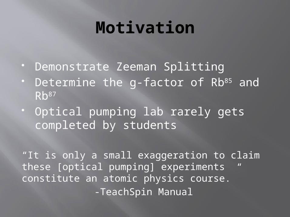
Zeeman Splitting
• Fine and Hyperfine states from electron spin dipoles and orbit fields
• In the presence of a magnetic field Hyperfine energy states () are split
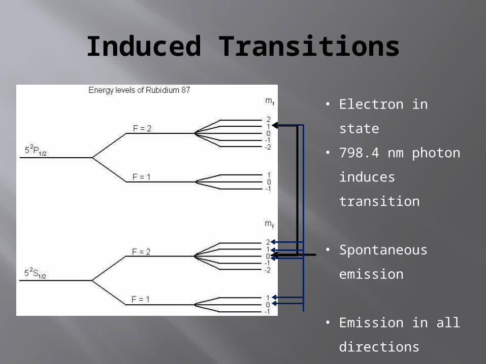
Induced Transitions
• Electron in state
• 798.4 nm photon
induces transition
• Spontaneous
emission
• Emission in all
directions
• Start again!
Pumping
Electrons emit a photon and loose energy Electrons can deexcite to any Zeeman
state with equal probability Highest Zeeman state of the non-excited
energy level can not gain a unit of angular momentum
Electrons cannot transition and will accumulate in that level
They have been “pumped” with optical waves!
Zero Field Transition
Electrons are in the pumped state Maximum transmission of light Magnetic field diminishes to zero Zeeman states collapse Light transmission decreases as
absorption increases
EM Transition
Electrons are in the pumped state Maximum transmission of light Input EM wave matches the energy
difference between Zeeman states Transitions occur that drop the electrons
out of the pumped state Light transmission decreases as
absorption increases

Apparatus
1. RF discharge lamp2. Optics3. Pumping Cell4. Optics5. Detector6. Magnetic Coils

Optics
RF discharge lamp provides light Composed of Rb85, Rb87 and Xenon gas (buffer)
Plano-convex lens to collimate Interference filter to transmit 798.4 nm
light Linear polarizer ¼ wave plate to circularly polarize light
Ensures direction independent absorption Plano-convex lens for focusing Photodiode detector
Magnetic Coils
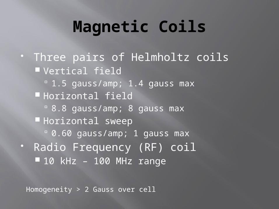
Three pairs of Helmholtz coils Vertical field
1.5 gauss/amp; 1.4 gauss max Horizontal field
8.8 gauss/amp; 8 gauss max Horizontal sweep
0.60 gauss/amp; 1 gauss max Radio Frequency (RF) coil
10 kHz – 100 MHz range
Homogeneity > 2 Gauss over cell
Detection
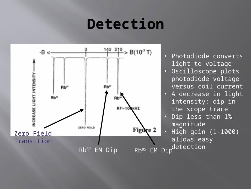
• Photodiode converts light to voltage
• Oscilloscope plots photodiode voltage versus coil current
• A decrease in light intensity: dip in the scope trace
• Dip less than 1% magnitude
• High gain (1-1000) allows easy detection
Zero Field Transition
Rb87 EM Dip Rb85 EM Dip
Methodology
Temperature stabilization Alignment Gain settings Sweep the horizontal field Locate Zero Field Transition Minimize width with vertical field coil Input EM wave Search for EM dip Change frequency

Error and Uncertainty
Coil Current Current conversion less than 1% offset Voltmeter uncertainty (0.15%±2)
Inhomogeneity of Helmholtz coil fields Alignment parallel to geomagnetic field Area magnetic fields
Moving elevator Metallic structure

Results
mG
Conclusions
Expected is low Demonstrated optical pumping for two
isotopes Magnetically isolate apparatus and
measure R in the future
Acknowledgements
My partner: S. Halder Physics Dept. for providing the $14,000
Optical Pumping Apparatus Prof. Han for suggestions and help