Embed Size (px)
Citation preview

TraversingTraversing
Chapter 9 Chapter 9

Closed Traverse Showing Interior AnglesClosed Traverse Showing Interior Angles

Open Traverse Showing Deflection AnglesOpen Traverse Showing Deflection Angles
Computation of Interior and Exterior Angle at Computation of Interior and Exterior Angle at STA 1 + 43.26STA 1 + 43.26

Computation of AzimuthsComputation of Azimuths

Computation of BearingsComputation of Bearings

Traverse ComputationsTraverse Computations
Chapter 10Chapter 10

Step 1: Check Allowable Angle MisclosureStep 1: Check Allowable Angle Misclosure
where:
c is the allowable misclosure in seconds
K is a constant that depends on the level of accuracy specified for the survey
n is the number of angles
Federal Geodetic Control Subcommittee (FGCS) recommends:
First order 1.7”
Second-order class I 3”
Second-order class II 4.5”
Third-order class I 10”
Third-order class II 20”
c K n
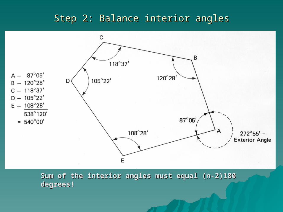
Step 2: Balance interior anglesStep 2: Balance interior angles
Sum of the interior angles must equal (n-2)180 Sum of the interior angles must equal (n-2)180 degrees!degrees!

Procedures for Balancing AnglesProcedures for Balancing Angles
Method 1: Multiple Measurements: Use weighted average based on standard errors of angular measurements.
Method 2: Single Measurements: Apply an average correction to each angle where observing conditions were approximately the same at all stations. The correction is computed for each angle by dividing the total angular misclosure by the number of angles.
Method 3: Single Measurements: Make larger corrections to angles where poor observing conditions were present. This method is seldom used.

Step 3:Step 3: Computation of Preliminary Azimuths or BearingsComputation of Preliminary Azimuths or Bearings

Step 3:Step 3: Computation of Preliminary Azimuths or Bearings Computation of Preliminary Azimuths or Bearings (continued)(continued)
Beginning at the reference meridian compute the azimuth or bearing for each leg of the traverse.
Always check the last leg of the traverse to make sure that you compute the same azimuth or bearing as the reference meridian.

Step 4:Step 4: Compute Departures and LatitudesCompute Departures and Latitudes

Step 4:Step 4: Compute Departures and Latitudes (continued)Compute Departures and Latitudes (continued)
departure = L sin (bearing)
latitude = L cos (bearing)

Step 5:Step 5: Compute Linear MisclosureCompute Linear Misclosure
Because of errors in the measured angles and distances Because of errors in the measured angles and distances there will be a linear misclosure of the traverse. Another there will be a linear misclosure of the traverse. Another way of illustrating this is that once you go around the way of illustrating this is that once you go around the traverse from point A back to point A’ you will notice that traverse from point A back to point A’ you will notice that the summation of the departures and latitudes do not the summation of the departures and latitudes do not equal to zero. Hence a linear misclosure is introduced.equal to zero. Hence a linear misclosure is introduced.

Step 5:Step 5: Compute Linear Misclosure (continued)Compute Linear Misclosure (continued)
Linear misclosure = [(departure misclosure)Linear misclosure = [(departure misclosure)22 + (latitude misclosure) + (latitude misclosure)2]1/22]1/2
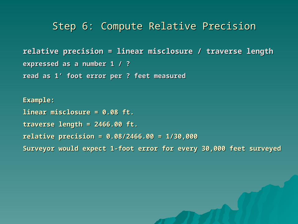
Step 6:Step 6: Compute Relative PrecisionCompute Relative Precision
relative precision = linear misclosure / traverse lengthrelative precision = linear misclosure / traverse length
expressed as a number 1 / ?expressed as a number 1 / ?
read as 1’ foot error per ? feet measuredread as 1’ foot error per ? feet measured
Example:Example:
linear misclosure = 0.08 ft.linear misclosure = 0.08 ft.
traverse length = 2466.00 ft.traverse length = 2466.00 ft.
relative precision = 0.08/2466.00 = 1/30,000relative precision = 0.08/2466.00 = 1/30,000
Surveyor would expect 1-foot error for every 30,000 feet surveyedSurveyor would expect 1-foot error for every 30,000 feet surveyed

1984 FGCS Horizontal Control Survey Accuracy Standards1984 FGCS Horizontal Control Survey Accuracy Standards
Order and ClassOrder and Class Relative Accuracy RequiredRelative Accuracy Required
First OrderFirst Order 1 part in 100,0001 part in 100,000
Second OrderSecond Order
Class IClass I 1 part in 50,0001 part in 50,000
Class IIClass II 1 part in 20,0001 part in 20,000
Third OrderThird Order
Class IClass I 1 part in 10,0001 part in 10,000
Class IIClass II 1 part in 5,0001 part in 5,000
From Table 19-3, page 557 in your textbookFrom Table 19-3, page 557 in your textbook

Step 7:Step 7: Adjust Departures and LatitudesAdjust Departures and Latitudes
Methods:Methods:
Compass (Bowditch) Rule:Compass (Bowditch) Rule:
correction in departure for AB = - [(total departure misclosure)/(traverse perimeter)](length of AB)correction in departure for AB = - [(total departure misclosure)/(traverse perimeter)](length of AB)
correction in latitude for AB = - [(total latitude misclosure)/(traverse perimeter)](length of AB)correction in latitude for AB = - [(total latitude misclosure)/(traverse perimeter)](length of AB)
Adjusts the departures and latitudes of the sides of the traverse in proportion to their lengths.Adjusts the departures and latitudes of the sides of the traverse in proportion to their lengths.
Least Squares Adjustment:Least Squares Adjustment:
Rigorous but best method based on probabilistic approach which models the occurrence of random Rigorous but best method based on probabilistic approach which models the occurrence of random errors. Angle and distance measurements are adjusted simultaneously. Most computer programs errors. Angle and distance measurements are adjusted simultaneously. Most computer programs employ a least square adjustment methodology.employ a least square adjustment methodology.
For more information on Least Squares Method see Chapter 15 in your textbook.For more information on Least Squares Method see Chapter 15 in your textbook.

Step 8: Compute Rectangular CoordinatesStep 8: Compute Rectangular Coordinates
XXBB = X = XAA + departure AB + departure AB
YYBB = Y = YAA + latitude AB + latitude AB

Step 8: Compute Rectangular Coordinates (continued)Step 8: Compute Rectangular Coordinates (continued)
Compute the coordinates of all points on the traverse taking into Compute the coordinates of all points on the traverse taking into account the signs of the latitudes and departures for each side of the account the signs of the latitudes and departures for each side of the traverse. Be sure to compute the coordinates of the beginning point traverse. Be sure to compute the coordinates of the beginning point (in this case A) so you can check to see if you have made any errors in (in this case A) so you can check to see if you have made any errors in your computations.your computations.

Signs of Departures and LatitudesSigns of Departures and Latitudes
NorthNorth
EastEastWestWest
SouthSouth
Departure (+)Departure (+)
Latitude (+)Latitude (+)
Departure (-)Departure (-)
Latitude (+)Latitude (+)
Departure (+)Departure (+)
Latitude (-)Latitude (-)
Departure (-)Departure (-)
Latitude (-)Latitude (-)

Step 9: Compute Final Adjusted Traverse Lengths and BearingsStep 9: Compute Final Adjusted Traverse Lengths and Bearings
To compute adjusted bearing AB:To compute adjusted bearing AB:
tan (bearing) AB = (corrected departure AB)/(corrected latitude AB)tan (bearing) AB = (corrected departure AB)/(corrected latitude AB)
To compute adjusted length AB:To compute adjusted length AB:
length AB = [(corrected departure AB)length AB = [(corrected departure AB)22 + (corrected latitude AB) + (corrected latitude AB)22]]1/21/2

Coordinate Geometry (COGO)Coordinate Geometry (COGO)
Formulas:Formulas:
tan azimuth (or bearing) AB = departure AB/latitude ABtan azimuth (or bearing) AB = departure AB/latitude AB
length AB = departure AB/(sin azimuth (or bearing) AB)length AB = departure AB/(sin azimuth (or bearing) AB)
length AB = latitude AB/(cos azimuth (or bearing) AB)length AB = latitude AB/(cos azimuth (or bearing) AB)
length AB = length AB = [(departure AB)length AB = length AB = [(departure AB)22 + (latitude AB) + (latitude AB)22]]1/21/2
departure AB = Xdeparture AB = XBB – X – XAA = delta X = delta X
latitude AB = Ylatitude AB = YBB – Y – YAA = delta Y = delta Y
delta Y (latitude)delta Y (latitude)
delta X (departure)delta X (departure)
Bearing angleBearing angle
BB
AA

Coordinate Geometry (COGO) (continued)Coordinate Geometry (COGO) (continued)
More formulas:More formulas:
tan azimuth (or bearing) AB = (Xtan azimuth (or bearing) AB = (XBB – X – XAA)/(Y)/(YBB – Y – YAA) = (delta x)/(delta y)) = (delta x)/(delta y)
length AB = (Xlength AB = (XBB – X – XAA)/(sin azimuth (or bearing) AB))/(sin azimuth (or bearing) AB)
length AB = (Ylength AB = (YBB – Y – YAA)/(cos azimuth (or bearing) AB))/(cos azimuth (or bearing) AB)
length AB = [(Xlength AB = [(XBB – X – XAA ) )22 + (Y + (YBB – Y – YAA ) )22]]1/21/2
Length AB = [(delta X)Length AB = [(delta X)22 + (delta Y) + (delta Y)22]]1/21/2
These types of calculations are referred to as “inversing” between two These types of calculations are referred to as “inversing” between two points. i.e. if you know the coordinates of two points you can easily points. i.e. if you know the coordinates of two points you can easily find the bearing between the two points and the distance between the find the bearing between the two points and the distance between the two points by using the above formulas.two points by using the above formulas.
Area ComputationsArea Computations
Chapter 12Chapter 12

Step 10: Compute Area using Coordinate MethodStep 10: Compute Area using Coordinate Method
)(2
DEDE
YYXX
areaE’EDD’E’ = )(2
DEDE
YYXX
YE = E’ – C’
YD = D’ – C’
Each of the areas of Each of the areas of trapezoids and triangles trapezoids and triangles can be expressed by can be expressed by multiplying coordinates multiplying coordinates in a similar manner.in a similar manner.

Step 10: Compute Area using Coordinate Method (continued)Step 10: Compute Area using Coordinate Method (continued)
Double area = +XDouble area = +XAAYYBB+X+XBBYYcc+X+XccYYDD+X+XDDYYEE+X+XEEYYAA
-X-XBBYYA A –X–XccYYB B –X–XDDYYC C –X–XEEYYD D -X-XAAYYEE
An easy way to remember how to compute An easy way to remember how to compute the area using the coordinate method:the area using the coordinate method:
Be sure to begin and end at the same Be sure to begin and end at the same coordinate. The products are computed coordinate. The products are computed along the diagonals with dashed arrows along the diagonals with dashed arrows considered plus and solid ones minus. This considered plus and solid ones minus. This method computes the DOUBLE AREA so method computes the DOUBLE AREA so you need to divide the result by 2 to get you need to divide the result by 2 to get the area.the area.