Embed Size (px)
Citation preview

TREATMENT PLANNING: Corrections and Beam Shaping
Dr. Kazi S. Manir
Where we are
• Standard Clinical scenario
P
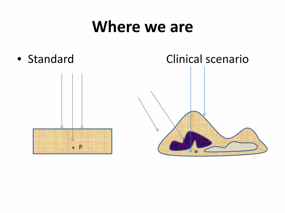
correction
Standard condition
Flat surface
Homogenous unit density phantom Perpendicular beam incidence
Reality
Irregular/curved surface Needs correction /compensation
Tissue in-homogeneity Needs correction
Oblique/tangential Needs correction
Irregular/curved surface contour correction
1. Corrections 2. Tissue compensation (Bolus/Compensator) 3. Wedge compensators 4. Multiple fields
Basic correction principle
Correction method: TPS algorithm Basic principles : 1.Effective SSD method 2.TAR/TMR method 3.Isodose shift method
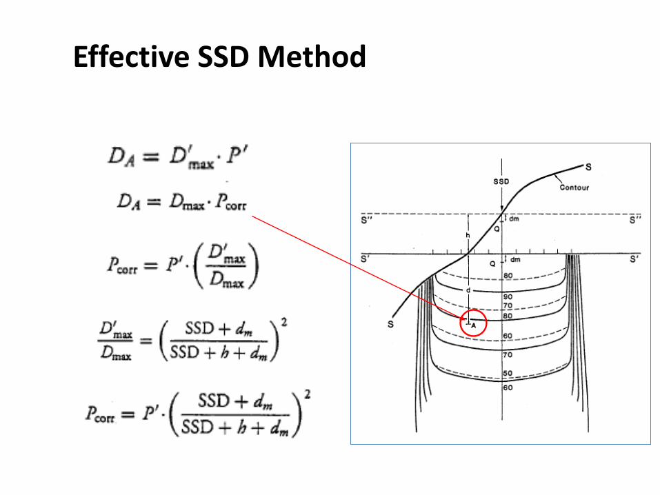
Effective SSD Method
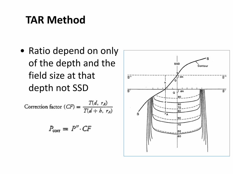
TAR Method
• Ratio depend on only of the depth and the field size at that depth not SSD
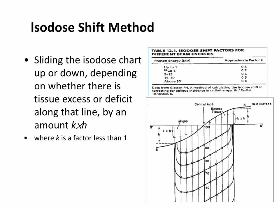
lsodose Shift Method
• Sliding the isodose chart up or down, depending on whether there is tissue excess or deficit along that line, by an amount k×h
• where k is a factor less than 1
Irregular/curved surface contour correction
1. Corrections 2. Tissue compensation (Bolus/Compensator) 3. Wedge compensators 4. Multiple fields
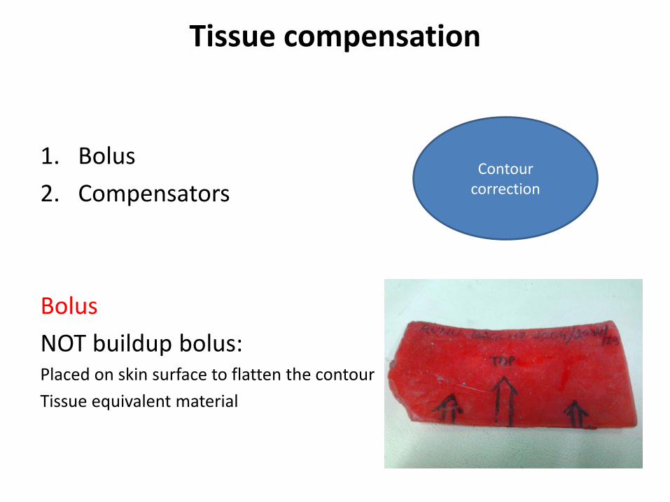
Tissue compensation
1. Bolus 2. Compensators Bolus NOT buildup bolus: Placed on skin surface to flatten the contour Tissue equivalent material
Contour correction
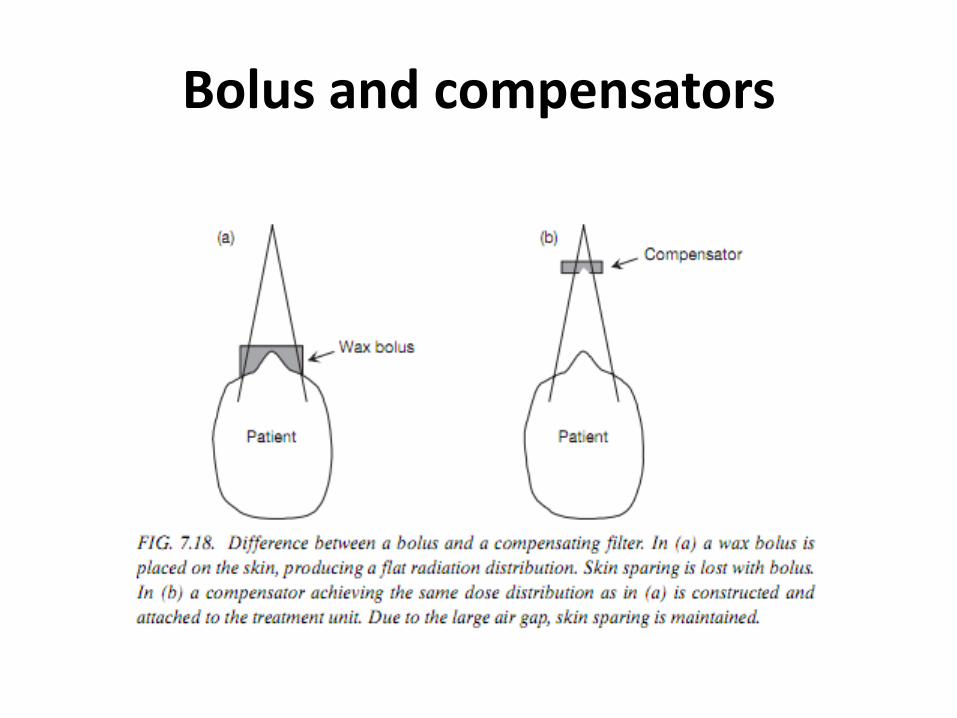
Bolus and compensators
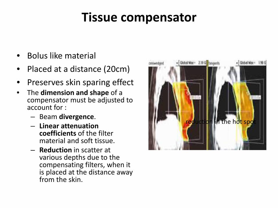
Tissue compensator
• Bolus like material • Placed at a distance (20cm) • Preserves skin sparing effect • The dimension and shape of a
compensator must be adjusted to account for : – Beam divergence. – Linear attenuation
coefficients of the filter material and soft tissue.
– Reduction in scatter at various depths due to the compensating filters, when it is placed at the distance away from the skin.
reduction in the hot spot
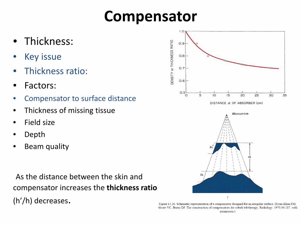
Compensator • Thickness: • Key issue • Thickness ratio: • Factors: • Compensator to surface distance • Thickness of missing tissue • Field size • Depth • Beam quality
As the distance between the skin and compensator increases the thickness ratio (h’/h) decreases.
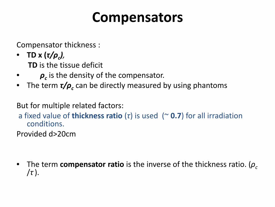
Compensators Compensator thickness : • TD x (τ/ρc), TD is the tissue deficit • ρc is the density of the compensator. • The term τ/ρc can be directly measured by using phantoms But for multiple related factors: a fixed value of thickness ratio (τ) is used (~ 0.7) for all irradiation
conditions. Provided d>20cm
• The term compensator ratio is the inverse of the thickness ratio. (ρc
/τ ).
Compensators
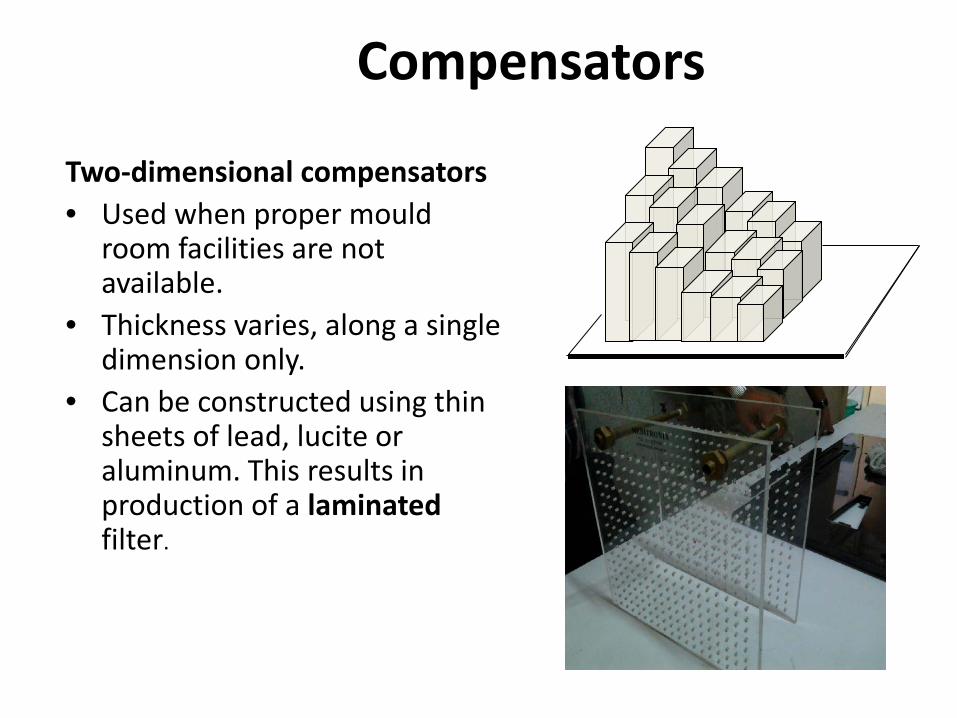
Two-dimensional compensators • Used when proper mould
room facilities are not available.
• Thickness varies, along a single dimension only.
• Can be constructed using thin sheets of lead, lucite or aluminum. This results in production of a laminated filter.
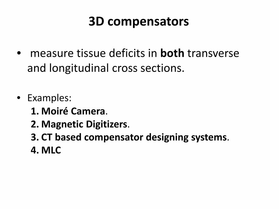
3D compensators
• measure tissue deficits in both transverse and longitudinal cross sections.
• Examples: 1. Moiré Camera. 2. Magnetic Digitizers. 3. CT based compensator designing systems. 4. MLC
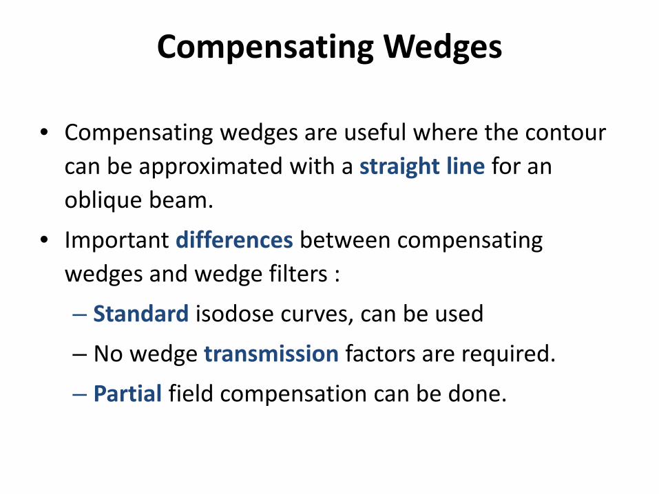
Compensating Wedges
• Compensating wedges are useful where the contour can be approximated with a straight line for an oblique beam.
• Important differences between compensating wedges and wedge filters : – Standard isodose curves, can be used – No wedge transmission factors are required. – Partial field compensation can be done.
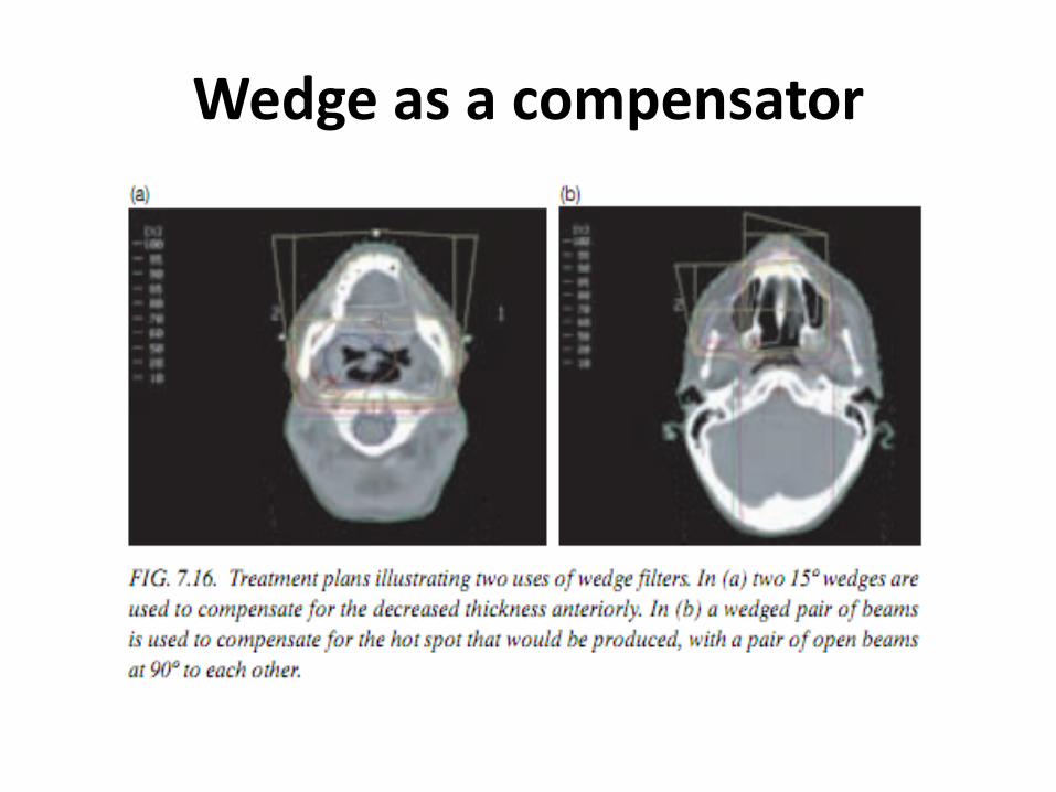
Wedge as a compensator
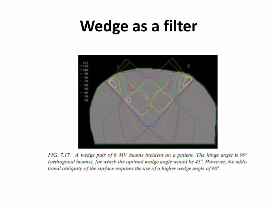
Wedge as a filter
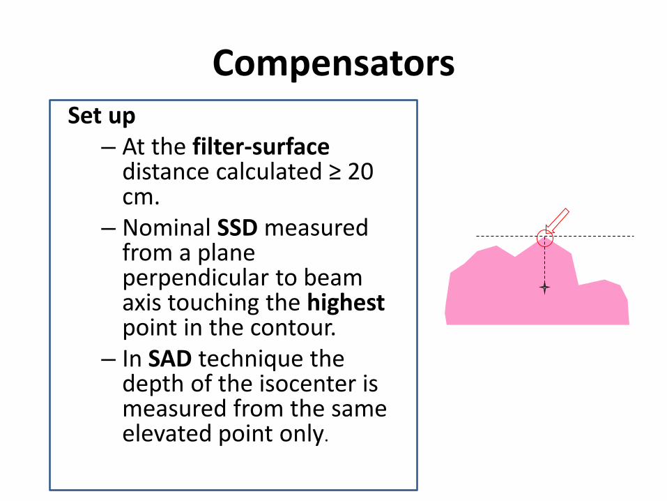
Compensators Set up
– At the filter-surface distance calculated ≥ 20 cm.
– Nominal SSD measured from a plane perpendicular to beam axis touching the highest point in the contour.
– In SAD technique the depth of the isocenter is measured from the same elevated point only.
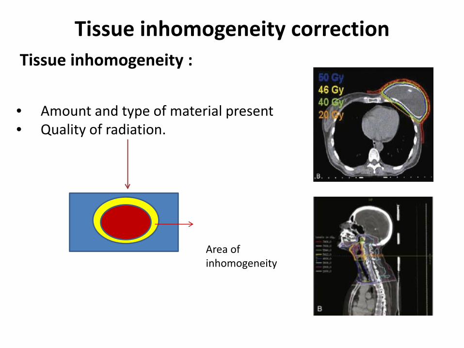
Tissue inhomogeneity correction Tissue inhomogeneity : • Amount and type of material present • Quality of radiation.
Area of inhomogeneity
The effects of tissue inhomogeneities:
• changes in the absorption of the primary beam and scattered photons
• primary beam : points that lie beyond the inhomogeneity,
• Scattered : points near the inhomogeneity
• changes in the secondary electron fluence
• tissues within the inhomogeneity and at the boundaries.
Problems ?
1.Beam attenuation & scattering needs correction 2.Absorbed dose within inhomogeneity needs correction
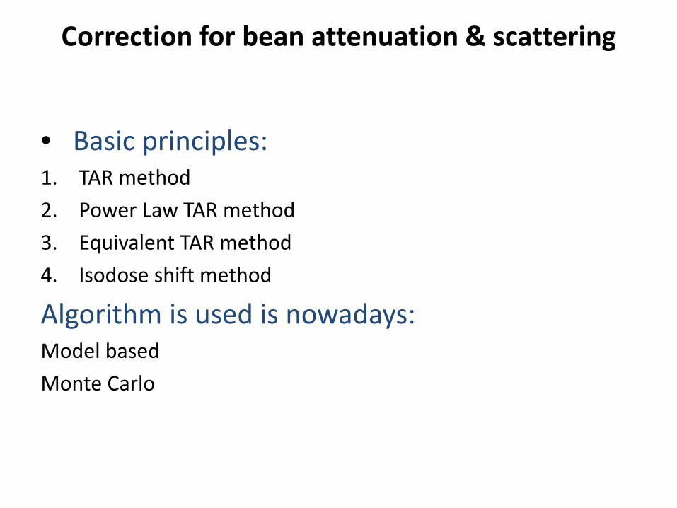
Correction for bean attenuation & scattering
• Basic principles: 1. TAR method 2. Power Law TAR method 3. Equivalent TAR method 4. Isodose shift method
Algorithm is used is nowadays: Model based Monte Carlo
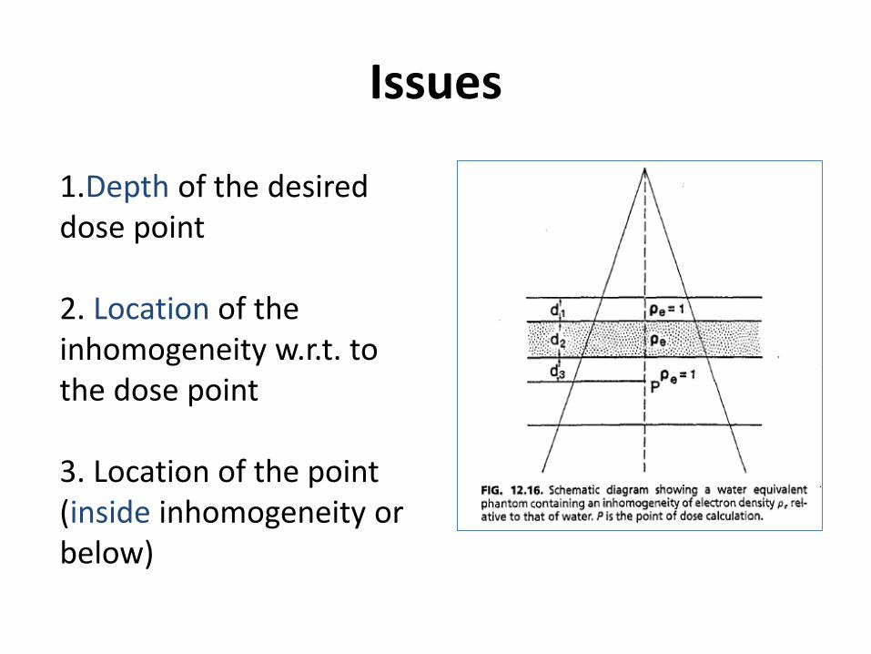
Issues
1.Depth of the desired dose point 2. Location of the inhomogeneity w.r.t. to the dose point 3. Location of the point (inside inhomogeneity or below)
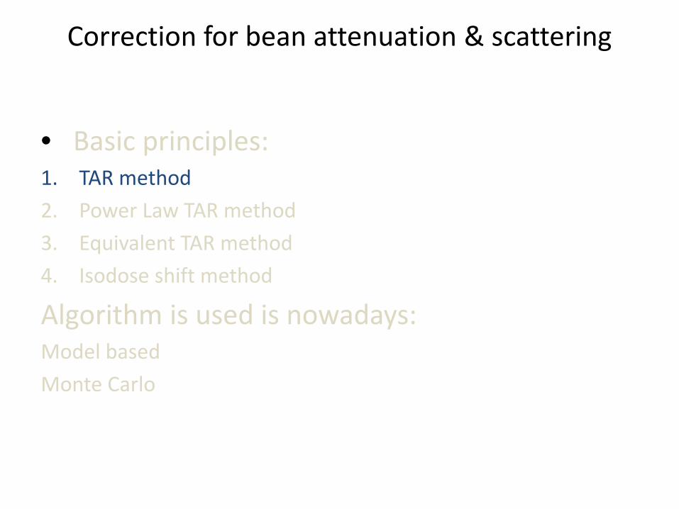
Correction for bean attenuation & scattering
• Basic principles: 1. TAR method 2. Power Law TAR method 3. Equivalent TAR method 4. Isodose shift method
Algorithm is used is nowadays: Model based Monte Carlo
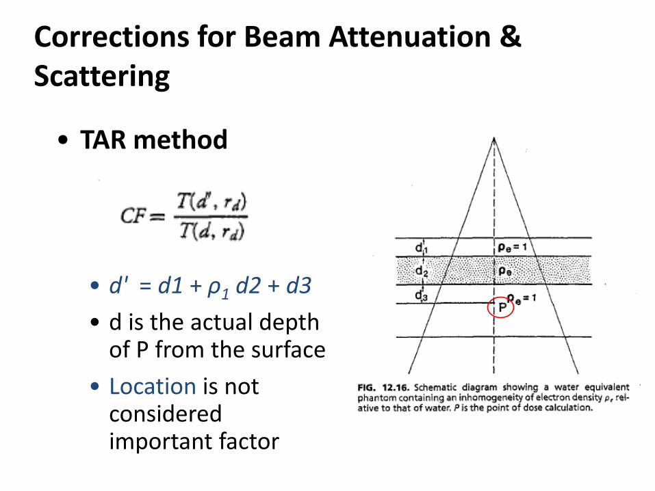
Corrections for Beam Attenuation & Scattering
• TAR method
• d' = d1 + ρ1 d2 + d3 • d is the actual depth
of P from the surface • Location is not
considered important factor
Correction for bean attenuation & scattering
• Basic principles: 1. TAR method 2. Power Law TAR method 3. Equivalent TAR method 4. Isodose shift method
Algorithm is used is nowadays: Model based Monte Carlo
Corrections for Beam Attenuation and Scattering
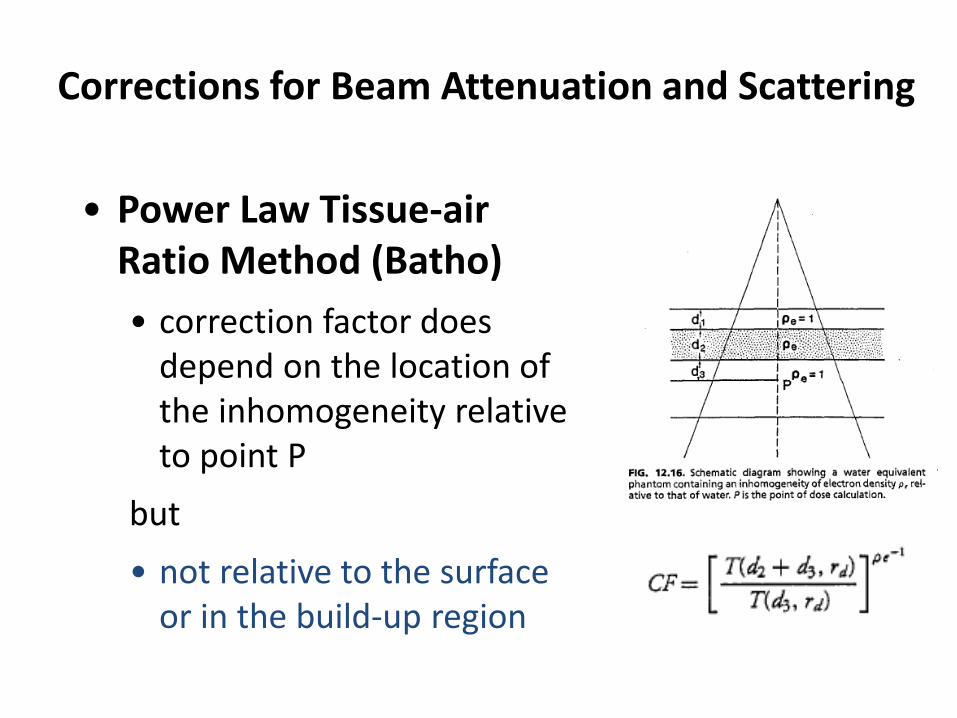
• Power Law Tissue-air Ratio Method (Batho) • correction factor does
depend on the location of the inhomogeneity relative to point P
but • not relative to the surface
or in the build-up region
Corrections for Beam Attenuation & Scattering
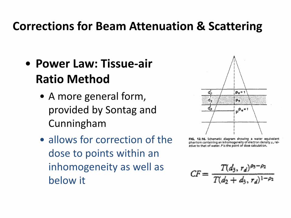
• Power Law: Tissue-air Ratio Method • A more general form,
provided by Sontag and Cunningham
• allows for correction of the dose to points within an inhomogeneity as well as below it
Correction for bean attenuation & scattering
• Basic principles: 1. TAR method 2. Power Law TAR method 3. Equivalent TAR method 4. Isodose shift method
Algorithm is used is nowadays: Model based Monte Carlo
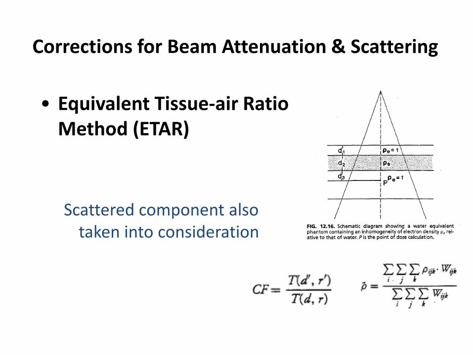
Corrections for Beam Attenuation & Scattering
• Equivalent Tissue-air Ratio Method (ETAR) Scattered component also
taken into consideration
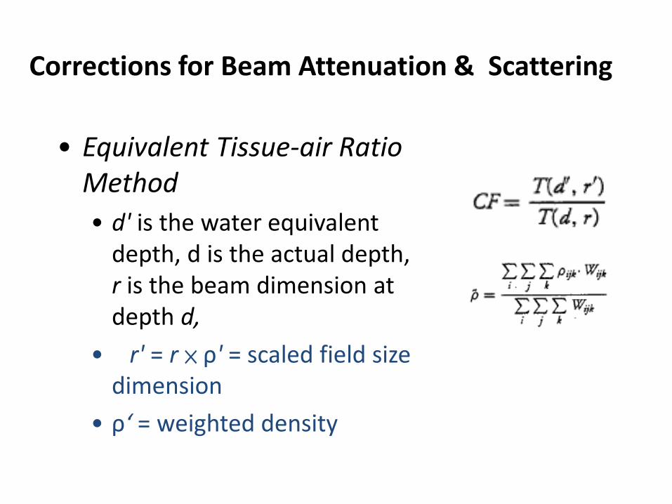
Corrections for Beam Attenuation & Scattering
• Equivalent Tissue-air Ratio Method • d' is the water equivalent
depth, d is the actual depth, r is the beam dimension at depth d,
• r' = r × ρ' = scaled field size dimension
• ρ‘ = weighted density
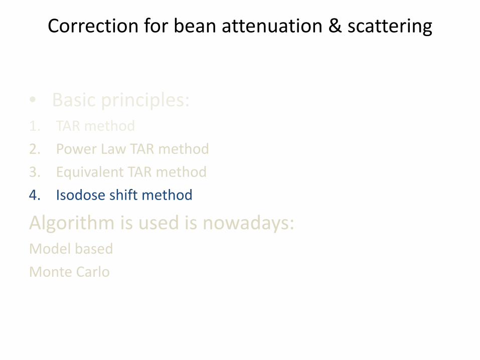
Correction for bean attenuation & scattering
• Basic principles: 1. TAR method 2. Power Law TAR method 3. Equivalent TAR method 4. Isodose shift method
Algorithm is used is nowadays: Model based Monte Carlo
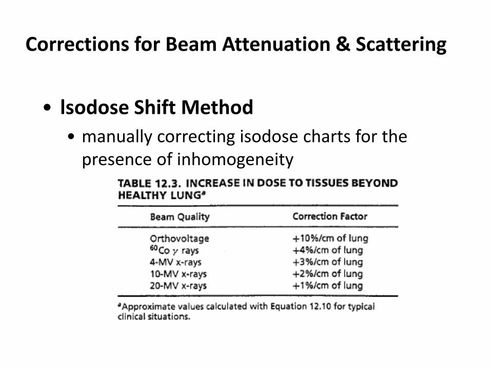
Corrections for Beam Attenuation & Scattering
• lsodose Shift Method • manually correcting isodose charts for the
presence of inhomogeneity
Corrections for Beam Attenuation & Scattering
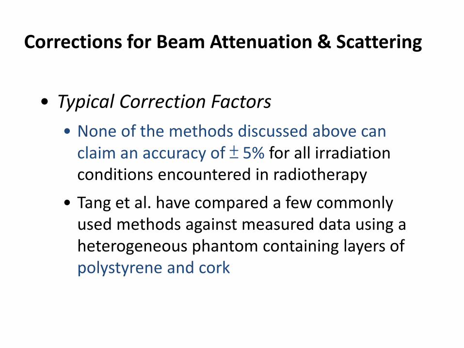
• Typical Correction Factors • None of the methods discussed above can
claim an accuracy of ± 5% for all irradiation conditions encountered in radiotherapy
• Tang et al. have compared a few commonly used methods against measured data using a heterogeneous phantom containing layers of polystyrene and cork
Corrections for Beam Attenuation & Scattering
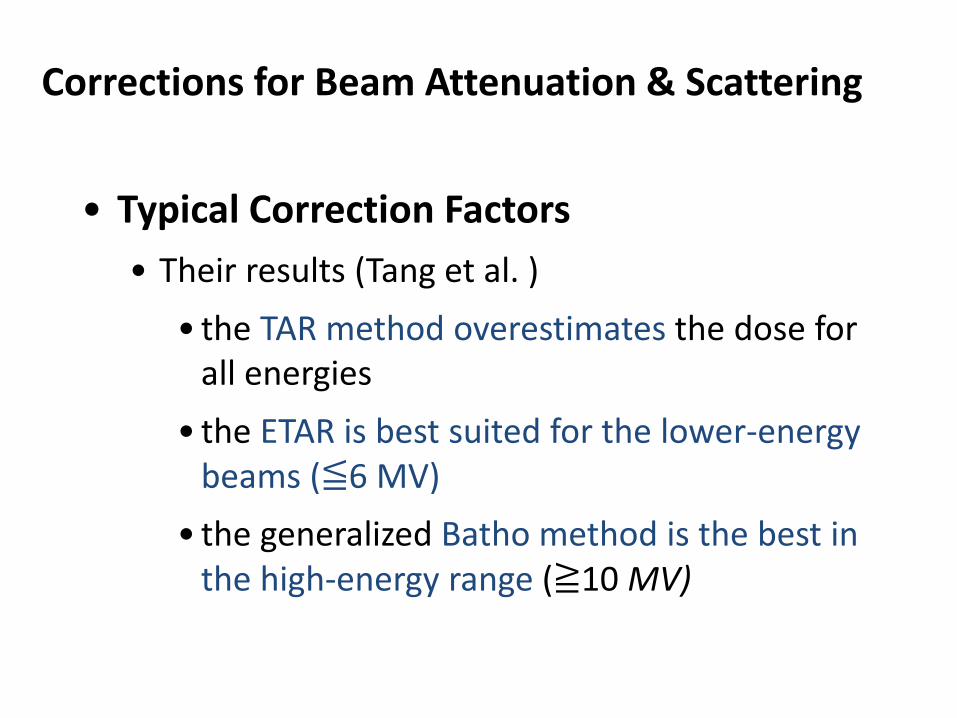
• Typical Correction Factors • Their results (Tang et al. )
• the TAR method overestimates the dose for all energies
• the ETAR is best suited for the lower-energy beams (≦6 MV)
• the generalized Batho method is the best in the high-energy range (≧10 MV)
Problems ?
1.Beam attenuation & scattering needs correction 2.Absorbed dose within inhomogeneity needs correction
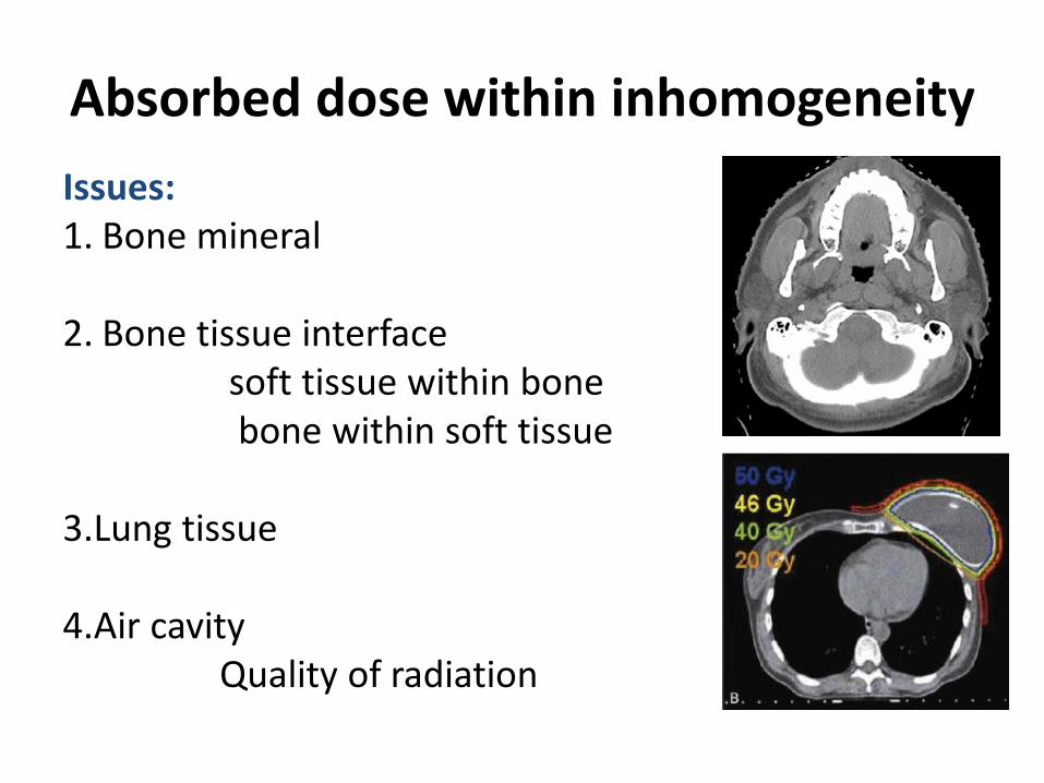
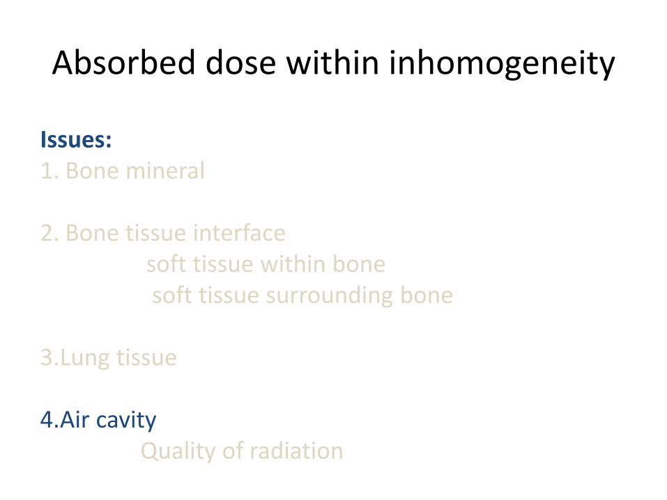
Absorbed dose within inhomogeneity Issues: 1. Bone mineral
2. Bone tissue interface soft tissue within bone bone within soft tissue 3.Lung tissue 4.Air cavity Quality of radiation
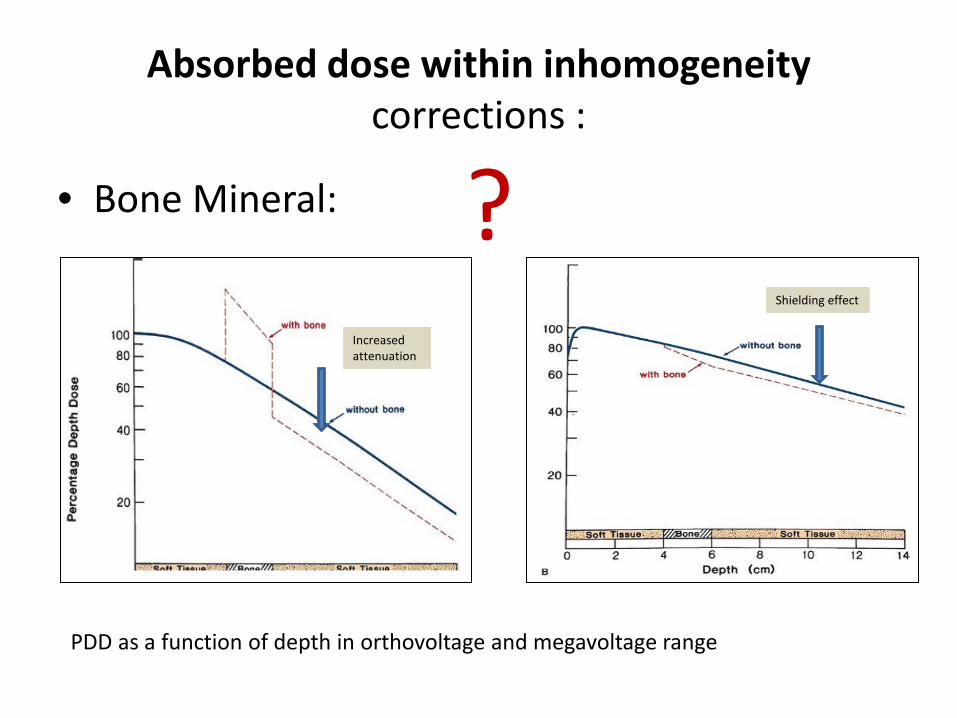
Absorbed dose within inhomogeneity corrections :
• Bone Mineral:
PDD as a function of depth in orthovoltage and megavoltage range
Increased attenuation
Shielding effect
?
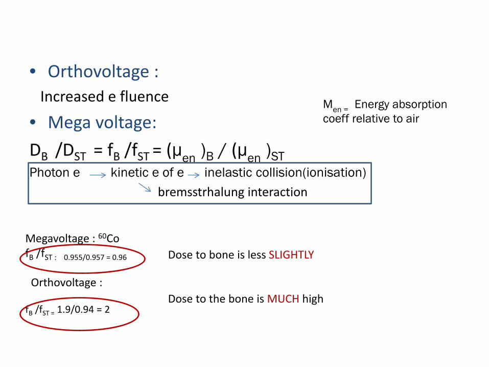
• Orthovoltage : Increased e fluence
• Mega voltage: DB /DST = fB /fST = (μen )B / (μen )ST Photon e kinetic e of e inelastic collision(ionisation) bremsstrhalung interaction
Μen = Energy absorption coeff relative to air
Megavoltage : 60Co fB /fST : 0.955/0.957 = 0.96 Orthovoltage : fB /fST = 1.9/0.94 = 2
Dose to bone is less SLIGHTLY Dose to the bone is MUCH high
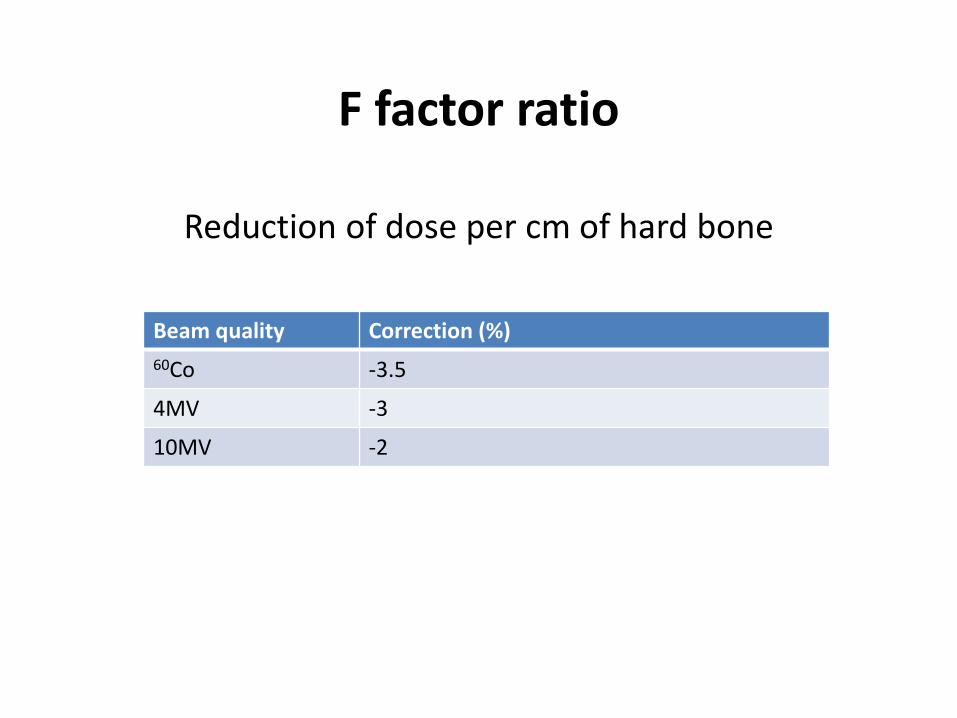
F factor ratio
Reduction of dose per cm of hard bone
Beam quality Correction (%) 60Co -3.5
4MV -3
10MV -2
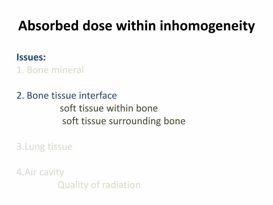
Absorbed dose within inhomogeneity
Issues: 1. Bone mineral
2. Bone tissue interface soft tissue within bone soft tissue surrounding bone 3.Lung tissue 4.Air cavity Quality of radiation
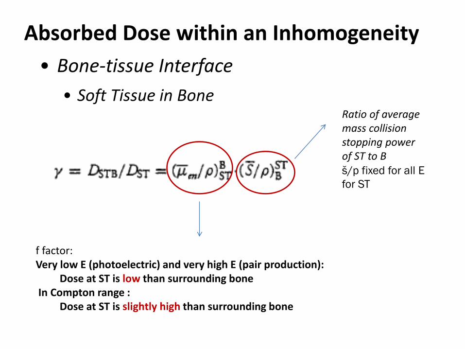
Absorbed Dose within an Inhomogeneity • Bone-tissue Interface
• Soft Tissue in Bone
Ratio of average mass collision stopping power of ST to B š/р fixed for all E for ST
f factor: Very low E (photoelectric) and very high E (pair production): Dose at ST is low than surrounding bone In Compton range : Dose at ST is slightly high than surrounding bone
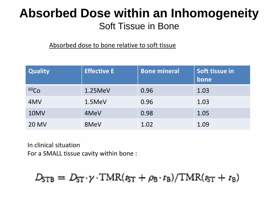
Absorbed Dose within an Inhomogeneity Soft Tissue in Bone
Quality Effective E Bone mineral Soft tissue in bone
60Co 1.25MeV 0.96 1.03
4MV 1.5MeV 0.96 1.03
10MV 4MeV 0.98 1.05
20 MV 8MeV 1.02 1.09
Absorbed dose to bone relative to soft tissue
In clinical situation For a SMALL tissue cavity within bone :
Absorbed dose within inhomogeneity
Issues: 1. Bone mineral
2. Bone tissue interface soft tissue within bone soft tissue surrounding bone 3.Lung tissue 4.Air cavity Quality of radiation
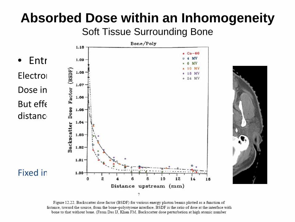
Absorbed Dose within an Inhomogeneity Soft Tissue Surrounding Bone
• Entrance site: Electron backscatter Dose in ST > B But effect vanishes in short distance upstream Fixed in all energy range
Absorbed Dose within an Inhomogeneity Soft Tissue Surrounding Bone
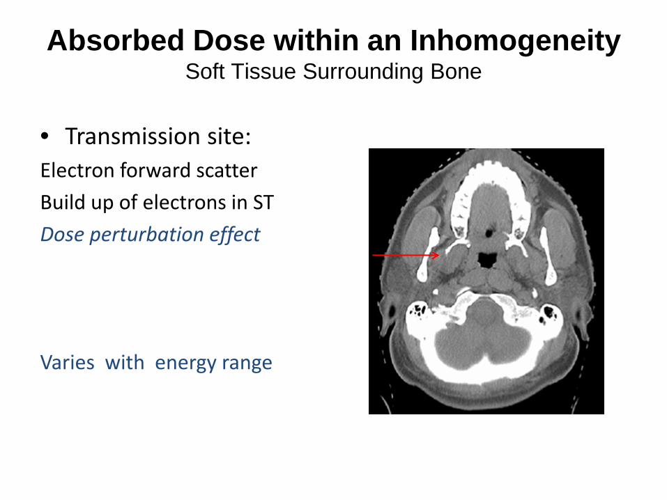
• Transmission site: Electron forward scatter Build up of electrons in ST Dose perturbation effect Varies with energy range
Absorbed Dose within an Inhomogeneity Soft Tissue Surrounding Bone
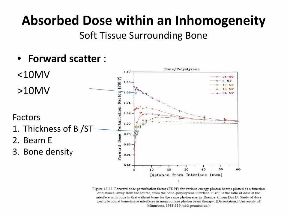
• Forward scatter : <10MV >10MV
Factors 1. Thickness of B /ST 2. Beam E 3. Bone density
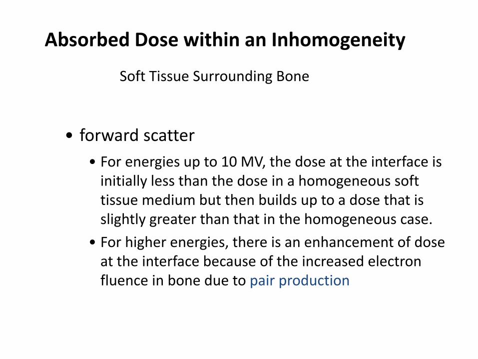
• forward scatter
• For energies up to 10 MV, the dose at the interface is initially less than the dose in a homogeneous soft tissue medium but then builds up to a dose that is slightly greater than that in the homogeneous case.
• For higher energies, there is an enhancement of dose at the interface because of the increased electron fluence in bone due to pair production
Absorbed Dose within an Inhomogeneity Soft Tissue Surrounding Bone
Absorbed Dose within an Inhomogeneity
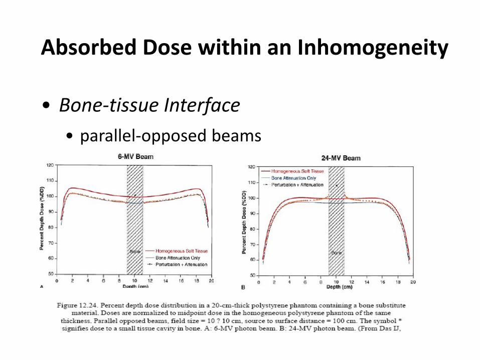
• Bone-tissue Interface • parallel-opposed beams
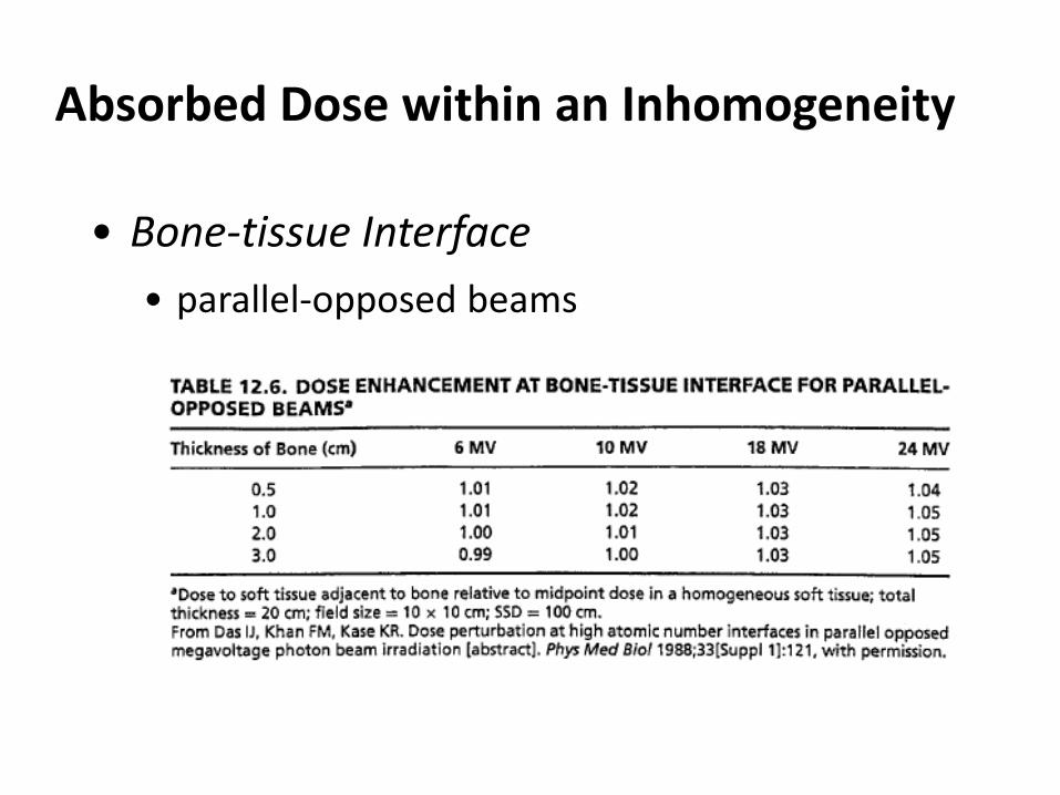
Absorbed Dose within an Inhomogeneity
• Bone-tissue Interface • parallel-opposed beams
Absorbed dose within inhomogeneity
Issues: 1. Bone mineral
2. Bone tissue interface soft tissue within bone soft tissue surrounding bone 3.Lung tissue 4.Air cavity Quality of radiation
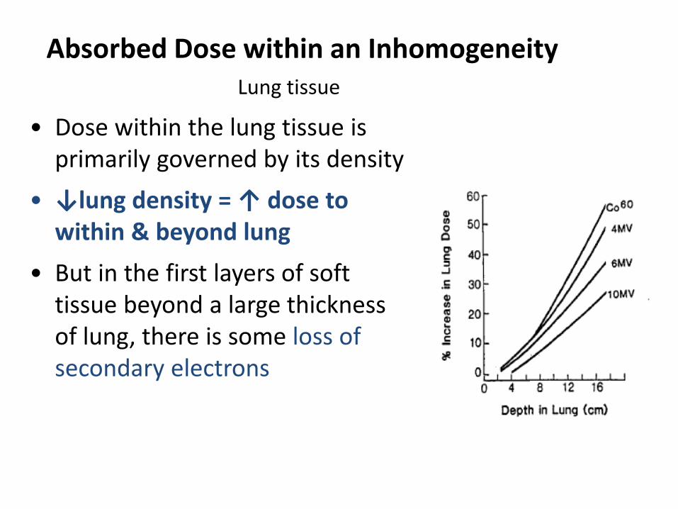
Absorbed Dose within an Inhomogeneity Lung tissue
• Dose within the lung tissue is primarily governed by its density
• ↓lung density = ↑ dose to within & beyond lung
• But in the first layers of soft tissue beyond a large thickness of lung, there is some loss of secondary electrons
Absorbed Dose within an Inhomogeneity Lung Tissue
• Increased no of e travel outside the geometric boundary
↑ lateral scattering of e/ ↓dose in beam axis
dose profile to become less sharp
• The effect is significant for • small field sizes ( < 6 x 6 cm ) • higher energies ( >6 MV )
Absorbed dose within inhomogeneity
Issues: 1. Bone mineral
2. Bone tissue interface soft tissue within bone soft tissue surrounding bone 3.Lung tissue 4.Air cavity Quality of radiation
Absorbed Dose within an Inhomogeneity
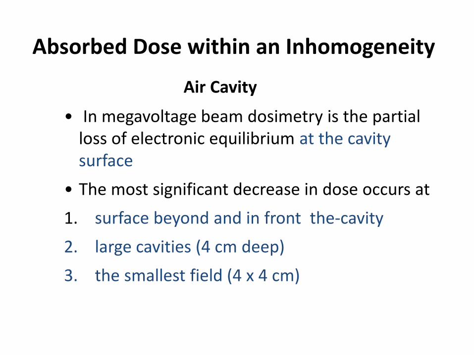
Air Cavity
• In megavoltage beam dosimetry is the partial loss of electronic equilibrium at the cavity surface
• The most significant decrease in dose occurs at 1. surface beyond and in front the-cavity 2. large cavities (4 cm deep) 3. the smallest field (4 x 4 cm)
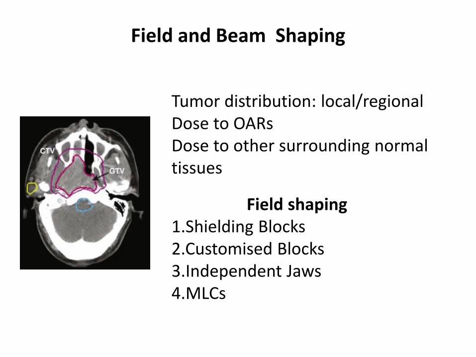
Field and Beam Shaping
Tumor distribution: local/regional Dose to OARs Dose to other surrounding normal tissues
Field shaping 1.Shielding Blocks 2.Customised Blocks 3.Independent Jaws 4.MLCs
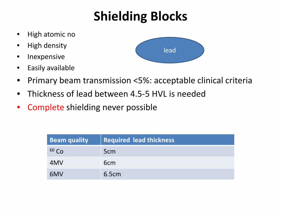
Shielding Blocks • High atomic no • High density • Inexpensive • Easily available
• Primary beam transmission <5%: acceptable clinical criteria • Thickness of lead between 4.5-5 HVL is needed • Complete shielding never possible
Beam quality Required lead thickness 60 Co 5cm
4MV 6cm
6MV 6.5cm
lead
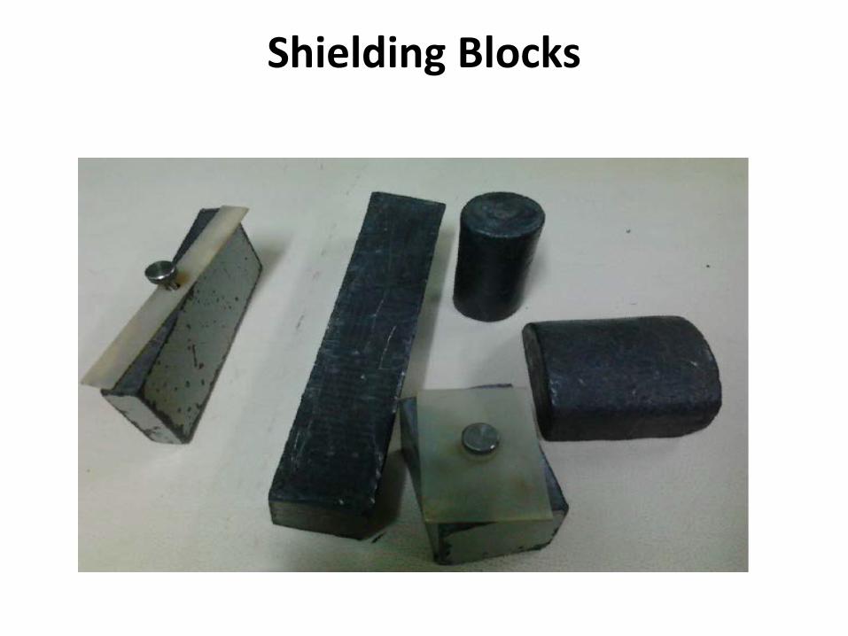
Shielding Blocks
Shielding Blocks
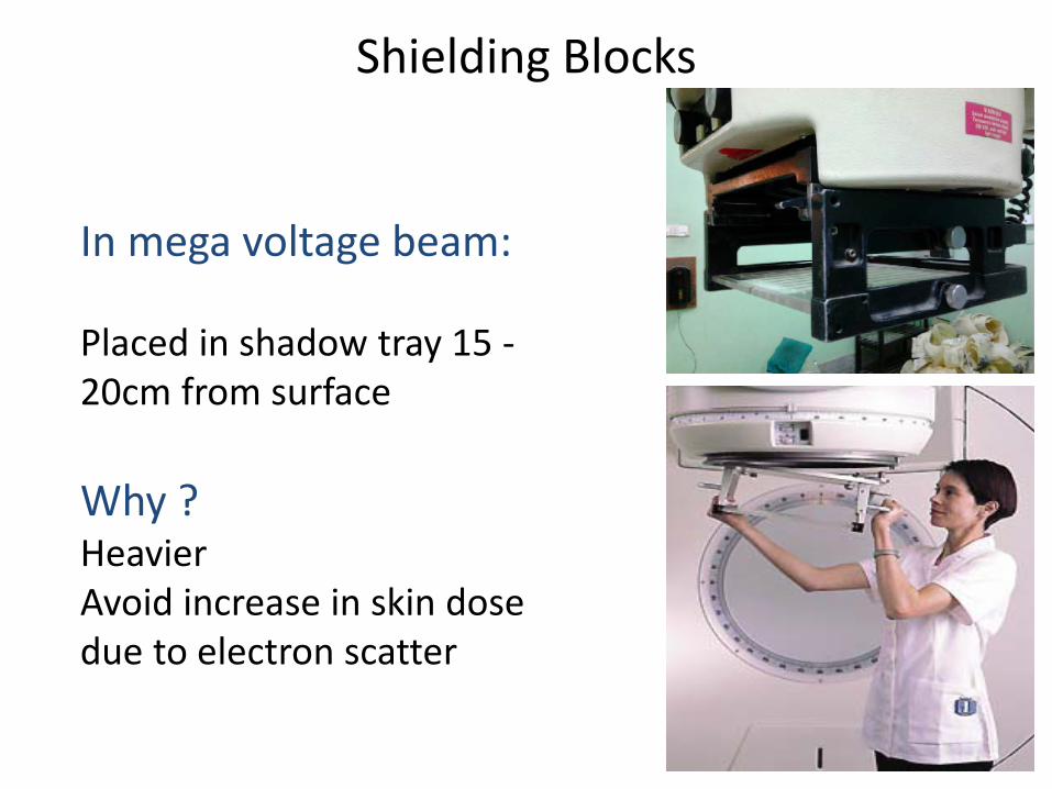
In mega voltage beam: Placed in shadow tray 15 -20cm from surface Why ? Heavier Avoid increase in skin dose due to electron scatter
Customised Blocks Lipowitz material (cerrobend) Features : • 50% bismuth, 26.7% lead,13.3% Tin, 10% Cadmium • Density 9.4gm/cm3 (83% of lead) • Low melting point(70o C) • At normal temperature harder than lead • Thickness : 1.21(density ratio)× lead thickness
Additional accessories Styrofoam Styrofoam cutter
Customised Blocks
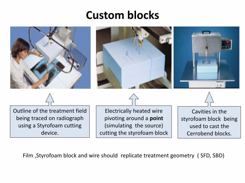
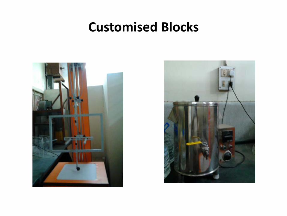
Custom blocks
Film ,Styrofoam block and wire should replicate treatment geometry ( SFD, SBD)
Outline of the treatment field being traced on radiograph using a Styrofoam cutting
device.
Electrically heated wire pivoting around a point (simulating the source)
cutting the styrofoam block
Cavities in the styrofoam block being
used to cast the Cerrobend blocks.
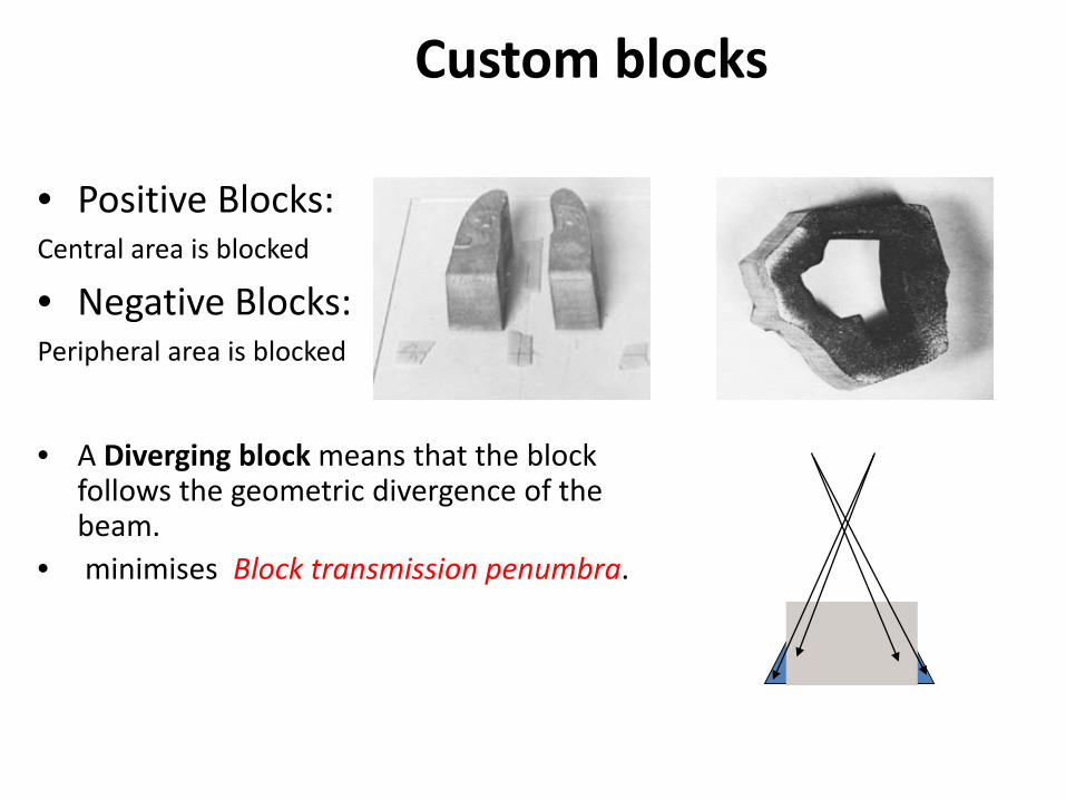
Custom blocks
• Positive Blocks: Central area is blocked
• Negative Blocks: Peripheral area is blocked
• A Diverging block means that the block
follows the geometric divergence of the beam.
• minimises Block transmission penumbra.
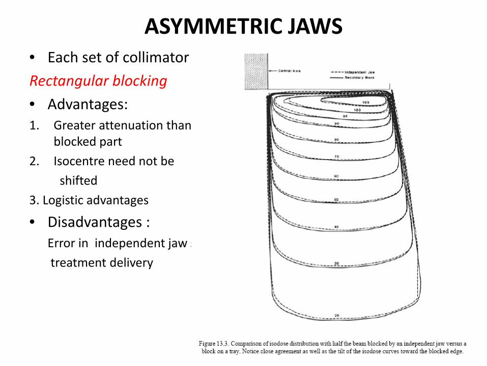
ASYMMETRIC JAWS • Each set of collimator jaws open and close independently Rectangular blocking • Advantages: 1. Greater attenuation than alloy shield less dose to
blocked part 2. Isocentre need not be shifted 3. Logistic advantages
• Disadvantages : Error in independent jaw setting during treatment delivery
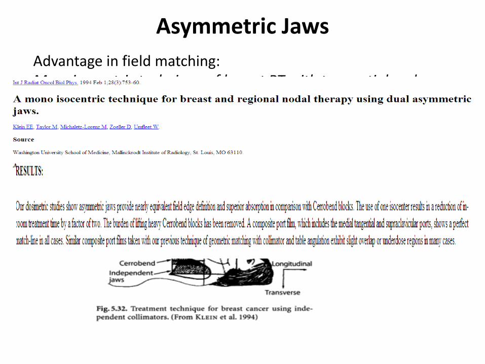
Asymmetric Jaws Advantage in field matching: Monoisocentric technique of breast RT with tangential and nodal RT
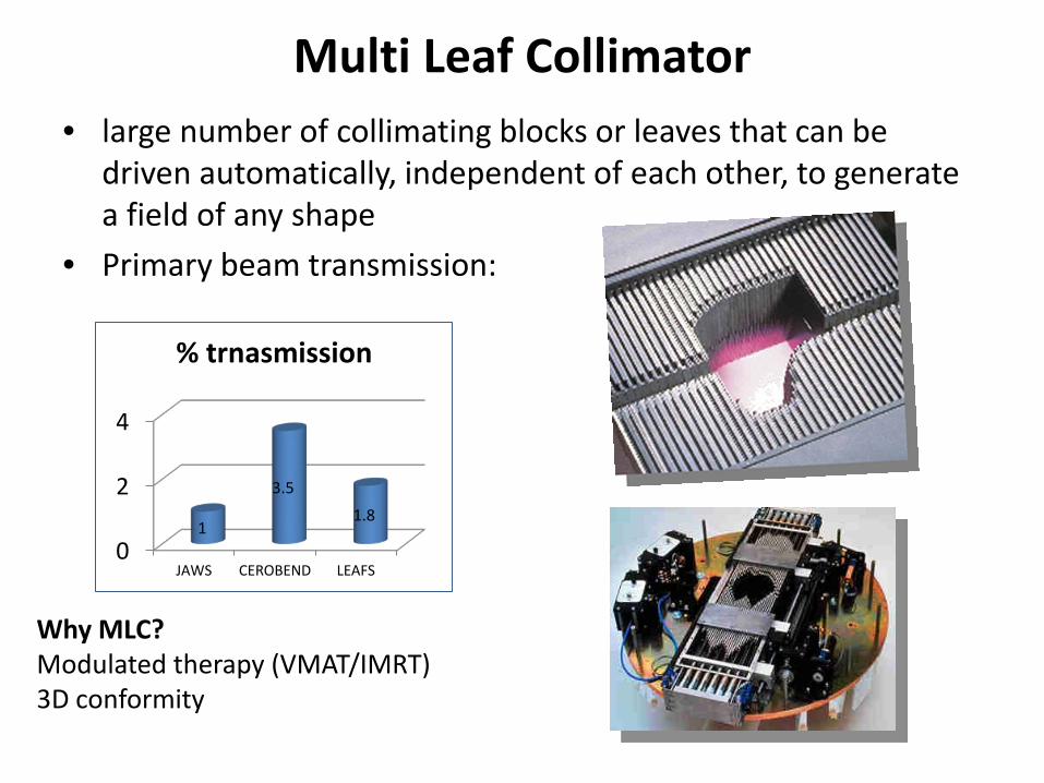
Multi Leaf Collimator • large number of collimating blocks or leaves that can be
driven automatically, independent of each other, to generate a field of any shape
• Primary beam transmission:
0
2
4
JAWS CEROBEND LEAFS
1
3.5 1.8
% trnasmission
Why MLC? Modulated therapy (VMAT/IMRT) 3D conformity
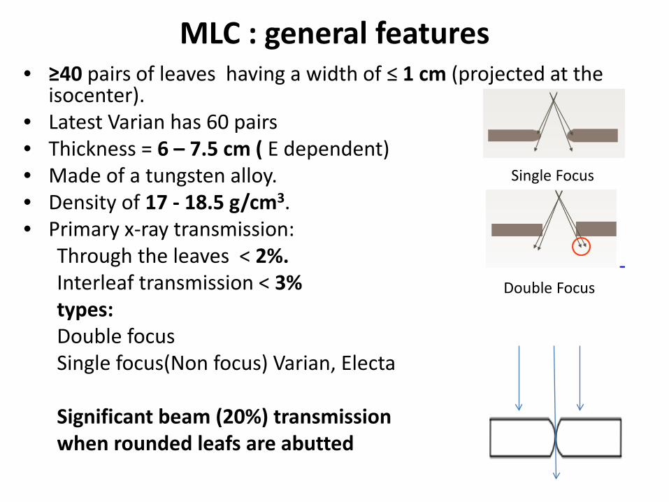
MLC : general features • ≥40 pairs of leaves having a width of ≤ 1 cm (projected at the
isocenter). • Latest Varian has 60 pairs • Thickness = 6 – 7.5 cm ( E dependent) • Made of a tungsten alloy. • Density of 17 - 18.5 g/cm3. • Primary x-ray transmission:
Through the leaves < 2%. Interleaf transmission < 3% types: Double focus Single focus(Non focus) Varian, Electa Significant beam (20%) transmission when rounded leafs are abutted
Single Focus
Double Focus
MLC
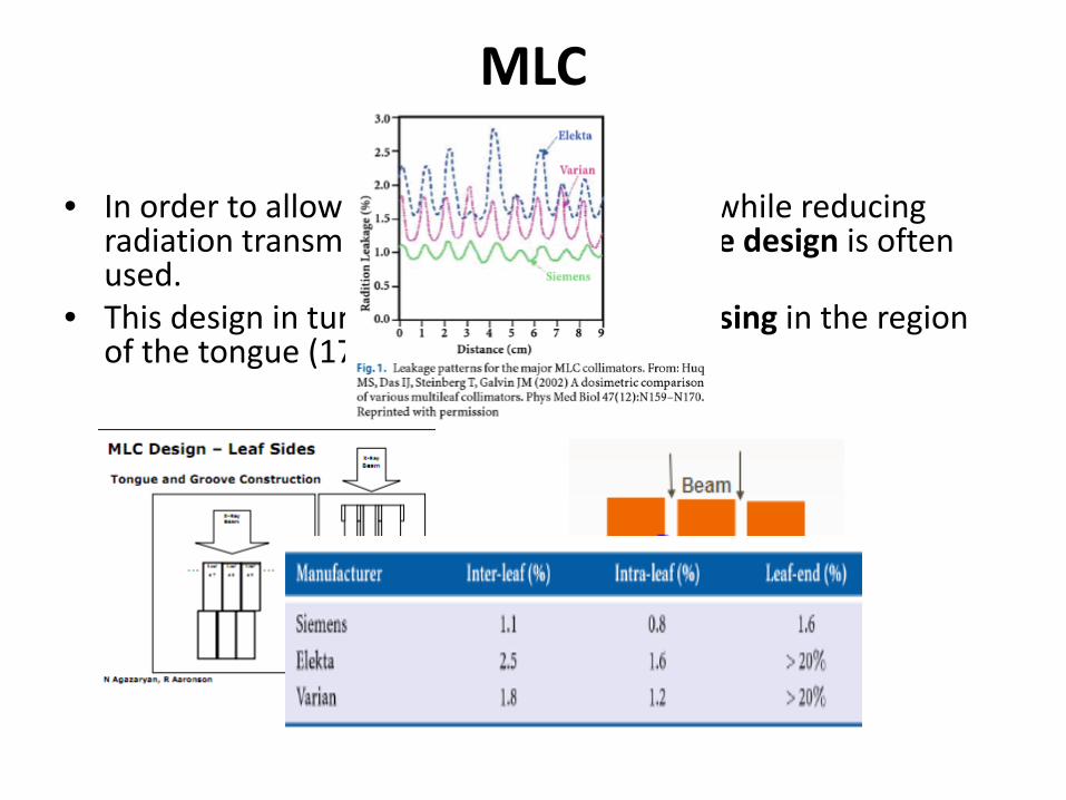
• In order to allow fast interleaf movement, while reducing radiation transmission a tongue and groove design is often used.
• This design in turn leads to some under dosing in the region of the tongue (17 – 25%).
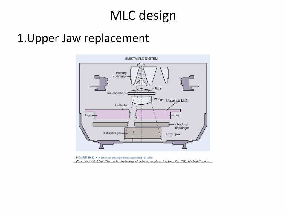
MLC design 1.Upper Jaw replacement
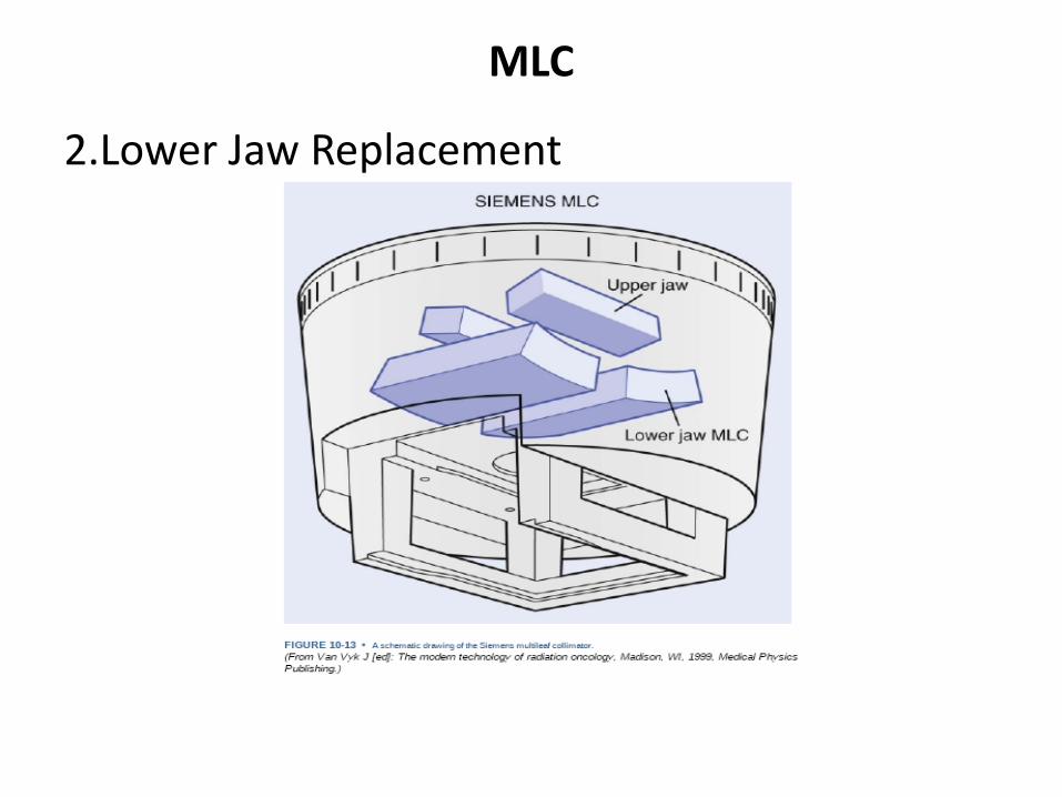
MLC
2.Lower Jaw Replacement
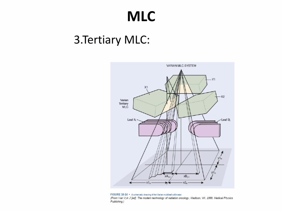
MLC 3.Tertiary MLC:
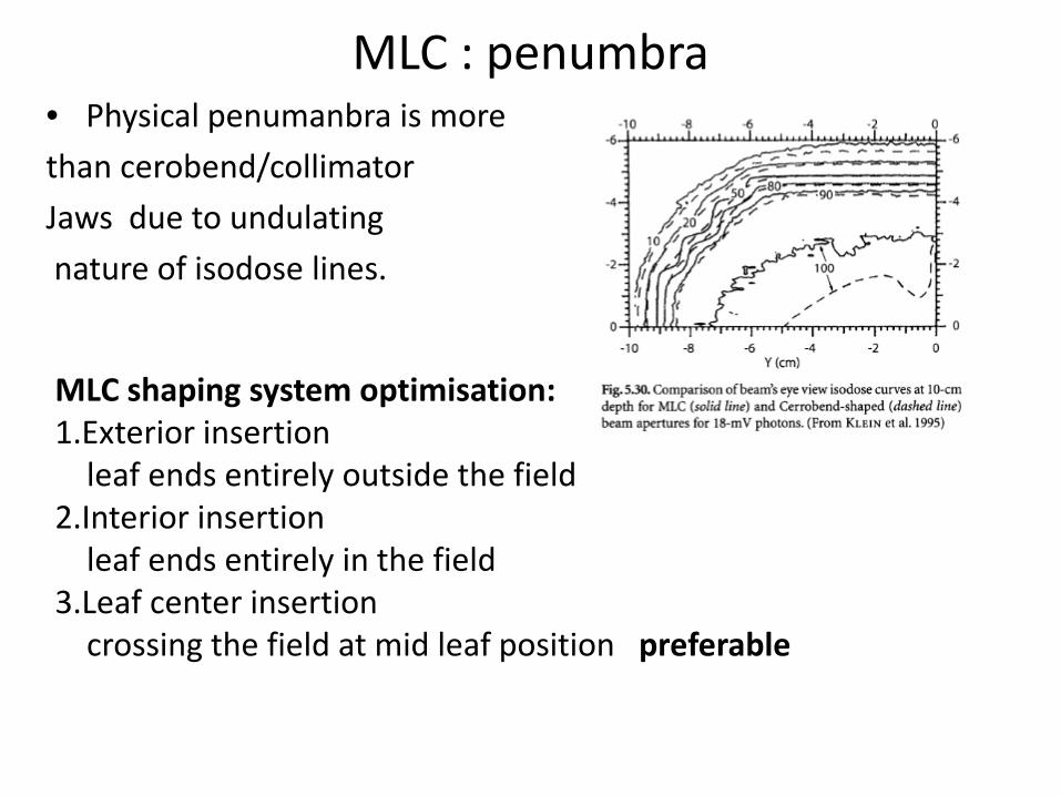
MLC : penumbra • Physical penumanbra is more than cerobend/collimator Jaws due to undulating nature of isodose lines.
MLC shaping system optimisation: 1.Exterior insertion leaf ends entirely outside the field 2.Interior insertion leaf ends entirely in the field 3.Leaf center insertion crossing the field at mid leaf position preferable
MLC
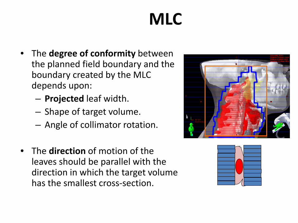
• The degree of conformity between the planned field boundary and the boundary created by the MLC depends upon: – Projected leaf width. – Shape of target volume. – Angle of collimator rotation.
• The direction of motion of the
leaves should be parallel with the direction in which the target volume has the smallest cross-section.
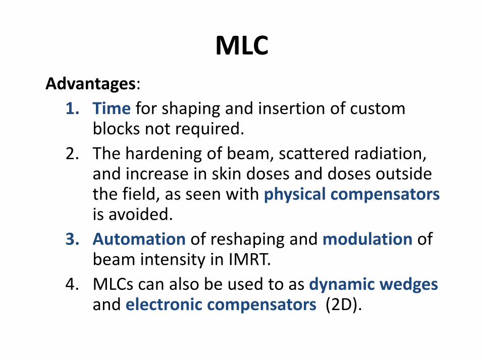
MLC Advantages:
1. Time for shaping and insertion of custom blocks not required.
2. The hardening of beam, scattered radiation, and increase in skin doses and doses outside the field, as seen with physical compensators is avoided.
3. Automation of reshaping and modulation of beam intensity in IMRT.
4. MLCs can also be used to as dynamic wedges and electronic compensators (2D).
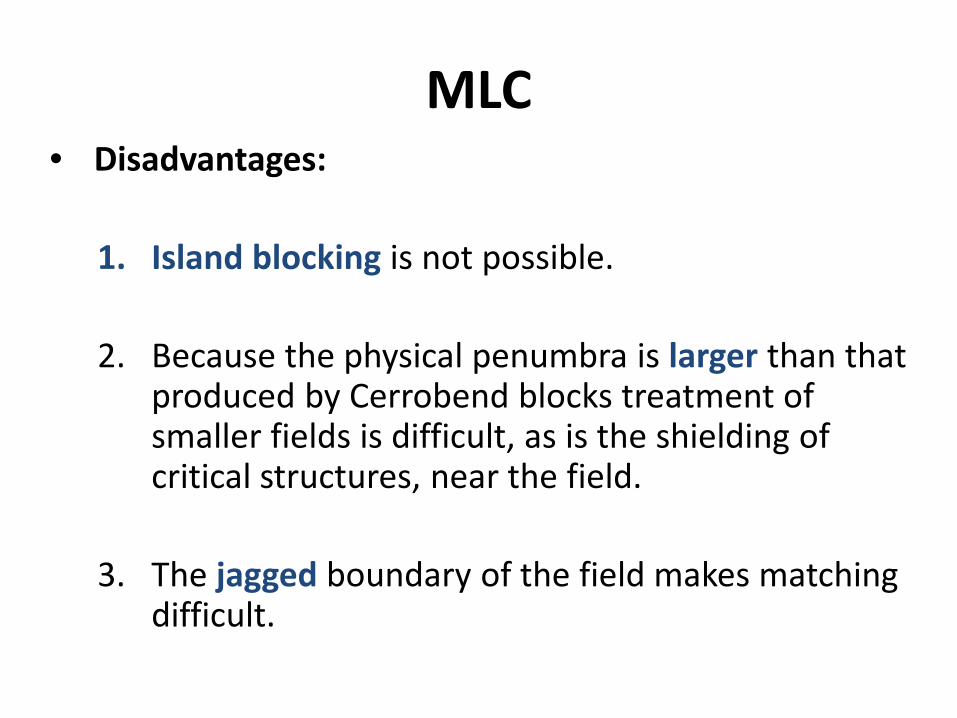
MLC • Disadvantages:
1. Island blocking is not possible.
2. Because the physical penumbra is larger than that produced by Cerrobend blocks treatment of smaller fields is difficult, as is the shielding of critical structures, near the field.
3. The jagged boundary of the field makes matching difficult.


![SSD - ESOS LAB€¦ · SSD . 1 SSD Block Diagram 3.2 SSD NAND HDD . . SSD FTL . FTL NAND out-of-place update address mapping . Gabage Collection, Wear-leveling . 4. 4.1 SSD . Disksim[8]](https://img.pdfslide.net/doc/110x75/5ea6b67696cb1838a26c1ab1/ssd-esos-ssd-1-ssd-block-diagram-32-ssd-nand-hdd-ssd-ftl-ftl-nand-out-of-place.jpg)