Embed Size (px)
Citation preview
The
MF/HFRadio GuideFor the Long Range Certificate ofCompetency in Radiotelephony
TRG-6Version 3, April 2014

Stores Item: TRG-06 – April 2014Note: This printed document is deemed correct only for date of issue.
For the most current version refer to the Learning Zone.
© Copyright RNLI 2014.No part of this publication may be produced or transmitted in any form, or by any means, electronic or
mechanical, including photocopying, recording, or by any information storage or retrieval system, withoutpermission from the RNLI. Although every effort is taken to ensure the content of this publication is accurate,
the RNLI cannot take responsibility for any incorrect action taken, or not, due to errors or omissions.
3
Activity 6.2 | Operational CommunicationVersion 3, April 2014
Content
Aim and Objectives ................................... 5
An Introduction to GMDSS ........................ 6 Global Maritime Distress and Safety System ....................................... 6 Digital Selective Calling ........................ 6 EPIRBs ................................................. 7 SARTs ................................................... 7
Frequencies ............................................... 9 The Concept of Frequencies ................ 9 Frequency and Wave length ................. 6 Frequency Designations ..................... 10 Bandwidth ........................................... 10
Modulation ............................................... 10 Frequency Modulation, (FM) ............... 10 Amplitude Modulation, (AM) ............... 11 Double Side-Band, (DSB) ................... 11 Single Side-Band, (SSB) .................... 11
Propagation of Radio Signals .................. 12 Very High Frequencies, (VHF) ............ 12 Medium Frequencies, (MF) ................. 12 High Frequencies, (HF) ...................... 12
The Earth’s Atmosphere ..................... 13 The Troposphere ................................ 13 The Stratosphere ................................ 13 The Ionosphere ................................... 13
Simplex and Duplex Channels ................ 14 Simplex ............................................... 14 Duplex ................................................. 14 Semi-Duplex ....................................... 14
Sea Areas ................................................ 15
Digital Selective Calling ........................... 16 Distress Alerts ..................................... 16 The ‘Undesignated’ Alert ..................... 16 The ‘Designated’ Alert ........................ 17 The Response from a Vessel .............. 18 The Response for Sea Area A1 .......... 18 The Response for Sea Area A2 .......... 19 The Response for Sea Areas A3 and A4 ................................................. 19 The Response from the Shore ............ 19
DSC Urgency and Safety Alerts .......... 19 DSC Routine Alerts ............................ 19 DSC Testing ........................................ 19 Internal Tests ....................................... 19 External Tests ..................................... 19
EPIRBs .................................................... 20 COSPAS-SARSAT .............................. 20 Registering EPIRBs ............................ 21 Testing EPIRBs ................................... 21
SARTS ..................................................... 22
Maritime Safety Information (NAVTEX) ... 24
Antennae/Aerials ..................................... 25 Antenna Tuning Unit, (ATU) ................ 26 Emergency Antenna ........................... 26 Antenna Maintenance ......................... 26
Batteries .................................................. 27 Types of Batteries ............................... 27
Maritime Mobile Service Identity (MMSI)numbers................................................... 29
Distress .................................................... 30 Distress Call Example ......................... 30 Distress Acknowledgement ................. 31 Distress Relays ................................... 32 Control of Communications ................ 32 Imposing Radio Silence ...................... 32 Cancelling Radio Silence ................... 32
Urgency ................................................... 33 Medical Advice .................................... 33
Safety ..................................................... 34
Regulations.............................................. 35 Radio Licences ................................... 35 The Equipment’s Licence .................... 35 The Ship’s Licence .............................. 35 The Operator’s Licence ...................... 35 SafetyRadioCertificateSurvey .......... 35 Ship’s Licence Inspection ................... 35 Breach of Radio Regulations .............. 35 Master’s (Cox/Helm’s) Authority ......... 35
Activity 6.2 | Operational Communication
4
Version 3, April 2014
Secrecy of Correspondence .................... 36 Test Transmissions ............................. 36 Radio Equipment Tests ....................... 36 Transmission Rules, (Avoidance of Interference) ................. 36 Time Keeping ...................................... 36 IdentificationofStations .......................... 37 Coast Stations .................................... 37 Ship Stations ....................................... 37 Radio Watch ....................................... 37 GMDSS Radio Logbook ..................... 37 Documents to be Carried .................... 38 Order of Priority of Communications ... 38 Allowable Transmissions in UK ........... 38 Harbours and Inland Waterways ......... 39
Appendix 1: Glossary ............................. 39Appendix 2 : Specimen Radio Log ......... 42Appendix 3: The Phonetic Alphabet ....... 43Appendix 4: Procedural Words ............... 44
Index ..................................................... 45
5
Activity 6.2 | Operational CommunicationVersion 3, April 2014
Introduction
AimThe aim of this guide is to assist crew members in obtaining The Long Range RadiotelephoneOperator’sCertificate,(LRC). This is the radio operator’s licence required to operate the High, Medium and Very High Frequency (VHF) radio equipmentfittedtoR.N.L.I.Lifeboatsandother vessels that are not required to compulsoryfitGMDSSequipmentunderthe SOLAS convention. These vessels are commonly known as non-compliant vessels.
ObjectivesInordertoobtainthiscertificate,crewmembers will need to pass theoretical and practical tests demonstrating;
• A general knowledge of radio communications within the Maritime Mobile Service.• A detailed practical knowledge of the VHF and MF/HF radio installation and the use of this equipment in practice.• The purpose and use of Digital Selective Calling, (DSC), facilities.• A knowledge of the operational procedures of the GMDSS.• A knowledge of the practical operation of the GMDSS sub-systems and equipment, (as appropriate to ‘non- solas’ vessels). Including;• The Distress, Urgency and Safety communication procedures used in the GMDSS.• The protection of Distress frequencies.• The Maritime Safety Information, (MSI), systems used in the GMDSS.• The Alerting and Locating signals used in the GMDSS.
A knowledge of the regulations, obligatory procedures and practices used in Radiotelephone communications.
Activity 6.2 | Operational Communication
6
Version 3, April 2014
The Global Maritime Distress and Safety System (GMDSS)
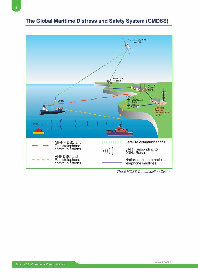
Global Maritime Distress andSafety System (GMDSS)On the 1st February 1999, the International Maritime Organisation, (IMO), implemented a new, worldwide network of emergency communications for vessels at sea. This new system is known as the Global Maritime Distress and Safety System, (or GMDSS).
The basic concept of the GMDSS is that the search and rescue authorities, as well as shipping in the immediate area, are rapidly alerted to a distress incident so that they can assist in a coordinated search and rescue operation with the minimum of delay. The new system also provides for Urgency and Safety communications and the broadcasting of Maritime Safety Information, (NAVTEX).
The introduction of the GMDSS began in February 1992 and was fully in place by 1999. The GMDSS requirements now apply to all vessels over 300 Gross tonnage, passenger vessels carrying morethantwelvepassengersandfishingvessels over 12 meters, these are known as compliant vessels.
Although Lifeboats are not legally required tofitGMDSSequipment,ithasbeeninstalled for operational reasons. In order for crew members to operate this they must hold a minumum of a Long Range Certificate,(LRC),whichentitlestheholderto operate both MF/HF and VHF equipment onanyvesselnotsubjecttocompulsory-fitunder the SOLAS convention.
Digital Selective CallingThe cornerstone of the GMDSS is Digital Selective Calling, (usually referred to as DSC).
Before the introduction of Digital Selective Calling, a radio operator would have to call another radio station using an R/T Calling frequency, (typically Channel 16 VHF or 2182 kHz MF). This method of contacting another station relied on the station being called maintaining a listening watch on the relevant calling frequency.
But by using DSC, a radio operator can now send a digital signal, (known as an Alert), to a selected station prior to the voice transmission. The DSC’s digital signal takes only seconds to transmit, but contains the transmitting station’s identity and can include position. This Alert will act in a similar way as a telephone pager, automatically sounding an alarm on the called station’s DSC receiver.
Under the new SOLAS Agreement, GMDSS compulsory-fit ships must be able to:
• Transmit Ship-to-Shore Alerts by two separate and independent systems, each using a different radio-communication service.• Receive Shore-to-Ship Distress Alerts.• Transmit and receive Ship-to-Ship Distress Alerts and Bridge-to-Bridge communications.• Transmit and receive SAR Co-ordinating Communications and On-Scene Communications.• Transmit and receive homing or locating signals.• Transmit and receive Maritime Safety Information.• Transmit and receive general shore-based radio communications.
7
Activity 6.2 | Operational CommunicationVersion 3, April 2014
The Global Maritime Distress and Safety System (GMDSS)
If the Alert is sent to ‘All Stations’, (as in a Distress Alert), then all DSC receivers within range will sound an alarm and store the details of the Alert in the receiver’s memory. After hearing an alarm, radio operators will carefully monitor the radiotelephone knowing that a voice message is about to be transmitted that directly affects them.
An Alert can also be directed at a single, selected station. This is achieved by giving every radio station a unique code number, known as its Maritime Mobile Service Identity number, (or MMSI). An MMSI number works in the same way as a telephone number. By including a station’s MMSI number in the Alert, only that station’s receiver will sound an alarm. All other DSC receivers within range will remain silent.
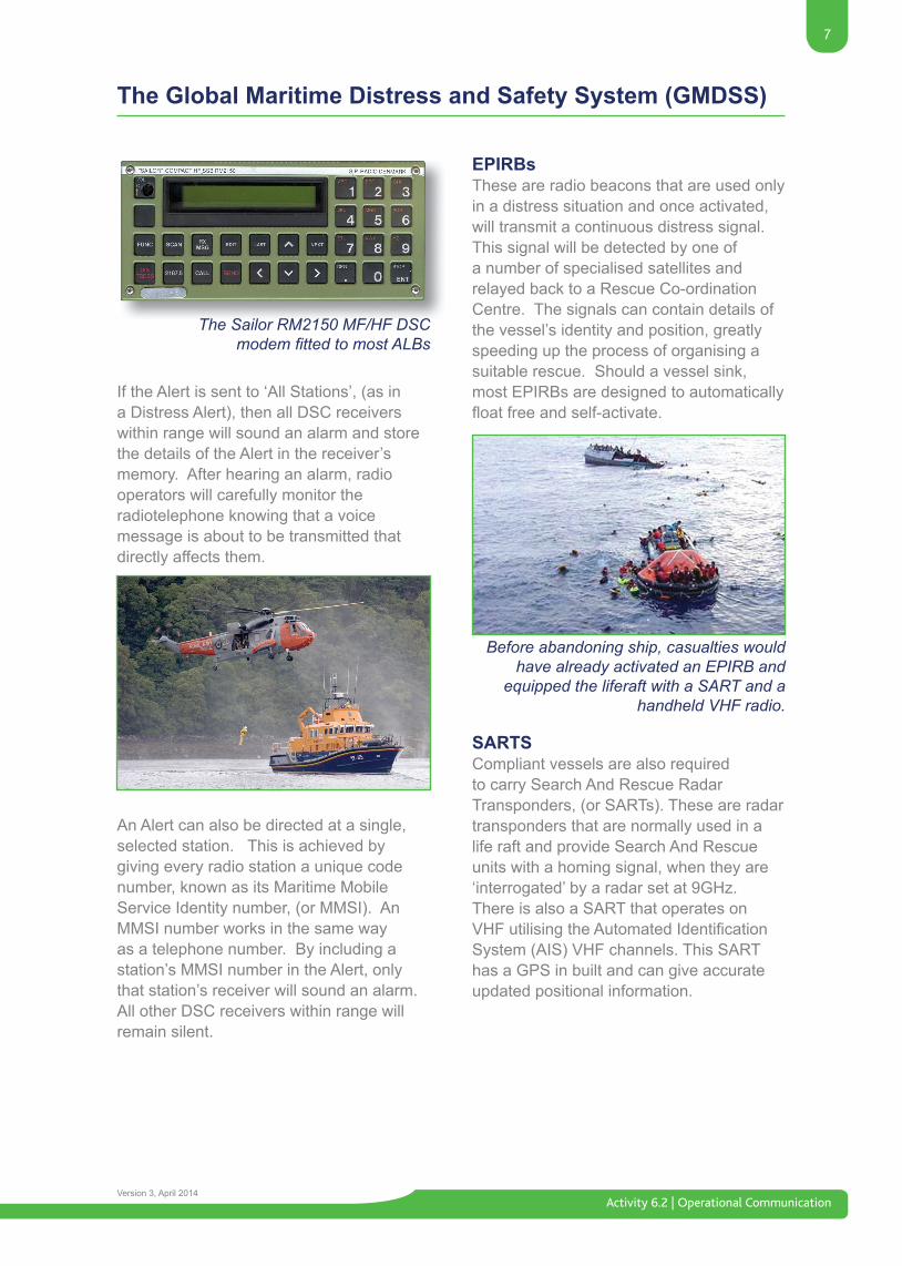
The Sailor RM2150 MF/HF DSC modem fitted to ALBs.
The Sailor RM2150 MF/HF DSCmodem fitted to most ALBs
Before abandoning ship, casualties would have already activated an EPIRB and
equipped the liferaft with a SART and a handheld VHF radio.
EPIRBsThese are radio beacons that are used only in a distress situation and once activated, will transmit a continuous distress signal. This signal will be detected by one of a number of specialised satellites and relayed back to a Rescue Co-ordination Centre. The signals can contain details of the vessel’s identity and position, greatly speeding up the process of organising a suitable rescue. Should a vessel sink, most EPIRBs are designed to automatically floatfreeandself-activate.
SARTSCompliant vessels are also required to carry Search And Rescue Radar Transponders, (or SARTs). These are radar transponders that are normally used in a life raft and provide Search And Rescue units with a homing signal, when they are ‘interrogated’ by a radar set at 9GHz.There is also a SART that operates on VHFutilisingtheAutomatedIdentificationSystem (AIS) VHF channels. This SART has a GPS in built and can give accurate updated positional information.
Activity 6.2 | Operational Communication
8
Version 3, April 2014
The Global Maritime Distress and Safety System (GMDSS)
The GMDSS Comunication System
9
Activity 6.2 | Operational CommunicationVersion 3, April 2014
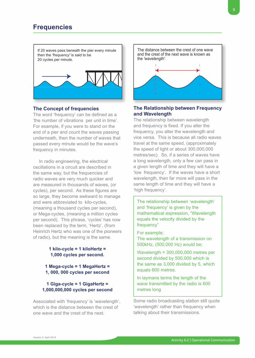
The Relationship between Frequency and WavelengthThe relationship between wavelengthandfrequencyisfixed.Ifyoualterthefrequency, you alter the wavelength and vice versa. This is because all radio waves travel at the same speed, (approximately the speed of light or about 300,000,000 metres/sec). So, if a series of waves have a long wavelength, only a few can pass in a given length of time and they will have a ‘low frequency’. If the waves have a short wavelength, then far more will pass in the same length of time and they will have a ‘high frequency’.
Some radio broadcasting station still quote ‘wavelength’ rather than frequency when talking about their transmissions.
Frequencies
The Concept of frequenciesTheword‘frequency’canbedefinedasa‘the number of vibrations per unit in time’. For example, if you were to stand on the end of a pier and count the waves passing underneath, then the number of waves that passed every minute would be the wave’s frequency in minutes.
In radio engineering, the electrical oscillations in a circuit are described in the same way, but the frequencies of radio waves are very much quicker and are measured in thousands of waves, (or cycles),persecond.Asthesefiguresareso large, they become awkward to manage and were abbreviated to kilo-cycles, (meaning a thousand cycles per second), or Mega-cycles, (meaning a million cycles per second). This phrase, ‘cycles’ has now been replaced by the term, ‘Hertz’, (from Heinrich Hertz who was one of the pioneers of radio), but the meaning is the same.
1 kilo-cycle = 1 kiloHertz = 1,000 cycles per second.
1 Mega-cycle = 1 MegaHertz =1, 000, 000 cycles per second
1 Giga-cycle = 1 GigaHertz = 1,000,000,000 cycles per second
Associated with ‘frequency’ is ‘wavelength’, which is the distance between the crest of one wave and the crest of the next.
The relationship between ‘wavelength’ and ‘frequency’ is given by the mathematical expression, “Wavelength equals the velocity divided by the frequency”
For example;The wavelength of a transmission on 500kHz, (500,000 Hz) would be;
Wavelength = 300,000,000 metres per second divided by 500,000 which is the same as 3,000 divided by 5, which equals 600 metres.
In laymans terms the length of the wave transmitted by the radio is 600 metres long
Activity 6.2 | Operational Communication
10
Version 3, April 2014
Frequencies and Modulation
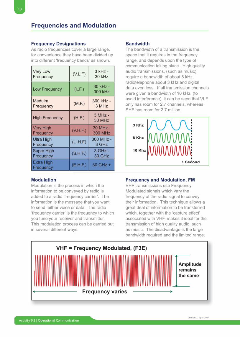
Frequency DesignationsAs radio frequencies cover a large range, for convenience they have been divided up into different ‘frequency bands’ as shown.
BandwidthThe bandwidth of a transmission is the space that it requires in the frequency range, and depends upon the type of communication taking place. High quality audio transmissions, (such as music), require a bandwidth of about 8 kHz, radiotelephone about 3 kHz and digital data even less. If all transmission channels were given a bandwidth of 10 kHz, (to avoid interference), it can be seen that VLF only has room for 2.7 channels, whereas SHF has room for 2.7 million.
ModulationModulation is the process in which the information to be conveyed by radio is added to a radio ‘frequency carrier’. The information is the message that you want to send, either voice or data. The radio ‘frequency carrier’ is the frequency to which you tune your receiver and transmitter. This modulation process can be carried out in several different ways.
Very LowFrequency (V.L.F) 3 kHz -
30 kHz
Low Frequency (l..F.) 30 kHz - 300 kHz
MeduimFrequency (M.F.) 300 kHz -
3 MHz
High Frequency (H.F.) 3 MHz -30 MHz
Very HighFrequency (V.H.F.) 30 MHz -
300 MHzUltra HighFrequency (U.H.F) 300 MHz -
3 GHzSuper HighFrequency (S.H.F.) 3 GHz -
30 GHzExtra HighFrequency (E.H.F.) 30 GHz +
Frequency and Modulation, FMVHF transmissions use Frequency Modulated signals which vary the frequency of the radio signal to convey their information. This technique allows a great deal of information to be transferred which, together with the ‘capture effect’ associated with VHF, makes it ideal for the transmission of high quality audio, such as music. The disadvantage is the large bandwidth required and the limited range.
VHF = Frequency Modulated, (F3E)
Frequency varies
Amplituderemains the same
3 Khz
1 Second
8 Khz
10 Khz
11
Activity 6.2 | Operational CommunicationVersion 3, April 2014
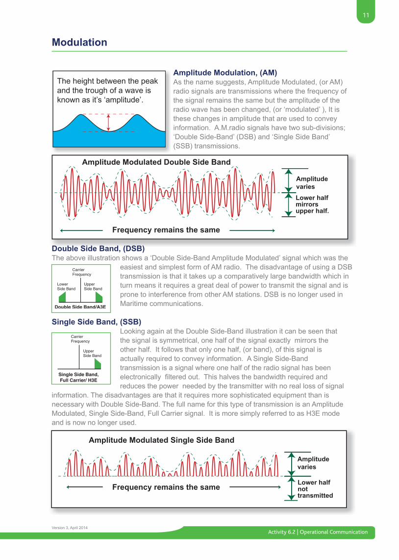
Amplitude Modulation, (AM)As the name suggests, Amplitude Modulated, (or AM) radio signals are transmissions where the frequency of the signal remains the same but the amplitude of the radio wave has been changed, (or ‘modulated’ ), It is these changes in amplitude that are used to convey information. A.M.radio signals have two sub-divisions; ‘Double Side-Band’ (DSB) and ‘Single Side Band’ (SSB) transmissions.
Modulation
The height between the peak and the trough of a wave is known as it’s ‘amplitude’.
Amplitude Modulated Double Side Band
Amplitude Modulated Single Side Band
Frequency remains the same
Frequency remains the same
Amplitudevaries
Amplitudevaries
Lower halfmirrorsupper half.
Lower halfnottransmitted
Double Side Band, (DSB)The above illustration shows a ‘Double Side-Band Amplitude Modulated’ signal which was the
easiest and simplest form of AM radio. The disadvantage of using a DSB transmission is that it takes up a comparatively large bandwidth which in turn means it requires a great deal of power to transmit the signal and is prone to interference from other AM stations. DSB is no longer used in Maritime communications.
Single Side Band, (SSB)Looking again at the Double Side-Band illustration it can be seen thatthe signal is symmetrical, one half of the signal exactly mirrors theother half. It follows that only one half, (or band), of this signal isactually required to convey information. A Single Side-Bandtransmission is a signal where one half of the radio signal has been electronicallyfilteredout.Thishalvesthebandwidthrequiredandreduces the power needed by the transmitter with no real loss of signal
information. The disadvantages are that it requires more sophisticated equipment than is necessary with Double Side-Band. The full name for this type of transmission is an Amplitude Modulated, Single Side-Band, Full Carrier signal. It is more simply referred to as H3E mode and is now no longer used.
Activity 6.2 | Operational Communication
12
Version 3, April 2014
Eventually this drag causes the wave to collapse, a process know as
‘attenuation’.
The magnetic pull of the earth ‘drags’ the bottom of the radio wave causing it to bend producingthe ‘Ground Wave’effect.
MF Propagation
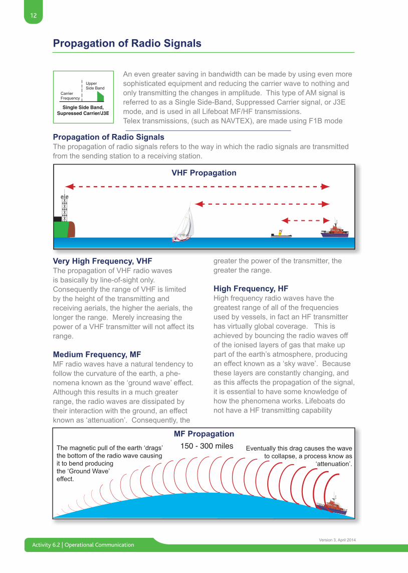
An even greater saving in bandwidth can be made by using even more sophisticated equipment and reducing the carrier wave to nothing and only transmitting the changes in amplitude. This type of AM signal is referred to as a Single Side-Band, Suppressed Carrier signal, or J3E mode, and is used in all Lifeboat MF/HF transmissions.Telex transmissions, (such as NAVTEX), are made using F1B mode
Propagation of Radio Signals
Propagation of Radio SignalsThe propagation of radio signals refers to the way in which the radio signals are transmitted from the sending station to a receiving station.
VHF Propagation
Very High Frequency, VHFThe propagation of VHF radio waves is basically by line-of-sight only. Consequently the range of VHF is limited by the height of the transmitting and receiving aerials, the higher the aerials, the longer the range. Merely increasing the power of a VHF transmitter will not affect its range.
Medium Frequency, MFMF radio waves have a natural tendency to follow the curvature of the earth, a phe-nomena known as the ‘ground wave’ effect. Although this results in a much greater range, the radio waves are dissipated by their interaction with the ground, an effect known as ‘attenuation’. Consequently, the
greater the power of the transmitter, the greater the range.
High Frequency, HFHigh frequency radio waves have the greatest range of all of the frequencies used by vessels, in fact an HF transmitter has virtually global coverage. This is achieved by bouncing the radio waves off of the ionised layers of gas that make up part of the earth’s atmosphere, producing an effect known as a ‘sky wave’. Because these layers are constantly changing, and as this affects the propagation of the signal, it is essential to have some knowledge of how the phenomena works. Lifeboats do not have a HF transmitting capability
13
Activity 6.2 | Operational CommunicationVersion 3, April 2014
The Earth’s Atmosphere
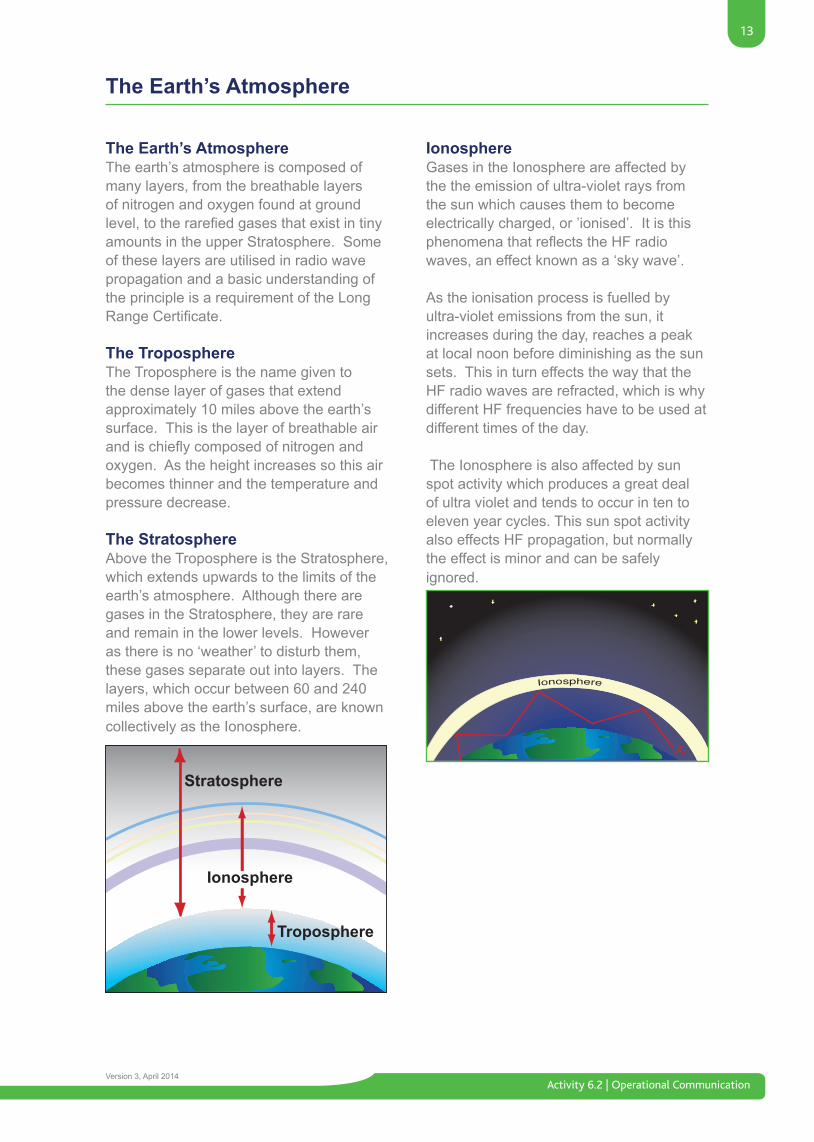
The Earth’s AtmosphereThe earth’s atmosphere is composed of many layers, from the breathable layers of nitrogen and oxygen found at ground level,totherarefiedgasesthatexistintinyamounts in the upper Stratosphere. Some of these layers are utilised in radio wave propagation and a basic understanding of the principle is a requirement of the Long RangeCertificate.
The TroposphereThe Troposphere is the name given to the dense layer of gases that extend approximately 10 miles above the earth’s surface. This is the layer of breathable air andischieflycomposedofnitrogenandoxygen. As the height increases so this air becomes thinner and the temperature and pressure decrease.
The StratosphereAbove the Troposphere is the Stratosphere, which extends upwards to the limits of the earth’s atmosphere. Although there are gases in the Stratosphere, they are rare and remain in the lower levels. However as there is no ‘weather’ to disturb them, these gases separate out into layers. The layers, which occur between 60 and 240 miles above the earth’s surface, are known collectively as the Ionosphere.
IonosphereGases in the Ionosphere are affected by the the emission of ultra-violet rays from the sun which causes them to become electrically charged, or ’ionised’. It is this phenomenathatreflectstheHFradiowaves, an effect known as a ‘sky wave’.
As the ionisation process is fuelled byultra-violet emissions from the sun, it increases during the day, reaches a peak at local noon before diminishing as the sun sets. This in turn effects the way that the HF radio waves are refracted, which is why different HF frequencies have to be used at different times of the day.
The Ionosphere is also affected by sun spot activity which produces a great deal of ultra violet and tends to occur in ten to eleven year cycles. This sun spot activity also effects HF propagation, but normally the effect is minor and can be safely ignored.
Stratosphere
Ionosphere
Troposphere
Activity 6.2 | Operational Communication
14
Version 3, April 2014
Simplex and Duplex Channels
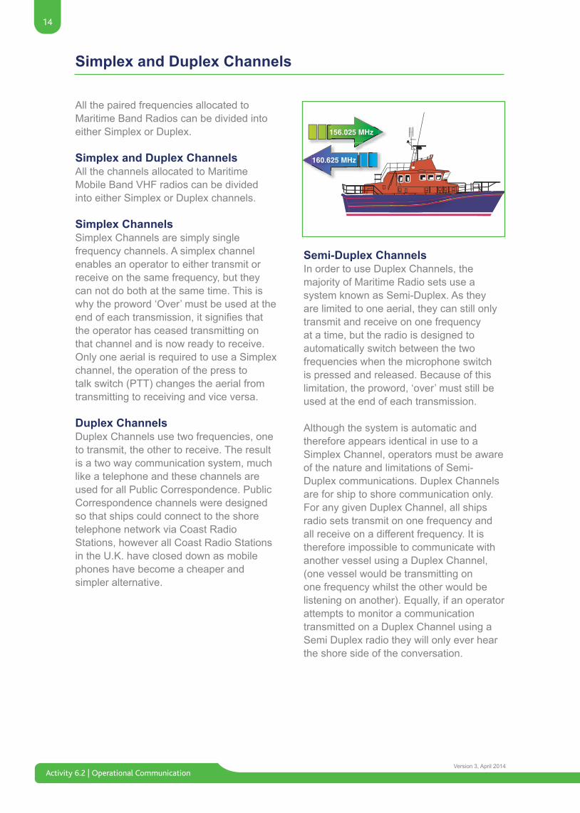
All the paired frequencies allocated to Maritime Band Radios can be divided into either Simplex or Duplex.
Simplex and Duplex ChannelsAll the channels allocated to Maritime Mobile Band VHF radios can be divided into either Simplex or Duplex channels.
Simplex ChannelsSimplex Channels are simply single frequency channels. A simplex channel enables an operator to either transmit or receive on the same frequency, but they can not do both at the same time. This is why the proword ‘Over’ must be used at the endofeachtransmission,itsignifiesthatthe operator has ceased transmitting on that channel and is now ready to receive. Only one aerial is required to use a Simplex channel, the operation of the press to talk switch (PTT) changes the aerial from transmitting to receiving and vice versa.
Duplex ChannelsDuplex Channels use two frequencies, one to transmit, the other to receive. The result is a two way communication system, much like a telephone and these channels are used for all Public Correspondence. Public Correspondence channels were designed so that ships could connect to the shore telephone network via Coast Radio Stations, however all Coast Radio Stations in the U.K. have closed down as mobile phones have become a cheaper and simpler alternative.
Semi-Duplex ChannelsIn order to use Duplex Channels, the majority of Maritime Radio sets use a system known as Semi-Duplex. As they are limited to one aerial, they can still only transmit and receive on one frequency at a time, but the radio is designed to automatically switch between the two frequencies when the microphone switch is pressed and released. Because of this limitation, the proword, ‘over’ must still be used at the end of each transmission.
Although the system is automatic and therefore appears identical in use to a Simplex Channel, operators must be aware of the nature and limitations of Semi-Duplex communications. Duplex Channels are for ship to shore communication only. For any given Duplex Channel, all ships radio sets transmit on one frequency and all receive on a different frequency. It is therefore impossible to communicate with another vessel using a Duplex Channel, (one vessel would be transmitting on one frequency whilst the other would be listening on another). Equally, if an operator attempts to monitor a communication transmitted on a Duplex Channel using a Semi Duplex radio they will only ever hear the shore side of the conversation.
15
Activity 6.2 | Operational CommunicationVersion 3, April 2014
Sea Areas
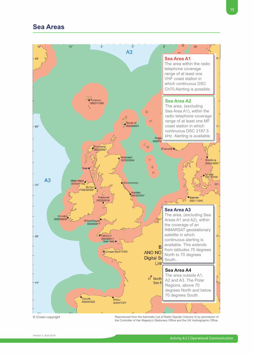
Sea Area A1The area within the radio telephone coverage range of at least one VHF coast station in which continuous DSC Ch70 Alerting is possible.
Sea Area A3The area, (excluding Sea Areas A1 and A2), within the coverage of an INMARSAT geostationary satellite in which continuous alerting is available. This extends from latitudes 70 degrees North to 70 degrees South..
Sea Area A2The area, (excluding Sea Area A1), within the radio telephone coverage range of at least one MF coast station in which continuous DSC 2187.5 kHz Alerting is available.
Sea Area A4The area outside A1, A2 and A3. The Polar Regions, above 70 degrees North and below 70 degrees South.
© Crown copyright Reproduced from the Admiralty List of Radio Signals (Volume 5) by permission of theControllerofHerMajesty’sStationeryOfficeandtheUKHydrographicOffice.
Activity 6.2 | Operational Communication
16
Version 3, April 2014
Digital Selective Calling (DSC)
A DSC Distress Alert indicates that aship, aircraft, vehicle or person is
threatened by grave and imminentdanger and requires
immediate assistance.
Distress AlertsA DSC Distress Alert provides a rapid and accurate means of reporting a distress to another radio station that can either provide, or coordinate, assistance. Normally this would be a Maritime Rescue Coordination Centre, (MRCC) or another vessel in the vicinity.
In a distress, the operator can use the ship’s DSC equipment to send an ‘All Stations’ Distress Alert by pressing one or two buttons and holding for a set period of time. With this type of Alert, all DSC receivers within range will sound an alarm and store the information received in a memory. The Distress Alert will continue to be transmitted every four minutes until either a DSC ‘Acknowledgement’ is received, or the transmission is cancelled by the operator. A DSC Distress Alert should if possible be followed by a radiotelephone Distress Call using normal distress procedures.
By using frequencies that are dedicated toDSCtrafficandtransmittingthedigitalalert several times very quickly, the system virtually guarantees that someone, somewhere will receive it. Any Station hearing the Alert will be able to tune to an associated Distress frequency and listen for the radiotelephone Distress Call. Even if the voice message is not received, the information the DSC message carries will greatly improve a casualty’s chance of rescue.
The GMDSS has been designed so that Distress Alerting can be performed in all three directions; Ship to Shore, Shore to Ship and Ship to Ship, in all Sea Areas. A
Ship in Distress will send an ‘All Stations’ Distress Alert.
The ‘Undesignated’ AlertAn ‘Undesignated’ DSC Distress Alert can be sent in seconds by simply pressing the distress button or buttons. They may have a cover or require pressing and holding for several seconds simultaneously. The alert will then be automatically transmitted on 2187.5 kHz containing the following information;• The vessel’s MMSI number, (and therefore its identity).• Its position, (or last known position), and time of that position.
Both the MF/HF and VHF Sailor DSC modemsfittedtothemajorityofRNLI
Lifeboats have built-in DSC receivers but need to be connected to the ship’s MF/HF or VHF radios in order to transmit Alerts. If the associated transmitter has failed,
or is switched off, then no DSC Alert can be sent. Reception of DSC Alerts is not
affected as the DSC modem uses its own receiver which has a separate aerial.
The handset must be in placeto transmit the Alert
17
Activity 6.2 | Operational CommunicationVersion 3, April 2014
Digital Selective Calling (DSC)
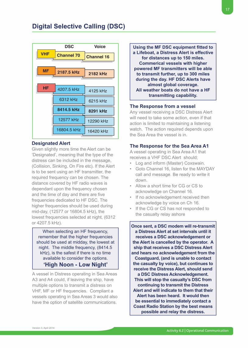
Designated AlertGiven slightly more time the Alert can be ‘Designated’, meaning that the type of the distress can be included in the message, (Collision, Sinking, On Fire etc). If the Alert is to be sent using an HF transmitter, the required frequency can be chosen. The distance covered by HF radio waves is dependant upon the frequency chosen andthetimeofdayandtherearefivefrequencies dedicated to HF DSC. The higher frequencies should be used during mid-day, (12577 or 16804.5 kHz), the lowest frequencies selected at night, (6312 or 4207.5 kHz).
The Response from a vesselAny vessel receiving a DSC Distress Alert will need to take some action, even if that action is limited to maintaining a listening watch. The action required depends upon the Sea Area the vessel is in.
The Response for the Sea Area A1A vessel operating in Sea Area A1 that receives a VHF DSC Alert should;• Log and inform (Master) Coxswain.• Goto Channel 16, listen for the MAYDAY call and message. Be ready to write it down.• Allow a short time for CG or CS to acknowledge on Channel 16.• If no acknowledgement received then acknowledge by voice on Ch 16.• If the CG or CS has not responded to the casualty relay ashore
When selecting an HF frequency,remember that the higher frequencies
should be used at midday, the lowest at night. The middle frequency, (8414.5 kHz), is the safest if there is no time
available to consider the options.‘High Noon - Low Night’
Using the MF DSC equipment fitted to a Lifeboat, a Distress Alert is effective
for distances up to 150 miles. Commerical vessels with higher
powered MF transmitters will be able to transmit further, up to 300 miles during the day. HF DSC Alerts have
almost global coverage.All weather boats do not have a HF
transmitting capability.
Once sent, a DSC modem will re-transmit a Distress Alert at set intervals until it receives a DSC acknowledgement or
the Alert is cancelled by the operator. A ship that receives a DSC Distress Alert
and hears no acknowledgement from the Coastguard, (and is unable to contact
the casualty by voice), but continues to receive the Distress Alert, should send
a DSC Distress Acknowledgement. This will stop the casualty’s DSC from
continuing to transmit the Distress Alert and will indicate to them that their
Alert has been heard. It would then be essential to immediately contact a
Coast Radio Station by the best means possible and relay the distress.
A vessel in Distress operating in Sea Areas A3 and A4 could, if leaving the ship, have multiple options to transmit a distress on VHF, MF or HF frequencies. Compliant a vessels operating in Sea Areas 3 would also have the option of satellite communications.
Activity 6.2 | Operational Communication
18
Version 3, April 2014
Digital Selective Calling (DSC)
The Response for the Sea Area A2A vessel operating in Sea Area A2 that receives a MF DSC Distress alert on 2187.5 kHz should:• Log and inform (Master) Coxswain.• Go To 2182 kHz and listen for the MAYDAY call and message. Be ready to write it down.• Allow a short time for CG or CS to acknowledge.• If no acknowledge is received , acknowledge by voice to the CG or casualty.• If the CG or CS has not responded to the casualty relay ashore
The Response for Sea Areas A3and A4A vessel operating in Sea Area A3 or A4 that receives a DSC Distress alert from a Ship or Mobile Earth Station (M.E.S) on HF frequency 4207.5 KHz - 16804 kHz) should:• Do not acknowledge.• Set watch on the HF/RT frequency associated with the HF DSC frequency.• Write down the distress call and message in the ship’s radio log in case the information needs to be relayed.• Listen for 5 minutes for a Coastguard to Acknowledge.• If no response is heard by either DSC or voice, relay the distress to the shore by any means.
The Response from the ShoreIn the UK, the Coast Station receiving a DSC Distress Alert from Sea Areas A1 and A2, will normally be the Coastguard Maritime Rescue Co-ordination Centre, (MRCC). They will acknowledge the Alert by DSC and attempt to establish voice communications.
In Sea Areas A3 and A4, any coast station aware of a distress will relay the distress to all ships in the area using both radio and satellite communications. By transmitting an ‘area call’ they will alert only those ships in the vicinity of the distress. Ships receiving the Relayed Distress Alert should make immediate contact with the coast station. The co-ordination of assistance for Sea Areas A3 and A4 will normally be controlled by a shore-based Rescue Co-ordination Centre but this might be handed over to a vessel in the immediate area.
If a DSC Distress Alert is sent byaccident, allow the transmission to
finish and stop it repeating. Make an‘All Stations’ Radiotelephone
broadcast cancelling the alert on the appropriate RT frequency, giving both the ship’s identity, (or call sign), and
it’s MMSI number.
Vessels must never acknowledge any distress received, from a ship on HF.
The acknowledgement to an HFDistress Alert or Call must come
from a Coast Station. If noacknowledgement is heard after 5
minutes, then the Distress should be relayed to the nearest Coast Station by the best means possible. If the
distress incident is in your immediate area, respond using VHF.
DO NOT acknowledge by R.T or D.S.C.
19
Activity 6.2 | Operational CommunicationVersion 3, April 2014
DSC Urgency and Safety Alerts
An Urgency or Safety Alert should be sent prior to an R/T call using the appropriate equipment depending on the Sea Area.
By using the various options available within the DSC modem, the transmission can be tailored to alert either ‘All Stations’ or, ‘All Stations’withinaspecifiedgeographicalarea,aspecifiedgrouporfleetofvesselsoronespecificstation,(suchasaCoastguardor Coast Station). Vessels receiving an All Ships DSC Safety Alert should not acknowledge by RT but should maintain a listening watch on the associated RT Calling or Working frequency.
DSC Routine AlertsProvided that the MMSI number of a ship is known then DSC Alerts can be sent from Ship to Ship. This type of Alert will only sound an alarm on the called ship and by reading the Alert message they will be able to identify the caller. By including a proposed Working frequency in the DSC Alert, (and waiting for an acknowledgement accepting this frequency), the subsequent R/T call can then be made directly on a Working frequency.
DSC TestingItisalegalrequirementonGMDSS-fittedvessels that tests should be carried out ontheDSCradioequipmentatspecifiedperiods to ensure that it is fully functional in the event of an emergency. There are two types of test to be performed on MF/HF equipment;
Internal TestsInternal Tests should be performed daily, or in the case of a Lifeboat, each time the boat is used. During an internal test the DSC unit performs a ‘handshake’ with the attached MF/HF radio. That is, it sends a test signal to the MF/HF radio and receives a signal in answer. Provided that these signals are in order the test will be considered satisfactory.
External TestsExternal Tests should be performed weekly and involves sending a Test DSC Alert to an MF equipped Coastguard or Coastal Radio Station. The shore station should then transmit an acknowledgement. Provided this acknowledgement is received satisfactorily, the test will be considered a success.
A DSC Urgency Alert indicates that a very important message concerning
the safety of a ship, aircraft, vehicle, or person is about to follow.
A DSC Safety Alert indicates that a message concerning an important
meteorological or navigational safety warning is about to follow.
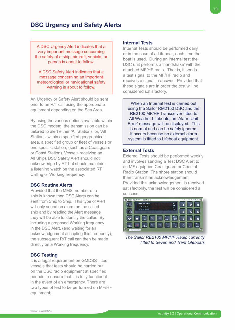
When an Internal test is carried out using the Sailor RM2150 DSC and the RE2100MF/HFTransceiverfittedtoAll Weather Lifeboats, an ‘Alarm Unit
Error’ message will be displayed. This is normal and can be safely ignored, it occurs because no external alarm systemisfittedtoLifeboatequipment.
The Sailor RE2100 MF/HF Radio currently fitted to Seven and Trent Lifeboats
Activity 6.2 | Operational Communication
20
Version 3, April 2014
Emergency Position Indicating Radio Beacons (EPIRBS)
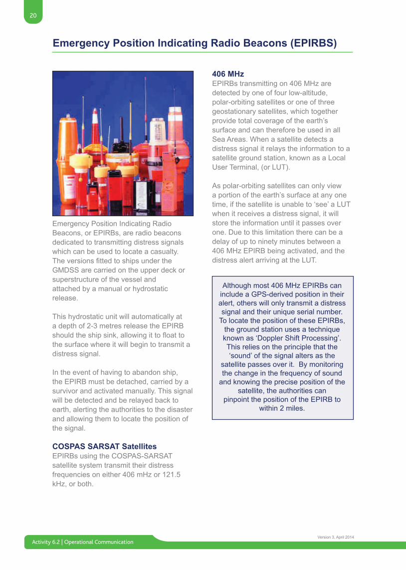
Emergency Position Indicating Radio Beacons, or EPIRBs, are radio beacons dedicated to transmitting distress signals which can be used to locate a casualty. TheversionsfittedtoshipsundertheGMDSS are carried on the upper deck or superstructure of the vessel and attached by a manual or hydrostatic release.
This hydrostatic unit will automatically at a depth of 2-3 metres release the EPIRB shouldtheshipsink,allowingittofloattothe surface where it will begin to transmit a distress signal.
In the event of having to abandon ship, the EPIRB must be detached, carried by a survivor and activated manually. This signal will be detected and be relayed back to earth, alerting the authorities to the disaster and allowing them to locate the position of the signal.
COSPAS SARSAT SatellitesEPIRBs using the COSPAS-SARSAT satellite system transmit their distress frequencies on either 406 mHz or 121.5 kHz, or both.
406 MHzEPIRBs transmitting on 406 MHz are detected by one of four low-altitude, polar-orbiting satellites or one of three geostationary satellites, which together provide total coverage of the earth’s surface and can therefore be used in all Sea Areas. When a satellite detects a distress signal it relays the information to a satellite ground station, known as a Local User Terminal, (or LUT).
As polar-orbiting satellites can only view a portion of the earth’s surface at any one time, if the satellite is unable to ‘see’ a LUT when it receives a distress signal, it will store the information until it passes over one. Due to this limitation there can be a delay of up to ninety minutes between a 406 MHz EPIRB being activated, and the distress alert arriving at the LUT.
Although most 406 MHz EPIRBs can include a GPS-derived position in their alert, others will only transmit a distress signal and their unique serial number.
To locate the position of these EPIRBs, the ground station uses a technique known as ‘Doppler Shift Processing’. This relies on the principle that the ‘sound’ of the signal alters as the
satellite passes over it. By monitoring the change in the frequency of sound
and knowing the precise position of the satellite, the authorities can
pinpoint the position of the EPIRB to within 2 miles.
21
Activity 6.2 | Operational CommunicationVersion 3, April 2014
Emergency Position Indicating Radio Beacons (EPIRBS)
121.5 MHzBecause of the limitations of this system the 121.5MHz portion of the signal is not listened to by the satellite system and is soley used by SAR organisations to directionfind(D/F)thecasualty.
Registering EPIRBsAll 406 MHz EPIRBs will transmit a unique serial number when activated. This serial number should be registered to a particular vessel and the information held on an international database. In the UK the EPIRB database is held by Falmouth MRCC and in ROI its held by COMREG in Dublin. The details held are reproduced on the ship’s radio licence. Should the EPIRB be activated, the serial number can be used to identify the casualty. Consequently an EPIRB should never be loaned to another vessel or sold-on without notifying the authorities. UK registered EPIRBs have a unique serial number. In the ROI however, the serial number is made up of Maritime Identity Digits (MID) 250 and the vessels unique International call sign, for example: 250EI1234.
For obvious reasons, when testing an EPIRB it is imperative that it is de-activated before removal from
its stowage and then re-armed after the test is complete. If an EPIRB is activated accidentally, turn off
immmediately and contact the nearest Coastguard or MRCC.
Testing EPIRBsIt is a legal requirement that all EPIRBs fittedtoGMDSScompulsory-fitvesselsshould be tested once a month. The procedure will vary depending upon the type of EPIRB carried but will generally involve removing any protective cover, cleaning the beacon, operating a built-in self-test, checking the expiry date of the hydrostatic release mechanism and the expiry date of the EPIRB’s batteries.
Activity 6.2 | Operational Communication
22
Version 3, April 2014
Search and Rescue Radar Transponders (SARTS)
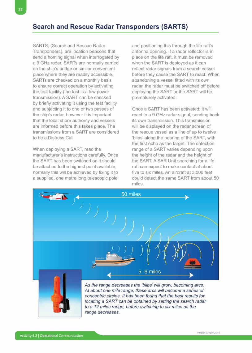
As the range decreases the ‘blips’ will grow, becoming arcs.At about one mile range, these arcs will become a series ofconcentric circles. It has been found that the best results forlocating a SART can be obtained by setting the search radar to a 12 miles range, before switching to six miles as the range decreases.
SARTS, (Search and Rescue Radar Transponders), are location beacons that send a homing signal when interrogated by a 9 GHz radar. SARTs are normally carried on the ship’s bridge or similar convenient place where they are readily accessible. SARTs are checked on a monthly basis to ensure correct operation by activating the test facility (the test is a low power transmission). A SART can be checked bybrieflyactivatingitusingthetestfacilityand subjecting it to one or two passes of the ship’s radar, however it is important that the local shore authority and vessels are informed before this takes place. The transmissions from a SART are considered to be a Distress Call.
When deploying a SART, read the manufacturer’s instructions carefully. Once the SART has been switched on it should be attached to the highest point available, normallythiswillbeachievedbyfixingittoa supplied, one metre long telescopic pole
and positioning this through the life raft’s antennaopening.Ifaradarreflectorisinplace on the life raft, it must be removed when the SART is deployed as it can reflectradarsignalsfromasearchvesselbefore they cause the SART to react. When abandoningavesselfittedwithitsownradar, the radar must be switched off before deploying the SART or the SART will be prematurely activated.
Once a SART has been activated, it will react to a 9 GHz radar signal, sending back its own transmission. This transmission will be displayed on the radar screen of the rescue vessel as a line of up to twelve ‘blips’ along the bearing of the SART, with thefirstechoasthetarget.Thedetectionrange of a SART varies depending upon the height of the radar and the height of the SART. A SAR Unit searching for a life raft can expect to make contact at about fivetosixmiles.Anaircraftat3,000feetcould detect the same SART from about 50 miles.
23
Activity 6.2 | Operational CommunicationVersion 3, April 2014
Search and Rescue Radar Transponders (SARTS)
A second type of SART is available and this is aimed at the AIS system. The Automated IdentificationSystemtransmitsdataonthe VHF channels 87 and 88. The AIS SARTisabletofloatandincorporatesanonboard GPS which will transmit positional data every minute. Only vessels and shore stationsfittedwithanAISreceiverwillbeable to detect the AIS SART.
As well as updatable positional information the AIS SART has a unique MMSI number that starts with 970 followed by 6 numbers making a 9 digit MMSI number (for example; 970991234). The AIS SART will be deployed similar to the radar SART.
An AIS receiver will display a red circle with a cross in it when the SART is activated.
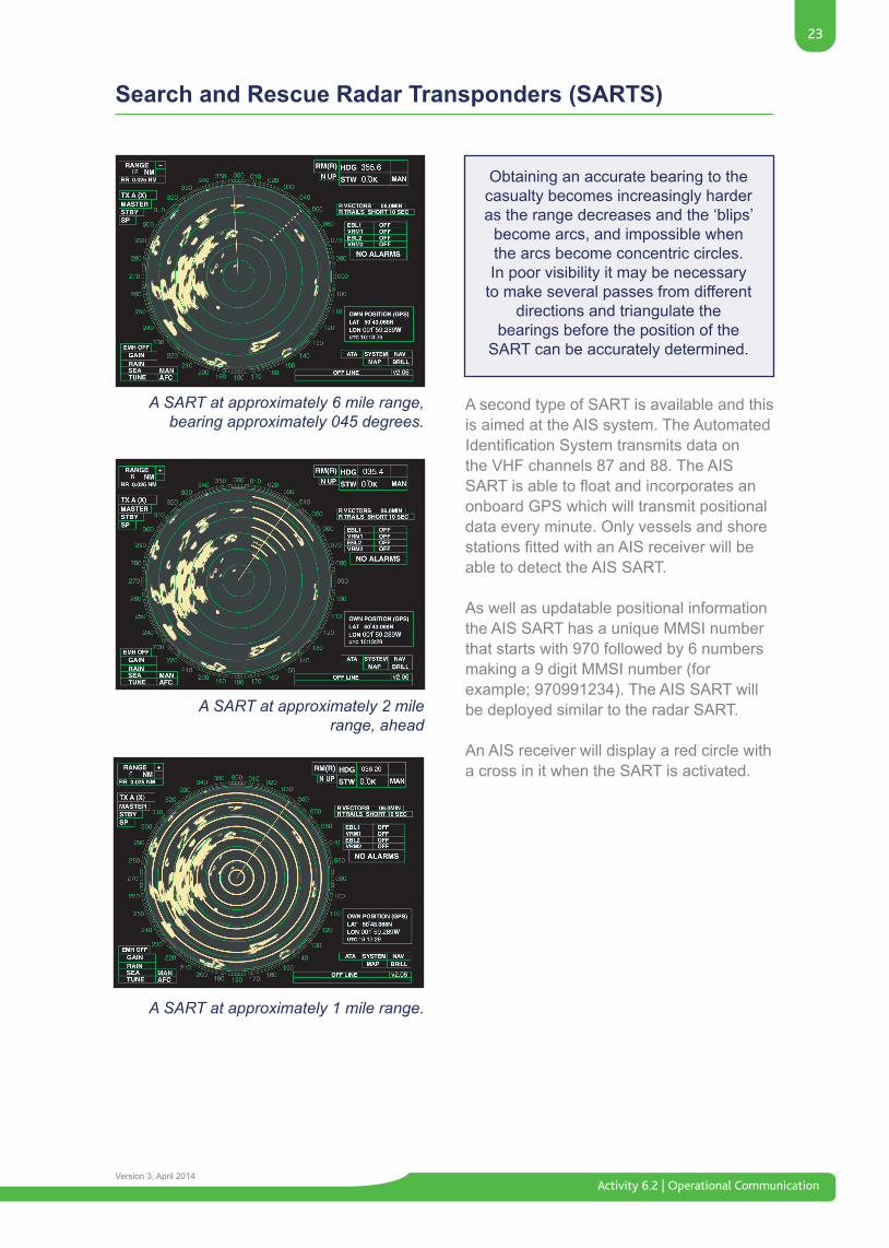
A SART at approximately 6 mile range, bearing approximately 045 degrees.
A SART at approximately 2 milerange, ahead
A SART at approximately 1 mile range.
Obtaining an accurate bearing to the casualty becomes increasingly harder as the range decreases and the ‘blips’
become arcs, and impossible when the arcs become concentric circles. In poor visibility it may be necessary
to make several passes from different directions and triangulate the
bearings before the position of the SART can be accurately determined.
Activity 6.2 | Operational Communication
24
Version 3, April 2014
Maritime Safety Information (NAVTEX)
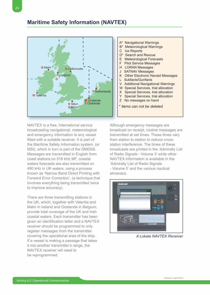
NAVTEX is a free, International service broadcasting navigational, meteorological and emergency information to any vessel fittedwithasuitablereceiver.Itispartofthe Maritime Safety Information system, (or MSI), which in turn is part of the GMDSS. Messages are transmitted in English from coast stations on 518 kHz MF, coastal waters forecasts are also transmitted on 490 kHz in UK waters, using a process known as ‘Narrow Band Direct Printing with Forward Error Correction’, (a technique that involves everything being transmitted twice to improve accuracy).
There are three transmitting stations in the UK, which, together with Valentia and Malin in Ireland and Oostende in Belgium, provide total coverage of the UK and Irish coastal waters. Each transmitter has been givenanidentificationletterandaNAVTEXreceiver should be programmed to only register messages from the transmitter covering the operational area of the ship. If a vessel is making a passage that takes it into another transmitter’s range, the NAVTEX receiver will need tobe reprogrammed.
A* Navigational Warnings B* Meteorological Warnings C Ice Reports D* Search and Rescue E Meteorological Forecasts F Pilot Service Messages H LORAN Messages J SATNAV Messages K Other Electronic Navaid Messages L Subfacts/Gunfacts V Additional Navigational Warnings W Special Services, trial allocation X Special Services, trial allocation Y Special Services, trial allocation Z No messages on hand
* items can not be deleted
Although emergency messages are broadcast on receipt, routine messages are transmitted at set times. These times vary from station to station to reduce cross-station interference. The times of these broadcasts are printed in the ‘Admiralty List of Radio Signals - Volume 3’ while other NAVTEX information is available in the ‘Admiralty List of Radio Signals - Volume 5’ and the various nautical almanacs.
A Lokata NAVTEX Receiver
25
Activity 6.2 | Operational CommunicationVersion 3, April 2014
Antennae / Aerials
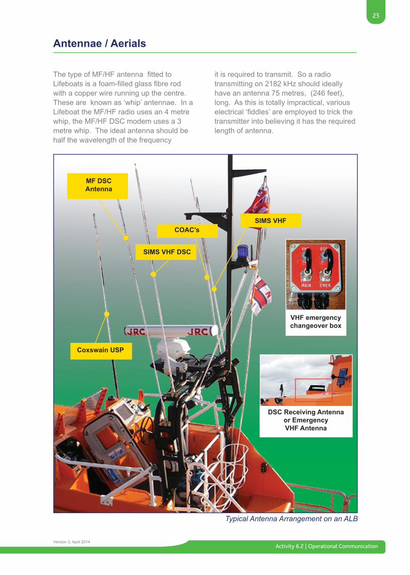
ThetypeofMF/HFantennafittedtoLifeboatsisafoam-filledglassfibrerodwith a copper wire running up the centre. These are known as ‘whip’ antennae. In a Lifeboat the MF/HF radio uses an 4 metre whip, the MF/HF DSC modem uses a 3 metre whip. The ideal antenna should be half the wavelength of the frequency
Typical Antenna Arrangement on an ALB
Coxswain USP
VHF emergencychangeover box
COAC’sSIMS VHF
SIMS VHF DSC
MF DSCAntenna
DSC Receiving Antenna or EmergencyVHF Antenna
it is required to transmit. So a radio transmitting on 2182 kHz should ideally have an antenna 75 metres, (246 feet), long. As this is totally impractical, various electrical‘fiddles’areemployedtotrickthetransmitter into believing it has the required length of antenna.
Activity 6.2 | Operational Communication
26
Version 3, April 2014
Antennae / Aerials
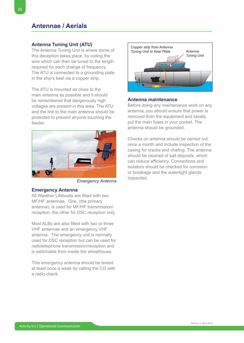
Antenna Tuning Unit (ATU)The Antenna Tuning Unit is where some of this deception takes place, by coiling the wire which can then be tuned to the length required for each change of frequency. The ATU is connected to a grounding plate in the ship’s keel via a copper strip.
The ATU is mounted as close to the main antenna as possible and it should be remembered that dangerously high voltages are present in this area. The ATU and the link to the main antenna should be protected to prevent anyone touching the feeder.
Emergency AntennaAllWeatherLifeboatsarefittedwithtwoMF/HF antennae. One, (the primary antenna), is used for MF/HF transmission/reception, the other for DSC reception only.
MostALBsarealsofittedwithtwoorthreeVHF antennae and an emergency VHF antenna. The emergency unit is normally used for DSC reception but can be used for radiotelephone transmission/reception and is switchable from inside the wheelhouse.
This emergency antenna should be tested at least once a week by calling the CG with a radio check.
Antenna maintenanceBefore doing any maintenance work on any antenna, you should ensure that power is removed from the equipment and ideally put the main fuses in your pocket. The antenna should be grounded.
Checks on antenna should be carried out once a month and include inspection of the casingforcracksandchafing.Theantennashould be cleaned of salt deposits, which canreduceefficiency.Connectionsandisolators should be checked for corrosion or breakage and the watertight glands inspected.
Emergency Antenna
27
Activity 6.2 | Operational CommunicationVersion 3, April 2014
Batteries
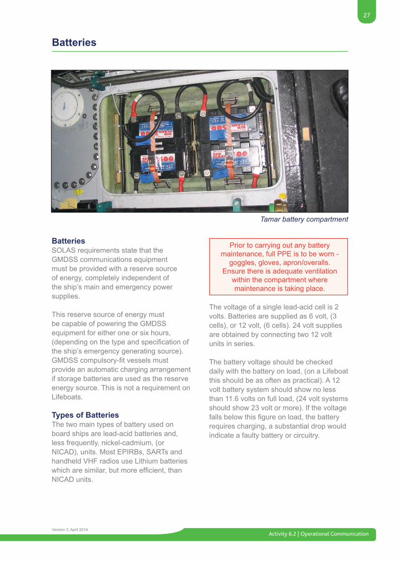
BatteriesSOLAS requirements state that the GMDSS communications equipment must be provided with a reserve source of energy, completely independent of the ship’s main and emergency power supplies.
This reserve source of energy must be capable of powering the GMDSS equipment for either one or six hours, (dependingonthetypeandspecificationofthe ship’s emergency generating source). GMDSScompulsory-fitvesselsmustprovide an automatic charging arrangement if storage batteries are used as the reserve energy source. This is not a requirement on Lifeboats.
Types of BatteriesThe two main types of battery used on board ships are lead-acid batteries and, less frequently, nickel-cadmium, (or NICAD), units. Most EPIRBs, SARTs and handheld VHF radios use Lithium batteries whicharesimilar,butmoreefficient,thanNICAD units.
Tamar battery compartment
The voltage of a single lead-acid cell is 2 volts. Batteries are supplied as 6 volt, (3 cells), or 12 volt, (6 cells). 24 volt supplies are obtained by connecting two 12 volt units in series.
The battery voltage should be checked daily with the battery on load, (on a Lifeboat this should be as often as practical). A 12 volt battery system should show no less than 11.6 volts on full load, (24 volt systems should show 23 volt or more). If the voltage fallsbelowthisfigureonload,thebatteryrequires charging, a substantial drop would indicate a faulty battery or circuitry.
Prior to carrying out any battery maintenance, full PPE is to be worn -
goggles, gloves, apron/overalls.Ensure there is adequate ventilation
within the compartment where maintenance is taking place.
Activity 6.2 | Operational Communication
28
Version 3, April 2014
Batteries
All Weather Lifeboats have a 24 volt DC electrical system, using a two wire insulated return with double pole circuit breaker and switches, in accordance with Lloyds’ requirements. The MF/HF equipment used on an ALB requires 24 volts, while the VHF equipment used on all types of Lifeboats only requires 12 volts.
There are normally two banks of batteries which are charged by two alternators, driven from the main engines. Each alternator can be switched to charge one or both banks of batteries. In addition Severn and Trent Lifeboats have a third, independent battery for the electrical navigationalequipment.MostafloatLifeboats have an auxiliary generator for battery charging when the main engines are not running and all Lifeboats can charge their batteries from an external D.C. supply, usually a battery charger in the boathouse.
The best way of assessing the condition of a lead acid battery is by checking the specificgravity(S.G.)oftheelectrolyte.This should be done after the battery has been topped-up with electrolyte and fully charged. All the cells in a battery should have a similar reading; a variation of more than 0.025 indicates a faulty cell and the battery should be replaced.
The approximate hydrometer readings should be:
Fully Charged 1250 Half Charged 1200 Discharged 1150
Emerging technologies means that leadacidliquidfilledbatteriesarebeingreplacedintheRNLIwithGelfilledones.These new batteries are sealed and have an indicator to indicate state of charge. A green indicator shows that the battery is in a charged state any other colour means it requires charging.
• Keep the battery clean and dry. This will help prevent corrosion of terminals.
• Lightly smear terminal posts, clamps and bus-bars with petroleum jelly, this minimises the risk of corrosion.
• Only use distilled or de-mineralised water when topping-up the electrolyte.
• The level of the electrolyte must always be approx. 1 cm above the plates.
• Don’t leave a battery in a discharged condition.
• Don’t operate a battery for long periods when it is in a low state of charge.
• Don’t leave a fully charged battery for long periods without giving regular ‘top up’ charges.
• Don’t overcharge batteries.
A lead acid battery will producehydrogen gas when being charged.As Hydrogen is highly explosive, a
Lifeboat’s batteries are fully enclosedand vented but care must be taken
during maintenance. ALBs have fans which vent the battery gases and these
should be checked regularly.
When making up electrolyte, always add acid to water, never add water to acid!
29
Activity 6.2 | Operational CommunicationVersion 3, April 2014
Maritime Mobile Service Identity (MMSI) Numbers
AllGMDSS-fittedShipsandCoastStationshaveaunique9-digitidentificationnumber,known as its Maritime Mobile Service Identity number or MMSI number. This can be thought of as it’s ‘telephone’ number.
• UK registered vessels start with the digits 232, 233, 234 or 235 (as in 232000001).
• Irish registered vessels start with the digits 250, (as in 250000001).
• UK Coastguard Stations start with the digits 00232, (as in 002320001).
• Irish Coastguard Stations start with the digits 00250, (as in 002500001).
Groups or Fleets of ships can also have a MMSI to identify them. In the case of UK vessels this will start with 0232 followed by 5 other digits. These are issued by OFCOM, in the ROI COMREG would be the issuing authority.
RNLIDSCfittedSARUnitshavethegroupnumber of 023200002.
The MMSI numbers for ships can be found in the ITU’s ‘List of Ship Stations’ which is updated regularly with supplements. Coast station’s MMSIs also appear in other publications, such as ITU’s ‘List of Coast Stations’ and the ‘Admiralty List of Radio Signals - Volume 1’. To decode an MMSI or Call sign received by DSC or R/T, you would use the ITU’s ‘List of Call signs and Numerical Identities’.
SARaircraftcanalsobeidentifiedbyanMMSI number with 111 followed by the country code and a unique number (for example: 111232123).
AISSARTisidentifiedbythenumber970and 6 digits, for example 970991234.
Activity 6.2 | Operational Communication
30
Version 3, April 2014
Distress
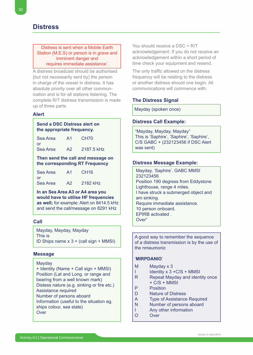
A distress broadcast should be authorised (but not necessarily sent by) the person in charge of the vessel in distress. It has absolute priority over all other commun-ication and is for all stations listening. The complete R/T distress transmission is made up of three parts.
You should receive a DSC + R/T acknowledgement. If you do not receive an acknowledgement within a short period of time check your equipment and resend.
Theonlytrafficallowedonthedistressfrequency will be relating to the distress or another distress should one begin. All communications will commence with:
Send a DSC Distress alert onthe appropriate frequency.
Sea Area A1 CH70orSea Area A2 2187.5 kHz
Then send the call and message onthe corresponding RT Frequency
Sea Area A1 CH16orSea Area A2 2182 kHz
In an Sea Area A3 or A4 area you would have to utilise HF frequencies as well; for example: Alert on 8414.5 kHz and send the call/message on 8291 kHz
Mayday, Mayday, MaydayThis isID Ships name x 3 + (call sign + MMSI)
“Mayday, Mayday, Mayday”This is ‘Saphire’, ‘Saphire’, ‘Saphire’,C/S GABC + (232123456 if DSC Alert was sent)
Mayday (spoken once)
Mayday+ Identity (Name + Call sign + MMSI)Position (Lat and Long. or range and bearing from a well known mark)Distessnature(e.g.sinkingorfireetc.)Assistance requiredNumber of persons aboardInformation (useful to the situation eg. ships colour, sea state)Over
A good way to remember the sequence of a distress transmission is by the use of the nmeumonic
‘MIRPDANIO’M Mayday x 3I Identity x 3 +C/S + MMSIR Repeat Mayday and identity once + C/S + MMSIP PositionD Nature of DistressA Type of Assistance RequiredN Number of persons aboardI Any other informationO Over
Alert
Call
The Distress Signal
Distress Call Example:
Distress Message Example:
Message
Distress is sent when a Mobile EarthStation (M.E.S) or person is in grave and
imminent danger andrequires immediate assistance’.
Mayday, ‘Saphire’. GABC MMSI 232123456Position 190 degress from Eddystone Lighthouse, range 4 miles.I have struck a submerged object and am sinking.Require immediate assistance.10 person onboard.EPIRB activated .Over”
31
Activity 6.2 | Operational CommunicationVersion 3, April 2014
Distress
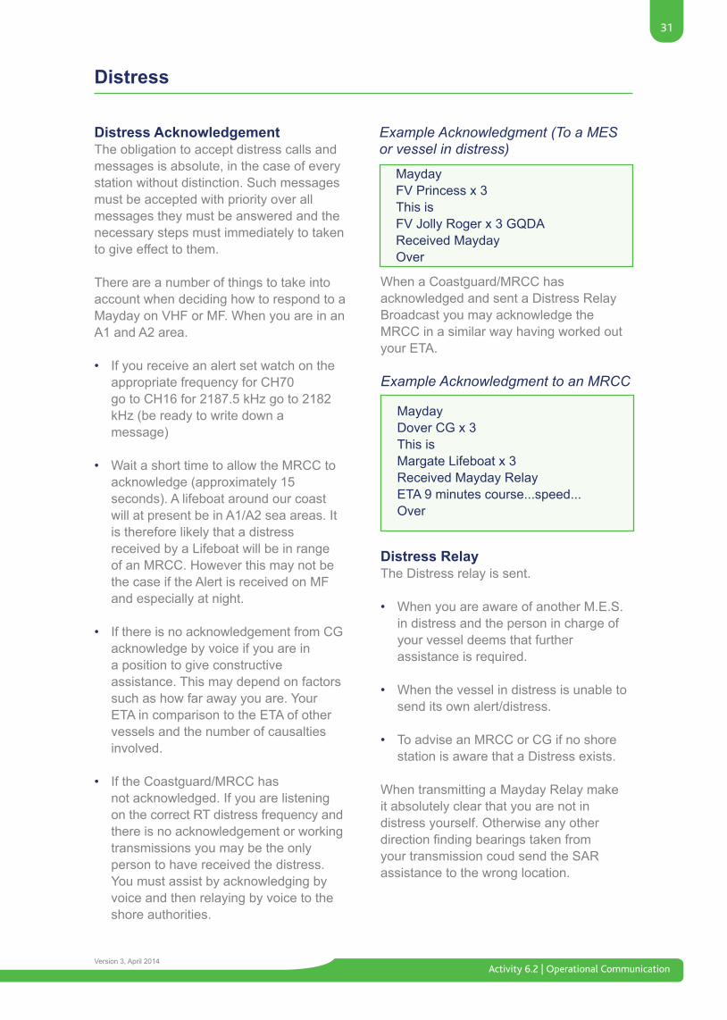
Distress AcknowledgementThe obligation to accept distress calls and messages is absolute, in the case of every station without distinction. Such messages must be accepted with priority over all messages they must be answered and the necessary steps must immediately to taken to give effect to them.
There are a number of things to take into account when deciding how to respond to a Mayday on VHF or MF. When you are in an A1 and A2 area.
• If you receive an alert set watch on the appropriate frequency for CH70 go to CH16 for 2187.5 kHz go to 2182 kHz (be ready to write down a message)
• Wait a short time to allow the MRCC to acknowledge (approximately 15 seconds). A lifeboat around our coast will at present be in A1/A2 sea areas. It is therefore likely that a distress received by a Lifeboat will be in range of an MRCC. However this may not be the case if the Alert is received on MF and especially at night.
• If there is no acknowledgement from CG acknowledge by voice if you are in a position to give constructive assistance. This may depend on factors such as how far away you are. Your ETA in comparison to the ETA of other vessels and the number of causalties involved.
• If the Coastguard/MRCC has not acknowledged. If you are listening on the correct RT distress frequency and there is no acknowledgement or working transmissions you may be the only person to have received the distress. You must assist by acknowledging by voice and then relaying by voice to the shore authorities.
Distress RelayThe Distress relay is sent.
• When you are aware of another M.E.S. in distress and the person in charge of your vessel deems that further assistance is required.
• When the vessel in distress is unable to send its own alert/distress.
• To advise an MRCC or CG if no shore station is aware that a Distress exists.
When transmitting a Mayday Relay make it absolutely clear that you are not in distress yourself. Otherwise any other directionfindingbearingstakenfromyour transmission coud send the SAR assistance to the wrong location.
When a Coastguard/MRCC has acknowledged and sent a Distress Relay Broadcast you may acknowledge the MRCC in a similar way having worked out your ETA.
Example Acknowledgment to an MRCC
MaydayDover CG x 3This isMargate Lifeboat x 3Received Mayday RelayETA 9 minutes course...speed...Over
Example Acknowledgment (To a MES or vessel in distress)
MaydayFV Princess x 3This isFV Jolly Roger x 3 GQDAReceived MaydayOver
Activity 6.2 | Operational Communication
32
Version 3, April 2014
Distress
Alert
Call
Message
Send a DSC Distress Relay Alert on the appropriate frequency.Sea Area A1 CH70 orSea Area A2, 2187.5 kHz Then send the call and message on the corresponding RT frequencySea Area A1 CH16orSea Area A2, 2182.5 kHz
Mayday relay x 3‘All stations’ (or Coastguard name) x 3This isPlymouth Lifeboat x 3
MaydaySaphire GABC MMSI 232123456Position 190 degress from Eddystone Lighthouse range 4 milesStruck a submerged object sinkingRequire immediate assistance10 persons onboardEPIRB activatedOver
A vessel should not acknowledge a Mayday Relay transmitted by a Coastguard unless it is in a position to offer assistance.
Control of communicationsThe control of comunications during a distress lies with either:
• The vessel in distress• The vessel sending a Mayday Relay or• The Coastguard if it has been designed to do so by the vessel in distress. This is the preferred option in coastal waters as the MRCC will have better communication facilities.
Imposing Radio SilenceRadio silence is automatically imposed by the Distress Signal, ‘Mayday’, but should any stations continue to transmit, the station controlling communications will broadcast a message containing the words ‘Seelonce-Mayday’;
For Example
MaydayAll stations x 3This is Lyngby Radio x 3Seelonce MaydayOut
For Example
Mayday all stations x 3This is Falmouth Coastguard x 3Time, one, two three zero‘Saphire’ GABC MMSI 232123456Seelonce FeeneeOut’
Cancelling Radio SilenceWhen the distress is over, the Coastguard will inform everyone that normal radio operations may now take place. To do this they will transmit a similar message to the above, but use the proword, ‘Seelonce Feenee’
33
Activity 6.2 | Operational CommunicationVersion 3, April 2014
Urgency
UrgencyAn urgency call and message indicates that a very important message is to follow concerning the safety of a ship, aircraft, vehicle or person.
An urgency message is the second most important in order of priority calls and messages, below distress and must be authorised (but not necessarily sent) by the person in charge of the vessel.
Alert
Call
Message
Send a DSC Urgency Alert on the appropriate frequency.
Sea Area A1 CH70 orSea Area A2, 2187.5 kHz
Then send the call and message on the corresponding RT frequency
Sea Area A1 CH16orSea Area A2, 2182 kHz
PAN PAN, PAN PAN, PAN PANAll stations’ (or Coastguard name) x 3This isSaphire x 3 GABC 232123456
340 Degress 6 miles from Lundy islandLost propeller drifting south at two knotsRequire a tow urgentlyOver.
The Urgency Signal is PAN PANUrgency Alerts and Calls requesting medical advise are usually addressed to Coastguard or Coast Stations. After your initial broadcast on the CH16 or 2182 kHz you will normally be moved to a working channel were you will be connected by landline to a doctor.
Once you have been moved to a working frequency you will be asked for the ship’s position and nearest or next port with an ETA. The patient’s symptoms and advice required. The type of medication carried onboard or available.
Activity 6.2 | Operational Communication
34
Version 3, April 2014
Safety
Alert
Call
Send a DSC Safety Alert on Channel CH70 go to CH16
Securite, Securite, SecuriteAll Stations, All Stations, All StationsThis isTroon Lifeboat, Troon Lifeboat, Troon Lifeboat MMSI 235010881
SafetyA safety transmission indcates that an important meteorological or navigational message is to follow. The safety transmission is the third most important in the priority order after Distress and Urgency.
As always, if you have a DSC, the correct alertshouldbesentfirst.Navigationwarnings from ships are usually sent on VHF as navigational information is usually only of interest to shipping within the vicinity of the navigation danger.
The Coast Station normally broadcasts safety messages to ‘All Stations’ on receipt. Thesearethenrepeatedatspecifictimesthroughout the day. The Coast Station will not normally use the DSC and will send his meteorological and navigational warnings on a working frequency after an announcement on CH16. They may also make the call on 2182 kHz and give an MF working frequency for the warnings.
Message
Navigational warning Position 55 Deg 20 min North 005 degress 10 min WestTowingpartsubmergedfishingvesselBound TroonWide berth requestedtime 1300 UTC Out
35
Activity 6.2 | Operational CommunicationVersion 3, April 2014
Regulations
Radio LicensesThere are three different licences required before any radio transmitter can be used aboard a ship.
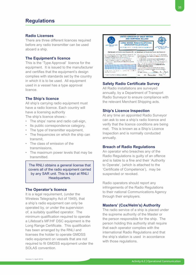
The Equipment’s licenceThis is the ‘Type Approval’ licence for the equipment. It is issued to the manufacturer andcertifiesthattheequipment’sdesigncomplies with standards set by the country in which it is to be used. All equipment used in a vessel has a type approval licence.
The Ship’s licenceAll ship’s carrying radio equipment must have a radio licence. Each country will have a licensing authorityThe ship’s licence shows:-• The ships’ name and radio call-sign,• Its public correspondence category,• The type of transmitter equipment,• The frequencies on which the ship can transmit,• The class of emission of the transmissions,• The maximum power levels that may be transmitted.
The Operator’s licenceIt is a legal requirement, (under the Wireless Telegraphy Act of 1949), that a ship’s radio equipment can only be operated by, or under the supervision of,asuitablyqualifiedoperator.Theminimumqualificationrequiredtooperatea Lifeboat’s MF/HF DSC equipment is the LongRangeCertificate.Thisqualificationhas been arranged by the RNLI and licenses the holder to operate GMDSS radio equipment on vessels that are not requiredtofitGMDSSequipmentundertheSOLAS convention.
The RNLI obtains a general license that covers all of the radio equipment carried
by any SAR unit. This is kept at RNLI Headquarters.
Safety Radio Certificate SurveyAll Radio installations are surveyed annually, by a Department of Transport Radio Surveyor to ensure compliance with the relevant Merchant Shipping acts.
Ship’s Licence Inspection At any time an appointed Radio Surveyor can ask to see a ship’s radio licence and verify that the licence conditions are being met. This is known as a Ship’s Licence Inspection and is normally conducted annually.
Breach of Radio RegulationsAn operator who breaches any of the Radio Regulations is guilty of an offence andisliabletoafineandtheir‘Authorityto Operate’, (which is attached to the ‘CertificateofCompetence’),maybesuspended or revoked.
Radio operators should report any infringements of the Radio Regulations to their national Communications Agency through their employers.
Masters’ (Cox/Helm’s) AuthorityThe radio service of a ship is placed under the supreme authority of the Master or the person responsible for the ship. The person holding this authority shall require that each operator complies with the international Radio Regulations and that the ship’s station is used in accordance with those regulations.
Activity 6.2 | Operational Communication
36
Version 3, April 2014
Regulations
Secrecy of CorrespondenceAll radio operators are required to know the legislation regarding the secrecy of correspondence. Radio personnel and all persons who become acquainted with the contents of radio-telegrams, radiotelephone calls, or radio-telex calls are bound to preserve the secrecy of correspondence. No person shall divulge the contents or even the existence of correspondence transmitted, received, or intercepted by a radio station.
‘The interception of radio-communication correspondence, other than that which the station is authorised to receive, is forbidden and in the case where such correspondence is involuntarily received, it shall not be reproduced, nor communicated to third parties, nor used for any purpose, and even its existence shall not be disclosed’. A copy of the relevant legislation should be exhibited in every Boathouse.
Test TransmissionsAll tests of radio transmitters must last no longer than 10 seconds and must include the name or call sign of the station making the test.
Whenever practicable, tests should be carriedoutonanartificialantennaeorwith reduced power. Permission must be sought from other stations if any tests or adjustments are necessary and are liable to cause interference.
Radio Equipment TestsDaily testsa) Internal test of DSC equipment, (without transmitting).b) Batteries, test and charge as required.c) Printer(s),(wherefitted).Weeklya) External test of DSC equipment by means of a live test call to a coast station.b) Test of Reserve Source of Energy (when not a battery) e.g. generator set.
c) Survival craft VHF radio’s on a working channel (not on Channel 16).Monthlya) All EPIRBs using built in test facilities.b) Check each SART for security and signs of damage and test as directed by the manufacturer. c) Check all batteries providing energy for any part of the radio installation. Check the security and condition of the batteries, connections and compartment.d)Electrolytelevelandspecificgravityof each cell
Transmission Rules (Avoidance of Interference)All stations are forbidden to carry out:• Transmissionswithoutidentificationor falseidentification.• Closingdownbeforefinishingall operations with other users, (Lifeboats must inform the Coastguard before closing down when returning to the boathouse after an exercise or service).• Transmissions containing foul or obscene language.• Transmissions using frequencies/ channels not covered by the operator’s licence.• Transmissions intended for shore reception, other than to Coastguard/ Coast Radio Stations and Private Channels.• Transmission of false or deceptive Distress, Urgency or Safety messages.• The broadcasting of music or entertainment.• Unnecessary signalling (excessive calling etc).• Unauthorised use of radio equipment for the transmission or reception of private correspondence.• Any emission capable of causing interference on frequencies allocated to Distress, Urgency or Safety communications.
37
Activity 6.2 | Operational CommunicationVersion 3, April 2014
Regulations
Time KeepingUniversal Time Coordinated (U.T.C.) should be used for all radio communicationslog-keeping and message-timing purposes, (used to be known as GMT or Zulu time). Time signals are broadcast from certain stations, details of which can be found in the ITU List of Radio determination and Special Service Stations.
Identification of StationsAll stations must identify themselves when making a transmission.
Coast StationsCoast Stations normally identify themselves using their geographical location, followed by the word ‘radio’ e.g. ‘Valentia Radio’, ‘Sydney Radio’, ‘Singapore Radio’, etc. Coast Stations are also allocated an international radio callsign. For example ‘EJK’ is allocated to Valentia.
Inaddition,CoastStationsfittedwithDSCwill also have a 9 digit MMSI number. For example ‘Valentia Radio’ has the call sign ‘EJK’ and a MMSI number of 002500200.
Ships StationShips should identify themselves by the use of the ship’s name and/or the International radio Call Sign assigned to the ship.
Ships using D.S.C must use the ship’s 9 digit M.M.S.I. number.
Ship Earth (Satellite) Stations must use the 9 digit (Standard C) INMARSAT identity number.
Radio WatchAllshipsthatarerequiredtofitGMDSSequipment are also legally obliged to maintain a radio watch on certain frequencies. These frequencies vary according to their area of operation, as follows;
Area A1 - VHF Channel 70, Channel 16 and Channel 13
Area A2 - Channel 16, Channel 13, Channel 70, 2182 kHz and 2187.5 kHz
Area A3/A4- Channel 16, Channel 13, Channel 70, 2182 kHz, 2187.5 kHz, 8414.5 kHz plus one other HF frequency, (4207.5 kHz, 6312 kHz, 12577 kHz, 16804.5 kHz) as appropriate to the time of day. This may be done by the use of a scanning receiver.
GMDSS Radio LogbookAllGMDSScompulsory-fittedvesselsmustkeep a radio logbook on the navigating bridge convenient to the radio installation. This Radio Logbook has three sections;
Section A:- Particulars of the ship.Ship’s name.Call sign.Port of registry.Gross tonnage.IMO number.Sea areas in which ship is authorised to operate.Method used to ensure availability of equipment.Duplication of equipment, (DOE).Shore based maintenance, (SBM).At sea maintenance, (ASM).Name and address of owner/managing owner or agent.
Activity 6.2 | Operational Communication
38
Version 3, April 2014
Section B:- Name(s), of radio personnel. Dates onboard.Certificatenumber(s).Classofcertificate(s).Name of person designated for radio-communications during emergencies.Name of person nominated to carry out appropriate tests andchecks and log entries.
Section C:- Record of all communications
This radio logbook should contain a record of the following, together with the time the incidents took place;
• A summary of all communications relating to Distress, Urgency and Safety traffic.• A record of any important incidents connected with the radio service.• Where appropriate, the position of the ship at least once a day.
The master should inspect and sign each day’s entry in the GMDSS radio logbook including details of the daily, weekly and monthly checks and tests.
Documents to be carriedUnitedKingdomregisteredGMDSSfittedships must carry:-• Ships licence.• Certificate(s)oftheradiooperators.• The GMDSS radio logbook.• ITU list of Callsigns and numerical Identities.• Manual for use of; Maritime Mobile Service Maritime Mobile Satellite Service• ITU List of Ship Stations.• ITU list of Call Signs and Numerical • Identities.• Admiralty List of Radio Signals.• Wireless telegraphy Act 1949
Order of Priority of Communications1. Distress2. Urgency3. Safety4. All other communications realating to directionfinding(DF).
Allowable tranmissions in UK Harbours and Inland WaterwaysExchange of communications through coast stations;
• Reception of broadcast messages.• Exchange of communications in a port operations service.• Onboard communications using VHF Channel 15 or 17. • Intership communication between ships is permitted on inland waterways provided both ships are underway.
Different Types of StationsThe GMDSS does not just apply to Ship’s stations, there are several other radio stations involved.
• Coast Stations; land-based radio stations based on the coast providing ship to shore radio communications.• Pilot stations; radio stations used exclusively by ship’s pilots who provide guidance for ships manouvering in areas where local knowledge is essential.• Aircraft Stations; radio stations in aircraft. • Maritime Rescue Co-ordination Centres; coastguard stations that co-ordinate search and rescue operations.
Regulations
39
Activity 6.2 | Operational CommunicationVersion 3, April 2014
Appendix 1 - Glossary
AGC Automatic Gain Control.ALRS Admiralty List of Radio Signals.AOR E Atlantic Ocean Region (East), coverage area of INMARSAT satellite.AOR W Atlantic Ocean Region (West), coverage area of INMARSAT satellite.
The other two inmarset satellites are IOR and POR (IndianandPacific)
Associated Rescue Co-ordination Centre (ARCC) A centre nominated by the national SAR agency to which an INMARSAT Coast Earth Station (CES) normally routes distress calls.
Bridge to Bridge Communications. These are inter-ship VHF radiotelephone communications for the purpose of assisting the safe movement of ships.
CG Coastguard.COACS Call out and Communications System
Co-ordinator Surface Search A vessel, other than a rescue unit, designated to co-ordinate surface search and rescue operationswithinaspecifiedsearcharea.
Land Earth Station (LES) An earth station inthefixedsatelliteservice.
Coast Radio Station A land station in the maritime mobile service.
Continuous Watch Means that the radio watch concerned shall not be interrupted other than for brief intervals when the ship’s receiving capability is impaired or blocked by its own communications or when the facilities are under periodic maintenance or checks.
COSPAS-SARSAT system A satellite-aided search and rescue system based on low-altitude near-polar-orbiting satellites and designed to locate distress beacons transmitting on the frequencies 121.5 MHz and 406 MHz.
CRS Coast Radio Station.CW Continuous Wave (Morse Code).DF Direction Finding.
DGPS Differential Global Positioning System.
Digital Selective Calling (DSC) A technique using digital codes which enables a radio station to establish contact with, and transfer information to another station or group of stations.
Direct-printing Telegraphy Automated telegraphy techniques which comply with the relevant recommendations of the International Consultative Committee (CCIR).
Distress Alerting Rapid and successful reporting of a distress incident to a unit which can provide or co-ordinate assistance.
Distress Call A part of the distress communication procedure, which includes a transmission of the distress-priority request message followed by the station’s identity.
FM Frequency Modulation.Fx Frequency.
General Communications Those communications between ship stations and shore based stations, which concern the management and operation of the ship, normally taken to mean public correspondence to the exclusion of safety, distress and urgency messages. These communications may be conducted on the appropriate frequencies.
Geostationary-Satellite Orbit The orbit of a geo-synchronous satellite whose circular and direct orbit lies in the plane of the Earth’s equator.
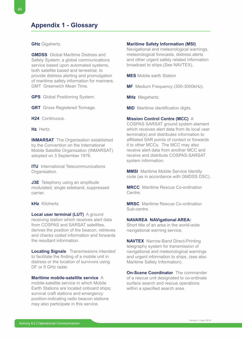
Activity 6.2 | Operational Communication
40
Version 3, April 2014
GHz Gigahertz.
GMDSS Global Maritime Distress and Safety System; a global communications service based upon automated systems, both satellite based and terrestrial, to provide distress alerting and promulgation of maritime safety information for mariners.GMT Greenwich Mean Time.
GPS Global Positioning System.
GRT Gross Registered Tonnage.
H24 Continuous.
Hz Hertz.
INMARSAT The Organisation established by the Convention on the International Mobile Satellite Organisation (INMARSAT) adopted on 3 September 1976.
ITU International Telecommunications Organisation.
J3E Telephony using an amplitude modulated, single sideband, suppressed carrier.
kHz Kilohertz.
Local user terminal (LUT) A ground receiving station which receives alert data from COSPAS and SARSAT satellites, derives the position of the beacon, retrieves and checks coded information and forwards the resultant information.
Locating Signals Transmissions intended tofacilitatethefindingofamobileunitindistress or the location of survivors using DF or 9 GHz radar.
Maritime mobile-satellite service A mobile-satellite service in which Mobile Earth Stations are located onboard ships; survival craft stations and emergency position-indicating radio beacon stations may also participate in this service.
Maritime Safety Information (MSI) Navigational and meteorological warnings, meteorological forecasts, distress alerts and other urgent safety related information broadcast to ships.(See NAVTEX).
MES Mobile earth Station
MF Medium Frequency (300-3000kHz).
MHz Megahertz.
MIDMaritimeidentificationdigits.
Mission Control Centre (MCC) A COSPAS SARSAT ground system element which receives alert data from its local user terminal(s) and distributes information to affiliatedSARpointsofcontactorforwardsit to other MCCs. The MCC may also receive alert data from another MCC and receive and distribute COSPAS-SARSAT system information.
MMSI Maritime Mobile Service Identity code (as in accordance with GMDSS DSC).
MRCC Maritime Rescue Co-ordination Centre.
MRSC Maritime Rescue Co-ordination Sub-centre.
NAVAREA NAVigational AREA: Short title of an area in the world-wide navigational warning service.
NAVTEX Narrow-Band Direct-Printing telegraphy system for transmission of navigational and meteorological warnings and urgent information to ships, (see also Maritime Safety Information).
On-Scene Coordinator The commander of a rescue unit designated to co-ordinate surface search and rescue operations withinaspecifiedsearcharea.
Appendix 1 - Glossary
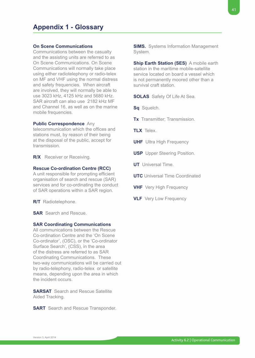
41
Activity 6.2 | Operational CommunicationVersion 3, April 2014
Appendix 1 - Glossary
On Scene Communications Communications between the casualty and the assisting units are referred to as On Scene Communications. On Scene Communications will normally take place using either radiotelephony or radio-telex on MF and VHF using the normal distress and safety frequencies. When aircraft are involved, they will normally be able to use 3023 kHz, 4125 kHz and 5680 kHz. SAR aircraft can also use 2182 kHz MF and Channel 16, as well as on the marine mobile frequencies.
Public Correspondence Any telecommunicationwhichtheofficesandstations must, by reason of their being at the disposal of the public, accept for transmission.
R/X Receiver or Receiving.
Rescue Co-ordination Centre (RCC) Aunitresponsibleforpromptingefficientorganisation of search and rescue (SAR) services and for co-ordinating the conduct of SAR operations within a SAR region.
R/T Radiotelephone.
SAR Search and Rescue.
SAR Coordinating Communications All communications between the Rescue Co-ordination Centre and the ‘On Scene Co-ordinator’, (OSC), or the ‘Co-ordinator Surface Search’, (CSS), in the area of the distress are referred to as SAR Coordinating Communications. These two-way communications will be carried out by radio-telephony, radio-telex or satellite means, depending upon the area in which the incident occurs.
SARSAT Search and Rescue Satellite Aided Tracking.
SART Search and Rescue Transponder.
SIMS. Systems Information Management System.
Ship Earth Station (SES) A mobile earth station in the maritime mobile-satellite service located on board a vessel which is not permanently moored other than a survival craft station.
SOLAS Safety Of Life At Sea.
Sq Squelch.
Tx Transmitter; Transmission.
TLX Telex.
UHF Ultra High Frequency
USP Upper Steering Position.
UT Universal Time.
UTC Universal Time Coordinated
VHF Very High Frequency
VLF Very Low Frequency
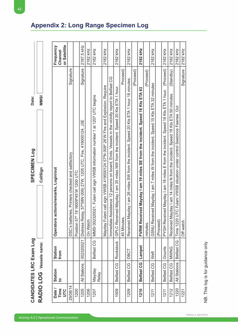
Activity 6.2 | Operational Communication
42
Version 3, April 2014
Appendix 2: Long Range Specimen Log
NB
. Thi
s lo
g is
for g
uida
nce
only
CA
ND
IDAT
ES L
RC
Exa
m L
ogR
AD
IO L
OG
Vess
els
nam
e:C
allS
ign
MM
SI
Dat
e:SP
ECIM
EN L
og
Dat
e /
Tim
eU
TC
Stat
ion
toSt
atio
n fr
omO
pera
tors
act
ions
/rem
arks
, Log
in/o
utFr
eque
ncy
Cha
nnel
or S
atel
itte
29/0
8/14
DS
C’s
bat
terie
s, P
rinte
rs c
heck
ed a
nd s
atifa
ctor
y
S
igna
ture
1200
Pos
ition
57º
19’
N00
9º45
’W 1
200
UTC
1205
All S
tatio
ns00
2320
021
Dis
tress
Rel
ay, 5
7º58
N 0
09) 2
7W, 1
205
UTC
, Fire
, 419
0001
24, J
3E
S
igna
ture
2187
.5 k
Hz
1206
On
Wat
ch21
82 k
Hz
1207
May
day
Rel
ayB
elfa
st C
GM
MSI
002
3200
21. F
ulan
i cal
l sig
n VW
SB in
form
atio
n nu
mbe
r 1 a
t 120
7 U
TC b
egin
s21
82 k
Hz
May
day
Fula
ni c
all s
ign
VW
SB
419
0001
24 5
7ºN
009
º 26’
W F
Ire a
nd E
xplo
sion
, Req
uire
2182
kH
zIm
med
iate
Ass
ista
nce
12 p
erso
ns o
n bo
ard,
End
s. V
esse
ls in
the
vici
nity
repo
rt to
Bel
fast
CG
1009
Bel
fast
CG
Roc
ksto
ckG
PLC
Rec
eive
d M
ayda
y I a
m 3
5 m
iles
NW
from
the
inci
dent
. Spe
ed 2
0 K
ts E
TA 1
hou
r. 21
82 k
Hz
45 M
inut
es.
Pro
ceed
)12
09B
elfa
st C
GD
BC
TR
ecei
ved
May
day
I am
26
mile
s S
W fr
om th
e in
cide
nt. S
peed
20
Kts
ETA
1 h
our 1
8 m
inut
es.
2182
kH
z
(P
roce
ed)
1210
Bel
fast
CG
Lam
pet
FVR
W R
ecei
ved
May
day
I am
19
mile
s SE
from
the
inci
dent
. Spe
ed 1
8 K
ts E
TA 6
3 21
82 k
Hz
min
utes
.
(Pro
ceed
)12
11B
elfa
st C
GW
eft
GS
NU
Rec
eive
d M
ayda
y I a
m 7
mile
s W
from
the
inci
dent
. Spe
ed 1
5 K
ts E
TA 3
2 m
inut
es
2182
kH
z(P
roce
ed)
1211
Bel
fast
CG
Gou
rds
PY
GH
Rec
eive
d M
ayda
y I a
m 1
8 m
iles
E fr
om th
e in
cide
nt. S
peed
18
Kts
ETA
1 h
our.
(P
roce
ed)
2182
kH
z
1212
Bel
fast
CG
MW
NG
Rec
eive
d M
ayda
y I a
m 1
4 m
iles
N fr
om th
e in
cide
nt. S
peed
18
Kts
ETA
50
min
utes
.
(Sta
ndby
)21
82 k
Hz
122
0A
ll S
tatio
nsB
elfa
st C
GTi
me
1220
UTC
Ful
ani V
WS
B s
ituat
ion
unde
r con
trol S
eelo
nce
Feen
ee. O
ut21
82 k
Hz
1221
Off
wat
ch.
Sig
natu
re21
82 k
Hz
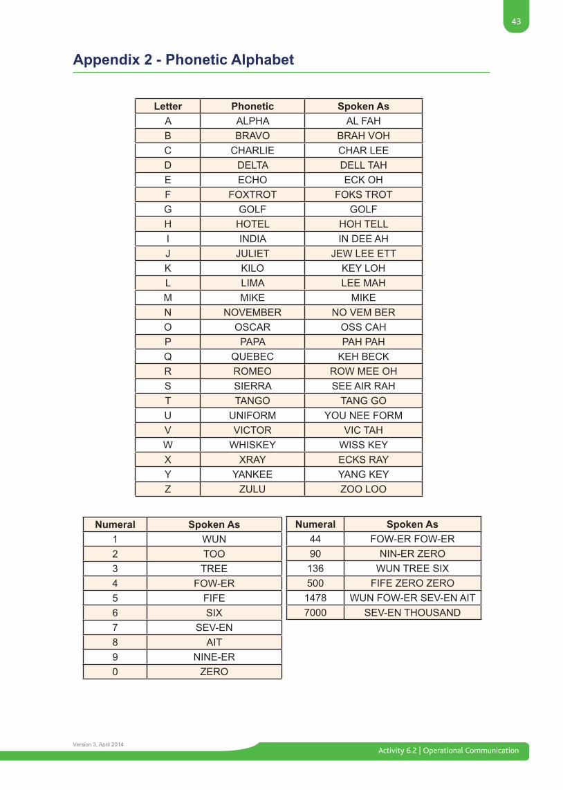
43
Activity 6.2 | Operational CommunicationVersion 3, April 2014
Appendix 2 - Phonetic Alphabet
Letter Phonetic Spoken AsA ALPHA AL FAHB BRAVO BRAH VOHC CHARLIE CHAR LEED DELTA DELL TAHE ECHO ECK OHF FOXTROT FOKS TROTG GOLF GOLFH HOTEL HOH TELLI INDIA IN DEE AHJ JULIET JEW LEE ETTK KILO KEY LOHL LIMA LEE MAHM MIKE MIKEN NOVEMBER NO VEM BERO OSCAR OSS CAHP PAPA PAH PAHQ QUEBEC KEH BECKR ROMEO ROW MEE OHS SIERRA SEE AIR RAHT TANGO TANG GOU UNIFORM YOU NEE FORMV VICTOR VIC TAHW WHISKEY WISS KEYX XRAY ECKS RAYY YANKEE YANG KEYZ ZULU ZOO LOO
Numeral Spoken As1 WUN2 TOO3 TREE4 FOW-ER5 FIFE6 SIX7 SEV-EN8 AIT9 NINE-ER0 ZERO
Numeral Spoken As44 FOW-ER FOW-ER90 NIN-ER ZERO136 WUN TREE SIX500 FIFE ZERO ZERO
1478 WUN FOW-ER SEV-EN AIT7000 SEV-EN THOUSAND
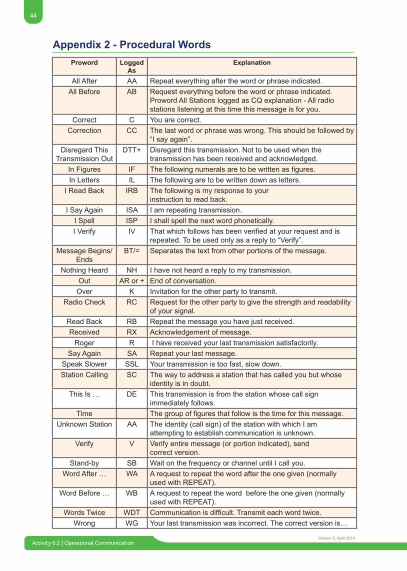
Activity 6.2 | Operational Communication
44
Version 3, April 2014
Proword Logged As
Explanation
All After AA Repeat everything after the word or phrase indicated. All Before AB Request everything before the word or phrase indicated.
Proword All Stations logged as CQ explanation - All radiostations listening at this time this message is for you.
Correct C You are correct.Correction CC The last word or phrase was wrong. This should be followed by
“I say again”.Disregard This
Transmission Out DTT+ Disregard this transmission. Not to be used when the
transmission has been received and acknowledged.In Figures IF Thefollowingnumeralsaretobewrittenasfigures.In Letters IL The following are to be written down as letters.
I Read Back IRB The following is my response to yourinstruction to read back.
I Say Again ISA I am repeating transmission.I Spell ISP I shall spell the next word phonetically.I Verify IV Thatwhichfollowshasbeenverifiedatyourrequestandis
repeated. To be used only as a reply to “Verify”.Message Begins/
EndsBT/= Separates the text from other portions of the message.
Nothing Heard NH I have not heard a reply to my transmission. Out AR or + End of conversation.Over K Invitation for the other party to transmit.
Radio Check RC Request for the other party to give the strength and readability of your signal.
Read Back RB Repeat the message you have just received.Received RX Acknowledgement of message.
Roger R I have received your last transmission satisfactorily.Say Again SA Repeat your last message.
Speak Slower SSL Your transmission is too fast, slow down.Station Calling SC The way to address a station that has called you but whose
identity is in doubt.This Is … DE This transmission is from the station whose call sign
immediately follows.Time Thegroupoffiguresthatfollowisthetimeforthismessage.
Unknown Station AA The identity (call sign) of the station with which I amattempting to establish communication is unknown.
Verify V Verify entire message (or portion indicated), sendcorrect version.
Stand-by SB Wait on the frequency or channel until I call you.Word After … WA A request to repeat the word after the one given (normally
used with REPEAT).Word Before … WB A request to repeat the word before the one given (normally
used with REPEAT). Words Twice WDT Communicationisdifficult.Transmiteachwordtwice.
Wrong WG Your last transmission was incorrect. The correct version is…
Appendix 2 - Procedural Words
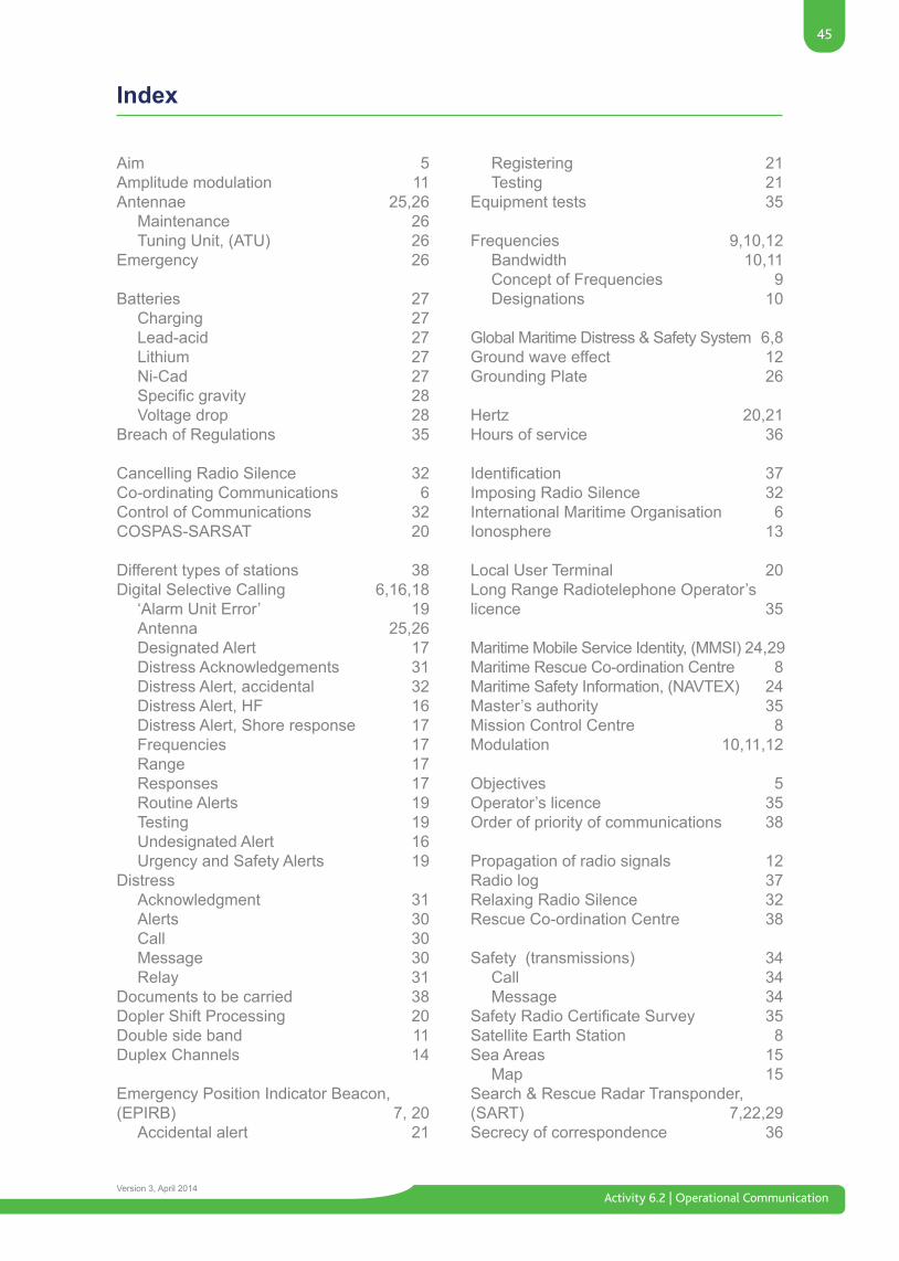
45
Activity 6.2 | Operational CommunicationVersion 3, April 2014
Index
Aim 5Amplitude modulation 11Antennae 25,26 Maintenance 26 Tuning Unit, (ATU) 26 Emergency 26
Batteries 27 Charging 27 Lead-acid 27 Lithium 27 Ni-Cad 27 Specificgravity 28 Voltage drop 28Breach of Regulations 35
Cancelling Radio Silence 32Co-ordinating Communications 6Control of Communications 32COSPAS-SARSAT 20
Different types of stations 38Digital Selective Calling 6,16,18 ‘Alarm Unit Error’ 19 Antenna 25,26 Designated Alert 17 Distress Acknowledgements 31 Distress Alert, accidental 32 Distress Alert, HF 16 Distress Alert, Shore response 17 Frequencies 17 Range 17 Responses 17 Routine Alerts 19 Testing 19 Undesignated Alert 16 Urgency and Safety Alerts 19Distress Acknowledgment 31 Alerts 30 Call 30 Message 30 Relay 31Documents to be carried 38Dopler Shift Processing 20Double side band 11Duplex Channels 14
Emergency Position Indicator Beacon,(EPIRB) 7, 20 Accidental alert 21
Registering 21 Testing 21Equipment tests 35
Frequencies 9,10,12 Bandwidth 10,11 Concept of Frequencies 9 Designations 10
Global Maritime Distress & Safety System 6,8Ground wave effect 12Grounding Plate 26
Hertz 20,21Hours of service 36
Identification 37Imposing Radio Silence 32International Maritime Organisation 6Ionosphere 13
Local User Terminal 20Long Range Radiotelephone Operator’s licence 35
Maritime Mobile Service Identity, (MMSI) 24,29Maritime Rescue Co-ordination Centre 8Maritime Safety Information, (NAVTEX) 24Master’s authority 35Mission Control Centre 8 Modulation 10,11,12
Objectives 5Operator’s licence 35Order of priority of communications 38
Propagation of radio signals 12Radio log 37Relaxing Radio Silence 32Rescue Co-ordination Centre 38
Safety (transmissions) 34 Call 34 Message 34SafetyRadioCertificateSurvey 35Satellite Earth Station 8Sea Areas 15 Map 15Search & Rescue Radar Transponder,(SART) 7,22,29Secrecy of correspondence 36
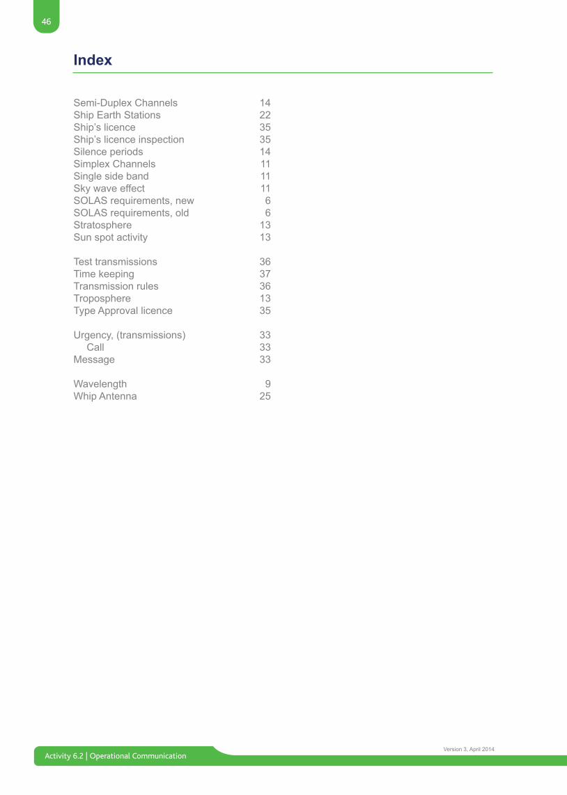
Activity 6.2 | Operational Communication
46
Version 3, April 2014
Index
Semi-Duplex Channels 14Ship Earth Stations 22Ship’s licence 35Ship’s licence inspection 35Silence periods 14Simplex Channels 11Single side band 11Sky wave effect 11 SOLAS requirements, new 6SOLAS requirements, old 6Stratosphere 13Sun spot activity 13
Test transmissions 36Time keeping 37Transmission rules 36Troposphere 13Type Approval licence 35
Urgency, (transmissions) 33 Call 33 Message 33
Wavelength 9Whip Antenna 25

This page has been left intentionally blank
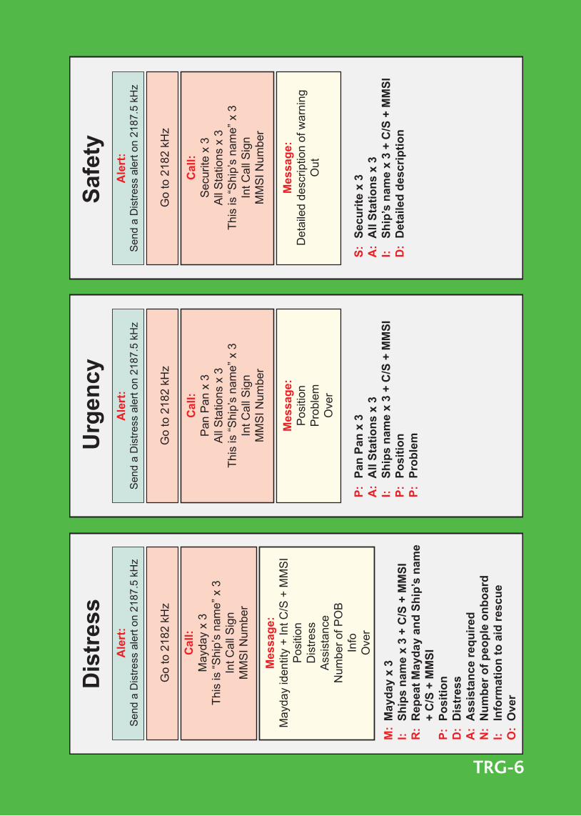
Dis
tress
Urg
en
cy
Safe
tyA
lert
:S
end
a D
istre
ss a
lert
on 2
187.
5 kH
z
Go
to 2
182
kHz
Ca
ll:
May
day
x 3
This
is “S
hip’
s na
me”
x 3
Int C
all S
ign
MM
SI N
umbe
r
Me
ss
ag
e:
May
day
iden
tity
+ In
t C/S
+ M
MS
IP
ositi
onD
istre
ssA
ssis
tanc
eN
umbe
r of P
OB
Info
Ove
r
M:
Ma
yd
ay
x 3
I:
Sh
ips
na
me
x 3
+ C
/S +
MM
SI
R:
Re
pe
at
Ma
yd
ay
an
d S
hip
’s n
am
e
+
C/S
+ M
MS
I
P:
Po
sit
ion
D:
Dis
tre
ss
A:
As
sis
tan
ce
re
qu
ire
d
N:
Nu
mb
er
of
pe
op
le o
nb
oa
rd
I:
Info
rma
tio
n t
o a
id r
es
cu
e
O:
Ov
er
Go
to 2
182
kHz
Ca
ll:
Pan
Pan
x 3
All
Sta
tions
x 3
This
is “S
hip’
s na
me”
x 3
Int C
all S
ign
MM
SI N
umbe
r
Me
ss
ag
e:
Pos
ition
Pro
blem
Ove
r
P:
Pa
n P
an
x 3
A:
All
Sta
tio
ns
x 3
I:
Sh
ips
na
me
x 3
+ C
/S +
MM
SI
P:
Po
sit
ion
P:
Pro
ble
m
Go
to 2
182
kHz
Ca
ll:
Sec
urite
x 3
All
Sta
tions
x 3
This
is “S
hip’
s na
me”
x 3
Int C
all S
ign
MM
SI N
umbe
r
Me
ss
ag
e:
Det
aile
d de
scrip
tion
of w
arni
ngO
ut
S:
Se
cu
rite
x 3
A:
All
Sta
tio
ns
x 3
I:
Sh
ip’s
na
me
x 3
+ C
/S +
MM
SI
D:
De
tail
ed
de
sc
rip
tio
n
Ale
rt:
Sen
d a
Dis
tress
ale
rt on
218
7.5
kHz
Ale
rt:
Sen
d a
Dis
tress
ale
rt on
218
7.5
kHz
TRG-6


![SAILOR MF/HF System 6000A/6000B Radiotelex...installation manual for the SAILOR 6300 MF/HF DSC [2]. Before use 1. The Message Terminal must be on. 2. The MF/HF radio must be in telex](https://img.pdfslide.net/doc/110x75/60724389e7d4115e5f789449/sailor-mfhf-system-6000a6000b-radiotelex-installation-manual-for-the-sailor.jpg)