Embed Size (px)
Citation preview

MASTER'S THESIS
Tribological Performance of DifferentCoating-lubricant Systems
Xin He
Master of Science (120 credits)Materials Engineering
Luleå University of TechnologyDepartment of Engineering Sciences and Mathematics

Tribological performance of different coating-
lubricant systems
Xin HE
01/2012—06/2012

Acknowledgements
I would like to acknowledge and thank the following persons for their supervision and
assistance during the collaboration:
• My supervisor and examiner Professor Braham Prakash, Professor in Division
of Machine Elements, for his support, excellent supervision, patient
encouragement and careful correction of the report. Thanks to him for teaching
me a lot on tribology. During the whole master thesis process he has given me
great help.
• Vice supervisor, Guest Professor Ichiro Minami from Iwate University (Japan),
for fruitful advices from viewpoint of tribo-chemistry as well as research
strategy.
• Martin Lund from machine elements help me familiar with equipment in tribo-
lab.
• Doctor Gregory Simmons from machine elements for English editing.
• Johnny Grahn from division material science, for SEM training patiently.
• Synthetic hydrocarbons (PAO) were provided Idemitsu Kosan Co.Ltd.

Preface
With the cooperation of Division of Material Science and Division of Machine Elements at
Lulea University of Technology, the research project on tribological performances of
different coating-lubricant combinations has been carried out from January 2011-July 20th
2012.
This report includes 7 chapters. It starts with a brief introduction, followed by literature
review that explains the mechanism of lubrication, properties of coatings and lubricants. The
2nd
chapter clarifies aims of this work. Experimental details, results of tribo-test, further
analysis of resultant tribo-surfaces, and mechanistic discussion based on the experimental
observations are described in the following 3 chapters (3-5 chapters). Then conclusions of the
work are shown. In the end, a list of references related to this work has been given.

Abstract
Diamond-like carbon (DLC) coatings on steel are used to protect mechanical components, to
improve lubrication properties such as anti-wear and friction reduction under certain operating
conditions. The objectives of this work are (1) to evaluate the compatibility of lubricant with
DLC in the boundary lubrication regime by laboratory tribo-test (2) to investigate lubrication
mechanism using instrumental analysis. The coatings tested are hydrogen-free/sp3-
rich/amorphous carbon with/without after treatment, hydrogenated amorphous carbon with
WC-doping, Cr-doped DLC with hydrogenated amorphous carbon top layer. The base oil was
a poly-alpha olefin containing model friction modifier additives: glycerol mono-oleate,
oleylamine and oleylamide. The concentration of additive was 1 mass %. Commercially
available fully formulated oil was employed as a reference. The tribological properties were
evaluated according to ASTM D 6425. A contact stress of 0.1 GPa, a frequency of 50 Hz, a
stroke of 1 mm were applied in the tribo-test. The resultant worn surfaces were studied by an
SEM-EDX and a 3D-profilometer.
Among four DLC, two types of hydrogen-free/sp3-rich/amorphous type coating provided
outstanding lubrication properties with fully formulated oil. None of the model additives in
base oils achieved good lubrication performance corresponding to the reference. It should be
noted that oleylamine improved the running-in process of the reference oil. A model for low
friction and low wear under the test conditions were proposed on the basis of laboratory tribo-
tests as well as instrumental analyses.

Contents
1. Introduction ..................................................................................................................................... 1
1.1 Tribology .................................................................................................................................. 1
1.2 Coatings ................................................................................................................................... 4
1.2.1 PVD coatings and CVD process ....................................................................................... 4
1.2.2 DLC coatings .................................................................................................................... 5
1.3 Lubricant chemistry ................................................................................................................. 7
1.4 Gaps in knowledge ................................................................................................................. 10
2. Objectives of this work .................................................................................................................. 11
3. Experiment .................................................................................................................................... 12
3.1 Samples .................................................................................................................................. 12
3.1.1 Test specimen ................................................................................................................. 12
3.1.2 Lubricants ....................................................................................................................... 13
3.2 Test procedure. ....................................................................................................................... 16
3.2.1 Viscosity measurement ................................................................................................... 16
3.2.2 Test matrix ...................................................................................................................... 16
3.2.3 Tribo-test ........................................................................................................................ 16
3.3 Analysis of SRV test. ............................................................................................................. 18
3.3.1 Friction trace ................................................................................................................... 18
3.3.2 Wear measurement on cylinder and flat ......................................................................... 18
3.3.3 Surface analysis .............................................................................................................. 19
4. Results ........................................................................................................................................... 21
4.1 Steel flat (as reference) ........................................................................................................... 21
4.1.1 Friction (SRV) ................................................................................................................ 21
4.1.2 Morphology of worn surface (SEM) .............................................................................. 22
4.2 A-coated flat ........................................................................................................................... 24
4.2.1 Friction (SRV) ................................................................................................................ 24
4.2.2 Morphology of worn surface (SEM) .............................................................................. 25
4.3 B-coated flat ........................................................................................................................... 27
4.3.1 Friction (SRV) ................................................................................................................ 27
4.3.2 Wear (3D profilometer) .................................................................................................. 28
4.3.3 Morphology and chemistry of worn surface (SEM/EDX) ............................................. 30
4.4 C-coated flat ........................................................................................................................... 36
4.4.1 Friction (SRV) ................................................................................................................ 36

4.4.2 Wear (3D profilometer) .................................................................................................. 37
4.4.3 Morphology and chemistry of worn surface( SEM/EDX) ............................................. 39
4.5 D-coated flat ........................................................................................................................... 42
4.5.1 Friction (SRV) ................................................................................................................ 42
4.5.2 Wear (3D profilometer) .................................................................................................. 43
4.5.3 Morphology of worn surface (SEM) .............................................................................. 45
5. Discussion ..................................................................................................................................... 46
6. Conclusions ................................................................................................................................... 49
7. References ..................................................................................................................................... 53
Appendices ............................................................................................................................................ 55
1. Lubricant preparation ................................................................................................................. 55
2. Viscosity measurement .............................................................................................................. 56
3. SRV test procedure .................................................................................................................... 58
4. Wear measurement by 3D-profiler ............................................................................................ 59
5. Lubricant base oil- PAO ............................................................................................................ 60

1
1. Introduction
1.1 Tribology
The term tribology was first proposed by H.P.Jost in a report published in 1966. As a branch
of mechanical engineering, after combining with material science and chemistry, tribology
has developed to a new research subject which concentrates on interacting surfaces in relative
motion, mainly including friction, contacts, wear and lubrication [1].
Tribology systems include interacting surfaces, interfacial medium and operating parameters,
shown in Figure 1.1. Interacting components are the first and second elements, and the third
element is interfacial medium working as a lubricant, which could be oil, water, air or solid
lubricants. The operating parameters are the fourth element including speed, load, temperature,
stroke and duration. Performance of tribology systems are influenced by these factors. Results
can be usually detected by friction coefficient, wear rate, and/or seizure load [2].
Figure 1.1: Four elements of tribological system. (Reproduced from ref [2], page 7, Figure 4)
The Stribeck Curve (Figure 1.2) represents a model of lubrication [3]. Legends of X and Y
axis should be “Sommerfeld number” and “Friction coefficient”, respectively. Sommerfeld
number is a non-dimensional number that represents operation parameters of bearings [2].
The Curve can be divided into three different modes of lubrication which are boundary
lubrication regime, mixed lubrication regime and hydrodynamic lubrication regime as shown
in Figure 1.2. It can be expected as the sliding speed and viscosity of lubricant increase, the
friction will decreases. In addition to Sommerfeld number, surface roughness increases can
also lead to increase in friction. When the contact pressure and surface roughness increase, the
friction increases.

2
Figure 1.2: Stribeck curve-Friction as function of speed for a sliding. (Reproduced from ref
[4], page 148, Figure 1 (a))
Hydrodynamic lubrication regime is defined as “the interacting surfaces are completely
separated by a liquid film that is derived from the liquid lubricant in the system. This implies
that direct solid - solid interactions do not occur, resulting in low friction and low wear rate.
Mixed lubrication regime is a transition between hydrodynamic and boundary regimes. Two
surfaces are partly separated by a liquid film. This implies asperity – asperity contacts may
occur, resulting in increased friction coefficient and wear rate as well. Meanwhile, it can also
lead to elastic deformation of the contacting surface resulting in the formation of liquid film
as EHL lubrication [2]. As temperature increases, the viscosity of liquid decreases. The
decrease in viscosity may shift the lubrication regime from hydrodynamic regime to mixed
regime.
Boundary lubrication regime: The two interacting surfaces are directly in contact. This results
in considerably higher friction coefficient and wear rate in comparison with the other
lubrication regimes. Extreme pressure additives in lubricant are often used in this regime on
metallic surfaces. EP additives and metallic surface form tribochemical film through
tribologically activated reactions; this film will reduce friction and wear of metallic surfaces
under boundary lubrication [5].
Wear is loss of material from the contacting surfaces. There are several categories of wear.
Examples are abrasive wear, adhesive wear, fatigue wear and chemical wear as illustrated in
Figure 1.3 [6].

3
Figure 1.3: Different types of wear modes: a) Adhesive wear; b) Abrasive wear; c) Fatigue
wear; d) Chemical wear. (Reproduced from ref [3], page 7, Figure 5)
Adhesive wear occurs at sliding contact of asperities on the surfaces. Abrasive wear is a
plastic deformation and happens on the soft surface which is damaged by hard asperities on
the other surface or hard particles in sliding contact. Fatigue wear is the result of loading and
unloading cycles repeating on component surface. Chemical (corrosive) wear in sliding
happens under promoted chemically reactive environments.

4
1.2 Coatings
Coatings have been available since new deposition technologies have been developed. In
tribology systems, a coating modifies upper most surfaces for friction without changing the
bulk properties for structural material. Coatings are also effective method to protect the
surfaces from wear. Coatings are quite useful in various applications; tribology is one of the
well studied fields [7].
Coating is the fifth element in tribology system as Figure 1.4.
Figure 1.4: Parameters of tribilogical system with coating on the surface. (Reproduced from
ref [7], page 2133, Figure 1)
Many methods had been developed for producing the coating on substrate. Physical vapor
deposition (PVD) and chemical vapor deposition (CVD) are the most common methods. The
contact configuration between coating and the substrate and deposition parameters need to be
taken into account. These will influence the properties of the coating/substrate composite and
the tribological behavior of the composite.
1.2.1 PVD coatings and CVD process
Physical vapor deposition (PVD) is the procedure that solid or liquid coating material was
vaporized as atoms or molecules at first, after a time of flight then it deposits and condenses
on the substrate [8]. Binary nitride coatings such as TiN and CrN are typical materials that
frequently deposited through PVD on various materials. Today multi-component coatings
consist of metal alloying has been widely applied to meet the increasing requirement. For

5
example, Ti–Al–N or Cr–Al–N coatings, that increase hardness, wear resistance, and high
temperature oxidation resistance of components. With the increase of the content of aluminum,
the oxidation rate of Ti–Al–N coatings decreases [9].
Coatings composed of hexagonal structure such as MoS2 and WS2 provide low friction.
However, they are easily worn; low friction coefficient could be obtained with MoS2 film
formation from co-sputtering of MoS2 with certain elements [10].
In chemical vapor deposition (CVD) the desired solid coating material is evaporated and
removed by gas then reacted or decomposed on the substrate. After that a high-purity, high-
performance surface is obtained. CVD method is widely used in micro fabrication processes
to form amorphous, monocrystalline, or polycrystalline structures. The coating materials can
be carbon fiber/tubes, silicon and tungsten, etc. One example shown in Figure 1.5 is a plasma
enhanced method to form a DLC coating. A tungsten filament thermo cathode is heated at
first, and then thermal electrons are emitted. After that a probe voltage is applied to accelerate
the thermal electrons. The electrons will collide with either ethylene or methane molecules in
gas phase to generate plasma. With the interaction of charge on the substrate, ions are
extracted from plasma, and then form the DLC coating through deposition on the substrate.
Sputter-etching of the substrate by argon ions, can improve the adhesion of DLC coating with
substrate [11].
Figure 1.5: DLC coatings prepared by plasma enhanced CVD process. (Reproduced from ref
[11], page 121, Figure 1)
Either CVD or PVD method can be applied for preparation of DLC.
1.2.2 DLC coatings
The first application of diamond-like carbon (DLC) coatings to tribo-materials had been
reported by Aisenberg and Chabot [12]. Good resistance to corrosion as well as wear had
been pointed out [13]. Since then, the attention of DLC coatings as tribo-materials has grown.
Many advantages of DLC as tribo-materials have been demonstrated, such as (1) low friction
coefficient under sliding motion and (2) high hardness that improves wear resistance. DLC

6
film can be prepared via numerous methods, thermal treatment shown as Figure 1.5 is a
representative method.
DLC seems an ambiguous term. Among the allotropes of carbon, DLC mostly forms an
amorphous structure, and they are classified depending on sp3 bonded carbon content
percentage and the fractional content of hydrogen and dopant [13]. Chemically, DLC can be
characterized by the following three different categories. Several types of DLC are available
by varying the ratio of components in each categories and combination of them. (1) Elements:
carbon, hydrogen, and additives (doping elements). (2) Microstructure: amorphous or
crystalline. (3) Chemical bond between carbons: sp2 or sp
3. Among them, “hydrogen/additive-
free and sp3-rich amorphous carbons” seem to promising coatings as tribo-materials for oil
lubricated boundary conditions. Although mechanistic investigation is necessary,
characterization of structure and contents on uppermost surfaces of DLC (around 0.1 nm) is
difficult by today’s technique. The properties of graphite like DLC are different from those of
diamond like ones. Graphite is well known solid lubricants. Therefore, good tribological
properties with graphite-rich DLC coating will be expected. Due to hard, solid-lubricating
carbon films, the characteristics of mechanical sliding parts would be improved [11].
It is well known that certain additives improve the physical properties of DLC. This, so-called
“doping” is now widely applied not only in tribology but also in various industrial
applications. Additives are classified as metallic elements and non-metallic substances.
Examples of the former are tungsten, titanium or silver. Various metal doped DLC have been
reported. For example a-C: Cr with top layer of a-C: H coating, consist of sp2 bonded carbon
doped with Cr. The addition of Cr metal to the a-C matrix could improve wear resistance [15].
Others are nitrogen, sulfur [14], non-doped additives including carbon and /or hydrogen [13].
With appropriate additives in a DLC coating, the nanoindentation hardness and microwear
resistance could be optimized [16].
Temperature around 300°C is the maximum for DLC films to keep low friction coefficient.
As temperature increases, the surface layer of DLC films will be graphitized and then
removed which means loss of protection from the coating. Even though diamond films can
withstand higher than 300°C, the tribological properties may retard [17].

7
1.3 Lubricant chemistry
Lubricants have been widely applied to tribology systems in order to improve the efficiency.
The appearance of lubricants is (1) liquid or oil like mineral oil, or synthetic oil, (2) grease or
semi-solid, and (3) solid such as MoS2. Among them, liquid lubricants are most common for
many applications. Generally, liquid lubricants are manufactured by formulating base oil(s)
and performance additives. Base oil content are around 95% and the remaining parts are
additives for multi-functions [18]. Lubricants also show other functions such as cooling or
removing wear particles from the tribo system.
Additives that improve the tribological properties of base oils are generally classified into
three categories. These are friction modifiers, anti-wear additives, and extreme pressure
additives. The major roles of these additives for different lubrication regimes are marked on
the Stribeck curve, shown as Figure 1.6.
Figure 1.6: Different additives under different friction regimes. (Reproduced from ref [4], page
155-162, Figure 8-16)
It is generally agreed that FM molecule adsorb on rubbing surfaces, thereby mitigating the
direct metal – metal contact, as shown in Figure 1.7 [20]. Asperity-asperity contact causes
activation energy for tribo-chemical reactions. The mechanism for FM is reducing the metal-
metal contact; and to lubricate the whole metal surface to avoid adhesion. Additive
molecule consists of two moieties: The active polar functional group that interacts with
metal surface. The other moiety is a straight hydrocarbon chain, it is a non-polar nature. AW
provides protecting film on the surface. The solubility of the additive depends on the length of
the hydrocarbon chain. Additives interact with the surface to form a chemisorptions layer
through the Coulomb interaction. Zinc dialkyl dithiophosphates (ZDDP) is most commonly
used antiwear agent, and it also used as an antioxidant and corrosion inhibitor at the same
time [19].

8
Figure 1.7: Friction modifiers contact with asperities on the surface. (Reproduced from ref
[20], page 130, Figure 2)
In the boundary lubrication regime, extreme pressure (EP) additives are applied to prevent
seizure of tribo-systems. The activation energy for tribo-chemical reactions for EP additives
is higher than that for FM or AW. This implies the reaction occurs under severe tribo-
conditions such as high temperature and heavy contact stress. The most common EP additives
are S and/or P containing organic compounds [21]. Sulfur is one of the important elements
in additive packages for oil formulation, because it can provide metal sulphide film which
controls wear and prevents scuffing [22]. The tribo films can be removed by mechanical
stress, and then new adsorbed additive molecules on the surface can quickly react and
rebuild new films [21]. EP provides controlled wear and thereby prevents seizure [19]. EP,
AW, and FM have to be formulated at an optimum concentration for the operation conditions.
Excess additive content may lead to chemical wear.
Ultra-low friction properties have been observed for hydrogen-free DLC ta-C coating
lubricated with a solution of GMO in PAO, at 353 K, the ta-C/steel pair provided a friction
coefficient of 0.04 using a sliding test rig-SRV test machine. The interaction of GMO
molecules with rubbed DLC surfaces was confirmed by TOF-SIMS. Pure glycerol as a
lubricating fluid also showed good lubricity. This might be explained by the friction-activated
ta-C atoms with the tribological reaction of alcohol functional groups [23]. In the presence of
pure glycerol as a lubricant at 353 K, the ta-C/ta-C couple reaches superlubricity in sliding
test [25].

9
Nomenclature
Abbreviation Description
a-C Amorphous carbon
a-C:H Amorphous carbon with partially
hydrogenated
AMN Oleyl amine
AMD Oleyl amide
ASTM American Society for Testing and Materials
AW Anti-wear
DLC Diamond-like carbon
EDS Energy dispersive X-ray Spectrometry
EP Extreme pressure
FM Friction modifiers
GMO Glycerol mono-oleate
PAO Poly-alpha olefin
SEM Scanning electron microscopy
SRV Schwingung Reibung Verschleiβ, German,
reciprocating friction and wear
ta-C Amorphous carbon with tahedral structure

10
1.4 Gaps in knowledge
Even though a tribological system is designed to operate in the hydrodynamic regime, it
occasionally runs under mixed or boundary lubrication regime(s). For example, velocity is
close to zero at start/stop motions (see Figure 1.2). Therefore, the roles of AW and EP should
be taken into account.
Most conventional lubricants are designed for steel/steel contacts. Coatings are a new class of
material. They can improve physical/chemical properties of surfaces. Taking these advantages
into account, together with appropriate lubricants, new tribo-systems can be designed. As
model coatings, DLC was selected in this work. Outstanding low friction was observed for the
combination of certain DLC with GMO in hydrocarbon oil [23]. The direct interaction of
GMO molecule with DLC surfaces was confirmed by surface sensitive chemical analysis [24].
Similarly, an interaction of hydroxyl functions in glycerol with DLC was proposed [25].GMO,
a conventional FM, can improve the tribological properties, as mentioned above. However, to
the best of current knowledge, other FMs have not been reported for DLC lubrication. An
extension of this lubrication model is of interest.DLC coatings have been found to be effective
at reducing friction and wear, but reported studies on tribological behavior of DLC coatings
together with different base oils and additives are still limited, especially for steel/DLC
contacts, performances of material-lubricant combinations need to be investigated in detail.

11
2. Objectives of this work
As an extension of the previous work [24], the objectives of this work are (1) to evaluate the
tribological properties of different DLC coatings together with different lubricants, (2) to
investigate a lubrication model for combination of FM with DLC coatings. The specific
objectives are:
Reduce friction in boundary regime, see Figure 2.1
Reduce wear in boundary lubrication regime
Find excellent coating-lubricant combinations
Investigate the influence of different FM additives on friction and wear
Understand the mechanisms of material-lubricant combination
Figure 2.1 Desired friction coefficients of new tribological system; reduce boundary friction
12
3. Experiment
3.1 Samples
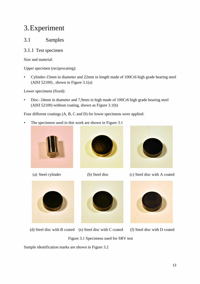
3.1.1 Test specimen
Size and material:
Upper specimen (reciprocating):
• Cylinder-15mm in diameter and 22mm in length made of 100Cr6 high grade bearing steel
(AISI 52100) , shown in Figure 3.1(a)
Lower specimens (fixed):
• Disc- 24mm in diameter and 7,9mm in high made of 100Cr6 high grade bearing steel
(AISI 52100) without coating, shown as Figure 3.1(b)
Four different coatings (A, B, C and D) for lower specimens were applied:
• The specimens used in this work are shown in Figure 3.1
(a) Steel cylinder (b) Steel disc (c) Steel disc with A coated
(d) Steel disc with B coated (e) Steel disc with C coated (f) Steel disc with D coated
Figure 3.1 Specimens used for SRV test
Sample identification marks are shown in Figure 3.2

13
(a) (b)
Figure 3.2 Drawing of specimens and rules of specimens’ identification. (a) Disc; (b) Cylinder.
Surface roughness of the specimen with/without DLC coating was measured by WYKO-
NT1100-3D-surface profilometer. The results are listed in Table 3.1
Table 3.1 Surface roughness of cylinder and different discs
Test
specimen
Steel
cylinder
Steel
disc
A coated
disc
B coated
disc
C coated
disc
D coated
disc
Roughness
Ra, nm
94.18 176.16 130.69 178.58 183.39 107.77
Average of the three measurements is reported herein, Ra is the average roughness of the
surface profile.
3.1.2 Lubricants
Base oil:
PAO: PAO (poly-alpha olefin) is a synthetic hydrocarbon (Figure 3.3). Two viscosity grades
of PAO namely V50 and V120 were employed. PAO is often used in tribo tests due to
uniformity in chemical structure in comparison with mineral oils. This enables to obtain
samples with definite properties, which is beneficial for fundamental research. The
hydrocarbon chains are relatively uniform in comparison with those of mineral oils which
ensures repeatable results.

14
Figure 3.3 PAO chemical structures (eample) - dimers of oligomer from 1-decene.
(Reproduced from ref [26], page 2914, Scheme 1 (a))
Additives:
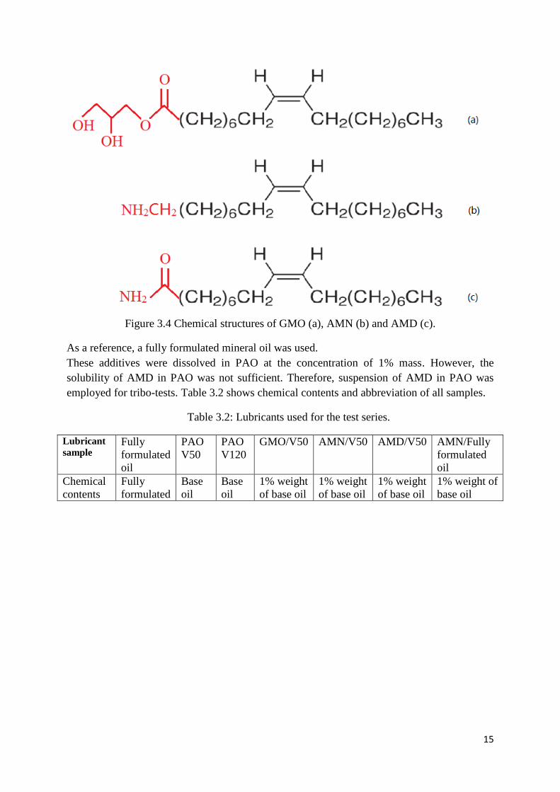
GMO: Glycerol mono-oleate-appears pasty solid as pure compound. The structural feature is
a straight hydrocarbon with one unsaturated bond and two hydroxyl groups at the terminal, as
shown in Figure 3.4 (a).
AMN: Oleyl amine - appears liquid as pure compound. Straight hydrocarbon with one
unsaturated bond and amino group at the terminal as shown in Figure 3.4 (b)
AMD: Oleyl amide - appears pasty solid as pure compound. Straight hydrocarbon with one
unsaturated bond and amide group at the terminal, as shown in Figure 3.4 (c)
They have the same alkenyl hydrocarbon (shown black) but difference in polar functional
group at the terminal (shown red).
15
Figure 3.4 Chemical structures of GMO (a), AMN (b) and AMD (c).
As a reference, a fully formulated mineral oil was used.
These additives were dissolved in PAO at the concentration of 1% mass. However, the
solubility of AMD in PAO was not sufficient. Therefore, suspension of AMD in PAO was
employed for tribo-tests. Table 3.2 shows chemical contents and abbreviation of all samples.
Table 3.2: Lubricants used for the test series.
Lubricant
sample Fully
formulated
oil
PAO
V50
PAO
V120
GMO/V50 AMN/V50 AMD/V50 AMN/Fully
formulated
oil
Chemical
contents
Fully
formulated
Base
oil
Base
oil
1% weight
of base oil
1% weight
of base oil
1% weight
of base oil
1% weight of
base oil

16
3.2 Test procedure.
3.2.1 Viscosity measurement
Viscosity of base oil was measured by Rheometer-Bohlin instrument, at 50゜C.
Table 3.3 Viscosity of sample lubricants
Lubricant sample Fully formulated
oil
PAO V 50
PAO V 120
Viscosity*(Pas)
at 50゜C
3.52E-02
2.22E-01
6.40E-01
3.2.2 Test matrix
Test matrix in Table 3.4 explains lubricants and tribo material combination.
Table 3.4 Different lubricants and tribo material system
Lubricant
coating system
Tribo material*
steel A coated B coated C coated D coated
Fully
formulated oil
X X X X X
PAO V50 X X X X X
PAO V120 X X
GMO(1)/PAO
V50
X X X X X
AMN(1)/PAO
V50
X X X X X
AMD(1)/PAO
V50
X X X X X
AMN(1)/Fully
formulated oil
X X
3.2.3 Tribo-test
An Optimol SRV-3 tester (Figure 3.5) was employed for evaluation of the tribological
properties of DLC-lubricant combinations, according to ASTM 6425. The outline of the test is
as follows. Sample lubricant (around 0.1 cm3) was applied on the flat surfaces by micropipette
and then a steel-cylinder was slid against DLC flat under reciprocating motion. Test duration
was 2 h at room temperature (22 – 26 °C). A stroke of 1 mm and a load of 48N
(corresponding to Hertz contact stress of 100 MPa) were employed. All parameters are shown
in Table 3.5. Friction coefficient was acquired using a data logger and computer.

17
(a) (b)
Figure 3.5 Optimol SRV-3 test instruments. (a) Without specimens; (b) With specimens.
Figure 3.5(b) shows the test configuration of the SRV test. During test process, the disc
specimen is clamped onto the lower specimen block. The upper cylindrical specimen is
loaded and oscillated back and forth by an electromagnetic drive along a small fixed angle
with axis against the stationery disc specimen shown as Figure 3.6 [27]. All the test were
conducted at a constant temperature of 50 C with maximum error of ± 0.5 C. The load is
applied on the cylinder via the load axle against the disc. The friction force is measured by
using a pair of piezoelectric force transducers. To minimize the edge effect, the cylinders
edges are rounded.
Figure 3.6 Description of friction test in SRV. (Reproduced from ref [27], page 4, Figure 3)
18
Table 3.5 Parameter values used in the SRV machine test cycle
Parameter Values Specimens
Frequency 50Hz
Load 48N
Contact Pressure 100MPa
Width deformation 0.218*10-4
m
Temperature 50 C
Stroke 1mm
Time 2 hour
3.3 Analysis of SRV test.
3.3.1 Friction trace
After the SRV test, the acquired data was processed and (1) average at steady state, (2)
fluctuation, (3) transition during running-in, were taken into account.
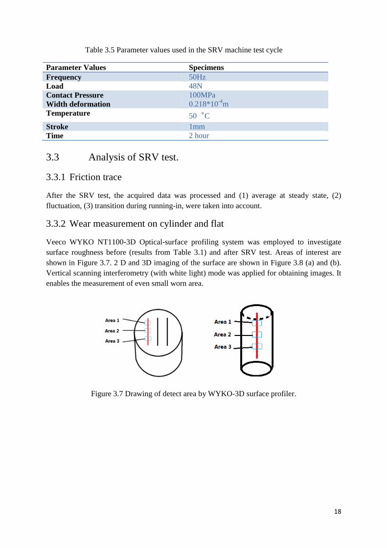
3.3.2 Wear measurement on cylinder and flat
Veeco WYKO NT1100-3D Optical-surface profiling system was employed to investigate
surface roughness before (results from Table 3.1) and after SRV test. Areas of interest are
shown in Figure 3.7. 2 D and 3D imaging of the surface are shown in Figure 3.8 (a) and (b).
Vertical scanning interferometry (with white light) mode was applied for obtaining images. It
enables the measurement of even small worn area.
Figure 3.7 Drawing of detect area by WYKO-3D surface profiler.

19
(a)
(b)
Figure 3.8 Image of B coated surface measured WYKO-3D surface profiler. (a) 2D image; (b)
3D image
3.3.3 Surface analysis
A scanning electron microscopy (SEM) (JSM-6460LV) with energy dispersive X-ray
spectrometry (EDS) (INCA Energy) was employed to obtain surface chemistry. The
analytical parameters are shown in Table 3.6.
Table 3.6 Parameter values used in the SEM/EDS investigation
Voltage of electron beam Topography magnifications High-resolution images,
25 KV in a raster scan pattern 10 times to more than
500,000 times
details less than 1 nm in size
EDS detects specific X-ray emitted by an accelerated electron from the sample. It detects
elements on the surface of 1 micrometer depth, if the thickness of the coating is thinner than 1

20
micrometer. It will also detects substrate steel as background.

21
4. Results
The tribological properties of DLC-flat with lubricant slid against steel-cylinder were
evaluated. Morphology and surface chemistry of the resultant worn surfaces were studied.
4.1 Steel flat (as reference)
4.1.1 Friction (SRV)
Figure 4.1 shows friction traces throughout the SRV test duration. The fully formulated oil
exhibited low friction with good repeatability. On the other hand, friction fluctuation was
observed for PAO with/without additives. Both PAO V50 and PAO 120 showed large
variations in friction. PAO V50 showed better friction than PAO V120 did at the steady state
(60 – 120 min). Therefore, the former was employed as base fluid for further experiments.
The additives changed the tribological properties of PAO V50 to some extent. As shown in
Figure 4.2, GMO and AMN reduced friction during the running-in period (0 – 60 min), while
they showed higher friction than PAO V50 did after 60 min. AMD gave poor repeatability in
friction. Figure 4.3 shows average friction and deviation during 60 – 120 min. The fully
formulated oil showed low friction with low fluctuation.
Figure 4.1 Variation of the friction coefficient with time for steel cylinder and steel disc from
SRV test. Three colours of curves represent three kinds of lubricant base oils, PAO V50 (red),
PAO V120 (blue), fully formulated oil (black).

22
Figure 4.2 Variation of the friction coefficient with time for steel cylinder and steel disc from
SRV test. The four colours of curves represent base oil PAO V50 (black), GMO/PAO V50
(red), AMN/PAO V50 (blue) and AMD/PAO V50 (green).
Figure 4.3 Summary of friction coefficients with different lubricants used in steel-steel
contact SRV tests. The value is presented as average of at least two tests.
4.1.2 Morphology of worn surface (SEM)
Figure 4.4 shows SEM microphotograph at the magnification of 250 times. Material transfer,
probably from the counter cylinder was observed for PAO V50, as marked on the figure.

23
(a) (b) (c)
Figure 4.4 SEM micrograph of the wear scar on steel disc at the magnification of 250 times
lubricated with PAO V50, PAO V120 and full formulated oil. (a) PAO V50, (b) PAO V120
(c) fully formulated oil.

24
4.2 A-coated flat
4.2.1 Friction (SRV)
As shown in Figure 4.5 PAO V50, PAO V120, and full formulated oil exhibited similar
friction traces: Friction coefficient was between 0.15 – 0.20 throughout the test without
obvious running-in period. Figure 4.6 shows the effect of additives on friction. AMN reduced
friction after 5 min. of running-in. GMO showed a running-in period of 40 min. Both AMN
and GMO improved the tribological properties of PAO V50 at the steady state. Although
AMD showed some improvements, the repeatability of friction was not good.
Figure 4.7 shows average friction at the steady state for A-coated flat. GMO in PAO V50 and
AMN in PAO V50 showed better tribological properties than fully formulated oil.
Figure 4.5 Variation of the friction coefficient with time for steel cylinder and A coated steel
disc from SRV test. Three colours of curves represent three kinds of lubricant base oils, PAO
V50 (black), PAO V120 (red), fully formulated oil (blue).

25
Figure 4.6 Variation of the friction coefficient with time for steel cylinder and A coated steel
disc from SRV test. Four colours of curves represent base oil PAO V50 (black) and V50 with
three kinds of additives GMO/PAO V50 (red), Amine/PAO V50 (blue) and Amide/PAO V50
(green).
Comparison of the average value for friction coefficient after one hour running is shown in
Figure 4.7. Lubricants with additives perform better than the base oil. GMO and AMN
showed the best results. Repeatability with them is much better than AMD additive.
Figure 4.7 Summary of friction coefficients with different lubricants used in Steel-A coated
steel contact SRV tests. The value is presented as average of at least two tests.
4.2.2 Morphology of worn surface (SEM)

26
Figure 4.8 shows microphotograph by SEM at the magnification of 250 times. Contrary to the
worn surface of steel (Figure 4.4), the surface looks smooth. Also the grinding marks still
remained on the worn surfaces for PAO V50 and AMN in PAO V50. From these observations,
wear on A-coated flat is considered low.
(a) (b)
Figure 4.8 SEM micrograph of the wear scar on A coated steel disc at the magnification of
250 times lubricated with PAO V50 and AMN/V50: (a) PAO V50, (b) AMN/V50.
27
4.3 B-coated flat
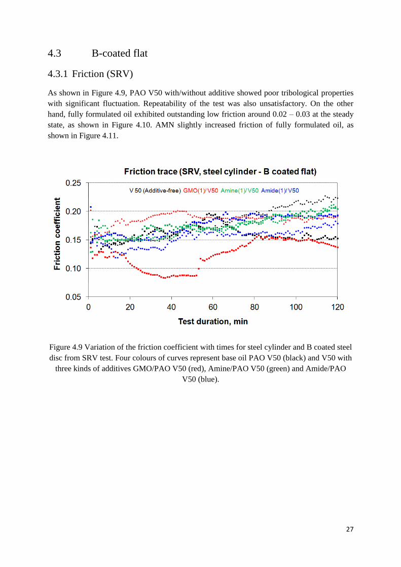
4.3.1 Friction (SRV)
As shown in Figure 4.9, PAO V50 with/without additive showed poor tribological properties
with significant fluctuation. Repeatability of the test was also unsatisfactory. On the other
hand, fully formulated oil exhibited outstanding low friction around 0.02 – 0.03 at the steady
state, as shown in Figure 4.10. AMN slightly increased friction of fully formulated oil, as
shown in Figure 4.11.
Figure 4.9 Variation of the friction coefficient with times for steel cylinder and B coated steel
disc from SRV test. Four colours of curves represent base oil PAO V50 (black) and V50 with
three kinds of additives GMO/PAO V50 (red), Amine/PAO V50 (green) and Amide/PAO
V50 (blue).

28
Figure 4.10 Variation of the friction coefficient with time for steel cylinder and B coated steel
disc from SRV test. Three colours of curves represent base oil PAO V50, fully formulated oil
(blue) and AMN/ fully formulated oil (red).
Figure 4.11 Summary of friction coefficients with different lubricants used in Steel-B coated
steel contact SRV tests. The value is presented as the average of at least two tests.
4.3.2 Wear (3D profilometer)
Figure 4.12, shows a 3D image of the wear surface and width of the wear scar. Figure 4.13
shows width on both flat and cylinder after the SRV test. PAO V 50 with/without additive
gave wear scar more than 300 micro-meters wide. Among the additives, only GMO reduced

29
wear to some extent. It also reduced wear on cylinder, however repeatability was not
satisfactory. Average wear by fully formulated oil was lower than that by PAO V50 based oils.
When AMN was added to fully formulated oils, it improved repeatability of wear but the
average was still at the same level as the fully formulated oil.
Figure 4.12 3D image of wear surface and 2D measurement. a-3D image for B-coated flat
lubricated with GMO/V50, b-2D measurement for B-coated flat lubricated with GMO/V50, c-
3D image for B-coated flat lubricated with fully formulated oil, d-2D measurement for B-
coated flat lubricated with fully formulated oil

30
Figure 4.13 Average width of wear scar on steel cylinder and B coated disc lubricated in PAO
V50, AMN/V50, GMO/V50, AMD/V50, Fully formulated and AMN/fully formulated oil
measured by WYKO 3D surface profiler.
4.3.3 Morphology and chemistry of worn surface (SEM/EDX)
Figure 4.14 shows morphology (the magnification of 250 times) and surface chemistry of
worn surfaces lubricated by fully formulated oil with/without AMN additive. Similar to the
worn surface on A-coated flat, the grinding marks still remained on the worn surfaces. Some
grinding marks on the worn surface of the cylinder with AMN (Figure 4.13(d)) were found,
while those without AMN (Figure 4.13 (c)) were not clear. These results indicate a certain
effect of AMN in reducing wear.
Figure 4.15 shows contents of element on non-coated (base material) and on B-coated flats.
The base material is composed of Fe as the major element. Also detectable amount of C, Si,
and Cr were found. As DLC, high content of C on B-coated flat is reasonable. A considerable
amount of Ti on B-coated flat was found. This is an additive (or so-called doped element) of
DLC
Figure 4.16 and Figure 4.17, show element contents on non-rubbed surface and on rubbed
surface, respectively. On both surfaces, C and Fe are the major elements. Ti and Al were also
found. Since the detection depth of SEM-EDX under these conditions was around 1 micro-
meter, a considerable amount of Fe indicates that the thickness of DLC was less than 1 micro-
meter. Figure 4.18 shows the differences in element contents before and after SRV testing. It
clearly shows increase in Fe content as well as decrease in C content. The latter can be
understood by wear of DLC by rubbing. As the results, relative contents of Fe increased.
Another mechanism of increase in Fe can be transfer from the cylinder surface by rubbing.

31
(a) (b)
(c) (d)
Figure 4.14 SEM micrograph of the wear scar of steel cylinder and B coated disc at the
magnification of 250 times lubricated with fully formulated oil and AMN/ fully formulated oil.
(a) Disc lubricated by fully formulated oil, (b) Disc lubricated by AMN/ fully formulated oil,
(c) Cylinder lubricated with fully formulated oil, (d) Cylinder lubricated with AMN/ fully
formulated oil

32
Figure 4.15 The major elemental constituents for steel disc and B coated disc. Steel disc (left)
and B coated disc (right)
Figure 4.16 SEM micrograph of the wear scar of B coated disc at the magnification of 75
times lubricated with fully formulated oil and the corresponding EDS spectrum of the worn
surface of the B coated disc. EDS spectrum was obtained from the square area out of wear
scar marked on the SEM micrograph.

33
Figure 4.17 SEM micrograph of the wear scar of B coated disc at the magnification of 75
times lubricated with fully formulated oil and the corresponding EDS spectrum of the worn
surface of the B coated disc. EDS spectrum was obtained from the square area in wear scar
shown in the SEM micrograph.
Figure 4.18 Element content on B coated flat of non-rubbed surface and rubbed surface.
Figure 4.19 shows electron images and chemical mapping of surfaces. On the non-rubbed
surface, rich in C around the grinding marks is shown by chemical mapping. The existence of
Fe and Ti seems uniform on the surface. Slightly lower contents of C as well as considerably
higher contents of Fe on the worn surface are shown by chemical mapping. On the other hand,
there are no obvious differences in Ti contents on the mapping. The results are in good
correspondence with the results of Figure 4.18. It should be noted that Ti remained on the
surface after rubbing.

34
(a) (b)
Figure 4.19 SEM/EDS chemical mapping around worn surface (a) and part of wear scar (b)
on B coated disc. Electron image (top), C (bottom left), Ti (bottom middle), Fe (bottom right)
The remaining grinding marks after rubbing is clear (Figure 4.20). Almost no changes in C
contents on the surface before and after rubbing lubricated with AMN in fully formulated oil
(Figure 4.21). These results indicate the wear reducing effect of AMN for B-coating.
Figure 4.20 SEM micrograph of the wear scar of B coated disc at the magnification of 250
times lubricated with AMN/ fully formulated oil and the corresponding EDS spectrum of the
worn surface of the B coated disc. EDS spectrum was obtained from the square area in the
wear scar shown in the SEM micrograph.

35
Figure 4.21 Element content on B coated flat of non-rubbed surface and rubbed surface
lubricated with Amine/fully formulated oil.

36
4.4 C-coated flat
4.4.1 Friction (SRV)
The tribological properties of C-coated flat were analogous to those of B-coated flat. Figure
4.22 shows friction traces for C-coated flat, which has less fluctuation in friction in
comparison with Figure 4.9. The similarity was also observed for fully formulated oil, as
shown in Figure 4.23. It should be noted that, friction coefficient for C-coated flat with fully
formulated oil was below 0.02 in the steady state, which is lower than that for B-coated flat.
AMN as additive improved the running-in process of fully formulated oil for C-coated flat. As
shown in Figure 4.23, friction decreases but not stable for fully formulated oil during 0 – 25
min. of SRV test. Then it slowly decreased to low friction within 70 – 80 min. of test duration.
On the other hand, AMN + fully formulated oil (Figure 4.24) showed quick running-in period
(less than 20 min.) with good repeatability. Similar to B-coated flat, AMN increased friction
coefficient for C-coated flat with fully formulated oil.
Figure 4.22 Variations of the friction coefficient with time for steel cylinder and C coated
steel disc from SRV test. Four colours of curves represent base oil PAO V50 (black) and V50
with three kinds of additives GMO/PAO V50 (red), AMN/PAO V50 (blue) and AMD/PAO
V50 (green).

37
Figure 4.23 Variations of the friction coefficient with time for steel cylinder and C coated
steel disc from SRV test. Three colours of curves represent base oil PAO V50 (black), fully
formulated oil (blue) and AMN/ fully formulated oil (red).
Figure 4.24 Summary of friction coefficients with different lubricants used in Steel-C coated
steel contact SRV tests. The value is presented as the average of at least two tests.
4.4.2 Wear (3D profilometer)
Figure 4.25, shows 3D image of wear surface and width measurement of wear scar.Figure
4.26, shows wear width on cylinder and C-coated flat after SRV testing. Compared to the
results of B-coated flat (Figure 4.13), repeatability is better. It should be noted that AMN
decreased wear of C-coated flat.

38
Figure 4.25 3D image of wear surface and 2D measurement. a-3D image for C-coated flat
lubricated with GMO/V50, b-2D measurement for C-coated flat lubricated with GMO/V50, c-
3D image for C-coated flat lubricated with fully formulated oil, d-2D measurement for C-
coated flat lubricated with fully formulated oil
Figure 4.26 Average width of wear scar on steel cylinder and C coated disc lubricated in PAO
V50, AMN/V50, GMO/V50, AMD/V50, fully formulated oil and AMN/ fully formulated oil
measured by WYKO 3D surface profiler.

39
4.4.3 Morphology and chemistry of worn surface( SEM/EDX)
Figure 4.27 shows that wear on both cylinder and C-coated flat is low. Figure 4.28-4.29 show
contents of elements on C-coated flat. The results are quite similar to those for B-coated flat,
as expressed above. The results also show almost no change in C contents on the surface
before and after rubbing lubricated with AMN in full formulated oil (Figure 4.21). These
results suggest the wear reducing effect of AMN for B-coating.
(a) (b)
Figure 4.27 SEM micrograph of the wear scar of steel cylinder and C coated disc at the
magnification of 250 times lubricated with fully formulated oil. (a) Disc lubricated by fully
formulated oil, (b) Steel cylinder lubricated by fully formulated oil.
Figure 4.28 SEM micrograph of the wear scar of C coated disc at the magnification of 75
times lubricated with fully formulated oil and the corresponding EDS spectrum of the worn
surface of the C coated disc. EDS spectrum was obtained from the square area in the wear
scar shown in the SEM micrograph.

40
Figure 4.29 Element content on C coated disc of the non-rubbed surface and rubbed surface.
Figure 4.30 SEM/EDS chemical mapping of the wear scar area on C coated disc. Electron
image (top), C particle (bottom left), Ti particle (bottom middle), Fe particle (bottom right)

41
Figure 4.31 SEM micrograph of the wear scar of C coated disc at the magnification of 250
times lubricated with AMN/ fully formulated oil and the corresponding EDS spectrum of the
worn surface of the C coated disc. EDS spectrum was obtained from the square area in wear
scar shown in the SEM micrograph.

42
4.5 D-coated flat
4.5.1 Friction (SRV)
As shown in Figure 4.32 – 4.34, PAO V50 with/without additive exhibited high friction with
fluctuation. Fully formulated oil provided stable friction around 0.15 throughout the SRV test.
Figure 4.32 Variation of the friction coefficient with time for steel cylinder and D coated steel
disc from SRV test. Four colours of curves represent base oil PAO V50 (black), GMO/V50
(red), AMN/V50 (blue) and AMD/V50 (green).

43
Figure 4.33 Variation of the friction coefficient with time for steel cylinder and D coated steel
disc from SRV test. Two colours of curves represent base oil PAO V50 (black), and fully
formulated oil (blue).
Figure 4.34 Summary of friction coefficients with different lubricants used in Steel-D coated
steel contact SRV tests. The value is presented as average of at least two tests.
4.5.2 Wear (3D profilometer)
Figure 4.35, shows 3D image of worn surface and width of wear scar. As shown in Figure
4.36, fully formulated oil exhibited good anti-wear properties. Wear scar was visible with the

44
naked eye. However, it was under the detection threshold of the 3D profilometer.
Figure 4.35 3D image of the wear surface and 2D measurement. a-3D image for C-coated flat
lubricated with GMO/V50, b-2D measurement for C-coated flat lubricated with GMO/V50, c-
3D image for C-coated flat lubricated with fully formulated oil, d-2D measurement for C-
coated flat lubricated with fully formulated oil

45
*no repeatbility
Figure 4.36 Average width of wear scar on steel cylinder and D coated disc lubricated in PAO
V50, AMN/V50, GMO/V50, AMD/V50, fully formulated oil measured by WYKO 3D
surface profiler.
4.5.3 Morphology of worn surface (SEM)
SEM detects the wear scar on D-coated flat which was impossible by 3D profiometer, as
shown in Figure 4.37. A pad-like surface inside wear track suggests a boundary film.
Figure 4.37 SEM micrograph of the wear scar for D coated disc lubricated with fully
formulated oil.

46
5. Discussion
The mechanism of low friction for B-coated flat was investigated by tracing the changes in
surface roughness on flat as a function of test duration (Figure 5.1). As shown in Figure 2.6(a),
the original (non-rubbed) B-coated flat has a surface roughness of Ra 178.58nm. The wear
scar became obvious with increased test duration (Figure 5.2). Figure 5.3 shows line profile
parallel with the sliding direction (X) and intersecting to the sliding direction (Y).
Smoothening of the surface by the tribological process was observed. Table 5.1 shows surface
roughness, wear width, and friction coefficient for B-coated and D-coated flats. Both
extension of contact area and smoothening of surface are beneficial to shift the lubrication
regime from mixed to hydrodynamic (Figure 1.2).
Figure 5.1 Variations of the friction coefficient with times for steel cylinder and B coated
steel disc from SRV test lubricated with full formulated oil.
(a) (b) (c)
Figure 5.2 3D topography of B coated discs. (a) 1minute running; (b) 6 minutes running; (c)
15 minutes running

47
Figure 5.3 Changes in roughness in X, Y direction as test duration of SRV for steel cylinder
and B coated flat lubricated with fully formulated oil.
Table 5.1 Friction coefficients, roughness and wear width for B- and D-coated steel disc
lubricated with fully formulated oil
Time B coated disc D coated disc
0min μ=0.16
Ra=179nm
Wear width=0
μ=0.15
Ra=108nm
Wear width=0
2hours μ=0.04
Ra (X profile)=100nm
Ra (Y profile)=20nm
Wear width=307um
μ=0.15
Ra (X profile)=230nm
Ra (Y profile)=180nm
Wear width=143um
The lowest friction was obtained with fully formulated commercial oil, which was selected as
a reference. However, the running-in period to reach the steady state and repeatability of
friction for C-coated flat seemed to be improved. When AMN was added, these were
improved, as shown in Figure 4.23. The running-in period for C-coated flat by fully
formulated oil (40 min) was reduced to 10 min by the addition of AMN. The smoothing effect
of AMN was also observed, as shown in Figure 5.4. The quick running-in period with AMN
suggests a preferred interaction of AMN in comparison with the other additives in fully
formulated oil.

48
Figure 5.4 3D image and SEM micrograph of the wear scar of C coated disc at the
magnification of 250 times lubricated with fully formulated oil and AMN/fully formulated oil.

49
6. Conclusions
Figure 6.1 Average values of friction coefficients with the different tribological system after 1
hour SRV test.
In this thesis work, the combinations of DLC with lubricants were evaluated. An optimal
combination of coating-lubricant to enhance performance has been found. The friction
behaviour has been researched experimentally by over one hundred runs of SRV tests that
summarized in Table 6.1 and Figure 6.1. SEM/EDS have been used to investigate surfaces
before and after test, partly summarized in Table 6.2.

50
Table 6.1 Material-lubricant combination for improved tribological performances.
Material
Steel DLC
Hydrogen-free,
sp3-rich
Hydrogenated,
sp2 /sp
3 mixed
Surface
finish
Surface
unfinished
WC-added Cr-added
Lubricant PAO Acceptable Poor
PAO+
Friction
Modifier
Fully
formulated
oil
Excellent
μ=0.025
Trunning-
in=20min
W=308µm
Excellent
μ=0.016
Trunning-
in=40min
W=228µm
Acceptable
μ=0.164
W-
undetectable
Acceptable
μ=0.151
W=128µm
Fully
formulated
oil+Amine
Excellent
μ=0.02
Trunning-
in=5min
W=264µm
Excellent
μ=0.034
Trunning-
in=10min
W=214µm
Not
examined
Not
examined

51
Table 6.2 Physical/Chemical properties of DLC surface for improved tribological
performances.
State Tribological
properties
Non-rubbed Rubbed
D
L
C
Hydrogen-
free, sp3-rich
Surface
finish
Element Fe (62%)
C (28%)
Ti (6%)
Fe (74%)
C (17%)
Ti (5%)
Excellent
Surface
roughness
Ra 179nm
Surface
unfinished
Element Fe (53%)
C (37%)
Ti (6%)
Fe (77%)
C (14%)
Ti (5%)
Surface
roughness
Ra 183nm
Hydrogenated,
sp2 /sp
3 mixed
WC-
added
Surface
roughness
Ra 131nm
undetectable Acceptable
Cr-added Surface
roughness
Ra 108nm
52
Tentative conclusions of this work are as follows:
The combinations of coating B and coating C with commercial fully formulated
mineral oil showed extremely low friction and slightly low wear in comparison with
other material-lubricant combinations.
Oleylamine increased friction for B- and C- coating with fully formulated oil. It
improved running-in process and anti-wear properties for the material-lubricant
combinations.
Surface smoothing combined with decreasing in contact pressure was proposed as
mechanism of low friction for B- and C- coating with fully formulated oil.
Friction modifiers in PAO have no obvious friction reduction effect for A-, B-, C-
coating, while it improved steel and coating D to some extent.
53
7. References
[1] Jost J.P., Education and Research Her Majesty’s Stationary Office, Lubrication (Tribology)
1966, p 3-4
[2] Nilsson D. Tribology of hydraulic motor. Luleå: Luleå University of Technology; 2009.
Licentiatavhandling Luleå : Luleå tekniska universitet, 2009. ISBN 978-91-7439-311-8
[3] Stribeck R. , Die wesentlichen Eigenschaften der Gleit- und Rollenlager (The basic
properties of sliding and rolling bearings), Zeitschrift des Vereins Deutscher Ingenieure, 2002,
Nr. 36, Band 46, p 1341-1348.
[4] Spikes, H.A., Film-Forming Additives-Direct and Indirect Ways to Reduce Friction,
Lubrication Science, Volume 14, Issue 2, pages 147-167, February 2002, DOI:
10.1002/ls.3010140204
[5]Podgornik B., Hren D., Vizintin J., Jacobson S., Stavlid N., Hogmark S., Combination of
DLC coatings and EP additives for improved tribological behavior of boundary lubricated
surfaces, Wear 261 (2006) 32–40
[6] Holmberg K., Matthews A. Coatings tribology: properties, techniques, and applications in
surface engineering. Amsterdam: Elsevier; 1994. P 55-57
[7] Luo, D.B. Fridrici. V, Ph. Kapsa, A systematic approach for the selection of tribological
coatings, Wear 271 (2011) 2132– 2143
[8] Holmberg K., Matthews A. Coatings tribology : properties, techniques, and applications in
surface engineering. Amsterdam: Elsevier; 1994, p 12-19
[9] Mo, J.L, Zhu, M.H. Tribological oxidation behaviour of PVD hard coatings, Tribology
International 42 (2009) 1758–1764
[10] Nilsson D., Prakash B.. , Influence of different surface modification technologies on
friction of conformal tribopair in mixed and boundary lubrication regimes, Wear
273(2001)75-81
[11] Miyake S. , Takahashi S., Watanabe I. , and Yoshihara H., Friction and Wear Behavior
of Hard Carbon Films, Tribology Transactions, 30, 1, 121-127
[12] Aisenberg S, Chabot R. Ion-beam deposition of thin films of diamond-like carbon.
Journal of Applied Physics, 1971; 42: 2953–8.
[13] Vengudusamy B., Mufti R., Lamb G. D., JonathanH.Green, Hugh A.Spikes, Friction
properties of DLC/DLC contacts in base oil, Tribology International 44 (2011) 922–932
[14] Delarney G., Arps J.H. Biomedical applications of diamond-like carbon (DLC) coatings:
A review. Surface and Coatings Technology. 2005; 200(7):2518-2524
[15] Renondeau H, Taylor R I, Smith G C, and Torrance A A, Friction and wear performance
of diamond-like carbon and Cr-doped diamond-like carbon coatings in contact with steel
surfaces, Journal of Engineering Tribology March 1, 2008 vol. 222, No. 3 231-240
[16] Miyake S., Saito T., Yasuda Y., Okamoto Y., Kano M.. Improvement of boundary
lubrication properties of diamond-like carbon (DLC) films due to metal addition, Tribology
International 37 (2004) 751–761
[17] Erdemir A. and Fenske G. R., Tribological Performance of Diamond and Diamond like
Carbon Films at Elevated Temperatures, Asle Transaction, 39(1996),4,787-794
[18] Mang T., Dresel W. Lubricants and lubrication. 2nd ed.Weinheim: Wiley-VCH; 2007,
Toxicology 123:217–226

54
[19] Rudnick L.R. Lubricant additives: chemistry and applications. New York: Marcel
Dekker; 2003, p 1-27
[20] Minami I. , Mori S. , Concept of molecular design towards additive technology for
advanced lubricants, Lubrication Science, 2007, 19 (2), 127-149.
[21] Bhushan B. Introduction to tribology. New York: Wiley; 2002, p 170-177
[22] Kovalchenko A., Ajayi O. O., Erdemir A., and Fenske G. R., Friction and Wear
Performance of Low-Friction Carbon Coatings under Oil Lubrication, Manuscript of paper to
be presented at 2002 SAE Future Car Congress, Arlington, VA, June 3-5, 2002
[23] Kano M., Yasuda Y., Okamoto Y., Mabuchi Y., Hamada T., Ueno T., Ye J., Konishi S.,
Takeshima S., Martin J.M., De Barros Bouchet M.I., and Le Mogne T., Ultralow friction of
DLC in presence of glycerol mono-oleate (GMO), Tribology Letters, February 2005 (2005),
Vol. 18, No. 2
[24] Minami, I., Kubo T., Nanao H., Mori S., Sagawa T., Okuda S. , Investigation of Tribo-
Chemistry by Means of Stable Isotopic Tracers, Part 2: Lubrication Mechanism of Friction
Modifiers on Diamond-Like Carbon, Tribology Transactions, 50:4, 477-487, 2007
[25] De Barros Bouchet M. I., Matta C., Le-Mogne Th., Michel Martin, J., Sagawa T., Okuda
S. and Kano M., Improved mixed and boundary lubrication with glycerol-diamond
technology, Tribology letters, 2007 VOL 1 NO 1 No 1, 28-32
[26] Huang, Q. G., Chen, Li. G., Ma, L., Fu, Z. F., Yang, W. T, Synthesis and characterization
of oligomer from 1-decene catalyzed by supported Ziegler-natta catalyst, European Polymer
Journal 41 (2005) 2909-2915.
[27] ASTM Internation, Standard Test Method for Measuring Friction and Wear Properties of
Extreme Pressure (EP) Lubricating Oils Using SRV Test Machine (2010), D6425-05.

55
Appendices
1. Lubricant preparation
Sample lubricants were prepared as the following requirement.
Lubricant base oil PAO V50 (>40ml), pure GMO (0.1g), AMN (0.1g), AMD (0.1g),
aluminium foil
Lab ware: 3 Beakers (80 cm3), 4 bottles, 2 Spatulas, 4 Micropipet, 4 Microinjector, Micro-
balance (0.1mg - 1000g)
Procedure:
Put one empty 80ml beaker on micro-balance.
Wait it for stable and set zero for the balance.
Use spatulas (for AMD) or micropipette (for GMO and AMN) to put 0.1g of additive in the
beaker.
Then put 9.9g PAO V50 base oil into the beaker using micropipette.
Use aluminium film to make a cover on the top of beaker.
Ultrasonic dispersed at c.a 50°C for more than 5 min until clear solution.
Transfer the prepared lubricant into new bottle with microinjector, print a label for the bottle
and microinjector.

56
2. Viscosity measurement
Viscosity measurement was performed by the following procedure:
a. Preparation:
Cleaning solvents and disposal: Petroleum ether 10 ml, Paper towel, Lab gloves
Lab ware: 1 Beakers (80cm3), Tweezer, Petri dish, Micropipet
Samples: Shell Tellus S 68 10 ml, PAO V50 10 ml, PAO V120 10 ml.
b. Start the system.
1. Start cooling system, turn on computer, instrument of rheometer and attached
temperature unit control boxes.
2. Press the up arrow shaped button on the instrument panel, until the rising process
finishedart the initialisation.
3. Begin initialisation and make the software working.
c. Selecting the correct geometry.
In this experiment cup and bob-the concentric cylinder measuring geometry, C25
Cup diameter were employed of 27.5mm, and bob diameter of 25mm, bob height of 37.5mm,
immersion depth of 12.4, cone angle 15°
d. Making adjustment to set the correct gap
Choose CP 4/40 (a Cone with a 4° angle and having a diameter of 40 mm)
1. Make one of the flats faces the front by turning the chuck.
2. Move the air bearing lock to the left and loosen the chuck.
3. Insert the upper geometry, and then push the geometry up into the chuck to reach the
top, tighten the chuck at that position.
4. Slide the air bearing lock to the right, chuck could free whirling.
5. Insert the 4/40 Cone into the rheometer, and never forget to ensure the chuck lock is in
the locked position
6. Press zero on the front instrument panel and then the up arrow shaped button.
7. Geometry move up slowly, choose correct geometry from the software to set the
required gap 0.15mm.
8. Press the Down button to reach to gap, GAP light on control panel switches off and
the OK light switches on.
e. Sample loading
8. Use industry petrol to clean the cup and bob.
9. Place about 5ml sample oil Shell 68 in the cup.
10. Press the down arrow shaped button on the instrument panel, lower the upper bob into cup
slowly. Until sample oil slightly over fill and then use micropipet to trim off any excess
sample.
f. Software settings
1. Click the Viscometry button in the Bohlin software and then choose the measuring
system.
2. Select program parameter like shear stress, normal stress level.
3. Choose temperature control mode, at 50 °C half the hour
g. Starting a test
1. Recheck air bearing lock to make sure it is not on click the Start button.
2. Click the Start button.

57
h. Closing processes
1. Data automatically continue coming, save data result directly when experiment finish.
2. Lift the upper bob clear of the lower one.
3. Remove the geometries from the instrument and clean
4. Shutting down all the instruments related with system

58
3. SRV test procedure
All the ASTM D6425-05 SRV tests follow the process like this:
Procedure A: Samples preparation
Specimen: Cylinder (Φ15X22 mm), Flat (Φ24X7.9 mm), Lubricant: > 0.5 cm3
Instruments: 2 Beakers (80 cm3), Petri dish, Tweezers, Micropipet, Wrench, Screwdriver
Cleaning solvents and disposal: Petroleum ether (40 cm3), Acetone (30 cm
3), Paper towel,
Lab gloves
Procedure B: Cleaning
Attention: Handle organic solvents in a hood. Handle specimen using tweezers.
Put specimen and petroleum ether (30 cm3) in a beaker.
Clean in Bandelin Sonorex ultrasonic for 5 min.
Replace petroleum ether by acetone (30 cm3).
Clean in Bandelin Sonorex ultrasonic for 5 min.
Move the specimen to a petri dish and dry in air.
Wipe the cylinder holder with paper towel soaked with petroleum ether and dry in air.
Procedure C: Sample setting
Turn on the machine, log on the computer.
Ensure the machine is unloaded.
Install the flat specimen.
Place the cylinder specimen in the holder and tight the fastening screw loosely.
Install the holder.
Apply a load of 10 N; loosen the fastening screws on both flat and cylinder holders.
Increase the load to 50 N and tighten them again (With a torque wrench to 2.2 to 2.5 Nm is
better).
Place 0.1 cm3 of lubricant to the contact using a micropipet and release the load.
Procedure D: Measurement
Confirm the parameters on the software and temperature of heater controller.
Click the start command on the computer.
When the temperature has stabilized, click the run command on the computer.
Procedure E: Cleaning
After the measurement has finished, the machine will be automatically stopped.
Save the digital data of the measurement on computer.
Export the digital data of the measurement on USB memory as ASCII format.
After the temperature has cooled to room temperatures, disassemble the specimen.
Log off the computer and turn off the machine.
Clean specimen with paper towel soaked with petroleum ether.
Clean specimen holders with paper towel soaked with petroleum ether.
Clean tools and work area.

59
4. Wear measurement by 3D-profiler
Wear measurement was performed by the follow in procedure:
1. Place the disc or roller on the stage, make sure the surface is clean and free of dust.
2. Install the 10X magnification objective.
3. Install the 1X FOV lens.
4. On the left side of the measurement head there is a filter selector level, place it to
cental position which is the VSI filter.
5. Open software Wyko Vision 32
6. Click the Open Mesaurement Options button.
7. Select the suitable objective and FOV
8. Click the Intensity button to Open the Intensity window.
9. Make adjustment for the intensity. Use the intensity knob on the front of the
equipment to increase the intensity if the screen is dark. Lower the intensity if some
red points appear, until all the red points just disappear.
10. Remove the sample until the part of wear on the surface is visible in the field of view.
11. Make sure the fringers are focused on the top of the step.
12. Wait the system stable for a while.
13. Click the New Measurement button.
14. Analysis data, measure wear width and depth, the roughness of wear scar.

60
5. Lubricant base oil- PAO
PAO V50 and V120 are supplied by Idemitsu Kosan Co Ltd. With its own metallocene
catalyst technology and unique molecular structure control technology, Idemitsu Kosan has
developed a high-performance PAO. Features are: 1.High viscosity index, 2.Low pour point,
3.Low viscosity at low temperature, 4. High oxidation stability. It can be used such as gear oil
for wind power generation and automobile where both durability and high-efficiency are
required. (Reference: http://www.idemitsu.com/company/news/2010/100907.html) V50 and
V120 are different in viscosity; Table 5.1shows physical properties.
Table 5.1 Physical properties of PAO V50 and V120
PAO V50 PAO V120
Kinematic Viscosity (mm2/s) 40°C 425 1250
Kinematic Viscosity (mm2/s) 100°C 50 127
Viscosity Index 180 207
Pour Point (°C) -45 -40


![Tribological performance of hybrid filtered arc …nanoproductengineering.com/papers/Tribo_paper_part_II_SCT_V201-14... · selected as the primary coating substrate [10,11]. Pyrowear](https://img.pdfslide.net/doc/110x75/5b93cd5809d3f2012e8bf7c0/tribological-performance-of-hybrid-filtered-arc-na-selected-as-the-primary-coating.jpg)