Embed Size (px)
Citation preview

Final
Acoustic Monitoring Plan
TRIDENT SUPPORT FACILITIES
EXPLOSIVES HANDLING WHARF (EHW-2)
NAVAL BASE KITSAP at BANGOR
SILVERDALE, WA
July 2012
DEPARTMENT OF THE NAVY


TRIDENT Support Facilities Explosives Handling Wharf
Final Acoustic Monitoring Plan i
TABLE OF CONTENTS
1.0 INTRODUCTION............................................................................................................................ 1
2.0 OBJECTIVES OF ACOUSTICAL MONITORING FOR EHW-2 ................................................ 3
3.0 PROJECT AREA ............................................................................................................................ 5
4.0 PILE INSTALLATION LOCATION ............................................................................................. 5
5.0 PILE INSTALLATION METHODS ............................................................................................... 5
6.0 ACOUSTIC MONITORING METHODS .................................................................................... 10
7.0 SIGNAL PROCESSING ................................................................................................................ 26
8.0 ANALYSIS ..................................................................................................................................... 26
9.0 REPORTING ................................................................................................................................. 26
10.0 REFERENCES .............................................................................................................................. 27
LIST OF APPENDICES
A Calculation of Cumulative SEL
LIST OF FIGURES
Figure 1. Vicinity Map ............................................................................................................................... 2 Figure 2. EHW-2 Action Area .................................................................................................................... 6 Figure 3. Proposed EHW-2 Location .......................................................................................................... 7 Figure 4. NBK at Bangor Restricted Areas with Project Area Highlighted .................................................. 8 Figure 5. NBK at Bangor Bathymetry and Topographic Relief ................................................................. 12 Figure 6. Underwater and Airborne Acoustic Monitoring Locations .......................................................... 13 Figure 7. Toandos Floating Raft with Hydrophones .................................................................................. 16
LIST OF TABLES
Table 1. Examples of Equipment Used in Acoustic Sound Monitoring..................................................... 22

TRIDENT Support Facilities Explosives Handling Wharf
ii Final Acoustic Monitoring Plan
This page is intentionally blank.

TRIDENT Support Facilities Explosives Handling Wharf
Final Acoustic Monitoring Plan 1
1.0 INTRODUCTION
This Acoustic Monitoring Plan (Plan) provides a protocol for conducting airborne and
hydroacoustic measurements of pile-driving operations during the initial construction period of
the second Explosives Handling Wharf (EHW-2) at Naval Base Kitsap (NBK) at Bangor,
Washington. This Plan was developed to support the respective Biological Assessment (BA) and
Incidental Harassment Authorization (IHA) compliance documents for this project (NAVFAC
2011a; 2011b). Both sets of documents provide a more in-depth discussion on the modeling
assumptions and calculations for the project and are incorporated here by reference. There are
multiple acoustic measurement objectives, which are described in more detail below.
The EHW-2 project will be constructed at NBK at Bangor, Washington. NBK at Bangor is
located on Hood Canal approximately 20 miles due west of Seattle, Washington (Figure 1). The
Base provides berthing and support services to United States (U.S.) Navy submarines and other
fleet assets. The purpose of the proposed project is to support current and future TRIDENT Fleet
Ballistic Missile program requirements for the TRIDENT submarines currently homeported at
NBK at Bangor.
The EHW-2 will consist of the wharf proper, or operations area, located approximately 600 feet
(183 meters) from shore in water depths of 60 to 100 feet (20 to 30 meters), with a trestle
connecting the wharf to shore. Construction of the EHW-2 project involves installation of up to
1,250 permanent in-water piles to support the wharf and trestle using vibratory and impact pile
drivers. Up to 150 additional falsework or temporary steel piles may be installed using a
vibratory driver. Pile driving noise could disturb or injure ESA-listed fish (salmonids and
rockfish), ESA-listed marbled murrelets, ESA-listed Steller sea lions, MMPA-protected marine
mammals, and MBTA-protected birds.
Prior to initiation of construction on the EHW-2 project, the Navy conducted a Test Pile Program
at the EHW-2 project site involving the installation and removal of up to 29 hollow steel piles,
ranging in size from 24 to 48-inches in diameter. Both vibratory and impact drivers were
employed in pile installation. Geotechnical and noise data collected during pile installation and
removal will be integrated into the design, construction, and environmental planning for the
EHW-2 project.
The Test Pile Program had the following objectives:
1. Empirically verify the modeled injury and behavioral disturbance zones.
2. Collect airborne and underwater ambient measurements in the absence of project
construction activities.
3. Determine the spreading loss from airborne and underwater construction activities
occurring at the project location.
4. Measure the sound pressure levels produced by the use of the soft-start technique to test
the effectiveness of this method at reducing the sound levels during the initial stages of
driving a pile.
5. Determine the relative effectiveness of the sound attenuation system(s) (such as a bubble
curtain) to verify noise reduction underwater.
6. Test the effectiveness of using a sound attenuation system with a vibratory hammer.

TRIDENT Support Facilities Explosives Handling Wharf
2 Final Acoustic Monitoring Plan
Figure 1. Vicinity Map
N
Figure 1. Vicinity Map

TRIDENT Support Facilities Explosives Handling Wharf
Final Acoustic Monitoring Plan 3
The purpose of acoustical monitoring under this plan is to supplement the effort conducted under
the Test Pile Program and to assist in determining zones for pile driving during EHW-2
construction that include all areas where underwater and airborne sound pressure levels (SPLs)
have the potential to result in physiological injury, or exceed behavioral disturbance thresholds
for protected species. Acoustic measurements will be collected within the first 30 days of pile
driving, and will continue until the Navy is able to capture a representative acoustic sample of the
major pile driving scenarios described under the modeled conditions (impact hammer and vibratory
driving, smaller [24-inch to 36-inch] and larger [48-inch] piles, plumb and batter piles). The
monitoring results will be used to confirm or adjust the modeled injury and/or behavioral
disturbance zones. The Navy has consulted with NMFS and USFWS regarding species
monitoring plans for protected resources as described in the Marine Mammal Monitoring Plan
and the Marbled Murrelet Monitoring Plan.
2.0 OBJECTIVES OF ACOUSTICAL MONITORING FOR EHW-2
Acoustic measurements will be collected within the first 30 days of pile driving, at a minimum,
or until the Navy is able to capture a representative acoustic sample, in the best professional
judgement of the acousticians of the major pile driving scenarios described under the modeled
conditions (1. impact hammer and vibratory driving [operating concurrently in various
combinations]; 2. smaller [24-inch to 36-inch] and larger [48-inch] piles; 3. plumb and batter
piles; 4. Pile driving occurring in different depth regimes). The Navy will rely on the best
professional judgment of the acousticians to ensure that adequate acoustic information is
recorded for all representative pile driving scenarios. . The monitoring results will be used to
confirm or adjust the modeled injury and/or behavioral disturbance zones.
Acoustical monitoring for the EHW-2 will utilize results of the Test Pile Program acoustical
monitoring, and supplement that effort specifically with respect to construction specifications for
the EHW-2. The project area and pile sizes are the same for both acoustic monitoring plans.
However, construction of the EHW-2 will involve concurrent use of up to three vibratory pile
drivers and one impact driver, whereas the Test Pile Program used only one pile driver at a time.
Thus, sound propagation modeling for EHW-2 pile installation differs from the modeling
conducted for the Test Pile Program pile installation, and as a result, in-situ recorded sound
propagation data may be slightly different. Test Pile Program results for objectives 2 through 4
and 6, which were related to the ambient conditions, sound propagation at the project area, and
the sound attenuation systems are expected to be directly applicable to the EHW-2 and will not
be the primary goal of EHW-2 acoustical monitoring. Test Pile Program results for objective 5
(bubble curtain performance) showed great variation; therefore additional measures will be
employed during EHW-2 construction to ensure adequate sound attenuation. These measures
consist primarily of technical checks that will be conducted in the absence of pile driving sound,
such as visual inspection to ensure proper seating of the bubble curtain, air flow pressure testing,
ring spacing measurements, etc. Also, the Navy will compare measured bubble curtain
performance relative to unattenuated pile driving source levels measured for other projects.
However, on-off testing of bubble curtain performance will not be conducted during EHW-2
construction as it was not authorized under the Navy’s ESA permits. The Navy will coordinate
with the Services and obtain their agreement prior to any proposed adjustments to modeled
injury and/or behavioral disturbance zones for the proposed action.

TRIDENT Support Facilities Explosives Handling Wharf
4 Final Acoustic Monitoring Plan
Since EHW-2 sound propagation (spreading loss) and distances to injury and disturbance
thresholds may differ from results obtained in the Test Pile Program, the Navy will collect
airborne and underwater acoustic measurements for the EHW-2 for the following purposes:
1. Empirically verify the modeled injury and behavioral disturbance zones. These
zones are also referred to as shutdown and buffer zones (respectively). These injury and
behavioral disturbance zones are defined by criteria established by the regulatory
agencies for marine mammals, fish, and marbled murrelets. Each zone encompasses the
area within the underwater or airborne isopleth. Some zones require a shutdown of pile
driving and others do not (e.g., injury zones for fish). See definitions below.
a. Underwater Injury Zones:
i. Shutdown (Injury) Zones:
180 dBRMS1 re 1 µPa isopleth for cetaceans; 190 dBRMS re 1 µPa isopleth
for pinnipeds
202 dB Sound Exposure Level (SEL)2 re 1µPa2•sec auditory injury
threshold for marbled murrelets
ii. Non-Shutdown Injury Zone:
There are three injury isopleths for fish (206 dB peak for fish of all sizes,
187 dB re 1µPa2•sec [cumulative SEL] for fish greater than or equal to 2
grams, and 183 dB re 1µPa2•sec [cumulative SEL] for fish less than 2
grams), however, no shutdowns are required in these zones.
b. Airborne Injury Zones:
i. The current airborne injury level used for marbled murrelets is 92 dBA; this
zone is encompassed by the airborne disturbance zone (see d.ii below).
ii. There is no airborne injury threshold for marine mammals; only a behavioral
disturbance threshold discussed below.
c. Underwater Behavioral Disturbance Zones:
i. The behavioral disturbance zone includes the area within the 160 dBRMS re 1
µPa isopleth for marine mammals during impact pile driving, the 120 dBRMS re
1 µPa isopleth for marine mammals during vibratory pile driving, and the 150
dBRMS re 1 µPa isopleth for marbled murrelets and fish during both impact and
vibratory pile driving. Shutdowns are not required for species seen in these
zones, but a recording of the species behavior may be required per their
individual species plans.
d. Airborne Behavioral Disturbance Zone:
i. The distance to marine mammal airborne disturbance thresholds would be
measured. These are currently 100 dBRMS re 20 μPa (unweighted) for all
1 For impact pile driving, RMS is calculated over the period of the pulse that contains 90% of the acoustical energy
(typically the time interval between 5 percent and 95 percent). For vibratory pile driving, RMS refers to the sound
pressure level of the signal averaged over 10 seconds of continuous operation. 2 Details regarding the calculation of the single and cumulative strike SEL values are provided in Appendix A.

TRIDENT Support Facilities Explosives Handling Wharf
Final Acoustic Monitoring Plan 5
pinnipeds except harbor seals, and 90 dBRMS re 20 μPa (unweighted) for
harbor seals. Shutdowns are not required within the airborne zones.
ii. There is an airborne disturbance zone set at the distance at which impact pile
driving signals could mask the ability of two foraging murrelets, 30 meters apart,
from recognizing their partner’s vocalizations. The distance from the pile at which
masking occurs is dependent on the spectrum level of the ambient sound and of the impact pile driving signal; therefore, there is not an explicit sound pressure level
criterion that would result in disturbance. For EHW-2, the distance at which masking
may occur is within 168 meters from the pile. Shutdown is required if murrelets occur within a distance of 168 meters to minimize behavioral harassment.
2. Collect supplementary data to characterize spreading loss occurring at the project
location. Empirical monitoring data will be used to determine whether transmission loss
of 15 log (R1/R2), (where R1 = the range of the SPL from the driven pile, and R2 = the
distance from the driven pile of the initial measurement) is the appropriate value for
estimating transmission loss in the project area or whether a different transmission loss
constant is applicable. The Navy will coordinate with and obtain concurrence from
USFWS and NMFS regarding use of a different transmission loss constant.
3.0 PROJECT AREA
The project area is within the Hood Canal hydrologic unit code (HUC) #17110018 and the Water
Resource Inventory Area 15 (Kitsap). The proposed EHW-2 is located south of the existing
Explosives Handling Wharf (EHW-1) (Figure 3). The entirety of NBK at Bangor, including the
land areas and adjacent water areas in Hood Canal, is restricted from general public access
(Figure 4). Two Waterfront Restricted Areas (WRAs) are associated with NBK at Bangor:
Naval Restricted Areas 1 and 2 (33 CFR 334.1220). Naval Restricted Area 1 covers the area
north and south along Hood Canal encompassing the Bangor waterfront. The regulations
associated with Naval Restricted Area 1 state that no person or vessel shall enter this area
without permission from the Commander, Naval Submarine Base Bangor, or his/her authorized
representative. Naval Restricted Area 2 encompasses the waters of Hood Canal within a circle of
1,000 yards diameter. The project area for the EHW-2 is located inside this WRA (Figure 4).
4.0 PILE INSTALLATION LOCATION
The wharf, lightning towers, and approach trestle will be entirely supported by up to 1,250
permanent in-water piles, with an abutment at the shoreline connecting the trestle to an access
road. Spacing between bents (rows of piles) would be 25 feet. Piles will be installed as
indicated by the outline of the EHW-2 wharf and access trestle in Figure 3.
5.0 PILE INSTALLATION METHODS
The Navy anticipates using two types of equipment to install piles: a vibratory pile driver and an
impact hammer.3 Pile installation would use vibratory pile drivers to the greatest extent possible for
all alternatives. It is anticipated that most piles would be vibratory driven to within several feet of
3 Vibratory pile drivers use hydraulically powered weights to vibrate a pile until the surrounding sediment liquefies,
enabling the pile to be driven into the ground using the weight of the pile plus the pile driver. Impact hammers use a
rising and falling piston to repeatedly strike a pile and drive it into the ground.

TRIDENT Support Facilities Explosives Handling Wharf
6 Final Acoustic Monitoring Plan
Figure 2. EHW-2 Action Area
• . " 1,,," .~ - ""'" S.~nd
I Figure 2. EHW·2 Action Area I

TRIDENT Support Facilities Explosives Handling Wharf
Final Acoustic Monitoring Plan 7
Figure 3. Proposed EHW-2 Location
-_ ........

TRIDENT Support Facilities Explosives Handling Wharf
8 Final Acoustic Monitoring Plan
Figure 4. NBK at Bangor Restricted Areas with Project Area Highlighted

TRIDENT Support Facilities Explosives Handling Wharf
Final Acoustic Monitoring Plan 9
the required depth. If difficult subsurface driving conditions (i.e., cobble/boulder zones) render the
vibratory equipment ineffective, it may be necessary to use an impact hammer to drive some piles for
the remaining portion of their required depth. One scenario is that a pile would be driven for its
entire length using an impact hammer. The number of strikes in that case could range from 1,000 to
2,000 strikes per pile. Up to three vibratory rigs could operate concurrently, but only one impact
hammer rig would operate at a time. However, the construction schedule would require the
operation of the impact rig at the same time as the vibratory rigs.
Unless difficult driving conditions are encountered, an impact hammer would be used only to
verify (“proof”4) the load-bearing capacity of approximately every fourth or fifth pile. It is
assumed that on most days, a single impact hammer would be used to proof up to five piles, with
each pile requiring a maximum of 200 strikes. This likely scenario would require up to 1,000
impact strikes per day. A less likely, but possible scenario assumes driving three piles full length
(2,000 strikes per pile) and proofing and additional two piles at 200 strikes each with an impact
hammer. This scenario results in up to 6,400 impact strikes per day. All piles driven by an impact
hammer would be surrounded by a bubble curtain or other sound attenuation device over the full
water column to minimize in-water noise. Soft-start5 mitigation procedures would be employed
if the results of the Test Pile Program demonstrate that this technique effectively reduces sound
levels during the initial stages of driving a pile.
Depending on the type of piles being driven and the number of rigs operating, between one and
eight piles would be driven per day. The number of in-water pile driving days would range from
200–400 depending on the pile driving scenario (minimum and maximum impact driving days).
Pile production rate (number of piles driven per day) is affected by factors such as size, type
(vertical vs. angled), and location of piles; weather; the number of rigs operating; equipment
reliability; geotechnical conditions; and work stoppages for security or environmental reasons.
The minimum pile-driving-days scenario conservatively assumes up to three rigs operating at
once; the maximum pile-driving-days scenario conservatively assumes no more than two rigs
operating at once.
Pile driving would typically occur 6 days per week. Impact pile driving during the first half of
the in-water work window (July 16 to September 15) would only occur between 2 hours after
4 “Proofing” is driving the pile the last few feet into the substrate to determine the capacity of the pile. The capacity
during proofing is established by measuring the resistance of the pile to a hammer that has a piston with a known
weight and stroke (distance the hammer rises and falls) so that the energy on top of the pile can be calculated. The
blow count in “blows per inch” is measured to verify resistance, and pile compression capacities are calculated,
using a known formula. 5 Soft-start procedures, in which vibratory and impact driver energy levels are gradually increased from low to high,
are believed to allow time for fish and wildlife to move away from the pile driving site before the highest noise
levels are produced. The sequence of the soft-start procedures for EHW-2 includes a minor deviation from those
typically requested by the NMFS which utilize a longer waiting period (one minute vs. 30 seconds). The Navy
requested to change the waiting period because observational data during the Test Pile Program and EHW-1 repairs
indicated a one minute wait period may be too long. Longer breaks between the sounds may be interpreted by the
animals as a transient sound and may not serve the intended purpose to provide an indication that louder sounds are about to begin. The Navy consulted with NMFS regarding using a shorter waiting period (i.e. 30 seconds) and the
Service found the Navy’s reasoning to be valid and accepted the requested modification. For EHW-2, the soft starts
for vibratory hammers require initial starts of 15 seconds at reduced energy followed by a 30-second waiting period.
This measure is repeated two additional times. The soft starts for impact hammers require one dry fire followed by a
30-second waiting period. This procedure is repeated two additional times.

TRIDENT Support Facilities Explosives Handling Wharf
10 Final Acoustic Monitoring Plan
sunrise and 2 hours before sunset to protect breeding marbled murrelets. Vibratory pile driving
and other construction activities occurring in the water between July 16 to September 15 would
occur between daylight hours (sunrise to sunset). Between September 16 and February 15, all
construction activities occurring in the water (including impact and/or vibratory pile driving)
would occur during daylight hours (sunrise to sunset). Throughout the project, construction
activities not occurring in the water (i.e. on land, or at the top of the structure) could occur
between 7:00 AM and 10:00 PM in accordance with Washington State noise standards.
Pile installation could involve the use of a range of equipment; for example, vibratory drivers
may range in power from equipment such as an American Pile Driving Equipment (APE) 200
(4,400 inch-pound) to an APE 400 (13,000 inch-pound), and/or an APE 600 (20,000 inch-pound)
vibratory driver. Impact hammers used in this project may also vary, for example, from
hammers such as the APE D80 (231,000 foot-pound) and/or APE D100 (288,400 foot-pound)
impact hammer, or other equivalent equipment. The pile driving conditions encountered, as well
as the size of the pile being driven, would determine the specific equipment to be used. The
variation in power for the pile driving equipment is not expected to substantively influence the
sound pressure levels produced during pile installation/removal activities (WSDOT 2005). Other
factors such as pile materials and size, subsurface conditions, and propagation parameters at the
project site would likely override any influence from the machinery.
6.0 ACOUSTIC MONITORING METHODS
The following section describes the methods to be implemented to achieve the acoustic
monitoring objectives of the EHW-2 project.
Acoustic monitoring for EHW-2 is anticipated to occur for the first 30 days and will continue as
necessary to collect the necessary data representative of the major pile driving scenarios
described under the modeled conditions (impact hammer and vibratory driving, smaller [24-inch
to 36-inch] and larger [48-inch] piles, plumb and batter piles). The monitoring results will be
used to confirm or adjust the modeled injury zones. The Navy will use the stationary and vessel-
based hydrophone systems (both attended positions and recording using Sound Level Meters
(SLMs)) to record the vibratory and impact pile driving signals. At the end of the acoustic
monitoring period, the data will be processed and the injury and behavioral disturbance zones
will be calculated and compared to previous modeling. The Navy anticipates that acoustic data
collection will be completed prior to the end of the first in-water work window and will attempt
to determine as quickly as possible whether revisions in the size of the shutdown or buffer zones
are warranted based on the in-situ data. No changes to the shutdown or buffer zones may occur
without USFWS and/or NMFS concurrence regarding their respective species. Realistically,
based on the experience of processing the TPP and EHW-1 acoustic data sets and the expected
need for follow-up discussions with NMFS, the Navy expects that revisions in the size of the
shutdown and buffer zones would be implemented as part of subsequent IHA applications for the
second and third years of construction at EHW-2.
The Acoustic Monitoring Plan was developed by the Navy taking into consideration the
logistical (temporal and spatial), environmental (e.g., bathymetry, current speed, etc.), and
security requirements for working within the project area. The Navy will rely on generally
available data on average current speeds in Hood Canal. The Navy will rely on the best
professional judgment of the acousticians during EHW-2 acoustic monitoring to determine if use

TRIDENT Support Facilities Explosives Handling Wharf
Final Acoustic Monitoring Plan 11
of a flow shield is warranted, but does not anticipate that this will be necessary. To meet
logistical and security constraints that are in place regarding the number of vessels and personnel
that are allowed inside the WRA, and to take advantage of the allocation of resources that may
be deployed in this area, assets (i.e. vessels, barges, personnel) may be utilized to fulfill
requirements across the acoustic, marine mammal, and marbled murrelet monitoring efforts. For
instance, a boat from which acoustic equipment is deployed may also be used to support marine
mammal or marbled murrelet monitoring. In considering the locations for stationary and vessel-
based hydrophones, the Navy also took into account environmental factors (e.g., bathymetry,
current speed, and vessel traffic) that may affect monitoring. Figure 5 shows the approximate
bathymetry for Hood Canal. Due to depths, currents, and vessel transits in Hood Canal, certain
locations were not suitable for stationary hydrophone placement. Therefore, multiple platforms,
including stationary rafts and vessels, may be used to obtain the sound propagation parameters
outside of the WRA during vibratory and impact pile driving. Vessels would not be stationary
and may move throughout the monitored area to characterize sound fields. Per security
requirements, all vessels outside the WRA will remain outside the WRA for the duration of the
monitoring period.
Per security requirements, all vessels will be swept and cleared before being allowed to enter the
WRA. All equipment will be inspected before being allowed to enter the WRA. Any near-field
vessels must remain inside the WRA for the duration of the monitoring period. The vessel(s)
will not be allowed to transit in/out of the WRA daily or weekly. If the vessel(s) inside the WRA
need to be replaced due to mechanical failure of some kind (engine, propeller, etc.) the
replacement vessel must be swept and cleared before entering the WRA.
All personnel associated with the acoustic, marine mammal, and marbled murrelet monitoring
will follow the requirements and commands of the Officer in Charge of security for the WRA.
ACOUSTIC MEASUREMENT LOCATIONS:
Hydrophones and microphones are proposed to be located in the following areas and are shown
on Figure 6. Variation to these positions may occur due to logistical or security constraints, or
based on the best professional judgment of the acoustics contractor in order to utilize the best
positions to obtain the necessary data. Hydrophones, microphones, and recording systems will be
checked daily, or for each deployment to ensure proper operation. All sensors, signal
conditioning equipment, and sampling equipment will be calibrated at the start of the monitoring
period to National Institute of Standards and Technology (NIST) standards and will be re-
checked at the start of each day.

TRIDENT Support Facilities Explosives Handling Wharf
12 Final Acoustic Monitoring Plan
Figure 5. NBK at Bangor Bathymetry and Topographic Relief
1iV>: 0
• ..

TRIDENT Support Facilities Explosives Handling Wharf
Final Acoustic Monitoring Plan 13
Figure 6. Underwater and Airborne Acoustic Monitoring Locations
o '.a
... _" .. .... _"' ... .... _""'" ' ... _",.,' .. ' ... _(1) ....
----. -"" -, -'---

TRIDENT Support Facilities Explosives Handling Wharf
14 Final Acoustic Monitoring Plan
STATIONARY HYDROPHONES AND MICROPHONES:
Inside the WRA:
1. A stationary 2-channel hydrophone recording system will be suspended from each pile
driving barge approximately 10 meters (33 feet) from the pile being driven to record a
representative sample (subset of piles) during the monitoring period. Up to four rigs may
be in operation at one time (three vibratory rigs and one impact rig); therefore, a
maximum of four 2-channel hydrophone systems would be required for the project (one
for each pile/rig). These hydrophones will generally provide a continuous recording of
the pile being driven, however, the data will not be available in real time. The data will
be analyzed after the completion of the acoustic monitoring period. To ensure
hydrophones are not damaged during deployment and to provide periodic inspection of
the monitoring apparatus the four hydrophone systems deployed for 10 meter recordings
will be attended by at least one dedicated acoustician.
a. Prior to monitoring, water depth measurements will be made to ensure that when
taking tidal changes into consideration hydrophones will not drag on the bottom.
One hydrophone would be placed at approximately mid-depth and the other at a
position closer to the bottom. Because the hydrophones would be supported from
a floating platform (i.e. barge), the depth with respect to the bottom would vary
due to tidal changes and current effects.
b. The hydrophone system will also be deployed so as to maintain a constant
distance of 10 meters (33 feet) from the pile. The hydrophone cable will be
configured to eliminate strumming of the line in the current. There will be a direct
line of acoustic transmission through the water column between the pile and the
hydrophones in all cases, without any interposing structures, including other piles.
c. The hydrophone, signal conditioning, and recording equipment will be configured
to acquire maximum source levels without clipping recorded data. The
hydrophone calibration will be checked at the beginning of each day of
monitoring.
2. One land-based microphone will be deployed on the shoreline between Marginal Wharf
and EHW-1 and a second microphone will be positioned closer to the source to record
far-field and near-field airborne sound levels produced during impact and vibratory pile
driving at EHW-2. The Navy will rely on the best professional judgment of the
acousticians with regard to the placement of the microphones and to ensure that an
appropriate acoustic sample is obtained. Figure 6 depicts the approximate locations that
may be utilized. The use of specific locations may be limited by ease of access (terrain
restrictions and presence of a road) and security permission. The microphones will be
calibrated at the beginning of each day of monitoring activity.
Outside the WRA:
3. Two stationary 2-channel hydrophone arrays will be deployed near the Toandos
Peninsula from anchored floating rafts. One array will be deployed to the north and the

TRIDENT Support Facilities Explosives Handling Wharf
Final Acoustic Monitoring Plan 15
other to the south of the EHW-2 project area, at approximately 2 to 3 kilometers (6,560 to
9,840 feet) from the pile (Figure 7). The rafts will not anchor in eelgrass beds to avoid
affecting submerged aquatic vegetation near the mooring site. The rafts are about 4 to 5
feet (1.2 to 1.5 meters) long and are tied to an anchored mooring ball. The Toandos
hydrophones are assumed to provide a continuous recording of the piles being driven as
well as ambient sound conditions in the Hood Canal. This data will not be available in
real time.
a. One hydrophone would be placed at approximately mid-depth under slack tide
conditions (mean water depth) and the other at approximately 2 meters above the
bottom during low tide. Because the Toandos hydrophones would be supported
from a floating platform, the depth with respect to the bottom would vary due to
tidal changes and current effects. The purpose for two depths would be to allow a
comparison of ambient and pile driving sound at each of the two locations: near
the bottom and at approximately mid-depth.
b. The Toandos raft and anchor point would be marked with a visible buoy and any
necessary lighting. The raft would be equipped with a weatherproof, water
resistant instrument case that houses a digital recording device, power supply, and
signal conditioning electronics. The two hydrophones would be strung from the
raft and connected to a weighted signal line.
A raft deployed in a busy work area of San Francisco Bay where current speeds approached two
knots. Two hydrophones were deployed from this raft.

TRIDENT Support Facilities Explosives Handling Wharf
16 Final Acoustic Monitoring Plan
Schematic of raft deployment, showing the range of positioning due to current effects
Figure 7. Toandos Floating Raft with Hydrophones
VESSEL-BASED HYDROPHONES AND MICROPHONES:
Inside the WRA:
1. One vessel with a minimum 2-channel hydrophone array will be inside the WRA to
monitor near-field and real-time isopleths defined as injury and disturbance thresholds for
marine mammals, fish, and marbled murrelets during the monitoring period. This vessel
will also have a microphone for recording airborne sounds and will be used to collect
relatively near-field airborne data. This vessel must remain inside the WRA and will be
moored inside the WRA in the evenings, possibly tied up to the pile driving barge
(mooring still to be determined). This vessel will also serve as a marine mammal
monitoring platform and an observer will be stationed on the vessel during all in-water
construction activities. After the completion of the acoustic monitoring period, this vessel
will remain on-site for the duration of the project to continue providing support to the
marine mammal monitoring effort.
a. Sound Level Meters (SLMs) will be used to display an approximate real time
output of the sound pressure levels received by the hydrophone. Acousticians in
the field would use this display to note the instantaneous values during the event
and estimate the instantaneous RMS level. However, reporting of actual sound
pressure levels will be based on recorded data that are post-processed to the
appropriate frequency range at the end of the recording period.
i. For impact pile driving, the SLMs will provide an estimate of the pulse
RMS because they are based on a fixed time constant (the impulse setting
of the SLM is 35 milliseconds) whereas the RMS for impact pile strikes is
based on the duration of the pulse, which is usually 50 to 70 milliseconds.
The real-time display from the SLM will slightly overestimate the pulse
Root Mean Square (RMS).

TRIDENT Support Facilities Explosives Handling Wharf
Final Acoustic Monitoring Plan 17
ii. For vibratory sounds, the SLMs will provide a direct measurement as 1-
second RMS or Leq value as well as peak and SEL6.
b. The hydrophones will also be connected to standard recording device(s) which
will record the raw data for post-processing and can be used to compare against
the estimated “real-time” results indicated on the SLMs.
Outside the WRA:
2. One vessel proposed to deploy a 2-channel hydrophone array will be positioned outside
the WRA to collect data on the far-field sound levels (the 120 dBRMS zone), ambient
conditions, and to service the two autonomous rafts. This vessel will generally remain at
this location while recording sound levels. Data from this hydrophone array in
combination with the data from hydrophones on the Toandos rafts will be used to
estimate spreading loss and extrapolate out to the 120 dB RMS isopleths in the event that
this sound pressure level occurs beyond where this vessel is stationed. An SLM is
currently proposed for use on this vessel to display data in “real-time” but this capability
is subject to equipment availability. The hydrophones will be connected to standard
recording device(s) which will record the raw data for post-processing. This vessel must
remain outside the WRA for the duration of the project and must be moored outside of
the WRA in the evenings. During the acoustic monitoring period, a marine mammal
observer will also be positioned on the vessel to record far-field behavioral observations
(i.e. outside the WRA) of marine mammals during in-water construction activities.
Marine mammal observations from this vantage point will only occur during the duration
of the acoustic monitoring period (i.e. a minimum of 30 days and additional time as
required to obtain representative acoustic samples of pile driving scenarios). Once this
period is complete this asset will no longer be required and will be eliminated from the
monitoring effort.
During all vessel-based recordings (inside or outside the WRA), the engine and any depth
sounders must be off. The vessel goes temporarily silent and is drifting. The spot recordings
will be made and the hydrophone pulled back on board the vessel. GPS positions will be logged
for each recording position. Then the vessel will move to another location. The continuous
noise recordings of the piles will occur from the 10-meter (33-foot) stationary hydrophone(s) and
the Toandos recorders. All other vessel-based hydrophones are “spot recordings.” The duration
of the spot recordings will be determined by the acoustician in the field and based on current site
conditions and type of pile driving activity occurring.
Noise effects (i.e. line strumming due to currents, wave and wind noise, etc.) on all of the
hydrophones (stationary and vessel based) will influence the measurement noise floor. The
primary noise effects will be flow noise and cable strumming during stronger tidal currents.
Both of these effects will be minimal around slack tide periods that would occur for about 2
hours, four times per day. Flow noise will be minimized by using a shroud to isolate the
hydrophones from direct contact with the current and using a bungee and mass damper to
decouple surface motion from the signal cable if required to compensate for wave motion.
6 Note that a 1 second Leq is equivalent to an RMS level of 1 second (for vibratory driving) and also the SEL per
pile strike that occurs in that second for impact pile driving.

TRIDENT Support Facilities Explosives Handling Wharf
18 Final Acoustic Monitoring Plan
Strumming sounds will be reduced by applying anti-strum materials to the signal cable and by
minimizing signal cable tension.
MEASURES TO MEET OBJECTIVES:
1. Empirically verify the modeled injury and behavioral disturbance zones.
a. The Navy will conduct underwater and airborne acoustic monitoring within the
first 30 days of pile driving at a minimum, or until the Navy is able to capture a
representative acoustic sample of the major pile driving scenarios described under the
modeled conditions (1. Impact hammer and vibratory driving [operating
concurrently in various combinations]; 2. smaller [24-inch to 36-inch] and larger
[48-inch] piles; 3. plumb and batter piles; 4. Pile driving occurring in different
depth regimes).
b. Underwater and airborne sound pressure levels that result from impact and
vibratory pile driving will be recorded either continuously using autonomous
recording devices, and/or would be sampled periodically. Data will be
downloaded on a schedule determined most appropriate to the recording event
based on the best professional judgment of the acousticians (i.e. daily or on
another appropriate schedule) and will be analyzed after the completion of the
acoustic monitoring period. Acousticians in the field will use the SLM outputs as
a guide to indicate whether results seem contradictory with predicted
levels/distances and will inform the Navy of such occurrences on a daily basis. In
the event that information becomes available to the Navy indicating that results
are inconsistent with the permitted conditions, the Navy will immediately contact
the appropriate regulatory services.
c. Underwater noise will be referenced to 1 micro Pascal, and airborne noise will be
referenced to 20 micro Pascals.
d. All sensors will have a current calibration traceable to NIST standards.
Calibration factors for all sensors will be logged.
e. Monitoring equipment will be set to a minimum frequency range of 10 Hz to 20
kHz and a minimum sampling rate of 44 kHz. To facilitate further analysis of
data, the underwater signal will be recorded as a text file (.txt) or other compatible
data format (e.g., .xls or .csv). Recorded time-series may be recorded using
commercial audio formats (e.g., .wav) and will not be compressed during
recording.
f. Underwater acoustic measurements will be coordinated with the monitoring
coordinator and construction contractor on the barge to be certain that the
acousticians are aware of when the pile driving will be initiated and when it is
completed. This is especially important for the far-field locations that may not be
within line-of-site of the pile driving barge and may not be able to see flags being
raised for initiation or cessation of pile driving. Coordination will be with radios

TRIDENT Support Facilities Explosives Handling Wharf
Final Acoustic Monitoring Plan 19
and cell phones for far-field locations and with radios, cell phones, and/or flags
for near-field measurements.
g. One vessel proposed to deploy a 2-channel hydrophone array will be positioned
outside the WRA to collect data on the far-field sound levels (the 120 dBRMS
zone) for vibratory pile driving. This vessel will generally remain at this location
while recording sound levels. Data from this hydrophone array in combination
with the data from hydrophones on the Toandos rafts will be used to estimate
spreading loss and extrapolate out to the 120 dB RMS isopleths in the event that
this sound pressure level occurs beyond where this vessel is stationed.
h. For the post-processing of data to determine the source levels associated with full
powered pile driving, data from periods of work stoppage or when the pile
driver(s) are not operating at full power (i.e. during soft start procedures) would
be excluded. Post processing of data to characterize the sound pressure levels
associated with soft start procedures would be processed separately from full
powered driving conditions.
i. Post-analysis of underwater sound level signals will include the following:
i. For vibratory driven piles: the RMS values (average, minimum, and
maximum) for each recorded vibratory pile. The 10 second RMS averaged
values will be used for determining the extent of the underwater isopleths
relative to species specific criteria.
ii. For impact driven piles: the rise time and average duration of recorded pile
strikes, the average and absolute peak overpressure and/or under pressure
levels for recorded piles, the RMS value(s) for each recorded pile strike,
the mean and standard deviation/error of the RMS for all pile strikes of
each pile, the single-strike SEL for each recorded pile strike, and number
of strikes per pile. The average single-strike SEL and the total number of
strikes per day will be used to calculate the cumulative SEL for each
construction day (see Appendix A).
iii. The average values will be used for determining the extent of the
underwater isopleths relative to species specific criteria.
iv. For recorded strikes, the number or percent that exceed defined thresholds
(i.e. peak, SEL, RMS) for protected species.
v. Frequency spectra will be provided from 10 Hz to 20 kHz for up to eight
successive strikes with similar sound levels, and will also be provided for
representative vibratory driving.
vi. All underwater source levels will be standardized to a reference distance
of 10 meters (33 feet).
j. Post-analysis of airborne noise will be presented in both unweighted (for marine
mammals) and A-weighted (for marbled murrelets) formats, and will include:
i. The unweighted RMS values (average, minimum, and maximum) for each
recorded vibratory or impact driven pile. The average values will be used

TRIDENT Support Facilities Explosives Handling Wharf
20 Final Acoustic Monitoring Plan
for determining the extent of the airborne isopleths relative to species
specific criteria.
ii. The A-weighted average and absolute peak noise (i.e. Lmax) levels for
each recorded vibratory or impact driven pile. The A-weighted average
and maximum RMS value (i.e. Leq) for each recorded vibratory or impact
driven pile.
iii. Frequency spectra will be provided from 10 Hz to 20 kHz for up to eight
successive strikes with similar sound levels, and will also be provided for
representative vibratory driving.
iv. All airborne source levels will be standardized to a reference distance of
approximately 15 meters (50 feet).
2. Determine the underwater spreading loss occurring at the project location.
a. Hydrophones deployed from one vessel and two stationary rafts outside the WRA
will be used to collect measurements on the far-field locations. Data will be
collected in such a way as to report the levels in peak, RMS, and SEL and
determine if 15 log [range] is appropriate in this area or if a higher or lower
transmission loss constant is applicable.
ADDITIONAL CONSIDERATIONS:
Timing and Consolidation of Testing Objectives:
The acoustic team and species monitoring teams will work cooperatively to identify and monitor
the isopleths specified in this plan. Once the actual in-site measurements have been made in the
initial weeks and the isopleth zones have been identified, the measurement and monitoring effort
will be adaptively managed accordingly in order to ensure that noise levels from continued use
of existing equipment, or new equipment, are consistent with initial measurements.
Baseline Environmental and Construction Equipment Data:
Prior to and during the pile driving activity, environmental data will be gathered, such as water
depth, wave height, weather conditions, and other factors that could contribute to influencing the
underwater sound levels (e.g., aircraft, boats). The Navy will place hydrophones on a raft near
the Toandos peninsula that will record underwater noise, on a continuous basis while they
deployed during daylight hours only. Additionally, the Navy will periodically collect airborne
and underwater ambient data from a vessel positions within the middle of Hood Canal. The
Navy will evaluate these data to determine if ambient sound levels were consistent with
previously recorded data from the TPP. Supplementary analysis of the ambient data will be
conducted, by utilizing samples from periods where no pile driving/in-water construction
activities are occurring. These data will be processed in the same manner as the vibratory pile
driving signals since they are both non-pulse sounds. Recording will be made up to the 10 Hz to
20 kHz range using a standard sampling frequency of 44 kHz.
The construction contractor will supply the acoustics specialist with the substrate composition,
hammer model and size, hammer energy settings and any changes to those settings during the
piles being monitored, depth of pile driven, blows per foot for the piles monitored, and total

TRIDENT Support Facilities Explosives Handling Wharf
Final Acoustic Monitoring Plan 21
number of strikes to drive each pile that is monitored. The construction contractor is responsible
for accurately recording the start and stop time of each pile driving event. Soft start periods will
be catalogued separately from full power driving and the start and duration of each type of pile
driving period must be recorded for all piles installed and removed (including temporary
falsework piles).
Equipment:
Table 3 provides examples of the type of equipment that may be used to monitor underwater and
airborne sound pressure levels. All applicable equipment will have NIST traceable calibration.

TRIDENT Support Facilities Explosives Handling Wharf
22 Final Acoustic Monitoring Plan
Table 1. Examples of Equipment Used in Acoustic Sound Monitoring
Item Specifications Description Usage
Hydrophone with 35 to 100 feet of cable
Reson Model TC-4013 with Receiving Sensitivity- 211dB ±3dB re 1V/µPa or Reson Model TC-4033 with –Sensitivity 203 dB re V/µPa
TC-4013
TC-4033
Capture underwater sound pressures and convert to voltages that can be recorded/analyzed by other equipment.
Signal Conditioning Amplifier
PCB Model 422E13 charge converter Amplifier Gain- 0.1 mV/pC to 10 V/pC Transducer Sensitivity Range- 10
-12 to 10
3 C/MU
Adjust signals from hydrophone to levels compatible with recording equipment.
Multi-gain signal conditioner
PCB Model 480M122 battery-powered signal conditioning (multi-gain)

TRIDENT Support Facilities Explosives Handling Wharf
Final Acoustic Monitoring Plan 23
Item Specifications Description Usage
Portable Digital Audio Recorder (2-channel)
Sampling Rate- 44K Hz or greater
Several models available with similar specifications
Records audio signals received by hydrophone.
SLM Battery Power 9-volt batteries
9-volt small batteries (e.g., Duracell) Provides power to Multi-gain signal conditioner (3 each) and SLM (1 each).
Digital Audio Recorder Battery power
12-volt gel-cell battery 2.5 to 25 amp-hour
12-volt portable battery Provides power to digital audio recorders.
Digital Audio Recorder Battery power
2.5-volt batteries
Provides internal battery to digital audio recorders
Internal battery
Weather-proof enclosure
Pelican case to protect from water and weather
Pelican case approximately 20-inches L x 18 inches W, 8 inches D
Houses underwater data acquisition, storage and power equipment.
Microphone (free field type)
Range- 30 – 120 dBA Sensitivity- -29 dB ± 3 dB (0 dB = 1 V/Pa)
Connected to Sound Level Meter Monitoring airborne sounds from pile driving activities (if not raining).
ANSI Type 1 Sound Level Meter or Laptop computer
Compatible with digital analyzer
Equipped with ½-inch diameter microphone described above Measures received acoustic signals and outputs analog audio signal to digital audio recorder.
TRIDENT Support Facilities Explosives Handling Wharf
24 Final Acoustic Monitoring Plan
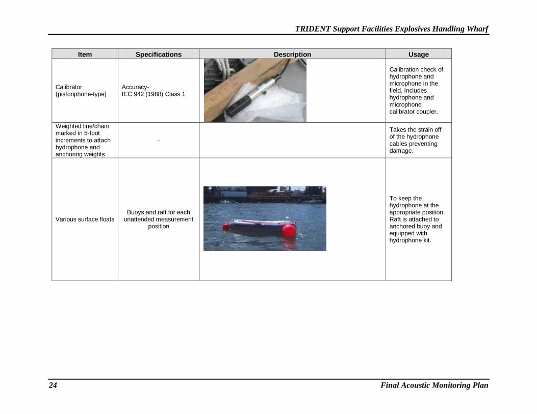
Item Specifications Description Usage
Calibrator (pistonphone-type)
Accuracy- IEC 942 (1988) Class 1
Calibration check of hydrophone and microphone in the field. Includes hydrophone and microphone calibrator coupler.
Weighted line/chain marked in 5-foot increments to attach hydrophone and anchoring weights
-
Takes the strain off of the hydrophone cables preventing damage.
Various surface floats Buoys and raft for each
unattended measurement position
To keep the hydrophone at the appropriate position. Raft is attached to anchored buoy and equipped with hydrophone kit.

TRIDENT Support Facilities Explosives Handling Wharf
Final Acoustic Monitoring Plan 25
Item Specifications Description Usage
2-channel system showing SLMs, Multi-gain amplifiers, 12-volt battery and headphones
Hydrophones used to measure underwater sounds

TRIDENT Support Facilities Explosives Handling Wharf
26 Final Acoustic Monitoring Plan
7.0 SIGNAL PROCESSING
Post-analysis of the recorded time-series signals will include the following: determination of the
mean rise time and duration of recorded strikes, average and maximum absolute value of the
instantaneous pressure for recorded strikes, RMS value for recorded pile strikes, mean and
standard deviation/error of the RMS for recorded pile strikes of each pile, SEL value for
recorded pile strikes, maximum and mean SEL for all strikes in a recorded pile, number of
strikes per pile and per day, calculation of the cumulative SEL (cumulative SEL = single strike
SEL + 10*log [# hammer strikes]) per pile and per day, number of strikes exceeding 206
dBpeak, number, and percent of individual strikes exceeding 183 dB SEL, 187 dB SEL, and 202
dB SEL, and a frequency spectrum between a minimum of 10 and 20,000 Hz for up to eight
successive strikes with similar sound levels. Calculation methodology is provided in Appendix
A. The acoustic contractor should confirm with the Navy prior to post-processing of any data
the methodology for calculating the RMS, SEL, and Leq values.
8.0 ANALYSIS
Analysis of the data from the San Francisco-Oakland Bay Bridge Pile Driving Demonstration
project indicated that 90 percent of the acoustic energy for most pile driving impulses occurred
over a 50- to 100-millisecond period with most of the energy concentrated in the first 30 to 50
milliseconds (Illingworth and Rodkin, Inc. 2001). The RMS values for impulsive strikes will be
computed for this project over the duration between where 5 percent and 95 percent of the
energy of the pulse occurs. The RMS values for continuous sound sources (i.e. vibratory and
ambient) will be calculated for sound levels measured in10-second durations over the duration of
the event; the final RMS value for the event will be the average of all 10-second RMS sound
levels. Cumulative energy levels and SEL will be calculated from the data between 5 and 95
percent of the energy of the individual pulse. The SEL energy plot will assist in interpretation of
the single-strike waveform. The single-strike SEL, along with the total number of strikes per
pile and per day, will be used to calculate the cumulative SEL for each pile and each 24-hour
period. Units of underwater sound pressure levels will be dB re 1 -µPa and units of SEL will be
re 1 µPa2-sec.
9.0 REPORTING
A draft report will be submitted by the Navy to the USFWS and NMFS within 90 calendar days
of the completion of hydroacoustic monitoring. The results will be summarized in graphical
form and include summary statistics and time histories of impact sound values for each pile. A
final report will be prepared and submitted by the Navy to the USFWS and NMFS within 30
calendar days following receipt of comments on the draft report from the regulatory agencies.
The Navy will contact USFWS and NMFS immediately should any unexpected circumstances
occur during construction which require the consultation of the regulatory agencies for guidance.
The final report will include the following information for all monitored piles:
Size and type of piles

TRIDENT Support Facilities Explosives Handling Wharf
Final Acoustic Monitoring Plan 27
Detailed description and pictures/schematics of the sound attenuation devices including
the bubble curtains and their design specifications
The impact hammer energy rating used to drive the piles, make and model of the hammer
Description of the sound monitoring equipment
Distance between hydrophones and pile
Depth of the hydrophones and depth of the water at hydrophone locations
Distance from the pile to the water’s edge
Depth of water in which the pile was driven
Depth into the substrate that the pile was driven
Physical characteristics of the bottom substrate into which the piles were driven
The total number of strikes to drive each pile and for all piles driven during a 24-hour
period
Total number of strikes to drive each pile that is monitored
Duration of pile driving (vibratory or impact) during each monitored day
Ambient sound pressure levels in air would be reported unweighted and A-weighted as
an Leq and would be reported underwater in RMS.
Results of the hydroacoustic monitoring, including the frequency spectrum, ranges and
means including standard deviation/error for peak and RMS SPLs, single-strike and
cumulative SEL.
An estimation of the number of strikes that exceeded the cumulative SEL thresholds (183
dB SEL, 202 dB SEL, 208 dB SEL) and an estimation of the distance at which the peak
and cumulative SEL values reach the respective thresholds and the distance at which the
RMS values reach the relevant marine life thresholds and background sound levels
Vibratory monitoring results, which will include the maximum and overall average RMS
calculated for each monitored pile.
Description of any observable marine mammal, fish, or bird behavior in the immediate
area and, if possible, correlation to underwater sound levels occurring at that time.
Comparison of modeled results and field results.
10.0 REFERENCES
Illingworth & Rodkin, Inc. 2001. Final Data Report: Noise and Vibration Measurements
Associated with the Pile Demonstration Project for the San Francisco-Oakland Bay
Bridge East Span. August 2001.
NAVFAC. 2011a. Biological Assessment for the TRIDENT Support Facilities Explosives
Handling Wharf, NBK Bangor. Submitted to National Marine Fisheries Service, National
Oceanic and Atmospheric Administration and U.S. Fish and Wildlife Service. Prepared
TRIDENT Support Facilities Explosives Handling Wharf
28 Final Acoustic Monitoring Plan
by Naval Facilities Engineering Command Northwest, Silverdale, WA. Prepared for
United States Department of the Navy, Strategic Systems Programs, Washington, DC.
NAVFAC. 2011b. Request for Letter of Authorization for the Incidental Harassment of Marine
Mammals Resulting from the TRIDENT Support Facilities Second Explosives Handling
Wharf, Naval Base Kitsap at Bangor. Submitted to Office of Protected Resources,
National Marine Fisheries Service, National Oceanic and Atmospheric Administration.
Prepared by Naval Facilities Engineering Command Northwest, Silverdale, WA.
Prepared for United States Department of the Navy, Strategic Systems Programs,
Washington, DC. December 16, 2011.
WSDOT. 2005. Underwater sound levels associated with restoration of the Friday Harbor Ferry
Terminal. Prepared for Washington Department of Transportation. May 2005.

TRIDENT Support Facilities Explosives Handling Wharf Appendix A
Final Acoustic Monitoring Plan A–1
APPENDIX A
CALCULATION OF CUMULATIVE SEL
An estimation of individual SEL values can be calculated for each pile strike by calculating a
1-second Leq for each individual pile strike. As can be seen in equation 1 below the SEL is
essentially a subset of the Leq function. When the time interval for the Leq is set to 1 second it
is equal to the SEL. The accumulated SEL values produced by calculating a 1-second Leq for
each pile strike can then be accumulated for each pile strike.
= (eq. 1)
Calculating a cumulative SEL from individual SEL values cannot be accomplished simply by
adding each SEL decibel level arithmetically. Because these values are logarithms they must first
be converted to antilogs and then accumulated. This will be done by dividing each SEL decibel
level by 10 and then taking the antilog. This will convert the decibels to units of microPascals.
These values will be pasted into a spreadsheet and then sorted from smallest to largest value. In
a separate column, starting with the second row of these values, each value is added to the one
above it, which is repeated to the last row of data. The last value in this column is the
cumulative SEL in units of microPascals squared second. Next, the microPascal values are
converted to dB SEL by dividing each value by the total number of values and calculating the
log base 10 of each of these values, then multiplying by 20 to get dB SEL.
These values will be plotted on a cumulative plot such as the one below.
dBdtp
tp
TL
T
Teq0 2
0
2
,
)(1lg10 dBdt
p
tpSEL
2
0
2 )(lg10