Embed Size (px)
Citation preview

TRIGARD®
Gas Monitor
Instruction Manual
THIS MANUAL MUST BE CAREFULLY READ BY ALL INDIVIDUALS WHO HAVE OR WILL
HAVE THE RESPONSIBILITY FOR USING OR SERVICING THE PRODUCT. Like any piece
of complex equipment, this instrument will perform as designed only if it is used and
serviced in accordance with the manufacturer’s instructions. OTHERWISE, IT COULD
FAIL TO PERFORM AS DESIGNED AND PERSONS WHO RELY ON THIS PRODUCT FOR
THEIR SAFETY COULD SUSTAIN SEVERE PERSONAL INJURY OR LOSS OF LIFE.
The warranties made by Mine Safety Appliances Company with respect to the product are
voided if the product is not used and serviced in accordance with the instructions in this
manual. Please protect yourself and others by following them. We encourage our cus-
tomers to write or call regarding this equipment prior to use or for any additional infor-
mation relative to use or repairs.
In North America, to contact your nearest stocking location, dial toll-free 1-800-MSA-INST
To contact MSA International, dial (724) 776-8626
© MINE SAFETY APPLIANCES COMPANY 2013 - All Rights Reserved
This manual is available on the internet at www.msasafety.com
Manufactured by
MSA NORTH AMERICA1000 Cranberry Woods Drive, Cranberry Township, Pennsylvania 16066
(L) Rev 3 10072857
"! WARNING

MSA Instrument Warranty1. Warranty- Seller warrants that this product will be free from
mechanical defect or faulty workmanship for a period of eighteen(18) months from date of shipment or one (1) year from installation,whichever occurs first, provided it is maintained and used inaccordance with Seller’s instructions and/or recommendations.This warranty does not apply to expendable or consumable partswhose normal life expectancy is less than one (1) year such as,but not limited to, non-rechargeable batteries, sensor elements,filter, lamps, fuses etc. The Seller shall be released from allobligations under this warranty in the event repairs or modificationsare made by persons other than its own or authorized servicepersonnel or if the warranty claim results from physical abuse ormisuse of the product. No agent, employee or representative of theSeller has any authority to bind the Seller to any affirmation,representation or warranty concerning the goods sold under thiscontract. Seller makes no warranty concerning components oraccessories not manufactured by the Seller, but will pass on to thePurchaser all warranties of manufacturers of such components.THIS WARRANTY IS IN LIEU OF ALL OTHER
WARRANTIES, EXPRESSED, IMPLIED OR STATUTORY, AND ISSTRICTLY LIMITED TO THE TERMS HEREOF. SELLERSPECIFICALLY DISCLAIMS ANY WARRANTY OFMERCHANTABILITY OR OF FITNESS FOR A PARTICULARPURPOSE.
2. Exclusive Remedy- It is expressly agreed that Purchaser’s soleand exclusive remedy for breach of the above warranty, for anytortious conduct of Seller, or for any other cause of action, shall bethe repair and/or replacement at Seller’s option, of any equipmentor parts thereof, which after examination by Seller is proven to bedefective. Replacement equipment and/or parts will be provided atno cost to Purchaser, F.O.B. Seller’s Plant. Failure of Seller tosuccessfully repair any nonconforming product shall not cause theremedy established hereby to fail of its essential purpose.
3. Exclusion of Consequential Damage- Purchaser specificallyunderstands and agrees that under no circumstances will seller beliable to purchaser for economic, special, incidental orconsequential damages or losses of any kind whatsoever, includingbut not limited to, loss of anticipated profits and any other losscaused by reason of nonoperation of the goods. This exclusion isapplicable to claims for breach of warranty, tortious conduct or anyother cause of action against seller.
General Warnings and Cautions
1. The Trigard Gas Monitors described in this manual must beinstalled, operated and maintained in strict accordance with theirlabels, cautions, warnings, instructions, and within the limitationsstated.
2. The Trigard Gas Monitor is designed to detect gases or vapors inair. It cannot measure the concentration of gases or vapors insteam or inert or oxygen-deficient atmospheres. The oxygensensor can measure oxygen-deficient atmospheres.
3. Electrochemical sensors are sealed units which contain a corrosiveelectrolyte. Should a sensor develop leakage, it must beimmediately removed from service; then, remove it from thesensing head and discard it properly. Caution must be exercised sothat the electrolyte does not contact skin, eyes, clothing or circuitry;otherwise, serious personal injury (burns) and/or equipmentdamage may result.
4. Use only genuine MSA replacement parts when performing anymaintenance procedures provided in this manual. Failure to do somay seriously impair instrument performance. Repair or alterationof the Trigard Gas Monitor, beyond the scope of thesemaintenance instructions or by anyone other than an authorizedMSA service personnel, could cause the product to fail to performas designed and persons who rely on this product for their safetycould sustain serious personal injury or death.
5. Do not locate the general-purpose enclosure models in an areawhich may contain a flammable mixture of gas and air; otherwise,an explosion may occur. The general-purpose Trigard GasMonitors can be a source of ignition and must not be mounted inan area where a flammable mixture of combustible gas and airmay become present; otherwise, an explosion may occur.
Failure to follow the above can result in serious personalinjury or death.
" WARNING
i

1. As with all gas monitors of these types, high levels of, or longexposure to, certain compounds in the tested atmosphere couldcontaminate the sensors. In atmospheres where Trigard GasMonitor may be exposed to such materials, calibration must beperformed frequently to ensure that operation is dependable anddisplay indications are accurate.
2. The Trigard Gas Monitor must not be painted. If painting is done inan area where a Monitor is located, care must be exercised toensure that paint is not deposited on the sintered, metal flashbackarrestor in the inlet fitting of the Trigard Gas Monitor, if soequipped. Such paint deposits would interfere with the diffusionprocess, whereby a sample of the atmosphere being monitoreddiffuses into the Monitor.
3. The only absolute method to ensure proper overall operation ofTrigard Monitor is to check it with a known concentration of the gasfor which it has been calibrated. Consequently, calibration checksmust be included as part of the routine inspection of the system.
4. Protect the Trigard Gas Monitor from extreme vibration. Do notmount the sensing head in direct sunlight as this may causeoverheating of the sensor.
Failure to follow the above can result in injury, productdamage and/or an unsafe condition.
" CAUTION
ii
Table of Contents
Chapter 1, Installation . . . . . . . . . . . . . . . . . . . . . . . . . . . . . .1-1
General Description . . . . . . . . . . . . . . . . . . . . . . . . . . . . . . . . .1-1
Identifying Your Unit . . . . . . . . . . . . . . . . . . . . . . . . . . . . . . . .1-1
Installing Your Gas Monitor . . . . . . . . . . . . . . . . . . . . . . . . . . .1-2
Installing the Trigard Gas Monitor . . . . . . . . . . . . . . . .1-3
Electrical Connections for Trigard Gas Monitors . . . . . . . . . . .1-3
Wiring . . . . . . . . . . . . . . . . . . . . . . . . . . . . . . . . . . . . . .1-3
For Milliamp Output . . . . . . . . . . . . . . . . . . . . . . . . . . .1-4
Typical Trigard Gas Monitor Wiring . . . . . . . . . . . . . . . . . . . . .1-5
Installing the Trigard Remote Sensor Module . . . . . . . . . . . . .1-7
Electrical Connections for the Trigard
Remote Sensor Module . . . . . . . . . . . . . . . . . . . .1-9
At the Trigard Remote Sensor Location: . . . . . . . . . .1-10
Chapter 2, Start-up and Calibration for 4-20 mA Output . .2-1
Initial Start-up . . . . . . . . . . . . . . . . . . . . . . . . . . . . . . . . . . . . . .2-1
Calibration Basics . . . . . . . . . . . . . . . . . . . . . . . . . . . . . . . . . .2-3
Chemicals that Reduce Catalytic Sensor Sensitivity . .2-4
Ultima Calibrator . . . . . . . . . . . . . . . . . . . . . . . . . . . . .2-5
Ultima Controller . . . . . . . . . . . . . . . . . . . . . . . . . . . . .2-5
Note on Resetting Latched Alarms
with Controller or Calibrator . . . . . . . . . . . . . . . . . . . . .2-6
Trigard Gas Monitor Calibration Output Signal . . . . . .2-6
Calibration Kit . . . . . . . . . . . . . . . . . . . . . . . . . . . . . . .2-6
Trigard Gas Monitor Calibration Procedure . . . . . . . . . . . . . . .2-7
INITIAL Calibration . . . . . . . . . . . . . . . . . . . . . . . . . . . .2-7
Regular Calibration . . . . . . . . . . . . . . . . . . . . . . . . . . .2-8
Zeroing . . . . . . . . . . . . . . . . . . . . . . . . . . . . . . . . . . . . .2-8
Spanning . . . . . . . . . . . . . . . . . . . . . . . . . . . . . . . . . .2-10
Calibration Documentation . . . . . . . . . . . . . . . . . . . .2-12
iii

Chapter 3, Start-up and Calibration for MODBUS output . .3-1
Typical ModBUS Network Topography (FIGURE 3-1). . . . . . .3-1
Sensors . . . . . . . . . . . . . . . . . . . . . . . . . . . . . . . . . . . .3-1
Wiring . . . . . . . . . . . . . . . . . . . . . . . . . . . . . . . . . . . . . .3-1
Power . . . . . . . . . . . . . . . . . . . . . . . . . . . . . . . . . . . . . .3-1
RS485 Communications . . . . . . . . . . . . . . . . . . . . . . .3-1
Transmitter Sensor Distance . . . . . . . . . . . . . . . . . . .3-1
Typical Communication Cable Wiring . . . . . . . . . . . . . . . . . .3-5
Operation . . . . . . . . . . . . . . . . . . . . . . . . . . . . . . . . . . .3-5
Alarm Status Screen . . . . . . . . . . . . . . . . . . . . . . . . . .3-7
Ultima Controller or Ultima Calibrator: . . . . . . . . . . . . .3-8
Calibration . . . . . . . . . . . . . . . . . . . . . . . . . . . . . . . . . .3-9
ModBUS Communications . . . . . . . . . . . . . . . . . . . . .3-10
ModBUS Addressing . . . . . . . . . . . . . . . . . . . . . . . . .3-10
ModBUS Communications . . . . . . . . . . . . . . . . . . . . .3-11
ModBUS Base Address (Read/Write) . . . . . . . . . . . .3-12
Chapter 4, Additional Features . . . . . . . . . . . . . . . . . . . . . . .4-1
Internal Relays . . . . . . . . . . . . . . . . . . . . . . . . . . . . . . . . . . . .4-1
General Information . . . . . . . . . . . . . . . . . . . . . . . . . . .4-1
Installing the Trigard Gas Monitor
with Internal Relays . . . . . . . . . . . . . . . . . . . . . . . . . . .4-1
Trigard Gas Monitor Internal Relays . . . . . . . . . . . . . .4-2
Relay Specifications . . . . . . . . . . . . . . . . . . . . . . . . . . .4-2
Alarm Relays . . . . . . . . . . . . . . . . . . . . . . . . . . . . . . . .4-2
Fault Relay or Trouble . . . . . . . . . . . . . . . . . . . . . . . . .4-3
Calibration/RESET Push-button . . . . . . . . . . . . . . . . . . . . . . .4-4
Push-button Calibration . . . . . . . . . . . . . . . . . . . . . . . . . . . . . .4-5
Relay Connections . . . . . . . . . . . . . . . . . . . . . . . . . . . .4-6
Horn Relay Software . . . . . . . . . . . . . . . . . . . . . . . . . . . . . . . .4-7
To Activate the Horn Relay . . . . . . . . . . . . . . . . . . . . .4-7
To Reset the Horn Relay . . . . . . . . . . . . . . . . . . . . . . .4-7
Chapter 5, Specifications . . . . . . . . . . . . . . . . . . . . . . . . . . . .5-1
iv
Chapter 6, Maintenance . . . . . . . . . . . . . . . . . . . . . . . . . . . . .6-1
General . . . . . . . . . . . . . . . . . . . . . . . . . . . . . . . . . . . . . . .6-1
Replacing Trigard Sensor . . . . . . . . . . . . . . . . . . . . . .6-1
Obtaining Replacement Parts . . . . . . . . . . . . . . . . . . . . . . . . .6-6
Appendix A, Optional Features . . . . . . . . . . . . . . . . . . . . . . . .A-1
Strobes . . . . . . . . . . . . . . . . . . . . . . . . . . . . . . . . . . . . . . .A-1
Internal Power Supply . . . . . . . . . . . . . . . . . . . . . . . . . . . . . . .A-2
Backup Battery . . . . . . . . . . . . . . . . . . . . . . . . . . . . . . . . . . . .A-2
List of Figures
Figure 1-1. Trigard Gas Monitor . . . . . . . . . . . . . . . . . . . . . . .1-1
Figure 1-2. Circuit Board (3-Wire Version) . . . . . . . . . . . . . . .1-6
Figure 1-3. Three-Wire 4 to 20 mA Operation . . . . . . . . . . . . .1-7
Figure 1-4. Remote Sensor Cable Assemblies . . . . . . . . . . . .1-7
Figure 1-5. General-Purpose Remote Sensor Assemblies . . .1-8
Figure 1-6. Explosion-Proof Remote Sensor Assemblies . . . .1-8
Figure 2-1. LCD Gas Concentration Display . . . . . . . . . . . . . .2-1
Figure 2-3. Ultima Controller . . . . . . . . . . . . . . . . . . . . . . . . . .2-5
Figure 2-2. Ultima Calibrator . . . . . . . . . . . . . . . . . . . . . . . . . .2-5
Figure 2-4. Apply Zero Gas Flag . . . . . . . . . . . . . . . . . . . . . . .2-9
Figure 2-5. Apply SPAN Gas Flag . . . . . . . . . . . . . . . . . . . . .2-10
Figure 2-6. Calibration End Display . . . . . . . . . . . . . . . . . . . .2-11
Figure 3-1. Typical ModBUS Network Topography . . . . . . . . .3-2
Figure 3-2. Typical Communications Wiring Scheme . . . . . . .3-4
Figure 3-3. Sensor Display Screens . . . . . . . . . . . . . . . . . . . .3-6
Figure 3-4. Alarm Status Screen . . . . . . . . . . . . . . . . . . . . . . .3-8
Figure 3-5. ModBus PCB . . . . . . . . . . . . . . . . . . . . . . . . . . . .3-9
FIGURE 4-1. Relay Contacts . . . . . . . . . . . . . . . . . . . . . . . . .4-4
Figure 6-1. "Change Sensor" Scrolls Across the Display . . . .6-1
Figure 6-2. Sensor Assembly and Sensor Guard for General
Purpose Model . . . . . . . . . . . . . . . . . . . . . . . . . . .6-2
Figure A-1. Trigard Gas Monitor with Additional Options . . . .A-1
Figure A-2. Trigard Gas Monitor Power Supply and Battery
Backup Options . . . . . . . . . . . . . . . . . . . . . . . . . .A-2
v

List of Tables
Table 1-1. Power Cable Distances for the Trigard Gas
Monitor with Internal Relays (4-20 mA Model) . . .1-5
Table 1-2. Cable Length and Wire Size
(Power Supply 24 VDC) (Toxic Gas or Oxygen)
Sensor, 4-20 mA Signal Output
(Three Wire Sensor) . . . . . . . . . . . . . . . . . . . . . .1-5
Table 1-3. Remote Module Wiring and Placement . . . . . . . . .1-9
Table 1-4. Remote Sensor Wiring Cable . . . . . . . . . . . . . . . .1-10
Table 1-5. Low Temperature Wiring Cable . . . . . . . . . . . . . .1-10
Table 2-1. Instrument Operation . . . . . . . . . . . . . . . . . . . . . . .2-2
Table 3-1. Maximum Power Cable Length . . . . . . . . . . . . . . .3-3
Table 3-2. Transmitter Power Consumption
(7-30 VDC Supply) . . . . . . . . . . . . . . . . . . . . . . . .3-3
Table 3-3. Remote Sensor Power Consumption
(AC or DC Operation) . . . . . . . . . . . . . . . . . . . . .3-3
Table 3-4. Status Indication Codes . . . . . . . . . . . . . . . . . . . . .3-8
Table 3-5. Supported ModBUS Function Codes . . . . . . . . . .3-11
Table 3-6. ModBUS Memory Map Overview . . . . . . . . . . . . .3-11
Table 3-7. ModBUS Bas Address (Read/Write) . . . . . . . . . .3-12
Table 3-8. ModBUS Factory Configuration Data
(Read Only) . . . . . . . . . . . . . . . . . . . . . . . . . . . .3-13
Table 3-9. ModBUS User Configuration Data (Read/Write) .3-14
Table 3-10. Alarm Function Codes - Word 1(Read/Write at
Address Base+137) . . . . . . . . . . . . . . . . . . . . . .3-15
Table 3-11. Alarm Function Codes - Word 2(Read/Write at
Address Base+138) . . . . . . . . . . . . . . . . . . . . . .3-16
Table 3-12. ModBUS Device Status (Read only) . . . . . . . . .3-17
Table 3-13. ModBUS General Status Bits
(Read Only at address Base+201) . . . . . . . . . .3-19
Table 3-14. ModBUS Fault Status Bits
(Read Only at address Base+202) . . . . . . . . . .3-19
Table 3-15. Control Words (Read/Write) . . . . . . . . . . . . . . . .3-20
Table 3-16. ModBUS Command Word 1 (Read at address
Base+301/Write Coils 1 through 16) . . . . . . . . .3-20
Table 13-17 ModBUS Command Word 2 (Read at address
Base+302/Write Coils 17 through 32) . . . . . . . .3-21
Table 3-18. Sensor Type . . . . . . . . . . . . . . . . . . . . . . . . . . . .3-22
Table 3-19. Sensor Engineering Units . . . . . . . . . . . . . . . . . .3-23
vi
Table 3-20. Information Flags Word #1 –
(Read at address Base+254) . . . . . . . . . . . . . . .3-23
Table 3-21. Information Flags Word #2
(Read at address Base+255) . . . . . . . . . . . . . . .3-24
Table 3-22. Information Flags Word #3
(Read at address Base+26) . . . . . . . . . . . . . . . .3-24
Table 3-23. Information Flags Word #4
(Read at address Base+257) . . . . . . . . . . . . . . .3-25
Table 3-24. Alternate Gas Readings (Read/Write
at address Base+258 to Base+260) . . . . . . . . .3-25
Table 4-1. Relay Specifications . . . . . . . . . . . . . . . . . . . . . . . .4-2
Table 4-2. Push-button Calibration . . . . . . . . . . . . . . . . . . . . .4-5
Table 5-1. Performance Specifications . . . . . . . . . . . . . . . . . .5-1
Table 5-2. Sensor Response to Interferants . . . . . . . . . . . . . .5-4
Table 6-1. Operational Display Messages . . . . . . . . . . . . . . . .6-3
Table 6-2. Configuration Display Messages . . . . . . . . . . . . . .6-4
Table 6-3. Troubleshooting Guidelines . . . . . . . . . . . . . . . . . .6-5
Table 6-4. Replacement Parts . . . . . . . . . . . . . . . . . . . . . . . . .6-6
vii

Chapter 1, Installation
General Description
The Trigard Gas Monitor is designed to sample the environment wheremounted and alert you to potentially dangerous levels of your targetgas, depending on your particular model. The unit is factory-calibratedand shipped ready for installation.
Identifying Your Unit
• The Trigard Gas Monitor is housed in a rugged, plastic general-purpose enclosure (FIGURE 1-1).
• The Trigard Gas Monitor comes standard with internal relays, aCal/Reset pushbutton, and a 95 dB horn. See Chapter 4 for details.
• The gas sensor type and range are located on the sensor modulelabel. Unscrew the sensor assembly to view the label.
Any options ordered, such as Strobes, Battery Backup or Internal AC Power Supply, will be included.
Figure 1-1. TRIGARD Gas Monitor
1-1

Installing Your Gas Monitor
NOTE: Reference installation outline drawings listed in Chapter 3,"Specifications".
Generally, the Trigard Gas Monitors or remote sensing module shouldbe mounted close to the area where a leak is likely to occur or wherethe gas is expected. Install the Trigard Gas Monitors or the remotesensor at a high level (ceiling) or low level (floor), depending on thedensity of the gas most likely to be found. Install the unit so that thefront display is not blocked or hidden from view.
Mount the Trigard Gas Monitor or remote sensor with thesensor inlet fitting (FIGURE 1-1) pointed downward; other-wise, the inlet may become clogged with particulate matteror liquids.
Do not paint the Trigard Gas Monitors. If painting is done inan area where a sensor is located, exercise CAUTION toensure paint is not deposited on the sensor inlet fitting.Such paint deposits would interfere with the diffusionprocess, whereby a sample of the monitored atmospherediffuses into the sensor. In addition, solvents in the paintmay cause an alarm condition to occur.
Protect the Trigard Gas Monitors from extreme vibration. Donot mount sensing head in direct sunlight as this may causeoverheating of the sensor.
Do not locate the general-purpose enclosure models in anarea which may contain a flammable mixture of gas and air;otherwise, an explosion may occur. The general-purposeTrigard Gas Monitors can be a source of ignition and mustnot be mounted in an area where a flammable mixture ofcombustible gas and air may become present.
" WARNING
" WARNING
1-2

Installing the Trigard Gas Monitor
Remove lid and drill enclosure for power, signal and optional relay cableentry. Use one of the following methods to mount the general-purposeTrigard Gas Monitor.
• Using customer-installed wiring holes, install the Trigard GasMonitor to the end of rigid conduit.
• Use mounting holes in the corners of the Trigard enclosure tomount directly to a wall.
Electrical Connections for Trigard Gas Monitors
Before wiring the Trigard Gas Monitors, disconnect powersource supplying the monitor; otherwise, electrical shockcould occur.
NOTE: For information on internal relays, see Chapter 4.For Trigard units with ModBUS, see Chapter 3.
This three-wire assembly is marked to identify power, ground and signalconnections for all combustible, toxic, and oxygen models.
Wiring
Install wiring in accordance with the electrical code of the country in useand UL 61010-A1 or CSA C22.2 No. 1010.1, as applicable. In theseinstallations, twisted-pair, instrument quality cable is recommended.Shielded cable is recommended for cable runs where interferences fromradio frequency interference (RFI), electromagnetic interference (EMI)or other noise sources exist (such as motors, welding equipment,heaters, etc.).
NOTE: See Installation Outline Drawings for wiring details.
Conduit may also be needed in areas where large amounts of electricalnoise is expected.
Use caution when selecting a cable size. TABLES 1-1 and 1-2 expressthe maximum cable length when only using the Trigard Gas Monitors.Trigard options may take additional power which requires a heaviercable or a short cable run.
" WARNING
1-3

When selecting cable size, consider future needs (i.e., addition ofsensors and/or options available with the Trigard Monitors). SeeChapter 3, "Specifications" for proper input voltage.
Ensure that water and dirt are not able to enter the unit via the wire orconduit. If the unit is installed in a location known to be wet or damp, itis good practice to loop or bend the entry into the unit that preventswater incursion.
For Milliamp Output
The Trigard Gas Monitor (three-wire version) may be connected to anydevice capable of accepting 4 to 20 mA analog signals such as:
• Model 9010/9020 Controller
• GasGard XL Controller
• Programmable controllers
• DCS’s, etc.
An external power supply is needed if the optional internal power supplyis not ordered. (For power requirements, see Chapter 3,"Specifications".) All connections should be made by followingappropriate wire code procedures.
• See TABLES 1-1 through 1-2 for typical cable length and wire sizefor installation.
When using any of the the Trigard accessories (such asrelays) with the 4 to 20 mA output Trigard Gas Monitor, athree-wire connection must be used. Failure to use a three-wire connection could damage the electronics within theTrigard Gas Monitor which can result in serious personalinjury or death.
Be sure to install your Trigard Gas Monitor according to NationalElectrical and local procedural codes. Failure to do so can result in anunsafe condition.
NOTE: See Chapter 3 for ModBUS output.
" WARNING
1-4

Table 1-1. Power Cable Distances for the Trigard Gas Monitor with InternalRelays (4-20 mA Model)
SENSOR TYPE POWER WIRE SIZE MAXIMUM MAXIMUM LOADSUPPLY CABLE RESISTANCEVOLTAGE LENGTH (mA OUTPUT
(IN FEET) ONLY)
CATALYTIC
COMBUSTIBLE 12 VDC 16 AWG 900 300 OHMS
CATALYTIC
COMBUSTIBLE 24 VDC 16 AWG 3000 600 OHMS
TOXIC OR OXYGEN 12 VDC 16 AWG 2500 300 OHMS
TOXIC OR OXYGEN 24 VDC 16 AWG 8000 600 OHMS
• See TABLE 1-6 for remote sensor distances.
• In all installations, twisted instrument-quality cable isrecommended.
• Shielded cable is recommended in situations where radiofrequency interference (RFI), electro-magnetic interference (EMI)or other electrical noise sources exist or are anticipated.
Typical Trigard Gas Monitor Wiring
Table 1-2. Cable Length and Wire Size (Power Supply 24 VDC) (Toxic Gas or Oxygen) Sensor, 4-20 mA Signal Output (Three Wire Sensor)
WIRE SIZE MAXIMUM CABLE LENGTH IN FEET MAXIMUM LOAD RESISTANCE
22 AWG 12,000 600 Ohms
• Three-wire Trigard Monitors operate in the current source mode(see FIGURE 1-3).
1. Identify the main pc board:
• It is the round pc board, located inside the lid assembly.
1-5
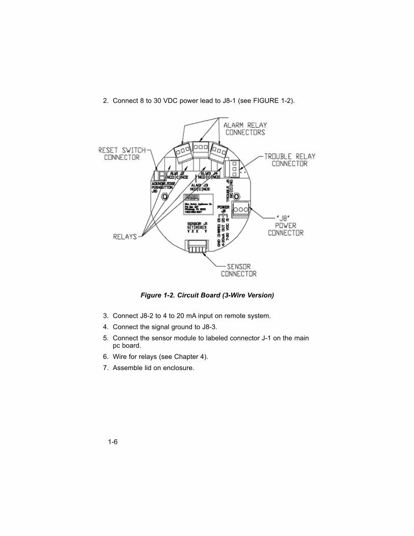
2. Connect 8 to 30 VDC power lead to J8-1 (see FIGURE 1-2).
3. Connect J8-2 to 4 to 20 mA input on remote system.
4. Connect the signal ground to J8-3.
5. Connect the sensor module to labeled connector J-1 on the mainpc board.
6. Wire for relays (see Chapter 4).
7. Assemble lid on enclosure.
Figure 1-2. Circuit Board (3-Wire Version)
1-6
Installing the Trigard Remote Sensor Module
The Remote Sensor Modules are available in a variety of options.
Pre-wired general-purpose sensors are available in lengths of 25, 50 or100 feet. These remote sensors are not housed in an enclosure, whichmakes it easier to mount in small places.
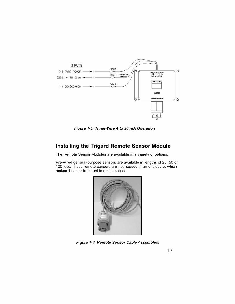
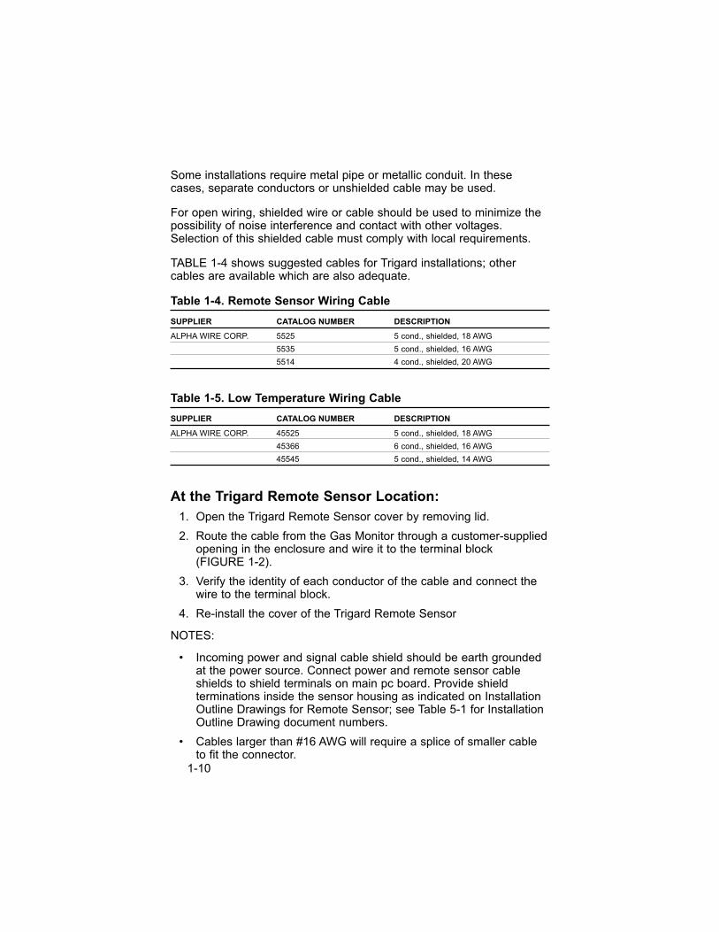
Figure 1-4. Remote Sensor Cable Assemblies
Figure 1-3. Three-Wire 4 to 20 mA Operation
1-7

Remote sensors can be ordered with general purpose (GP) remotesensor assemblies.
Remote sensors can also be ordered with explosion-proof (XP) remotesensor assemblies.
Figure 1-6. Explosion-Proof Remote Sensor Assemblies
Figure 1-5. General-Purpose Remote Sensor Assemblies
1-8

The GP or XP Remote Sensor Modules can be mounted in a mannersimilar to the gas monitor installation in the preceding procedure and ata maximum distance outlined in TABLE 1-3.
Table 1-3. Remote Module Wiring and Placement
GAS TYPE MINIMUM WIRE SIZE MAXIMUM DISTANCE
Toxic and Oxygen 20 AWG 100 FEET
Catalytic Combustible 18 AWG 50 FEET
16 AWG 100 FEET
IR Combustible 16 AWG 50 FEET
12 AWG 100 FEET
Permanently connect 1/4" ID tubing to the post on the windguard. Routethis tubing to the Trigard Gas Monitor, ensuring that there are no kinks,leaks or other obstructions. Secure this tubing near the monitor; it isused to deliver check gas to the sensor module during calibration.
Tubing used for reactive gases (Cl2, HCl, ClO2, HF, NH3,ETO, F2, B2H6, Br) should be as short as possible (18 inch-es maximum) to ensure that the gas reaches the sensor.Excessive tubing can result in no gas sensor reading.
Electrical Connections for the Trigard RemoteSensor Module
Before wiring the Trigard Remote Sensor Module, discon-nect the power source feeding the Remote Sensor Moduleand the Trigard Gas Monitor/Less Sensor; otherwise, electri-cal shock could occur.
When installing Trigard Remote Sensor Module with its mat-ing Trigard Gas Monitor/Less Sensor, follow NationalElectrical and local procedural Codes; failure to do so canresult in an unsafe condition.
Five conductors are required for the Trigard Remote Sensor Module.The Trigard Monitor has a five-wire terminal to accommodate up to #16AWG conductors.
" CAUTION
" WARNING
" CAUTION
1-9
Some installations require metal pipe or metallic conduit. In thesecases, separate conductors or unshielded cable may be used.
For open wiring, shielded wire or cable should be used to minimize thepossibility of noise interference and contact with other voltages.Selection of this shielded cable must comply with local requirements.
TABLE 1-4 shows suggested cables for Trigard installations; othercables are available which are also adequate.
Table 1-4. Remote Sensor Wiring Cable
SUPPLIER CATALOG NUMBER DESCRIPTION
ALPHA WIRE CORP. 5525 5 cond., shielded, 18 AWG
5535 5 cond., shielded, 16 AWG
5514 4 cond., shielded, 20 AWG
Table 1-5. Low Temperature Wiring Cable
SUPPLIER CATALOG NUMBER DESCRIPTION
ALPHA WIRE CORP. 45525 5 cond., shielded, 18 AWG
45366 6 cond., shielded, 16 AWG
45545 5 cond., shielded, 14 AWG
At the Trigard Remote Sensor Location:
1. Open the Trigard Remote Sensor cover by removing lid.
2. Route the cable from the Gas Monitor through a customer-suppliedopening in the enclosure and wire it to the terminal block (FIGURE 1-2).
3. Verify the identity of each conductor of the cable and connect thewire to the terminal block.
4. Re-install the cover of the Trigard Remote Sensor
NOTES:
• Incoming power and signal cable shield should be earth groundedat the power source. Connect power and remote sensor cableshields to shield terminals on main pc board. Provide shieldterminations inside the sensor housing as indicated on InstallationOutline Drawings for Remote Sensor; see Table 5-1 for InstallationOutline Drawing document numbers.
• Cables larger than #16 AWG will require a splice of smaller cableto fit the connector.
1-10

Chapter 2, Start-up and Calibration for 4-20 mA Output
Initial Start-up
• The Trigard Gas Monitors are factory-calibrated. A bump checkprior to use is recommended.
• Once power is applied to the unit, the LCD shows a test of alldisplay words. The software version number displays; then, a 30-second (self-check) countdown for sensor stability begins.
• During the 30-second countdown, the output signal is the same asthe calibration signal when enabled during a normal calibration.This is described later in this chapter under "Trigard Gas MonitorCalibration Output Signal".
• The Alert red LED will be solid ON during the 30-secondcountdown.
• After the 30-second countdown, observe that the gas type and gas concentration (ppm, % Gas, or % LEL) alternately flash(FIGURE 2-1).
1).
• The Normal green LED will be solid ON after the 30-secondcountdown.
• A complete listing of instrument operation features can be found inTABLE 2-1.
Figure 2-1. LCD Gas Concentration Display
2-1
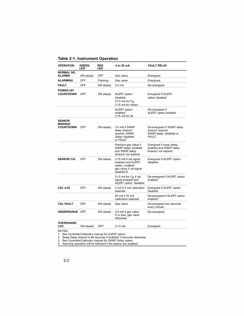
Table 2-1. Instrument Operation
OPERATION GREEN RED 4 to 20 mA FAULT RELAYLED LED
NORMAL NO.ALARMS ON steady OFF Gas value Energized
ALARMING OFF Flashing Gas value Energized
FAULT OFF ON steady 3.0 mA De-energized
POWER UP/
COUNTDOWN OFF ON steady ALERT option1 Energized if ALERT
disabled: option disabled
21.0 mA for O2;
3.75 mA for others
ALERT option1 De-energized ifenabled: ALERT option enabled1
3.75 mA for all
SENSORMISSING/COUNTDOWN OFF ON steady 3.0 mA if SWAP De-energized if SWAP delay
delay timeout2 timeout2 expired,expired, SWAP SWAP delay3 disabled or Delay3 disabled FAULTor FAULT
Previous gas value if Energized if swap delay3
SWAP delay3 enabled enabled and SWAP delayand SWAP delay timeout2 not expiredtimeout2 not expired
SENSOR CAL OFF ON steady 3.75 mA if cal signal Energized if ALERT optionenabled and ALERT disabledoption1 enabled; gas value if cal signal disabled E
21.0 mA for O2 if cal De-energized if ALERT optionsignal enabled and enabled1
ALERT option1 disabled
CAL 4-20 OFF ON steady 4 mA if 4 mA calibration Energized if ALERT option selected disabled
20 mA if 20 mA De-energized if ALERT optioncalibration selected enabled1
CAL FAULT OFF ON steady Gas value De-energized two seconds every minute
UNDERRANGE OFF ON steady 3.0 mA if gas value De-energized0 or less; gas valueotherwise
OVERRANGE/LOC ON steady4 OFF4 21.0 mA Energized
NOTES:1. See Controller/Calibrator manual for ALERT option.2. Swap Delay timeout is 60 seconds if enabled; 0 seconds otherwise.3. See Controller/Calibrator manual for SWAP Delay option.4. Alarming operation will be followed if the alarms are enabled.
2-2
During normal operation, the Trigard Monitor displays the gasconcentration of the surrounding environment. The correspondingoutput signal can be transmitted to a controller.
NOTE: The catalytic combustible model of the Trigard Gas Monitors iscapable of detecting concentrations of certain combustiblegases above 100% LEL. When exposed to these concentra-tions, the Trigard Gas Monitors will display one of two modes:
• +LOC % LEL - The Trigard Gas Monitor has been exposed to ahigh concentration of gas (above the LEL) and there is apossibility that the over-range condition may still exist.
• OVER % LEL - The Trigard Gas Monitor has been exposed to ahigh concentration of gas (above the LEL) and the over-rangecondition definitely still exists.
In either mode, correct the condition causing the excessivegas level and vent or purge the area before attempting thefollowing.
• In the +LOC % LEL mode, the output signal will also be lockedat full-scale. If this condition occurs, the Trigard Gas Monitormust be unlocked by performing a "Zero Function" with theTrigard Gas Monitor Calibrator or Controller. The Trigard GasMonitor will not revert to a normal condition until a successfulzero operation has been performed. This is an exclusive safetyfeature of the Trigard Gas Monitor which pre-empts thepossibility of ambiguous readings when the sensor is exposedto concentration of gas above 100% LEL
• In the OVER % LEL mode, the combustible gas is over the100% LEL range. It returns to normal operation when gasconcentration level falls below 100% LEL.
Calibration Basics
While the Trigard Gas Monitor is factory-calibrated, it is good practice tocalibrate the unit once it is installed in its final environmental destination.
As with any type of gas monitor, the only true check of its performanceis to apply gas directly to the sensor. The frequency of the calibrationgas tests depends on the operating time and chemical exposures of thesensors. New sensors should be calibrated more often until thecalibration records prove sensor stability. The calibration frequency can
" CAUTION
2-3

then be reduced to the schedule set by the safety officer or plantmanager.
Before calibrating, the Trigard Gas Monitor must be powered for aminimum of one hour to allow the sensor to settle into its newenvironment.
Before attempting a calibration, power the unit at least onefull hour.
To ensure a fully functional sensor, perform a calibrationcheck and adjustments at initial start-up and at regular inter-vals.
Chemicals that Reduce Catalytic Sensor Sensitivity
Catalytic Combustible sensors located in areas where non-combustiblechemicals may leak, particularly ones known to reduce the sensitivity(see following list) should be calibrated after such exposures.
• Silanes, Silicates, Silicones and Halides (compounds containingFluorine, Chlorine, Iodine or Bromine)
• TABLE 5-2 in Chapter 5 lists interferants for electrochemicalsensors.
When it is determined that calibration adjustments are required, theTrigard Gas Monitor provides a one-man, non-intrusive method ofadjustment at the unit.
To calibrate the unit, one of the following accessories is necessary:
• Ultima Calibrator P/N 809997 (FIGURE 2-2)
• Ultima Controller P/N 809086 (FIGURE 2-3)
• Push-button Calibration (Chapter 4).
" CAUTION
" CAUTION
2-4

1).
1).
Ultima Calibrator
The Ultima Calibrator allows the following functions:
• Zero
• Calibration (zero and span)
• Changing address for some models.
Ultima Controller
The Ultima Controller also provides the above functions, plus access tothe following features:
• Three levels of alarm and relays
• Date of last successful calibration
Figure 2-2. Ultima Calibrator
Figure 2-3. Ultima Controller
2-5

• Maximum gas readings over selected time periods
• Average gas readings over selected time periods
• Changing span gas value from factory-set value
• Access to real-time clock for time and date
• Changing of full scale value.
NOTE: See Ultima Controller/Calibrator manual (P/N 813379) forfull functionality.
Note on Resetting Latched Alarms with Controller or Calibrator
When Trigard Gas Monitor has an active latched alarm (indicated by aflashing alarm display):
• An infrared (IR) remote device (such as the Ultima Calibrator orController) may be used to reset this alarm.
• The next IR command it receives from a calibration device willreset the latched alarm (if it is not beyond the alarm threshold).The intended IR command will be ignored and interpreted as an’alarm reset.’ When the latching alarm function is inactive, othervalid IR commands may be used.
Trigard Gas Monitor Calibration Output Signal
The Trigard Gas Monitor is shipped with the calibration output signaldisabled so the output signal will track the gas concentration valueduring the calibration process. In some applications, it may be desirableto disable or lock the output to a pre-determined output value to preventactivation of alarm devices. The calibration signal can be enabled usingthe Ultima Controller. When the calibration signal is enabled, the outputsignal is 3.75 milliamps for the 4 to 20 milliamp output models.
NOTE: For the range of 25% oxygen, the calibration signal will be 21mA. Oxygen can be set to a 3.75 mA calibration signal [seeUltima Controller/Calibrator manual (P/N 813379)].
Calibration Kit
Calibration Kits are available for the Trigard Gas Monitors. For therecommended calibration kit, see Ultima Controller/Calibrator manual(P/N 813379).
2-6

Trigard Gas Monitor Calibration Procedure
Read all calibration instructions before attempting an actual calibration.Also, identify and become familiar with all of the calibration components.During the calibration, it is necessary to quickly apply the span gas tothe unit. Prior connection of the calibration components will aid in theease of unit calibration.
The only true check of any gas monitor’s performance is to apply gasdirectly to the sensor. The calibration procedure must be performedregularly.
INITIAL Calibration
When the unit is powered up for the first time, or when a new sensormodule is placed in the unit, an INITIAL Calibration is recommended.This procedure enables the unit to gather data about the sensor tomake accurate decisions for the CHANGE SENSOR function and theCAL FAULT function to work properly. During normal use, INITIALcalibration should only be used when a regular calibration will not cleara fault condition due to use of incorrect calibration gas or anothersimilar situation.
The INITIAL calibration is accomplished by:
• simultaneously pressing the ZERO and CALIBRATE buttons of theUltima Calibrator or
• pressing and holding SPAN button on the Ultima Controller or
• using the optional push-button calibration as outlined in Chapter 4,"Optional Push-button Calibration".
• The display should show "APPLY ZERO GAS"
• The word "ICAL" on the display distinguishes an INITIALCalibration from a regular calibration. If "ICAL" does not appear,abort the calibration; then, retry the above procedure.
NOTE: The zero or calibration process can be aborted at any time sim-ply by pressing any button during the 30-second countdown onthe Calibrator while aiming at the unit or by pressing and releas-ing the push-button if push-button calibration is available.
• The remainder of the procedure is now the same as that for aregular calibration, as described in the following procedure.
2-7
Regular Calibration
A regular calibration includes a "zero" and "span" procedure asdescribed in the following procedures. If the user chooses to onlyperform a "zero" procedure, they may do so by pressing the ZERObutton on the Calibrator or Controller instead of the CALIBRATE buttonas described as follows, or by using the push-button calibration asoutlined in Chapter 4.
Zeroing
1. If Using the zero cap:
If the ambient air is suitable, with no traces of the gas of interest,place the appropriate Calibration Kit zero cap over the SensorGardinlet and wait two minutes; otherwise, use zero gas.
2. If Using zero gas cylinder:
a. Locate the zero gas cylinder and the Calibration Kit FlowController.
b. Screw the Flow Controller onto the top of the zero gas cylinder.
c. Locate the Tube Assembly from the cal kit.
d. Push the smaller end of the Tube Assembly over the FlowController gas outlet and ensure tubing completely covers thegas outlet.
e. When using Cal Kit 40, connect the other end of the tubingover the SensorGard inlet.
When using Cal Kit 41, locate the cal cap (with hole for tubing)and push the tubing through the hole in the bottom of the cap.Then, connect the end of the tubing over the sensor inlet andpush the calibration cap over the entire sensor inlet.
f. Turn on the zero gas flow by turning the knob on the flowcontroller.
3. Point the Calibrator or Controller at the Trigard Monitor display;press the CALIBRATE button.
NOTE: The zero or calibration process can be aborted at any timeduring the 30-second countdown interval; simply press anybutton on the Calibrator or Controller while aiming it at theunit or by pressing and releasing the push-button if push-button calibration is available.
2-8
NOTE: The 30-second countdown interval is omitted for oxygenunits; it is electronically zeroed.
The display shows:
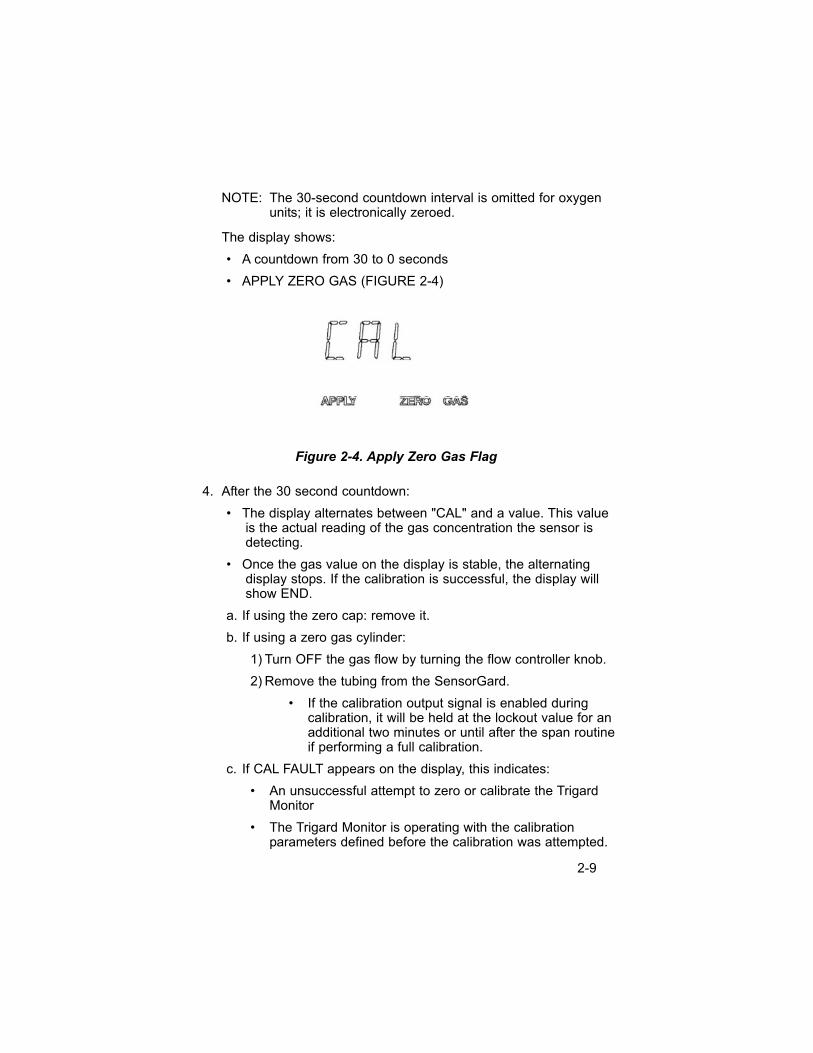
• A countdown from 30 to 0 seconds
• APPLY ZERO GAS (FIGURE 2-4)
1).
4. After the 30 second countdown:
• The display alternates between "CAL" and a value. This valueis the actual reading of the gas concentration the sensor isdetecting.
• Once the gas value on the display is stable, the alternatingdisplay stops. If the calibration is successful, the display willshow END.
a. If using the zero cap: remove it.
b. If using a zero gas cylinder:
1) Turn OFF the gas flow by turning the flow controller knob.
2) Remove the tubing from the SensorGard.
• If the calibration output signal is enabled duringcalibration, it will be held at the lockout value for anadditional two minutes or until after the span routineif performing a full calibration.
c. If CAL FAULT appears on the display, this indicates:
• An unsuccessful attempt to zero or calibrate the TrigardMonitor
• The Trigard Monitor is operating with the calibrationparameters defined before the calibration was attempted.
Figure 2-4. Apply Zero Gas Flag
2-9

• See Troubleshooting Guidelines found in Chapter 5.
To extinguish the CAL FAULT, a complete, successfulcalibration procedure must be performed.
The Trigard Monitor allows automatic zero adjustment only within apre-defined range. It cannot make corrections outside this range,such as when an empty or wrong cylinder of gas is applied orfailure to begin gas flow within the allotted 30-second countdownoccurs.
• If only a ZERO was performed, the procedure is complete andthe user should return the calibration equipment to the cal kit. Ifa CAL was performed, the gas monitor will continue to the"span" sequence as described in the following section.
Spanning
5. During a regular calibration, the Trigard Monitor automaticallybegins the span countdown after a successful zeroing of the unit.The span countdown is 30 seconds (FIGURE 2-5).
NOTE: The span process can be aborted at any time during thecountdown by simply pressing any button on the Calibratorwhile aiming it at the unit or by pressing and releasing thepush-button.
1).
6. Locate the span gas cylinder and the Calibration Kit FlowController.
7. Screw the Flow Controller onto the top of the span gas cylinder.
8. Locate the Tube Assembly from the cal kit.
9. Push the smaller end of the Tube Assembly over the gas outlet ofthe Flow Controller and ensure that the tubing completely coversthe gas outlet.
Figure 2-5. Apply SPAN Gas Flag
2-10

10.When using Cal Kit 40, connect the other end of the tubing overthe SensorGard inlet.
When using Cal Kit 41, locate the cal cap (with hole for tubing) andpush the tubing through the hole in the bottom of the cap. Then,connect the end of the tubing over the sensor inlet and push thecalibration cap over the entire sensor inlet.
11. Turn ON the gas flow by turning the flow controller knob.
• It is good practice to have all calibration components previouslyassembled.
• Ensure that any calibration gases are applied during the 30-second count down period.
• If a CAL FAULT indication is on the Trigard Monitor displaybefore the user is able to apply the gas, a steady state gascondition was reached, causing the unit to use a wrongreading as a span indication.
• It is necessary to restart the calibration process to clear thiscondition.
12. After the 30 second countdown:
• The display alternates between "CAL" and a value. This valueis the actual reading of the gas concentration the sensor isdetecting.
• Once the gas value on the display is stable, the alternatingdisplay stops. If the calibration is successful, the display willshow END for approximately two seconds. (FIGURE 2-6).
• No user adjustments are necessary.
• The display will show the span gas value while the span gas isflowing to the unit.
1).
13.Turn OFF the gas flow by turning the knob on the flow controller.
• If the calibration output signal is enabled during calibration, itwill be held at the lockout value for two additional minutes afterEND is displayed.
• When the span gas is removed from the sensor, the sensorreading should change to show an ambient condition.
Figure 2-6. Calibration End Display
2-11

• If a CAL FAULT appears on the display, this indicates:
• An unsuccessful attempt to calibrate the Trigard Monitor
• The Trigard Monitor is operating with the calibrationparameters defined before the calibration was attempted.
To extinguish the CAL FAULT flag, a complete calibrationprocedure must be performed.
The Trigard Monitor allows automatic zero and span adjustmentswithin a pre-defined range. It cannot make corrections outside thisrange, such as when an empty or wrong cylinder of gas is appliedor failure to begin gas flow within the allotted 30-second countdownoccurs.
14.After a successful calibration, remove the tubing from the FlowController and remove the Flow Controller from the cylinder; returnall items to their appropriate location in the Calibration Kit.
Calibration Documentation
The Trigard Monitor records the date of the last successful calibration.This date can then be displayed on the front-panel LCD (with the use ofthe Controller).
2-12

Chapter 3, Start-up and Calibration for MODBUS output
Typical ModBUS Network Topography (FIGURE 3-1).
Sensors
• A network can consist of up to 31 monitors.
• Each monitor can support up to three sensors.
• Total number of sensors is 93.
Wiring
Power
• Maximum power cable length depends on sensor configuration andwire gauge (TABLES 3-1, 3-2 and 3-3).
RS485 Communications
• Three-wire cable, 22 AWG is labeled:
• A = Transmit + / Receive +
• B = Transmit - / Receive -
• C = Common
• Typical Communications Wiring Scheme (see FIGURE 3-2)
• Maximum RS-485 communications cable length:
• Trunk: 3000 feet
• Branch: 60 feet
• Use line termination devices to match communication linecharacteristics (typically 120 Ohms).
Transmitter Sensor Distance
• Maximum transmitter-sensor distance is 100 feet.
3-1

Figure 3-1. Typical ModBUS Network Topography
3-2

Table 3-1. Maximum Power Cable Length
CONFIGURATION MAXIMUM POWER CABLE LENGTH (IN FEET) (WITH NOMINAL 24-VDC TRANSMITTER SUPPLY)
CATALYTIC XIR E-CHEM 16 AWG CABLE 14 AWG 12 AWG [4.2 OHM [2.6 OHM [1.8 OHMPER 1K FT.] PER 1K FT.] PER 1K FT.]
NO RELAY NO RELAY NO RELAY RELAYS- OPTION- RELAYS OPTION RELAYS OPTION
0 0 3 4500 3500 7500 5500 10,000 7,500
0 2 1 2000 1500 2750 2500 4,000 3,500
0 1 2 3000 2250 4500 3500 6,250 5,000
1 0 2 3500 2750 5500 4250 7,500 6,000
1 1 1 2000 1500 2750 2500 4,000 3,500
2 0 1 2500 1850 3500 3000 5,000 4,000
3 0 0 2000 1500 2750 2500 3,750 3,500
Daisy chaining power to multiple sensors is not recommended.
Table 3-2. Transmitter Power Consumption (7-30 VDC Supply)
CONFIGURATION MAX. POWER MAX. POWERCONSUMPTION CONSUMPTION
CATALYTIC XIR* E-CHEM* WITH RELAYS CLOSED WITH RELAYS OPEN
0 0 3 2.5 W 1.5W
0 2 1 9.5 W 8.5W
0 1 2 7.0 W 6.0 W
1 0 2 6.0 W 5.0 W
1 1 1 6.5 W 5.5 W
2 0 1 8.0 W 7.0 W
3 0 0 10.0 W 9.0 W
*Combinations shown represent maximum loads that may be powered from one transmitter without remote power.
NOTE: Only use single catalytic or XIR sensor configuration with 7 W power supply.
If at least one sensor has remote power, any combination is available.
Recommended power supply selection is for operation not to exceed 65% of capacity.
See Installation Outline Drawings for details.
Table 3-3. Remote Sensor Power Consumption (AC or DC Operation)
SENSOR TYPE MAXIMUM POWER CONSUMPTION
Catalytic 4.5 W
XIR 5.0 W
E-Chem 1.5 W
3-3

Figure 3-2. Typical Communications Wiring Scheme
3-4

Typical Communication Cable Wiring
Operation
Display:
• Displays sensor type and gas level for each sensors
• Cycles through the sensors
• Sensor number graphic identifies sensor number (see FIGURE 3-3)
• Latches on an Alarm or Fault condition and requires useracknowledgment prior to resuming cycling
• If multiple conditions exist, reveals the subsequent alarm/faultcondition when one condition is acknowledged
• Resumes cycling through display screens when all conditions areacknowledged.
• Alarm and fault conditions are indicated by alarm and thecorresponding number of the alarm level(s) that are activated
Relays:
• Gas processing and alarm activation continues even when adisplay is locked on a screen
• Are common to all sensors by default
• Can be assigned specifically to a sensor by enabling only one levelof alarm for each sensor
• This may be accomplished through an Ultima Controller (see "Calibration" later in this chapter) consistent with theexisting Trigard procedures or through a ModBUS controller
• Form C contacts, 5 A resistive, 30 VDC, 250 VAC
• May be configured as
• Normally energized/de-energized
• Increasing/decreasing level alarm
• Latching/non-latching
3-5

Figure 3-3. Sensor Display Screens
3-6

Sensor:
• Automatically recognized when connected to a transmitter
• When removed, causes a "Sensor Missing" fault; this can becorrected by:• Reconnecting a sensor to that position or• Manually taking the sensor 'off-line' via:
• Ultima Controller, by sending a sensor disable command
• ModBUS command write to a control register.
• A missing sensor or unused sensor position returns a gas value of-99.9 in response to a ModBUS request for gas level value startingat address base +207.
Alarm Status Screen
(FIGURE 3-4)
In the North American version, a screen will appear when a combustiblesensor crosses 50%, 60% or 90% of the full-scale range.
• This screen:
• will override all sensor data or fault screens and will clear whenall sensors are below 50% of scale.
• can be acknowledged by the operator; the:
• instrument will go back to normal display operation until thesensor or any other sensor crosses 50%, 60% or 90% ofscale
• normal operation status screen will display again.
• can be acknowledged through the:
• Ultima Controller
• Pushbutton or
• MODBUS interface.
NOTE: All IR inputs will be functional and appropriate displayscreens will display for the received IR message.
3-7
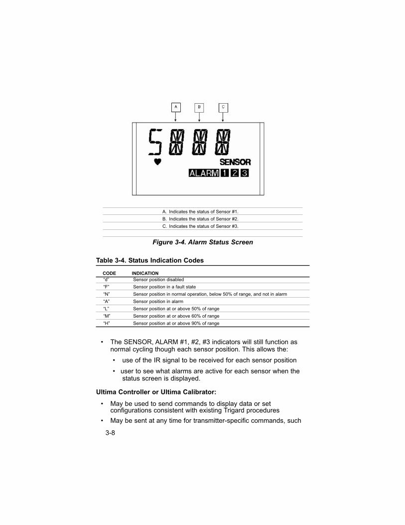
Table 3-4. Status Indication Codes
CODE INDICATION
“d” Sensor position disabled
“F” Sensor position in a fault state
“N” Sensor position in normal operation, below 50% of range, and not in alarm
“A” Sensor position in alarm
“L” Sensor position at or above 50% of range
“M” Sensor position at or above 60% of range
“H” Sensor position at or above 90% of range
• The SENSOR, ALARM #1, #2, #3 indicators will still function asnormal cycling though each sensor position. This allows the:
• use of the IR signal to be received for each sensor position
• user to see what alarms are active for each sensor when thestatus screen is displayed.
Ultima Controller or Ultima Calibrator:
• May be used to send commands to display data or setconfigurations consistent with existing Trigard procedures
• May be sent at any time for transmitter-specific commands, such
A. Indicates the status of Sensor #1.
B. Indicates the status of Sensor #2.
C. Indicates the status of Sensor #3.
Figure 3-4. Alarm Status Screen
3-8

as address, baud rate, etc.
• Sensor-specific commands (such as calibration initiation or span value) must be sent while thesensor data (sensor type or gas levels) is displayed
Calibration
Calibration is performed via the:
• Ultima Controller• Sends a zero or span command
• Sensor calibration depends on the sensor number showing onthe display when the command is received.
• Push-button
• Depends on the sensor number showing on the display whenthe command is received.
• Press and release push-button to acknowledge any conditions
• With the desired sensor data (sensor or gas level) on thedisplay, press the push-button to activate a calibration
• Calibration function depends on length of time that the push-button is pressed• 5 seconds: zero calibration• 10 seconds: span calibration• 20 seconds: factory initial calibration
• Push-button included.
• See Installation Outline Drawings for details.
Figure 3-5. ModBus PCB
3-9

• ModBUS Port
• See ModBUS data table definition in this addendum.
During the calibration process, the transmitter is inMaintenance mode, all alarming is inhibited for all sensors,and transmitter will not alert user to potential hazardous sit-uations.
• During the calibration of a sensor, a ModBUS request for the gaslevel returns the actual value. The other sensors on that specifictransmitter are not active. A gas level of -99.9 will be returned toindicate that.
ModBUS Communications
Baud rate and data format defaults per data table specification areadjustable by using a:
• Hand-held Controller or
• ModBUS command.
Each transmitter:
• Is a slave on the communications network
• Must have a unique address and serial format compatible withtransmitter configuration.
ModBUS Addressing
The ModBUS slave address has a valid range of 1-247.
• 247 is the default value.
This address may be set by:
• The Ultima Controller:
• Send an address command with the desired value.
• The Ultima Calibrator:
• Press the ADDRESS button once to display the current setting.
• The ZERO button increments the address number
• The SPAN button decrements the address number
• Range for Calibrator is 1 - 32; use Controller for otheraddresses
" WARNING
3-10
• Press the ADDRESS button again to save the new address.
• A ModBUS controller by writing to the corresponding register in thedata table.
ModBUS Communications
• The communications protocol is ModBUS RTU over an RS-485hardware network.
• The default settings for communications parameters are 19200baud and even parity.
• The stop bits are fixed at 1 stop bit.
• For data types that are larger than one word, the most significantword is located in the first register (big-endian).
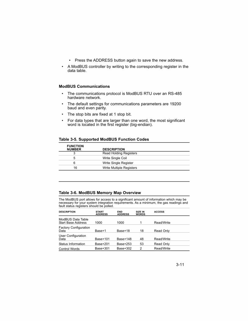
Table 3-5. Supported ModBUS Function Codes
FUNCTIONNUMBER DESCRIPTION
3 Read Holding Registers
5 Write Single Coil
6 Write Single Register
16 Write Multiple Registers
Table 3-6. ModBUS Memory Map Overview
The ModBUS port allows for access to a significant amount of information which may benecessary for your system integration requirements. As a minimum, the gas readings andfault status registers should be polled.
DESCRIPTION START END SIZE IN ACCESSADDRESS ADDRESS WORDS
ModBUS Data Table Start Base Address 1000 1000 1 Read/Write
Factory Configuration Data Base+1 Base+18 18 Read Only
User ConfigurationData Base+101 Base+148 48 Read/Write
Status Information Base+201 Base+253 53 Read Only
Control Words Base+301 Base+302 2 Read/Write
3-11
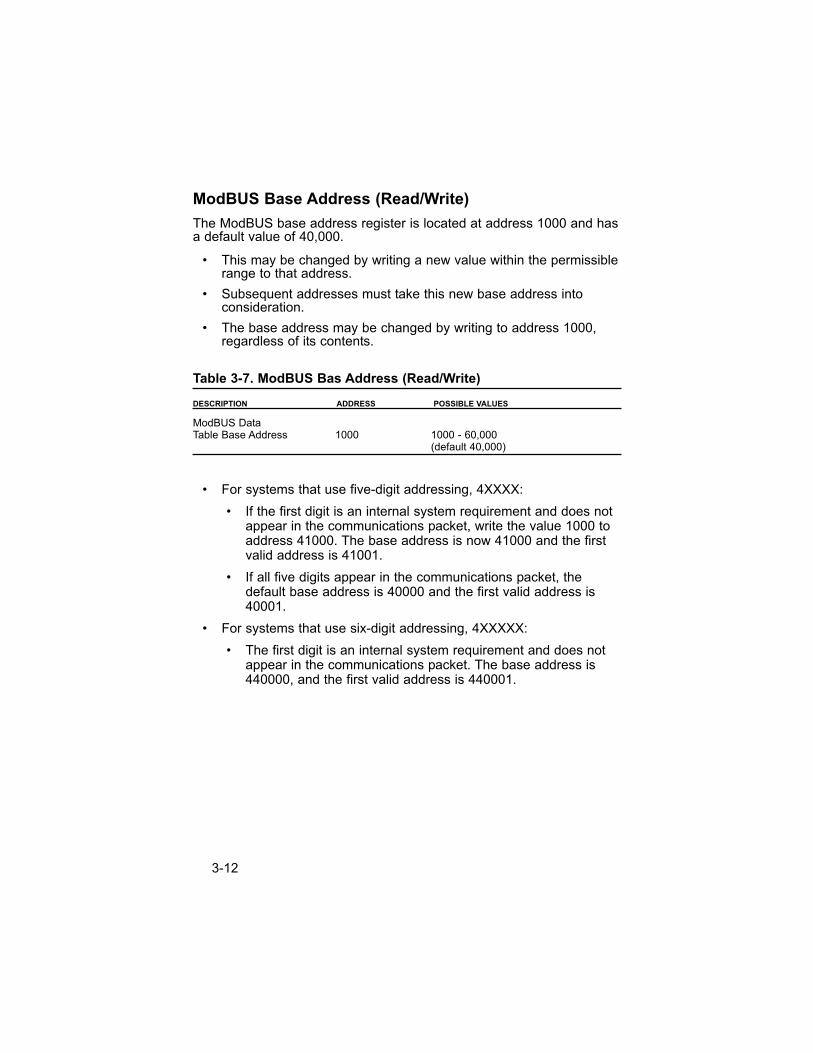
ModBUS Base Address (Read/Write)
The ModBUS base address register is located at address 1000 and hasa default value of 40,000.
• This may be changed by writing a new value within the permissiblerange to that address.
• Subsequent addresses must take this new base address intoconsideration.
• The base address may be changed by writing to address 1000,regardless of its contents.
Table 3-7. ModBUS Bas Address (Read/Write)
DESCRIPTION ADDRESS POSSIBLE VALUES
ModBUS Data Table Base Address 1000 1000 - 60,000
(default 40,000)
• For systems that use five-digit addressing, 4XXXX:
• If the first digit is an internal system requirement and does notappear in the communications packet, write the value 1000 toaddress 41000. The base address is now 41000 and the firstvalid address is 41001.
• If all five digits appear in the communications packet, thedefault base address is 40000 and the first valid address is40001.
• For systems that use six-digit addressing, 4XXXXX:
• The first digit is an internal system requirement and does notappear in the communications packet. The base address is440000, and the first valid address is 440001.
3-12
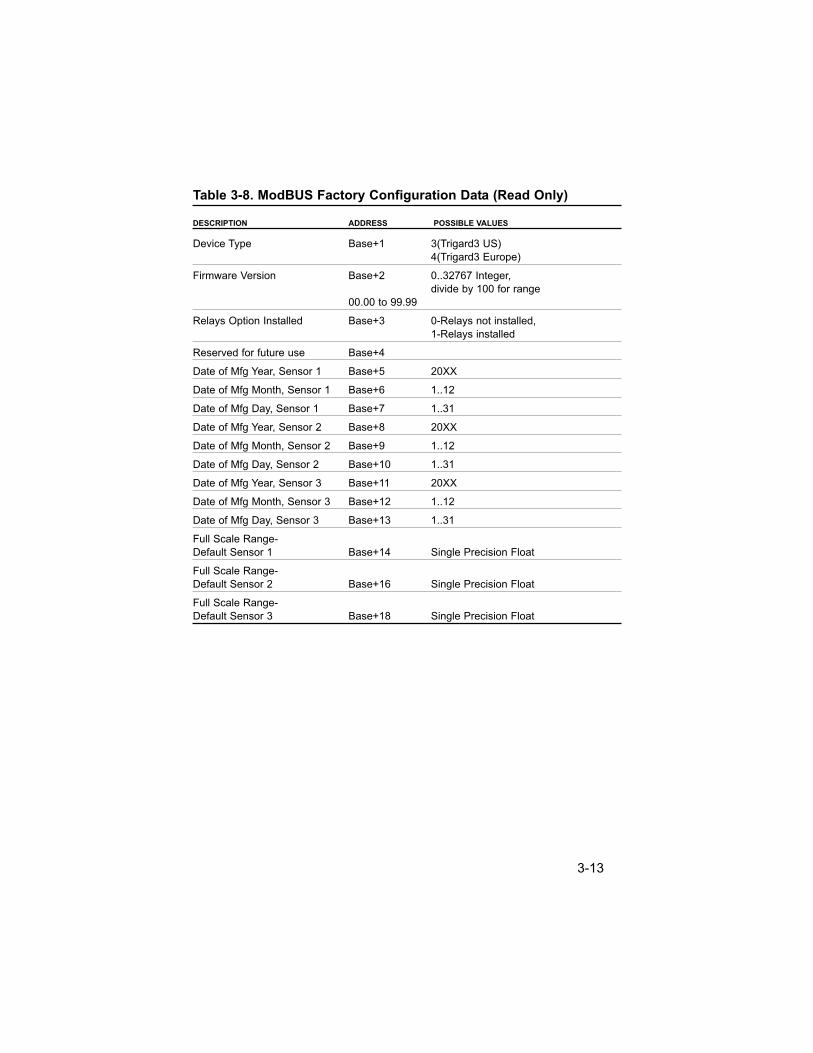
Table 3-8. ModBUS Factory Configuration Data (Read Only)
DESCRIPTION ADDRESS POSSIBLE VALUES
Device Type Base+1 3(Trigard3 US)
4(Trigard3 Europe)
Firmware Version Base+2 0..32767 Integer,
divide by 100 for range
00.00 to 99.99
Relays Option Installed Base+3 0-Relays not installed,
1-Relays installed
Reserved for future use Base+4
Date of Mfg Year, Sensor 1 Base+5 20XX
Date of Mfg Month, Sensor 1 Base+6 1..12
Date of Mfg Day, Sensor 1 Base+7 1..31
Date of Mfg Year, Sensor 2 Base+8 20XX
Date of Mfg Month, Sensor 2 Base+9 1..12
Date of Mfg Day, Sensor 2 Base+10 1..31
Date of Mfg Year, Sensor 3 Base+11 20XX
Date of Mfg Month, Sensor 3 Base+12 1..12
Date of Mfg Day, Sensor 3 Base+13 1..31
Full Scale Range-
Default Sensor 1 Base+14 Single Precision Float
Full Scale Range-
Default Sensor 2 Base+16 Single Precision Float
Full Scale Range-
Default Sensor 3 Base+18 Single Precision Float
3-13
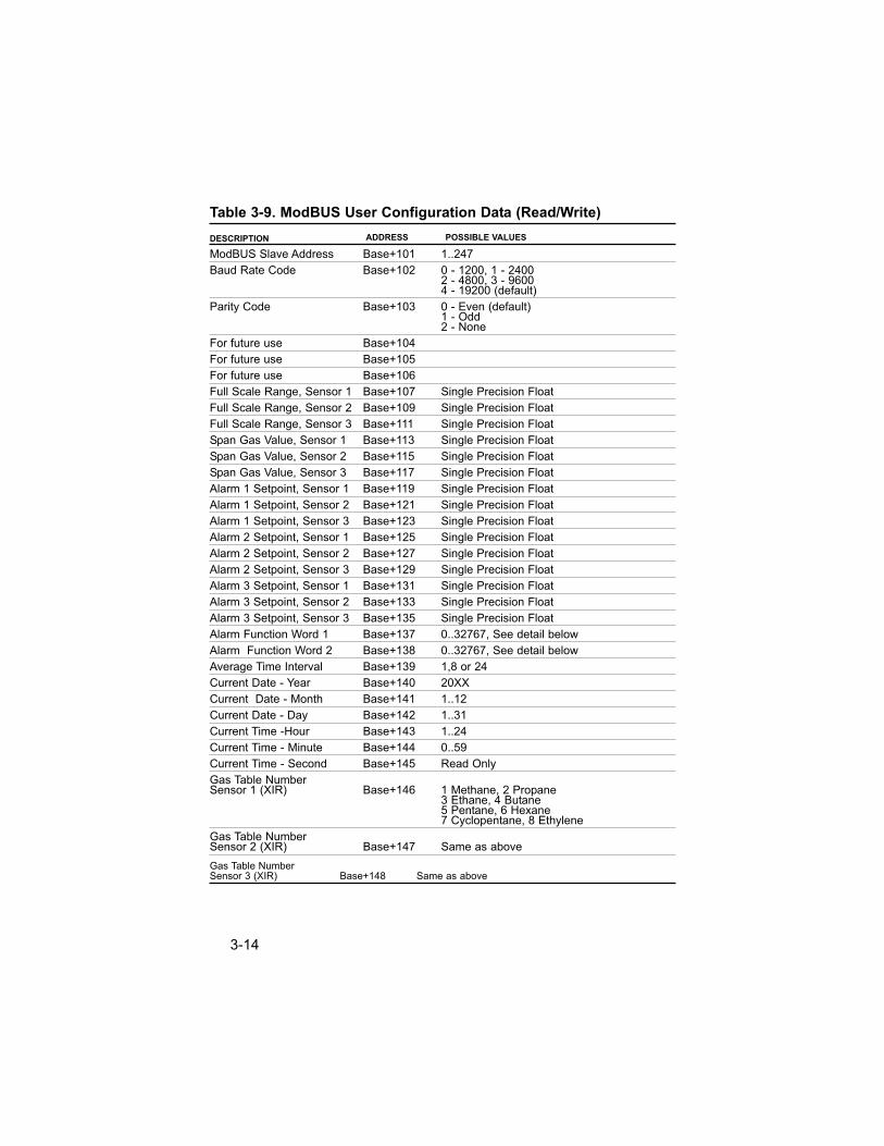
Table 3-9. ModBUS User Configuration Data (Read/Write)
DESCRIPTION ADDRESS POSSIBLE VALUES
ModBUS Slave Address Base+101 1..247
Baud Rate Code Base+102 0 - 1200, 1 - 24002 - 4800, 3 - 96004 - 19200 (default)
Parity Code Base+103 0 - Even (default) 1 - Odd2 - None
For future use Base+104
For future use Base+105
For future use Base+106
Full Scale Range, Sensor 1 Base+107 Single Precision Float
Full Scale Range, Sensor 2 Base+109 Single Precision Float
Full Scale Range, Sensor 3 Base+111 Single Precision Float
Span Gas Value, Sensor 1 Base+113 Single Precision Float
Span Gas Value, Sensor 2 Base+115 Single Precision Float
Span Gas Value, Sensor 3 Base+117 Single Precision Float
Alarm 1 Setpoint, Sensor 1 Base+119 Single Precision Float
Alarm 1 Setpoint, Sensor 2 Base+121 Single Precision Float
Alarm 1 Setpoint, Sensor 3 Base+123 Single Precision Float
Alarm 2 Setpoint, Sensor 1 Base+125 Single Precision Float
Alarm 2 Setpoint, Sensor 2 Base+127 Single Precision Float
Alarm 2 Setpoint, Sensor 3 Base+129 Single Precision Float
Alarm 3 Setpoint, Sensor 1 Base+131 Single Precision Float
Alarm 3 Setpoint, Sensor 2 Base+133 Single Precision Float
Alarm 3 Setpoint, Sensor 3 Base+135 Single Precision Float
Alarm Function Word 1 Base+137 0..32767, See detail below
Alarm Function Word 2 Base+138 0..32767, See detail below
Average Time Interval Base+139 1,8 or 24
Current Date - Year Base+140 20XX
Current Date - Month Base+141 1..12
Current Date - Day Base+142 1..31
Current Time -Hour Base+143 1..24
Current Time - Minute Base+144 0..59
Current Time - Second Base+145 Read Only
Gas Table NumberSensor 1 (XIR) Base+146 1 Methane, 2 Propane
3 Ethane, 4 Butane5 Pentane, 6 Hexane7 Cyclopentane, 8 Ethylene
Gas Table NumberSensor 2 (XIR) Base+147 Same as above
Gas Table NumberSensor 3 (XIR) Base+148 Same as above
3-14

Table 3-10. Alarm Function Codes - Word 1(Read/Write at Address Base+137)
NAME BITS FUNCTION DESCRIPTION
Alarm 1 Enable, Sensor 1 0 1-Enable, 0-Disable
Alarm 1 Enable, Sensor 2 1 1-Enable, 0-Disable
Alarm 1 Enable, Sensor 3 2 1-Enable, 0-Disable
Alarm 2 Enable, Sensor 1 3 1-Enable, 0-Disable
Alarm 2 Enable, Sensor 2 4 1-Enable, 0-Disable
Alarm 2 Enable, Sensor 3 5 1-Enable, 0-Disable
Alarm 3 Enable, Sensor 1 6 1-Enable, 0-Disable
Alarm 3 Enable, Sensor 2 7 1-Enable, 0-Disable
Alarm 3 Enable, Sensor 3 8 1-Enable, 0-Disable
Alarm 1 Direction, Sensor 1 9 1-Increasing, 0-Decreasing
Alarm 1 Direction, Sensor 2 10 1-Increasing, 0-Decreasing
Alarm 1 Direction, Sensor 3 11 1-Increasing, 0-Decreasing
Alarm 2 Direction, Sensor 1 12 1-Increasing, 0-Decreasing
Alarm 2 Direction, Sensor 2 13 1-Increasing, 0-Decreasing
Alarm 2 Direction, Sensor 3 14 1-Increasing, 0-Decreasing
Not used 15
3-15

Table 3-11. Alarm Function Codes - Word 2(Read/Write at Address Base+138)
NAME BITS FUNCTION DESCRIPTION
Alarm 3 Direction, Sensor 1 0 1-Increasing, 0-Decreasing
Alarm 3 Direction, Sensor 2 1 1-Increasing, 0-Decreasing
Alarm 3 Direction, Sensor 3 2 1-Increasing, 0-Decreasing
Alarm 1 Latch Status, Sensor 1 3 0 - Non-Latching, 1 - Latching
Alarm 1 Latch Status, Sensor 2 4 0 - Non-Latching, 1 - Latching
Alarm 1 Latch Status, Sensor 3 5 0 - Non-Latching, 1 - Latching
Alarm 2 Latch Status, Sensor 1 6 0 - Non-Latching, 1 - Latching
Alarm 2 Latch Status, Sensor 2 7 0 - Non-Latching, 1 - Latching
Alarm 2 Latch Status, Sensor 3 8 0 - Non-Latching, 1 - Latching
Alarm 3 Latch Status, Sensor 1 9 0 - Non-Latching, 1 - Latching
Alarm 3 Latch Status, Sensor 2 10 0 - Non-Latching, 1 - Latching
Alarm 3 Latch Status, Sensor 3 11 0 - Non-Latching, 1 - Latching
Relay State-NO Alarm 12 1 - Normally Energized,0 - Normally De-Energized
Relay State-NO Alarm 13 1 - Normally Energized,0 - Normally De-Energized
Relay State-NO Alarm 14 1 - Normally Energized,0 - Normally De-Energized
Not used 15
3-16

Table 3-12. ModBUS Device Status (Read only)
DESCRIPTION ADDRESS POSSIBLE VALUES
General Status Bits Base+201 0..32767, See details below
Fault Status Bits Base+202 0..32767, See details below
Reserve Base+203
Gas Type - Sensor 1 Base+204 See TABLE 17 for details
Gas Type - Sensor 2 Base+205 See TABLE 17 for details
Gas Type - Sensor 3 Base+206 See TABLE 17 for details
Gas Level - Sensor 1 Base+207 Single Precision Float
Gas Level - Sensor 2 Base+209 Single Precision Float
Gas Level - Sensor 3 Base+211 Single Precision Float
Engineering Units - Sensor 1 Base+213 See TABLE 18 for details
Engineering Units - Sensor 2 Base+214 See TABLE 18 for details
Engineering Units - Sensor 3 Base+215 See TABLE 18 for details
Calibration Step Base+216 0. 30 Sec Countdown to Start Zero
1. Waiting for Zero2. 30 Sec Countdown
to Start SPAN3. Waiting for SPAN4. Calibration Aborted5. Zero Cal Fault6. Span Cal Fault7. Calibration Completed Successfully
Temperature - Sensor 1 Base+217 Signed Integer
Temperature - Sensor 2 Base+218 Signed Integer
Temperature - Sensor 3 Base+219 Signed Integer
Min Gas Reading over average Interval - Sensor 1 Base+220 Single Precision Float
Min Gas Reading over average Interval - Sensor 2 Base+222 Single Precision Float
Min Gas Reading over average Interval - Sensor 3 Base+224 Single Precision Float
Max Gas Reading over average Interval - Sensor 1 Base+226 Single Precision Float
Max Gas Reading over average Interval - Sensor 2 Base+228 Single Precision Float
Max Gas Reading over average Interval - Sensor 3 Base+230 Single Precision Float
Avg Gas Reading over average Interval - Sensor 1 Base+232 Single Precision Float
Avg Gas Reading over average Interval - Sensor 2 Base+234 Single Precision Float
Avg Gas Reading over average Interval - Sensor 3 Base+236 Single Precision Float
3-17
DESCRIPTION ADDRESS POSSIBLE VALUES
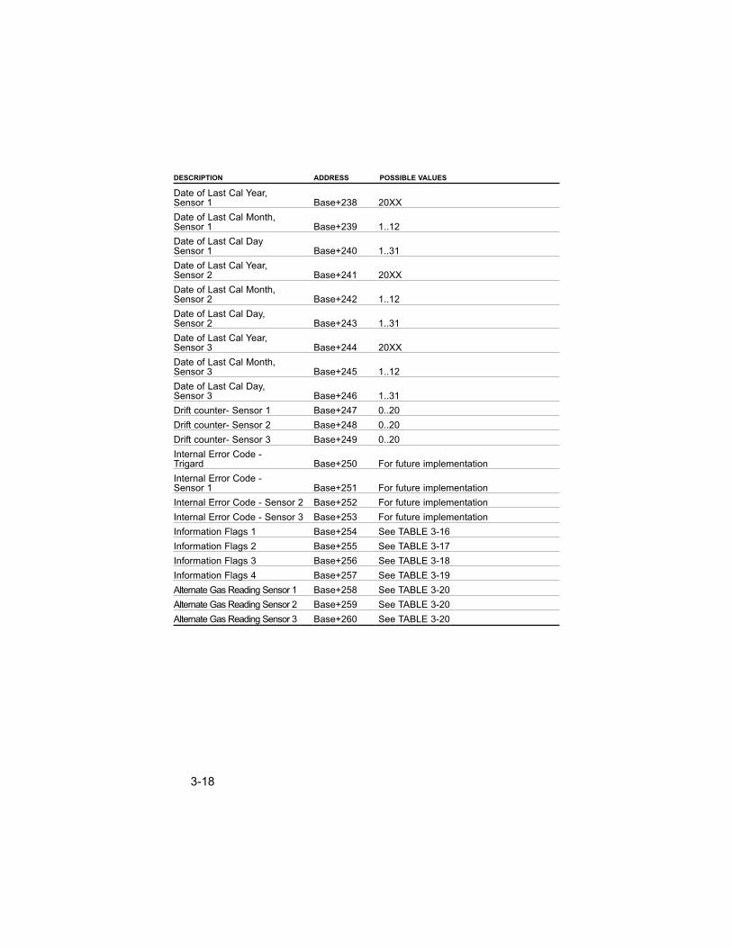
Date of Last Cal Year, Sensor 1 Base+238 20XX
Date of Last Cal Month, Sensor 1 Base+239 1..12
Date of Last Cal Day Sensor 1 Base+240 1..31
Date of Last Cal Year, Sensor 2 Base+241 20XX
Date of Last Cal Month, Sensor 2 Base+242 1..12
Date of Last Cal Day, Sensor 2 Base+243 1..31
Date of Last Cal Year, Sensor 3 Base+244 20XX
Date of Last Cal Month, Sensor 3 Base+245 1..12
Date of Last Cal Day, Sensor 3 Base+246 1..31
Drift counter- Sensor 1 Base+247 0..20
Drift counter- Sensor 2 Base+248 0..20
Drift counter- Sensor 3 Base+249 0..20
Internal Error Code - Trigard Base+250 For future implementation
Internal Error Code - Sensor 1 Base+251 For future implementation
Internal Error Code - Sensor 2 Base+252 For future implementation
Internal Error Code - Sensor 3 Base+253 For future implementation
Information Flags 1 Base+254 See TABLE 3-16
Information Flags 2 Base+255 See TABLE 3-17
Information Flags 3 Base+256 See TABLE 3-18
Information Flags 4 Base+257 See TABLE 3-19
Alternate Gas Reading Sensor 1 Base+258 See TABLE 3-20
Alternate Gas Reading Sensor 2 Base+259 See TABLE 3-20
Alternate Gas Reading Sensor 3 Base+260 See TABLE 3-20
3-18

Table 3-13. ModBUS General Status Bits(Read Only at address Base+201)
NAME BIT FUNCTION DESCRIPTION
Device Fault (any fault) 0 Set for all fault conditions
Calibration Active - Sensor 1 1 Set during calibration
Calibration Active - Sensor 2 2 Set during calibration
Calibration Active - Sensor 3 3 Set during calibration
Warm up Mode 4 Set during startup
Low Alarm Active 5 Set while alarm relay is active
Mid Alarm Active 6 Set while alarm relay is active
High Alarm Active 7 Set while alarm relay is active
For future use 8
For future use 9
For future use 10
For future use 11
For future use 12
For future use 13
For future use 14
Not used 15
Table 3-14. ModBUS Fault Status Bits (Read Only at address Base+202)
NAME BIT FUNCTION DESCRIPTION
Fault Relay Active 0 Set when any fault is detected
Sensor Missing - Sensor 1 1 Set when this fault is detected
Sensor Missing - Sensor 2 2 Set when this fault is detected
Sensor Missing - Sensor 3 3 Set when this fault is detected
Calibration Fault - Sensor 1 4 Set when this fault is detected
Calibration Fault - Sensor 2 5 Set when this fault is detected
Calibration Fault - Sensor 3 6 Set when this fault is detected
Power Fail Fault - Sensor 1 7 Set when this fault is detected
Power Fail Fault - Sensor 2 8 Set when this fault is detected
Power Fail Fault - Sensor 3 9 Set when this fault is detected
Power Fail Fault - Main Unit +5VDC 10 Set when this fault is detected
Sensor End of life - Sensor 1 11 Set when this fault is detected
Sensor End of life - Sensor 2 12 Set when this fault is detected
Sensor End of life - Sensor 3 13 Set when this fault is detected
Trigard Configuration Reset 14 Set when a datasheet reset occurs
Not used 15
3-19
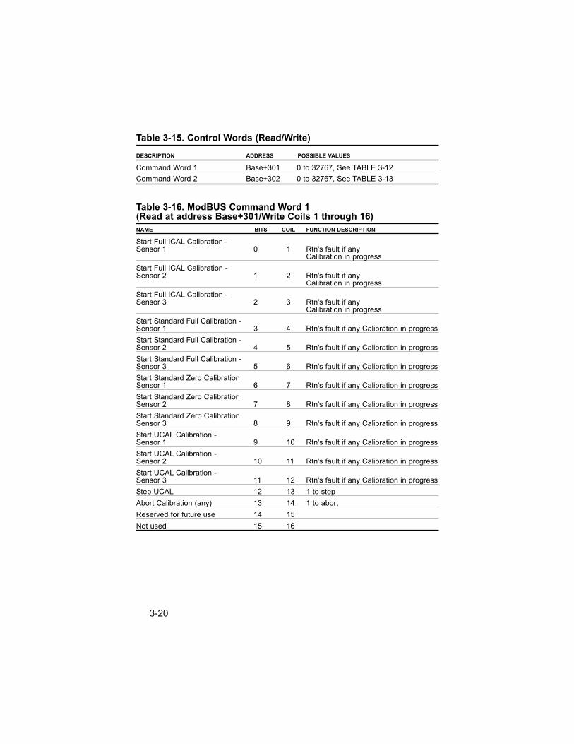
Table 3-15. Control Words (Read/Write)
DESCRIPTION ADDRESS POSSIBLE VALUES
Command Word 1 Base+301 0 to 32767, See TABLE 3-12
Command Word 2 Base+302 0 to 32767, See TABLE 3-13
Table 3-16. ModBUS Command Word 1(Read at address Base+301/Write Coils 1 through 16)
NAME BITS COIL FUNCTION DESCRIPTION
Start Full ICAL Calibration - Sensor 1 0 1 Rtn's fault if any
Calibration in progress
Start Full ICAL Calibration - Sensor 2 1 2 Rtn's fault if any
Calibration in progress
Start Full ICAL Calibration -Sensor 3 2 3 Rtn's fault if any
Calibration in progress
Start Standard Full Calibration - Sensor 1 3 4 Rtn's fault if any Calibration in progress
Start Standard Full Calibration - Sensor 2 4 5 Rtn's fault if any Calibration in progress
Start Standard Full Calibration - Sensor 3 5 6 Rtn's fault if any Calibration in progress
Start Standard Zero Calibration Sensor 1 6 7 Rtn's fault if any Calibration in progress
Start Standard Zero Calibration Sensor 2 7 8 Rtn's fault if any Calibration in progress
Start Standard Zero Calibration Sensor 3 8 9 Rtn's fault if any Calibration in progress
Start UCAL Calibration - Sensor 1 9 10 Rtn's fault if any Calibration in progress
Start UCAL Calibration - Sensor 2 10 11 Rtn's fault if any Calibration in progress
Start UCAL Calibration - Sensor 3 11 12 Rtn's fault if any Calibration in progress
Step UCAL 12 13 1 to step
Abort Calibration (any) 13 14 1 to abort
Reserved for future use 14 15
Not used 15 16
3-20

Table 13-17 ModBUS Command Word 2(Read at address Base+302/Write Coils 17 through 32)
NAME BIT COIL FUNCTION DESCRIPTION
Sensor Swap Delay 0 17 1-Enable, 0-Disable
Alert Option Enable 1 18 1-Enable, 0-Disable
Acknowledge or Reset Latched Alarms(ACK) 2 19 1 to initiate (same functionality as Push-
button or IR command)
Reset Main Board and sensors 3 20 1 to initiate
For future use 4 21
For future use 5 22
Reset Data Sheet - Sensor 1 6 23 1 to initiate
Reset Data Sheet - Sensor 2 7 24 1 to initiate
Reset Data Sheet - Sensor 3 8 25 1 to initiate
Disable Sensor 1 9 26 1 to Disable
Disable Sensor 2 10 27 1 to Disable
Disable Sensor 3 11 28 1 to Disable
Reserved for future use 12 29
Reserved for future use 13 30
Reserved for future use 14 31
Not used 15 32
3-21

Table 3-18. Sensor Type
SENSOR TYPE VALUE SENSOR TYPE
13 COMB-1S 100% LEL, 1% LEL, 25% LEL (0.6% Propane)
257 CO 100 PPM, 1 PPM, MSA 25E/F, 60 PPM
258 CO 500 PPM, 1 PPM, MSA 25E/F, 300 PPM
259 SO2 25 PPM, 1 PPM, CTL 7ST/F, 10 PPM
260 H2S 10.0 PPM, 0.1 PPM, MSA HS25B, 5.0 PPM
261 H2S 50.0 PPM, 0.1 PPM, MSA HS25B, 40 PPM
262 H2S 100 PPM, 1 PPM, MSA HS25D, 40 PPM
263 NO 100 PPM, 1 PPM, CTL 7NT, 50 PPM
264 NO2 10.0 PPM, 0.1 PPM, MSA ND25C, 5.0 PPM
265 CL2 5.0 PPM, 0.1 PPM, MSA CL25B, 2.0 PPM
266 HCN 50 PPM, 1 PPM, MSA HN25C, 10 PPM
267 HCL 50 PPM, 1 PPM, MSA HL25C, 40 PPM
12 O2 25.0%, 0.1%, MSA 10019727, 20.8%
14 COMB-1S 100%LEL, 1% LEL, 40% LEL
15 COMB-1S 100%LEL, 1% LEL, 55% LEL
16 COMB-1S-NL 100%LEL, 1% LEL, 25% LEL
17 COMB-1S-NL 100%LEL, 1% LEL, 40% LEL
18 COMB-1S-NL 100%LEL, 1% LEL, 55% LEL
19 CLO2 3.0 PPM, 0.1 PPM, MSA 7CLH, 1.0 PPM
276 NH3 100 PPM, 1 PPM, SENSORIC, 25 PPM
277 H2, 1000 PPM, 10 PPM, CTL 7HYT, 300 PPM
279 PHOSPHINE, 2.0 PPM, 0.1 PPM CTL 7SH, 0.5 PPM
280 ARSINE, 2.0 PPM, 0.1 PPM, CTL 7SH, 1.0 PPM
281 SILANE, 25 PPM, 1 PPM, CTL 7SH, 5 PPM
282 GERMANE, 3.0 PPM, 0.1 PPM, CTL 7SH, 2.5 PPM
283 DIBORANE, 50 PPM, 1 PPM, CTL 7SH, 15 PPM
284 FLUORINE, 5.0 PPM, 0.1 PPM, MSA 7CLH, 4.0 PPM
285 HF
286 BROMINE, 5.0 PPM, 0.1 PPM, MSA 7CLH, 2.5 PPM
287 ETO, 10.0 PPM, 0.1 PPM, 5 PPM
288 O2 10.0%, 0.1% MSA 10019727, 5.0%
2 IRIS
19 COMB-1S-100% LEL, 10% LEL, 31% LEL
20 COMB-1S-100% LEL, 1% LEL, 49% LEL
21 COMB-1S-100% LEL, 1% LEL, 68% LEL
3-22
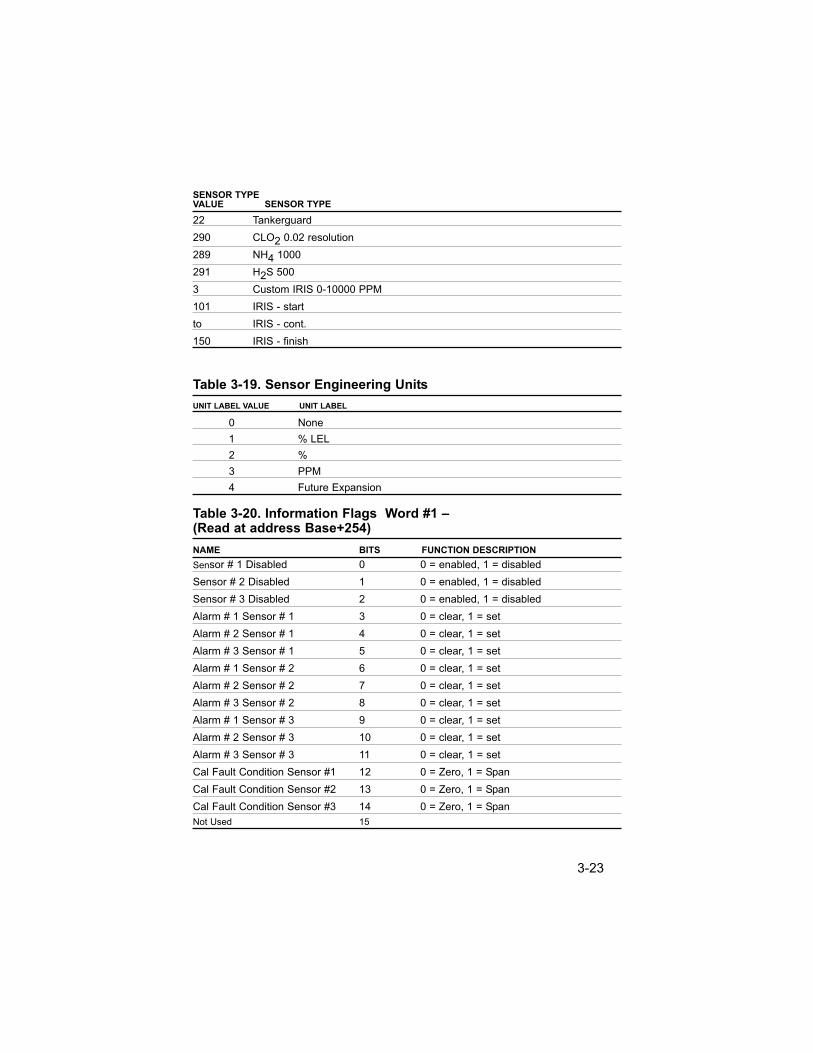
SENSOR TYPE VALUE SENSOR TYPE
22 Tankerguard
290 CLO2 0.02 resolution
289 NH4 1000
291 H2S 500
3 Custom IRIS 0-10000 PPM
101 IRIS - start
to IRIS - cont.
150 IRIS - finish
Table 3-19. Sensor Engineering Units
UNIT LABEL VALUE UNIT LABEL
0 None
1 % LEL
2 %
3 PPM
4 Future Expansion
Table 3-20. Information Flags Word #1 – (Read at address Base+254)
NAME BITS FUNCTION DESCRIPTION
Sensor # 1 Disabled 0 0 = enabled, 1 = disabled
Sensor # 2 Disabled 1 0 = enabled, 1 = disabled
Sensor # 3 Disabled 2 0 = enabled, 1 = disabled
Alarm # 1 Sensor # 1 3 0 = clear, 1 = set
Alarm # 2 Sensor # 1 4 0 = clear, 1 = set
Alarm # 3 Sensor # 1 5 0 = clear, 1 = set
Alarm # 1 Sensor # 2 6 0 = clear, 1 = set
Alarm # 2 Sensor # 2 7 0 = clear, 1 = set
Alarm # 3 Sensor # 2 8 0 = clear, 1 = set
Alarm # 1 Sensor # 3 9 0 = clear, 1 = set
Alarm # 2 Sensor # 3 10 0 = clear, 1 = set
Alarm # 3 Sensor # 3 11 0 = clear, 1 = set
Cal Fault Condition Sensor #1 12 0 = Zero, 1 = Span
Cal Fault Condition Sensor #2 13 0 = Zero, 1 = Span
Cal Fault Condition Sensor #3 14 0 = Zero, 1 = Span
Not Used 15
3-23
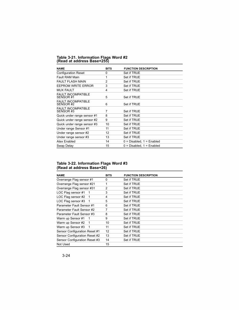
Table 3-21. Information Flags Word #2 (Read at address Base+255)
NAME BITS FUNCTION DESCRIPTION
Configuration Reset 0 Set if TRUE
Fault RAM Main 1 Set if TRUE
FAULT FLASH MAIN 2 Set if TRUE
EEPROM WRITE ERROR 3 Set if TRUE
MUX FAULT 4 Set if TRUE
FAULT INCOMPATIBLE SENSOR #1 5 Set if TRUE
FAULT INCOMPATIBLE SENSOR #2 6 Set if TRUE
FAULT INCOMPATIBLE SENSOR #3 7 Set if TRUE
Quick under range sensor #1 8 Set if TRUE
Quick under range sensor #2 9 Set if TRUE
Quick under range sensor #3 10 Set if TRUE
Under range Sensor #1 11 Set if TRUE
Under range sensor #2 12 Set if TRUE
Under range sensor #3 13 Set if TRUE
Atex Enabled 14 0 = Disabled, 1 = Enabled
Swap Delay 15 0 = Disabled, 1 = Enabled
Table 3-22. Information Flags Word #3 (Read at address Base+26)
NAME BITS FUNCTION DESCRIPTION
Overrange Flag sensor #1 0 Set if TRUE
Overrange Flag sensor #21 1 Set if TRUE
Overrange Flag sensor #31 2 Set if TRUE
LOC Flag sensor #1 1 3 Set if TRUE
LOC Flag sensor #2 1 4 Set if TRUE
LOC Flag sensor #3 1 5 Set if TRUE
Parameter Fault Sensor #1 6 Set if TRUE
Parameter Fault Sensor #2 7 Set if TRUE
Parameter Fault Sensor #3 8 Set if TRUE
Warm up Sensor #1 1 9 Set if TRUE
Warm up Sensor #2 1 10 Set if TRUE
Warm up Sensor #3 1 11 Set if TRUE
Sensor Configuration Reset #1 12 Set if TRUE
Sensor Configuration Reset #2 13 Set if TRUE
Sensor Configuration Reset #3 14 Set if TRUE
Not Used 15
3-24

Table 3-23. Information Flags Word #4 (Read at address Base+257)
NAME BITS FUNCTION DESCRIPTION
Underrange Average Interval S1 0 Set if TRUE
Underrange Average Interval S2 1 Set if TRUE
Underrange Average Interval S3 2 Set if TRUE
Overrange Average Interval S1 3 Set if TRUE
Overrange Average Interval S2 4 Set if TRUE
Overrange Average Interval S3 5 Set if TRUE
Sensor Warning Sensor #1 6 Set if TRUE
Sensor Warning Sensor #2 7 Set if TRUE
Sensor Warning Sensor #3 8 Set if TRUE
Not Used 9
Not Used 10
Not Used 11
Not Used 12
Not Used 13
Not Used 14
Not Used 15
Table 3-24. Alternate Gas Readings (Read/Write at address Base+258 to Base+260)
DESCRIPTION VALUE
Normal Gas Detection 400-2000
Fault 230
Overrange 2110
Suppressed 305
Disabled 0
3-25

Chapter 4, Additional Features
Internal Relays
General Information
The internal relays are designed to enable Trigard Gas Monitors tocontrol other equipment. There are four relays within the Trigard GasMonitor’s module:
• three alarm relays
• one fault relay.
Once configured, the relays activate when the Trigard Gas Monitordetects an alarm condition. Similarly, the fault relay de-energizes whena fault condition is detected.
• The internal relays will be within the read-out module.
The alarm relays are enabled in the non-latching, de-energized mode atthe factory.
• To disable or configure the alarms, you need the Ultima Controller(P/N 809086).
• The fault relay is normally-energized so the relay de-activates intoa fail-safe condition if a fault or power outage occurs. See "FaultRelay" later in this chapter.
To prevent false alarms in the following instances,alarms/relays are temporarily disabled:
1) During the first minute from power-up
2) During calibration
3) For two minutes after calibration.
Installing the Trigard Gas Monitor with Internal Relays
Unpack, mount and wire the Trigard Gas Monitor according to Chapter1, "Set-up." All electrical connections to the Trigard Gas Monitor can bemade via the clearly marked board-mounted connections.
" WARNING
4-1
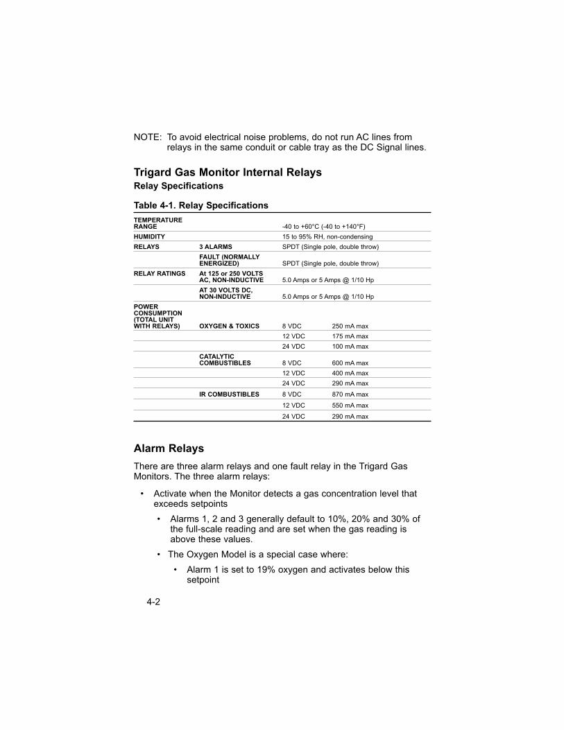
NOTE: To avoid electrical noise problems, do not run AC lines fromrelays in the same conduit or cable tray as the DC Signal lines.
Trigard Gas Monitor Internal RelaysRelay Specifications
Table 4-1. Relay Specifications
TEMPERATURE RANGE -40 to +60°C (-40 to +140°F)
HUMIDITY 15 to 95% RH, non-condensing
RELAYS 3 ALARMS SPDT (Single pole, double throw)
FAULT (NORMALLY ENERGIZED) SPDT (Single pole, double throw)
RELAY RATINGS At 125 or 250 VOLTSAC, NON-INDUCTIVE 5.0 Amps or 5 Amps @ 1/10 Hp
AT 30 VOLTS DC,NON-INDUCTIVE 5.0 Amps or 5 Amps @ 1/10 Hp
POWERCONSUMPTION(TOTAL UNITWITH RELAYS) OXYGEN & TOXICS 8 VDC 250 mA max
12 VDC 175 mA max
24 VDC 100 mA max
CATALYTIC COMBUSTIBLES 8 VDC 600 mA max
12 VDC 400 mA max
24 VDC 290 mA max
IR COMBUSTIBLES 8 VDC 870 mA max
12 VDC 550 mA max
24 VDC 290 mA max
Alarm Relays
There are three alarm relays and one fault relay in the Trigard GasMonitors. The three alarm relays:
• Activate when the Monitor detects a gas concentration level thatexceeds setpoints
• Alarms 1, 2 and 3 generally default to 10%, 20% and 30% ofthe full-scale reading and are set when the gas reading isabove these values.
• The Oxygen Model is a special case where:
• Alarm 1 is set to 19% oxygen and activates below thissetpoint
4-2

• Alarm 2 is set to 18% oxygen and activates below thissetpoint
• Alarm 3 is set to 22% oxygen and activates above thissetpoint.
• These default setpoints can be changed or verified via theController.
• See Ultima Controller and Calibrator manual (P/N 813379).
• The Controller can also enable the latching alarm function.
• Are factory-set to a de-energized position.
• All relay connections have a normally-open set of contacts anda normally-closed set of contacts. These contacts are labeledas NCD (normally-closed, de-energized) or NCE (normally-closed, energized).
• The units are shipped with alarm relays factory-set to the de-energized (non-alarm) position and the trouble relay set to theenergized (non-fault) position.
• Upon activation, the relay contacts change state and remainchanged for as long as:
• The alarm condition exists within the Trigard Gas Monitoror
• The latching mode is selected (see "Note on ResettingLatched alarms with Controller or Calibrator" in Chapter 2).
• These defaults can be changed or verified via the UltimaController.
Fault Relay or Trouble
• It is a normally-energized, single-pole, double-throw (SPDT) relay.
• During normal operation, the relay contacts are normally closed(NC) and normally open (NO) as shown in FIGURE 4-1.
• When a fault is detected or power is cut or turned OFF, thesecontacts change as follows:
• normally closed contacts open
• normally open contacts close.
4-3

• Provides an electrical path for fail-safe relay operation. In the eventof any failure, including power loss, the relay will change to a faultcondition.
The Fault Relay can remain STEADY ON or PULSED. These twodifferent modes can communicate different information to any PLC orDCS connected to the fault relay:
1).
• Fault Relay STEADY ON indicates:
• Trigard sensor is not connected properly or
• Trigard Gas Monitor internal fault or
• An inoperative relay.
• Fault Relay PULSED (once per minute) indicates:
• Improper calibration of the Trigard Gas Monitor or
• Trigard Gas Monitor CHECK CAL or CAL FAULT displayed.
FIGURE 4-1. Relay Contacts
4-4
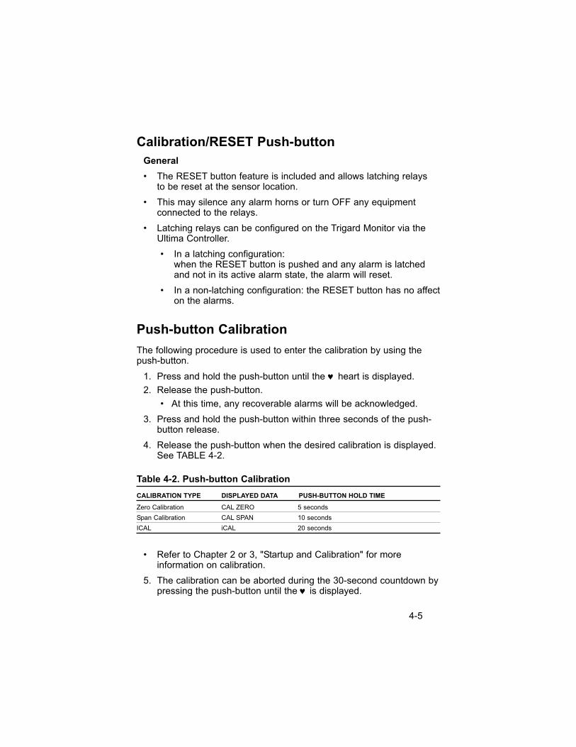
Calibration/RESET Push-button
General
• The RESET button feature is included and allows latching relays to be reset at the sensor location.
• This may silence any alarm horns or turn OFF any equipmentconnected to the relays.
• Latching relays can be configured on the Trigard Monitor via theUltima Controller.
• In a latching configuration:when the RESET button is pushed and any alarm is latchedand not in its active alarm state, the alarm will reset.
• In a non-latching configuration: the RESET button has no affecton the alarms.
Push-button Calibration
The following procedure is used to enter the calibration by using thepush-button.
1. Press and hold the push-button until the ♥ heart is displayed.
2. Release the push-button.
• At this time, any recoverable alarms will be acknowledged.
3. Press and hold the push-button within three seconds of the push-button release.
4. Release the push-button when the desired calibration is displayed.See TABLE 4-2.
Table 4-2. Push-button Calibration
CALIBRATION TYPE DISPLAYED DATA PUSH-BUTTON HOLD TIME
Zero Calibration CAL ZERO 5 seconds
Span Calibration CAL SPAN 10 seconds
ICAL iCAL 20 seconds
• Refer to Chapter 2 or 3, "Startup and Calibration" for moreinformation on calibration.
5. The calibration can be aborted during the 30-second countdown bypressing the push-button until the ♥ is displayed.
4-5
• When the push-button is released, the calibration will beaborted.
Relay Connections
All electrical connections to internal relays can be made directly on thepc board (see FIGURE 4-1).
If you are connecting the relays to motors, fluorescent lighting or otherinductive loads, it is necessary to suppress any sparks or inductivefeedback that may occur at the relay contact. These effects may renderthe unit inoperative. One way to reduce these effects is to install a*Quencharc® across the load being switched. This device is availablefrom MSA as P/N 630413.
In some cases, if strobes are ordered, the relays are pre-wired.
Before wiring the Trigard Gas Monitors, disconnect powersource supplying the monitor; otherwise, electrical shockcould occur.
• The Trigard Gas Monitor must be disassembled for relay wiring
• The following procedure must be performed
1. Remove the Trigard Gas Monitor cover.
2. Pull on the wiring plugs to disconnect the connectors on theexposed board.
NOTE: Observe connector locations for later re-insertion.
3. Route customer-supplied cable into the enclosure and connect tothe appropriate wiring plugs.
4. Identify each conductor of the cable to enable proper connection atthe control equipment.
5. Re-install the wiring plugs.
• Ensure that wiring plugs are firmly seated into their mates.
6. Pull the cable away from the unit to relieve any excess slack.
• It is important not to have excess wire or cable within themodule to avoid unwanted AC noise.
7. Re-install the cover of the Trigard Gas Monitor.
" WARNING
4-6
Horn Relay Software
The Trigard Gas Monitor comes standard with Horn Relay Software toallow the audible horn to be used with Relay 1. The horn is 95 dB attwo feet (P/N 637123). The following describes the use and functionalityof this feature.
Relay 1 is considered the Horn Relay. It does not function directly withAlarm 1 as in the standard software. To configure, note that:
• Alarm 1 function is still active on the display
• Alarm 1 display has its own latching/non-latching configuration setting
• Horn Relay is configured as normally energized/de-energized viathe Alarm 1 configuration setting; this is the only Alarm 1configuration setting that uniquely controls the Horn Relay.
• Alarm/Relay 2 and Alarm/Relay 3 action remains unchanged.
NOTE: All relays, including Horn Relay hardware, have NO (normallyopen) and NC (normally closed) terminals.
To Activate the Horn Relay
The Horn Relay is initially active when any alarm (1, 2, or 3) condition isactive. Once Horn Relay is reset, it is set again if the gas level:
• clears below or above the active setpoint and then moves backthrough the setpoint or
• continues to move through the next alarm set point.
To Reset the Horn Relay
The Horn Relay is reset by momentary contact closure using thepushbutton or by IR communications, regardless of whether or not thealarm has cleared.
• The Horn Relay automatically resets if all alarms are clear (such aswhen all alarms are unlatched and fall below or rise above theirsetpoints for negative acting alarms).
• If any alarm remains latched after the gas value moves out of thealarm range, the Horn Relay remains active until reset by the user.
Clearing latched alarms is done by using the pushbutton or the IRController.
4-7

5-1
Chapter 5, Specifications
Table 5-1. Performance Specifications
GAS TYPES Combustibles, Oxygen & Toxics
TEMPERATURE
RANGE TOXICS &
OXYGEN OPERATING RANGE 0 to 40°C (32 to +104°F)
*EXTENDED RANGE -20 to +50°C (-4 to +122°F)
OPERATING RANGE NH3 0 to +30°C (32 to +86°F)
*EXTENDED RANGE NH3,
CL2, CLO2 -10 to +40°C (+14 to +104 °F)
Calibrate within operating range
CATALYTIC
COMBUSTIBLES SINGLE & DUAL MODULES -40 to +60°C (-40 to +140 °F)
IR
COMBUSTIBLES SINGLE & DUAL MODULES -40 to +60°C (-40 to +140 °F)
DRIFT ZERO DRIFT Less than 5%/year, typically
SPAN DRIFT Less than 10%/year, typically
NOISE Less than 1% FS
*Extended Range = The sensor may not meet all of the accuracy parameters listed.

GAS LINEARITY REPEATABILITY
ACCURACY CARBON MONOXIDE +2 % FS +1% FS or 2 ppm
OXYGEN +2% FS +1% FS
HYDROGEN SULFIDE +10% FS or 2 ppm +1% FS or 2 ppm
CHLORINE +10% FS or 2 ppm +5% FS or 1 ppm
SULFUR DIOXIDE +10% FS or 2 ppm +1% FS or 2 ppm
NITRIC OXIDE +10% FS or 2 ppm +1% FS or 2 ppm
NITROGEN DIOXIDE +10% FS or 2 ppm +4% FS or 1 ppm
HYDROGEN CYANIDE +10% FS or 2 ppm +4% FS or 2 ppm
HYDROGEN CHLORIDE +10% FS or 2 ppm +10% FS or 2 ppm
CATALYTIC
COMBUSTIBLE GAS <50% LEL +3% FS +2% FS
>50% LEL +5% FS +2% FS
IR COMBUSTIBLE GAS: <50% LEL +2% FS
METHANE, PROPANE >50% LEL +5% FS +1% FS
CHLORINE DIOXIDE +10% FS or 2 ppm +5% FS or 1 ppm
ETHYLENE OXIDE +10% FS +5% FS
AMMONIA +10% FS +5% FS
HYDROGEN +5% FS +5% FS
PHOSPHINE +10% FS +10% FS
ARSINE +10% FS +10% FS
SILANE +10% FS or 2 ppm +1% FS or 2 ppm
DiBORANE +10% FS or 2 ppm +1% FS or 2 ppm
FLUORINE +10% FS or 2 ppm +5% FS or 1 ppm
BROMINE +10% FS or 2 ppm +5% FS or 1 ppm
HYDROGEN FLUORIDE +10% FS +10% FS
5-2

STEP CHANGERESPONSE TIME TO REACH
20% OF SCALE-OXYGEN &TOXICS Less than 12 seconds (typically 6 seconds)
Less than 20 seconds (ETO)
TIME TO REACH50% OF SCALE-OXYGEN &TOXICS Less than 30 seconds (typically 12 seconds)
Less than 45 seconds (ETO)
TIME TO REACH50% OF SCALE-COMBUSTIBLES Less than 10 seconds
TIME TO REACH90% OF SCALE-COMBUSTIBLES Less than 30 seconds
HUMIDITY 15 to 95% RH, non-condensing, 24 hours or less
15 to 60% RH (SO2**)
35 to 95% RH, long term
SENSOR LIFE CATALYTICCOMBUSTIBLES 3 years, Typically
OXYGEN &TOXICS 2 years, Typically
AMMONIA ***
FULLREPLACEMENTWARRANTY 1 year; 2 years for IR Combustibles
(see "MSA Instrument Warranty" in this manual)
WIRING RE-QUIREMENTS mA OUTPUT OXYGEN & TOXICS 3-wire
COMBUSTIBLES 3-wire
POWER CON-SUMPTION(Total unitwith relays) mA VERSIONS OXYGEN & TOXICS 8 VDC 250 mA max
12 VDC 175 mA max
24 VDC 100 mA max
CATALYTIC COMBUSTIBLES 8 VDC 600 mA max
12 VDC 400 mA max
24 VDC 290 mA max
IR COMBUSTIBLES 8 VDC 870 mA max
12 VDC 550 mA max
24 VDC 290 mA max
SIGNAL OUTPUT 4-20 mA COMBUSTIBLES 3-wire current source
OXYGEN & TOXICS 3-wire current source
PHYSICAL SIZE 6.89" H x 9.84" W x 5.87" D(239.34 mm x 130 mm x 76 mm)
**SO2 sensor should not be used in dirty or humid environments
***0-100 ppm NH3 sensor is consumable at a rate of 10% for every 200 ppm/hours of exposure.
0-1000 ppm NH3 sensor is consumable at a rate of 10% for every 1500 ppm/hours of exposure.
5-3
INSTALLATIONOUTLINE DRAWING POWER SUPPLYNUMBER MODEL OUTPUT VOLTAGE HOUSING DESCRIPTION
SK 3015-1032 Trigard 24 VDC Plastic
Table 5-2. Sensor Response to Interferants
If your readings are higher or lower than expected, it could be due to the presence of an interferantgas. The gas listed in column 1 is presented to the sensor. Column 2 indicates the concentration ofthat gas presented to the sensor. The remaining columns indicate the respective responses by the sensors to each particular gas.
For Example: Scan column 1 until you locate "hydrogen". Column 2 shows that 500 ppm of hydrogenwas presented to the sensor. Column 3 shows that a CO (filtered) sensor gave an equivalent responseof 200 ppm. Column 4 shows that an H2S sensor gave an equivalent response of 0.5 ppm, etc.
5-4
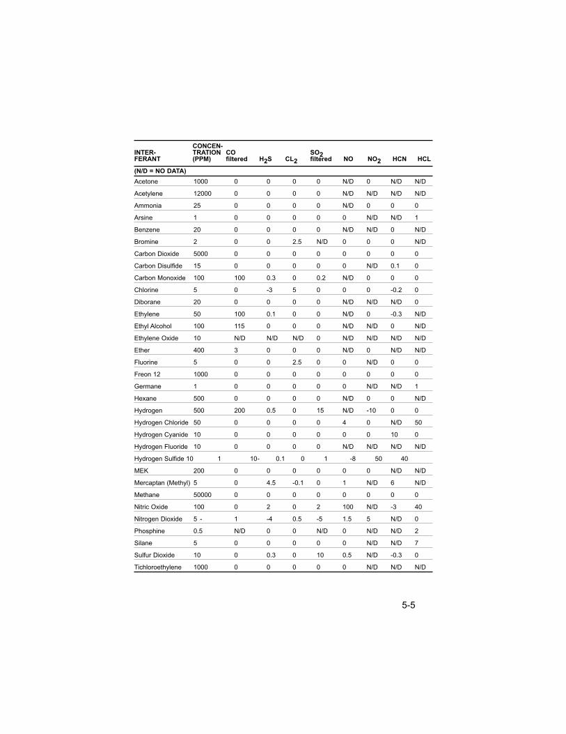
CONCEN-INTER- TRATION CO SO2FERANT (PPM) filtered H2S CL2 filtered NO NO2 HCN HCL
(N/D = NO DATA)
Acetone 1000 0 0 0 0 N/D 0 N/D N/D
Acetylene 12000 0 0 0 0 N/D N/D N/D N/D
Ammonia 25 0 0 0 0 N/D 0 0 0
Arsine 1 0 0 0 0 0 N/D N/D 1
Benzene 20 0 0 0 0 N/D N/D 0 N/D
Bromine 2 0 0 2.5 N/D 0 0 0 N/D
Carbon Dioxide 5000 0 0 0 0 0 0 0 0
Carbon Disulfide 15 0 0 0 0 0 N/D 0.1 0
Carbon Monoxide 100 100 0.3 0 0.2 N/D 0 0 0
Chlorine 5 0 -3 5 0 0 0 -0.2 0
Diborane 20 0 0 0 0 N/D N/D N/D 0
Ethylene 50 100 0.1 0 0 N/D 0 -0.3 N/D
Ethyl Alcohol 100 115 0 0 0 N/D N/D 0 N/D
Ethylene Oxide 10 N/D N/D N/D 0 N/D N/D N/D N/D
Ether 400 3 0 0 0 N/D 0 N/D N/D
Fluorine 5 0 0 2.5 0 0 N/D 0 0
Freon 12 1000 0 0 0 0 0 0 0 0
Germane 1 0 0 0 0 0 N/D N/D 1
Hexane 500 0 0 0 0 N/D 0 0 N/D
Hydrogen 500 200 0.5 0 15 N/D -10 0 0
Hydrogen Chloride 50 0 0 0 0 4 0 N/D 50
Hydrogen Cyanide 10 0 0 0 0 0 0 10 0
Hydrogen Fluoride 10 0 0 0 0 N/D N/D N/D N/D
Hydrogen Sulfide 10 1 10- 0.1 0 1 -8 50 40
MEK 200 0 0 0 0 0 0 N/D N/D
Mercaptan (Methyl) 5 0 4.5 -0.1 0 1 N/D 6 N/D
Methane 50000 0 0 0 0 0 0 0 0
Nitric Oxide 100 0 2 0 2 100 N/D -3 40
Nitrogen Dioxide 5 - 1 -4 0.5 -5 1.5 5 N/D 0
Phosphine 0.5 N/D 0 0 N/D 0 N/D N/D 2
Silane 5 0 0 0 0 0 N/D N/D 7
Sulfur Dioxide 10 0 0.3 0 10 0.5 N/D -0.3 0
Tichloroethylene 1000 0 0 0 0 0 N/D N/D N/D
5-5

CONCEN-INTER- TRATIONFERANT (PPM) CLO2 HF PH3 ASH4 SiH4 GeH3 B2H6 Br2
(N/D = NO DATA)
Acetone 1000 0 0 N/D N/D N/D N/D N/D 0
Acetylene 12000 0 0.1 N/D N/D N/D N/D 0
Ammonia 25 0 0 N/D N/D N/D N/D N/D 0
Arsine 1 0 N/D 0.7 1 1 1 5 0
Benzene 20 0 N/D N/D N/D N/D N/D N/D 0
Bromine 2 1 N/D N/D N/D N/D N/D N/D 2
Carbon Dioxide 5000 0 0 N/D N/D N/D N/D N/D 0
Carbon Disulfide 15 0 N/D 0 0 0 0 0 0
Carbon Monoxide 100 0 0 0 1 0 0 0 0
Chlorine 5 2.5 5 N/D N/D N/D N/D N/D 4
Diborane 20 0 N/D 3.5 5 4 5 20 0
Ethylene 50 0 0 0.5 1 1 1 2 0
Ethyl Alcohol 100 0 0 N/D N/D N/D N/D N/D 0
Ethylene Oxide 10 0 N/D N/D N/D N/D N/D N/D N/D
Ether 400 0 0 N/D N/D N/D N/D N/D 0
Fluorine 5 1 N/D N/D N/D N/D N/D N/D 2
Freon 12 1000 0 0 0 0 0 0 0 0
Germane 1 0 N/D 0.7 1 1 1 5 0
Hexane 500 0 0 N/D N/D N/D N/D N/D 0
Hydrogen 500 0 0 0 0 0 0 0 0
Hydrogen Chloride 50 0 30 N/D N/D N/D N/D N/D 0
Hydrogen Cyanide 10 0 0 N/D N/D N/D N/D N/D 0
Hydrogen Fluoride 10 0 10 N/D N/D N/D N/D N/D 0
Hydrogen Sulfide 10 0 3 N/D N/D N/D N/D N/D 0
MEK 200 0 N/D N/D N/D N/D N/D N/D 0
Mercaptan (Methyl) 5 0 N/D N/D N/D N/D N/D N/D 0
Methane 5000 0 0 N/D N/D N/D N/D N/D 0
Nitric Oxide 100 0 2 N/D N/D N/D N/D N/D 0
Nitrogen Dioxide 5 0.2 2.5 N/D N/D N/D 0.5 N/D 0.4
Phosphine 0.5 0 0 0.5 1 0.7 1 3 0
Silane 5 0 N/D 0.1 0.2 5 0.2 15 0
Sulfur Dioxide 10 0 8 0.5 1 2 3 6 0
Tichloroethylene 1000 0 0 N/D N/D N/D N/D N/D 0
5-6

CONCEN-INTER- TRATIONFERANT (PPM) F2 NH3 H2 EtO
Acetone 1000 0 N/D N/D N/D
Acetylene 12000 0 N/D N/D N/D
Ammonia 25 0 25 N/D 0
Arsine 1 0 N/D N/D N/D
Benzene 20 0 N/D N/D N/D
Bromine 2 12 N/D N/D N/D
Carbon Dioxide 5000 0 0 0 N/D
Carbon Disulfide 15 0 N/D N/D N/D
Carbon Monoxide 100 0 0 2 N/D
Chlorine 5 10 0 0 0
Diborane 20 0 N/D N/D N/D
Ethylene 50 0 0 40 N/D
Ethyl Alcohol 100 0 N/D N/D 10
Ethylene Oxide 10 N/D N/D N/D 10
Ether 400 0 N/D N/D N/D
Fluorine 5 5 N/D N/D N/D
Freon 12 1000 0 0 0 0
Germane 1 0 N/D N/D N/D
Hexane 500 0 N/D N/D N/D
Hydrogen 500 0 N/D 500 N/D
Hydrogen Chloride 50 0 0 0 N/D
Hydrogen Cyanide 10 0 0 3 0
Hydrogen Fluoride 10 0 N/D N/D N/D
Hydrogen Sulfide 10 -0.2 0.5 1 N/D
MEK 200 0 0 N/D 3
Mercaptan (Methyl) 5 - 0.2 N/D N/D N/D
Methane 5000 0 N/D N/D N/D
Nitric Oxide 100 0 0 3 N/D
Nitrogen Dioxide 5 1 N/D N/D 0
Phosphine 0.5 0 0 0 0
Silane 5 0 N/D N/D N/D
Sulfur Dioxide 10 0 0 0 N/D
Tichloroethylene 1000 0 N/D N/D N/D
5-7

Chapter 6, Maintenance
General
The Trigard Gas Monitor is constantly performing a self-check. When aproblem is found, it displays the appropriate error message. (Table 6-3,"Troubleshooting Guidelines"). When a critical error is detected withinthe unit, the output signal goes to a fault condition.
• For 4 to 20 milliamp output models: the fault output is 3.0 mA
• The "Change Sensor" indication is not an error and does not affectthe output.
NOTE: TABLES 6-1 and 6-2 describe the messages that usersmay see.
Replacing Trigard Sensor
The only routine maintenance item is the sensing element itself, whichhas a limited lifetime. When the Trigard Gas Monitor’s read-outindicates that the sensor must be changed, there is very little sensorlifetime remaining. It is good practice to obtain a replacement sensingelement before the sensing element within your unit becomesinoperative. Typically, the Trigard Monitor LCD display shows amaintenance message when the sensor is due for replacement(FIGURE 6-1).
1).
Figure 6-1. "Change Sensor" Scrolls Across the Display
6-1

Handle the sensor carefully; the electrochemical version is asealed unit which contains a corrosive electrolyte. If elec-trolyte is leaking from the sensor, exercise CAUTION toensure the electrolyte does not contact skin, eyes or cloth-ing, thus avoiding burns. If contact occurs, rinse the areaimmediately with a large quantity of water. In case of contactwith eyes, immediately flush eyes with plenty of water for atleast 15 minutes. Call a physician.
Do not install a leaking sensor in the sensing head assem-bly. The leaking sensor must be disposed of in accordancewith local, state and federal laws. To obtain a replacementsensor, contact MSA at the address given under "ObtainingReplacement Parts."
1. There is no need to open the main enclosure; simply unscrew thesensor assembly located on the bottom of the Trigard Gas Monitormain assembly (FIGURE 6-2).
1).
2. Identify the sensor assembly needed and obtain the appropriatesensor assembly; replace sensor assembly.
NOTE: Alarm setpoints and relay functions (energized/de-energized, latching/unlatching, and upscale/downscale) willnot change when changing a sensor module from itscurrent gas type to the same gas type (e.g., carbonmonoxide to carbon monoxide). Alarm setpoints and theupscale/downscale relay function will change to the newsensor’s default settings when changing a sensor modulefrom its current gas type to a different gas type (e.g.,carbon monoxide to oxygen).
" CAUTION
Figure 6-2. Sensor Assembly and Sensor Guard for General Purpose Model
" WARNING
6-2

3. The Trigard Gas Monitor is shipped with the Sensor Swap Delayenabled. This means that the 4-20 mA output signal and theFAULT relay will hold off a fault indication for 60 seconds after thesensor missing indication is displayed on the instrument. Thissetting allows the operator to exchange sensor modules without aFAULT indication.
4. Refer to Chapter 3, "Calibration".
It is recommended that all other maintenance be performed at an MSAfactory-authorized service center.
Table 6-1. Operational Display Messages
MESSAGE INDICATES
MM/DD/YY Format for date scrolling
VER Software version level will display next
TIME Time will display next
DATE Date will display next
MIN MIN value for this interval will display next
MAX MAX value for this interval will display next
AVG AVG value for this interval will display next
Adr Instrument’s address will display next
End End of calibration cycle
Err An Error code will display next
HR Special case indicates hours (two characters or less)
OVER Gas value is greater than the set range
6-3
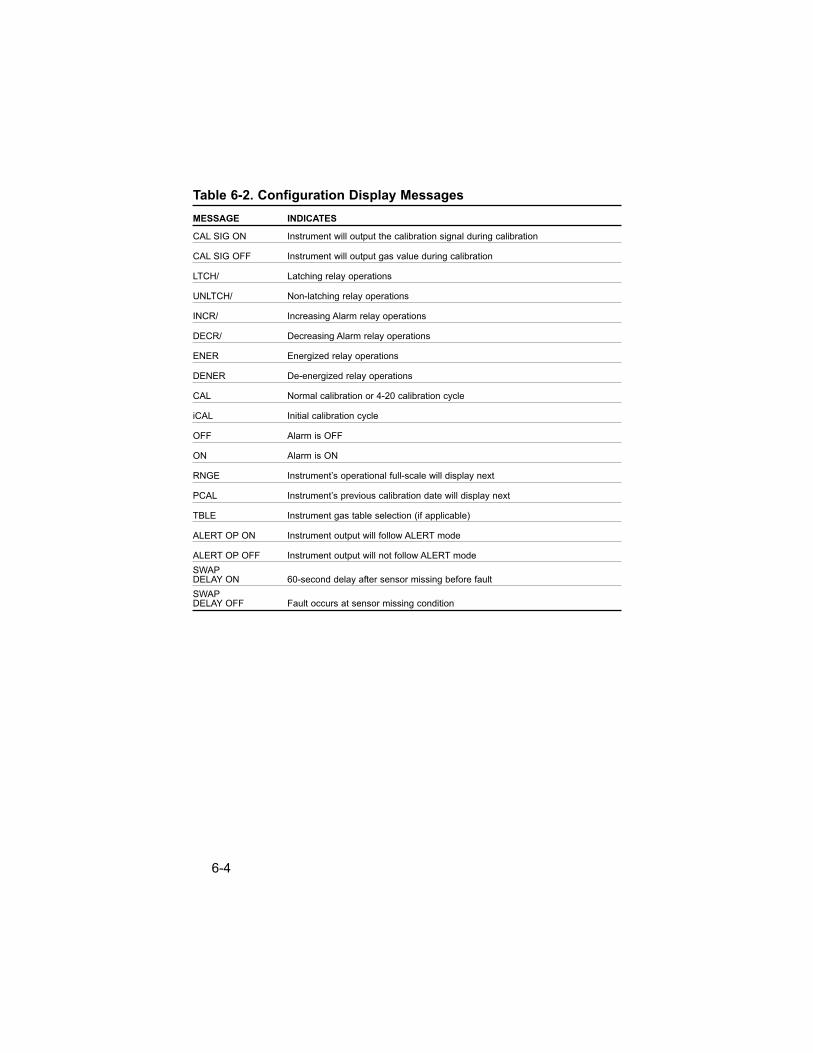
Table 6-2. Configuration Display Messages
MESSAGE INDICATES
CAL SIG ON Instrument will output the calibration signal during calibration
CAL SIG OFF Instrument will output gas value during calibration
LTCH/ Latching relay operations
UNLTCH/ Non-latching relay operations
INCR/ Increasing Alarm relay operations
DECR/ Decreasing Alarm relay operations
ENER Energized relay operations
DENER De-energized relay operations
CAL Normal calibration or 4-20 calibration cycle
iCAL Initial calibration cycle
OFF Alarm is OFF
ON Alarm is ON
RNGE Instrument’s operational full-scale will display next
PCAL Instrument’s previous calibration date will display next
TBLE Instrument gas table selection (if applicable)
ALERT OP ON Instrument output will follow ALERT mode
ALERT OP OFF Instrument output will not follow ALERT mode
SWAPDELAY ON 60-second delay after sensor missing before fault
SWAPDELAY OFF Fault occurs at sensor missing condition
6-4

Table 6-3. Troubleshooting Guidelines
MESSAGE INDICATES ACTION
CHANGE SENSOR Sensor is at its end of life Replace sensor
CAL FAULT Instrument did not calibratesuccessfully Repeat calibration; check
for proper calibration gas;check for blockage in the flow system
SENSOR MISSING Instrument has lost communication with the sensor module Connect or replace sensor
CHECK CAL Calibration should be verified Perform bump test or calibration
SENSOR WARNING Sensor is approaching end of life Prepare to replace sensor module
SNSR FLASH FAULT Sensor module program memory is invalid Replace sensor module
SNSR RAM FAULT Sensor module has adefective RAM location Replace sensor module
SNSR DATA FAULT Sensor module datasheet invalid Send reset data sheet command from the controller; if error persists,replace sensor
MN SUPPLY FAULT Power supply on main PCBA is out of range Check sensor wiring or
replace main pc board
MN EEPROM FAULT EEPROM on main PCBA is invalid Replace main pc board
MN FLASH FAULT Program memory on the main PCBA is invalid Replace main pc board
MN RAM FAULT Defective RAM memory location was found on the main PCBA Replace main pc board
INVALID SENSOR Attached sensor module is notcompatible with main instrument Replace with correct sensor type
CONFIG RESET Main EEPROM memory was reset Use Controller to reset allconfigurations (e.g., alarm levels,calibration signals ON or OFF, etc)
RELAY FAULT Error with the internalrelays has occurred Cycle power to the unit or replace main
pc board
SNSR POWER FAULT Power at the sensor module is out of range Correct wiring error, replace main pc
board, or replace sensor module
und Under-range condition - quick Recalibrate or replace sensor
Und Under-range condition - slow Recalibrate or replace sensor
+LOC Instrument is locked inover-range condition Recalibrate or reset sensor
IR SOURCE FAULT IR source failure Replace or consult factory
REF SIG FAULT IR reference detector failure Replace or consult factory
ANA SIG FAULT IR analytical detector failure Replace or consult factory
LOW SIGNAL Low IR signal Clean optics or replace sensor module
- SUPPLY FAULT The negative supply sensor module is out of range Check wiring or replace sensor module
PARAM FAULT An operational parameter is out of range or sensor failed internal check Restart; replace, if necessary
6-5

Obtaining Replacement Parts
See TABLE 6-4 for replacement sensor kits. To obtain a replacementsensor, address the order or inquiry to:
Mine Safety Appliances Company1000 Cranberry Woods Drive, Cranberry Township PA 16066
or call, toll-free, 1-800-MSA-INST.
Use only genuine MSA replacement parts when performingany maintenance procedures provided in this manual.Failure to do so may seriously impair sensor performance.Repair or alteration of the Trigard Gas Monitor, beyond thescope of these maintenance instructions or by anyone otherthan authorized MSA service personnel, could cause theproduct to fail to perform as designed and persons who relyon this product for their safety could sustain serious per-sonal injury or death.
Table 6-4. Replacement Parts
GAS SELECTION SENSOR KIT PART NO.
GENERAL-PURPOSEMODELS
Carbon Monoxide, 100 ppm A-ULTX-SENS-11-0...
Carbon Monoxide, 500 ppm A-ULTX-SENS-12-0...
Oxygen, 10% - compensated A-ULTX-SENS-13-0...
Oxygen, 25% - compensated A-ULTX-SENS-14-0...
Hydrogen Sulfide, 10 ppm A-ULTX-SENS-15-0...
Hydrogen Sulfide, 50 ppm A-ULTX-SENS-16-0...
Hydrogen Sulfide, 100 ppm A-ULTX-SENS-17-0...
Chlorine, 5 ppm A-ULTX-SENS-18-0...
Sulfur Dioxide, 25 ppm A-ULTX-SENS-70-0...
Sulfur Dioxide, 100 ppm A-ULTX-SENS-71-0...
Nitric Oxide, 100 ppm A-ULTX-SENS-20-0...
Nitrogen Dioxide, 10 ppm A-ULTX-SENS-72-0...
Hydrogen Cyanide, 50 ppm A-ULTX-SENS-22-0...
Hydrogen Chloride, 50 ppm A-ULTX-SENS-23-0...
Chlorine Dioxide, 3 ppm A-ULTX-SENS-24-0...
Combustible Gas, 100% LELNatural Gas and H2, 5% CH4 A-ULTX-SENS-31-0...
Combustible Gas, 100% LELPetroleum Vapors, 2.1 % Propane A-ULTX-SENS-32-0...
Combustible Gas, 100% LELSolvents, 2.1% Propane A-ULTX-SENS-33-0...
" WARNING
6-6

Comb Gas IR - Methane, 5% CH4 not available
Comb Gas IR - Non Methane,2.1 % Propane not available
Phosphine, 2 ppm A-ULTX-SENS-41-0...
Arsine, 2 ppm A-ULTX-SENS-42-0...
Silane, 25 ppm A-ULTX-SENS-43-0...
Diborane, 50 ppm A-ULTX-SENS-45-0...
Bromine, 5 ppm A-ULTX-SENS-46-0...
Fluorine, 5 ppm A-ULTX-SENS-47-0...
Ammonia, 50 ppm A-ULTX-SENS-48-0...
Hydrogen, 1000 ppm A-ULTX-SENS-49-0...
ETO, 10 ppm A-ULTX-SENS-50-0...
SENSOR GUARD REPLACEMENT PARTS
All Sensor Types 10028904
STROBES
Red 634674
Amber 655629
BACKUP BATTERY 10098441
PCBA SELECTION
3-Wire, 4-20 mA 10100992
ModBUS 10100991
6-7
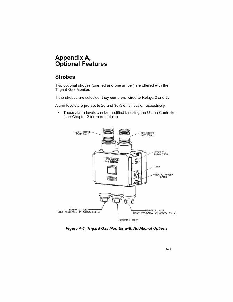
Appendix A, Optional Features
Strobes
Two optional strobes (one red and one amber) are offered with theTrigard Gas Monitor.
If the strobes are selected, they come pre-wired to Relays 2 and 3.
Alarm levels are pre-set to 20 and 30% of full scale, respectively.
• These alarm levels can be modified by using the Ultima Controller(see Chapter 2 for more details).
1).
Figure A-1. Trigard Gas Monitor with Additional Options
A-1
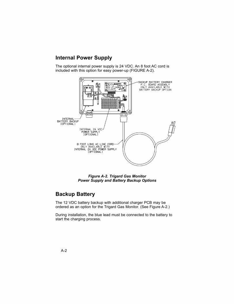
Internal Power Supply
The optional internal power supply is 24 VDC. An 8 foot AC cord isincluded with this option for easy power-up (FIGURE A-2).
1).
Backup Battery
The 12 VDC battery backup with additional charger PCB may beordered as an option for the Trigard Gas Monitor. (See Figure A-2.)
During installation, the blue lead must be connected to the battery tostart the charging process.
Figure A-2. Trigard Gas Monitor Power Supply and Battery Backup Options
A-2