Embed Size (px)
Citation preview

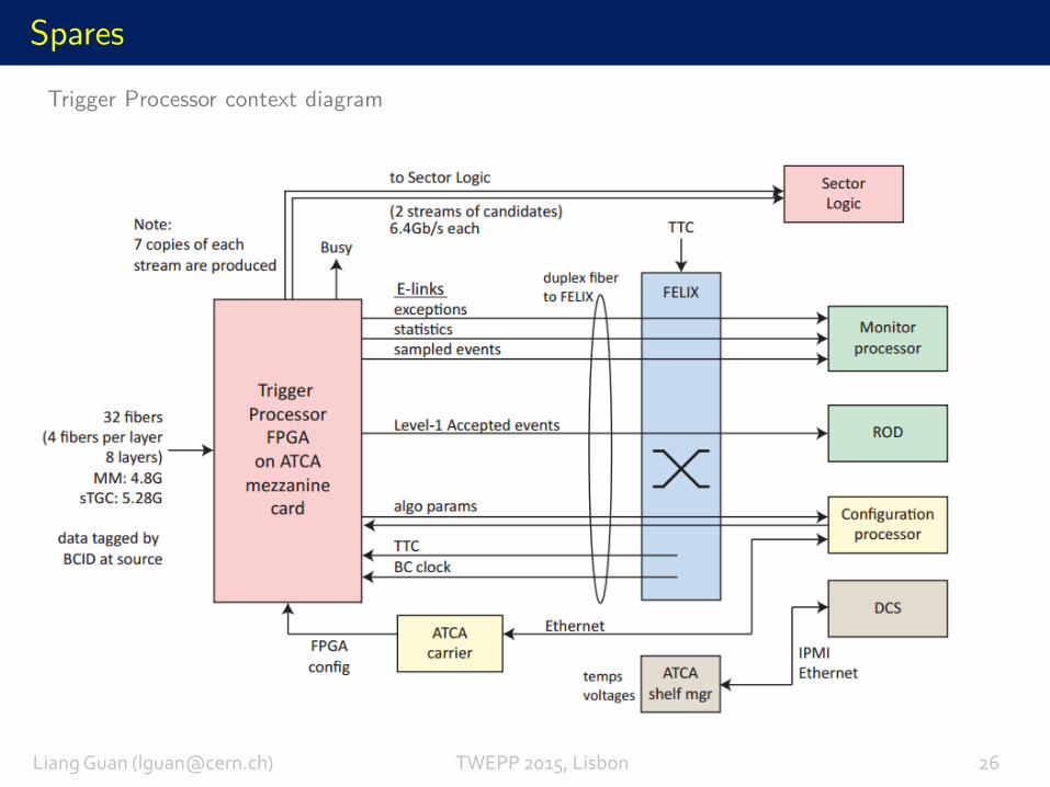
Trigger Algorithms and Electronics for the
ATLAS Muon NSW Upgrade
Topical Workshop on Electronics for Particle Physics29, September, 2015, Lisbon
University of Michigan
Liang Guan
on behalf of the ATLAS Muon Collaboration
Outline
Introduction: ATLAS Muon NSW Upgrade
Part I: NSW Trigger Processors and Trigger Algorithms
Part II: NSW Trigger Front-end Electronics
Conclusions and Outlook
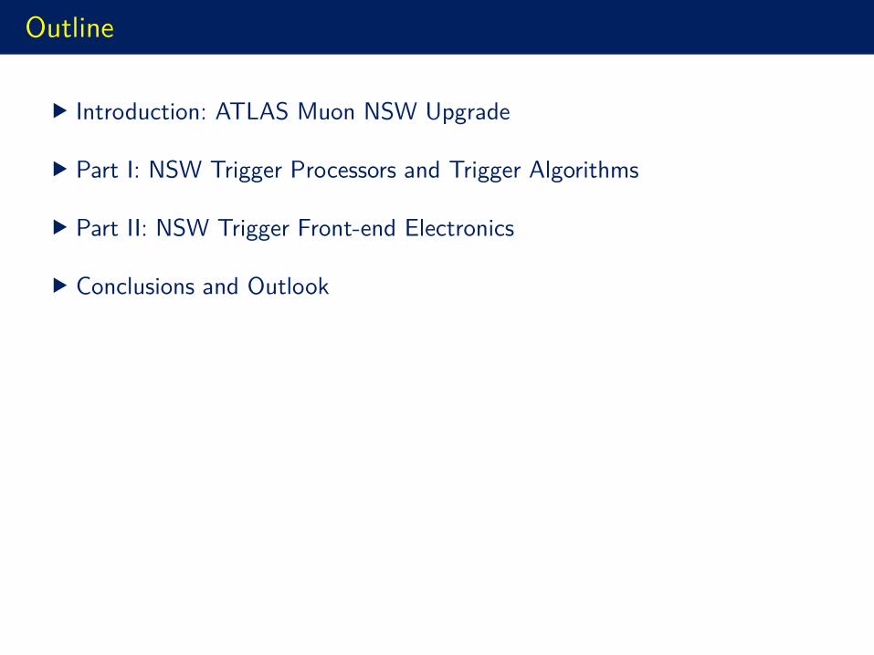
Introduction – LHC and ATLAS upgrade schedule
Liang Guan ([email protected]) TWEPP 2015, Lisbon 01
• Phase-0: Insertable B-Layer (IBL) in LS1
• Phase-1: Muon New Small Wheels, Calorimeter trigger, Fast Tracker
• Phase-2: New Inner Tracker, New Trigger architecture, Muon Spectrometer …
ATLAS Main Upgrades
Muon Detector Solenoid
LAr Calorimeter
Inner Tracker
Toroid Magnet
We Are Here!
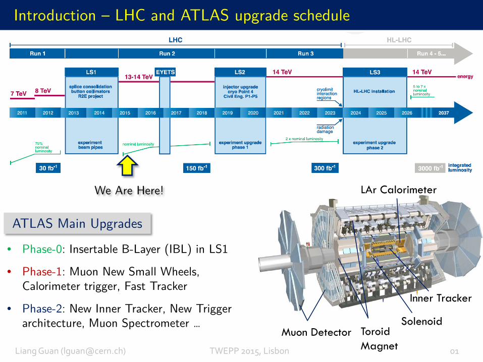
Introduction – ATLAS Muon NSW Upgrade
Liang Guan ([email protected]) TWEPP 2015, Lisbon 02
RUN-1 ATLAS Level-1(LV1) Muon Trigger in the End-cap Region only relies on segment measurements at the Big Wheel using Thin Gap Chambers
Small Wheel(SW)
Big Wheel (BW)
RUN-1η Distribution of LV1 muon (pT>10 GeV)
50 ns Bunch Spacing
End-capEnd-cap
Triggered L1 RoI
Matched with off-line (pT>10 GeV)
Trigger rate dominated by the End-cap due to backgrounds: “fake” and real muons indistinguishable at high luminosity
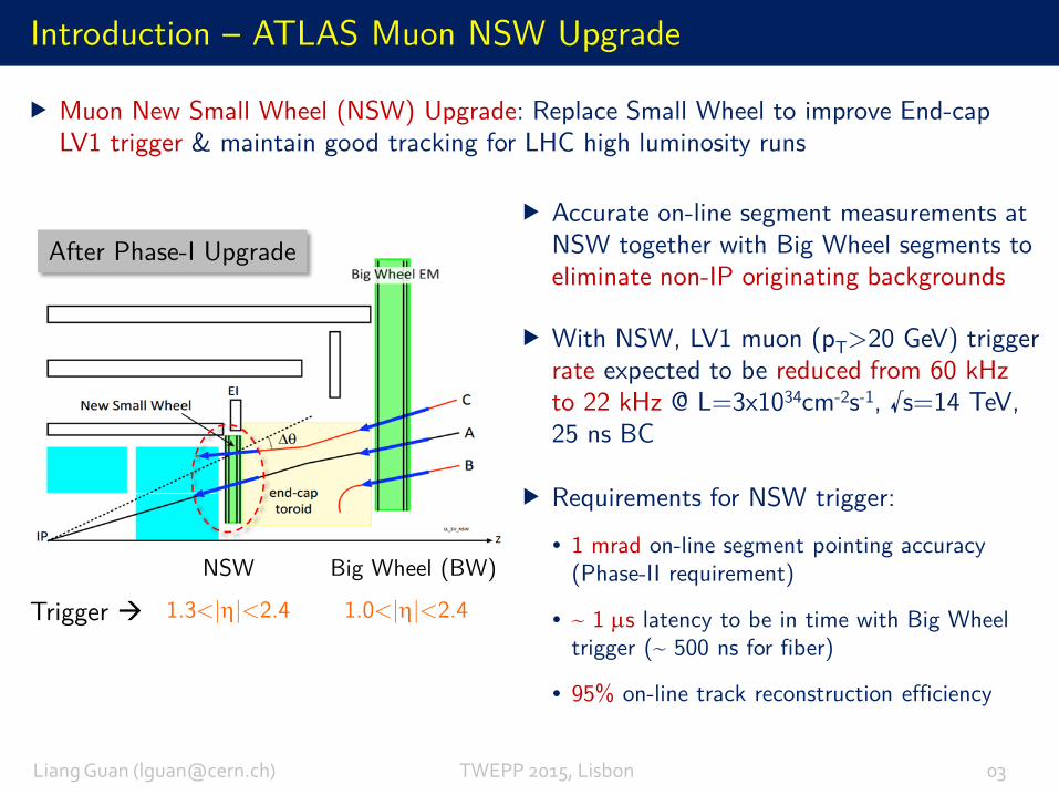
Muon New Small Wheel (NSW) Upgrade: Replace Small Wheel to improve End-cap LV1 trigger & maintain good tracking for LHC high luminosity runs
Introduction – ATLAS Muon NSW Upgrade
Liang Guan ([email protected]) TWEPP 2015, Lisbon 03
1.0<|η|<2.41.3<|η|<2.4
Big Wheel (BW)NSW
Trigger
Accurate on-line segment measurements at NSW together with Big Wheel segments to eliminate non-IP originating backgrounds
After Phase-I Upgrade
Requirements for NSW trigger:
• 1 mrad on-line segment pointing accuracy (Phase-II requirement)
• ~ 1 µs latency to be in time with Big Wheel trigger (~ 500 ns for fiber)
• 95% on-line track reconstruction efficiency
With NSW, LV1 muon (pT>20 GeV) trigger rate expected to be reduced from 60 kHz to 22 kHz @ L=3x1034cm-2s-1, √s=14 TeV, 25 ns BC
Introduction – ATLAS Muon NSW Upgrade
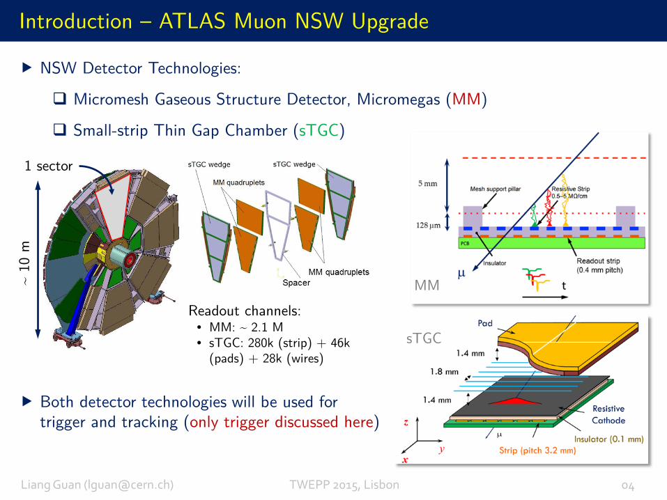
Both detector technologies will be used for trigger and tracking (only trigger discussed here)
MM
sTGC
~ 10
m
NSW Detector Technologies:
Micromesh Gaseous Structure Detector, Micromegas (MM)
Small-strip Thin Gap Chamber (sTGC)
Readout channels: • MM: ~ 2.1 M• sTGC: 280k (strip) + 46k
(pads) + 28k (wires)
1 sector
Liang Guan ([email protected]) TWEPP 2015, Lisbon 04
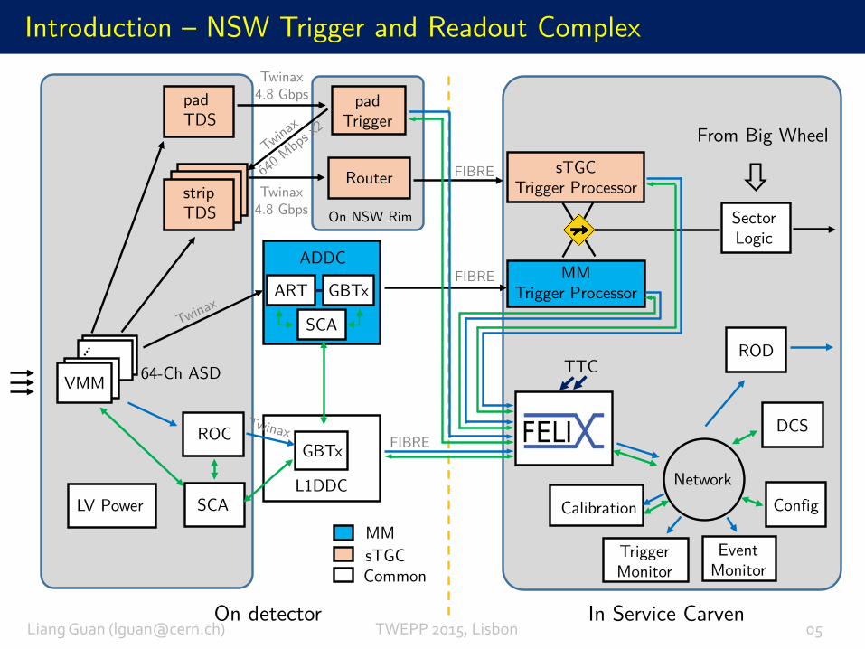
Introduction – NSW Trigger and Readout Complex
In Service Carven
padTDS
padTrigger
Router sTGCTrigger Processor
MMTrigger Processor
ROC
stripTDS
VMM
SCALV PowerNetwork
ROD
Calibration
EventMonitor
Config
DCS
Trigger Monitor
L1DDC
GBTx
SectorLogic
TTC
FIBRE
FIBRE
FIBRE
Twinax4.8 Gbps
Twinax4.8 Gbps
ADDC
ART GBTx
SCA
From Big Wheel
On detector
On NSW Rim
MMsTGCCommon
64-Ch ASD
Liang Guan ([email protected]) TWEPP 2015, Lisbon 05
Part I: NSW Trigger Processors and Trigger Algorithms
NSW Trigger Primitives Raw Information
Liang Guan ([email protected]) TWEPP 2015, Lisbon 06
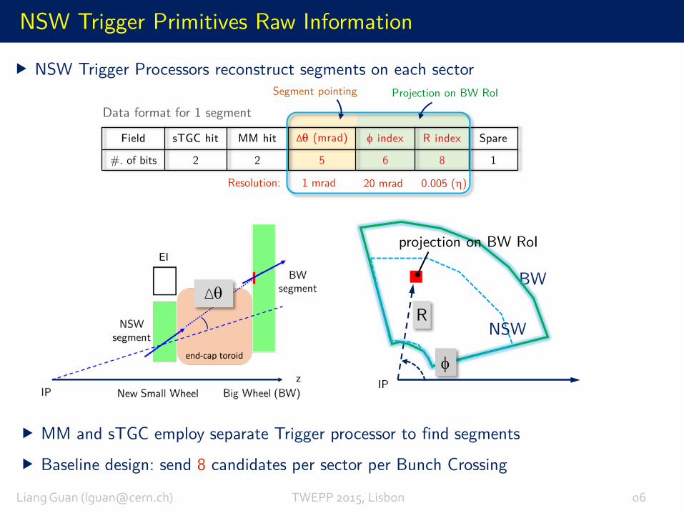
NSW Trigger Processors reconstruct segments on each sector
Field sTGC hit MM hit ∆θ (mrad) φ index R index Spare
#. of bits 2 2 5 6 8 1
Resolution: 1 mrad 20 mrad 0.005 (η)
Data format for 1 segmentProjection on BW RoISegment pointing
Baseline design: send 8 candidates per sector per Bunch Crossing
MM and sTGC employ separate Trigger processor to find segments
∆θR
IP
BW
NSW
projection on BW RoI
φ
sTGC Trigger Algorithm
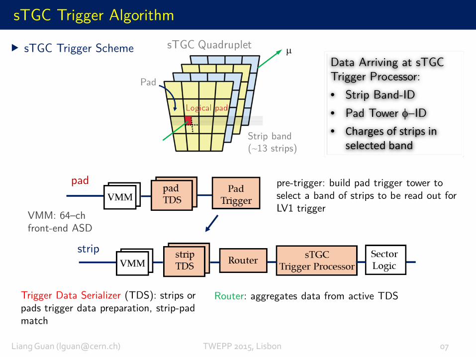
pre-trigger: build pad trigger tower to select a band of strips to be read out for LV1 trigger
Trigger Data Serializer (TDS): strips or pads trigger data preparation, strip-pad match
Router: aggregates data from active TDS
Data Arriving at sTGC Trigger Processor:• Strip Band-ID• Pad Tower φ−ID• Charges of strips in
selected band
Liang Guan ([email protected]) TWEPP 2015, Lisbon 07
sTGC Trigger Scheme
VMM: 64–chfront-end ASD
strip
pad
sTGC Trigger Algorithm
Liang Guan ([email protected]) TWEPP 2015, Lisbon 08IP
zr
sTGC Pivot
Quadruplet
sTGC ConfirmationQuadruplet
MM
pad strip
Charge cluster
RA
Big Wheel
∆θ
θ
End-
cap
Toro
id
(not
to s
cale)
R-index
RB
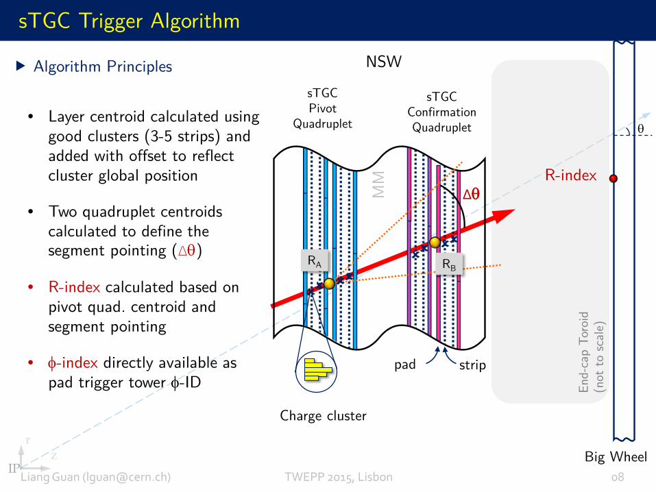
Algorithm Principles
• Layer centroid calculated using good clusters (3-5 strips) and added with offset to reflect cluster global position
• Two quadruplet centroids calculated to define the segment pointing (∆θ)
• R-index calculated based on pivot quad. centroid and segment pointing
• φ-index directly available as pad trigger tower φ-ID
NSW
Liang Guan ([email protected]) TWEPP 2015, Lisbon 09
MM Trigger Algorithms
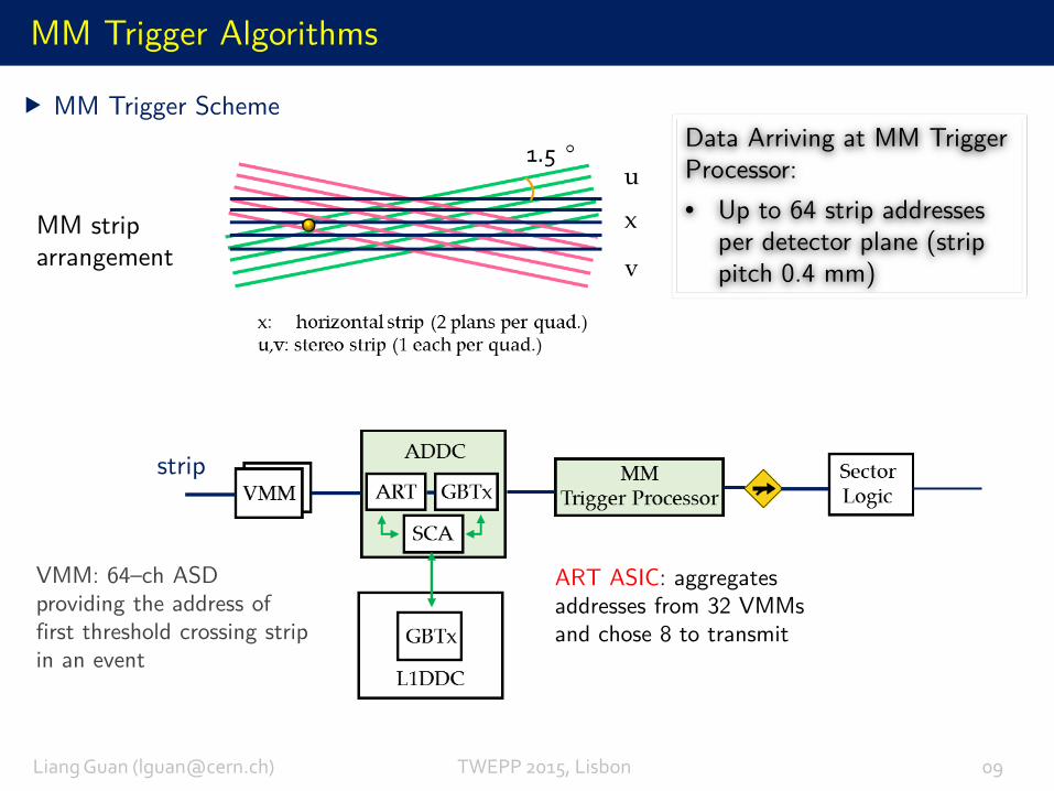
MM Trigger Scheme
ART ASIC: aggregates addresses from 32 VMMs and chose 8 to transmit
Data Arriving at MM Trigger Processor:• Up to 64 strip addresses
per detector plane (strip pitch 0.4 mm)
VMM: 64–ch ASD providing the address of first threshold crossing stripin an event
strip
MM strip arrangement
Liang Guan ([email protected]) TWEPP 2015, Lisbon 10
MM Trigger Algorithms (Con’t)
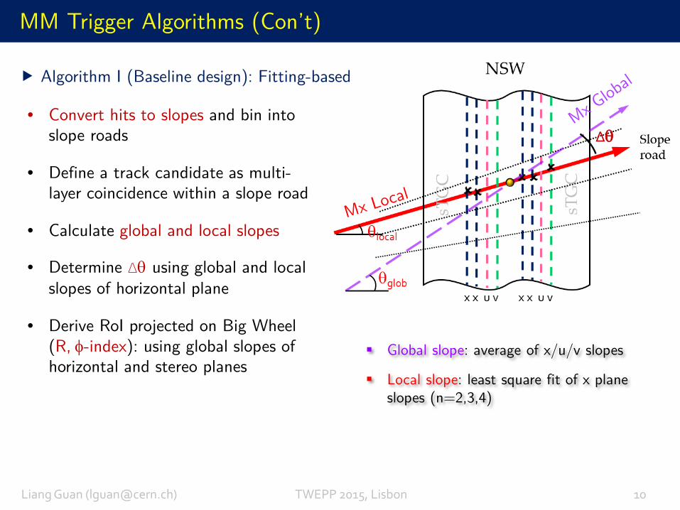
Global slope: average of x/u/v slopes
Local slope: least square fit of x plane slopes (n=2,3,4)
Algorithm I (Baseline design): Fitting-based
• Convert hits to slopes and bin into slope roads
• Define a track candidate as multi-layer coincidence within a slope road
• Calculate global and local slopes
• Determine ∆θ using global and local slopes of horizontal plane
• Derive RoI projected on Big Wheel (R, φ-index): using global slopes of horizontal and stereo planes
∆θ
MM Trigger Algorithms (Con’t)
Liang Guan ([email protected]) TWEPP 2015, Lisbon 11
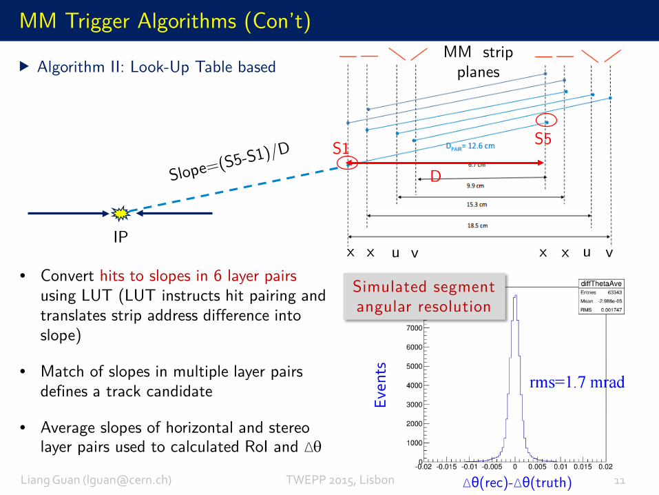
Algorithm II: Look-Up Table based
∆θ(rec)-∆θ(truth)
• Convert hits to slopes in 6 layer pairsusing LUT (LUT instructs hit pairing and translates strip address difference into slope)
• Match of slopes in multiple layer pairs defines a track candidate
• Average slopes of horizontal and stereo layer pairs used to calculated RoI and ∆θ
x u vx x u vxIP
DS1 S5
Simulated segment angular resolution
MM strip planes
Even
ts
Trigger Processor Hardware Platform
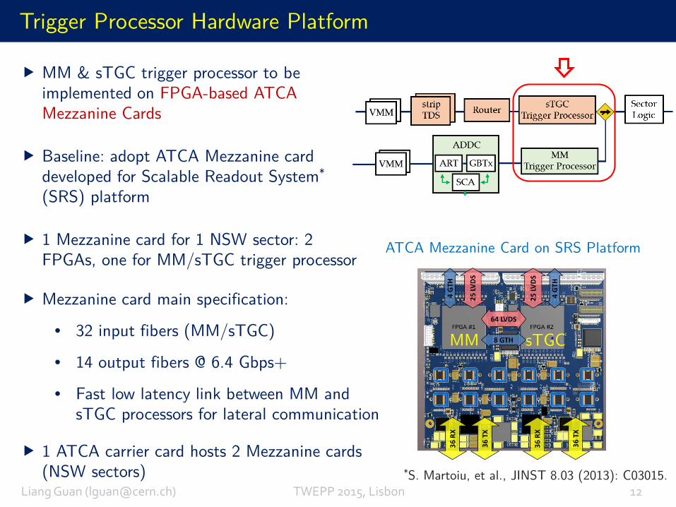
MM & sTGC trigger processor to be implemented on FPGA-based ATCA Mezzanine Cards
Baseline: adopt ATCA Mezzanine card developed for Scalable Readout System*
(SRS) platform
1 Mezzanine card for 1 NSW sector: 2 FPGAs, one for MM/sTGC trigger processor
ATCA Mezzanine Card on SRS Platform
Liang Guan ([email protected]) TWEPP 2015, Lisbon 12
*S. Martoiu, et al., JINST 8.03 (2013): C03015.
MM sTGC
Mezzanine card main specification:
• 32 input fibers (MM/sTGC)
• 14 output fibers @ 6.4 Gbps+
• Fast low latency link between MM and sTGC processors for lateral communication
1 ATCA carrier card hosts 2 Mezzanine cards (NSW sectors)
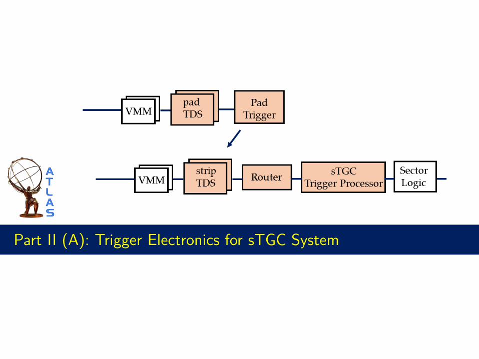
Part II (A): Trigger Electronics for sTGC System
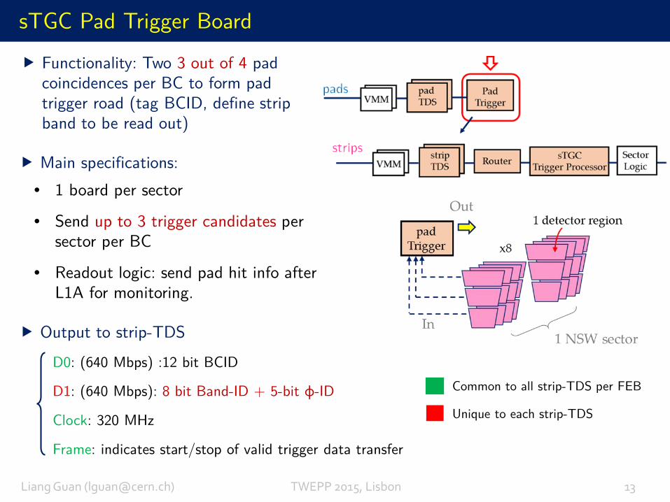
sTGC Pad Trigger Board
Main specifications:• 1 board per sector
• Send up to 3 trigger candidates per sector per BC
• Readout logic: send pad hit info after L1A for monitoring.
Functionality: Two 3 out of 4 pad coincidences per BC to form pad trigger road (tag BCID, define strip band to be read out)
Liang Guan ([email protected]) TWEPP 2015, Lisbon 13
Output to strip-TDS
D0: (640 Mbps) :12 bit BCID
D1: (640 Mbps): 8 bit Band-ID + 5-bit φ-ID
Clock: 320 MHz
Frame: indicates start/stop of valid trigger data transfer
Common to all strip-TDS per FEB
Unique to each strip-TDS
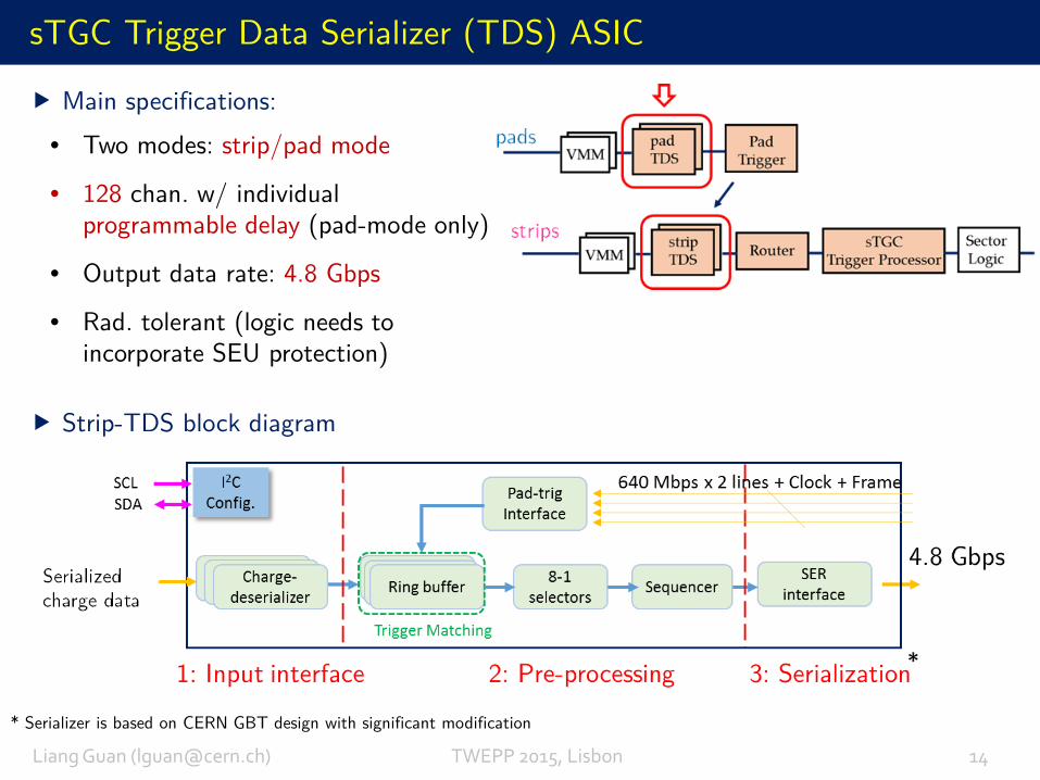
Main specifications:• Two modes: strip/pad mode
• 128 chan. w/ individual programmable delay (pad-mode only)
• Output data rate: 4.8 Gbps
• Rad. tolerant (logic needs to incorporate SEU protection)
sTGC Trigger Data Serializer (TDS) ASIC
Liang Guan ([email protected]) TWEPP 2015, Lisbon 14
* Serializer is based on CERN GBT design with significant modification
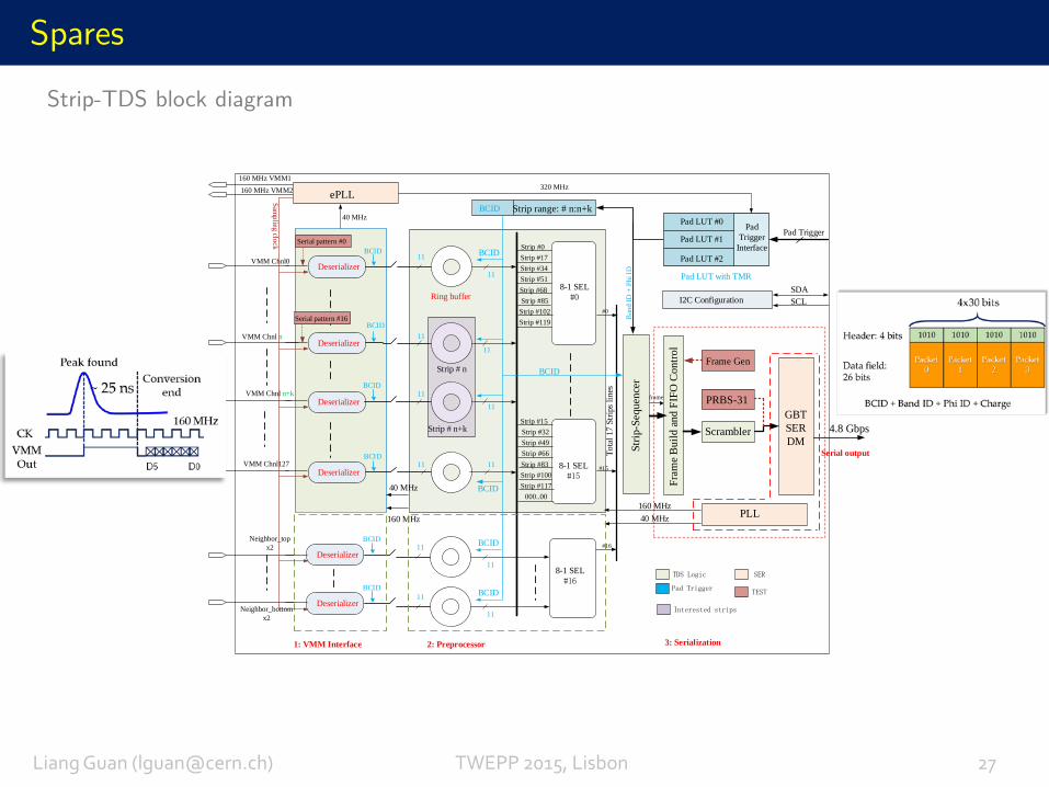
Strip-TDS block diagram
sTGC Trigger Data Serializer (TDS) ASIC
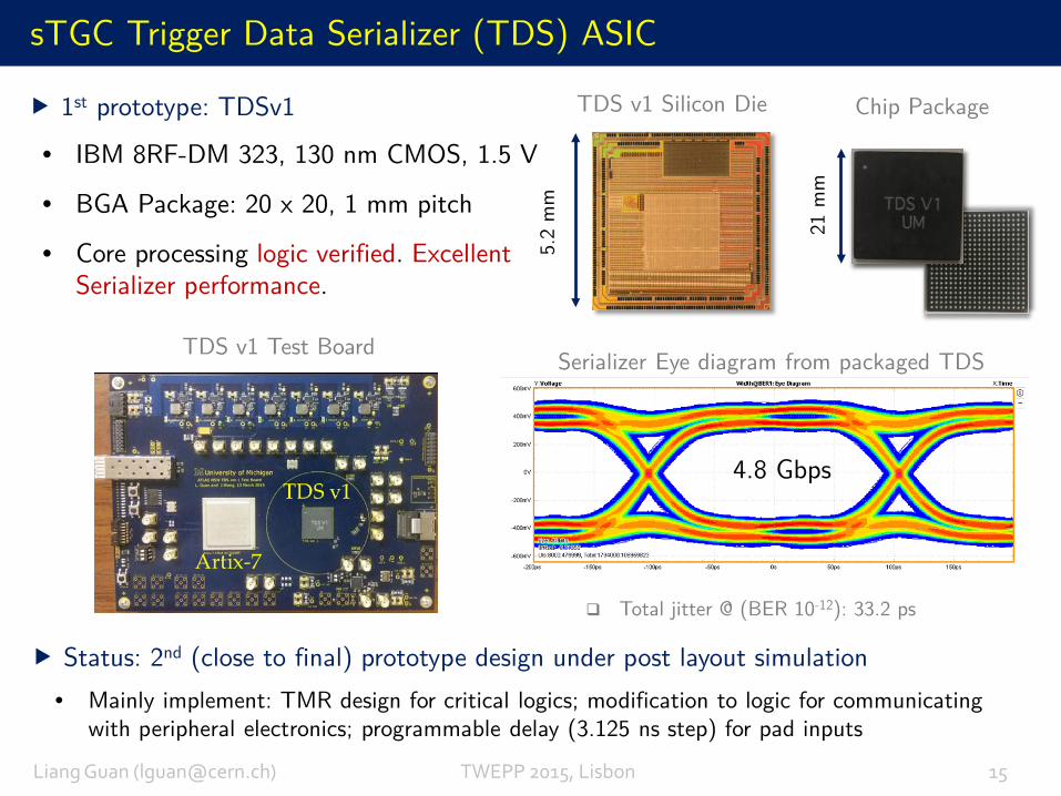
Total jitter @ (BER 10-12): 33.2 ps
• IBM 8RF-DM 323, 130 nm CMOS, 1.5 V
• BGA Package: 20 x 20, 1 mm pitch
• Core processing logic verified. Excellent Serializer performance.
Serializer Eye diagram from packaged TDS
TDS v1 Silicon Die
4.8 Gbps
1st prototype: TDSv1 Chip Package
5.2
mm
21 m
m
TDS v1 Test Board
Status: 2nd (close to final) prototype design under post layout simulation• Mainly implement: TMR design for critical logics; modification to logic for communicating
with peripheral electronics; programmable delay (3.125 ns step) for pad inputs
Liang Guan ([email protected]) TWEPP 2015, Lisbon 15
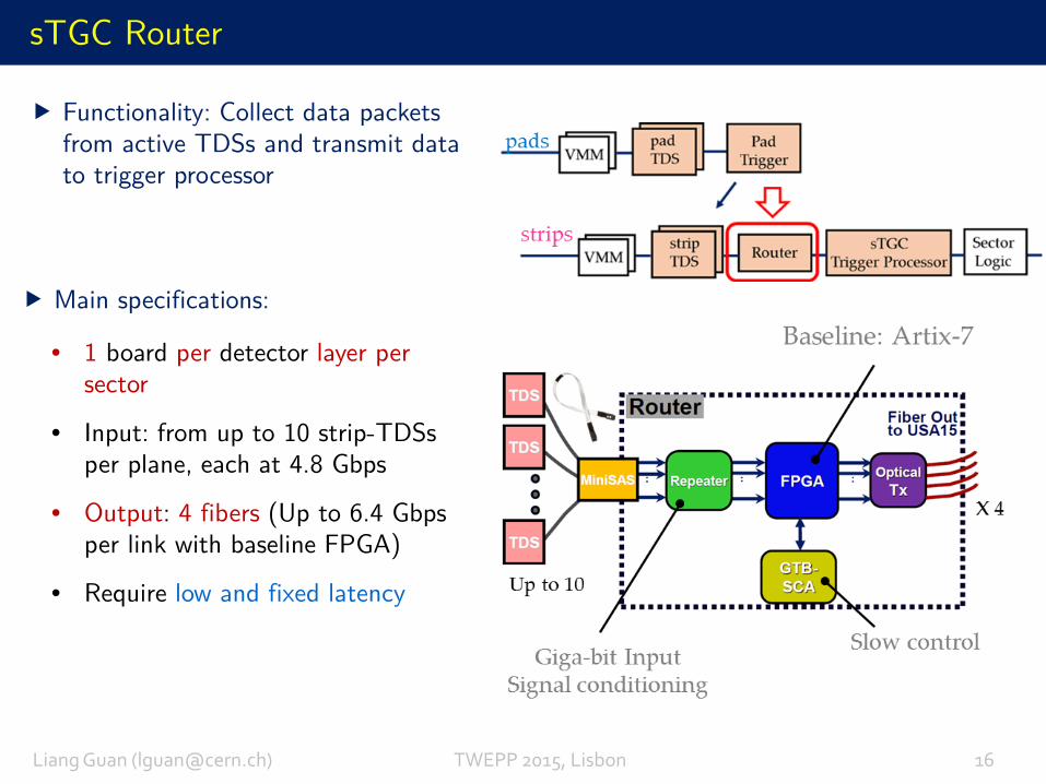
sTGC Router
Main specifications:
• 1 board per detector layer per sector
• Input: from up to 10 strip-TDSs per plane, each at 4.8 Gbps
• Output: 4 fibers (Up to 6.4 Gbpsper link with baseline FPGA)
• Require low and fixed latency
Liang Guan ([email protected]) TWEPP 2015, Lisbon 16
Functionality: Collect data packets from active TDSs and transmit data to trigger processor
sTGC Router
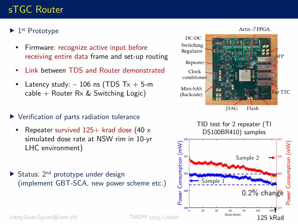
1st Prototype
Verification of parts radiation tolerance
• Repeater survived 125+ krad dose (40 x simulated dose rate at NSW rim in 10-yr LHC environment)
Status: 2nd prototype under design (implement GBT-SCA, new power scheme etc.)
• Firmware: recognize active input before receiving entire data frame and set-up routing
• Link between TDS and Router demonstrated
• Latency study: ~ 106 ns (TDS Tx + 5-m cable + Router Rx & Switching Logic)
Liang Guan ([email protected]) TWEPP 2015, Lisbon 17
TID test for 2 repeater (TI DS100BR410) samples
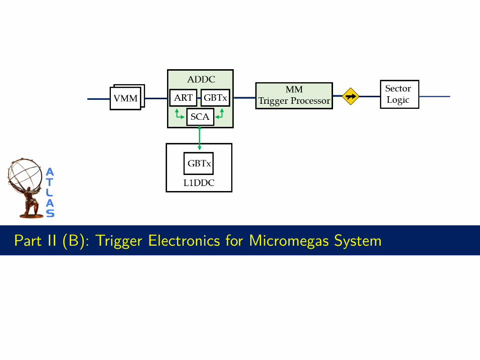
Part II (B): Trigger Electronics for Micromegas System
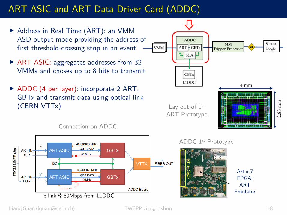
ART ASIC and ART Data Driver Card (ADDC)
Connection on ADDC
Address in Real Time (ART): an VMM ASD output mode providing the address of first threshold-crossing strip in an event
ART ASIC: aggregates addresses from 32 VMMs and choses up to 8 hits to transmit
e-link @ 80Mbps from L1DDC
ADDC (4 per layer): incorporate 2 ART, GBTx and transmit data using optical link (CERN VTTx)
ADDC 1st Prototype
4 mm
2.85
mm
Lay out of 1st
ART Prototype
Artix-7 FPGA: ART
Emulator
Liang Guan ([email protected]) TWEPP 2015, Lisbon 18
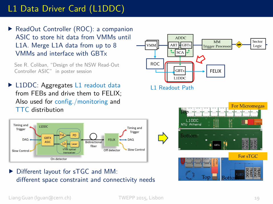
L1 Data Driver Card (L1DDC)
L1DDC: Aggregates L1 readout data from FEBs and drive them to FELIX; Also used for config./monitoring and TTC distribution
Different layout for sTGC and MM:different space constraint and connectivity needs
Liang Guan ([email protected]) TWEPP 2015, Lisbon 19
See R. Coliban, “Design of the NSW Read-Out Controller ASIC” in poster session
ReadOut Controller (ROC): a companion ASIC to store hit data from VMMs until L1A. Merge L1A data from up to 8 VMMs and interface with GBTx
ROC
L1 Readout Path
FELIX
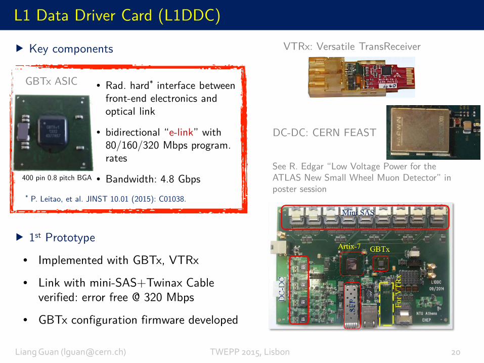
L1 Data Driver Card (L1DDC)
Key components
1st Prototype
• Rad. hard* interface between front-end electronics and optical link
• bidirectional “e-link” with 80/160/320 Mbps program. rates
• Bandwidth: 4.8 Gbps
GBTx ASIC
400 pin 0.8 pitch BGA
VTRx: Versatile TransReceiver
DC-DC: CERN FEAST
See R. Edgar “Low Voltage Power for the ATLAS New Small Wheel Muon Detector” in poster session
• Implemented with GBTx, VTRx
• Link with mini-SAS+Twinax Cable verified: error free @ 320 Mbps
• GBTx configuration firmware developed
For V
TRx
Liang Guan ([email protected]) TWEPP 2015, Lisbon 20
* P. Leitao, et al. JINST 10.01 (2015): C01038.
Conclusions and Outlook
The New Small Wheel Upgrade is necessary for ATLAS to improve the Level-1 trigger in order to maintain crucial physics program in high luminosity environment.
The complex trigger electronics system will be designed to achieve precise on-line muon segment measurements in the forward region of the Muon Spectrometer to discriminate against high-rate backgrounds.
Separate trigger algorithms for two sub-detector systems (MM & sTGC) have been developed, taking account of substantial readout, geometry differences
Significant effort have been made in the design of various trigger electronics in order to be fitted within the tight latency budget.
A vertical slice is under preparation and planned to integrate all NSW electronics.
Liang Guan ([email protected]) TWEPP 2015, Lisbon 21
Thank you for your attention!
Liang Guan ([email protected]) TWEPP 2015, Lisbon 22
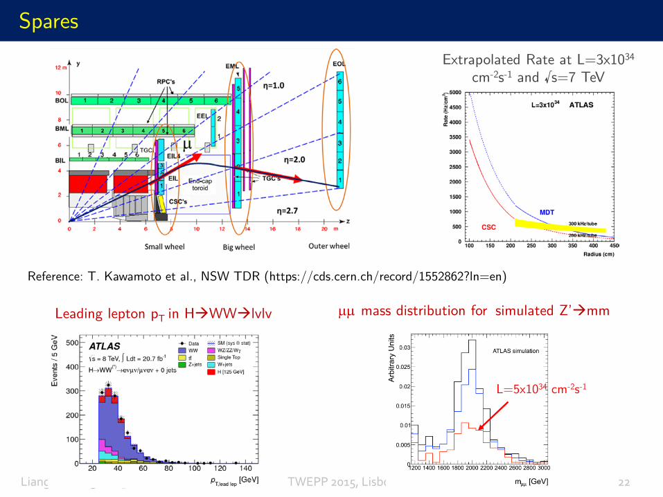
SparesExtrapolated Rate at L=3x1034
cm-2s-1 and √s=7 TeV
Leading lepton pT in HWWlvlv µµ mass distribution for simulated Z’mm
L=5x1034 cm-2s-1
Reference: T. Kawamoto et al., NSW TDR (https://cds.cern.ch/record/1552862?ln=en)
Qua
d.
Cent
roid
Laye
r Cen
troi
dLa
tenc
y
PivotQuadruplet
ConfirmationQuadruplet
Spares
Liang Guan ([email protected]) TWEPP 2015, Lisbon 23
MM
pad strip
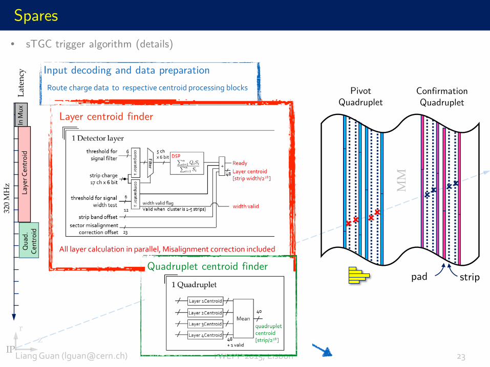
Input decoding and data preparation
Layer centroid finder
All layer calculation in parallel, Misalignment correction included
Route charge data to respective centroid processing blocks
Quadruplet centroid finder
In M
ux
320
MH
z
IPz
r
• sTGC trigger algorithm (details)
Liang Guan ([email protected]) TWEPP 2015, Lisbon 24
Spares
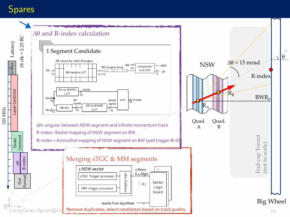
∆θ and R-index calculation
Merging sTGC & MM segments
Remove duplicates, select candidates based on track quality
NSW
Big WheelM
M
∆θ < 15 mradθ
End-
cap
Toro
id
(not
to s
cale
)
Quad. A
Quad.B
BWR0
R-index
RA
RB
r
IPz
∆θ= angular between NSW segment and infinite momentum track
R-index= Radial mapping of NSW segment on BW
Φ-index = Azimuthal mapping of NSW segment on BW (pad trigger Φ-ID)
∆θ
Qua
d.
Cent
roid
Laye
r Cen
troi
dLa
tenc
yIn
Mux
320
MH
z
18 c
lk=
2.25
BC
R-in
dex
Out
Fo
rmat
Liang Guan ([email protected]) TWEPP 2015, Lisbon 25
Spares
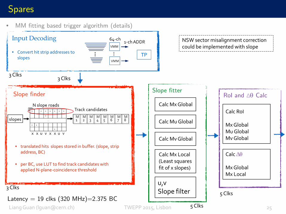
RoI and ∆θ CalcSlope finder
• translated hits slopes stored in buffer. (slope, strip address, BC)
• per BC, use LUT to find track candidates with applied N-plane-coincidence threshold
Slope fitter
Calc Mx Local(Least squares fit of x slopes)
Calc Mx Global
Calc Mu Global
Calc Mv Global
u,v Slope filter
Calc RoI
Mx GlobalMu GlobalMv Global
Calc ∆θ
Mx GlobalMx Local
Input Decoding
• Convert hit strip addresses to slopes
Latency = 19 clks (320 MHz)=2.375 BC
3 Clks3 Clks
3 Clks
5 Clks
5 Clks
NSW sector misalignment correction could be implemented with slope
• MM fitting based trigger algorithm (details)
DeserializerVMM Chnl0
BCID
Ring buffer
DeserializerVMM Chnl127
BCID
Pad Trigger
BCID Strip range: # n:n+k
DeserializerVMM Chnl n
DeserializerVMM Chnl n+k
BCID
Strip # n
Strip # n+k
BCID
BCID
Strip #0Strip #17Strip #34Strip #51
8-1 SEL#0
Strip #68Strip #85Strip #102Strip #119
8-1 SEL#15
160 MHz40 MHz
160 MHz VMM1
160 MHz
40 MHz
PLL
1: VMM Interface 2: Preprocessor 3: Serialization
Serial output
BCID
Fram
e B
uild
and
FIF
O C
ontro
l
GBTSERDM
Pad Trigger
Interface
Pad LUT #0
Pad LUT #1
Pad LUT #2
Pad LUT with TMR
11
11
11
11 11
11
11
11
I2C Configuration
TDS Logic
Pad Trigger
SER
Deserializer
BCID
Deserializer
BCID
Neighbor_bottom x2
Neighbor_top x2 BCID11
11
BCID11
11To
tal 1
7 St
rips l
ines
Scrambler 4.8 Gbps
8-1 SEL#16
Strip #15Strip #32Strip #49Strip #66Strip #83Strip #100Strip #117
000..00
160 MHz VMM2
Strip
-Seq
uenc
er
PRBS-31
TEST
Ban
d ID
+ P
hi ID
BCID
Interested strips
frame
#0
#15
#16
Frame Gen
Serial pattern #0
Serial pattern #16
ePLL
SDASCL
40 MHz
320 MHz
Sampling clock
Spares
Strip-TDS block diagram
Liang Guan ([email protected]) TWEPP 2015, Lisbon 27
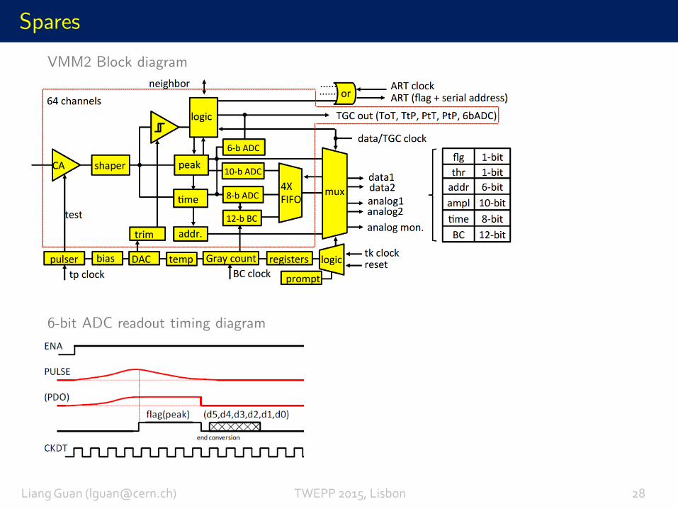
SparesVMM2 Block diagram
6-bit ADC readout timing diagram
Liang Guan ([email protected]) TWEPP 2015, Lisbon 28