Embed Size (px)
Citation preview

engl
ish
deut
sch
fran
çais
ital
iano
espa
ñol
Manual 1.1
Important:Before powering up please read the Important SafetyInstructions on page 53 - 55!
Wichtig:Bitte lies vor der Inbetriebnahme unbedingt dieSicherheitshinweise auf Seite 53 - 55!
Attention :Avant la mise en fonction de l’appareil, il est fortementrecommandé de prendre connaissance des mesures deprudence présentées aux pages 53 - 55 !
Importante:Prima di utilizzare lo strumento leggete attentamente gli avvisidi sicurezza su pagina 53 - 55!
Importante:¡ Por favor antes de la puesta en servicio debes leernecesariamente las instrucciones de seguridad en la página 53 - 55 !
Trilogy™ Manual 1.1
Für das folgend bezeichnete Erzeugnis
Trilogy™
wird hiermit bestätigt, dass es den wesentlichen Schutz-anforderungen entspricht, die in der Richtlinie des Rates zurAngleichung der Rechtsvorschriften der Mitgliedsstaatenüber die elektromagnetische Verträglichkeit (89/336/EWG)und der Niederspannungsrichtlinie (73/23/EWG) festgelegtsind. Diese Erklärung gilt für alle Exemplare und bestätigtdie Ergebnisse der Messungen, die durch die Qualitäts-sicherung der Fa. Stamer Musikanlagen GmbH durchgeführtwurden. Zur Beurteilung des Erzeugnisses hinsichtlichelektromagnetischer Verträglichkeit wurden folgendeNormen herangezogen: EN 50081-1 • EN 50082-1. Zur Beurteilung der Einhaltung der Niederspannungsrichtliniewurde folgende Norm herangezogen: EN 60065
Diese Erklärung wird verantwortlich für den Hersteller
abgegeben durch
Lothar Stamer Dipl.Ing.GeschäftsführerSt.Wendel, den 17/02/2005
* Stamer Musikanlagen stellt exklusiv für Hughes & Kettner® her.
Stamer Musikanlagen GmbH*Magdeburger Str. 866606 St.Wendel
This is to certify that
Trilogy™
complies with the provisions of the Directive of the Councilof the European Communities on the approximation of thelaws of the Member States relating to electromagneticcompatibility (EMC Directive 89/336/EEC) and the low voltageDirective (73/23/EEC). This declaration of conformity of theEuropean Communities is the result of an examination carriedout by the Quality Assurance Department of STAMER GmbHin accordance with European Standards EN 50081-1, EN 50082-1and EN 60065 for low voltage, as laid down in Article 10 of the EMC Directive.
Lothar Stamer Dipl.Ing.Managing DirectorSt.Wendel, 02/17/2005
* Stamer Musikanlagen manufactures exclusively for Hughes & Kettner®.
Stamer Musikanlagen GmbH*Magdeburger Str. 866606 St.Wendel
3
Foreword
Even in the new millennium, classic rock, blues and metalsounds of last century’s great guitarists continue to shapemusicians and audiences’ tastes in tone. Back in the day,flexibility wasn’t top on the list of amp attributes: Two channelswere standard, three a luxury, and four MIDI switchable channelsa dream at best. And now monster nu metal sounds, detunedguitars, blistering bare-knuckle riffs and clean yet heavily effectedsounds have gained currency in the repertoires of countlessrock bands. Yesteryear’s tube amps are no match for today’ssonic diversity challenge.
Enter Trilogy™. You have chosen a tube amp offering a richfeature set. Its mighty arsenal of sound-sculpting features that makes the dream of total mastery over tone come true. It boasts four independent channels tweaked to delivermarkedly different slices of the tonal pie, a further variation on the fundamental sound in the CLEAN and CRUNCH channelseach, and a whopping 128 effect combinations that can bestored via MIDI in combination with these six sounds. In anutshell, you get plenty of sonic firepower to make every gig pure playing pleasure.
Things to do before operating
the Amp
A word of warning before you fire up your new amp: It’s loud!High volume levels can cause hearing damage. Always twistthe MASTER VOLUME knob to the far left-hand position beforeturning on the amp, and then slowly rotate the knob clockwiseuntil you dial in a level that is comfortable for your ears andsuitable for the venue. Keep those levels well under the painthreshold!
Check the voltage rating displayed next to Trilogy™'s MAINSINPUT to make sure it matches your local mains current beforeyou plug the amp in. Ensure plenty of air can circulate aroundyour amp's ventilation ducts. Place the amp on a sturdy, securebase and avoid exposing it to mechanical shocks and extremetemperatures that could endanger the device or your andothers' safety.
The manufacturer disclaims any liability or responsibility what-soever for any damage or defect to this and other devicesresulting from misuse.
Powering up
First plug the speaker cord into appropriate Speaker Out onthe head’s rear panel. Your choices are a 4-ohm output, a pairof 16-ohm outputs, an 8-ohm output and a 16-ohm output.More on this in chapter 2 – Rear Panel Connections and ControlFeatures. Plug the other end of the cord into the speaker cabinet’sinput. This amp-to-speaker connection and impedance matchingare vital to every all-tube amp’s life! Tube amps operatedwithout the load of a connected speaker or at an insufficientimpedance level die!
Plug the head’s mains cord into a wall outlet and power theamp up by engaging the MAINS switch. Allow the tubes towarm up before you begin playing. First plug one end of theguitar cord into the guitar, and then the other end into theamp. Flip the STANDBY switch to bring those glowing tubes to life.
engl
ish
Trilogy™ Manual 1.1
Table of Contents
1 Front Panel Connections and Control Features . . . . . . . . . . . . . . . 5
1.1 Input . . . . . . . . . . . . . . . . . . . . . . . . . . . . . . . . . . . . . . 5
1.2 Clean Channel . . . . . . . . . . . . . . . . . . . . . . . . . . . . . . . . 5
1.3 Crunch Channel . . . . . . . . . . . . . . . . . . . . . . . . . . . . . . 5
1.4 Lead Channel . . . . . . . . . . . . . . . . . . . . . . . . . . . . . . . . 6
1.5 Ultra Lead Channel . . . . . . . . . . . . . . . . . . . . . . . . . . . . 6
1.6 Master Section . . . . . . . . . . . . . . . . . . . . . . . . . . . . . . . 6
1.7 Mains and Standby Switches . . . . . . . . . . . . . . . . . . . . . . 6
2 Rear Panel Connectionsand Control Features . . . . . . . . . . . . . . . 7
2.1 Mains Socket . . . . . . . . . . . . . . . . . . . . . . . . . . . . . . . . 7
2.2 Anode Fuse . . . . . . . . . . . . . . . . . . . . . . . . . . . . . . . . . 7
2.3 FX Loop On/Off . . . . . . . . . . . . . . . . . . . . . . . . . . . . . . 7
2.4 Channel Select Stageboard . . . . . . . . . . . . . . . . . . . . . . . 7
2.5 FX Send, Level and Return . . . . . . . . . . . . . . . . . . . . . . . 7
2.6 MIDI Port . . . . . . . . . . . . . . . . . . . . . . . . . . . . . . . . . . . 8
2.7 Speakers . . . . . . . . . . . . . . . . . . . . . . . . . . . . . . . . . . . 8
3 Standard Setupand Cable Connections . . . . . . . . . . . . . . . 8
4 Trilogy™ and MIDI . . . . . . . . . . . . . . . . . 84.1 Programming . . . . . . . . . . . . . . . . . . . . . . . . . . . . . . . . 8
4.2 Setting the MIDI Channel and Switching OMNI On/Off . . . . . . 8
4.3 Factory Settings and How to Restore Them . . . . . . . . . . . . 9
5 Replacing Tubes, Service and PreventiveMaintenance . . . . . . . . . . . . . . . . . . . . 10
5.1 When to Replace Tubes . . . . . . . . . . . . . . . . . . . . . . . . 10
5.2 Things to Bear in Mind When Replacing Tubes . . . . . . . . . 10
5.3 How to Prolong Tube Life . . . . . . . . . . . . . . . . . . . . . . . 10
6 Troubleshooting . . . . . . . . . . . . . . . . . . 11
7 Technical Specifications . . . . . . . . . . . . . 12
Trilogy™ Manual 1.1
4
5
engl
ish
Trilogy™ Manual 1.1
MASTER PRESENCE FX-MIX TREBLE MID BASS MASTER ULTRA GAIN LEAD GAIN TREBLE MID BASS MASTER GAIN TREBLE MID BASS VOLUME0 10 -5 +5 0 10 -5 +5 -5 +5 -5 +5 -5 +5 -5 +5 -5 +5 -5 +5 -5 +5 -5 +50 10 0 10 0 10 0 10 0 10 0 10
ULTRA LEAD/LEAD
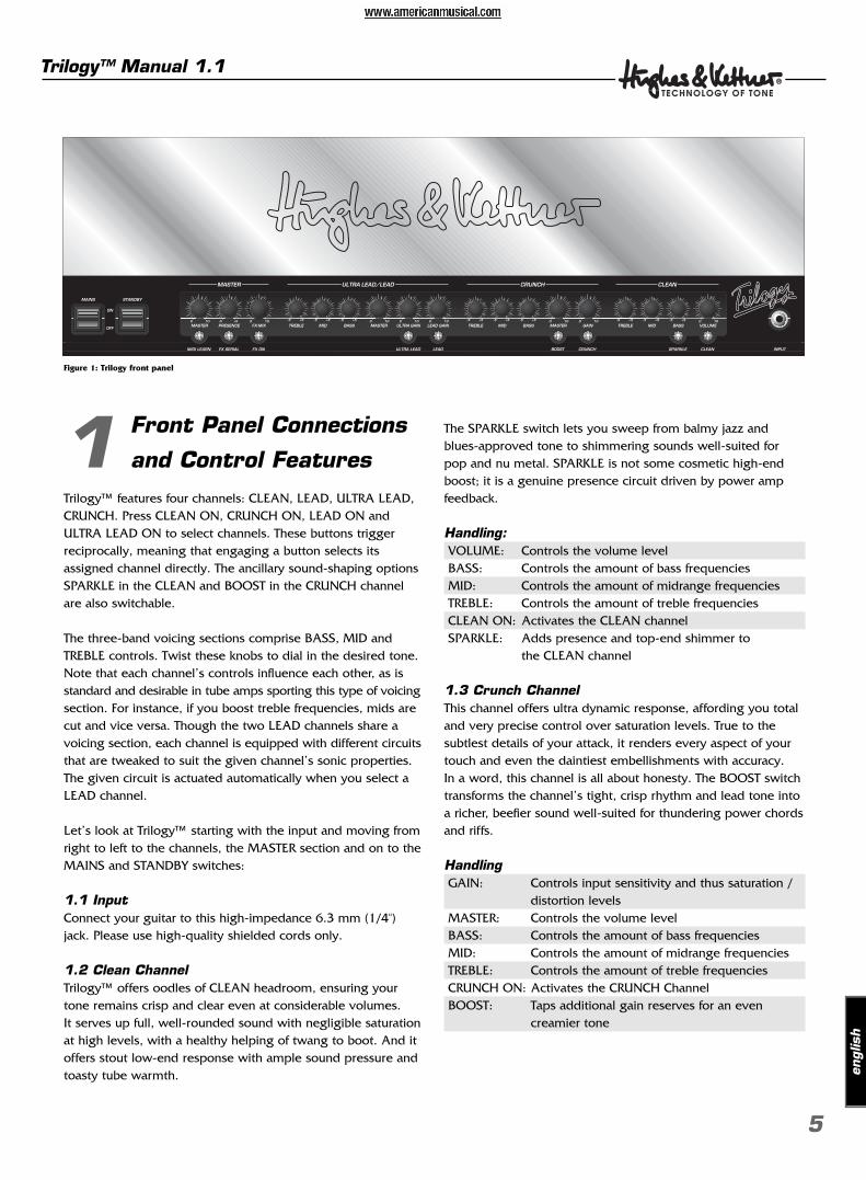
Figure 1: Trilogy front panel
1 Front Panel Connections
and Control Features
Trilogy™ features four channels: CLEAN, LEAD, ULTRA LEAD,CRUNCH. Press CLEAN ON, CRUNCH ON, LEAD ON andULTRA LEAD ON to select channels. These buttons triggerreciprocally, meaning that engaging a button selects itsassigned channel directly. The ancillary sound-shaping optionsSPARKLE in the CLEAN and BOOST in the CRUNCH channelare also switchable.
The three-band voicing sections comprise BASS, MID andTREBLE controls. Twist these knobs to dial in the desired tone.Note that each channel’s controls influence each other, as isstandard and desirable in tube amps sporting this type of voicingsection. For instance, if you boost treble frequencies, mids arecut and vice versa. Though the two LEAD channels share avoicing section, each channel is equipped with different circuitsthat are tweaked to suit the given channel’s sonic properties.The given circuit is actuated automatically when you select aLEAD channel.
Let’s look at Trilogy™ starting with the input and moving fromright to left to the channels, the MASTER section and on to theMAINS and STANDBY switches:
1.1 InputConnect your guitar to this high-impedance 6.3 mm (1/4")jack. Please use high-quality shielded cords only.
1.2 Clean ChannelTrilogy™ offers oodles of CLEAN headroom, ensuring yourtone remains crisp and clear even at considerable volumes. It serves up full, well-rounded sound with negligible saturationat high levels, with a healthy helping of twang to boot. And itoffers stout low-end response with ample sound pressure andtoasty tube warmth.
The SPARKLE switch lets you sweep from balmy jazz andblues-approved tone to shimmering sounds well-suited forpop and nu metal. SPARKLE is not some cosmetic high-endboost; it is a genuine presence circuit driven by power ampfeedback.
Handling:VOLUME: Controls the volume level BASS: Controls the amount of bass frequencies MID: Controls the amount of midrange frequencies TREBLE: Controls the amount of treble frequencies CLEAN ON: Activates the CLEAN channel SPARKLE: Adds presence and top-end shimmer to
the CLEAN channel
1.3 Crunch ChannelThis channel offers ultra dynamic response, affording you totaland very precise control over saturation levels. True to thesubtlest details of your attack, it renders every aspect of yourtouch and even the daintiest embellishments with accuracy. In a word, this channel is all about honesty. The BOOST switchtransforms the channel’s tight, crisp rhythm and lead tone intoa richer, beefier sound well-suited for thundering power chordsand riffs.
Handling GAIN: Controls input sensitivity and thus saturation /
distortion levels MASTER: Controls the volume level BASS: Controls the amount of bass frequencies MID: Controls the amount of midrange frequencies TREBLE: Controls the amount of treble frequencies CRUNCH ON: Activates the CRUNCH Channel BOOST: Taps additional gain reserves for an even
creamier tone
1.4 Lead ChannelArticulate distorted tone plays a pivotal role in most players’decision to buy an amp. A chief criterion for a top-notch guitaramp is its ability to retain the guitar’s character and deliverdefined tone even with the GAIN knob cranked. Trilogy™ does this; what’s more, its LEAD sound is an excellent vehicle for classic rock leads and crashing power chords.
1.5 Ultra Lead ChannelDive into a deep reservoir of distortion and let powerful sonic waves wash over you with every head-banging riff. The ULTRA GAIN channel delivers American-style high-gaintone with trouser leg-flapping low end and plenty of top-endslice. Hot and bad, this channel’s distorted tone is what thegood doctor ordered for nu-metal and drop-D styles. It alsoserves up sumo-sized lead tone for all other genres.
Handling:LEAD-GAIN: Controls the amount distortion in
the LEAD channelULTRA-LEAD-GAIN: Controls the amount distortion in
the ULTRA LEAD channelMASTER: Controls the volume levelBASS: Controls the amount of bass frequencies
in both channelsMID: Controls the amount of midrange fre-
quencies in both channelsTREBLE: Controls the amount of treble frequen-
cies in both channelsLEAD ON: Activates the LEAD channel (for a lean,
mean classic British tone)ULTRA LEAD ON: Activates the ULTRA LEAD channel (for
chunky American sounds)
1.6 Master SectionThe master section lets you dial in Trilogy™’s overall outputlevel, control presence, route effects and adjust the dry/wetbalance, as well as “teach” the amp to respond to MIDIprogram change messages.
Handling:FX-MIX, FX ON and SERIAL
SmartLoop™ is a special effects routing circuit offering aswitchable parallel/serial effects loop. In parallel mode,(SERIAL is deactivated) the processed signal is added to the original signal of the preamp. Twist the FX-MIX knob toadjust the dry/wet balance, that is, the ratio of unprocessed to processed signal. Generally the best results are achieved by programming or setting the signal processor’s output to100% so that only the wet effected signal and no dry signal is patched out of the effect device.
In serial mode (SERIAL is activated), SmartLoop™ works like aconventional serial effects loop. This means you must adjustthe wet/dry balance on the signal processor.
Tip:If you have not inserted an effect device into the FX loop, youcan use this circuit for a variety of other purposes:• In parallel mode, you can use the RETURN jack to connect
a second instrument or any other audio source, and thenblend its signal with the guitar signal using the FX MIX knob. You can also route the amp’s signal to a second power ampor through a RED BOX® to a mixing console.
• When in serial mode and bridged (SEND and RETURN jacksare connected using a cord equipped with 1/4" jack plugs),the effects loop can serve as a second master preset thatmay be activated for each channel via a footswitch. Use theFX-MIX knob to adjust the volume level.
x Note:Be sure to connect a signal processor when the effects loop is configured in serial mode. Otherwise, the signal chain isinterrupted and you will not hear your guitar’s signal!
PRESENCEThis knob determines the overtone content for all channels.
MASTERAs its name would indicate, this knob puts you in charge ofthe EL-34 power amp tubes and the100 watts of power theyput out. Though this knob promises tons of tweaking fun, plea-se exercise restraint and caution.
MIDI LEARNAssigns the given amp settings to a MIDI program numberand serves to determine the amp’s basic MIDI configuration.For more on this, see section 4 – MIDI.
1.7 Mains and Standby SwitchesMAINS ON/OFF
This button switches the main power supply on and tubes theopportunity to warm up for the work ahead.
STANDBYThis switch controls the high voltage power supply to thetubes. When engaged, anode voltage is applied to the tubes'filaments only so that the tubes remain warm and ready torock. When taking a short break from playing, please useSTANDBY rather than ON/OFF so the tubes remain at operatingtemperature.
Trilogy™ Manual 1.1
6
7
engl
ish
Trilogy™ Manual 1.1
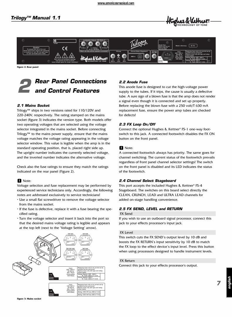
Figure 2: Rear panel
Figure 3: Mains socket
2 Rear Panel Connections
and Control Features
2.1 Mains SocketTrilogy™ ships in two versions rated for 110/120V and 220-240V, respectively. The rating stamped on the mainssocket (figure 3) indicates the version type. Both models offertwo operating voltages that are selected using the voltageselector integrated in the mains socket. Before connectingTrilogy™ to the mains power supply, ensure that the mainsvoltage matches the voltage rating appearing in the voltageselector window. This value is legible when the amp is in thestandard operating position, that is, placed right side up. The upright number indicates the currently selected voltage,and the inverted number indicates the alternative voltage.
Check also the fuse ratings to ensure they match the ratingsindicated on the rear panel (Figure 2).
x Note:Voltage selection and fuse replacement may be performed byexperienced service technicians only. Accordingly, the followingnotes are addressed exclusively to service technicians!• Use a small flat screwdriver to remove the voltage selector
from the mains socket.• If the fuse is defective, replace it with a fuse bearing the spe-
cified rating.• Turn the voltage selector and insert it back into the port so
that the desired mains voltage rating is legible and appearsat the top left (next to the "Voltage Setting" arrow).
2.2 Anode FuseThis anode fuse is designed to cut the high-voltage powersupply to the tubes. If it trips, the cause is usually a defectivetube. A sure sign of a blown fuse is that the amp does not rendera signal even though it is connected and set up properly.Before replacing the blown fuse with a 250 volt/T 630 mAreplacement fuse, ensure the power amp tubes are checkedfor defects!
2.3 FX Loop On/OffConnect the optional Hughes & Kettner® FS-1 one-way foot-switch to this jack. A connected footswitch disables the FX ONbutton on the front panel.
x Note: A connected footswitch always has priority. The same goes forchannel switching: The current status of the footswitch prevailsregardless of front panel channel selector settings! The switchon the front panel is disabled and its LED indicates the statusof the footswitch.
2.4 Channel Select StageboardThis port accepts the included Hughes & Kettner® FS-4Stageboard. The switches on this board select directly theCLEAN, CRUNCH, LEAD and ULTRA LEAD channels for added on-stage handling convenience.
2.5 FX SEND, LEVEL and RETURN FX Send
If you wish to use an outboard signal processor, connect thisjack to your effects processor's input jack.
FX LevelThis switch cuts the FX SEND’s output level by 10 dB andboosts the FX RETURN’s input sensitivity by 10 dB to matchthe FX loop to the effect device’s input level. Press this buttonwhen using processors designed to handle instrument levels.
FX ReturnConnect this jack to your effects processor's output.
2.6 MIDIThis port accepts a MIDI footswitch or another MIDI controlused for switching channels. Switching options are the CLEAN,LEAD, ULTRA-LEAD and CRUNCH channels, effects loop on/offand serial/parallel, as well as the sound-shaping functionsSPARKLE for the CLEAN and BOOST for the CRUNCH channel.For more on this, refer to chapter 4 – TRILOGY AND MIDI.
2.7 SpeakersYou have one 4-ohm output, a pair of 16-ohm outputs or one8-ohm output, and a 16-ohm output available for connectingspeaker cabinets of various impedances. Always ensurecabinets are connect properly. Operating a tube amp with the wrong impedance or without a connected speaker candamage it. For more on this, see also the section in chapter 5entitled How to Prolong Tube Life.
3 Standard Setup and
Cable Connections
4 Trilogy™ and MIDI
For utmost handling ease, use SmartLoop™ in combinationwith a MIDI-enabled multi effector. This lets you control allswitchable functions of Trilogy™ via MIDI, specifically• the 4 channels CLEAN, LEAD, ULTRA LEAD, CRUNCH• the sound-shaping features SPARKLE in the CLEAN channel
and BOOST in the crunch channel• FX ON and the loop’s SERIAL mode
4.1 ProgrammingProgramming couldn’t be any easier. If you want to save aconfiguration such as CRUNCH with BOOST, FX and SERIALactivated, simply arm Trilogy™ by briefly pressing the MIDILEARN button (MIDI LEARN lights up), and then pressing thedesired program number on your MIDI board (or other MIDIsend control). The MIDI LEARN light extinguishes to indicateTrilogy™ has assigned this configuration to the programnumber selected on your foot board.
Now when Trilogy™ receives a program change message via the selected MIDI channel (more on this below), the MIDI LEARN LED flashes briefly and Trilogy™ is configuredaccordingly.
To discontinue programming without saving settings onceMIDI LEARN is armed, simply press the button again.
4.2 Setting the MIDI Channel and Switching OMNI On/OffIf you press and hold the MIDI LEARN button for more thantwo seconds when Trilogy™ is in normal operating mode, itsLED animates. The flashing light indicates special programmingfunctions are now assigned to the amp’s buttons and LEDs:
CLEANNow serves as an up button. Use it to select the MIDI channelone-step increments (+1). The factory default is MIDI channel 1.
SPARKLENow serves as a down button with one-step increments (-1).
FX ONSwitches OMNI on/off.
x Note:OMNI enables reception on all channels. This option is a goodchoice if you’re unsure which channel your foot board uses tosend messages.
Trilogy™ Manual 1.1
8
MASTER PRESENCE FX-MIX TREBLE MID BASS MASTER ULTRA GAIN LEAD GAIN TREBLE MID BASS MASTER GAIN TREBLE MID BASS VOLUME0 10 -5 +5 0 10 -5 +5 -5 +5 -5 +5 -5 +5 -5 +5 -5 +5 -5 +5 -5 +5 -5 +50 10 0 10 0 10 0 10 0 10 0 10
ULTRA LEAD/LEAD
9
engl
ish
Trilogy™ Manual 1.1
MIDI LEARNStores your settings, quits the MIDI setup menu and returnsthe amp to normal operating mode.
SERIAL:Press this button to check if all LEDs are working properly. All LEDs on Trilogy™’s front panel must light up for as long as you press and hold SERIAL.
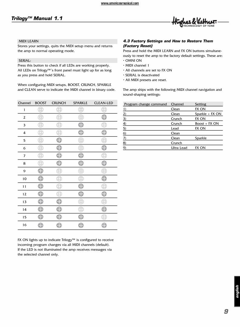
When configuring MIDI setups, BOOST, CRUNCH, SPARKLEand CLEAN serve to indicate the MIDI channel in binary code.
Channel BOOST CRUNCH SPARKLE CLEAN-LED
1
2
3
4
5
6
7
8
9
10
11
12
13
14
15
16
FX ON lights up to indicate Trilogy™ is configured to receiveincoming program changes via all MIDI channels (default). If the LED is not illuminated the amp receives messages viathe selected channel only.
4.3 Factory Settings and How to Restore Them(Factory Reset)Press and hold the MIDI LEARN and FX ON buttons simultane-ously to reset the amp to the factory default settings. These are:• OMNI ON• MIDI channel 1• All channels are set to FX ON• SERIAL is deactivated• All MIDI presets are reset.
The amp ships with the following MIDI channel navigation andsound-shaping settings:
Program change command Channel Setting1) Clean FX ON2) Clean Sparkle + FX ON3) Crunch FX ON4) Crunch Boost + FX ON5) Lead FX ON6) Clean7) Clean Sparkle8) Crunch 9) Ultra Lead FX ON
5 Replacing Tubes,
Service and
preventive Maintenance
TRILOGY™ is factory-loaded with EL34 and 12AX7 tubes.Once they’ve been burned in – that is, operated continuouslyunder a load – they are subjected to a rigorous selection process.Their electrical specs and mechanical status (microphonics) arechecked, and then they are installed in an amp and sound-checked. One of the most important steps in this process istube matching, whereby tubes with the same characteristicsare teamed up in matched sets of power tubes.
5.1 When to Replace TubesThe tubes in TRILOGY™ are exemplary in terms of quality,workmanship and long service life. In the unlikely event thatyou encounter a problem, please run down the followingchecklist before you swap your old tubes for a new set: Was the fault or failure of the power tube caused by the tubeitself or by a flawed peripheral device or component, perhapsa defective speaker cable? (If you don’t get to the bottom ofthe problem and remedy it, it may crop up again even afteryou replace the tubes.)
Did the mains voltage fluctuate or spike while the amp wason? In all-tube amps, over-voltage surges in the mains net cancertainly cause drop-outs. Over-voltages are often caused bygenerators and faulty high-current power circuits. Perhaps afuse blew even though none of the tubes is actually defective?An old fuse, tube de-ionization or mains voltage power surgesmay have triggered the fuse. In this case, replacing tubes is awaste of money, time and effort.
Tubes show definite signs of wear when their service life isnearing its end. Telltale signs are increased microphonics, noiseand hiss, muddier tone through loss of high-end frequencies,degraded performance, etc. Take these indications seriouslyand replace old tubes. Not only do these side effects take theirtoll on sound quality, they also indicate the aging tube willsoon fail!
x Note:Replacing tubes for experimentation purposes is not recom-mended. Installing the wrong tubes will damage the amp andcost you a lot more than you bargained for in repair costs.
5.2 Things to Bear in Mind When Replacing TubesThe golden rule is that replacing tubes is a job best left toqualified professionals. Accordingly, the following guidelinesare addressed and apply to qualified service technicians only:
Pull TRILOGY™’s mains plug and allow for a discharge time ofat least two minutes before removing the chassis from the rearof the amp. Once the chassis has been removed, carefully easethe tubes out of their sockets. A single power tube may onlybe replaced if the replacement tube precisely matches theoriginal, that is, the old and new tubes’ characteristics areidentical. As a rule, use matched sets only when replacingpower tubes. When a new set of power tubes with characteristicsidentical to the old set is installed, it is not absolutely necessaryto re-bias the amp. However, the amp must be biased when a replacements set’s characteristics do not match the originalset’s. This requires experience and extensive working know-ledge in measuring techniques, which is why this is a job forqualified technicians with tube amp tuning experience.
5.3 How to Prolong Tube Life• Never operate Trilogy™ without connecting a load (loud-
speaker)! To this end, always use high-quality, heavy-dutyspeaker cords that won’t crimp.
• Use the STANDBY switch! Heating up tubes frequently shortenstube life. Cut anode voltage using the STANDBY function todecrease operating hours and extend tube life.
• Avoid exposing the amp to vibrations, especially when it’spowered up. Switch the amp off well before transporting it to allow tubes to cool off completely.
• Make sure all peripheral devices and connecting cords are ina state of good repair! Ensure air can circulate freely aroundthe amp’s ventilation slots at all timesæyour Trilogy™’s lifedepends on it.
• Never expose the amp to extreme heat, heavy dust and, par-ticularly, moisture.
• Always check peripheral gear’s specs to ensure theseaccessories are suitable for the amp. Never connect speakercabinets with an impedance (ohm) rating lower thanTrilogy™ is designed to handle.
• Never connect devices with high output signal levels (e.g.power amps) to Trilogy™’s input.
• Check the mains power rating before plugging the amp in.When in doubt ask the venue’s sound technician or facilityengineer.
• Refrain from DIY repairs! Also have a qualified technicianreplace internal fuses.
Trilogy™ Manual 1.1
10
11
6 Troubleshooting
Trilogy™ won’t power up when you switch it on.• It‘s not getting AC power. Check the mains cord to see if
it is connected and firmly seated.• The mains fuse is defective. Ensure it is replaced with another
fuse of the same rating.
Trilogy™ is connected properly, but no sound is audible.• The amp is set to STANDBY.• The GAIN or MASTER knob is turned all the way down.• The effects loop is active. • The anode fuse has blown. Before having it replaced with a
fuse of the same rating, have the power amp tubes checkedfor defects.
• The fuse for the tube heating tripped (the tubes don’t glow).Ensure that it is replaced with a fuse bearing the same rating.Always have a service technician replace fuses.
The sound is washed out or muddy when you switchan effects processor on.• The signal processor provides a wet signal that is blended
with the dry or original signal. Depending on the type ofeffect, the processor may be returning a dry signal backalong with wet signal, which causes phase cancellationswhen mixed to the dry signal in Trilogy™’s parallel loop. To prevent phase cancellations, switch the effects loop to SERIAL or turn the dry signal all the way down on thesignal processor.
The amp starts making ringing or hissing noises.• One or several tubes are microphonic. Replace the defective
tube with another of the same type.
Signs of tube wear such as increased microphonicsand noise, treble loss, weak power output or muddysound begin reappearing just a few hours afterreplacing tubes.• The wrong tubes were installed when old tubes were replaced
or the amp was not biased properly. Take the amp to aprofessional to correct the problem.
engl
ish
Trilogy™ Manual 1.1
7 Technical Specifications
All level indications relate to 0 dBV (1V RMS).
7.1 InputsINPUT
Port: 6.3 mm (1/4")Type: unbalancedInput impedance: 1 MΩSensitivity: - 35 dB Max. input level: +8 dB
FX RETURNPort: 6.3 mm (1/4")Type: unbalancedInput impedance: 48 kΩ
Max. sensitivity:-10dB button engaged: -18 dB-10dB button unengaged: -8 dB
Max. input level:-10dB button engaged: + 5 dB-10dB button unengaged: +15dB
7.2 Outputs:FX LOOP Send L/R:
Port: 6.3 mm (1/4")Type: unbalancedOutput impedance: 2.2 kΩOutput level: - 6 dB
Max. output level:-10dB button engaged: + 2 dB-10dB button unengaged: +12 dB
Speaker outputs:Quantity: 4 Port: 6.3 mm (1/4")Type: unbalancedImpedance: 1 X 4 Ω ; 1 X 8 Ω or 2 X 16 Ω ; 1 X 16 Ω
7.3 General Electrical Data:Max. current consumption: 1.35 A @ 230 V AC, 4-8-16 Ω
2.55 A @ 120 V AC, 4-8-16 Ω2.85 A @ 100 V AC, 4-8-16 Ω
Max. power consumption: 383 VA @ 253 V AC, 4-8-16 ΩMains voltage tolerance range: +/- 10 %Ambient temperature range: - 10 °C to +35 °CExternal fuses: 1 x T 630 mA (anode)Internal fuses: 1 x TT 10 A Slo Blo, 2 x T 630 mA
Mains fuses:Europe: (variable: 220 V-230 V or 240 V)2 x 250 V / T 1.6 A (5 x 20mm)
USA/Canada/Asia: (variable: 100 V or 120 V)2 x 250 V / T 4 A (5 x 20mm)
Anode fuse: 1 x T 630 mA
7.4 General Mechanical Data:Dimensions:
Width: 744 mm (incl. corners )Height: 280 mm (incl. handles and feet)Depth: 258 mm (incl. corners)
Weight: 20.5 kg
Trilogy™ Manual 1.1
12
53
IMPORTANT SAFETY INSTRUCTIONSBEFORE CONNECTING, READ INSTRUCTIONS
• Read all of these instructions!• Save these instructions for later use!• Follow all warnings and instructions marked on the product!• Do not use this product near water, i.e. bathtub, sink, swimming pool, wet basement, etc.• Do not place this product on an unstable cart, stand or table. The product may fall, causing
serious damage to the product or to persons!• Slots and openings in the cabinet and the back or bottom are provided for ventilation; to
ensure reliable operation of the product and to protect it from overheating, these openingsmust not be blocked or covered. This product should not be placed in a built-in installation unless proper ventilation is provided.
• This product should not be placed near a source of heat such as a stove, radiator, or anotherheat producing amplifier.
• Use only the supplied power supply or power cord. If you are not sure of the type ofpower available, consult your dealer or local power company.
• Do not allow anything to rest on the power cord. Do not locate this product where personswill walk on the cord.
• Never break off the ground pin on the power supply cord.• Power supply cords should always be handled carefully. Periodically check cords for cuts
or sign of stress, especially at the plug and the point where the cord exits the unit.• The power supply cord should be unplugged when the unit is to be unused for long
periods of time.• If this product is to be mounted in an equipment rack, rear support should be provided.• This product should be used only with a cart or stand that is recommended by
Hughes & Kettner.• Never push objects of any kind into this product through cabinet slots as they may touch
dangerous voltage points or short out parts that could result in risk of fire or electric shock.Never spill liquid of any kind on the product.
• Do not attempt to service this product yourself, as opening or removing covers may expo-se you to dangerous voltage points or other risks. Refer all servicing to qualified servicepersonnel.
• Clean only with dry cloth.• Do not defeat the safety purpose of the polarized or grounding-type plug. A polarized
plug has two blades with one wider than the other. A grounding type plug has two bladesand a third grounding prong. The wide blade or the third prong are -provided for the safety.If the provided plug does not fit into your outlet, consult an electrician for replacement ofthe obsolete outlet.
• Unplug this product from the wall outlet and refer servicing to qualified service personnelunder the following conditions:• When the power cord or plug is damaged or frayed.• If liquid has been spilled into the product.• If the product has been exposed to rain or water.• If the product does not operate normally when the operating instructions are followed.• If the product has been dropped or the cabinet has been damaged.• If the product exhibits a distinct change in performance, indicating a need of service!
• Adjust only these controls that are covered by the operating instructions since improperadjustment of other controls may result in damage and will often require exten-sive workby a qualified technician to restore the product to normal operation.
• Exposure to extremely high noise levels may cause a permanent hearing loss. • Individuals vary considerably in susceptibility to noise induced hearing loss, but nearly every-
one will lose some hearing if exposed to sufficiently intense noise for a sufficient time.
The U.S. Government´s Occupational Safety and Health Administration (OSHA) has specifiedthe following permissible noise level exposures:
Duration Per Day In Hours Sound Level dBA, Slow Response8 906 924 953 972 100
1 1/2 1021 105
1/2 1101/4 or less 115
• According to OSHA, any exposure in excess of the above permissible limits could result insome hearing loss.
• Ear plug protectors in the ear canals or over the ears must be worn when operating thisamplification system in order to prevent a permanent hearing loss if exposure is in excessof the limits as set forth above. To ensure against potentially dangerous exposure to highsound pressure levels, it is recommended that all persons exposed to equipment capableof producing high sound pressure levels such as this amplification system be protected byhearing protectors while this unit is in operation.
• Fuses: Replace with IEC 127 (5 x 20 mms) type and rated fuse for best performance only
TO PREVENT THE RISK OF FIRE AND SHOCK HAZARD, DO NOT EXPOSE THIS APPLIANCETO MOISTURE OR RAIN. DO NOT OPEN CASE; NO USER SERVICE-ABLE PARTS INSIDE.REFER SERVICING TO QUALIFIED SERVICE PERSONNEL.
united states deutsch
WICHTIGE SICHERHEITSHINWEISE!BITTE VOR GEBRAUCH LESEN UND FÜR SPÄTEREN GEBRAUCH AUFBEWAHREN!
• Das Gerät wurde von Hughes & Kettner gemäss IEC 60065 gebaut und hat das Werk in sicher-heitstechnisch einwandfreiem Zustand verlassen. Um diesen Zustand zu erhalten und einengefahrlosen Betrieb sicherzustellen, muss der Anwender die Hinweise und die Warnvermerkebeachten, die in der Bedienungsanleitung enthalten sind. Das Gerät entspricht der Schutzklasse I(schutzgeerdet).
• DIE SICHERHEIT, ZUVERLÄSSIGKEIT UND LEISTUNG DES GERÄTES WIRD VON HUGHES & KETTNER NUR DANN GEWÄHRLEISTET, WENN:
• Montage, Erweiterung, Neueinstellung, Änderungen oder Reparaturen von Hughes & Kettneroder von dazu ermächtigten Personen ausgeführt werden.
• die elektrische Installation des betreffenden Raumes den Anforderungen von IEC (ANSI)-Festlegungen entspricht.
• das Gerät in Übereinstimmung mit der Gebrauchsanweisung verwendet wird.
WARNUNG:• Wenn Abdeckungen geöffnet oder Gehäuseteile entfernt werden, außer wenn dies von Hand
möglich ist, können Teile freigelegt werden, die Spannung führen.• Wenn ein Öffnen des Gerätes erforderlich ist, muss das Gerät von allen Spannungsquellen
getrennt sein. Berücksichtigen Sie dies vor dem Abgleich, vor einer Wartung, vor einerInstandsetzung und vor einem Austausch von Teilen.
• Ein Abgleich, eine Wartung oder eine Reparatur am geöffneten Gerät unter Spannung darf nurdurch eine vom Hersteller autorisierte Fachkraft (nach VBG 4) geschehen, die mit den verbunde-nen Gefahren vertraut ist.
• Lautsprecher-Ausgänge, die mit dem IEC 417/5036-Zeichen (Abb.1, s.unten) versehen sindkönnen berührungsgefährliche Spannungen führen. Deshalb vor dem Einschalten des GerätesVerbindung nur mit dem vom Hersteller empfohlenen Anschlusskabel zum Lautsprecher her-stellen.
• Alle Stecker an Verbindungskabeln müssen mit dem Gehäuse verschraubt oder verriegelt sein,sofern möglich.
• Es dürfen nur Sicherungen vom Typ IEC 127 und der angegebenen Nennstromstärke als Ersatzverwendet werden.
• Eine Verwendung von geflickten Sicherungen oder Kurzschließen des Halters ist unzulässig.• Niemals die Schutzleiterverbindung unterbrechen.• Oberflächen, die mit dem „HOT“-Zeichen (Abb.2, s.unten) versehen sind, Rückwände oder
Abdeckungen mit Kühlschlitzen, Kühlkörper und deren Abdeckungen, sowie Röhren und derenAbdeckungen können im Betrieb erhöhte Temperaturen annehmen und sollten deshalb nichtberührt werden.
• Hohe Lautstärkepegel können dauernde Gehörschäden verursachen. Vermeiden Sie deshalb diedirekte Nähe von Lautsprechern, die mit hohen Pegeln betrieben werden. Verwenden Sie einenGehörschutz bei dauernder Einwirkung hoher Pegel.
NETZANSCHLUSS:• Das Gerät ist für Dauerbetrieb ausgelegt.• Die eingestellte Betriebsspannung muss mit der örtlichen Netzspannung übereinstimmen.• Achtung: Der Netzschalter des Gerätes muss in OFF-Position stehen, wenn das Netzkabel ange-
schlossen wird.• Der Anschluss an das Stromnetz erfolgt mit dem mitgelieferten Netzteil oder Netzkabel.• Netzteil: Eine beschädigte Anschlussleitung kann nicht ersetzt werden. Das Netzteil darf nicht
mehr betrieben werden.• Vermeiden Sie einen Anschluss an das Stromnetz in Verteilerdosen zusammen mit vielen
anderen Stromverbrauchern.• Die Steckdose für die Stromversorgung muss nahe am Gerät angebracht und leicht zugänglich
sein.
AUFSTELLUNGSORT:• Das Gerät sollte nur auf einer sauberen, waagerechten Arbeitsfläche stehen.• Das Gerät darf während des Betriebs keinen Erschütterungen ausgesetzt sein.• Feuchtigkeit und Staub sind nach Möglichkeit fernzuhalten.• Das Gerät darf nicht in der Nähe von Wasser, Badewanne, Waschbecken, Küchenspüle, Nass-
raum, Swimmingpool oder feuchten Räumen betrieben werden. Keine mit Flüssigkeit gefülltenGegenstände (Vase, Gläser, Flaschen etc) auf das Gerät stellen.
• Sorgen Sie für ausreichende Belüftung der Geräte.• Eventuelle Ventilationsöffnungen dürfen niemals blockiert oder abgedeckt werden. Das Gerät
muss mindestens 20 cm von Wänden entfernt aufgestellt werden. Das Gerät darf nur dann inein Rack eingebaut werden, wenn für ausreichende Ventilation gesorgt ist und die Einbau-anweisungen des Herstellers eingehalten werden.
• Vermeiden Sie direkte Sonneneinstrahlung sowie die unmittelbare Nähe von Heizkörpern undHeizstrahlern oder ähnlicher Geräte.
• Wenn das Gerät plötzlich von einem kalten an einen warmen Ort gebracht wird, kann sich imGeräteinnern Kondens-feuchtigkeit bilden. Dies ist insbesondere bei Röhrengeräten zu beachten.Vor dem Einschalten so lange warten, bis das Gerät Raumtemperatur angenommen hat.
• Zubehör: Das Gerät nicht auf einen instabilen Wagen, Ständer, Dreifuß, Untersatz oder Tischstellen. Wenn das Gerät herunterfällt, kann es Personenschäden verursachen und selbst beschä-digt werden. Verwenden Sie das Gerät nur mit einem vom Hersteller empfohlenen oder zusam-men mit dem Gerät verkauften Wagen, Rack, Ständer, Dreifuß oder Untersatz. Bei derAufstellung des Gerätes müssen die Anweisungen des Herstellers befolgt und muss das vomHersteller empfohlene Aufstellzubehör verwendet werden. Eine Kombination aus Gerät undGestell muss vorsichtigt bewegt werden. Plötzliches Anhalten, übermässige Kraftanwendungund ungleichmässige Böden können das Umkippen der Kombination aus Gerät und Gestellbewirken.
• Zusatzvorrichtungen: Verwenden Sie niemals Zusatzvorrichtungen, die nicht vom Herstellerempfohlen wurden, weil dadurch Unfälle verursacht werden können.
• Zum Schutz des Gerätes bei Gewitter oder wenn es längere Zeit nicht beaufsichtigt oderbenutzt wird, sollte der Netzstecker gezogen werden. Dies verhindert Schäden am Gerät auf-grund von Blitzschlag und Spannungsstössen im Wechselstromnetz.
Abb.1 Abb.2
Ver
sion 1
.0 1
0/20
04
54
english francais
IMPORTANT ADVICE ON SAFETY!PLEASE READ BEFORE USE AND KEEP FOR LATER USE!
• The unit has been built by Hughes & Kettner in accordance with IEC 60065 and left thefactory in safe working order. To maintain this condition and ensure non-risk operation, theuser must follow the advice and warning comments found in the operating instructions. The unit conforms to Protection Class 1 (protectively earthed).
• HUGHES & KETTNER ONLY GUARANTEE THE SAFETY, RELIABILITY AND EFFICIENCY OF THEUNIT IF:
• Assembly, extension, re-adjustment, modifications or repairs are carried out by Hughes &Kettner or by persons authorized to do so.
• The electrical installation of the relevant area complies with the requirements of IEC (ANSI)specifications.
• The unit is used in accordance with the operating instructions.• The unit is regularly checked and tested for electrical safety by a competent technician.
WARNING:• If covers are opened or sections of casing are removed, except where this can be done
manually, live parts can become exposed.• If it is necessary to open the unit this must be isolated from all power sources. Please take
this into account before carrying out adjustments, maintenance, repairs and before replacingparts.
• The appliance can only be insulated from all power sources if the mains connection isunplugged.
• Adjustment, maintenance and repairs carried out when the unit has been opened and is stilllive may only be performed by specialist personnel who are authorized by the manufacturer(in accordance with VBG 4) and who are aware of the associated hazards.
• Loudspeaker outputs which have the IEC 417/5036 symbol (Diagram 1, below) can carryvoltages which are hazardous if they are made contact with. Before the unit is switched on,the loudspeaker should therefore only be connected using the lead recommended by themanufacturer.
• Where possible, all plugs on connection cables must be screwed or locked onto the casing.• Replace fuses only with IEC 127 type and specified rating.• It is not permitted to use repaired fuses or to short-circuit the fuse holder.• Never interrupt the protective conductor connection.• Surfaces which are equipped with the „HOT“ mark (Diagram 2, below), rear panels or covers
with cooling slits, cooling bodies and their covers, as well as tubes and their covers arepurposely designed to dissipate high temperatures and should therefore not be touched.
• High loudspeaker levels can cause permanent hearing damage. You should therefore avoidthe direct vicinity of loudspeakers operating at high levels. Wear hearing protection if continuously exposed to high levels.
MAINS CONNECTION:• The unit is designed for continuous operation.• The set operating voltage must match the local mains supply voltage.• Caution: The unit mains switch must be in position OFF before the mains cable is connected.• The unit is connected to the mains via the supplied power unit or power cable.• Power unit: Never use a damaged connection lead. Any damage must be rectified by a
competent technician.• Avoid connection to the mains supply in distributor boxes together with several other power
consumers.• The plug socket for the power supply must be positioned near the unit and must be easily
accessible.
PLACE OF INSTALLATION:• The unit should stand only on a clean, horizontal working surface.• The unit must not be exposed to vibrations during operation.• Keep away from moisture and dust where possible.• Do not place the unit near water, baths, wash basins, kitchen sinks, wet areas, swimming
pools or damp rooms. Do not place objects containing liquid on the unit - vases, glasses,bottles etc.
• Ensure that the unit is well ventilated.• Any ventilation openings must never be blocked or covered. The unit must be positioned at
least 20 cm away from walls. The unit may only be fitted in a rack if adequate ventilation isensured and if the manufacturer’s installation instructions are followed.
• Keep away from direct sunlight and the immediate vicinity of heating elements and radiantheaters or similar devices.
• If the unit is suddenly moved from a cold to a warm location, condensation can form insideit. This must be taken into account particularly in the case of tube units. Before switching on, wait until the unit has reached room temperature.
• Accessories: Do not place the unit on an unsteady trolley, stand, tripod, base or table. If theunit falls down, it can cause personal injury and itself become damaged. Use the unit onlywith the trolley, rack stand, tripod or base recommended by the manufacturer or purchasedtogether with the unit. When setting the unit up, all the manufacturer’s instructions must be followed and the setup accessories recommended by the manufacturer must be used. Anycombination of unit and stand must be moved carefully. A sudden stop, excessive use offorce and uneven floors can cause the combination of unit and stand to tip over.
• Additional equipment: Never use additional equipment which has not been recommendedby the manufacturer as this can cause accidents.
• To protect the unit during bad weather or when left unattended for prolonged periods, themains plug should be disconnected. This prevents the unit being damaged by lightning andpower surges in the AC mains supply.
Diagram 1: Diagram 2:
CONSEILS DE SECURITE IMPORTANTS!PRIERE DE LIRE AVANT L’EMPLOI ET A CONSERVER POUR UTILISATION ULTERIEURE!
• L’appareil a été conçu par Hughes & Kettner selon la norme IEC 60065 et a -quitté l’entre-prise dans un état irréprochable. Afin de conserver cet état et d’assurer un fonctionnementsans danger de l’appareil nous conseillons à l’utilisateur la lecture des indications de sécuritécontenues dans le mode d’emploi. L’appareil est conforme à la classification I (mise à terrede protection).
• SURETE, FIABILITE ET EFFICACITE DE L’APPAREIL NE SONT GARANTIS PAR HUGHES & KETTNER QUE SI:
• Montage, extension, nouveau réglage, modification ou réparation sont -effectués parHughes & Kettner ou par toute personne autorisée par Hughes & Kettner.
• L’installation électrique de la pièce concernée correspond aux normes IEC (ANSI).• L’utilisation de l’appareil suit le mode d’emploi.
AVERTISSEMENT• A moins que cela ne soit manuellement possible, tout enlèvement ou ouverture du boîtier
peut entrainer la mise au jour de pieces sous tension.• Si l’ouverture de l’appareil est nécessaire, celui-ci doit être coupé de chaque source de cou-
rant. Ceci est à prendre en considération avant tout ajustement, entretien, réparation ouchangement de pieces.
• Ajustement, entretien ou réparation sur l’appareil ouvert et sous tension ne -peuvent êtreéffectués que par un spécialiste autorisé par le fabricant (selon VBG4). Le spécialiste étantconscient des dangers liés à ce genre de -réparation.
• Les sorties de baffles qui portent le signe IEC 417/5036 (fig. 1, voir en bas) -peuvent êtresous tension dangereuse. Avant de brancher l’appareil utiliser -uniquement le câble de rac-cordement conseillé par le fabricant pour -raccorder les baffles.
• Toutes les prises des câbles de raccordement doivent être, si possible, vissées ou verrouilléessur le boîtier.
• L‘utilisation de fusibles rafistolés ou court-circuites est inadmissibleseulement: IEC 127.• L’utilisation de fusibles rafistolés ou court-circuites est inadmissible.• Ne jamais interrompre la connexion du circuit protecteur.• Il est conseillé de ne pas toucher aux surfaces pourvues du signe „HOT“ (fig. 2, voir en bas),
aux parois arrières ou caches munis de fentes d’aération, -éléments d’aération et leurs cachesansi qu’aux tubes et leurs caches. Ces -éléments pouvant atteindre des températures élévées pendantl’utilisation de l’appareil.
• Les Niveaux de puissance élévés peuvent entrainer des lésions auditives -durables. Evitezdonc la proximité de haut-parleurs utilisés à haute puissance. Lors de haute puissance conti-nue utilisez une protection auditive.
BRANCHEMENT SUR LE SECTEUR• L’appareil est conçu pour une utilisation continue.• La tension de fonctionnement doit concorder avec la tension secteur locale.• Attention: L’interrupteur de secteur de l’appareil doit être sur la position OFF, -lorsque le
câble de réseau est raccordé.• Le raccordement au réseau éléctrique s’effectue avec l’adaptateur ou le -cordon d´alimenta-
tion livré avec l’appareil.• Adaptateur: Un câble de raccordement abimé ne peut être remplacé. L’adaptateur est
inutilisable.• Evitez un raccordement au réseau par des boîtes de distribution surchargées.• La prise de courant doit être placée à proximité de l’appareil et facile à -atteindre.
LIEU D’INSTALLATION• L’appareil doit être placé sur une surface de travail propre et horizontale.• L’appareil en marche ne doit en aucun cas subir des vibrations.• Evitez dans la mesure du possible poussière et humidité.• L’appareil ne doit pas être placé à proximité d’eau, de baignoire, lavabo, évier, pièce d’eau,
piscine ou dans une pièce humide. Ne placez aucun vase, verre, bouteille ou tout objet rem-pli de liquide sur l’appareil.
• L’appareil doit être suffisamment aéré.• Ne jamais recouvrir les ouvertures d’aération. L’appareil doit être placé à 20 cm du mur au
minimum. L’appareil peut être monté dans un Rack si une -ventilation suffisante est possibleet si les conseils de montage du fabricant sont suivis.
• Evitez les rayons de soleil et la proximité de radiateurs, chauffages etc.• Une condensation d’eau peut se former dans l’appareil si celui-ci est transporté brusque-
ment d’un endroit froid à un endroit chaud. Ceci est particulièrement important pour desappareils à tubes. Avant de brancher l’appareil attendre qu’il ait la température ambiante.
• Accessoires: L’appareil ne doit être placé sur un chariot, support, trépied, bâti ou tableinstable. Une chute de l’appareil peut entrainer aussi bien des -dommages corporels quetechniques. Utilisez l’appareil uniquement avec un chariot, Rack, support, trépied ou bâticonseillé par le fabricant ou vendu en combinaison avec l’appareil. Les indications du fabricantpour l’installation de l’appareil sont à suivre, et les accessoires d’installation conseillés par le-fabricant sont à utiliser. Un ensemble support et appareil doit être déplacé avec précaution.Des mouvements brusques et des revêtements de sol -irreguliers peuvent entrainer la chutede l´ensemble.
• Equipements supplémentaires: Ne jamais utiliser un équipement supplémentaire n’ayant pasété conseillé par le fabricant, ceci pouvant entrainer des -accidents.
• Afin de protéger l’appareil pendant un orage ou s’il ne doit pas être utilisé -pendant un certaintemps, il est conseillé d’enlever la prise au secteur. Ceci évite des dommages dûs à la foudreou à des coups de tension dans le réseau à courant alternatif.
Fig. 1 : Fig. 2 :

To find a local distributor please visit:
www.hughes-and-kettner.com
Hughes & Kettner® • Postfach 1509 • 66595 St. Wendel • Tel. 0 68 51 - 905 0 • FAX 0 68 51 - 905 103International Inquiries: Fax +49 - 68 51 - 905 200 • E-Mail: [email protected]
Technische Änderungen vorbehaltenDetails subject to change without noticeCopyright 2005 Music & Sales P.E. GmbHM
S D
-12
93
04
/2
00
5