Embed Size (px)
Citation preview

Trim: 215 x 276 mm flast.indd 02/28/2015 03:37:28:PM Page VIII
ffirs.indd 02/28/2015 03:33:44:PM Page ITrim: 215 x 276 mm
Illustrated Guide
to Door
Hardware: Design,
Specification,
Selection
Scott Tobias, AHC

Trim: 215 x 276 mm ffirs.indd 02/28/2015 03:33:44:PM Page II
Cover Design: Thomas Nery
Cover Images: Courtesy of Scott J. Tobias, AHC
This book is printed on acid-free paper.
Copyright © 2015 by John Wiley & Sons, Inc. All rights reserved
Published by John Wiley & Sons, Inc., Hoboken, New Jersey
Published simultaneously in Canada
No part of this publication may be reproduced, stored in a retrieval system, or transmitted in any form or by any means,
electronic, mechanical, photocopying, recording, scanning, or otherwise, except as permitted under Section 107 or 108 of the
1976 United States Copyright Act, without either the prior written permission of the Publisher, or authorization through payment
of the appropriate per-copy fee to the Copyright Clearance Center, 222 Rosewood Drive, Danvers, MA 01923, (978) 750-8400,
fax (978) 646-8600, or on the web at www.copyright.com. Requests to the Publisher for permission should be addressed to the
Permissions Department, John Wiley & Sons, Inc., 111 River Street, Hoboken, NJ 07030, (201) 748-6011, fax (201) 748-6008, or
online at www.wiley.com/go/permissions.
Limit of Liability/Disclaimer of Warranty: While the publisher and author have used their best efforts in preparing this book,
they make no representations or warranties with the respect to the accuracy or completeness of the contents of this book and
specifically disclaim any implied warranties of merchantability or fitness for a particular purpose. No warranty may be created or
extended by sales representatives or written sales materials. The advice and strategies contained herein may not be suitable for
your situation. You should consult with a professional where appropriate. Neither the publisher nor the author shall be liable for
damages arising herefrom.
For general information about our other products and services, please contact our Customer Care Department within the United
States at (800) 762-2974, outside the United States at (317) 572-3993 or fax (317) 572-4002.
Wiley publishes in a variety of print and electronic formats and by print-on-demand. Some material included with standard print
versions of this book may not be included in e-books or in print-on-demand. If this book refers to media such as a CD or DVD
that is not included in the version you purchased, you may download this material at http://booksupport.wiley.com. For more
information about Wiley products, visit www.wiley.com.
Library of Congress Cataloging-in-Publication Data:
Tobias, Scott, 1967-
Graphic standards guide to commercial doors and door hardware / Scott Tobias.
pages cm
ISBN 978-1-118-11261-8 (pbk.); ISBN 978-1-118-33310-5 (ebk); ISBN 978-1-118-33027-2 (ebk)
1. Doors. 2. Commercial buildings—Equipment and supplies. 3. Door fittings. I. Title.
TH2278.T63 2014
694’.6—dc23
2014034440
Printed in the United States of America
10 9 8 7 6 5 4 3 2 1
III
ftoc.indd 02/28/2015 03:45:2:PM Page IIITrim: 215 x 276 mm
Contents
Foreword . . . . . . . . . . . . . . . . . . . . . . . . . . . . . . . . . . . . . . . . . . . . . . . . . . . . . . . . . . . . . . VII
Acknowledgments . . . . . . . . . . . . . . . . . . . . . . . . . . . . . . . . . . . . . . . . . . . . . . . . . . . . . . IX
User Guide . . . . . . . . . . . . . . . . . . . . . . . . . . . . . . . . . . . . . . . . . . . . . . . . . . . . . . . . . . . . . . XI
Who This Book Is For . . . . . . . . . . . . . . . . . . . . . . . . . . . . . . . . . . . . . . . . . . . . . . . . . . . . . . . . . . . . . . . . . XI
How This Book Is Organized . . . . . . . . . . . . . . . . . . . . . . . . . . . . . . . . . . . . . . . . . . . . . . . . . . . . . . . . . . XII
How to Use This Book . . . . . . . . . . . . . . . . . . . . . . . . . . . . . . . . . . . . . . . . . . . . . . . . . . . . . . . . . . . . . . . . XII
About the Author . . . . . . . . . . . . . . . . . . . . . . . . . . . . . . . . . . . . . . . . . . . . . . . . . . . . . . . . . . . . . . . . . . . XIII
Introduction . . . . . . . . . . . . . . . . . . . . . . . . . . . . . . . . . . . . . . . . . . . . . . . . . . . . . . . . . . . XV
Associations . . . . . . . . . . . . . . . . . . . . . . . . . . . . . . . . . . . . . . . . . . . . . . . . . . . . . . . . . . . . . . . . . . . . . . . . XV
Codes . . . . . . . . . . . . . . . . . . . . . . . . . . . . . . . . . . . . . . . . . . . . . . . . . . . . . . . . . . . . . . . . . . . . . . . . . . . . . XVIII
Finishes . . . . . . . . . . . . . . . . . . . . . . . . . . . . . . . . . . . . . . . . . . . . . . . . . . . . . . . . . . . . . . . . . . . . . . . . . . . . . XIX
Grades . . . . . . . . . . . . . . . . . . . . . . . . . . . . . . . . . . . . . . . . . . . . . . . . . . . . . . . . . . . . . . . . . . . . . . . . . . . . . XXIV
Handing . . . . . . . . . . . . . . . . . . . . . . . . . . . . . . . . . . . . . . . . . . . . . . . . . . . . . . . . . . . . . . . . . . . . . . . . . . . XXIV
Materials . . . . . . . . . . . . . . . . . . . . . . . . . . . . . . . . . . . . . . . . . . . . . . . . . . . . . . . . . . . . . . . . . . . . . . . . . . . XXV
Fire Rating . . . . . . . . . . . . . . . . . . . . . . . . . . . . . . . . . . . . . . . . . . . . . . . . . . . . . . . . . . . . . . . . . . . . . . . . . XXV
Listing . . . . . . . . . . . . . . . . . . . . . . . . . . . . . . . . . . . . . . . . . . . . . . . . . . . . . . . . . . . . . . . . . . . . . . . . . . . . XXVI
Specifications . . . . . . . . . . . . . . . . . . . . . . . . . . . . . . . . . . . . . . . . . . . . . . . . . . . . . . . . . . . . . . . . . . . . . XXVI
Standards . . . . . . . . . . . . . . . . . . . . . . . . . . . . . . . . . . . . . . . . . . . . . . . . . . . . . . . . . . . . . . . . . . . . . . . . . . XXIX
Submittals . . . . . . . . . . . . . . . . . . . . . . . . . . . . . . . . . . . . . . . . . . . . . . . . . . . . . . . . . . . . . . . . . . . . . . . . XXXI
Substitutions. . . . . . . . . . . . . . . . . . . . . . . . . . . . . . . . . . . . . . . . . . . . . . . . . . . . . . . . . . . . . . . . . . . . . . XXXI
Sustainability . . . . . . . . . . . . . . . . . . . . . . . . . . . . . . . . . . . . . . . . . . . . . . . . . . . . . . . . . . . . . . . . . . . . . XXXI
IV | CONTENTS
Trim: 215 x 276 mm ftoc.indd 02/28/2015 03:45:2:PM Page IV
Chapter 1: HANGING DEVICES . . . . . . . . . . . . . . . . . . . . . . . . . . . . . . . . . . . . . . . . . . . 1
Hinges . . . . . . . . . . . . . . . . . . . . . . . . . . . . . . . . . . . . . . . . . . . . . . . . . . . . . . . . . . . . . . . . . . . . . . . . . . . . . . . . 1
Continuous Hinges . . . . . . . . . . . . . . . . . . . . . . . . . . . . . . . . . . . . . . . . . . . . . . . . . . . . . . . . . . . . . . . . . . . 28
Pivots . . . . . . . . . . . . . . . . . . . . . . . . . . . . . . . . . . . . . . . . . . . . . . . . . . . . . . . . . . . . . . . . . . . . . . . . . . . . . . . . 46
Floor Closers . . . . . . . . . . . . . . . . . . . . . . . . . . . . . . . . . . . . . . . . . . . . . . . . . . . . . . . . . . . . . . . . . . . . . . . . . 58
Sliding and Folding Door Hardware . . . . . . . . . . . . . . . . . . . . . . . . . . . . . . . . . . . . . . . . . . . . . . . . . . . 70
References . . . . . . . . . . . . . . . . . . . . . . . . . . . . . . . . . . . . . . . . . . . . . . . . . . . . . . . . . . . . . . . . . . . . . . . . . . . 80
Chapter 2: SECURING DEVICES . . . . . . . . . . . . . . . . . . . . . . . . . . . . . . . . . . . . . . . . . 85
Inactive Leaf of Pairs of Doors . . . . . . . . . . . . . . . . . . . . . . . . . . . . . . . . . . . . . . . . . . . . . . . . . . . . . . . . 85
Bolts . . . . . . . . . . . . . . . . . . . . . . . . . . . . . . . . . . . . . . . . . . . . . . . . . . . . . . . . . . . . . . . . . . . . . . . . . . . . . . . . . 86
Cylinders for Locking Devices . . . . . . . . . . . . . . . . . . . . . . . . . . . . . . . . . . . . . . . . . . . . . . . . . . . . . . . . . 98
Dummy Trim . . . . . . . . . . . . . . . . . . . . . . . . . . . . . . . . . . . . . . . . . . . . . . . . . . . . . . . . . . . . . . . . . . . . . . . . 110
Electric Strikes . . . . . . . . . . . . . . . . . . . . . . . . . . . . . . . . . . . . . . . . . . . . . . . . . . . . . . . . . . . . . . . . . . . . . . 116
Panic and Fire Exit Hardware . . . . . . . . . . . . . . . . . . . . . . . . . . . . . . . . . . . . . . . . . . . . . . . . . . . . . . . . 122
Removable Mullions . . . . . . . . . . . . . . . . . . . . . . . . . . . . . . . . . . . . . . . . . . . . . . . . . . . . . . . . . . . . . . . . 148
Two- or Three-Point Locksets . . . . . . . . . . . . . . . . . . . . . . . . . . . . . . . . . . . . . . . . . . . . . . . . . . . . . . . . 151
Unlatch Devices . . . . . . . . . . . . . . . . . . . . . . . . . . . . . . . . . . . . . . . . . . . . . . . . . . . . . . . . . . . . . . . . . . . . . 165
Electromagnetic Locksets . . . . . . . . . . . . . . . . . . . . . . . . . . . . . . . . . . . . . . . . . . . . . . . . . . . . . . . . . . . 169
Active Leaf of Pair or Single Door . . . . . . . . . . . . . . . . . . . . . . . . . . . . . . . . . . . . . . . . . . . . . . . . . . . . 177
Cylinder for Locking Devices . . . . . . . . . . . . . . . . . . . . . . . . . . . . . . . . . . . . . . . . . . . . . . . . . . . . . . . . . 177
Deadlocks . . . . . . . . . . . . . . . . . . . . . . . . . . . . . . . . . . . . . . . . . . . . . . . . . . . . . . . . . . . . . . . . . . . . . . . . . . 178
Door Position Switches . . . . . . . . . . . . . . . . . . . . . . . . . . . . . . . . . . . . . . . . . . . . . . . . . . . . . . . . . . . . . . 184
Dummy Trim . . . . . . . . . . . . . . . . . . . . . . . . . . . . . . . . . . . . . . . . . . . . . . . . . . . . . . . . . . . . . . . . . . . . . . . . 184
Dutch Door Bolts . . . . . . . . . . . . . . . . . . . . . . . . . . . . . . . . . . . . . . . . . . . . . . . . . . . . . . . . . . . . . . . . . . . . 184
Electric Strikes . . . . . . . . . . . . . . . . . . . . . . . . . . . . . . . . . . . . . . . . . . . . . . . . . . . . . . . . . . . . . . . . . . . . . . 184
Electromagnetic Locksets . . . . . . . . . . . . . . . . . . . . . . . . . . . . . . . . . . . . . . . . . . . . . . . . . . . . . . . . . . . 185
Latchsets and Locksets . . . . . . . . . . . . . . . . . . . . . . . . . . . . . . . . . . . . . . . . . . . . . . . . . . . . . . . . . . . . . . 185
Panic and Fire Exit Hardware . . . . . . . . . . . . . . . . . . . . . . . . . . . . . . . . . . . . . . . . . . . . . . . . . . . . . . . . 218
Two- or Three-Point Locksets . . . . . . . . . . . . . . . . . . . . . . . . . . . . . . . . . . . . . . . . . . . . . . . . . . . . . . . . 218
Unlatch Devices . . . . . . . . . . . . . . . . . . . . . . . . . . . . . . . . . . . . . . . . . . . . . . . . . . . . . . . . . . . . . . . . . . . . . 218
References . . . . . . . . . . . . . . . . . . . . . . . . . . . . . . . . . . . . . . . . . . . . . . . . . . . . . . . . . . . . . . . . . . . . . . . . . . 218
Chapter 3: OPERATING TRIM . . . . . . . . . . . . . . . . . . . . . . . . . . . . . . . . . . . . . . . . . . 225
Door Pulls. . . . . . . . . . . . . . . . . . . . . . . . . . . . . . . . . . . . . . . . . . . . . . . . . . . . . . . . . . . . . . . . . . . . . . . . . . . 225
Push Plates . . . . . . . . . . . . . . . . . . . . . . . . . . . . . . . . . . . . . . . . . . . . . . . . . . . . . . . . . . . . . . . . . . . . . . . . . 231
Push and Pull Bars . . . . . . . . . . . . . . . . . . . . . . . . . . . . . . . . . . . . . . . . . . . . . . . . . . . . . . . . . . . . . . . . . . . 236
References . . . . . . . . . . . . . . . . . . . . . . . . . . . . . . . . . . . . . . . . . . . . . . . . . . . . . . . . . . . . . . . . . . . . . . . . . . 239
Chapter 4: ACCESSORIES FOR PAIRS OF DOORS ONLY . . . . . . . . . . . . . . . . 243
Coordinator . . . . . . . . . . . . . . . . . . . . . . . . . . . . . . . . . . . . . . . . . . . . . . . . . . . . . . . . . . . . . . . . . . . . . . . . . 243
Carry Bar . . . . . . . . . . . . . . . . . . . . . . . . . . . . . . . . . . . . . . . . . . . . . . . . . . . . . . . . . . . . . . . . . . . . . . . . . . . . 247
References . . . . . . . . . . . . . . . . . . . . . . . . . . . . . . . . . . . . . . . . . . . . . . . . . . . . . . . . . . . . . . . . . . . . . . . . . . 249
CONTENTS | V
ftoc.indd 02/28/2015 03:45:2:PM Page VTrim: 215 x 276 mm
Chapter 5: CLOSING AND CONTROL DEVICES . . . . . . . . . . . . . . . . . . . . . . . . . 253
Door Closer . . . . . . . . . . . . . . . . . . . . . . . . . . . . . . . . . . . . . . . . . . . . . . . . . . . . . . . . . . . . . . . . . . . . . . . . . 253
Electronic or Pneumatic Door Closers . . . . . . . . . . . . . . . . . . . . . . . . . . . . . . . . . . . . . . . . . . . . . . . . 263
Power-Operated Door Closers . . . . . . . . . . . . . . . . . . . . . . . . . . . . . . . . . . . . . . . . . . . . . . . . . . . . . . . 268
Overhead Door Stops and or Holders . . . . . . . . . . . . . . . . . . . . . . . . . . . . . . . . . . . . . . . . . . . . . . . . 274
References . . . . . . . . . . . . . . . . . . . . . . . . . . . . . . . . . . . . . . . . . . . . . . . . . . . . . . . . . . . . . . . . . . . . . . . . . . 279
Chapter 6: PROTECTIVE PLATES AND TRIM . . . . . . . . . . . . . . . . . . . . . . . . . . . 283
Armor Plates . . . . . . . . . . . . . . . . . . . . . . . . . . . . . . . . . . . . . . . . . . . . . . . . . . . . . . . . . . . . . . . . . . . . . . . . 283
Door Edge Guards. . . . . . . . . . . . . . . . . . . . . . . . . . . . . . . . . . . . . . . . . . . . . . . . . . . . . . . . . . . . . . . . . . . 288
Kickplates . . . . . . . . . . . . . . . . . . . . . . . . . . . . . . . . . . . . . . . . . . . . . . . . . . . . . . . . . . . . . . . . . . . . . . . . . . . 292
Mop Plates . . . . . . . . . . . . . . . . . . . . . . . . . . . . . . . . . . . . . . . . . . . . . . . . . . . . . . . . . . . . . . . . . . . . . . . . . . 300
Stretcher Plates . . . . . . . . . . . . . . . . . . . . . . . . . . . . . . . . . . . . . . . . . . . . . . . . . . . . . . . . . . . . . . . . . . . . . 304
References . . . . . . . . . . . . . . . . . . . . . . . . . . . . . . . . . . . . . . . . . . . . . . . . . . . . . . . . . . . . . . . . . . . . . . . . . . 308
Chapter 7: STOPS AND HOLDERS . . . . . . . . . . . . . . . . . . . . . . . . . . . . . . . . . . . . . 311
Door Holders . . . . . . . . . . . . . . . . . . . . . . . . . . . . . . . . . . . . . . . . . . . . . . . . . . . . . . . . . . . . . . . . . . . . . . . 311
Electromagnetic Door Holders . . . . . . . . . . . . . . . . . . . . . . . . . . . . . . . . . . . . . . . . . . . . . . . . . . . . . . 314
Floor Stops. . . . . . . . . . . . . . . . . . . . . . . . . . . . . . . . . . . . . . . . . . . . . . . . . . . . . . . . . . . . . . . . . . . . . . . . . . 318
Wall Stops . . . . . . . . . . . . . . . . . . . . . . . . . . . . . . . . . . . . . . . . . . . . . . . . . . . . . . . . . . . . . . . . . . . . . . . . . . 322
References . . . . . . . . . . . . . . . . . . . . . . . . . . . . . . . . . . . . . . . . . . . . . . . . . . . . . . . . . . . . . . . . . . . . . . . . . . 326
Chapter 8: ACCESSORIES . . . . . . . . . . . . . . . . . . . . . . . . . . . . . . . . . . . . . . . . . . . . . 329
Astragals. . . . . . . . . . . . . . . . . . . . . . . . . . . . . . . . . . . . . . . . . . . . . . . . . . . . . . . . . . . . . . . . . . . . . . . . . . . . 329
Threshold . . . . . . . . . . . . . . . . . . . . . . . . . . . . . . . . . . . . . . . . . . . . . . . . . . . . . . . . . . . . . . . . . . . . . . . . . . . 333
Weatherstripping and Gasketing . . . . . . . . . . . . . . . . . . . . . . . . . . . . . . . . . . . . . . . . . . . . . . . . . . . . 339
References . . . . . . . . . . . . . . . . . . . . . . . . . . . . . . . . . . . . . . . . . . . . . . . . . . . . . . . . . . . . . . . . . . . . . . . . . . 347
Chapter 9: MISCELLANEOUS ITEMS . . . . . . . . . . . . . . . . . . . . . . . . . . . . . . . . . . . 351
Bumper Guard . . . . . . . . . . . . . . . . . . . . . . . . . . . . . . . . . . . . . . . . . . . . . . . . . . . . . . . . . . . . . . . . . . . . . . 351
Card Holders . . . . . . . . . . . . . . . . . . . . . . . . . . . . . . . . . . . . . . . . . . . . . . . . . . . . . . . . . . . . . . . . . . . . . . . . 353
Coat Hooks . . . . . . . . . . . . . . . . . . . . . . . . . . . . . . . . . . . . . . . . . . . . . . . . . . . . . . . . . . . . . . . . . . . . . . . . . 355
Decals . . . . . . . . . . . . . . . . . . . . . . . . . . . . . . . . . . . . . . . . . . . . . . . . . . . . . . . . . . . . . . . . . . . . . . . . . . . . . . 357
Gate Latch . . . . . . . . . . . . . . . . . . . . . . . . . . . . . . . . . . . . . . . . . . . . . . . . . . . . . . . . . . . . . . . . . . . . . . . . . . 359
Guard . . . . . . . . . . . . . . . . . . . . . . . . . . . . . . . . . . . . . . . . . . . . . . . . . . . . . . . . . . . . . . . . . . . . . . . . . . . . . . . 360
Knockers . . . . . . . . . . . . . . . . . . . . . . . . . . . . . . . . . . . . . . . . . . . . . . . . . . . . . . . . . . . . . . . . . . . . . . . . . . . . 362
Latch Protector . . . . . . . . . . . . . . . . . . . . . . . . . . . . . . . . . . . . . . . . . . . . . . . . . . . . . . . . . . . . . . . . . . . . . 364
Letterbox Plates . . . . . . . . . . . . . . . . . . . . . . . . . . . . . . . . . . . . . . . . . . . . . . . . . . . . . . . . . . . . . . . . . . . . . 366
Magnetic Catch . . . . . . . . . . . . . . . . . . . . . . . . . . . . . . . . . . . . . . . . . . . . . . . . . . . . . . . . . . . . . . . . . . . . . 368
Roller Latch . . . . . . . . . . . . . . . . . . . . . . . . . . . . . . . . . . . . . . . . . . . . . . . . . . . . . . . . . . . . . . . . . . . . . . . . . 369
Signage—Room Name Plates and Numbers . . . . . . . . . . . . . . . . . . . . . . . . . . . . . . . . . . . . . . . . . 370
Silencers . . . . . . . . . . . . . . . . . . . . . . . . . . . . . . . . . . . . . . . . . . . . . . . . . . . . . . . . . . . . . . . . . . . . . . . . . . . . 373
Vertical Rod Cover. . . . . . . . . . . . . . . . . . . . . . . . . . . . . . . . . . . . . . . . . . . . . . . . . . . . . . . . . . . . . . . . . . . 376
VI | CONTENTS
Trim: 215 x 276 mm ftoc.indd 02/28/2015 03:45:2:PM Page VI
Viewer . . . . . . . . . . . . . . . . . . . . . . . . . . . . . . . . . . . . . . . . . . . . . . . . . . . . . . . . . . . . . . . . . . . . . . . . . . . . . . 377
Wire Pull . . . . . . . . . . . . . . . . . . . . . . . . . . . . . . . . . . . . . . . . . . . . . . . . . . . . . . . . . . . . . . . . . . . . . . . . . . . . 379
Smoke and Fire Detection Devices . . . . . . . . . . . . . . . . . . . . . . . . . . . . . . . . . . . . . . . . . . . . . . . . . . . 380
References . . . . . . . . . . . . . . . . . . . . . . . . . . . . . . . . . . . . . . . . . . . . . . . . . . . . . . . . . . . . . . . . . . . . . . . . . . 380
Chapter 10: MISCELLANEOUS ITEMS . . . . . . . . . . . . . . . . . . . . . . . . . . . . . . . . . . 383
Computers . . . . . . . . . . . . . . . . . . . . . . . . . . . . . . . . . . . . . . . . . . . . . . . . . . . . . . . . . . . . . . . . . . . . . . . . . . 383
Drawings and Diagrams . . . . . . . . . . . . . . . . . . . . . . . . . . . . . . . . . . . . . . . . . . . . . . . . . . . . . . . . . . . . . 383
Electromechanical Hardware . . . . . . . . . . . . . . . . . . . . . . . . . . . . . . . . . . . . . . . . . . . . . . . . . . . . . . . . 385
Key Control Cabinets . . . . . . . . . . . . . . . . . . . . . . . . . . . . . . . . . . . . . . . . . . . . . . . . . . . . . . . . . . . . . . . . 391
Key Control Software . . . . . . . . . . . . . . . . . . . . . . . . . . . . . . . . . . . . . . . . . . . . . . . . . . . . . . . . . . . . . . . . 391
Manuals . . . . . . . . . . . . . . . . . . . . . . . . . . . . . . . . . . . . . . . . . . . . . . . . . . . . . . . . . . . . . . . . . . . . . . . . . . . . 391
Wire . . . . . . . . . . . . . . . . . . . . . . . . . . . . . . . . . . . . . . . . . . . . . . . . . . . . . . . . . . . . . . . . . . . . . . . . . . . . . . . . 392
References . . . . . . . . . . . . . . . . . . . . . . . . . . . . . . . . . . . . . . . . . . . . . . . . . . . . . . . . . . . . . . . . . . . . . . . . . . 392
Index . . . . . . . . . . . . . . . . . . . . . . . . . . . . . . . . . . . . . . . . . . . . . . . . . . . . . . . . . . . . . . . . . . 395
VII
flast.indd 02/28/2015 03:37:28:PM Page VIITrim: 215 x 276 mm
Foreword
Have you ever heard the statement, “Doors and hardware are easy” or “Doors and hardware are unim-
portant”? Perhaps you’ve even made those statements yourself. Are those statements true?
Let’s consider the first statement. I made that same statement before I researched the facts. There
are thousands of products with millions of application combinations with building code compliance
requirements. Suffice to say, doors and hardware are very complicated. Although they comprise
approximately 2 to 3 percent of overall construction cost, doors and hardware typically comprise 25 to
30 percent of all punch list items.
Doors and hardware are also very important. Not only do they provide a protective barrier for people
and property but more importantly, they save our lives! Think about what would happen if a raging fire
would not be stopped by a secure fire door. Or how many times do we feel safe because we are behind
a door locked to the outside? If we were in a building on fire, we would go directly to the nearest exit.
What if that exit didn’t open? Thousands of people in the twentieth century lost their lives because of
nonexistent fire and life safety codes and hundreds lost their lives as a result of noncompliance with
existing codes. Yes, doors and hardware are very important—they save lives!
This publication is a guide on selecting proper doors and hardware by discussing functional options;
building, fire, and life safety codes; proper materials; durability grades; and materials, as well as aes-
thetic finishes. Read this publication and use it as a reference when designing a building. You too can
save countless lives.
David Pedreira, AOC, CSI, CDT, CSPM, FDAI, LEED Green Associate
Architectural Development Manager
ASSA ABLOY Door Security Solutions

Trim: 215 x 276 mm flast.indd 02/28/2015 03:37:28:PM Page VIII

IX
flast.indd 02/28/2015 03:37:28:PM Page IXTrim: 215 x 276 mm
Acknowledgments
Thank you to my family, friends, coworkers, and business associates who contributed to my experience,
knowledge, and understanding of the door and hardware industry, which allowed me to create this
manuscript. I would like to give a special thank you to my mom, Eileen Tobias, and to her brother, my
Uncle Michael Haren for their support, guidance, and the time taken to introduce me to the industry
and a new career over a summer break from college. Thank you to the many instructors, trainers, men-
tors, associations, and companies that have given me the opportunity to learn and grow while contrib-
uting to their businesses’ success.
Thank you to Kathryn Malm Bourgoine, and the team at John Wiley & Sons for their patience and the
opportunity to create this manuscript. Their guidance and support has been invaluable with the learn-
ing, understanding, and time that it took to complete this book—all truly appreciated.
As with everything that I do, I would like to thank my life partner and wife, Kathleen Knapp, for her love
and support through the many years of research, stress, extensive traveling, and time away spent in my
office in the evenings, weekends, and vacations to complete this project. I love you very much, wish for
a life of health and happiness together, and dedicate this book to you.

Trim: 215 x 276 mm flast.indd 02/28/2015 03:37:28:PM Page X
XI
flast.indd 02/28/2015 03:37:28:PM Page XITrim: 215 x 276 mm
User Guide
We know that when you are on a jobsite or in a meeting, questions come up. Even the most seasoned
professionals may wish they could look up that one piece of information that is just outside of their
instant recall or just beyond their current experience. There is a real need to make immediate onsite
decisions to access information on the spot, no matter where you are.
Illustrated Guide to Door Hardware is designed to be a quick and potable reference for busy pro-
fessionals like you. It focuses on the information you need away from the design desk, no matter
where you are.
WHO THIS BOOK IS FOR
This book was written with the intent of assisting anyone in the construction industry working with
architectural door hardware. By providing a basic understanding of components and how they are
applied to work with the total door opening and information for a field review of existing or newly
installed elements. This guide can also help with specifying and creating submittals for approval.
If you are an apprentice entering the door opening industry or an experienced door hardware pro-
fessional studying for your Architectural Hardware Consultant (AHC) exam, a student in the profes-
sion of construction, an architect, a specification writer, a designer, an engineer, a general contractor, a
construction manager, a carpenter installing door hardware, a manufacturer’s representative or sales
professional of door hardware, a distributor or subcontractor of door hardware, a locksmith, building
maintenance staff, a building manager or facilities personnel, an owner, a user, or anyone else needing
information regarding door hardware, this book is for you.
XII | USER GUIDE
Trim: 215 x 276 mm flast.indd 02/28/2015 03:37:28:PM Page XII
HOW THIS BOOK IS ORGANIZED
This book is based on the Door and Hardware Institute (DHI) Standard Sequence and Format for the
Hardware Schedule. Although this standard states the information and format required of door hard-
ware schedules, it is also typically the same sequence and format used for specifying door hardware
sets in project specifications.
There are many products, functions, applications, and component combinations that are available
to be specified, furnished, and installed. The DHI Sequence and Format for the Hardware Schedule
helps put order to the scheduling process to ensure that all applications, codes, and components are
reviewed for proper operation, compliance, and function.
The Introduction describes the various associations, codes, standards, and practices of the industry,
while the individual chapters follow the DHI Sequence and Format as follows:
Hanging devices
Securing devices
Operating trim
Accessories for pairs of doors only
Closing and control devices
Protective plates and trim
Stops and holders
Accessories
Miscellaneous items
Miscellaneous items (Yes, there are two categories for miscellaneous items.)
Each hardware device has the following sections, at minimum, with some devices having additional
information:
Also Known As—Any other industry or slang terms for the device
Description—A brief overview of the device
Properties—Various aspects of the device that create the whole
Finishes—Color of the device
Grades—Quality of the device
Materials—Metal, plastic, or other
Types—Various kinds of the device
Options—Variations of the device
Quantities—How many of each device
Applications—How the device is typically used
Installation—How the device is installed
Fasteners—How the device is installed
Locations—Where the device is installed
Preparations—What the device is installed into
HOW TO USE THIS BOOK
Use the guide to:
Learn door hardware components
Learn how door hardware is applied

USER GUIDE | XIII
flast.indd 02/28/2015 03:37:28:PM Page XIIITrim: 215 x 276 mm
Identify existing field conditions
Review newly installed hardware
Specify door hardware
Create detailed door hardware submittals for approval
Have insight on installation issues and best practices
Make better decisions when reviewing substitution requests
ABOUT THE AUTHOR
Scott Tobias is currently the Vice President of Architectural Development for ASSA ABLOY Door Secu-
rity Solutions, the global leader in door opening solutions. Scott leads a national team of Door Open-
ing Consultants, who assist the architectural and construction industries with architectural door and
hardware education and total specification writing services, including the Construction Specifications
Institute (CSI) MasterFormat®® sections in Division 08, with coordination of other related divisions and
sections. With many committee and task team roles, Scott is also a past president for the NY Chapters of
the Door and Hardware Institute (DHI) and Construction Specification Institute (CSI), and past president
for the Northeast Region of CSI. Most recently serving 5 years on the Institute’s national board for CSI,
Scott is the current chairman of the Mid-Hudson chapter of ASIS International and serves on the Board
of Governors for the Door and Hardware Institute.
Having earned employee awards, including the People Making a Difference Award, Scott has also
received DHI’s Award of Merit and two CSI Metro NY Special Commendation Awards. Chosen repeat-
edly for annual events such as CSI National Convention, CONSTRUCT, and AIA NYS Convention, Scott
has also spoken at other industry events and provided continuing education to over 200 individual
architectural firms throughout the country. Scott has eleven published articles in various magazines,
including CSI’s The Construction Specifier, DHI’s Door & Hardware, and Life Safety, and Cleaning and
Maintenance.
The rationale for this project is that there is currently no consolidated resource for the architectural
door opening industry and related professionals’ reference guide/handbook available. This type of
resource would benefit the construction-related community by providing centralized information in
order to expedite, verify, and limit the errors with the desired end result of a door opening.

XV
cintro.indd 02/27/2015 03:42:48:PM Page XVTrim: 215 x 276 mm
Introduction
The door opening industry affects many parts of the construction process as well as the everyday user
of the door opening. To be effective, one needs to understand how each of the entities contributes and
works individually and as part of the whole process. This Introduction will talk about various industry
associations, such as the Door and Hardware Institute and the Construction Specifications Institute, and
how they can help with the entire life cycle of a door opening and all of its touch points in the construc-
tion industry, from specification writing and substitution requests to door hardware schedule writing
and submittal reviews.
ASSOCIATIONS
With the continuous changes in the world of architecture, design, sustainability, energy efficiency, tech-
nology, and product improvement, associations are becoming a more important part of our everyday
responsibilities in the workplace. Associations are where we go to meet people with different roles and
responsibilities who have the knowledge, experience, resources, products, networks, and connections
to help us succeed in our professions.
AMERICAN INSTITUTE OF ARCHITECTS AIA
Founded in 1857, the American Institute of Architects (AIA) is a paid membership association for licensed
architects, emerging professionals, and allied industry partners. With approximately 300 state and local
chapters in the United States, the AIA hosts a continuing education program, and provides licensing,
conventions, and networking events for its members.
AMERICAN NATIONAL STANDARDS INSTITUTE ANSI
The American National Standards Institute (ANSI) was formed in 1916 and was the combined effort of
numerous entities, including the American Institute of Electrical Engineers (IEEE), the American Society
of Mechanical Engineers (ASME), the American Society of Civil Engineers (ASCE), the American Institute

XVI | INTRODUCTION
Trim: 215 x 276 mm cintro.indd 02/27/2015 03:42:48:PM Page XVI
of Mining and Metallurgical Engineers (AIME), the American Society for Testing Materials (now ASTM
International), and The U.S. Departments of War, Navy, and Commerce. The association was created to
establish a national body to coordinate standards development and consensus approval of minimum
standards.
The standards that ANSI develops are the minimum standards required for compliance. Some manufac-
turers go above and beyond the testing required, which can lead to a longer life cycle, fewer replace-
ments, less cost to the owner, less labor, and fewer materials in a landfill, contributing to a sustainable
world.
AMERICAN SOCIETY OF INTERIOR DESIGNERS ASID
Founded in 1975, the American Society of Interior Designers (ASID) is the oldest and largest paid mem-
ber association, with over 30,000 members with careers primarily in interior design, industry product
representation, and design education, and students of design. The association and its 48 chapters
throughout the United States and Canada provide networking opportunities, educational events, and
conventions for their members and guests of the industry.
ASIS INTERNATIONAL
Founded in 1955 and formerly known as the American Society of Industrial Security, ASIS International
is a paid member association with over 38,000 members in 232 chapters worldwide. ASIS International
is dedicated to providing education, conventions, and networking events in order to increase the effec-
tiveness and productivity of security professionals around the world.
ASTM INTERNATIONAL ASTM
Founded in 1898 as the International Association for Testing Materials (IATM), ASTM International is
committed to building a consensus on standards for industrial materials. The association sets the stan-
dards for testing of materials that are used in construction, including some door hardware.
BUILDERS HARDWARE MANUFACTURERS ASSOCIATION BHMA
Founded in 1925 as the Builders Hardware Manufacturers Statistical Association, the BHMA is known
for its leadership with setting the minimum standards for door hardware. Most door hardware manu-
facturers are members of the BHMA and test their products to meet the minimum standards. With that
said, there are manufacturers who test their products well above and beyond the minimum standards.
This is an important fact to know when choosing door hardware to specify and install, as a proven
longer life cycle will mean fewer replacements of product, which means less labor and less cost, and is
sustainable by contributing less waste in a landfill.
The BHMA has partnered with the American National Standards Association (ANSI) to publish the ANSI/
BHMA A156 Series Standards, which are a numbered series of standards that address all door hardware
and its minimum testing requirements to meet those standards. In order to be BHMA certified, you
must adhere to and pass third-party testing to ensure the products meet the standards. If a product
fails, it is no longer certified. It is important to verify that products are BHMA certified and not just
tested to meet the requirements of BHMA.

INTRODUCTION | XVII
cintro.indd 02/27/2015 03:42:48:PM Page XVIITrim: 215 x 276 mm
CONSTRUCTION SPECIFICATIONS INSTITUTE CSI
Founded in 1948 by government agency specification writers, the Construction Specifications Institute
(CSI) was formed to improve the quality of construction specifications, which in turn means better-
quality construction. The institute expanded into the private sector and included design professionals,
contractors, product representatives, and owners from the United States, who come together through
chapter meetings, continuing education, conventions, and networking events to help each other share
information beneficial to the quality of construction. CSI has a sister organization in Canada by the
name of Construction Specification Canada (CSC).
In addition to other standards and formats, such as Page Format and UniFormat™, which is the orga-
nization of construction information based on function rather than material or method, OmniClass™ is
a classification system used to organize project information. CSI is probably most known for creating
the specifications standard MasterFormat®, which is a master list of numbers and titles used to organize
specifications and other project information by material type for most commercial projects. MasterFor-
mat® Section 08 71 00 Door Hardware is where all of the materials discussed in these chapters reside.
Older versions of MasterFormat®, dated 1995 and prior, referred to the section as Finish Hardware or
Door Hardware, and the numbering was only five digits, or 08710.
DOOR AND HARDWARE INSTITUTE DHI
With the roots of the institute dating back to 1934, the Door and Hardware Institute (DHI) is a paid
annual membership–based association offering discounts for all education, services, and literature to
their members. DHI was formed from other industry associations, namely the National Builders Hard-
ware Association (NBHA) and the American Society of Architectural Hardware Consultants (ASAHC).
As the industry resource for door opening standards, all industry professionals, including contractors,
manufacturers, distributors, sales representatives, building officials, facility managers, architects, and
others turn to DHI for education and certification. Any person or company entering or working in the
door opening industry would be wise to join the DHI.
DHI offers certification programs, which require an individual to attend and pass a minimum num-
ber of educational courses offered by the organization. Once credentialed, members are required to
take a minimum number of continuing education hours over a certain period of time to maintain the
certification.
Those who obtained their certification prior to the continuing education requirements are “grand-
fathered in” and do not have to take continuing education courses to maintain their certification
status. In addition to the Architectural Hardware Consultant (AHC) certification, DHI offers a Cer-
tified Door Consultant (CDC) and a Electrified Hardware Consultant (EHC), and if one obtains all
three certifications, they are replaced with one Architectural Openings Consultant (AOC) certifica-
tion, of which there are not many in the world today.
DHI also offers certification for other expertise such as the Fire Door Assembly Inspector (FDAI) pro-
gram. In 2007, NFPA 80 put into place an annual inspection of fire doors, and soon after NFPA 101 fol-
lowed. Another, later, component to the annual inspection included Egress, and the standards state that
a knowledgeable person is allowed to inspect these openings. The Door and Hardware Institute, along
with Warnock Hersey/Intertek, have put into place a certification and licensing program that teaches, and
requires continuing education in, the proficiency that is required to be an expert in, such inspections.
XVIII | INTRODUCTION
Trim: 215 x 276 mm cintro.indd 02/27/2015 03:42:48:PM Page XVIII
INTERNATIONAL INTERIOR DESIGN ASSOCIATION IIDA
Founded in 1994, the International Interior Design Association (IIDA) is a paid membership asso-
ciation of 13,000 members and 33 chapters around the world. The IIDA is the result of the merging
of three associations: the Institute of Business Designers (IBD), the International Society of Interior
Designers (ISID), and the Council of Federal Interior Designers (CFID). The intent of the merger was
to create a unified association with one mission: to represent interior designers around the world.
UNDERWRITERS LABORATORIES
Formed in 1894, Underwriters Laboratories (UL) was founded as the Underwriters’ Electrical Bureau,
the Electrical Bureau of the National Board of Fire Underwriters, and was formed to test materials for
safety. Today UL is a global third-party testing entity that continues to test materials for safe living and
work environments.
UNITED STATES GREEN BUILDING COUNCIL USGBC
Formed in 1993, the United States Green Building Council (USGBC) is a paid membership associa-
tion that was formed to promote sustainable building design and construction. Today, the USGBC
includes architectural firms, nonprofit associations, manufacturers, designers, and anyone else
concerned with sustainability and how to improve our construction processes to save the earth’s
resources and our lives. The USGBC formed the Leadership in Energy and Environmental Design
(LEED) rating system to help those involved in the construction process to select, design, and build
projects to a set of minimum standards. Today these voluntary standards are becoming more and
more a code requirement.
WARNOCK HERSEY
Warnock Hersey is a third-party testing entity that tests products to meet the minimum requirements
of fire testing, fire door labeling, performance, and other testing. You would most commonly find a
Warnock Hersey label on a fire rated door or frame.
CODES
Codes and standards are available to set the minimum requirements of door openings. Some local
jurisdictions have specific codes and standards, which were either modified from another existing
code, typically the International Building Code, for their own use.
Language and section numbers can change slightly or drastically when the codes are updated. Look for
an outline, if available, of the changes that took place in the respective update. Many code updates occur
on a three-year cycle, although some might be updated more or less often. Also, codes might not be
adopted in their original version or in their entirety, but rather parts of the whole may be incorporated.
INTERNATIONAL GREEN CONSTRUCTION CODE IGCC
The International Green Construction Code (IGCC) is published by the International Code Coun-
cil (ICC), which was formed in 1994 as a nonprofit organization dedicated to developing a sin-
gle set of comprehensive and coordinated national model construction codes. The ICC was a

INTRODUCTION | XIX
cintro.indd 02/27/2015 03:42:48:PM Page XIXTrim: 215 x 276 mm
combination of the Building Officials and Code Administrators International, Inc. (BOCA), the International
Conference of Building Officials (ICBO), and the Southern Building Code Congress International, Inc.
(SBCCI).
The International Green Construction Code was created as the first model code to include sustainability
measures for the entire construction project and site from design through construction and beyond
through the entire building life cycle. The intent of the code is to make the design, construction, and
maintenance of the buildings more efficient. Reduced waste and positive impacts on health, safety, and
welfare are the expected outcomes of sustainably focused construction.
INTERNATIONAL BUILDING CODE IBC
The International Building Code (IBC) is published by the International Code Council (ICC), which was
formed in 1994 as a nonprofit organization dedicated to developing a single set of comprehensive and
coordinated national model construction codes. The ICC was a combination of the Building Officials
and Code Administrators International, Inc. (BOCA), the International Conference of Building Officials
(ICBO), and the Southern Building Code Congress International, Inc. (SBCCI).
The International Building Code is the standard building code typically used as a basis of design for a
local jurisdiction to modify and adopt partially or as a whole. The code provides a standard consistent
guideline for construction for all to adhere to as the minimum standard.
FINISHES
Hinges and pivots are available in just about every standard architectural hardware finish, from
non-lacquered raw metal and primed for painting to satin chromium electro-plated and custom
matched powder coat. Electro-plated clear coated/lacquered finishes are the most typically speci-
fied and installed, and can be manufactured as polished (a mirror finish look) or brushed (a textured
brushed look).
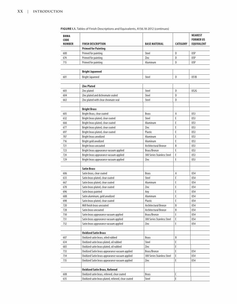
ANSI and the BHMA publish ANSI/BHMA A156.18 American National Standard for Materials and Fin-
ishes, 2006, and they refer to three finish designation systems: The National Bureau of Standards of the
U.S. Department of Commerce (U.S.), Canadian (C), and Builders Hardware Manufacturers Association
(BHMA). The BHMA finish designations give us more information in their number by not only telling
us what the finish of the item is, but also including the base metal that was used to manufacture the
product. This is important when specifying fire rated openings, so that we have a steel-based metal as
required by NFPA 80. Any other base metal, such as brass or bronze, would melt long before the time
required by code, leaving the door vulnerable to fire hazard.
For example, US26D is the U.S. designation for Satin Chromium Plated, while 626 is the BHMA desig-
nation for Satin Chromium Plated on Brass or Bronze base metal, and 652 is the BHMA designation
for Satin Chromium Plated on Steel base metal. This is important to know when specifying, ordering,
and installing hinges on fire rated doors, as they require steel-based hinges per NFPA 80 (see Stan-
dards—NFPA 80).
XX | INTRODUCTION
Trim: 215 x 276 mm cintro.indd 02/27/2015 03:42:48:PM Page XX
FIGURE I.1. Tables of Finish Descriptions and Equivalents, A156.18-2012 (continues)
BHMA CODE NUMBER FINSH DESCRIPTION BASE MATERIAL CATEGORY
NEAREST
FORMER US
EQUIVALENT
Primed for Painting
600 Primed for painting Steel D USP
674 Primed for painting Zinc D USP
715 Primed for painting Aluminum D USP
Bright Japanned
601 Bright Japanned Steel D US1B
Zinc Plated
603 Zinc plated Steel D US2G
604 Zinc plated and dichromate sealed Steel D
663 Zinc plated with clear chromate seal Steel D
Bright Brass
605 Bright Brass, clear coated Brass A US3
632 Bright brass plated, clear coated Steel E US3
666 Bright brass plated, clear coated Aluminum E US3
677 Bright brass plated, clear coated Zinc E US3
697 Bright brass plated, clear coated Plastic E US3
707 Bright brass anodized Aluminum E US3
716 Bright gold anodized Aluminum E US3
721 Bright brass uncoated Architectural Bronze B US3
723 Bright brass appearance vacuum applied Brass/Bronze E US3
724 Bright brass appearance vacuum applied 300 Series Stainless Steel E US3
729 Bright brass appearance vacuum applied Zinc E US3
Satin Brass
606 Satin brass, clear coated Brass A US4
633 Satin brass plated, clear coated Steel E US4
667 Satin brass plated, clear coated Aluminum E US4
678 Satin brass plated, clear coated Zinc E US4
696 Satin brass painted Any E US4
688 Satin aluminum, gold anodized Aluminum E US4
698 Satin brass plated, clear coated Plastic E US4
720 Mill finish brass uncoated Architectural Bronze B US4
728 Satin brass uncoated Architectural Bronze B US4
730 Satin brass appearance vacuum applied Brass/Bronze E US4
731 Satin brass appearance vacuum applied 300 Series Stainless Steel E US4
732 Satin brass appearance vacuum applied Zinc E US4
Oxidized Satin Brass
607 Oxidized satin brass, oiled rubbed Brass B
634 Oxidized satin brass plated, oil rubbed Steel E
683 Oxidized satin brass plated, oil rubbed Zinc E
733 Oxidized Satin brass appearance vacuum applied Brass/Bronze E US4
734 Oxidized Satin brass appearance vacuum applied 300 Series Stainless Steel E US4
735 Oxidized Satin brass appearance vacuum applied Zinc E US4
Oxidized Satin Brass, Relieved
608 Oxidized satin brass, relieved, clear coated Brass C
635 Oxidized satin brass plated, relieved, clear coated Steel E
INTRODUCTION | XXI
cintro.indd 02/27/2015 03:42:48:PM Page XXITrim: 215 x 276 mm
BHMA CODE NUMBER FINSH DESCRIPTION BASE MATERIAL CATEGORY
NEAREST
FORMER US
EQUIVALENT
Satin Brass, Blackened, Satin Relieved
609 Satin brass, blackened, satin relieved, clear coated Brass C US5
638 Satin brass plated, blackened, satin relieved, clear coated Steel E US5
Satin Brass, Blackened, Bright Relieved
610 Satin brass, blackened, bright relieved, clear coated Brass C US7
636 Satin brass plated, blackened bright relieved,
clear coated
Steel E US7
Bright Bronze
611 Bright bronze, clear coated Bronze A US9
637 Bright bronze plated, clear coated Steel E US9
679 Bright bronze plated, clear coated Zinc E US9
705 Bright bronze plated, clear coated Aluminum E US9
708 Bright bronze anodized Aluminum E US9
726 Bright bronze plated, clear coated Brass E US9
736 Bright bronze appearance vacuum applied Brass/Bronze E US9
737 Bright bronze appearance vacuum applied 300 Series Stainless Steel E US9
738 Bright bronze appearance vacuum applied Zinc E US9
Satin Bronze
612 Satin bronze, clear coated Bronze A US10
639 Satin bronze plated, clear coated Steel E US10
668 Satin bronze plated, clear coated Aluminum E US10
680 Satin bronze plated, clear coated Zinc E US10
694 Medium bronze painted Any A
699 Satin bronze plated, clear coated Plastic E US10
709 Satin bronze anodized Aluminum E US10
725 Satin bronze plated, clear coated Brass E US10
739 Satin bronze appearance vacuum applied Brass/Bronze E US10
740 Satin bronze appearance vacuum applied 300 Series Stainless Steel E US10
741 Satin bronze appearance vacuum applied Zinc E US10
Dark Oxidized Satin Bronze
613 Dark oxidized satin bronze, oil rubbed Bronze B US10B
640 Oxidized satin bronze plated over copper plate,
oil rubbed
Steel E US10B
695 Dark bronze painted Any A
703 Oxidized satin bronze plated, oil rubbed Aluminum E US10B
704 Oxidized satin bronze plated, oil rubbed Zinc E US10B
710 Dark oxidized satin bronze anodized Aluminum E US10B
727 Dark oxidized Satin bronze plated Brass E US10B
742 Dark oxidized Satin bronze appearance vacuum applied Brass/Bronze E US10B
743 Dark oxidized Satin bronze appearance vacuum applied 300 Series Stainless Steel E US10B
744 Dark oxidized Satin bronze appearance vacuum applied Zinc E US10B
Oxidized Satin Bronze, Relieved
614 Oxidized satin bronze, relieved clear coated Bronze C
615 Oxidized satin bronze, relieved, waxed Bronze C
641 Oxidized satin bronze plated, relieved, clear coated Steel E
642 Oxidized satin bronze plated, relieved, waxed Steel E
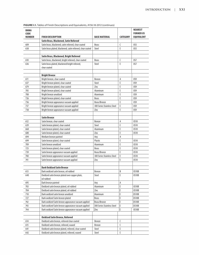
FIGURE I.1. Tables of Finish Descriptions and Equivalents, A156.18-2012 (continues)

XXII | INTRODUCTION
Trim: 215 x 276 mm cintro.indd 02/27/2015 03:42:48:PM Page XXII
BHMA CODE NUMBER FINSH DESCRIPTION BASE MATERIAL CATEGORY
NEAREST
FORMER US
EQUIVALENT
Satin Bronze, Blackened
616 Satin bronze, blackened, satin relieved, clear coated Bronze C US11
643 Satin bronze plated, blackened satin relieved, clear coated Steel E US11
Dark Oxidized Satin Bronze, Bright Relieved
617 Dark oxidized satin bronze, bright relieved, clear coated Bronze C US13
644 Dark oxidized satin bronze plated, bright relieved, clear
coated
Steel E US13
Bright Nickel
618 Bright nickel plated, clear coated Brass, Bronze A US14
645 Bright nickel plated, clear coated Steel E US14
669 Bright nickel plated Aluminum E US14
745 Bright nickel appearance vacuum applied Brass/Bronze E US14
746 Bright nickel appearance vacuum applied 300 Series Stainless Steel E US14
747 Bright nickel appearance vacuum applied Zinc E US14
Satin Nickel
619 Satin nickel plated, clear coated Brass, Bronze A US15
646 Satin nickel plated, clear coated Steel E US15
670 Satin nickel plated Aluminum E US15
748 Satin nickel appearance vacuum applied Brass/Bronze E US15
749 Satin nickel appearance vacuum applied 300 Series Stainless Steel E US15
750 Satin nickel appearance vacuum applied Zinc E US15
Satin Nickel Plated, Blackened
620 Satin nickel plated, blackened, satin relieved, clear coated Brass, Bronze C US15A
647 Satin nickel plated, blackened, satin relieved, clear coated Steel E US15A
Nickel Plated, Blackened, Relieved
621 Nickel plated, blackened, relieved clear coated Brass, Bronze C US17A
648 Nickel plated, blackened, relieved, clear coated Steel E US17A
Flat Black Coated
622 Flat black coated Brass, Bronze A US19
631 Flat black coated Steel E US19
671 Flat black coated Aluminum E US19
676 Flat black coated Zinc E US19
693 Black painted Any A
711 Flat black anodized Aluminum E US19
Light Oxidized Statuary Bronze
623 Light oxidized statuary bronze, clear coated Bronze C US20
649 Light oxidized bright (statuary?) bronze plated,
clear coated
Steel E US20
691 Light bronze painted Any E US20
Dark Oxidized Statuary Bronze Bronze C US20A
624 Dark oxidized statuary bronze, clear coated Bronze C US20
650 Dark oxidized statuary bronze plated, clear coated Steel E US20A
690 Dark bronze painted Any E US20A
FIGURE I.1. Tables of Finish Descriptions and Equivalents, A156.18-2012 (continues)
INTRODUCTION | XXIII
cintro.indd 02/27/2015 03:42:48:PM Page XXIIITrim: 215 x 276 mm
BHMA CODE NUMBER FINSH DESCRIPTION BASE MATERIAL CATEGORY
NEAREST
FORMER US
EQUIVALENT
Bright Chromium
625 Bright chromium plated over nickel Brass, Bronze A US26
651 Bright chromium plated over nickel Steel E US26
672 Bright chromium plated over nickel Aluminum E US26
681 Bright chromium plated over nickel Zinc E US26
700 Bright chromium plated over nickel Plastic E US26
712 Bright chromium anodized Aluminum E US26
717 Bright aluminum uncoated Aluminum B US26
Satin Chromium
626 Satin chromium plated over nickel Brass, Bronze A US26D
652 Satin chromium plated over nickel Steel E US26D
682 Satin chromium plated over nickel Zinc E US26D
701 Satin chromium plated over nickel Plastic E US26D
702 Satin chromium plated over nickel Aluminum E US26D
713 Satin chromium anodized Aluminum E US26D
Satin Aluminum
627 Satin aluminum, clear coated Aluminum A US27
628 Satin aluminum, clear anodized Aluminum A US28
673 Aluminum clear coated Aluminum D
689 Aluminum painted Any E US28
718 Satin aluminum uncoated Aluminum B US27
719 Mill finish aluminum uncoated Aluminum B US27
Bright Stainless Steel
629 Bright stainless steel Stainless steel
300 series
A US32
653 Bright stainless steel plated Stainless steel
400 series
E US32
Satin Stainless Steel
630 Satin stainless steel Stainless steel 300 series A US32D
654 Satin stainless steel plated Stainless steel 400 series E US32D
Other Combinations
655 Light oxidized satin bronze, bright relieved, clear coated Bronze C US13
656 Light oxidized satin bronze plated, bright relieved, clear
coated
Steel E US13
657 Dark oxidized copper plated, satin relieved, clear coated Steel C
658 Dark oxidized copper plated, bright relieved, clear coated Steel C
659 Light oxidized copper plated, satin relieved, clear coated Steel C
660 Light oxidized copper plated, bright relieved, clear coated Steel C
661 Oxidized satin copper plated, relieved, clear coated Steel C
662 Satin brass plated, browned satin relieved, clear coated Steel C
664 Cadmium plated with clear chromate seal Steel D
665 Cadmium plated with iridescent dichromate Steel D
675 Dichromate sealed Zinc D
684 Black chrome plated, bright Brass, Bronze C
685 Black chrome plated, satin Brass, Bronze C
686 Black chrome plated, bright Steel E
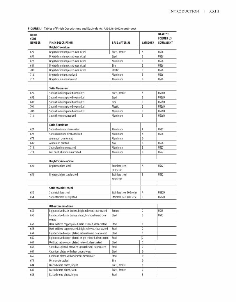
FIGURE I.1. Tables of Finish Descriptions and Equivalents, A156.18-2012 (continues)
XXIV | INTRODUCTION
Trim: 215 x 276 mm cintro.indd 02/27/2015 03:42:48:PM Page XXIV
BHMA CODE NUMBER FINSH DESCRIPTION BASE MATERIAL CATEGORY
NEAREST
FORMER US
EQUIVALENT
687 Black chrome plated, satin Steel E
692 Tan painted Any D
706 Gold painted Any D
714 White painted Aluminum D
722 Dark oxidized bronze oil rubbed Architectural Bronze B US10A
* Vacuum applied finishes are generally applied over stainless steel base, or a chrome substrate on various base materials
(Source: Copyright © 2012 by the Builders Hardware Manufacturers Association, Inc.)
GRADES
Most hardware devices are tested to meet multiple minimum criteria, and depending on the levels met,
grades are applied. Grade 1 is the best-performing device passing the highest minimum standards,
grade 2 is the next, and grade 3 is the lowest quality of the three.
Testing includes cycle testing, which is the performance of how many times a device can be “used.”
For example, one cycle of a test would include a lever handle of a lockset being rotated to retract
and extend a latchbolt. Another example is a door closer cycle; each time the door closer opens and
closes is one cycle. Other tests include impact, where the devices are struck; weather or salt tests,
where the devices are exposed to outdoor weather to see how long they will last, and the finish test
to see how long the architectural finish on the device will resist wear and the test of time.
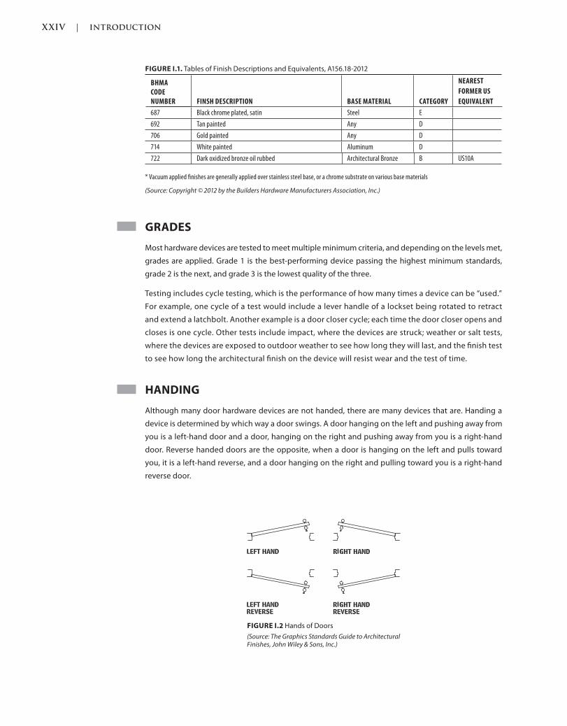
HANDING
Although many door hardware devices are not handed, there are many devices that are. Handing a
device is determined by which way a door swings. A door hanging on the left and pushing away from
you is a left-hand door and a door, hanging on the right and pushing away from you is a right-hand
door. Reverse handed doors are the opposite, when a door is hanging on the left and pulls toward
you, it is a left-hand reverse, and a door hanging on the right and pulling toward you is a right-hand
reverse door.
FIGURE I.1. Tables of Finish Descriptions and Equivalents, A156.18-2012
FIGURE I.2 Hands of Doors
(Source: The Graphics Standards Guide to Architectural Finishes, John Wiley & Sons, Inc.)

INTRODUCTION | XXV
cintro.indd 02/27/2015 03:42:48:PM Page XXVTrim: 215 x 276 mm
MATERIALS
CAST
A cast hardware device or component has typically been manufactured by melting metal or combina-
tions of metals to form a liquid, then pouring the liquid into a mold to create the device. Once the liquid
cools, it creates a new solid object.
FORGED
A forged hardware device or component has typically been manufactured similarly to a wrought device
by starting with a cast, then shaping the metal into either another object or a different shape than the
original. The difference between forged and wrought is that a wrought object is formed or rolled into
its new shape while a forged object is hammered into shape, which causes the steel to become harder
than wrought and less likely to crack when struck or striking another object. Forging can be done at dif-
ferent temperatures and is known by its type, for example, cold forging, warm forging, or hot forging.
STAMPED
A stamped hardware device or component has typically been manufactured by punching or stamping
an object, usually metal, in order to bend, remove, or emboss the original object into another object or
different shape than the original. The process might take place with one object or device or multiple
objects that are then attached to create the end result.
WROUGHT
A wrought hardware device or component has typically been manufactured similarly to a forged device
by starting with a cast, then shaping the metal into either another object or different shape from the
original. The difference between wrought and forged is the fact that forged is hammered into shape,
which causes the steel to become harder than wrought and less likely to crack when struck or striking
another object, while wrought is formed or rolled into its new shape.
FIRE RATING
LABELS
Doors and Frames are typically installed into walls of a structure. Depending on the structure’s type,
size, and occupancy, various fire rated walls are required to compartmentalize the structure so that fire
does not spread through the entire structure without some type of protection to stop it from spreading
from one area to another.
As such, doors, frames, and hardware must also carry a fire rating also known as a fire label. These rat-
ings are typically matched to the wall and ceiling ratings so that they have the same resistance as the
surrounding elements. Labels are different than listings; see Listings in this section.
Although doors must have a label to match a specific time frame as the walls do, such as a 3-hour or
45-minute rating, frames and hardware are required to be fire rated in general. Following are the most
common fire door ratings:
XXVI | INTRODUCTION
Trim: 215 x 276 mm cintro.indd 02/27/2015 03:42:48:PM Page XXVI
A
An “A” label door, also known as a three-hour (3-hour) rated door, has been tested to withstand a fire
from penetrating or moving from one side of the door to the other, if closed and latched properly, for a
minimum of three hours. As of today, only metal doors can be manufactured to meet this rating.
B
A “B” label door, also known as a one-and-a-half hour (1-1/2-hour) rated door has been tested to keep a
fire from penetrating or moving from one side of the door to the other, if closed and latched properly,
for a minimum of one-and-one-half hours.
C
A “C” label door, also known as a 45-minute rated door, has been tested to keep a fire from penetrating
or moving from one side of the door to the other, if closed and latched properly, for a minimum of 45
minutes.
20 Minute
Twenty-minute (20-minute) doors were most typically used in corridors of educational facilities, but in
current construction of these types of facilities, at a minimum 45-minute-rated doors are more typically
required.
Smoke
Some fire rated doors require a Smoke (S) rating in addition or in lieu of a fire rating, depending on the
construction, facility, and code type. This type of opening would prohibit or limit the amount of smoke
being transferred from one side of the opening to the other.
LISTING
A hardware device most typically has a listing, which is usually governed and applied by the Under-
writers Laboratories (UL), (see UL under Standards earlier in this Introduction.) The listing requires cer-
tain devices to operate in a certain manner for certain applications; one example is panic hardware on
egress doors being required in places of occupancy by more than 50 people at a time.
SPECIFICATIONS
Specifications can be written many different ways using many different methods, and there can be
many right answers. Following are some specification types, methods, and mediums by which a proj-
ect can be specified.
FORMATS
The Construction Specifications Institute (CSI) developed and continues to maintain various docu-
mentation standards that are used by the architect to create project specification documents to com-
plement the drawings or visual representation of the drawings. A typical specification is created in
three-part format, either in MasterFormat® 95 or 2004, and can be written as proprietary, open, or ANSI,
and in a 2D or 3D medium.

INTRODUCTION | XXVII
cintro.indd 02/27/2015 03:42:48:PM Page XXVIITrim: 215 x 276 mm
PageFormat
PageFormat is a standard arrangement of information through consistent numbering in each division,
in each section, and on each page of a specification manual. For example, each section starts with PART
1—GENERAL, 1.1 Summary, A. Section Includes or relevant instructions, and ends with PART 2—EXECU-
TION, 3.3 Adjusting or the relevant instructions.
MasterFormat®
MasterFormat® is a standard that uses a unique numbering system to organize information for build-
ing projects. This format went through a major update in 2004, referred to as MasterFormat® 2004, and
receives updates every couple of years. Although created long before with many updates since, the
version prior to 2004 is typically referred to as MasterFormat® 95.
95
MasterFormat® 95 is a 16 Division format with five-number sections. For example, door hardware is
located in Division 8, Section 08700, and is named Hardware. Within this division and section, there
are other formats used to create consistent page layout and references, known as OmniClass™,
PageFormat.
2004
MasterFormat® 2004 is a 50-division format with six-number sections. For example, door hardware is
located in Division 08, Section 08 71 00, and is named Door Hardware. Within this division and section,
there are other formats used to create consistent page layout and references, known as OmniClass™,
PageFormat. MasterFormat® 2004 allows for all of the technological and product advancements made
over the years, and now has a place for them to be specified, whereas in the older versions some of
these newer products had to be specified in sections where they did not belong, or in what was known
as the Phantom Division 17, which was created randomly by various firms or entities to have a place for
items that did not have a place of their own.
Three Parts
Each specification document section typically has three parts in order to categorize the data consis-
tently throughout the project specification documents; this way the data is in the same area each time
you look, no matter what type of product or process you are looking at. Specifications for any products
or processes should be specified once, in one place, and should be clear, correct, concise, and complete.
Repetition can lead to conflicts, varying interpretations, and errors.
PART 1
Part 1 General typically describes the general requirements of a project, including the procedures,
administration, and any requirements specific to the section written. Part 1 also typically refers back to
and clarifies any Division 01 requirements such as substitution requests.
PART 2
Part 2 Products typically describes the products, including any materials and equipment that is required
for the project. Part 2 also typically describes any specific manufacturers, product numbers, finishes,
and functions required for the project as a whole or specific to an opening type. Most product types
require at least three equal products of the same type, grade, and function specified to allow for com-
petitive bidding and the best value for the owner.
XXVIII | INTRODUCTION
Trim: 215 x 276 mm cintro.indd 02/27/2015 03:42:48:PM Page XXVIII
PART 3
Part 3 Execution typically describes the various applications and installations, including any pre- or
postconstruction cleaning, protection, and anything to do with onsite fabrication.
UniFormat™
UniFormat™ is a classification system for organizing construction information during the preliminary
stages of design. By starting out with a standard format, it is easier and more intuitive to create the
construction specifications from this early project document.
MEDIA
Door hardware specifications can be written in various media, but the most prominent approaches are
2D or 3D.
2D
2D specifications are written conventionally in some type of word processor format. This can be done
“long hand” in a word processing program or via door hardware specification or submittal-writing soft-
ware that exports the data to a 2D word processing document.
3D
3D specification is a newer medium to create the information required. This information is an add-
on to the overall design software and allows the 3D data, known as door libraries, to be exported
out of the 3D software and models. Once the data is extracted, it can be manipulated, incorporated
with details and data specific to that project, opening, function, and surrounding conditions, and
then be imported back into the 3D environment or model as one of the contributing objects to the
whole.
TYPES
Descriptive
Descriptive specifications are written as a detailed description of the requirements of the specific type
of hardware. This includes the material, function, finish, and application. Descriptive specifications do
not use manufacturers’ names or model numbers.
Nonrestrictive
Nonrestrictive specifications are written specifically to prohibit proprietary specifications and to allow
competitive bidding and the best value for the owner’s money. Nonrestrictive specifications can be
written in descriptive, performance, or reference standard format, as long as more than one manufac-
turer can meet those requirements.
Performance
Performance specifications are written as a detailed requirement of the end results without specific
material and processes being described. This allows for any methods or means as long as the required
end results are achieved. This can be both good and risky, and new types of products or means might
be created to achieve these results, giving something new and not seen or used before. At the same
INTRODUCTION | XXIX
cintro.indd 02/27/2015 03:42:48:PM Page XXIXTrim: 215 x 276 mm
time, employing something not used before means it has no track record of performance, just the test-
ing required to meet the standards specified.
Proprietary
Proprietary specifications are written with a specific manufacturer, brand, and model number without
any other manufacturers or products allowed. This might be the case when an existing facility, say a
healthcare campus, has their standards, stock of the components for any nonfunctioning hardware,
and the training to fix it. This makes it easier than starting a new wing of a hospital with brand-new
hardware manufacturers and types of hardware to learn and maintain. Proprietary specifications and
projects are typically only allowed when the money or owner funding the project is private and not
public. By specifying proprietary items, the owner will likely pay more for the items as there is no com-
petition during the bidding stage—the hardware required is single source, so the supplier can charge
a bit more than for something being competitively bid.
Reference Standard
Reference standard specifications are written with a specific type or function in mind, but not neces-
sarily a specific aesthetic or manufacturer. Door hardware reference standard specifications would be
written around American National Standard Institute/Builders Hardware Manufacturer’s Association
(ANSI/BHMA) standards.
STANDARDS
A standard is enforceable when an Authority Having Jurisdiction (AHJ), a local, federal, or other entity
having jurisdiction over law, adopts the standard as a whole itself, or references the standard in another
adopted law, such as a state building code. The most commonly referenced standard in just about
every building code is National Fire Protection Association (NFPA) 80, Standard for Fire Doors and Other
Opening Protectives, 2010, or the most current version (see Standards, Fire/Smoke). Some standards are
updated on a consistent cycle, typically every three years (NFPA 80, 2007, was the version prior to 2010
and 2013 will be the next version).
Standards are typically referred to as the minimum standard and are not always that impressive when
it comes to cycle, grade, or any other minimum requirement. That said, although there are minimum
standards, there are some manufacturers, products, and solutions that go above and beyond these
minimums, some at the same or minimal additional cost, so do your research and rely on true consul-
tants who can offer opinions on any and all products and solutions. These types of products not only
offer better value for cost, but also offer other positive aspects to the owner and environment by being
a sustainable solution, for example, having to replace a mortise lock after 15 million cycles instead of
the typical minimum standard of 1 million, which both meet the minimum standard.
ACCESSIBILITY
The Americans with Disabilities Act (ADA) was created to set guidelines for accessibility to places of
public accommodation and commercial facilities by individuals with disabilities. These guidelines are to
be applied during the design, construction, and alteration of such buildings and facilities to the extent
required by regulations issued by federal agencies, including the Department of Justice, under the
Americans with Disabilities Act of 1990.
XXX | INTRODUCTION
Trim: 215 x 276 mm cintro.indd 02/27/2015 03:42:48:PM Page XXX
ADAAG—The Americans with Disabilities Act Accessibility Guidelines
The Americans with Disabilities Act (ADA) is a landmark law that protects the civil rights of persons with
disabilities. ADAAG serves as the basis for standards used to enforce the design requirements of the
ADA. These standards are maintained by the U.S. Department of Justice (DOJ) and the U.S. Department
of Transportation (DOT).
ICC/A117.1 Accessible and Usable Buildings and Facilities
ICC/A117.1 is available for adoption and use by jurisdictions internationally. Its use within a government
jurisdiction is intended to be accomplished through adoption by reference in accordance with pro-
ceedings establishing the jurisdiction’s laws.
International Green Construction Code (IGCC)
The International Green Construction Code (IGCC) is published by the International Code Council (ICC),
which was formed in 1994 as a nonprofit organization dedicated to developing a single set of com-
prehensive and coordinated national model construction codes. The ICC was a combination of the
Building Officials and Code Administrators International, Inc. (BOCA), the International Conference of
Building Officials (ICBO), and the Southern Building Code Congress International, Inc. (SBCCI).
NFPA 1, Fire Code
Although NFPA created and maintains their own fire code, it is not widely used or adopted, where the
preferred code is from the International Code Council (ICC).
NFPA 70, National Electric Code
Adopted in all 50 states, NFPA 70 is the standard for safe electrical design, installation, and inspection
to protect people and property from electrical hazards. Please refer to the most recent version of NFPA
70 for current and complete information.
NFPA 80, Standard for Fire Doors and Other Opening Protectives
NFPA 80 regulates the installation and maintenance of assemblies and devices used to protect open-
ings in walls, floors, and ceilings against the spread of fire and smoke within, into, or out of buildings.
Please refer to the most recent version of NFPA 80 for current and complete information.
ASTM INTERNATIONAL
(Formerly Known as the American Society for Testing and Materials)
A globally recognized leader in the development and delivery of international voluntary consensus
standards that works in an open and transparent process and using ASTM’s advanced electronic infra-
structure, ASTM members deliver the test methods, specifications, guidelines, and practices that sup-
port industries and governments worldwide.
UNDERWRITERS LABORATORY UL
Underwriters Laboratory (UL) is an independent safety company innovating solutions for many of the
items that we use every day, from electricity to sustainability and renewable energy. UL is dedicated
to testing safe environments to help safeguard people. There are many UL standards that affect doors
and door hardware.
INTRODUCTION | XXXI
cintro.indd 02/27/2015 03:42:48:PM Page XXXITrim: 215 x 276 mm
SUBMITTALS
Hardware schedules, also known as submittals, are typically created from architectural project speci-
fications and drawings, which are created by an architect. Hardware schedules are created from the
specifications typically by a door and hardware distributor employee. The schedule is typically submit-
ted to the project general contractor or construction manager, who submits it to the project architect
for approval prior to ordering and delivering to the jobsite.
While a vertical schedule is typically specified and preferred by an architect, this standard describes
both horizontal and vertical formats. Project specifications typically specify that hardware schedules
are required to be created by a certified Architectural Hardware Consultant (AHC), who is certified
by DHI.
SUBSTITUTIONS
If product substitution requests are allowed from what was originally specified, the request process
is typically specified in Division 01 of the project manual, otherwise known as the specifications. The
substitution request requirements are typically asking for product data and proof that the requested
substitution will meet the same grade, function, application, aesthetic, and quality of the originally
specified product. It is recommended that all substitution requests be submitted within the procedures
as outlined in Division 1, Section 01 25 13 Product Substitution, and on Construction Specifications
Institute (CSI) Substitution Request Forms.
As mentioned in the Standards section earlier in this Introduction, be cautious of what is considered an
equal as standards refer to the minimum standard, but there are some manufacturers, products, and
solutions that go above and beyond these minimums.
It is recommended that substitution requests and approvals not be taken lightly as sometimes the
substitution is proposed or taking place to strictly save money or to become more competitive on a bid
to win the project contract to supply the door hardware. Although it is not always the case where you
get what you pay for, it is typically the case with door hardware. If you are saving money on an item,
it is likely that the item is not of the same standards and quality as the originally specified device. The
quality substitution can be one of a few types, for example, furnishing a hinge with a cheaper-quality
finish or rough edges as compared to a better-quality finish and square flush edges.
SUSTAINABILITY
Some manufacturers contribute to sustainability with the way they source materials, manufacture
products, and run and maintain factories and offices. There are new practices taking place known as
Health Product Declarations (HPD) and Environmental Product Declarations (EPD). These new practices
provide transparent information about products, which include their materials and effects on the living
beings who are in contact with the items. HPDs and EPDs are almost like the cereal box labels that list
the ingredients of products and their health effects. A life-cycle analysis is also becoming a common
practice, giving the product an expected lifespan of use.

1
c01.indd Page 1 03/02/2015 09:18:52:PM
As discussed in the Introduction, the first type of device addressed in the Door and Hardware
Institute’s Sequence and Format for the Hardware Schedule is the hanging device. Although not
typically a highlight of the door opening, the hanging device is one of the most important components.
Supporting the entire weight of the door from the top, bottom, side, or a combination, the hanging
device is relied on for its precise and consistent pivot point swing or slide, and is probably the most
actively used door opening component.
Depending on the type of door, its function, and application, doors can be hung onto a door frame,
onto a framed opening, or directly on a wall. A swinging door can be hung on hinges, continuous
hinges, pivots, or floor closers, while a sliding door can be hung on tracks and hangers suspended from
the top underneath the head of a framed opening, on the face of the wall, or supported by the floor
from underneath the door. The most efficient and effective way to hang a door would be any means
supported by the floor rather than the frame or wall. This creates less or no tension on the frame or wall
where the door by nature is pulling away, whereas a door supported by the floor is resting on top and
has no tension at all.
Although a swinging door is the most common type, sliding door options and use have increased over
recent years because of their functionality, space-saving ability, and aesthetics.
HINGES
Also Known As: Butts, Butt Hinges, Standard Hinges
DESCRIPTION
Hinges are manufactured to accommodate various door sizes, thicknesses, weights, new and existing
conditions, and fire ratings. Special hinge applications are available for specific situations, which
include healthcare and those that have particular aesthetic needs, sound requirements, or door and
frame applied materials.
Hanging Devices
1
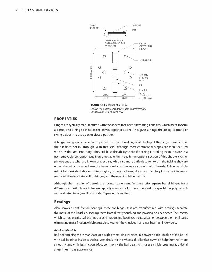
2 | HANGING DEVICES
c01.indd Page 2 03/02/2015 09:18:52:PM
FIGURE 1.1 Elements of a Hinge
(Source: The Graphic Standards Guide to Architectural Finishes, John Wiley & Sons, Inc.)
PROPERTIES
Hinges are typically manufactured with two leaves that have alternating knuckles, which meet to form
a barrel, and a hinge pin holds the leaves together as one. This gives a hinge the ability to rotate or
swing a door into the open or closed position.
A hinge pin typically has a flat tipped end so that it rests against the top of the hinge barrel so that
the pin does not fall through. With that said, although most commercial hinges are manufactured
with pins that are “nonrising,” they still have the ability to rise if nothing is holding them in place as a
nonremovable pin option (see Nonremovable Pin in the hinge options section of this chapter). Other
pin options are what are known as fast pins, which are more difficult to remove in the field as they are
either riveted or threaded into the barrel, similar to the way a screw is with threads. This type of pin
might be most desirable on out-swinging, or reverse bevel, doors so that the pins cannot be easily
removed, the door taken off its hinges, and the opening left unsecure.
Although the majority of barrels are round, some manufacturers offer square barrel hinges for a
different aesthetic. Screw holes are typically countersunk, unless one is using a special hinge type such
as the slip-in hinge (see Slip-In under Types in this section).
Bearings
Also known as anti-friction bearings, these are hinges that are manufactured with bearings separate
the metal of the knuckles, keeping them from directly touching and pivoting on each other. The inserts,
which can be plastic, ball bearings or oil-impregnated bearings, create a barrier between the metal parts,
eliminating metal friction, which causes less wear on the knuckles than a nonbearing hinge would.
BALL BEARING
Ball bearing hinges are manufactured with a metal ring inserted in between each knuckle of the barrel
with ball bearings inside each ring, very similar to the wheels of roller skates, which help them roll more
smoothly and with less friction. Most commonly, the ball bearing rings are visible, creating additional
shear lines in the appearance.
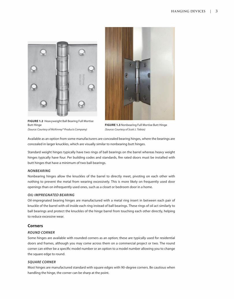
HANGING DEVICES | 3
c01.indd Page 3 03/02/2015 09:18:52:PM
Available as an option from some manufacturers are concealed bearing hinges, where the bearings are
concealed in larger knuckles, which are visually similar to nonbearing butt hinges.
Standard weight hinges typically have two rings of ball bearings on the barrel whereas heavy weight
hinges typically have four. Per building codes and standards, fire rated doors must be installed with
butt hinges that have a minimum of two ball bearings.
NONBEARING
Nonbearing hinges allow the knuckles of the barrel to directly meet, pivoting on each other with
nothing to prevent the metal from wearing excessively. This is more likely on frequently used door
openings than on infrequently used ones, such as a closet or bedroom door in a home.
OILIMPREGNATED BEARING
Oil-impregnated bearing hinges are manufactured with a metal ring insert in between each pair of
knuckle of the barrel with oil inside each ring instead of ball bearings. These rings of oil act similarly to
ball bearings and protect the knuckles of the hinge barrel from touching each other directly, helping
to reduce excessive wear.
Corners
ROUND CORNER
Some hinges are available with rounded corners as an option; these are typically used for residential
doors and frames, although you may come across them on a commercial project or two. The round
corner can either be a specific model number or an option to a model number allowing you to change
the square edge to round.
SQUARE CORNER
Most hinges are manufactured standard with square edges with 90-degree corners. Be cautious when
handling the hinge, the corner can be sharp at the point.
FIGURE 1.2 Heavyweight Ball Bearing Full Mortise
Butt Hinge
(Source: Courtesy of McKinney® Products Company)
FIGURE 1.3 Nonbearing Full Mortise Butt Hinge
(Source: Courtesy of Scott J. Tobias)
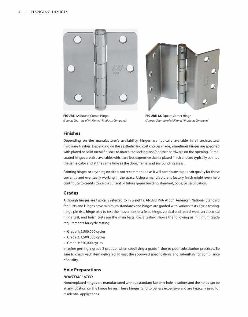
4 | HANGING DEVICES
c01.indd Page 4 03/02/2015 09:18:52:PM
Finishes
Depending on the manufacturer’s availability, hinges are typically available in all architectural
hardware finishes. Depending on the aesthetic and cost choices made, sometimes hinges are specified
with plated or solid metal finishes to match the locking and/or other hardware on the opening. Prime-
coated hinges are also available, which are less expensive than a plated finish and are typically painted
the same color and at the same time as the door, frame, and surrounding areas.
Painting hinges or anything on site is not recommended as it will contribute to poor air quality for those
currently and eventually working in the space. Using a manufacturer’s factory finish might even help
contribute to credits toward a current or future green building standard, code, or certification.
Grades
Although hinges are typically referred to in weights, ANSI/BHMA A156.1 American National Standard
for Butts and Hinges have minimum standards and hinges are graded with various tests. Cycle testing,
hinge pin rise, hinge play to test the movement of a fixed hinge, vertical and lateral wear, an electrical
hinge test, and finish tests are the main tests. Cycle testing shows the following as minimum grade
requirements for cycle testing:
Grade 1: 2,500,000 cycles
Grade 2: 1,500,000 cycles
Grade 3: 350,000 cycles
Imagine getting a grade 3 product when specifying a grade 1 due to poor substitution practices. Be
sure to check each item delivered against the approved specifications and submittals for compliance
of quality.
Hole Preparations
NONTEMPLATED
Nontemplated hinges are manufactured without standard fastener hole locations and the holes can be
at any location on the hinge leaves. These hinges tend to be less expensive and are typically used for
residential applications.
FIGURE 1.4 Round Corner Hinge
(Source: Courtesy of McKinney® Products Company)
FIGURE 1.5 Square Corner Hinge
(Source: Courtesy of McKinney® Products Company)
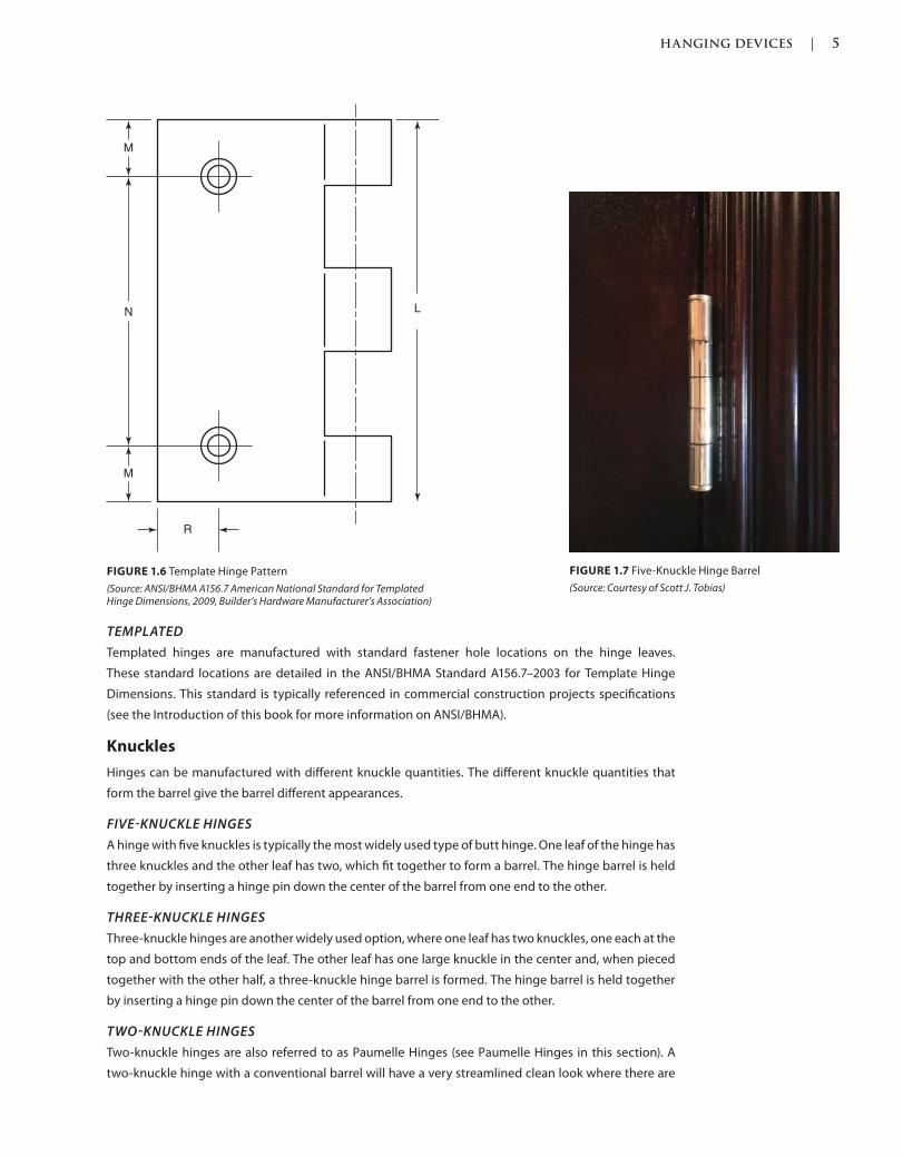
HANGING DEVICES | 5
c01.indd Page 5 03/02/2015 09:18:52:PM
TEMPLATED
Templated hinges are manufactured with standard fastener hole locations on the hinge leaves.
These standard locations are detailed in the ANSI/BHMA Standard A156.7–2003 for Template Hinge
Dimensions. This standard is typically referenced in commercial construction projects specifications
(see the Introduction of this book for more information on ANSI/BHMA).
Knuckles
Hinges can be manufactured with different knuckle quantities. The different knuckle quantities that
form the barrel give the barrel different appearances.
FIVEKNUCKLE HINGES
A hinge with five knuckles is typically the most widely used type of butt hinge. One leaf of the hinge has
three knuckles and the other leaf has two, which fit together to form a barrel. The hinge barrel is held
together by inserting a hinge pin down the center of the barrel from one end to the other.
THREEKNUCKLE HINGES
Three-knuckle hinges are another widely used option, where one leaf has two knuckles, one each at the
top and bottom ends of the leaf. The other leaf has one large knuckle in the center and, when pieced
together with the other half, a three-knuckle hinge barrel is formed. The hinge barrel is held together
by inserting a hinge pin down the center of the barrel from one end to the other.
TWOKNUCKLE HINGES
Two-knuckle hinges are also referred to as Paumelle Hinges (see Paumelle Hinges in this section). A
two-knuckle hinge with a conventional barrel will have a very streamlined clean look where there are
FIGURE 1.6 Template Hinge Pattern
(Source: ANSI/BHMA A156.7 American National Standard for Templated Hinge Dimensions, 2009, Builder’s Hardware Manufacturer’s Association)
L
M
N
M
R
FIGURE 1.7 Five-Knuckle Hinge Barrel
(Source: Courtesy of Scott J. Tobias)
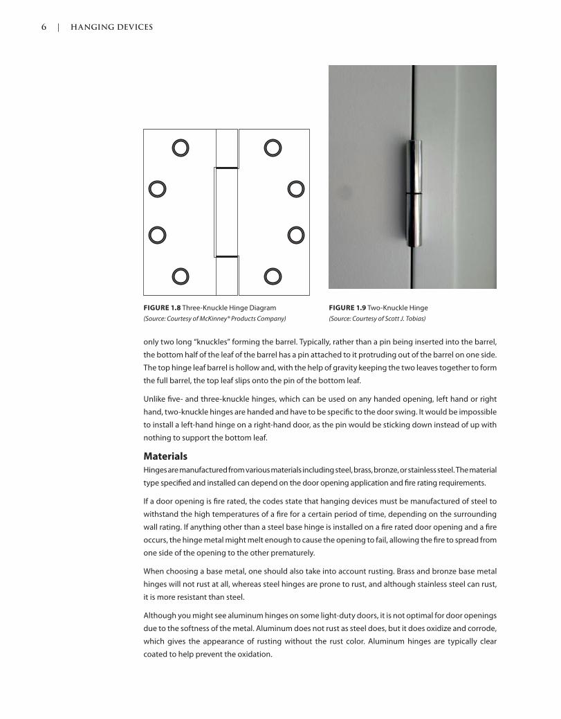
6 | HANGING DEVICES
c01.indd Page 6 03/02/2015 09:18:52:PM
only two long “knuckles” forming the barrel. Typically, rather than a pin being inserted into the barrel,
the bottom half of the leaf of the barrel has a pin attached to it protruding out of the barrel on one side.
The top hinge leaf barrel is hollow and, with the help of gravity keeping the two leaves together to form
the full barrel, the top leaf slips onto the pin of the bottom leaf.
Unlike five- and three-knuckle hinges, which can be used on any handed opening, left hand or right
hand, two-knuckle hinges are handed and have to be specific to the door swing. It would be impossible
to install a left-hand hinge on a right-hand door, as the pin would be sticking down instead of up with
nothing to support the bottom leaf.
Materials
Hinges are manufactured from various materials including steel, brass, bronze, or stainless steel. The material
type specified and installed can depend on the door opening application and fire rating requirements.
If a door opening is fire rated, the codes state that hanging devices must be manufactured of steel to
withstand the high temperatures of a fire for a certain period of time, depending on the surrounding
wall rating. If anything other than a steel base hinge is installed on a fire rated door opening and a fire
occurs, the hinge metal might melt enough to cause the opening to fail, allowing the fire to spread from
one side of the opening to the other prematurely.
When choosing a base metal, one should also take into account rusting. Brass and bronze base metal
hinges will not rust at all, whereas steel hinges are prone to rust, and although stainless steel can rust,
it is more resistant than steel.
Although you might see aluminum hinges on some light-duty doors, it is not optimal for door openings
due to the softness of the metal. Aluminum does not rust as steel does, but it does oxidize and corrode,
which gives the appearance of rusting without the rust color. Aluminum hinges are typically clear
coated to help prevent the oxidation.
FIGURE 1.8 Three-Knuckle Hinge Diagram
(Source: Courtesy of McKinney® Products Company)
FIGURE 1.9 Two-Knuckle Hinge
(Source: Courtesy of Scott J. Tobias)
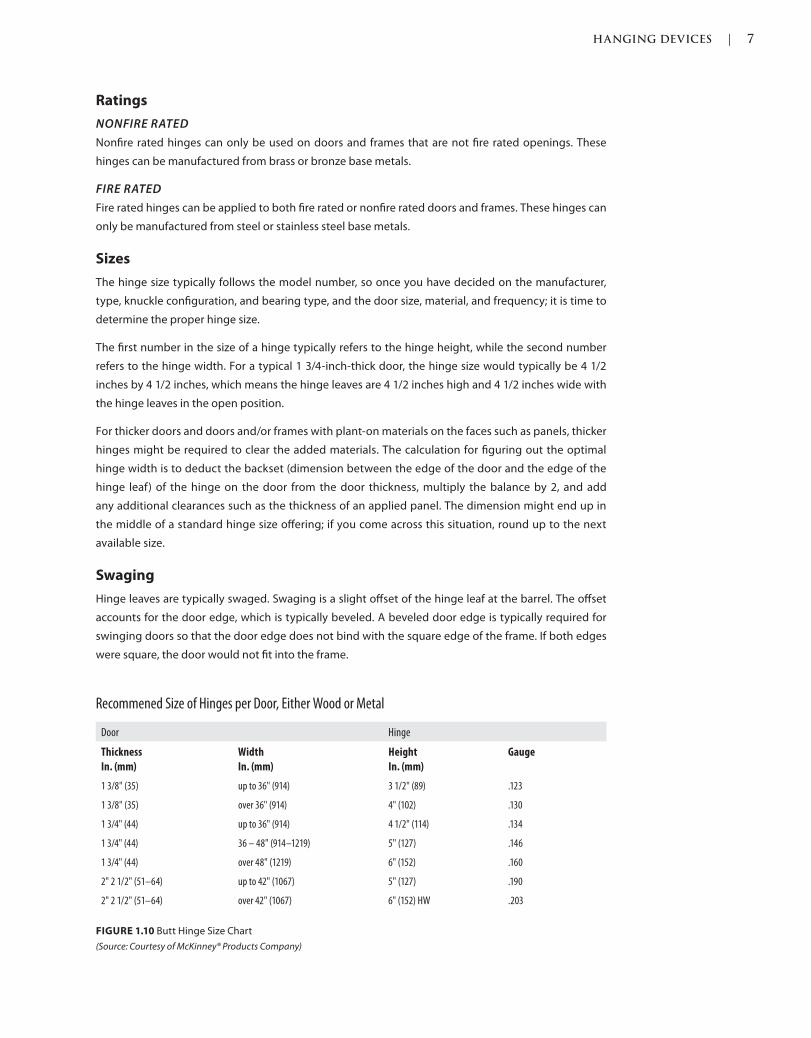
HANGING DEVICES | 7
c01.indd Page 7 03/02/2015 09:18:52:PM
Ratings
NONFIRE RATED
Nonfire rated hinges can only be used on doors and frames that are not fire rated openings. These
hinges can be manufactured from brass or bronze base metals.
FIRE RATED
Fire rated hinges can be applied to both fire rated or nonfire rated doors and frames. These hinges can
only be manufactured from steel or stainless steel base metals.
Sizes
The hinge size typically follows the model number, so once you have decided on the manufacturer,
type, knuckle configuration, and bearing type, and the door size, material, and frequency; it is time to
determine the proper hinge size.
The first number in the size of a hinge typically refers to the hinge height, while the second number
refers to the hinge width. For a typical 1 3/4-inch-thick door, the hinge size would typically be 4 1/2
inches by 4 1/2 inches, which means the hinge leaves are 4 1/2 inches high and 4 1/2 inches wide with
the hinge leaves in the open position.
For thicker doors and doors and/or frames with plant-on materials on the faces such as panels, thicker
hinges might be required to clear the added materials. The calculation for figuring out the optimal
hinge width is to deduct the backset (dimension between the edge of the door and the edge of the
hinge leaf) of the hinge on the door from the door thickness, multiply the balance by 2, and add
any additional clearances such as the thickness of an applied panel. The dimension might end up in
the middle of a standard hinge size offering; if you come across this situation, round up to the next
available size.
Swaging
Hinge leaves are typically swaged. Swaging is a slight offset of the hinge leaf at the barrel. The offset
accounts for the door edge, which is typically beveled. A beveled door edge is typically required for
swinging doors so that the door edge does not bind with the square edge of the frame. If both edges
were square, the door would not fit into the frame.
FIGURE 1.10 Butt Hinge Size Chart
(Source: Courtesy of McKinney® Products Company)
Recommened Size of Hinges per Door, Either Wood or Metal
Door Hinge
Thickness
In. (mm)
Width
In. (mm)
Height
In. (mm)
Gauge
1 3/8" (35) up to 36" (914) 3 1/2" (89) .123
1 3/8" (35) over 36" (914) 4" (102) .130
1 3/4" (44) up to 36" (914) 4 1/2" (114) .134
1 3/4" (44) 36 – 48" (914–1219) 5" (127) .146
1 3/4" (44) over 48" (1219) 6" (152) .160
2" 2 1/2" (51–64) up to 42" (1067) 5" (127) .190
2" 2 1/2" (51–64) over 42" (1067) 6" (152) HW .203
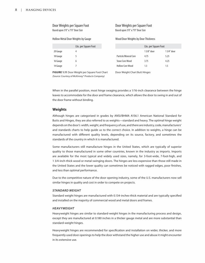
8 | HANGING DEVICES
c01.indd Page 8 03/02/2015 09:18:52:PM
When in the parallel position, most hinge swaging provides a 1/16-inch clearance between the hinge
leaves to accommodate for the door and frame clearance, which allows the door to swing in and out of
the door frame without binding.
Weights
Although hinges are categorized in grades by ANSI/BHMA A156.1 American National Standard for
Butts and Hinges, they are also referred to as weights—standard and heavy. The optimal hinge weight
depends on the door’s width, weight, and frequency of use, and there are industry, code, manufacturers’
and standards charts to help guide us to the correct choice. In addition to weights, a hinge can be
manufactured with different quality levels, depending on its source, factory, and sometimes the
standards of the country in which it is manufactured.
Some manufacturers still manufacture hinges in the United States, which are typically of superior
quality to those manufactured in some other countries, known in the industry as imports. Imports
are available for the most typical and widely used sizes, namely, for 3-foot-wide, 7-foot-high, and
1 3/4-inch-thick wood or metal swinging doors. The hinges are less expensive than those still made in
the United States and the lower quality can sometimes be noticed with ragged edges, poor finishes,
and less than optimal performance.
Due to the competitive nature of the door opening industry, some of the U.S. manufacturers now sell
similar hinges in quality and cost in order to compete on projects.
STANDARD WEIGHT
Standard weight hinges are manufactured with 0.134-inches-thick material and are typically specified
and installed on the majority of commercial wood and metal doors and frames.
HEAVYWEIGHT
Heavyweight hinges are similar to standard-weight hinges in the manufacturing process and design,
except they are manufactured at 0.180 inches in a thicker gauge metal and are more substantial than
standard-weight hinges.
Heavyweight hinges are recommended for specification and installation on wider, thicker, and more
frequently used door openings to help the door withstand the higher use and abuse it might encounter
in its extensive use.
FIGURE 1.11 Door Weight per Square Foot Chart Door Weight Chart Butt Hinges
(Source: Courtesy of McKinney® Products Company)
Door Weights per Square FootBased upon 3'0" x 7'0" Door Size
Hollow Metal Door Weights by Gauge
Lbs. per Square Foot
20 Gauge 4
18 Gauge 5
16 Gauge 6
14 Gauge 7
Door Weights per Square FootBased upon 3'0" x 7'0" Door Size
Wood Door Weights by Door Thickness
Lbs. per Square Foot
1 3/8" door 1 3/4" door
Particle/Mineral Core 4.75 5.25
Stave Core Wood 3.75 4.25
Hollow Core Wood 1.3 1.5
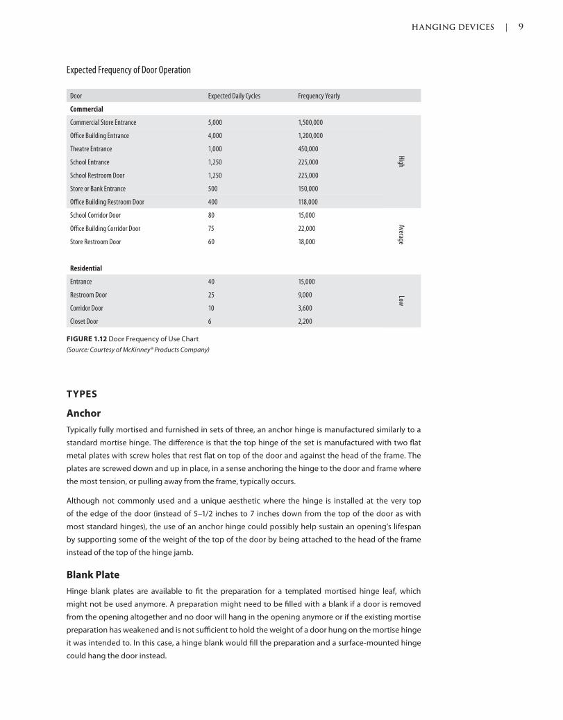
HANGING DEVICES | 9
c01.indd Page 9 03/02/2015 09:18:52:PM
TYPES
Anchor
Typically fully mortised and furnished in sets of three, an anchor hinge is manufactured similarly to a
standard mortise hinge. The difference is that the top hinge of the set is manufactured with two flat
metal plates with screw holes that rest flat on top of the door and against the head of the frame. The
plates are screwed down and up in place, in a sense anchoring the hinge to the door and frame where
the most tension, or pulling away from the frame, typically occurs.
Although not commonly used and a unique aesthetic where the hinge is installed at the very top
of the edge of the door (instead of 5–1/2 inches to 7 inches down from the top of the door as with
most standard hinges), the use of an anchor hinge could possibly help sustain an opening’s lifespan
by supporting some of the weight of the top of the door by being attached to the head of the frame
instead of the top of the hinge jamb.
Blank Plate
Hinge blank plates are available to fit the preparation for a templated mortised hinge leaf, which
might not be used anymore. A preparation might need to be filled with a blank if a door is removed
from the opening altogether and no door will hang in the opening anymore or if the existing mortise
preparation has weakened and is not sufficient to hold the weight of a door hung on the mortise hinge
it was intended to. In this case, a hinge blank would fill the preparation and a surface-mounted hinge
could hang the door instead.
Expected Frequency of Door Operation
Door Expected Daily Cycles Frequency Yearly
Commercial
Commercial Store Entrance 5,000 1,500,000
High
Office Building Entrance 4,000 1,200,000
Theatre Entrance 1,000 450,000
School Entrance 1,250 225,000
School Restroom Door 1,250 225,000
Store or Bank Entrance 500 150,000
Office Building Restroom Door 400 118,000
School Corridor Door 80 15,000
Average
Office Building Corridor Door 75 22,000
Store Restroom Door 60 18,000
Residential
Entrance 40 15,000
Low
Restroom Door 25 9,000
Corridor Door 10 3,600
Closet Door 6 2,200
FIGURE 1.12 Door Frequency of Use Chart
(Source: Courtesy of McKinney® Products Company)
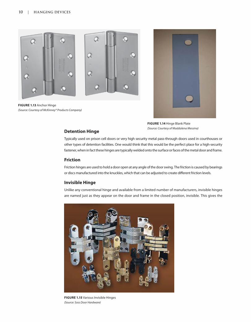
10 | HANGING DEVICES
c01.indd Page 10 03/02/2015 09:18:52:PM
Detention Hinge
Typically used on prison cell doors or very high security metal pass-through doors used in courthouses or
other types of detention facilities. One would think that this would be the perfect place for a high-security
fastener, when in fact these hinges are typically welded onto the surface or faces of the metal door and frame.
Friction
Friction hinges are used to hold a door open at any angle of the door swing. The friction is caused by bearings
or discs manufactured into the knuckles, which that can be adjusted to create different friction levels.
Invisible Hinge
Unlike any conventional hinge and available from a limited number of manufacturers, invisible hinges
are named just as they appear on the door and frame in the closed position, invisible. This gives the
FIGURE 1.14 Hinge Blank Plate
(Source: Courtesy of Maddalena Messina)
FIGURE 1.13 Anchor Hinge
(Source: Courtesy of McKinney® Products Company)
FIGURE 1.15 Various Invisible Hinges
(Source: Soss Door Hardware)
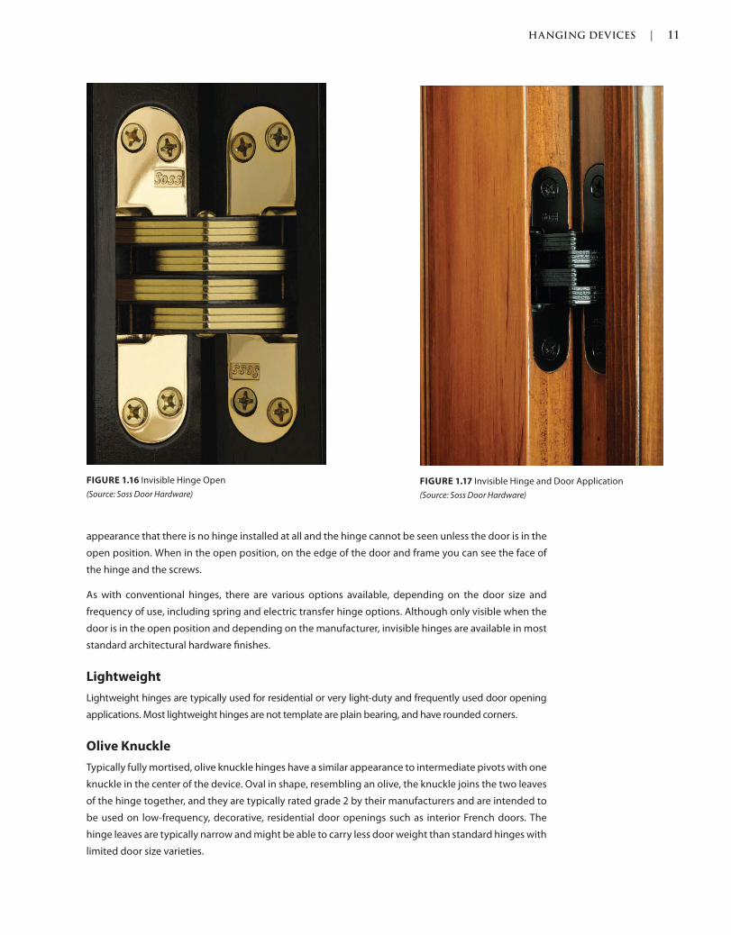
HANGING DEVICES | 11
c01.indd Page 11 03/02/2015 09:18:52:PM
appearance that there is no hinge installed at all and the hinge cannot be seen unless the door is in the
open position. When in the open position, on the edge of the door and frame you can see the face of
the hinge and the screws.
As with conventional hinges, there are various options available, depending on the door size and
frequency of use, including spring and electric transfer hinge options. Although only visible when the
door is in the open position and depending on the manufacturer, invisible hinges are available in most
standard architectural hardware finishes.
Lightweight
Lightweight hinges are typically used for residential or very light-duty and frequently used door opening
applications. Most lightweight hinges are not template are plain bearing, and have rounded corners.
Olive Knuckle
Typically fully mortised, olive knuckle hinges have a similar appearance to intermediate pivots with one
knuckle in the center of the device. Oval in shape, resembling an olive, the knuckle joins the two leaves
of the hinge together, and they are typically rated grade 2 by their manufacturers and are intended to
be used on low-frequency, decorative, residential door openings such as interior French doors. The
hinge leaves are typically narrow and might be able to carry less door weight than standard hinges with
limited door size varieties.
FIGURE 1.16 Invisible Hinge Open
(Source: Soss Door Hardware)
FIGURE 1.17 Invisible Hinge and Door Application
(Source: Soss Door Hardware)
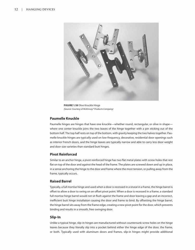
12 | HANGING DEVICES
c01.indd Page 12 03/02/2015 09:18:52:PM
FIGURE 1.18 Olive Knuckle Hinge
(Source: Courtesy of McKinney® Products Company)
Paumelle Knuckle
Paumelle hinges are hinges that have one knuckle—whether round, rectangular, or olive in shape—
where one center knuckle joins the two leaves of the hinge together with a pin sticking out of the
bottom half. The top half rests on top of the bottom, with gravity keeping the two halves together. Pau-
melle knuckle hinges are typically used on low-frequency, decorative, residential door openings such
as interior French doors, and the hinge leaves are typically narrow and able to carry less door weight
and door size varieties than standard butt hinges.
Pivot Reinforced
Similar to an anchor hinge, a pivot reinforced hinge has two flat metal plates with screw holes that rest
flat on top of the door and against the head of the frame. The plates are screwed down and up in place,
in a sense anchoring the hinge to the door and frame where the most tension, or pulling away from the
frame, typically occurs.
Raised Barrel
Typically, a full mortise hinge and used when a door is recessed in a reveal in a frame, the hinge barrel is
offset to allow a door to swing on an offset pivot point. When a door is recessed in a frame, a standard
full mortise hinge barrel would not sit flush against the frame and door leaving a gap and an incorrect,
inefficient butt hinge installation causing the door and frame to bind. By offsetting the hinge barrel,
the hinge barrel sits away from the frame edge, creating a new pivot point for the door, which prevents
binding and results in a smooth, free-swinging door.
Slip-In
Unlike a typical hinge, slip-in hinges are manufactured without countersunk screw holes on the hinge
leaves because they literally slip into a pocket behind either the hinge edge of the door, the frame,
or both. Typically used with aluminum doors and frames, slip-in hinges might provide additional
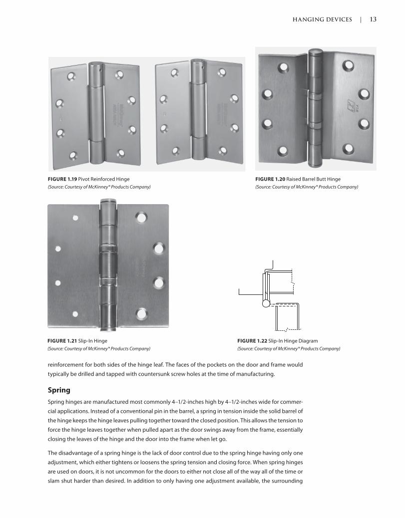
HANGING DEVICES | 13
c01.indd Page 13 03/02/2015 09:18:52:PM
reinforcement for both sides of the hinge leaf. The faces of the pockets on the door and frame would
typically be drilled and tapped with countersunk screw holes at the time of manufacturing.
Spring
Spring hinges are manufactured most commonly 4–1/2-inches high by 4–1/2-inches wide for commer-
cial applications. Instead of a conventional pin in the barrel, a spring in tension inside the solid barrel of
the hinge keeps the hinge leaves pulling together toward the closed position. This allows the tension to
force the hinge leaves together when pulled apart as the door swings away from the frame, essentially
closing the leaves of the hinge and the door into the frame when let go.
The disadvantage of a spring hinge is the lack of door control due to the spring hinge having only one
adjustment, which either tightens or loosens the spring tension and closing force. When spring hinges
are used on doors, it is not uncommon for the doors to either not close all of the way all of the time or
slam shut harder than desired. In addition to only having one adjustment available, the surrounding
FIGURE 1.19 Pivot Reinforced Hinge
(Source: Courtesy of McKinney® Products Company)
FIGURE 1.20 Raised Barrel Butt Hinge
(Source: Courtesy of McKinney® Products Company)
FIGURE 1.21 Slip-In Hinge
(Source: Courtesy of McKinney® Products Company)
FIGURE 1.22 Slip-In Hinge Diagram
(Source: Courtesy of McKinney® Products Company)
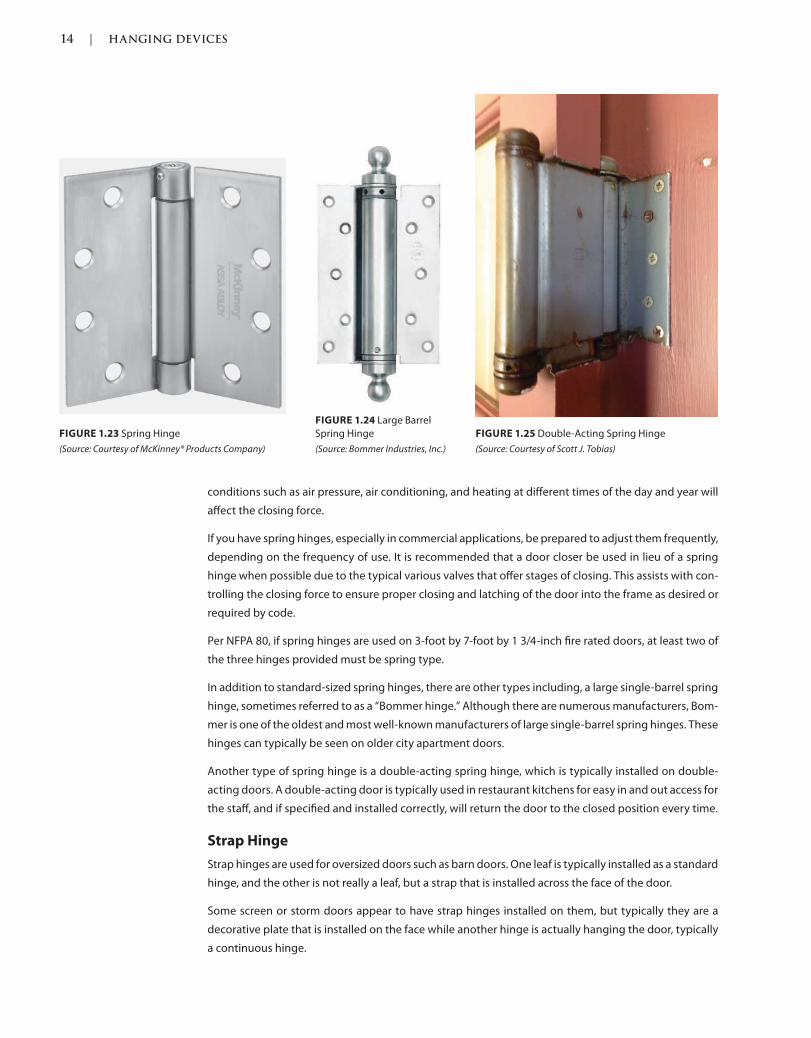
14 | HANGING DEVICES
c01.indd Page 14 03/02/2015 09:18:52:PM
conditions such as air pressure, air conditioning, and heating at different times of the day and year will
affect the closing force.
If you have spring hinges, especially in commercial applications, be prepared to adjust them frequently,
depending on the frequency of use. It is recommended that a door closer be used in lieu of a spring
hinge when possible due to the typical various valves that offer stages of closing. This assists with con-
trolling the closing force to ensure proper closing and latching of the door into the frame as desired or
required by code.
Per NFPA 80, if spring hinges are used on 3-foot by 7-foot by 1 3/4-inch fire rated doors, at least two of
the three hinges provided must be spring type.
In addition to standard-sized spring hinges, there are other types including, a large single-barrel spring
hinge, sometimes referred to as a “Bommer hinge.” Although there are numerous manufacturers, Bom-
mer is one of the oldest and most well-known manufacturers of large single-barrel spring hinges. These
hinges can typically be seen on older city apartment doors.
Another type of spring hinge is a double-acting spring hinge, which is typically installed on double-
acting doors. A double-acting door is typically used in restaurant kitchens for easy in and out access for
the staff, and if specified and installed correctly, will return the door to the closed position every time.
Strap Hinge
Strap hinges are used for oversized doors such as barn doors. One leaf is typically installed as a standard
hinge, and the other is not really a leaf, but a strap that is installed across the face of the door.
Some screen or storm doors appear to have strap hinges installed on them, but typically they are a
decorative plate that is installed on the face while another hinge is actually hanging the door, typically
a continuous hinge.
FIGURE 1.23 Spring Hinge
(Source: Courtesy of McKinney® Products Company)
FIGURE 1.24 Large Barrel
Spring Hinge
(Source: Bommer Industries, Inc.)
FIGURE 1.25 Double-Acting Spring Hinge
(Source: Courtesy of Scott J. Tobias)
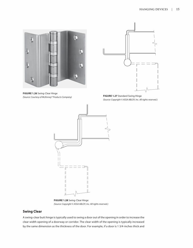
HANGING DEVICES | 15
c01.indd Page 15 03/02/2015 09:18:52:PM
Swing Clear
A swing-clear butt hinge is typically used to swing a door out of the opening in order to increase the
clear width opening of a doorway or corridor. The clear width of the opening is typically increased
by the same dimension as the thickness of the door. For example, if a door is 1 3/4-inches thick and
FIGURE 1.26 Swing-Clear Hinge
(Source: Courtesy of McKinney® Products Company) FIGURE 1.27 Standard Swing Hinge
(Source: Copyright © ASSA ABLOY, Inc. All rights reserved.)
FIGURE 1.28 Swing-Clear Hinge
(Source: Copyright © ASSA ABLOY, Inc. All rights reserved.)
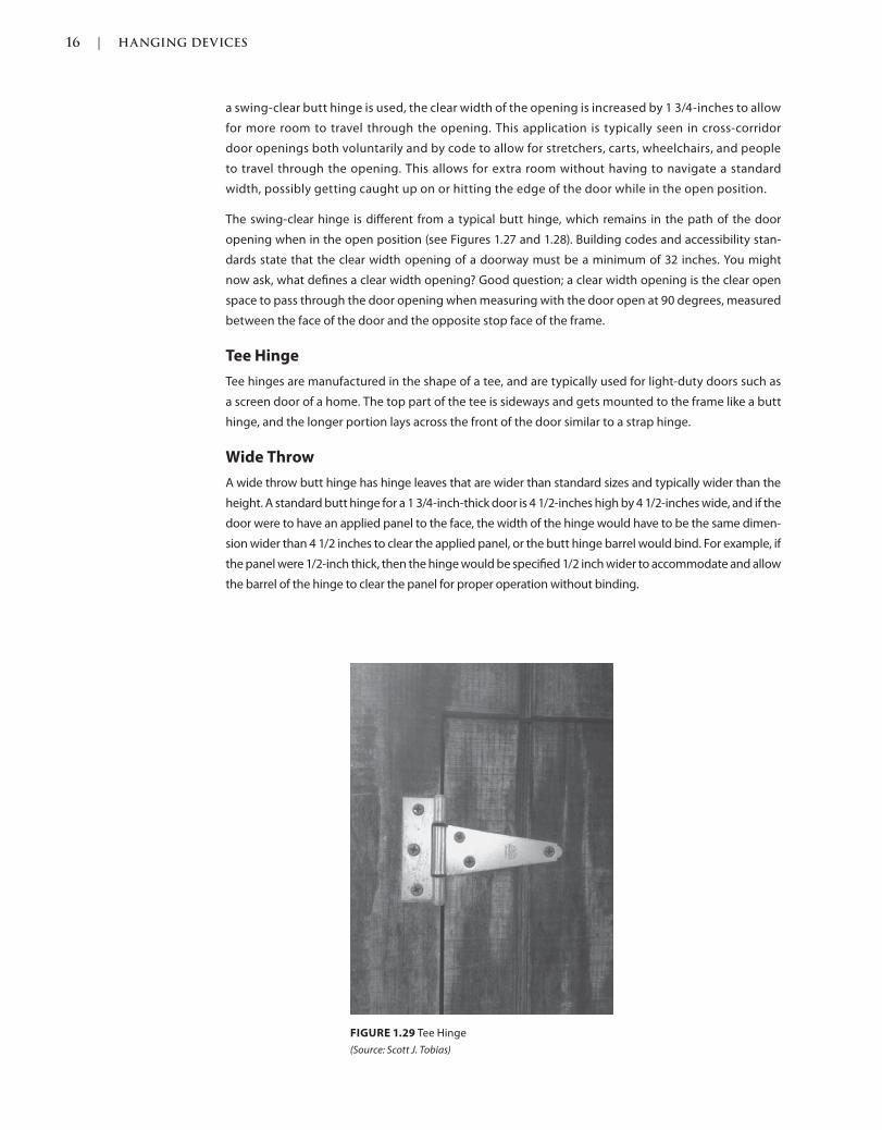
16 | HANGING DEVICES
c01.indd Page 16 03/02/2015 09:18:52:PM
a swing-clear butt hinge is used, the clear width of the opening is increased by 1 3/4-inches to allow
for more room to travel through the opening. This application is typically seen in cross-corridor
door openings both voluntarily and by code to allow for stretchers, carts, wheelchairs, and people
to travel through the opening. This allows for extra room without having to navigate a standard
width, possibly getting caught up on or hitting the edge of the door while in the open position.
The swing-clear hinge is different from a typical butt hinge, which remains in the path of the door
opening when in the open position (see Figures 1.27 and 1.28). Building codes and accessibility stan-
dards state that the clear width opening of a doorway must be a minimum of 32 inches. You might
now ask, what defines a clear width opening? Good question; a clear width opening is the clear open
space to pass through the door opening when measuring with the door open at 90 degrees, measured
between the face of the door and the opposite stop face of the frame.
Tee Hinge
Tee hinges are manufactured in the shape of a tee, and are typically used for light-duty doors such as
a screen door of a home. The top part of the tee is sideways and gets mounted to the frame like a butt
hinge, and the longer portion lays across the front of the door similar to a strap hinge.
Wide Throw
A wide throw butt hinge has hinge leaves that are wider than standard sizes and typically wider than the
height. A standard butt hinge for a 1 3/4-inch-thick door is 4 1/2-inches high by 4 1/2-inches wide, and if the
door were to have an applied panel to the face, the width of the hinge would have to be the same dimen-
sion wider than 4 1/2 inches to clear the applied panel, or the butt hinge barrel would bind. For example, if
the panel were 1/2-inch thick, then the hinge would be specified 1/2 inch wider to accommodate and allow
the barrel of the hinge to clear the panel for proper operation without binding.
FIGURE 1.29 Tee Hinge
(Source: Scott J. Tobias)
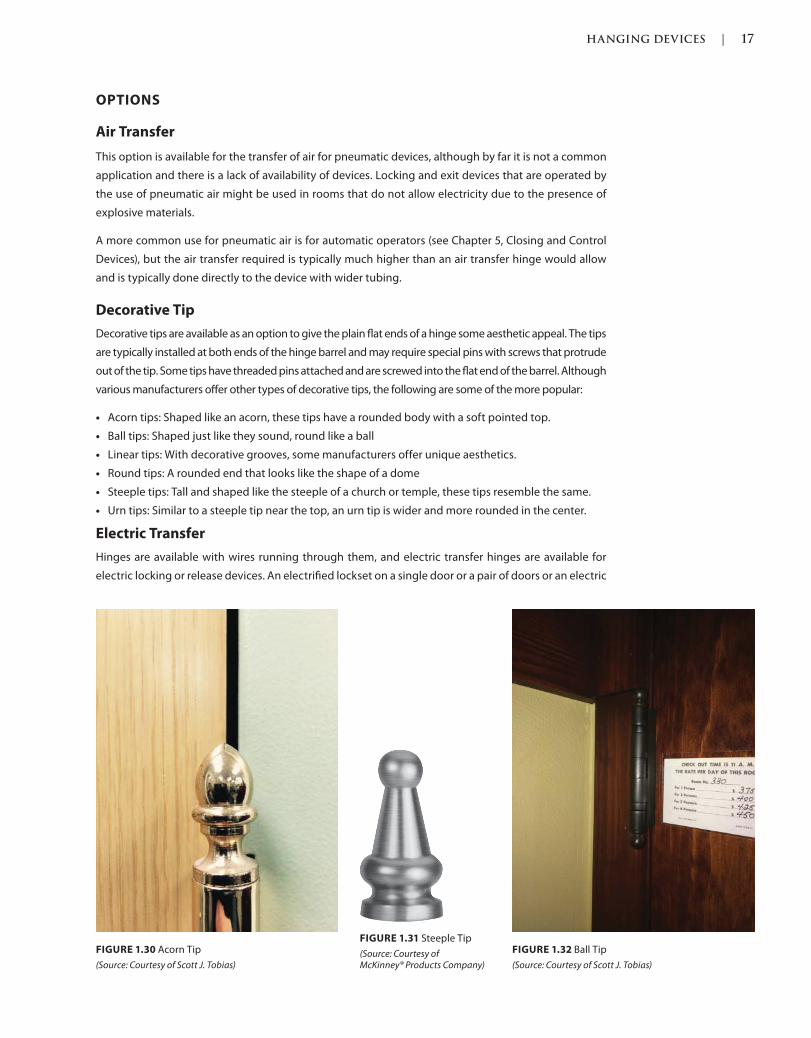
HANGING DEVICES | 17
c01.indd Page 17 03/02/2015 09:18:52:PM
OPTIONS
Air Transfer
This option is available for the transfer of air for pneumatic devices, although by far it is not a common
application and there is a lack of availability of devices. Locking and exit devices that are operated by
the use of pneumatic air might be used in rooms that do not allow electricity due to the presence of
explosive materials.
A more common use for pneumatic air is for automatic operators (see Chapter 5, Closing and Control
Devices), but the air transfer required is typically much higher than an air transfer hinge would allow
and is typically done directly to the device with wider tubing.
Decorative Tip
Decorative tips are available as an option to give the plain flat ends of a hinge some aesthetic appeal. The tips
are typically installed at both ends of the hinge barrel and may require special pins with screws that protrude
out of the tip. Some tips have threaded pins attached and are screwed into the flat end of the barrel. Although
various manufacturers offer other types of decorative tips, the following are some of the more popular:
Acorn tips: Shaped like an acorn, these tips have a rounded body with a soft pointed top.
Ball tips: Shaped just like they sound, round like a ball
Linear tips: With decorative grooves, some manufacturers offer unique aesthetics.
Round tips: A rounded end that looks like the shape of a dome
Steeple tips: Tall and shaped like the steeple of a church or temple, these tips resemble the same.
Urn tips: Similar to a steeple tip near the top, an urn tip is wider and more rounded in the center.
Electric Transfer
Hinges are available with wires running through them, and electric transfer hinges are available for
electric locking or release devices. An electrified lockset on a single door or a pair of doors or an electric
FIGURE 1.31 Steeple Tip
(Source: Courtesy of McKinney® Products Company)
FIGURE 1.30 Acorn Tip
(Source: Courtesy of Scott J. Tobias)
FIGURE 1.32 Ball Tip
(Source: Courtesy of Scott J. Tobias)
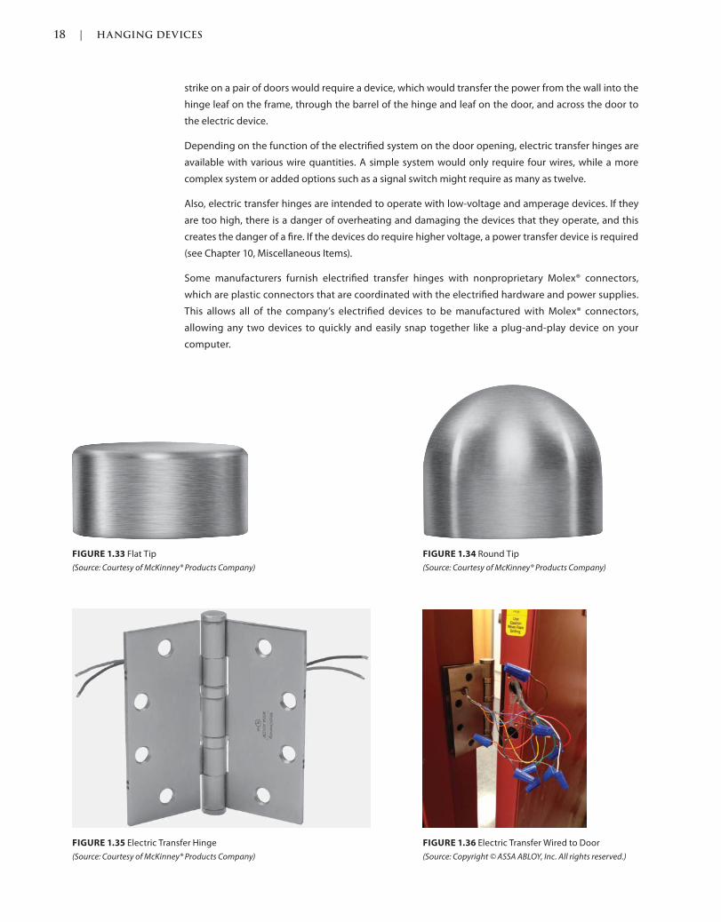
18 | HANGING DEVICES
c01.indd Page 18 03/02/2015 09:18:52:PM
FIGURE 1.34 Round Tip
(Source: Courtesy of McKinney® Products Company)
FIGURE 1.33 Flat Tip
(Source: Courtesy of McKinney® Products Company)
FIGURE 1.35 Electric Transfer Hinge
(Source: Courtesy of McKinney® Products Company)
FIGURE 1.36 Electric Transfer Wired to Door
(Source: Copyright © ASSA ABLOY, Inc. All rights reserved.)
strike on a pair of doors would require a device, which would transfer the power from the wall into the
hinge leaf on the frame, through the barrel of the hinge and leaf on the door, and across the door to
the electric device.
Depending on the function of the electrified system on the door opening, electric transfer hinges are
available with various wire quantities. A simple system would only require four wires, while a more
complex system or added options such as a signal switch might require as many as twelve.
Also, electric transfer hinges are intended to operate with low-voltage and amperage devices. If they
are too high, there is a danger of overheating and damaging the devices that they operate, and this
creates the danger of a fire. If the devices do require higher voltage, a power transfer device is required
(see Chapter 10, Miscellaneous Items).
Some manufacturers furnish electrified transfer hinges with nonproprietary Molex® connectors,
which are plastic connectors that are coordinated with the electrified hardware and power supplies.
This allows all of the company’s electrified devices to be manufactured with Molex® connectors,
allowing any two devices to quickly and easily snap together like a plug-and-play device on your
computer.
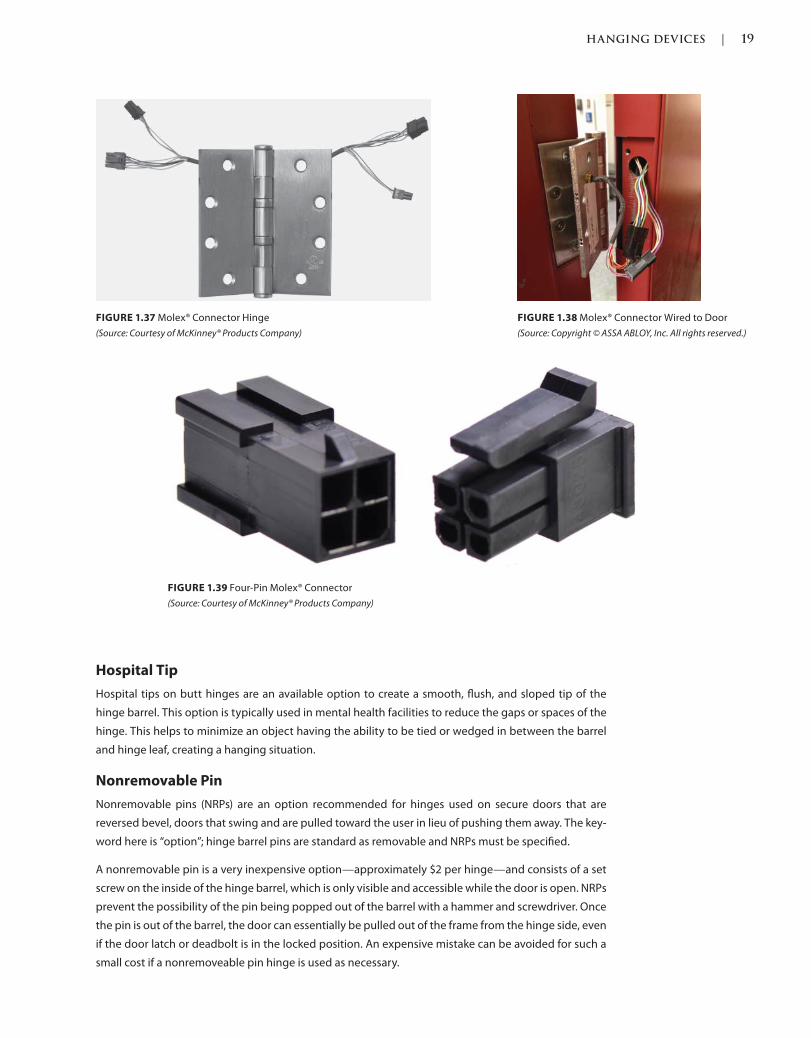
HANGING DEVICES | 19
c01.indd Page 19 03/02/2015 09:18:52:PM
Hospital Tip
Hospital tips on butt hinges are an available option to create a smooth, flush, and sloped tip of the
hinge barrel. This option is typically used in mental health facilities to reduce the gaps or spaces of the
hinge. This helps to minimize an object having the ability to be tied or wedged in between the barrel
and hinge leaf, creating a hanging situation.
Nonremovable Pin
Nonremovable pins (NRPs) are an option recommended for hinges used on secure doors that are
reversed bevel, doors that swing and are pulled toward the user in lieu of pushing them away. The key-
word here is “option”; hinge barrel pins are standard as removable and NRPs must be specified.
A nonremovable pin is a very inexpensive option—approximately $2 per hinge—and consists of a set
screw on the inside of the hinge barrel, which is only visible and accessible while the door is open. NRPs
prevent the possibility of the pin being popped out of the barrel with a hammer and screwdriver. Once
the pin is out of the barrel, the door can essentially be pulled out of the frame from the hinge side, even
if the door latch or deadbolt is in the locked position. An expensive mistake can be avoided for such a
small cost if a nonremoveable pin hinge is used as necessary.
FIGURE 1.37 Molex® Connector Hinge
(Source: Courtesy of McKinney® Products Company)
FIGURE 1.38 Molex® Connector Wired to Door
(Source: Copyright © ASSA ABLOY, Inc. All rights reserved.)
FIGURE 1.39 Four-Pin Molex® Connector
(Source: Courtesy of McKinney® Products Company)
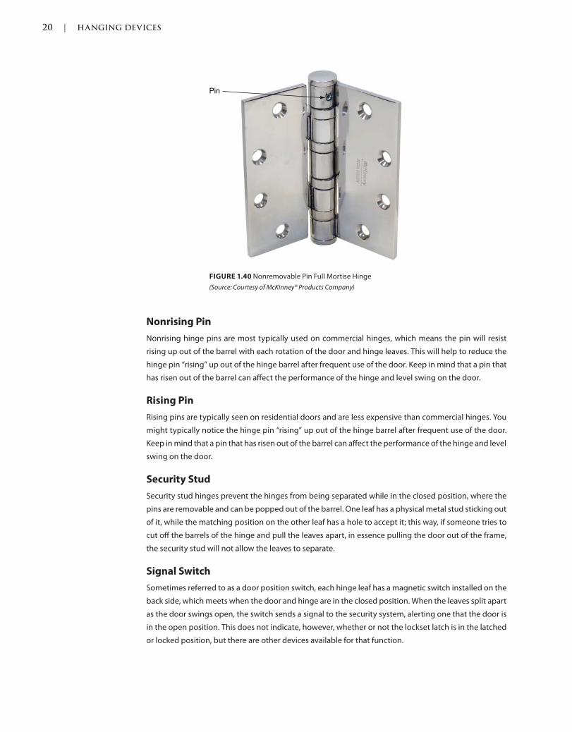
20 | HANGING DEVICES
c01.indd Page 20 03/02/2015 09:18:52:PM
Nonrising Pin
Nonrising hinge pins are most typically used on commercial hinges, which means the pin will resist
rising up out of the barrel with each rotation of the door and hinge leaves. This will help to reduce the
hinge pin “rising” up out of the hinge barrel after frequent use of the door. Keep in mind that a pin that
has risen out of the barrel can affect the performance of the hinge and level swing on the door.
Rising Pin
Rising pins are typically seen on residential doors and are less expensive than commercial hinges. You
might typically notice the hinge pin “rising” up out of the hinge barrel after frequent use of the door.
Keep in mind that a pin that has risen out of the barrel can affect the performance of the hinge and level
swing on the door.
Security Stud
Security stud hinges prevent the hinges from being separated while in the closed position, where the
pins are removable and can be popped out of the barrel. One leaf has a physical metal stud sticking out
of it, while the matching position on the other leaf has a hole to accept it; this way, if someone tries to
cut off the barrels of the hinge and pull the leaves apart, in essence pulling the door out of the frame,
the security stud will not allow the leaves to separate.
Signal Switch
Sometimes referred to as a door position switch, each hinge leaf has a magnetic switch installed on the
back side, which meets when the door and hinge are in the closed position. When the leaves split apart
as the door swings open, the switch sends a signal to the security system, alerting one that the door is
in the open position. This does not indicate, however, whether or not the lockset latch is in the latched
or locked position, but there are other devices available for that function.
FIGURE 1.40 Nonremovable Pin Full Mortise Hinge
(Source: Courtesy of McKinney® Products Company)
Pin
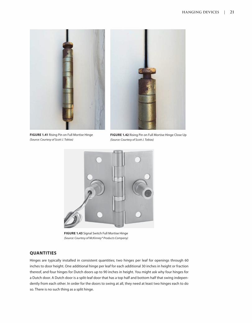
HANGING DEVICES | 21
c01.indd Page 21 03/02/2015 09:18:52:PM
QUANTITIES
Hinges are typically installed in consistent quantities; two hinges per leaf for openings through 60
inches to door height. One additional hinge per leaf for each additional 30 inches in height or fraction
thereof, and four hinges for Dutch doors up to 90 inches in height. You might ask why four hinges for
a Dutch door. A Dutch door is a split-leaf door that has a top half and bottom half that swing indepen-
dently from each other. In order for the doors to swing at all, they need at least two hinges each to do
so. There is no such thing as a split hinge.
FIGURE 1.41 Rising Pin on Full Mortise Hinge
(Source: Courtesy of Scott J. Tobias)
FIGURE 1.42 Rising Pin on Full Mortise Hinge Close Up
(Source: Courtesy of Scott J. Tobias)
FIGURE 1.43 Signal Switch Full Mortise Hinge
(Source: Courtesy of McKinney® Products Company)
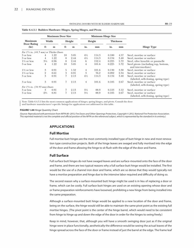
22 | HANGING DEVICES
c01.indd Page 22 03/02/2015 09:18:52:PM
APPLICATIONS
Full Mortise
Full mortise butt hinges are the most commonly installed type of butt hinge in new and most renova-
tion type construction projects. Both of the hinge leaves are swaged and fully mortised into the edge
of the door and frame allowing the hinge to sit flush with the edge of the door and frame.
Full Surface
Full surface butt hinges do not have swaged leaves and are surface-mounted onto the face of the door
and frame, and there are two typical reasons why a full surface butt hinge would be installed. The first
would be the use of a channel iron door and frame, which are so dense that they would typically not
have a mortise preparation and hinge due to the intensive labor required and difficulty of doing so.
The second reason why a surface-mounted butt hinge might be used is in lieu of replacing a door or
frame, which can be costly. Full surface butt hinges are used on an existing opening whose door and
or frame preparation reinforcements have loosened, prohibiting a new hinge from being installed into
the same preparation.
Although a surface-mounted butt hinge would be applied to a new location of the door and frame,
being on the surface, the hinge would still be able to maintain the same pivot point as the existing full
mortise hinges. (The pivot point is the center of the hinge barrel, which would need to be consistent
from hinge to hinge up and down the edge of the door in order for the hinges to swing freely.)
Keep in mind, however, that, although you will have a smooth swinging door just as if the original
hinge were in place functionally, aesthetically the difference would be seeing the actual leaves of the
hinge spread across the face of the door or frame instead of just the barrel at the edge. The frame leaf
FIGURE 1.44 Hinge Quantity Chart
(Source: Reproduced with permission from NFPA 80–2013, Fire Doors and Other Openings Protectives, Copyright © 2012, National Fire Protection Association. This reprinted material is not the complete and official position of the NFPA on the referenced subject, which is represented by the standard in its entirety.)
Table 6.4.3.1 Builders Hardware: Hinges, Spring Hinges, and Pivots
MaximumDoor Rating
(hr)
Maximum Door Size Minimum Hinge Size
Width Height Height Thickness
ft m ft m in. mm in. mm Hinge Type
For 13⁄4 in. (44.5 mm) or Thicker Doors3 or less 4 1.22 10 3.05 41⁄2 114.3 0.180 4.57 Steel, mortise or surface3 or less 4 1.22 8 2.44 41⁄2 114.3 0.134 3.40 Steel, mortise or surface11⁄2 or less 31⁄6 0.96 8 2.44 6 152.4 0.225 5.72 Steel, olive knuckle or paumelle3 or less 4 1.22 10 3.05 4 101.6 0.225 5.72 Steel pivots (including top, bottom,
and intermediate)11⁄2 or less 3 0.91 5 1.52 4 101.6 0.130 3.30 Steel, mortise or surface11⁄2 or less 2 0.61 3 0.91 3 76.2 0.092 2.34 Steel, mortise or surface3 or less 3 0.91 7 2.13 41⁄2 114.3 0.134 3.40 Steel, mortise or surface
(labeled, self-closing, spring type)3 or less 3 0.91 7 2.13 4 101.6 0.105 2.67 Steel, mortise or surface
(labeled, self-closing, spring type)For 13⁄8 in. (34.93 mm) Doors3 or less 3 0.91 7 2.13 31⁄2 88.9 0.123 3.12 Steel, mortise or surface3 or less 22⁄3 0.81 7 2.13 31⁄2 88.9 0.105 2.67 Steel, mortise or surface
(labeled, self-closing, spring type)
Note: Table 6.4.3.1 lists the most common applications of hinges, spring hinges, and pivots. Consult the doorand hardware manufacturer’s specific listings for applications not addressed in this table.
80–19SWINGING DOORS WITH BUILDERS HARDWARE
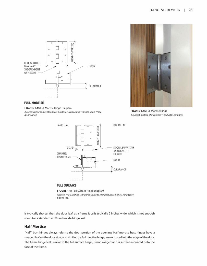
HANGING DEVICES | 23
c01.indd Page 23 03/02/2015 09:18:52:PM
is typically shorter than the door leaf, as a frame face is typically 2 inches wide, which is not enough
room for a standard 4 1/2-inch-wide hinge leaf.
Half Mortise
“Half” butt hinges always refer to the door portion of the opening. Half mortise butt hinges have a
swaged leaf on the door side, and similar to a full mortise hinge, are mortised into the edge of the door.
The frame hinge leaf, similar to the full surface hinge, is not swaged and is surface-mounted onto the
face of the frame.
FIGURE 1.45 Full Mortise Hinge Diagram
(Source: The Graphics Standards Guide to Architectural Finishes, John Wiley & Sons, Inc.)
FIGURE 1.46 Full Mortise Hinge
(Source: Courtesy of McKinney® Products Company)
FIGURE 1.47 Full Surface Hinge Diagram
(Source: The Graphics Standards Guide to Architectural Finishes, John Wiley & Sons, Inc.)
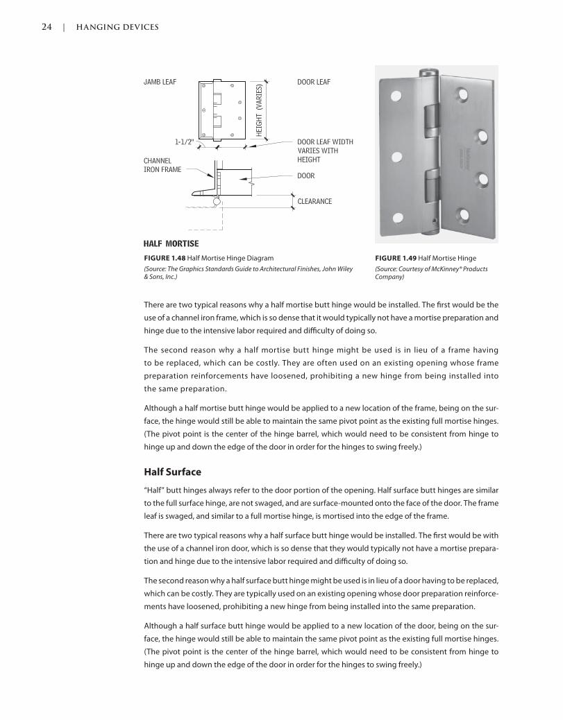
24 | HANGING DEVICES
c01.indd Page 24 03/02/2015 09:18:52:PM
There are two typical reasons why a half mortise butt hinge would be installed. The first would be the
use of a channel iron frame, which is so dense that it would typically not have a mortise preparation and
hinge due to the intensive labor required and difficulty of doing so.
The second reason why a half mortise butt hinge might be used is in lieu of a frame having
to be replaced, which can be costly. They are often used on an existing opening whose frame
preparation reinforcements have loosened, prohibiting a new hinge from being installed into
the same preparation.
Although a half mortise butt hinge would be applied to a new location of the frame, being on the sur-
face, the hinge would still be able to maintain the same pivot point as the existing full mortise hinges.
(The pivot point is the center of the hinge barrel, which would need to be consistent from hinge to
hinge up and down the edge of the door in order for the hinges to swing freely.)
Half Surface
“Half” butt hinges always refer to the door portion of the opening. Half surface butt hinges are similar
to the full surface hinge, are not swaged, and are surface-mounted onto the face of the door. The frame
leaf is swaged, and similar to a full mortise hinge, is mortised into the edge of the frame.
There are two typical reasons why a half surface butt hinge would be installed. The first would be with
the use of a channel iron door, which is so dense that they would typically not have a mortise prepara-
tion and hinge due to the intensive labor required and difficulty of doing so.
The second reason why a half surface butt hinge might be used is in lieu of a door having to be replaced,
which can be costly. They are typically used on an existing opening whose door preparation reinforce-
ments have loosened, prohibiting a new hinge from being installed into the same preparation.
Although a half surface butt hinge would be applied to a new location of the door, being on the sur-
face, the hinge would still be able to maintain the same pivot point as the existing full mortise hinges.
(The pivot point is the center of the hinge barrel, which would need to be consistent from hinge to
hinge up and down the edge of the door in order for the hinges to swing freely.)
FIGURE 1.48 Half Mortise Hinge Diagram
(Source: The Graphics Standards Guide to Architectural Finishes, John Wiley & Sons, Inc.)
FIGURE 1.49 Half Mortise Hinge
(Source: Courtesy of McKinney® Products Company)
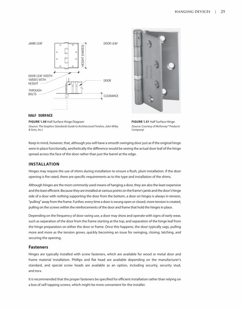
HANGING DEVICES | 25
c01.indd Page 25 03/02/2015 09:18:52:PM
Keep in mind, however, that, although you will have a smooth swinging door just as if the original hinge
were in place functionally, aesthetically the difference would be seeing the actual door leaf of the hinge
spread across the face of the door rather than just the barrel at the edge.
INSTALLATION
Hinges may require the use of shims during installation to ensure a flush, plum installation. If the door
opening is fire rated, there are specific requirements as to the type and installation of the shims.
Although hinges are the most commonly used means of hanging a door, they are also the least expensive
and the least efficient. Because they are installed at various points on the frame’s jamb and the door’s hinge
side of a door with nothing supporting the door from the bottom, a door on hinges is always in tension,
“pulling” away from the frame. Further, every time a door is swung open or closed, more tension is created,
pulling on the screws within the reinforcements of the door and frame that hold the hinges in place.
Depending on the frequency of door swing use, a door may show and operate with signs of early wear,
such as separation of the door from the frame starting at the top, and separation of the hinge leaf from
the hinge preparation on either the door or frame. Once this happens, the door typically sags, pulling
more and more as the tension grows, quickly becoming an issue for swinging, closing, latching, and
securing the opening.
Fasteners
Hinges are typically installed with screw fasteners, which are available for wood or metal door and
frame material installation. Phillips and flat head are available depending on the manufacturer’s
standard, and special screw heads are available as an option, including security, security stud,
and torx.
It is recommended that the proper fasteners be specified for efficient installation rather than relying on
a box of self-tapping screws, which might be more convenient for the installer.
FIGURE 1.50 Half Surface Hinge Diagram
(Source: The Graphics Standards Guide to Architectural Finishes, John Wiley & Sons, Inc.)
FIGURE 1.51 Half Surface Hinge
(Source: Courtesy of McKinney® Products Company)
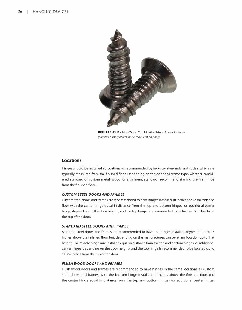
26 | HANGING DEVICES
c01.indd Page 26 03/02/2015 09:18:52:PM
Locations
Hinges should be installed at locations as recommended by industry standards and codes, which are
typically measured from the finished floor. Depending on the door and frame type, whether consid-
ered standard or custom metal, wood, or aluminum, standards recommend starting the first hinge
from the finished floor.
CUSTOM STEEL DOORS AND FRAMES
Custom steel doors and frames are recommended to have hinges installed 10 inches above the finished
floor with the center hinge equal in distance from the top and bottom hinges (or additional center
hinge, depending on the door height), and the top hinge is recommended to be located 5 inches from
the top of the door.
STANDARD STEEL DOORS AND FRAMES
Standard steel doors and frames are recommended to have the hinges installed anywhere up to 13
inches above the finished floor but, depending on the manufacturer, can be at any location up to that
height. The middle hinges are installed equal in distance from the top and bottom hinges (or additional
center hinge, depending on the door height), and the top hinge is recommended to be located up to
11 3/4 inches from the top of the door.
FLUSH WOOD DOORS AND FRAMES
Flush wood doors and frames are recommended to have hinges in the same locations as custom
steel doors and frames, with the bottom hinge installed 10 inches above the finished floor and
the center hinge equal in distance from the top and bottom hinges (or additional center hinge,
FIGURE 1.52 Machine-Wood Combination Hinge Screw Fastener
(Source: Courtesy of McKinney® Products Company)
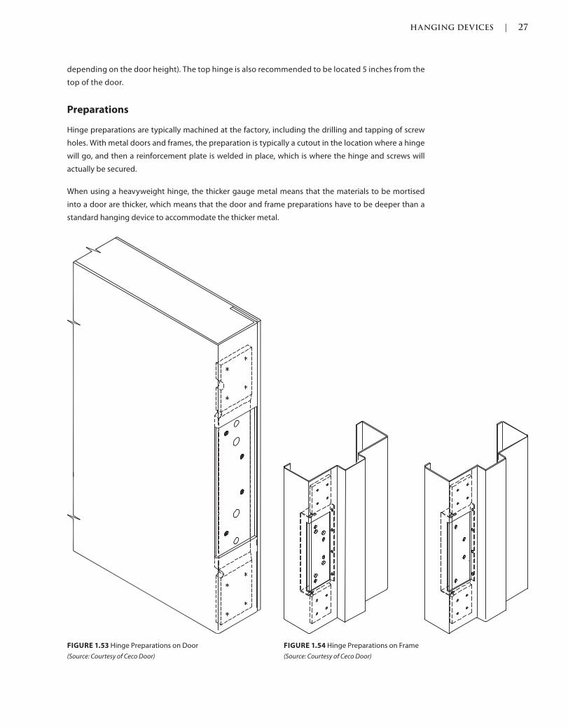
HANGING DEVICES | 27
c01.indd Page 27 03/02/2015 09:18:52:PM
depending on the door height). The top hinge is also recommended to be located 5 inches from the
top of the door.
Preparations
Hinge preparations are typically machined at the factory, including the drilling and tapping of screw
holes. With metal doors and frames, the preparation is typically a cutout in the location where a hinge
will go, and then a reinforcement plate is welded in place, which is where the hinge and screws will
actually be secured.
When using a heavyweight hinge, the thicker gauge metal means that the materials to be mortised
into a door are thicker, which means that the door and frame preparations have to be deeper than a
standard hanging device to accommodate the thicker metal.
FIGURE 1.53 Hinge Preparations on Door
(Source: Courtesy of Ceco Door)
FIGURE 1.54 Hinge Preparations on Frame
(Source: Courtesy of Ceco Door)
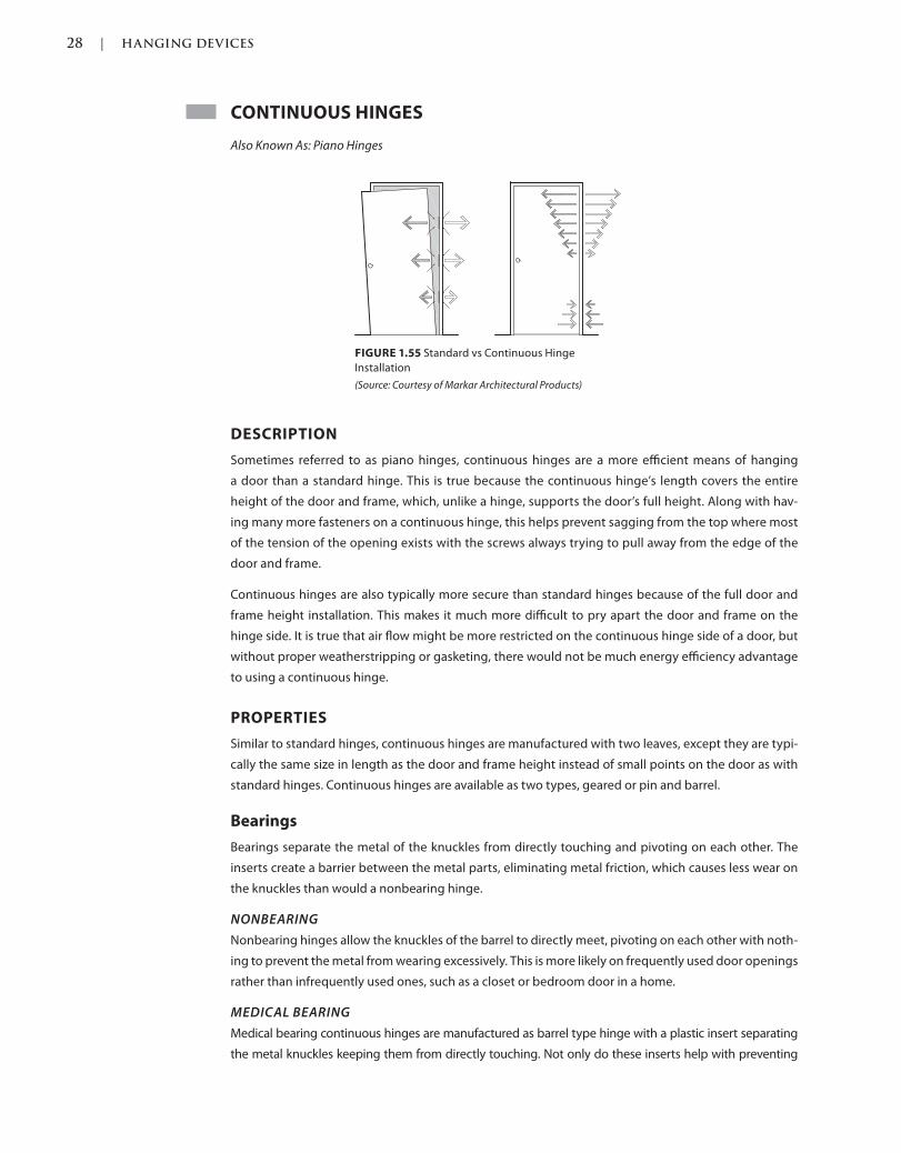
28 | HANGING DEVICES
c01.indd Page 28 03/02/2015 09:18:52:PM
CONTINUOUS HINGES
Also Known As: Piano Hinges
DESCRIPTION
Sometimes referred to as piano hinges, continuous hinges are a more efficient means of hanging
a door than a standard hinge. This is true because the continuous hinge’s length covers the entire
height of the door and frame, which, unlike a hinge, supports the door’s full height. Along with hav-
ing many more fasteners on a continuous hinge, this helps prevent sagging from the top where most
of the tension of the opening exists with the screws always trying to pull away from the edge of the
door and frame.
Continuous hinges are also typically more secure than standard hinges because of the full door and
frame height installation. This makes it much more difficult to pry apart the door and frame on the
hinge side. It is true that air flow might be more restricted on the continuous hinge side of a door, but
without proper weatherstripping or gasketing, there would not be much energy efficiency advantage
to using a continuous hinge.
PROPERTIES
Similar to standard hinges, continuous hinges are manufactured with two leaves, except they are typi-
cally the same size in length as the door and frame height instead of small points on the door as with
standard hinges. Continuous hinges are available as two types, geared or pin and barrel.
Bearings
Bearings separate the metal of the knuckles from directly touching and pivoting on each other. The
inserts create a barrier between the metal parts, eliminating metal friction, which causes less wear on
the knuckles than would a nonbearing hinge.
NONBEARING
Nonbearing hinges allow the knuckles of the barrel to directly meet, pivoting on each other with noth-
ing to prevent the metal from wearing excessively. This is more likely on frequently used door openings
rather than infrequently used ones, such as a closet or bedroom door in a home.
MEDICAL BEARING
Medical bearing continuous hinges are manufactured as barrel type hinge with a plastic insert separating
the metal knuckles keeping them from directly touching. Not only do these inserts help with preventing
FIGURE 1.55 Standard vs Continuous Hinge
Installation
(Source: Courtesy of Markar Architectural Products)
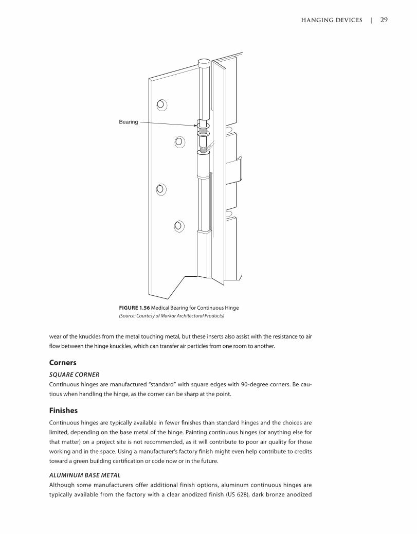
HANGING DEVICES | 29
c01.indd Page 29 03/02/2015 09:18:52:PM
wear of the knuckles from the metal touching metal, but these inserts also assist with the resistance to air
flow between the hinge knuckles, which can transfer air particles from one room to another.
Corners
SQUARE CORNER
Continuous hinges are manufactured “standard” with square edges with 90-degree corners. Be cau-
tious when handling the hinge, as the corner can be sharp at the point.
Finishes
Continuous hinges are typically available in fewer finishes than standard hinges and the choices are
limited, depending on the base metal of the hinge. Painting continuous hinges (or anything else for
that matter) on a project site is not recommended, as it will contribute to poor air quality for those
working and in the space. Using a manufacturer’s factory finish might even help contribute to credits
toward a green building certification or code now or in the future.
ALUMINUM BASE METAL
Although some manufacturers offer additional finish options, aluminum continuous hinges are
typically available from the factory with a clear anodized finish (US 628), dark bronze anodized
FIGURE 1.56 Medical Bearing for Continuous Hinge
(Source: Courtesy of Markar Architectural Products)
Bearing
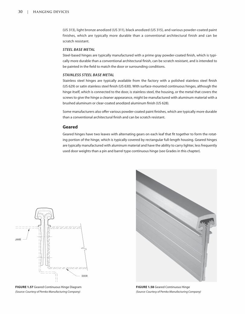
30 | HANGING DEVICES
c01.indd Page 30 03/02/2015 09:18:52:PM
(US 313), light bronze anodized (US 311), black anodized (US 315), and various powder-coated paint
finishes, which are typically more durable than a conventional architectural finish and can be
scratch resistant.
STEEL BASE METAL
Steel-based hinges are typically manufactured with a prime gray powder-coated finish, which is typi-
cally more durable than a conventional architectural finish, can be scratch resistant, and is intended to
be painted in the field to match the door or surrounding conditions.
STAINLESS STEEL BASE METAL
Stainless steel hinges are typically available from the factory with a polished stainless steel finish
(US 629) or satin stainless steel finish (US 630). With surface-mounted continuous hinges, although the
hinge itself, which is connected to the door, is stainless steel, the housing, or the metal that covers the
screws to give the hinge a cleaner appearance, might be manufactured with aluminum material with a
brushed aluminum or clear-coated anodized aluminum finish (US 628).
Some manufacturers also offer various powder-coated paint finishes, which are typically more durable
than a conventional architectural finish and can be scratch resistant.
Geared
Geared hinges have two leaves with alternating gears on each leaf that fit together to form the rotat-
ing portion of the hinge, which is typically covered by rectangular full-length housing. Geared hinges
are typically manufactured with aluminum material and have the ability to carry lighter, less frequently
used door weights than a pin and barrel type continuous hinge (see Grades in this chapter).
FIGURE 1.57 Geared Continuous Hinge Diagram
(Source: Courtesy of Pemko Manufacturing Company)
FIGURE 1.58 Geared Continuous Hinge
(Source: Courtesy of Pemko Manufacturing Company)
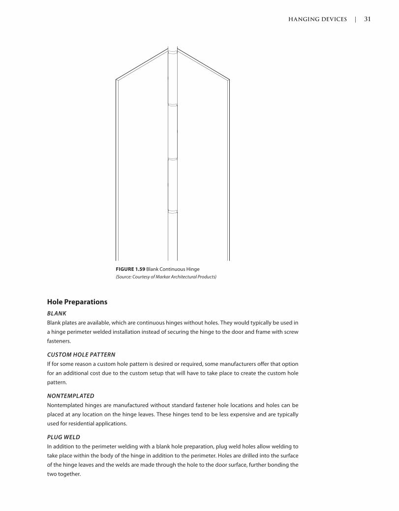
HANGING DEVICES | 31
c01.indd Page 31 03/02/2015 09:18:52:PM
Hole Preparations
BLANK
Blank plates are available, which are continuous hinges without holes. They would typically be used in
a hinge perimeter welded installation instead of securing the hinge to the door and frame with screw
fasteners.
CUSTOM HOLE PATTERN
If for some reason a custom hole pattern is desired or required, some manufacturers offer that option
for an additional cost due to the custom setup that will have to take place to create the custom hole
pattern.
NONTEMPLATED
Nontemplated hinges are manufactured without standard fastener hole locations and holes can be
placed at any location on the hinge leaves. These hinges tend to be less expensive and are typically
used for residential applications.
PLUG WELD
In addition to the perimeter welding with a blank hole preparation, plug weld holes allow welding to
take place within the body of the hinge in addition to the perimeter. Holes are drilled into the surface
of the hinge leaves and the welds are made through the hole to the door surface, further bonding the
two together.
FIGURE 1.59 Blank Continuous Hinge
(Source: Courtesy of Markar Architectural Products)
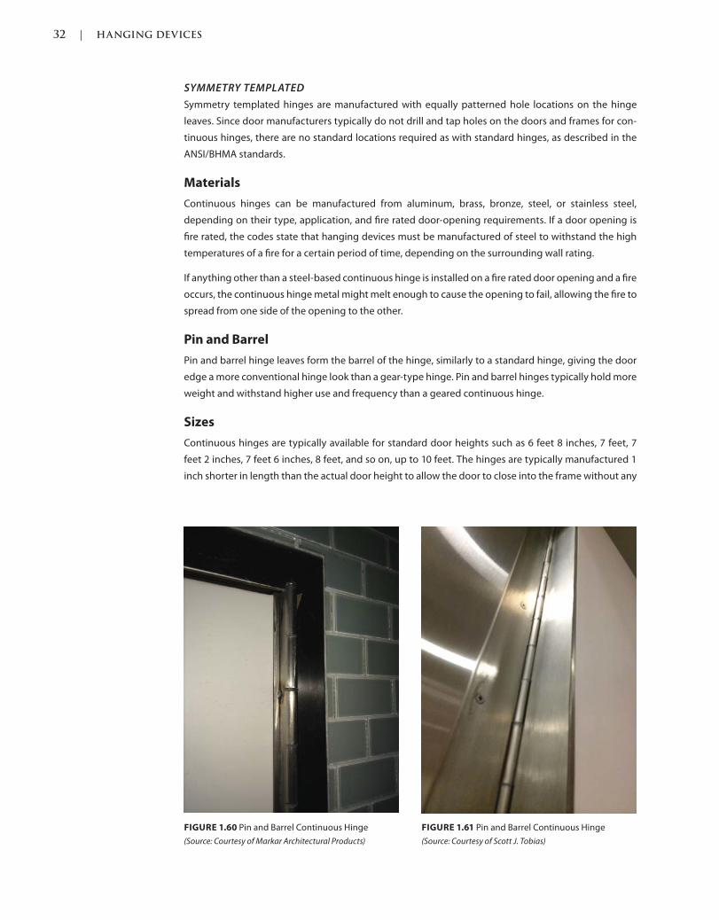
32 | HANGING DEVICES
c01.indd Page 32 03/02/2015 09:18:52:PM
SYMMETRY TEMPLATED
Symmetry templated hinges are manufactured with equally patterned hole locations on the hinge
leaves. Since door manufacturers typically do not drill and tap holes on the doors and frames for con-
tinuous hinges, there are no standard locations required as with standard hinges, as described in the
ANSI/BHMA standards.
Materials
Continuous hinges can be manufactured from aluminum, brass, bronze, steel, or stainless steel,
depending on their type, application, and fire rated door-opening requirements. If a door opening is
fire rated, the codes state that hanging devices must be manufactured of steel to withstand the high
temperatures of a fire for a certain period of time, depending on the surrounding wall rating.
If anything other than a steel-based continuous hinge is installed on a fire rated door opening and a fire
occurs, the continuous hinge metal might melt enough to cause the opening to fail, allowing the fire to
spread from one side of the opening to the other.
Pin and Barrel
Pin and barrel hinge leaves form the barrel of the hinge, similarly to a standard hinge, giving the door
edge a more conventional hinge look than a gear-type hinge. Pin and barrel hinges typically hold more
weight and withstand higher use and frequency than a geared continuous hinge.
Sizes
Continuous hinges are typically available for standard door heights such as 6 feet 8 inches, 7 feet, 7
feet 2 inches, 7 feet 6 inches, 8 feet, and so on, up to 10 feet. The hinges are typically manufactured 1
inch shorter in length than the actual door height to allow the door to close into the frame without any
FIGURE 1.60 Pin and Barrel Continuous Hinge
(Source: Courtesy of Markar Architectural Products)
FIGURE 1.61 Pin and Barrel Continuous Hinge
(Source: Courtesy of Scott J. Tobias)
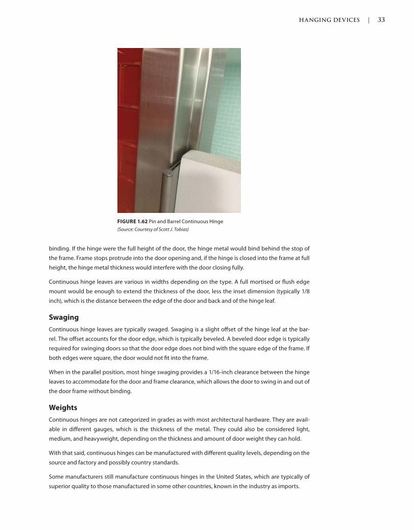
HANGING DEVICES | 33
c01.indd Page 33 03/02/2015 09:18:52:PM
binding. If the hinge were the full height of the door, the hinge metal would bind behind the stop of
the frame. Frame stops protrude into the door opening and, if the hinge is closed into the frame at full
height, the hinge metal thickness would interfere with the door closing fully.
Continuous hinge leaves are various in widths depending on the type. A full mortised or flush edge
mount would be enough to extend the thickness of the door, less the inset dimension (typically 1/8
inch), which is the distance between the edge of the door and back and of the hinge leaf.
Swaging
Continuous hinge leaves are typically swaged. Swaging is a slight offset of the hinge leaf at the bar-
rel. The offset accounts for the door edge, which is typically beveled. A beveled door edge is typically
required for swinging doors so that the door edge does not bind with the square edge of the frame. If
both edges were square, the door would not fit into the frame.
When in the parallel position, most hinge swaging provides a 1/16-inch clearance between the hinge
leaves to accommodate for the door and frame clearance, which allows the door to swing in and out of
the door frame without binding.
Weights
Continuous hinges are not categorized in grades as with most architectural hardware. They are avail-
able in different gauges, which is the thickness of the metal. They could also be considered light,
medium, and heavyweight, depending on the thickness and amount of door weight they can hold.
With that said, continuous hinges can be manufactured with different quality levels, depending on the
source and factory and possibly country standards.
Some manufacturers still manufacture continuous hinges in the United States, which are typically of
superior quality to those manufactured in some other countries, known in the industry as imports.
FIGURE 1.62 Pin and Barrel Continuous Hinge
(Source: Courtesy of Scott J. Tobias)
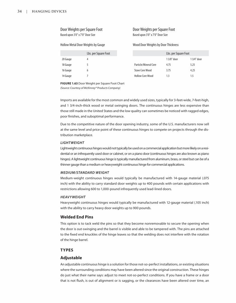
34 | HANGING DEVICES
c01.indd Page 34 03/02/2015 09:18:52:PM
Imports are available for the most common and widely used sizes, typically for 3-feet-wide, 7-feet-high,
and 1 3/4-inch-thick wood or metal swinging doors. The continuous hinges are less expensive than
those still made in the United States and the low quality can sometimes be noticed with ragged edges,
poor finishes, and suboptimal performance.
Due to the competitive nature of the door opening industry, some of the U.S. manufacturers now sell
at the same level and price point of these continuous hinges to compete on projects through the dis-
tribution marketplace.
LIGHTWEIGHT
Lightweight continuous hinges would not typically be used on a commercial application but more likely on a resi-
dential or an infrequently used door or cabinet, or on a piano door (continuous hinges are also known as piano
hinges). A lightweight continuous hinge is typically manufactured from aluminum, brass, or steel but can be of a
thinner gauge than a medium or heavyweight continuous hinge for commercial applications.
MEDIUM/STANDARD WEIGHT
Medium-weight continuous hinges would typically be manufactured with 14-gauge material (.075
inch) with the ability to carry standard door weights up to 400 pounds with certain applications with
restrictions allowing 600 to 1,000-pound infrequently used lead-lined doors.
HEAVYWEIGHT
Heavyweight continuous hinges would typically be manufactured with 12-gauge material (.105 inch)
with the ability to carry heavy door weights up to 900 pounds.
Welded End Pins
This option is to tack weld the pins so that they become nonremovable to secure the opening when
the door is out-swinging and the barrel is visible and able to be tampered with. The pins are attached
to the fixed end knuckles of the hinge leaves so that the welding does not interfere with the rotation
of the hinge barrel.
TYPES
Adjustable
An adjustable continuous hinge is a solution for those not-so-perfect installations, or existing situations
where the surrounding conditions may have been altered since the original construction. These hinges
do just what their name says: adjust to meet not-so-perfect conditions. If you have a frame or a door
that is not flush, is out of alignment or is sagging, or the clearances have been altered over time, an
FIGURE 1.63 Door Weight per Square Foot Chart
(Source: Courtesy of McKinney® Products Company)
Door Weights per Square FootBased upon 3'0" x 7'0" Door Size
Hollow Metal Door Weights by Gauge
Lbs. per Square Foot
20 Gauge 4
18 Gauge 5
16 Gauge 6
14 Gauge 7
Door Weights per Square FootBased upon 3'0" x 7'0" Door Size
Wood Door Weights by Door Thickness
Lbs. per Square Foot
1 3/8" door 1 3/4" door
Particle/Mineral Core 4.75 5.25
Stave Core Wood 3.75 4.25
Hollow Core Wood 1.3 1.5
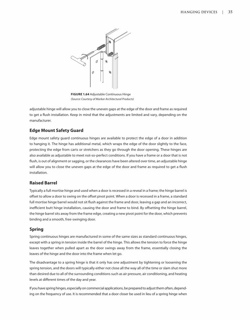
HANGING DEVICES | 35
c01.indd Page 35 03/02/2015 09:18:52:PM
adjustable hinge will allow you to close the uneven gaps at the edge of the door and frame as required
to get a flush installation. Keep in mind that the adjustments are limited and vary, depending on the
manufacturer.
Edge Mount Safety Guard
Edge mount safety guard continuous hinges are available to protect the edge of a door in addition
to hanging it. The hinge has additional metal, which wraps the edge of the door slightly to the face,
protecting the edge from carts or stretchers as they go through the door opening. These hinges are
also available as adjustable to meet not-so-perfect conditions. If you have a frame or a door that is not
flush, is out of alignment or sagging, or the clearances have been altered over time, an adjustable hinge
will allow you to close the uneven gaps at the edge of the door and frame as required to get a flush
installation.
Raised Barrel
Typically a full mortise hinge and used when a door is recessed in a reveal in a frame; the hinge barrel is
offset to allow a door to swing on the offset pivot point. When a door is recessed in a frame, a standard
full mortise hinge barrel would not sit flush against the frame and door, leaving a gap and an incorrect,
inefficient butt hinge installation, causing the door and frame to bind. By offsetting the hinge barrel,
the hinge barrel sits away from the frame edge, creating a new pivot point for the door, which prevents
binding and a smooth, free-swinging door.
Spring
Spring continuous hinges are manufactured in some of the same sizes as standard continuous hinges,
except with a spring in tension inside the barrel of the hinge. This allows the tension to force the hinge
leaves together when pulled apart as the door swings away from the frame, essentially closing the
leaves of the hinge and the door into the frame when let go.
The disadvantage to a spring hinge is that it only has one adjustment by tightening or loosening the
spring tension, and the doors will typically either not close all the way all of the time or slam shut more
than desired due to all of the surrounding conditions such as air pressure, air conditioning, and heating
levels at different times of the day and year.
If you have spring hinges, especially on commercial applications, be prepared to adjust them often, depend-
ing on the frequency of use. It is recommended that a door closer be used in lieu of a spring hinge when
FIGURE 1.64 Adjustable Continuous Hinge
(Source: Courtesy of Markar Architectural Products)
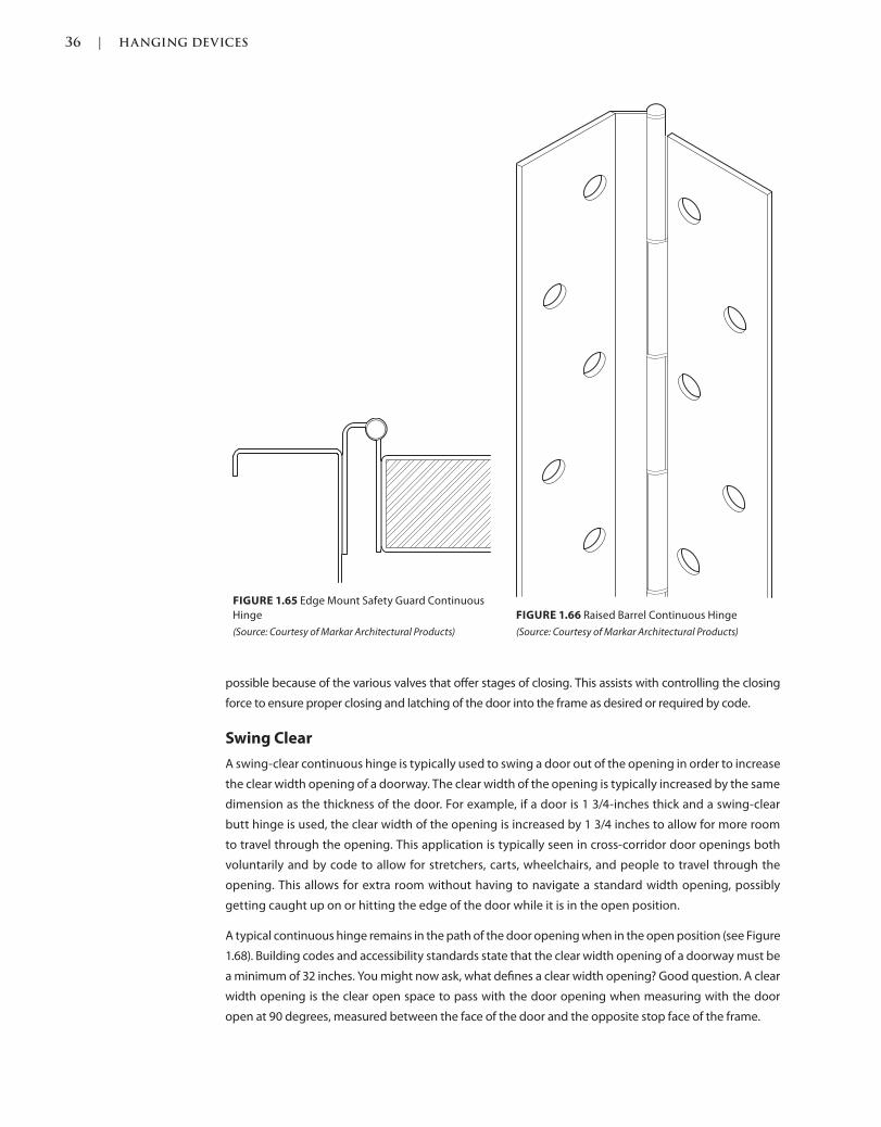
36 | HANGING DEVICES
c01.indd Page 36 03/02/2015 09:18:52:PM
possible because of the various valves that offer stages of closing. This assists with controlling the closing
force to ensure proper closing and latching of the door into the frame as desired or required by code.
Swing Clear
A swing-clear continuous hinge is typically used to swing a door out of the opening in order to increase
the clear width opening of a doorway. The clear width of the opening is typically increased by the same
dimension as the thickness of the door. For example, if a door is 1 3/4-inches thick and a swing-clear
butt hinge is used, the clear width of the opening is increased by 1 3/4 inches to allow for more room
to travel through the opening. This application is typically seen in cross-corridor door openings both
voluntarily and by code to allow for stretchers, carts, wheelchairs, and people to travel through the
opening. This allows for extra room without having to navigate a standard width opening, possibly
getting caught up on or hitting the edge of the door while it is in the open position.
A typical continuous hinge remains in the path of the door opening when in the open position (see Figure
1.68). Building codes and accessibility standards state that the clear width opening of a doorway must be
a minimum of 32 inches. You might now ask, what defines a clear width opening? Good question. A clear
width opening is the clear open space to pass with the door opening when measuring with the door
open at 90 degrees, measured between the face of the door and the opposite stop face of the frame.
FIGURE 1.65 Edge Mount Safety Guard Continuous
Hinge
(Source: Courtesy of Markar Architectural Products)
FIGURE 1.66 Raised Barrel Continuous Hinge
(Source: Courtesy of Markar Architectural Products)

HANGING DEVICES | 37
c01.indd Page 37 03/02/2015 09:18:52:PM
To explain further, let’s go through an example opening using a 36-inch-wide, 1 3/4-inches-thick hol-
low metal door and frame swinging on a standard mortise continuous hinge. Using the code to guide
us as to where to measure, we come to the clear width dimension by deducting the door thickness,
which is 1 3/4 inches, plus the width of both stops of the frame, which is typically 5/8-inch thick each, for
a total of 3 inches. Deduct 3 inches from the original door width of 36 inches, and that leaves a 33-inch
clear-width opening, which complies with the codes and standards. In addition, there are also restric-
tions regarding projections of door hardware into the clear width, so that it does not interfere with the
clear-width requirement.
FIGURE 1.67 Swing-Clear Continuous Hinge
(Source: Courtesy of Markar Architectural Products)
FIGURE 1.68 Standard Continuous (A) vs Swing-Clear (B) Continuous Hinge
(Source: Copyright © ASSA ABLOY, Inc. All rights reserved.)
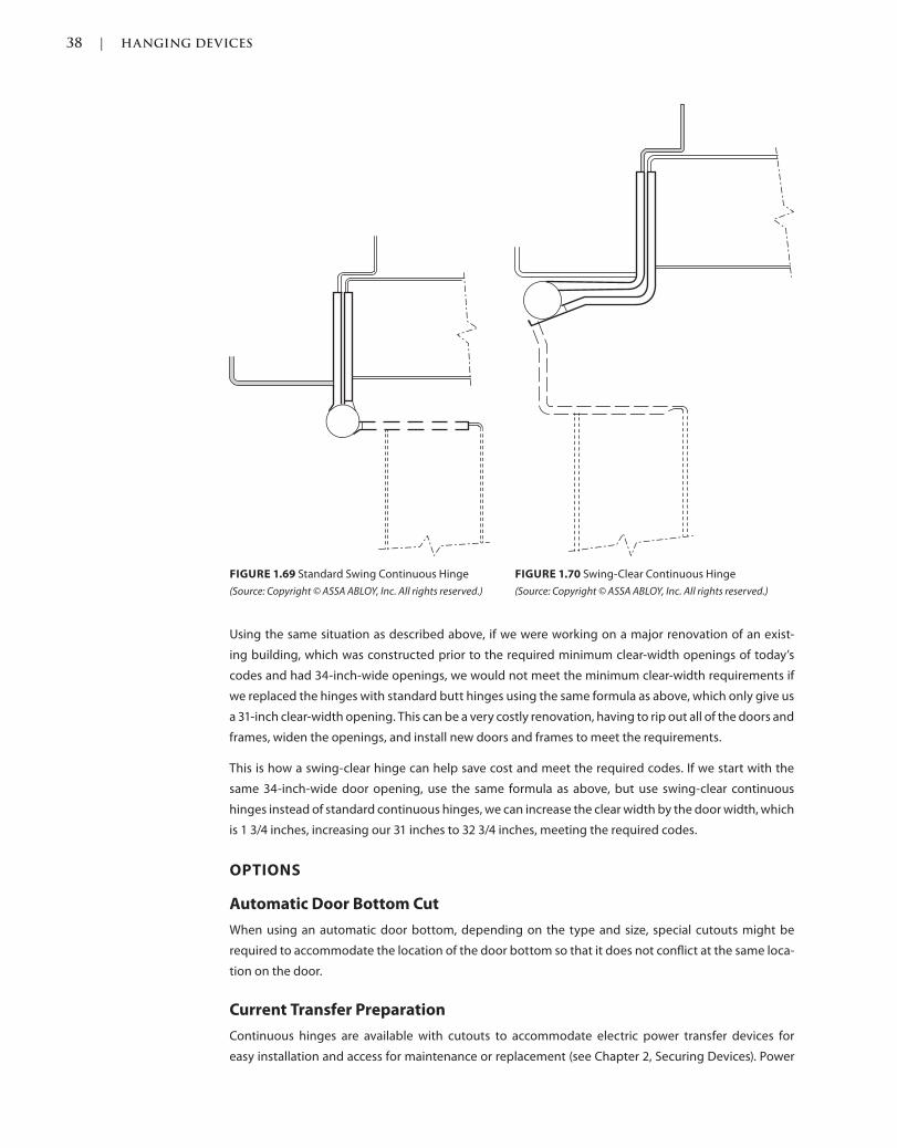
38 | HANGING DEVICES
c01.indd Page 38 03/02/2015 09:18:52:PM
FIGURE 1.69 Standard Swing Continuous Hinge
(Source: Copyright © ASSA ABLOY, Inc. All rights reserved.)
FIGURE 1.70 Swing-Clear Continuous Hinge
(Source: Copyright © ASSA ABLOY, Inc. All rights reserved.)
Using the same situation as described above, if we were working on a major renovation of an exist-
ing building, which was constructed prior to the required minimum clear-width openings of today’s
codes and had 34-inch-wide openings, we would not meet the minimum clear-width requirements if
we replaced the hinges with standard butt hinges using the same formula as above, which only give us
a 31-inch clear-width opening. This can be a very costly renovation, having to rip out all of the doors and
frames, widen the openings, and install new doors and frames to meet the requirements.
This is how a swing-clear hinge can help save cost and meet the required codes. If we start with the
same 34-inch-wide door opening, use the same formula as above, but use swing-clear continuous
hinges instead of standard continuous hinges, we can increase the clear width by the door width, which
is 1 3/4 inches, increasing our 31 inches to 32 3/4 inches, meeting the required codes.
OPTIONS
Automatic Door Bottom Cut
When using an automatic door bottom, depending on the type and size, special cutouts might be
required to accommodate the location of the door bottom so that it does not conflict at the same loca-
tion on the door.
Current Transfer Preparation
Continuous hinges are available with cutouts to accommodate electric power transfer devices for
easy installation and access for maintenance or replacement (see Chapter 2, Securing Devices). Power
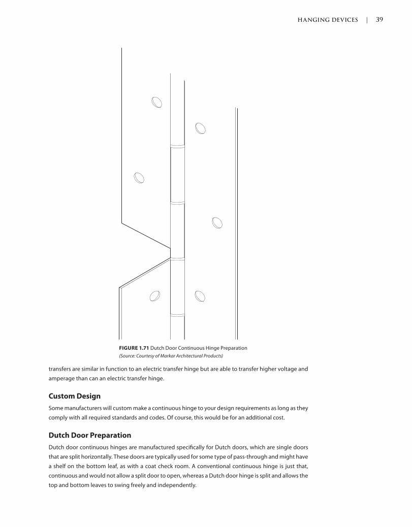
HANGING DEVICES | 39
c01.indd Page 39 03/02/2015 09:18:52:PM
transfers are similar in function to an electric transfer hinge but are able to transfer higher voltage and
amperage than can an electric transfer hinge.
Custom Design
Some manufacturers will custom make a continuous hinge to your design requirements as long as they
comply with all required standards and codes. Of course, this would be for an additional cost.
Dutch Door Preparation
Dutch door continuous hinges are manufactured specifically for Dutch doors, which are single doors
that are split horizontally. These doors are typically used for some type of pass-through and might have
a shelf on the bottom leaf, as with a coat check room. A conventional continuous hinge is just that,
continuous and would not allow a split door to open, whereas a Dutch door hinge is split and allows the
top and bottom leaves to swing freely and independently.
FIGURE 1.71 Dutch Door Continuous Hinge Preparation
(Source: Courtesy of Markar Architectural Products)
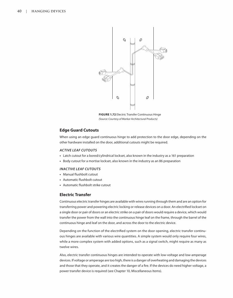
40 | HANGING DEVICES
c01.indd Page 40 03/02/2015 09:18:52:PM
Edge Guard Cutouts
When using an edge guard continuous hinge to add protection to the door edge, depending on the
other hardware installed on the door, additional cutouts might be required.
ACTIVE LEAF CUTOUTS
Latch cutout for a bored/cylindrical lockset, also known in the industry as a 161 preparation
Body cutout for a mortise lockset, also known in the industry as an 86 preparation
INACTIVE LEAF CUTOUTS
Manual flushbolt cutout
Automatic flushbolt cutout
Automatic flushbolt strike cutout
Electric Transfer
Continuous electric transfer hinges are available with wires running through them and are an option for
transferring power and powering electric locking or release devices on a door. An electrified lockset on
a single door or pair of doors or an electric strike on a pair of doors would require a device, which would
transfer the power from the wall into the continuous hinge leaf on the frame, through the barrel of the
continuous hinge and leaf on the door, and across the door to the electric device.
Depending on the function of the electrified system on the door opening, electric transfer continu-
ous hinges are available with various wire quantities. A simple system would only require four wires,
while a more complex system with added options, such as a signal switch, might require as many as
twelve wires.
Also, electric transfer continuous hinges are intended to operate with low-voltage and low-amperage
devices. If voltage or amperage are too high, there is a danger of overheating and damaging the devices
and those that they operate, and it creates the danger of a fire. If the devices do need higher voltage, a
power transfer device is required (see Chapter 10, Miscellaneous Items).
FIGURE 1.72 Electric Transfer Continuous Hinge
(Source: Courtesy of Markar Architectural Products)
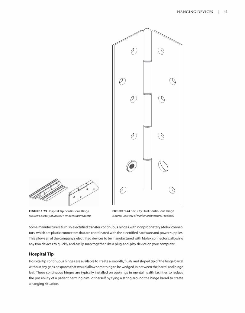
HANGING DEVICES | 41
c01.indd Page 41 03/02/2015 09:18:52:PM
Some manufacturers furnish electrified transfer continuous hinges with nonproprietary Molex connec-
tors, which are plastic connectors that are coordinated with the electrified hardware and power supplies.
This allows all of the company’s electrified devices to be manufactured with Molex connectors, allowing
any two devices to quickly and easily snap together like a plug-and-play device on your computer.
Hospital Tip
Hospital tip continuous hinges are available to create a smooth, flush, and sloped tip of the hinge barrel
without any gaps or spaces that would allow something to be wedged in between the barrel and hinge
leaf. These continuous hinges are typically installed on openings in mental health facilities to reduce
the possibility of a patient harming him- or herself by tying a string around the hinge barrel to create
a hanging situation.
FIGURE 1.74 Security Stud Continuous Hinge
(Source: Courtesy of Markar Architectural Products)
FIGURE 1.73 Hospital Tip Continuous Hinge
(Source: Courtesy of Markar Architectural Products)
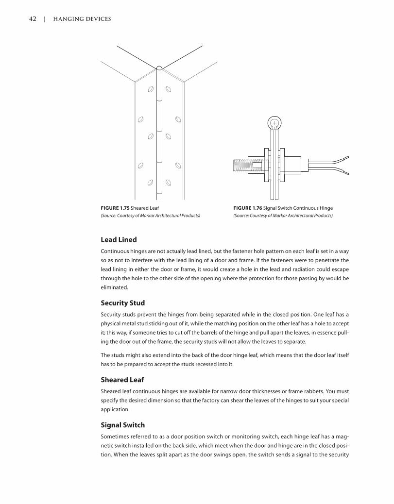
42 | HANGING DEVICES
c01.indd Page 42 03/02/2015 09:18:52:PM
Lead Lined
Continuous hinges are not actually lead lined, but the fastener hole pattern on each leaf is set in a way
so as not to interfere with the lead lining of a door and frame. If the fasteners were to penetrate the
lead lining in either the door or frame, it would create a hole in the lead and radiation could escape
through the hole to the other side of the opening where the protection for those passing by would be
eliminated.
Security Stud
Security studs prevent the hinges from being separated while in the closed position. One leaf has a
physical metal stud sticking out of it, while the matching position on the other leaf has a hole to accept
it; this way, if someone tries to cut off the barrels of the hinge and pull apart the leaves, in essence pull-
ing the door out of the frame, the security studs will not allow the leaves to separate.
The studs might also extend into the back of the door hinge leaf, which means that the door leaf itself
has to be prepared to accept the studs recessed into it.
Sheared Leaf
Sheared leaf continuous hinges are available for narrow door thicknesses or frame rabbets. You must
specify the desired dimension so that the factory can shear the leaves of the hinges to suit your special
application.
Signal Switch
Sometimes referred to as a door position switch or monitoring switch, each hinge leaf has a mag-
netic switch installed on the back side, which meet when the door and hinge are in the closed posi-
tion. When the leaves split apart as the door swings open, the switch sends a signal to the security
FIGURE 1.75 Sheared Leaf
(Source: Courtesy of Markar Architectural Products)
FIGURE 1.76 Signal Switch Continuous Hinge
(Source: Courtesy of Markar Architectural Products)
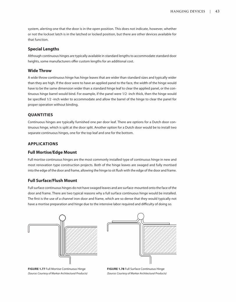
HANGING DEVICES | 43
c01.indd Page 43 03/02/2015 09:18:52:PM
system, alerting one that the door is in the open position. This does not indicate, however, whether
or not the lockset latch is in the latched or locked position, but there are other devices available for
that function.
Special Lengths
Although continuous hinges are typically available in standard lengths to accommodate standard door
heights, some manufacturers offer custom lengths for an additional cost.
Wide Throw
A wide throw continuous hinge has hinge leaves that are wider than standard sizes and typically wider
than they are high. If the door were to have an applied panel to the face, the width of the hinge would
have to be the same dimension wider than a standard hinge leaf to clear the applied panel, or the con-
tinuous hinge barrel would bind. For example, if the panel were 1/2 -inch thick, then the hinge would
be specified 1/2 -inch wider to accommodate and allow the barrel of the hinge to clear the panel for
proper operation without binding.
QUANTITIES
Continuous hinges are typically furnished one per door leaf. There are options for a Dutch door con-
tinuous hinge, which is split at the door split. Another option for a Dutch door would be to install two
separate continuous hinges, one for the top leaf and one for the bottom.
APPLICATIONS
Full Mortise/Edge Mount
Full mortise continuous hinges are the most commonly installed type of continuous hinge in new and
most renovation type construction projects. Both of the hinge leaves are swaged and fully mortised
into the edge of the door and frame, allowing the hinge to sit flush with the edge of the door and frame.
Full Surface/Flush Mount
Full surface continuous hinges do not have swaged leaves and are surface-mounted onto the face of the
door and frame. There are two typical reasons why a full surface continuous hinge would be installed.
The first is the use of a channel iron door and frame, which are so dense that they would typically not
have a mortise preparation and hinge due to the intensive labor required and difficulty of doing so.
FIGURE 1.77 Full Mortise Continuous Hinge
(Source: Courtesy of Markar Architectural Products)
FIGURE 1.78 Full Surface Continuous Hinge
(Source: Courtesy of Markar Architectural Products)
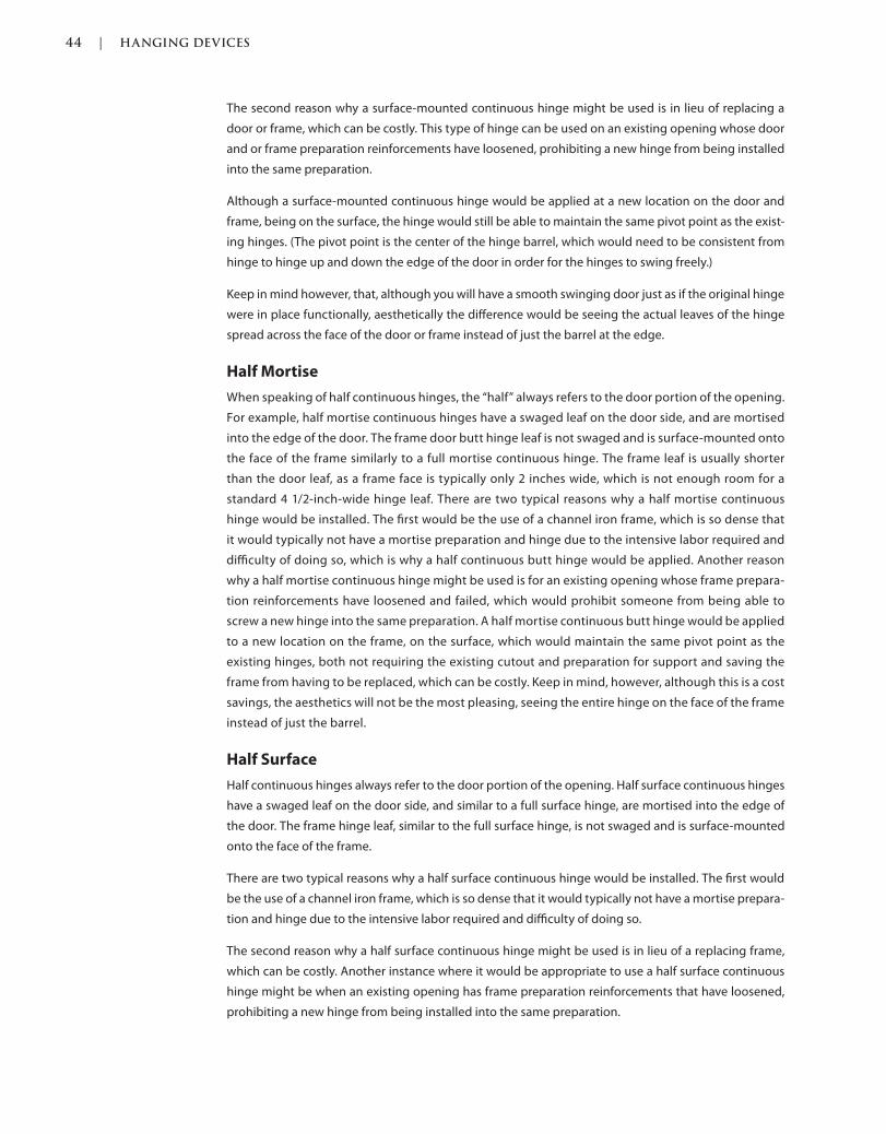
44 | HANGING DEVICES
c01.indd Page 44 03/02/2015 09:18:52:PM
The second reason why a surface-mounted continuous hinge might be used is in lieu of replacing a
door or frame, which can be costly. This type of hinge can be used on an existing opening whose door
and or frame preparation reinforcements have loosened, prohibiting a new hinge from being installed
into the same preparation.
Although a surface-mounted continuous hinge would be applied at a new location on the door and
frame, being on the surface, the hinge would still be able to maintain the same pivot point as the exist-
ing hinges. (The pivot point is the center of the hinge barrel, which would need to be consistent from
hinge to hinge up and down the edge of the door in order for the hinges to swing freely.)
Keep in mind however, that, although you will have a smooth swinging door just as if the original hinge
were in place functionally, aesthetically the difference would be seeing the actual leaves of the hinge
spread across the face of the door or frame instead of just the barrel at the edge.
Half Mortise
When speaking of half continuous hinges, the “half” always refers to the door portion of the opening.
For example, half mortise continuous hinges have a swaged leaf on the door side, and are mortised
into the edge of the door. The frame door butt hinge leaf is not swaged and is surface-mounted onto
the face of the frame similarly to a full mortise continuous hinge. The frame leaf is usually shorter
than the door leaf, as a frame face is typically only 2 inches wide, which is not enough room for a
standard 4 1/2-inch-wide hinge leaf. There are two typical reasons why a half mortise continuous
hinge would be installed. The first would be the use of a channel iron frame, which is so dense that
it would typically not have a mortise preparation and hinge due to the intensive labor required and
difficulty of doing so, which is why a half continuous butt hinge would be applied. Another reason
why a half mortise continuous hinge might be used is for an existing opening whose frame prepara-
tion reinforcements have loosened and failed, which would prohibit someone from being able to
screw a new hinge into the same preparation. A half mortise continuous butt hinge would be applied
to a new location on the frame, on the surface, which would maintain the same pivot point as the
existing hinges, both not requiring the existing cutout and preparation for support and saving the
frame from having to be replaced, which can be costly. Keep in mind, however, although this is a cost
savings, the aesthetics will not be the most pleasing, seeing the entire hinge on the face of the frame
instead of just the barrel.
Half Surface
Half continuous hinges always refer to the door portion of the opening. Half surface continuous hinges
have a swaged leaf on the door side, and similar to a full surface hinge, are mortised into the edge of
the door. The frame hinge leaf, similar to the full surface hinge, is not swaged and is surface-mounted
onto the face of the frame.
There are two typical reasons why a half surface continuous hinge would be installed. The first would
be the use of a channel iron frame, which is so dense that it would typically not have a mortise prepara-
tion and hinge due to the intensive labor required and difficulty of doing so.
The second reason why a half surface continuous hinge might be used is in lieu of a replacing frame,
which can be costly. Another instance where it would be appropriate to use a half surface continuous
hinge might be when an existing opening has frame preparation reinforcements that have loosened,
prohibiting a new hinge from being installed into the same preparation.
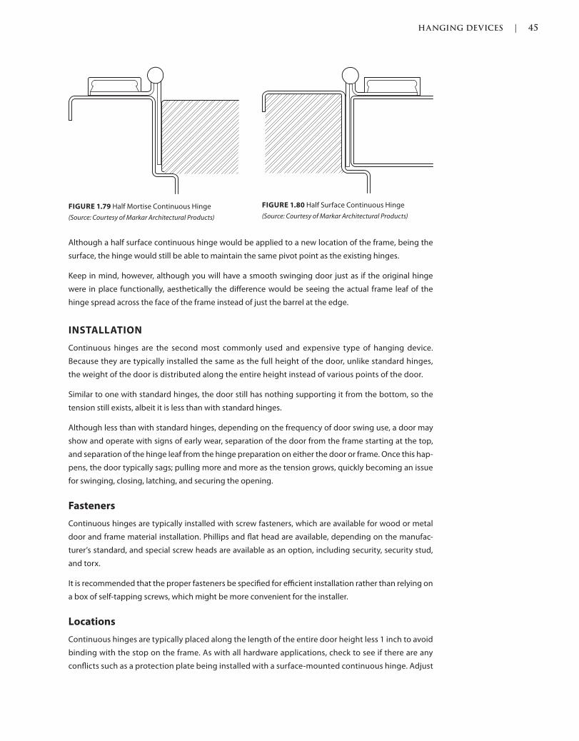
HANGING DEVICES | 45
c01.indd Page 45 03/02/2015 09:18:52:PM
Although a half surface continuous hinge would be applied to a new location of the frame, being the
surface, the hinge would still be able to maintain the same pivot point as the existing hinges.
Keep in mind, however, although you will have a smooth swinging door just as if the original hinge
were in place functionally, aesthetically the difference would be seeing the actual frame leaf of the
hinge spread across the face of the frame instead of just the barrel at the edge.
INSTALLATION
Continuous hinges are the second most commonly used and expensive type of hanging device.
Because they are typically installed the same as the full height of the door, unlike standard hinges,
the weight of the door is distributed along the entire height instead of various points of the door.
Similar to one with standard hinges, the door still has nothing supporting it from the bottom, so the
tension still exists, albeit it is less than with standard hinges.
Although less than with standard hinges, depending on the frequency of door swing use, a door may
show and operate with signs of early wear, separation of the door from the frame starting at the top,
and separation of the hinge leaf from the hinge preparation on either the door or frame. Once this hap-
pens, the door typically sags; pulling more and more as the tension grows, quickly becoming an issue
for swinging, closing, latching, and securing the opening.
Fasteners
Continuous hinges are typically installed with screw fasteners, which are available for wood or metal
door and frame material installation. Phillips and flat head are available, depending on the manufac-
turer’s standard, and special screw heads are available as an option, including security, security stud,
and torx.
It is recommended that the proper fasteners be specified for efficient installation rather than relying on
a box of self-tapping screws, which might be more convenient for the installer.
Locations
Continuous hinges are typically placed along the length of the entire door height less 1 inch to avoid
binding with the stop on the frame. As with all hardware applications, check to see if there are any
conflicts such as a protection plate being installed with a surface-mounted continuous hinge. Adjust
FIGURE 1.79 Half Mortise Continuous Hinge
(Source: Courtesy of Markar Architectural Products)
FIGURE 1.80 Half Surface Continuous Hinge
(Source: Courtesy of Markar Architectural Products)
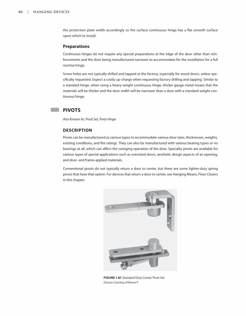
46 | HANGING DEVICES
c01.indd Page 46 03/02/2015 09:18:52:PM
the protection plate width accordingly so the surface continuous hinge has a flat smooth surface
upon which to install.
Preparations
Continuous hinges do not require any special preparations at the edge of the door other than rein-
forcements and the door being manufactured narrower to accommodate for the installation for a full
mortise hinge.
Screw holes are not typically drilled and tapped at the factory, especially for wood doors, unless spe-
cifically requested. Expect a costly up-charge when requesting factory drilling and tapping. Similar to
a standard hinge, when using a heavy weight continuous hinge, thicker gauge metal means that the
materials will be thicker and the door width will be narrower than a door with a standard weight con-
tinuous hinge.
PIVOTS
Also Known As: Pivot Set, Pivot Hinge
DESCRIPTION
Pivots can be manufactured as various types to accommodate various door sizes, thicknesses, weights,
existing conditions, and fire ratings. They can also be manufactured with various bearing types or no
bearings at all, which can affect the swinging operation of the door. Specialty pivots are available for
various types of special applications such as oversized doors, aesthetic design aspects of an opening,
and door- and frame-applied materials.
Conventional pivots do not typically return a door to center, but there are some lighter-duty spring
pivots that have that option. For devices that return a door to center, see Hanging Means, Floor Closers
in this chapter.
FIGURE 1.81 Standard Duty Center Pivot Set
(Source: Courtesy of Rixson®)
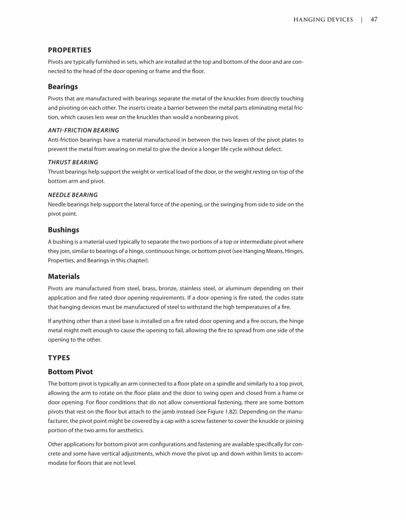
HANGING DEVICES | 47
c01.indd Page 47 03/02/2015 09:18:52:PM
PROPERTIES
Pivots are typically furnished in sets, which are installed at the top and bottom of the door and are con-
nected to the head of the door opening or frame and the floor.
Bearings
Pivots that are manufactured with bearings separate the metal of the knuckles from directly touching
and pivoting on each other. The inserts create a barrier between the metal parts eliminating metal fric-
tion, which causes less wear on the knuckles than would a nonbearing pivot.
ANTIFRICTION BEARING
Anti-friction bearings have a material manufactured in between the two leaves of the pivot plates to
prevent the metal from wearing on metal to give the device a longer life cycle without defect.
THRUST BEARING
Thrust bearings help support the weight or vertical load of the door, or the weight resting on top of the
bottom arm and pivot.
NEEDLE BEARING
Needle bearings help support the lateral force of the opening, or the swinging from side to side on the
pivot point.
Bushings
A bushing is a material used typically to separate the two portions of a top or intermediate pivot where
they join, similar to bearings of a hinge, continuous hinge, or bottom pivot (see Hanging Means, Hinges,
Properties, and Bearings in this chapter).
Materials
Pivots are manufactured from steel, brass, bronze, stainless steel, or aluminum depending on their
application and fire rated door opening requirements. If a door opening is fire rated, the codes state
that hanging devices must be manufactured of steel to withstand the high temperatures of a fire.
If anything other than a steel base is installed on a fire rated door opening and a fire occurs, the hinge
metal might melt enough to cause the opening to fail, allowing the fire to spread from one side of the
opening to the other.
TYPES
Bottom Pivot
The bottom pivot is typically an arm connected to a floor plate on a spindle and similarly to a top pivot,
allowing the arm to rotate on the floor plate and the door to swing open and closed from a frame or
door opening. For floor conditions that do not allow conventional fastening, there are some bottom
pivots that rest on the floor but attach to the jamb instead (see Figure 1.82). Depending on the manu-
facturer, the pivot point might be covered by a cap with a screw fastener to cover the knuckle or joining
portion of the two arms for aesthetics.
Other applications for bottom pivot arm configurations and fastening are available specifically for con-
crete and some have vertical adjustments, which move the pivot up and down within limits to accom-
modate for floors that are not level.

48 | HANGING DEVICES
c01.indd Page 48 03/02/2015 09:18:52:PM
Intermediate Pivot
Offset intermediate pivots are not only recommended to be specified and installed when using a top
and bottom offset pivot, they are required by some manufacturers. Offset intermediate pivots have
the same standard pivot point as a top and bottom pivot set, which is 3/4 inch, which means the pivot
point, or center of the pivoting portion of the pivot, is 3/4 inch from the face of the door and are handed
either left hand or right hand. Intermediate offset pivots are also available in special offset dimensions;
the most common extended offset dimension is 1 1/2 inches, which is typically used to accommodate a
FIGURE 1.84 Intermediate Offset Pivot
(Source: Courtesy of Scott J. Tobias)
FIGURE 1.85 Offset Top Pivot Arm
(Source: Courtesy of Rixson®)
FIGURE 1.82 Offset Top-Mounted Pivot
(Source: Courtesy of Rixson®)
FIGURE 1.83 Floor-Mounted Bottom Offset Pivot
(Source: Courtesy of Scott J. Tobias)
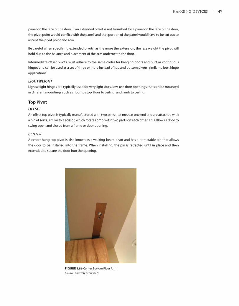
HANGING DEVICES | 49
c01.indd Page 49 03/02/2015 09:18:52:PM
panel on the face of the door. If an extended offset is not furnished for a panel on the face of the door,
the pivot point would conflict with the panel, and that portion of the panel would have to be cut out to
accept the pivot point and arm.
Be careful when specifying extended pivots, as the more the extension, the less weight the pivot will
hold due to the balance and placement of the arm underneath the door.
Intermediate offset pivots must adhere to the same codes for hanging doors and butt or continuous
hinges and can be used as a set of three or more instead of top and bottom pivots, similar to butt hinge
applications.
LIGHTWEIGHT
Lightweight hinges are typically used for very light-duty, low-use door openings that can be mounted
in different mountings such as floor to stop, floor to ceiling, and jamb to ceiling.
Top Pivot
OFFSET
An offset top pivot is typically manufactured with two arms that meet at one end and are attached with
a pin of sorts, similar to a scissor, which rotates or “pivots” two parts on each other. This allows a door to
swing open and closed from a frame or door opening.
CENTER
A center-hung top pivot is also known as a walking-beam pivot and has a retractable pin that allows
the door to be installed into the frame. When installing, the pin is retracted until in place and then
extended to secure the door into the opening.
FIGURE 1.86 Center Bottom Pivot Arm
(Source: Courtesy of Rixson®)
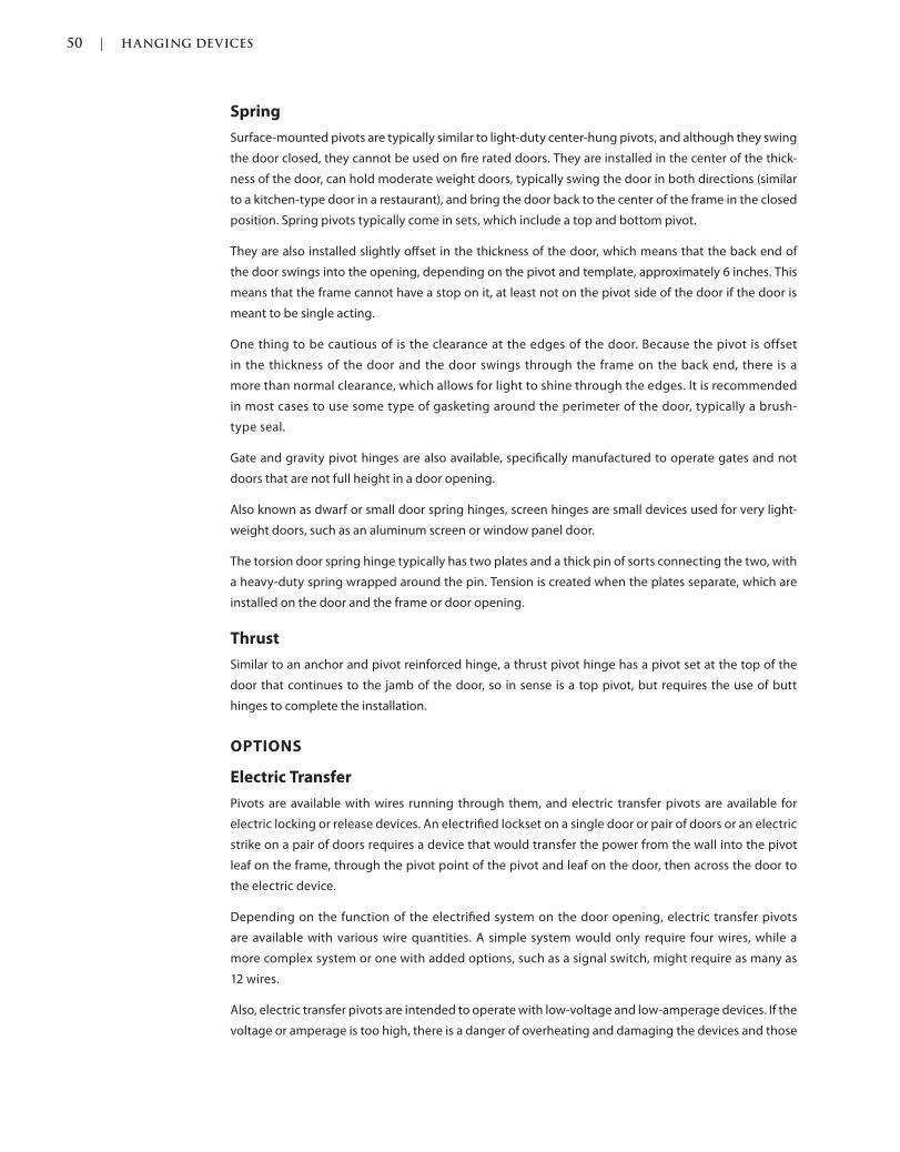
50 | HANGING DEVICES
c01.indd Page 50 03/02/2015 09:18:52:PM
Spring
Surface-mounted pivots are typically similar to light-duty center-hung pivots, and although they swing
the door closed, they cannot be used on fire rated doors. They are installed in the center of the thick-
ness of the door, can hold moderate weight doors, typically swing the door in both directions (similar
to a kitchen-type door in a restaurant), and bring the door back to the center of the frame in the closed
position. Spring pivots typically come in sets, which include a top and bottom pivot.
They are also installed slightly offset in the thickness of the door, which means that the back end of
the door swings into the opening, depending on the pivot and template, approximately 6 inches. This
means that the frame cannot have a stop on it, at least not on the pivot side of the door if the door is
meant to be single acting.
One thing to be cautious of is the clearance at the edges of the door. Because the pivot is offset
in the thickness of the door and the door swings through the frame on the back end, there is a
more than normal clearance, which allows for light to shine through the edges. It is recommended
in most cases to use some type of gasketing around the perimeter of the door, typically a brush-
type seal.
Gate and gravity pivot hinges are also available, specifically manufactured to operate gates and not
doors that are not full height in a door opening.
Also known as dwarf or small door spring hinges, screen hinges are small devices used for very light-
weight doors, such as an aluminum screen or window panel door.
The torsion door spring hinge typically has two plates and a thick pin of sorts connecting the two, with
a heavy-duty spring wrapped around the pin. Tension is created when the plates separate, which are
installed on the door and the frame or door opening.
Thrust
Similar to an anchor and pivot reinforced hinge, a thrust pivot hinge has a pivot set at the top of the
door that continues to the jamb of the door, so in sense is a top pivot, but requires the use of butt
hinges to complete the installation.
OPTIONS
Electric Transfer
Pivots are available with wires running through them, and electric transfer pivots are available for
electric locking or release devices. An electrified lockset on a single door or pair of doors or an electric
strike on a pair of doors requires a device that would transfer the power from the wall into the pivot
leaf on the frame, through the pivot point of the pivot and leaf on the door, then across the door to
the electric device.
Depending on the function of the electrified system on the door opening, electric transfer pivots
are available with various wire quantities. A simple system would only require four wires, while a
more complex system or one with added options, such as a signal switch, might require as many as
12 wires.
Also, electric transfer pivots are intended to operate with low-voltage and low-amperage devices. If the
voltage or amperage is too high, there is a danger of overheating and damaging the devices and those
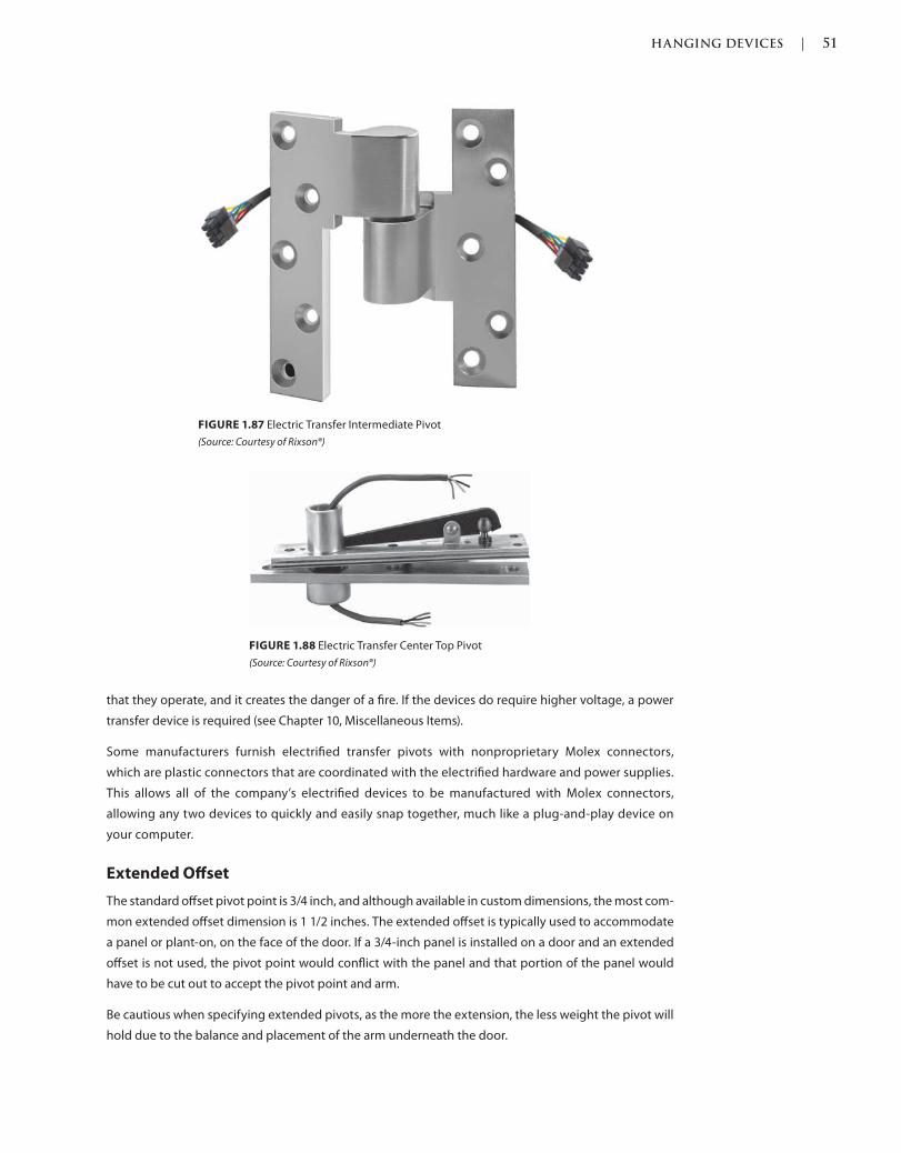
HANGING DEVICES | 51
c01.indd Page 51 03/02/2015 09:18:52:PM
that they operate, and it creates the danger of a fire. If the devices do require higher voltage, a power
transfer device is required (see Chapter 10, Miscellaneous Items).
Some manufacturers furnish electrified transfer pivots with nonproprietary Molex connectors,
which are plastic connectors that are coordinated with the electrified hardware and power supplies.
This allows all of the company’s electrified devices to be manufactured with Molex connectors,
allowing any two devices to quickly and easily snap together, much like a plug-and-play device on
your computer.
Extended Offset
The standard offset pivot point is 3/4 inch, and although available in custom dimensions, the most com-
mon extended offset dimension is 1 1/2 inches. The extended offset is typically used to accommodate
a panel or plant-on, on the face of the door. If a 3/4-inch panel is installed on a door and an extended
offset is not used, the pivot point would conflict with the panel and that portion of the panel would
have to be cut out to accept the pivot point and arm.
Be cautious when specifying extended pivots, as the more the extension, the less weight the pivot will
hold due to the balance and placement of the arm underneath the door.
FIGURE 1.87 Electric Transfer Intermediate Pivot
(Source: Courtesy of Rixson®)
FIGURE 1.88 Electric Transfer Center Top Pivot
(Source: Courtesy of Rixson®)
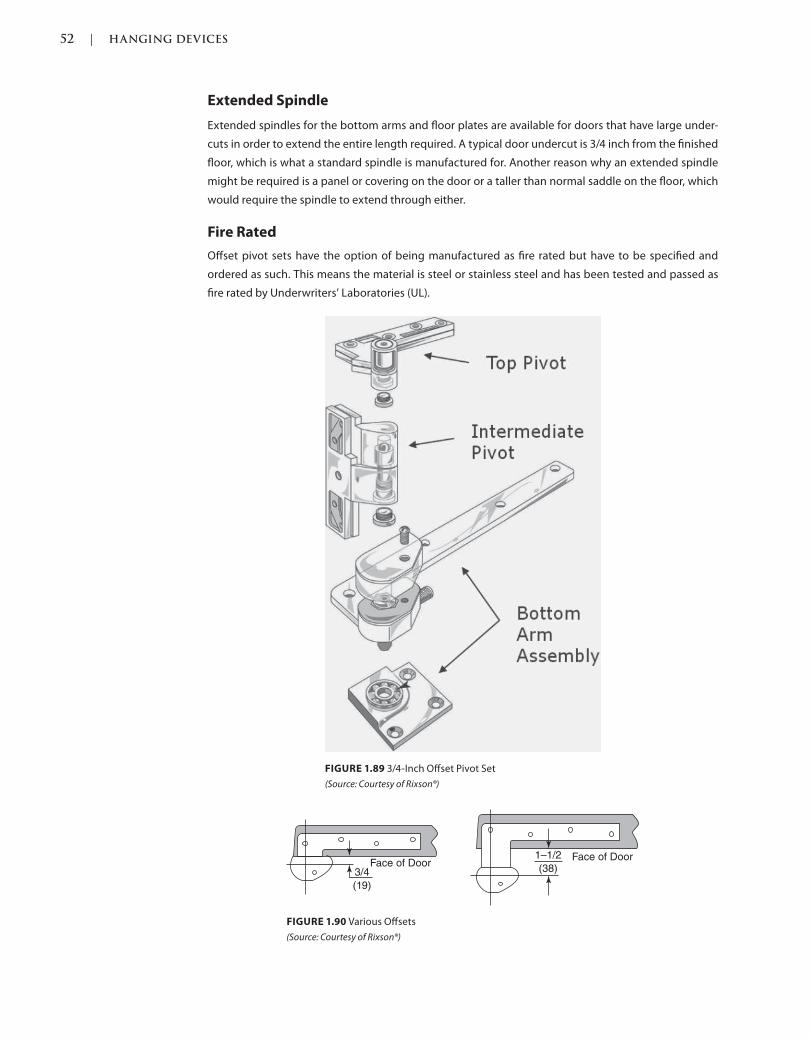
52 | HANGING DEVICES
c01.indd Page 52 03/02/2015 09:18:52:PM
Extended Spindle
Extended spindles for the bottom arms and floor plates are available for doors that have large under-
cuts in order to extend the entire length required. A typical door undercut is 3/4 inch from the finished
floor, which is what a standard spindle is manufactured for. Another reason why an extended spindle
might be required is a panel or covering on the door or a taller than normal saddle on the floor, which
would require the spindle to extend through either.
Fire Rated
Offset pivot sets have the option of being manufactured as fire rated but have to be specified and
ordered as such. This means the material is steel or stainless steel and has been tested and passed as
fire rated by Underwriters’ Laboratories (UL).
FIGURE 1.89 3/4-Inch Offset Pivot Set
(Source: Courtesy of Rixson®)
FIGURE 1.90 Various Offsets
(Source: Courtesy of Rixson®)
Face of Door3/4
(19)
Face of Door1–1/2
(38)
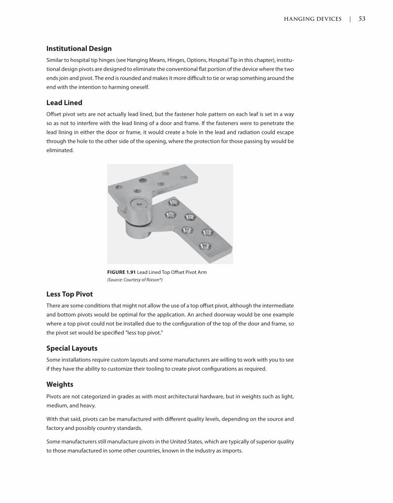
HANGING DEVICES | 53
c01.indd Page 53 03/02/2015 09:18:52:PM
Institutional Design
Similar to hospital tip hinges (see Hanging Means, Hinges, Options, Hospital Tip in this chapter), institu-
tional design pivots are designed to eliminate the conventional flat portion of the device where the two
ends join and pivot. The end is rounded and makes it more difficult to tie or wrap something around the
end with the intention to harming oneself.
Lead Lined
Offset pivot sets are not actually lead lined, but the fastener hole pattern on each leaf is set in a way
so as not to interfere with the lead lining of a door and frame. If the fasteners were to penetrate the
lead lining in either the door or frame, it would create a hole in the lead and radiation could escape
through the hole to the other side of the opening, where the protection for those passing by would be
eliminated.
Less Top Pivot
There are some conditions that might not allow the use of a top offset pivot, although the intermediate
and bottom pivots would be optimal for the application. An arched doorway would be one example
where a top pivot could not be installed due to the configuration of the top of the door and frame, so
the pivot set would be specified “less top pivot.”
Special Layouts
Some installations require custom layouts and some manufacturers are willing to work with you to see
if they have the ability to customize their tooling to create pivot configurations as required.
Weights
Pivots are not categorized in grades as with most architectural hardware, but in weights such as light,
medium, and heavy.
With that said, pivots can be manufactured with different quality levels, depending on the source and
factory and possibly country standards.
Some manufacturers still manufacture pivots in the United States, which are typically of superior quality
to those manufactured in some other countries, known in the industry as imports.
FIGURE 1.91 Lead Lined Top Offset Pivot Arm
(Source: Courtesy of Rixson®)
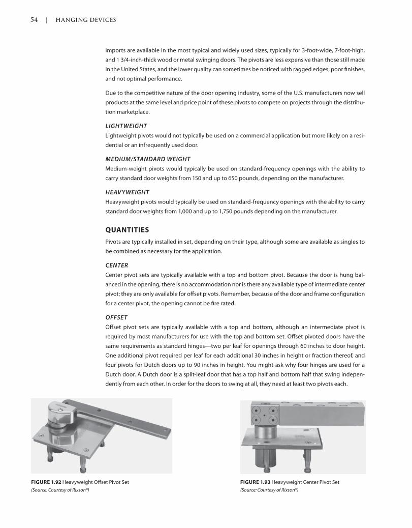
54 | HANGING DEVICES
c01.indd Page 54 03/02/2015 09:18:52:PM
Imports are available in the most typical and widely used sizes, typically for 3-foot-wide, 7-foot-high,
and 1 3/4-inch-thick wood or metal swinging doors. The pivots are less expensive than those still made
in the United States, and the lower quality can sometimes be noticed with ragged edges, poor finishes,
and not optimal performance.
Due to the competitive nature of the door opening industry, some of the U.S. manufacturers now sell
products at the same level and price point of these pivots to compete on projects through the distribu-
tion marketplace.
LIGHTWEIGHT
Lightweight pivots would not typically be used on a commercial application but more likely on a resi-
dential or an infrequently used door.
MEDIUM/STANDARD WEIGHT
Medium-weight pivots would typically be used on standard-frequency openings with the ability to
carry standard door weights from 150 and up to 650 pounds, depending on the manufacturer.
HEAVYWEIGHT
Heavyweight pivots would typically be used on standard-frequency openings with the ability to carry
standard door weights from 1,000 and up to 1,750 pounds depending on the manufacturer.
QUANTITIES
Pivots are typically installed in set, depending on their type, although some are available as singles to
be combined as necessary for the application.
CENTER
Center pivot sets are typically available with a top and bottom pivot. Because the door is hung bal-
anced in the opening, there is no accommodation nor is there any available type of intermediate center
pivot; they are only available for offset pivots. Remember, because of the door and frame configuration
for a center pivot, the opening cannot be fire rated.
OFFSET
Offset pivot sets are typically available with a top and bottom, although an intermediate pivot is
required by most manufacturers for use with the top and bottom set. Offset pivoted doors have the
same requirements as standard hinges—two per leaf for openings through 60 inches to door height.
One additional pivot required per leaf for each additional 30 inches in height or fraction thereof, and
four pivots for Dutch doors up to 90 inches in height. You might ask why four hinges are used for a
Dutch door. A Dutch door is a split-leaf door that has a top half and bottom half that swing indepen-
dently from each other. In order for the doors to swing at all, they need at least two pivots each.
FIGURE 1.92 Heavyweight Offset Pivot Set
(Source: Courtesy of Rixson®)
FIGURE 1.93 Heavyweight Center Pivot Set
(Source: Courtesy of Rixson®)
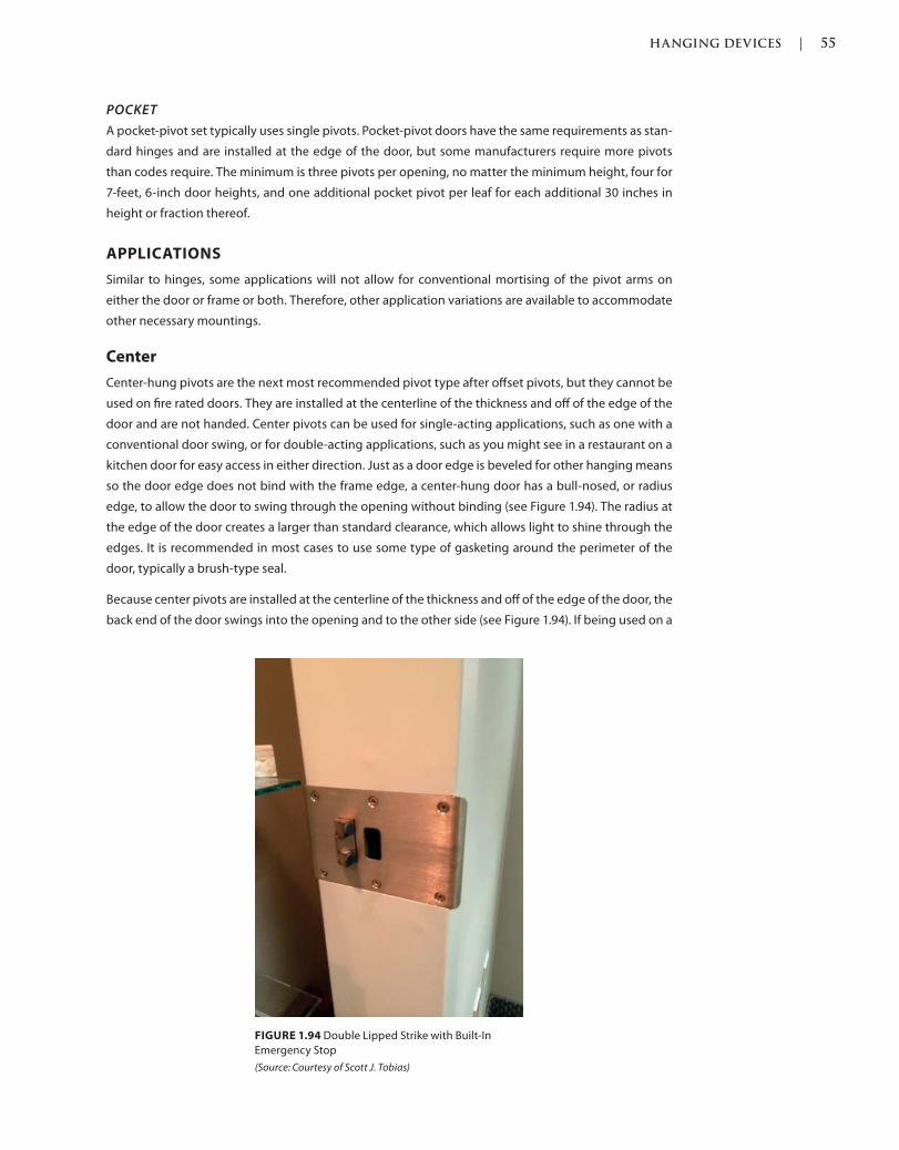
HANGING DEVICES | 55
c01.indd Page 55 03/02/2015 09:18:52:PM
A pocket-pivot set typically uses single pivots. Pocket-pivot doors have the same requirements as stan-
dard hinges and are installed at the edge of the door, but some manufacturers require more pivots
than codes require. The minimum is three pivots per opening, no matter the minimum height, four for
7-feet, 6-inch door heights, and one additional pocket pivot per leaf for each additional 30 inches in
height or fraction thereof.
APPLICATIONS
Similar to hinges, some applications will not allow for conventional mortising of the pivot arms on
either the door or frame or both. Therefore, other application variations are available to accommodate
other necessary mountings.
Center
Center-hung pivots are the next most recommended pivot type after offset pivots, but they cannot be
used on fire rated doors. They are installed at the centerline of the thickness and off of the edge of the
door and are not handed. Center pivots can be used for single-acting applications, such as one with a
conventional door swing, or for double-acting applications, such as you might see in a restaurant on a
kitchen door for easy access in either direction. Just as a door edge is beveled for other hanging means
so the door edge does not bind with the frame edge, a center-hung door has a bull-nosed, or radius
edge, to allow the door to swing through the opening without binding (see Figure 1.94). The radius at
the edge of the door creates a larger than standard clearance, which allows light to shine through the
edges. It is recommended in most cases to use some type of gasketing around the perimeter of the
door, typically a brush-type seal.
Because center pivots are installed at the centerline of the thickness and off of the edge of the door, the
back end of the door swings into the opening and to the other side (see Figure 1.94). If being used on a
FIGURE 1.94 Double Lipped Strike with Built-In
Emergency Stop
(Source: Courtesy of Scott J. Tobias)
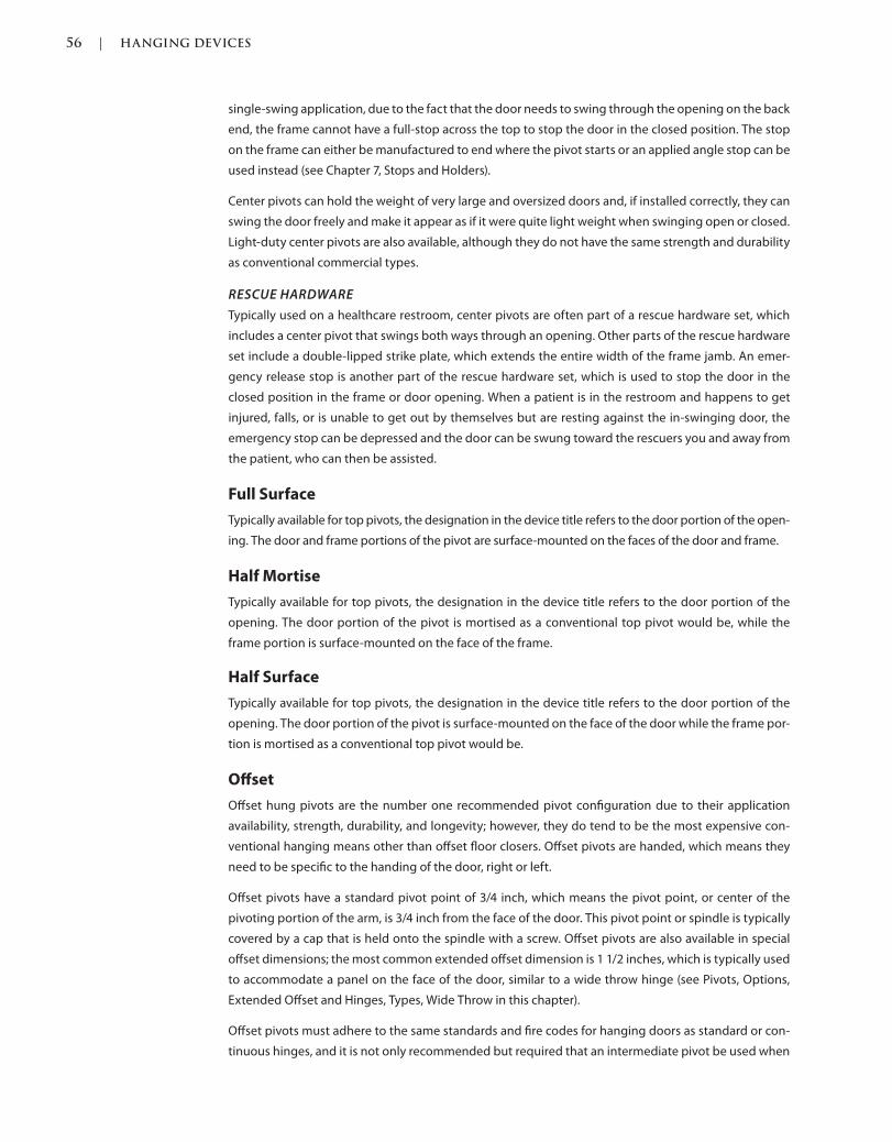
56 | HANGING DEVICES
c01.indd Page 56 03/02/2015 09:18:52:PM
single-swing application, due to the fact that the door needs to swing through the opening on the back
end, the frame cannot have a full-stop across the top to stop the door in the closed position. The stop
on the frame can either be manufactured to end where the pivot starts or an applied angle stop can be
used instead (see Chapter 7, Stops and Holders).
Center pivots can hold the weight of very large and oversized doors and, if installed correctly, they can
swing the door freely and make it appear as if it were quite light weight when swinging open or closed.
Light-duty center pivots are also available, although they do not have the same strength and durability
as conventional commercial types.
RESCUE HARDWARE
Typically used on a healthcare restroom, center pivots are often part of a rescue hardware set, which
includes a center pivot that swings both ways through an opening. Other parts of the rescue hardware
set include a double-lipped strike plate, which extends the entire width of the frame jamb. An emer-
gency release stop is another part of the rescue hardware set, which is used to stop the door in the
closed position in the frame or door opening. When a patient is in the restroom and happens to get
injured, falls, or is unable to get out by themselves but are resting against the in-swinging door, the
emergency stop can be depressed and the door can be swung toward the rescuers you and away from
the patient, who can then be assisted.
Full Surface
Typically available for top pivots, the designation in the device title refers to the door portion of the open-
ing. The door and frame portions of the pivot are surface-mounted on the faces of the door and frame.
Half Mortise
Typically available for top pivots, the designation in the device title refers to the door portion of the
opening. The door portion of the pivot is mortised as a conventional top pivot would be, while the
frame portion is surface-mounted on the face of the frame.
Half Surface
Typically available for top pivots, the designation in the device title refers to the door portion of the
opening. The door portion of the pivot is surface-mounted on the face of the door while the frame por-
tion is mortised as a conventional top pivot would be.
Offset
Offset hung pivots are the number one recommended pivot configuration due to their application
availability, strength, durability, and longevity; however, they do tend to be the most expensive con-
ventional hanging means other than offset floor closers. Offset pivots are handed, which means they
need to be specific to the handing of the door, right or left.
Offset pivots have a standard pivot point of 3/4 inch, which means the pivot point, or center of the
pivoting portion of the arm, is 3/4 inch from the face of the door. This pivot point or spindle is typically
covered by a cap that is held onto the spindle with a screw. Offset pivots are also available in special
offset dimensions; the most common extended offset dimension is 1 1/2 inches, which is typically used
to accommodate a panel on the face of the door, similar to a wide throw hinge (see Pivots, Options,
Extended Offset and Hinges, Types, Wide Throw in this chapter).
Offset pivots must adhere to the same standards and fire codes for hanging doors as standard or con-
tinuous hinges, and it is not only recommended but required that an intermediate pivot be used when
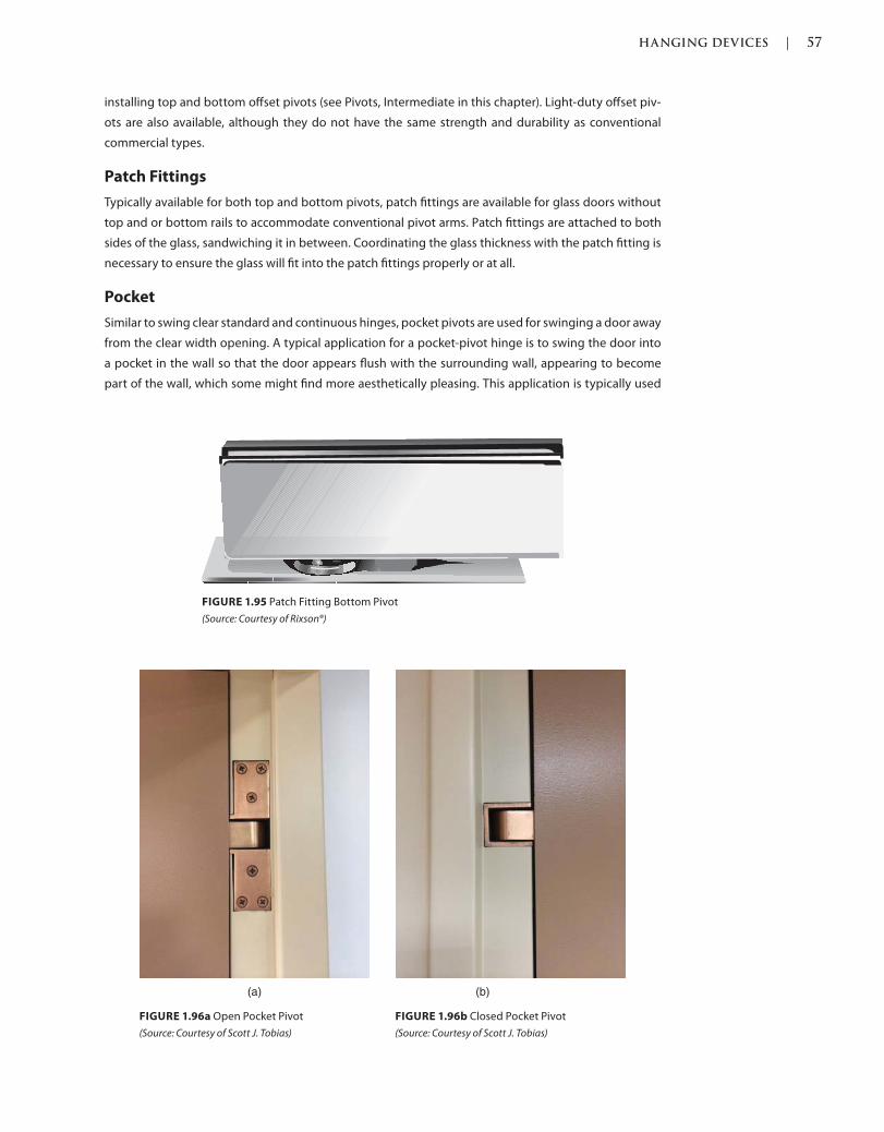
HANGING DEVICES | 57
c01.indd Page 57 03/02/2015 09:18:52:PM
installing top and bottom offset pivots (see Pivots, Intermediate in this chapter). Light-duty offset piv-
ots are also available, although they do not have the same strength and durability as conventional
commercial types.
Patch Fittings
Typically available for both top and bottom pivots, patch fittings are available for glass doors without
top and or bottom rails to accommodate conventional pivot arms. Patch fittings are attached to both
sides of the glass, sandwiching it in between. Coordinating the glass thickness with the patch fitting is
necessary to ensure the glass will fit into the patch fittings properly or at all.
Similar to swing clear standard and continuous hinges, pocket pivots are used for swinging a door away
from the clear width opening. A typical application for a pocket-pivot hinge is to swing the door into
a pocket in the wall so that the door appears flush with the surrounding wall, appearing to become
part of the wall, which some might find more aesthetically pleasing. This application is typically used
FIGURE 1.95 Patch Fitting Bottom Pivot
(Source: Courtesy of Rixson®)
FIGURE 1.96a Open Pocket Pivot
(Source: Courtesy of Scott J. Tobias)
(a) (b)
FIGURE 1.96b Closed Pocket Pivot
(Source: Courtesy of Scott J. Tobias)
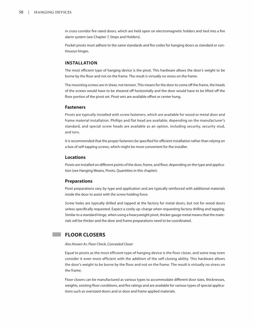
58 | HANGING DEVICES
c01.indd Page 58 03/02/2015 09:18:52:PM
in cross-corridor fire rated doors, which are held open on electromagnetic holders and tied into a fire
alarm system (see Chapter 7, Stops and Holders).
Pocket pivots must adhere to the same standards and fire codes for hanging doors as standard or con-
tinuous hinges.
INSTALLATION
The most efficient type of hanging device is the pivot. This hardware allows the door’s weight to be
borne by the floor and not on the frame. The result is virtually no stress on the frame.
The mounting screws are in shear, not tension. This means for the door to come off the frame, the heads
of the screws would have to be sheared off horizontally and the door would have to be lifted off the
floor portion of the pivot set. Pivot sets are available offset or center hung.
Fasteners
Pivots are typically installed with screw fasteners, which are available for wood or metal door and
frame material installation. Phillips and flat head are available, depending on the manufacturer’s
standard, and special screw heads are available as an option, including security, security stud,
and torx.
It is recommended that the proper fasteners be specified for efficient installation rather than relying on
a box of self-tapping screws, which might be more convenient for the installer.
Locations
Pivots are installed on different points of the door, frame, and floor, depending on the type and applica-
tion (see Hanging Means, Pivots, Quantities in this chapter).
Preparations
Pivot preparations vary by type and application and are typically reinforced with additional materials
inside the door to assist with the screw holding force.
Screw holes are typically drilled and tapped at the factory for metal doors, but not for wood doors
unless specifically requested. Expect a costly up-charge when requesting factory drilling and tapping.
Similar to a standard hinge, when using a heavyweight pivot, thicker gauge metal means that the mate-
rials will be thicker and the door and frame preparations need to be coordinated.
FLOOR CLOSERS
Also Known As: Floor Check, Concealed Closer
Equal to pivots as the most efficient type of hanging device is the floor closer, and some may even
consider it even more efficient with the addition of the self-closing ability. This hardware allows
the door’s weight to be borne by the floor and not on the frame. The result is virtually no stress on
the frame.
Floor closers can be manufactured as various types to accommodate different door sizes, thicknesses,
weights, existing floor conditions, and fire ratings and are available for various types of special applica-
tions such as oversized doors and or door and frame applied materials.
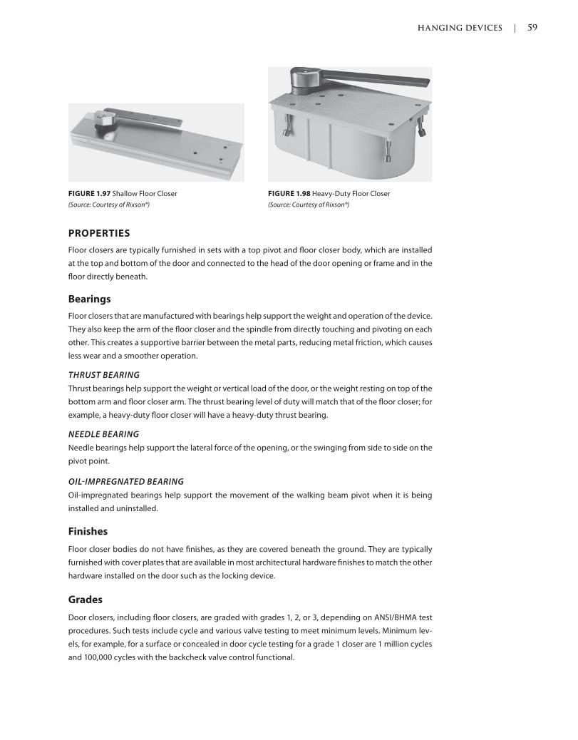
HANGING DEVICES | 59
c01.indd Page 59 03/02/2015 09:18:52:PM
PROPERTIES
Floor closers are typically furnished in sets with a top pivot and floor closer body, which are installed
at the top and bottom of the door and connected to the head of the door opening or frame and in the
floor directly beneath.
Bearings
Floor closers that are manufactured with bearings help support the weight and operation of the device.
They also keep the arm of the floor closer and the spindle from directly touching and pivoting on each
other. This creates a supportive barrier between the metal parts, reducing metal friction, which causes
less wear and a smoother operation.
THRUST BEARING
Thrust bearings help support the weight or vertical load of the door, or the weight resting on top of the
bottom arm and floor closer arm. The thrust bearing level of duty will match that of the floor closer; for
example, a heavy-duty floor closer will have a heavy-duty thrust bearing.
NEEDLE BEARING
Needle bearings help support the lateral force of the opening, or the swinging from side to side on the
pivot point.
OILIMPREGNATED BEARING
Oil-impregnated bearings help support the movement of the walking beam pivot when it is being
installed and uninstalled.
Finishes
Floor closer bodies do not have finishes, as they are covered beneath the ground. They are typically
furnished with cover plates that are available in most architectural hardware finishes to match the other
hardware installed on the door such as the locking device.
Grades
Door closers, including floor closers, are graded with grades 1, 2, or 3, depending on ANSI/BHMA test
procedures. Such tests include cycle and various valve testing to meet minimum levels. Minimum lev-
els, for example, for a surface or concealed in door cycle testing for a grade 1 closer are 1 million cycles
and 100,000 cycles with the backcheck valve control functional.
FIGURE 1.97 Shallow Floor Closer
(Source: Courtesy of Rixson®)
FIGURE 1.98 Heavy-Duty Floor Closer
(Source: Courtesy of Rixson®)

60 | HANGING DEVICES
c01.indd Page 60 03/02/2015 09:18:52:PM
Materials
The internal parts and decorative cover plates of floor closers are manufactured from various met-
als, depending on the manufacturer. The arms are manufactured from brass, bronze, stainless steel, or
steel, depending on their application and fire rated door opening requirements. If a door opening is
fire rated, the codes state that hanging devices must be manufactured of steel to withstand the high
temperatures of a fire.
If anything other than a steel base is installed on a fire rated door opening and a fire occurs, the hinge
metal might melt enough to cause the opening to fail, allowing the fire to spread from one side of the
opening to the other.
Springs
CAM
A cam action closer operates by a twisting motion, which pushes and pulls the springs that operate
with the closer opening and closing cycles. A cam action closer is different from a standard closer
where a standard closer does not have a twisting part, but rather hydraulic fluid that flows back and
forth through the device, pushing and pulling the parts that are required to move the closer through
the cycles.
TORSION
A torsion spring is a wound spring, where the tension is in the wind rather than in compressing or
squeezing. The spring is wound and has tension in the same direction as the door swing, which helps
with efficiency and operation of the door.
COMPRESSION
A compression spring is compressed or squeezed and released to create the movement necessary
to close a door and is not as efficient as a torsion spring (see Hanging Means, Floor Closers, Options,
Springs in this chapter).
Stops
Some floor closers have built-in stops, which hard-stop the door at a set degree of opening. The open-
ing degree is typically limited and depends on the manufacturer’s availability.
Valves
Floor closers are manufactured with various valves to assist with optimizing the closing and latching
speeds and forces. These valves act in cycles of the door opening and closing.
BACKCHECK
Backcheck valves allow for adjustment to the opening force past about 65 degrees of the door in the
open position to give the door less resistance, making it easier to push open.
CLOSING SPEED
Closing speed valves allow for adjustment of the closing speed cycle. This is the speed once initially
released if the device has no delayed action option (see Hanging Means, Floor Closers, Options in this
chapter) or once the delayed action has completed, and affects the closing up until about 15 degrees
of the closed position.
LATCH SPEED
Latch speed valves allow for adjustment to the latching speed cycle. This is the speed once past the
closing speed cycle and gives the door enough force and power to clear any of the locking device
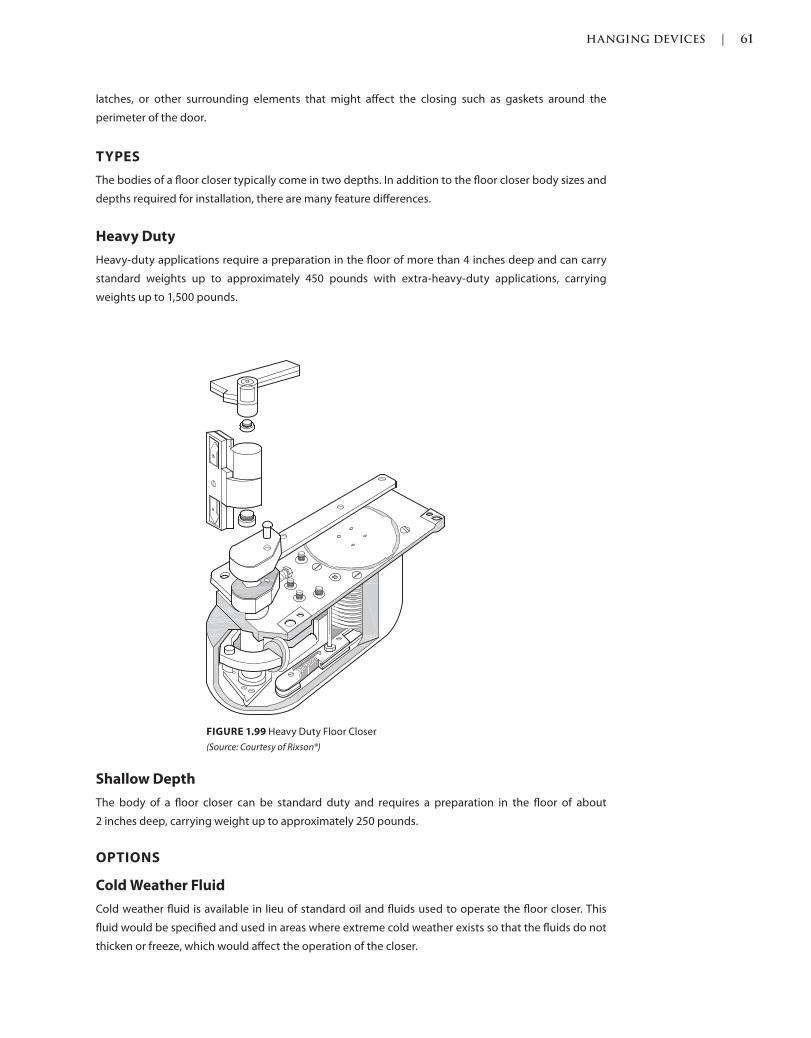
HANGING DEVICES | 61
c01.indd Page 61 03/02/2015 09:18:52:PM
latches, or other surrounding elements that might affect the closing such as gaskets around the
perimeter of the door.
TYPES
The bodies of a floor closer typically come in two depths. In addition to the floor closer body sizes and
depths required for installation, there are many feature differences.
Heavy Duty
Heavy-duty applications require a preparation in the floor of more than 4 inches deep and can carry
standard weights up to approximately 450 pounds with extra-heavy-duty applications, carrying
weights up to 1,500 pounds.
Shallow Depth
The body of a floor closer can be standard duty and requires a preparation in the floor of about
2 inches deep, carrying weight up to approximately 250 pounds.
OPTIONS
Cold Weather Fluid
Cold weather fluid is available in lieu of standard oil and fluids used to operate the floor closer. This
fluid would be specified and used in areas where extreme cold weather exists so that the fluids do not
thicken or freeze, which would affect the operation of the closer.
FIGURE 1.99 Heavy Duty Floor Closer
(Source: Courtesy of Rixson®)
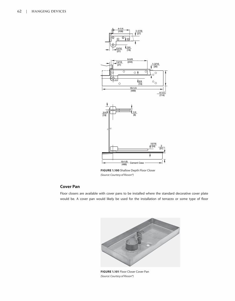
62 | HANGING DEVICES
c01.indd Page 62 03/02/2015 09:18:52:PM
Cover Pan
Floor closers are available with cover pans to be installed where the standard decorative cover plate
would be. A cover pan would likely be used for the installation of terrazzo or some type of floor
FIGURE 1.101 Floor Closer Cover Pan
(Source: Courtesy of Rixson®)
FIGURE 1.100 Shallow Depth Floor Closer
(Source: Courtesy of Rixson®)
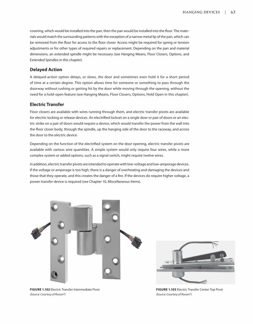
HANGING DEVICES | 63
c01.indd Page 63 03/02/2015 09:18:52:PM
covering, which would be installed into the pan, then the pan would be installed into the floor. The mate-
rials would match the surrounding patterns with the exception of a narrow metal lip of the pan, which can
be removed from the floor for access to the floor closer. Access might be required for spring or tension
adjustments or for other types of required repairs or replacement. Depending on the pan and material
dimensions, an extended spindle might be necessary (see Hanging Means, Floor Closers, Options, and
Extended Spindles in this chapter).
Delayed Action
A delayed-action option delays, or slows, the door and sometimes even hold it for a short period
of time at a certain degree. This option allows time for someone or something to pass through the
doorway without rushing or getting hit by the door while moving through the opening, without the
need for a hold-open feature (see Hanging Means, Floor Closers, Options, Hold Open in this chapter).
Electric Transfer
Floor closers are available with wires running through them, and electric transfer pivots are available
for electric locking or release devices. An electrified lockset on a single door or pair of doors or an elec-
tric strike on a pair of doors would require a device, which would transfer the power from the wall into
the floor closer body, through the spindle, up the hanging side of the door to the raceway, and across
the door to the electric device.
Depending on the function of the electrified system on the door opening, electric transfer pivots are
available with various wire quantities. A simple system would only require four wires, while a more
complex system or added options, such as a signal switch, might require twelve wires.
In addition, electric transfer pivots are intended to operate with low-voltage and low-amperage devices.
If the voltage or amperage is too high, there is a danger of overheating and damaging the devices and
those that they operate, and this creates the danger of a fire. If the devices do require higher voltage, a
power transfer device is required (see Chapter 10, Miscellaneous Items).
FIGURE 1.102 Electric Transfer Intermediate Pivot
(Source: Courtesy of Rixson®)
FIGURE 1.103 Electric Transfer Center Top Pivot
(Source: Courtesy of Rixson®)
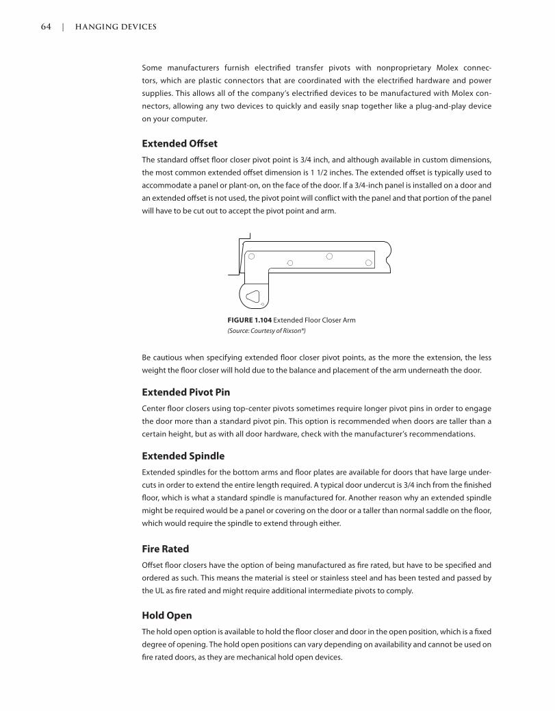
64 | HANGING DEVICES
c01.indd Page 64 03/02/2015 09:18:52:PM
Some manufacturers furnish electrified transfer pivots with nonproprietary Molex connec-
tors, which are plastic connectors that are coordinated with the electrified hardware and power
supplies. This allows all of the company’s electrified devices to be manufactured with Molex con-
nectors, allowing any two devices to quickly and easily snap together like a plug-and-play device
on your computer.
Extended Offset
The standard offset floor closer pivot point is 3/4 inch, and although available in custom dimensions,
the most common extended offset dimension is 1 1/2 inches. The extended offset is typically used to
accommodate a panel or plant-on, on the face of the door. If a 3/4-inch panel is installed on a door and
an extended offset is not used, the pivot point will conflict with the panel and that portion of the panel
will have to be cut out to accept the pivot point and arm.
Be cautious when specifying extended floor closer pivot points, as the more the extension, the less
weight the floor closer will hold due to the balance and placement of the arm underneath the door.
Extended Pivot Pin
Center floor closers using top-center pivots sometimes require longer pivot pins in order to engage
the door more than a standard pivot pin. This option is recommended when doors are taller than a
certain height, but as with all door hardware, check with the manufacturer’s recommendations.
Extended Spindle
Extended spindles for the bottom arms and floor plates are available for doors that have large under-
cuts in order to extend the entire length required. A typical door undercut is 3/4 inch from the finished
floor, which is what a standard spindle is manufactured for. Another reason why an extended spindle
might be required would be a panel or covering on the door or a taller than normal saddle on the floor,
which would require the spindle to extend through either.
Fire Rated
Offset floor closers have the option of being manufactured as fire rated, but have to be specified and
ordered as such. This means the material is steel or stainless steel and has been tested and passed by
the UL as fire rated and might require additional intermediate pivots to comply.
Hold Open
The hold open option is available to hold the floor closer and door in the open position, which is a fixed
degree of opening. The hold open positions can vary depending on availability and cannot be used on
fire rated doors, as they are mechanical hold open devices.
FIGURE 1.104 Extended Floor Closer Arm
(Source: Courtesy of Rixson®)
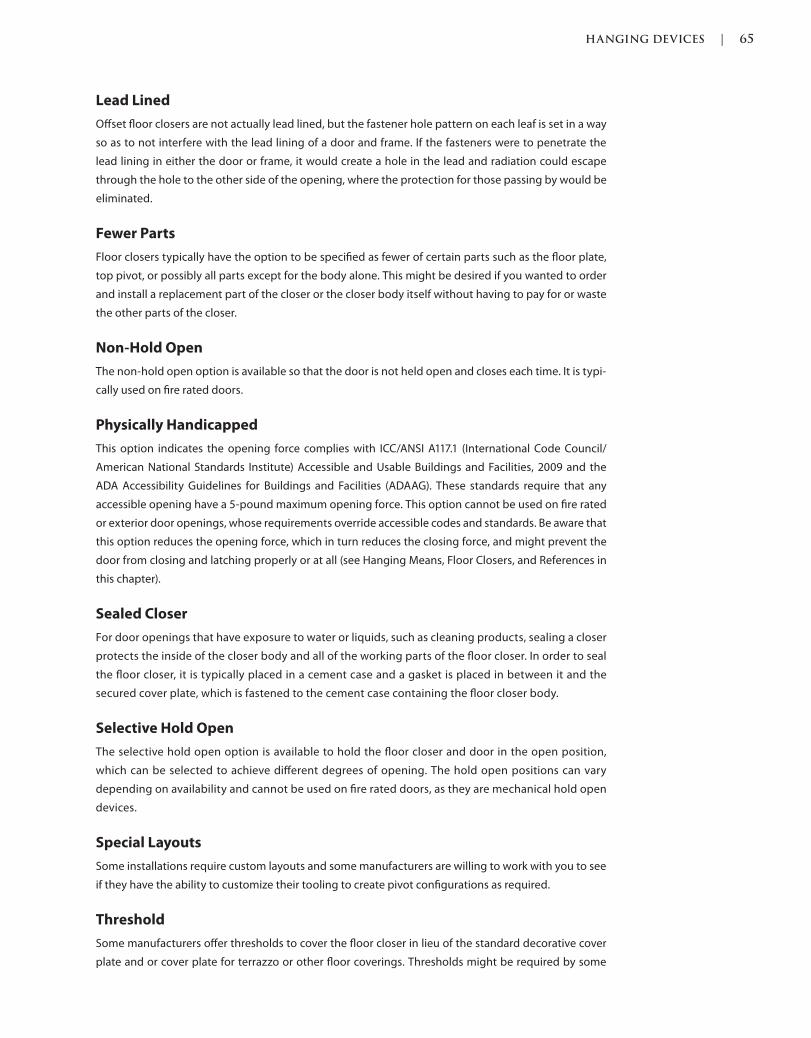
HANGING DEVICES | 65
c01.indd Page 65 03/02/2015 09:18:52:PM
Lead Lined
Offset floor closers are not actually lead lined, but the fastener hole pattern on each leaf is set in a way
so as to not interfere with the lead lining of a door and frame. If the fasteners were to penetrate the
lead lining in either the door or frame, it would create a hole in the lead and radiation could escape
through the hole to the other side of the opening, where the protection for those passing by would be
eliminated.
Fewer Parts
Floor closers typically have the option to be specified as fewer of certain parts such as the floor plate,
top pivot, or possibly all parts except for the body alone. This might be desired if you wanted to order
and install a replacement part of the closer or the closer body itself without having to pay for or waste
the other parts of the closer.
Non-Hold Open
The non-hold open option is available so that the door is not held open and closes each time. It is typi-
cally used on fire rated doors.
Physically Handicapped
This option indicates the opening force complies with ICC/ANSI A117.1 (International Code Council/
American National Standards Institute) Accessible and Usable Buildings and Facilities, 2009 and the
ADA Accessibility Guidelines for Buildings and Facilities (ADAAG). These standards require that any
accessible opening have a 5-pound maximum opening force. This option cannot be used on fire rated
or exterior door openings, whose requirements override accessible codes and standards. Be aware that
this option reduces the opening force, which in turn reduces the closing force, and might prevent the
door from closing and latching properly or at all (see Hanging Means, Floor Closers, and References in
this chapter).
Sealed Closer
For door openings that have exposure to water or liquids, such as cleaning products, sealing a closer
protects the inside of the closer body and all of the working parts of the floor closer. In order to seal
the floor closer, it is typically placed in a cement case and a gasket is placed in between it and the
secured cover plate, which is fastened to the cement case containing the floor closer body.
Selective Hold Open
The selective hold open option is available to hold the floor closer and door in the open position,
which can be selected to achieve different degrees of opening. The hold open positions can vary
depending on availability and cannot be used on fire rated doors, as they are mechanical hold open
devices.
Special Layouts
Some installations require custom layouts and some manufacturers are willing to work with you to see
if they have the ability to customize their tooling to create pivot configurations as required.
Threshold
Some manufacturers offer thresholds to cover the floor closer in lieu of the standard decorative cover
plate and or cover plate for terrazzo or other floor coverings. Thresholds might be required by some
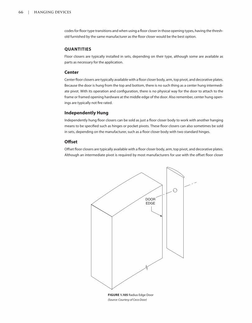
66 | HANGING DEVICES
c01.indd Page 66 03/02/2015 09:18:52:PM
codes for floor type transitions and when using a floor closer in those opening types, having the thresh-
old furnished by the same manufacturer as the floor closer would be the best option.
QUANTITIES
Floor closers are typically installed in sets, depending on their type, although some are available as
parts as necessary for the application.
Center
Center floor closers are typically available with a floor closer body, arm, top pivot, and decorative plates.
Because the door is hung from the top and bottom, there is no such thing as a center hung intermedi-
ate pivot. With its operation and configuration, there is no physical way for the door to attach to the
frame or framed opening hardware at the middle edge of the door. Also remember, center hung open-
ings are typically not fire rated.
Independently Hung
Independently hung floor closers can be sold as just a floor closer body to work with another hanging
means to be specified such as hinges or pocket pivots. These floor closers can also sometimes be sold
in sets, depending on the manufacturer, such as a floor closer body with two standard hinges.
Offset
Offset floor closers are typically available with a floor closer body, arm, top pivot, and decorative plates.
Although an intermediate pivot is required by most manufacturers for use with the offset floor closer
FIGURE 1.105 Radius Edge Door
(Source: Courtesy of Ceco Door)
DOOR
EDGE
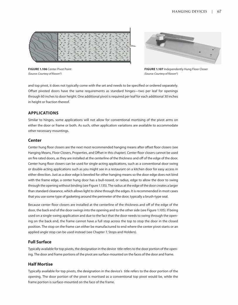
HANGING DEVICES | 67
c01.indd Page 67 03/02/2015 09:18:52:PM
and top pivot, it does not typically come with the set and needs to be specified or ordered separately.
Offset pivoted doors have the same requirements as standard hinges—two per leaf for openings
through 60 inches to door height. One additional pivot is required per leaf for each additional 30 inches
in height or fraction thereof.
APPLICATIONS
Similar to hinges, some applications will not allow for conventional mortising of the pivot arms on
either the door or frame or both. As such, other application variations are available to accommodate
other necessary mountings.
Center
Center hung floor closers are the next most recommended hanging means after offset floor closers (see
Hanging Means, Floor Closers, Properties, and Offset in this chapter). Center floor closers cannot be used
on fire rated doors, as they are installed at the centerline of the thickness and off of the edge of the door.
Center hung floor closers can be used for single-acting applications, such as a conventional door swing
or double-acting applications such as you might see in a restaurant on a kitchen door for easy access in
either direction. Just as a door edge is beveled for other hanging means so the door edge does not bind
with the frame edge, a center hung door has a bull-nosed, or radius, edge to allow the door to swing
through the opening without binding (see Figure 1.135). The radius at the edge of the door creates a larger
than standard clearance, which allows light to shine through the edges. It is recommended in most cases
that you use some type of gasketing around the perimeter of the door, typically a brush-type seal.
Because center floor closers are installed at the centerline of the thickness and off of the edge of the
door, the back end of the door swings into the opening and to the other side (see Figure 1.105). If being
used on a single-swing application and due to the fact that the door needs to swing through the open-
ing on the back end, the frame cannot have a full stop across the top to stop the door in the closed
position. The stop on the frame can either be manufactured to end where the center pivot starts or an
applied angle stop can be used instead (see Chapter 7, Stops and Holders).
Full Surface
Typically available for top pivots, the designation in the device title refers to the door portion of the open-
ing. The door and frame portions of the pivot are surface-mounted on the faces of the door and frame.
Half Mortise
Typically available for top pivots, the designation in the device’s title refers to the door portion of the
opening. The door portion of the pivot is mortised as a conventional top pivot would be, while the
frame portion is surface-mounted on the face of the frame.
FIGURE 1.106 Center Pivot Point
(Source: Courtesy of Rixson®)
FIGURE 1.107 Independently Hung Floor Closer
(Source: Courtesy of Rixson®)
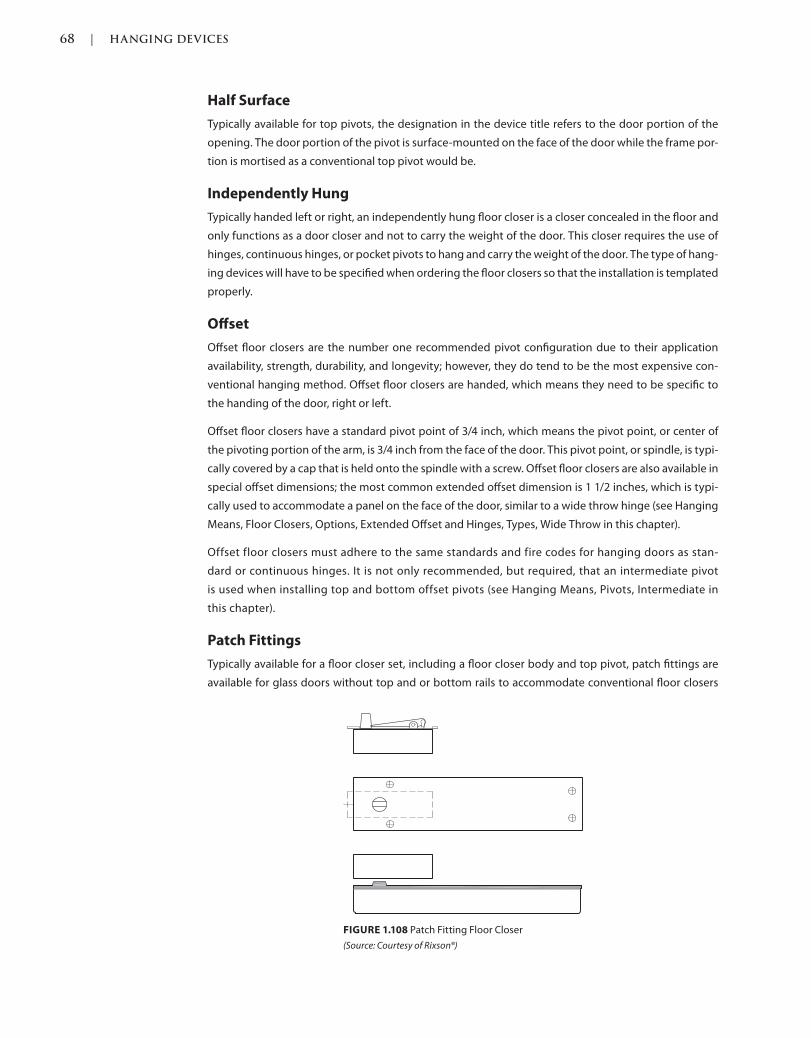
68 | HANGING DEVICES
c01.indd Page 68 03/02/2015 09:18:52:PM
Half Surface
Typically available for top pivots, the designation in the device title refers to the door portion of the
opening. The door portion of the pivot is surface-mounted on the face of the door while the frame por-
tion is mortised as a conventional top pivot would be.
Independently Hung
Typically handed left or right, an independently hung floor closer is a closer concealed in the floor and
only functions as a door closer and not to carry the weight of the door. This closer requires the use of
hinges, continuous hinges, or pocket pivots to hang and carry the weight of the door. The type of hang-
ing devices will have to be specified when ordering the floor closers so that the installation is templated
properly.
Offset
Offset floor closers are the number one recommended pivot configuration due to their application
availability, strength, durability, and longevity; however, they do tend to be the most expensive con-
ventional hanging method. Offset floor closers are handed, which means they need to be specific to
the handing of the door, right or left.
Offset floor closers have a standard pivot point of 3/4 inch, which means the pivot point, or center of
the pivoting portion of the arm, is 3/4 inch from the face of the door. This pivot point, or spindle, is typi-
cally covered by a cap that is held onto the spindle with a screw. Offset floor closers are also available in
special offset dimensions; the most common extended offset dimension is 1 1/2 inches, which is typi-
cally used to accommodate a panel on the face of the door, similar to a wide throw hinge (see Hanging
Means, Floor Closers, Options, Extended Offset and Hinges, Types, Wide Throw in this chapter).
Offset floor closers must adhere to the same standards and fire codes for hanging doors as stan-
dard or continuous hinges. It is not only recommended, but required, that an intermediate pivot
is used when installing top and bottom offset pivots (see Hanging Means, Pivots, Intermediate in
this chapter).
Patch Fittings
Typically available for a floor closer set, including a floor closer body and top pivot, patch fittings are
available for glass doors without top and or bottom rails to accommodate conventional floor closers
FIGURE 1.108 Patch Fitting Floor Closer
(Source: Courtesy of Rixson®)
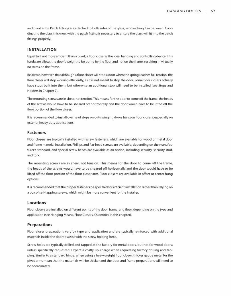
HANGING DEVICES | 69
c01.indd Page 69 03/02/2015 09:18:52:PM
and pivot arms. Patch fittings are attached to both sides of the glass, sandwiching it in between. Coor-
dinating the glass thickness with the patch fitting is necessary to ensure the glass will fit into the patch
fittings properly.
INSTALLATION
Equal to if not more efficient than a pivot, a floor closer is the ideal hanging and controlling device. This
hardware allows the door’s weight to be borne by the floor and not on the frame, resulting in virtually
no stress on the frame.
Be aware, however, that although a floor closer will stop a door when the spring reaches full tension, the
floor closer will stop working efficiently, as it is not meant to stop the door. Some floor closers actually
have stops built into them, but otherwise an additional stop will need to be installed (see Stops and
Holders in Chapter 7).
The mounting screws are in shear, not tension. This means for the door to come off the frame, the heads
of the screws would have to be sheared off horizontally and the door would have to be lifted off the
floor portion of the floor closer.
It is recommended to install overhead stops on out-swinging doors hung on floor closers, especially on
exterior heavy duty applications.
Fasteners
Floor closers are typically installed with screw fasteners, which are available for wood or metal door
and frame material installation. Phillips and flat-head screws are available, depending on the manufac-
turer’s standard, and special screw heads are available as an option, including security, security stud,
and torx.
The mounting screws are in shear, not tension. This means for the door to come off the frame,
the heads of the screws would have to be sheared off horizontally and the door would have to be
lifted off the floor portion of the floor closer arm. Floor closers are available in offset or center hung
options.
It is recommended that the proper fasteners be specified for efficient installation rather than relying on
a box of self-tapping screws, which might be more convenient for the installer.
Locations
Floor closers are installed on different points of the door, frame, and floor, depending on the type and
application (see Hanging Means, Floor Closers, Quantities in this chapter).
Preparations
Floor closer preparations vary by type and application and are typically reinforced with additional
materials inside the door to assist with the screw holding force.
Screw holes are typically drilled and tapped at the factory for metal doors, but not for wood doors,
unless specifically requested. Expect a costly up-charge when requesting factory drilling and tap-
ping. Similar to a standard hinge, when using a heavyweight floor closer, thicker gauge metal for the
pivot arms mean that the materials will be thicker and the door and frame preparations will need to
be coordinated.
70 | HANGING DEVICES
c01.indd Page 70 03/02/2015 09:18:52:PM
SLIDING AND FOLDING DOOR HARDWARE
Also Known As: Track and Hardware
DESCRIPTION
Track and hardware is used to hang folding and sliding doors, which are sometimes used for aesthetic
purposes, but typically are installed to maximize the space around the opening by not having a swing-
ing door that requires clearance all around so that the door swings freely.
Typical folding and sliding doors are not fire rated, although there are a handful of manufactur-
ers that do manufacture a fire rated heavy duty fire rated sliding door for building separation
applications.
When specifying track and hardware, you must also consider any type of pulls, locking devices, or
stops that may be required as they are typically not included in the standard track and hardware set.
PROPERTIES
Sliding door track and hanger components are manufactured with different weights, thicknesses, and
materials in order to accommodate the various door sizes, materials, and weights.
Bearings
NEEDLE BEARINGS
Some manufacturers incorporate needle bearings into the hangers in order to help with the lateral or
side-to-side movement of the hangers with the sliding operation of the door.
Finishes
Tracks have traditionally not been a consideration for aesthetic reasons and were concealed as often
as possible. In recent years, sliding doors have become more popular with unique track and hanger
designs being developed to add aesthetic appeal to the opening. Finishes include polished steel or
stainless steel, polished and satin brass or bronze, and anodized aluminum.
Materials
Tracks are typically available in anodized aluminum, brass, bronze, stainless steel, and steel, depending
on the manufacturer and availability.
Tracks
Tracks are available in different configurations, which in turn work with specific hangers, which are
the mechanisms with rollers that attach the door with brackets and allow the door to slide across
the track.
BOX SHAPE
This track is square where the top attaches to the top jamb of the framed opening or the face of a wall
and the wheels suspend the door and slide along the inside of the box. There is an opening at the bot-
tom where the hanger sticks through and attaches to the door. The track can be straight for a single
sliding door or a pair of bi-parting doors, can be manufactured curved for a curved wall and opening,
or can be installed parallel in multiples to accommodate a bi-passing application. The track also has
the option to come manufactured with a fascia, also known as flashing, to cover the track, rollers, and
hangers behind it.
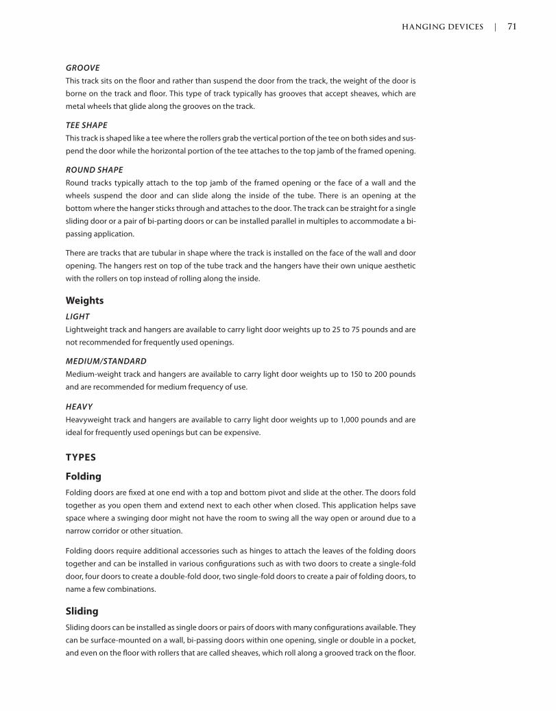
HANGING DEVICES | 71
c01.indd Page 71 03/02/2015 09:18:52:PM
GROOVE
This track sits on the floor and rather than suspend the door from the track, the weight of the door is
borne on the track and floor. This type of track typically has grooves that accept sheaves, which are
metal wheels that glide along the grooves on the track.
TEE SHAPE
This track is shaped like a tee where the rollers grab the vertical portion of the tee on both sides and sus-
pend the door while the horizontal portion of the tee attaches to the top jamb of the framed opening.
ROUND SHAPE
Round tracks typically attach to the top jamb of the framed opening or the face of a wall and the
wheels suspend the door and can slide along the inside of the tube. There is an opening at the
bottom where the hanger sticks through and attaches to the door. The track can be straight for a single
sliding door or a pair of bi-parting doors or can be installed parallel in multiples to accommodate a bi-
passing application.
There are tracks that are tubular in shape where the track is installed on the face of the wall and door
opening. The hangers rest on top of the tube track and the hangers have their own unique aesthetic
with the rollers on top instead of rolling along the inside.
Weights
LIGHT
Lightweight track and hangers are available to carry light door weights up to 25 to 75 pounds and are
not recommended for frequently used openings.
MEDIUM/STANDARD
Medium-weight track and hangers are available to carry light door weights up to 150 to 200 pounds
and are recommended for medium frequency of use.
HEAVY
Heavyweight track and hangers are available to carry light door weights up to 1,000 pounds and are
ideal for frequently used openings but can be expensive.
TYPES
Folding
Folding doors are fixed at one end with a top and bottom pivot and slide at the other. The doors fold
together as you open them and extend next to each other when closed. This application helps save
space where a swinging door might not have the room to swing all the way open or around due to a
narrow corridor or other situation.
Folding doors require additional accessories such as hinges to attach the leaves of the folding doors
together and can be installed in various configurations such as with two doors to create a single-fold
door, four doors to create a double-fold door, two single-fold doors to create a pair of folding doors, to
name a few combinations.
Sliding
Sliding doors can be installed as single doors or pairs of doors with many configurations available. They
can be surface-mounted on a wall, bi-passing doors within one opening, single or double in a pocket,
and even on the floor with rollers that are called sheaves, which roll along a grooved track on the floor.
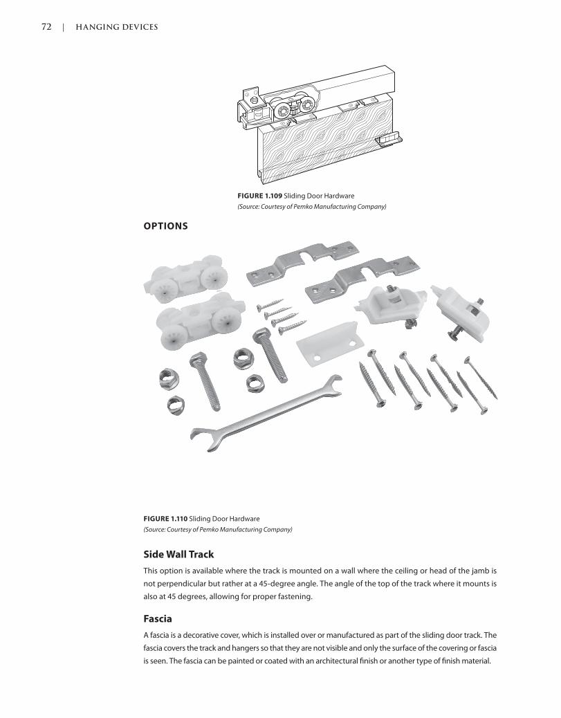
72 | HANGING DEVICES
c01.indd Page 72 03/02/2015 09:18:52:PM
OPTIONS
Side Wall Track
This option is available where the track is mounted on a wall where the ceiling or head of the jamb is
not perpendicular but rather at a 45-degree angle. The angle of the top of the track where it mounts is
also at 45 degrees, allowing for proper fastening.
Fascia
A fascia is a decorative cover, which is installed over or manufactured as part of the sliding door track. The
fascia covers the track and hangers so that they are not visible and only the surface of the covering or fascia
is seen. The fascia can be painted or coated with an architectural finish or another type of finish material.
FIGURE 1.110 Sliding Door Hardware
(Source: Courtesy of Pemko Manufacturing Company)
FIGURE 1.109 Sliding Door Hardware
(Source: Courtesy of Pemko Manufacturing Company)

HANGING DEVICES | 73
c01.indd Page 73 03/02/2015 09:18:52:PM
Guides
Floor guides are available to help guide the doors for optimal use and to help avoid any damage to the
surrounding conditions.
FIGURE 1.111 Sliding Wall Track
(Source: Courtesy of Pemko Manufacturing Company)
FIGURE 1.112 Track Fascia
(Source: Courtesy of Pemko Manufacturing Company)
FIGURE 1.113 Track Fascia
(Source: Courtesy of Pemko Manufacturing Company)
FIGURE 1.114 Channel Guide
(Source: Courtesy of Pemko Manufacturing Company)
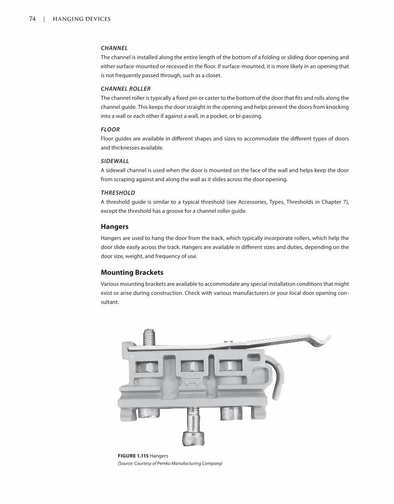
74 | HANGING DEVICES
c01.indd Page 74 03/02/2015 09:18:52:PM
CHANNEL
The channel is installed along the entire length of the bottom of a folding or sliding door opening and
either surface-mounted or recessed in the floor. If surface-mounted, it is more likely in an opening that
is not frequently passed through, such as a closet.
CHANNEL ROLLER
The channel roller is typically a fixed pin or caster to the bottom of the door that fits and rolls along the
channel guide. This keeps the door straight in the opening and helps prevent the doors from knocking
into a wall or each other if against a wall, in a pocket, or bi-passing.
FLOOR
Floor guides are available in different shapes and sizes to accommodate the different types of doors
and thicknesses available.
SIDEWALL
A sidewall channel is used when the door is mounted on the face of the wall and helps keep the door
from scraping against and along the wall as it slides across the door opening.
THRESHOLD
A threshold guide is similar to a typical threshold (see Accessories, Types, Thresholds in Chapter 7),
except the threshold has a groove for a channel roller guide.
Hangers
Hangers are used to hang the door from the track, which typically incorporate rollers, which help the
door slide easily across the track. Hangers are available in different sizes and duties, depending on the
door size, weight, and frequency of use.
Mounting Brackets
Various mounting brackets are available to accommodate any special installation conditions that might
exist or arise during construction. Check with various manufacturers or your local door opening con-
sultant.
FIGURE 1.115 Hangers
(Source: Courtesy of Pemko Manufacturing Company)
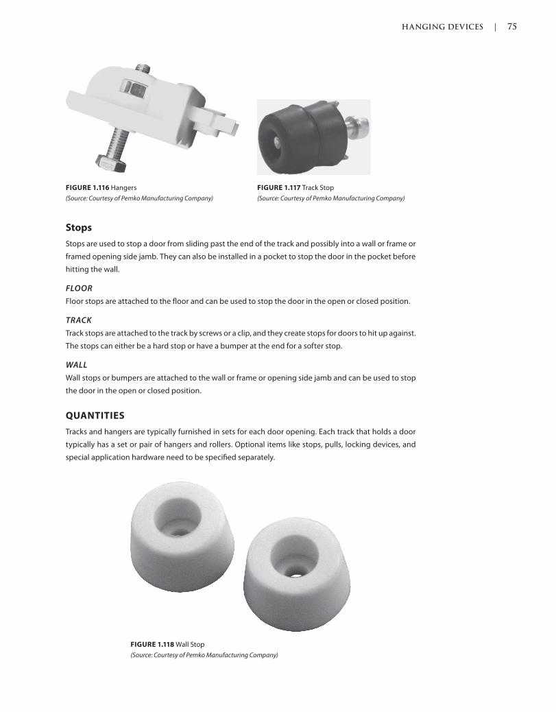
HANGING DEVICES | 75
c01.indd Page 75 03/02/2015 09:18:52:PM
Stops
Stops are used to stop a door from sliding past the end of the track and possibly into a wall or frame or
framed opening side jamb. They can also be installed in a pocket to stop the door in the pocket before
hitting the wall.
FLOOR
Floor stops are attached to the floor and can be used to stop the door in the open or closed position.
TRACK
Track stops are attached to the track by screws or a clip, and they create stops for doors to hit up against.
The stops can either be a hard stop or have a bumper at the end for a softer stop.
WALL
Wall stops or bumpers are attached to the wall or frame or opening side jamb and can be used to stop
the door in the open or closed position.
QUANTITIES
Tracks and hangers are typically furnished in sets for each door opening. Each track that holds a door
typically has a set or pair of hangers and rollers. Optional items like stops, pulls, locking devices, and
special application hardware need to be specified separately.
FIGURE 1.118 Wall Stop
(Source: Courtesy of Pemko Manufacturing Company)
FIGURE 1.116 Hangers
(Source: Courtesy of Pemko Manufacturing Company)
FIGURE 1.117 Track Stop
(Source: Courtesy of Pemko Manufacturing Company)

76 | HANGING DEVICES
c01.indd Page 76 03/02/2015 09:18:52:PM
APPLICATIONS
Bi-Folding
Bi-folding doors are two-panel doors that are fixed at one end with a top and bottom pivot and slide at
the other. The doors fold together as you open them and extend next to each other when closed. This
application helps save space where a swinging door might not have the room to swing all the way open
or around due to a narrow corridor or other situation.
Bi-folding doors require hinges to attach the leaves of the folding doors together and can be installed
in various configurations such as with two doors to create a single-fold door.
FIGURE 1.120 Face Mounted Sliding Door
(Source: Courtesy of Rockwood® Manufacturing Company)
FIGURE 1.119 Bi-Folding Door Hardware
(Source: Courtesy of Pemko Manufacturing Company)

HANGING DEVICES | 77
c01.indd Page 77 03/02/2015 09:18:52:PM
Bi-Parting
Like a pair of doors that part from each other and separate to open the door, bi-parting doors can
be surface-mounted on the wall or installed in pockets in the walls. Suspended or floor-mounted
tracks can be used for this application. Typically, the same track that is used for a single sliding
door track can be used; the doors are butted up against each other and part from one another as
they open.
Bi-Passing
Bi-passing doors are installed with two doors next to each other on separate tracks, either aligned or
on one double track. This allows the doors to pass each other, saving space since there is no need for
space to swing doors open. Bi-passing doors are typically opened one at a time, hiding behind one
another, which blocks one side of the door opening. Suspended or floor-mounted tracks can be used
for this application.
Face-Mounted
Also known as barn door hardware, sliding doors can be installed where the track is surface-mounted
to the face of a wall and the door hangs and slides on the front of an opening. When surface-mounted,
and depending on aesthetic preference, the track is either exposed or a decorative fascia is installed
to hide the track.
Pocket sliding doors conceal half of the track in a pocket in a wall, hiding the door in the wall when
in the open position. This type of door is the most space-saving type if the wall already exists,
FIGURE 1.121 Sliding Door Edge Pull
(Source: Courtesy of Rockwood® Manufacturing Company)
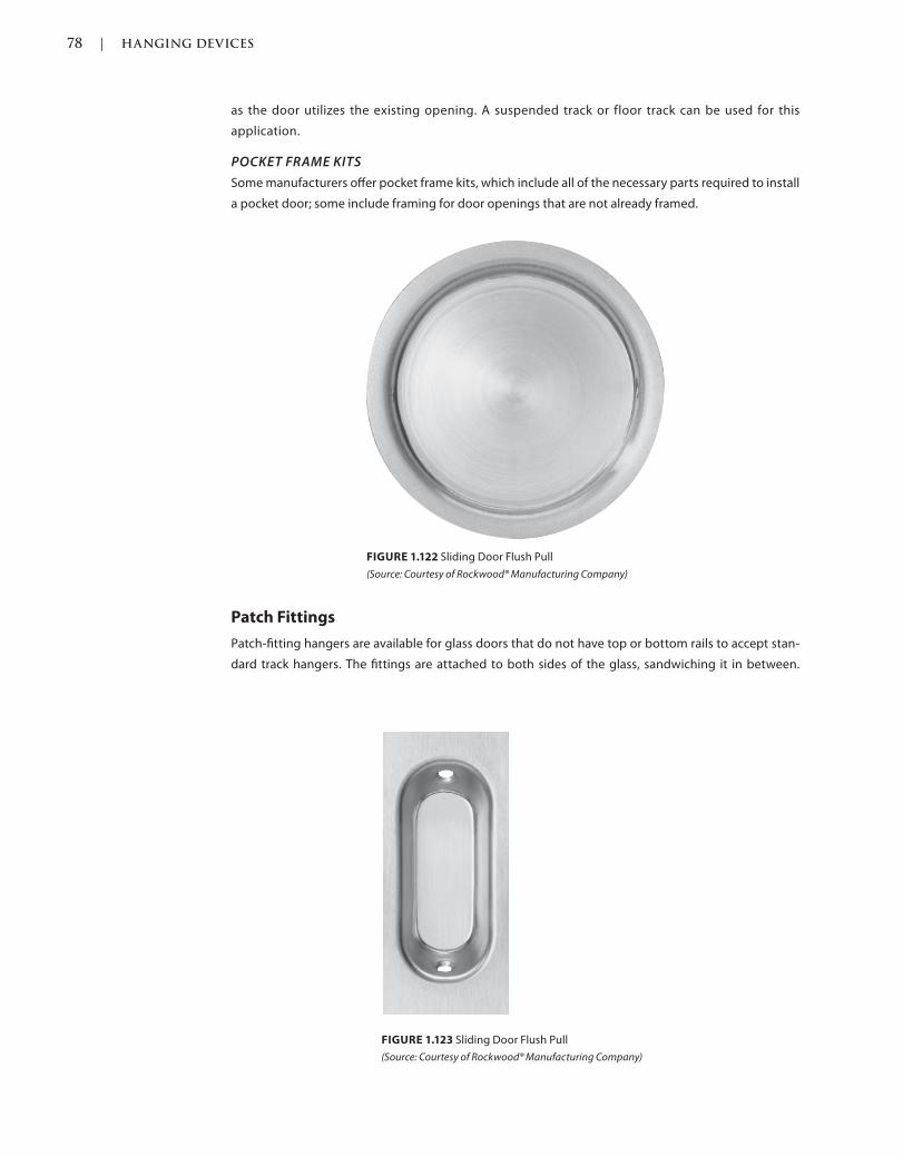
78 | HANGING DEVICES
c01.indd Page 78 03/02/2015 09:18:52:PM
as the door utilizes the existing opening. A suspended track or floor track can be used for this
application.
POCKET FRAME KITS
Some manufacturers offer pocket frame kits, which include all of the necessary parts required to install
a pocket door; some include framing for door openings that are not already framed.
Patch Fittings
Patch-fitting hangers are available for glass doors that do not have top or bottom rails to accept stan-
dard track hangers. The fittings are attached to both sides of the glass, sandwiching it in between.
FIGURE 1.123 Sliding Door Flush Pull
(Source: Courtesy of Rockwood® Manufacturing Company)
FIGURE 1.122 Sliding Door Flush Pull
(Source: Courtesy of Rockwood® Manufacturing Company)
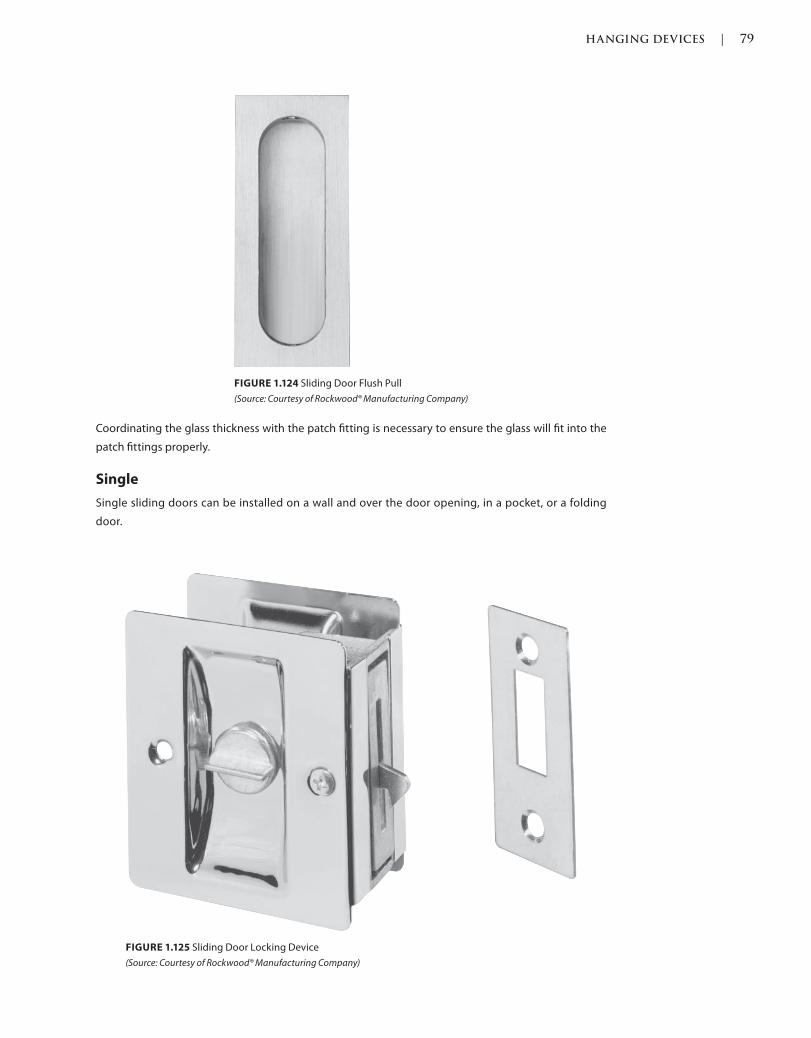
HANGING DEVICES | 79
c01.indd Page 79 03/02/2015 09:18:52:PM
Coordinating the glass thickness with the patch fitting is necessary to ensure the glass will fit into the
patch fittings properly.
Single
Single sliding doors can be installed on a wall and over the door opening, in a pocket, or a folding
door.
FIGURE 1.124 Sliding Door Flush Pull
(Source: Courtesy of Rockwood® Manufacturing Company)
FIGURE 1.125 Sliding Door Locking Device
(Source: Courtesy of Rockwood® Manufacturing Company)
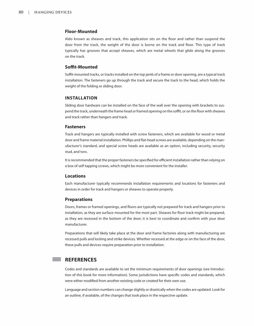
80 | HANGING DEVICES
c01.indd Page 80 03/02/2015 09:18:52:PM
Floor-Mounted
Aldo known as sheaves and track, this application sits on the floor and rather than suspend the
door from the track, the weight of the door is borne on the track and floor. This type of track
typically has grooves that accept sheaves, which are metal wheels that glide along the grooves
on the track.
Soffit-Mounted
Soffit-mounted tracks, or tracks installed on the top jamb of a frame or door opening, are a typical track
installation. The fasteners go up through the track and secure the track to the head, which holds the
weight of the folding or sliding door.
INSTALLATION
Sliding door hardware can be installed on the face of the wall over the opening with brackets to sus-
pend the track, underneath the frame head or framed opening on the soffit, or on the floor with sheaves
and track rather than hangers and track.
Fasteners
Track and hangers are typically installed with screw fasteners, which are available for wood or metal
door and frame material installation. Phillips and flat-head screws are available, depending on the man-
ufacturer’s standard, and special screw heads are available as an option, including security, security
stud, and torx.
It is recommended that the proper fasteners be specified for efficient installation rather than relying on
a box of self-tapping screws, which might be more convenient for the installer.
Locations
Each manufacturer typically recommends installation requirements and locations for fasteners and
devices in order for track and hangers or sheaves to operate properly.
Preparations
Doors, frames or framed openings, and floors are typically not prepared for track and hangers prior to
installation, as they are surface-mounted for the most part. Sheaves for floor track might be prepared,
as they are recessed in the bottom of the door; it is best to coordinate and confirm with your door
manufacturer.
Preparations that will likely take place at the door and frame factories along with manufacturing are
recessed pulls and locking and strike devices. Whether recessed at the edge or on the face of the door,
these pulls and devices require preparation prior to installation.
REFERENCES
Codes and standards are available to set the minimum requirements of door openings (see Introduc-
tion of this book for more information). Some jurisdictions have specific codes and standards, which
were either modified from another existing code or created for their own use.
Language and section numbers can change slightly or drastically when the codes are updated. Look for
an outline, if available, of the changes that took place in the respective update.
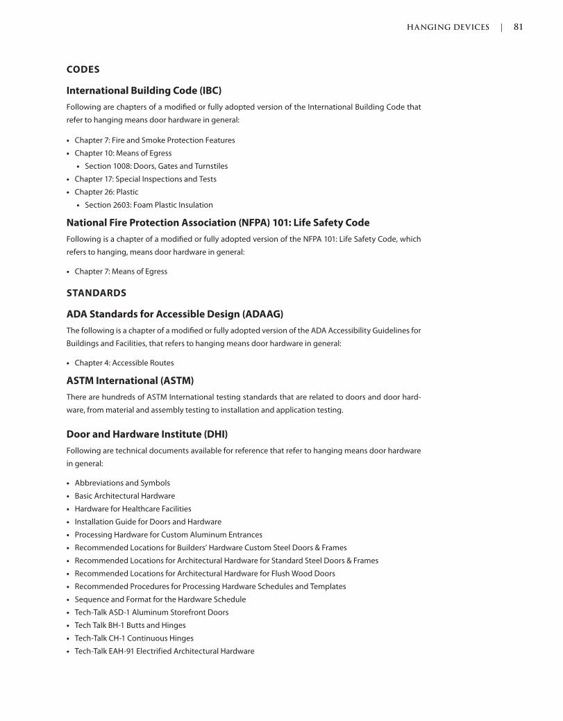
HANGING DEVICES | 81
c01.indd Page 81 03/02/2015 09:18:52:PM
CODES
International Building Code (IBC)
Following are chapters of a modified or fully adopted version of the International Building Code that
refer to hanging means door hardware in general:
Chapter 7: Fire and Smoke Protection Features
Chapter 10: Means of Egress
Section 1008: Doors, Gates and Turnstiles
Chapter 17: Special Inspections and Tests
Chapter 26: Plastic
Section 2603: Foam Plastic Insulation
National Fire Protection Association (NFPA) 101: Life Safety Code
Following is a chapter of a modified or fully adopted version of the NFPA 101: Life Safety Code, which
refers to hanging, means door hardware in general:
Chapter 7: Means of Egress
STANDARDS
ADA Standards for Accessible Design (ADAAG)
The following is a chapter of a modified or fully adopted version of the ADA Accessibility Guidelines for
Buildings and Facilities, that refers to hanging means door hardware in general:
Chapter 4: Accessible Routes
ASTM International (ASTM)
There are hundreds of ASTM International testing standards that are related to doors and door hard-
ware, from material and assembly testing to installation and application testing.
Door and Hardware Institute (DHI)
Following are technical documents available for reference that refer to hanging means door hardware
in general:
Abbreviations and Symbols
Basic Architectural Hardware
Hardware for Healthcare Facilities
Installation Guide for Doors and Hardware
Processing Hardware for Custom Aluminum Entrances
Recommended Locations for Builders’ Hardware Custom Steel Doors & Frames
Recommended Locations for Architectural Hardware for Standard Steel Doors & Frames
Recommended Locations for Architectural Hardware for Flush Wood Doors
Recommended Procedures for Processing Hardware Schedules and Templates
Sequence and Format for the Hardware Schedule
Tech-Talk ASD-1 Aluminum Storefront Doors
Tech Talk BH-1 Butts and Hinges
Tech-Talk CH-1 Continuous Hinges
Tech-Talk EAH-91 Electrified Architectural Hardware
82 | HANGING DEVICES
c01.indd Page 82 03/02/2015 09:18:52:PM
Tech-Talk FC-1 Concealed Floor Closers
Tech-Talk P-1 Pivots
Tech-Talk SP-1 Hardware Specification Writing
International Code Council (ICC) A117.1 Accessible and Usable Buildings
and Facilities
International Code Council A117.1 Accessible and Usable Buildings and
Facilities, (ICC)
The following is a chapter of a modified or fully adopted version of the ICC A117.1 Accessible and Usable
Buildings and Facilities that refers to hanging means door hardware in general:
Chapter 4: Accessible Routes
National Fire Protection Association (NFPA)
The following are chapters of a modified or fully adopted version of NFPA 80: Standard for Fire Doors
and Other Opening Protectives, that refer to hanging means door hardware in general:
Chapter 5: Care and Maintenance
Chapter 6: Swinging Doors with Builders Hardware
Chapter 7: Swinging Doors with Fire Door Hardware
Chapter 8: Horizontally Sliding Doors
Chapter 9: Special-Purpose Horizontally Sliding Accordion or Folding Doors
Chapter 16: Access Doors
Chapter 19: Installation, Testing, and Maintenance of Fire Dampers
Annex A: Explanatory Material
The following is a chapter of a modified or fully adopted version of NFPA 105: Standard for Smoke
Door Assemblies and Other Opening Protectives that refers to hanging means door hardware in
general:
Chapter 6: Installation, Testing, and Maintenance of Smoke Dampers
The following is a chapter of a modified or fully adopted version of NFPA 252: Standard Method of Fire
Tests of Door Assemblies that refers to hanging means door hardware in general:
Chapter 5: Fire Door Assembly
Annex B: Commentary
American National Standards Institute/Builders Hardware Manufacturers
Association (ANSI/BHMA)
The following are standards that refer to hanging means door hardware in general:
ANSI/BHMA A156.1 American National Standard for Butts and Hinges
ANSI/BHMA A156.7 American National Standard for Template Hinge Dimensions
ANSI/BHMA A156.14 American National Standard for Sliding and Folding Door Hardware
ANSI/BHMA A156.17 American National Standard for Self Closing Hinges & Pivots
ANSI/BHMA A156.18 American National Standard for Materials and Finishes
ANSI/BHMA A156.20 American National Standard for Strap and Tee Hinges and Hasps
ANSI/BHMA A156.26 American National Standard for Continuous Hinges

HANGING DEVICES | 83
c01.indd Page 83 03/02/2015 09:18:52:PM
ANSI/BHMA A156.32 American National Standard for Integrated Door Openings Assemblies
ANSI/BHMA A156.115 American National Standard for Hardware Preparation in Steel Doors and
Steel Frames
ANSI/BHMA A156.115W American National Standard for Hardware Preparation in Wood Doors with
Wood or Steel Frames

85
c02.indd Page 85 03/03/2015 02:12:36:PM
Now that the door is hanging, the next part of the sequence is to secure the door.
When specifying any type of electrified hardware, operations descriptions, also known as operations
narratives, should always be used. These descriptions are short paragraphs that describe the operation
of every part of the opening from either side, so that the designer, installer, and user can all have the
same understanding of what is supposed to happen at the opening at any given time. Also required
should be elevation and point-to-point diagrams. Elevations provide an overview of what the opening
looks like with all of the components of the system connected. The point-to-point shows the system
connections as well, but is geared more toward the actual wiring, including the colors and connections
of each. A logic diagram might be used by the person who designed the system in order to lay out the
“logic” of the system flow and process.
Some electrified devices are now being manufactured with solar power; that is, they get their power
either fully or partially from the sun in order to operate. This might be beneficial for a very remote site
that might require some type of electrified locking device, where it is not feasible to monitor or change
the batteries.
INACTIVE LEAF OF PAIRS OF DOORS
When specifying or scheduling a pair of doors, the inactive leaf is always secured first. Logistically, if the
inactive leaf of a pair of doors is not secured first, then the active leaf has nothing to secure itself into,
leaving both of them unsecure and vulnerable. In other words, the inactive leaf must act as the fixed
material that the frame or wall would be for a single door opening.
Once we have secured the inactive leaf of a pair, or if we are specifying a single door opening only, the
proper securing device is then specified. There are many factors, options, and preferences to take into
account when securing the opening, including function, code, aesthetics, sustainability, and personal
preference.
Securing Devices
2
86 | SECURING DEVICES
c02.indd Page 86 03/03/2015 02:12:36:PM
BOLTS
Also Known As: Flushbolts, Surface Bolts, Slide Bolts
DESCRIPTION
Bolts are used primarily to secure the inactive leaf of a pair of doors so that the active leaf has the ability
to be secured into the inactive leaf. This can be accomplished using several applications, depending on
the function of the door opening and its related codes.
Manual flushbolts are typically the most common means to secure an inactive leaf of a pair of nonfire
rated doors, and they are also known as lever extension flushbolts. Automatic flushbolts are typically
used to secure fire rated doors, and self-latching flushbolts are another available type.
Although bolts are most commonly used, exit hardware might be used instead to secure the inactive
leaf, typically when both leaves of the pair of doors are active or when life safety codes require both
doors of the pair for egress. Other ways to secure an inactive door are surface-mounted manual slide
bolts and Cremone bolts, which are decorative surface bolts typically operated by a knob or lever.
PROPERTIES
Bolts are typically manufactured as a piece of solid metal like a pin or rod, which extends out or off of
a door and into a frame, wall, or door and into a strike plate. The extension or throw of the bolt can be
done manually or automatically, and it can be mounted on the surface or face of the door or frame, or
recessed and flush within the door. Flushbolts are typically pins or rods housed in a metal casing for
installation into a recessed pocket in the edge of the door.
Corners
RADIUS
Radius corner bolts and or housings are rounded at the edges instead of having square corners and
do not affect the operation of the device, only the aesthetics. Radius corners are most typically used
on residential applications, although they are available and able to be used in commercial operations.
SQUARE CORNER
Square corner bolts and or housings are square-edged and are most typically used in the commercial
industry, although they are available and able to be used in residential applications as well.
Finishes
Depending on the manufacturer’s availability, bolts are typically available in most architectural finishes.
They are not usually available in a prime finish, which is typically used for painted applications that
would match the door and or frame; plated finishes are most commonly used. Sometimes finished
products are painted the same color and at the same time as the door, frame, and surrounding areas.
Painting the device is not recommended as it might cause the paint to dry in places where there are
moving parts, prohibiting the device from operating properly or at all.
Painting bolts or anything onsite is not recommended as it will contribute to poor air quality for those
working on and eventually working in the space. Using a manufacturer’s factory finish might even help
contribute to credits toward a current or future green building standard, code, or certification.
Grades
With strict guidelines for testing, bolts are rated in grades 1, 2, and 3 for various types of tests including
impact, friction, and cycle tests.
SECURING DEVICES | 87
c02.indd Page 87 03/03/2015 02:12:36:PM
IMPACT
Impact tests rate the impact of force against the opening in the same direction of the door swing.
The impact is typically off center on the door where the bolts are installed.
FRICTION
Friction tests measure the retraction of the bolt with a weight load to the bolt against the strike in the
direction of the door swing. Typically, the weight load will make it more difficult and, if very heavy, will
prevent the bolt from retracting at all.
CYCLE
Cycle tests measure the full extension and retraction of the bolt into and out of the strike. In other words,
the bolts are engaged and disengaged over and over again until they meet ANSI/BHMA minimum
requirements or fail to work properly.
Materials
Bolts are manufactured from various materials, including aluminum, brass, bronze, stainless steel, or
steel. The material type specified and installed can depend on the door opening application and fire
rating requirements.
If a door opening is fire rated, the material tested and approved is likely steel, since it can withstand the
high temperatures of a fire for a certain period of time. If anything other than a steel base is installed
on a fire rated door opening and a fire occurs, the metal might melt enough to cause the opening to
fail, allowing the fire to spread from one side of the opening to the other prematurely of the actual fire
rating of the door.
Automatic bolts and flushbolts are manufactured specifically to the door material, whether wood or
metal. Typically, bolts for metal doors are mortised into a cutout in the edge of the door several inches
down from the top corner of the door. Because wood doors are typically weaker when mortised for
door hardware, bolts for wood doors are typically mortised into the edge of the door at the top corner
and wrap around the top of the door for a more secure installation.
Ratings
NONFIRE RATED
Nonfire rated bolts can only be used on doors that are not fire rated openings and would typically be of
the manual type, as they are not able to latch automatically at the time of a fire.
FIRE RATED
Fire rated bolts should only be applied to fire rated doors, although they can be used on nonfire rated
as well for function. Fire rated bolts are typically of the automatic type, so they can latch automatically
at the time of a fire to protect the nonfire side of the opening from the fire side.
Sizes
Bolts are available in different lengths, depending on the door height and reach necessary to operate
the bolt.
AUTOMATIC FLUSHBOLTS
Typically a small bolt at the very top and bottom edges of the door, these devices operate automatically
and do not need to be reached or accessed to operate. Therefore, the top is typically out of reach
without help from a stool or ladder.
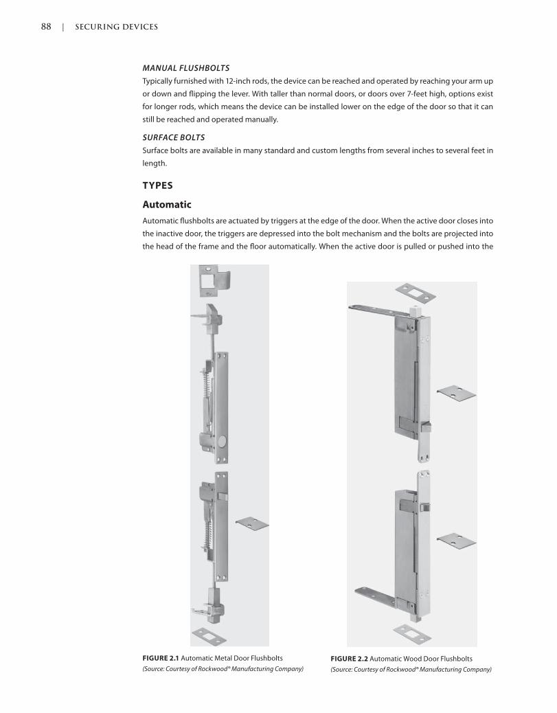
88 | SECURING DEVICES
c02.indd Page 88 03/03/2015 02:12:36:PM
MANUAL FLUSHBOLTS
Typically furnished with 12-inch rods, the device can be reached and operated by reaching your arm up
or down and flipping the lever. With taller than normal doors, or doors over 7-feet high, options exist
for longer rods, which means the device can be installed lower on the edge of the door so that it can
still be reached and operated manually.
SURFACE BOLTS
Surface bolts are available in many standard and custom lengths from several inches to several feet in
length.
TYPES
Automatic
Automatic flushbolts are actuated by triggers at the edge of the door. When the active door closes into
the inactive door, the triggers are depressed into the bolt mechanism and the bolts are projected into
the head of the frame and the floor automatically. When the active door is pulled or pushed into the
FIGURE 2.1 Automatic Metal Door Flushbolts
(Source: Courtesy of Rockwood® Manufacturing Company)
FIGURE 2.2 Automatic Wood Door Flushbolts
(Source: Courtesy of Rockwood® Manufacturing Company)
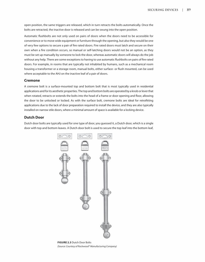
SECURING DEVICES | 89
c02.indd Page 89 03/03/2015 02:12:36:PM
open position, the same triggers are released, which in turn retracts the bolts automatically. Once the
bolts are retracted, the inactive door is released and can be swung into the open position.
Automatic flushbolts are not only used on pairs of doors when the doors need to be accessible for
convenience or to move wide equipment or furniture through the opening, but also they would be one
of very few options to secure a pair of fire rated doors. Fire rated doors must latch and secure on their
own when a fire condition occurs, so manual or self-latching doors would not be an option, as they
must be set up manually by someone to lock the door, whereas automatic doors will always do the job
without any help. There are some exceptions to having to use automatic flushbolts on pairs of fire rated
doors. For example, in rooms that are typically not inhabited by humans, such as a mechanical room
housing a transformer or a storage room, manual bolts, either surface- or flush mounted, can be used
where acceptable to the AHJ on the inactive leaf of a pair of doors.
Cremone
A cremone bolt is a surface-mounted top and bottom bolt that is most typically used in residential
applications and for its aesthetic properties. The top and bottom bolts are operated by a knob or lever that
when rotated, retracts or extends the bolts into the head of a frame or door opening and floor, allowing
the door to be unlocked or locked. As with the surface bolt, cremone bolts are ideal for retrofitting
applications due to the lack of door preparation required to install the device, and they are also typically
installed on narrow stile doors, where a minimal amount of space is available for a locking device.
Dutch Door
Dutch door bolts are typically used for one type of door, you guessed it, a Dutch door, which is a single
door with top and bottom leaves. A Dutch door bolt is used to secure the top leaf into the bottom leaf,
FIGURE 2.3 Dutch Door Bolts
(Source: Courtesy of Rockwood® Manufacturing Company)
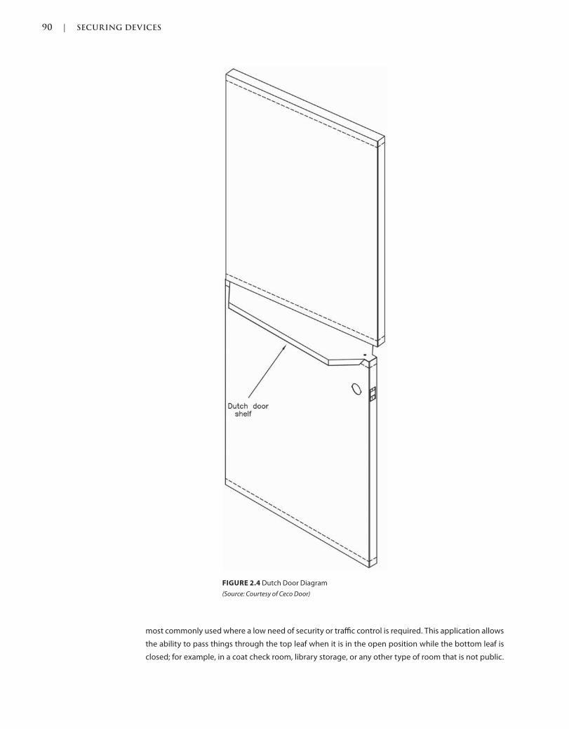
90 | SECURING DEVICES
c02.indd Page 90 03/03/2015 02:12:36:PM
most commonly used where a low need of security or traffic control is required. This application allows
the ability to pass things through the top leaf when it is in the open position while the bottom leaf is
closed; for example, in a coat check room, library storage, or any other type of room that is not public.
FIGURE 2.4 Dutch Door Diagram
(Source: Courtesy of Ceco Door)
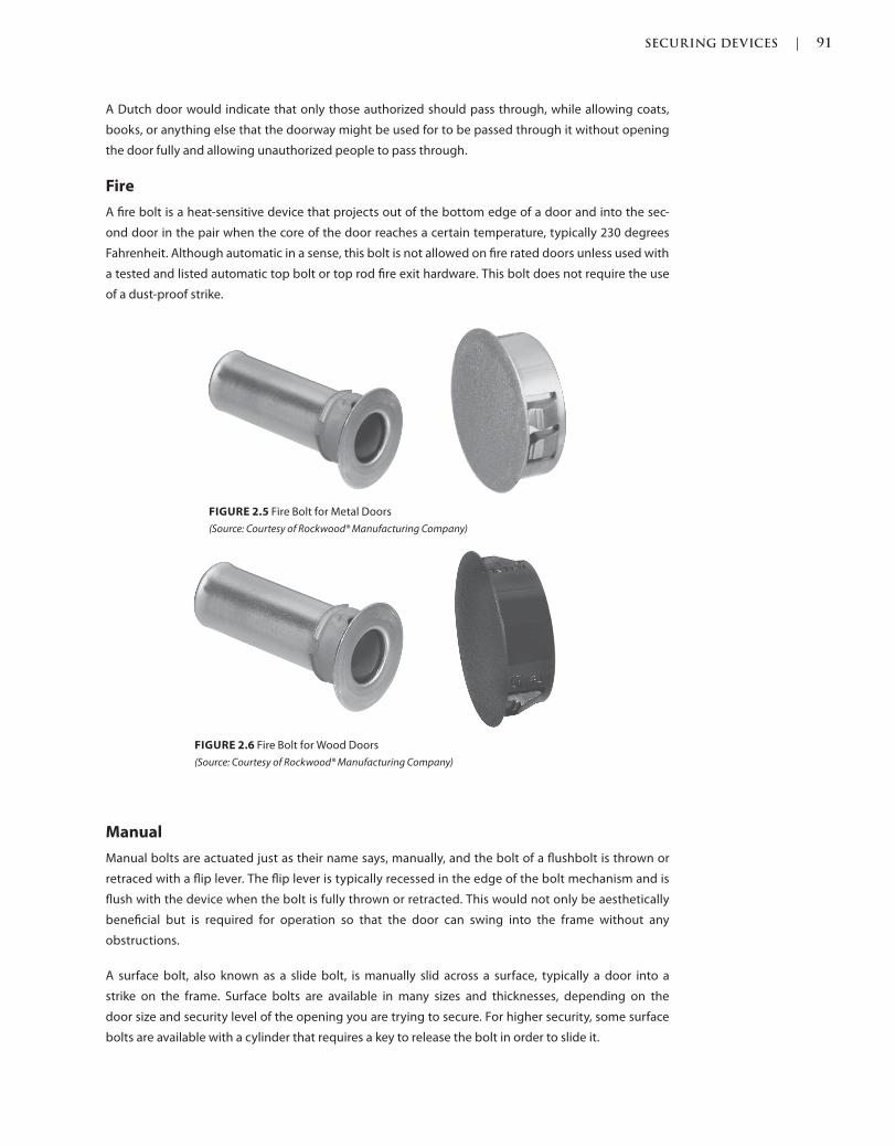
SECURING DEVICES | 91
c02.indd Page 91 03/03/2015 02:12:36:PM
A Dutch door would indicate that only those authorized should pass through, while allowing coats,
books, or anything else that the doorway might be used for to be passed through it without opening
the door fully and allowing unauthorized people to pass through.
Fire
A fire bolt is a heat-sensitive device that projects out of the bottom edge of a door and into the sec-
ond door in the pair when the core of the door reaches a certain temperature, typically 230 degrees
Fahrenheit. Although automatic in a sense, this bolt is not allowed on fire rated doors unless used with
a tested and listed automatic top bolt or top rod fire exit hardware. This bolt does not require the use
of a dust-proof strike.
Manual
Manual bolts are actuated just as their name says, manually, and the bolt of a flushbolt is thrown or
retraced with a flip lever. The flip lever is typically recessed in the edge of the bolt mechanism and is
flush with the device when the bolt is fully thrown or retracted. This would not only be aesthetically
beneficial but is required for operation so that the door can swing into the frame without any
obstructions.
A surface bolt, also known as a slide bolt, is manually slid across a surface, typically a door into a
strike on the frame. Surface bolts are available in many sizes and thicknesses, depending on the
door size and security level of the opening you are trying to secure. For higher security, some surface
bolts are available with a cylinder that requires a key to release the bolt in order to slide it.
FIGURE 2.6 Fire Bolt for Wood Doors
(Source: Courtesy of Rockwood® Manufacturing Company)
FIGURE 2.5 Fire Bolt for Metal Doors
(Source: Courtesy of Rockwood® Manufacturing Company)
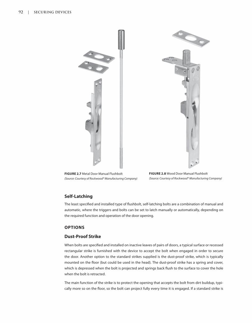
92 | SECURING DEVICES
c02.indd Page 92 03/03/2015 02:12:36:PM
Self-Latching
The least specified and installed type of flushbolt, self-latching bolts are a combination of manual and
automatic, where the triggers and bolts can be set to latch manually or automatically, depending on
the required function and operation of the door opening.
OPTIONS
Dust-Proof Strike
When bolts are specified and installed on inactive leaves of pairs of doors, a typical surface or recessed
rectangular strike is furnished with the device to accept the bolt when engaged in order to secure
the door. Another option to the standard strikes supplied is the dust-proof strike, which is typically
mounted on the floor (but could be used in the head). The dust-proof strike has a spring and cover,
which is depressed when the bolt is projected and springs back flush to the surface to cover the hole
when the bolt is retracted.
The main function of the strike is to protect the opening that accepts the bolt from dirt buildup, typi-
cally more so on the floor, so the bolt can project fully every time it is engaged. If a standard strike is
FIGURE 2.7 Metal Door Manual Flushbolt
(Source: Courtesy of Rockwood® Manufacturing Company)
FIGURE 2.8 Wood Door Manual Flushbolt
(Source: Courtesy of Rockwood® Manufacturing Company)
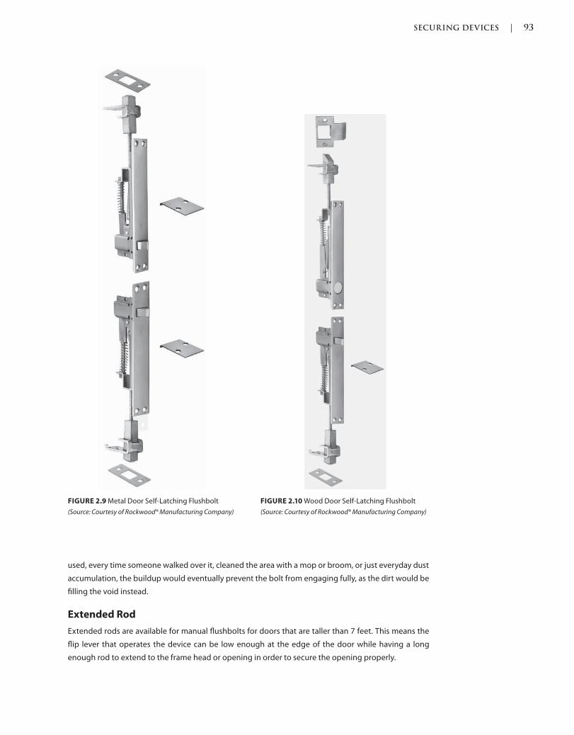
SECURING DEVICES | 93
c02.indd Page 93 03/03/2015 02:12:36:PM
used, every time someone walked over it, cleaned the area with a mop or broom, or just everyday dust
accumulation, the buildup would eventually prevent the bolt from engaging fully, as the dirt would be
filling the void instead.
Extended Rod
Extended rods are available for manual flushbolts for doors that are taller than 7 feet. This means the
flip lever that operates the device can be low enough at the edge of the door while having a long
enough rod to extend to the frame head or opening in order to secure the opening properly.
FIGURE 2.9 Metal Door Self-Latching Flushbolt
(Source: Courtesy of Rockwood® Manufacturing Company)
FIGURE 2.10 Wood Door Self-Latching Flushbolt
(Source: Courtesy of Rockwood® Manufacturing Company)
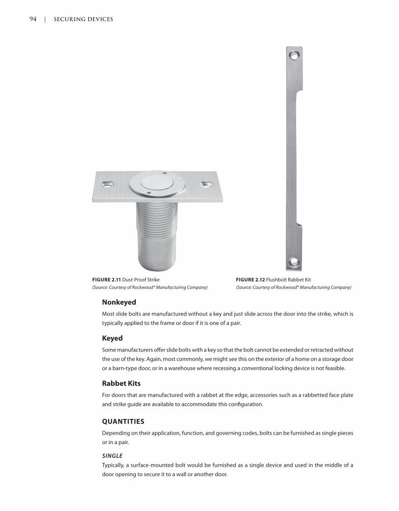
94 | SECURING DEVICES
c02.indd Page 94 03/03/2015 02:12:36:PM
Nonkeyed
Most slide bolts are manufactured without a key and just slide across the door into the strike, which is
typically applied to the frame or door if it is one of a pair.
Keyed
Some manufacturers offer slide bolts with a key so that the bolt cannot be extended or retracted without
the use of the key. Again, most commonly, we might see this on the exterior of a home on a storage door
or a barn-type door, or in a warehouse where recessing a conventional locking device is not feasible.
Rabbet Kits
For doors that are manufactured with a rabbet at the edge, accessories such as a rabbetted face plate
and strike guide are available to accommodate this configuration.
QUANTITIES
Depending on their application, function, and governing codes, bolts can be furnished as single pieces
or in a pair.
SINGLE
Typically, a surface-mounted bolt would be furnished as a single device and used in the middle of a
door opening to secure it to a wall or another door.
FIGURE 2.11 Dust-Proof Strike
(Source: Courtesy of Rockwood® Manufacturing Company)
FIGURE 2.12 Flushbolt Rabbet Kit
(Source: Courtesy of Rockwood® Manufacturing Company)
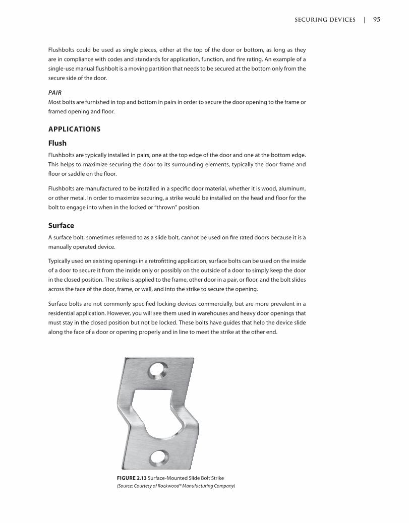
SECURING DEVICES | 95
c02.indd Page 95 03/03/2015 02:12:36:PM
Flushbolts could be used as single pieces, either at the top of the door or bottom, as long as they
are in compliance with codes and standards for application, function, and fire rating. An example of a
single-use manual flushbolt is a moving partition that needs to be secured at the bottom only from the
secure side of the door.
PAIR
Most bolts are furnished in top and bottom in pairs in order to secure the door opening to the frame or
framed opening and floor.
APPLICATIONS
Flush
Flushbolts are typically installed in pairs, one at the top edge of the door and one at the bottom edge.
This helps to maximize securing the door to its surrounding elements, typically the door frame and
floor or saddle on the floor.
Flushbolts are manufactured to be installed in a specific door material, whether it is wood, aluminum,
or other metal. In order to maximize securing, a strike would be installed on the head and floor for the
bolt to engage into when in the locked or “thrown” position.
Surface
A surface bolt, sometimes referred to as a slide bolt, cannot be used on fire rated doors because it is a
manually operated device.
Typically used on existing openings in a retrofitting application, surface bolts can be used on the inside
of a door to secure it from the inside only or possibly on the outside of a door to simply keep the door
in the closed position. The strike is applied to the frame, other door in a pair, or floor, and the bolt slides
across the face of the door, frame, or wall, and into the strike to secure the opening.
Surface bolts are not commonly specified locking devices commercially, but are more prevalent in a
residential application. However, you will see them used in warehouses and heavy door openings that
must stay in the closed position but not be locked. These bolts have guides that help the device slide
along the face of a door or opening properly and in line to meet the strike at the other end.
FIGURE 2.13 Surface-Mounted Slide Bolt Strike
(Source: Courtesy of Rockwood® Manufacturing Company)
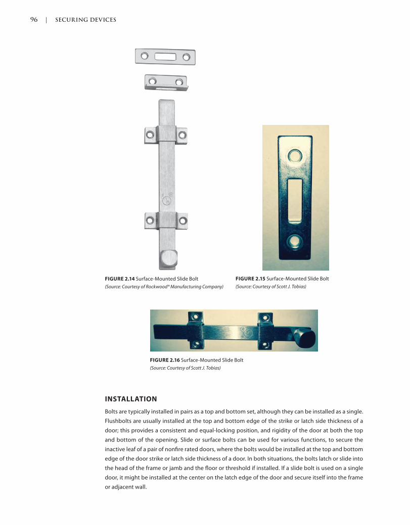
96 | SECURING DEVICES
c02.indd Page 96 03/03/2015 02:12:36:PM
INSTALLATION
Bolts are typically installed in pairs as a top and bottom set, although they can be installed as a single.
Flushbolts are usually installed at the top and bottom edge of the strike or latch side thickness of a
door; this provides a consistent and equal-locking position, and rigidity of the door at both the top
and bottom of the opening. Slide or surface bolts can be used for various functions, to secure the
inactive leaf of a pair of nonfire rated doors, where the bolts would be installed at the top and bottom
edge of the door strike or latch side thickness of a door. In both situations, the bolts latch or slide into
the head of the frame or jamb and the floor or threshold if installed. If a slide bolt is used on a single
door, it might be installed at the center on the latch edge of the door and secure itself into the frame
or adjacent wall.
FIGURE 2.14 Surface-Mounted Slide Bolt
(Source: Courtesy of Rockwood® Manufacturing Company)
FIGURE 2.15 Surface-Mounted Slide Bolt
(Source: Courtesy of Scott J. Tobias)
FIGURE 2.16 Surface-Mounted Slide Bolt
(Source: Courtesy of Scott J. Tobias)
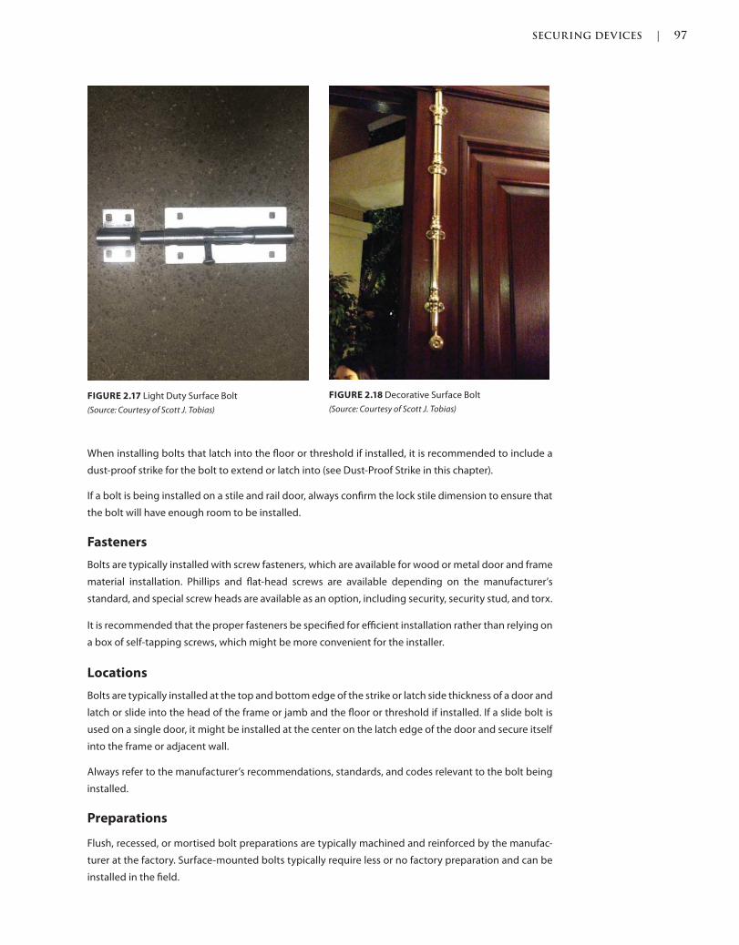
SECURING DEVICES | 97
c02.indd Page 97 03/03/2015 02:12:36:PM
When installing bolts that latch into the floor or threshold if installed, it is recommended to include a
dust-proof strike for the bolt to extend or latch into (see Dust-Proof Strike in this chapter).
If a bolt is being installed on a stile and rail door, always confirm the lock stile dimension to ensure that
the bolt will have enough room to be installed.
Fasteners
Bolts are typically installed with screw fasteners, which are available for wood or metal door and frame
material installation. Phillips and flat-head screws are available depending on the manufacturer’s
standard, and special screw heads are available as an option, including security, security stud, and torx.
It is recommended that the proper fasteners be specified for efficient installation rather than relying on
a box of self-tapping screws, which might be more convenient for the installer.
Locations
Bolts are typically installed at the top and bottom edge of the strike or latch side thickness of a door and
latch or slide into the head of the frame or jamb and the floor or threshold if installed. If a slide bolt is
used on a single door, it might be installed at the center on the latch edge of the door and secure itself
into the frame or adjacent wall.
Always refer to the manufacturer’s recommendations, standards, and codes relevant to the bolt being
installed.
Preparations
Flush, recessed, or mortised bolt preparations are typically machined and reinforced by the manufac-
turer at the factory. Surface-mounted bolts typically require less or no factory preparation and can be
installed in the field.
FIGURE 2.17 Light Duty Surface Bolt
(Source: Courtesy of Scott J. Tobias)
FIGURE 2.18 Decorative Surface Bolt
(Source: Courtesy of Scott J. Tobias)
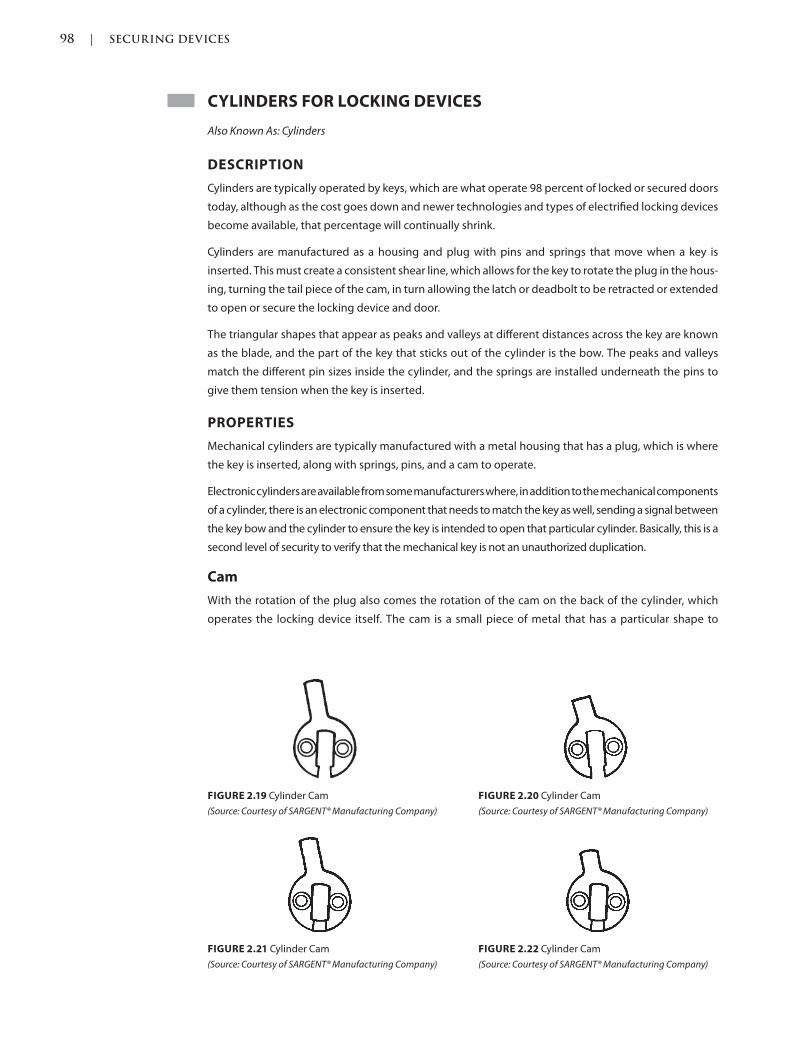
98 | SECURING DEVICES
c02.indd Page 98 03/03/2015 02:12:36:PM
CYLINDERS FOR LOCKING DEVICES
Also Known As: Cylinders
DESCRIPTION
Cylinders are typically operated by keys, which are what operate 98 percent of locked or secured doors
today, although as the cost goes down and newer technologies and types of electrified locking devices
become available, that percentage will continually shrink.
Cylinders are manufactured as a housing and plug with pins and springs that move when a key is
inserted. This must create a consistent shear line, which allows for the key to rotate the plug in the hous-
ing, turning the tail piece of the cam, in turn allowing the latch or deadbolt to be retracted or extended
to open or secure the locking device and door.
The triangular shapes that appear as peaks and valleys at different distances across the key are known
as the blade, and the part of the key that sticks out of the cylinder is the bow. The peaks and valleys
match the different pin sizes inside the cylinder, and the springs are installed underneath the pins to
give them tension when the key is inserted.
PROPERTIES
Mechanical cylinders are typically manufactured with a metal housing that has a plug, which is where
the key is inserted, along with springs, pins, and a cam to operate.
Electronic cylinders are available from some manufacturers where, in addition to the mechanical components
of a cylinder, there is an electronic component that needs to match the key as well, sending a signal between
the key bow and the cylinder to ensure the key is intended to open that particular cylinder. Basically, this is a
second level of security to verify that the mechanical key is not an unauthorized duplication.
Cam
With the rotation of the plug also comes the rotation of the cam on the back of the cylinder, which
operates the locking device itself. The cam is a small piece of metal that has a particular shape to
FIGURE 2.19 Cylinder Cam
(Source: Courtesy of SARGENT® Manufacturing Company)
FIGURE 2.20 Cylinder Cam
(Source: Courtesy of SARGENT® Manufacturing Company)
FIGURE 2.21 Cylinder Cam
(Source: Courtesy of SARGENT® Manufacturing Company)
FIGURE 2.22 Cylinder Cam
(Source: Courtesy of SARGENT® Manufacturing Company)
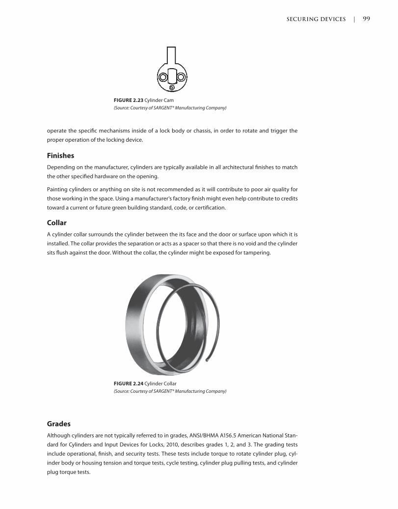
SECURING DEVICES | 99
c02.indd Page 99 03/03/2015 02:12:36:PM
operate the specific mechanisms inside of a lock body or chassis, in order to rotate and trigger the
proper operation of the locking device.
Finishes
Depending on the manufacturer, cylinders are typically available in all architectural finishes to match
the other specified hardware on the opening.
Painting cylinders or anything on site is not recommended as it will contribute to poor air quality for
those working in the space. Using a manufacturer’s factory finish might even help contribute to credits
toward a current or future green building standard, code, or certification.
Collar
A cylinder collar surrounds the cylinder between the its face and the door or surface upon which it is
installed. The collar provides the separation or acts as a spacer so that there is no void and the cylinder
sits flush against the door. Without the collar, the cylinder might be exposed for tampering.
FIGURE 2.23 Cylinder Cam
(Source: Courtesy of SARGENT® Manufacturing Company)
FIGURE 2.24 Cylinder Collar
(Source: Courtesy of SARGENT® Manufacturing Company)
Grades
Although cylinders are not typically referred to in grades, ANSI/BHMA A156.5 American National Stan-
dard for Cylinders and Input Devices for Locks, 2010, describes grades 1, 2, and 3. The grading tests
include operational, finish, and security tests. These tests include torque to rotate cylinder plug, cyl-
inder body or housing tension and torque tests, cycle testing, cylinder plug pulling tests, and cylinder
plug torque tests.
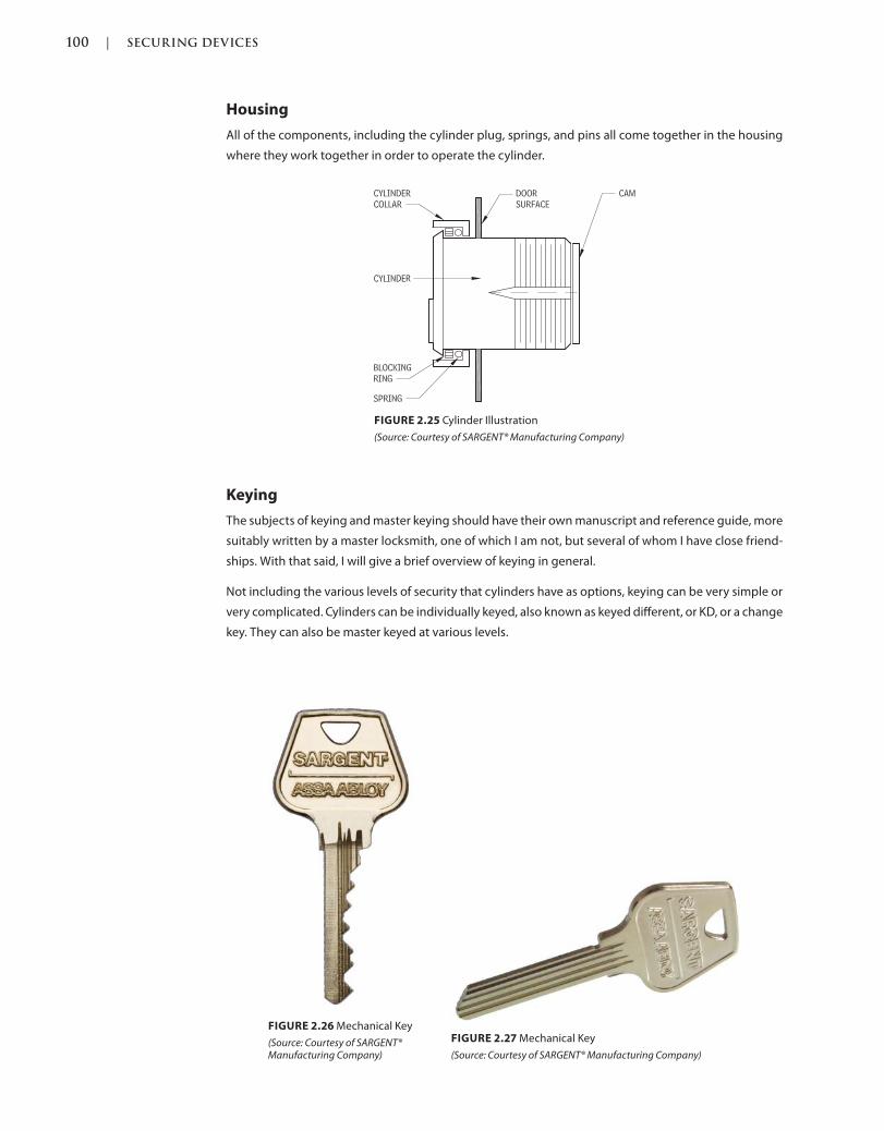
100 | SECURING DEVICES
c02.indd Page 100 03/03/2015 02:12:36:PM
Housing
All of the components, including the cylinder plug, springs, and pins all come together in the housing
where they work together in order to operate the cylinder.
Keying
The subjects of keying and master keying should have their own manuscript and reference guide, more
suitably written by a master locksmith, one of which I am not, but several of whom I have close friend-
ships. With that said, I will give a brief overview of keying in general.
Not including the various levels of security that cylinders have as options, keying can be very simple or
very complicated. Cylinders can be individually keyed, also known as keyed different, or KD, or a change
key. They can also be master keyed at various levels.
FIGURE 2.25 Cylinder Illustration
(Source: Courtesy of SARGENT® Manufacturing Company)
FIGURE 2.26 Mechanical Key
(Source: Courtesy of SARGENT® Manufacturing Company)
FIGURE 2.27 Mechanical Key
(Source: Courtesy of SARGENT® Manufacturing Company)
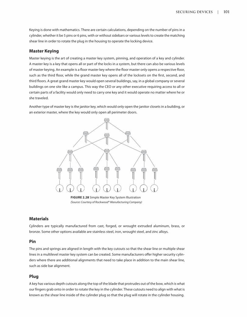
SECURING DEVICES | 101
c02.indd Page 101 03/03/2015 02:12:36:PM
Keying is done with mathematics. There are certain calculations, depending on the number of pins in a
cylinder, whether it be 5 pins or 6 pins, with or without sidebars or various levels to create the matching
shear line in order to rotate the plug in the housing to operate the locking device.
Master Keying
Master keying is the art of creating a master key system, pinning, and operation of a key and cylinder.
A master key is a key that opens all or part of the locks in a system, but there can also be various levels
of master keying. An example is a floor master key where the floor master only opens a respective floor,
such as the third floor, while the grand master key opens all of the locksets on the first, second, and
third floors. A great grand master key would open several buildings, say, in a global company or several
buildings on one site like a campus. This way the CEO or any other executive requiring access to all or
certain parts of a facility would only need to carry one key and it would operate no matter where he or
she traveled.
Another type of master key is the janitor key, which would only open the janitor closets in a building, or
an exterior master, where the key would only open all perimeter doors.
Materials
Cylinders are typically manufactured from cast, forged, or wrought extruded aluminum, brass, or
bronze. Some other options available are stainless steel, iron, wrought steel, and zinc alloys.
Pin
The pins and springs are aligned in length with the key cutouts so that the shear line or multiple shear
lines in a multilevel master key system can be created. Some manufacturers offer higher security cylin-
ders where there are additional alignments that need to take place in addition to the main shear line,
such as side bar alignment.
Plug
A key has various depth cutouts along the top of the blade that protrudes out of the bow, which is what
our fingers grab onto in order to rotate the key in the cylinder. These cutouts need to align with what is
known as the shear line inside of the cylinder plug so that the plug will rotate in the cylinder housing.
FIGURE 2.28 Simple Master Key System Illustration
(Source: Courtesy of Rockwood® Manufacturing Company)

102 | SECURING DEVICES
c02.indd Page 102 03/03/2015 02:12:36:PM
Side Bar
Some manufacturers offer higher-security cylinders, where there are additional alignments that need
to take place in addition to the main shear line, such as side bar alignment. The cylinders are manufac-
tured with bars along the sides that require the key to have grooves to accept those side bars; otherwise
the key will not enter the cylinder plug at all.
Spring
The springs and pins are aligned in length with the key cutouts so that the shear line or multiple shear
lines in a multilevel master key system can be created.
TYPES
Conventional
Conventional cylinders are available for all applications. The face of the cylinder, or housing, is round
with a round center, or plug, where the key is inserted. As described above, the shear line must be cre-
ated in order to rotate the key. A conventional cylinder can only be installed and replaced by taking
apart the locking device, which can be time consuming and costly in labor.
Electronic
Electronic cylinders are the current and next-generation technology for locking and unlocking devices.
Similar in design to mechanical cylinders, electronic cylinders require the use of power to verify the
electronic credentials of the key, in addition to the mechanical blade.
Some electronic cylinders have the ability to keep an audit trail of the opening of the cylinder, so
that it is known which key opened what door at what time of the day or night, giving another layer of
key control.
FIGURE 2.29 Electronic Cylinder and Key
(Source: Courtesy of copyright © Medeco Security Locks)
European
European cylinders are uniquely shaped cylinders manufactured for locksets made in Europe. They
have a round plug area similar to a conventional cylinder, with an elongated top portion where the pins
and springs are, rather than a round housing all around.
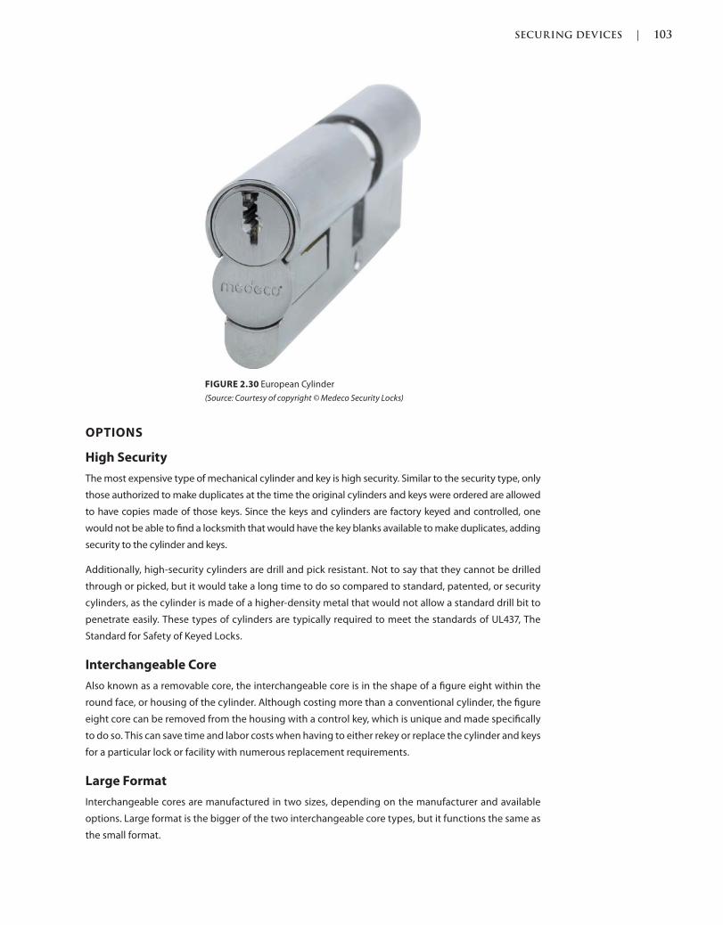
SECURING DEVICES | 103
c02.indd Page 103 03/03/2015 02:12:36:PM
OPTIONS
High Security
The most expensive type of mechanical cylinder and key is high security. Similar to the security type, only
those authorized to make duplicates at the time the original cylinders and keys were ordered are allowed
to have copies made of those keys. Since the keys and cylinders are factory keyed and controlled, one
would not be able to find a locksmith that would have the key blanks available to make duplicates, adding
security to the cylinder and keys.
Additionally, high-security cylinders are drill and pick resistant. Not to say that they cannot be drilled
through or picked, but it would take a long time to do so compared to standard, patented, or security
cylinders, as the cylinder is made of a higher-density metal that would not allow a standard drill bit to
penetrate easily. These types of cylinders are typically required to meet the standards of UL437, The
Standard for Safety of Keyed Locks.
Interchangeable Core
Also known as a removable core, the interchangeable core is in the shape of a figure eight within the
round face, or housing of the cylinder. Although costing more than a conventional cylinder, the figure
eight core can be removed from the housing with a control key, which is unique and made specifically
to do so. This can save time and labor costs when having to either rekey or replace the cylinder and keys
for a particular lock or facility with numerous replacement requirements.
Large Format
Interchangeable cores are manufactured in two sizes, depending on the manufacturer and available
options. Large format is the bigger of the two interchangeable core types, but it functions the same as
the small format.
FIGURE 2.30 European Cylinder
(Source: Courtesy of copyright © Medeco Security Locks)
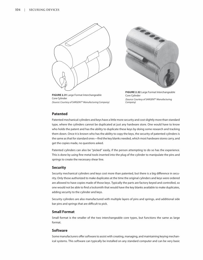
104 | SECURING DEVICES
c02.indd Page 104 03/03/2015 02:12:36:PM
Patented
Patented mechanical cylinders and keys have a little more security and cost slightly more than standard
type, where the cylinders cannot be duplicated at just any hardware store. One would have to know
who holds the patent and has the ability to duplicate these keys by doing some research and tracking
them down. Once it is known who has the ability to copy the keys, the security of patented cylinders is
the same as that for standard ones—find the key blanks needed, which most hardware stores carry, and
get the copies made, no questions asked.
Patented cylinders can also be “picked” easily, if the person attempting to do so has the experience.
This is done by using fine metal tools inserted into the plug of the cylinder to manipulate the pins and
springs to create the necessary shear line.
Security
Security mechanical cylinders and keys cost more than patented, but there is a big difference in secu-
rity. Only those authorized to make duplicates at the time the original cylinders and keys were ordered
are allowed to have copies made of those keys. Typically the parts are factory keyed and controlled, so
one would not be able to find a locksmith that would have the key blanks available to make duplicates,
adding security to the cylinder and keys.
Security cylinders are also manufactured with multiple layers of pins and springs, and additional side
bar pins and springs that are difficult to pick.
Small Format
Small format is the smaller of the two interchangeable core types, but functions the same as large
format.
Software
Some manufacturers offer software to assist with creating, managing, and maintaining keying mechan-
ical systems. This software can typically be installed on any standard computer and can be very basic
FIGURE 2.31 Large Format Interchangeable
Core Cylinder
(Source: Courtesy of SARGENT® Manufacturing Company)
FIGURE 2.32 Large Format Interchangeable
Core Cylinder
(Source: Courtesy of SARGENT® Manufacturing Company)
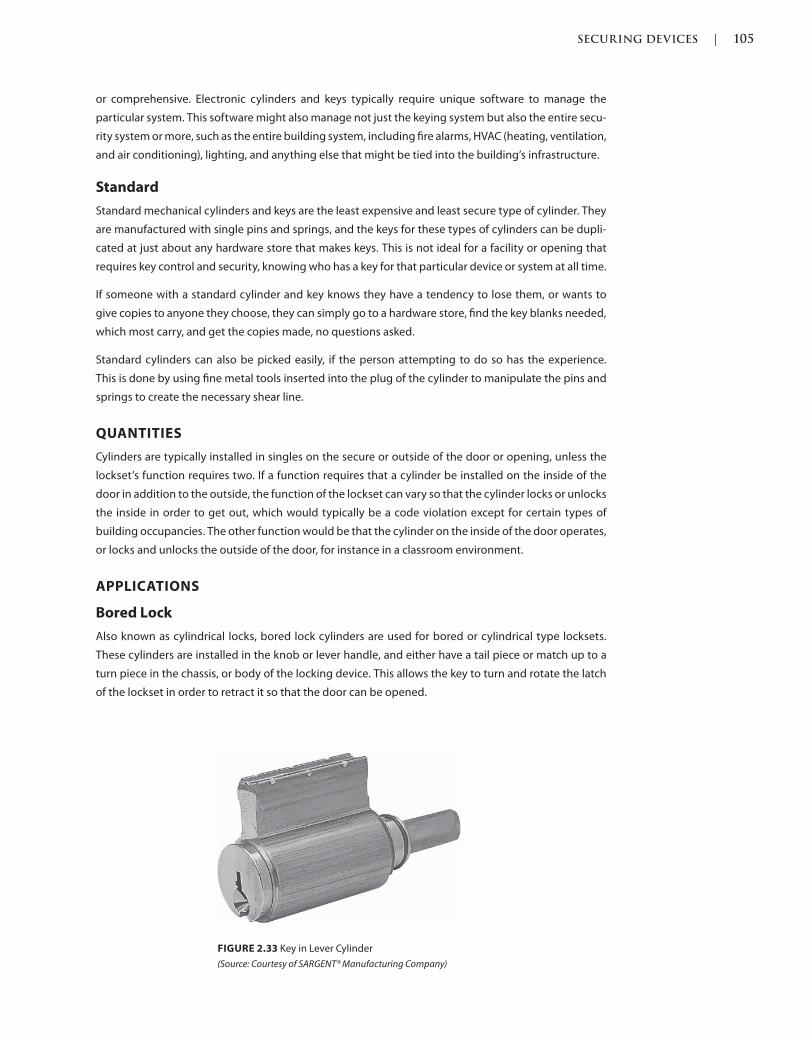
SECURING DEVICES | 105
c02.indd Page 105 03/03/2015 02:12:36:PM
or comprehensive. Electronic cylinders and keys typically require unique software to manage the
particular system. This software might also manage not just the keying system but also the entire secu-
rity system or more, such as the entire building system, including fire alarms, HVAC (heating, ventilation,
and air conditioning), lighting, and anything else that might be tied into the building’s infrastructure.
Standard
Standard mechanical cylinders and keys are the least expensive and least secure type of cylinder. They
are manufactured with single pins and springs, and the keys for these types of cylinders can be dupli-
cated at just about any hardware store that makes keys. This is not ideal for a facility or opening that
requires key control and security, knowing who has a key for that particular device or system at all time.
If someone with a standard cylinder and key knows they have a tendency to lose them, or wants to
give copies to anyone they choose, they can simply go to a hardware store, find the key blanks needed,
which most carry, and get the copies made, no questions asked.
Standard cylinders can also be picked easily, if the person attempting to do so has the experience.
This is done by using fine metal tools inserted into the plug of the cylinder to manipulate the pins and
springs to create the necessary shear line.
QUANTITIES
Cylinders are typically installed in singles on the secure or outside of the door or opening, unless the
lockset’s function requires two. If a function requires that a cylinder be installed on the inside of the
door in addition to the outside, the function of the lockset can vary so that the cylinder locks or unlocks
the inside in order to get out, which would typically be a code violation except for certain types of
building occupancies. The other function would be that the cylinder on the inside of the door operates,
or locks and unlocks the outside of the door, for instance in a classroom environment.
APPLICATIONS
Bored Lock
Also known as cylindrical locks, bored lock cylinders are used for bored or cylindrical type locksets.
These cylinders are installed in the knob or lever handle, and either have a tail piece or match up to a
turn piece in the chassis, or body of the locking device. This allows the key to turn and rotate the latch
of the lockset in order to retract it so that the door can be opened.
FIGURE 2.33 Key in Lever Cylinder
(Source: Courtesy of SARGENT® Manufacturing Company)
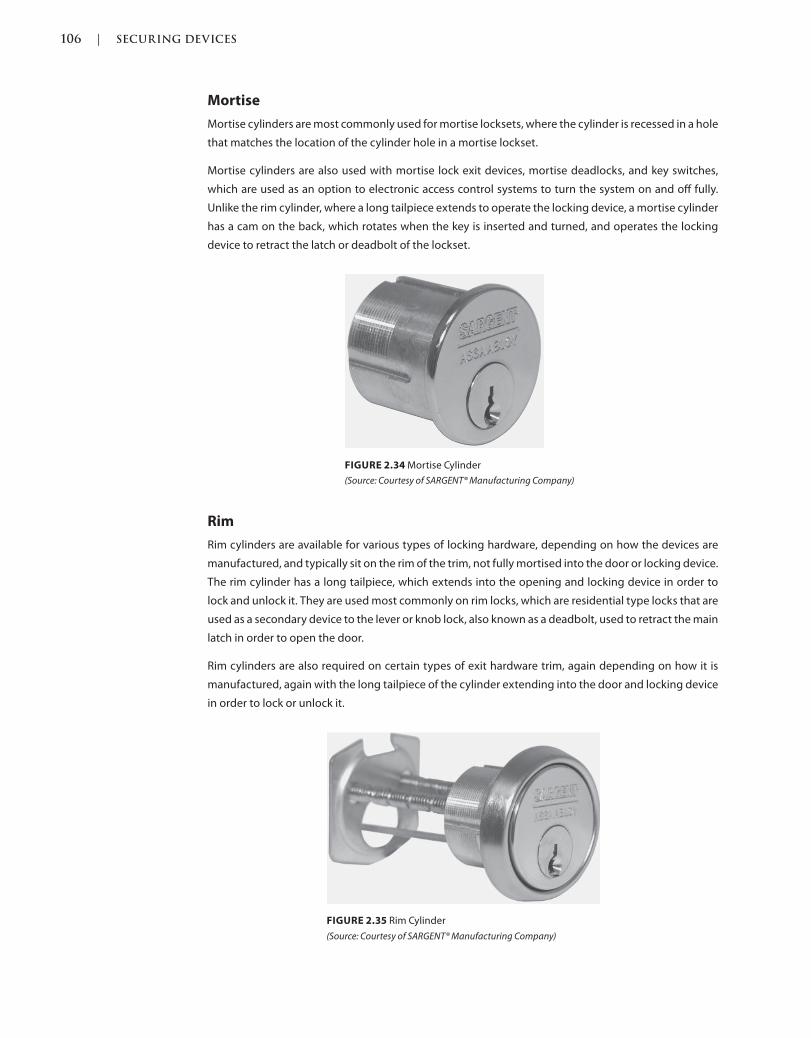
106 | SECURING DEVICES
c02.indd Page 106 03/03/2015 02:12:36:PM
Mortise
Mortise cylinders are most commonly used for mortise locksets, where the cylinder is recessed in a hole
that matches the location of the cylinder hole in a mortise lockset.
Mortise cylinders are also used with mortise lock exit devices, mortise deadlocks, and key switches,
which are used as an option to electronic access control systems to turn the system on and off fully.
Unlike the rim cylinder, where a long tailpiece extends to operate the locking device, a mortise cylinder
has a cam on the back, which rotates when the key is inserted and turned, and operates the locking
device to retract the latch or deadbolt of the lockset.
FIGURE 2.34 Mortise Cylinder
(Source: Courtesy of SARGENT® Manufacturing Company)
FIGURE 2.35 Rim Cylinder
(Source: Courtesy of SARGENT® Manufacturing Company)
Rim
Rim cylinders are available for various types of locking hardware, depending on how the devices are
manufactured, and typically sit on the rim of the trim, not fully mortised into the door or locking device.
The rim cylinder has a long tailpiece, which extends into the opening and locking device in order to
lock and unlock it. They are used most commonly on rim locks, which are residential type locks that are
used as a secondary device to the lever or knob lock, also known as a deadbolt, used to retract the main
latch in order to open the door.
Rim cylinders are also required on certain types of exit hardware trim, again depending on how it is
manufactured, again with the long tailpiece of the cylinder extending into the door and locking device
in order to lock or unlock it.
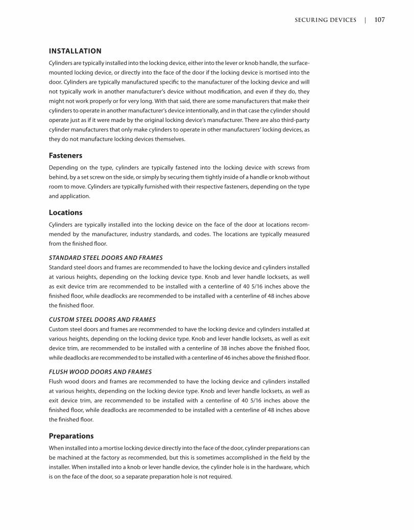
SECURING DEVICES | 107
c02.indd Page 107 03/03/2015 02:12:36:PM
INSTALLATION
Cylinders are typically installed into the locking device, either into the lever or knob handle, the surface-
mounted locking device, or directly into the face of the door if the locking device is mortised into the
door. Cylinders are typically manufactured specific to the manufacturer of the locking device and will
not typically work in another manufacturer’s device without modification, and even if they do, they
might not work properly or for very long. With that said, there are some manufacturers that make their
cylinders to operate in another manufacturer’s device intentionally, and in that case the cylinder should
operate just as if it were made by the original locking device’s manufacturer. There are also third-party
cylinder manufacturers that only make cylinders to operate in other manufacturers’ locking devices, as
they do not manufacture locking devices themselves.
Fasteners
Depending on the type, cylinders are typically fastened into the locking device with screws from
behind, by a set screw on the side, or simply by securing them tightly inside of a handle or knob without
room to move. Cylinders are typically furnished with their respective fasteners, depending on the type
and application.
Locations
Cylinders are typically installed into the locking device on the face of the door at locations recom-
mended by the manufacturer, industry standards, and codes. The locations are typically measured
from the finished floor.
STANDARD STEEL DOORS AND FRAMES
Standard steel doors and frames are recommended to have the locking device and cylinders installed
at various heights, depending on the locking device type. Knob and lever handle locksets, as well
as exit device trim are recommended to be installed with a centerline of 40 5/16 inches above the
finished floor, while deadlocks are recommended to be installed with a centerline of 48 inches above
the finished floor.
CUSTOM STEEL DOORS AND FRAMES
Custom steel doors and frames are recommended to have the locking device and cylinders installed at
various heights, depending on the locking device type. Knob and lever handle locksets, as well as exit
device trim, are recommended to be installed with a centerline of 38 inches above the finished floor,
while deadlocks are recommended to be installed with a centerline of 46 inches above the finished floor.
FLUSH WOOD DOORS AND FRAMES
Flush wood doors and frames are recommended to have the locking device and cylinders installed
at various heights, depending on the locking device type. Knob and lever handle locksets, as well as
exit device trim, are recommended to be installed with a centerline of 40 5/16 inches above the
finished floor, while deadlocks are recommended to be installed with a centerline of 48 inches above
the finished floor.
Preparations
When installed into a mortise locking device directly into the face of the door, cylinder preparations can
be machined at the factory as recommended, but this is sometimes accomplished in the field by the
installer. When installed into a knob or lever handle device, the cylinder hole is in the hardware, which
is on the face of the door, so a separate preparation hole is not required.
108 | SECURING DEVICES
c02.indd Page 108 03/03/2015 02:12:36:PM
DOOR POSITION SWITCHES
Also Known As: Door Contacts, DPS, Door Status Switch, Magnetic Contact
DESCRIPTION
Although it could be as simple as a single device trigger depressed by a door when it closes into a frame,
the typical door position switch is a magnetic device that is wired to an alarm and/or computer system.
A typical application would signal when the door is in the open position and not properly in the frame.
The newest in electromechanical locking devices is to have a door position switch built into the locking
device itself. With that said, the door position switch signal does not necessarily mean that the door
is latched, locked, and secure, but there are other devices that can assist with that including a latch
position switch and electromechanical locking devices. The signal can be sent one or more ways,
including as a local alarm at the door, a remote alarm at one’s computer, or a text message to a cell
phone.
PROPERTIES
Door position switches are typically manufactured from metal, plastic, and wire components and are
usually to be housed in a plastic body.
Finishes
Door position switches can typically be found with white, gray, tan, brown, and black plastic finishes.
Heavy-duty door position switches are typically manufactured with a metal housing and finish.
Grades
Door position switches are not referred to in grades and the quality is described by operation and the
UL tests that they pass in order to comply with standards for operation.
Materials
Door position switches are typically manufactured with a plastic body or housing with metal and
wire components inside. Heavy-duty door position switches are typically manufactured with a metal
housing in lieu of plastic with a heavy-duty metal casing surrounding the wires.
Shapes
Both surface-mounted and concealed type door contacts are available from various manufacturers in
a rectangular shape, while concealed ones are also available in a round shape.
TYPES
Magnetic
The magnetic door position switch is installed with two parts as a set with the primary intent to moni-
tor and signal the state of the opening. One of the two parts of the switch is installed on the door and
one on the frame, which line up and make contact when the door is in the closed position in the frame.
Trigger
The trigger door position switch is typically installed with one part on the frame. When the door swings
closed and rests against the trigger, which can be a roller ball for example, that would indicate that the
door is in the closed position in the frame.
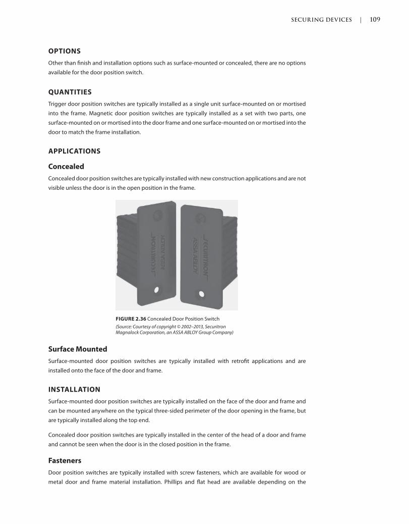
SECURING DEVICES | 109
c02.indd Page 109 03/03/2015 02:12:36:PM
OPTIONS
Other than finish and installation options such as surface-mounted or concealed, there are no options
available for the door position switch.
QUANTITIES
Trigger door position switches are typically installed as a single unit surface-mounted on or mortised
into the frame. Magnetic door position switches are typically installed as a set with two parts, one
surface-mounted on or mortised into the door frame and one surface-mounted on or mortised into the
door to match the frame installation.
APPLICATIONS
Concealed
Concealed door position switches are typically installed with new construction applications and are not
visible unless the door is in the open position in the frame.
Surface Mounted
Surface-mounted door position switches are typically installed with retrofit applications and are
installed onto the face of the door and frame.
INSTALLATION
Surface-mounted door position switches are typically installed on the face of the door and frame and
can be mounted anywhere on the typical three-sided perimeter of the door opening in the frame, but
are typically installed along the top end.
Concealed door position switches are typically installed in the center of the head of a door and frame
and cannot be seen when the door is in the closed position in the frame.
Fasteners
Door position switches are typically installed with screw fasteners, which are available for wood or
metal door and frame material installation. Phillips and flat head are available depending on the
FIGURE 2.36 Concealed Door Position Switch
(Source: Courtesy of copyright © 2002–2013, Securitron Magnalock Corporation, an ASSA ABLOY Group Company)
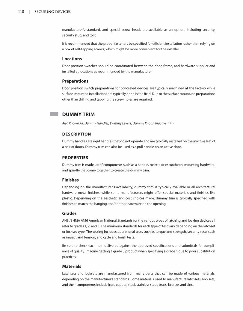
110 | SECURING DEVICES
c02.indd Page 110 03/03/2015 02:12:36:PM
manufacturer’s standard, and special screw heads are available as an option, including security,
security stud, and torx.
It is recommended that the proper fasteners be specified for efficient installation rather than relying on
a box of self-tapping screws, which might be more convenient for the installer.
Locations
Door position switches should be coordinated between the door, frame, and hardware supplier and
installed at locations as recommended by the manufacturer.
Preparations
Door position switch preparations for concealed devices are typically machined at the factory while
surface-mounted installations are typically done in the field. Due to the surface mount, no preparations
other than drilling and tapping the screw holes are required.
DUMMY TRIM
Also Known As: Dummy Handles, Dummy Levers, Dummy Knobs, Inactive Trim
DESCRIPTION
Dummy handles are rigid handles that do not operate and are typically installed on the inactive leaf of
a pair of doors. Dummy trim can also be used as a pull handle on an active door.
PROPERTIES
Dummy trim is made up of components such as a handle, rosette or escutcheon, mounting hardware,
and spindle that come together to create the dummy trim.
Finishes
Depending on the manufacturer’s availability, dummy trim is typically available in all architectural
hardware metal finishes, while some manufacturers might offer special materials and finishes like
plastic. Depending on the aesthetic and cost choices made, dummy trim is typically specified with
finishes to match the hanging and/or other hardware on the opening.
Grades
ANSI/BHMA A156 American National Standards for the various types of latching and locking devices all
refer to grades 1, 2, and 3. The minimum standards for each type of test vary depending on the latchset
or lockset type. The testing includes operational tests such as torque and strength, security tests such
as impact and tension, and cycle and finish tests.
Be sure to check each item delivered against the approved specifications and submittals for compli-
ance of quality. Imagine getting a grade 3 product when specifying a grade 1 due to poor substitution
practices.
Materials
Latchsets and locksets are manufactured from many parts that can be made of various materials,
depending on the manufacturer’s standards. Some materials used to manufacture latchsets, locksets,
and their components include iron, copper, steel, stainless steel, brass, bronze, and zinc.

SECURING DEVICES | 111
c02.indd Page 111 03/03/2015 02:12:36:PM
Sustainability
Dummy trim can possibly help contribute to sustainability with its pre- and postconsumer recycled content,
contributing to the overall material in the building. Using a factory finish and or not painting or coating
the dummy trim on site can also help contribute to obtaining credits toward building a green structure.
TYPES
Bored
Also known as cylindrical, single-bored dummy trim is typically not bored into the door but is installed
onto a mounting plate that is attached to the face of the door. With that said, there are some manu-
facturers that require additional cutouts for reinforcement and pair dummy trim might connect with
a back-to-back installation through the door. Bored dummy trim has a limited choice of lever designs;
there are typically three or four from which to choose.
Gate
A gate lock or latch is a small surface-mounted rim lockset or latchset that is typically used to keep a
door opening in a gate from swinging freely.
Mortise
Mortise dummy trim is typically not mortised into the door but is installed onto a mounting plate that
is attached to the face of the door. With that said, there are some manufacturers that require additional
cutouts for reinforcement and pair dummy trim might connect with a back-to-back installation through
the door. Mortise dummy trim comes in many choices of lever designs, typically the same choices as the
locking devices from the same series.
Tubular
Tubular dummy trim is typically not bored into the door but is installed onto a mounting plate that is
attached to the face of the door. There are some manufacturers, however, that require additional cut-
outs for reinforcement and pair dummy trim might connect with a back-to-back installation through
the door. Tubular dummy trim has a varied number of choices of lever designs—anywhere from just a
few to several dozen depending on the manufacturer.
OPTIONS
Single
Dummy trim is available in single quantities for one side of the door installation. They are typically
surface-mounted or can be reinforced inside of the door, depending on the door and hardware manu-
facturer’s recommendations.
Double
Dummy trim is available in double or pair quantities for both sides of the door installation. Depending
on the manufacturer and type, they can be surface-mounted or mounted back to back, where they are
connected to each other through the door, but still do not rotate or operate any other device or mechanism.
Decorative
Trim can also be an aesthetic component of the panic or fire exit hardware outside trim. Some
manufacturers offer many lever handle design choices for all hardware types; some have suites that

112 | SECURING DEVICES
c02.indd Page 112 03/03/2015 02:12:36:PM
allow consistent design on all hardware types, including panic and fire exit hardware. Other matching
lever types include mortise locksets, electronic access control locksets, and tubular passage, privacy,
and dummy trim. There are also suites of hardware available that include lever handles for locksets,
pull handles for glass and sliding doors, drawer pulls, door stops, coat hooks, and hinges. With coor-
dination, this would give the entire opening, interior, and building a consistent door opening design.
Escutcheon
An escutcheon is a backplate to the trim and, if one is used, it is a cylinder on the outside and thumb-
turn on the inside of the door. Escutcheons can be rectangular, oval, or custom in shape and be installed
flush, with a pattern or with framed edges.
Heavy Duty
Heavy-duty dummy trim is available for very frequently used door openings that might need to with-
stand high abuse. This trim is typically very strong and will outlast conventional-duty trim.
Knob
Knob trim is available for the outside operation of panic and fire exit hardware. Knobs are typically
round, although some custom knobs might be more oval or square. In 1992, lever handles became the
new standard, as knobs no longer met the requirements of or complied with ADA.
Lever
Lever trim is available for dummy trim hardware. Typically elongated and horizontal across the door
face at the door lock edge, lever handles have many designs and choices in aesthetic. Some manufac-
turers offer lever trim designs for their dummy trim, consistent with panic and fire exit hardware, and
locking device offerings such as mortise locksets or electronic access control locking hardware.
FIGURE 2.37 Escutcheon Options
(Source: Courtesy of SARGENT® Manufacturing Company)
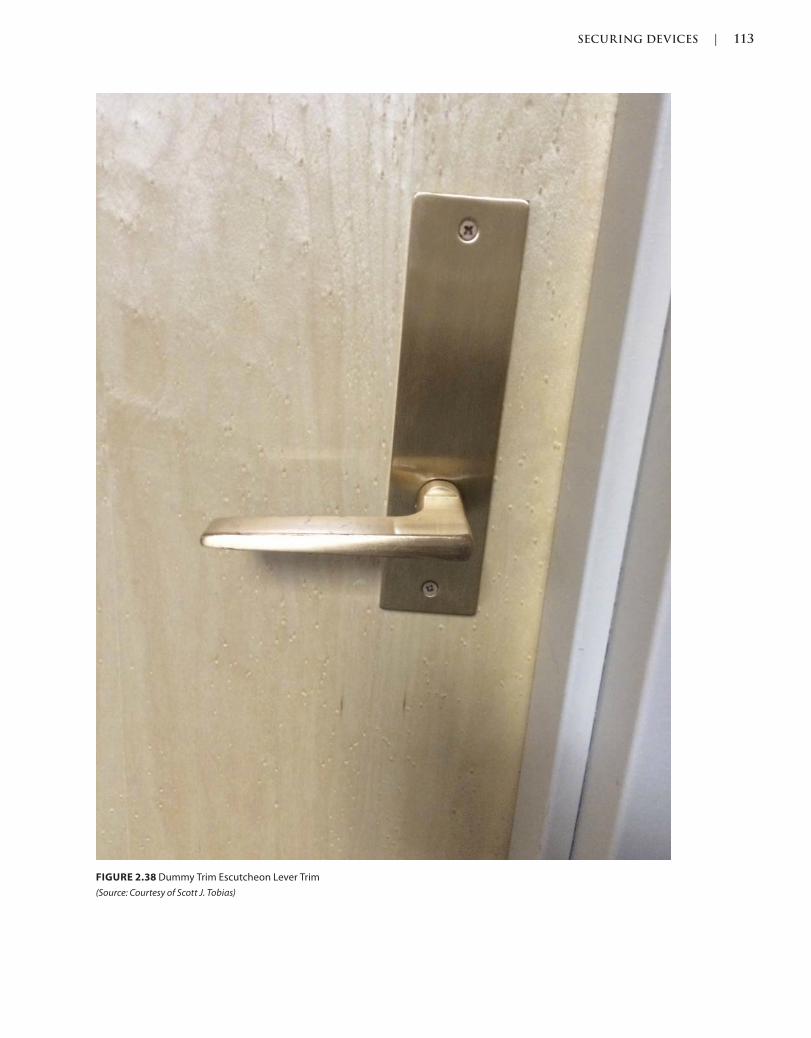
SECURING DEVICES | 113
c02.indd Page 113 03/03/2015 02:12:36:PM
FIGURE 2.38 Dummy Trim Escutcheon Lever Trim
(Source: Courtesy of Scott J. Tobias)
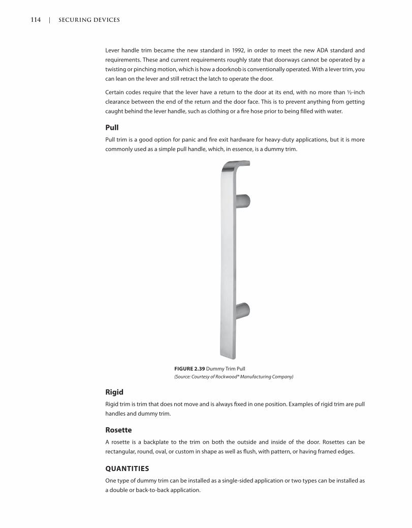
114 | SECURING DEVICES
c02.indd Page 114 03/03/2015 02:12:36:PM
Lever handle trim became the new standard in 1992, in order to meet the new ADA standard and
requirements. These and current requirements roughly state that doorways cannot be operated by a
twisting or pinching motion, which is how a doorknob is conventionally operated. With a lever trim, you
can lean on the lever and still retract the latch to operate the door.
Certain codes require that the lever have a return to the door at its end, with no more than ½-inch
clearance between the end of the return and the door face. This is to prevent anything from getting
caught behind the lever handle, such as clothing or a fire hose prior to being filled with water.
Pull
Pull trim is a good option for panic and fire exit hardware for heavy-duty applications, but it is more
commonly used as a simple pull handle, which, in essence, is a dummy trim.
Rigid
Rigid trim is trim that does not move and is always fixed in one position. Examples of rigid trim are pull
handles and dummy trim.
Rosette
A rosette is a backplate to the trim on both the outside and inside of the door. Rosettes can be
rectangular, round, oval, or custom in shape as well as flush, with pattern, or having framed edges.
QUANTITIES
One type of dummy trim can be installed as a single-sided application or two types can be installed as
a double or back-to-back application.
FIGURE 2.39 Dummy Trim Pull
(Source: Courtesy of Rockwood® Manufacturing Company)
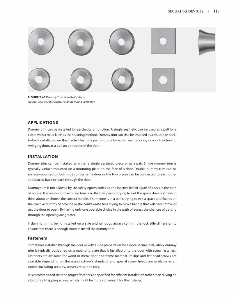
SECURING DEVICES | 115
c02.indd Page 115 03/03/2015 02:12:36:PM
APPLICATIONS
Dummy trim can be installed for aesthetics or function. A single aesthetic can be used as a pull for a
closet with a roller latch as the securing method. Dummy trim can also be installed as a double or back-
to-back installation on the inactive leaf of a pair of doors for either aesthetics or, as on a functioning
swinging door, as a pull on both sides of the door.
INSTALLATION
Dummy trim can be installed as either a single aesthetic piece or as a pair. Single dummy trim is
typically surface-mounted on a mounting plate on the face of a door. Double dummy trim can be
surface-mounted on both sides of the same door or the two pieces can be connected to each other
and placed back-to-back through the door.
Dummy trim is not allowed by life safety egress codes on the inactive leaf of a pair of doors in the path
of egress. The reason for having no trim is so that the person trying to exit the space does not have to
think about or choose the correct handle. If someone is in a panic trying to exit a space and fixates on
the inactive dummy handle, he or she could waste time trying to turn a handle that will never move or
get the door to open. By having only one operable choice in the path of egress the chances of getting
through the opening are greater.
If dummy trim is being installed on a stile and rail door, always confirm the lock stile dimension to
ensure that there is enough room to install the dummy trim.
Fasteners
Sometimes installed through the door or with a side preparation for a more secure installation, dummy
trim is typically positioned on a mounting plate that is installed onto the door with screw fasteners.
Fasteners are available for wood or metal door and frame material. Phillips and flat-head screws are
available depending on the manufacturer’s standard, and special screw heads are available as an
option, including security, security stud, and torx.
It is recommended that the proper fasteners be specified for efficient installation rather than relying on
a box of self-tapping screws, which might be more convenient for the installer.
FIGURE 2.40 Dummy Trim Rosette Options
(Source: Courtesy of SARGENT® Manufacturing Company)
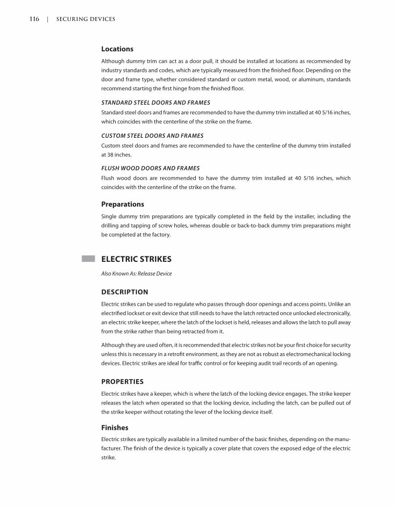
116 | SECURING DEVICES
c02.indd Page 116 03/03/2015 02:12:36:PM
Locations
Although dummy trim can act as a door pull, it should be installed at locations as recommended by
industry standards and codes, which are typically measured from the finished floor. Depending on the
door and frame type, whether considered standard or custom metal, wood, or aluminum, standards
recommend starting the first hinge from the finished floor.
STANDARD STEEL DOORS AND FRAMES
Standard steel doors and frames are recommended to have the dummy trim installed at 40 5/16 inches,
which coincides with the centerline of the strike on the frame.
CUSTOM STEEL DOORS AND FRAMES
Custom steel doors and frames are recommended to have the centerline of the dummy trim installed
at 38 inches.
FLUSH WOOD DOORS AND FRAMES
Flush wood doors are recommended to have the dummy trim installed at 40 5/16 inches, which
coincides with the centerline of the strike on the frame.
Preparations
Single dummy trim preparations are typically completed in the field by the installer, including the
drilling and tapping of screw holes, whereas double or back-to-back dummy trim preparations might
be completed at the factory.
ELECTRIC STRIKES
Also Known As: Release Device
DESCRIPTION
Electric strikes can be used to regulate who passes through door openings and access points. Unlike an
electrified lockset or exit device that still needs to have the latch retracted once unlocked electronically,
an electric strike keeper, where the latch of the lockset is held, releases and allows the latch to pull away
from the strike rather than being retracted from it.
Although they are used often, it is recommended that electric strikes not be your first choice for security
unless this is necessary in a retrofit environment, as they are not as robust as electromechanical locking
devices. Electric strikes are ideal for traffic control or for keeping audit trail records of an opening.
PROPERTIES
Electric strikes have a keeper, which is where the latch of the locking device engages. The strike keeper
releases the latch when operated so that the locking device, including the latch, can be pulled out of
the strike keeper without rotating the lever of the locking device itself.
Finishes
Electric strikes are typically available in a limited number of the basic finishes, depending on the manu-
facturer. The finish of the device is typically a cover plate that covers the exposed edge of the electric
strike.
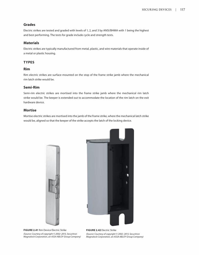
SECURING DEVICES | 117
c02.indd Page 117 03/03/2015 02:12:36:PM
Grades
Electric strikes are tested and graded with levels of 1, 2, and 3 by ANSI/BHMA with 1 being the highest
and best performing. The tests for grade include cycle and strength tests.
Materials
Electric strikes are typically manufactured from metal, plastic, and wire materials that operate inside of
a metal or plastic housing.
TYPES
Rim
Rim electric strikes are surface-mounted on the stop of the frame strike jamb where the mechanical
rim latch strike would be.
Semi-Rim
Semi-rim electric strikes are mortised into the frame strike jamb where the mechanical rim latch
strike would be. The keeper is extended out to accommodate the location of the rim latch on the exit
hardware device.
Mortise
Mortise electric strikes are mortised into the jamb of the frame strike, where the mechanical latch strike
would be, aligned so that the keeper of the strike accepts the latch of the locking device.
FIGURE 2.41 Rim Device Electric Strike
(Source: Courtesy of copyright © 2002–2013, Securitron Magnalock Corporation, an ASSA ABLOY Group Company)
FIGURE 2.42 Electric Strike
(Source: Courtesy of copyright © 2002–2013, Securitron Magnalock Corporation, an ASSA ABLOY Group Company)
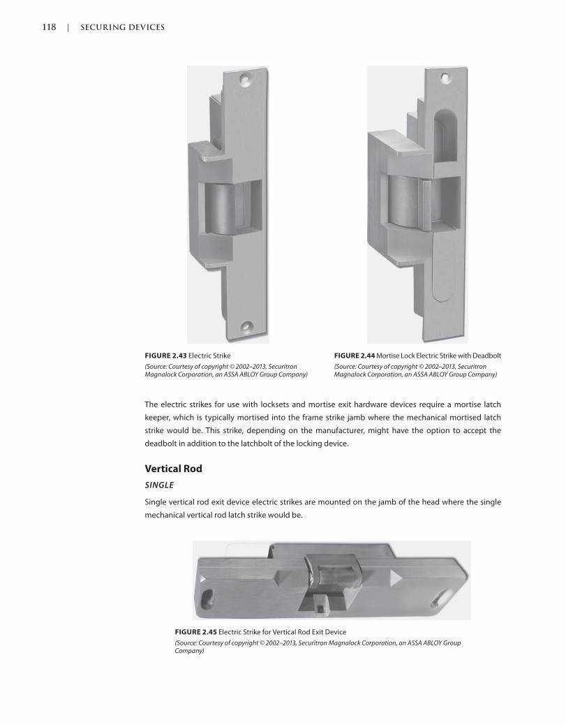
118 | SECURING DEVICES
c02.indd Page 118 03/03/2015 02:12:36:PM
The electric strikes for use with locksets and mortise exit hardware devices require a mortise latch
keeper, which is typically mortised into the frame strike jamb where the mechanical mortised latch
strike would be. This strike, depending on the manufacturer, might have the option to accept the
deadbolt in addition to the latchbolt of the locking device.
Vertical Rod
SINGLE
Single vertical rod exit device electric strikes are mounted on the jamb of the head where the single
mechanical vertical rod latch strike would be.
FIGURE 2.43 Electric Strike
(Source: Courtesy of copyright © 2002–2013, Securitron Magnalock Corporation, an ASSA ABLOY Group Company)
FIGURE 2.44 Mortise Lock Electric Strike with Deadbolt
(Source: Courtesy of copyright © 2002–2013, Securitron Magnalock Corporation, an ASSA ABLOY Group Company)
FIGURE 2.45 Electric Strike for Vertical Rod Exit Device
(Source: Courtesy of copyright © 2002–2013, Securitron Magnalock Corporation, an ASSA ABLOY Group Company)
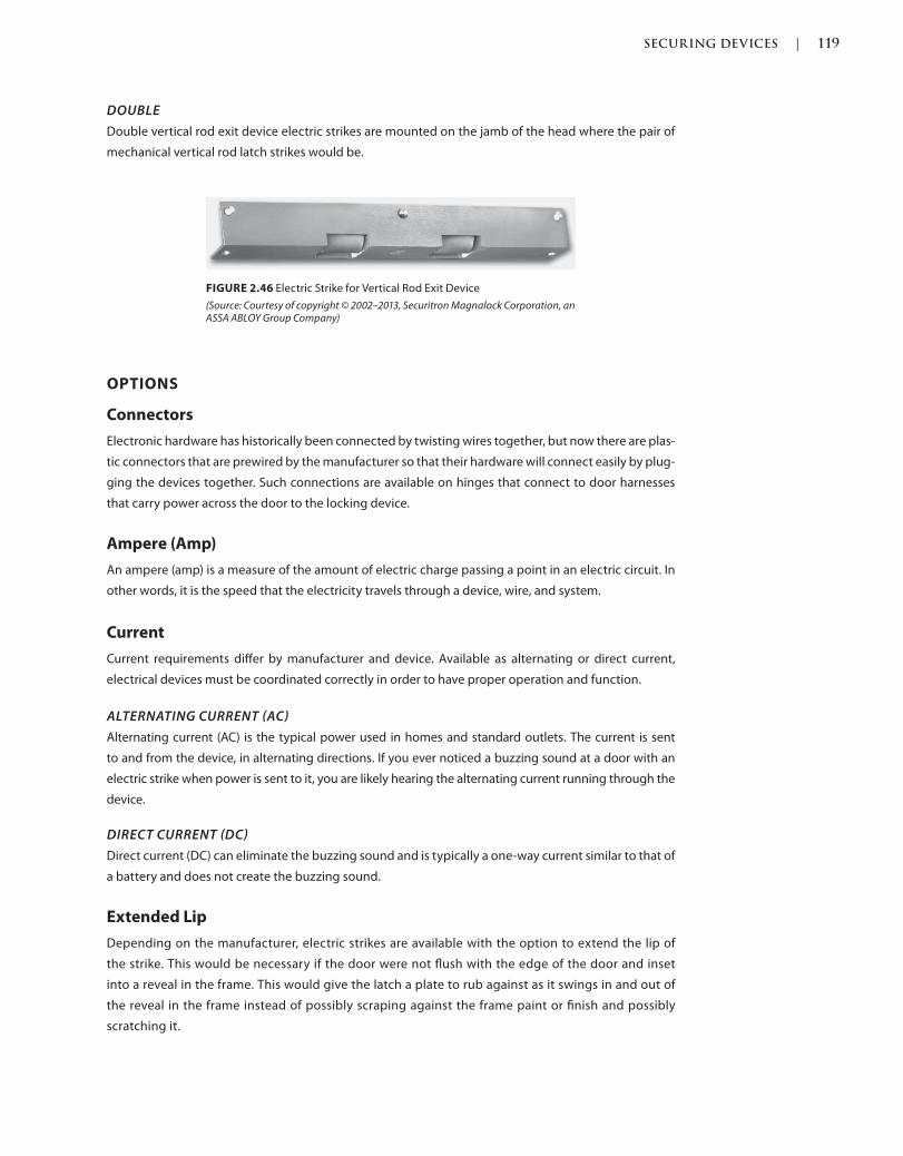
SECURING DEVICES | 119
c02.indd Page 119 03/03/2015 02:12:36:PM
DOUBLE
Double vertical rod exit device electric strikes are mounted on the jamb of the head where the pair of
mechanical vertical rod latch strikes would be.
OPTIONS
Connectors
Electronic hardware has historically been connected by twisting wires together, but now there are plas-
tic connectors that are prewired by the manufacturer so that their hardware will connect easily by plug-
ging the devices together. Such connections are available on hinges that connect to door harnesses
that carry power across the door to the locking device.
Ampere (Amp)
An ampere (amp) is a measure of the amount of electric charge passing a point in an electric circuit. In
other words, it is the speed that the electricity travels through a device, wire, and system.
Current
Current requirements differ by manufacturer and device. Available as alternating or direct current,
electrical devices must be coordinated correctly in order to have proper operation and function.
ALTERNATING CURRENT AC
Alternating current (AC) is the typical power used in homes and standard outlets. The current is sent
to and from the device, in alternating directions. If you ever noticed a buzzing sound at a door with an
electric strike when power is sent to it, you are likely hearing the alternating current running through the
device.
DIRECT CURRENT DC
Direct current (DC) can eliminate the buzzing sound and is typically a one-way current similar to that of
a battery and does not create the buzzing sound.
Extended Lip
Depending on the manufacturer, electric strikes are available with the option to extend the lip of
the strike. This would be necessary if the door were not flush with the edge of the door and inset
into a reveal in the frame. This would give the latch a plate to rub against as it swings in and out of
the reveal in the frame instead of possibly scraping against the frame paint or finish and possibly
scratching it.
FIGURE 2.46 Electric Strike for Vertical Rod Exit Device
(Source: Courtesy of copyright © 2002–2013, Securitron Magnalock Corporation, an ASSA ABLOY Group Company)
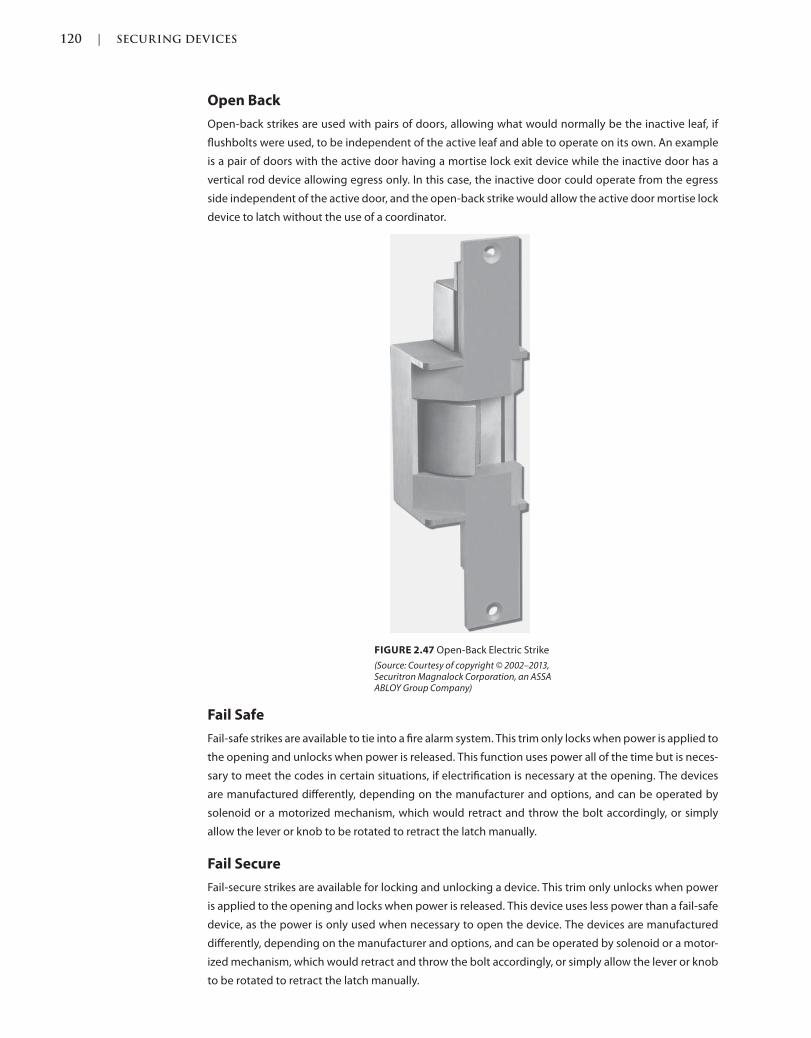
120 | SECURING DEVICES
c02.indd Page 120 03/03/2015 02:12:36:PM
Open Back
Open-back strikes are used with pairs of doors, allowing what would normally be the inactive leaf, if
flushbolts were used, to be independent of the active leaf and able to operate on its own. An example
is a pair of doors with the active door having a mortise lock exit device while the inactive door has a
vertical rod device allowing egress only. In this case, the inactive door could operate from the egress
side independent of the active door, and the open-back strike would allow the active door mortise lock
device to latch without the use of a coordinator.
Fail Safe
Fail-safe strikes are available to tie into a fire alarm system. This trim only locks when power is applied to
the opening and unlocks when power is released. This function uses power all of the time but is neces-
sary to meet the codes in certain situations, if electrification is necessary at the opening. The devices
are manufactured differently, depending on the manufacturer and options, and can be operated by
solenoid or a motorized mechanism, which would retract and throw the bolt accordingly, or simply
allow the lever or knob to be rotated to retract the latch manually.
Fail Secure
Fail-secure strikes are available for locking and unlocking a device. This trim only unlocks when power
is applied to the opening and locks when power is released. This device uses less power than a fail-safe
device, as the power is only used when necessary to open the device. The devices are manufactured
differently, depending on the manufacturer and options, and can be operated by solenoid or a motor-
ized mechanism, which would retract and throw the bolt accordingly, or simply allow the lever or knob
to be rotated to retract the latch manually.
FIGURE 2.47 Open-Back Electric Strike
(Source: Courtesy of copyright © 2002–2013, Securitron Magnalock Corporation, an ASSA ABLOY Group Company)
SECURING DEVICES | 121
c02.indd Page 121 03/03/2015 02:12:36:PM
Voltage
Voltage requirements differ by manufacturer and device. Available with various voltages such as 12 VAC
or DC, and 24 VAC or DC, devices must be coordinated correctly in order to have proper operation and
function. With that said, there are manufacturers that have devices that operate with multiple voltages,
so one would not need to coordinate them when purchasing the devices, but you should do so when
installing them, to be certain there are no errors and the devices are not ruined and left unusable.
QUANTITIES
Electric strikes are installed in single units with one strike per latch.
APPLICATIONS
Surface-Mounted
Electric strikes for use with rim exit hardware devices require a rim latch keeper, which is typically
surface-mounted on the stop of the frame strike jamb where the mechanical rim latch strike would be.
Electric strikes for use with vertical rod exit devices are mounted on the jamb of the head where the
mechanical vertical rod latch strike would be.
Mortised
Electric strikes for use with locksets and mortise exit hardware devices require a mortise latch keeper, which
is typically mortised into the frame strike jamb where the mechanical mortised latch strike would be.
INSTALLATION
An electric strike is typically installed on the frame or on the inactive leaf of a pair of doors, and the
latchbolt and/or deadbolt of the locking device is secured in the keeper of the strike. The latchbolt of
the locking device can be pushed through the keeper of the electric strike once the strike is released,
without requiring the latchbolt to be retracted by the handle or knob as with mechanical strikes.
If an electric strike is being installed on a stile and rail door, always confirm the lock stile dimension to
ensure that there is enough room to install the strike.
Fasteners
Electric strikes are typically installed with screw fasteners, which are available for wood or metal door
and frame material installation. Phillips and flat-head screws are available, depending on the manufac-
turer’s standard, and special screw heads are available as an option, including security, security stud,
and torx.
It is recommended that the proper fasteners be specified for efficient installation rather than relying on
a box of self-tapping screws, which might be more convenient for the installer.
Locations
Electric strikes should be installed at locations as recommended by industry standards and codes,
which are typically measured from the finished floor. Depending on the door and frame type, whether
it is considered standard or custom metal, wood, or aluminum, standards recommend starting the first
hinge as measured from the finished floor.
STANDARD STEEL DOORS AND FRAMES
Standard steel doors and frames are recommended to have the centerline of the strike on the frame
installed at 40 5/16 inches.
122 | SECURING DEVICES
c02.indd Page 122 03/03/2015 02:12:36:PM
CUSTOM STEEL DOORS AND FRAMES
Custom steel doors and frames are recommended to have the centerline of the strike on the frame
installed at 38 inches.
FLUSH WOOD DOORS AND FRAMES
Flush wood doors are recommended to have the strike on the frame installed at 40 5/16 inches.
Preparations
Electric strike preparations are typically machined at the factory, including the drilling and tapping of
screw holes. With metal doors and frames, the preparation is typically a cutout in the location where an
electric strike will be installed.
PANIC AND FIRE EXIT HARDWARE
Also Known As: Crash Bars, Exit Hardware, Panic Hardware
DESCRIPTION
Although similar in function and appearance, there is a major difference between panic hardware and
a fire exit device, whether or not they are specified and installed on a fire rated door.
Panic hardware is typically used for life safety, egress, and occupancy requirements. While fire exit
devices are typically used for the same reasons, in addition the door opening is fire rated. These devices
were tested in accordance with fire rating requirements and will bear the fire rated symbol to verify it
they are compliant.
Another difference between the devices is that panic hardware can be “dogged” in the open position
and a fire exit device cannot be. As mentioned earlier, a fire rated door must secure itself into the door
frame on its own when a fire occurs, and a fire rated dogged device would require the assistance of
someone to make that happen.
With that said, there is an option available from some manufacturers to electrically dog a device, where
the bolts are retracted and held electronically, typically by a solenoid, which is magnetic. This device
is wired, or tied, into the fire alarm system, and when the fire alarm is engaged, the power is cut, the
solenoid releases, the bolts retract, and the door is engaged and secured into the frame as required at
the time of the fire.
PROPERTIES
Panic and fire exit hardware can be manufactured with various configurations, aesthetics, functions,
and options.
Actuating Bar
There are three main types of panic and fire exit hardware actuating bars, which are depressed to
retract the latches of the device, allowing egress. As you can see from Figure 2.48, the actuating bars
have very different aesthetics and angles of projection from the face of the door.
There are some newer, simple, more aesthetically designed devices available that might meet egress
standards and codes for panic, but not necessarily fire exit requirements.
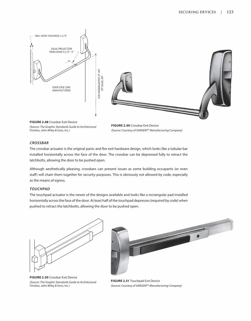
SECURING DEVICES | 123
c02.indd Page 123 03/03/2015 02:12:36:PM
CROSSBAR
The crossbar actuator is the original panic and fire exit hardware design, which looks like a tubular bar
installed horizontally across the face of the door. The crossbar can be depressed fully to retract the
latchbolts, allowing the door to be pushed open.
Although aesthetically pleasing, crossbars can present issues as some building occupants (or even
staff) will chain them together for security purposes. This is obviously not allowed by code, especially
as the means of egress.
TOUCHPAD
The touchpad actuator is the newer of the designs available and looks like a rectangular pad installed
horizontally across the face of the door. At least half of the touchpad depresses (required by code) when
pushed to retract the latchbolts, allowing the door to be pushed open.
FIGURE 2.48 Crossbar Exit Device
(Source: The Graphic Standards Guide to Architectural Finishes, John Wiley & Sons, Inc.)
FIGURE 2.49 Crossbar Exit Device
(Source: Courtesy of SARGENT® Manufacturing Company)
FIGURE 2.50 Crossbar Exit Device
(Source: The Graphic Standards Guide to Architectural Finishes, John Wiley & Sons, Inc.)
FIGURE 2.51 Touchpad Exit Device
(Source: Courtesy of SARGENT® Manufacturing Company)
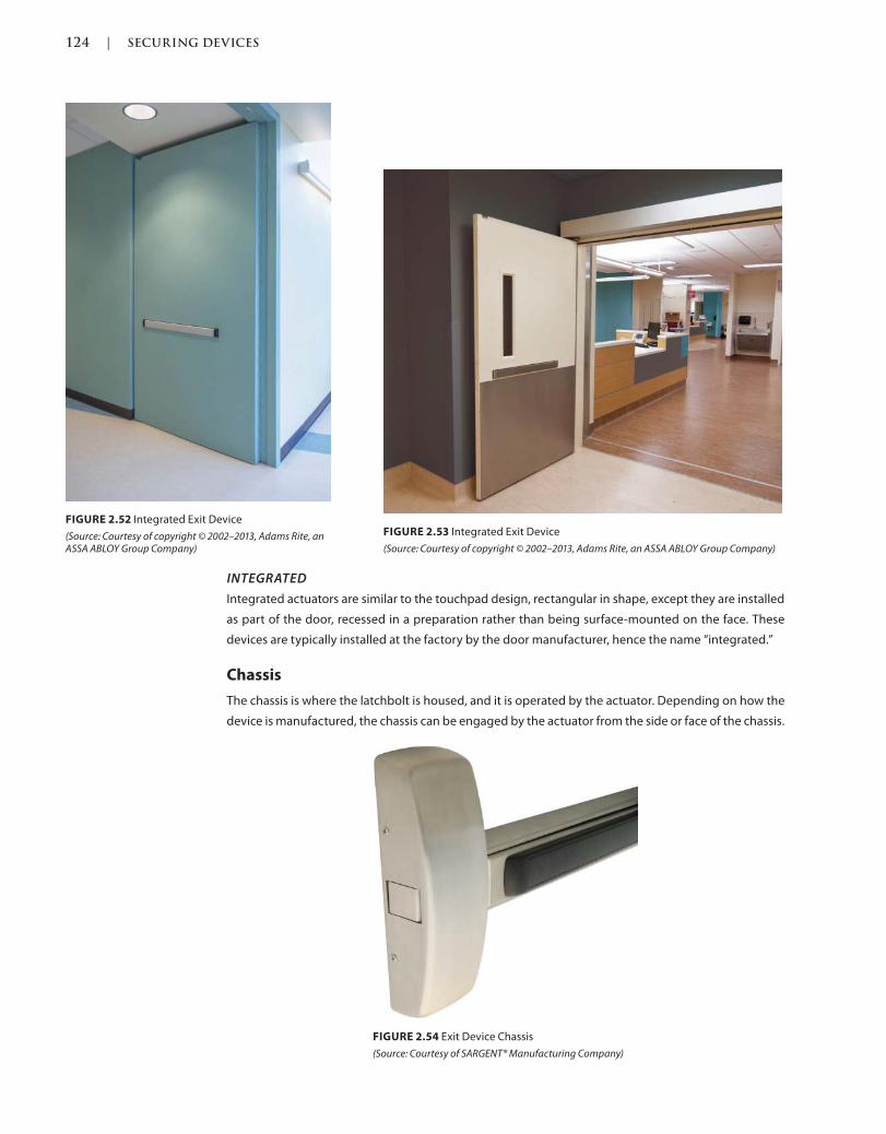
124 | SECURING DEVICES
c02.indd Page 124 03/03/2015 02:12:36:PM
INTEGRATED
Integrated actuators are similar to the touchpad design, rectangular in shape, except they are installed
as part of the door, recessed in a preparation rather than being surface-mounted on the face. These
devices are typically installed at the factory by the door manufacturer, hence the name “integrated.”
Chassis
The chassis is where the latchbolt is housed, and it is operated by the actuator. Depending on how the
device is manufactured, the chassis can be engaged by the actuator from the side or face of the chassis.
FIGURE 2.52 Integrated Exit Device
(Source: Courtesy of copyright © 2002–2013, Adams Rite, an ASSA ABLOY Group Company)
FIGURE 2.53 Integrated Exit Device
(Source: Courtesy of copyright © 2002–2013, Adams Rite, an ASSA ABLOY Group Company)
FIGURE 2.54 Exit Device Chassis
(Source: Courtesy of SARGENT® Manufacturing Company)
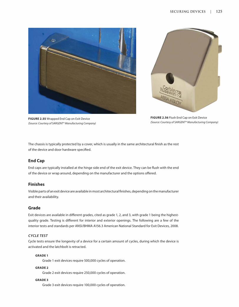
SECURING DEVICES | 125
c02.indd Page 125 03/03/2015 02:12:36:PM
The chassis is typically protected by a cover, which is usually in the same architectural finish as the rest
of the device and door hardware specified.
End Cap
End caps are typically installed at the hinge side end of the exit device. They can be flush with the end
of the device or wrap around, depending on the manufacturer and the options offered.
Finishes
Visible parts of an exit device are available in most architectural finishes, depending on the manufacturer
and their availability.
Grade
Exit devices are available in different grades, cited as grade 1, 2, and 3, with grade 1 being the highest-
quality grade. Testing is different for interior and exterior openings. The following are a few of the
interior tests and standards per ANSI/BHMA A156.3 American National Standard for Exit Devices, 2008.
CYCLE TEST
Cycle tests ensure the longevity of a device for a certain amount of cycles, during which the device is
activated and the latchbolt is retracted.
GRADE 1
Grade 1 exit devices require 500,000 cycles of operation.
GRADE 2
Grade 2 exit devices require 250,000 cycles of operation.
GRADE 3
Grade 3 exit devices require 100,000 cycles of operation.
FIGURE 2.55 Wrapped End Cap on Exit Device
(Source: Courtesy of SARGENT® Manufacturing Company)
FIGURE 2.56 Flush End Cap on Exit Device
(Source: Courtesy of SARGENT® Manufacturing Company)
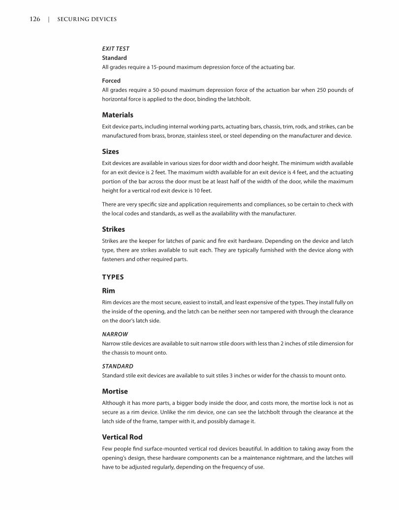
126 | SECURING DEVICES
c02.indd Page 126 03/03/2015 02:12:36:PM
EXIT TEST
Standard
All grades require a 15-pound maximum depression force of the actuating bar.
Forced
All grades require a 50-pound maximum depression force of the actuation bar when 250 pounds of
horizontal force is applied to the door, binding the latchbolt.
Materials
Exit device parts, including internal working parts, actuating bars, chassis, trim, rods, and strikes, can be
manufactured from brass, bronze, stainless steel, or steel depending on the manufacturer and device.
Sizes
Exit devices are available in various sizes for door width and door height. The minimum width available
for an exit device is 2 feet. The maximum width available for an exit device is 4 feet, and the actuating
portion of the bar across the door must be at least half of the width of the door, while the maximum
height for a vertical rod exit device is 10 feet.
There are very specific size and application requirements and compliances, so be certain to check with
the local codes and standards, as well as the availability with the manufacturer.
Strikes
Strikes are the keeper for latches of panic and fire exit hardware. Depending on the device and latch
type, there are strikes available to suit each. They are typically furnished with the device along with
fasteners and other required parts.
TYPES
Rim
Rim devices are the most secure, easiest to install, and least expensive of the types. They install fully on
the inside of the opening, and the latch can be neither seen nor tampered with through the clearance
on the door’s latch side.
NARROW
Narrow stile devices are available to suit narrow stile doors with less than 2 inches of stile dimension for
the chassis to mount onto.
STANDARD
Standard stile exit devices are available to suit stiles 3 inches or wider for the chassis to mount onto.
Mortise
Although it has more parts, a bigger body inside the door, and costs more, the mortise lock is not as
secure as a rim device. Unlike the rim device, one can see the latchbolt through the clearance at the
latch side of the frame, tamper with it, and possibly damage it.
Vertical Rod
Few people find surface-mounted vertical rod devices beautiful. In addition to taking away from the
opening’s design, these hardware components can be a maintenance nightmare, and the latches will
have to be adjusted regularly, depending on the frequency of use.
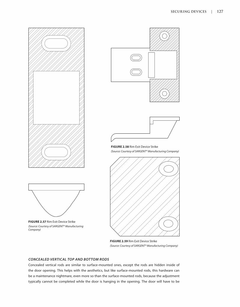
SECURING DEVICES | 127
c02.indd Page 127 03/03/2015 02:12:36:PM
FIGURE 2.57 Rim Exit Device Strike
(Source: Courtesy of SARGENT® Manufacturing Company)
FIGURE 2.58 Rim Exit Device Strike
(Source: Courtesy of SARGENT® Manufacturing Company)
FIGURE 2.59 Rim Exit Device Strike
(Source: Courtesy of SARGENT® Manufacturing Company)
CONCEALED VERTICAL TOP AND BOTTOM RODS
Concealed vertical rods are similar to surface-mounted ones, except the rods are hidden inside of
the door opening. This helps with the aesthetics, but like surface-mounted rods, this hardware can
be a maintenance nightmare, even more so than the surface-mounted rods, because the adjustment
typically cannot be completed while the door is hanging in the opening. The door will have to be
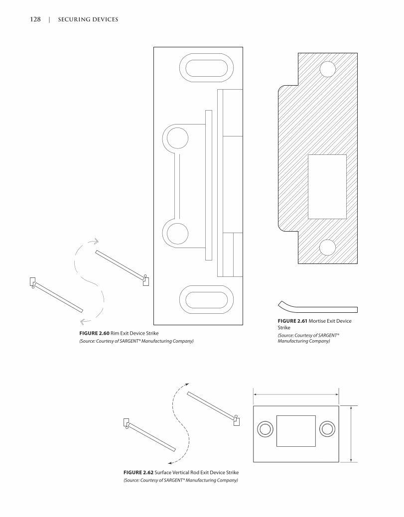
128 | SECURING DEVICES
c02.indd Page 128 03/03/2015 02:12:36:PM
FIGURE 2.60 Rim Exit Device Strike
(Source: Courtesy of SARGENT® Manufacturing Company)
FIGURE 2.61 Mortise Exit Device
Strike
(Source: Courtesy of SARGENT® Manufacturing Company)
FIGURE 2.62 Surface Vertical Rod Exit Device Strike
(Source: Courtesy of SARGENT® Manufacturing Company)
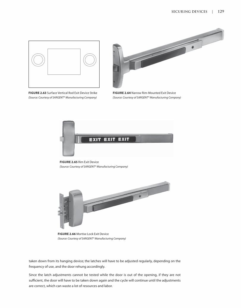
SECURING DEVICES | 129
c02.indd Page 129 03/03/2015 02:12:36:PM
FIGURE 2.66 Mortise Lock Exit Device
(Source: Courtesy of SARGENT® Manufacturing Company)
FIGURE 2.64 Narrow Rim-Mounted Exit Device
(Source: Courtesy of SARGENT® Manufacturing Company)
FIGURE 2.63 Surface Vertical Rod Exit Device Strike
(Source: Courtesy of SARGENT® Manufacturing Company)
FIGURE 2.65 Rim Exit Device
(Source: Courtesy of SARGENT® Manufacturing Company)
taken down from its hanging device; the latches will have to be adjusted regularly, depending on the
frequency of use, and the door rehung accordingly.
Since the latch adjustments cannot be tested while the door is out of the opening, if they are not
sufficient, the door will have to be taken down again and the cycle will continue until the adjustments
are correct, which can waste a lot of resources and labor.
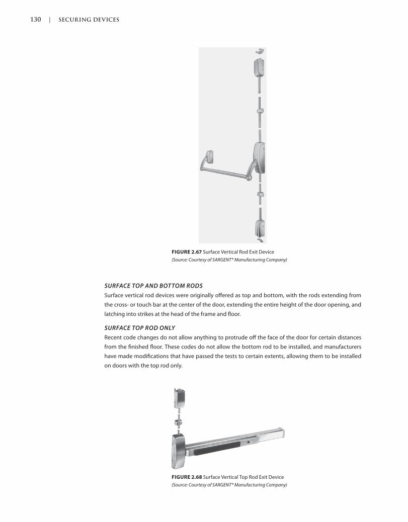
130 | SECURING DEVICES
c02.indd Page 130 03/03/2015 02:12:36:PM
SURFACE TOP AND BOTTOM RODS
Surface vertical rod devices were originally offered as top and bottom, with the rods extending from
the cross- or touch bar at the center of the door, extending the entire height of the door opening, and
latching into strikes at the head of the frame and floor.
SURFACE TOP ROD ONLY
Recent code changes do not allow anything to protrude off the face of the door for certain distances
from the finished floor. These codes do not allow the bottom rod to be installed, and manufacturers
have made modifications that have passed the tests to certain extents, allowing them to be installed
on doors with the top rod only.
FIGURE 2.67 Surface Vertical Rod Exit Device
(Source: Courtesy of SARGENT® Manufacturing Company)
FIGURE 2.68 Surface Vertical Top Rod Exit Device
(Source: Courtesy of SARGENT® Manufacturing Company)
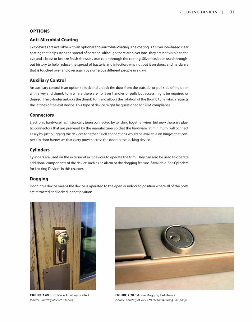
SECURING DEVICES | 131
c02.indd Page 131 03/03/2015 02:12:36:PM
OPTIONS
Anti-Microbial Coating
Exit devices are available with an optional anti-microbial coating. The coating is a silver ion–based clear
coating that helps stop the spread of bacteria. Although there are silver ions, they are not visible to the
eye and a brass or bronze finish shows its true color through the coating. Silver has been used through-
out history to help reduce the spread of bacteria and infection; why not put it on doors and hardware
that is touched over and over again by numerous different people in a day?
Auxiliary Control
An auxiliary control is an option to lock and unlock the door from the outside, or pull side of the door,
with a key and thumb turn where there are no lever handles or pulls but access might be required or
desired. The cylinder unlocks the thumb turn and allows the rotation of the thumb turn, which retracts
the latches of the exit device. This type of device might be questioned for ADA compliance.
Connectors
Electronic hardware has historically been connected by twisting together wires, but now there are plas-
tic connectors that are prewired by the manufacturer so that the hardware, at minimum, will connect
easily by just plugging the devices together. Such connections would be available on hinges that con-
nect to door harnesses that carry power across the door to the locking device.
Cylinders
Cylinders are used on the exterior of exit devices to operate the trim. They can also be used to operate
additional components of the device such as an alarm or the dogging feature if available. See Cylinders
for Locking Devices in this chapter.
Dogging
Dogging a device means the device is operated to the open or unlocked position where all of the bolts
are retracted and locked in that position.
FIGURE 2.69 Exit Device Auxiliary Control
(Source: Courtesy of Scott J. Tobias)
FIGURE 2.70 Cylinder Dogging Exit Device
(Source: Courtesy of SARGENT® Manufacturing Company)
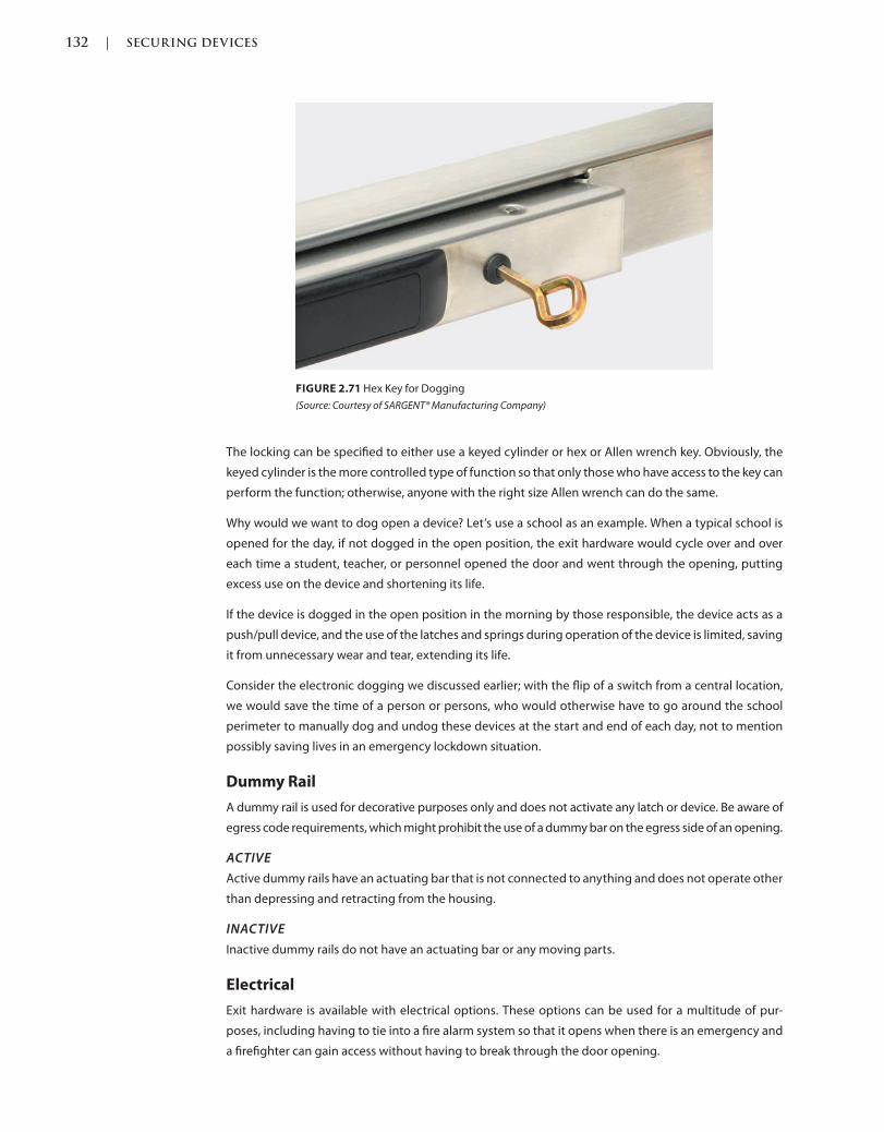
132 | SECURING DEVICES
c02.indd Page 132 03/03/2015 02:12:36:PM
The locking can be specified to either use a keyed cylinder or hex or Allen wrench key. Obviously, the
keyed cylinder is the more controlled type of function so that only those who have access to the key can
perform the function; otherwise, anyone with the right size Allen wrench can do the same.
Why would we want to dog open a device? Let’s use a school as an example. When a typical school is
opened for the day, if not dogged in the open position, the exit hardware would cycle over and over
each time a student, teacher, or personnel opened the door and went through the opening, putting
excess use on the device and shortening its life.
If the device is dogged in the open position in the morning by those responsible, the device acts as a
push/pull device, and the use of the latches and springs during operation of the device is limited, saving
it from unnecessary wear and tear, extending its life.
Consider the electronic dogging we discussed earlier; with the flip of a switch from a central location,
we would save the time of a person or persons, who would otherwise have to go around the school
perimeter to manually dog and undog these devices at the start and end of each day, not to mention
possibly saving lives in an emergency lockdown situation.
Dummy Rail
A dummy rail is used for decorative purposes only and does not activate any latch or device. Be aware of
egress code requirements, which might prohibit the use of a dummy bar on the egress side of an opening.
ACTIVE
Active dummy rails have an actuating bar that is not connected to anything and does not operate other
than depressing and retracting from the housing.
INACTIVE
Inactive dummy rails do not have an actuating bar or any moving parts.
Electrical
Exit hardware is available with electrical options. These options can be used for a multitude of pur-
poses, including having to tie into a fire alarm system so that it opens when there is an emergency and
a firefighter can gain access without having to break through the door opening.
FIGURE 2.71 Hex Key for Dogging
(Source: Courtesy of SARGENT® Manufacturing Company)
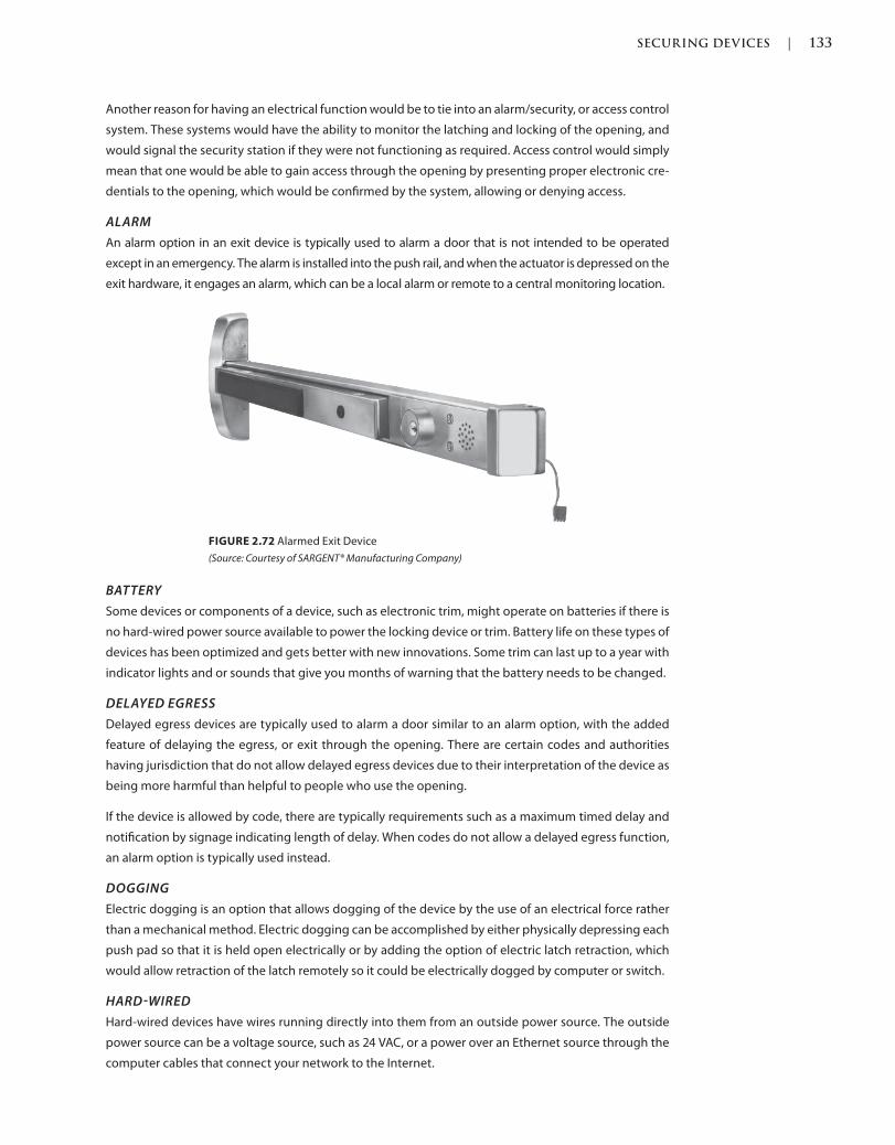
SECURING DEVICES | 133
c02.indd Page 133 03/03/2015 02:12:36:PM
Another reason for having an electrical function would be to tie into an alarm/security, or access control
system. These systems would have the ability to monitor the latching and locking of the opening, and
would signal the security station if they were not functioning as required. Access control would simply
mean that one would be able to gain access through the opening by presenting proper electronic cre-
dentials to the opening, which would be confirmed by the system, allowing or denying access.
ALARM
An alarm option in an exit device is typically used to alarm a door that is not intended to be operated
except in an emergency. The alarm is installed into the push rail, and when the actuator is depressed on the
exit hardware, it engages an alarm, which can be a local alarm or remote to a central monitoring location.
FIGURE 2.72 Alarmed Exit Device
(Source: Courtesy of SARGENT® Manufacturing Company)
BATTERY
Some devices or components of a device, such as electronic trim, might operate on batteries if there is
no hard-wired power source available to power the locking device or trim. Battery life on these types of
devices has been optimized and gets better with new innovations. Some trim can last up to a year with
indicator lights and or sounds that give you months of warning that the battery needs to be changed.
DELAYED EGRESS
Delayed egress devices are typically used to alarm a door similar to an alarm option, with the added
feature of delaying the egress, or exit through the opening. There are certain codes and authorities
having jurisdiction that do not allow delayed egress devices due to their interpretation of the device as
being more harmful than helpful to people who use the opening.
If the device is allowed by code, there are typically requirements such as a maximum timed delay and
notification by signage indicating length of delay. When codes do not allow a delayed egress function,
an alarm option is typically used instead.
DOGGING
Electric dogging is an option that allows dogging of the device by the use of an electrical force rather
than a mechanical method. Electric dogging can be accomplished by either physically depressing each
push pad so that it is held open electrically or by adding the option of electric latch retraction, which
would allow retraction of the latch remotely so it could be electrically dogged by computer or switch.
HARDWIRED
Hard-wired devices have wires running directly into them from an outside power source. The outside
power source can be a voltage source, such as 24 VAC, or a power over an Ethernet source through the
computer cables that connect your network to the Internet.

134 | SECURING DEVICES
c02.indd Page 134 03/03/2015 02:12:36:PM
INTEGRATED WIEGAND
Panic and fire exit device trim is available with an integrated Wiegand card reader device. This reader
is a proximity type, where the card is presented within proximity of the reader and is read by radio
frequency rather than having to make the card physically contact the surface of the reader.
INTELLIGENCE
Exit devices can be equipped with intelligence, similar to that of your automobile. The newer the
automobile, the more intelligent they become with what is called CAN bus technology. Have you
ever noticed that, when you turn the key or push the ignition button, the lights flash and the horn
beeps almost talking to each other? That is CAN bus—CAN, short for controller area network,
is a standard that allows devices to communicate with each other without a host computer or
software.
LATCHBOLT MONITORING
Latchbolt monitoring is an electrified option that allows the monitoring of the latchbolt position,
whether extended or retracted. This allows the signaling of any devices that have not extended and
secured into the strike so that this can be followed up with in person to rectify the situation.
LEVER MONITORING
Lever monitoring is an electrified option that allows the monitoring of the lever handle position,
whether rotated or in the rest position. This allows the signaling of any lever handle that is in the rotated
position, indicating that the latchbolt is likely retracted and not secure in the strike.
LATCH RETRACTION
Electric latch retraction allows the remote electronic retraction and extension of the exit hardware
latchbolt. The operation can be accomplished by computer, a switch, or credentials such as a card and
reader. When the signal is initiated, the latch of the device is retracted so that the door can be pulled or
pushed open without having to retract the push pad from the inside or rotate a lever from the outside
of an exit hardware device.
POWER OVER ETHERNET
Devices that are powered over Ethernet are energized by the Ethernet cable that hard-wires the
computers to their network and the Internet, instead of having a separate voltage power source. The
advantages of this network is low power consumption and that the network and door monitors are
always live and talking to the system, ready to alert one of any suspicious activity.
REQUEST TO EXIT SWITCH
Request to exit switches are an electrified option available to shunt an alarm during an authorized
exit. If a door has a local or remote alarmed exit hardware device, door and frame signal switch,
lever, or latchbolt monitoring switch, a request to exit switch sends a signal to the contact, alarm,
or computer stating that the doorway is being accessed from the exit side and that no credentials
are required. This shunts the alarm, allowing the person to go through without having to present
electronic credentials.
TRIM
Electrified trim is available on the outside of an exit device door so that a door can be accessed from the
outside with the use of an electronic access control system. Typically rigid, when a switch such as a card
reader authorizes the credentials presented to it, the trim unlocks and is able to be rotated to retract
the latchbolt, pull the door forward, and gain entry to the space.
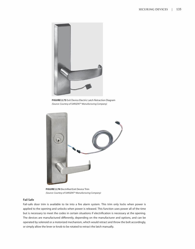
SECURING DEVICES | 135
c02.indd Page 135 03/03/2015 02:12:36:PM
FIGURE 2.73 Exit Device Electric Latch Retraction Diagram
(Source: Courtesy of SARGENT® Manufacturing Company)
FIGURE 2.74 Electrified Exit Device Trim
(Source: Courtesy of SARGENT® Manufacturing Company)
Fail Safe
Fail-safe door trim is available to tie into a fire alarm system. This trim only locks when power is
applied to the opening and unlocks when power is released. This function uses power all of the time
but is necessary to meet the codes in certain situations if electrification is necessary at the opening.
The devices are manufactured differently, depending on the manufacturer and options, and can be
operated by solenoid or a motorized mechanism, which would retract and throw the bolt accordingly,
or simply allow the lever or knob to be rotated to retract the latch manually.
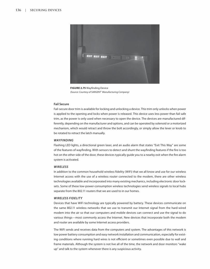
136 | SECURING DEVICES
c02.indd Page 136 03/03/2015 02:12:36:PM
Fail Secure
Fail-secure door trim is available for locking and unlocking a device. This trim only unlocks when power
is applied to the opening and locks when power is released. This device uses less power than fail safe
trim, as the power is only used when necessary to open the device. The devices are manufactured dif-
ferently, depending on the manufacturer and options, and can be operated by solenoid or a motorized
mechanism, which would retract and throw the bolt accordingly, or simply allow the lever or knob to
be rotated to retract the latch manually.
WAYFINDING
Flashing LED lights, a directional green laser, and an audio alarm that states “Exit This Way” are some
of the features of wayfinding. With sensors to detect and shunt the wayfinding features if the fire is too
hot on the other side of the door, these devices typically guide you to a nearby exit when the fire alarm
system is activated.
WIRELESS
In addition to the common household wireless fidelity (WiFi) that we all know and use for our wireless
Internet access with the use of a wireless router connected to the modem, there are other wireless
technologies available and incorporated into many existing mechanics, including electronic door lock-
sets. Some of these low-power-consumption wireless technologies send wireless signals to local hubs
separate from the 802.11 routers that we are used to in our homes.
WIRELESS FIDELITY
Devices that have WiFi technology are typically powered by battery. These devices communicate on
the same 802.11 wireless networks that we use to transmit our Internet signal from the hard-wired
modem into the air so that our computers and mobile devices can connect and use the signal to do
various things—most commonly access the Internet. New devices that incorporate both the modem
and router are available by some Internet access providers.
The WiFi sends and receives data from the computers and system. The advantages of this network is
low power battery consumption and easy network installation and communication, especially for exist-
ing conditions where running hard wires is not efficient or sometimes even possible due to wall and
frame materials. Although the system is not live all of the time, the network and door monitors “wake
up” and talk to the system whenever there is any suspicious activity.
FIGURE 2.75 Wayfinding Device
(Source: Courtesy of SARGENT® Manufacturing Company)
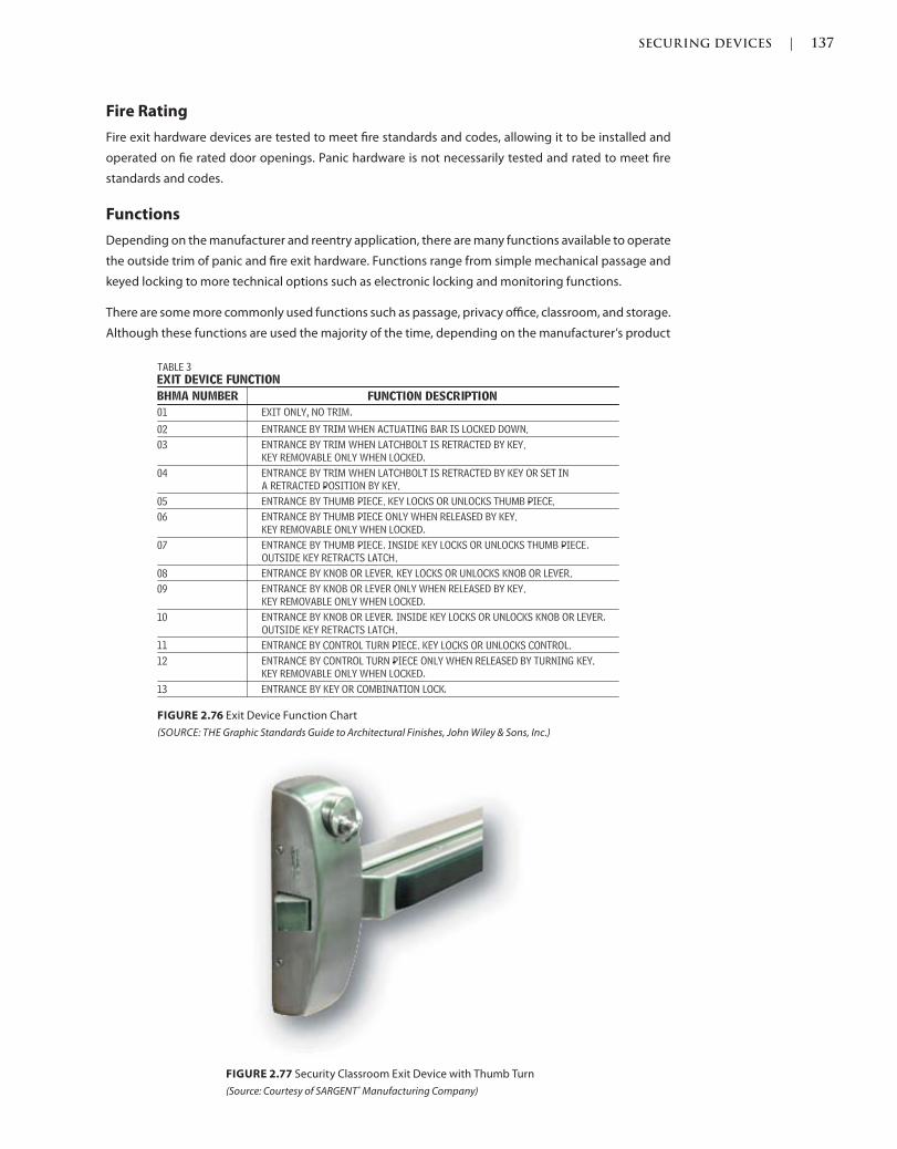
SECURING DEVICES | 137
c02.indd Page 137 03/03/2015 02:12:36:PM
Fire Rating
Fire exit hardware devices are tested to meet fire standards and codes, allowing it to be installed and
operated on fie rated door openings. Panic hardware is not necessarily tested and rated to meet fire
standards and codes.
Functions
Depending on the manufacturer and reentry application, there are many functions available to operate
the outside trim of panic and fire exit hardware. Functions range from simple mechanical passage and
keyed locking to more technical options such as electronic locking and monitoring functions.
There are some more commonly used functions such as passage, privacy office, classroom, and storage.
Although these functions are used the majority of the time, depending on the manufacturer’s product
FIGURE 2.76 Exit Device Function Chart
SOURCE: THE Graphic Standards Guide to Architectural Finishes, John Wiley & Sons, Inc.)
FIGURE 2.77 Security Classroom Exit Device with Thumb Turn
(Source: Courtesy of SARGENT® Manufacturing Company)
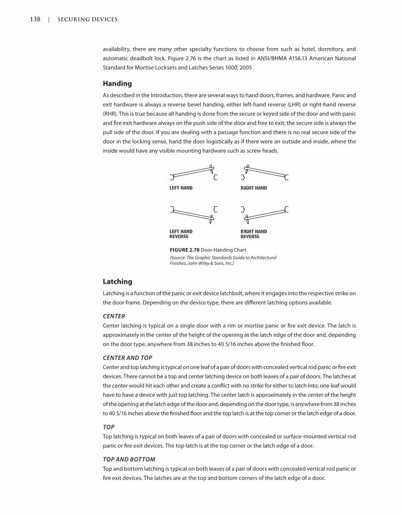
138 | SECURING DEVICES
c02.indd Page 138 03/03/2015 02:12:36:PM
availability, there are many other specialty functions to choose from such as hotel, dormitory, and
automatic deadbolt lock. Figure 2.76 is the chart as listed in ANSI/BHMA A156.13 American National
Standard for Mortise Locksets and Latches Series 1000, 2005
Handing
As described in the Introduction, there are several ways to hand doors, frames, and hardware. Panic and
exit hardware is always a reverse bevel handing, either left-hand reverse (LHR) or right-hand reverse
(RHR). This is true because all handing is done from the secure or keyed side of the door and with panic
and fire exit hardware always on the push side of the door and free to exit; the secure side is always the
pull side of the door. If you are dealing with a passage function and there is no real secure side of the
door in the locking sense, hand the door logistically as if there were an outside and inside, where the
inside would have any visible mounting hardware such as screw heads.
FIGURE 2.78 Door-Handing Chart
(Source: The Graphic Standards Guide to Architectural Finishes, John Wiley & Sons, Inc.)
Latching
Latching is a function of the panic or exit device latchbolt, where it engages into the respective strike on
the door frame. Depending on the device type, there are different latching options available.
CENTER
Center latching is typical on a single door with a rim or mortise panic or fire exit device. The latch is
approximately in the center of the height of the opening at the latch edge of the door and, depending
on the door type, anywhere from 38 inches to 40 5/16 inches above the finished floor.
CENTER AND TOP
Center and top latching is typical on one leaf of a pair of doors with concealed vertical rod panic or fire exit
devices. There cannot be a top and center latching device on both leaves of a pair of doors. The latches at
the center would hit each other and create a conflict with no strike for either to latch into; one leaf would
have to have a device with just top latching. The center latch is approximately in the center of the height
of the opening at the latch edge of the door and, depending on the door type, is anywhere from 38 inches
to 40 5/16 inches above the finished floor and the top latch is at the top corner or the latch edge of a door.
TOP
Top latching is typical on both leaves of a pair of doors with concealed or surface-mounted vertical rod
panic or fire exit devices. The top latch is at the top corner or the latch edge of a door.
TOP AND BOTTOM
Top and bottom latching is typical on both leaves of a pair of doors with concealed vertical rod panic or
fire exit devices. The latches are at the top and bottom corners of the latch edge of a door.
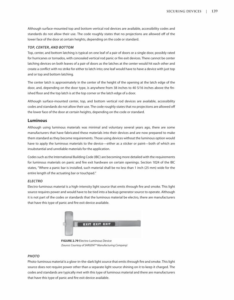
SECURING DEVICES | 139
c02.indd Page 139 03/03/2015 02:12:36:PM
Although surface-mounted top and bottom vertical rod devices are available, accessibility codes and
standards do not allow their use. The code roughly states that no projections are allowed off of the
lower face of the door at certain heights, depending on the code or standard.
TOP, CENTER, AND BOTTOM
Top, center, and bottom latching is typical on one leaf of a pair of doors or a single door, possibly rated
for hurricanes or tornados, with concealed vertical rod panic or fire exit devices. There cannot be center
latching devices on both leaves of a pair of doors as the latches at the center would hit each other and
create a conflict with no strike for either to latch into; one leaf would have to have a device with just top
and or top and bottom latching.
The center latch is approximately in the center of the height of the opening at the latch edge of the
door, and, depending on the door type, is anywhere from 38 inches to 40 5/16 inches above the fin-
ished floor and the top latch is at the top corner or the latch edge of a door.
Although surface-mounted center, top, and bottom vertical rod devices are available, accessibility
codes and standards do not allow their use. The code roughly states that no projections are allowed off
the lower face of the door at certain heights, depending on the code or standard.
Luminous
Although using luminous materials was minimal and voluntary several years ago, there are some
manufacturers that have fabricated these materials into their devices and are now prepared to make
them standard as they become requirements. Those using devices without the luminous option would
have to apply the luminous materials to the device—either as a sticker or paint—both of which are
insubstantial and unreliable materials for the application.
Codes such as the International Building Code (IBC) are becoming more detailed with the requirements
for luminous materials on panic and fire exit hardware on certain openings. Section 1024 of the IBC
states, “Where a panic bar is installed, such material shall be no less than 1 inch (25 mm) wide for the
entire length of the actuating bar or touchpad.”
ELECTRO
Electro-luminous material is a high-intensity light source that emits through fire and smoke. This light
source requires power and would have to be tied into a backup generator source to operate. Although
it is not part of the codes or standards that the luminous material be electro, there are manufacturers
that have this type of panic and fire exit device available.
FIGURE 2.79 Electro-Luminous Device
(Source: Courtesy of SARGENT® Manufacturing Company)
PHOTO
Photo-luminous material is a glow-in-the-dark light source that emits through fire and smoke. This light
source does not require power other than a separate light source shining on it to keep it charged. The
codes and standards are typically met with this type of luminous material and there are manufacturers
that have this type of panic and fire exit device available.
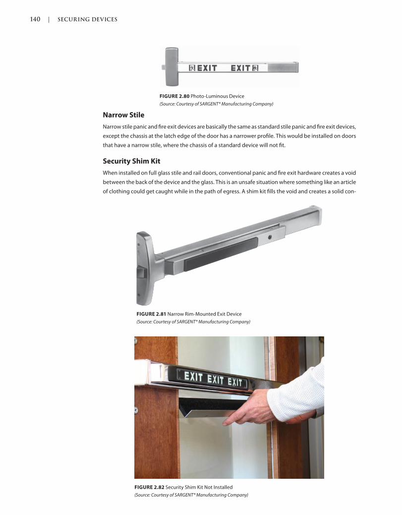
140 | SECURING DEVICES
c02.indd Page 140 03/03/2015 02:12:36:PM
FIGURE 2.80 Photo-Luminous Device
(Source: Courtesy of SARGENT® Manufacturing Company)
Narrow Stile
Narrow stile panic and fire exit devices are basically the same as standard stile panic and fire exit devices,
except the chassis at the latch edge of the door has a narrower profile. This would be installed on doors
that have a narrow stile, where the chassis of a standard device will not fit.
Security Shim Kit
When installed on full glass stile and rail doors, conventional panic and fire exit hardware creates a void
between the back of the device and the glass. This is an unsafe situation where something like an article
of clothing could get caught while in the path of egress. A shim kit fills the void and creates a solid con-
FIGURE 2.81 Narrow Rim-Mounted Exit Device
(Source: Courtesy of SARGENT® Manufacturing Company)
FIGURE 2.82 Security Shim Kit Not Installed
(Source: Courtesy of SARGENT® Manufacturing Company)
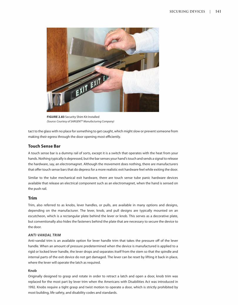
SECURING DEVICES | 141
c02.indd Page 141 03/03/2015 02:12:36:PM
tact to the glass with no place for something to get caught, which might slow or prevent someone from
making their egress through the door opening most efficiently.
Touch Sense Bar
A touch sense bar is a dummy rail of sorts, except it is a switch that operates with the heat from your
hands. Nothing typically is depressed, but the bar senses your hand’s touch and sends a signal to release
the hardware, say, an electromagnet. Although the movement does nothing, there are manufacturers
that offer touch sense bars that do depress for a more realistic exit hardware feel while exiting the door.
Similar to the tube mechanical exit hardware, there are touch sense tube panic hardware devices
available that release an electrical component such as an electromagnet, when the hand is sensed on
the push rail.
Trim
Trim, also referred to as knobs, lever handles, or pulls, are available in many options and designs,
depending on the manufacturer. The lever, knob, and pull designs are typically mounted on an
escutcheon, which is a rectangular plate behind the lever or knob. This serves as a decorative plate,
but conventionally also hides the fasteners behind the plate that are necessary to secure the device to
the door.
ANTIVANDAL TRIM
Anti-vandal trim is an available option for lever handle trim that takes the pressure off of the lever
handle. When an amount of pressure predetermined when the device is manufactured is applied to a
rigid or locked lever handle, the lever drops and separates itself from the stem so that the spindle and
internal parts of the exit device do not get damaged. The lever can be reset by lifting it back in place,
where the lever will operate the latch as required.
Knob
Originally designed to grasp and rotate in order to retract a latch and open a door, knob trim was
replaced for the most part by lever trim when the Americans with Disabilities Act was introduced in
1992. Knobs require a tight grasp and twist motion to operate a door, which is strictly prohibited by
most building, life safety, and disability codes and standards.
FIGURE 2.83 Security Shim Kit Installed
(Source: Courtesy of SARGENT® Manufacturing Company)

142 | SECURING DEVICES
c02.indd Page 142 03/03/2015 02:12:36:PM
Lever
Designed in the shape of a lever handle, these devices have met some of the guidelines and give the
opening a more conventional aesthetic than that of solely a healthcare facility. Some manufacturers
have more options and have enhanced on the operation, guideline standards, and aesthetics of the
device.
DECORATIVE
Trim can also be an aesthetic component of the panic or fire exit hardware outside trim. Some
manufacturers offer many lever handle design choices for all hardware types; some have suites that
allow consistent design on all hardware types including panic and fire exit hardware. Other matching
lever types include mortise locksets, electronic access control locksets, and tubular passage, privacy,
and dummy trim. There are also suites of hardware available that include lever handles for locksets, pull
handles for glass and sliding doors, drawer pulls, door stops, coat hooks, and hinges. With coordination,
this would give the entire opening, interior, and building a consistent door opening design.
ELECTRIFIED
Electrified trim is available on the outside of an exit device door so that a door can be accessed from
the outside with the use of an electronic access control system. Typically rigid, when a switch such as
FIGURE 2.84 Lever Handle
(Source: Courtesy of SARGENT® Manufacturing Company)
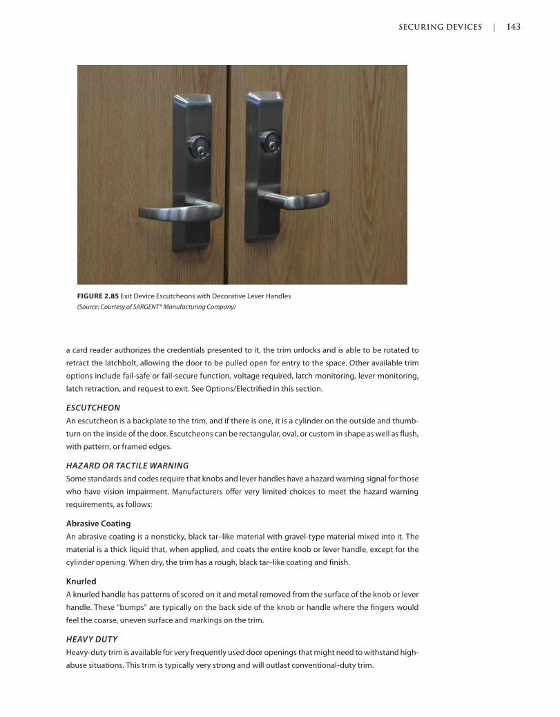
SECURING DEVICES | 143
c02.indd Page 143 03/03/2015 02:12:36:PM
a card reader authorizes the credentials presented to it, the trim unlocks and is able to be rotated to
retract the latchbolt, allowing the door to be pulled open for entry to the space. Other available trim
options include fail-safe or fail-secure function, voltage required, latch monitoring, lever monitoring,
latch retraction, and request to exit. See Options/Electrified in this section.
ESCUTCHEON
An escutcheon is a backplate to the trim, and if there is one, it is a cylinder on the outside and thumb-
turn on the inside of the door. Escutcheons can be rectangular, oval, or custom in shape as well as flush,
with pattern, or framed edges.
HAZARD OR TACTILE WARNING
Some standards and codes require that knobs and lever handles have a hazard warning signal for those
who have vision impairment. Manufacturers offer very limited choices to meet the hazard warning
requirements, as follows:
Abrasive Coating
An abrasive coating is a nonsticky, black tar–like material with gravel-type material mixed into it. The
material is a thick liquid that, when applied, and coats the entire knob or lever handle, except for the
cylinder opening. When dry, the trim has a rough, black tar–like coating and finish.
Knurled
A knurled handle has patterns of scored on it and metal removed from the surface of the knob or lever
handle. These “bumps” are typically on the back side of the knob or handle where the fingers would
feel the coarse, uneven surface and markings on the trim.
HEAVY DUTY
Heavy-duty trim is available for very frequently used door openings that might need to withstand high-
abuse situations. This trim is typically very strong and will outlast conventional-duty trim.
FIGURE 2.85 Exit Device Escutcheons with Decorative Lever Handles
(Source: Courtesy of SARGENT® Manufacturing Company)
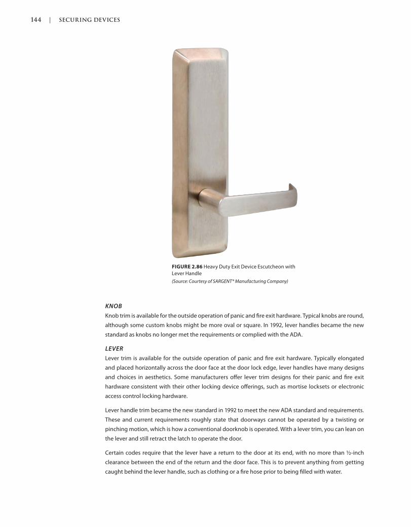
144 | SECURING DEVICES
c02.indd Page 144 03/03/2015 02:12:36:PM
KNOB
Knob trim is available for the outside operation of panic and fire exit hardware. Typical knobs are round,
although some custom knobs might be more oval or square. In 1992, lever handles became the new
standard as knobs no longer met the requirements or complied with the ADA.
LEVER
Lever trim is available for the outside operation of panic and fire exit hardware. Typically elongated
and placed horizontally across the door face at the door lock edge, lever handles have many designs
and choices in aesthetics. Some manufacturers offer lever trim designs for their panic and fire exit
hardware consistent with their other locking device offerings, such as mortise locksets or electronic
access control locking hardware.
Lever handle trim became the new standard in 1992 to meet the new ADA standard and requirements.
These and current requirements roughly state that doorways cannot be operated by a twisting or
pinching motion, which is how a conventional doorknob is operated. With a lever trim, you can lean on
the lever and still retract the latch to operate the door.
Certain codes require that the lever have a return to the door at its end, with no more than ½-inch
clearance between the end of the return and the door face. This is to prevent anything from getting
caught behind the lever handle, such as clothing or a fire hose prior to being filled with water.
FIGURE 2.86 Heavy Duty Exit Device Escutcheon with
Lever Handle
(Source: Courtesy of SARGENT® Manufacturing Company)
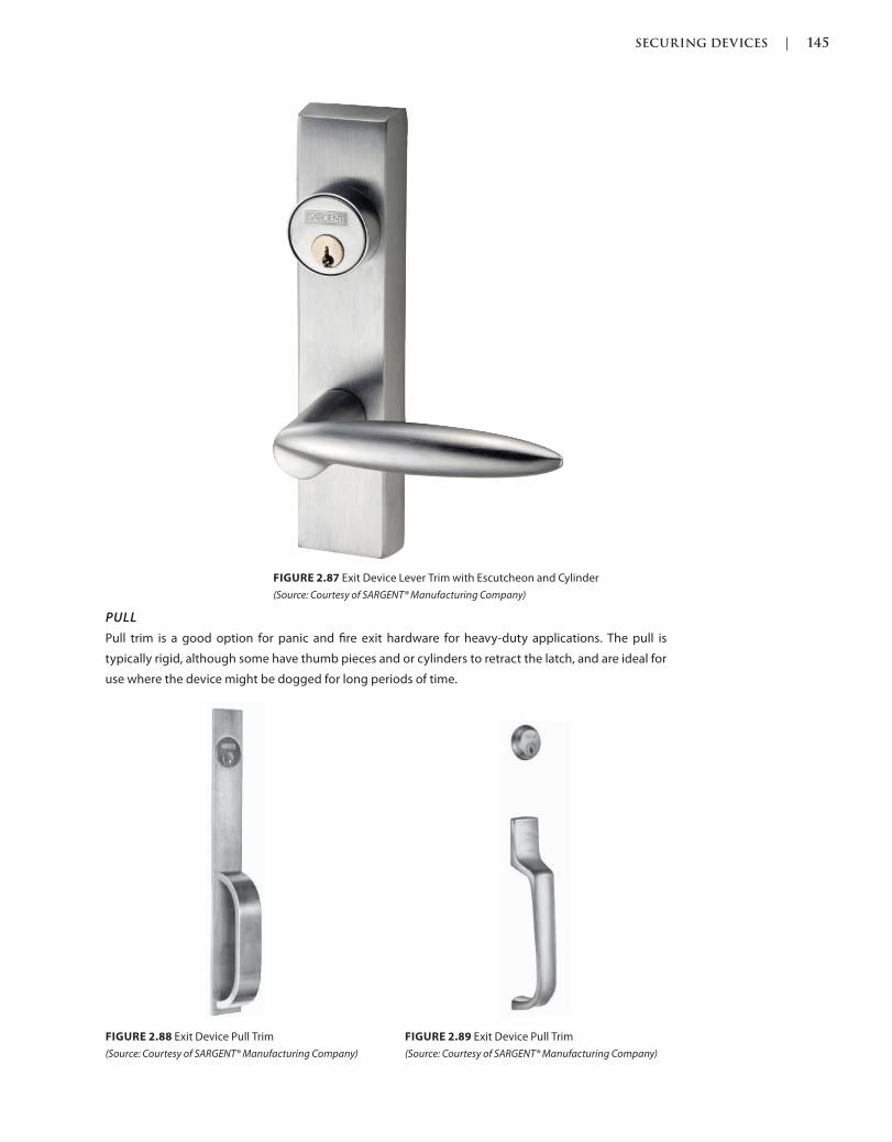
SECURING DEVICES | 145
c02.indd Page 145 03/03/2015 02:12:36:PM
PULL
Pull trim is a good option for panic and fire exit hardware for heavy-duty applications. The pull is
typically rigid, although some have thumb pieces and or cylinders to retract the latch, and are ideal for
use where the device might be dogged for long periods of time.
FIGURE 2.88 Exit Device Pull Trim
(Source: Courtesy of SARGENT® Manufacturing Company)
FIGURE 2.89 Exit Device Pull Trim
(Source: Courtesy of SARGENT® Manufacturing Company)
FIGURE 2.87 Exit Device Lever Trim with Escutcheon and Cylinder
(Source: Courtesy of SARGENT® Manufacturing Company)
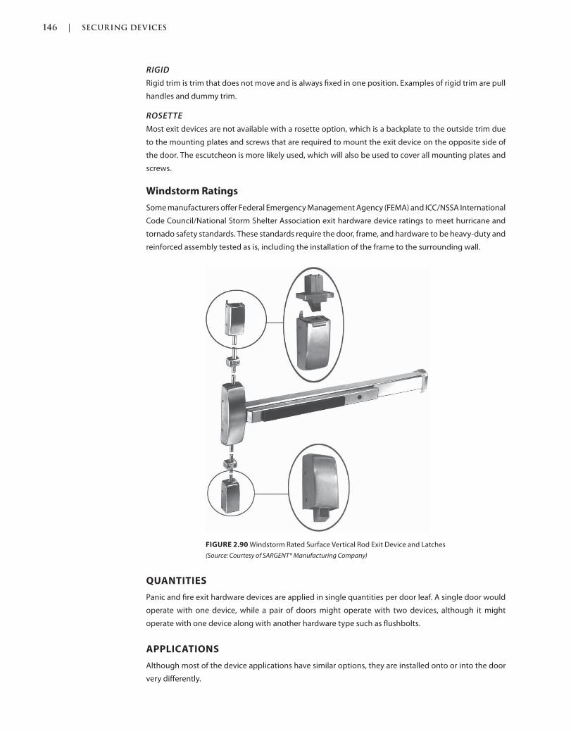
146 | SECURING DEVICES
c02.indd Page 146 03/03/2015 02:12:36:PM
RIGID
Rigid trim is trim that does not move and is always fixed in one position. Examples of rigid trim are pull
handles and dummy trim.
ROSETTE
Most exit devices are not available with a rosette option, which is a backplate to the outside trim due
to the mounting plates and screws that are required to mount the exit device on the opposite side of
the door. The escutcheon is more likely used, which will also be used to cover all mounting plates and
screws.
Windstorm Ratings
Some manufacturers offer Federal Emergency Management Agency (FEMA) and ICC/NSSA International
Code Council/National Storm Shelter Association exit hardware device ratings to meet hurricane and
tornado safety standards. These standards require the door, frame, and hardware to be heavy-duty and
reinforced assembly tested as is, including the installation of the frame to the surrounding wall.
FIGURE 2.90 Windstorm Rated Surface Vertical Rod Exit Device and Latches
(Source: Courtesy of SARGENT® Manufacturing Company)
QUANTITIES
Panic and fire exit hardware devices are applied in single quantities per door leaf. A single door would
operate with one device, while a pair of doors might operate with two devices, although it might
operate with one device along with another hardware type such as flushbolts.
APPLICATIONS
Although most of the device applications have similar options, they are installed onto or into the door
very differently.
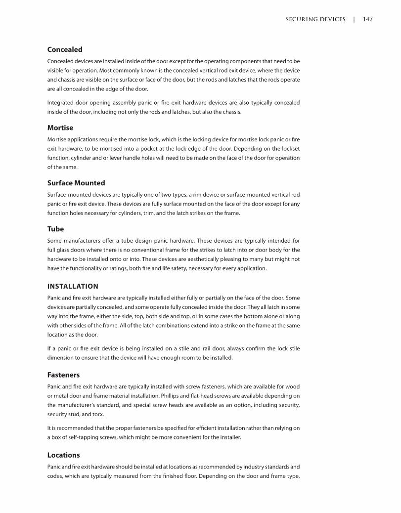
SECURING DEVICES | 147
c02.indd Page 147 03/03/2015 02:12:36:PM
Concealed
Concealed devices are installed inside of the door except for the operating components that need to be
visible for operation. Most commonly known is the concealed vertical rod exit device, where the device
and chassis are visible on the surface or face of the door, but the rods and latches that the rods operate
are all concealed in the edge of the door.
Integrated door opening assembly panic or fire exit hardware devices are also typically concealed
inside of the door, including not only the rods and latches, but also the chassis.
Mortise
Mortise applications require the mortise lock, which is the locking device for mortise lock panic or fire
exit hardware, to be mortised into a pocket at the lock edge of the door. Depending on the lockset
function, cylinder and or lever handle holes will need to be made on the face of the door for operation
of the same.
Surface Mounted
Surface-mounted devices are typically one of two types, a rim device or surface-mounted vertical rod
panic or fire exit device. These devices are fully surface mounted on the face of the door except for any
function holes necessary for cylinders, trim, and the latch strikes on the frame.
Tube
Some manufacturers offer a tube design panic hardware. These devices are typically intended for
full glass doors where there is no conventional frame for the strikes to latch into or door body for the
hardware to be installed onto or into. These devices are aesthetically pleasing to many but might not
have the functionality or ratings, both fire and life safety, necessary for every application.
INSTALLATION
Panic and fire exit hardware are typically installed either fully or partially on the face of the door. Some
devices are partially concealed, and some operate fully concealed inside the door. They all latch in some
way into the frame, either the side, top, both side and top, or in some cases the bottom alone or along
with other sides of the frame. All of the latch combinations extend into a strike on the frame at the same
location as the door.
If a panic or fire exit device is being installed on a stile and rail door, always confirm the lock stile
dimension to ensure that the device will have enough room to be installed.
Fasteners
Panic and fire exit hardware are typically installed with screw fasteners, which are available for wood
or metal door and frame material installation. Phillips and flat-head screws are available depending on
the manufacturer’s standard, and special screw heads are available as an option, including security,
security stud, and torx.
It is recommended that the proper fasteners be specified for efficient installation rather than relying on
a box of self-tapping screws, which might be more convenient for the installer.
Locations
Panic and fire exit hardware should be installed at locations as recommended by industry standards and
codes, which are typically measured from the finished floor. Depending on the door and frame type,
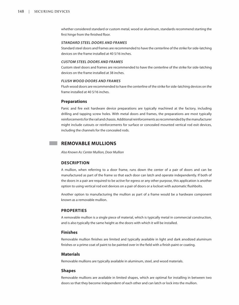
148 | SECURING DEVICES
c02.indd Page 148 03/03/2015 02:12:36:PM
whether considered standard or custom metal, wood or aluminum, standards recommend starting the
first hinge from the finished floor.
STANDARD STEEL DOORS AND FRAMES
Standard steel doors and frames are recommended to have the centerline of the strike for side-latching
devices on the frame installed at 40 5/16 inches.
CUSTOM STEEL DOORS AND FRAMES
Custom steel doors and frames are recommended to have the centerline of the strike for side-latching
devices on the frame installed at 38 inches.
FLUSH WOOD DOORS AND FRAMES
Flush wood doors are recommended to have the centerline of the strike for side-latching devices on the
frame installed at 40 5/16 inches.
Preparations
Panic and fire exit hardware device preparations are typically machined at the factory, including
drilling and tapping screw holes. With metal doors and frames, the preparations are most typically
reinforcements for the rail and chassis. Additional reinforcements as recommended by the manufacturer
might include cutouts or reinforcements for surface or concealed mounted vertical rod exit devices,
including the channels for the concealed rods.
REMOVABLE MULLIONS
Also Known As: Center Mullion, Door Mullion
DESCRIPTION
A mullion, when referring to a door frame, runs down the center of a pair of doors and can be
manufactured as part of the frame so that each door can latch and operate independently. If both of
the doors in a pair are required to be active for egress or any other purpose, this application is another
option to using vertical rod exit devices on a pair of doors or a lockset with automatic flushbolts.
Another option to manufacturing the mullion as part of a frame would be a hardware component
known as a removable mullion.
PROPERTIES
A removable mullion is a single piece of material, which is typically metal in commercial construction,
and is also typically the same height as the doors with which it will be installed.
Finishes
Removable mullion finishes are limited and typically available in light and dark anodized aluminum
finishes or a prime coat of paint to be painted over in the field with a finish paint or coating.
Materials
Removable mullions are typically available in aluminum, steel, and wood materials.
Shapes
Removable mullions are available in limited shapes, which are optimal for installing in between two
doors so that they become independent of each other and can latch or lock into the mullion.
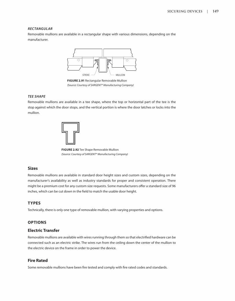
SECURING DEVICES | 149
c02.indd Page 149 03/03/2015 02:12:36:PM
RECTANGULAR
Removable mullions are available in a rectangular shape with various dimensions, depending on the
manufacturer.
FIGURE 2.91 Rectangular Removable Mullion
(Source: Courtesy of SARGENT® Manufacturing Company)
TEE SHAPE
Removable mullions are available in a tee shape, where the top or horizontal part of the tee is the
stop against which the door stops, and the vertical portion is where the door latches or locks into the
mullion.
FIGURE 2.92 Tee Shape Removable Mullion
(Source: Courtesy of SARGENT® Manufacturing Company)
Sizes
Removable mullions are available in standard door height sizes and custom sizes, depending on the
manufacturer’s availability as well as industry standards for proper and consistent operation. There
might be a premium cost for any custom size requests. Some manufacturers offer a standard size of 96
inches, which can be cut down in the field to match the usable door height.
TYPES
Technically, there is only one type of removable mullion, with varying properties and options.
OPTIONS
Electric Transfer
Removable mullions are available with wires running through them so that electrified hardware can be
connected such as an electric strike. The wires run from the ceiling down the center of the mullion to
the electric device on the frame in order to power the device.
Fire Rated
Some removable mullions have been fire tested and comply with fire rated codes and standards.
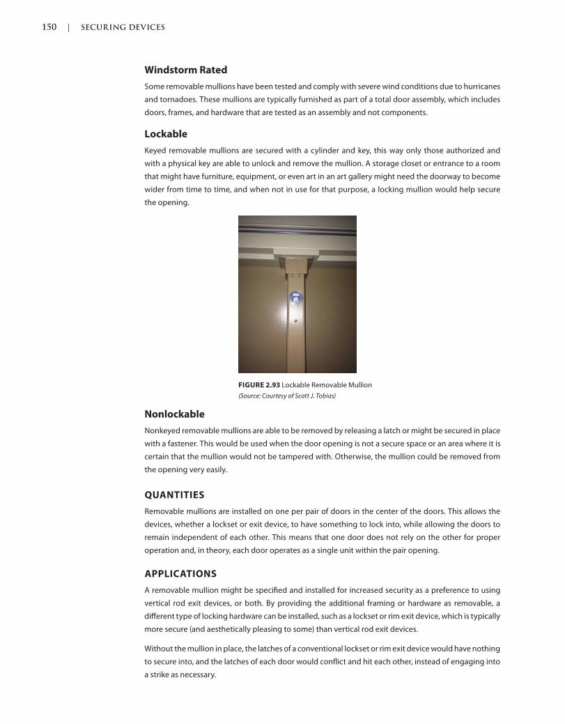
150 | SECURING DEVICES
c02.indd Page 150 03/03/2015 02:12:36:PM
Windstorm Rated
Some removable mullions have been tested and comply with severe wind conditions due to hurricanes
and tornadoes. These mullions are typically furnished as part of a total door assembly, which includes
doors, frames, and hardware that are tested as an assembly and not components.
Lockable
Keyed removable mullions are secured with a cylinder and key, this way only those authorized and
with a physical key are able to unlock and remove the mullion. A storage closet or entrance to a room
that might have furniture, equipment, or even art in an art gallery might need the doorway to become
wider from time to time, and when not in use for that purpose, a locking mullion would help secure
the opening.
FIGURE 2.93 Lockable Removable Mullion
(Source: Courtesy of Scott J. Tobias)
Nonlockable
Nonkeyed removable mullions are able to be removed by releasing a latch or might be secured in place
with a fastener. This would be used when the door opening is not a secure space or an area where it is
certain that the mullion would not be tampered with. Otherwise, the mullion could be removed from
the opening very easily.
QUANTITIES
Removable mullions are installed on one per pair of doors in the center of the doors. This allows the
devices, whether a lockset or exit device, to have something to lock into, while allowing the doors to
remain independent of each other. This means that one door does not rely on the other for proper
operation and, in theory, each door operates as a single unit within the pair opening.
APPLICATIONS
A removable mullion might be specified and installed for increased security as a preference to using
vertical rod exit devices, or both. By providing the additional framing or hardware as removable, a
different type of locking hardware can be installed, such as a lockset or rim exit device, which is typically
more secure (and aesthetically pleasing to some) than vertical rod exit devices.
Without the mullion in place, the latches of a conventional lockset or rim exit device would have nothing
to secure into, and the latches of each door would conflict and hit each other, instead of engaging into
a strike as necessary.
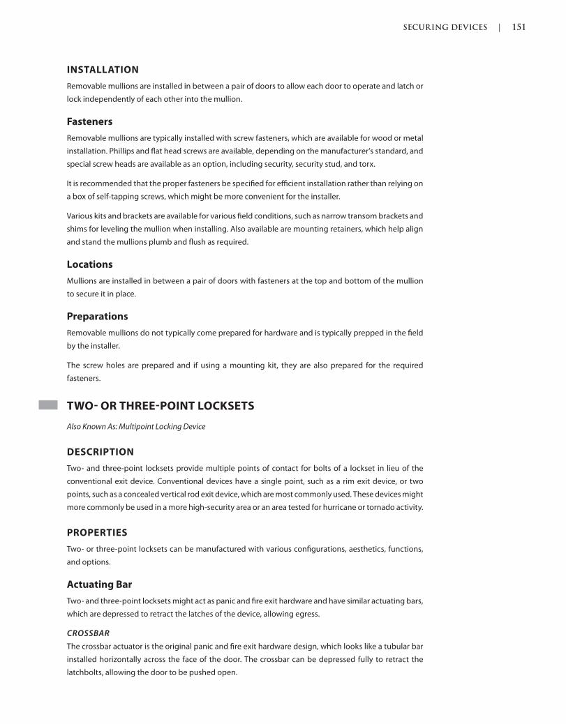
SECURING DEVICES | 151
c02.indd Page 151 03/03/2015 02:12:36:PM
INSTALLATION
Removable mullions are installed in between a pair of doors to allow each door to operate and latch or
lock independently of each other into the mullion.
Fasteners
Removable mullions are typically installed with screw fasteners, which are available for wood or metal
installation. Phillips and flat head screws are available, depending on the manufacturer’s standard, and
special screw heads are available as an option, including security, security stud, and torx.
It is recommended that the proper fasteners be specified for efficient installation rather than relying on
a box of self-tapping screws, which might be more convenient for the installer.
Various kits and brackets are available for various field conditions, such as narrow transom brackets and
shims for leveling the mullion when installing. Also available are mounting retainers, which help align
and stand the mullions plumb and flush as required.
Locations
Mullions are installed in between a pair of doors with fasteners at the top and bottom of the mullion
to secure it in place.
Preparations
Removable mullions do not typically come prepared for hardware and is typically prepped in the field
by the installer.
The screw holes are prepared and if using a mounting kit, they are also prepared for the required
fasteners.
TWO OR THREEPOINT LOCKSETS
Also Known As: Multipoint Locking Device
DESCRIPTION
Two- and three-point locksets provide multiple points of contact for bolts of a lockset in lieu of the
conventional exit device. Conventional devices have a single point, such as a rim exit device, or two
points, such as a concealed vertical rod exit device, which are most commonly used. These devices might
more commonly be used in a more high-security area or an area tested for hurricane or tornado activity.
PROPERTIES
Two- or three-point locksets can be manufactured with various configurations, aesthetics, functions,
and options.
Actuating Bar
Two- and three-point locksets might act as panic and fire exit hardware and have similar actuating bars,
which are depressed to retract the latches of the device, allowing egress.
CROSSBAR
The crossbar actuator is the original panic and fire exit hardware design, which looks like a tubular bar
installed horizontally across the face of the door. The crossbar can be depressed fully to retract the
latchbolts, allowing the door to be pushed open.
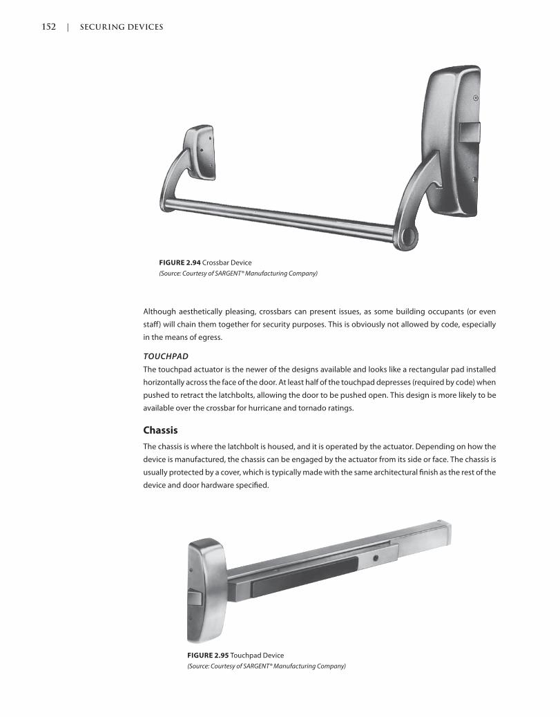
152 | SECURING DEVICES
c02.indd Page 152 03/03/2015 02:12:36:PM
Although aesthetically pleasing, crossbars can present issues, as some building occupants (or even
staff) will chain them together for security purposes. This is obviously not allowed by code, especially
in the means of egress.
TOUCHPAD
The touchpad actuator is the newer of the designs available and looks like a rectangular pad installed
horizontally across the face of the door. At least half of the touchpad depresses (required by code) when
pushed to retract the latchbolts, allowing the door to be pushed open. This design is more likely to be
available over the crossbar for hurricane and tornado ratings.
Chassis
The chassis is where the latchbolt is housed, and it is operated by the actuator. Depending on how the
device is manufactured, the chassis can be engaged by the actuator from its side or face. The chassis is
usually protected by a cover, which is typically made with the same architectural finish as the rest of the
device and door hardware specified.
FIGURE 2.94 Crossbar Device
(Source: Courtesy of SARGENT® Manufacturing Company)
FIGURE 2.95 Touchpad Device
(Source: Courtesy of SARGENT® Manufacturing Company)

SECURING DEVICES | 153
c02.indd Page 153 03/03/2015 02:12:36:PM
Finishes
Visible parts of an exit device are available in most architectural finishes, depending on the manufacturer
and their available selections.
Grade
Two- and three-point locksets are available in different grades known as grade 1, grade 2, and grade 3
with grade 1 being the best and highest grade. Aside from the grades, other ratings such as windstorm
for hurricane or no ratings for residential use might be available.
Materials
Two- and three-point lockset parts, including internal working parts, actuating bars, chassis, trim,
rods, and strikes, can be manufactured from brass, bronze, stainless steel, or steel, depending on the
manufacturer and device.
Strikes
Strikes are the keeper for latches of two- and three-point lockset hardware. Depending on the device
and latch type, there are strikes available to suit each, which are typically furnished with the device
along with fasteners and other required parts.
TYPES
Two Point
CONCEALED VERTICAL TOP AND BOTTOM RODS
Typically manufactured as a panic or fire exit hardware device, two-point locksets are available as con-
cealed vertical rods with a push rail on the egress side with two latches, one at the side and one at the
top, one at the top and bottom, or one at the side and one at the bottom. Concealed rods are similar
to surface ones, except the rods are hidden inside of the door opening. This helps with the aesthetics
for those who do not find surface-mounted rods appealing. However, like surface-mounted rods, this
hardware can be a maintenance nightmare because adjustment typically cannot be completed while
the door is hanging in the opening. The door will have to be taken down from its hanging device; the
latches will have to be adjusted regularly, depending on the frequency of use, and the door rehung
accordingly.
FIGURE 2.96 Concealed Two-Point Lockset
(Source: Courtesy of SARGENT® Manufacturing Company)
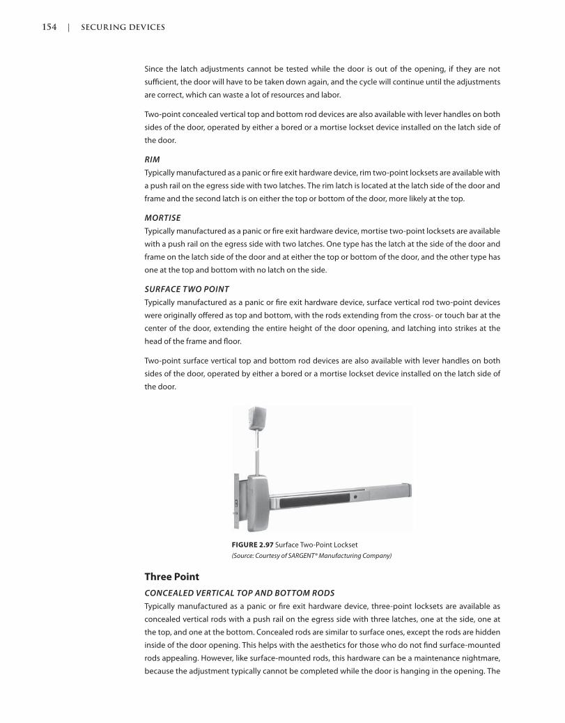
154 | SECURING DEVICES
c02.indd Page 154 03/03/2015 02:12:36:PM
Since the latch adjustments cannot be tested while the door is out of the opening, if they are not
sufficient, the door will have to be taken down again, and the cycle will continue until the adjustments
are correct, which can waste a lot of resources and labor.
Two-point concealed vertical top and bottom rod devices are also available with lever handles on both
sides of the door, operated by either a bored or a mortise lockset device installed on the latch side of
the door.
RIM
Typically manufactured as a panic or fire exit hardware device, rim two-point locksets are available with
a push rail on the egress side with two latches. The rim latch is located at the latch side of the door and
frame and the second latch is on either the top or bottom of the door, more likely at the top.
MORTISE
Typically manufactured as a panic or fire exit hardware device, mortise two-point locksets are available
with a push rail on the egress side with two latches. One type has the latch at the side of the door and
frame on the latch side of the door and at either the top or bottom of the door, and the other type has
one at the top and bottom with no latch on the side.
SURFACE TWO POINT
Typically manufactured as a panic or fire exit hardware device, surface vertical rod two-point devices
were originally offered as top and bottom, with the rods extending from the cross- or touch bar at the
center of the door, extending the entire height of the door opening, and latching into strikes at the
head of the frame and floor.
Two-point surface vertical top and bottom rod devices are also available with lever handles on both
sides of the door, operated by either a bored or a mortise lockset device installed on the latch side of
the door.
FIGURE 2.97 Surface Two-Point Lockset
(Source: Courtesy of SARGENT® Manufacturing Company)
Three Point
CONCEALED VERTICAL TOP AND BOTTOM RODS
Typically manufactured as a panic or fire exit hardware device, three-point locksets are available as
concealed vertical rods with a push rail on the egress side with three latches, one at the side, one at
the top, and one at the bottom. Concealed rods are similar to surface ones, except the rods are hidden
inside of the door opening. This helps with the aesthetics for those who do not find surface-mounted
rods appealing. However, like surface-mounted rods, this hardware can be a maintenance nightmare,
because the adjustment typically cannot be completed while the door is hanging in the opening. The
SECURING DEVICES | 155
c02.indd Page 155 03/03/2015 02:12:36:PM
door will have to be taken down from its hanging device; the latches will have to be adjusted regularly,
depending on the frequency of use, and the door rehung accordingly.
Since the latch adjustments cannot be tested while the door is out of the opening, if they are not
sufficient, the door will have to be taken down again, and the cycle will continue until the adjustments
are correct, which can waste a lot of resources and labor.
Concealed vertical top and bottom rod devices are also available with lever handles on both sides of
the door, operated by either a bored or mortise lockset device installed on the latch side of the door.
RIM
Typically manufactured as a panic or fire exit hardware device, rim three-point locksets are available
with a push rail on the egress side with three latches. The rim latch is located at the latch side of the door
and frame and the second and third latches at the top and bottom of the door.
MORTISE
Typically manufactured as a panic or fire exit hardware device, mortise three-point locksets are available
with a push rail on the egress side with three latches. One type has the latch at the side of the door and
frame on the latch side of the door and at either the top or bottom of the door, and the other type has
one at the top and bottom in addition to the mortise latch on the side.
SURFACE VERTICAL TOP AND BOTTOM RODS
Typically manufactured as a panic or fire exit hardware device, surface vertical rod three-point locksets
were originally offered as top and bottom, with the rods extending from the cross or touch bar at the
center of the door, extending the entire height of the door opening, and latching into strikes at the
head of the frame and floor in addition to the side.
Surface vertical top and bottom rod devices are also available with lever handles on both sides of the
door, either operated by a bored or a mortise lockset device installed on the latch side of the door.
OPTIONS
Anti-Microbial Coating
Two- or three-point locksets are available with an optional anti-microbial coating. The coating is a silver
ion–based clear coating that helps stop the spread of bacteria. Although there are silver ions, they are
not visible to the eye and a brass or bronze finish shows its true color through the coating. Silver has
been used throughout history to help reduce the spread of bacteria and infection: Why not put it on
doors and hardware that are touched over and over again by numerous different people in a day?
Auxiliary Control
An auxiliary control is an option to lock and unlock the door from the outside, or pull side of the door,
with a key and thumb turn where there are no lever handles or pulls but access might be required or
desired. The cylinder unlocks the thumb turn and allows the rotation of the thumb, which retracts the
latches of the exit device. This type of device might be questioned for ADA compliance.
Connectors
Electronic hardware has historically been connected by twisting together wires, but now there are
plastic connectors that are prewired by the manufacturer so that their hardware will connect easily
by plugging the devices together. Such connections are available on hinges that connect to door
harnesses that carry power across the door to the locking device.
156 | SECURING DEVICES
c02.indd Page 156 03/03/2015 02:12:36:PM
Cylinders
Cylinders are used to operate the outside trim of the device. Please see Cylinders for Locking Devices
in this chapter.
Dogging
Dogging a device means the device is operated to the open or unlocked position, where all of the bolts
are retracted and locked in that position.
The locking can be specified to use either a keyed cylinder or hex or Allen wrench key. Obviously, the
keyed cylinder is the more controlled type of function so that only those who have access to the key can
perform the function; otherwise, anyone with the right size Allen wrench can do the same.
Why would we want to dog open a device? Let’s use a school as an example. When a typical school is
opened for the day, if not dogged in the open position, the two- or three-point lockset would cycle
over and over each time a student, teacher, or other personnel opened the door and went through the
opening, putting excess wear on the device and shortening its life cycle.
If the two- or three-point lockset is dogged in the open position in the morning by those
responsible, the device acts as a push/pull device, and the latches, springs, and operation of the
device are limited, saving the components from unnecessary wear and tear, extending the life cycle
of the two- or three-point lockset.
Consider the electronic dogging we discussed earlier; with the flip of a switch from a central location we
would save the time of a person or persons who otherwise have to go around the school perimeter to
manually dog and undog these devices at the start and end of each day, not to mention possibly saving
lives in an emergency lockdown situation.
Electrical
Depending on the manufacturer, two- or three-point locksets are available with electrical options.
These options can be used for a multitude of purposes, including tying into a fire alarm system so that
the lockset opens when there is an emergency and a firefighter can gain access without having to break
through the door opening.
Another reason for having an electrical function is to tie into an alarm/security or access control system.
These systems have the ability to monitor the latching and locking of the opening, and can signal the
security station if this is not functioning as required. Access control simply means that one gains access
through the opening by presenting proper electronic credentials to the opening, which are confirmed
by the system.
DOGGING
Electric dogging is an option that allows dogging of the device by the use of an electrical force rather
than a mechanical one. Electric dogging can be accomplished by either physically depressing each
push pad so that it is held open electrically or by adding the option of electric latch retraction, which
allows retraction of the latch remotely to be electrically dogged by computer or a switch.
HARD WIRED
Hard-wired devices have wires running directly into them from an outside power source. The outside
power source can be a voltage source, such as 24 VAC, or a power over Ethernet source through your
computer cables that connect your network to the Internet.
SECURING DEVICES | 157
c02.indd Page 157 03/03/2015 02:12:36:PM
INTEGRATED WIEGAND
Two- and three-point lockset trim is available with an integrated Wiegand card reader device. This
reader is proximity-type, where the card is presented within proximity of the reader and is read by radio
frequency rather than having to make the card physically contact the surface of the reader.
LATCHBOLT MONITORING
Latchbolt monitoring is an electrified option that allows the monitoring of the latchbolt position,
whether extended or retracted. This allows the signaling of any devices that have not extended and
secured into the strike so that it can be followed up with in person to rectify the situation.
LEVER MONITORING
Lever monitoring is an electrified option that allows the monitoring of the lever handle position,
whether rotated or in the rest position. This allows the signaling of any lever handle that is in the rotated
position, indicating that the latchbolt is likely retracted and not secure in the strike.
LATCH RETRACTION
Electric latch retraction allows the remote electronic retraction and extension of the hardware latchbolt.
The operation can be accomplished by computer, a switch, or electronic credentials such as a card
reader. When the signal is initiated, the latch of the device is retracted so that the door can be pulled or
pushed open without having to retract the push pad from the inside or rotate a lever from the outside
of a device.
REQUEST TO EXIT SWITCH
Request to exit switches are an electrified option available to shunt an alarm during an authorized exit.
If a door has a local or remote alarmed exit hardware device, door and frame signal switch, lever or
latchbolt monitoring switch, a request to exit switch sends a signal to the contact, alarm, or computer
stating that the doorway is being accessed from the exit side and that no credentials are required. This
shunts the alarm, allowing the person to go through without having to present electronic credentials.
TRIM
Electrified trim is available on the outside of an exit device door so that a door can be accessed from the
outside with the use of an electronic access control system. Typically rigid, when a switch such as a card
reader authorizes the credentials presented to it, the trim unlocks and is able to be rotated to retract
the latchbolt, pull the door forward, and gain entry to the space.
Fail Safe
Fail-safe door trim is available to tie into a fire alarm system. This trim only locks when power is
applied to the opening and unlocks when power is released. This function uses power all of the time,
but is necessary to meet the codes in certain situations if electrification is necessary at the opening.
The devices are manufactured differently, depending on the manufacturer and options, and can be
operated by solenoid or a motorized mechanism, which would retract and throw the bolt accordingly,
or simply allow the lever or knob to be rotated to retract the latch manually.
Fail Secure
Fail-secure door trim is available for locking and unlocking a device. This trim only unlocks when power
is applied to the opening and locks when power is released. This device uses less power than fail safe,
as the power is only used when necessary to open the device. The devices are manufactured differently,
depending on the manufacturer and options, and can be operated by solenoid or a motorized
mechanism, which would retract and throw the bolt accordingly, or simply allow the lever or knob to
be rotated to retract the latch manually.
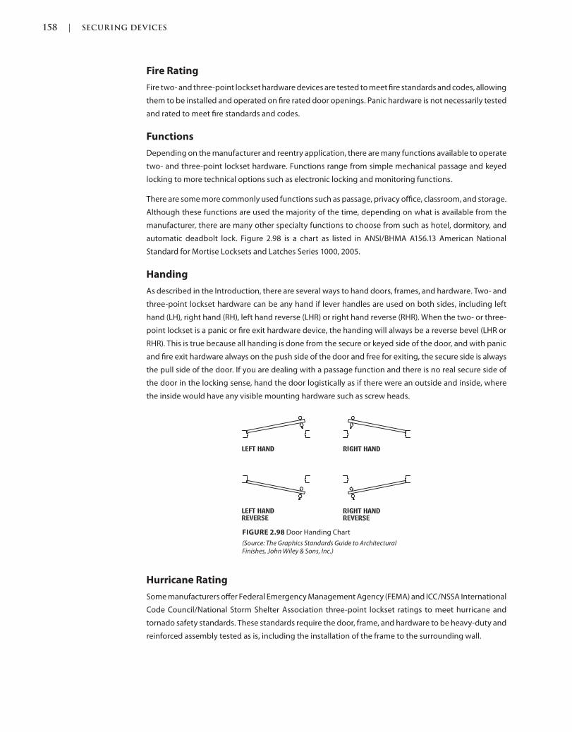
158 | SECURING DEVICES
c02.indd Page 158 03/03/2015 02:12:36:PM
Fire Rating
Fire two- and three-point lockset hardware devices are tested to meet fire standards and codes, allowing
them to be installed and operated on fire rated door openings. Panic hardware is not necessarily tested
and rated to meet fire standards and codes.
Functions
Depending on the manufacturer and reentry application, there are many functions available to operate
two- and three-point lockset hardware. Functions range from simple mechanical passage and keyed
locking to more technical options such as electronic locking and monitoring functions.
There are some more commonly used functions such as passage, privacy office, classroom, and storage.
Although these functions are used the majority of the time, depending on what is available from the
manufacturer, there are many other specialty functions to choose from such as hotel, dormitory, and
automatic deadbolt lock. Figure 2.98 is a chart as listed in ANSI/BHMA A156.13 American National
Standard for Mortise Locksets and Latches Series 1000, 2005.
Handing
As described in the Introduction, there are several ways to hand doors, frames, and hardware. Two- and
three-point lockset hardware can be any hand if lever handles are used on both sides, including left
hand (LH), right hand (RH), left hand reverse (LHR) or right hand reverse (RHR). When the two- or three-
point lockset is a panic or fire exit hardware device, the handing will always be a reverse bevel (LHR or
RHR). This is true because all handing is done from the secure or keyed side of the door, and with panic
and fire exit hardware always on the push side of the door and free for exiting, the secure side is always
the pull side of the door. If you are dealing with a passage function and there is no real secure side of
the door in the locking sense, hand the door logistically as if there were an outside and inside, where
the inside would have any visible mounting hardware such as screw heads.
FIGURE 2.98 Door Handing Chart
(Source: The Graphics Standards Guide to Architectural Finishes, John Wiley & Sons, Inc.)
Hurricane Rating
Some manufacturers offer Federal Emergency Management Agency (FEMA) and ICC/NSSA International
Code Council/National Storm Shelter Association three-point lockset ratings to meet hurricane and
tornado safety standards. These standards require the door, frame, and hardware to be heavy-duty and
reinforced assembly tested as is, including the installation of the frame to the surrounding wall.
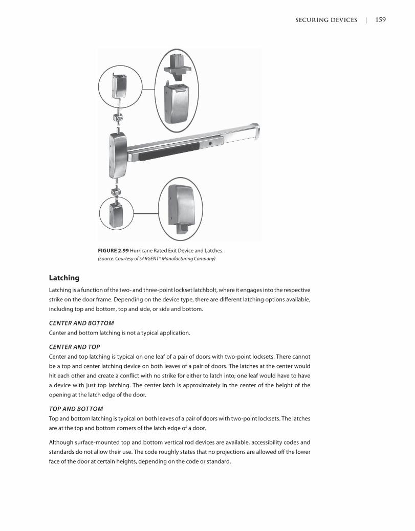
SECURING DEVICES | 159
c02.indd Page 159 03/03/2015 02:12:36:PM
Latching
Latching is a function of the two- and three-point lockset latchbolt, where it engages into the respective
strike on the door frame. Depending on the device type, there are different latching options available,
including top and bottom, top and side, or side and bottom.
CENTER AND BOTTOM
Center and bottom latching is not a typical application.
CENTER AND TOP
Center and top latching is typical on one leaf of a pair of doors with two-point locksets. There cannot
be a top and center latching device on both leaves of a pair of doors. The latches at the center would
hit each other and create a conflict with no strike for either to latch into; one leaf would have to have
a device with just top latching. The center latch is approximately in the center of the height of the
opening at the latch edge of the door.
TOP AND BOTTOM
Top and bottom latching is typical on both leaves of a pair of doors with two-point locksets. The latches
are at the top and bottom corners of the latch edge of a door.
Although surface-mounted top and bottom vertical rod devices are available, accessibility codes and
standards do not allow their use. The code roughly states that no projections are allowed off the lower
face of the door at certain heights, depending on the code or standard.
FIGURE 2.99 Hurricane Rated Exit Device and Latches.
(Source: Courtesy of SARGENT® Manufacturing Company)

160 | SECURING DEVICES
c02.indd Page 160 03/03/2015 02:12:36:PM
TOP, CENTER, AND BOTTOM
Top, center, and bottom latching is typical on one leaf of a pair of doors or a single door, possibly rated for
hurricanes or tornados, with three-point locksets. There cannot be a center latching device on both leaves
of a pair of doors as the latches at the center would hit each other and create a conflict with no strike for
either to latch into; one leaf would have to have a device with just top and or top and bottom latching.
The center latch is approximately in the center of the height of the opening at the latch edge of the
door and depending on the door type, anywhere from 38 inches to 40 5/16 inches above the finished
floor and the top latch is at the top corner or the latch edge of a door.
Although surface-mounted center, top, and bottom two- and three-point locksets are available,
accessibility codes and standards do not allow their use. The code roughly states that no projections
are allowed off the lower face of the door at certain heights depending on the code or standard.
Luminous
Although the use of luminous materials was minimal and voluntary several years ago, there are some
manufacturers that have manufactured these materials into their devices and are now prepared as they
become requirements. Devices without this option will have to have the luminous materials applied
to the device, as either a sticker or paint, neither of which are substantial and reliable materials for the
application.
Codes such as the International Building Code (IBC) are becoming more detailed, with the requirement
for luminous materials on panic and fire exit hardware on certain openings, which would include any
two- or three-point locksets tested for the same. Section 1024 of the IBC states, “Where a panic bar is
installed, such material shall be no less than 1 inch (25 mm) wide for the entire length of the actuating
bar or touchpad.”
ELECTRO
Electro-luminous material is a high-intensity light source that emits light through fire and smoke. This
light source requires power and would have to be tied into a backup generator to operate. Although
it is not part of the codes or standards that the luminous material be electric, there are manufacturers
that have this type of panic and fire exit device available.
FIGURE 2.100 Electro-Luminous Exit Device
(Source: Courtesy of SARGENT® Manufacturing Company)
PHOTO
Photo-luminous material is a glow-in-the-dark light source that emits light through fire and smoke.
This light source does not require power other than a separate light source shining on it to keep it
charged. The codes and standards are typically met with this type of luminous material, and there are
manufacturers that have this type of panic and fire exit device available.
Trim
Trim, also referred to as knobs, lever handles, or pulls, is available in many options and designs,
depending on the manufacturer. The lever, knob, and pull designs are typically mounted on an
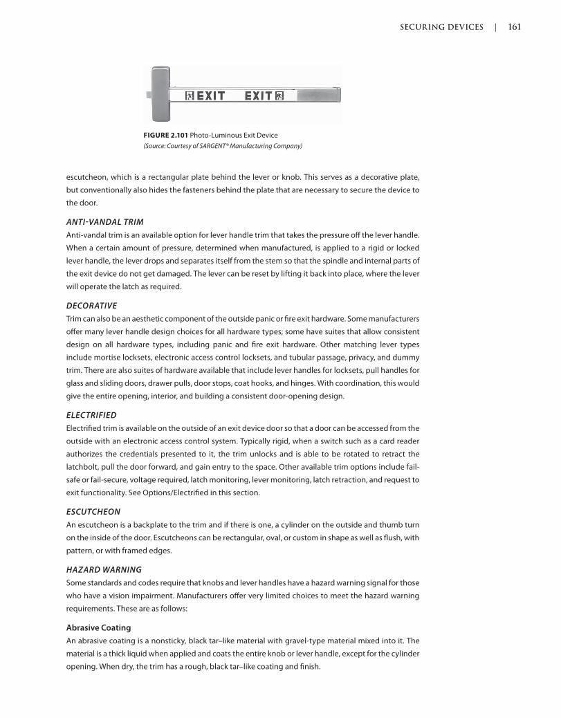
SECURING DEVICES | 161
c02.indd Page 161 03/03/2015 02:12:36:PM
escutcheon, which is a rectangular plate behind the lever or knob. This serves as a decorative plate,
but conventionally also hides the fasteners behind the plate that are necessary to secure the device to
the door.
ANTIVANDAL TRIM
Anti-vandal trim is an available option for lever handle trim that takes the pressure off the lever handle.
When a certain amount of pressure, determined when manufactured, is applied to a rigid or locked
lever handle, the lever drops and separates itself from the stem so that the spindle and internal parts of
the exit device do not get damaged. The lever can be reset by lifting it back into place, where the lever
will operate the latch as required.
DECORATIVE
Trim can also be an aesthetic component of the outside panic or fire exit hardware. Some manufacturers
offer many lever handle design choices for all hardware types; some have suites that allow consistent
design on all hardware types, including panic and fire exit hardware. Other matching lever types
include mortise locksets, electronic access control locksets, and tubular passage, privacy, and dummy
trim. There are also suites of hardware available that include lever handles for locksets, pull handles for
glass and sliding doors, drawer pulls, door stops, coat hooks, and hinges. With coordination, this would
give the entire opening, interior, and building a consistent door-opening design.
ELECTRIFIED
Electrified trim is available on the outside of an exit device door so that a door can be accessed from the
outside with an electronic access control system. Typically rigid, when a switch such as a card reader
authorizes the credentials presented to it, the trim unlocks and is able to be rotated to retract the
latchbolt, pull the door forward, and gain entry to the space. Other available trim options include fail-
safe or fail-secure, voltage required, latch monitoring, lever monitoring, latch retraction, and request to
exit functionality. See Options/Electrified in this section.
ESCUTCHEON
An escutcheon is a backplate to the trim and if there is one, a cylinder on the outside and thumb turn
on the inside of the door. Escutcheons can be rectangular, oval, or custom in shape as well as flush, with
pattern, or with framed edges.
HAZARD WARNING
Some standards and codes require that knobs and lever handles have a hazard warning signal for those
who have a vision impairment. Manufacturers offer very limited choices to meet the hazard warning
requirements. These are as follows:
Abrasive Coating
An abrasive coating is a nonsticky, black tar–like material with gravel-type material mixed into it. The
material is a thick liquid when applied and coats the entire knob or lever handle, except for the cylinder
opening. When dry, the trim has a rough, black tar–like coating and finish.
FIGURE 2.101 Photo-Luminous Exit Device
(Source: Courtesy of SARGENT® Manufacturing Company)
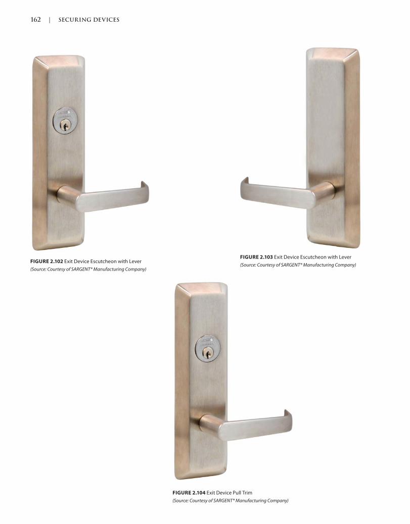
162 | SECURING DEVICES
c02.indd Page 162 03/03/2015 02:12:36:PM
FIGURE 2.104 Exit Device Pull Trim
(Source: Courtesy of SARGENT® Manufacturing Company)
FIGURE 2.102 Exit Device Escutcheon with Lever
(Source: Courtesy of SARGENT® Manufacturing Company)
FIGURE 2.103 Exit Device Escutcheon with Lever
(Source: Courtesy of SARGENT® Manufacturing Company)
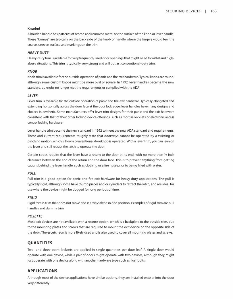
SECURING DEVICES | 163
c02.indd Page 163 03/03/2015 02:12:36:PM
Knurled
A knurled handle has patterns of scored and removed metal on the surface of the knob or lever handle.
These “bumps” are typically on the back side of the knob or handle where the fingers would feel the
coarse, uneven surface and markings on the trim.
HEAVY DUTY
Heavy-duty trim is available for very frequently used door openings that might need to withstand high-
abuse situations. This trim is typically very strong and will outlast conventional-duty trim.
KNOB
Knob trim is available for the outside operation of panic and fire exit hardware. Typical knobs are round,
although some custom knobs might be more oval or square. In 1992, lever handles became the new
standard, as knobs no longer met the requirements or complied with the ADA.
LEVER
Lever trim is available for the outside operation of panic and fire exit hardware. Typically elongated and
extending horizontally across the door face at the door lock edge, lever handles have many designs and
choices in aesthetic. Some manufacturers offer lever trim designs for their panic and fire exit hardware
consistent with that of their other locking device offerings, such as mortise locksets or electronic access
control locking hardware.
Lever handle trim became the new standard in 1992 to meet the new ADA standard and requirements.
These and current requirements roughly state that doorways cannot be operated by a twisting or
pinching motion, which is how a conventional doorknob is operated. With a lever trim, you can lean on
the lever and still retract the latch to operate the door.
Certain codes require that the lever have a return to the door at its end, with no more than ½-inch
clearance between the end of the return and the door face. This is to prevent anything from getting
caught behind the lever handle, such as clothing or a fire hose prior to being filled with water.
PULL
Pull trim is a good option for panic and fire exit hardware for heavy-duty applications. The pull is
typically rigid, although some have thumb pieces and or cylinders to retract the latch, and are ideal for
use where the device might be dogged for long periods of time.
RIGID
Rigid trim is trim that does not move and is always fixed in one position. Examples of rigid trim are pull
handles and dummy trim.
ROSETTE
Most exit devices are not available with a rosette option, which is a backplate to the outside trim, due
to the mounting plates and screws that are required to mount the exit device on the opposite side of
the door. The escutcheon is more likely used and is also used to cover all mounting plates and screws.
QUANTITIES
Two- and three-point locksets are applied in single quantities per door leaf. A single door would
operate with one device, while a pair of doors might operate with two devices, although they might
just operate with one device along with another hardware type such as flushbolts.
APPLICATIONS
Although most of the device applications have similar options, they are installed onto or into the door
very differently.
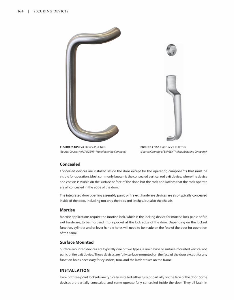
164 | SECURING DEVICES
c02.indd Page 164 03/03/2015 02:12:36:PM
Concealed
Concealed devices are installed inside the door except for the operating components that must be
visible for operation. Most commonly known is the concealed vertical rod exit device, where the device
and chassis is visible on the surface or face of the door, but the rods and latches that the rods operate
are all concealed in the edge of the door.
The integrated door opening assembly panic or fire exit hardware devices are also typically concealed
inside of the door, including not only the rods and latches, but also the chassis.
Mortise
Mortise applications require the mortise lock, which is the locking device for mortise lock panic or fire
exit hardware, to be mortised into a pocket at the lock edge of the door. Depending on the lockset
function, cylinder and or lever handle holes will need to be made on the face of the door for operation
of the same.
Surface Mounted
Surface-mounted devices are typically one of two types, a rim device or surface-mounted vertical rod
panic or fire exit device. These devices are fully surface-mounted on the face of the door except for any
function holes necessary for cylinders, trim, and the latch strikes on the frame.
INSTALLATION
Two- or three-point locksets are typically installed either fully or partially on the face of the door. Some
devices are partially concealed, and some operate fully concealed inside the door. They all latch in
FIGURE 2.105 Exit Device Pull Trim
(Source: Courtesy of SARGENT® Manufacturing Company)
FIGURE 2.106 Exit Device Pull Trim
(Source: Courtesy of SARGENT® Manufacturing Company)
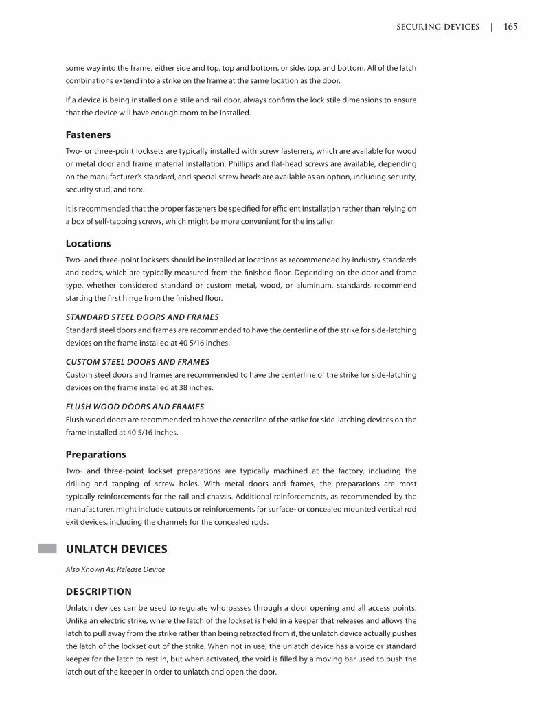
SECURING DEVICES | 165
c02.indd Page 165 03/03/2015 02:12:36:PM
some way into the frame, either side and top, top and bottom, or side, top, and bottom. All of the latch
combinations extend into a strike on the frame at the same location as the door.
If a device is being installed on a stile and rail door, always confirm the lock stile dimensions to ensure
that the device will have enough room to be installed.
Fasteners
Two- or three-point locksets are typically installed with screw fasteners, which are available for wood
or metal door and frame material installation. Phillips and flat-head screws are available, depending
on the manufacturer’s standard, and special screw heads are available as an option, including security,
security stud, and torx.
It is recommended that the proper fasteners be specified for efficient installation rather than relying on
a box of self-tapping screws, which might be more convenient for the installer.
Locations
Two- and three-point locksets should be installed at locations as recommended by industry standards
and codes, which are typically measured from the finished floor. Depending on the door and frame
type, whether considered standard or custom metal, wood, or aluminum, standards recommend
starting the first hinge from the finished floor.
STANDARD STEEL DOORS AND FRAMES
Standard steel doors and frames are recommended to have the centerline of the strike for side-latching
devices on the frame installed at 40 5/16 inches.
CUSTOM STEEL DOORS AND FRAMES
Custom steel doors and frames are recommended to have the centerline of the strike for side-latching
devices on the frame installed at 38 inches.
FLUSH WOOD DOORS AND FRAMES
Flush wood doors are recommended to have the centerline of the strike for side-latching devices on the
frame installed at 40 5/16 inches.
Preparations
Two- and three-point lockset preparations are typically machined at the factory, including the
drilling and tapping of screw holes. With metal doors and frames, the preparations are most
typically reinforcements for the rail and chassis. Additional reinforcements, as recommended by the
manufacturer, might include cutouts or reinforcements for surface- or concealed mounted vertical rod
exit devices, including the channels for the concealed rods.
UNLATCH DEVICES
Also Known As: Release Device
DESCRIPTION
Unlatch devices can be used to regulate who passes through a door opening and all access points.
Unlike an electric strike, where the latch of the lockset is held in a keeper that releases and allows the
latch to pull away from the strike rather than being retracted from it, the unlatch device actually pushes
the latch of the lockset out of the strike. When not in use, the unlatch device has a voice or standard
keeper for the latch to rest in, but when activated, the void is filled by a moving bar used to push the
latch out of the keeper in order to unlatch and open the door.
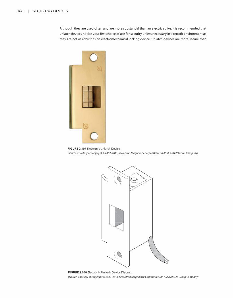
166 | SECURING DEVICES
c02.indd Page 166 03/03/2015 02:12:36:PM
Although they are used often and are more substantial than an electric strike, it is recommended that
unlatch devices not be your first choice of use for security unless necessary in a retrofit environment as
they are not as robust as an electromechanical locking device. Unlatch devices are more secure than
FIGURE 2.108 Electronic Unlatch Device Diagram
(Source: Courtesy of copyright © 2002–2013, Securitron Magnalock Corporation, an ASSA ABLOY Group Company)
FIGURE 2.107 Electronic Unlatch Device
(Source: Courtesy of copyright © 2002–2013, Securitron Magnalock Corporation, an ASSA ABLOY Group Company)
SECURING DEVICES | 167
c02.indd Page 167 03/03/2015 02:12:36:PM
electric strikes due to the one-piece construction, which allows the latch to rest inside of the strike like a
conventional strike plate and not rest behind a keeper that is held in place by pins and springs. Unlatch
devices are ideal for traffic control or for audit trail records of an opening.
PROPERTIES
Unlatch devices have a conventional strike plate keeper, which is where the latch of the locking device
engages. The strike keeper is fixed and, unlike an electric strike, pushes the latch of the locking device
out rather than releasing it from the front when operated.
Finishes
Unlatch devices are typically available in a limited number of the basic finishes, depending on the
manufacturer. The finish of the device is typically a cover plate that covers the exposed edge of the
unlatch device.
Grades
Unlatch devices are tested and graded with levels of 1, 2, and 3 by ANSI/BHMA with grade 1 being the
highest and best performing. The tests for the grade include cycle and strength tests.
Materials
Unlatch devices are typically manufactured from metal, plastic, and wire materials that operate inside
of a metal or plastic housing.
TYPES
Bored
Bored unlatch devices are available to suit bored or cylindrical type locksets. The unlatch device is
mortised into the strike frame jamb.
Mortise
Mortise unlatch devices are available to suit mortise locksets. The unlatch device is mortised into the
strike frame jamb. Some mortise unlatch devices are able to accept not only the latchbolt of the locking
device, but also the integrated deadbolt.
OPTIONS
Connectors
Electronic hardware has, historically, been connected by twisting together wires, but now there are
plastic connectors that are prewired by the manufacturer so that their hardware will connect easily
by plugging the devices together. Such connections are available on hinges that connect to door
harnesses that carry power across the door to the locking device.
Ampere (Amp)
An ampere (amp) is a measure of the amount of electric charge passing a point in an electric circuit. In
other words, it is the speed that the electricity travels through a device, wire, and system.
Current
Current requirements differ by manufacturer and device. Available as an alternating or direct current,
they must be correctly coordinated in order to have proper operation and function of electrical devices.
168 | SECURING DEVICES
c02.indd Page 168 03/03/2015 02:12:36:PM
ALTERNATING CURRENT AC
Alternating current (AC) is the typical power used in our homes and standard outlets. The current is
sent to and from the device in alternating directions. If you have ever noticed a buzzing sound at a door
with an electric strike when power is sent to it, you are likely hearing the alternating current running
through the device.
DIRECT CURRENT DC
Direct current (DC) can eliminate the buzzing sound and is a one-way current similar to that of a battery
and does not create a buzzing sound.
Extended Lip
Depending on the manufacturer, electric strikes are available with the option to extend the lip of the
strike. This would be necessary if the door were not flush with the edge of the door and inset into a
reveal in the frame. This would give the latch a plate to rub against as it swings in and out of the reveal
in the frame instead of possibly scraping against the frame’s paint or finish and possibly scratching it.
Fail Safe
Fail-safe strikes are available to tie into a fire alarm system. This trim only locks when power is applied
to the opening and unlocks when power is released. This function uses power all of the time, but is
necessary to meet the codes in certain situations if electrification is necessary at the opening. The
devices are manufactured differently, depending on the manufacturer and options, and can be
operated by solenoid or a motorized mechanism, which would retract and throw the bolt accordingly,
or simply allow the lever or knob to be rotated to retract the latch manually.
Fail Secure
Fail-secure strikes are available for locking and unlocking a device. This trim only unlocks when power
is applied to the opening and locks when power is released. This device uses less power than fail safe,
as the power is only used when necessary to open the device. The devices are manufactured differently,
depending on the manufacturer and options, and can be operated by solenoid or a motorized
mechanism, which would retract and throw the bolt accordingly, or simply allow the lever or knob to
be rotated to retract the latch manually.
Voltage
Voltage requirements differ by manufacturer and device. Available with various voltages, such as
12 VAC or DC, and 24 VAC or DC, they must be coordinated properly in order to have proper operation
and function of electrical devices. With that said, there are manufacturers that have devices that operate
with multiple voltages, so one does not need to coordinate them when purchasing the devices, but you
should do so when installing them to be certain there are no errors and the devices are not ruined and
left unusable.
QUANTITIES
Unlatch devices are installed in single quantities of one device per latch.
APPLICATIONS
Mortise
Unlatch devices are mortised into the strike frame jamb, where power is run to the device, typically
down the jamb from the ceiling above, where it is typically connected to a building’s power supply.

SECURING DEVICES | 169
c02.indd Page 169 03/03/2015 02:12:36:PM
INSTALLATION
An unlatch device is typically installed on the frame or on the inactive leaf of a pair of doors, and the
latchbolt and or deadbolt of the locking device is secured in the keeper of the strike. The latchbolt
of the locking device is pushed through the strike and keeper of the unlatch device once the strike is
released, not requiring the latchbolt to be retracted by the handle or knob as with mechanical strikes.
If an unlatch device is being installed on a stile and rail door, always confirm the lock stile’s dimension
to ensure that the device will have enough room to be installed.
Fasteners
Unlatch devices are typically installed with screw fasteners, which are available for wood or
metal door and frame material. Phillips and flat-head screws are available, depending on the
manufacturer’s standard, and special screw heads are available as an option, including security,
security stud, and torx.
It is recommended that the proper fasteners be specified for efficient installation rather than relying on
a box of self-tapping screws, which might be more convenient for the installer.
Locations
Unlatch devices should be installed at locations as recommended by industry standards and codes,
which are typically measured from the finished floor. Depending on the door and frame type, whether
they are considered standard or custom metal, wood, or aluminum, standards recommend starting the
first hinge from the finished floor.
STANDARD STEEL DOORS AND FRAMES
Standard steel doors and frames are recommended to have the centerline of the strike on the frame
installed at 40 5/16 inches.
CUSTOM STEEL DOORS AND FRAMES
Custom steel doors and frames are recommended to have the centerline of the strike on the frame
installed at 38 inches.
FLUSH WOOD DOORS AND FRAMES
Flush wood doors are recommended to have the strike on the frame installed at 40 5/16 inches.
Preparations
Unlatch device preparations are typically machined at the factory, including the drilling and tapping of
screw holes. With metal doors and frames, the preparation is typically a cutout in the location where an
unlatch device will be installed.
ELECTROMAGNETIC LOCKSETS
Also Known As: Electromagnets, Magnetic Locks, Magnetic Locksets, Magnetic Locking Device
DESCRIPTION
Electromagnetic locksets were one of the first types of electrified locking devices, and although
there are many new devices and technologies available, electromagnetic locksets are still used today.
They are typically used on retrofit applications on existing doors and on stile and rail, full glass doors
requiring minimal modification to the door, frame, and surrounding conditions as a way to add security
170 | SECURING DEVICES
c02.indd Page 170 03/03/2015 02:12:36:PM
and locking power, and to regulate who passes through a doorway or access point, by the use of a
release device such as a card reader or keypad.
As with many codes and standards, through experience and time, these have changed through the
years and language has been added to specifically address electromagnetic locksets, some prohibiting
their use altogether.
Since electricity is required to power the magnet, all electromagnetic locks are fail-safe and will release
and allow the door to be opened unless equipped with a backup power supply. Electromagnetic locks
operate on DC power and, unlike electric strikes, are silent when locked or unlocked.
PROPERTIES
In addition to the wiring and electronic components inside of the device, there are two parts to an
electromagnetic lockset, the magnetic lock body and an armature, both of which can be installed on
the door or frame, depending on the application and available options from the manufacturer.
Armature
The armature is typically installed on the door and is the component that the electromagnetic lock
aligns and secures with in order to lock the opening. The electromagnetic lock obviously needs
electricity to operate, and the armature is basically a piece of metal that requires no power, which is
likely why it is installed on the door, since the power originates from the wall and has to be transferred
to the door through a transfer device. It is typically more secure and easier to install, and there are fewer
possibilities for something to go wrong if the electromagnetic lock is installed on the door frame, which
is easily connected to the power in the wall or ceiling above.
Body
The body is powered by electricity, which creates a very strong magnetic force that secures the door
and frame by holding them together. If the electricity or power to the device is lost, the electromagnet
will release from the armature, allowing the door to open. When it is in operation, release is achieved by
switching off power to the magnet by the use of a release device, which is typically wired or tied into the
electronic access control and security system. Release device options are a pushbutton switch, motion
detectors, and biometric devices, which read unique characteristics of people such as fingerprints, the
retina of the eye, vein patterns of the wrist, and the entire face.
Finishes
Typically available in the same finish as the body material used to manufacture the electromagnetic lockset,
satin stainless steel, anodized aluminum finishes, satin aluminum, black, and brown are most common. A
version primed for painting is also available, and some manufacturers offer cover plates, also known as dress
covers, that allow customary and consistent finishes similar to the balance of the installed door hardware.
Grades
According to ANSI/BHMA A156.23 American National Standard for Electromagnetic Locks, 2012,
electromagnetic locksets should meet the minimum testing standards. These testing standards include
cycle and operational tests requiring minimum cycles of 250,000 for grade 3; 500,000 for grade 2; and
1,000,000 for grade 1.
Materials
Depending on the grade, quality, and manufacturer, electromagnetic lockset bodies can be
manufactured from a steel (more commonly stainless steel) or aluminum material. The armature is
SECURING DEVICES | 171
c02.indd Page 171 03/03/2015 02:12:36:PM
typically manufactured from a steel material with through-bolts attached to the armature plate, which
are used to attach the armature plate to the door.
TYPES
There is really only one type of electromagnetic lockset, where the body is powered by electricity and
“locks” or adheres via electromagnet to the armature. The differences in the types of electromagnetic
locksets are more in the various applications and options from the various manufacturers.
OPTIONS
Automatic Relock Timer
Once the power is removed from and unlocks the device, an automatic relock timer allows an
electromagnetic lock to reset itself, power back up, and be ready to secure the opening again. The
timer is typically adjustable and can be set anywhere from 0 to 30 seconds.
Brackets
Various brackets are available to suit common and unique door and frame applications and surrounding
conditions.
ALUMINUM SHIM
An aluminum shim bracket is available to lift the electromagnetic lockset off the surface to accommodate
installations, typically existing, that are not flush.
HEADER
As with all hardware that is installed into a frame cavity, a header bracket is available to give additional
reinforcement to the shear lock or concealed electromagnetic lockset installations to give the hardware
a more substantial installation into the void in the frame.
WOOD DOOR
As with all hardware that is installed into a door cavity, reinforcement brackets are available for wood
door shear lock or concealed electromagnetic lockset installations to give the hardware a more
substantial installation into the void in the door. This helps prevent the face, or veneer, of the door from
being damaged or removed in part or altogether during installation or stressful use of the opening.
ZBRACKET
Named Z-brackets due to their shape, these hardware pieces are available for in-swinging door
installations. As with most door hardware, we try to keep anything that can be tampered with on the
secure (or inside) of the opening. On a typical out-swinging door, the electromagnetic lock is installed
on the push side of the door on the head of the frame. On in-swinging doors the stop of the frame is
in the way, and in order to accommodate an armature alignment for locking, the Z-bracket is installed.
Camera
As the typical use of an electromagnetic lockset is to regulate who passes through a doorway or access
point, by the use of a release device such as a card reader or keypad, and in order to consolidate devices
and reduce the wiring requirements to an opening, some manufacturers have manufactured security
cameras into their electromagnetic locksets as an added feature.
Clamps
Clamps are an option that secures the electromagnetic lockset with more than just electricity. In
addition to the magnetic power, clamps affixed to the body latch onto the armature, holding it in place,
increasing the holding force by thousands of additional pounds.
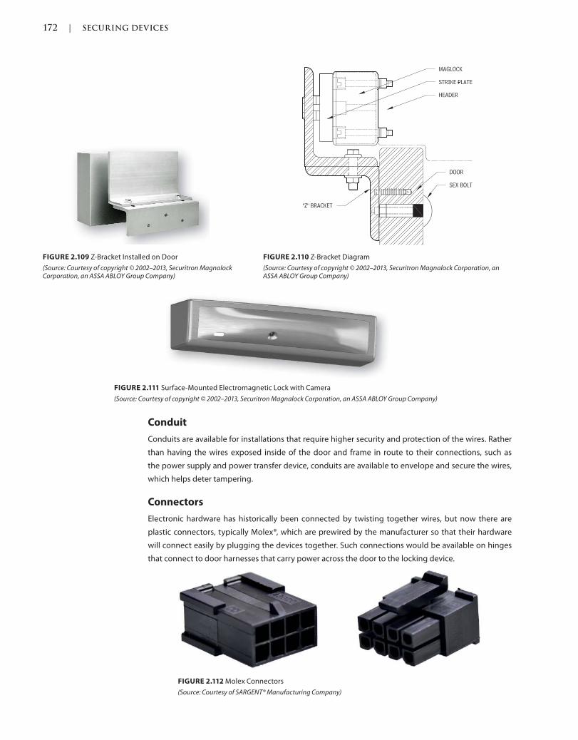
172 | SECURING DEVICES
c02.indd Page 172 03/03/2015 02:12:36:PM
Conduit
Conduits are available for installations that require higher security and protection of the wires. Rather
than having the wires exposed inside of the door and frame in route to their connections, such as
the power supply and power transfer device, conduits are available to envelope and secure the wires,
which helps deter tampering.
Connectors
Electronic hardware has historically been connected by twisting together wires, but now there are
plastic connectors, typically Molex®, which are prewired by the manufacturer so that their hardware
will connect easily by plugging the devices together. Such connections would be available on hinges
that connect to door harnesses that carry power across the door to the locking device.
FIGURE 2.109 Z-Bracket Installed on Door
(Source: Courtesy of copyright © 2002–2013, Securitron Magnalock Corporation, an ASSA ABLOY Group Company)
FIGURE 2.110 Z-Bracket Diagram
(Source: Courtesy of copyright © 2002–2013, Securitron Magnalock Corporation, an ASSA ABLOY Group Company)
FIGURE 2.111 Surface-Mounted Electromagnetic Lock with Camera
(Source: Courtesy of copyright © 2002–2013, Securitron Magnalock Corporation, an ASSA ABLOY Group Company)
FIGURE 2.112 Molex Connectors
(Source: Courtesy of SARGENT® Manufacturing Company)
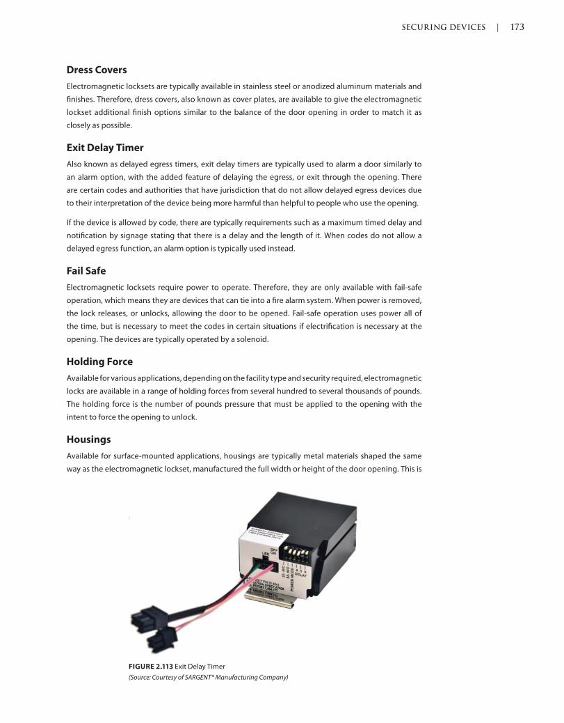
SECURING DEVICES | 173
c02.indd Page 173 03/03/2015 02:12:36:PM
Dress Covers
Electromagnetic locksets are typically available in stainless steel or anodized aluminum materials and
finishes. Therefore, dress covers, also known as cover plates, are available to give the electromagnetic
lockset additional finish options similar to the balance of the door opening in order to match it as
closely as possible.
Exit Delay Timer
Also known as delayed egress timers, exit delay timers are typically used to alarm a door similarly to
an alarm option, with the added feature of delaying the egress, or exit through the opening. There
are certain codes and authorities that have jurisdiction that do not allow delayed egress devices due
to their interpretation of the device being more harmful than helpful to people who use the opening.
If the device is allowed by code, there are typically requirements such as a maximum timed delay and
notification by signage stating that there is a delay and the length of it. When codes do not allow a
delayed egress function, an alarm option is typically used instead.
Fail Safe
Electromagnetic locksets require power to operate. Therefore, they are only available with fail-safe
operation, which means they are devices that can tie into a fire alarm system. When power is removed,
the lock releases, or unlocks, allowing the door to be opened. Fail-safe operation uses power all of
the time, but is necessary to meet the codes in certain situations if electrification is necessary at the
opening. The devices are typically operated by a solenoid.
Holding Force
Available for various applications, depending on the facility type and security required, electromagnetic
locks are available in a range of holding forces from several hundred to several thousands of pounds.
The holding force is the number of pounds pressure that must be applied to the opening with the
intent to force the opening to unlock.
Housings
Available for surface-mounted applications, housings are typically metal materials shaped the same
way as the electromagnetic lockset, manufactured the full width or height of the door opening. This is
FIGURE 2.113 Exit Delay Timer
(Source: Courtesy of SARGENT® Manufacturing Company)
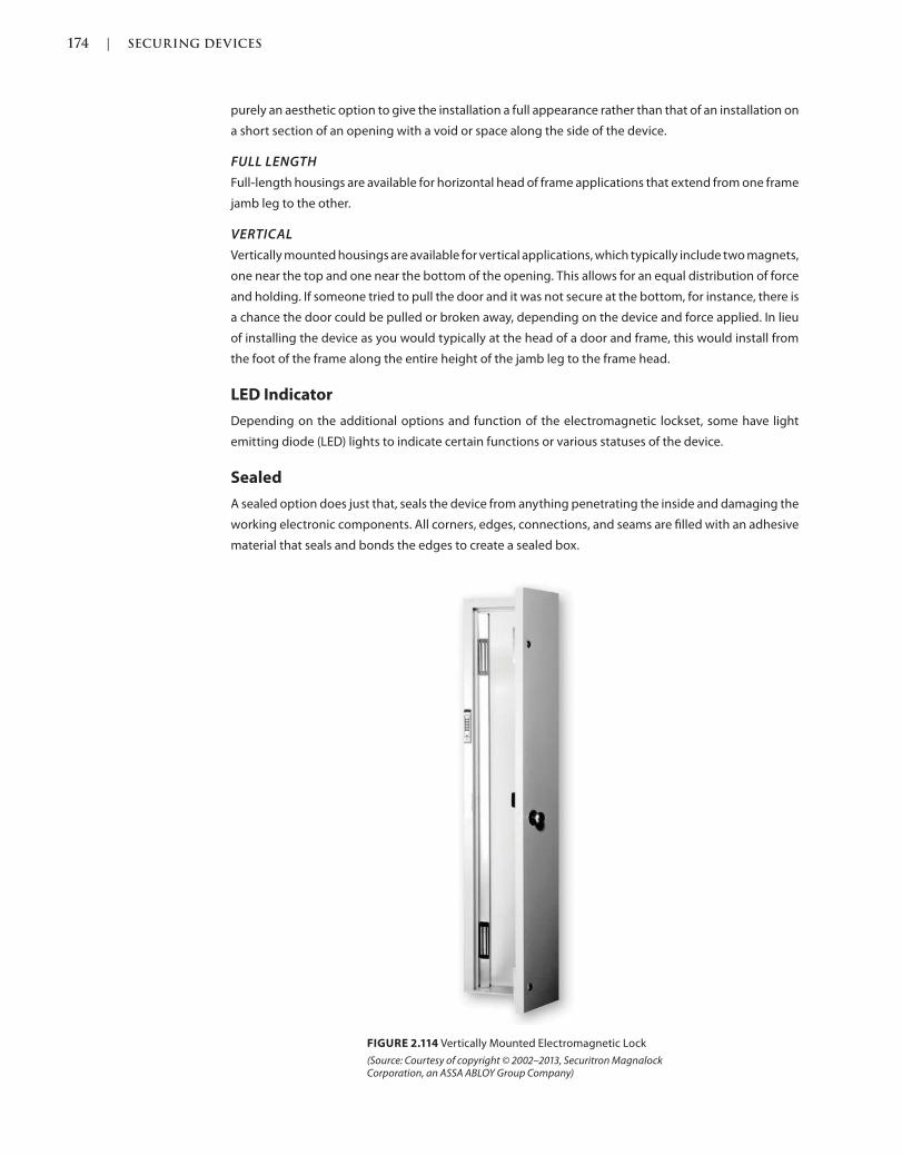
174 | SECURING DEVICES
c02.indd Page 174 03/03/2015 02:12:36:PM
purely an aesthetic option to give the installation a full appearance rather than that of an installation on
a short section of an opening with a void or space along the side of the device.
FULL LENGTH
Full-length housings are available for horizontal head of frame applications that extend from one frame
jamb leg to the other.
VERTICAL
Vertically mounted housings are available for vertical applications, which typically include two magnets,
one near the top and one near the bottom of the opening. This allows for an equal distribution of force
and holding. If someone tried to pull the door and it was not secure at the bottom, for instance, there is
a chance the door could be pulled or broken away, depending on the device and force applied. In lieu
of installing the device as you would typically at the head of a door and frame, this would install from
the foot of the frame along the entire height of the jamb leg to the frame head.
LED Indicator
Depending on the additional options and function of the electromagnetic lockset, some have light
emitting diode (LED) lights to indicate certain functions or various statuses of the device.
Sealed
A sealed option does just that, seals the device from anything penetrating the inside and damaging the
working electronic components. All corners, edges, connections, and seams are filled with an adhesive
material that seals and bonds the edges to create a sealed box.
FIGURE 2.114 Vertically Mounted Electromagnetic Lock
(Source: Courtesy of copyright © 2002–2013, Securitron Magnalock Corporation, an ASSA ABLOY Group Company)
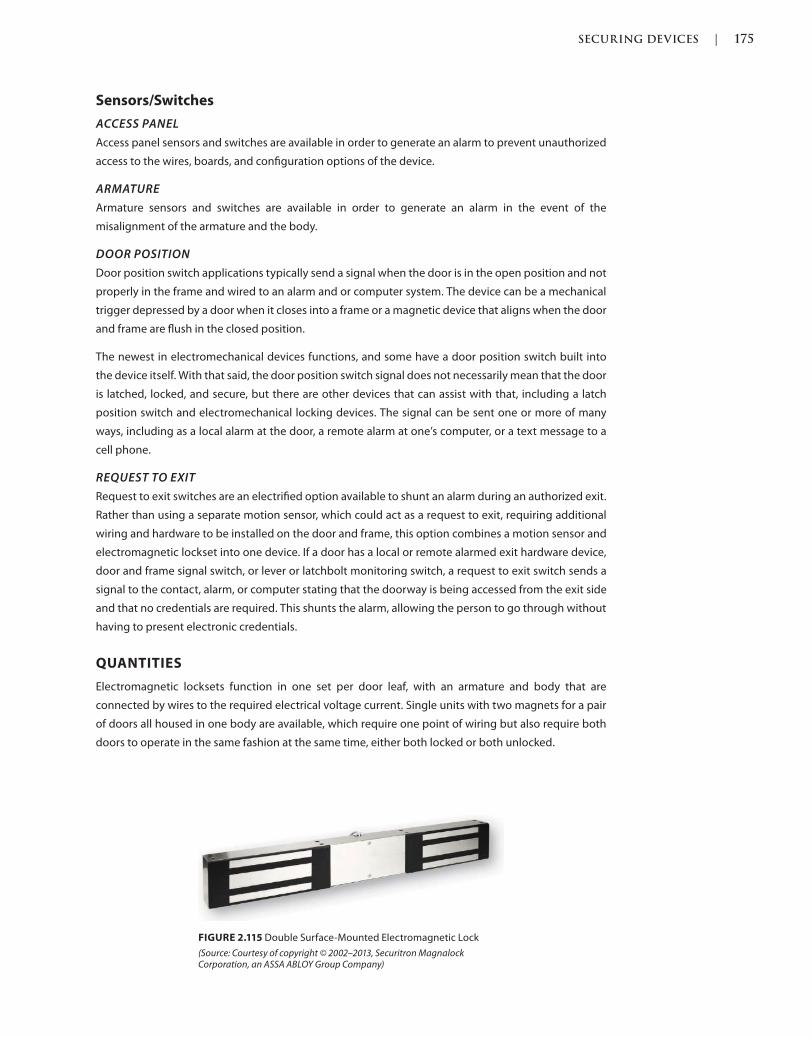
SECURING DEVICES | 175
c02.indd Page 175 03/03/2015 02:12:36:PM
Sensors/Switches
ACCESS PANEL
Access panel sensors and switches are available in order to generate an alarm to prevent unauthorized
access to the wires, boards, and configuration options of the device.
ARMATURE
Armature sensors and switches are available in order to generate an alarm in the event of the
misalignment of the armature and the body.
DOOR POSITION
Door position switch applications typically send a signal when the door is in the open position and not
properly in the frame and wired to an alarm and or computer system. The device can be a mechanical
trigger depressed by a door when it closes into a frame or a magnetic device that aligns when the door
and frame are flush in the closed position.
The newest in electromechanical devices functions, and some have a door position switch built into
the device itself. With that said, the door position switch signal does not necessarily mean that the door
is latched, locked, and secure, but there are other devices that can assist with that, including a latch
position switch and electromechanical locking devices. The signal can be sent one or more of many
ways, including as a local alarm at the door, a remote alarm at one’s computer, or a text message to a
cell phone.
REQUEST TO EXIT
Request to exit switches are an electrified option available to shunt an alarm during an authorized exit.
Rather than using a separate motion sensor, which could act as a request to exit, requiring additional
wiring and hardware to be installed on the door and frame, this option combines a motion sensor and
electromagnetic lockset into one device. If a door has a local or remote alarmed exit hardware device,
door and frame signal switch, or lever or latchbolt monitoring switch, a request to exit switch sends a
signal to the contact, alarm, or computer stating that the doorway is being accessed from the exit side
and that no credentials are required. This shunts the alarm, allowing the person to go through without
having to present electronic credentials.
QUANTITIES
Electromagnetic locksets function in one set per door leaf, with an armature and body that are
connected by wires to the required electrical voltage current. Single units with two magnets for a pair
of doors all housed in one body are available, which require one point of wiring but also require both
doors to operate in the same fashion at the same time, either both locked or both unlocked.
FIGURE 2.115 Double Surface-Mounted Electromagnetic Lock
(Source: Courtesy of copyright © 2002–2013, Securitron Magnalock Corporation, an ASSA ABLOY Group Company)
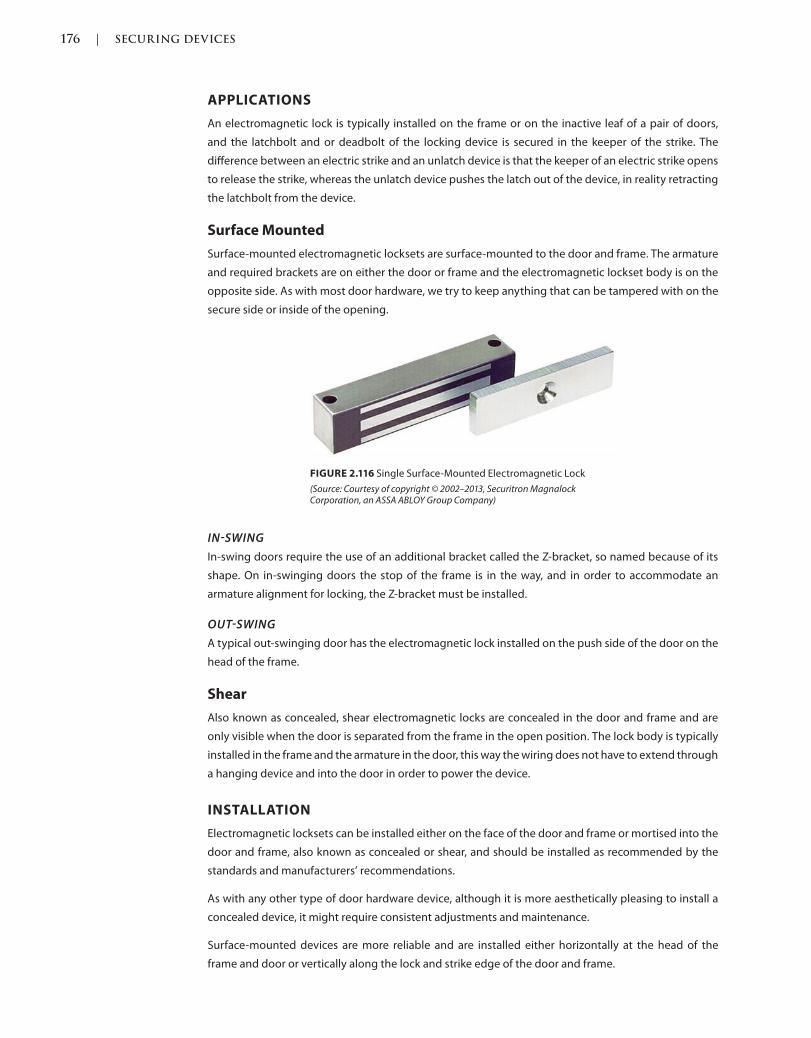
176 | SECURING DEVICES
c02.indd Page 176 03/03/2015 02:12:36:PM
APPLICATIONS
An electromagnetic lock is typically installed on the frame or on the inactive leaf of a pair of doors,
and the latchbolt and or deadbolt of the locking device is secured in the keeper of the strike. The
difference between an electric strike and an unlatch device is that the keeper of an electric strike opens
to release the strike, whereas the unlatch device pushes the latch out of the device, in reality retracting
the latchbolt from the device.
Surface Mounted
Surface-mounted electromagnetic locksets are surface-mounted to the door and frame. The armature
and required brackets are on either the door or frame and the electromagnetic lockset body is on the
opposite side. As with most door hardware, we try to keep anything that can be tampered with on the
secure side or inside of the opening.
FIGURE 2.116 Single Surface-Mounted Electromagnetic Lock
(Source: Courtesy of copyright © 2002–2013, Securitron Magnalock Corporation, an ASSA ABLOY Group Company)
INSWING
In-swing doors require the use of an additional bracket called the Z-bracket, so named because of its
shape. On in-swinging doors the stop of the frame is in the way, and in order to accommodate an
armature alignment for locking, the Z-bracket must be installed.
OUTSWING
A typical out-swinging door has the electromagnetic lock installed on the push side of the door on the
head of the frame.
Shear
Also known as concealed, shear electromagnetic locks are concealed in the door and frame and are
only visible when the door is separated from the frame in the open position. The lock body is typically
installed in the frame and the armature in the door, this way the wiring does not have to extend through
a hanging device and into the door in order to power the device.
INSTALLATION
Electromagnetic locksets can be installed either on the face of the door and frame or mortised into the
door and frame, also known as concealed or shear, and should be installed as recommended by the
standards and manufacturers’ recommendations.
As with any other type of door hardware device, although it is more aesthetically pleasing to install a
concealed device, it might require consistent adjustments and maintenance.
Surface-mounted devices are more reliable and are installed either horizontally at the head of the
frame and door or vertically along the lock and strike edge of the door and frame.
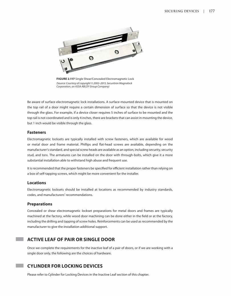
SECURING DEVICES | 177
c02.indd Page 177 03/03/2015 02:12:36:PM
Be aware of surface electromagnetic lock installations. A surface-mounted device that is mounted on
the top rail of a door might require a certain dimension of surface so that the device is not visible
through the glass. For example, if a device closer requires 5 inches of surface to be mounted and the
top rail is not coordinated and is only 4 inches, there are brackets that can assist in mounting the device,
but 1 inch would be visible through the glass.
Fasteners
Electromagnetic locksets are typically installed with screw fasteners, which are available for wood
or metal door and frame material. Phillips and flat-head screws are available, depending on the
manufacturer’s standard, and special screw heads are available as an option, including security, security
stud, and torx. The armatures can be installed on the door with through-bolts, which give it a more
substantial installation able to withstand high abuse and frequent use.
It is recommended that the proper fasteners be specified for efficient installation rather than relying on
a box of self-tapping screws, which might be more convenient for the installer.
Locations
Electromagnetic locksets should be installed at locations as recommended by industry standards,
codes, and manufacturers’ recommendations.
Preparations
Concealed or shear electromagnetic lockset preparations for metal doors and frames are typically
machined at the factory, while wood door machining can be done either in the field or at the factory,
including the drilling and tapping of screw holes. Reinforcements can be used as recommended by the
manufacturer to give the installation additional support.
ACTIVE LEAF OF PAIR OR SINGLE DOOR
Once we complete the requirements for the inactive leaf of a pair of doors, or if we are working with a
single door only, the following are the choices of hardware.
CYLINDER FOR LOCKING DEVICES
Please refer to Cylinder for Locking Devices in the Inactive Leaf section of this chapter.
FIGURE 2.117 Single Shear/Concealed Electromagnetic Lock
(Source: Courtesy of copyright © 2002–2013, Securitron Magnalock Corporation, an ASSA ABLOY Group Company)

178 | SECURING DEVICES
c02.indd Page 178 03/03/2015 02:12:36:PM
DEADLOCKS
Also Known As: Deadbolt
Considered an auxiliary lock, deadlocks are typically used for doors that are not in the path of egress
such as a closet door or as a secondary locking device as on an apartment entrance door.
PROPERTIES
Deadlock bodies are manufactured as bored, mortise, or surface mounted. In addition to the body and
depending on the function, options can include combinations of cylinders and thumb turns.
Anti-Microbial Coating
Deadlocks are available with an optional anti-microbial coating. The coating is a silver-ion–based clear
coating that helps stop the spread of bacteria. Although there are silver ions, they are not visible to
the eye and a brass or bronze finish shows its true color through the coating. Silver has been used
throughout history to help reduce the spread of bacteria and infection: Why not put it on doors and
hardware that is touched over and over again by numerous people in a day?
Backsets
Most deadlocks are available with a 2–3/4-inch backset. A backset is measured from the edge of the
door along the face to the centerline of the cylinder keyhole. Most deadlocks are also available with
a 2–3/8-inch backset. Some deadlocks are available with adjustable backsets, allowing you to switch
between 2 3/8 inches and 2 3/4 inches. Although not common, there are backset deadlocks with
custom dimensions available.
Bolt
The bolt is the locking portion of the device. It extends across the clearance, or gap between the door
and frame, and into the strike plate. Some codes state that the bolt must extend into the strike at least
½ inch. Depending on the codes, the bolt can be extended with any combination on the inside and
outside by a cylinder or thumb turn.
Case
Also known as the chassis or body of a bored or cylindrical deadlock, the case is where all of the
components are connected and work together to operate.
FIGURE 2.118 Tubular Deadlock
(Source: Courtesy of SARGENT® Manufacturing Company)

SECURING DEVICES | 179
c02.indd Page 179 03/03/2015 02:12:36:PM
Cylinder
A cylinder is a component that the key enters and rotates in order to operate the deadlock. Please refer
to Cylinder for Locking Devices in the Inactive Leaf section of this chapter.
Door Thickness
Deadlocks are available for standard 1–3/4-inch-and 1–3/8-inch-thick doors but have options to extend
the cylinder and thumb-turn components to operate thicker doors.
FIGURE 2.119 Backset Diagrams
(Source: The Graphic Standards Guide for Architectural Finishes, John Wiley & Sons, Inc.)
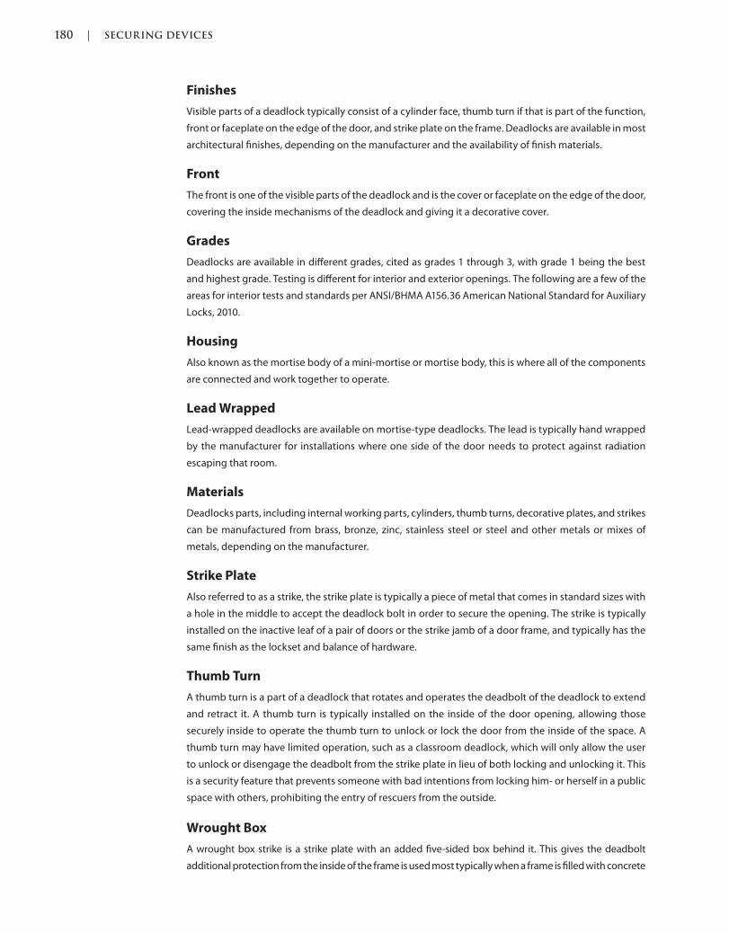
180 | SECURING DEVICES
c02.indd Page 180 03/03/2015 02:12:36:PM
Finishes
Visible parts of a deadlock typically consist of a cylinder face, thumb turn if that is part of the function,
front or faceplate on the edge of the door, and strike plate on the frame. Deadlocks are available in most
architectural finishes, depending on the manufacturer and the availability of finish materials.
Front
The front is one of the visible parts of the deadlock and is the cover or faceplate on the edge of the door,
covering the inside mechanisms of the deadlock and giving it a decorative cover.
Grades
Deadlocks are available in different grades, cited as grades 1 through 3, with grade 1 being the best
and highest grade. Testing is different for interior and exterior openings. The following are a few of the
areas for interior tests and standards per ANSI/BHMA A156.36 American National Standard for Auxiliary
Locks, 2010.
Housing
Also known as the mortise body of a mini-mortise or mortise body, this is where all of the components
are connected and work together to operate.
Lead Wrapped
Lead-wrapped deadlocks are available on mortise-type deadlocks. The lead is typically hand wrapped
by the manufacturer for installations where one side of the door needs to protect against radiation
escaping that room.
Materials
Deadlocks parts, including internal working parts, cylinders, thumb turns, decorative plates, and strikes
can be manufactured from brass, bronze, zinc, stainless steel or steel and other metals or mixes of
metals, depending on the manufacturer.
Strike Plate
Also referred to as a strike, the strike plate is typically a piece of metal that comes in standard sizes with
a hole in the middle to accept the deadlock bolt in order to secure the opening. The strike is typically
installed on the inactive leaf of a pair of doors or the strike jamb of a door frame, and typically has the
same finish as the lockset and balance of hardware.
Thumb Turn
A thumb turn is a part of a deadlock that rotates and operates the deadbolt of the deadlock to extend
and retract it. A thumb turn is typically installed on the inside of the door opening, allowing those
securely inside to operate the thumb turn to unlock or lock the door from the inside of the space. A
thumb turn may have limited operation, such as a classroom deadlock, which will only allow the user
to unlock or disengage the deadbolt from the strike plate in lieu of both locking and unlocking it. This
is a security feature that prevents someone with bad intentions from locking him- or herself in a public
space with others, prohibiting the entry of rescuers from the outside.
Wrought Box
A wrought box strike is a strike plate with an added five-sided box behind it. This gives the deadbolt
additional protection from the inside of the frame is used most typically when a frame is filled with concrete
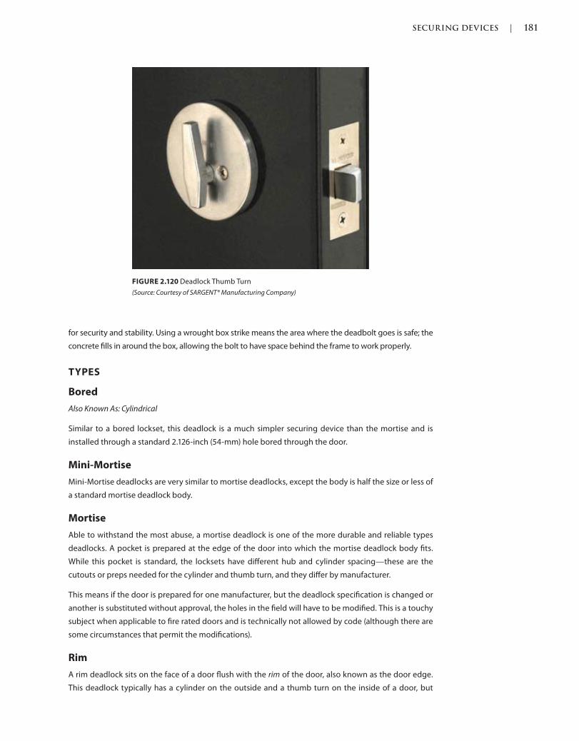
SECURING DEVICES | 181
c02.indd Page 181 03/03/2015 02:12:36:PM
for security and stability. Using a wrought box strike means the area where the deadbolt goes is safe; the
concrete fills in around the box, allowing the bolt to have space behind the frame to work properly.
TYPES
Bored
Also Known As: Cylindrical
Similar to a bored lockset, this deadlock is a much simpler securing device than the mortise and is
installed through a standard 2.126-inch (54-mm) hole bored through the door.
Mini-Mortise
Mini-Mortise deadlocks are very similar to mortise deadlocks, except the body is half the size or less of
a standard mortise deadlock body.
Mortise
Able to withstand the most abuse, a mortise deadlock is one of the more durable and reliable types
deadlocks. A pocket is prepared at the edge of the door into which the mortise deadlock body fits.
While this pocket is standard, the locksets have different hub and cylinder spacing—these are the
cutouts or preps needed for the cylinder and thumb turn, and they differ by manufacturer.
This means if the door is prepared for one manufacturer, but the deadlock specification is changed or
another is substituted without approval, the holes in the field will have to be modified. This is a touchy
subject when applicable to fire rated doors and is technically not allowed by code (although there are
some circumstances that permit the modifications).
Rim
A rim deadlock sits on the face of a door flush with the rim of the door, also known as the door edge.
This deadlock typically has a cylinder on the outside and a thumb turn on the inside of a door, but
FIGURE 2.120 Deadlock Thumb Turn
(Source: Courtesy of SARGENT® Manufacturing Company)
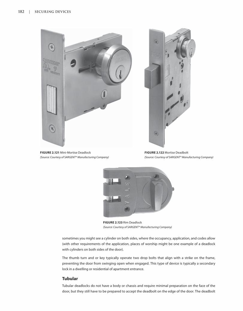
182 | SECURING DEVICES
c02.indd Page 182 03/03/2015 02:12:36:PM
FIGURE 2.121 Mini-Mortise Deadlock
(Source: Courtesy of SARGENT® Manufacturing Company)
FIGURE 2.122 Mortise Deadbolt
(Source: Courtesy of SARGENT® Manufacturing Company)
FIGURE 2.123 Rim Deadlock
(Source: Courtesy of SARGENT® Manufacturing Company)
sometimes you might see a cylinder on both sides, where the occupancy, application, and codes allow
(with other requirements of the application, places of worship might be one example of a deadlock
with cylinders on both sides of the door).
The thumb turn and or key typically operate two drop bolts that align with a strike on the frame,
preventing the door from swinging open when engaged. This type of device is typically a secondary
lock in a dwelling or residential of apartment entrance.
Tubular
Tubular deadlocks do not have a body or chassis and require minimal preparation on the face of the
door, but they still have to be prepared to accept the deadbolt on the edge of the door. The deadbolt
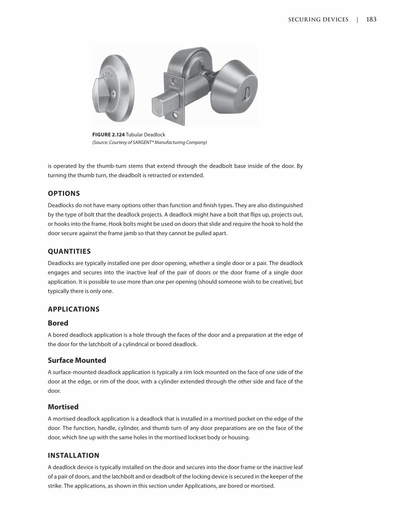
SECURING DEVICES | 183
c02.indd Page 183 03/03/2015 02:12:36:PM
is operated by the thumb-turn stems that extend through the deadbolt base inside of the door. By
turning the thumb turn, the deadbolt is retracted or extended.
OPTIONS
Deadlocks do not have many options other than function and finish types. They are also distinguished
by the type of bolt that the deadlock projects. A deadlock might have a bolt that flips up, projects out,
or hooks into the frame. Hook bolts might be used on doors that slide and require the hook to hold the
door secure against the frame jamb so that they cannot be pulled apart.
QUANTITIES
Deadlocks are typically installed one per door opening, whether a single door or a pair. The deadlock
engages and secures into the inactive leaf of the pair of doors or the door frame of a single door
application. It is possible to use more than one per opening (should someone wish to be creative), but
typically there is only one.
APPLICATIONS
Bored
A bored deadlock application is a hole through the faces of the door and a preparation at the edge of
the door for the latchbolt of a cylindrical or bored deadlock.
Surface Mounted
A surface-mounted deadlock application is typically a rim lock mounted on the face of one side of the
door at the edge, or rim of the door, with a cylinder extended through the other side and face of the
door.
Mortised
A mortised deadlock application is a deadlock that is installed in a mortised pocket on the edge of the
door. The function, handle, cylinder, and thumb turn of any door preparations are on the face of the
door, which line up with the same holes in the mortised lockset body or housing.
INSTALLATION
A deadlock device is typically installed on the door and secures into the door frame or the inactive leaf
of a pair of doors, and the latchbolt and or deadbolt of the locking device is secured in the keeper of the
strike. The applications, as shown in this section under Applications, are bored or mortised.
FIGURE 2.124 Tubular Deadlock
(Source: Courtesy of SARGENT® Manufacturing Company)

184 | SECURING DEVICES
c02.indd Page 184 03/03/2015 02:12:36:PM
If a deadlock is being installed on a stile and rail door, always confirm the lock stile dimensions to ensure
that the device will have enough room to be installed.
Fasteners
Deadlock devices are typically installed with screw fasteners, which are available for wood or metal
door and frame material. Phillips and flat-head screws are available, depending on the manufacturer’s
standard, and special screw heads are available as an option, including security, security stud, and torx.
It is recommended that the proper fasteners be specified for efficient installation rather than relying on
a box of self-tapping screws, which might be more convenient for the installer.
Locations
Deadlock devices should be installed at locations as recommended by industry standards and codes,
which are typically measured from the finished floor. Depending on the door and frame type, whether
considered standard or custom metal, wood, or aluminum, standards recommend starting the first
hinge from the finished floor.
STANDARD STEEL DOORS AND FRAMES
Standard steel doors and frames are recommended to have the centerline of the strike on the frame
installed at 48 inches.
CUSTOM STEEL DOORS AND FRAMES
Custom steel doors and frames are recommended to have the centerline of the strike on the frame
installed at 46 inches.
FLUSH WOOD DOORS AND FRAMES
Flush wood doors are recommended to have the strike on the frame installed at 48 inches.
Preparations
Deadlock device preparations are typically machined at the factory, including drilled and tapped screw
holes. With doors the preparations would be the mortised pocket or bored hole, and on the frame the
preparation would be the strike plate.
DOOR POSITION SWITCHES
Please refer to Door Position Switches in the Inactive Leaf section of this chapter.
DUMMY TRIM
Refer to the Dummy Trim in the Inactive Leaf section of this chapter.
DUTCH DOOR BOLTS
Please refer to Dutch door bolts in the Bolts section of the Inactive Leaf section of this chapter.
ELECTRIC STRIKES
Please refer to Electric Strikes in the Inactive Leaf section of this chapter.
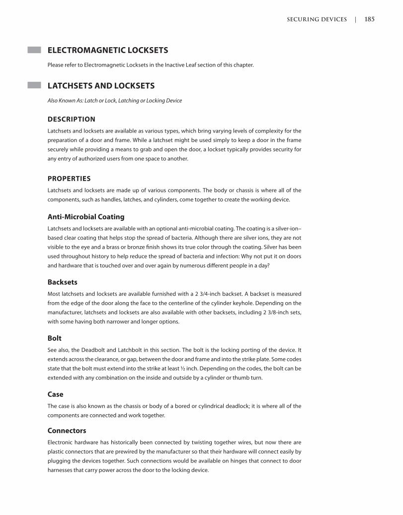
SECURING DEVICES | 185
c02.indd Page 185 03/03/2015 02:12:36:PM
ELECTROMAGNETIC LOCKSETS
Please refer to Electromagnetic Locksets in the Inactive Leaf section of this chapter.
LATCHSETS AND LOCKSETS
Also Known As: Latch or Lock, Latching or Locking Device
DESCRIPTION
Latchsets and locksets are available as various types, which bring varying levels of complexity for the
preparation of a door and frame. While a latchset might be used simply to keep a door in the frame
securely while providing a means to grab and open the door, a lockset typically provides security for
any entry of authorized users from one space to another.
PROPERTIES
Latchsets and locksets are made up of various components. The body or chassis is where all of the
components, such as handles, latches, and cylinders, come together to create the working device.
Anti-Microbial Coating
Latchsets and locksets are available with an optional anti-microbial coating. The coating is a silver-ion–
based clear coating that helps stop the spread of bacteria. Although there are silver ions, they are not
visible to the eye and a brass or bronze finish shows its true color through the coating. Silver has been
used throughout history to help reduce the spread of bacteria and infection: Why not put it on doors
and hardware that is touched over and over again by numerous different people in a day?
Backsets
Most latchsets and locksets are available furnished with a 2 3/4-inch backset. A backset is measured
from the edge of the door along the face to the centerline of the cylinder keyhole. Depending on the
manufacturer, latchsets and locksets are also available with other backsets, including 2 3/8-inch sets,
with some having both narrower and longer options.
Bolt
See also, the Deadbolt and Latchbolt in this section. The bolt is the locking porting of the device. It
extends across the clearance, or gap, between the door and frame and into the strike plate. Some codes
state that the bolt must extend into the strike at least ½ inch. Depending on the codes, the bolt can be
extended with any combination on the inside and outside by a cylinder or thumb turn.
Case
The case is also known as the chassis or body of a bored or cylindrical deadlock; it is where all of the
components are connected and work together.
Connectors
Electronic hardware has historically been connected by twisting together wires, but now there are
plastic connectors that are prewired by the manufacturer so that their hardware will connect easily by
plugging the devices together. Such connections would be available on hinges that connect to door
harnesses that carry power across the door to the locking device.
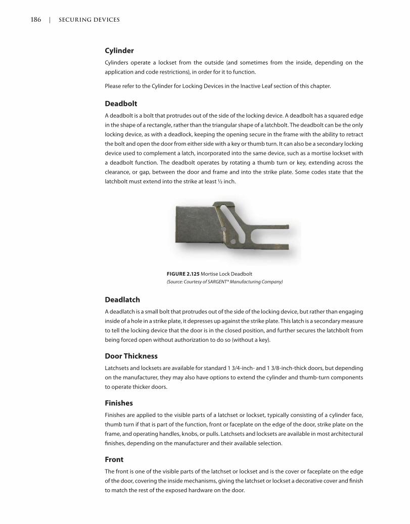
186 | SECURING DEVICES
c02.indd Page 186 03/03/2015 02:12:36:PM
Cylinder
Cylinders operate a lockset from the outside (and sometimes from the inside, depending on the
application and code restrictions), in order for it to function.
Please refer to the Cylinder for Locking Devices in the Inactive Leaf section of this chapter.
Deadbolt
A deadbolt is a bolt that protrudes out of the side of the locking device. A deadbolt has a squared edge
in the shape of a rectangle, rather than the triangular shape of a latchbolt. The deadbolt can be the only
locking device, as with a deadlock, keeping the opening secure in the frame with the ability to retract
the bolt and open the door from either side with a key or thumb turn. It can also be a secondary locking
device used to complement a latch, incorporated into the same device, such as a mortise lockset with
a deadbolt function. The deadbolt operates by rotating a thumb turn or key, extending across the
clearance, or gap, between the door and frame and into the strike plate. Some codes state that the
latchbolt must extend into the strike at least ½ inch.
FIGURE 2.125 Mortise Lock Deadbolt
(Source: Courtesy of SARGENT® Manufacturing Company)
Deadlatch
A deadlatch is a small bolt that protrudes out of the side of the locking device, but rather than engaging
inside of a hole in a strike plate, it depresses up against the strike plate. This latch is a secondary measure
to tell the locking device that the door is in the closed position, and further secures the latchbolt from
being forced open without authorization to do so (without a key).
Door Thickness
Latchsets and locksets are available for standard 1 3/4-inch- and 1 3/8-inch-thick doors, but depending
on the manufacturer, they may also have options to extend the cylinder and thumb-turn components
to operate thicker doors.
Finishes
Finishes are applied to the visible parts of a latchset or lockset, typically consisting of a cylinder face,
thumb turn if that is part of the function, front or faceplate on the edge of the door, strike plate on the
frame, and operating handles, knobs, or pulls. Latchsets and locksets are available in most architectural
finishes, depending on the manufacturer and their available selection.
Front
The front is one of the visible parts of the latchset or lockset and is the cover or faceplate on the edge
of the door, covering the inside mechanisms, giving the latchset or lockset a decorative cover and finish
to match the rest of the exposed hardware on the door.
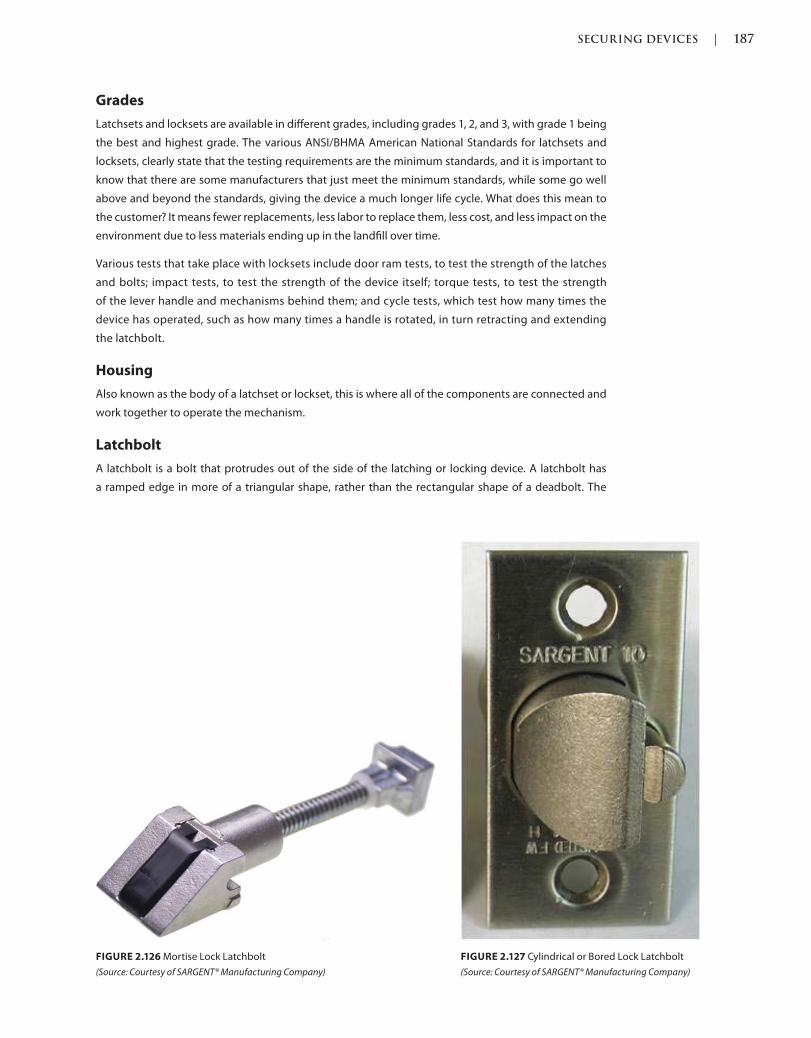
SECURING DEVICES | 187
c02.indd Page 187 03/03/2015 02:12:36:PM
Grades
Latchsets and locksets are available in different grades, including grades 1, 2, and 3, with grade 1 being
the best and highest grade. The various ANSI/BHMA American National Standards for latchsets and
locksets, clearly state that the testing requirements are the minimum standards, and it is important to
know that there are some manufacturers that just meet the minimum standards, while some go well
above and beyond the standards, giving the device a much longer life cycle. What does this mean to
the customer? It means fewer replacements, less labor to replace them, less cost, and less impact on the
environment due to less materials ending up in the landfill over time.
Various tests that take place with locksets include door ram tests, to test the strength of the latches
and bolts; impact tests, to test the strength of the device itself; torque tests, to test the strength
of the lever handle and mechanisms behind them; and cycle tests, which test how many times the
device has operated, such as how many times a handle is rotated, in turn retracting and extending
the latchbolt.
Housing
Also known as the body of a latchset or lockset, this is where all of the components are connected and
work together to operate the mechanism.
Latchbolt
A latchbolt is a bolt that protrudes out of the side of the latching or locking device. A latchbolt has
a ramped edge in more of a triangular shape, rather than the rectangular shape of a deadbolt. The
FIGURE 2.127 Cylindrical or Bored Lock Latchbolt
(Source: Courtesy of SARGENT® Manufacturing Company)
FIGURE 2.126 Mortise Lock Latchbolt
(Source: Courtesy of SARGENT® Manufacturing Company)
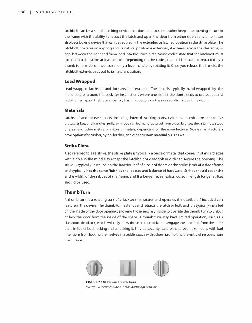
188 | SECURING DEVICES
c02.indd Page 188 03/03/2015 02:12:36:PM
latchbolt can be a simple latching device that does not lock, but rather keeps the opening secure in
the frame with the ability to retract the latch and open the door from either side at any time. It can
also be a locking device that can be secured in the extended or latched position in the strike plate. The
latchbolt operates on a spring and its natural position is extended; it extends across the clearance, or
gap, between the door and frame and into the strike plate. Some codes state that the latchbolt must
extend into the strike at least ½ inch. Depending on the codes, the latchbolt can be retracted by a
thumb turn, knob, or most commonly a lever handle by rotating it. Once you release the handle, the
latchbolt extends back out to its natural position.
Lead Wrapped
Lead-wrapped latchsets and locksets are available. The lead is typically hand-wrapped by the
manufacturer around the body for installations where one side of the door needs to protect against
radiation escaping that room possibly harming people on the nonradiation side of the door.
Materials
Latchsets’ and locksets’ parts, including internal working parts, cylinders, thumb turns, decorative
plates, strikes, and handles, pulls, or knobs can be manufactured from brass, bronze, zinc, stainless steel,
or steel and other metals or mixes of metals, depending on the manufacturer. Some manufacturers
have options for rubber, nylon, leather, and other custom material pulls as well.
Strike Plate
Also referred to as a strike, the strike plate is typically a piece of metal that comes in standard sizes
with a hole in the middle to accept the latchbolt or deadbolt in order to secure the opening. The
strike is typically installed on the inactive leaf of a pair of doors or the strike jamb of a door frame
and typically has the same finish as the lockset and balance of hardware. Strikes should cover the
entire width of the rabbet of the frame, and if a longer reveal exists, custom length longer strikes
should be used.
Thumb Turn
A thumb turn is a rotating part of a lockset that rotates and operates the deadbolt if included as a
feature in the device. The thumb turn extends and retracts the latch or bolt, and it is typically installed
on the inside of the door opening, allowing those securely inside to operate the thumb turn to unlock
or lock the door from the inside of the space. A thumb turn may have limited operation, such as a
classroom deadlock, which will only allow the user to unlock or disengage the deadbolt from the strike
plate in lieu of both locking and unlocking it. This is a security feature that prevents someone with bad
intentions from locking themselves in a public space with others, prohibiting the entry of rescuers from
the outside.
FIGURE 2.128 Various Thumb Turns
(Source: Courtesy of SARGENT® Manufacturing Company)
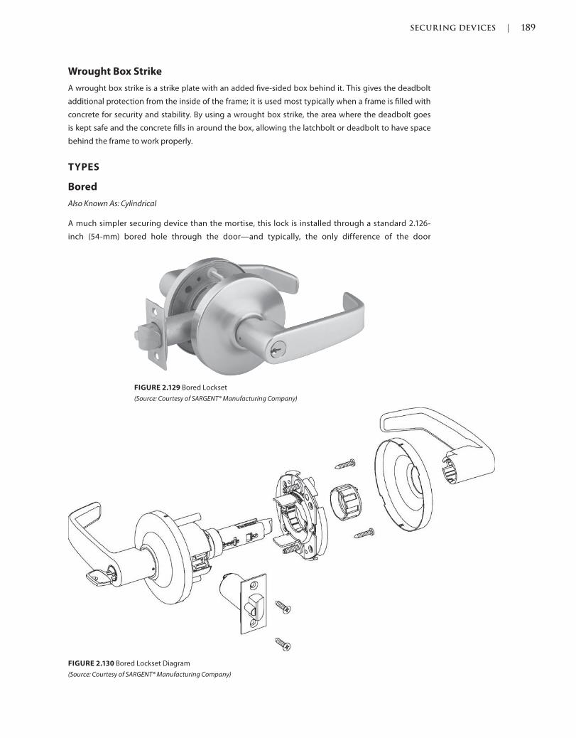
SECURING DEVICES | 189
c02.indd Page 189 03/03/2015 02:12:36:PM
Wrought Box Strike
A wrought box strike is a strike plate with an added five-sided box behind it. This gives the deadbolt
additional protection from the inside of the frame; it is used most typically when a frame is filled with
concrete for security and stability. By using a wrought box strike, the area where the deadbolt goes
is kept safe and the concrete fills in around the box, allowing the latchbolt or deadbolt to have space
behind the frame to work properly.
TYPES
Bored
Also Known As: Cylindrical
A much simpler securing device than the mortise, this lock is installed through a standard 2.126-
inch (54-mm) bored hole through the door—and typically, the only difference of the door
FIGURE 2.129 Bored Lockset
(Source: Courtesy of SARGENT® Manufacturing Company)
FIGURE 2.130 Bored Lockset Diagram
(Source: Courtesy of SARGENT® Manufacturing Company)
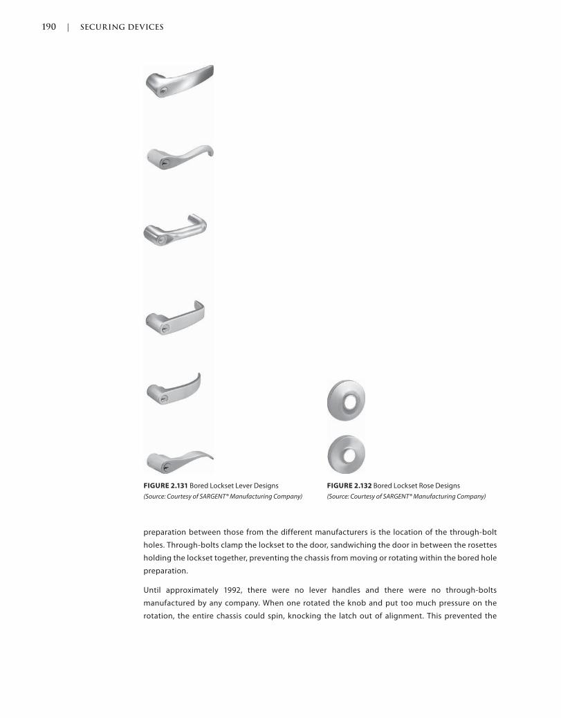
190 | SECURING DEVICES
c02.indd Page 190 03/03/2015 02:12:36:PM
FIGURE 2.131 Bored Lockset Lever Designs
(Source: Courtesy of SARGENT® Manufacturing Company)
FIGURE 2.132 Bored Lockset Rose Designs
(Source: Courtesy of SARGENT® Manufacturing Company)
preparation between those from the different manufacturers is the location of the through-bolt
holes. Through-bolts clamp the lockset to the door, sandwiching the door in between the rosettes
holding the lockset together, preventing the chassis from moving or rotating within the bored hole
preparation.
Until approximately 1992, there were no lever handles and there were no through-bolts
manufactured by any company. When one rotated the knob and put too much pressure on the
rotation, the entire chassis could spin, knocking the latch out of alignment. This prevented the
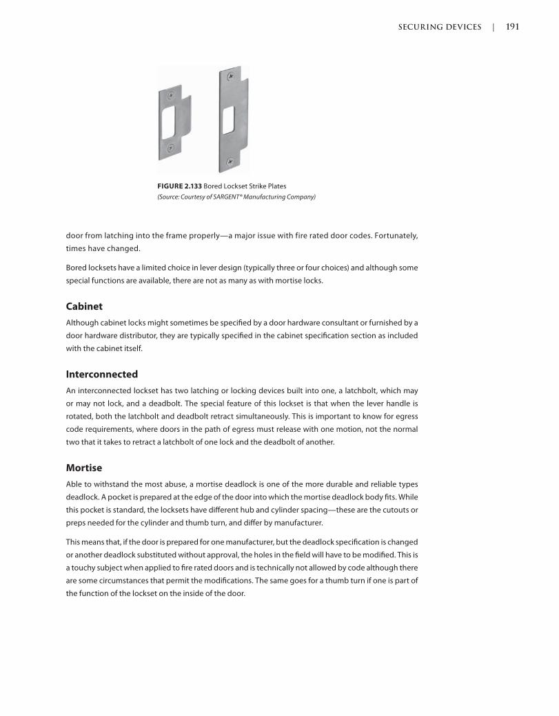
SECURING DEVICES | 191
c02.indd Page 191 03/03/2015 02:12:36:PM
door from latching into the frame properly—a major issue with fire rated door codes. Fortunately,
times have changed.
Bored locksets have a limited choice in lever design (typically three or four choices) and although some
special functions are available, there are not as many as with mortise locks.
Cabinet
Although cabinet locks might sometimes be specified by a door hardware consultant or furnished by a
door hardware distributor, they are typically specified in the cabinet specification section as included
with the cabinet itself.
Interconnected
An interconnected lockset has two latching or locking devices built into one, a latchbolt, which may
or may not lock, and a deadbolt. The special feature of this lockset is that when the lever handle is
rotated, both the latchbolt and deadbolt retract simultaneously. This is important to know for egress
code requirements, where doors in the path of egress must release with one motion, not the normal
two that it takes to retract a latchbolt of one lock and the deadbolt of another.
Mortise
Able to withstand the most abuse, a mortise deadlock is one of the more durable and reliable types
deadlock. A pocket is prepared at the edge of the door into which the mortise deadlock body fits. While
this pocket is standard, the locksets have different hub and cylinder spacing—these are the cutouts or
preps needed for the cylinder and thumb turn, and differ by manufacturer.
This means that, if the door is prepared for one manufacturer, but the deadlock specification is changed
or another deadlock substituted without approval, the holes in the field will have to be modified. This is
a touchy subject when applied to fire rated doors and is technically not allowed by code although there
are some circumstances that permit the modifications. The same goes for a thumb turn if one is part of
the function of the lockset on the inside of the door.
FIGURE 2.133 Bored Lockset Strike Plates
(Source: Courtesy of SARGENT® Manufacturing Company)
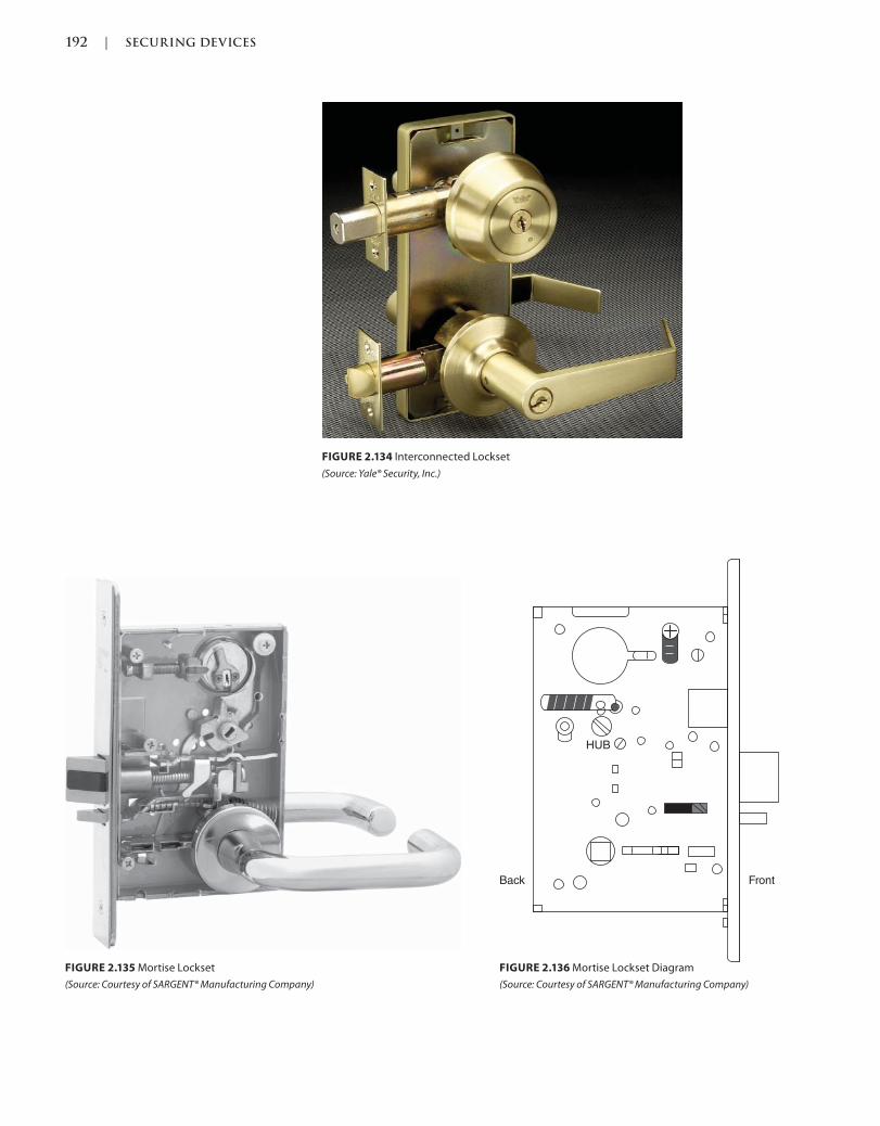
192 | SECURING DEVICES
c02.indd Page 192 03/03/2015 02:12:36:PM
FIGURE 2.134 Interconnected Lockset
(Source: Yale® Security, Inc.)
FrontBack
HUB
FIGURE 2.135 Mortise Lockset
(Source: Courtesy of SARGENT® Manufacturing Company)
FIGURE 2.136 Mortise Lockset Diagram
(Source: Courtesy of SARGENT® Manufacturing Company)

SECURING DEVICES | 193
c02.indd Page 193 03/03/2015 02:12:36:PM
FIGURE 2.138 Mortise Lock Roseless Trim Design
(Source: Courtesy of SARGENT® Manufacturing Company)
For mortise locksets that have a deadbolt feature, it is important to know that the deadbolt is retracted
simultaneously with the latchbolt when the handle is rotated, for egress code requirements. Doors in
the path of egress must release with one motion, not the normal two that it takes to retract a latchbolt
of one lock and the deadbolt of another.
FIGURE 2.137 Mortise Lock Lever Designs
(Source: Courtesy of Scott J. Tobias)
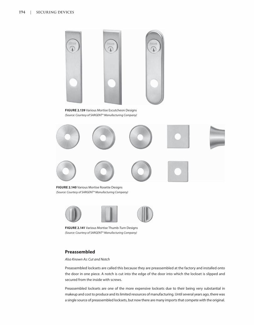
194 | SECURING DEVICES
c02.indd Page 194 03/03/2015 02:12:36:PM
FIGURE 2.141 Various Mortise Thumb-Turn Designs
(Source: Courtesy of SARGENT® Manufacturing Company)
FIGURE 2.139 Various Mortise Escutcheon Designs
(Source: Courtesy of SARGENT® Manufacturing Company)
FIGURE 2.140 Various Mortise Rosette Designs
(Source: Courtesy of SARGENT® Manufacturing Company)
Preassembled
Also Known As: Cut and Notch
Preassembled locksets are called this because they are preassembled at the factory and installed onto
the door in one piece. A notch is cut into the edge of the door into which the lockset is slipped and
secured from the inside with screws.
Preassembled locksets are one of the more expensive locksets due to their being very substantial in
makeup and cost to produce and its limited resources of manufacturing. Until several years ago, there was
a single source of preassembled locksets, but now there are many imports that compete with the original.
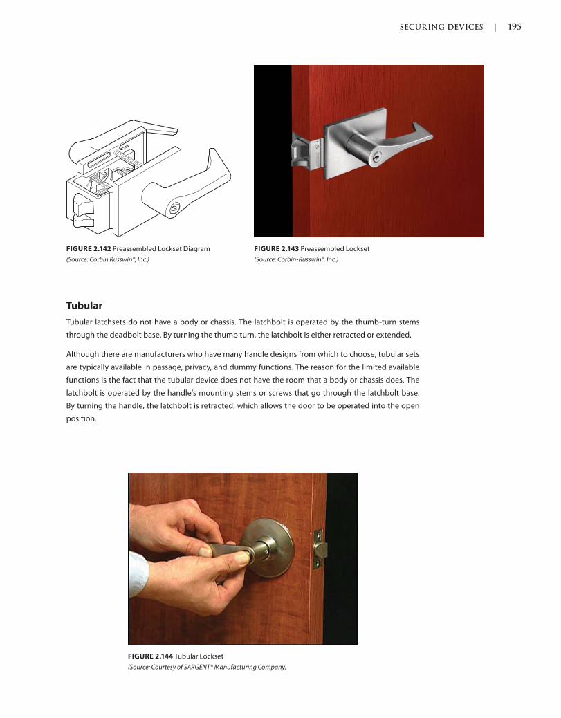
SECURING DEVICES | 195
c02.indd Page 195 03/03/2015 02:12:36:PM
FIGURE 2.144 Tubular Lockset
(Source: Courtesy of SARGENT® Manufacturing Company)
FIGURE 2.143 Preassembled Lockset
(Source: Corbin-Russwin®, Inc.)
FIGURE 2.142 Preassembled Lockset Diagram
(Source: Corbin Russwin®, Inc.)
Tubular
Tubular latchsets do not have a body or chassis. The latchbolt is operated by the thumb-turn stems
through the deadbolt base. By turning the thumb turn, the latchbolt is either retracted or extended.
Although there are manufacturers who have many handle designs from which to choose, tubular sets
are typically available in passage, privacy, and dummy functions. The reason for the limited available
functions is the fact that the tubular device does not have the room that a body or chassis does. The
latchbolt is operated by the handle’s mounting stems or screws that go through the latchbolt base.
By turning the handle, the latchbolt is retracted, which allows the door to be operated into the open
position.

196 | SECURING DEVICES
c02.indd Page 196 03/03/2015 02:12:36:PM
FIGURE 2.145 Tubular Lockset Lever Designs [c02f145.tif]
(Source: Courtesy of SARGENT® Manufacturing Company)
OPTIONS
Connectors
Electronic hardware has historically been connected by twisting together wires, but now there are
plastic connectors that are prewired by the manufacturer so that their hardware will connect easily by
plugging the devices together. Such connections would be available on hinges that connect to door
harnesses that carry power across the door to the locking device.
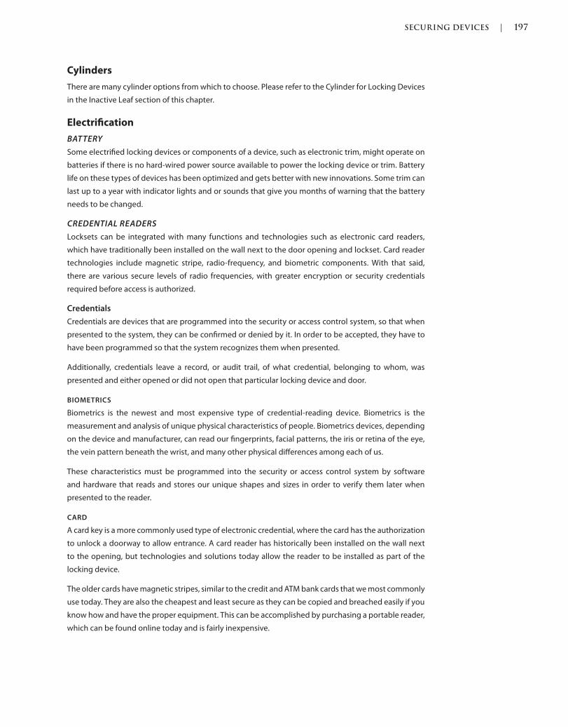
SECURING DEVICES | 197
c02.indd Page 197 03/03/2015 02:12:36:PM
Cylinders
There are many cylinder options from which to choose. Please refer to the Cylinder for Locking Devices
in the Inactive Leaf section of this chapter.
Electrification
BATTERY
Some electrified locking devices or components of a device, such as electronic trim, might operate on
batteries if there is no hard-wired power source available to power the locking device or trim. Battery
life on these types of devices has been optimized and gets better with new innovations. Some trim can
last up to a year with indicator lights and or sounds that give you months of warning that the battery
needs to be changed.
CREDENTIAL READERS
Locksets can be integrated with many functions and technologies such as electronic card readers,
which have traditionally been installed on the wall next to the door opening and lockset. Card reader
technologies include magnetic stripe, radio-frequency, and biometric components. With that said,
there are various secure levels of radio frequencies, with greater encryption or security credentials
required before access is authorized.
Credentials
Credentials are devices that are programmed into the security or access control system, so that when
presented to the system, they can be confirmed or denied by it. In order to be accepted, they have to
have been programmed so that the system recognizes them when presented.
Additionally, credentials leave a record, or audit trail, of what credential, belonging to whom, was
presented and either opened or did not open that particular locking device and door.
BIOMETRICS
Biometrics is the newest and most expensive type of credential-reading device. Biometrics is the
measurement and analysis of unique physical characteristics of people. Biometrics devices, depending
on the device and manufacturer, can read our fingerprints, facial patterns, the iris or retina of the eye,
the vein pattern beneath the wrist, and many other physical differences among each of us.
These characteristics must be programmed into the security or access control system by software
and hardware that reads and stores our unique shapes and sizes in order to verify them later when
presented to the reader.
CARD
A card key is a more commonly used type of electronic credential, where the card has the authorization
to unlock a doorway to allow entrance. A card reader has historically been installed on the wall next
to the opening, but technologies and solutions today allow the reader to be installed as part of the
locking device.
The older cards have magnetic stripes, similar to the credit and ATM bank cards that we most commonly
use today. They are also the cheapest and least secure as they can be copied and breached easily if you
know how and have the proper equipment. This can be accomplished by purchasing a portable reader,
which can be found online today and is fairly inexpensive.
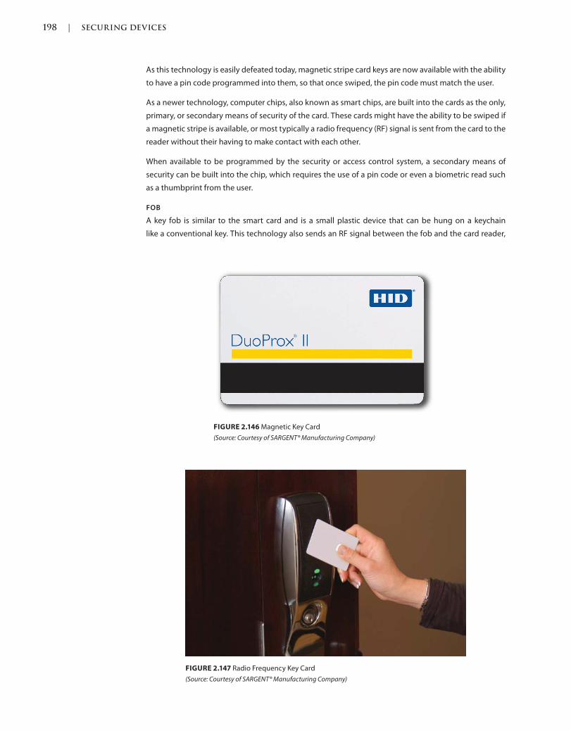
198 | SECURING DEVICES
c02.indd Page 198 03/03/2015 02:12:36:PM
As this technology is easily defeated today, magnetic stripe card keys are now available with the ability
to have a pin code programmed into them, so that once swiped, the pin code must match the user.
As a newer technology, computer chips, also known as smart chips, are built into the cards as the only,
primary, or secondary means of security of the card. These cards might have the ability to be swiped if
a magnetic stripe is available, or most typically a radio frequency (RF) signal is sent from the card to the
reader without their having to make contact with each other.
When available to be programmed by the security or access control system, a secondary means of
security can be built into the chip, which requires the use of a pin code or even a biometric read such
as a thumbprint from the user.
FOB
A key fob is similar to the smart card and is a small plastic device that can be hung on a keychain
like a conventional key. This technology also sends an RF signal between the fob and the card reader,
FIGURE 2.146 Magnetic Key Card
(Source: Courtesy of SARGENT® Manufacturing Company)
FIGURE 2.147 Radio Frequency Key Card
(Source: Courtesy of SARGENT® Manufacturing Company)
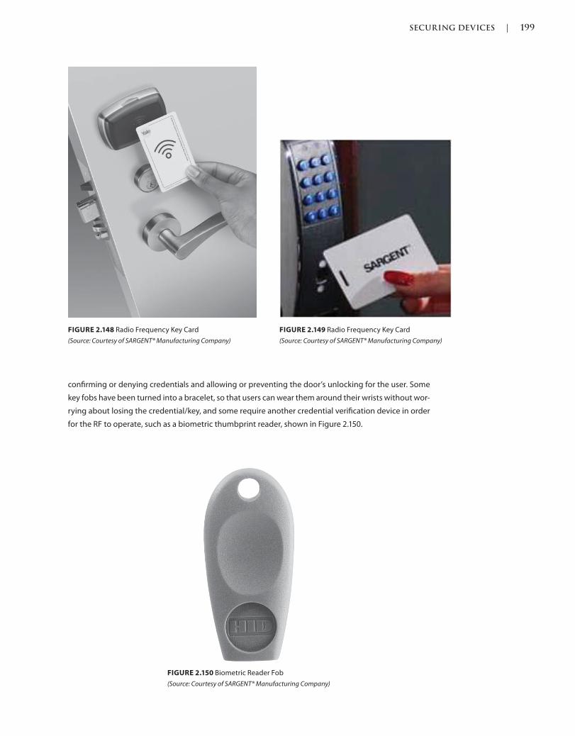
SECURING DEVICES | 199
c02.indd Page 199 03/03/2015 02:12:36:PM
confirming or denying credentials and allowing or preventing the door’s unlocking for the user. Some
key fobs have been turned into a bracelet, so that users can wear them around their wrists without wor-
rying about losing the credential/key, and some require another credential verification device in order
for the RF to operate, such as a biometric thumbprint reader, shown in Figure 2.150.
FIGURE 2.149 Radio Frequency Key Card
(Source: Courtesy of SARGENT® Manufacturing Company)
FIGURE 2.148 Radio Frequency Key Card
(Source: Courtesy of SARGENT® Manufacturing Company)
FIGURE 2.150 Biometric Reader Fob
(Source: Courtesy of SARGENT® Manufacturing Company)
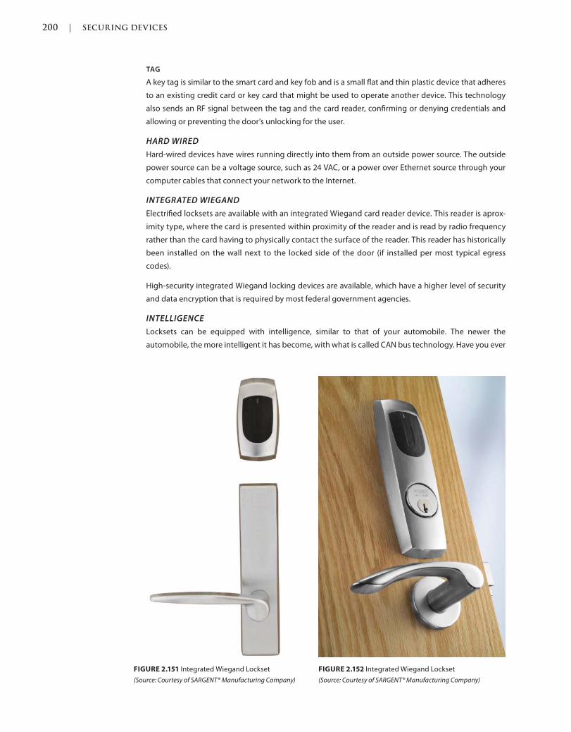
200 | SECURING DEVICES
c02.indd Page 200 03/03/2015 02:12:36:PM
TAG
A key tag is similar to the smart card and key fob and is a small flat and thin plastic device that adheres
to an existing credit card or key card that might be used to operate another device. This technology
also sends an RF signal between the tag and the card reader, confirming or denying credentials and
allowing or preventing the door’s unlocking for the user.
HARD WIRED
Hard-wired devices have wires running directly into them from an outside power source. The outside
power source can be a voltage source, such as 24 VAC, or a power over Ethernet source through your
computer cables that connect your network to the Internet.
INTEGRATED WIEGAND
Electrified locksets are available with an integrated Wiegand card reader device. This reader is aprox-
imity type, where the card is presented within proximity of the reader and is read by radio frequency
rather than the card having to physically contact the surface of the reader. This reader has historically
been installed on the wall next to the locked side of the door (if installed per most typical egress
codes).
High-security integrated Wiegand locking devices are available, which have a higher level of security
and data encryption that is required by most federal government agencies.
INTELLIGENCE
Locksets can be equipped with intelligence, similar to that of your automobile. The newer the
automobile, the more intelligent it has become, with what is called CAN bus technology. Have you ever
FIGURE 2.151 Integrated Wiegand Lockset
(Source: Courtesy of SARGENT® Manufacturing Company)
FIGURE 2.152 Integrated Wiegand Lockset
(Source: Courtesy of SARGENT® Manufacturing Company)
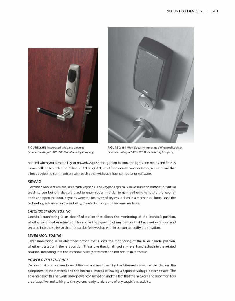
SECURING DEVICES | 201
c02.indd Page 201 03/03/2015 02:12:36:PM
noticed when you turn the key, or nowadays push the ignition button, the lights and beeps and flashes
almost talking to each other? That is CAN bus, CAN, short for controller area network, is a standard that
allows devices to communicate with each other without a host computer or software.
KEYPAD
Electrified locksets are available with keypads. The keypads typically have numeric buttons or virtual
touch screen buttons that are used to enter codes in order to gain authority to rotate the lever or
knob and open the door. Keypads were the first type of keyless lockset in a mechanical form. Once the
technology advanced in the industry, the electronic option became available.
LATCHBOLT MONITORING
Latchbolt monitoring is an electrified option that allows the monitoring of the latchbolt position,
whether extended or retracted. This allows the signaling of any devices that have not extended and
secured into the strike so that this can be followed up with in person to rectify the situation.
LEVER MONITORING
Lever monitoring is an electrified option that allows the monitoring of the lever handle position,
whether rotated or in the rest position. This allows the signaling of any lever handle that is in the rotated
position, indicating that the latchbolt is likely retracted and not secure in the strike.
POWER OVER ETHERNET
Devices that are powered over Ethernet are energized by the Ethernet cable that hard-wires the
computers to the network and the Internet, instead of having a separate voltage power source. The
advantages of this network is low power consumption and the fact that the network and door monitors
are always live and talking to the system, ready to alert one of any suspicious activity.
FIGURE 2.153 Integrated Wiegand Lockset
(Source: Courtesy of SARGENT® Manufacturing Company)
FIGURE 2.154 High-Security Integrated Wiegand Lockset
(Source: Courtesy of SARGENT® Manufacturing Company)
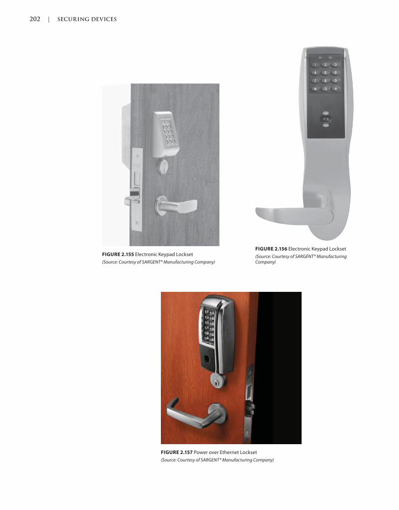
202 | SECURING DEVICES
c02.indd Page 202 03/03/2015 02:12:36:PM
FIGURE 2.156 Electronic Keypad Lockset
(Source: Courtesy of SARGENT® Manufacturing Company)
FIGURE 2.155 Electronic Keypad Lockset
(Source: Courtesy of SARGENT® Manufacturing Company)
FIGURE 2.157 Power over Ethernet Lockset
(Source: Courtesy of SARGENT® Manufacturing Company)
SECURING DEVICES | 203
c02.indd Page 203 03/03/2015 02:12:36:PM
REQUEST TO EXIT SWITCH
Request to exit switches are an electrified option available to shunt an alarm during an authorized
exit. If a door has a local or remote alarmed exit hardware device, door and frame signal switch,
lever or latchbolt monitoring switch, a request to exit switch sends a signal to the contact, alarm,
or computer stating that the doorway is being accessed from the exit side and that no credentials
are required. This shunts the alarm allowing the person to go through without having to present
electronic credentials.
TRIM
Electrified trim is available on the outside of an exit device door so that a door can be accessed from the
outside with the use of an electronic access control system. Typically rigid, when a switch such as a card
reader authorizes the credentials presented to it, the trim unlocks and is able to be rotated to retract
the latchbolt, pull the door forward, and gain entry to the space.
Fail Safe
Fail-safe door trim is available to tie into a fire alarm system. This trim only locks when power is
applied to the opening and unlocks when power is released. This function uses power all of the time
but is necessary to meet the codes in certain situations if electrification is necessary at the opening.
The devices are manufactured differently, depending on the manufacturer and options, and can be
operated by solenoid or a motorized mechanism, which retracts and throws the bolt accordingly or
simply allows the lever or knob to be rotated to retract the latch manually.
Fail Secure
Fail-secure door trim is available for locking and unlocking a device. This trim only unlocks when power
is applied to the opening and locks when power is released. This device uses less power than fail safe,
as the power is only used when necessary to open the device. The devices are manufactured differently,
depending on the manufacturer and options, and can be operated by solenoid or a motorized
mechanism, which retracts and throws the bolt accordingly or simply allows the lever or knob to be
rotated to retract the latch manually.
WIRELESS
In addition to the common household wireless fidelity (WiFi) that we all know and use for our wireless
Internet access through the use of a wireless router connected to the modem, there are other wireless
technologies available and incorporated into many existing mechanics, including electronic door
locksets. Some of these low-power-consumption wireless technologies send wireless signals to local
hubs separate from the 802.11 routers that we are used to in our homes.
WIRELESS FIDELITY
Devices that have WiFi technology are typically powered by battery. These devices communicate on
the same 802.11 wireless networks that we use to transmit our Internet signal from the hard-wired
modem into the air so that our computers and mobile devices can connect and use the signal to do
various things, most commonly access the Internet. New devices that incorporate both the modem and
router are available from some Internet access providers.
The WiFi sends and receives data to and from the computers and system. The advantages of this network
is low power battery consumption and easy network installation and communication, especially in
existing conditions where running hard wires is not efficient or sometimes even possible due to wall
and frame materials. Although the system is not live all of the time, the network and door monitors
“wake up” and talk to the system whenever there is any suspicious activity.
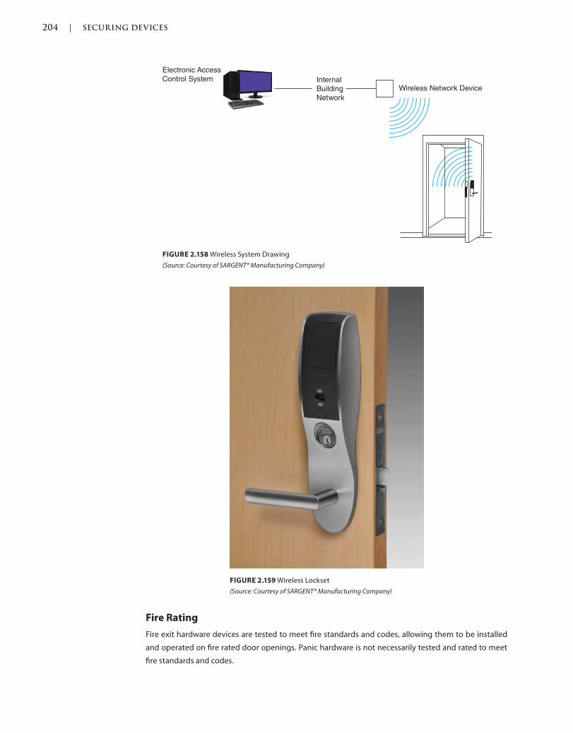
204 | SECURING DEVICES
c02.indd Page 204 03/03/2015 02:12:36:PM
FIGURE 2.159 Wireless Lockset
(Source: Courtesy of SARGENT® Manufacturing Company)
Electronic Access
Control System Internal
Building
Network
Wireless Network Device
FIGURE 2.158 Wireless System Drawing
(Source: Courtesy of SARGENT® Manufacturing Company)
Fire Rating
Fire exit hardware devices are tested to meet fire standards and codes, allowing them to be installed
and operated on fire rated door openings. Panic hardware is not necessarily tested and rated to meet
fire standards and codes.
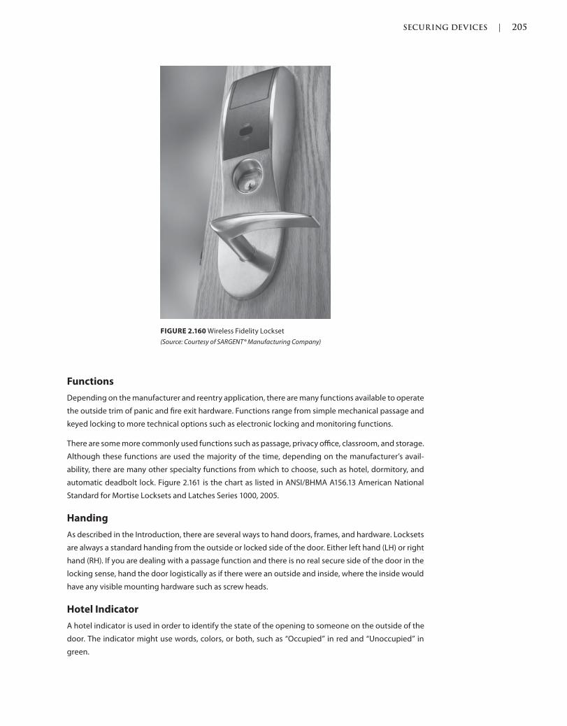
SECURING DEVICES | 205
c02.indd Page 205 03/03/2015 02:12:36:PM
Functions
Depending on the manufacturer and reentry application, there are many functions available to operate
the outside trim of panic and fire exit hardware. Functions range from simple mechanical passage and
keyed locking to more technical options such as electronic locking and monitoring functions.
There are some more commonly used functions such as passage, privacy office, classroom, and storage.
Although these functions are used the majority of the time, depending on the manufacturer’s avail-
ability, there are many other specialty functions from which to choose, such as hotel, dormitory, and
automatic deadbolt lock. Figure 2.161 is the chart as listed in ANSI/BHMA A156.13 American National
Standard for Mortise Locksets and Latches Series 1000, 2005.
Handing
As described in the Introduction, there are several ways to hand doors, frames, and hardware. Locksets
are always a standard handing from the outside or locked side of the door. Either left hand (LH) or right
hand (RH). If you are dealing with a passage function and there is no real secure side of the door in the
locking sense, hand the door logistically as if there were an outside and inside, where the inside would
have any visible mounting hardware such as screw heads.
Hotel Indicator
A hotel indicator is used in order to identify the state of the opening to someone on the outside of the
door. The indicator might use words, colors, or both, such as “Occupied” in red and “Unoccupied” in
green.
FIGURE 2.160 Wireless Fidelity Lockset
(Source: Courtesy of SARGENT® Manufacturing Company)
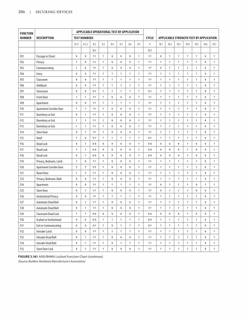
206 | SECURING DEVICES
c02.indd Page 206 03/03/2015 02:12:36:PM
FUNCTION
NUMBER DESCRIPTION
APPLICABLE OPERATIONAL TEST BY APPLICATION
CYCLE APPLICABLE STRENGTH TEST BY APPLICATIONTEST NUMBERS
8.1.1 8.1.2 8.2 8.3 8.4 8.5 8.6 8.7 9 10.1 10.2 10.3 10.4 10.5 10.6 10.7
O-I O-I
F01 Passage or Closet N N Y-Y Y N N N Y Y-Y N Y Y Y Y N Y
F02 Privacy Y N Y-Y Y N N N Y Y-Y Y Y Y Y Y N Y
F03 Communicating Y N Y-Y Y N N N Y Y-Y N Y Y Y Y N Y
F04 Entry N N Y-Y Y Y Y Y Y Y-Y Y Y Y Y Y N Y
F05 Classroom N N Y-Y Y Y Y Y Y Y-Y Y Y Y Y Y N Y
F06 Holdback N N Y-Y Y Y Y Y Y Y-Y Y Y Y Y Y N Y
F07 Storeroom N N N-Y Y Y Y Y Y N-Y Y Y Y Y Y N Y
F08 Front Door Y Y Y-Y Y N N N Y Y-Y Y Y Y Y Y N Y
F09 Apartment N N Y-Y Y Y Y Y Y Y-Y Y Y Y Y Y N Y
F10 Apartment Corridor Door Y Y Y-Y Y N N N Y Y-Y Y Y Y Y Y N Y
F11 Dormitory or Exit N Y Y-Y Y N N N Y Y-Y Y Y Y Y Y N Y
F12 Dormitory or Exit Y Y Y-Y Y N N N Y Y-Y Y Y Y Y Y N Y
F13 Dormitory or Exit Y Y Y-Y Y N N N Y Y-Y Y Y Y Y Y N Y
F14 Store Door N Y Y-Y Y N N N Y Y-Y Y Y Y Y Y N Y
F15 Hotel Y N N-Y Y Y Y Y Y N-Y Y Y Y Y Y N Y
F16 Dead Lock N Y N-N N N N N Y N-N N N N Y N N Y
F17 Dead Lock Y Y N-N N N N N Y N-N N N N Y N N Y
F18 Dead Lock N Y N-N N N N N Y N-N N N N Y N N Y
F19 Privacy, Bedroom, Latch Y N Y-Y Y N N N Y Y-Y Y Y Y Y Y N Y
F20 Apartment Corridor Door Y Y Y-Y Y N N N Y Y-Y Y Y Y Y Y N Y
F21 Room Door Y Y Y-Y Y N N N Y Y-Y Y Y Y Y Y N Y
F22 Privacy, Bedroom, Bath N N Y-Y Y N N N Y Y-Y Y Y Y Y Y N Y
F24 Apartment N N Y-Y Y Y Y Y Y Y-Y N Y Y Y N Y Y
F25 Store Door N Y Y-Y Y N N N Y Y-Y N Y Y Y N N Y
F26 Institutional Privacy N N Y-Y Y Y Y Y Y Y-Y Y Y Y Y Y N Y
F27 Automatic Dead Bolt N Y Y-Y Y N N N Y Y-Y Y Y Y Y Y N Y
F28 Automatic Dead Bolt N Y Y-Y Y N N N Y Y-Y Y Y Y Y Y N Y
F29 Classroom Dead Lock Y Y N-N N N N N Y N-N N N N Y N N Y
F30 Asylum or Institutional N N N-N Y Y Y Y Y N-N Y Y Y Y Y N Y
F31 Exit or Communicating N N N-Y Y N Y Y Y N-Y Y Y Y Y Y N Y
F32 Intruder Latch N N Y-Y Y Y Y Y Y Y-Y Y Y Y Y Y N Y
F33 Intruder Dead Bolt N Y Y-Y Y N N N Y Y-Y Y Y Y Y Y N Y
F34 Intruder Dead Bolt N Y Y-Y Y N Y Y Y Y-Y Y Y Y Y Y N Y
F35 Store Door Lock N Y Y-Y Y N N N Y Y-Y Y Y Y Y Y N Y
FIGURE 2.161 ANSI/BHMA Lockset Function Chart (continues)
(Source: Builders Hardware Manufacturers Association)
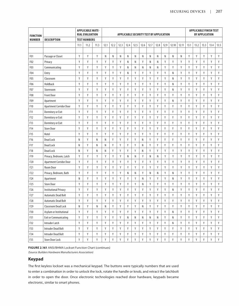
SECURING DEVICES | 207
c02.indd Page 207 03/03/2015 02:12:36:PM
FUNCTION NUMBER
APPLICABLE MATERIAL EVALUATION APPLICABLE SECURITY TEST BY APPLICATION
APPLICABLE FINISH TEST BY APPLICATION
DESCRIPTION TEST NUMBERS
11.1 11.2 11.3 12.1 12.2 12.3 12.4 12.5 12.6 12.7 12.8 12.9 12.10 12.11 13.1 13.2 13.3 13.4 13.5
F01 Passage or Closet Y Y Y N N N N N N N N N N N Y Y Y Y Y
F02 Privacy Y Y Y Y Y Y N N Y N N Y Y Y Y Y Y Y Y
F03 Communicating Y Y Y Y Y Y N N N N N Y Y Y Y Y Y Y Y
F04 Entry Y Y Y Y Y Y N Y Y Y Y Y N Y Y Y Y Y Y
F05 Classroom Y Y Y Y Y Y Y Y Y Y Y Y N Y Y Y Y Y Y
F06 Holdback Y Y Y Y Y Y Y Y Y Y Y Y N Y Y Y Y Y Y
F07 Storeroom Y Y Y Y Y Y Y Y Y Y Y Y N Y Y Y Y Y Y
F08 Front Door Y Y Y Y Y Y Y Y Y Y Y Y Y Y Y Y Y Y Y
F09 Apartment Y Y Y Y Y Y Y Y Y Y Y Y N Y Y Y Y Y Y
F10 Apartment Corridor Door Y Y Y Y Y Y Y Y Y Y Y Y Y Y Y Y Y Y Y
F11 Dormitory or Exit Y Y Y Y Y Y Y Y Y Y Y Y Y Y Y Y Y Y Y
F12 Dormitory or Exit Y Y Y Y Y Y Y Y Y Y Y Y Y Y Y Y Y Y Y
F13 Dormitory or Exit Y Y Y Y Y Y Y Y Y Y Y Y Y Y Y Y Y Y Y
F14 Store Door Y Y Y Y Y Y Y Y Y Y Y Y Y Y Y Y Y Y Y
F15 Hotel Y Y Y Y Y Y Y Y Y Y Y Y Y Y Y Y Y Y Y
F16 Dead Lock N Y N N Y Y Y Y N Y Y Y Y Y Y Y Y Y Y
F17 Dead Lock N Y N N Y Y Y Y N Y Y Y Y Y Y Y Y Y Y
F18 Dead Lock N Y N N Y Y Y Y N Y Y Y Y Y Y Y Y Y Y
F19 Privacy, Bedroom, Latch Y Y Y Y Y Y N N Y N N Y Y Y Y Y Y Y Y
F20 Apartment Corridor Door Y Y Y Y Y Y Y Y Y Y Y Y Y Y Y Y Y Y Y
F21 Room Door Y Y Y Y Y Y Y Y Y Y Y Y Y Y Y Y Y Y Y
F22 Privacy, Bedroom, Bath Y Y Y Y Y Y N N Y N N Y N Y Y Y Y Y Y
F24 Apartment N Y Y Y Y Y Y Y N Y Y Y N Y Y Y Y Y Y
F25 Store Door Y Y Y Y Y Y Y Y N Y Y Y Y Y Y Y Y Y Y
F26 Institutional Privacy Y Y Y Y Y Y Y Y Y Y Y Y N Y Y Y Y Y Y
F27 Automatic Dead Bolt Y Y Y Y Y Y Y Y Y Y Y Y Y Y Y Y Y Y Y
F28 Automatic Dead Bolt Y Y Y Y Y Y Y Y Y Y Y Y Y Y Y Y Y Y Y
F29 Classroom Dead Lock N Y N N Y Y Y Y N Y Y Y Y Y Y Y Y Y Y
F30 Asylum or Institutional Y Y Y Y Y Y Y Y Y Y Y Y N Y Y Y Y Y Y
F31 Exit or Communicating Y Y Y Y Y Y N N N N N Y N Y Y Y Y Y Y
F32 Intruder Latch Y Y Y Y Y Y Y Y Y Y Y Y N Y Y Y Y Y Y
F33 Intruder Dead Bolt Y Y Y Y Y Y Y Y Y Y Y Y Y Y Y Y Y Y Y
F34 Intruder Dead Bolt Y Y Y Y Y Y Y Y Y Y Y Y Y Y Y Y Y Y Y
F35 Store Door Lock Y Y Y Y Y Y Y Y Y Y Y Y Y Y Y Y Y Y Y
Keypad
The first keyless lockset was a mechanical keypad. The buttons were typically numbers that are used
to enter a combination in order to unlock the lock, rotate the handle or knob, and retract the latchbolt
in order to open the door. Once electronic technologies reached door hardware, keypads became
electronic, similar to smart phones.
FIGURE 2.161 ANSI/BHMA Lockset Function Chart (continues)
(Source: Builders Hardware Manufacturers Association)
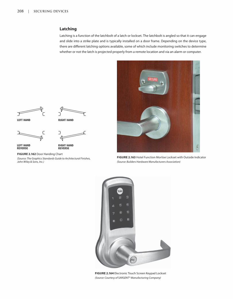
208 | SECURING DEVICES
c02.indd Page 208 03/03/2015 02:12:36:PM
FIGURE 2.162 Door Handing Chart
(Source: The Graphics Standards Guide to Architectural Finishes, John Wiley & Sons, Inc.)
FIGURE 2.163 Hotel Function Mortise Lockset with Outside Indicator
(Source: Builders Hardware Manufacturers Association)
FIGURE 2.164 Electronic Touch Screen Keypad Lockset
(Source: Courtesy of SARGENT® Manufacturing Company)
Latching
Latching is a function of the latchbolt of a latch or lockset. The latchbolt is angled so that it can engage
and slide into a strike plate and is typically installed on a door frame. Depending on the device type,
there are different latching options available, some of which include monitoring switches to determine
whether or not the latch is projected properly from a remote location and via an alarm or computer.
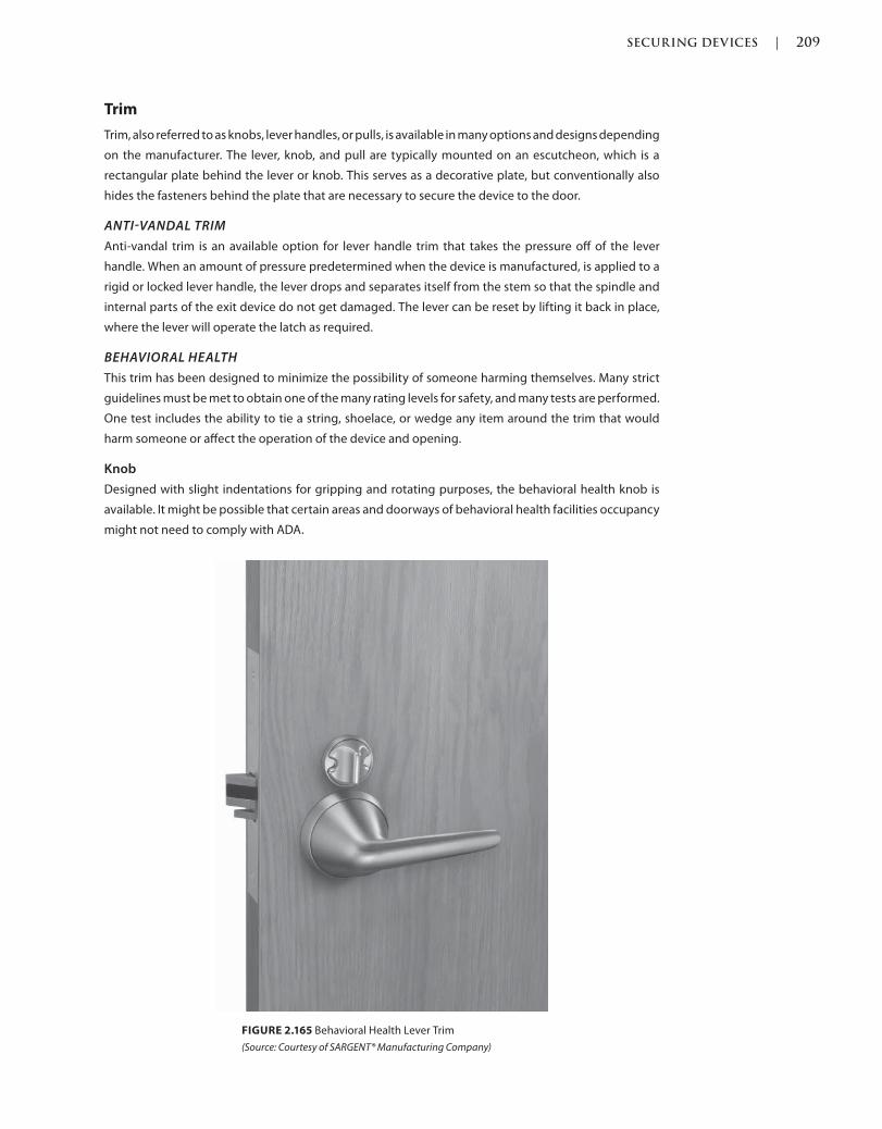
SECURING DEVICES | 209
c02.indd Page 209 03/03/2015 02:12:36:PM
Trim
Trim, also referred to as knobs, lever handles, or pulls, is available in many options and designs depending
on the manufacturer. The lever, knob, and pull are typically mounted on an escutcheon, which is a
rectangular plate behind the lever or knob. This serves as a decorative plate, but conventionally also
hides the fasteners behind the plate that are necessary to secure the device to the door.
ANTIVANDAL TRIM
Anti-vandal trim is an available option for lever handle trim that takes the pressure off of the lever
handle. When an amount of pressure predetermined when the device is manufactured, is applied to a
rigid or locked lever handle, the lever drops and separates itself from the stem so that the spindle and
internal parts of the exit device do not get damaged. The lever can be reset by lifting it back in place,
where the lever will operate the latch as required.
BEHAVIORAL HEALTH
This trim has been designed to minimize the possibility of someone harming themselves. Many strict
guidelines must be met to obtain one of the many rating levels for safety, and many tests are performed.
One test includes the ability to tie a string, shoelace, or wedge any item around the trim that would
harm someone or affect the operation of the device and opening.
Knob
Designed with slight indentations for gripping and rotating purposes, the behavioral health knob is
available. It might be possible that certain areas and doorways of behavioral health facilities occupancy
might not need to comply with ADA.
FIGURE 2.165 Behavioral Health Lever Trim
(Source: Courtesy of SARGENT® Manufacturing Company)
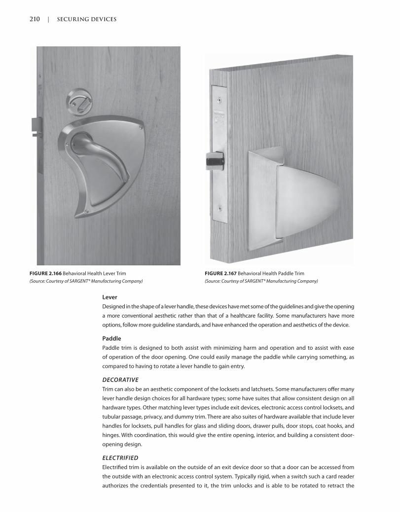
210 | SECURING DEVICES
c02.indd Page 210 03/03/2015 02:12:36:PM
Lever
Designed in the shape of a lever handle, these devices have met some of the guidelines and give the opening
a more conventional aesthetic rather than that of a healthcare facility. Some manufacturers have more
options, follow more guideline standards, and have enhanced the operation and aesthetics of the device.
Paddle
Paddle trim is designed to both assist with minimizing harm and operation and to assist with ease
of operation of the door opening. One could easily manage the paddle while carrying something, as
compared to having to rotate a lever handle to gain entry.
DECORATIVE
Trim can also be an aesthetic component of the locksets and latchsets. Some manufacturers offer many
lever handle design choices for all hardware types; some have suites that allow consistent design on all
hardware types. Other matching lever types include exit devices, electronic access control locksets, and
tubular passage, privacy, and dummy trim. There are also suites of hardware available that include lever
handles for locksets, pull handles for glass and sliding doors, drawer pulls, door stops, coat hooks, and
hinges. With coordination, this would give the entire opening, interior, and building a consistent door-
opening design.
ELECTRIFIED
Electrified trim is available on the outside of an exit device door so that a door can be accessed from
the outside with an electronic access control system. Typically rigid, when a switch such a card reader
authorizes the credentials presented to it, the trim unlocks and is able to be rotated to retract the
FIGURE 2.166 Behavioral Health Lever Trim
(Source: Courtesy of SARGENT® Manufacturing Company)
FIGURE 2.167 Behavioral Health Paddle Trim
(Source: Courtesy of SARGENT® Manufacturing Company)
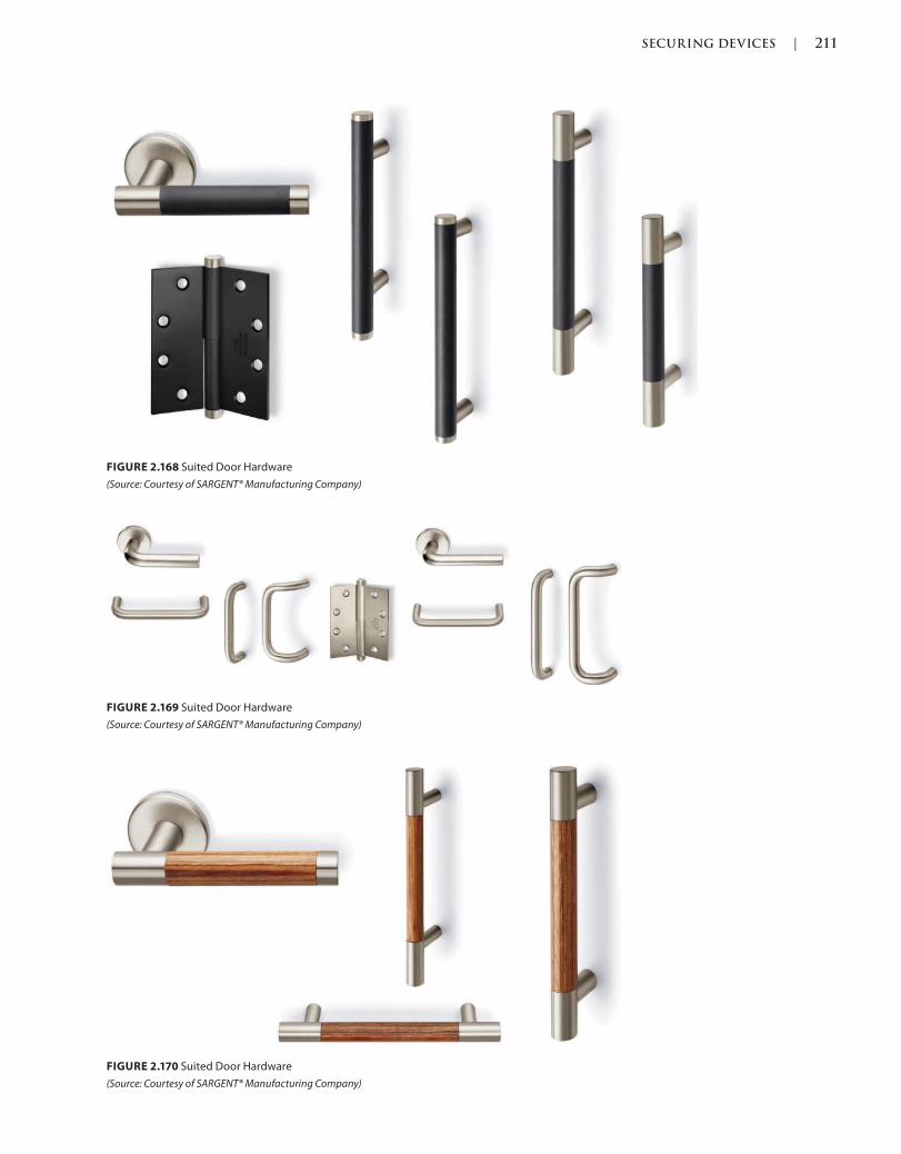
SECURING DEVICES | 211
c02.indd Page 211 03/03/2015 02:12:36:PM
FIGURE 2.170 Suited Door Hardware
(Source: Courtesy of SARGENT® Manufacturing Company)
FIGURE 2.168 Suited Door Hardware
(Source: Courtesy of SARGENT® Manufacturing Company)
FIGURE 2.169 Suited Door Hardware
(Source: Courtesy of SARGENT® Manufacturing Company)
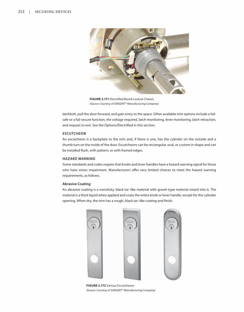
212 | SECURING DEVICES
c02.indd Page 212 03/03/2015 02:12:36:PM
latchbolt, pull the door forward, and gain entry to the space. Other available trim options include a fail-
safe or a fail-secure function, the voltage required, latch monitoring, lever monitoring, latch retraction,
and request to exit. See the Options/Electrified in this section.
ESCUTCHEON
An escutcheon is a backplate to the trim and, if there is one, has the cylinder on the outside and a
thumb turn on the inside of the door. Escutcheons can be rectangular, oval, or custom in shape and can
be installed flush, with pattern, or with framed edges.
HAZARD WARNING
Some standards and codes require that knobs and lever handles have a hazard warning signal for those
who have vision impairment. Manufacturers offer very limited choices to meet the hazard warning
requirements, as follows.
Abrasive Coating
An abrasive coating is a nonsticky, black tar–like material with gravel-type material mixed into it. The
material is a thick liquid when applied and coats the entire knob or lever handle, except for the cylinder
opening. When dry, the trim has a rough, black tar–like coating and finish.
FIGURE 2.171 Electrified Bored Lockset Chassis
(Source: Courtesy of SARGENT® Manufacturing Company)
FIGURE 2.172 Various Escutcheons
(Source: Courtesy of SARGENT® Manufacturing Company)
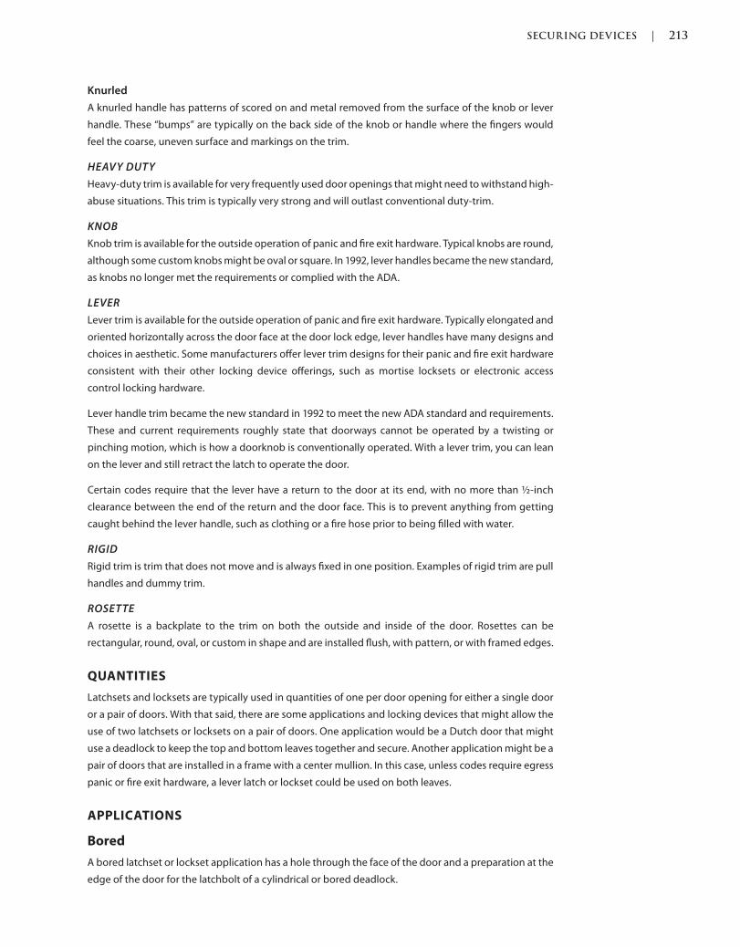
SECURING DEVICES | 213
c02.indd Page 213 03/03/2015 02:12:36:PM
Knurled
A knurled handle has patterns of scored on and metal removed from the surface of the knob or lever
handle. These “bumps” are typically on the back side of the knob or handle where the fingers would
feel the coarse, uneven surface and markings on the trim.
HEAVY DUTY
Heavy-duty trim is available for very frequently used door openings that might need to withstand high-
abuse situations. This trim is typically very strong and will outlast conventional duty-trim.
KNOB
Knob trim is available for the outside operation of panic and fire exit hardware. Typical knobs are round,
although some custom knobs might be oval or square. In 1992, lever handles became the new standard,
as knobs no longer met the requirements or complied with the ADA.
LEVER
Lever trim is available for the outside operation of panic and fire exit hardware. Typically elongated and
oriented horizontally across the door face at the door lock edge, lever handles have many designs and
choices in aesthetic. Some manufacturers offer lever trim designs for their panic and fire exit hardware
consistent with their other locking device offerings, such as mortise locksets or electronic access
control locking hardware.
Lever handle trim became the new standard in 1992 to meet the new ADA standard and requirements.
These and current requirements roughly state that doorways cannot be operated by a twisting or
pinching motion, which is how a doorknob is conventionally operated. With a lever trim, you can lean
on the lever and still retract the latch to operate the door.
Certain codes require that the lever have a return to the door at its end, with no more than ½-inch
clearance between the end of the return and the door face. This is to prevent anything from getting
caught behind the lever handle, such as clothing or a fire hose prior to being filled with water.
RIGID
Rigid trim is trim that does not move and is always fixed in one position. Examples of rigid trim are pull
handles and dummy trim.
ROSETTE
A rosette is a backplate to the trim on both the outside and inside of the door. Rosettes can be
rectangular, round, oval, or custom in shape and are installed flush, with pattern, or with framed edges.
QUANTITIES
Latchsets and locksets are typically used in quantities of one per door opening for either a single door
or a pair of doors. With that said, there are some applications and locking devices that might allow the
use of two latchsets or locksets on a pair of doors. One application would be a Dutch door that might
use a deadlock to keep the top and bottom leaves together and secure. Another application might be a
pair of doors that are installed in a frame with a center mullion. In this case, unless codes require egress
panic or fire exit hardware, a lever latch or lockset could be used on both leaves.
APPLICATIONS
Bored
A bored latchset or lockset application has a hole through the face of the door and a preparation at the
edge of the door for the latchbolt of a cylindrical or bored deadlock.
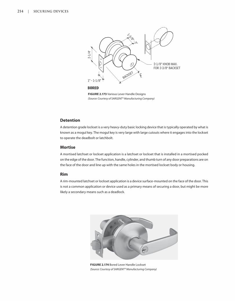
214 | SECURING DEVICES
c02.indd Page 214 03/03/2015 02:12:36:PM
FIGURE 2.173 Various Lever Handle Designs
(Source: Courtesy of SARGENT® Manufacturing Company)
FIGURE 2.174 Bored Lever Handle Lockset
(Source: Courtesy of SARGENT® Manufacturing Company)
Detention
A detention grade lockset is a very heavy-duty basic locking device that is typically operated by what is
known as a mogul key. The mogul key is very large with large cutouts where it engages into the lockset
to operate the deadbolt or latchbolt.
Mortise
A mortised latchset or lockset application is a latchset or lockset that is installed in a mortised pocked
on the edge of the door. The function, handle, cylinder, and thumb turn of any door preparations are on
the face of the door and line up with the same holes in the mortised lockset body or housing.
Rim
A rim-mounted latchset or lockset application is a device surface-mounted on the face of the door. This
is not a common application or device used as a primary means of securing a door, but might be more
likely a secondary means such as a deadlock.
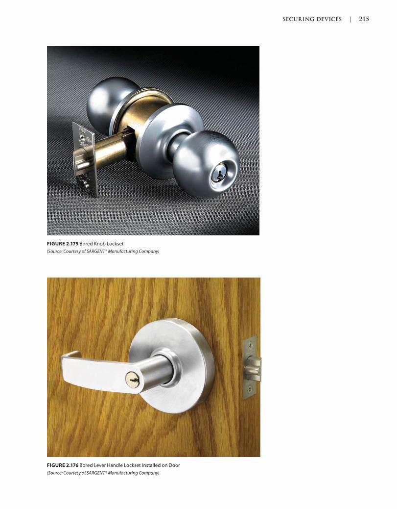
SECURING DEVICES | 215
c02.indd Page 215 03/03/2015 02:12:36:PM
FIGURE 2.175 Bored Knob Lockset
(Source: Courtesy of SARGENT® Manufacturing Company)
FIGURE 2.176 Bored Lever Handle Lockset Installed on Door
(Source: Courtesy of SARGENT® Manufacturing Company)
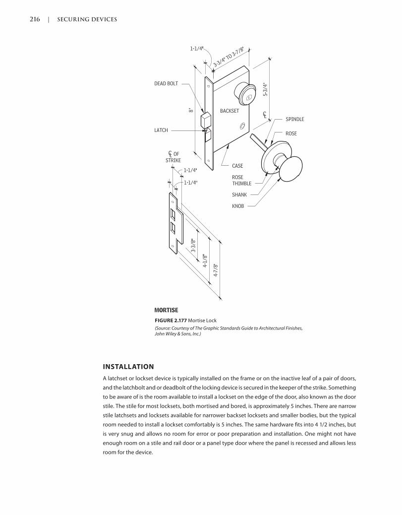
216 | SECURING DEVICES
c02.indd Page 216 03/03/2015 02:12:36:PM
INSTALLATION
A latchset or lockset device is typically installed on the frame or on the inactive leaf of a pair of doors,
and the latchbolt and or deadbolt of the locking device is secured in the keeper of the strike. Something
to be aware of is the room available to install a lockset on the edge of the door, also known as the door
stile. The stile for most locksets, both mortised and bored, is approximately 5 inches. There are narrow
stile latchsets and locksets available for narrower backset locksets and smaller bodies, but the typical
room needed to install a lockset comfortably is 5 inches. The same hardware fits into 4 1/2 inches, but
is very snug and allows no room for error or poor preparation and installation. One might not have
enough room on a stile and rail door or a panel type door where the panel is recessed and allows less
room for the device.
FIGURE 2.177 Mortise Lock
(Source: Courtesy of The Graphic Standards Guide to Architectural Finishes, John Wiley & Sons, Inc.)
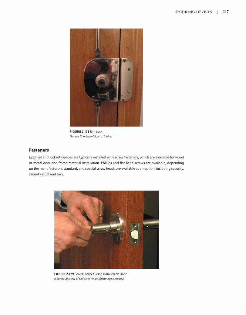
SECURING DEVICES | 217
c02.indd Page 217 03/03/2015 02:12:36:PM
Fasteners
Latchset and lockset devices are typically installed with screw fasteners, which are available for wood
or metal door and frame material installation. Phillips and flat-head screws are available, depending
on the manufacturer’s standard, and special screw heads are available as an option, including security,
security stud, and torx.
FIGURE 2.178 Rim Lock
(Source: Courtesy of Scott J. Tobias)
FIGURE 2.179 Bored Lockset Being Installed on Door
(Source: Courtesy of SARGENT® Manufacturing Company)
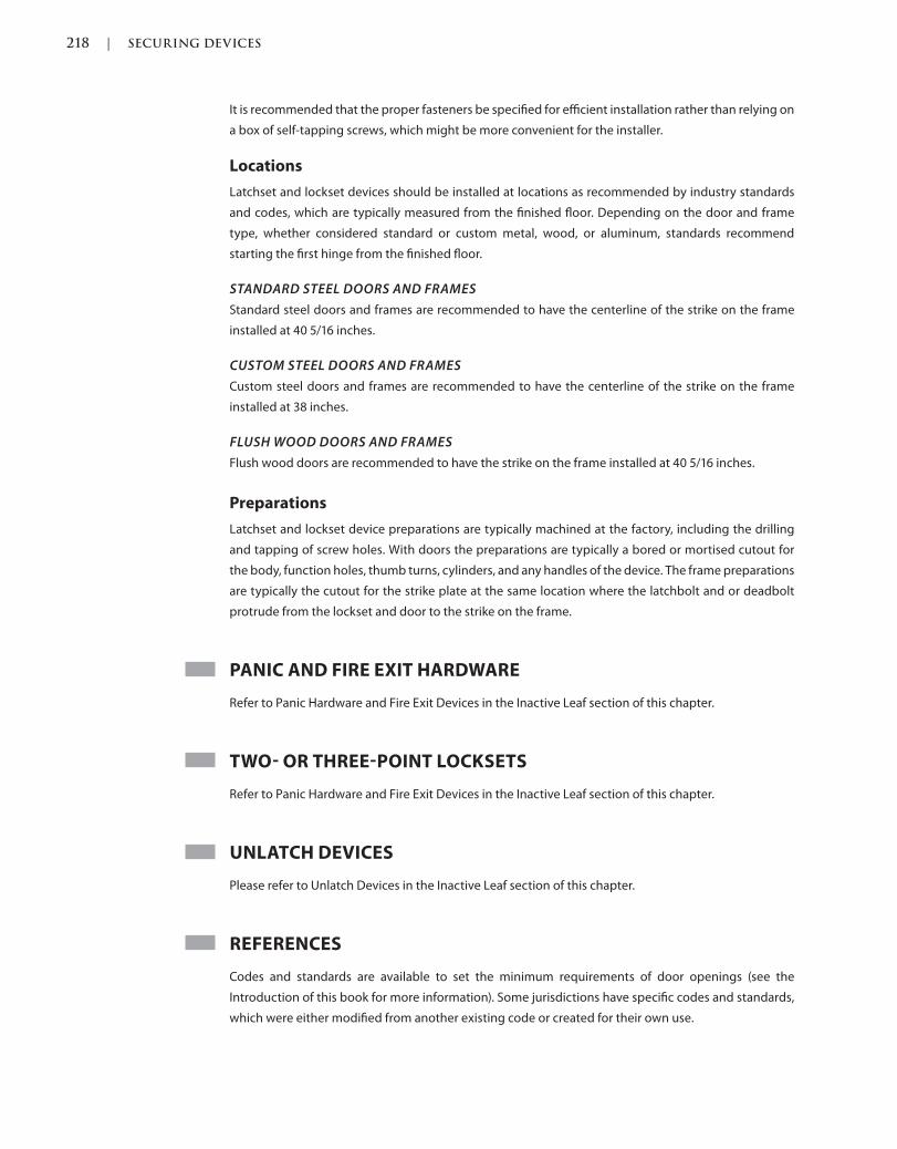
218 | SECURING DEVICES
c02.indd Page 218 03/03/2015 02:12:36:PM
It is recommended that the proper fasteners be specified for efficient installation rather than relying on
a box of self-tapping screws, which might be more convenient for the installer.
Locations
Latchset and lockset devices should be installed at locations as recommended by industry standards
and codes, which are typically measured from the finished floor. Depending on the door and frame
type, whether considered standard or custom metal, wood, or aluminum, standards recommend
starting the first hinge from the finished floor.
STANDARD STEEL DOORS AND FRAMES
Standard steel doors and frames are recommended to have the centerline of the strike on the frame
installed at 40 5/16 inches.
CUSTOM STEEL DOORS AND FRAMES
Custom steel doors and frames are recommended to have the centerline of the strike on the frame
installed at 38 inches.
FLUSH WOOD DOORS AND FRAMES
Flush wood doors are recommended to have the strike on the frame installed at 40 5/16 inches.
Preparations
Latchset and lockset device preparations are typically machined at the factory, including the drilling
and tapping of screw holes. With doors the preparations are typically a bored or mortised cutout for
the body, function holes, thumb turns, cylinders, and any handles of the device. The frame preparations
are typically the cutout for the strike plate at the same location where the latchbolt and or deadbolt
protrude from the lockset and door to the strike on the frame.
PANIC AND FIRE EXIT HARDWARE
Refer to Panic Hardware and Fire Exit Devices in the Inactive Leaf section of this chapter.
TWO OR THREEPOINT LOCKSETS
Refer to Panic Hardware and Fire Exit Devices in the Inactive Leaf section of this chapter.
UNLATCH DEVICES
Please refer to Unlatch Devices in the Inactive Leaf section of this chapter.
REFERENCES
Codes and standards are available to set the minimum requirements of door openings (see the
Introduction of this book for more information). Some jurisdictions have specific codes and standards,
which were either modified from another existing code or created for their own use.
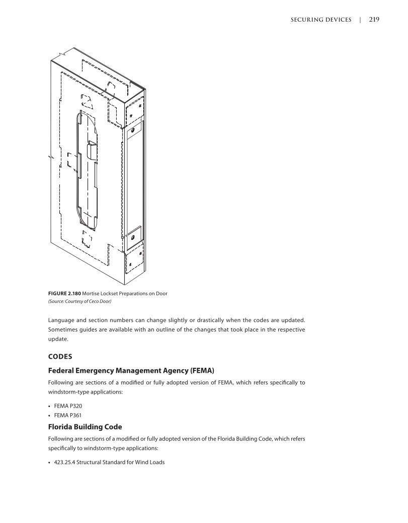
SECURING DEVICES | 219
c02.indd Page 219 03/03/2015 02:12:36:PM
FIGURE 2.180 Mortise Lockset Preparations on Door
(Source: Courtesy of Ceco Door)
Language and section numbers can change slightly or drastically when the codes are updated.
Sometimes guides are available with an outline of the changes that took place in the respective
update.
CODES
Federal Emergency Management Agency (FEMA)
Following are sections of a modified or fully adopted version of FEMA, which refers specifically to
windstorm-type applications:
FEMA P320
FEMA P361
Florida Building Code
Following are sections of a modified or fully adopted version of the Florida Building Code, which refers
specifically to windstorm-type applications:
423.25.4 Structural Standard for Wind Loads
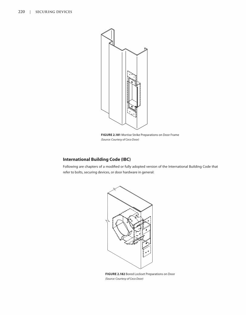
220 | SECURING DEVICES
c02.indd Page 220 03/03/2015 02:12:36:PM
FIGURE 2.182 Bored Lockset Preparations on Door
(Source: Courtesy of Ceco Door)
FIGURE 2.181 Mortise Strike Preparations on Door Frame
(Source: Courtesy of Ceco Door)
International Building Code (IBC)
Following are chapters of a modified or fully adopted version of the International Building Code that
refer to bolts, securing devices, or door hardware in general:
SECURING DEVICES | 221
c02.indd Page 221 03/03/2015 02:12:36:PM
Chapter 7: Fire and Smoke Protection Features
Chapter 10: Means of Egress
Section 1008 Doors, Gates and Turnstiles
Chapter 17: Special Inspections and Tests
International Code Council (ICC)/National Storm Shelter Association (NSSA)
500, Standard for the Design and Construction of Storm Shelters
The following are sections of a modified or fully adopted version of the ICC/NSSA 500 standard that
refer bolts, securing devices or door hardware in general:
501.5 Door Operation
806.3.2.2 Door Assemblies with Glazing, Sidelights, or Transoms for Hurricane Shelters
National Fire Protection Association (NFPA) 101: Life Safety Code
The following is a chapter of a modified or fully adopted version of the NFPA 101: Life Safety Code that
refers to bolts, securing devices or door hardware in general:
Chapter 7: Means of Egress
STANDARDS
ADA Accessibility Guidelines for Buildings and Facilities (ADAAG)
The following is a chapter of a modified or fully adopted version of the ADA Accessibility Guidelines for
Buildings and Facilities, that refers to bolts, securing devices, or door hardware in general:
Chapter 4: Accessible Routes
ASTM International (ASTM)
There are hundreds of ASTM International testing standards that are related to doors and door
hardware, from material and assembly testing to installation and application testing.
Door and Hardware Institute (DHI)
Following are technical documents available for reference that refer to bolts, securing devices, or door
hardware in general:
Abbreviations and Symbols
Basic Architectural Hardware
Hardware for Healthcare Facilities
Installation Guide for Doors and Hardware
Keying Systems and Nomenclature
Processing Hardware for Custom Aluminum Entrances
Recommended Locations for Builders’ Hardware Custom Steel Doors & Frames
Recommended Locations for Architectural Hardware for Standard Steel Doors & Frames
Recommended Locations for Architectural Hardware for Flush Wood Doors
Recommended Procedures for Processing Hardware Schedules and Templates
Sequence and Format for the Hardware Schedule
Tech-Talk ASD-1 Aluminum Storefront Doors
Tech-Talk EAH Electrified Architectural Hardware
Tech-Talk ED-1 Exit Devices
222 | SECURING DEVICES
c02.indd Page 222 03/03/2015 02:12:36:PM
Tech-Talk EL-1 Electromagnetic Locks
Tech-Talk HTL-92 Hotel/Motel Hardware and Keying
Tech-Talk MK-1 Masterkeying
Tech-Talk SP-1 Hardware Specification Writing
International Code Council A117.1 Accessible and Usable Buildings and
Facilities, (ICC)
Following is a chapter of a modified or fully adopted version of the ICC A117.1 Accessible and Usable
Buildings and Facilities that refers to bolts, securing devices, or door hardware in general:
Chapter 4: Accessible Routes
National Fire Protection Association (NFPA)
NFPA 70, the National Electric Code has a chapter that requires the use of panic or fire exit hardware
with an out-swinging door to protect the occupant of a certain sized room with a certain amount of
powered equipment in the room. This will help the occupant exit the space by allowing him to push
his body up against the device and door, allowing the door to unlatch and open. This might be in case
of an emergency or accident where the person could not operate a handle or something that requires
them to grab and turn it with their hands.
Chapter 3: Definitions
The following are sections of a modified or fully adopted version of NFPA 80: Standard for Fire Doors
and Other Opening Protectives, 2010 that refer to bolts, securing devices, or door hardware in general:
The following are chapters of a modified or fully adopted version of NFPA 80: Standard for Fire Doors
and Other Opening Protectives that refer to miscellaneous items or door hardware in general:
Chapter 5: Care and Maintenance
Chapter 6: Swinging Doors with Builders Hardware
Chapter 7: Swinging Doors with Fire Door Hardware
Chapter 8: Horizontally Sliding Doors
Chapter 9: Special-Purpose Horizontally Sliding Accordion or Folding Doors
Chapter 16: Access Doors
Chapter 19: Installation, Testing, and Maintenance of Fire Dampers
Annex A: Explanatory Material
The following is a chapter of a modified or fully adopted version of NFPA 105: Standard for Smoke
Door Assemblies and Other Opening Protectives that refers to miscellaneous items or door hardware
in general:
Chapter 6: Installation, Testing, and Maintenance of Smoke Dampers
The following is a chapter of a modified or fully adopted version of NFPA 252: Standard Method of Fire
Tests of Door Assemblies that refers to miscellaneous items or door hardware in general:
Chapter 5: Fire Door Assembly
Annex B: Commentary
SECURING DEVICES | 223
c02.indd Page 223 03/03/2015 02:12:36:PM
American National Standards Institute/Builders Hardware Manufacturers
Association (ANSI/BHMA)
The following are standards that refer to bolts, securing devices or door hardware in general:
ANSI/BHMA A156.2 American National Standard for Bored and Preassembled Locks and Latches
ANSI/BHMA A156.3 American National Standard for Exit Devices
ANSI/BHMA A156.5 American National Standard for Cylinders and Input Devices for Locks
ANSI/BHMA A156.9 American National Standard for Cabinet Hardware
ANSI/BHMA A156.11 American National Standard for Cabinet Locks
ANSI/BHMA A156.12 American National Standard for Interconnected Locks
ANSI/BHMA A156.13 American National Standard for Mortise Locks & Latches Series 1000
ANSI/BHMA A156.18 American National Standard for Materials and Finishes
ANSI/BHMA A156.23 American National Standard for Electromagnetic Locks
ANSI/BHMA A156.24 American National Standard for Delayed Egress Locking Systems
ANSI/BHMA A156.25 American National Standard for Electrified Locking Devices
ANSI/BHMA A156.28 American National Standard for Recommended Practices for Mechanical
Keying Systems
ANSI/BHMA A156.29 American National Standard for Exit Lock, Exit Alarms, Alarms for Exit Device
ANSI/BHMA A156.30 American National Standard for High Security Cylinders
ANSI/BHMA A156.31 American National Standard for Electric Strikes and Frame Mounted Actuators
ANSI/BHMA A156.32 American National Standard for Integrated Door Openings Assemblies
ANSI/BHMA A156.36 American National Standard for Auxiliary Locks
ANSI/BHMA A156.115 American National Standard for Hardware Preparation in Steel Doors and
Steel Frames
ANSI/BHMA A156.115W American National Standard for Hardware Preparation in Wood Doors with
Wood or Steel Frames
Underwriter Laboratories (UL)
The following are UL standards that affect securing devices:
UL 294—Access Control System Units

225
c03.indd Page 225 03/03/2015 12:7:6:PM
Now that we’ve hung and secured the door, the third part of the sequence is to specify operating trim.
Whether there is a locking device specified or not, such as a mortise lockset or panic hardware, next we
must specify or schedule a door pull, push plate, or a push-pull bar. There are many different manufac-
turers and variations of operating trim—there is something for just about everyone’s aesthetic taste.
With that said, if you want to create your own, some manufacturers have the ability to fabricate one’s
custom design or patterns into existing operating trim.
DOOR PULLS
Also Known As: Pulls, Pull Handles
DESCRIPTION
Door pulls are typically installed on doors that do not require latching or locking and are more for
simple function and or aesthetic appeal. There are manufacturers that have locking pull options, typi-
cally used on full glass door entrances.
PROPERTIES
Finishes
Door pulls are typically available in all architectural finishes to match the balance of hardware specified,
such as the hanging, securing, or controlling devices.
Grades
Door pulls are not categorized in grades but should comply with standards in Workmanship and Per-
formance Tests as described for Product Category J400 in the current version of ANSI/BHMA A156.6
American National Standard for Architectural Door Trim.
Operating Trim
3
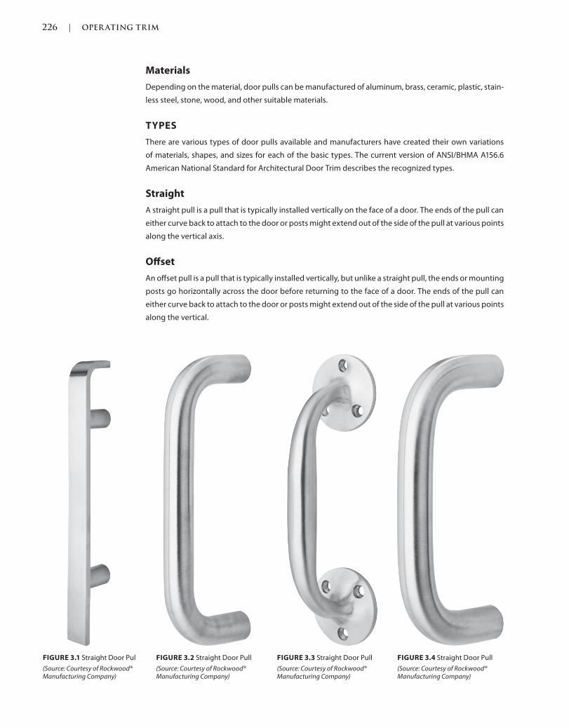
226 | OPER ATING TRIM
c03.indd Page 226 03/03/2015 12:7:6:PM
Materials
Depending on the material, door pulls can be manufactured of aluminum, brass, ceramic, plastic, stain-
less steel, stone, wood, and other suitable materials.
TYPES
There are various types of door pulls available and manufacturers have created their own variations
of materials, shapes, and sizes for each of the basic types. The current version of ANSI/BHMA A156.6
American National Standard for Architectural Door Trim describes the recognized types.
Straight
A straight pull is a pull that is typically installed vertically on the face of a door. The ends of the pull can
either curve back to attach to the door or posts might extend out of the side of the pull at various points
along the vertical axis.
Offset
An offset pull is a pull that is typically installed vertically, but unlike a straight pull, the ends or mounting
posts go horizontally across the door before returning to the face of a door. The ends of the pull can
either curve back to attach to the door or posts might extend out of the side of the pull at various points
along the vertical.
FIGURE 3.4 Straight Door Pull
(Source: Courtesy of Rockwood® Manufacturing Company)
FIGURE 3.1 Straight Door Pul
(Source: Courtesy of Rockwood® Manufacturing Company)
FIGURE 3.2 Straight Door Pull
(Source: Courtesy of Rockwood® Manufacturing Company)
FIGURE 3.3 Straight Door Pull
(Source: Courtesy of Rockwood® Manufacturing Company)
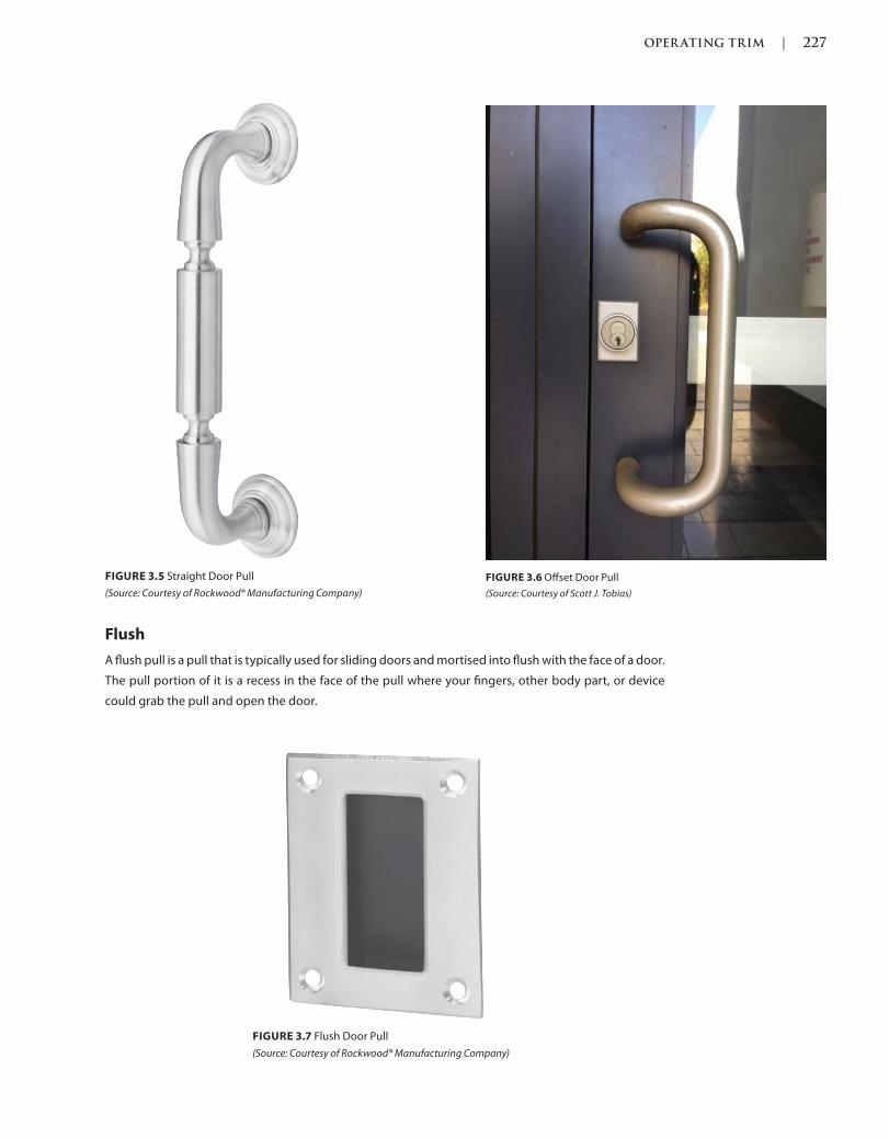
OPER ATING TRIM | 227
c03.indd Page 227 03/03/2015 12:7:6:PM
Flush
A flush pull is a pull that is typically used for sliding doors and mortised into flush with the face of a door.
The pull portion of it is a recess in the face of the pull where your fingers, other body part, or device
could grab the pull and open the door.
FIGURE 3.5 Straight Door Pull
(Source: Courtesy of Rockwood® Manufacturing Company)
FIGURE 3.6 Offset Door Pull
(Source: Courtesy of Scott J. Tobias)
FIGURE 3.7 Flush Door Pull
(Source: Courtesy of Rockwood® Manufacturing Company)
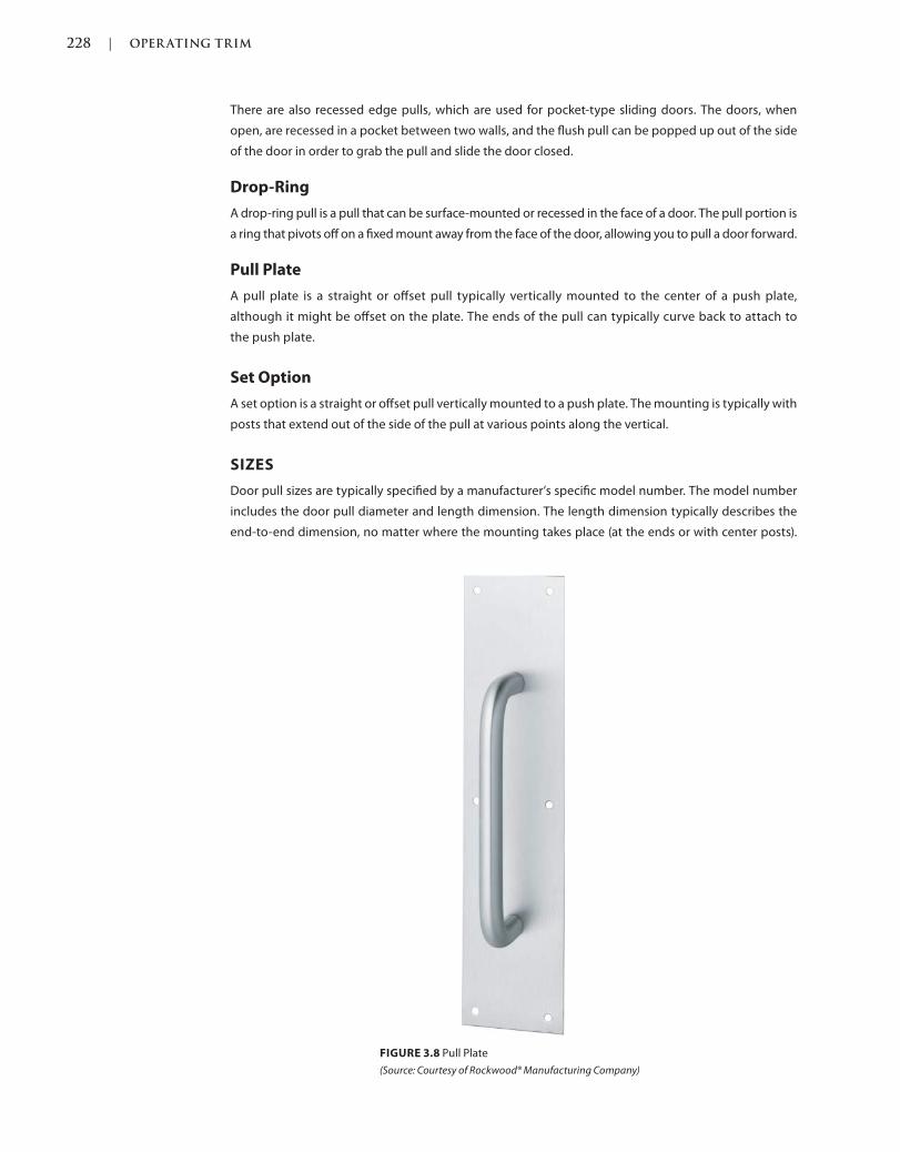
228 | OPER ATING TRIM
c03.indd Page 228 03/03/2015 12:7:6:PM
There are also recessed edge pulls, which are used for pocket-type sliding doors. The doors, when
open, are recessed in a pocket between two walls, and the flush pull can be popped up out of the side
of the door in order to grab the pull and slide the door closed.
Drop-Ring
A drop-ring pull is a pull that can be surface-mounted or recessed in the face of a door. The pull portion is
a ring that pivots off on a fixed mount away from the face of the door, allowing you to pull a door forward.
Pull Plate
A pull plate is a straight or offset pull typically vertically mounted to the center of a push plate,
although it might be offset on the plate. The ends of the pull can typically curve back to attach to
the push plate.
Set Option
A set option is a straight or offset pull vertically mounted to a push plate. The mounting is typically with
posts that extend out of the side of the pull at various points along the vertical.
SIZES
Door pull sizes are typically specified by a manufacturer’s specific model number. The model number
includes the door pull diameter and length dimension. The length dimension typically describes the
end-to-end dimension, no matter where the mounting takes place (at the ends or with center posts).
FIGURE 3.8 Pull Plate
(Source: Courtesy of Rockwood® Manufacturing Company)
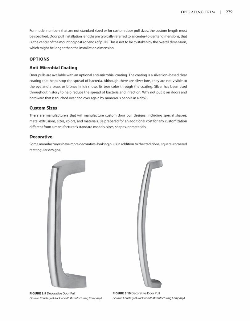
OPER ATING TRIM | 229
c03.indd Page 229 03/03/2015 12:7:6:PM
For model numbers that are not standard sized or for custom door pull sizes, the custom length must
be specified. Door pull installation lengths are typically referred to as center-to-center dimensions, that
is, the center of the mounting posts or ends of pulls. This is not to be mistaken by the overall dimension,
which might be longer than the installation dimension.
OPTIONS
Anti-Microbial Coating
Door pulls are available with an optional anti-microbial coating. The coating is a silver ion–based clear
coating that helps stop the spread of bacteria. Although there are silver ions, they are not visible to
the eye and a brass or bronze finish shows its true color through the coating. Silver has been used
throughout history to help reduce the spread of bacteria and infection: Why not put it on doors and
hardware that is touched over and over again by numerous people in a day?
Custom Sizes
There are manufacturers that will manufacture custom door pull designs, including special shapes,
metal extrusions, sizes, colors, and materials. Be prepared for an additional cost for any customization
different from a manufacturer’s standard models, sizes, shapes, or materials.
Decorative
Some manufacturers have more decorative-looking pulls in addition to the traditional square-cornered
rectangular designs.
FIGURE 3.10 Decorative Door Pull
(Source: Courtesy of Rockwood® Manufacturing Company)
FIGURE 3.9 Decorative Door Pull
(Source: Courtesy of Rockwood® Manufacturing Company)
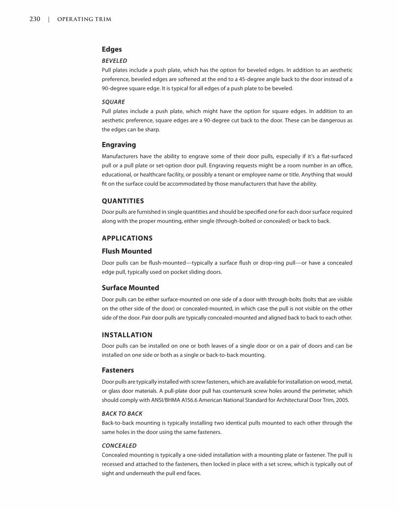
230 | OPER ATING TRIM
c03.indd Page 230 03/03/2015 12:7:6:PM
Edges
BEVELED
Pull plates include a push plate, which has the option for beveled edges. In addition to an aesthetic
preference, beveled edges are softened at the end to a 45-degree angle back to the door instead of a
90-degree square edge. It is typical for all edges of a push plate to be beveled.
SQUARE
Pull plates include a push plate, which might have the option for square edges. In addition to an
aesthetic preference, square edges are a 90-degree cut back to the door. These can be dangerous as
the edges can be sharp.
Engraving
Manufacturers have the ability to engrave some of their door pulls, especially if it’s a flat-surfaced
pull or a pull plate or set-option door pull. Engraving requests might be a room number in an office,
educational, or healthcare facility, or possibly a tenant or employee name or title. Anything that would
fit on the surface could be accommodated by those manufacturers that have the ability.
QUANTITIES
Door pulls are furnished in single quantities and should be specified one for each door surface required
along with the proper mounting, either single (through-bolted or concealed) or back to back.
APPLICATIONS
Flush Mounted
Door pulls can be flush-mounted—typically a surface flush or drop-ring pull—or have a concealed
edge pull, typically used on pocket sliding doors.
Surface Mounted
Door pulls can be either surface-mounted on one side of a door with through-bolts (bolts that are visible
on the other side of the door) or concealed-mounted, in which case the pull is not visible on the other
side of the door. Pair door pulls are typically concealed-mounted and aligned back to back to each other.
INSTALLATION
Door pulls can be installed on one or both leaves of a single door or on a pair of doors and can be
installed on one side or both as a single or back-to-back mounting.
Fasteners
Door pulls are typically installed with screw fasteners, which are available for installation on wood, metal,
or glass door materials. A pull-plate door pull has countersunk screw holes around the perimeter, which
should comply with ANSI/BHMA A156.6 American National Standard for Architectural Door Trim, 2005.
BACK TO BACK
Back-to-back mounting is typically installing two identical pulls mounted to each other through the
same holes in the door using the same fasteners.
CONCEALED
Concealed mounting is typically a one-sided installation with a mounting plate or fastener. The pull is
recessed and attached to the fasteners, then locked in place with a set screw, which is typically out of
sight and underneath the pull end faces.
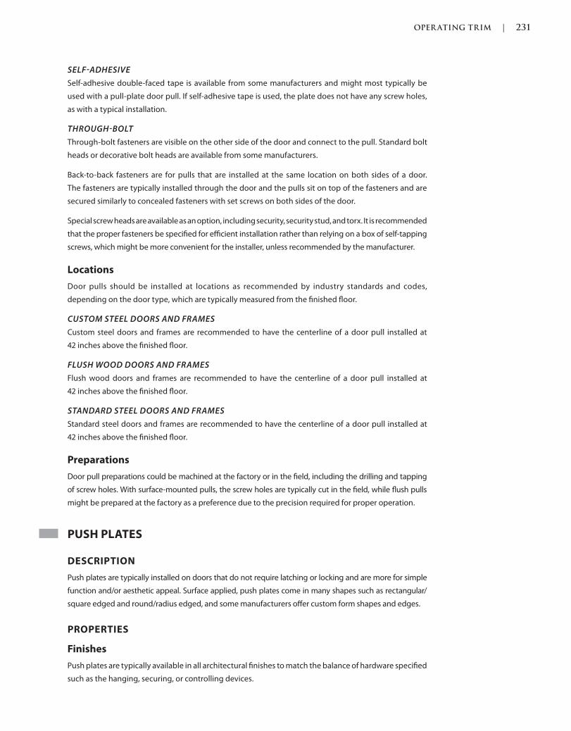
OPER ATING TRIM | 231
c03.indd Page 231 03/03/2015 12:7:6:PM
SELFADHESIVE
Self-adhesive double-faced tape is available from some manufacturers and might most typically be
used with a pull-plate door pull. If self-adhesive tape is used, the plate does not have any screw holes,
as with a typical installation.
THROUGHBOLT
Through-bolt fasteners are visible on the other side of the door and connect to the pull. Standard bolt
heads or decorative bolt heads are available from some manufacturers.
Back-to-back fasteners are for pulls that are installed at the same location on both sides of a door.
The fasteners are typically installed through the door and the pulls sit on top of the fasteners and are
secured similarly to concealed fasteners with set screws on both sides of the door.
Special screw heads are available as an option, including security, security stud, and torx. It is recommended
that the proper fasteners be specified for efficient installation rather than relying on a box of self-tapping
screws, which might be more convenient for the installer, unless recommended by the manufacturer.
Locations
Door pulls should be installed at locations as recommended by industry standards and codes,
depending on the door type, which are typically measured from the finished floor.
CUSTOM STEEL DOORS AND FRAMES
Custom steel doors and frames are recommended to have the centerline of a door pull installed at
42 inches above the finished floor.
FLUSH WOOD DOORS AND FRAMES
Flush wood doors and frames are recommended to have the centerline of a door pull installed at
42 inches above the finished floor.
STANDARD STEEL DOORS AND FRAMES
Standard steel doors and frames are recommended to have the centerline of a door pull installed at
42 inches above the finished floor.
Preparations
Door pull preparations could be machined at the factory or in the field, including the drilling and tapping
of screw holes. With surface-mounted pulls, the screw holes are typically cut in the field, while flush pulls
might be prepared at the factory as a preference due to the precision required for proper operation.
PUSH PLATES
DESCRIPTION
Push plates are typically installed on doors that do not require latching or locking and are more for simple
function and/or aesthetic appeal. Surface applied, push plates come in many shapes such as rectangular/
square edged and round/radius edged, and some manufacturers offer custom form shapes and edges.
PROPERTIES
Finishes
Push plates are typically available in all architectural finishes to match the balance of hardware specified
such as the hanging, securing, or controlling devices.
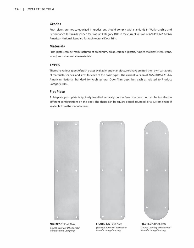
232 | OPER ATING TRIM
c03.indd Page 232 03/03/2015 12:7:6:PM
Grades
Push plates are not categorized in grades but should comply with standards in Workmanship and
Performance Tests as described for Product Category J400 in the current version of ANSI/BHMA A156.6
American National Standard for Architectural Door Trim.
Materials
Push plates can be manufactured of aluminum, brass, ceramic, plastic, rubber, stainless steel, stone,
wood, and other suitable materials.
TYPES
There are various types of push plates available, and manufacturers have created their own variations
of materials, shapes, and sizes for each of the basic types. The current version of ANSI/BHMA A156.6
American National Standard for Architectural Door Trim describes each as related to Product
Category J300.
Flat Plate
A flat-plate push plate is typically installed vertically on the face of a door but can be installed in
different configurations on the door. The shape can be square edged, rounded, or a custom shape if
available from the manufacturer.
FIGURE 3.11 Push Plate
(Source: Courtesy of Rockwood® Manufacturing Company)
FIGURE 3.12 Push Plate
(Source: Courtesy of Rockwood® Manufacturing Company)
FIGURE 3.13 Push Plate
(Source: Courtesy of Rockwood® Manufacturing Company)
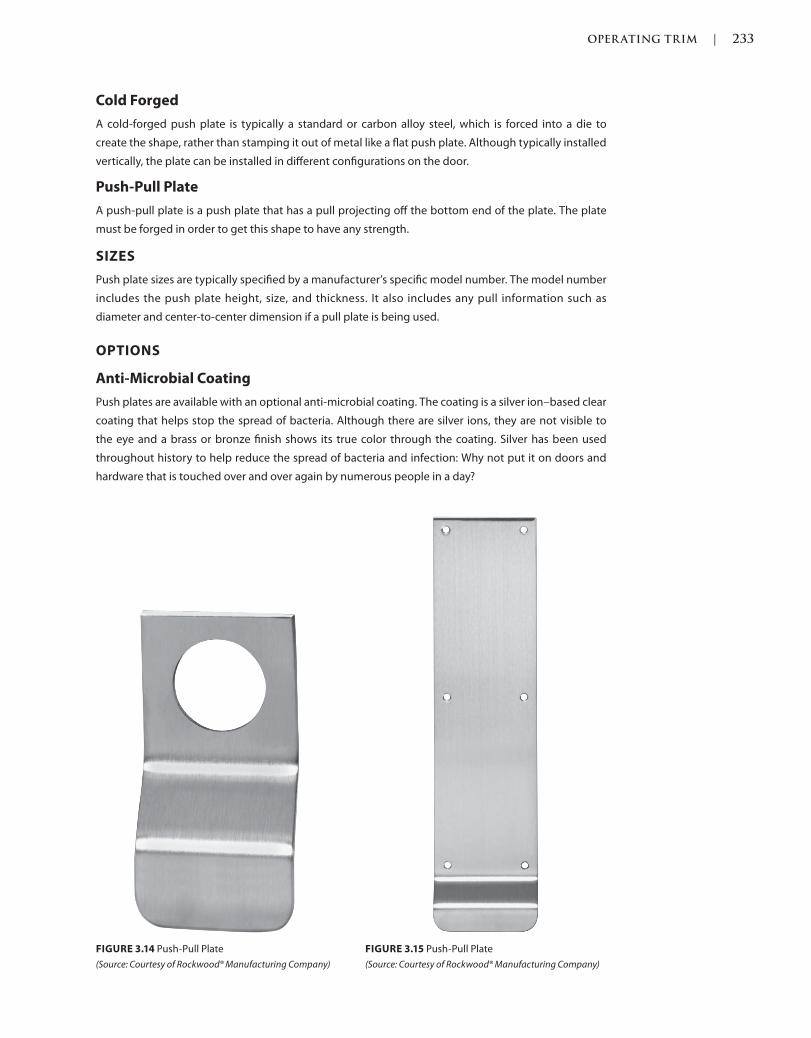
OPER ATING TRIM | 233
c03.indd Page 233 03/03/2015 12:7:6:PM
Cold Forged
A cold-forged push plate is typically a standard or carbon alloy steel, which is forced into a die to
create the shape, rather than stamping it out of metal like a flat push plate. Although typically installed
vertically, the plate can be installed in different configurations on the door.
Push-Pull Plate
A push-pull plate is a push plate that has a pull projecting off the bottom end of the plate. The plate
must be forged in order to get this shape to have any strength.
SIZES
Push plate sizes are typically specified by a manufacturer’s specific model number. The model number
includes the push plate height, size, and thickness. It also includes any pull information such as
diameter and center-to-center dimension if a pull plate is being used.
OPTIONS
Anti-Microbial Coating
Push plates are available with an optional anti-microbial coating. The coating is a silver ion–based clear
coating that helps stop the spread of bacteria. Although there are silver ions, they are not visible to
the eye and a brass or bronze finish shows its true color through the coating. Silver has been used
throughout history to help reduce the spread of bacteria and infection: Why not put it on doors and
hardware that is touched over and over again by numerous people in a day?
FIGURE 3.14 Push-Pull Plate
(Source: Courtesy of Rockwood® Manufacturing Company)
FIGURE 3.15 Push-Pull Plate
(Source: Courtesy of Rockwood® Manufacturing Company)
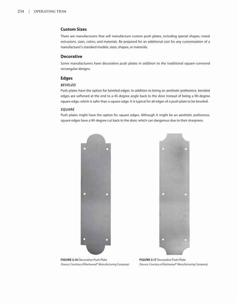
234 | OPER ATING TRIM
c03.indd Page 234 03/03/2015 12:7:6:PM
Custom Sizes
There are manufacturers that will manufacture custom push plates, including special shapes, metal
extrusions, sizes, colors, and materials. Be prepared for an additional cost for any customization of a
manufacturer’s standard models, sizes, shapes, or materials.
Decorative
Some manufacturers have decorative push plates in addition to the traditional square-cornered
rectangular designs.
Edges
BEVELED
Push plates have the option for beveled edges. In addition to being an aesthetic preference, beveled
edges are softened at the end to a 45-degree angle back to the door instead of being a 90-degree
square edge, which is safer than a square edge. It is typical for all edges of a push plate to be beveled.
SQUARE
Push plates might have the option for square edges. Although it might be an aesthetic preference,
square edges have a 90-degree cut back to the door, which can dangerous due to their sharpness.
FIGURE 3.16 Decorative Push Plate
(Source: Courtesy of Rockwood® Manufacturing Company)
FIGURE 3.17 Decorative Push Plate
(Source: Courtesy of Rockwood® Manufacturing Company)
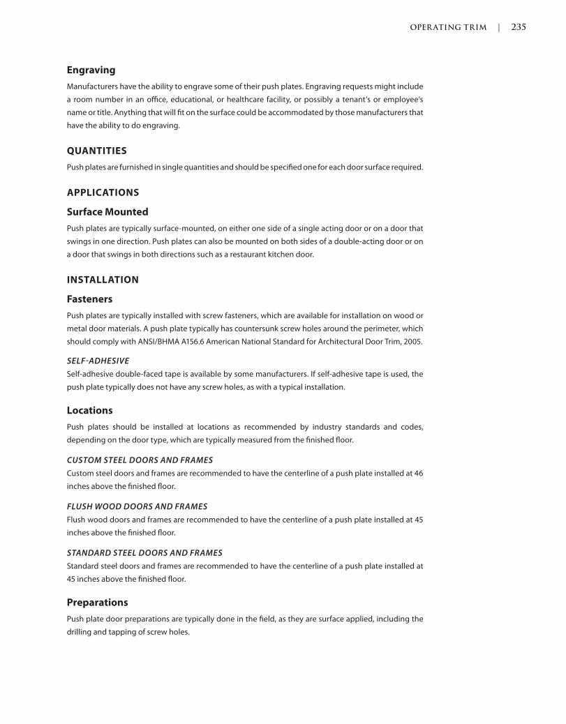
OPER ATING TRIM | 235
c03.indd Page 235 03/03/2015 12:7:6:PM
Engraving
Manufacturers have the ability to engrave some of their push plates. Engraving requests might include
a room number in an office, educational, or healthcare facility, or possibly a tenant’s or employee’s
name or title. Anything that will fit on the surface could be accommodated by those manufacturers that
have the ability to do engraving.
QUANTITIES
Push plates are furnished in single quantities and should be specified one for each door surface required.
APPLICATIONS
Surface Mounted
Push plates are typically surface-mounted, on either one side of a single acting door or on a door that
swings in one direction. Push plates can also be mounted on both sides of a double-acting door or on
a door that swings in both directions such as a restaurant kitchen door.
INSTALLATION
Fasteners
Push plates are typically installed with screw fasteners, which are available for installation on wood or
metal door materials. A push plate typically has countersunk screw holes around the perimeter, which
should comply with ANSI/BHMA A156.6 American National Standard for Architectural Door Trim, 2005.
SELFADHESIVE
Self-adhesive double-faced tape is available by some manufacturers. If self-adhesive tape is used, the
push plate typically does not have any screw holes, as with a typical installation.
Locations
Push plates should be installed at locations as recommended by industry standards and codes,
depending on the door type, which are typically measured from the finished floor.
CUSTOM STEEL DOORS AND FRAMES
Custom steel doors and frames are recommended to have the centerline of a push plate installed at 46
inches above the finished floor.
FLUSH WOOD DOORS AND FRAMES
Flush wood doors and frames are recommended to have the centerline of a push plate installed at 45
inches above the finished floor.
STANDARD STEEL DOORS AND FRAMES
Standard steel doors and frames are recommended to have the centerline of a push plate installed at
45 inches above the finished floor.
Preparations
Push plate door preparations are typically done in the field, as they are surface applied, including the
drilling and tapping of screw holes.
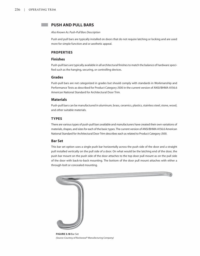
236 | OPER ATING TRIM
c03.indd Page 236 03/03/2015 12:7:6:PM
PUSH AND PULL BARS
Also Known As: Push-Pull Bars Description
Push and pull bars are typically installed on doors that do not require latching or locking and are used
more for simple function and or aesthetic appeal.
PROPERTIES
Finishes
Push-pull bars are typically available in all architectural finishes to match the balance of hardware speci-
fied such as the hanging, securing, or controlling devices.
Grades
Push-pull bars are not categorized in grades but should comply with standards in Workmanship and
Performance Tests as described for Product Category J500 in the current version of ANSI/BHMA A156.6
American National Standard for Architectural Door Trim.
Materials
Push-pull bars can be manufactured in aluminum, brass, ceramics, plastics, stainless steel, stone, wood,
and other suitable materials.
TYPES
There are various types of push-pull bars available and manufacturers have created their own variations of
materials, shapes, and sizes for each of the basic types. The current version of ANSI/BHMA A156.6 American
National Standard for Architectural Door Trim describes each as related to Product Category J500.
Bar Set
This bar set option uses a single push bar horizontally across the push side of the door and a straight
pull installed vertically on the pull side of a door. On what would be the latching end of the door, the
push bar mount on the push side of the door attaches to the top door pull mount as on the pull side
of the door with back-to-back mounting. The bottom of the door pull mount attaches with either a
through-bolt or concealed mounting.
FIGURE 3.18 Bar Set
(Source: Courtesy of Rockwood® Manufacturing Company)
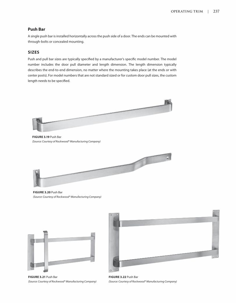
OPER ATING TRIM | 237
c03.indd Page 237 03/03/2015 12:7:6:PM
Push Bar
A single push bar is installed horizontally across the push side of a door. The ends can be mounted with
through-bolts or concealed mounting.
SIZES
Push and pull bar sizes are typically specified by a manufacturer’s specific model number. The model
number includes the door pull diameter and length dimension. The length dimension typically
describes the end-to-end dimension, no matter where the mounting takes place (at the ends or with
center posts). For model numbers that are not standard sized or for custom door pull sizes, the custom
length needs to be specified.
FIGURE 3.19 Push Bar
(Source: Courtesy of Rockwood® Manufacturing Company)
FIGURE 3.20 Push Bar
(Source: Courtesy of Rockwood® Manufacturing Company)
FIGURE 3.21 Push Bar
(Source: Courtesy of Rockwood® Manufacturing Company)
FIGURE 3.22 Push Bar
(Source: Courtesy of Rockwood® Manufacturing Company)
238 | OPER ATING TRIM
c03.indd Page 238 03/03/2015 12:7:6:PM
OPTIONS
Anti-Microbial Coating
Push and pull bars are available with an optional anti-microbial coating. The coating is a silver ion–
based clear coating that helps stop the spread of bacteria. Although there are silver ions, they are not
visible to the eye and a brass or bronze finish shows its true color through the coating. Silver has been
used throughout history to help reduce the spread of bacteria and infection: Why not put it on doors
and hardware that is touched over and over again by numerous different people in a day?
Custom Sizes
There are manufacturers that will manufacture custom push-pull bars, including special shapes, metal
extrusions, sizes, colors, and materials. Be prepared for an additional cost for any customization of a
manufacturer’s standard models, sizes, shapes, or materials.
Engraving
Manufacturers have the ability to engrave some of their push and pull bars, especially if they have a flat
surface. Engraving requests might be a room number in an office, educational, or healthcare facility, or
possibly a tenant’s or employee’s name or title. Anything that would fit on the surface can be accom-
modated by those manufacturers that have the ability to engrave.
QUANTITIES
Push-pull bars are furnished as a single push bar or in sets that include a push bar and door pull.
APPLICATIONS
Surface Mounted
Push and pull bars can be surface-mounted on the face of both sides of the door.
INSTALLATION
Push-pull bars can be installed as surface-mounted on the push side of a door or on both sides with a
door pull on the pull side of the door. A pair of doors has the same hardware on both leaves.
Fasteners
Push and pull bars are typically installed with screw fasteners, which are available for installation on
wood, metal, or glass doors.
BACK TO BACK
Back-to-back mounting can be used for the top bolt of the door pull, connected to the door swing side
of the push bar, in a bar set option installation.
CONCEALED
Concealed mounting can be used to install the bottom bolt of the door pull in a bar set option
installation.
THROUGHBOLT
Through-bolt mounting can be used to install the bottom bolt of the door pull, if it is a bar set option
installation. Decorative through-bolts might be available, depending on the manufacturer.
OPER ATING TRIM | 239
c03.indd Page 239 03/03/2015 12:7:6:PM
Locations
Push-pull bars should be installed at locations as recommended by industry standards and codes,
depending on the door type, which are typically measured from the finished floor.
CUSTOM STEEL DOORS AND FRAMES
Custom steel doors and frames are recommended to have the centerline of a push and pull bar installed
at 42 inches above the finished floor.
FLUSH WOOD DOORS AND FRAMES
Flush wood doors and frames are recommended to have the centerline of a door pull installed at 42
inches above the finished floor.
STANDARD STEEL DOORS AND FRAMES
Standard steel doors and frames are recommended to have the centerline of a door pull installed at 42
inches above the finished floor.
Preparations
Push and pull bar preparations can be machined at the factory but are more likely to be completed in
the field by the installer, including the drilling and tapping of screw holes.
REFERENCES
Codes and standards are available to set the minimum requirements of door openings (see the Intro-
duction of this book for more information). Some jurisdictions have specific codes and standards, which
were either modified from another existing code or created for their own use.
Language and section numbers can change slightly or drastically when the codes are updated. Look for
an outline, if available, of the changes that took place in the respective update.
CODES
International Building Code (IBC)
The following are chapters of a modified or fully adopted version of the International Building Code,
that refer to operating trim or door hardware in general:
Chapter 7: Fire and Smoke Protection Features
Chapter 10: Means of Egress
Chapter 17: Special Inspections and Tests
National Fire Protection Association (NFPA) 101: Life Safety Code
The following is a chapter of a modified or fully adopted version of the NFPA 101: Life Safety Code that
refers to operating trim or door hardware in general:
Chapter 7: Means of Egress
STANDARDS
ADA Accessibility Guidelines for Buildings and Facilities (ADAAG)
The following is a chapter of a modified or fully adopted version of the ADA Accessibility Guidelines for
Buildings and Facilities, that refers to operating trim or door hardware in general:
Chapter 4: Accessible Routes
240 | OPER ATING TRIM
c03.indd Page 240 03/03/2015 12:7:6:PM
ASTM International (ASTM)
There are hundreds of ASTM International testing standards that are related to doors and door
hardware, from material and assembly testing to installation and application testing.
Door and Hardware Institute (DHI)
The following are technical documents available for reference that refer to door push-pull bar or
operating trim in general:
Abbreviations and Symbols
Basic Architectural Hardware
Hardware for Healthcare Facilities
Installation Guide for Doors and Hardware
Processing Hardware for Custom Aluminum Entrances
Recommended Locations for Builders’ Hardware Custom Steel Doors & Frames
Recommended Locations for Architectural Hardware for Standard Steel Doors & Frames
Recommended Locations for Architectural Hardware for Flush Wood Doors
Recommended Procedures for Processing Hardware Schedules and Templates
Sequence and Format for the Hardware Schedule
Tech-Talk ASD-1 Aluminum Storefront Doors
Tech-Talk SP-1 Hardware Specification Writing
International Code Council A117.1 Accessible and Usable Buildings and
Facilities, (ICC)
The following is a chapter of a modified or fully adopted version of the ICC A117.1 Accessible and Usable
Buildings and Facilities that refers to operating trim or door hardware in general:
Chapter 4: Accessible Routes
National Fire Protection Association (NFPA)
The following are chapters of a modified or fully adopted version of NFPA 80: Standard for Fire Doors
and Other Opening Protectives that refer to operating trim or door hardware in general:
Chapter 5: Care and Maintenance
Chapter 6: Swinging Doors with Builders Hardware
Chapter 7: Swinging Doors with Fire Door Hardware
Chapter 8: Horizontally Sliding Doors
Chapter 9: Special-Purpose Horizontally Sliding Accordion or Folding Doors
Chapter 16: Access Doors
Chapter 19: Installation, Testing, and Maintenance of Fire Dampers
Annex A: Explanatory Material
The following is a chapter of a modified or fully adopted version of NFPA 105: Standard for Smoke Door
Assemblies and Other Opening Protectives that refers to operating trim or door hardware in general:
Chapter 6: Installation, Testing, and Maintenance of Smoke Dampers
The following is a chapter of a modified or fully adopted version of NFPA 252: Standard Method of Fire
Tests of Door Assemblies that refers to operating trim or door hardware in general:
Chapter 5: Fire Door Assembly
Annex B: Commentary
OPER ATING TRIM | 241
c03.indd Page 241 03/03/2015 12:7:6:PM
American National Standards Institute/Builders Hardware Manufacturers
Association (ANSI/BHMA)
The following are standards that refer to operating trim or door hardware in general:
ANSI/BHMA A156.6 American National Standard for Architectural Door Trim
ANSI/BHMA A156.18 American National Standard for Materials and Finishes
ANSI/BHMA A156.115 American National Standard for Preparation in Steel Door and Steel Frames
ANSI/BHMA A156.115W American National Standard for Preparation in Wood Doors with Wood or
Steel Frames

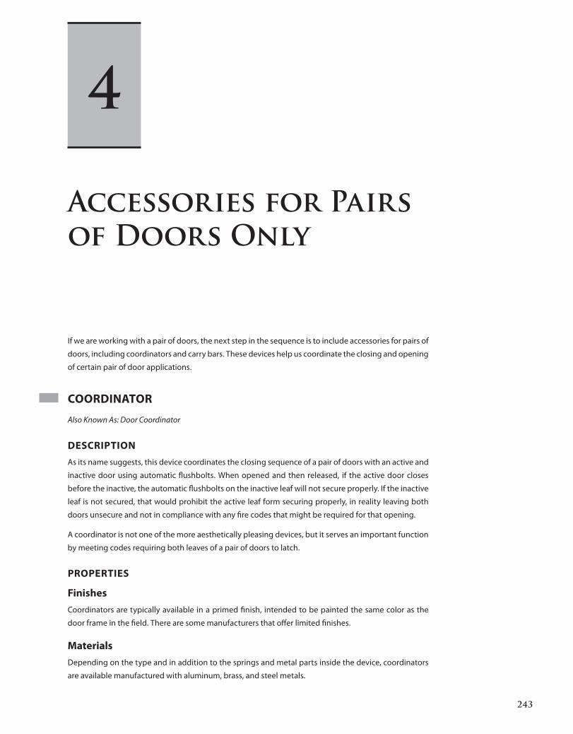
243
c04.indd 03/03/2015 01:4:10:PM Page 243Trim: 215 x 276 mm
Accessories for Pairs
of Doors Only
If we are working with a pair of doors, the next step in the sequence is to include accessories for pairs of
doors, including coordinators and carry bars. These devices help us coordinate the closing and opening
of certain pair of door applications.
COORDINATOR
Also Known As: Door Coordinator
DESCRIPTION
As its name suggests, this device coordinates the closing sequence of a pair of doors with an active and
inactive door using automatic flushbolts. When opened and then released, if the active door closes
before the inactive, the automatic flushbolts on the inactive leaf will not secure properly. If the inactive
leaf is not secured, that would prohibit the active leaf form securing properly, in reality leaving both
doors unsecure and not in compliance with any fire codes that might be required for that opening.
A coordinator is not one of the more aesthetically pleasing devices, but it serves an important function
by meeting codes requiring both leaves of a pair of doors to latch.
PROPERTIES
Finishes
Coordinators are typically available in a primed finish, intended to be painted the same color as the
door frame in the field. There are some manufacturers that offer limited finishes.
Materials
Depending on the type and in addition to the springs and metal parts inside the device, coordinators
are available manufactured with aluminum, brass, and steel metals.
4
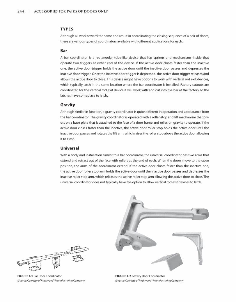
244 | ACCESSORIES FOR PAIRS OF DOORS ONLY
Trim: 215 x 276 mm c04.indd 03/03/2015 01:4:10:PM Page 244
TYPES
Although all work toward the same end result in coordinating the closing sequence of a pair of doors,
there are various types of coordinators available with different applications for each.
Bar
A bar coordinator is a rectangular tube-like device that has springs and mechanisms inside that
operate two triggers at either end of the device. If the active door closes faster than the inactive
one, the active door trigger holds the active door until the inactive door passes and depresses the
inactive door trigger. Once the inactive door trigger is depressed, the active door trigger releases and
allows the active door to close. This device might have options to work with vertical rod exit devices,
which typically latch in the same location where the bar coordinator is installed. Factory cutouts are
coordinated for the vertical rod exit device it will work with and cut into the bar at the factory so the
latches have someplace to latch.
Gravity
Although similar in function, a gravity coordinator is quite different in operation and appearance from
the bar coordinator. The gravity coordinator is operated with a roller-stop and lift mechanism that piv-
ots on a base plate that is attached to the face of a door frame and relies on gravity to operate. If the
active door closes faster than the inactive, the active door roller stop holds the active door until the
inactive door passes and rotates the lift arm, which raises the roller stop above the active door allowing
it to close.
Universal
With a body and installation similar to a bar coordinator, the universal coordinator has two arms that
extend and retract out of the face with rollers at the end of each. When the doors move to the open
position, the arms of the coordinator extend. If the active door closes faster than the inactive one,
the active door roller stop arm holds the active door until the inactive door passes and depresses the
inactive roller stop arm, which releases the active roller stop arm allowing the active door to close. The
universal coordinator does not typically have the option to allow vertical rod exit devices to latch.
FIGURE 4.1 Bar Door Coordinator
(Source: Courtesy of Rockwood® Manufacturing Company)
FIGURE 4.2 Gravity Door Coordinator
(Source: Courtesy of Rockwood® Manufacturing Company)
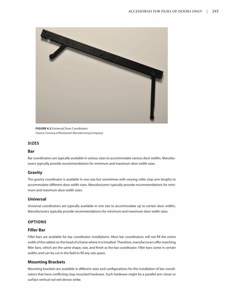
ACCESSORIES FOR PAIRS OF DOORS ONLY | 245
c04.indd 03/03/2015 01:4:10:PM Page 245Trim: 215 x 276 mm
SIZES
Bar
Bar coordinators are typically available in various sizes to accommodate various door widths. Manufac-
turers typically provide recommendations for minimum and maximum door width sizes.
Gravity
The gravity coordinator is available in one size but sometimes with varying roller stop arm lengths to
accommodate different door width sizes. Manufacturers typically provide recommendations for mini-
mum and maximum door width sizes.
Universal
Universal coordinators are typically available in one size to accommodate up to certain door widths.
Manufacturers typically provide recommendations for minimum and maximum door width sizes.
OPTIONS
Filler Bar
Filler bars are available for bar coordinator installations. Most bar coordinators will not fill the entire
width of the rabbet on the head of a frame where it is installed. Therefore, manufacturers offer matching
filler bars, which are the same shape, size, and finish as the bar coordinator. Filler bars come in certain
widths and can be cut in the field to fill any size space.
Mounting Brackets
Mounting brackets are available in different sizes and configurations for the installation of bar coordi-
nators that have conflicting stop mounted hardware. Such hardware might be a parallel arm closer or
surface vertical rod exit device strike.
FIGURE 4.3 Universal Door Coordinator
(Source: Courtesy of Rockwood® Manufacturing Company)
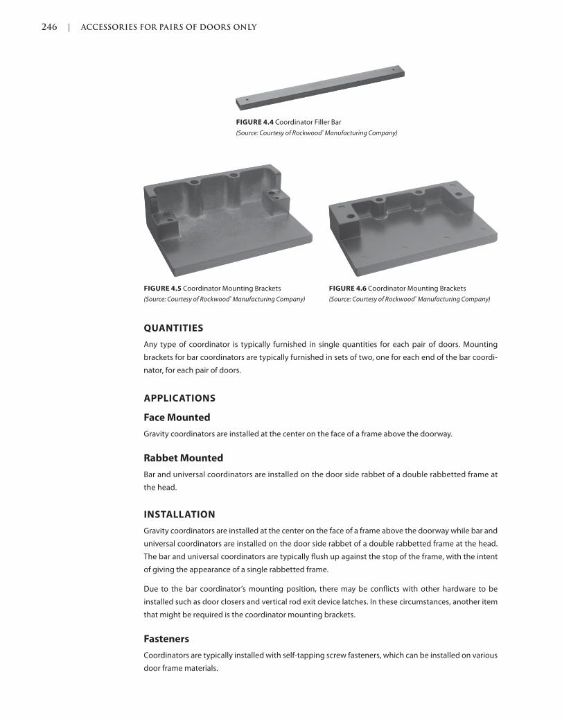
246 | ACCESSORIES FOR PAIRS OF DOORS ONLY
Trim: 215 x 276 mm c04.indd 03/03/2015 01:4:10:PM Page 246
QUANTITIES
Any type of coordinator is typically furnished in single quantities for each pair of doors. Mounting
brackets for bar coordinators are typically furnished in sets of two, one for each end of the bar coordi-
nator, for each pair of doors.
APPLICATIONS
Face Mounted
Gravity coordinators are installed at the center on the face of a frame above the doorway.
Rabbet Mounted
Bar and universal coordinators are installed on the door side rabbet of a double rabbetted frame at
the head.
INSTALLATION
Gravity coordinators are installed at the center on the face of a frame above the doorway while bar and
universal coordinators are installed on the door side rabbet of a double rabbetted frame at the head.
The bar and universal coordinators are typically flush up against the stop of the frame, with the intent
of giving the appearance of a single rabbetted frame.
Due to the bar coordinator’s mounting position, there may be conflicts with other hardware to be
installed such as door closers and vertical rod exit device latches. In these circumstances, another item
that might be required is the coordinator mounting brackets.
Fasteners
Coordinators are typically installed with self-tapping screw fasteners, which can be installed on various
door frame materials.
FIGURE 4.4 Coordinator Filler Bar
(Source: Courtesy of Rockwood® Manufacturing Company)
FIGURE 4.5 Coordinator Mounting Brackets
(Source: Courtesy of Rockwood® Manufacturing Company)
FIGURE 4.6 Coordinator Mounting Brackets
(Source: Courtesy of Rockwood® Manufacturing Company)
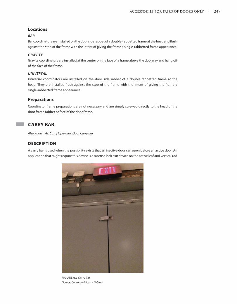
ACCESSORIES FOR PAIRS OF DOORS ONLY | 247
c04.indd 03/03/2015 01:4:10:PM Page 247Trim: 215 x 276 mm
Locations
BAR
Bar coordinators are installed on the door side rabbet of a double-rabbetted frame at the head and flush
against the stop of the frame with the intent of giving the frame a single-rabbetted frame appearance.
GRAVITY
Gravity coordinators are installed at the center on the face of a frame above the doorway and hang off
of the face of the frame.
UNIVERSAL
Universal coordinators are installed on the door side rabbet of a double-rabbetted frame at the
head. They are installed flush against the stop of the frame with the intent of giving the frame a
single-rabbetted frame appearance.
Preparations
Coordinator frame preparations are not necessary and are simply screwed directly to the head of the
door frame rabbet or face of the door frame.
CARRY BAR
Also Known As: Carry Open Bar, Door Carry Bar
DESCRIPTION
A carry bar is used when the possibility exists that an inactive door can open before an active door. An
application that might require this device is a mortise lock exit device on the active leaf and vertical rod
FIGURE 4.7 Carry Bar
(Source: Courtesy of Scott J. Tobias)
248 | ACCESSORIES FOR PAIRS OF DOORS ONLY
Trim: 215 x 276 mm c04.indd 03/03/2015 01:4:10:PM Page 248
exit device on the inactive one. If the vertical rod exit device door is opened first, the carry bar pushes
the active door out far enough so that it can engage with the coordinator and for a proper closing
sequence. If the vertical rod exit device door does not close first, the mortise lock exit device door will
not latch properly, prohibiting both leaves from latching at all.
PROPERTIES
Finishes
Coordinators are typically available with limited architectural finishes, most of the time available with a
gray prime coat for painting in the field, typically with the same color as the door and frame.
Materials
Depending on the manufacturer, carry bars are available manufactured with brass and steel metals and
some with nylon rollers to assist with the opening of the active door.
TYPES
Although they are manufactured slightly differently, there is really only one type of carry bar. Most are
manufactured out of a metal that is fixed to the inactive door, with either a metal or nylon roller at the
other end, which are used to assist with the opening of the active door.
SIZES
Carry bars are very small, no more than 2 inches by 3 inches on either side.
OPTIONS
Adjustment
The only option available for some carry bars is an adjustment to the length of the arm. The adjustment
allows for use with various door sizes and gives the device an extra 1/2 inch extension if necessary.
QUANTITIES
Carry bars are typically furnished in single quantities for each pair of doors.
APPLICATIONS
Surface Mounted
Carry bars are surface-mounted on the push side face of the inactive door.
INSTALLATION
Fasteners
Carry bars are typically installed with through-bolts in order to give the device a more secure installa-
tion to the face of the door.
Locations
Carry bars are typically located on the push side and near the top edge of the inactive leaf of a pair
of doors.
ACCESSORIES FOR PAIRS OF DOORS ONLY | 249
c04.indd 03/03/2015 01:4:10:PM Page 249Trim: 215 x 276 mm
Preparations
Carry bar preparations are not necessary and they are simply through-bolted to the edge the active
door of a pair of doors in the field.
SUBSTITUTIONS
If product substitution requests are allowed for door hardware, it is typically specified in Division 1 of
the project specifications. The substitution request requirements typically request product data and
proof that the requested substitute will meet the same grade, function, application, aesthetic, and
quality of the originally specified product.
Sometimes, to be more competitive on a bid, a less durable or lower-quality carry bar substitution
might be offered or take place without much or any knowledge at all. A cost credit might be offered,
and sometimes it might not be when the lesser quality substitution takes place. A lesser quality carry
bar substitution might result in the failure of the installation, causing a necessary replacement of the
product. This is also less sustainable since more parts are needed more frequently due to the premature
replacement.
REFERENCES
Codes and standards are available to set the minimum requirements of door openings (see the Intro-
duction of this book for more information). Some jurisdictions have specific codes and standards, which
were either modified from another existing code or created for their own use.
Language and section numbers can change slightly or drastically when the codes are updated. Look for
an outline, if available, of the changes that took place in the respective update.
CODES
International Building Code (IBC)
The following are chapters of a modified or fully adopted version of the International Building Code
that refer to accessories for pairs of doors or door hardware in general:
Chapter 7: Fire and Smoke Protection Features
Chapter 10: Means of Egress
National Fire Protection Association (NFPA) 101: Life Safety Code
The following is a chapter of a modified or fully adopted version of the NFPA 101: Life Safety Code,
which refers to accessories for pairs of doors or door hardware in general:
Chapter 7 Means of Egress
STANDARDS
ADA Accessibility Guidelines for Buildings and Facilities (ADAAG)
The following is a chapter of a modified or fully adopted version of the ADA Accessibility Guidelines
for Buildings and Facilities, which refers to accessories for pairs of doors or door hardware in general:
Chapter 4: Accessible Routes

250 | ACCESSORIES FOR PAIRS OF DOORS ONLY
Trim: 215 x 276 mm c04.indd 03/03/2015 01:4:10:PM Page 250
ASTM International (ASTM)
There are hundreds of ASTM International testing standards that are related to doors and door hard-
ware, from material and assembly testing to installation and application testing.
Door and Hardware Institute (DHI)
The following are technical documents available for reference that refer to accessories for pairs of doors
or door hardware in general:
Abbreviations and Symbols
Basic Architectural Hardware
Hardware for Healthcare Facilities
Installation Guide for Doors and Hardware
Processing Hardware for Custom Aluminum Entrances
Recommended Locations for Builders’ Hardware Custom Steel Doors & Frames
Recommended Locations for Architectural Hardware for Standard Steel Doors & Frames
Recommended Locations for Architectural Hardware for Flush Wood Doors
Recommended Procedures for Processing Hardware Schedules and Templates
Sequence and Format for the Hardware Schedule
Tech-Talk ASD-1 Aluminum Storefront Doors
Tech-Talk SP-1 Hardware Specification Writing
International Code Council A117.1 Accessible and Usable
Buildings and Facilities, (ICC)
The following is a chapter of a modified or fully adopted version of the ICC A117.1 Accessible and Usable
Buildings and Facilities, which refers to accessories for pairs of doors or door hardware in general:
Chapter 4: Accessible Routes
National Fire Protection Association (NFPA)
The following are chapters of a modified or fully adopted version of NFPA 80: Standard for Fire
Doors and Other Opening Protectives, which refer to accessories for pairs of doors or door hard-
ware in general:
Chapter 5: Care and Maintenance
Chapter 6: Swinging Doors with Builders Hardware
Chapter 7: Swinging Doors with Fire Door Hardware
Chapter 8: Horizontally Sliding Doors
Chapter 9: Special-Purpose Horizontally Sliding Accordion or Folding Doors
Chapter 16: Access Doors
Chapter 19: Installation, Testing, and Maintenance of Fire Dampers
Annex A: Explanatory Material
The following is a chapter of a modified or fully adopted version of NFPA 105: Standard for Smoke Door
Assemblies and Other Opening Protectives, which refers to miscellaneous items or door hardware in
general:
Chapter 6: Installation, Testing, and Maintenance of Smoke Dampers

ACCESSORIES FOR PAIRS OF DOORS ONLY | 251
c04.indd 03/03/2015 01:4:10:PM Page 251Trim: 215 x 276 mm
The following is a chapter of a modified or fully adopted version of NFPA 252: Standard Method of Fire
Tests of Door Assemblies, which refers to miscellaneous items or door hardware in general:
Chapter 5: Fire Door Assembly
Annex B: Commentary
American National Standards Institute/Builders Hardware Manufacturers
Association (ANSI/BHMA)
The following are standards that refer to accessories for pairs of doors or door hardware in general:
ANSI/BHMA A156.18 American National Standard for Materials and Finishes

253
c05.indd Page 253 03/03/2015 03:59:0:PM
Closing and controlling a door is important for many reasons, including the protection of lives and
materials, traffic control, security, and energy efficiency.
A closing device, also known as a door closer, is manufactured as different types of fixtures, depending
on the function and application of the opening. Surface-mounted, concealed overhead in the door or
frame, and concealed in the floor versions are available for different applications with various options
for each.
A controlling device, also known as a door stop, is also manufactured as different types of mechanisms,
including floor, wall, and overhead, in order to protect the door, frame, hardware, and surrounding con-
ditions. Sometimes a closing device is erroneously used as a controlling device, which it is not intended
to be. Misusing the closing device shortens the life of the opening because of having to maintain and
adjust the door, frame, and hardware time and time again.
Depending on the local codes and authority having jurisdiction, some door openings might have cer-
tain considerations in regard to their closing requirements if there are sprinklers installed on either side
of the opening.
DOOR CLOSER
Also Known As: Closing Device, Closer
DESCRIPTION
A door closer is intended to close a door automatically after it has been opened. This is a manual device
that works with springs and or hydraulic fluid to create the proper tension and pressure to close the
door as intended. A door might need to close for numerous reasons, such as for security purposes,
because of fire protection codes, for energy efficiency, or simply as a preference. With that said, door
closers have many options, one of which is the ability to manually hold the door in the open position,
Closing and Control
Devices
5
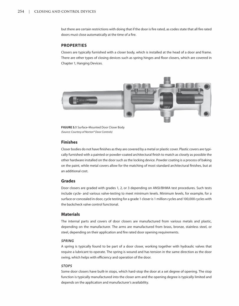
254 | CLOSING AND CONTROL DEVICES
c05.indd Page 254 03/03/2015 03:59:0:PM
but there are certain restrictions with doing that if the door is fire rated, as codes state that all fire rated
doors must close automatically at the time of a fire.
PROPERTIES
Closers are typically furnished with a closer body, which is installed at the head of a door and frame.
There are other types of closing devices such as spring hinges and floor closers, which are covered in
Chapter 1, Hanging Devices.
Finishes
Closer bodies do not have finishes as they are covered by a metal or plastic cover. Plastic covers are typi-
cally furnished with a painted or powder-coated architectural finish to match as closely as possible the
other hardware installed on the door such as the locking device. Powder coating is a process of baking
on the paint, while metal covers allow for the matching of most standard architectural finishes, but at
an additional cost.
Grades
Door closers are graded with grades 1, 2, or 3 depending on ANSI/BHMA test procedures. Such tests
include cycle- and various valve-testing to meet minimum levels. Minimum levels, for example, for a
surface or concealed in door, cycle testing for a grade 1 closer is 1 million cycles and 100,000 cycles with
the backcheck valve control functional.
Materials
The internal parts and covers of door closers are manufactured from various metals and plastic,
depending on the manufacturer. The arms are manufactured from brass, bronze, stainless steel, or
steel, depending on their application and fire rated door opening requirements.
SPRING
A spring is typically found to be part of a door closer, working together with hydraulic valves that
require a lubricant to operate. The spring is wound and has tension in the same direction as the door
swing, which helps with efficiency and operation of the door.
STOPS
Some door closers have built-in stops, which hard-stop the door at a set degree of opening. The stop
function is typically manufactured into the closer arm and the opening degree is typically limited and
depends on the application and manufacturer’s availability.
FIGURE 5.1 Surface-Mounted Door Closer Body
(Source: Courtesy of Norton® Door Controls)
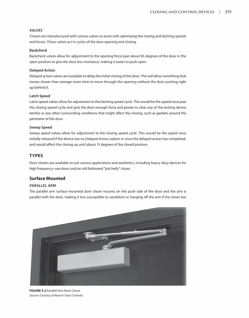
CLOSING AND CONTROL DEVICES | 255
c05.indd Page 255 03/03/2015 03:59:0:PM
VALVES
Closers are manufactured with various valves to assist with optimizing the closing and latching speeds
and forces. These valves act in cycles of the door opening and closing.
Backcheck
Backcheck valves allow for adjustment to the opening force past about 65 degrees of the door in the
open position to give the door less resistance, making it easier to push open.
Delayed Action
Delayed action valves are available to delay the initial closing of the door. This will allow something that
moves slower than average more time to move through the opening without the door pushing right
up behind it.
Latch Speed
Latch speed valves allow for adjustment to the latching speed cycle. This would be the speed once past
the closing speed cycle and give the door enough force and power to clear any of the locking device
latches or any other surrounding conditions that might affect the closing, such as gaskets around the
perimeter of the door.
Sweep Speed
Sweep speed valves allow for adjustment to the closing speed cycle. This would be the speed once
initially released if the device has no Delayed Action option or once the delayed action has completed,
and would affect the closing up until about 15 degrees of the closed position.
TYPES
Door closers are available to suit various applications and aesthetics, including heavy-duty devices for
high frequency–use doors and an old fashioned “pot belly” closer.
Surface Mounted
PARALLEL ARM
The parallel arm surface-mounted door closer mounts on the push side of the door and the arm is
parallel with the door, making it less susceptible to vandalism or hanging off the arm if the closer has
FIGURE 5.2 Parallel Arm Door Closer
(Source: Courtesy of Norton® Door Controls)
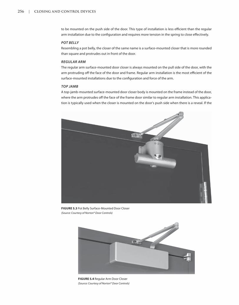
256 | CLOSING AND CONTROL DEVICES
c05.indd Page 256 03/03/2015 03:59:0:PM
to be mounted on the push side of the door. This type of installation is less efficient than the regular
arm installation due to the configuration and requires more tension in the spring to close effectively.
POT BELLY
Resembling a pot belly, the closer of the same name is a surface-mounted closer that is more rounded
than square and protrudes out in front of the door.
REGULAR ARM
The regular arm surface-mounted door closer is always mounted on the pull side of the door, with the
arm protruding off the face of the door and frame. Regular arm installation is the most efficient of the
surface-mounted installations due to the configuration and force of the arm.
TOP JAMB
A top-jamb-mounted surface-mounted door closer body is mounted on the frame instead of the door,
where the arm protrudes off the face of the frame door similar to regular arm installation. This applica-
tion is typically used when the closer is mounted on the door’s push side when there is a reveal. If the
FIGURE 5.3 Pot Belly Surface-Mounted Door Closer
(Source: Courtesy of Norton® Door Controls)
FIGURE 5.4 Regular Arm Door Closer
(Source: Courtesy of Norton® Door Controls)

CLOSING AND CONTROL DEVICES | 257
c05.indd Page 257 03/03/2015 03:59:0:PM
door is set in a reveal, regular arm installation configuration will not allow the arm to extend enough to
the frame face, whereas if the closer body is on the frame, the arm can extend into the reveal enough
to reach the door face.
Overhead Concealed in the Frame
Overhead concealed in the frame door closers, along with concealed in the door ones, are the least
efficient means of closing a door. This is typically due to the fact that the closer body is smaller than a
surface-mounted closer and much smaller than a floor-mounted closer. The smaller body size means
less room for the spring and valves, which assist in the optimum functionality of the closer.
FIGURE 5.5 Top-Jamb-Mounted Door Closer
(Source: Courtesy of Norton® Door Controls)
FIGURE 5.6 Concealed in the Frame Door Closer
(Source: Courtesy of Norton® Door Controls)
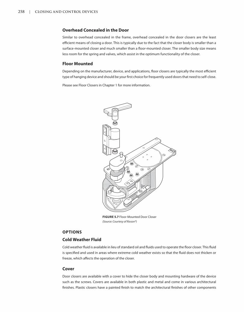
258 | CLOSING AND CONTROL DEVICES
c05.indd Page 258 03/03/2015 03:59:0:PM
FIGURE 5.7 Floor-Mounted Door Closer
(Source: Courtesy of Rixson®)
Overhead Concealed in the Door
Similar to overhead concealed in the frame, overhead concealed in the door closers are the least
efficient means of closing a door. This is typically due to the fact that the closer body is smaller than a
surface-mounted closer and much smaller than a floor-mounted closer. The smaller body size means
less room for the spring and valves, which assist in the optimum functionality of the closer.
Floor Mounted
Depending on the manufacturer, device, and applications, floor closers are typically the most efficient
type of hanging device and should be your first choice for frequently used doors that need to self-close.
Please see Floor Closers in Chapter 1 for more information.
OPTIONS
Cold Weather Fluid
Cold weather fluid is available in lieu of standard oil and fluids used to operate the floor closer. This fluid
is specified and used in areas where extreme cold weather exists so that the fluid does not thicken or
freeze, which affects the operation of the closer.
Cover
Door closers are available with a cover to hide the closer body and mounting hardware of the device
such as the screws. Covers are available in both plastic and metal and come in various architectural
finishes. Plastic closers have a painted finish to match the architectural finishes of other components
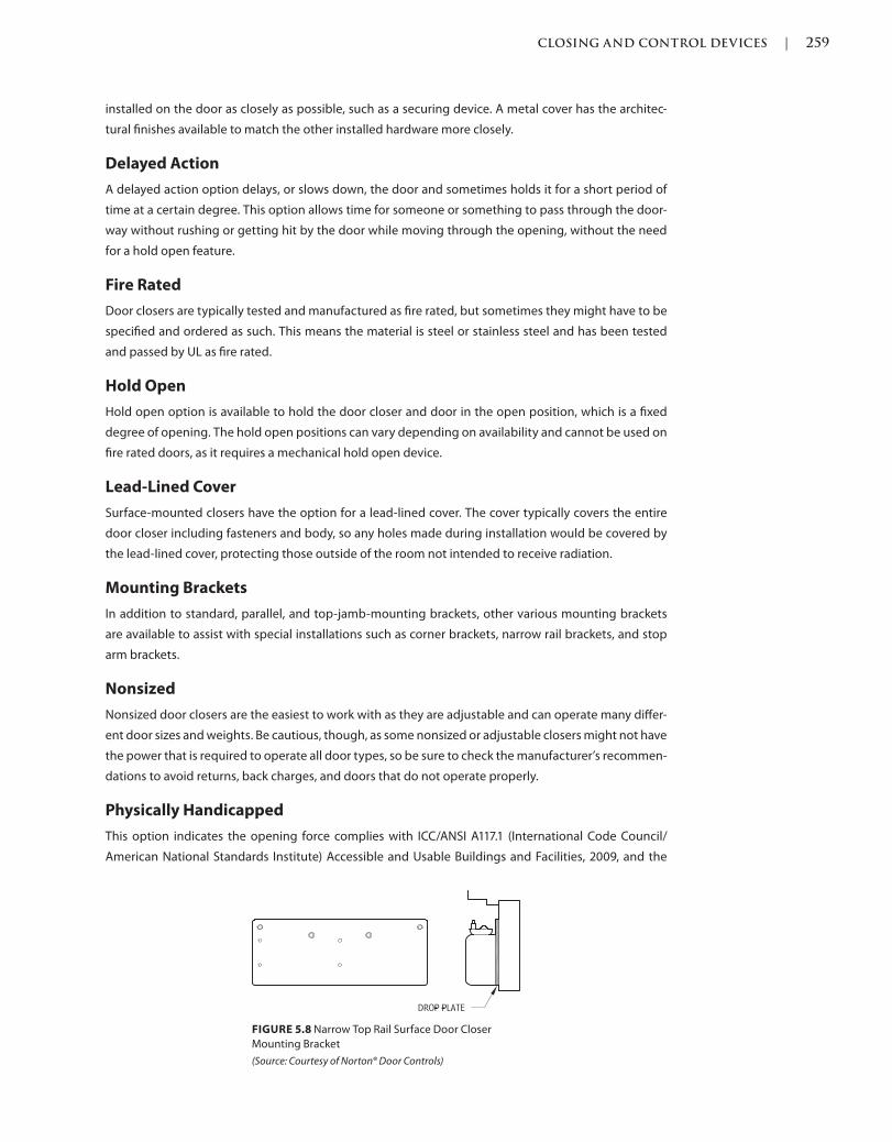
CLOSING AND CONTROL DEVICES | 259
c05.indd Page 259 03/03/2015 03:59:0:PM
installed on the door as closely as possible, such as a securing device. A metal cover has the architec-
tural finishes available to match the other installed hardware more closely.
Delayed Action
A delayed action option delays, or slows down, the door and sometimes holds it for a short period of
time at a certain degree. This option allows time for someone or something to pass through the door-
way without rushing or getting hit by the door while moving through the opening, without the need
for a hold open feature.
Fire Rated
Door closers are typically tested and manufactured as fire rated, but sometimes they might have to be
specified and ordered as such. This means the material is steel or stainless steel and has been tested
and passed by UL as fire rated.
Hold Open
Hold open option is available to hold the door closer and door in the open position, which is a fixed
degree of opening. The hold open positions can vary depending on availability and cannot be used on
fire rated doors, as it requires a mechanical hold open device.
Lead-Lined Cover
Surface-mounted closers have the option for a lead-lined cover. The cover typically covers the entire
door closer including fasteners and body, so any holes made during installation would be covered by
the lead-lined cover, protecting those outside of the room not intended to receive radiation.
Mounting Brackets
In addition to standard, parallel, and top-jamb-mounting brackets, other various mounting brackets
are available to assist with special installations such as corner brackets, narrow rail brackets, and stop
arm brackets.
Nonsized
Nonsized door closers are the easiest to work with as they are adjustable and can operate many differ-
ent door sizes and weights. Be cautious, though, as some nonsized or adjustable closers might not have
the power that is required to operate all door types, so be sure to check the manufacturer’s recommen-
dations to avoid returns, back charges, and doors that do not operate properly.
Physically Handicapped
This option indicates the opening force complies with ICC/ANSI A117.1 (International Code Council/
American National Standards Institute) Accessible and Usable Buildings and Facilities, 2009, and the
FIGURE 5.8 Narrow Top Rail Surface Door Closer
Mounting Bracket
(Source: Courtesy of Norton® Door Controls)
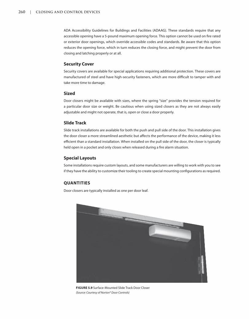
260 | CLOSING AND CONTROL DEVICES
c05.indd Page 260 03/03/2015 03:59:0:PM
ADA Accessibility Guidelines for Buildings and Facilities (ADAAG). These standards require that any
accessible opening have a 5-pound maximum opening force. This option cannot be used on fire rated
or exterior door openings, which override accessible codes and standards. Be aware that this option
reduces the opening force, which in turn reduces the closing force, and might prevent the door from
closing and latching properly or at all.
Security Cover
Security covers are available for special applications requiring additional protection. These covers are
manufactured of steel and have high-security fasteners, which are more difficult to tamper with and
take more time to damage.
Sized
Door closers might be available with sizes, where the spring “size” provides the tension required for
a particular door size or weight. Be cautious when using sized closers as they are not always easily
adjustable and might not operate, that is, open or close a door properly.
Slide Track
Slide track installations are available for both the push and pull side of the door. This installation gives
the door closer a more streamlined aesthetic but affects the performance of the device, making it less
efficient than a standard installation. When installed on the pull side of the door, the closer is typically
held open in a pocket and only closes when released during a fire alarm situation.
Special Layouts
Some installations require custom layouts, and some manufacturers are willing to work with you to see
if they have the ability to customize their tooling to create special mounting configurations as required.
QUANTITIES
Door closers are typically installed as one per door leaf.
FIGURE 5.9 Surface-Mounted Slide Track Door Closer
(Source: Courtesy of Norton® Door Controls)
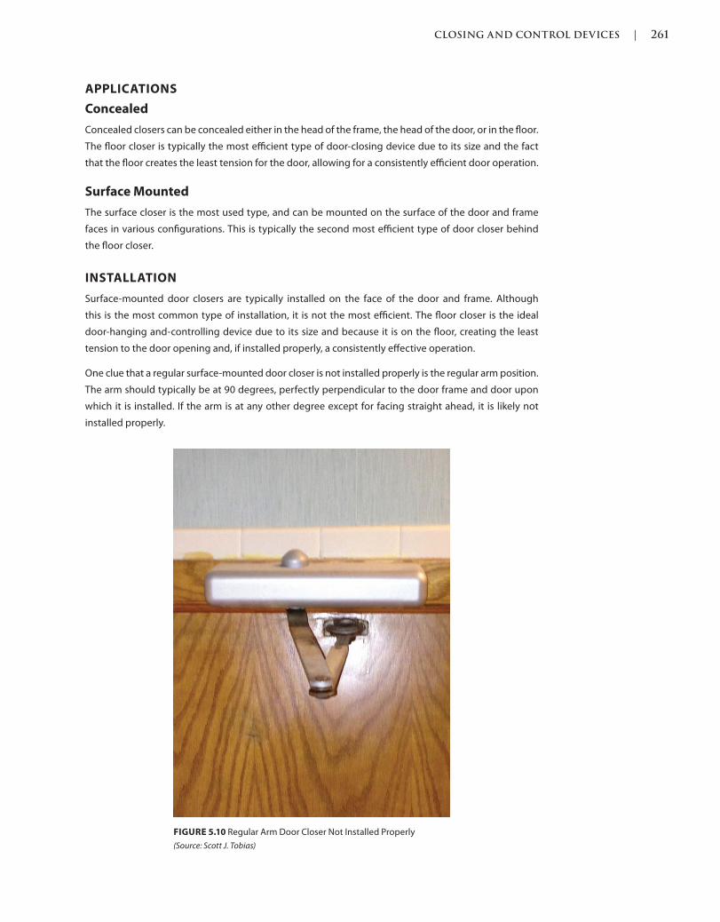
CLOSING AND CONTROL DEVICES | 261
c05.indd Page 261 03/03/2015 03:59:0:PM
APPLICATIONS
Concealed
Concealed closers can be concealed either in the head of the frame, the head of the door, or in the floor.
The floor closer is typically the most efficient type of door-closing device due to its size and the fact
that the floor creates the least tension for the door, allowing for a consistently efficient door operation.
Surface Mounted
The surface closer is the most used type, and can be mounted on the surface of the door and frame
faces in various configurations. This is typically the second most efficient type of door closer behind
the floor closer.
INSTALLATION
Surface-mounted door closers are typically installed on the face of the door and frame. Although
this is the most common type of installation, it is not the most efficient. The floor closer is the ideal
door-hanging and-controlling device due to its size and because it is on the floor, creating the least
tension to the door opening and, if installed properly, a consistently effective operation.
One clue that a regular surface-mounted door closer is not installed properly is the regular arm position.
The arm should typically be at 90 degrees, perfectly perpendicular to the door frame and door upon
which it is installed. If the arm is at any other degree except for facing straight ahead, it is likely not
installed properly.
FIGURE 5.10 Regular Arm Door Closer Not Installed Properly
(Source: Scott J. Tobias)
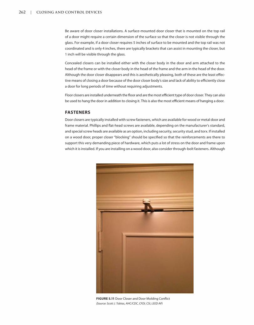
262 | CLOSING AND CONTROL DEVICES
c05.indd Page 262 03/03/2015 03:59:0:PM
Be aware of door closer installations. A surface-mounted door closer that is mounted on the top rail
of a door might require a certain dimension of the surface so that the closer is not visible through the
glass. For example, if a door closer requires 5 inches of surface to be mounted and the top rail was not
coordinated and is only 4 inches, there are typically brackets that can assist in mounting the closer, but
1 inch will be visible through the glass.
Concealed closers can be installed either with the closer body in the door and arm attached to the
head of the frame or with the closer body in the head of the frame and the arm in the head of the door.
Although the door closer disappears and this is aesthetically pleasing, both of these are the least effec-
tive means of closing a door because of the door closer body’s size and lack of ability to efficiently close
a door for long periods of time without requiring adjustments.
Floor closers are installed underneath the floor and are the most efficient type of door closer. They can also
be used to hang the door in addition to closing it. This is also the most efficient means of hanging a door.
FASTENERS
Door closers are typically installed with screw fasteners, which are available for wood or metal door and
frame material. Phillips and flat-head screws are available, depending on the manufacturer’s standard,
and special screw heads are available as an option, including security, security stud, and torx. If installed
on a wood door, proper closer “blocking” should be specified so that the reinforcements are there to
support this very demanding piece of hardware, which puts a lot of stress on the door and frame upon
which it is installed. If you are installing on a wood door, also consider through-bolt fasteners. Although
FIGURE 5.11 Door Closer and Door Molding Conflict
(Source: Scott J. Tobias, AHC/CDC, CFDI, CSI, LEED AP)
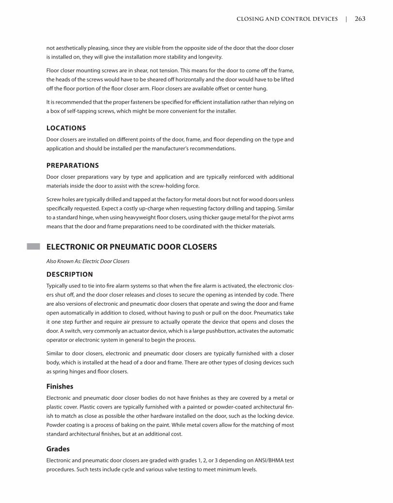
CLOSING AND CONTROL DEVICES | 263
c05.indd Page 263 03/03/2015 03:59:0:PM
not aesthetically pleasing, since they are visible from the opposite side of the door that the door closer
is installed on, they will give the installation more stability and longevity.
Floor closer mounting screws are in shear, not tension. This means for the door to come off the frame,
the heads of the screws would have to be sheared off horizontally and the door would have to be lifted
off the floor portion of the floor closer arm. Floor closers are available offset or center hung.
It is recommended that the proper fasteners be specified for efficient installation rather than relying on
a box of self-tapping screws, which might be more convenient for the installer.
LOCATIONS
Door closers are installed on different points of the door, frame, and floor depending on the type and
application and should be installed per the manufacturer’s recommendations.
PREPARATIONS
Door closer preparations vary by type and application and are typically reinforced with additional
materials inside the door to assist with the screw-holding force.
Screw holes are typically drilled and tapped at the factory for metal doors but not for wood doors unless
specifically requested. Expect a costly up-charge when requesting factory drilling and tapping. Similar
to a standard hinge, when using heavyweight floor closers, using thicker gauge metal for the pivot arms
means that the door and frame preparations need to be coordinated with the thicker materials.
ELECTRONIC OR PNEUMATIC DOOR CLOSERS
Also Known As: Electric Door Closers
DESCRIPTION
Typically used to tie into fire alarm systems so that when the fire alarm is activated, the electronic clos-
ers shut off, and the door closer releases and closes to secure the opening as intended by code. There
are also versions of electronic and pneumatic door closers that operate and swing the door and frame
open automatically in addition to closed, without having to push or pull on the door. Pneumatics take
it one step further and require air pressure to actually operate the device that opens and closes the
door. A switch, very commonly an actuator device, which is a large pushbutton, activates the automatic
operator or electronic system in general to begin the process.
Similar to door closers, electronic and pneumatic door closers are typically furnished with a closer
body, which is installed at the head of a door and frame. There are other types of closing devices such
as spring hinges and floor closers.
Finishes
Electronic and pneumatic door closer bodies do not have finishes as they are covered by a metal or
plastic cover. Plastic covers are typically furnished with a painted or powder-coated architectural fin-
ish to match as close as possible the other hardware installed on the door, such as the locking device.
Powder coating is a process of baking on the paint. While metal covers allow for the matching of most
standard architectural finishes, but at an additional cost.
Grades
Electronic and pneumatic door closers are graded with grades 1, 2, or 3 depending on ANSI/BHMA test
procedures. Such tests include cycle and various valve testing to meet minimum levels.
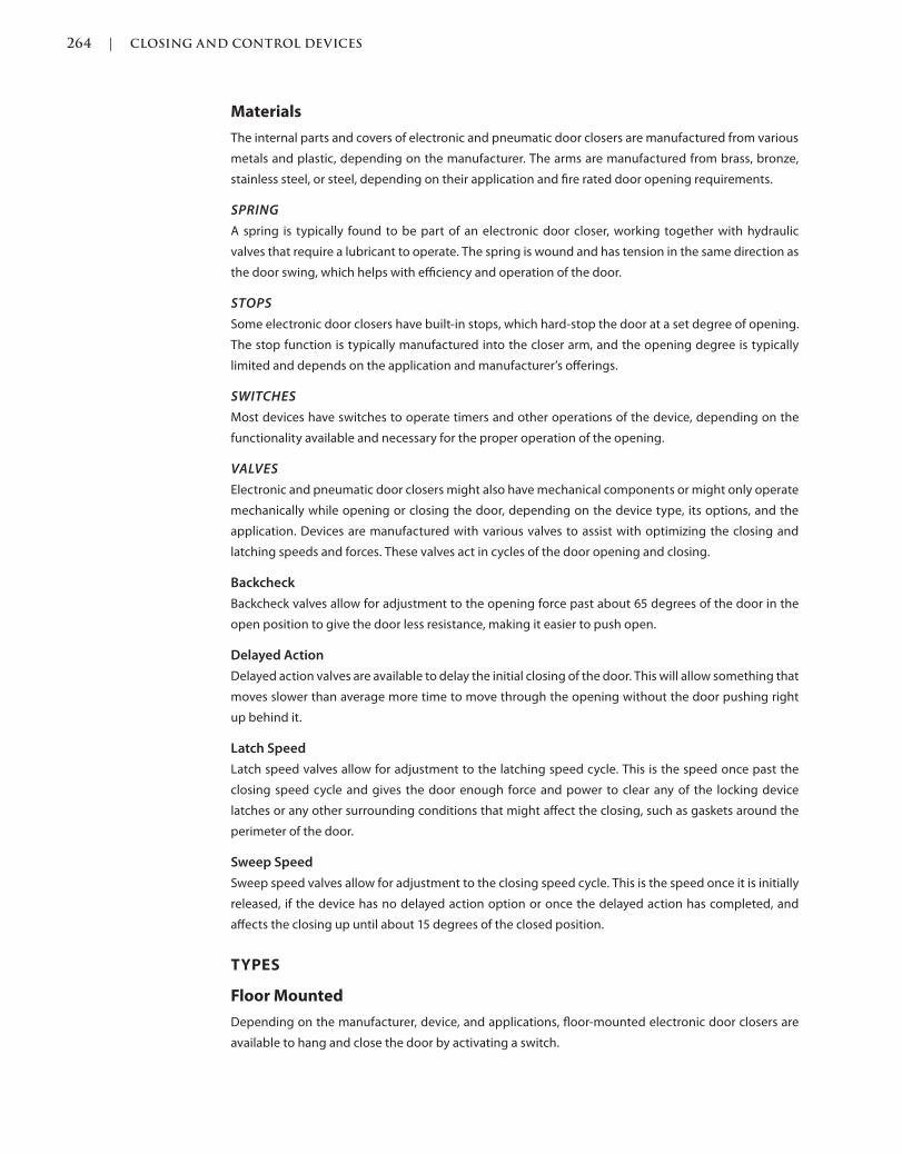
264 | CLOSING AND CONTROL DEVICES
c05.indd Page 264 03/03/2015 03:59:0:PM
Materials
The internal parts and covers of electronic and pneumatic door closers are manufactured from various
metals and plastic, depending on the manufacturer. The arms are manufactured from brass, bronze,
stainless steel, or steel, depending on their application and fire rated door opening requirements.
SPRING
A spring is typically found to be part of an electronic door closer, working together with hydraulic
valves that require a lubricant to operate. The spring is wound and has tension in the same direction as
the door swing, which helps with efficiency and operation of the door.
STOPS
Some electronic door closers have built-in stops, which hard-stop the door at a set degree of opening.
The stop function is typically manufactured into the closer arm, and the opening degree is typically
limited and depends on the application and manufacturer’s offerings.
SWITCHES
Most devices have switches to operate timers and other operations of the device, depending on the
functionality available and necessary for the proper operation of the opening.
VALVES
Electronic and pneumatic door closers might also have mechanical components or might only operate
mechanically while opening or closing the door, depending on the device type, its options, and the
application. Devices are manufactured with various valves to assist with optimizing the closing and
latching speeds and forces. These valves act in cycles of the door opening and closing.
Backcheck
Backcheck valves allow for adjustment to the opening force past about 65 degrees of the door in the
open position to give the door less resistance, making it easier to push open.
Delayed Action
Delayed action valves are available to delay the initial closing of the door. This will allow something that
moves slower than average more time to move through the opening without the door pushing right
up behind it.
Latch Speed
Latch speed valves allow for adjustment to the latching speed cycle. This is the speed once past the
closing speed cycle and gives the door enough force and power to clear any of the locking device
latches or any other surrounding conditions that might affect the closing, such as gaskets around the
perimeter of the door.
Sweep Speed
Sweep speed valves allow for adjustment to the closing speed cycle. This is the speed once it is initially
released, if the device has no delayed action option or once the delayed action has completed, and
affects the closing up until about 15 degrees of the closed position.
TYPES
Floor Mounted
Depending on the manufacturer, device, and applications, floor-mounted electronic door closers are
available to hang and close the door by activating a switch.

CLOSING AND CONTROL DEVICES | 265
c05.indd Page 265 03/03/2015 03:59:0:PM
Overhead Concealed in the Frame
Overhead concealed in the frame door closers have been known to be the least efficient means of clos-
ing a door. This is typically due to the fact that the closer body is smaller than that of a surface-mounted
closer and much smaller than that of a floor-mounted closer. The smaller body size means less room for
a spring and valves, which assist in the optimum functionality of the closer.
Surface Mounted
MOTION SENSOR HOLD OPEN
Some manufacturers offer an electronic motion sensor built into their door closer. This sensor detects
movement in the doorway, which holds the door in the open position until there is no movement. Once
there is no movement detected, the door closer releases, but if someone stands still in the opening, the
door will not sense the presence and will release and close automatically. Of course, this could result in
injury, so it is important to keep moving through the doorway.
FIGURE 5.12 Electronic Motion Sensor Hold Open Door Closer
(Source: Courtesy of Norton® Door Controls)
PARALLEL ARM
The parallel arm surface-mounted electronic door closer mounts on the push side of the door and the
arm is parallel with the door, making it less susceptible to vandalism or hanging off the arm. This type of
installation is less efficient than the regular arm installation due to the configuration and requires more
tension in the spring to close effectively.
REGULAR ARM
The regular arm surface-mounted electronic door closer is always mounted on the pull side of the door,
with the arm protruding off the face of the door and frame. Regular arm installation is the most efficient
of the surface-mounted installations due to the configuration and force of the arm.
SMOKE DETECTOR
Electronic closers can have a smoke detector feature that can be tied into a facility fire alarm system.
Normally the door is held open, like a corridor door in a high-rise office building, but when the smoke
is detected the alarm is set off, the closers release, and they close to secure the nonfire side of the
door from the fire side.
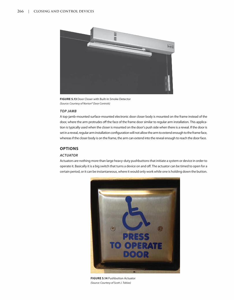
266 | CLOSING AND CONTROL DEVICES
c05.indd Page 266 03/03/2015 03:59:0:PM
TOP JAMB
A top-jamb-mounted surface-mounted electronic door closer body is mounted on the frame instead of the
door, where the arm protrudes off the face of the frame door similar to regular arm installation. This applica-
tion is typically used when the closer is mounted on the door’s push side when there is a reveal. If the door is
set in a reveal, regular arm installation configuration will not allow the arm to extend enough to the frame face,
whereas if the closer body is on the frame, the arm can extend into the reveal enough to reach the door face.
OPTIONS
ACTUATOR
Actuators are nothing more than large heavy-duty pushbuttons that initiate a system or device in order to
operate it. Basically it is a big switch that turns a device on and off. The actuator can be timed to open for a
certain period, or it can be instantaneous, where it would only work while one is holding down the button.
FIGURE 5.13 Door Closer with Built-In Smoke Detector
(Source: Courtesy of Norton® Door Controls)
FIGURE 5.14 Pushbutton Actuator
(Source: Courtesy of Scott J. Tobias)
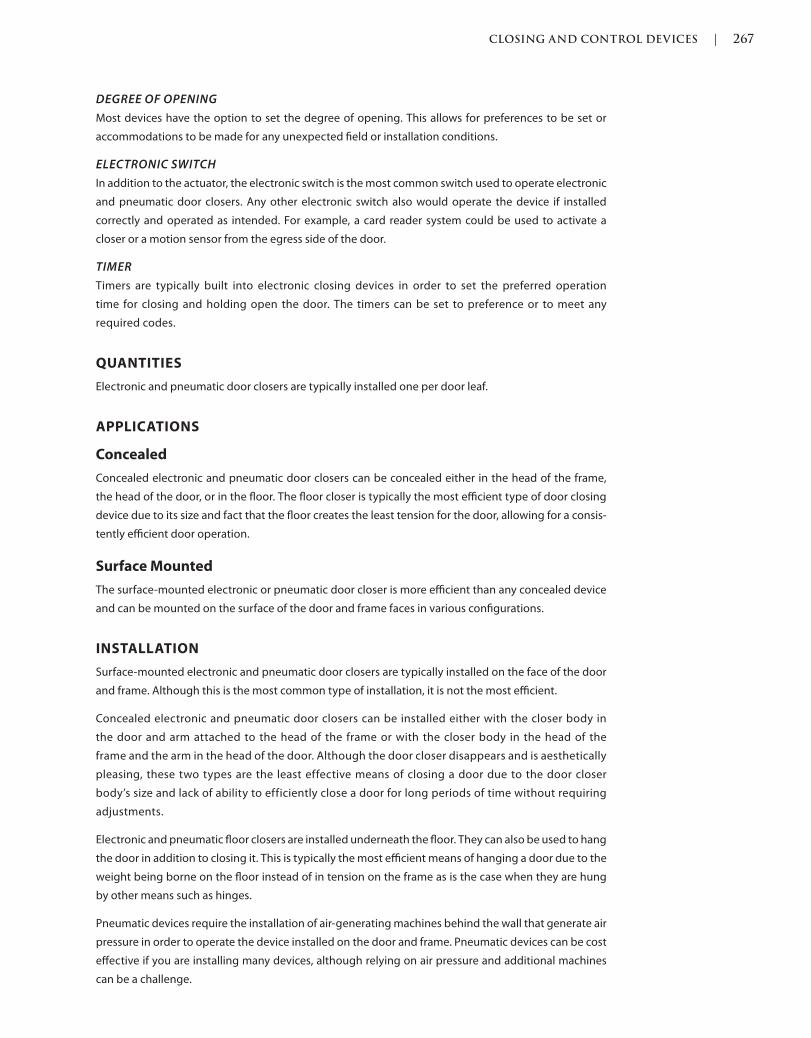
CLOSING AND CONTROL DEVICES | 267
c05.indd Page 267 03/03/2015 03:59:0:PM
DEGREE OF OPENING
Most devices have the option to set the degree of opening. This allows for preferences to be set or
accommodations to be made for any unexpected field or installation conditions.
ELECTRONIC SWITCH
In addition to the actuator, the electronic switch is the most common switch used to operate electronic
and pneumatic door closers. Any other electronic switch also would operate the device if installed
correctly and operated as intended. For example, a card reader system could be used to activate a
closer or a motion sensor from the egress side of the door.
TIMER
Timers are typically built into electronic closing devices in order to set the preferred operation
time for closing and holding open the door. The timers can be set to preference or to meet any
required codes.
QUANTITIES
Electronic and pneumatic door closers are typically installed one per door leaf.
APPLICATIONS
Concealed
Concealed electronic and pneumatic door closers can be concealed either in the head of the frame,
the head of the door, or in the floor. The floor closer is typically the most efficient type of door closing
device due to its size and fact that the floor creates the least tension for the door, allowing for a consis-
tently efficient door operation.
Surface Mounted
The surface-mounted electronic or pneumatic door closer is more efficient than any concealed device
and can be mounted on the surface of the door and frame faces in various configurations.
INSTALLATION
Surface-mounted electronic and pneumatic door closers are typically installed on the face of the door
and frame. Although this is the most common type of installation, it is not the most efficient.
Concealed electronic and pneumatic door closers can be installed either with the closer body in
the door and arm attached to the head of the frame or with the closer body in the head of the
frame and the arm in the head of the door. Although the door closer disappears and is aesthetically
pleasing, these two types are the least effective means of closing a door due to the door closer
body’s size and lack of ability to efficiently close a door for long periods of time without requiring
adjustments.
Electronic and pneumatic floor closers are installed underneath the floor. They can also be used to hang
the door in addition to closing it. This is typically the most efficient means of hanging a door due to the
weight being borne on the floor instead of in tension on the frame as is the case when they are hung
by other means such as hinges.
Pneumatic devices require the installation of air-generating machines behind the wall that generate air
pressure in order to operate the device installed on the door and frame. Pneumatic devices can be cost
effective if you are installing many devices, although relying on air pressure and additional machines
can be a challenge.
268 | CLOSING AND CONTROL DEVICES
c05.indd Page 268 03/03/2015 03:59:0:PM
Be aware of device installations. A surface-mounted device that is mounted on the top rail of a door
might require a certain dimension of the surface so that the device is not visible through the glass. For
example, if a device requires 5 inches of surface to be mounted on and the top rail is not coordinated
and is only 4 inches, there are typically brackets that can assist in mounting the device, but 1 inch will
be visible through the glass.
FASTENERS
Electronic door closers are typically installed with screw fasteners, which are available for wood or
metal door and frame material. Phillips and flat-head screws are available, depending on the manufac-
turer’s standard, and special screw heads are available as an option, including security, security stud,
and torx. If the door closer is installed on a wood door, proper closer “blocking” should be specified
so that the reinforcements are there to support this very demanding piece of hardware, which puts a
lot of stress on the door and frame upon which it is installed. If you are installing on a wood door, also
consider through-bolt fasteners. Although not aesthetically pleasing, since they are visible from the
opposite side of the door that the door closer is installed on, they will give the installation more stabil-
ity and longevity.
Floor closer mounting screws are in shear, not tension. This means for the door to come off the
frame, the heads of the screws would have to be sheared off horizontally and the door would
have to be lifted off the floor portion of the floor closer arm. Floor closers are available as offset
or center hung.
It is recommended that the proper fasteners be specified for efficient installation rather than relying on
a box of self-tapping screws, which might be more convenient for the installer.
LOCATIONS
Electronic door closers are installed on different points of the door, frame, and floor, depending on the
type and application and should be installed per the manufacturer’s recommendations.
PREPARATIONS
Electronic door closer preparations vary by type and application and are typically reinforced with addi-
tional materials inside the door to assist with the screw-holding force.
Screw holes are typically drilled and tapped at the factory for metal doors but not for wood doors,
unless specifically requested. Expect a costly up-charge when requesting factory drilling and tapping.
Similar to a standard hinge, when using heavyweight floor closers, using thicker-gauge metal for the
pivot arms means that the materials will be thicker and the door and frame preparations need to be
coordinated.
POWEROPERATED DOOR CLOSERS
Also Known As: Automatic Operators, Auto Operators, Automatic Door Openers, Auto Door Openers,
Electric Door Closers
DESCRIPTION
Typically used to assist with the operation of a doorway, such as an accessible opening for the elderly
or disabled, a switch, very commonly an actuator device, which is a large pushbutton, activates the
automatic operator or electronic system in general to begin the process.
CLOSING AND CONTROL DEVICES | 269
c05.indd Page 269 03/03/2015 03:59:0:PM
Similar to standard door closers, power-operated door closers are typically furnished with a closer
body, which is installed at the head of a door and frame.
Finishes
Power-operated door closer bodies do not have finishes as they are covered by a metal or plastic cover.
Plastic covers are typically furnished with a painted or powder-coated architectural finish to match as
closely as possible the other hardware installed on the door such as the locking device. Powder coating
is a process of baking on the paint. Metal covers allow for the matching of most standard architectural
finishes, but for an additional cost.
Grades
Power-operated door closers are graded with grades 1, 2, or 3 depending on ANSI/BHMA test proce-
dures. Such tests include cycle- and various valve- testing to meet minimum levels.
Materials
The internal parts and covers of power-operated door closers are manufactured from various metals
and plastic, depending on the manufacturer. The arms are manufactured from brass, bronze, stainless
steel, or steel, depending on their application and fire rated door opening requirements.
SPRING
A spring is typically found to be part of a power-operated door closer, working together with hydraulic
valves that require a lubricant to operate. The spring is wound and has tension in the same direction as
the door swing, which helps with efficiency and operation of the door.
STOPS
Some power-operated door closers have built-in stops, which hard-stop the door at a set degree of
opening. The stop function is typically manufactured into the closer arm and the opening degree is
typically limited and depends on the application and manufacturer’s available choices.
SWITCHES
Most devices have switches to operate timers and other operations of the device, depending on the
functionality available and necessary for the proper operation of the opening.
VALVES
Power-operated door closers might also have mechanical components or might only operate mechani-
cally while opening or closing the door, depending on the device type, its options, and its application.
Devices are manufactured with various valves to assist with optimizing the closing and latching speeds
and forces. These valves act in cycles of the door opening and closing.
Backcheck
Backcheck valves allow for adjustment to the opening force past about 65 degrees of the door in the
open position to give the door less resistance and to make it easier to push open.
Delayed Action
Delayed action valves are available to delay the initial closing of the door. This will allow something that
moves slower than average more time to move through the opening without the door pushing right
up behind it.
Latch Speed
Latch speed valves allow for adjustment to the latching speed cycle. This is the speed once past the
closing speed cycle that gives the door enough force and power to clear any of the locking device
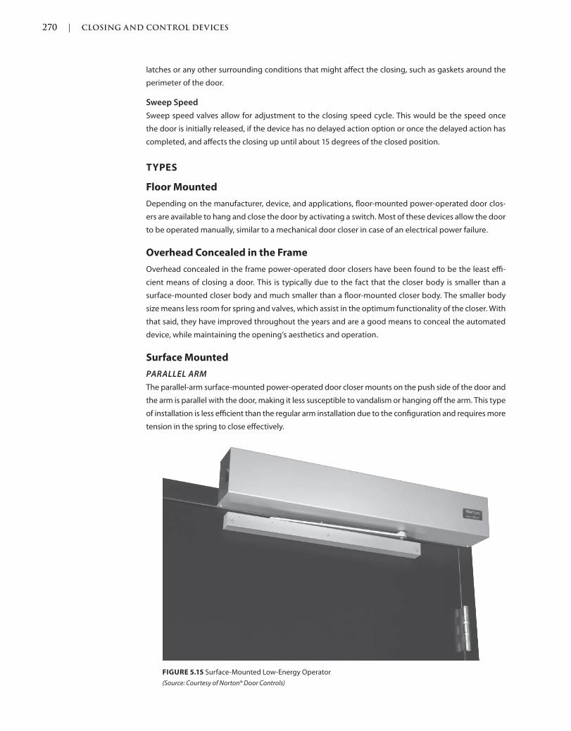
270 | CLOSING AND CONTROL DEVICES
c05.indd Page 270 03/03/2015 03:59:0:PM
latches or any other surrounding conditions that might affect the closing, such as gaskets around the
perimeter of the door.
Sweep Speed
Sweep speed valves allow for adjustment to the closing speed cycle. This would be the speed once
the door is initially released, if the device has no delayed action option or once the delayed action has
completed, and affects the closing up until about 15 degrees of the closed position.
TYPES
Floor Mounted
Depending on the manufacturer, device, and applications, floor-mounted power-operated door clos-
ers are available to hang and close the door by activating a switch. Most of these devices allow the door
to be operated manually, similar to a mechanical door closer in case of an electrical power failure.
Overhead Concealed in the Frame
Overhead concealed in the frame power-operated door closers have been found to be the least effi-
cient means of closing a door. This is typically due to the fact that the closer body is smaller than a
surface-mounted closer body and much smaller than a floor-mounted closer body. The smaller body
size means less room for spring and valves, which assist in the optimum functionality of the closer. With
that said, they have improved throughout the years and are a good means to conceal the automated
device, while maintaining the opening’s aesthetics and operation.
Surface Mounted
PARALLEL ARM
The parallel-arm surface-mounted power-operated door closer mounts on the push side of the door and
the arm is parallel with the door, making it less susceptible to vandalism or hanging off the arm. This type
of installation is less efficient than the regular arm installation due to the configuration and requires more
tension in the spring to close effectively.
FIGURE 5.15 Surface-Mounted Low-Energy Operator
(Source: Courtesy of Norton® Door Controls)

CLOSING AND CONTROL DEVICES | 271
c05.indd Page 271 03/03/2015 03:59:0:PM
REGULAR ARM
The regular arm surface-mounted power-operated door closer is always mounted on the pull side
of the door, with the arm protruding off the face of the door and frame. Regular arm installation
is the most efficient of the surface-mounted installations due to the configuration and force of
the arm.
TOP JAMB
A top-jamb-mounted surface-mounted electronic door closer body is mounted on the frame instead of
the door, where the arm protrudes off the face of the frame door similar to regular arm installation. This
application is typically used when the closer is mounted on the door’s push side when there is a reveal.
If the door is set in a reveal, regular arm installation configuration will not allow the arm to extend
enough to the frame face, whereas if the closer body is on the frame, the arm can extend into the reveal
enough to reach the door face.
OPTIONS
ACTUATOR
Actuators are nothing more than large, heavy-duty pushbuttons that initiate a system or device in
order to operate it. Basically, an actuator is a big switch that turns a device on and off. The actuator can
be timed to open for a certain period of time, or it can be instantaneous, where it only works while one
is holding down the button.
DEGREE OF OPENING
Most devices have an option to set the degree of opening. This allows for preferences to be set or
accommodations to be made for any field or installation conditions that were unexpected.
ELECTRONIC SWITCH
In addition to the actuator, the electronic switch is the most common switch used to operate electronic
and pneumatic door closers. Any other electronic switch would also operate the device if installed
correctly and operated as intended. For example, a card reader system can be used to activate a closer
or a motion sensor from the egress side of the door.
FLOOR MATS
Floor mats are available to act as a switch, similar to those you might be familiar with at a grocery store.
When you step on the mat a switch is activated, which starts the operation of automatically operating
and swinging open the door.
HIGH ENERGY
Some devices are available in high energy versions. They operate at faster speeds and might
require a higher voltage or more amps for operation. These devices are typically used on exterior
openings and any door that might need to open and close quickly, like an operating room door in
a hospital.
LOW ENERGY
Most common devices are low or standard energy. They operate at standard speeds and likely require
standard voltage and amps for operation. These devices are typically used on interior openings such as
corridors, restrooms, or any door that might need assistance automatically.
MOTION SENSORS
Motion sensors are available as a switch, typically on the egress side of a power-operated door. When
one moves toward the opening in order to egress, the sensor senses the movement, which starts the
operation of automatically operating and swinging open the door.
272 | CLOSING AND CONTROL DEVICES
c05.indd Page 272 03/03/2015 03:59:0:PM
SAFETY RAILS
When high-energy devices are installed, some codes and standards require the use of safety rails on
either side leading up to the opening. These rails act as a guide into the opening and assist with mini-
mizing any injuries from the high-powered operation of the door.
SENSORS
When high-energy devices are installed, some codes and standards require the use of sensors on
either side of the opening to sense any presence that might interfere or injure a person in the path
of operation. These sensors assist with minimizing any injuries from the high-powered operation of
the door.
SERVICE CONTRACTS
High-energy power-operated door operators are installed by the provider or certified manufacturer
installer in order to ensure optimum installation and maintenance. These installations typically offer
service contracts, which require a monthly fee and long-term commitment. This gives the owner secu-
rity knowing that someone is always on call if something is not operating properly on a highly sensitive
and active door opening.
TIMER
Timers are typically built into power-operated door closing devices in order to set the preferred opera-
tion time for closing and holding open the door. The timers can be set to preference or to meet any
required codes.
QUANTITIES
Powered door closers are typically installed one per door leaf, although there are devices built for a
pair of doors.
APPLICATIONS
Concealed
Concealed power-operated door closers can be concealed either in the head of the frame, the head of
the door, or in the floor. The floor closer is typically the most efficient type of door closing device due to
its size and fact that the floor creates the least tension for the door, allowing for a consistently efficient
door operation.
Surface Mounted
The surface-mounted power-operated door closer is more efficient than any concealed device and can
be mounted on the surface of the door and frame faces in various configurations.
INSTALLATION
Surface-mounted power-operated door closers are typically installed on the face of the door and frame.
Although this is the most common type of installation, it is not the most efficient. The floor closer is the
ideal door hanging and controlling device.
Concealed power-operated door closers can either be installed with the closer body in the door and
arm attached to the head of the frame, or the closer body in the head of the frame and the arm in the
head of the door. Although the door closer disappears, and this is aesthetically pleasing, these two
types are the least effective means of closing a door due to the door closer body’s size and lack of
ability to efficiently close a door for long periods of time without requiring adjustments.
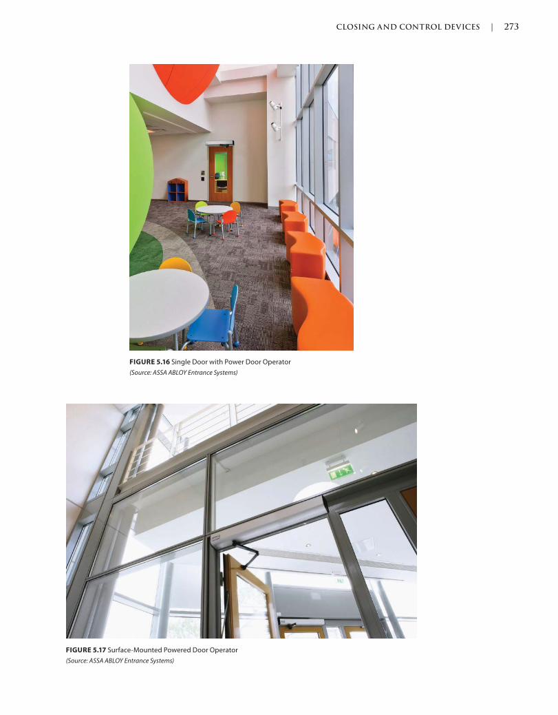
CLOSING AND CONTROL DEVICES | 273
c05.indd Page 273 03/03/2015 03:59:0:PM
FIGURE 5.16 Single Door with Power Door Operator
(Source: ASSA ABLOY Entrance Systems)
FIGURE 5.17 Surface-Mounted Powered Door Operator
(Source: ASSA ABLOY Entrance Systems)
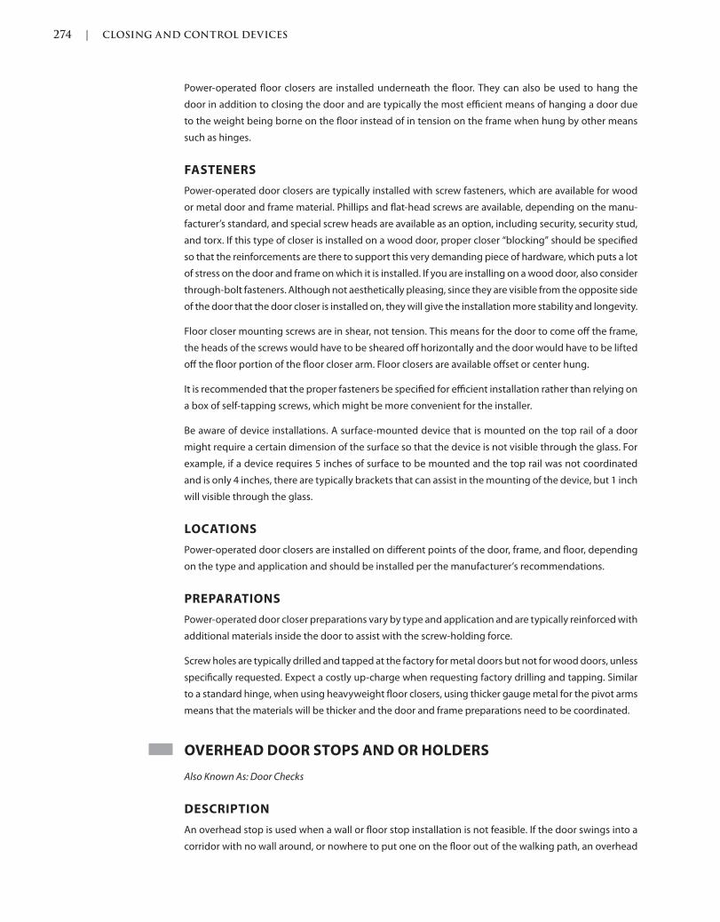
274 | CLOSING AND CONTROL DEVICES
c05.indd Page 274 03/03/2015 03:59:0:PM
Power-operated floor closers are installed underneath the floor. They can also be used to hang the
door in addition to closing the door and are typically the most efficient means of hanging a door due
to the weight being borne on the floor instead of in tension on the frame when hung by other means
such as hinges.
FASTENERS
Power-operated door closers are typically installed with screw fasteners, which are available for wood
or metal door and frame material. Phillips and flat-head screws are available, depending on the manu-
facturer’s standard, and special screw heads are available as an option, including security, security stud,
and torx. If this type of closer is installed on a wood door, proper closer “blocking” should be specified
so that the reinforcements are there to support this very demanding piece of hardware, which puts a lot
of stress on the door and frame on which it is installed. If you are installing on a wood door, also consider
through-bolt fasteners. Although not aesthetically pleasing, since they are visible from the opposite side
of the door that the door closer is installed on, they will give the installation more stability and longevity.
Floor closer mounting screws are in shear, not tension. This means for the door to come off the frame,
the heads of the screws would have to be sheared off horizontally and the door would have to be lifted
off the floor portion of the floor closer arm. Floor closers are available offset or center hung.
It is recommended that the proper fasteners be specified for efficient installation rather than relying on
a box of self-tapping screws, which might be more convenient for the installer.
Be aware of device installations. A surface-mounted device that is mounted on the top rail of a door
might require a certain dimension of the surface so that the device is not visible through the glass. For
example, if a device requires 5 inches of surface to be mounted and the top rail was not coordinated
and is only 4 inches, there are typically brackets that can assist in the mounting of the device, but 1 inch
will visible through the glass.
LOCATIONS
Power-operated door closers are installed on different points of the door, frame, and floor, depending
on the type and application and should be installed per the manufacturer’s recommendations.
PREPARATIONS
Power-operated door closer preparations vary by type and application and are typically reinforced with
additional materials inside the door to assist with the screw-holding force.
Screw holes are typically drilled and tapped at the factory for metal doors but not for wood doors, unless
specifically requested. Expect a costly up-charge when requesting factory drilling and tapping. Similar
to a standard hinge, when using heavyweight floor closers, using thicker gauge metal for the pivot arms
means that the materials will be thicker and the door and frame preparations need to be coordinated.
OVERHEAD DOOR STOPS AND OR HOLDERS
Also Known As: Door Checks
DESCRIPTION
An overhead stop is used when a wall or floor stop installation is not feasible. If the door swings into a
corridor with no wall around, or nowhere to put one on the floor out of the walking path, an overhead
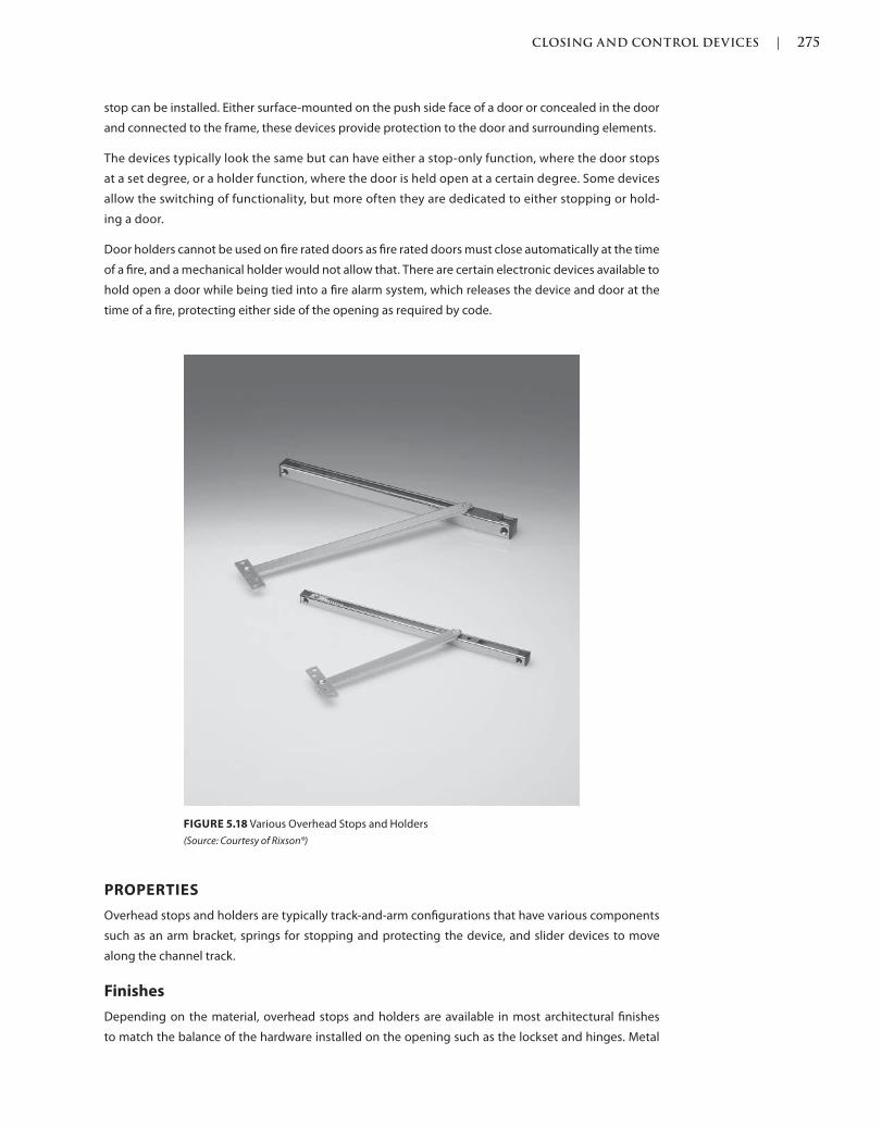
CLOSING AND CONTROL DEVICES | 275
c05.indd Page 275 03/03/2015 03:59:0:PM
stop can be installed. Either surface-mounted on the push side face of a door or concealed in the door
and connected to the frame, these devices provide protection to the door and surrounding elements.
The devices typically look the same but can have either a stop-only function, where the door stops
at a set degree, or a holder function, where the door is held open at a certain degree. Some devices
allow the switching of functionality, but more often they are dedicated to either stopping or hold-
ing a door.
Door holders cannot be used on fire rated doors as fire rated doors must close automatically at the time
of a fire, and a mechanical holder would not allow that. There are certain electronic devices available to
hold open a door while being tied into a fire alarm system, which releases the device and door at the
time of a fire, protecting either side of the opening as required by code.
FIGURE 5.18 Various Overhead Stops and Holders
(Source: Courtesy of Rixson®)
PROPERTIES
Overhead stops and holders are typically track-and-arm configurations that have various components
such as an arm bracket, springs for stopping and protecting the device, and slider devices to move
along the channel track.
Finishes
Depending on the material, overhead stops and holders are available in most architectural finishes
to match the balance of the hardware installed on the opening such as the lockset and hinges. Metal
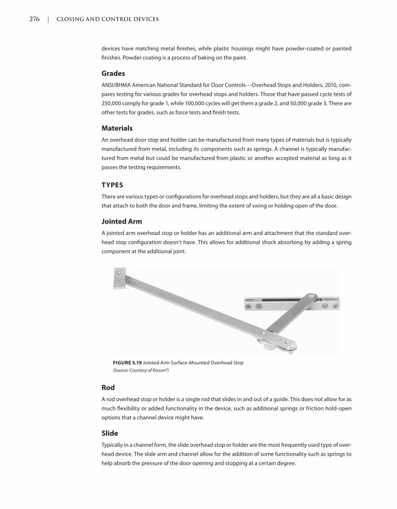
276 | CLOSING AND CONTROL DEVICES
c05.indd Page 276 03/03/2015 03:59:0:PM
devices have matching metal finishes, while plastic housings might have powder-coated or painted
finishes. Powder coating is a process of baking on the paint.
Grades
ANSI/BHMA American National Standard for Door Controls—Overhead Stops and Holders, 2010, com-
pares testing for various grades for overhead stops and holders. Those that have passed cycle tests of
250,000 comply for grade 1, while 100,000 cycles will get them a grade 2, and 50,000 grade 3. There are
other tests for grades, such as force tests and finish tests.
Materials
An overhead door stop and holder can be manufactured from many types of materials but is typically
manufactured from metal, including its components such as springs. A channel is typically manufac-
tured from metal but could be manufactured from plastic or another accepted material as long as it
passes the testing requirements.
TYPES
There are various types or configurations for overhead stops and holders, but they are all a basic design
that attach to both the door and frame, limiting the extent of swing or holding open of the door.
Jointed Arm
A jointed arm overhead stop or holder has an additional arm and attachment that the standard over-
head stop configuration doesn’t have. This allows for additional shock absorbing by adding a spring
component at the additional joint.
FIGURE 5.19 Jointed Arm Surface-Mounted Overhead Stop
(Source: Courtesy of Rixson®)
Rod
A rod overhead stop or holder is a single rod that slides in and out of a guide. This does not allow for as
much flexibility or added functionality in the device, such as additional springs or friction hold-open
options that a channel device might have.
Slide
Typically in a channel form, the slide overhead stop or holder are the most frequently used type of over-
head device. The slide arm and channel allow for the addition of some functionality such as springs to
help absorb the pressure of the door opening and stopping at a certain degree.
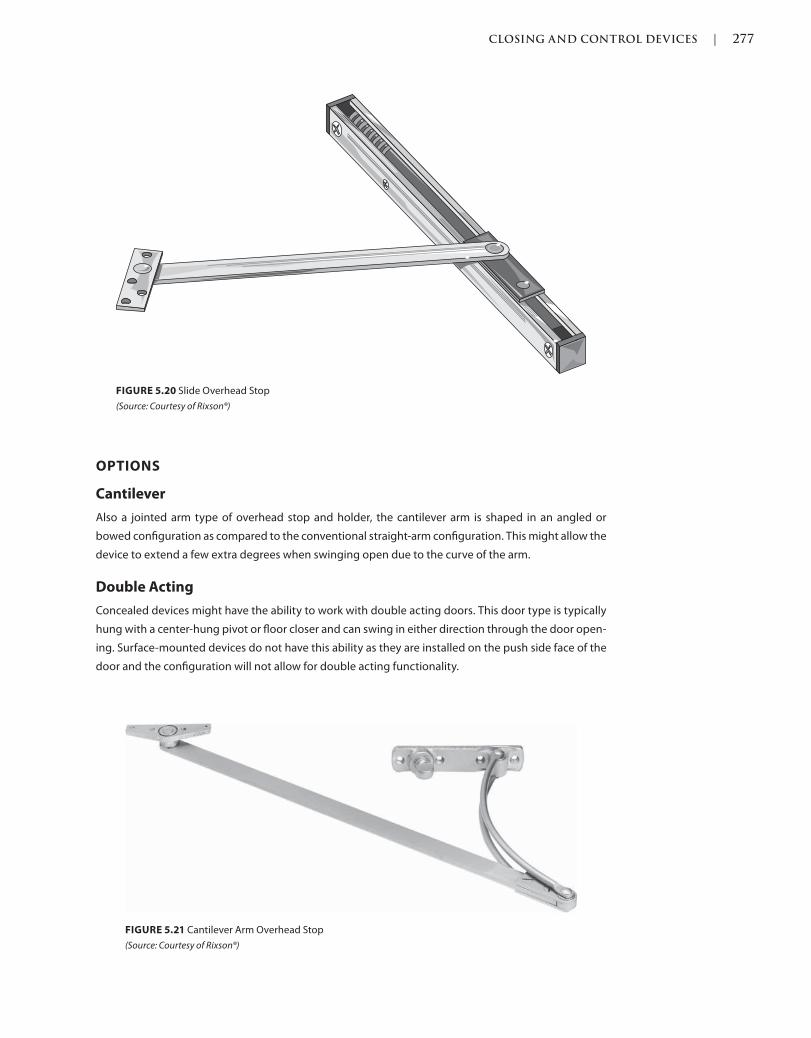
CLOSING AND CONTROL DEVICES | 277
c05.indd Page 277 03/03/2015 03:59:0:PM
OPTIONS
Cantilever
Also a jointed arm type of overhead stop and holder, the cantilever arm is shaped in an angled or
bowed configuration as compared to the conventional straight-arm configuration. This might allow the
device to extend a few extra degrees when swinging open due to the curve of the arm.
Double Acting
Concealed devices might have the ability to work with double acting doors. This door type is typically
hung with a center-hung pivot or floor closer and can swing in either direction through the door open-
ing. Surface-mounted devices do not have this ability as they are installed on the push side face of the
door and the configuration will not allow for double acting functionality.
FIGURE 5.20 Slide Overhead Stop
(Source: Courtesy of Rixson®)
FIGURE 5.21 Cantilever Arm Overhead Stop
(Source: Courtesy of Rixson®)
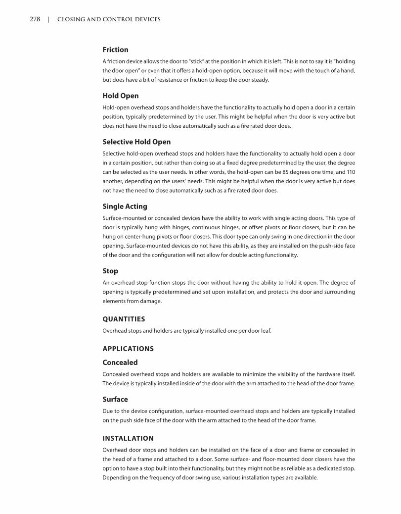
278 | CLOSING AND CONTROL DEVICES
c05.indd Page 278 03/03/2015 03:59:0:PM
Friction
A friction device allows the door to “stick” at the position in which it is left. This is not to say it is “holding
the door open” or even that it offers a hold-open option, because it will move with the touch of a hand,
but does have a bit of resistance or friction to keep the door steady.
Hold Open
Hold-open overhead stops and holders have the functionality to actually hold open a door in a certain
position, typically predetermined by the user. This might be helpful when the door is very active but
does not have the need to close automatically such as a fire rated door does.
Selective Hold Open
Selective hold-open overhead stops and holders have the functionality to actually hold open a door
in a certain position, but rather than doing so at a fixed degree predetermined by the user, the degree
can be selected as the user needs. In other words, the hold-open can be 85 degrees one time, and 110
another, depending on the users’ needs. This might be helpful when the door is very active but does
not have the need to close automatically such as a fire rated door does.
Single Acting
Surface-mounted or concealed devices have the ability to work with single acting doors. This type of
door is typically hung with hinges, continuous hinges, or offset pivots or floor closers, but it can be
hung on center-hung pivots or floor closers. This door type can only swing in one direction in the door
opening. Surface-mounted devices do not have this ability, as they are installed on the push-side face
of the door and the configuration will not allow for double acting functionality.
Stop
An overhead stop function stops the door without having the ability to hold it open. The degree of
opening is typically predetermined and set upon installation, and protects the door and surrounding
elements from damage.
QUANTITIES
Overhead stops and holders are typically installed one per door leaf.
APPLICATIONS
Concealed
Concealed overhead stops and holders are available to minimize the visibility of the hardware itself.
The device is typically installed inside of the door with the arm attached to the head of the door frame.
Surface
Due to the device configuration, surface-mounted overhead stops and holders are typically installed
on the push side face of the door with the arm attached to the head of the door frame.
INSTALLATION
Overhead door stops and holders can be installed on the face of a door and frame or concealed in
the head of a frame and attached to a door. Some surface- and floor-mounted door closers have the
option to have a stop built into their functionality, but they might not be as reliable as a dedicated stop.
Depending on the frequency of door swing use, various installation types are available.
CLOSING AND CONTROL DEVICES | 279
c05.indd Page 279 03/03/2015 03:59:0:PM
Fasteners
Overhead door stops and holders are typically installed with screw fasteners, which are available for
wood or metal door and frame material. Phillips and flat-head screws are available, depending on the
manufacturer’s standard, and special screw heads are available as an option, including security, security
stud, and torx. If the device is installed on a wood door, proper closer “blocking” should be specified so
that the reinforcements are there to support this very demanding piece of hardware, which puts a lot of
stress on the door and frame upon which it is installed. If you are installing on a wood door, also consider
through-bolt fasteners. Although not aesthetically pleasing, since they are visible from the opposite side
of the door that the door closer is installed on, they will give the installation more stability and longevity.
It is recommended that the proper fasteners be specified for efficient installation rather than relying on
a box of self-tapping screws, which might be more convenient for the installer.
Locations
Overhead door stops and holders should be installed at locations as recommended by industry stan-
dards and codes, which are typically measured from the finished floor. Regardless of the door and
frame type, whether considered they are standard or custom metal, wood, or aluminum, standards
recommend starting the first hinge from the finished floor.
Preparations
Overhead door stops and holder preparations vary, depending on the type. Surface-mounted devices
are typically face-applied in the field while concealed overhead stops are typically machined at the
factory, including the drilling and tapping of screw holes. Surface-mounted overhead devices vary by
manufacturer, with some requiring frame preparation.
REFERENCES
Codes and standards are available to set the minimum requirements of door openings (see the Intro-
duction of this book for more information). Some jurisdictions have specific codes and standards, which
were either modified from another existing code or created for their own use.
Language and section numbers can change slightly or drastically when the codes are updated. Look for
an outline, if available, of the changes that took place in the respective update.
CODES
International Building Code (IBC)
The following are sections of a modified or fully adopted version of the International Building Code,
which refer to closing and controlling devices or door hardware in general.
Chapter 7: Fire and Smoke Protection Features
Chapter 10: Means of Egress
Chapter 17: Special Inspections and Tests
National Fire Protection Association (NFPA) 101: Life Safety Code
The following is a chapter of a modified or fully adopted version of the NFPA 101: Life Safety Code,
which refers to closing and controlling devices or door hardware in general:
Chapter 7: Means of Egress
280 | CLOSING AND CONTROL DEVICES
c05.indd Page 280 03/03/2015 03:59:0:PM
STANDARDS
ADA Accessibility Guidelines for Buildings and Facilities (ADAAG)
The following is a chapter of a modified or fully adopted version of the ADA Accessibility Guidelines for
Buildings and Facilities, which refers to closing and controlling devices or door hardware in general:
Chapter 4: Accessible Routes
ASTM International (ASTM)
There are hundreds of ASTM International testing standards that are related to doors and door hard-
ware, from material and assembly testing to installation and application testing.
Door and Hardware Institute (DHI)
Following are technical documents available for reference that refer to closing and controlling devices
or door hardware in general:
Abbreviations and Symbols
Basic Architectural Hardware
Hardware for Healthcare Facilities
Installation Guide for Doors and Hardware
Processing Hardware for Custom Aluminum Entrances
Recommended Locations for Builders Hardware Custom Steel Doors & Frames
Recommended Locations for Architectural Hardware for Standard Steel Doors & Frames
Recommended Locations for Architectural Hardware for Flush Wood Doors
Recommended Procedures for Processing Hardware Schedules and Templates
Sequence and Format for the Hardware Schedule
Tech-Talk ASD-1 Aluminum Storefront Doors
Tech-Talk EAH-91 Electrified Architectural Hardware
Tech-Talk FC-1 Concealed Floor Closers
Tech-Talk SDC-92 Surface Door Closers
Tech-Talk SP-1 Hardware Specification Writing
International Code Council A117.1 Accessible and Usable Buildings and
Facilities, (ICC)
The following is a chapter of a modified or fully adopted version of the ICC A117.1 Accessible and Usable
Buildings and Facilities, which refers to closing and controlling devices or door hardware in general:
Chapter 4: Accessible Routes
National Fire Protection Association (NFPA)
The following are chapters of a modified or fully adopted version of NFPA 80: Standard for Fire Doors
and Other Opening Protectives, which refer to closing and controlling devices or door hardware in
general:
Chapter 5: Care and Maintenance
Chapter 6: Swinging Doors with Builders Hardware
Chapter 7: Swinging Doors with Fire Door Hardware
Chapter 8: Horizontally Sliding Doors
Chapter 9: Special-Purpose Horizontally Sliding Accordion or Folding Doors
Chapter 16: Access Doors
CLOSING AND CONTROL DEVICES | 281
c05.indd Page 281 03/03/2015 03:59:0:PM
Chapter 19: Installation, Testing, and Maintenance of Fire Dampers
Annex A: Explanatory Material
The following is a chapter of a modified or fully adopted version of NFPA 105: Standard for Smoke Door
Assemblies and Other Opening Protectives, which refers to closing and controlling devices or door
hardware in general:
Chapter 6: Installation, Testing, and Maintenance of Smoke Dampers
The following is a chapter of a modified or fully adopted version of NFPA 252: Standard Method of Fire
Tests of Door Assemblies, which refers to closing and controlling devices or door hardware in general:
Chapter 5: Fire Door Assembly
Annex B: Commentary
American National Standards Institute/Builders Hardware Manufacturers
Association (ANSI/BHMA)
The following are ANSI/BHMA Standards that refer to closing and controlling devices or door hardware
in general:
ANSI/BHMA A156.4 American National Standard for Door Controls—Closers
ANSI/BHMA A156.8 American National Standard for Door Controls—Overhead Stops and Holders
ANSI/BHMA A156.10 American National Standard for Power Operated Pedestrian Doors
ANSI/BHMA A156.15 American National Standard for Release Devices—Closer Holder, Electromag-
netic and Electromechanical
ANSI/BHMA A156.18 American National Standard for Materials and Finishes
ANSI/BHMA A156.19 American National Standard for Power Assist and Low Energy Power Operated
Doors
ANSI/BHMA A156.27 American National Standard for Power and Manual Operated Revolving Pedes-
trian Doors
ANSI/BHMA A156.32 American National Standard for Integrated Door Opening Assemblies
ANSI/BHMA A156.115 American National Standard for Hardware Preparation in Steel Doors and
Steel Frames
ANSI/BHMA A156.115W American National Standard for Hardware Preparation in Wood Doors with
Wood or Steel Frames

283
c06.indd 02/27/2015 03:32:0:PM Page 283Trim: 215 x 276 mm
Protective Plates
and Trim
Next in the sequence are protective plates. Protective plates do just what they say, protect the door as
a layer installed on the surface of the door. Some doors can be very expensive to replace, so rather than
damaging, dinging, denting, scratching, or ruining the surface of a door itself, the protection plate can
take the abuse. A protection plate is also typically less expensive to replace than an entire door, so if the
surface of the plate gets very damaged, it can be replaced at less cost.
ARMOR PLATES
Also Known As: Armor Protective Plate, Armor Protection Plate, Protection Plate, Protective Plate
DESCRIPTION
Armor plates are typically installed on the bottom half of doors that require protection from an object
moving through the door opening that might cause damage to the door’s surface. Protection plates
have different names depending on their sizes, and armor plates are typically any size above 12 inches
and up to 48 inches in height.
PROPERTIES
Finishes
Armor plates are typically available in a limited number of architectural finishes and should comply
with the current version of ANSI/BHMA A156.18 American National Standard for Materials and Finishes.
Grades
Armor plates are not categorized in grades but should comply with standards in Workmanship as
described for Product Category J100 in the current version of ANSI/BHMA A156.6 American National
Standard for Architectural Door Trim.
Armor plates are available in different duties, which depend on the thickness and type of material used.
6
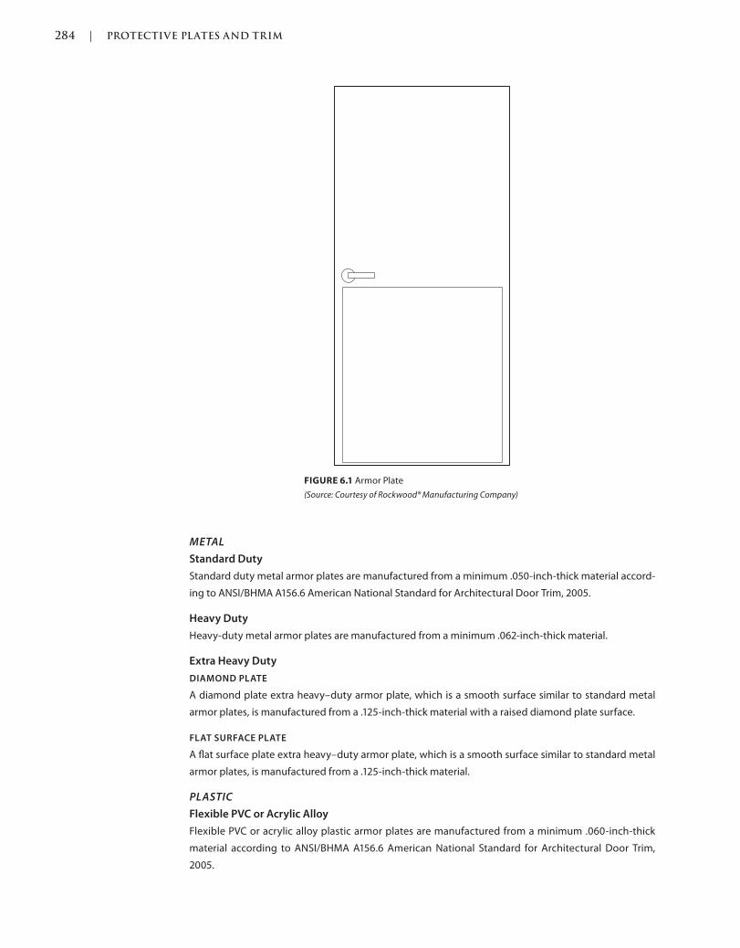
284 | PROTECTIVE PLATES AND TRIM
Trim: 215 x 276 mm c06.indd 02/27/2015 03:32:0:PM Page 284
METAL
Standard Duty
Standard duty metal armor plates are manufactured from a minimum .050-inch-thick material accord-
ing to ANSI/BHMA A156.6 American National Standard for Architectural Door Trim, 2005.
Heavy Duty
Heavy-duty metal armor plates are manufactured from a minimum .062-inch-thick material.
Extra Heavy Duty
DIAMOND PLATE
A diamond plate extra heavy–duty armor plate, which is a smooth surface similar to standard metal
armor plates, is manufactured from a .125-inch-thick material with a raised diamond plate surface.
FLAT SURFACE PLATE
A flat surface plate extra heavy–duty armor plate, which is a smooth surface similar to standard metal
armor plates, is manufactured from a .125-inch-thick material.
PLASTIC
Flexible PVC or Acrylic Alloy
Flexible PVC or acrylic alloy plastic armor plates are manufactured from a minimum .060-inch-thick
material according to ANSI/BHMA A156.6 American National Standard for Architectural Door Trim,
2005.
FIGURE 6.1 Armor Plate
(Source: Courtesy of Rockwood® Manufacturing Company)

PROTECTIVE PLATES AND TRIM | 285
c06.indd 02/27/2015 03:32:0:PM Page 285Trim: 215 x 276 mm
Laminate
Standard-duty plastic armor plates are manufactured from a minimum 1/8-inch-thick material
according to ANSI/BHMA A156.6 American National Standard for Architectural Door Trim, 2005.
Materials
Armor plates can be manufactured from aluminum, brass, plastic, or stainless steel. Armor plates
should comply with Materials for Product Category J100 as described in the current version of ANSI/
BHMA A156.6 American National Standard for Architectural Door Trim.
TYPES
Armor plates come in one type, which can be manufactured from different materials, in various sizes,
using different mounting methods. The current version of ANSI/BHMA A156.6 American National Stan-
dard for Architectural Door Trim describes armor plates as Product Category J100.
Metal
A metal armor plate is categorized as J101 in ANSI/BHMA A156.6 American National Standard for Archi-
tectural Door Trim, 2005.
A plastic armor plate is categorized as J105 in ANSI/BHMA A156.6 American National Standard for Archi-
tectural Door Trim, 2005.
SIZES
Height and Width
Although the sizes may vary depending on interpretation, armor plates are typically specified by height
and width and are installed 1 1/2 inches less than the door width on the pull side of the door and 2
inches less than the door width on the push side of the door. These dimensions are for doors installed in
standard door frames that have standard 5/8-inch stops projecting into the door opening clear width.
The deduction of 2 inches on the push side is so the plate does not bind with the frame stops and the
deduction of 1 1/2 inches on the pull side is so the fasteners have sufficient space to secure to.
FIGURE 6.2 Diamond Plate Surface
(Source: Courtesy of Rockwood® Manufacturing Company)
286 | PROTECTIVE PLATES AND TRIM
Trim: 215 x 276 mm c06.indd 02/27/2015 03:32:0:PM Page 286
Armor plates are typically any height over 12 inches, which is the typical maximum height of a kickplate,
and 48 inches, which is above any standard-height cart or object that might move through the door
opening.
Thickness
Standard armor plates are available in various thicknesses depending on the intended use and frequency.
OPTIONS
Anti-Microbial Coating
Armor plates are available with an optional anti-microbial coating. The coating is a silver ion–based
clear coating that helps stop the spread of bacteria. Although there are silver ions, they are not visible
to the eye and a brass or bronze finish shows its true color through the coating. Silver has been used
throughout history to help reduce the spread of bacteria and infection: Why not put it on doors and
hardware that is touched over and over again by numerous people in a day?
Countersunk Holes
Armor plates might not be manufactured standard with countersunk holes, and this should be specified
if desired. If the holes are not countersunk, the head of the screws will protrude off the face of the door,
whereas countersunk holes will allow the head of the screws to install flush with the face of the armor plate.
Cutouts
Some doors might have louvers, a lockset, or other conflicting hardware where an armor plate might
be installed. Therefore, manufacturers will provide special cutouts, if ordered properly. Otherwise, field
cutting might not give the accuracy required for the conflicting hardware devices to operate properly
or at all.
Edges
BEVELED
Armor plates have the option for beveled edges. In addition to being an aesthetic preference, beveled
edges are softened at the end to a 45-degree angle back to the door instead of having a 90-degree
square edge. Although four beveled edges are available as an option, three beveled edges are also
available for those who are not particular about the bottom edge. The bottom edge of an armor plate is
typically flush with the bottom of the door and is beveled, leaving it at a square edged, 90-degree angle.
SQUARE
Armor plates might have the option for all four square edges. As described above, three beveled edges
are an option, leaving at least one, the bottom edge of the armor plate, a square edged. In addition to
being an aesthetic preference, square edges are a 90-degree cut back to the door. Caution should be
used, however, as the edges can be sharp.
Engraving
Manufacturers have the ability to engrave armor plates. Engraving requests might include a room
number in an office, educational, or healthcare facility, or possibly an exit sign with photoluminescent
properties.
Labeling
Until a change in codes occurred, which forced a change in manufacturing and testing requirements,
protection plates higher than 16 inches from the bottom edge of the door could not be installed on
PROTECTIVE PLATES AND TRIM | 287
c06.indd 02/27/2015 03:32:0:PM Page 287Trim: 215 x 276 mm
fire rated doors. Now, some manufacturers have tested their plates for installation on fire-rated doors
no matter what the height of the plate or fire label of the door.
Shapes
A typical armor plate is square with squared corners, but some manufacturers offer shaped protection
plates, which allow for curves and designs to be incorporated into the shape.
QUANTITIES
Armor plates are furnished in single quantities and should be specified one for each door surface
required.
APPLICATIONS
Surface Mounted
Armor plates are surface-mounted, typically on the push side face of a door.
Angle Plate
BOTTOM
An angle plate also covers one or two sides of the door in addition to the face of the door.
ONE SIDED
A one-sided angle plate wraps around one side edge of the door in addition to the face of the door.
TWO SIDED
A two-sided angle plate wraps around both side edges of the door in addition to the face of the door.
INSTALLATION
Armor plates are typically installed on the push side face of a door.
Fasteners
Armor plates are typically installed with screw fasteners, which are available for installation on wood or
metal door materials. An armor plate typically has countersunk screw holes around the perimeter, which
should comply with ANSI/BHMA A156.6 American National Standard for Architectural Door Trim, 2005.
COUNTERSUNK
Armor plates might not be manufactured standard with countersunk holes and this should be specified
if desired. If the holes are not countersunk, the head of the screws will protrude off the face of the door,
whereas countersunk holes will allow the head of the screws to install flush with the face of the armor plate.
SELFADHESIVE
Armor plates are available with a self-adhesive double-faced tape option in lieu of screw fasteners.
If self-adhesive tape is used, the armor plate typically will not have any screw holes as with a typical
installation.
SURFACE MOUNTED
Armor plates might not be manufactured standard with countersunk holes. The screws would be installed
surface-mounted on the plate with the head of the screws protruding off the face of the armor plate.
Locations
Armor plates should be installed on the bottom half of the push side of a door surface to protect the
door from objects moving through the door opening that might cause damage to the door surface.

288 | PROTECTIVE PLATES AND TRIM
Trim: 215 x 276 mm c06.indd 02/27/2015 03:32:0:PM Page 288
Preparations
Armor plate preparations are not required if self-tapping screws are not being used, and the screw
holes are drilled and tapped in the field by the installer.
DOOR EDGE GUARDS
Also Known As: Door Edge Plates, Edge Guards, Edge Plates
DESCRIPTION
Door edge guards are typically installed at the edges of a door that require protection from an object
moving through the door opening that might cause damage to the edges of the door. The edge guard
would need to be ordered and manufactured as a square angle or beveled, depending on the door edge.
PROPERTIES
Finishes
Door edge guards are typically available in a limited number of architectural finishes and should comply
with the current version of ANSI/BHMA A156.18 American National Standard for Materials and Finishes.
Grades
Door edge guards are not categorized in grades but should comply with standards in Workmanship as
described for Product Category J200 in the current version of ANSI/BHMA A156.6 American National
Standard for Architectural Door Trim.
Door edge guards are available in different duties, which depend on the thickness and type of material
used.
Materials
Door edge plates are typically manufactured of aluminum, brass, or stainless steel material. Door edge
guards should comply with Materials for Product Category J200 as described in the current version of
ANSI/BHMA A156.6 American National Standard for Architectural Door Trim.
TYPES
Door edge guards are available in various types. The current version of ANSI/BHMA A156.6 American
National Standard for Architectural Door Trim describes armor plates as Product Category J200.
Mortise
Mortise edge guards are mortised into the door.
ANGLE
This door edge configuration is mortised into the edge of the door, making it flush with the door. It
is manufactured for a square-edged door and wraps around the edge and one face of the door. If a
separate face protection plate is used, such as an armor plate, it butts up against or installs over the
edge of the door edge guard. J204 is categorized in ANSI/BHMA A156.6 American National Standard for
Architectural Door Trim, 2005.
This door edge configuration is mortised into the edge of the door, making it flush with the door. It
is manufactured for a bevel-edged door and wraps around the edge and one face of the door. If a
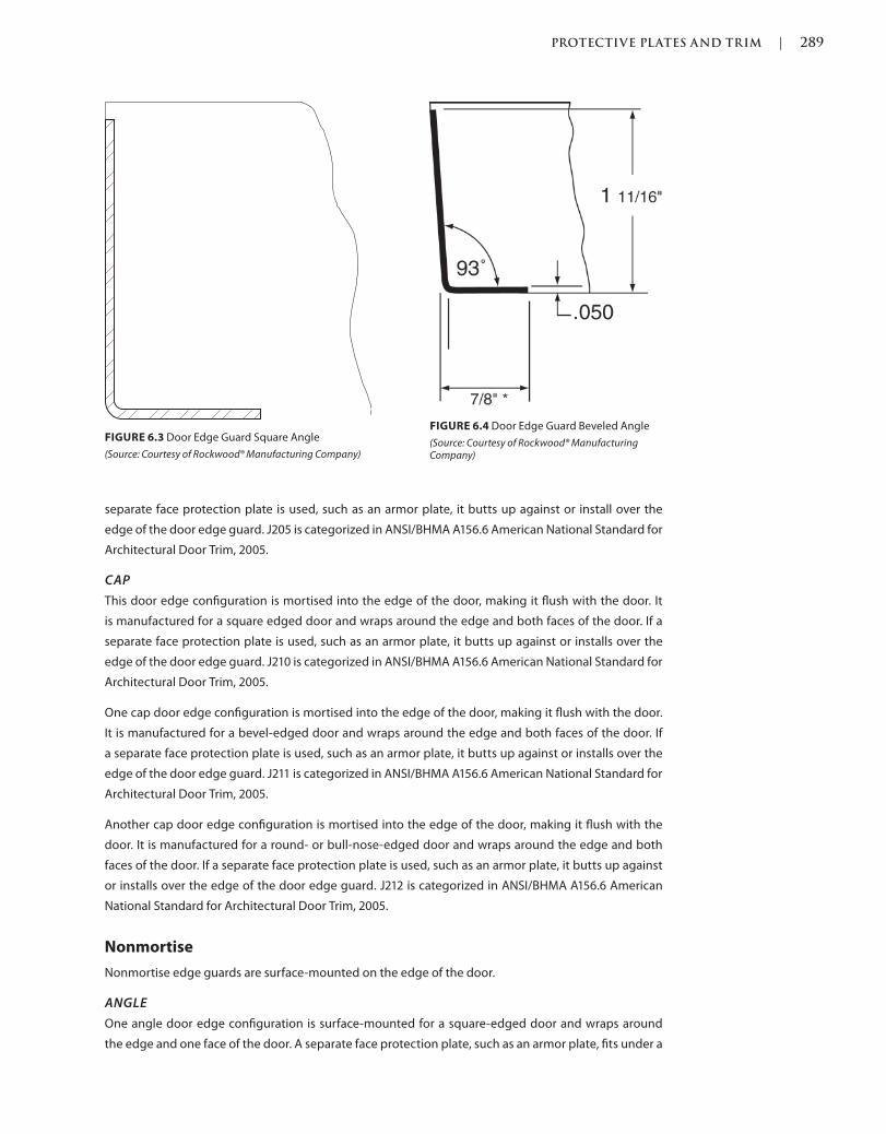
PROTECTIVE PLATES AND TRIM | 289
c06.indd 02/27/2015 03:32:0:PM Page 289Trim: 215 x 276 mm
separate face protection plate is used, such as an armor plate, it butts up against or install over the
edge of the door edge guard. J205 is categorized in ANSI/BHMA A156.6 American National Standard for
Architectural Door Trim, 2005.
CAP
This door edge configuration is mortised into the edge of the door, making it flush with the door. It
is manufactured for a square edged door and wraps around the edge and both faces of the door. If a
separate face protection plate is used, such as an armor plate, it butts up against or installs over the
edge of the door edge guard. J210 is categorized in ANSI/BHMA A156.6 American National Standard for
Architectural Door Trim, 2005.
One cap door edge configuration is mortised into the edge of the door, making it flush with the door.
It is manufactured for a bevel-edged door and wraps around the edge and both faces of the door. If
a separate face protection plate is used, such as an armor plate, it butts up against or installs over the
edge of the door edge guard. J211 is categorized in ANSI/BHMA A156.6 American National Standard for
Architectural Door Trim, 2005.
Another cap door edge configuration is mortised into the edge of the door, making it flush with the
door. It is manufactured for a round- or bull-nose-edged door and wraps around the edge and both
faces of the door. If a separate face protection plate is used, such as an armor plate, it butts up against
or installs over the edge of the door edge guard. J212 is categorized in ANSI/BHMA A156.6 American
National Standard for Architectural Door Trim, 2005.
Nonmortise
Nonmortise edge guards are surface-mounted on the edge of the door.
ANGLE
One angle door edge configuration is surface-mounted for a square-edged door and wraps around
the edge and one face of the door. A separate face protection plate, such as an armor plate, fits under a
FIGURE 6.4 Door Edge Guard Beveled Angle
(Source: Courtesy of Rockwood® Manufacturing Company)
FIGURE 6.3 Door Edge Guard Square Angle
(Source: Courtesy of Rockwood® Manufacturing Company)
290 | PROTECTIVE PLATES AND TRIM
Trim: 215 x 276 mm c06.indd 02/27/2015 03:32:0:PM Page 290
raise at the edge of the door edge guard. J201 is categorized in ANSI/BHMA A156.6 American National
Standard for Architectural Door Trim, 2005.
Another angle door edge configuration is surface-mounted for a bevel-edged door and wraps around
the edge and one face of the door. A separate face protection plate, such as an armor plate, fits under a
raise at the edge of the door edge guard. J201 is categorized in ANSI/BHMA A156.6 American National
Standard for Architectural Door Trim, 2005.
CAP
This door edge configuration is surface-mounted for a square-edged door and wraps around the edge
and both faces of the door. Separate face protection plates, such as armor plates, fit under the raises at
both edges of the door edge guard. J207 is categorized in ANSI/BHMA A156.6 American National Stan-
dard for Architectural Door Trim, 2005.
Some manufacturers might have the option to add an overlapping astragal to this door edge type for
pairs of doors.
Another door edge configuration is surface-mounted for a bevel edged door and wraps around the
edge and both faces of the door. Separate face protection plates, such as armor plates, fit under the
raises at both edges of the door edge guard. J208 is categorized in ANSI/BHMA A156.6 American
National Standard for Architectural Door Trim, 2005.
Some manufacturers might have the option to add an overlapping astragal to this door edge type for
pairs of doors.
Another door edge configuration is surface-mounted for a round- or bull-nose-edged door and wraps
around the edge and both faces of the door. Separate face protection plates, such as armor plates, fit
under both raised edges of the door edge guard. J209 is categorized in ANSI/BHMA A156.6 American
National Standard for Architectural Door Trim, 2005.
SIZES
Height and Width
Door edge guards are available in standard door heights but can be specified for a custom net door
height. Door edge guards are typically available for 1 3/4-inch-thick doors but can be manufactured for
other thicknesses, depending on what is available from the the manufacturer.
Thickness
Door edge guard materials are typically manufactured in a. 050-inch thickness.
OPTIONS
Anti-Microbial Coating
Door edge guards are available with an optional anti-microbial coating. The coating is a silver ion–
based clear coating that helps stop the spread of bacteria. Although there are silver ions, they are not
visible to the eye and a brass or bronze finish shows its true color through the coating. Silver has been
used throughout history to help reduce the spread of bacteria and infection: Why not put it on doors
and hardware that is touched over and over again by numerous people in a day?
Countersunk Holes
Door edge guards might not be manufactured in standard versions with countersunk holes and this
should be specified if desired. If the holes are not countersunk, the head of the screws will protrude off
PROTECTIVE PLATES AND TRIM | 291
c06.indd 02/27/2015 03:32:0:PM Page 291Trim: 215 x 276 mm
the face of the door, whereas countersunk holes will allow the head of the screws to install flush with
the face of the armor plate.
Cutouts
Some doors with door edge guards installed might have flushbolts, locksets, lock strikes, hinges, or
other conflicting hardware where a door edge guard might be installed. Therefore, manufacturers will
make special cutouts if ordered properly. If not, field cutting might not give the accuracy required for
the conflicting hardware devices to operate properly or at all.
Labeling
Some manufacturers have tested their door edge guards to be installed on fire rated doors up to three
hours.
Shapes
As described in the Types section, an edge guard could be square edged, bevel edged, round, or bull-
nosed, and wrap around the side and either one or both faces of the door. Both face and wrap-around
door edge guards might have the option to add an astragal.
QUANTITIES
Door edge guards are furnished in single quantities and should be specified one for each door edge
required.
APPLICATIONS
Mortised
Door edge guards are available to be mortised into the edge and face or faces of the edge of the door.
Surface Mounted
Door edge guards are available to be surface-mounted onto the edge and face or faces of the edge of
the door.
INSTALLATION
Door edge guards are typically installed at the edge of a door and wrap around either one or both faces
of the door.
Fasteners
Door edge guards are typically installed with screw fasteners, which are available for installation
on wood or metal door materials. Door edge guards would typically have countersunk screw holes,
which should comply with ANSI/BHMA A156.6 American National Standard for Architectural Door
Trim, 2005.
Locations
Door edge guards should be installed at the edge of the entire height of a door, on either the hanging
or latching side, or both.
Preparations
Door edge guard preparations are not required if self-tapping screws are not being used and the screw
holes can be drilled and tapped in the field by the installer.
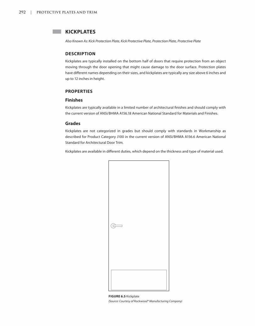
292 | PROTECTIVE PLATES AND TRIM
Trim: 215 x 276 mm c06.indd 02/27/2015 03:32:0:PM Page 292
KICKPLATES
Also Known As: Kick Protection Plate, Kick Protective Plate, Protection Plate, Protective Plate
DESCRIPTION
Kickplates are typically installed on the bottom half of doors that require protection from an object
moving through the door opening that might cause damage to the door surface. Protection plates
have different names depending on their sizes, and kickplates are typically any size above 6 inches and
up to 12 inches in height.
PROPERTIES
Finishes
Kickplates are typically available in a limited number of architectural finishes and should comply with
the current version of ANSI/BHMA A156.18 American National Standard for Materials and Finishes.
Grades
Kickplates are not categorized in grades but should comply with standards in Workmanship as
described for Product Category J100 in the current version of ANSI/BHMA A156.6 American National
Standard for Architectural Door Trim.
Kickplates are available in different duties, which depend on the thickness and type of material used.
FIGURE 6.5 Kickplate
(Source: Courtesy of Rockwood® Manufacturing Company)
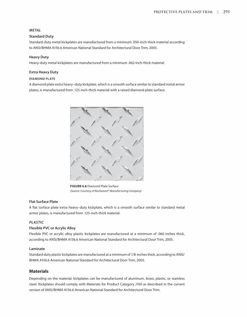
PROTECTIVE PLATES AND TRIM | 293
c06.indd 02/27/2015 03:32:0:PM Page 293Trim: 215 x 276 mm
METAL
Standard Duty
Standard duty metal kickplates are manufactured from a minimum .050-inch-thick material according
to ANSI/BHMA A156.6 American National Standard for Architectural Door Trim, 2005.
Heavy Duty
Heavy-duty metal kickplates are manufactured from a minimum .062-inch-thick material.
Extra Heavy Duty
DIAMOND PLATE
A diamond plate extra heavy–duty kickplate, which is a smooth surface similar to standard metal armor
plates, is manufactured from .125-inch-thick material with a raised diamond plate surface.
Flat Surface Plate
A flat surface plate extra heavy–duty kickplate, which is a smooth surface similar to standard metal
armor plates, is manufactured from .125-inch-thick material.
PLASTIC
Flexible PVC or Acrylic Alloy
Flexible PVC or acrylic alloy plastic kickplates are manufactured at a minimum of .060 inches thick,
according to ANSI/BHMA A156.6 American National Standard for Architectural Door Trim, 2005.
Laminate
Standard duty plastic kickplates are manufactured at a minimum of 1/8-inches thick, according to ANSI/
BHMA A156.6 American National Standard for Architectural Door Trim, 2005.
Materials
Depending on the material, kickplates can be manufactured of aluminum, brass, plastic, or stainless
steel. Kickplates should comply with Materials for Product Category J100 as described in the current
version of ANSI/BHMA A156.6 American National Standard for Architectural Door Trim.
FIGURE 6.6 Diamond Plate Surface
(Source: Courtesy of Rockwood® Manufacturing Company)
294 | PROTECTIVE PLATES AND TRIM
Trim: 215 x 276 mm c06.indd 02/27/2015 03:32:0:PM Page 294
TYPES
Kickplates have one type, which can be manufactured from different materials, in various sizes, using
different mounting methods. The current version of ANSI/BHMA A156.6 American National Standard for
Architectural Door Trim describes armor plates as Product Category J100.
Metal
A metal kickplate is categorized as J102 in ANSI/BHMA A156.6 American National Standard for
Architectural Door Trim, 2005.
Plastic
A plastic kickplate is categorized as J106 in ANSI/BHMA A156.6 American National Standard for
Architectural Door Trim, 2005.
SIZES
Height and Width
Kickplates are typically specified in height by width and are installed 1 1/2 inches less than the door
width on the pull side of the door and 2 inches less than the door width on the push side of the door.
These dimensions are for doors installed in standard door frames that have standard 5/8-inch stops
projecting into the door opening clear width. The deduction of 2 inches on the push side is so the plate
does not bind with the frame stops and the deduction of 1 1/2 inches on the pull side is so the fasteners
have sufficient space to secure to.
Although the sizes may vary depending on interpretation, kickplates are typically any height over 6
inches, which is the typical maximum height of a mop plate, and 12 inches.
Thickness
Standard kickplates are available in various thicknesses depending on the intended use and
frequency.
OPTIONS
Anti-Microbial Coating
Kickplates are available with an optional anti-microbial coating. The coating is a silver ion–based clear
coating that helps stop the spread of bacteria. Although there are silver ions, they are not visible to
the eye and a brass or bronze finish shows its true color through the coating. Silver has been used
throughout history to help reduce the spread of bacteria and infection: Why not put it on doors and
hardware that is touched over and over again by numerous different people in a day?
Countersunk Holes
Kickplates might not be manufactured standard with countersunk holes and this should be specified if
desired. If the holes are not countersunk, the head of the screws will protrude off the face of the door,
whereas countersunk holes will allow the head of the screws to install flush with the face of the armor
plate.
Cutouts
Some doors might have louvers or other conflicting hardware where a kickplate might be installed.
Therefore, manufacturers will make special cutouts, if ordered properly. If not, field cutting might not
give the accuracy required for the conflicting hardware devices to operate properly or at all.
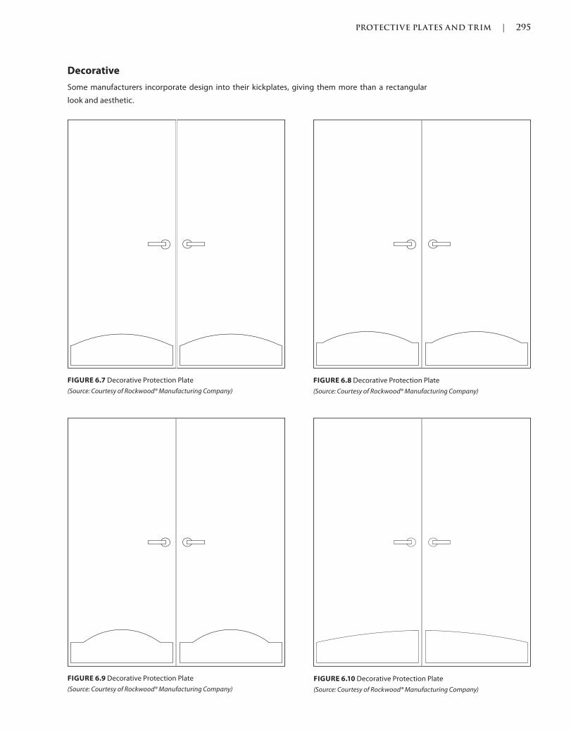
PROTECTIVE PLATES AND TRIM | 295
c06.indd 02/27/2015 03:32:0:PM Page 295Trim: 215 x 276 mm
Decorative
Some manufacturers incorporate design into their kickplates, giving them more than a rectangular
look and aesthetic.
FIGURE 6.7 Decorative Protection Plate
(Source: Courtesy of Rockwood® Manufacturing Company)
FIGURE 6.8 Decorative Protection Plate
(Source: Courtesy of Rockwood® Manufacturing Company)
FIGURE 6.10 Decorative Protection Plate
(Source: Courtesy of Rockwood® Manufacturing Company)
FIGURE 6.9 Decorative Protection Plate
(Source: Courtesy of Rockwood® Manufacturing Company)
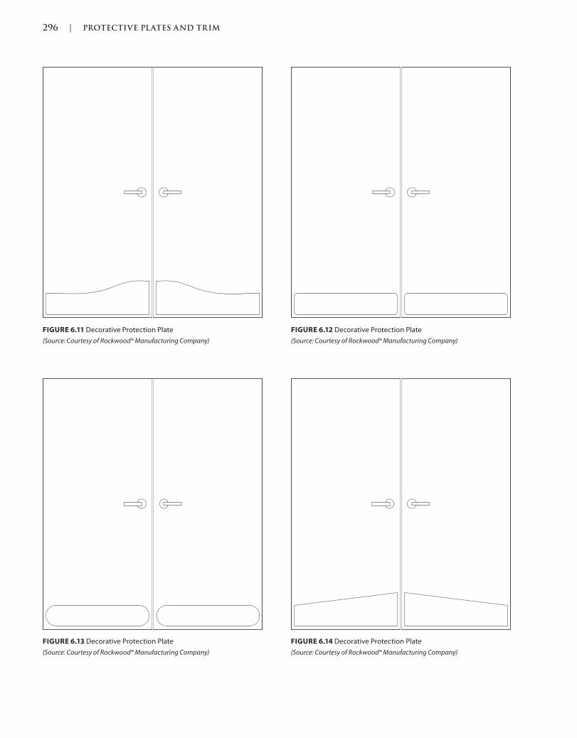
296 | PROTECTIVE PLATES AND TRIM
Trim: 215 x 276 mm c06.indd 02/27/2015 03:32:0:PM Page 296
FIGURE 6.11 Decorative Protection Plate
(Source: Courtesy of Rockwood® Manufacturing Company)
FIGURE 6.12 Decorative Protection Plate
(Source: Courtesy of Rockwood® Manufacturing Company)
FIGURE 6.14 Decorative Protection Plate
(Source: Courtesy of Rockwood® Manufacturing Company)
FIGURE 6.13 Decorative Protection Plate
(Source: Courtesy of Rockwood® Manufacturing Company)
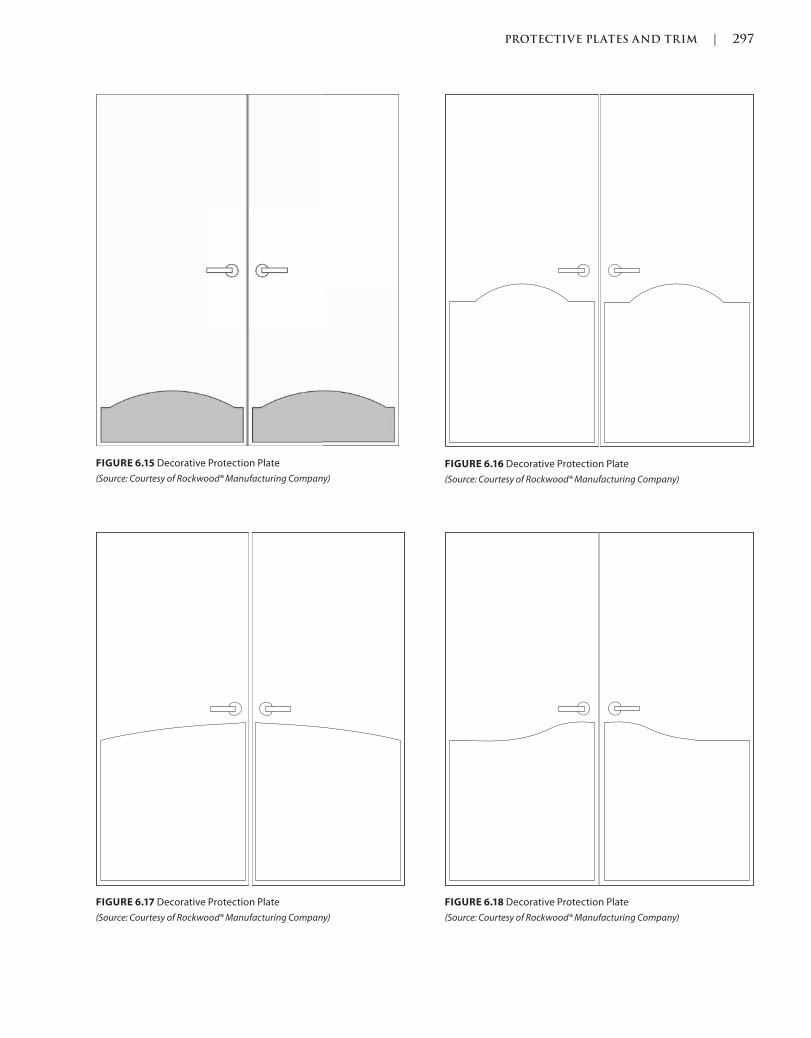
PROTECTIVE PLATES AND TRIM | 297
c06.indd 02/27/2015 03:32:0:PM Page 297Trim: 215 x 276 mm
FIGURE 6.18 Decorative Protection Plate
(Source: Courtesy of Rockwood® Manufacturing Company)
FIGURE 6.15 Decorative Protection Plate
(Source: Courtesy of Rockwood® Manufacturing Company)
FIGURE 6.16 Decorative Protection Plate
(Source: Courtesy of Rockwood® Manufacturing Company)
FIGURE 6.17 Decorative Protection Plate
(Source: Courtesy of Rockwood® Manufacturing Company)
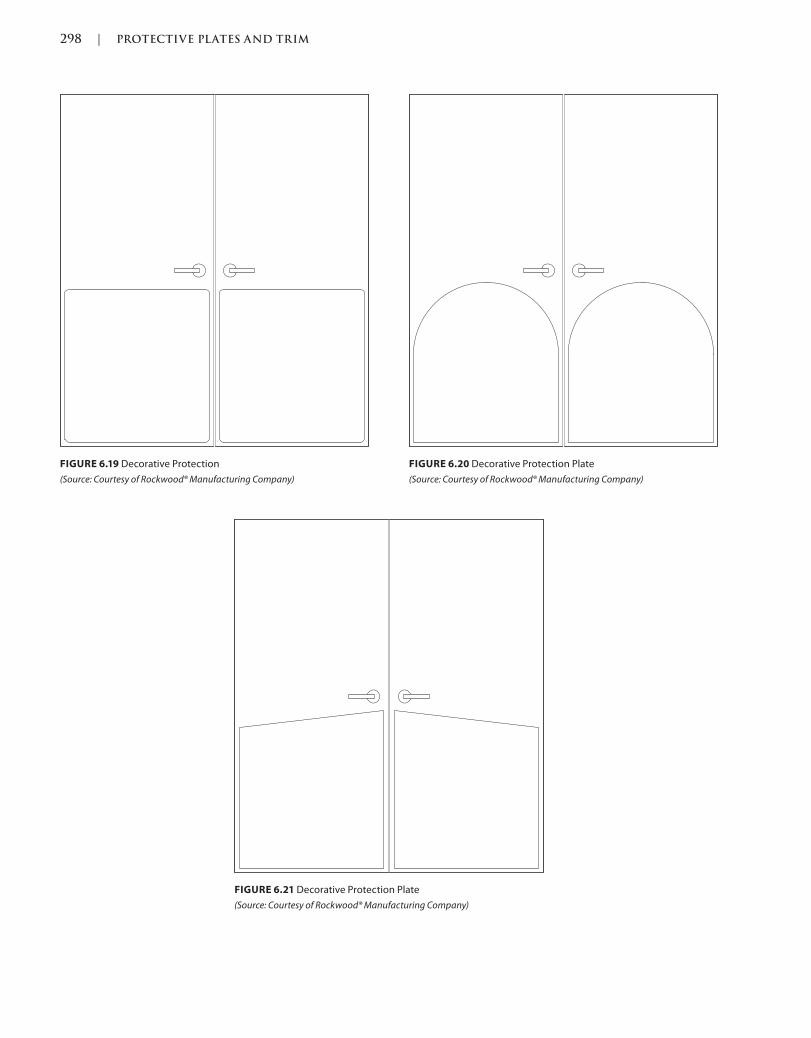
298 | PROTECTIVE PLATES AND TRIM
Trim: 215 x 276 mm c06.indd 02/27/2015 03:32:0:PM Page 298
FIGURE 6.21 Decorative Protection Plate
(Source: Courtesy of Rockwood® Manufacturing Company)
FIGURE 6.19 Decorative Protection
(Source: Courtesy of Rockwood® Manufacturing Company)
FIGURE 6.20 Decorative Protection Plate
(Source: Courtesy of Rockwood® Manufacturing Company)

PROTECTIVE PLATES AND TRIM | 299
c06.indd 02/27/2015 03:32:0:PM Page 299Trim: 215 x 276 mm
Edges
BEVELED
Kickplates have the option for beveled edges. In addition to being an aesthetic preference, beveled
edges are softened at the end to a 45-degree angle back to the door instead of having a 90-degree
square edge. Although four beveled edges are available as an option, three beveled edges are also
available for those who are not particular about the bottom edge. The bottom edge of a kickplate is typ-
ically flush with the bottom of the door and is beveled, leaving it at a square-edged, 90-degree angle.
SQUARE
Kickplates might have the option for four square edges. As described above, three beveled edges are
an option, leaving at least one, the bottom edge of the armor plate, square edged. In addition to being
an aesthetic preference, square edges are a 90-degree cut back to the door. Caution should be used,
however, as the edges can be sharp.
Engraving
Manufacturers have the ability to engrave kickplates. Engraving requests might be a room number in
an office, educational, or healthcare facility, or possibly an exit sign with photoluminescent properties.
Labeling
Until a change in codes, which forced a change in manufacturing and testing requirements, protection
plates higher than 16 inches from the bottom edge of the door could not be installed on fire rated
doors. Now, some manufacturers have tested their plates, so they can be installed on fire rated doors
no matter what the height of the plate or fire label of the door.
Shapes
A typical kickplate is rectangular with square corners, but some manufacturers offer shaped protection
plates, which allow for curves and designs to be incorporated into the shape.
QUANTITIES
Kickplates are furnished in single quantities and should be specified one for each door surface required.
APPLICATIONS
Surface Mounted
Kickplates are surface-mounted, typically on the push side face of a door.
Angle Plate
BOTTOM
An angle plate also covers one or two sides of the door in addition to the face of the door.
ONE SIDED
A one-sided angle plate wraps around one side edge of the door in addition to the face of the door.
TWO SIDED
A two-sided angle plate wraps around both side edges of the door in addition to the face of the door.
INSTALLATION
Kickplates are typically installed on the push side face of a door.
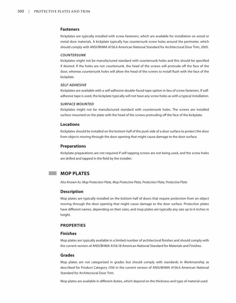
300 | PROTECTIVE PLATES AND TRIM
Trim: 215 x 276 mm c06.indd 02/27/2015 03:32:0:PM Page 300
Fasteners
Kickplates are typically installed with screw fasteners, which are available for installation on wood or
metal door materials. A kickplate typically has countersunk screw holes around the perimeter, which
should comply with ANSI/BHMA A156.6 American National Standard for Architectural Door Trim, 2005.
COUNTERSUNK
Kickplates might not be manufactured standard with countersunk holes and this should be specified
if desired. If the holes are not countersunk, the head of the screws will protrude off the face of the
door, whereas countersunk holes will allow the head of the screws to install flush with the face of the
kickplate.
SELFADHESIVE
Kickplates are available with a self-adhesive double-faced tape option in lieu of screw fasteners. If self-
adhesive tape is used, the kickplate typically will not have any screw holes as with a typical installation.
SURFACE MOUNTED
Kickplates might not be manufactured standard with countersunk holes. The screws are installed
surface-mounted on the plate with the head of the screws protruding off the face of the kickplate.
Locations
Kickplates should be installed on the bottom half of the push side of a door surface to protect the door
from objects moving through the door opening that might cause damage to the door surface.
Preparations
Kickplate preparations are not required if self-tapping screws are not being used, and the screw holes
are drilled and tapped in the field by the installer.
MOP PLATES
Also Known As: Mop Protection Plate, Mop Protective Plate, Protection Plate, Protective Plate
Description
Mop plates are typically installed on the bottom half of doors that require protection from an object
moving through the door opening that might cause damage to the door surface. Protection plates
have different names, depending on their sizes, and mop plates are typically any size up to 6 inches in
height.
PROPERTIES
Finishes
Mop plates are typically available in a limited number of architectural finishes and should comply with
the current version of ANSI/BHMA A156.18 American National Standard for Materials and Finishes.
Grades
Mop plates are not categorized in grades but should comply with standards in Workmanship as
described for Product Category J100 in the current version of ANSI/BHMA A156.6 American National
Standard for Architectural Door Trim.
Mop plates are available in different duties, which depend on the thickness and type of material used.
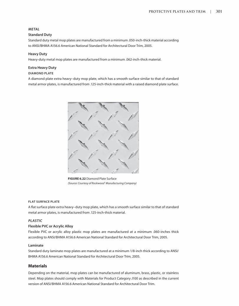
PROTECTIVE PLATES AND TRIM | 301
c06.indd 02/27/2015 03:32:0:PM Page 301Trim: 215 x 276 mm
METAL
Standard Duty
Standard duty metal mop plates are manufactured from a minimum .050-inch-thick material according
to ANSI/BHMA A156.6 American National Standard for Architectural Door Trim, 2005.
Heavy Duty
Heavy-duty metal mop plates are manufactured from a minimum .062-inch-thick material.
Extra Heavy Duty
DIAMOND PLATE
A diamond plate extra heavy–duty mop plate, which has a smooth surface similar to that of standard
metal armor plates, is manufactured from .125-inch-thick material with a raised diamond plate surface.
FIGURE 6.22 Diamond Plate Surface
(Source: Courtesy of Rockwood® Manufacturing Company)
FLAT SURFACE PLATE
A flat surface plate extra heavy–duty mop plate, which has a smooth surface similar to that of standard
metal armor plates, is manufactured from .125-inch-thick material.
PLASTIC
Flexible PVC or Acrylic Alloy
Flexible PVC or acrylic alloy plastic mop plates are manufactured at a minimum .060-inches thick
according to ANSI/BHMA A156.6 American National Standard for Architectural Door Trim, 2005.
Laminate
Standard duty laminate mop plates are manufactured at a minimum 1/8-inch thick according to ANSI/
BHMA A156.6 American National Standard for Architectural Door Trim, 2005.
Materials
Depending on the material, mop plates can be manufactured of aluminum, brass, plastic, or stainless
steel. Mop plates should comply with Materials for Product Category J100 as described in the current
version of ANSI/BHMA A156.6 American National Standard for Architectural Door Trim.
302 | PROTECTIVE PLATES AND TRIM
Trim: 215 x 276 mm c06.indd 02/27/2015 03:32:0:PM Page 302
TYPES
Mop plates have one type, which can be manufactured from different materials, at various sizes, and
using different mounting methods. The current version of ANSI/BHMA A156.6 American National
Standard for Architectural Door Trim describes armor plates as Product Category J100.
Metal
A metal mop plate is categorized as J103 in ANSI/BHMA A156.6 American National Standard for
Architectural Door Trim, 2005.
Plastic
A plastic mop plate is categorized as J107 in ANSI/BHMA A156.6 American National Standard for
Architectural Door Trim, 2005.
SIZES
Height and Width
Mop plates are typically specified in height by width and are installed 1 1/2 inches less than the door
width on the pull side of the door and 2 inches less than the door width on the push side of the door.
These dimensions are for doors installed in standard door frames that have standard 5/8-inch stops
projecting into the door opening clear width. The deduction of 2 inches on the push side is so the plate
does not bind with the frame stops and the deduction of 1 1/2 inches on the pull side is so the fasteners
have sufficient space to secure to.
Although the sizes may vary depending on interpretation, mop plates are typically any height up to 6
inches, which is the typical maximum height of a mop plate.
Thickness
Standard mop plates are available in various thicknesses depending on the intended use and frequency.
OPTIONS
Anti-Microbial Coating
Mop plates are available with an optional anti-microbial coating. The coating is a silver ion–based clear
coating that helps stop the spread of bacteria. Although there are silver ions, they are not visible to
the eye and a brass or bronze finish shows its true color through the coating. Silver has been used
throughout history to help reduce the spread of bacteria and infection: Why not put it on doors and
hardware that is touched over and over again by numerous people in a day?
Countersunk Holes
Mop plates might not be manufactured standard with countersunk holes and these should be specified
if desired. If the holes are not countersunk, the head of the screws will protrude off the face of the door,
whereas countersunk holes will allow the head of the screws to install flush with the face of the armor
plate.
Cutouts
Some doors might have louvers or other conflicting hardware where a mop plate might be installed.
Therefore, manufacturers will make special cutouts, if ordered properly. If not, field cutting might not
give the accuracy required for the conflicting hardware devices to operate properly or at all.
PROTECTIVE PLATES AND TRIM | 303
c06.indd 02/27/2015 03:32:0:PM Page 303Trim: 215 x 276 mm
Edges
BEVELED
Mop plates have the option for beveled edges. In addition to being an aesthetic preference, beveled
edges are softened at the end to a 45-degree angle back to the door instead of a 90-degree square
edge. Although four beveled edges are available as an option, three beveled edges are also available
for those who are not particular about the bottom edge. The bottom edge of a mop plate is typically
flush with the bottom of the door and is beveled, leaving it at a square edged, 90-degree angle.
SQUARE
Mop plates might have the option for all four square edges. As described above, three beveled edges
are an option, leaving at least one, the bottom edge of the armor plate, square edged. In addition to
being an aesthetic preference, square edges are a 90-degree cut back to the door. Caution should be
used, however, as the edges can be sharp.
Engraving
Manufacturers have the ability to engrave mop plates. An engraving request might be a room number in
an office, educational, or healthcare facility, or possibly an exit sign with photoluminescent properties.
Labeling
Until there was a change in codes, which forced a change in manufacturing and testing requirements,
protection plates higher than 16 inches from the bottom edge of the door could not be installed on fire
rated doors. Now, some manufacturers have tested their plates, so they can be installed on fire rated
doors no matter what the height of the plate or fire label of the door.
Shapes
A typical mop plate is rectangular with square corners, but some manufacturers offer shaped protection
plates, which allow for curves and designs to be incorporated into the shape.
QUANTITIES
Mop plates are furnished in single quantities and should be specified one for each door surface required.
APPLICATIONS
Surface Mounted
Mop plates are surface-mounted, typically on the push side face of a door.
Angle Plate
BOTTOM
An angle plate also covers one or two sides of the door in addition to the face of the door.
ONE SIDED
A one-sided angle plate wraps around one side edge of the door in addition to the face of the door.
TWO SIDED
A two-sided angle plate wraps around both side edges of the door in addition to the face of the door.
INSTALLATION
Mop plates are typically installed on the push side face of a door.

304 | PROTECTIVE PLATES AND TRIM
Trim: 215 x 276 mm c06.indd 02/27/2015 03:32:0:PM Page 304
Fasteners
Mop plates are typically installed with screw fasteners, which are available for installation on wood or
metal door materials. A mop plate typically has countersunk screw holes around the perimeter, which
should comply with ANSI/BHMA A156.6 American National Standard for Architectural Door Trim, 2005.
COUNTERSUNK
Mop plates might not be manufactured standard with countersunk holes and these should be specified
if desired. If the holes are not countersunk, the head of the screws will protrude off the face of the door,
whereas countersunk holes will allow the head of the screws to install flush with the face of the mop
plate.
SELFADHESIVE
Mop plates are available with a self-adhesive double-faced tape option in lieu of screw fasteners. If
self-adhesive tape is used, the mop plate typically does not have any screw holes as with a typical
installation.
SURFACE MOUNTED
Mop plates might not be manufactured standard with countersunk holes. The screws would be
installed surface-mounted on the plate with the head of the screws protruding off the face of the
mop plate.
Locations
Mop plates should be installed on the bottom half of the pull side of a door surface to protect the door
from mopping and cleaning liquids that might cause damage to the door’s surface.
Preparations
Mop plate preparations are not required if self-tapping screws are not being used, and the screw holes
are drilled and tapped in the field by the installer.
STRETCHER PLATES
Also Known As: Stretcher Protection Plate, Stretcher Protective Plate, Protection Plate, Protective Plate
FIGURE 6.23 Stretcher Plate
(Source: Courtesy of Rockwood® Manufacturing Company)
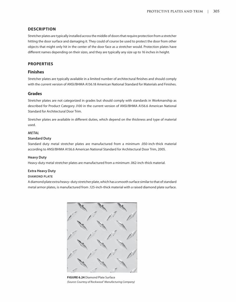
PROTECTIVE PLATES AND TRIM | 305
c06.indd 02/27/2015 03:32:0:PM Page 305Trim: 215 x 276 mm
DESCRIPTION
Stretcher plates are typically installed across the middle of doors that require protection from a stretcher
hitting the door surface and damaging it. They could of course be used to protect the door from other
objects that might only hit in the center of the door face as a stretcher would. Protection plates have
different names depending on their sizes, and they are typically any size up to 16 inches in height.
PROPERTIES
Finishes
Stretcher plates are typically available in a limited number of architectural finishes and should comply
with the current version of ANSI/BHMA A156.18 American National Standard for Materials and Finishes.
Grades
Stretcher plates are not categorized in grades but should comply with standards in Workmanship as
described for Product Category J100 in the current version of ANSI/BHMA A156.6 American National
Standard for Architectural Door Trim.
Stretcher plates are available in different duties, which depend on the thickness and type of material
used.
METAL
Standard Duty
Standard duty metal stretcher plates are manufactured from a minimum .050-inch-thick material
according to ANSI/BHMA A156.6 American National Standard for Architectural Door Trim, 2005.
Heavy Duty
Heavy-duty metal stretcher plates are manufactured from a minimum .062-inch-thick material.
Extra Heavy Duty
DIAMOND PLATE
A diamond plate extra heavy–duty stretcher plate, which has a smooth surface similar to that of standard
metal armor plates, is manufactured from .125-inch-thick material with a raised diamond plate surface.
FIGURE 6.24 Diamond Plate Surface
(Source: Courtesy of Rockwood® Manufacturing Company)
306 | PROTECTIVE PLATES AND TRIM
Trim: 215 x 276 mm c06.indd 02/27/2015 03:32:0:PM Page 306
FLAT SURFACE PLATE
A flat surface plate extra heavy–duty stretcher plate, which has a smooth surface similar to that of
standard metal armor plates, is manufactured from .125-inch-thick material.
PLASTIC
Flexible PVC or Acrylic Alloy
Flexible PVC or acrylic alloy plastic stretcher plates are manufactured at a minimum .060-inches thick
according to ANSI/BHMA A156.6 American National Standard for Architectural Door Trim, 2005.
Laminate
Standard-duty plastic stretcher plates are manufactured at a minimum 1/8-inch thick according to
ANSI/BHMA A156.6 American National Standard for Architectural Door Trim, 2005.
Materials
Depending on the material, stretcher plates can be manufactured of aluminum, brass, plastic, or
stainless steel. Stretcher plates should comply with Materials for Product Category J100 as described
in the current version of ANSI/BHMA A156.6 American National Standard for Architectural Door Trim.
Types
Stretcher plates have one type, which can be manufactured from different materials, in various sizes,
using different mounting methods.
SIZES
Height and Width
Stretcher plates are typically specified in height by width and are installed 1 1/2 inches less than the
door width on the pull side of the door and 2 inches less than the door width on the push side of the
door. These dimensions are for doors installed in standard door frames that have standard 5/8-inch
stops projecting into the door opening clear width. The deduction of 2 inches on the push side is so
the plate does not bind with the frame stops and the deduction of 1 1/2 inches on the pull side is so the
fasteners have sufficient space to secure to.
Although the sizes may vary depending on interpretation, stretcher plates are typically any height up
to 6 inches, which is the typical maximum height of a mop plate.
Thickness
Standard stretcher plates are available in various thicknesses depending on the intended use and
frequency of use.
OPTIONS
Anti-Microbial Coating
Stretcher plates are available with an optional anti-microbial coating. The coating is a silver ion–based
clear coating that helps stop the spread of bacteria. Although there are silver ions, they are not visible
to the eye and a brass or bronze finish shows its true color through the coating. Silver has been used
throughout history to help reduce the spread of bacteria and infection: Why not put it on doors and
hardware that is touched over and over again by numerous people in a day?
PROTECTIVE PLATES AND TRIM | 307
c06.indd 02/27/2015 03:32:0:PM Page 307Trim: 215 x 276 mm
Countersunk Holes
Stretcher plates might not be manufactured standard with countersunk holes and these should be
specified if desired. If the holes are not countersunk, the head of the screws will protrude off the face
of the door, whereas countersunk holes will allow the head of the screws to install flush with the face
of the armor plate.
Cutouts
Some doors might have louvers or other conflicting hardware where a mop plate might be installed.
As such, manufacturers will make special cutouts if ordered properly. If not, field cutting might not give
the accuracy required for the conflicting hardware devices to operate properly or at all.
Edges
BEVELED
Stretcher plates have the option for beveled edges. In addition to being an aesthetic preference, beveled
edges are softened at the end to a 45-degree angle back to the door instead of a 90-degree square
edge. Although four beveled edges are available as an option, three beveled edges are also available
for those who are not particular about the bottom edge. The bottom edge of a mop plate is typically
flush with the bottom of the door and is beveled, leaving it at a square-edged, 90-degree angle.
SQUARE
Stretcher plates might have the option for all four square edges. As described above, three beveled
edges are an option, leaving at least one, the bottom edge of the armor plate, square edged. In addition
to being an aesthetic preference, square edges are a 90-degree cut back to the door. Caution should be
used, however, as the edges can be sharp.
Engraving
Manufacturers have the ability to engrave stretcher plates. An engraving request might be a room number
in an office, educational, or healthcare facility, or possibly an exit sign with photoluminescent properties.
Labeling
Until a change in codes occurred, which forced a change in manufacturing and testing requirements,
protection plates higher than 16 inches from the bottom edge of the door could not be installed on fire
rated doors. Now, some manufacturers have tested their plates, so they can be installed on fire rated
doors no matter what the height of the plate or fire label of the door.
Shapes
A typical stretcher plate is rectangular with square corners, but some manufacturers offer shaped
protection plates, which allow for curves and designs to be incorporated into the shape.
QUANTITIES
Stretcher plates are furnished in single quantities and should be specified one for each door surface
required.
APPLICATIONS
Surface Mounted
Stretcher plates are typically surface-mounted on the push side face of a door.
308 | PROTECTIVE PLATES AND TRIM
Trim: 215 x 276 mm c06.indd 02/27/2015 03:32:0:PM Page 308
INSTALLATION
Stretcher plates are typically installed on the push side face of a door.
Fasteners
Stretcher plates are typically installed with screw fasteners, which are available for installation on wood
or metal door materials. A stretcher plate typically has countersunk screw holes around the perimeter,
which should comply with ANSI/BHMA A156.6 American National Standard for Architectural Door Trim,
2005.
COUNTERSUNK
Stretcher plates might not be manufactured standard with countersunk holes and these should be
specified if desired. If the holes are not countersunk, the head of the screws will protrude off the face
of the door, whereas countersunk holes will allow the head of the screws to install flush with the face
of the stretcher plate.
SELFADHESIVE
Stretcher plates are available with a self-adhesive double-faced tape option in lieu of screw fasteners.
If self-adhesive tape is used, the stretcher plate typically will not have any screw holes as with a typical
installation.
SURFACE MOUNTED
Stretcher plates might not be manufactured standard with countersunk holes. The screws would be
installed surface-mounted on the plate with the head of the screws protruding off of the face of the
stretcher plate.
Locations
Stretcher plates should be installed on the bottom half of the pull side of a door surface to protect the
door from mopping and cleaning liquids that might cause damage to the door’s surface.
Preparations
Stretcher plate preparations are not required if self-tapping screws are not being used, and the screw
holes would be drilled and tapped in the field by the installer.
REFERENCES
Codes and standards are available to set the minimum requirements of door openings (see the
Introduction of this book for more information). Some jurisdictions have specific codes and standards,
which were either modified from another existing code or created for their own use.
Language and section numbers can change slightly or drastically when the codes are updated. Look for
an outline, if available, of the changes that took place in the respective update.
CODES
International Building Code (IBC)
The following are chapter of a modified or fully adopted version of the International Building Code that
refer to protection plates and trim items or door hardware in general:
Chapter 7: Fire and Smoke Protection Features
Section 716 Opening Protectives
PROTECTIVE PLATES AND TRIM | 309
c06.indd 02/27/2015 03:32:0:PM Page 309Trim: 215 x 276 mm
Chapter 10: Means of Egress
Section 1008: Doors, Gates and Turnstiles
Chapter 17: Special Inspections and Tests
Section 1710 Preconstruction Load Tests
Chapter 26: Plastic
Section 2603 Foam Plastic Insulation
National Fire Protection Association (NFPA) 101: Life Safety Code
The following is a chapter of a modified or fully adopted version of the NFPA 101: Life Safety Code that
refers to protection plates and trim items or door hardware in general:
Chapter 7: Means of Egress
STANDARDS
ADA Accessibility Guidelines for Buildings and Facilities (ADAAG)
The following is a chapter of a modified or fully adopted version of the ADA Accessibility Guidelines
for Buildings and Facilities, that refers to protection plates and trim items or door hardware in general:
Chapter 4: Accessible Routes
ASTM International (ASTM)
There are hundreds of ASTM International testing standards that are related to doors and door
hardware, from material and assembly testing to installation and application testing.
Door and Hardware Institute (DHI)
The following are technical documents available for reference that refer to protection plates and trim
items or door hardware in general:
Abbreviations and Symbols
Basic Architectural Hardware
Hardware for Healthcare Facilities
Installation Guide for Doors and Hardware
Processing Hardware for Custom Aluminum Entrances
Recommended Locations for Builders Hardware Custom Steel Doors & Frames
Recommended Locations for Architectural Hardware for Standard Steel Doors & Frames
Recommended Locations for Architectural Hardware for Flush Wood Doors
Recommended Procedures for Processing Hardware Schedules and Templates
Sequence and Format for the Hardware Schedule
Tech-Talk ASD-1 Aluminum Storefront Doors
Tech-Talk PH-1 Protective Hardware
Tech-Talk SP-1 Hardware Specification Writing
International Code Council A117.1 Accessible and Usable Buildings and
Facilities, (ICC)
The following is a chapter of a modified or fully adopted version of the ICC A117.1 Accessible and Usable
Buildings and Facilities that refers to protection plates and trim items or door hardware in general:
Chapter 4: Accessible Routes
310 | PROTECTIVE PLATES AND TRIM
Trim: 215 x 276 mm c06.indd 02/27/2015 03:32:0:PM Page 310
National Fire Protection Association (NFPA)
The following are chapters of a modified or fully adopted version of NFPA 80: Standard for Fire Doors
and Other Opening Protectives that refer to protection plates and trim items or door hardware in
general:
Chapter 5: Care and Maintenance
Chapter 6: Swinging Doors with Builders Hardware
Chapter 7: Swinging Doors with Fire Door Hardware
Chapter 8: Horizontally Sliding Doors
Chapter 9: Special-Purpose Horizontally Sliding Accordion or Folding Doors
Chapter 16: Access Doors
Chapter 19: Installation, Testing, and Maintenance of Fire Dampers
Annex A: Explanatory Material
The following is a chapter of a modified or fully adopted version of NFPA 105: Standard for Smoke
Door Assemblies and Other Opening Protectives that refers to protection plates and trim items or door
hardware in general:
Chapter 6: Installation, Testing, and Maintenance of Smoke Dampers
The following is a chapter of a modified or fully adopted version of NFPA 252: Standard Method of Fire
Tests of Door Assemblies that refers to protection plates and trim items or door hardware in general:
Chapter 5: Fire Door Assembly
Annex B: Commentary
American National Standards Institute/Builders Hardware Manufacturers
Association (ANSI/BHMA)
The following are standards that refer to protection plates and trim items or door hardware in general:
ANSI/BHMA A156.6 American National Standard for Architectural Door Trim
ANSI/BHMA A156.18 American National Standard for Materials and Finishes
ANSI/BHMA A156.115 American National Standard for Hardware Preparation in Steel Doors and
Steel Frames
ANSI/BHMA A156.115W American National Standard for Hardware Preparation in Wood Doors with
Wood or Steel Frames
311
c07.indd 03/03/2015 04:34:56:PM Page 311Trim: 215 x 276 mm
Stops and Holders
If floor or door closers with overhead stops were not applied, the next step in the sequence is to apply
stops and holders. Although we might have protected the door with protective plates and trim, that is
not enough. The surrounding elements must also be accounted for, and we can protect the door and
frame with floor or wall stops, floor or wall holders, and electromagnetic door holders.
DOOR HOLDERS
Also Known As: Door Stop, Hold Open
DESCRIPTION
Door holders can be used when a wall or floor stop is not applicable and the entire hold-open device
operation needs to be on the door.
PROPERTIES
Finishes
Door holders are typically available in a limited number of architectural finishes and should comply
with the current version ANSI/BHMA A156.18 American National Standard for Materials and Finishes.
Grades
Door holder stops are categorized by grades as described in the standards of Tests for Door Stops in
the current version of ANSI/BHMA A156.16 American National Standard for Auxiliary Hardware. These
standards describe testing in cycles, aging, bumper retention, and impact.
7
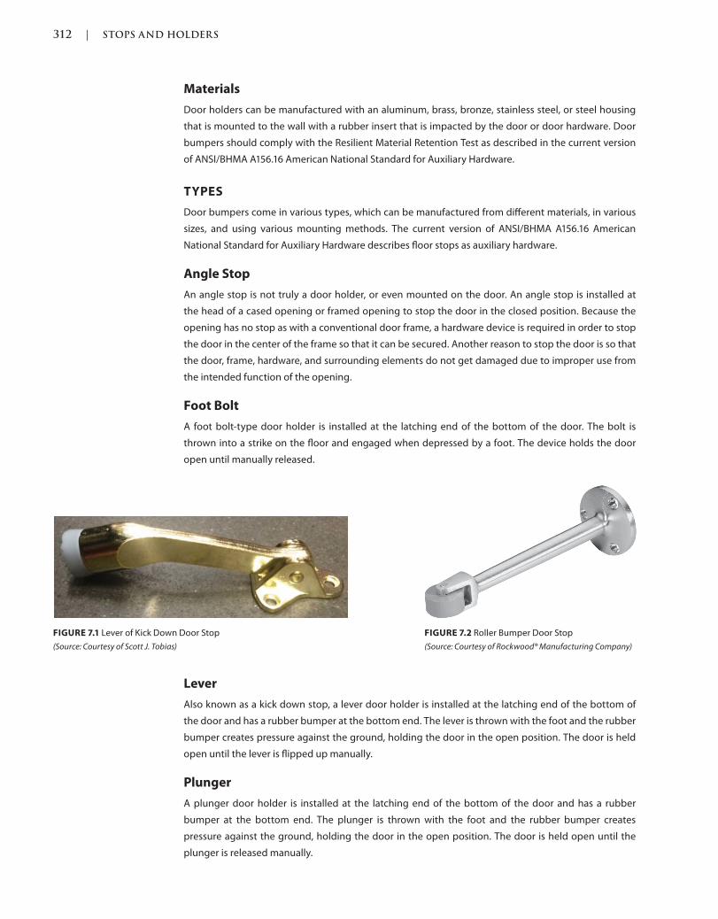
312 | STOPS AND HOLDERS
Trim: 215 x 276 mm c07.indd 03/03/2015 04:34:56:PM Page 312
Materials
Door holders can be manufactured with an aluminum, brass, bronze, stainless steel, or steel housing
that is mounted to the wall with a rubber insert that is impacted by the door or door hardware. Door
bumpers should comply with the Resilient Material Retention Test as described in the current version
of ANSI/BHMA A156.16 American National Standard for Auxiliary Hardware.
TYPES
Door bumpers come in various types, which can be manufactured from different materials, in various
sizes, and using various mounting methods. The current version of ANSI/BHMA A156.16 American
National Standard for Auxiliary Hardware describes floor stops as auxiliary hardware.
Angle Stop
An angle stop is not truly a door holder, or even mounted on the door. An angle stop is installed at
the head of a cased opening or framed opening to stop the door in the closed position. Because the
opening has no stop as with a conventional door frame, a hardware device is required in order to stop
the door in the center of the frame so that it can be secured. Another reason to stop the door is so that
the door, frame, hardware, and surrounding elements do not get damaged due to improper use from
the intended function of the opening.
Foot Bolt
A foot bolt-type door holder is installed at the latching end of the bottom of the door. The bolt is
thrown into a strike on the floor and engaged when depressed by a foot. The device holds the door
open until manually released.
FIGURE 7.1 Lever of Kick Down Door Stop
(Source: Courtesy of Scott J. Tobias)
FIGURE 7.2 Roller Bumper Door Stop
(Source: Courtesy of Rockwood® Manufacturing Company)
Lever
Also known as a kick down stop, a lever door holder is installed at the latching end of the bottom of
the door and has a rubber bumper at the bottom end. The lever is thrown with the foot and the rubber
bumper creates pressure against the ground, holding the door in the open position. The door is held
open until the lever is flipped up manually.
Plunger
A plunger door holder is installed at the latching end of the bottom of the door and has a rubber
bumper at the bottom end. The plunger is thrown with the foot and the rubber bumper creates
pressure against the ground, holding the door in the open position. The door is held open until the
plunger is released manually.
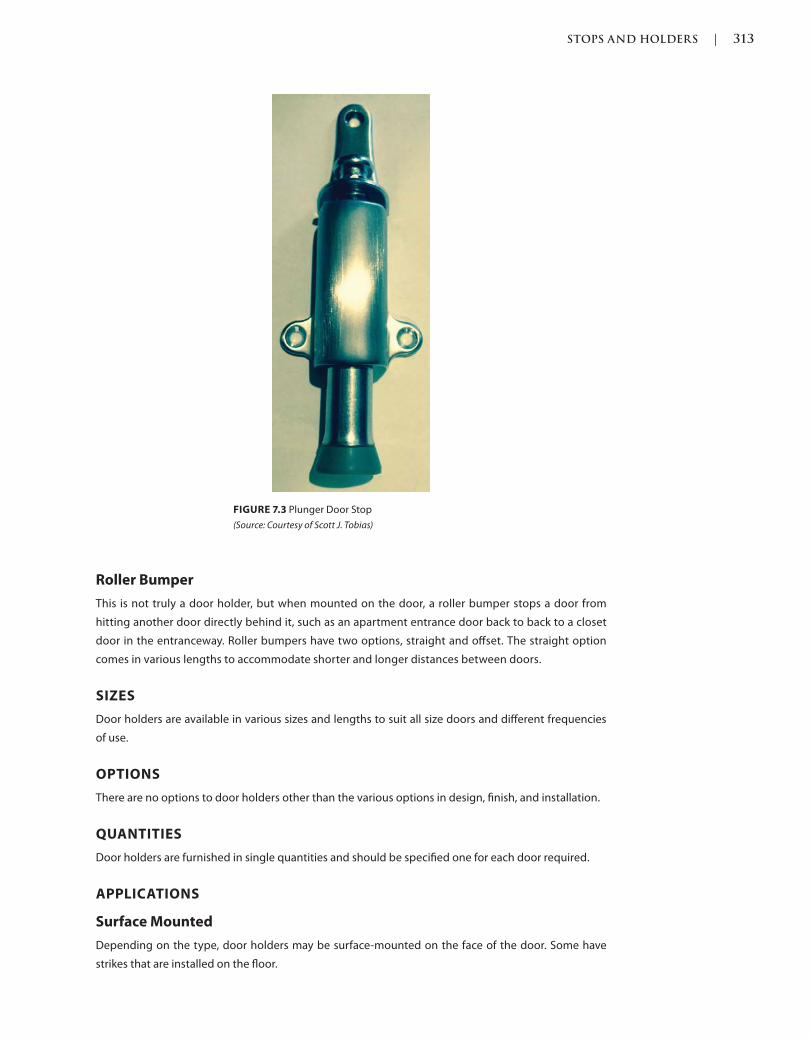
STOPS AND HOLDERS | 313
c07.indd 03/03/2015 04:34:56:PM Page 313Trim: 215 x 276 mm
Roller Bumper
This is not truly a door holder, but when mounted on the door, a roller bumper stops a door from
hitting another door directly behind it, such as an apartment entrance door back to back to a closet
door in the entranceway. Roller bumpers have two options, straight and offset. The straight option
comes in various lengths to accommodate shorter and longer distances between doors.
SIZES
Door holders are available in various sizes and lengths to suit all size doors and different frequencies
of use.
OPTIONS
There are no options to door holders other than the various options in design, finish, and installation.
QUANTITIES
Door holders are furnished in single quantities and should be specified one for each door required.
APPLICATIONS
Surface Mounted
Depending on the type, door holders may be surface-mounted on the face of the door. Some have
strikes that are installed on the floor.
FIGURE 7.3 Plunger Door Stop
(Source: Courtesy of Scott J. Tobias)
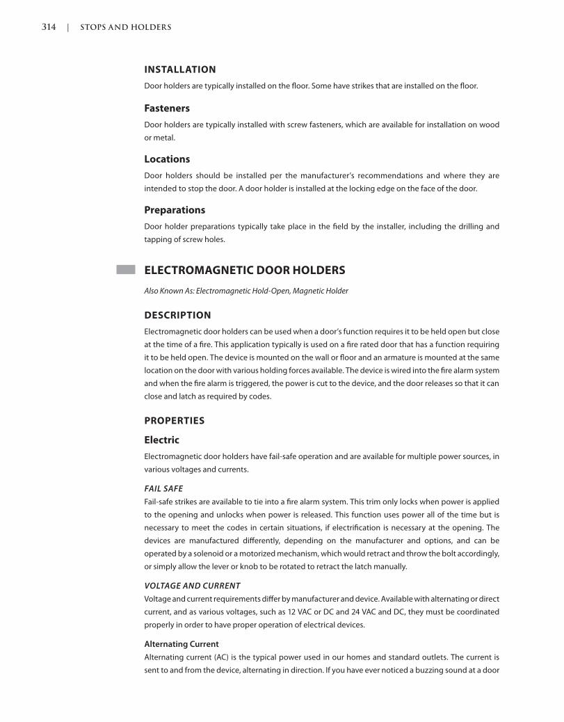
314 | STOPS AND HOLDERS
Trim: 215 x 276 mm c07.indd 03/03/2015 04:34:56:PM Page 314
INSTALLATION
Door holders are typically installed on the floor. Some have strikes that are installed on the floor.
Fasteners
Door holders are typically installed with screw fasteners, which are available for installation on wood
or metal.
Locations
Door holders should be installed per the manufacturer’s recommendations and where they are
intended to stop the door. A door holder is installed at the locking edge on the face of the door.
Preparations
Door holder preparations typically take place in the field by the installer, including the drilling and
tapping of screw holes.
ELECTROMAGNETIC DOOR HOLDERS
Also Known As: Electromagnetic Hold-Open, Magnetic Holder
DESCRIPTION
Electromagnetic door holders can be used when a door’s function requires it to be held open but close
at the time of a fire. This application typically is used on a fire rated door that has a function requiring
it to be held open. The device is mounted on the wall or floor and an armature is mounted at the same
location on the door with various holding forces available. The device is wired into the fire alarm system
and when the fire alarm is triggered, the power is cut to the device, and the door releases so that it can
close and latch as required by codes.
PROPERTIES
Electric
Electromagnetic door holders have fail-safe operation and are available for multiple power sources, in
various voltages and currents.
FAIL SAFE
Fail-safe strikes are available to tie into a fire alarm system. This trim only locks when power is applied
to the opening and unlocks when power is released. This function uses power all of the time but is
necessary to meet the codes in certain situations, if electrification is necessary at the opening. The
devices are manufactured differently, depending on the manufacturer and options, and can be
operated by a solenoid or a motorized mechanism, which would retract and throw the bolt accordingly,
or simply allow the lever or knob to be rotated to retract the latch manually.
VOLTAGE AND CURRENT
Voltage and current requirements differ by manufacturer and device. Available with alternating or direct
current, and as various voltages, such as 12 VAC or DC and 24 VAC and DC, they must be coordinated
properly in order to have proper operation of electrical devices.
Alternating Current
Alternating current (AC) is the typical power used in our homes and standard outlets. The current is
sent to and from the device, alternating in direction. If you have ever noticed a buzzing sound at a door
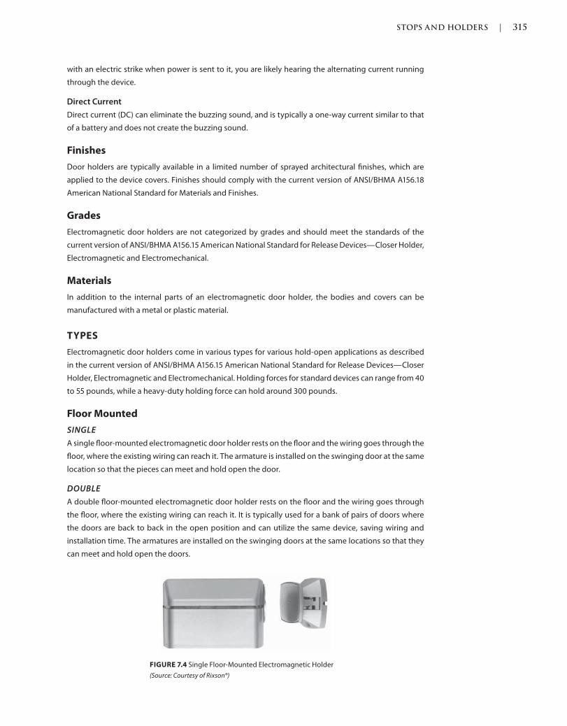
STOPS AND HOLDERS | 315
c07.indd 03/03/2015 04:34:56:PM Page 315Trim: 215 x 276 mm
with an electric strike when power is sent to it, you are likely hearing the alternating current running
through the device.
Direct Current
Direct current (DC) can eliminate the buzzing sound, and is typically a one-way current similar to that
of a battery and does not create the buzzing sound.
Finishes
Door holders are typically available in a limited number of sprayed architectural finishes, which are
applied to the device covers. Finishes should comply with the current version of ANSI/BHMA A156.18
American National Standard for Materials and Finishes.
Grades
Electromagnetic door holders are not categorized by grades and should meet the standards of the
current version of ANSI/BHMA A156.15 American National Standard for Release Devices—Closer Holder,
Electromagnetic and Electromechanical.
Materials
In addition to the internal parts of an electromagnetic door holder, the bodies and covers can be
manufactured with a metal or plastic material.
TYPES
Electromagnetic door holders come in various types for various hold-open applications as described
in the current version of ANSI/BHMA A156.15 American National Standard for Release Devices—Closer
Holder, Electromagnetic and Electromechanical. Holding forces for standard devices can range from 40
to 55 pounds, while a heavy-duty holding force can hold around 300 pounds.
Floor Mounted
SINGLE
A single floor-mounted electromagnetic door holder rests on the floor and the wiring goes through the
floor, where the existing wiring can reach it. The armature is installed on the swinging door at the same
location so that the pieces can meet and hold open the door.
DOUBLE
A double floor-mounted electromagnetic door holder rests on the floor and the wiring goes through
the floor, where the existing wiring can reach it. It is typically used for a bank of pairs of doors where
the doors are back to back in the open position and can utilize the same device, saving wiring and
installation time. The armatures are installed on the swinging doors at the same locations so that they
can meet and hold open the doors.
FIGURE 7.4 Single Floor-Mounted Electromagnetic Holder
(Source: Courtesy of Rixson®)
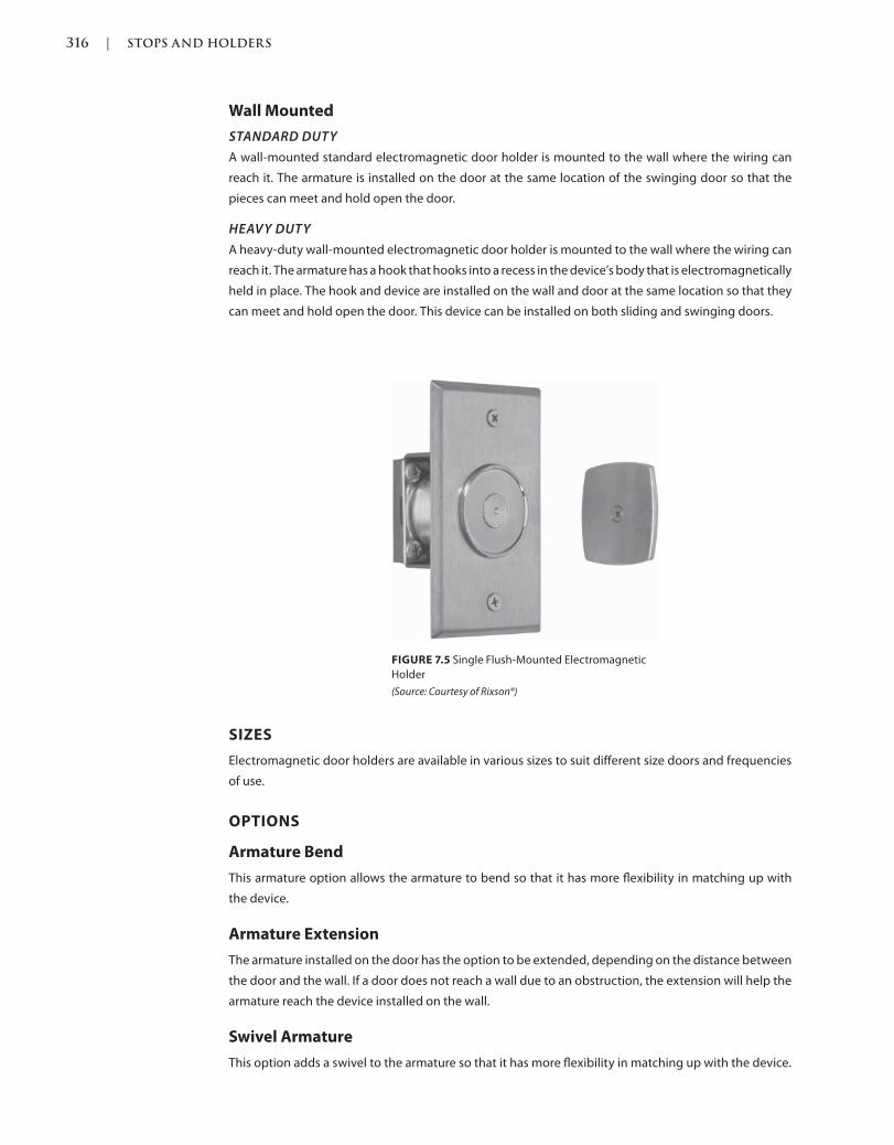
316 | STOPS AND HOLDERS
Trim: 215 x 276 mm c07.indd 03/03/2015 04:34:56:PM Page 316
SIZES
Electromagnetic door holders are available in various sizes to suit different size doors and frequencies
of use.
OPTIONS
Armature Bend
This armature option allows the armature to bend so that it has more flexibility in matching up with
the device.
Armature Extension
The armature installed on the door has the option to be extended, depending on the distance between
the door and the wall. If a door does not reach a wall due to an obstruction, the extension will help the
armature reach the device installed on the wall.
Swivel Armature
This option adds a swivel to the armature so that it has more flexibility in matching up with the device.
Wall Mounted
STANDARD DUTY
A wall-mounted standard electromagnetic door holder is mounted to the wall where the wiring can
reach it. The armature is installed on the door at the same location of the swinging door so that the
pieces can meet and hold open the door.
HEAVY DUTY
A heavy-duty wall-mounted electromagnetic door holder is mounted to the wall where the wiring can
reach it. The armature has a hook that hooks into a recess in the device’s body that is electromagnetically
held in place. The hook and device are installed on the wall and door at the same location so that they
can meet and hold open the door. This device can be installed on both sliding and swinging doors.
FIGURE 7.5 Single Flush-Mounted Electromagnetic
Holder
(Source: Courtesy of Rixson®)
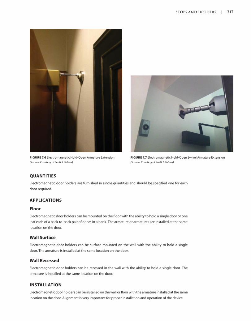
STOPS AND HOLDERS | 317
c07.indd 03/03/2015 04:34:56:PM Page 317Trim: 215 x 276 mm
QUANTITIES
Electromagnetic door holders are furnished in single quantities and should be specified one for each
door required.
APPLICATIONS
Floor
Electromagnetic door holders can be mounted on the floor with the ability to hold a single door or one
leaf each of a back-to-back pair of doors in a bank. The armature or armatures are installed at the same
location on the door.
Wall Surface
Electromagnetic door holders can be surface-mounted on the wall with the ability to hold a single
door. The armature is installed at the same location on the door.
Wall Recessed
Electromagnetic door holders can be recessed in the wall with the ability to hold a single door. The
armature is installed at the same location on the door.
INSTALLATION
Electromagnetic door holders can be installed on the wall or floor with the armature installed at the same
location on the door. Alignment is very important for proper installation and operation of the device.
FIGURE 7.7 Electromagnetic Hold-Open Swivel Armature Extension
(Source: Courtesy of Scott J. Tobias)
FIGURE 7.6 Electromagnetic Hold-Open Armature Extension
(Source: Courtesy of Scott J. Tobias)
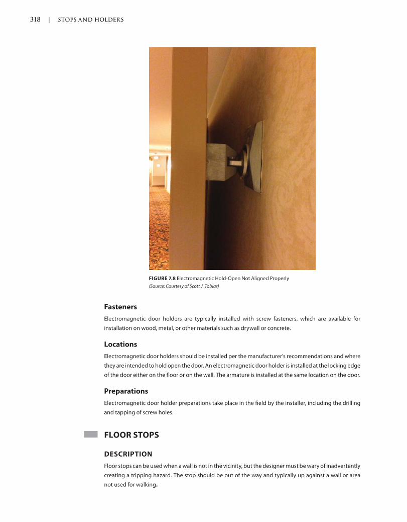
318 | STOPS AND HOLDERS
Trim: 215 x 276 mm c07.indd 03/03/2015 04:34:56:PM Page 318
Fasteners
Electromagnetic door holders are typically installed with screw fasteners, which are available for
installation on wood, metal, or other materials such as drywall or concrete.
Locations
Electromagnetic door holders should be installed per the manufacturer’s recommendations and where
they are intended to hold open the door. An electromagnetic door holder is installed at the locking edge
of the door either on the floor or on the wall. The armature is installed at the same location on the door.
Preparations
Electromagnetic door holder preparations take place in the field by the installer, including the drilling
and tapping of screw holes.
FLOOR STOPS
DESCRIPTION
Floor stops can be used when a wall is not in the vicinity, but the designer must be wary of inadvertently
creating a tripping hazard. The stop should be out of the way and typically up against a wall or area
not used for walking.
FIGURE 7.8 Electromagnetic Hold-Open Not Aligned Properly
(Source: Courtesy of Scott J. Tobias)
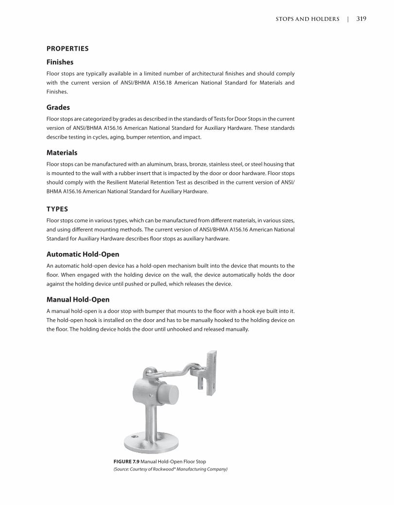
STOPS AND HOLDERS | 319
c07.indd 03/03/2015 04:34:56:PM Page 319Trim: 215 x 276 mm
PROPERTIES
Finishes
Floor stops are typically available in a limited number of architectural finishes and should comply
with the current version of ANSI/BHMA A156.18 American National Standard for Materials and
Finishes.
Grades
Floor stops are categorized by grades as described in the standards of Tests for Door Stops in the current
version of ANSI/BHMA A156.16 American National Standard for Auxiliary Hardware. These standards
describe testing in cycles, aging, bumper retention, and impact.
Materials
Floor stops can be manufactured with an aluminum, brass, bronze, stainless steel, or steel housing that
is mounted to the wall with a rubber insert that is impacted by the door or door hardware. Floor stops
should comply with the Resilient Material Retention Test as described in the current version of ANSI/
BHMA A156.16 American National Standard for Auxiliary Hardware.
TYPES
Floor stops come in various types, which can be manufactured from different materials, in various sizes,
and using different mounting methods. The current version of ANSI/BHMA A156.16 American National
Standard for Auxiliary Hardware describes floor stops as auxiliary hardware.
Automatic Hold-Open
An automatic hold-open device has a hold-open mechanism built into the device that mounts to the
floor. When engaged with the holding device on the wall, the device automatically holds the door
against the holding device until pushed or pulled, which releases the device.
Manual Hold-Open
A manual hold-open is a door stop with bumper that mounts to the floor with a hook eye built into it.
The hold-open hook is installed on the door and has to be manually hooked to the holding device on
the floor. The holding device holds the door until unhooked and released manually.
FIGURE 7.9 Manual Hold-Open Floor Stop
(Source: Courtesy of Rockwood® Manufacturing Company)
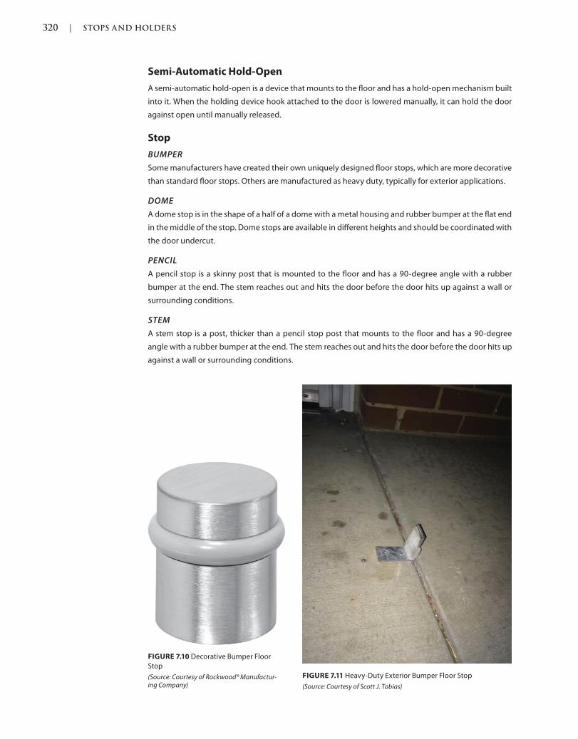
320 | STOPS AND HOLDERS
Trim: 215 x 276 mm c07.indd 03/03/2015 04:34:56:PM Page 320
Semi-Automatic Hold-Open
A semi-automatic hold-open is a device that mounts to the floor and has a hold-open mechanism built
into it. When the holding device hook attached to the door is lowered manually, it can hold the door
against open until manually released.
Stop
BUMPER
Some manufacturers have created their own uniquely designed floor stops, which are more decorative
than standard floor stops. Others are manufactured as heavy duty, typically for exterior applications.
DOME
A dome stop is in the shape of a half of a dome with a metal housing and rubber bumper at the flat end
in the middle of the stop. Dome stops are available in different heights and should be coordinated with
the door undercut.
PENCIL
A pencil stop is a skinny post that is mounted to the floor and has a 90-degree angle with a rubber
bumper at the end. The stem reaches out and hits the door before the door hits up against a wall or
surrounding conditions.
STEM
A stem stop is a post, thicker than a pencil stop post that mounts to the floor and has a 90-degree
angle with a rubber bumper at the end. The stem reaches out and hits the door before the door hits up
against a wall or surrounding conditions.
FIGURE 7.10 Decorative Bumper Floor
Stop
(Source: Courtesy of Rockwood® Manufactur-ing Company)
FIGURE 7.11 Heavy-Duty Exterior Bumper Floor Stop
(Source: Courtesy of Scott J. Tobias)
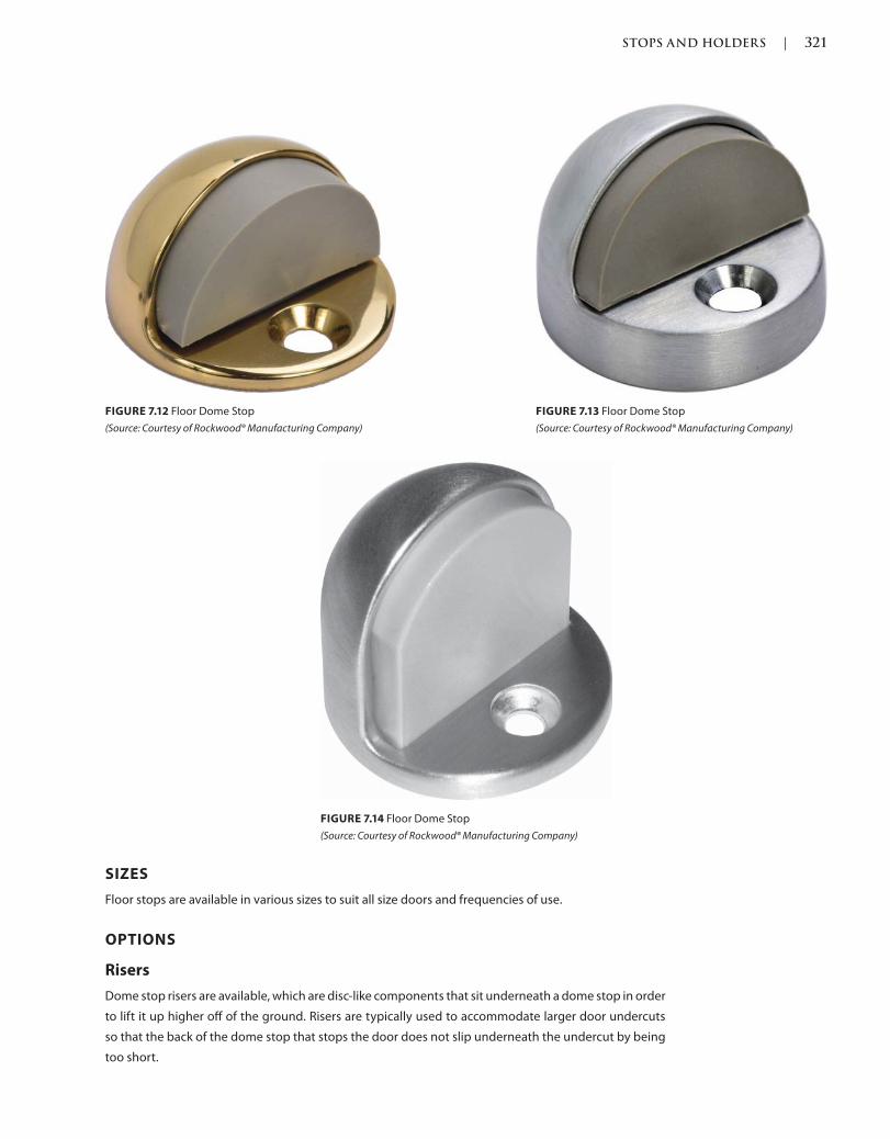
STOPS AND HOLDERS | 321
c07.indd 03/03/2015 04:34:56:PM Page 321Trim: 215 x 276 mm
SIZES
Floor stops are available in various sizes to suit all size doors and frequencies of use.
OPTIONS
Risers
Dome stop risers are available, which are disc-like components that sit underneath a dome stop in order
to lift it up higher off of the ground. Risers are typically used to accommodate larger door undercuts
so that the back of the dome stop that stops the door does not slip underneath the undercut by being
too short.
FIGURE 7.12 Floor Dome Stop
(Source: Courtesy of Rockwood® Manufacturing Company)
FIGURE 7.13 Floor Dome Stop
(Source: Courtesy of Rockwood® Manufacturing Company)
FIGURE 7.14 Floor Dome Stop
(Source: Courtesy of Rockwood® Manufacturing Company)
322 | STOPS AND HOLDERS
Trim: 215 x 276 mm c07.indd 03/03/2015 04:34:56:PM Page 322
QUANTITIES
Wall stops are furnished in single quantities and should be specified one for each door required.
APPLICATIONS
Surface Mounted
Depending on the type, floor stops are surface-mounted on the floor, face of the door, or both.
INSTALLATION
Depending on the type, floor stops are typically installed on the floor, face of the door, or both. Floor
stops would be the second most preferred stopping method to a wall stop. Floor stops might contribute
to a tripping hazard if not installed on the floor in the proper location or with the optimal application.
Cleaning a wall stop is also easier than an overhead or floor stop, especially in sanitary environments
such as a hospital.
Fasteners
Floor stops are typically installed with screw fasteners, which are available for installation on wood,
metal, or other materials such as drywall or concrete.
Locations
Floor stops should be installed per the manufacturer’s recommendations and where it is intended to
stop the door. A floor stop would be installed at the locking edge of the door as close to the wall as
possible to avoid a tripping hazard. The stop would be placed so that the paddle arm, push pull, exit
device trim, lockset lever handle, or any other operating device would be protected by the door hitting
the stop before any other operating hardware.
Preparations
Floor stop preparations take place in the field by the installer, including the drilling and tapping of
screw holes.
WALL STOPS
DESCRIPTION
Wall stops should be the first choice, especially in healthcare facilities, as the bacteria and dirt
are much easier to clean at a standing height surface than on the floor or overhead. They can be
cleaned within arm’s length—they can easily be sprayed with a cleaning agent and wiped clean
without having to bend down or use a mop, which can create a buildup of dirt and bacteria over
time.
PROPERTIES
Finishes
Wall stops are typically available in a limited number of architectural finishes and should comply
with the current version of ANSI/BHMA A156.18 American National Standard for Materials and
Finishes.
STOPS AND HOLDERS | 323
c07.indd 03/03/2015 04:34:56:PM Page 323Trim: 215 x 276 mm
Grades
Wall stops are categorized by grades as described in the standards of Tests for Door Stops in the current
version of ANSI/BHMA A156.16 American National Standard for Auxiliary Hardware. These standards
describe testing in cycles, aging, bumper retention, and impact.
Materials
Wall stops can be manufactured with an aluminum, brass, bronze, stainless steel, or steel housing that
gets mounted to the wall with a rubber insert that is impacted by the door or door hardware. Wall stops
should comply with the Resilient Material Retention Test as described in the current version of ANSI/
BHMA A156.16 American National Standard for Auxiliary Hardware.
TYPES
Wall stops have various types, which can be manufactured from different materials, in various sizes,
and using different mounting methods. The current version of ANSI/BHMA A156.16 American National
Standard for Auxiliary Hardware describes wall stops as auxiliary hardware.
Automatic Hold-Open
An automatic hold-open device has a hold-open mechanism built into the device that protrudes off
the face of the door. When engaged with the holding device on the wall, the hold-open mechanism
automatically holds the door against the holding device until it is pushed or pulled, which releases the
device.
Manual Hold-Open
A manual hold-open is a door stop with bumper that protrudes off of the face of the door with a hook
eye built into it. The hold-open hook is installed on the wall and has to be manually hooked to the
holding device on the wall. The holding device holds the door until unhooked and released manually.
Semi-Automatic Hold-Open
A semi-automatic hold-open is a device that protrudes off of the face of the door that has a hold-open
mechanism built into it. When the holding device hook attached to the wall is lowered manually, it can
hold the door open until it is manually released.
Stop
BUMPER
Concave
Concave wall bumpers can be manufactured with or without a metal housing and with or without
visible screws. Regardless of the housing, there is a rubber bumper that is just a rim with a hollowed-
out center. This configuration is typically specified when installing with a bored or cylindrical
locket that has a pushbutton feature on the inside lever. Without a hollowed-out center, every time
the lever with the pushbutton hits the stop, the pushbutton would depress and lock the lockset
unintentionally.
Convex
Convex wall bumpers can be manufactured with or without a metal housing and with or without
visible screws. Regardless of the housing, there is a solid rubber bumper. This configuration is typically
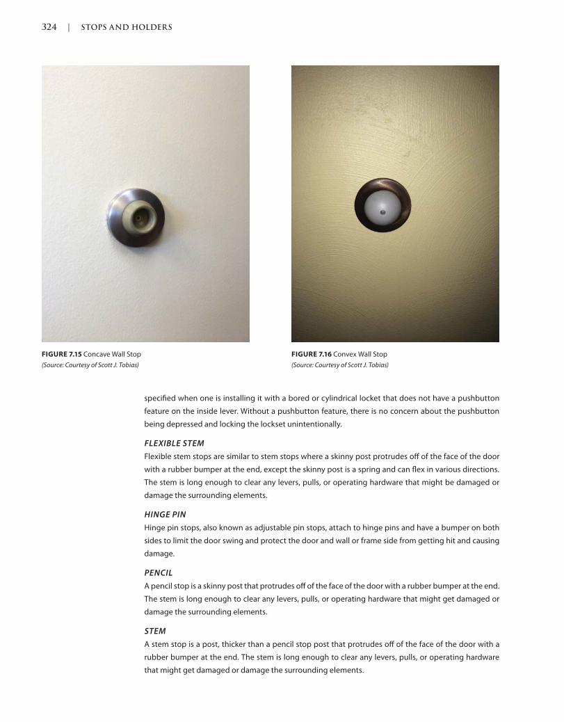
324 | STOPS AND HOLDERS
Trim: 215 x 276 mm c07.indd 03/03/2015 04:34:56:PM Page 324
specified when one is installing it with a bored or cylindrical locket that does not have a pushbutton
feature on the inside lever. Without a pushbutton feature, there is no concern about the pushbutton
being depressed and locking the lockset unintentionally.
FLEXIBLE STEM
Flexible stem stops are similar to stem stops where a skinny post protrudes off of the face of the door
with a rubber bumper at the end, except the skinny post is a spring and can flex in various directions.
The stem is long enough to clear any levers, pulls, or operating hardware that might be damaged or
damage the surrounding elements.
HINGE PIN
Hinge pin stops, also known as adjustable pin stops, attach to hinge pins and have a bumper on both
sides to limit the door swing and protect the door and wall or frame side from getting hit and causing
damage.
PENCIL
A pencil stop is a skinny post that protrudes off of the face of the door with a rubber bumper at the end.
The stem is long enough to clear any levers, pulls, or operating hardware that might get damaged or
damage the surrounding elements.
STEM
A stem stop is a post, thicker than a pencil stop post that protrudes off of the face of the door with a
rubber bumper at the end. The stem is long enough to clear any levers, pulls, or operating hardware
that might get damaged or damage the surrounding elements.
FIGURE 7.15 Concave Wall Stop
(Source: Courtesy of Scott J. Tobias)
FIGURE 7.16 Convex Wall Stop
(Source: Courtesy of Scott J. Tobias)
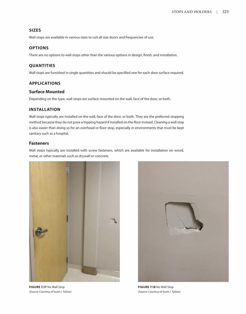
STOPS AND HOLDERS | 325
c07.indd 03/03/2015 04:35:52:PM Page 325Trim: 215 x 276 mm
SIZES
Wall stops are available in various sizes to suit all size doors and frequencies of use.
OPTIONS
There are no options to wall stops other than the various options in design, finish, and installation.
QUANTITIES
Wall stops are furnished in single quantities and should be specified one for each door surface required.
APPLICATIONS
Surface Mounted
Depending on the type, wall stops are surface-mounted on the wall, face of the door, or both.
INSTALLATION
Wall stops typically are installed on the wall, face of the door, or both. They are the preferred stopping
method because they do not pose a tripping hazard if installed on the floor instead. Cleaning a wall stop
is also easier than doing so for an overhead or floor stop, especially in environments that must be kept
sanitary such as a hospital.
Fasteners
Wall stops typically are installed with screw fasteners, which are available for installation on wood,
metal, or other materials such as drywall or concrete.
FIGURE 7.17 No Wall Stop
(Source: Courtesy of Scott J. Tobias)
FIGURE 7.18 No Wall Stop
(Source: Courtesy of Scott J. Tobias)
326 | STOPS AND HOLDERS
Trim: 215 x 276 mm c07.indd 03/03/2015 04:35:52:PM Page 326
Locations
Wall stops should be installed at the height given in the manufacturer’s recommendations and where
they are intended to stop the door. A wall bumper would be installed at the centerline of the hospital
arm, push pull, exit device trim, lockset lever handle, or any other operating device. A wall stem stop
would be installed toward the bottom end of the door, sticking out far enough to reach the wall
before any of the operating hardware to avoid damage to the door surface or surrounding elements.
Preparations
Wall stop preparations take place in the field by the installer, including the drilling and tapping of screw
holes.
REFERENCES
Codes and standards are available to set the minimum requirements of door openings (see the
Introduction of this book for more information). Some jurisdictions have specific codes and standards,
which were either modified from another existing code or created for their own use.
Language and section numbers can change slightly or drastically when the codes are updated. Look for
an outline, if available, of the changes that took place in the respective update.
CODES
International Building Code (IBC)
The following are chapters of a modified or fully adopted version of the International Building Code
that refer to stops and holders or door hardware in general:
Chapter 7: Fire and Smoke Protection Features
Chapter 10: Means of Egress
Chapter 17: Special Inspections and Tests
National Fire Protection Association (NFPA) 101: Life Safety Code
The following is a chapter of a modified or fully adopted version of the NFPA 101: Life Safety Code that
refers to stops and holders or door hardware in general:
Chapter 7
STANDARDS
ADA Accessibility Guidelines for Buildings and Facilities (ADAAG)
The following is a chapter of a modified or fully adopted version of the ADA Accessibility Guidelines for
Buildings and Facilities that refers to stops and holders or door hardware in general:
Chapter 4: Accessible Routes
ASTM International (ASTM)
There are hundreds of ASTM International testing standards that are related to doors and door
hardware, from material and assembly testing to installation and application testing.
STOPS AND HOLDERS | 327
c07.indd 03/03/2015 04:35:52:PM Page 327Trim: 215 x 276 mm
Door and Hardware Institute (DHI)
The following are technical documents available for reference that refer to stops and holders or door
hardware in general:
Abbreviations and Symbols
Basic Architectural Hardware
Hardware for Healthcare Facilities
Installation Guide for Doors and Hardware
Processing Hardware for Custom Aluminum Entrances
Recommended Locations for Builders Hardware Custom Steel Doors & Frames
Recommended Locations for Architectural Hardware for Standard Steel Doors
& Frames
Recommended Locations for Architectural Hardware for Flush Wood Doors
Recommended Procedures for Processing Hardware Schedules and Templates
Sequence and Format for the Hardware Schedule
Tech-Talk ASD-1 Aluminum Storefront Doors
International Code Council A117.1 Accessible and Usable Buildings
and Facilities (ICC)
The following is a chapter of a modified or fully adopted version of the ICC A117.1 Accessible and Usable
Buildings and Facilities that refers to stops and holders or door hardware in general:
Chapter 4 Accessible Routes
National Fire Protection Association (NFPA)
The following are chapters of a modified or fully adopted version of NFPA 80: Standard for Fire Doors
and Other Opening Protectives that refer to stops and holders or door hardware in general:
Chapter 5: Care and Maintenance
Chapter 6: Swinging Doors with Builders Hardware
Chapter 7: Swinging Doors with Fire Door Hardware
Chapter 8: Horizontally Sliding Doors
Chapter 9: Special-Purpose Horizontally Sliding Accordion or Folding Doors
Chapter 16: Access Doors
Chapter 19: Installation, Testing, and Maintenance of Fire Dampers
Annex A: Explanatory Material
The following is a chapter of a modified or fully adopted version of NFPA 105: Standard for Smoke
Door Assemblies and Other Opening Protectives that refers to stops and holders or door hardware
in general:
Chapter 6: Installation, Testing, and Maintenance of Smoke Dampers
The following is a chapter of a modified or fully adopted version of NFPA 252: Standard Method of Fire
Tests of Door Assemblies that refers to stops and holders or door hardware in general:
Chapter 5: Fire Door Assembly
Annex B: Commentary
328 | STOPS AND HOLDERS
Trim: 215 x 276 mm c07.indd 03/03/2015 04:35:52:PM Page 328
American National Standards Institute/Builders Hardware Manufacturers
Association (ANSI/BHMA)
The following are standards that refer to stops and holders or door hardware in general:
ANSI/BHMA A156.6 American National Standard for Architectural Door Trim
ANSI/BHMA A156.15 American National Standard for Release Devices Closer Holder, Electromag-
netic and Electromechanical
ANSI/BHMA A156.16 American National Standard for Auxiliary Hardware
ANSI/BHMA A156.18 American National Standard for Materials and Finishes
329
c08.indd Page 329 03/03/2015 05:6:30:PM
Next in the sequence we list accessories that include astragals, thresholds, weatherstripping, and gas-
keting. We use these hardware types to seal the clearances around the perimeter of an opening. This
can help with a number of issues including keeping sound, light, and smoke either in or out, maintain-
ing energy efficiency, and helping to contain the inside weather and conditions inside the structure and
the outside weather and conditions outside. Although most weatherstripping and gaskets are surface
mounted or recessed installed, some door frame manufacturers offer their frames with gaskets already
installed in kerfs where the rabbet meets the stop of the frame.
ASTRAGALS
Also Known As: Meeting Stile Seals, Gaskets, Weatherstripping
DESCRIPTION
An astragal is installed to cover or fill the clearance in between a pair of doors. Astragals are available
in different configurations and are installed on the surface, recessed, or wrapped around the edge of
a door in one piece or two. Astragals are recommended to be installed the entire height of a door and
might be required by certain codes.
PROPERTIES
Finishes
Astragals are typically available in a limited number of architectural finishes and should comply with
ANSI/BHMA A156.18 American National Standard for Materials and Finishes, 2012. Although some
manufacturers might offer other options, the most typical astragal finishes available are anodized alu-
minum, bronze, dark bronze gold, and painted finishes. Astragals with gasket materials are typically
available in brown, black, gray, tan, and white and can be manufactured from foam, neoprene, santo-
prene, silicone, brush, and other materials.
Accessories
8
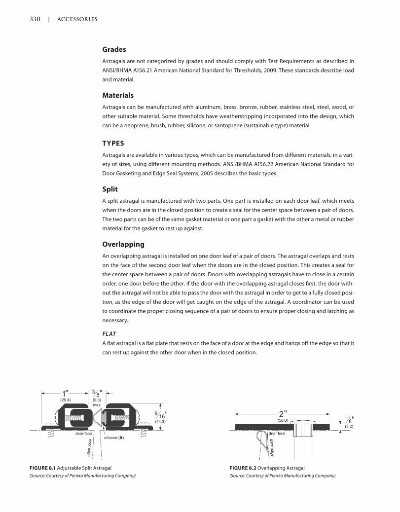
330 | ACCESSORIES
c08.indd Page 330 03/03/2015 05:6:30:PM
Grades
Astragals are not categorized by grades and should comply with Test Requirements as described in
ANSI/BHMA A156.21 American National Standard for Thresholds, 2009. These standards describe load
and material.
Materials
Astragals can be manufactured with aluminum, brass, bronze, rubber, stainless steel, steel, wood, or
other suitable material. Some thresholds have weatherstripping incorporated into the design, which
can be a neoprene, brush, rubber, silicone, or santoprene (sustainable type) material.
TYPES
Astragals are available in various types, which can be manufactured from different materials, in a vari-
ety of sizes, using different mounting methods. ANSI/BHMA A156.22 American National Standard for
Door Gasketing and Edge Seal Systems, 2005 describes the basic types.
Split
A split astragal is manufactured with two parts. One part is installed on each door leaf, which meets
when the doors are in the closed position to create a seal for the center space between a pair of doors.
The two parts can be of the same gasket material or one part a gasket with the other a metal or rubber
material for the gasket to rest up against.
Overlapping
An overlapping astragal is installed on one door leaf of a pair of doors. The astragal overlaps and rests
on the face of the second door leaf when the doors are in the closed position. This creates a seal for
the center space between a pair of doors. Doors with overlapping astragals have to close in a certain
order, one door before the other. If the door with the overlapping astragal closes first, the door with-
out the astragal will not be able to pass the door with the astragal in order to get to a fully closed posi-
tion, as the edge of the door will get caught on the edge of the astragal. A coordinator can be used
to coordinate the proper closing sequence of a pair of doors to ensure proper closing and latching as
necessary.
FLAT
A flat astragal is a flat plate that rests on the face of a door at the edge and hangs off the edge so that it
can rest up against the other door when in the closed position.
FIGURE 8.1 Adjustable Split Astragal
(Source: Courtesy of Pemko Manufacturing Company)
FIGURE 8.2 Overlapping Astragal
(Source: Courtesy of Pemko Manufacturing Company)
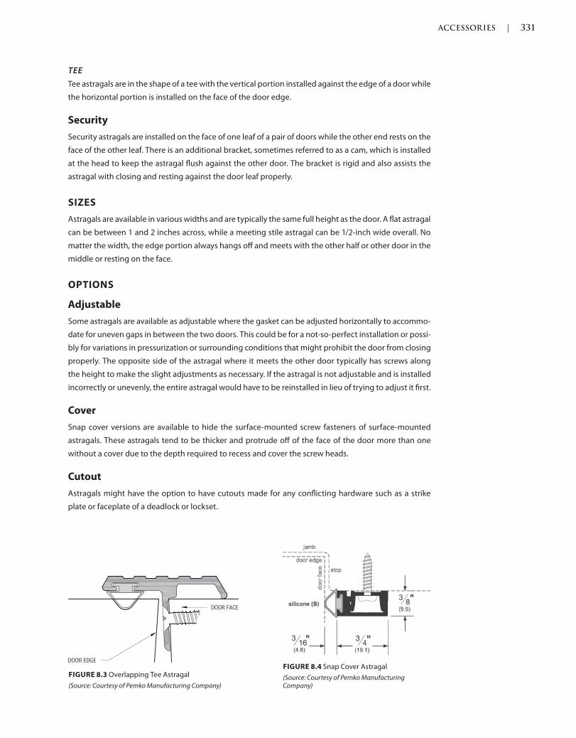
ACCESSORIES | 331
c08.indd Page 331 03/03/2015 05:6:30:PM
TEE
Tee astragals are in the shape of a tee with the vertical portion installed against the edge of a door while
the horizontal portion is installed on the face of the door edge.
Security
Security astragals are installed on the face of one leaf of a pair of doors while the other end rests on the
face of the other leaf. There is an additional bracket, sometimes referred to as a cam, which is installed
at the head to keep the astragal flush against the other door. The bracket is rigid and also assists the
astragal with closing and resting against the door leaf properly.
SIZES
Astragals are available in various widths and are typically the same full height as the door. A flat astragal
can be between 1 and 2 inches across, while a meeting stile astragal can be 1/2-inch wide overall. No
matter the width, the edge portion always hangs off and meets with the other half or other door in the
middle or resting on the face.
OPTIONS
Adjustable
Some astragals are available as adjustable where the gasket can be adjusted horizontally to accommo-
date for uneven gaps in between the two doors. This could be for a not-so-perfect installation or possi-
bly for variations in pressurization or surrounding conditions that might prohibit the door from closing
properly. The opposite side of the astragal where it meets the other door typically has screws along
the height to make the slight adjustments as necessary. If the astragal is not adjustable and is installed
incorrectly or unevenly, the entire astragal would have to be reinstalled in lieu of trying to adjust it first.
Cover
Snap cover versions are available to hide the surface-mounted screw fasteners of surface-mounted
astragals. These astragals tend to be thicker and protrude off of the face of the door more than one
without a cover due to the depth required to recess and cover the screw heads.
Cutout
Astragals might have the option to have cutouts made for any conflicting hardware such as a strike
plate or faceplate of a deadlock or lockset.
FIGURE 8.3 Overlapping Tee Astragal
(Source: Courtesy of Pemko Manufacturing Company)
FIGURE 8.4 Snap Cover Astragal
(Source: Courtesy of Pemko Manufacturing Company)
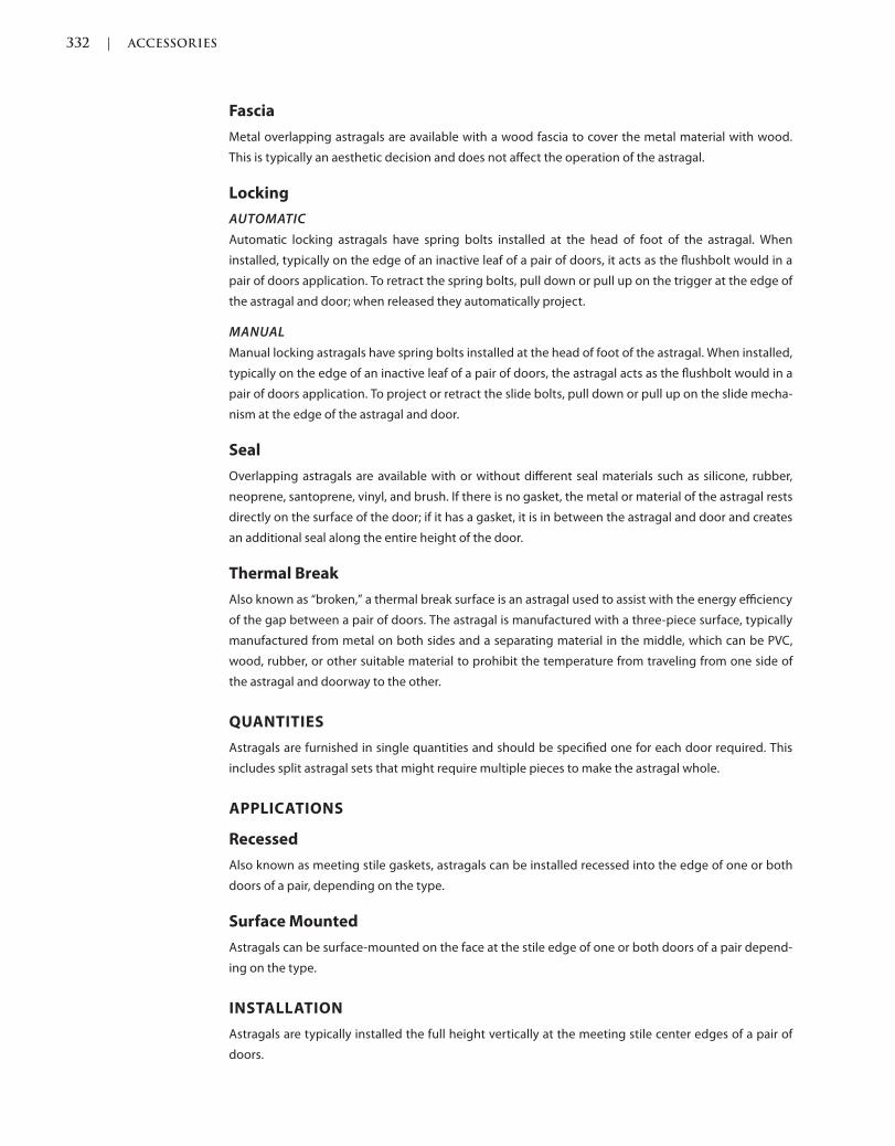
332 | ACCESSORIES
c08.indd Page 332 03/03/2015 05:6:30:PM
Fascia
Metal overlapping astragals are available with a wood fascia to cover the metal material with wood.
This is typically an aesthetic decision and does not affect the operation of the astragal.
Locking
AUTOMATIC
Automatic locking astragals have spring bolts installed at the head of foot of the astragal. When
installed, typically on the edge of an inactive leaf of a pair of doors, it acts as the flushbolt would in a
pair of doors application. To retract the spring bolts, pull down or pull up on the trigger at the edge of
the astragal and door; when released they automatically project.
MANUAL
Manual locking astragals have spring bolts installed at the head of foot of the astragal. When installed,
typically on the edge of an inactive leaf of a pair of doors, the astragal acts as the flushbolt would in a
pair of doors application. To project or retract the slide bolts, pull down or pull up on the slide mecha-
nism at the edge of the astragal and door.
Seal
Overlapping astragals are available with or without different seal materials such as silicone, rubber,
neoprene, santoprene, vinyl, and brush. If there is no gasket, the metal or material of the astragal rests
directly on the surface of the door; if it has a gasket, it is in between the astragal and door and creates
an additional seal along the entire height of the door.
Thermal Break
Also known as “broken,” a thermal break surface is an astragal used to assist with the energy efficiency
of the gap between a pair of doors. The astragal is manufactured with a three-piece surface, typically
manufactured from metal on both sides and a separating material in the middle, which can be PVC,
wood, rubber, or other suitable material to prohibit the temperature from traveling from one side of
the astragal and doorway to the other.
QUANTITIES
Astragals are furnished in single quantities and should be specified one for each door required. This
includes split astragal sets that might require multiple pieces to make the astragal whole.
APPLICATIONS
Recessed
Also known as meeting stile gaskets, astragals can be installed recessed into the edge of one or both
doors of a pair, depending on the type.
Surface Mounted
Astragals can be surface-mounted on the face at the stile edge of one or both doors of a pair depend-
ing on the type.
INSTALLATION
Astragals are typically installed the full height vertically at the meeting stile center edges of a pair of
doors.
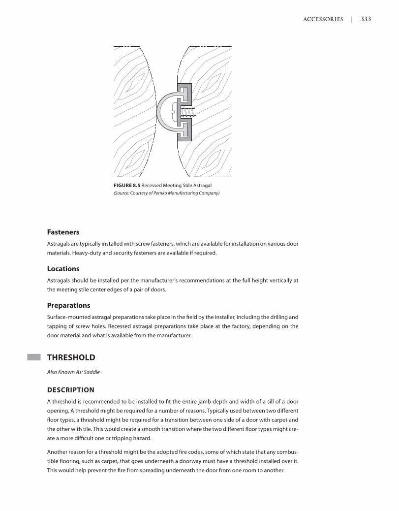
ACCESSORIES | 333
c08.indd Page 333 03/03/2015 05:6:30:PM
Fasteners
Astragals are typically installed with screw fasteners, which are available for installation on various door
materials. Heavy-duty and security fasteners are available if required.
Locations
Astragals should be installed per the manufacturer’s recommendations at the full height vertically at
the meeting stile center edges of a pair of doors.
Preparations
Surface-mounted astragal preparations take place in the field by the installer, including the drilling and
tapping of screw holes. Recessed astragal preparations take place at the factory, depending on the
door material and what is available from the manufacturer.
THRESHOLD
Also Known As: Saddle
DESCRIPTION
A threshold is recommended to be installed to fit the entire jamb depth and width of a sill of a door
opening. A threshold might be required for a number of reasons. Typically used between two different
floor types, a threshold might be required for a transition between one side of a door with carpet and
the other with tile. This would create a smooth transition where the two different floor types might cre-
ate a more difficult one or tripping hazard.
Another reason for a threshold might be the adopted fire codes, some of which state that any combus-
tible flooring, such as carpet, that goes underneath a doorway must have a threshold installed over it.
This would help prevent the fire from spreading underneath the door from one room to another.
FIGURE 8.5 Recessed Meeting Stile Astragal
(Source: Courtesy of Pemko Manufacturing Company)
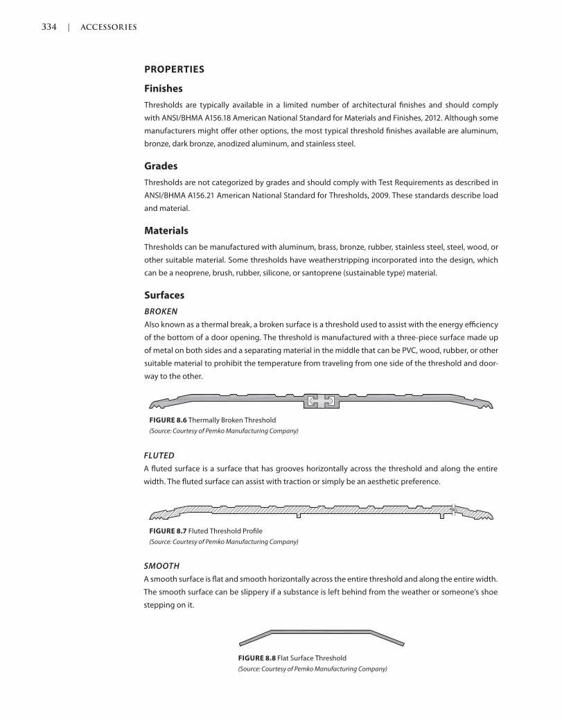
334 | ACCESSORIES
c08.indd Page 334 03/03/2015 05:6:30:PM
PROPERTIES
Finishes
Thresholds are typically available in a limited number of architectural finishes and should comply
with ANSI/BHMA A156.18 American National Standard for Materials and Finishes, 2012. Although some
manufacturers might offer other options, the most typical threshold finishes available are aluminum,
bronze, dark bronze, anodized aluminum, and stainless steel.
Grades
Thresholds are not categorized by grades and should comply with Test Requirements as described in
ANSI/BHMA A156.21 American National Standard for Thresholds, 2009. These standards describe load
and material.
Materials
Thresholds can be manufactured with aluminum, brass, bronze, rubber, stainless steel, steel, wood, or
other suitable material. Some thresholds have weatherstripping incorporated into the design, which
can be a neoprene, brush, rubber, silicone, or santoprene (sustainable type) material.
Surfaces
BROKEN
Also known as a thermal break, a broken surface is a threshold used to assist with the energy efficiency
of the bottom of a door opening. The threshold is manufactured with a three-piece surface made up
of metal on both sides and a separating material in the middle that can be PVC, wood, rubber, or other
suitable material to prohibit the temperature from traveling from one side of the threshold and door-
way to the other.
FIGURE 8.6 Thermally Broken Threshold
(Source: Courtesy of Pemko Manufacturing Company)
FIGURE 8.7 Fluted Threshold Profile
(Source: Courtesy of Pemko Manufacturing Company)
FIGURE 8.8 Flat Surface Threshold
(Source: Courtesy of Pemko Manufacturing Company)
FLUTED
A fluted surface is a surface that has grooves horizontally across the threshold and along the entire
width. The fluted surface can assist with traction or simply be an aesthetic preference.
SMOOTH
A smooth surface is flat and smooth horizontally across the entire threshold and along the entire width.
The smooth surface can be slippery if a substance is left behind from the weather or someone’s shoe
stepping on it.
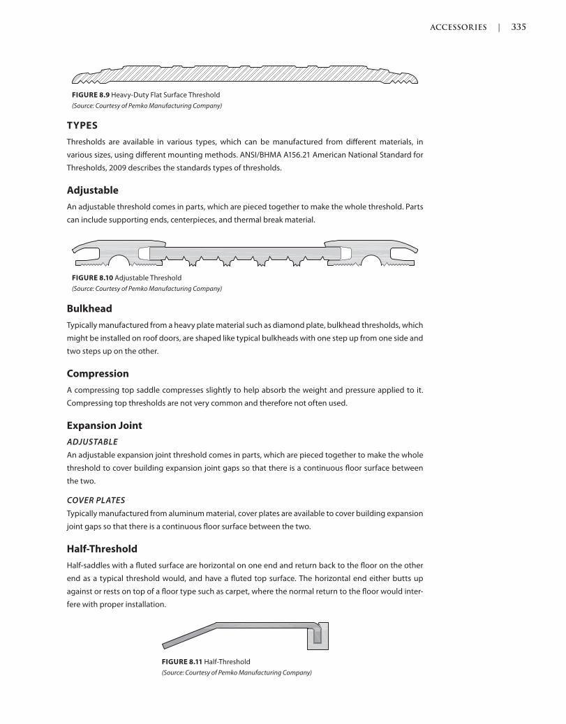
ACCESSORIES | 335
c08.indd Page 335 03/03/2015 05:6:30:PM
TYPES
Thresholds are available in various types, which can be manufactured from different materials, in
various sizes, using different mounting methods. ANSI/BHMA A156.21 American National Standard for
Thresholds, 2009 describes the standards types of thresholds.
Adjustable
An adjustable threshold comes in parts, which are pieced together to make the whole threshold. Parts
can include supporting ends, centerpieces, and thermal break material.
FIGURE 8.9 Heavy-Duty Flat Surface Threshold
(Source: Courtesy of Pemko Manufacturing Company)
FIGURE 8.10 Adjustable Threshold
(Source: Courtesy of Pemko Manufacturing Company)
Bulkhead
Typically manufactured from a heavy plate material such as diamond plate, bulkhead thresholds, which
might be installed on roof doors, are shaped like typical bulkheads with one step up from one side and
two steps up on the other.
Compression
A compressing top saddle compresses slightly to help absorb the weight and pressure applied to it.
Compressing top thresholds are not very common and therefore not often used.
Expansion Joint
ADJUSTABLE
An adjustable expansion joint threshold comes in parts, which are pieced together to make the whole
threshold to cover building expansion joint gaps so that there is a continuous floor surface between
the two.
COVER PLATES
Typically manufactured from aluminum material, cover plates are available to cover building expansion
joint gaps so that there is a continuous floor surface between the two.
Half-Threshold
Half-saddles with a fluted surface are horizontal on one end and return back to the floor on the other
end as a typical threshold would, and have a fluted top surface. The horizontal end either butts up
against or rests on top of a floor type such as carpet, where the normal return to the floor would inter-
fere with proper installation.
FIGURE 8.11 Half-Threshold
(Source: Courtesy of Pemko Manufacturing Company)
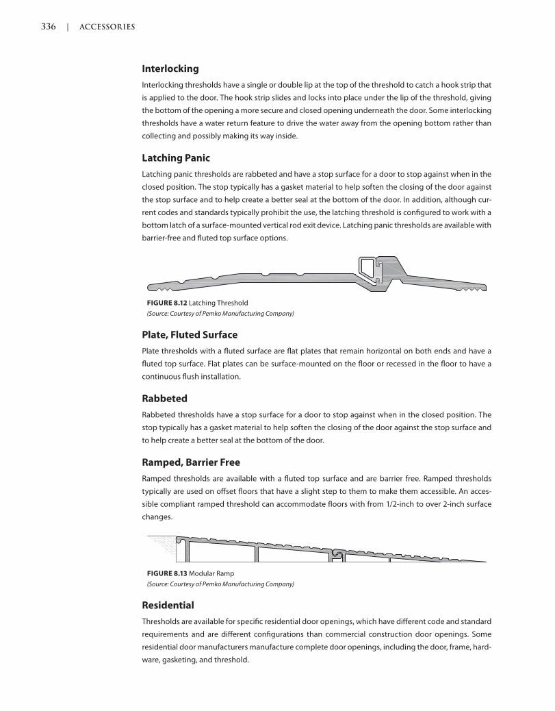
336 | ACCESSORIES
c08.indd Page 336 03/03/2015 05:6:30:PM
Interlocking
Interlocking thresholds have a single or double lip at the top of the threshold to catch a hook strip that
is applied to the door. The hook strip slides and locks into place under the lip of the threshold, giving
the bottom of the opening a more secure and closed opening underneath the door. Some interlocking
thresholds have a water return feature to drive the water away from the opening bottom rather than
collecting and possibly making its way inside.
Latching Panic
Latching panic thresholds are rabbeted and have a stop surface for a door to stop against when in the
closed position. The stop typically has a gasket material to help soften the closing of the door against
the stop surface and to help create a better seal at the bottom of the door. In addition, although cur-
rent codes and standards typically prohibit the use, the latching threshold is configured to work with a
bottom latch of a surface-mounted vertical rod exit device. Latching panic thresholds are available with
barrier-free and fluted top surface options.
FIGURE 8.12 Latching Threshold
(Source: Courtesy of Pemko Manufacturing Company)
Plate, Fluted Surface
Plate thresholds with a fluted surface are flat plates that remain horizontal on both ends and have a
fluted top surface. Flat plates can be surface-mounted on the floor or recessed in the floor to have a
continuous flush installation.
Rabbeted
Rabbeted thresholds have a stop surface for a door to stop against when in the closed position. The
stop typically has a gasket material to help soften the closing of the door against the stop surface and
to help create a better seal at the bottom of the door.
Ramped, Barrier Free
Ramped thresholds are available with a fluted top surface and are barrier free. Ramped thresholds
typically are used on offset floors that have a slight step to them to make them accessible. An acces-
sible compliant ramped threshold can accommodate floors with from 1/2-inch to over 2-inch surface
changes.
FIGURE 8.13 Modular Ramp
(Source: Courtesy of Pemko Manufacturing Company)
Residential
Thresholds are available for specific residential door openings, which have different code and standard
requirements and are different configurations than commercial construction door openings. Some
residential door manufacturers manufacture complete door openings, including the door, frame, hard-
ware, gasketing, and threshold.
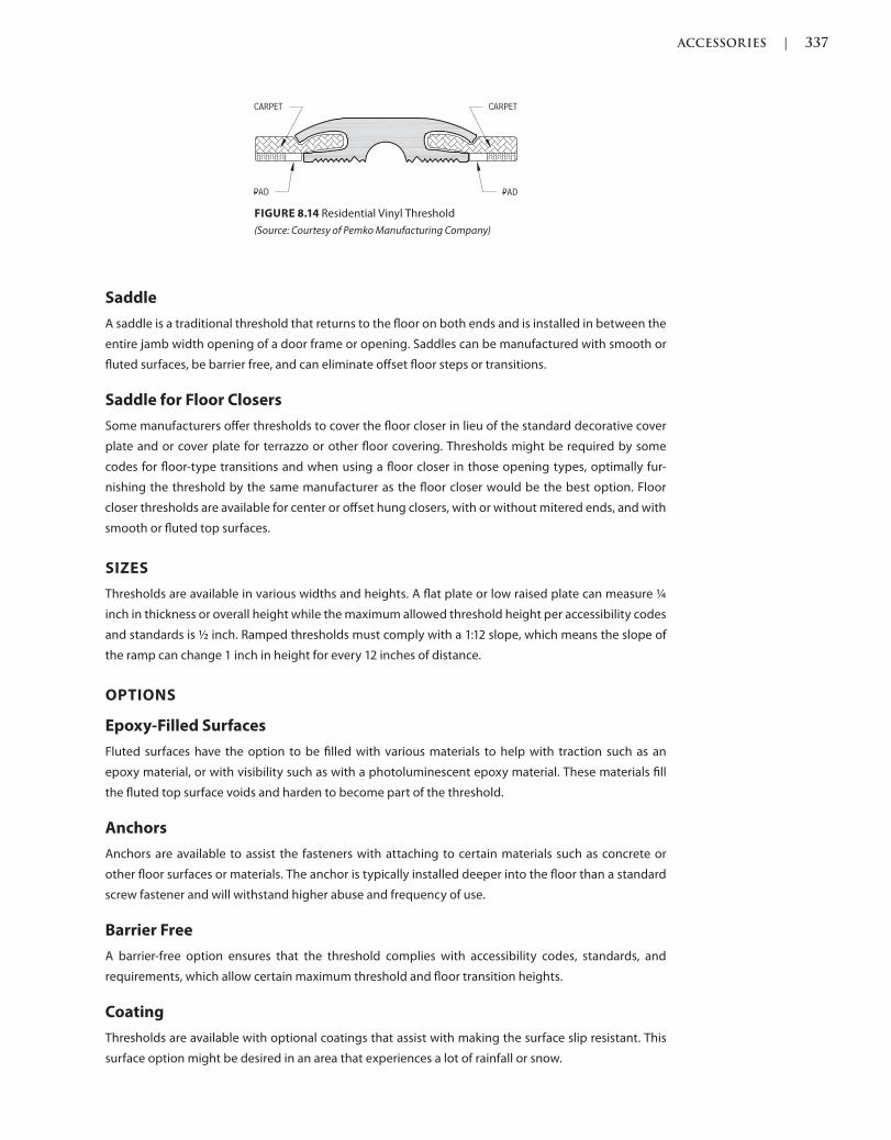
ACCESSORIES | 337
c08.indd Page 337 03/03/2015 05:6:30:PM
Saddle
A saddle is a traditional threshold that returns to the floor on both ends and is installed in between the
entire jamb width opening of a door frame or opening. Saddles can be manufactured with smooth or
fluted surfaces, be barrier free, and can eliminate offset floor steps or transitions.
Saddle for Floor Closers
Some manufacturers offer thresholds to cover the floor closer in lieu of the standard decorative cover
plate and or cover plate for terrazzo or other floor covering. Thresholds might be required by some
codes for floor-type transitions and when using a floor closer in those opening types, optimally fur-
nishing the threshold by the same manufacturer as the floor closer would be the best option. Floor
closer thresholds are available for center or offset hung closers, with or without mitered ends, and with
smooth or fluted top surfaces.
SIZES
Thresholds are available in various widths and heights. A flat plate or low raised plate can measure ¼
inch in thickness or overall height while the maximum allowed threshold height per accessibility codes
and standards is ½ inch. Ramped thresholds must comply with a 1:12 slope, which means the slope of
the ramp can change 1 inch in height for every 12 inches of distance.
OPTIONS
Epoxy-Filled Surfaces
Fluted surfaces have the option to be filled with various materials to help with traction such as an
epoxy material, or with visibility such as with a photoluminescent epoxy material. These materials fill
the fluted top surface voids and harden to become part of the threshold.
Anchors
Anchors are available to assist the fasteners with attaching to certain materials such as concrete or
other floor surfaces or materials. The anchor is typically installed deeper into the floor than a standard
screw fastener and will withstand higher abuse and frequency of use.
Barrier Free
A barrier-free option ensures that the threshold complies with accessibility codes, standards, and
requirements, which allow certain maximum threshold and floor transition heights.
Coating
Thresholds are available with optional coatings that assist with making the surface slip resistant. This
surface option might be desired in an area that experiences a lot of rainfall or snow.
FIGURE 8.14 Residential Vinyl Threshold
(Source: Courtesy of Pemko Manufacturing Company)
338 | ACCESSORIES
c08.indd Page 338 03/03/2015 05:6:30:PM
Cutouts
Thresholds might need to have cutouts for hardware such as dust-proof strikes or concealed vertical
rod exit device latches.
Systems
Thresholds, most commonly ramped thresholds, are available in systems, which are preconfigured
components made into their own solution to accommodate common field conditions and applications.
Sound Transmission Class (STC)
Sound transmission class (STC) ratings measure the sound through a partition such as a wall, ceiling,
and doors. (Some refer to the “C” as co-efficiency, but the correct term is “class.”) A standard rating, such
as speech through a wall, would be STC 25, while STC 30–35, a slightly higher rating, would muffle the
speech, although it still would be able to be heard. At STC 50, a band might be heard through a wall, but
most sounds are contained and not heard at a rating this high. Higher ratings are available by specialty
door manufacturers who specialize in heavy-duty sound attenuation.
QUANTITIES
Thresholds are furnished in single quantities and are specified one for each door required. This includes
adjustable or ramped component thresholds that might require multiple pieces to make the threshold
whole.
APPLICATIONS
Recessed
A flat plate threshold can be installed recessed in a floor so that it is flush with the floor creating a con-
tinuous surface.
Surface Mounted
Thresholds are typically installed surface-mounted on the floor or floor surface material.
INSTALLATION
It is typically recommended that a threshold be installed horizontally across the entire door width and
across the entire jamb width opening. For example, if installing a threshold into a hollow metal frame
with a 5 3/4-inch jamb width opening, a 4-inch-wide threshold would be inappropriate. Instead, a
product at least 6 inches wide would be installed.
Fasteners
Thresholds are typically installed with screw fasteners, which are available for installation on vari-
ous floor materials. If a heavy-duty or special application is required, other types of bolts and anchor
options are available to be specified and used for the installation.
Locations
Thresholds should typically be installed per the manufacturer’s recommendations and horizontally
between a door frame or door opening. They should cover the entire jamb width opening of the frame
or framed opening.
ACCESSORIES | 339
c08.indd Page 339 03/03/2015 05:6:30:PM
Preparations
Threshold preparations take place in the field by the installer, including the drilling and tapping of
screw holes, and any anchor or special fastener installation preparations.
WEATHERSTRIPPING AND GASKETING
Also Known As: Weatherstrip, Gasket, Seals, Sound/Weather/Light Seals, Sound/Weather/Light Gaskets
DESCRIPTION
Weatherstripping and gasketing are installed to cover or fill the clearance surrounding a door or doors
in a frame. Weatherstripping and gasketing are available in different configurations and are installed,
either surface-mounted or recessed, around the perimeter edge of a door. Weatherstripping and gas-
keting are recommended to be installed the entire height and width of a door and might be required
by certain codes or standards.
PROPERTIES
Finishes
Weatherstripping and gasketing are typically available in a limited number of architectural finishes and
should comply with ANSI/BHMA A156.18 American National Standard for Materials and Finishes, 2012.
Although some manufacturers might offer other options, the most typical astragal finishes available
are anodized aluminum, bronze, dark bronze, gold, and painted finishes. Astragals with gasket materi-
als are typically available in brown, black, gray, tan, and white and can be manufactured from foam,
neoprene, santoprene, silicone, brush, and other materials.
Grades
Weatherstripping is not categorized by grades and should comply with Test Requirements as described
in ANSI/BHMA A156.22 American National Standard for Door Gasketing and Edge Systems, 2005.
Materials
Weatherstripping housing can be manufactured with aluminum, brass, bronze, rubber, stainless
steel, steel, wood, or other suitable material. The weatherstripping material inserted into the hous-
ings can be manufactured of neoprene, brush, rubber, silicone, or santoprene (sustainable type)
material.
Some codes and standards require the use of intumescent materials, which expand when heated to
a certain degree to seal and close any gaps surrounding an opening. Intumescent materials can be
installed two ways, either on the frame or as part of the construction of a wood door edge, hidden
behind the finished wood veneer.
TYPES
Weatherstripping and gasketing are available in various types, which can be manufactured from dif-
ferent materials, in various sizes, using different mounting methods. ANSI/BHMA A156.22 American
National Standard for Door Gasketing and Edge Seal Systems, 2005 describes the basic types.
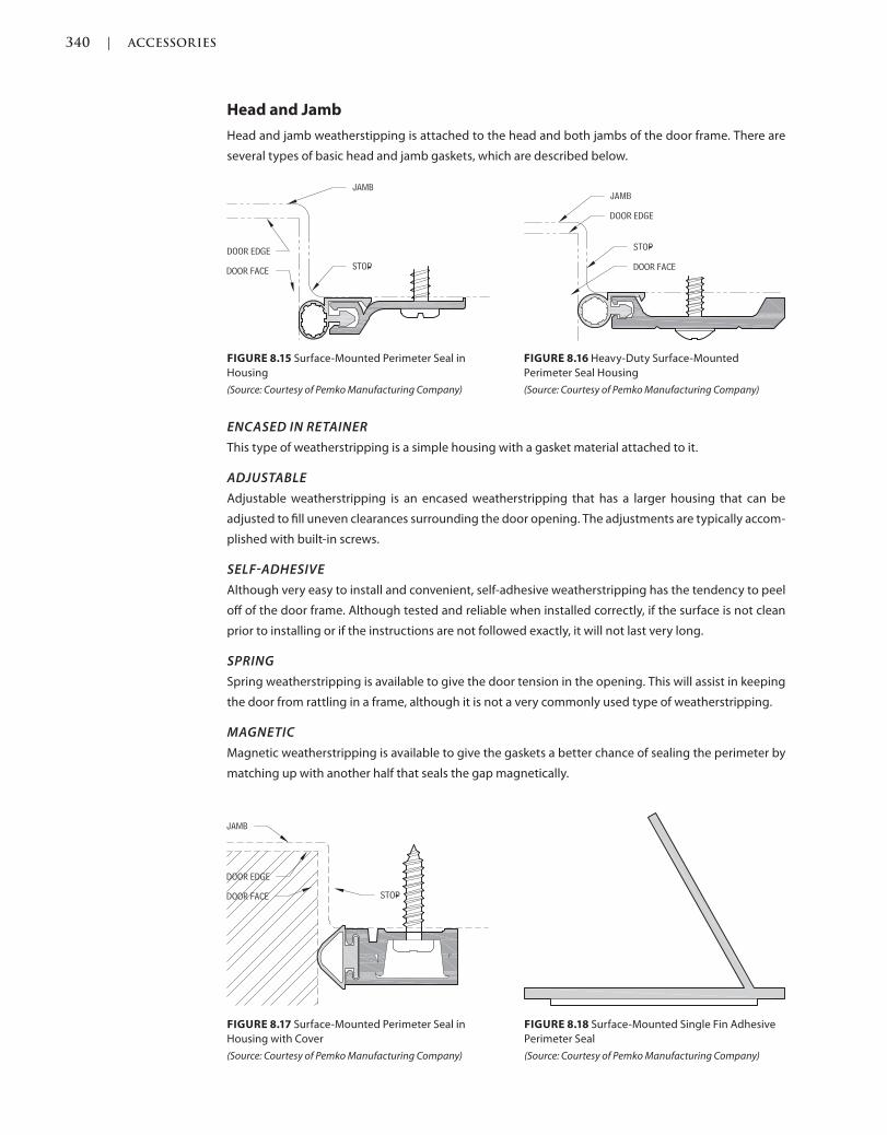
340 | ACCESSORIES
c08.indd Page 340 03/03/2015 05:6:30:PM
Head and Jamb
Head and jamb weatherstipping is attached to the head and both jambs of the door frame. There are
several types of basic head and jamb gaskets, which are described below.
FIGURE 8.15 Surface-Mounted Perimeter Seal in
Housing
(Source: Courtesy of Pemko Manufacturing Company)
FIGURE 8.17 Surface-Mounted Perimeter Seal in
Housing with Cover
(Source: Courtesy of Pemko Manufacturing Company)
FIGURE 8.16 Heavy-Duty Surface-Mounted
Perimeter Seal Housing
(Source: Courtesy of Pemko Manufacturing Company)
FIGURE 8.18 Surface-Mounted Single Fin Adhesive
Perimeter Seal
(Source: Courtesy of Pemko Manufacturing Company)
ENCASED IN RETAINER
This type of weatherstripping is a simple housing with a gasket material attached to it.
ADJUSTABLE
Adjustable weatherstripping is an encased weatherstripping that has a larger housing that can be
adjusted to fill uneven clearances surrounding the door opening. The adjustments are typically accom-
plished with built-in screws.
SELFADHESIVE
Although very easy to install and convenient, self-adhesive weatherstripping has the tendency to peel
off of the door frame. Although tested and reliable when installed correctly, if the surface is not clean
prior to installing or if the instructions are not followed exactly, it will not last very long.
SPRING
Spring weatherstripping is available to give the door tension in the opening. This will assist in keeping
the door from rattling in a frame, although it is not a very commonly used type of weatherstripping.
MAGNETIC
Magnetic weatherstripping is available to give the gaskets a better chance of sealing the perimeter by
matching up with another half that seals the gap magnetically.
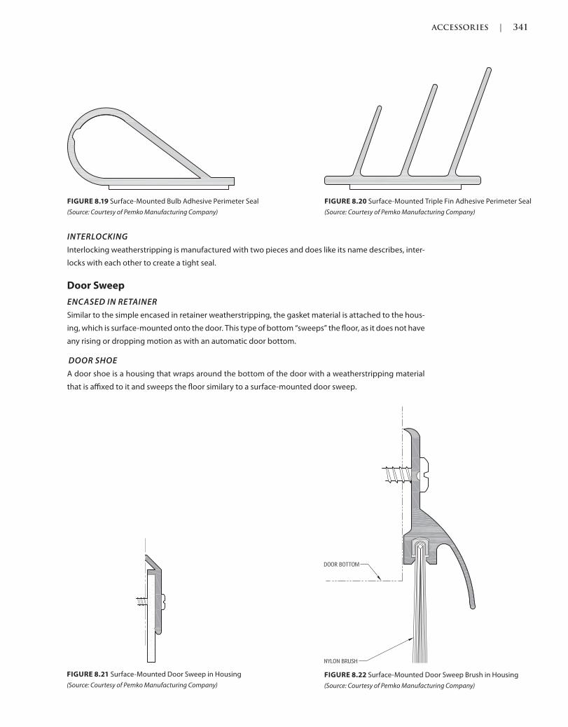
ACCESSORIES | 341
c08.indd Page 341 03/03/2015 05:6:30:PM
INTERLOCKING
Interlocking weatherstripping is manufactured with two pieces and does like its name describes, inter-
locks with each other to create a tight seal.
Door Sweep
ENCASED IN RETAINER
Similar to the simple encased in retainer weatherstripping, the gasket material is attached to the hous-
ing, which is surface-mounted onto the door. This type of bottom “sweeps” the floor, as it does not have
any rising or dropping motion as with an automatic door bottom.
DOOR SHOE
A door shoe is a housing that wraps around the bottom of the door with a weatherstripping material
that is affixed to it and sweeps the floor similary to a surface-mounted door sweep.
FIGURE 8.19 Surface-Mounted Bulb Adhesive Perimeter Seal
(Source: Courtesy of Pemko Manufacturing Company)
FIGURE 8.20 Surface-Mounted Triple Fin Adhesive Perimeter Seal
(Source: Courtesy of Pemko Manufacturing Company)
FIGURE 8.21 Surface-Mounted Door Sweep in Housing
(Source: Courtesy of Pemko Manufacturing Company)
FIGURE 8.22 Surface-Mounted Door Sweep Brush in Housing
(Source: Courtesy of Pemko Manufacturing Company)

342 | ACCESSORIES
c08.indd Page 342 03/03/2015 05:6:30:PM
DOOR SHOE WITH DRIP CAP
A door shoe with a drip cap is similar to a door shoe that has a housing that wraps around the bot-
tom of the door with a weatherstripping material that is affixed to it and sweeps the floor similar to
a surface-mounted door sweep. In addition, there is a curved material that helps with keeping water
and other substances away from the clearance at the bottom of the door so it does not to get inside
the structure.
AUTOMATIC ENCASED IN RETAINER/SURFACE
A surface-mounted automatic door bottom is surface-mounted on the push side face of the door
when it is hung in a door frame, and drops down to seal the bottom clearance when the door is
in the closed position and rises up when in the open position. There is a small trigger that when
depressed, causes the bottom to drop down; this is why it is important that the automatic door bot-
tom is installed on the push side face of the door, so that the trigger is depressed on the frame soffit
when the door closes.
FIGURE 8.23 Surface-Mounted Half-Door Shoe
(Source: Courtesy of Pemko Manufacturing Company)
FIGURE 8.24 Surface-Mounted Full Door Shoe
(Source: Courtesy of Pemko Manufacturing Company)
FIGURE 8.25 Door Shoe with Drip Cap
(Source: Courtesy of Pemko Manufacturing Company)
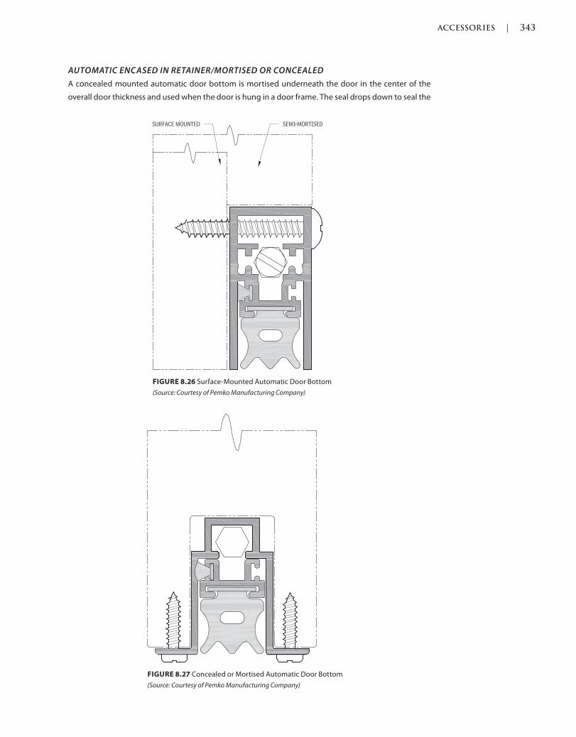
ACCESSORIES | 343
c08.indd Page 343 03/03/2015 05:6:30:PM
AUTOMATIC ENCASED IN RETAINER/MORTISED OR CONCEALED
A concealed mounted automatic door bottom is mortised underneath the door in the center of the
overall door thickness and used when the door is hung in a door frame. The seal drops down to seal the
FIGURE 8.26 Surface-Mounted Automatic Door Bottom
(Source: Courtesy of Pemko Manufacturing Company)
FIGURE 8.27 Concealed or Mortised Automatic Door Bottom
(Source: Courtesy of Pemko Manufacturing Company)
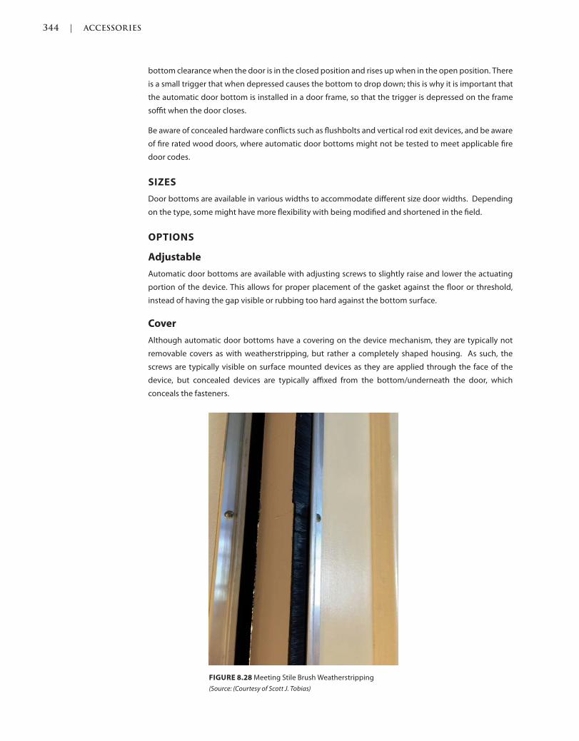
344 | ACCESSORIES
c08.indd Page 344 03/03/2015 05:6:30:PM
bottom clearance when the door is in the closed position and rises up when in the open position. There
is a small trigger that when depressed causes the bottom to drop down; this is why it is important that
the automatic door bottom is installed in a door frame, so that the trigger is depressed on the frame
soffit when the door closes.
Be aware of concealed hardware conflicts such as flushbolts and vertical rod exit devices, and be aware
of fire rated wood doors, where automatic door bottoms might not be tested to meet applicable fire
door codes.
SIZES
Door bottoms are available in various widths to accommodate different size door widths. Depending
on the type, some might have more flexibility with being modified and shortened in the field.
OPTIONS
Adjustable
Automatic door bottoms are available with adjusting screws to slightly raise and lower the actuating
portion of the device. This allows for proper placement of the gasket against the floor or threshold,
instead of having the gap visible or rubbing too hard against the bottom surface.
Cover
Although automatic door bottoms have a covering on the device mechanism, they are typically not
removable covers as with weatherstripping, but rather a completely shaped housing. As such, the
screws are typically visible on surface mounted devices as they are applied through the face of the
device, but concealed devices are typically affixed from the bottom/underneath the door, which
conceals the fasteners.
FIGURE 8.28 Meeting Stile Brush Weatherstripping
(Source: (Courtesy of Scott J. Tobias)
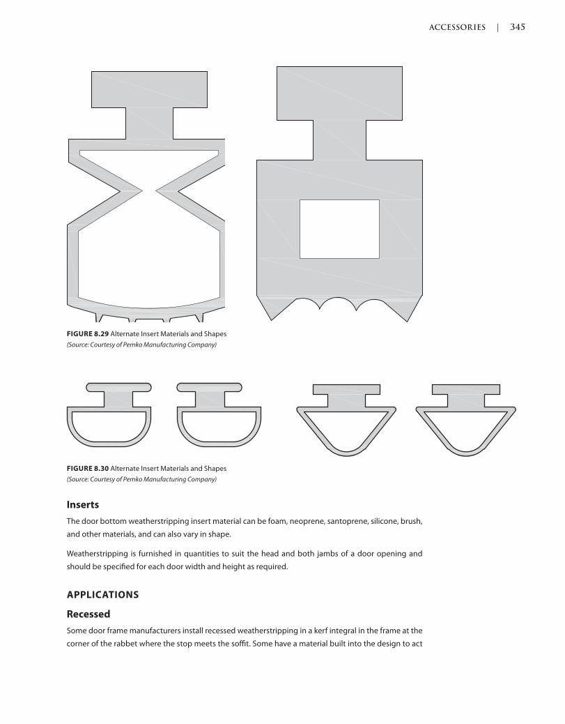
ACCESSORIES | 345
c08.indd Page 345 03/03/2015 05:6:30:PM
Inserts
The door bottom weatherstripping insert material can be foam, neoprene, santoprene, silicone, brush,
and other materials, and can also vary in shape.
Weatherstripping is furnished in quantities to suit the head and both jambs of a door opening and
should be specified for each door width and height as required.
APPLICATIONS
Recessed
Some door frame manufacturers install recessed weatherstripping in a kerf integral in the frame at the
corner of the rabbet where the stop meets the soffit. Some have a material built into the design to act
FIGURE 8.30 Alternate Insert Materials and Shapes
(Source: Courtesy of Pemko Manufacturing Company)
FIGURE 8.29 Alternate Insert Materials and Shapes
(Source: Courtesy of Pemko Manufacturing Company)
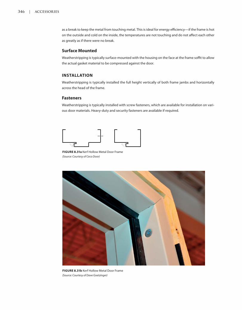
346 | ACCESSORIES
c08.indd Page 346 03/03/2015 05:6:30:PM
as a break to keep the metal from touching metal. This is ideal for energy efficiency—if the frame is hot
on the outside and cold on the inside, the temperatures are not touching and do not affect each other
as greatly as if there were no break.
Surface Mounted
Weatherstripping is typically surface-mounted with the housing on the face at the frame soffit to allow
the actual gasket material to be compressed against the door.
INSTALLATION
Weatherstripping is typically installed the full height vertically of both frame jambs and horizontally
across the head of the frame.
Fasteners
Weatherstripping is typically installed with screw fasteners, which are available for installation on vari-
ous door materials. Heavy-duty and security fasteners are available if required.
FIGURE 8.31b Kerf Hollow Metal Door Frame
(Source: Courtesy of Dave Goetzinger)
FIGURE 8.31a Kerf Hollow Metal Door Frame
(Source: Courtesy of Ceco Door)
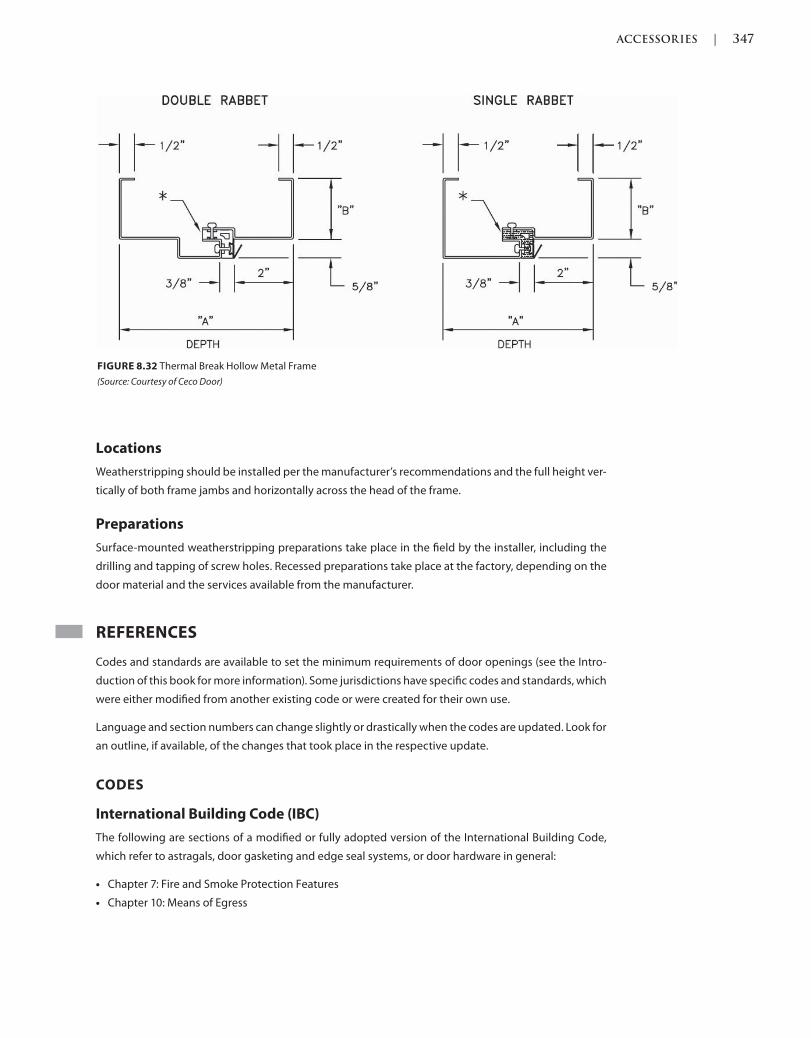
ACCESSORIES | 347
c08.indd Page 347 03/03/2015 05:6:30:PM
Locations
Weatherstripping should be installed per the manufacturer’s recommendations and the full height ver-
tically of both frame jambs and horizontally across the head of the frame.
Preparations
Surface-mounted weatherstripping preparations take place in the field by the installer, including the
drilling and tapping of screw holes. Recessed preparations take place at the factory, depending on the
door material and the services available from the manufacturer.
REFERENCES
Codes and standards are available to set the minimum requirements of door openings (see the Intro-
duction of this book for more information). Some jurisdictions have specific codes and standards, which
were either modified from another existing code or were created for their own use.
Language and section numbers can change slightly or drastically when the codes are updated. Look for
an outline, if available, of the changes that took place in the respective update.
CODES
International Building Code (IBC)
The following are sections of a modified or fully adopted version of the International Building Code,
which refer to astragals, door gasketing and edge seal systems, or door hardware in general:
Chapter 7: Fire and Smoke Protection Features
Chapter 10: Means of Egress
FIGURE 8.32 Thermal Break Hollow Metal Frame
(Source: Courtesy of Ceco Door)
348 | ACCESSORIES
c08.indd Page 348 03/03/2015 05:6:30:PM
National Fire Protection Association (NFPA) 101: Life Safety Code
The following is a chapter of a modified or fully adopted version of the NFPA 101: Life Safety Code,
which refers to astragals, door gasketing and edge seal systems, or door hardware in general:
Chapter 7: Means of Egress
STANDARDS
ADA Accessibility Guidelines for Buildings and Facilities (ADAAG)
The following is a chapter of a modified or fully adopted version of the ADA Accessibility Guidelines for
Buildings and Facilities, which refers to astragals, door gasketing and edge seal systems, or door hard-
ware in general: Chapter 4: Accessible Routes
American National Standards Institute (ANSI) S12.60 Acoustical
Performance Criteria, Design Requirements and Guidelines for Schools
This standard identifies requirements for sound in various types of schools and school settings, and is
required by LEED v2009 for Schools.
ASTM International (ASTM)
There are hundreds of ASTM International testing standards that are related to doors and door hard-
ware, from material and assembly testing to installation and application testing.
ASTM E90—Standard Test Method for Laboratory Measurement of Airborne Sound Transmission Loss
of Building Partitions and Elements
ASTM E413—Classification for Rating Sound Insulation
ASTM E1332—Standard Classification for Rating Outdoor-Indoor Sound Attenuation
ASTM E2235—Standard Test Method for Determination of Decay Rates for Use in Sound Insulation Test
Methods
Door and Hardware Institute (DHI)
The following are technical documents available for reference that refer to astragals, door gasketing
and edge seal systems, or door hardware in general:
Abbreviations and Symbols
Basic Architectural Hardware
Hardware for Healthcare Facilities
Installation Guide for Doors and Hardware
Processing Hardware for Custom Aluminum Entrances
Recommended Locations for Builders Hardware Custom Steel Doors & Frames
Recommended Locations for Architectural Hardware for Standard Steel Doors & Frames
Recommended Locations for Architectural Hardware for Flush Wood Doors
Recommended Procedures for Processing Hardware Schedules and Templates
Sequence and Format for the Hardware Schedule
Tech Talk WS-1/Rev Gasketing and Thresholds

ACCESSORIES | 349
c08.indd Page 349 03/03/2015 05:6:30:PM
Leadership in Energy and Environmental Design (LEED)
The USGBC created the LEED rating system, which is a volunteer rating system for construction build-
ings. LEED stands for Leadership in Energy and Environmental Design and has been the platform for
mandatory adoption and code creation. This standard addresses sustainability, energy efficiency,
human health, and saving the earth’s resources for future generations.
National Fire Protection Association (NFPA)
Following are chapters of a modified or fully adopted version of NFPA 80: Standard for Fire Doors and
Other Opening Protectives, which refer to astragals, door gasketing and edge seal systems, or door
hardware in general:
Chapter 5: Care and Maintenance
Chapter 6: Swinging Doors with Builders Hardware
Chapter 7: Swinging Doors with Fire Door Hardware
Chapter 8: Horizontally Sliding Doors
Chapter 9: Special-Purpose Horizontally Sliding Accordion or Folding Doors
Chapter 16: Access Doors
Chapter 19: Installation, Testing, and Maintenance of Fire Dampers
Annex A: Explanatory Material
The Following is a chapter of a modified or fully adopted version of NFPA 105: Standard for Smoke Door
Assemblies and Other Opening Protectives, which refers to astragals, door gasketing and edge seal
systems, or door hardware in general:
Chapter 6: Installation, Testing, and Maintenance of Smoke Dampers
The following is a chapter of a modified or fully adopted version of NFPA 252: Standard Method of Fire
Tests of Door Assemblies, which refers to astragals, door gasketing and edge seal systems, or door
hardware in general:
Chapter 5: Fire Door Assembly
Annex B: Commentary
American National Standards Institute/Builders Hardware Manufacturers
Association (ANSI/BHMA)
The following are standards that refer to astragals, door gasketing and edge seal systems, or door hard-
ware in general:
ANSI/BHMA A156.22 American National Standard for Door Gasketing and Edge Seal Systems
ANSI/BHMA A156.18 American National Standard for Materials and Finishes
Underwriters Laboratory (UL)
UL is an independent safety company innovating solutions for many of the items that we use every
day, from electricity to sustainability and renewable energy. UL is dedicated to testing for safe envi-
ronments to help safeguard people and there are many UL standards that affect doors and door
hardware.

350 | ACCESSORIES
c08.indd Page 350 03/03/2015 05:6:30:PM
The following are sections of a modified or fully adopted version of UL that refer to astragals, door gas-
keting and edge seal systems, or door hardware in general:
UL 10B, Fire Tests of Door Assemblies
UL 10C, Positive Pressure Fire Tests of Door Assemblies
UL1784, Air Leakage Test of Door Assemblies
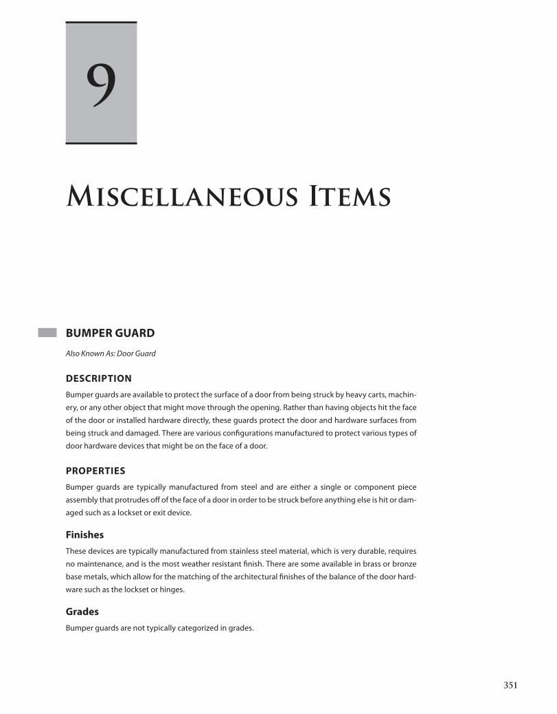
351
c09.indd Page 351 03/03/2015 04:35:2:PM
BUMPER GUARD
Also Known As: Door Guard
DESCRIPTION
Bumper guards are available to protect the surface of a door from being struck by heavy carts, machin-
ery, or any other object that might move through the opening. Rather than having objects hit the face
of the door or installed hardware directly, these guards protect the door and hardware surfaces from
being struck and damaged. There are various configurations manufactured to protect various types of
door hardware devices that might be on the face of a door.
PROPERTIES
Bumper guards are typically manufactured from steel and are either a single or component piece
assembly that protrudes off of the face of a door in order to be struck before anything else is hit or dam-
aged such as a lockset or exit device.
Finishes
These devices are typically manufactured from stainless steel material, which is very durable, requires
no maintenance, and is the most weather resistant finish. There are some available in brass or bronze
base metals, which allow for the matching of the architectural finishes of the balance of the door hard-
ware such as the lockset or hinges.
Grades
Bumper guards are not typically categorized in grades.
Miscellaneous Items
9
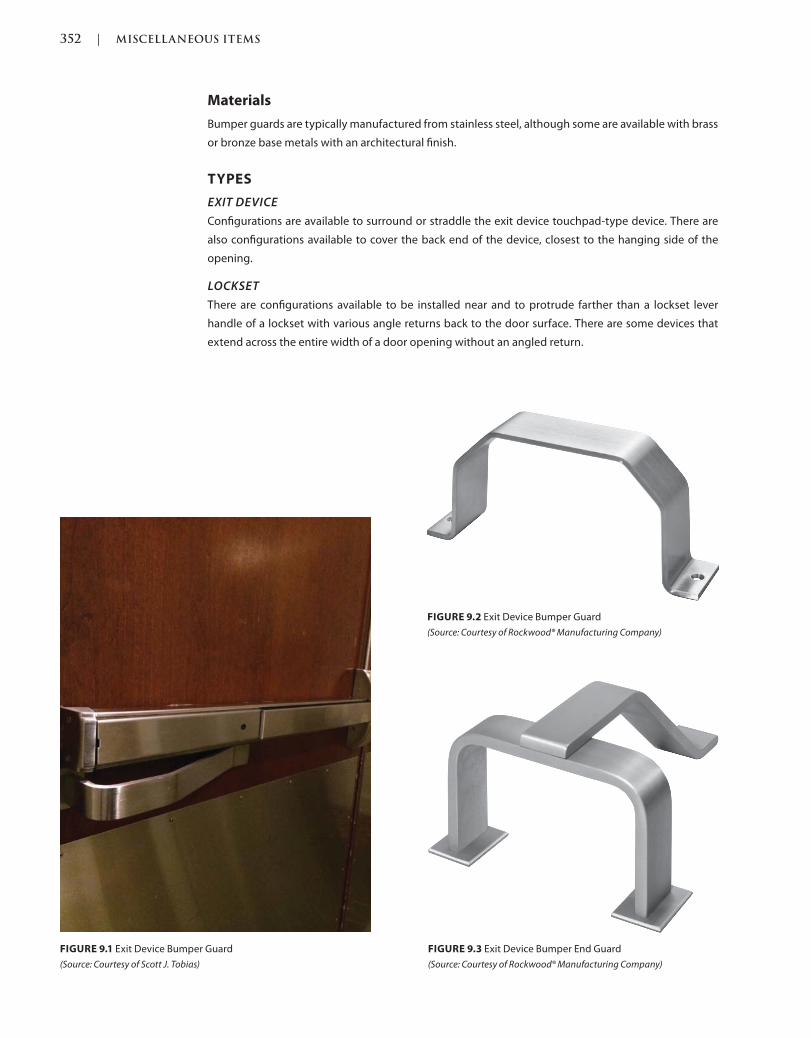
352 | MISCELLANEOUS ITEMS
c09.indd Page 352 03/03/2015 04:35:2:PM
Materials
Bumper guards are typically manufactured from stainless steel, although some are available with brass
or bronze base metals with an architectural finish.
TYPES
EXIT DEVICE
Configurations are available to surround or straddle the exit device touchpad-type device. There are
also configurations available to cover the back end of the device, closest to the hanging side of the
opening.
LOCKSET
There are configurations available to be installed near and to protrude farther than a lockset lever
handle of a lockset with various angle returns back to the door surface. There are some devices that
extend across the entire width of a door opening without an angled return.
FIGURE 9.1 Exit Device Bumper Guard
(Source: Courtesy of Scott J. Tobias)
FIGURE 9.2 Exit Device Bumper Guard
(Source: Courtesy of Rockwood® Manufacturing Company)
FIGURE 9.3 Exit Device Bumper End Guard
(Source: Courtesy of Rockwood® Manufacturing Company)
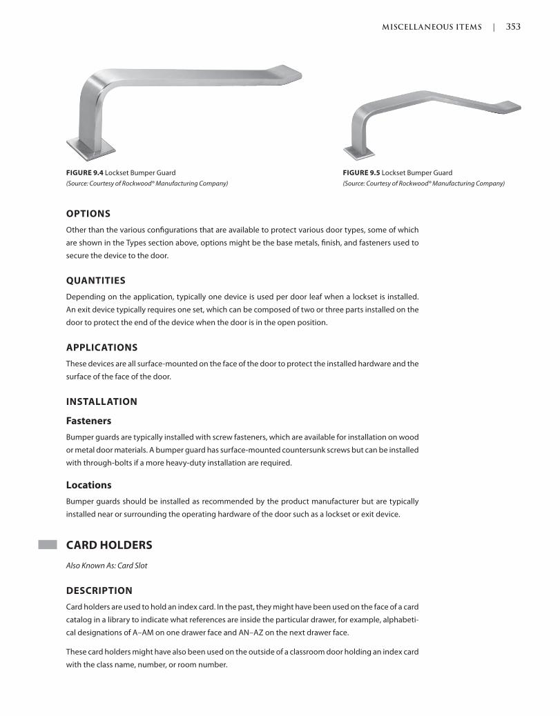
MISCELLANEOUS ITEMS | 353
c09.indd Page 353 03/03/2015 04:35:2:PM
OPTIONS
Other than the various configurations that are available to protect various door types, some of which
are shown in the Types section above, options might be the base metals, finish, and fasteners used to
secure the device to the door.
QUANTITIES
Depending on the application, typically one device is used per door leaf when a lockset is installed.
An exit device typically requires one set, which can be composed of two or three parts installed on the
door to protect the end of the device when the door is in the open position.
APPLICATIONS
These devices are all surface-mounted on the face of the door to protect the installed hardware and the
surface of the face of the door.
INSTALLATION
Fasteners
Bumper guards are typically installed with screw fasteners, which are available for installation on wood
or metal door materials. A bumper guard has surface-mounted countersunk screws but can be installed
with through-bolts if a more heavy-duty installation are required.
Locations
Bumper guards should be installed as recommended by the product manufacturer but are typically
installed near or surrounding the operating hardware of the door such as a lockset or exit device.
CARD HOLDERS
Also Known As: Card Slot
DESCRIPTION
Card holders are used to hold an index card. In the past, they might have been used on the face of a card
catalog in a library to indicate what references are inside the particular drawer, for example, alphabeti-
cal designations of A–AM on one drawer face and AN–AZ on the next drawer face.
These card holders might have also been used on the outside of a classroom door holding an index card
with the class name, number, or room number.
FIGURE 9.4 Lockset Bumper Guard
(Source: Courtesy of Rockwood® Manufacturing Company)
FIGURE 9.5 Lockset Bumper Guard
(Source: Courtesy of Rockwood® Manufacturing Company)
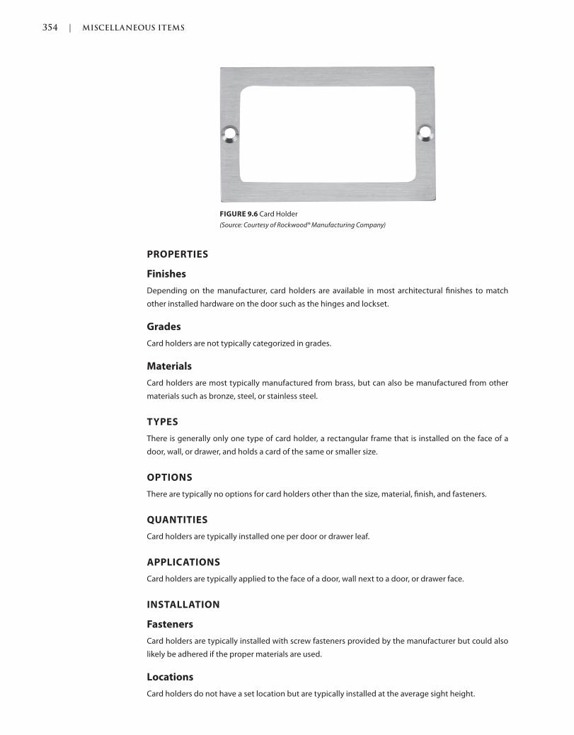
354 | MISCELLANEOUS ITEMS
c09.indd Page 354 03/03/2015 04:35:2:PM
PROPERTIES
Finishes
Depending on the manufacturer, card holders are available in most architectural finishes to match
other installed hardware on the door such as the hinges and lockset.
Grades
Card holders are not typically categorized in grades.
Materials
Card holders are most typically manufactured from brass, but can also be manufactured from other
materials such as bronze, steel, or stainless steel.
TYPES
There is generally only one type of card holder, a rectangular frame that is installed on the face of a
door, wall, or drawer, and holds a card of the same or smaller size.
OPTIONS
There are typically no options for card holders other than the size, material, finish, and fasteners.
QUANTITIES
Card holders are typically installed one per door or drawer leaf.
APPLICATIONS
Card holders are typically applied to the face of a door, wall next to a door, or drawer face.
INSTALLATION
Fasteners
Card holders are typically installed with screw fasteners provided by the manufacturer but could also
likely be adhered if the proper materials are used.
Locations
Card holders do not have a set location but are typically installed at the average sight height.
FIGURE 9.6 Card Holder
(Source: Courtesy of Rockwood® Manufacturing Company)

MISCELLANEOUS ITEMS | 355
c09.indd Page 355 03/03/2015 04:35:2:PM
COAT HOOKS
Also Known As: Door Hook, Robe Hook, Clothes Hook, Towel Hook
DESCRIPTION
Coat hooks are typically mounted on the backside or room side of a door where you might hang a coat.
They might be specified on the back of private or hotel bathroom doors to hold towels or a bathrobe.
FIGURE 9.7 Coat Hook
(Source: Courtesy of Rockwood® Manufacturing Company)
FIGURE 9.8 Coat Hook
(Source: Courtesy of Rockwood® Manufacturing Company)
FIGURE 9.10 Coat Hook
(Source: Courtesy of Rockwood® Manufacturing Company)
FIGURE 9.9 Coat Hook
(Source: Courtesy of Rockwood® Manufacturing Company)
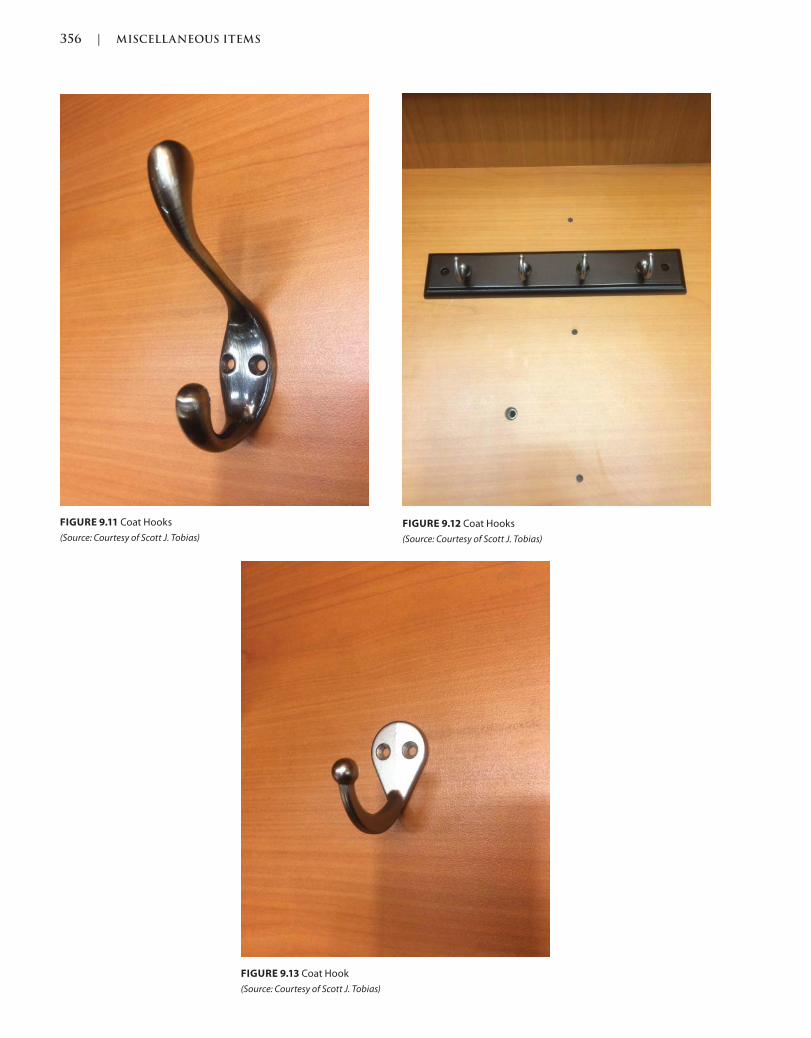
356 | MISCELLANEOUS ITEMS
c09.indd Page 356 03/03/2015 04:35:2:PM
FIGURE 9.12 Coat Hooks
(Source: Courtesy of Scott J. Tobias)
FIGURE 9.11 Coat Hooks
(Source: Courtesy of Scott J. Tobias)
FIGURE 9.13 Coat Hook
(Source: Courtesy of Scott J. Tobias)
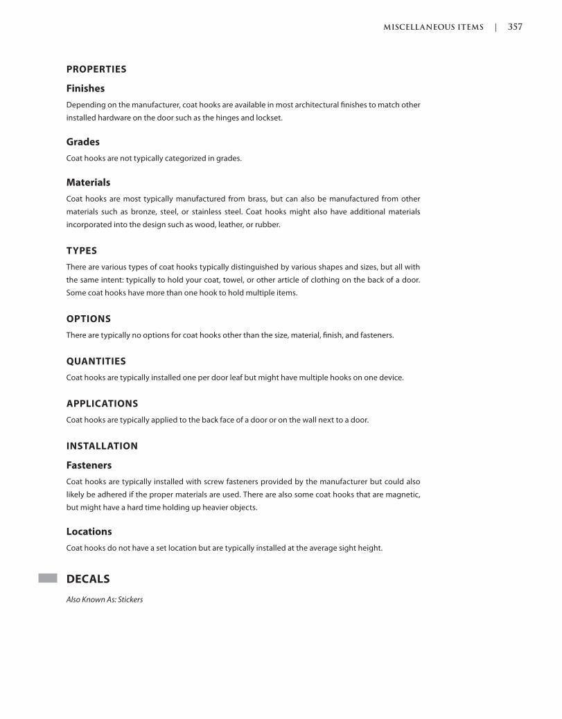
MISCELLANEOUS ITEMS | 357
c09.indd Page 357 03/03/2015 04:35:2:PM
PROPERTIES
Finishes
Depending on the manufacturer, coat hooks are available in most architectural finishes to match other
installed hardware on the door such as the hinges and lockset.
Grades
Coat hooks are not typically categorized in grades.
Materials
Coat hooks are most typically manufactured from brass, but can also be manufactured from other
materials such as bronze, steel, or stainless steel. Coat hooks might also have additional materials
incorporated into the design such as wood, leather, or rubber.
TYPES
There are various types of coat hooks typically distinguished by various shapes and sizes, but all with
the same intent: typically to hold your coat, towel, or other article of clothing on the back of a door.
Some coat hooks have more than one hook to hold multiple items.
OPTIONS
There are typically no options for coat hooks other than the size, material, finish, and fasteners.
QUANTITIES
Coat hooks are typically installed one per door leaf but might have multiple hooks on one device.
APPLICATIONS
Coat hooks are typically applied to the back face of a door or on the wall next to a door.
INSTALLATION
Fasteners
Coat hooks are typically installed with screw fasteners provided by the manufacturer but could also
likely be adhered if the proper materials are used. There are also some coat hooks that are magnetic,
but might have a hard time holding up heavier objects.
Locations
Coat hooks do not have a set location but are typically installed at the average sight height.
DECALS
Also Known As: Stickers
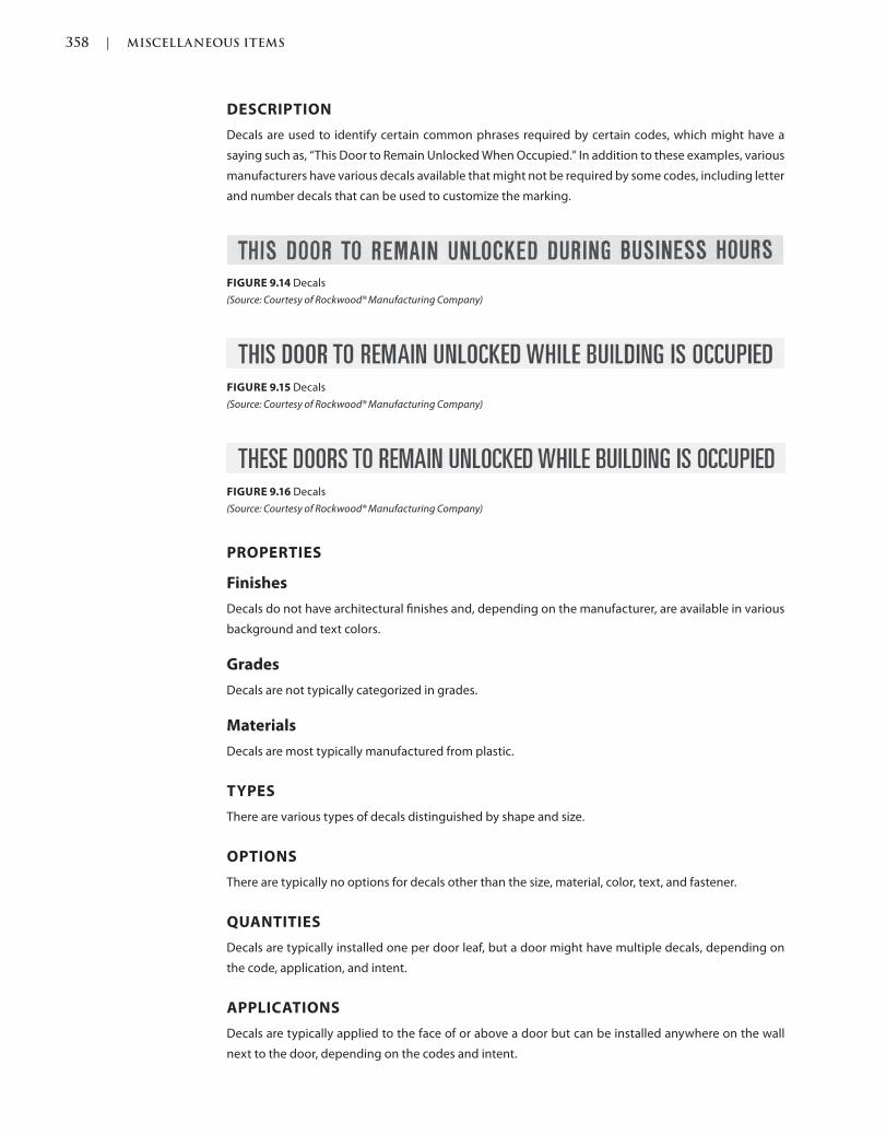
358 | MISCELLANEOUS ITEMS
c09.indd Page 358 03/03/2015 04:35:2:PM
DESCRIPTION
Decals are used to identify certain common phrases required by certain codes, which might have a
saying such as, “This Door to Remain Unlocked When Occupied.” In addition to these examples, various
manufacturers have various decals available that might not be required by some codes, including letter
and number decals that can be used to customize the marking.
FIGURE 9.16 Decals
(Source: Courtesy of Rockwood® Manufacturing Company)
FIGURE 9.14 Decals
(Source: Courtesy of Rockwood® Manufacturing Company)
FIGURE 9.15 Decals
(Source: Courtesy of Rockwood® Manufacturing Company)
PROPERTIES
Finishes
Decals do not have architectural finishes and, depending on the manufacturer, are available in various
background and text colors.
Grades
Decals are not typically categorized in grades.
Materials
Decals are most typically manufactured from plastic.
TYPES
There are various types of decals distinguished by shape and size.
OPTIONS
There are typically no options for decals other than the size, material, color, text, and fastener.
QUANTITIES
Decals are typically installed one per door leaf, but a door might have multiple decals, depending on
the code, application, and intent.
APPLICATIONS
Decals are typically applied to the face of or above a door but can be installed anywhere on the wall
next to the door, depending on the codes and intent.
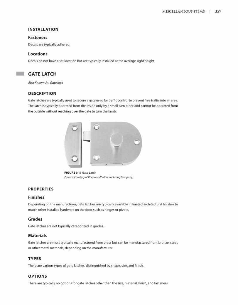
MISCELLANEOUS ITEMS | 359
c09.indd Page 359 03/03/2015 04:35:2:PM
INSTALLATION
Fasteners
Decals are typically adhered.
Locations
Decals do not have a set location but are typically installed at the average sight height.
GATE LATCH
Also Known As: Gate lock
DESCRIPTION
Gate latches are typically used to secure a gate used for traffic control to prevent free traffic into an area.
The latch is typically operated from the inside only by a small turn piece and cannot be operated from
the outside without reaching over the gate to turn the knob.
FIGURE 9.17 Gate Latch
(Source: Courtesy of Rockwood® Manufacturing Company)
PROPERTIES
Finishes
Depending on the manufacturer, gate latches are typically available in limited architectural finishes to
match other installed hardware on the door such as hinges or pivots.
Grades
Gate latches are not typically categorized in grades.
Materials
Gate latches are most typically manufactured from brass but can be manufactured from bronze, steel,
or other metal materials, depending on the manufacturer.
TYPES
There are various types of gate latches, distinguished by shape, size, and finish.
OPTIONS
There are typically no options for gate latches other than the size, material, finish, and fasteners.
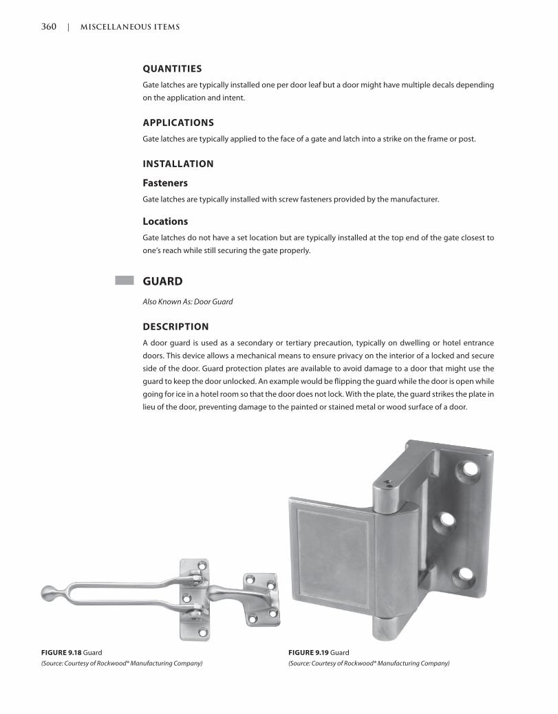
360 | MISCELLANEOUS ITEMS
c09.indd Page 360 03/03/2015 04:35:2:PM
QUANTITIES
Gate latches are typically installed one per door leaf but a door might have multiple decals depending
on the application and intent.
APPLICATIONS
Gate latches are typically applied to the face of a gate and latch into a strike on the frame or post.
INSTALLATION
Fasteners
Gate latches are typically installed with screw fasteners provided by the manufacturer.
Locations
Gate latches do not have a set location but are typically installed at the top end of the gate closest to
one’s reach while still securing the gate properly.
GUARD
Also Known As: Door Guard
DESCRIPTION
A door guard is used as a secondary or tertiary precaution, typically on dwelling or hotel entrance
doors. This device allows a mechanical means to ensure privacy on the interior of a locked and secure
side of the door. Guard protection plates are available to avoid damage to a door that might use the
guard to keep the door unlocked. An example would be flipping the guard while the door is open while
going for ice in a hotel room so that the door does not lock. With the plate, the guard strikes the plate in
lieu of the door, preventing damage to the painted or stained metal or wood surface of a door.
FIGURE 9.18 Guard
(Source: Courtesy of Rockwood® Manufacturing Company)
FIGURE 9.19 Guard
(Source: Courtesy of Rockwood® Manufacturing Company)
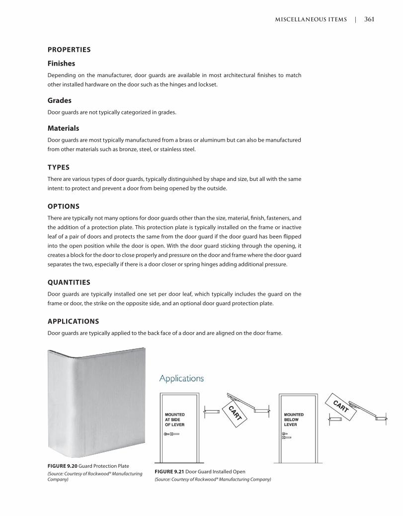
MISCELLANEOUS ITEMS | 361
c09.indd Page 361 03/03/2015 04:35:2:PM
PROPERTIES
Finishes
Depending on the manufacturer, door guards are available in most architectural finishes to match
other installed hardware on the door such as the hinges and lockset.
Grades
Door guards are not typically categorized in grades.
Materials
Door guards are most typically manufactured from a brass or aluminum but can also be manufactured
from other materials such as bronze, steel, or stainless steel.
TYPES
There are various types of door guards, typically distinguished by shape and size, but all with the same
intent: to protect and prevent a door from being opened by the outside.
OPTIONS
There are typically not many options for door guards other than the size, material, finish, fasteners, and
the addition of a protection plate. This protection plate is typically installed on the frame or inactive
leaf of a pair of doors and protects the same from the door guard if the door guard has been flipped
into the open position while the door is open. With the door guard sticking through the opening, it
creates a block for the door to close properly and pressure on the door and frame where the door guard
separates the two, especially if there is a door closer or spring hinges adding additional pressure.
QUANTITIES
Door guards are typically installed one set per door leaf, which typically includes the guard on the
frame or door, the strike on the opposite side, and an optional door guard protection plate.
APPLICATIONS
Door guards are typically applied to the back face of a door and are aligned on the door frame.
FIGURE 9.20 Guard Protection Plate
(Source: Courtesy of Rockwood® Manufacturing Company)
FIGURE 9.21 Door Guard Installed Open
(Source: Courtesy of Rockwood® Manufacturing Company)
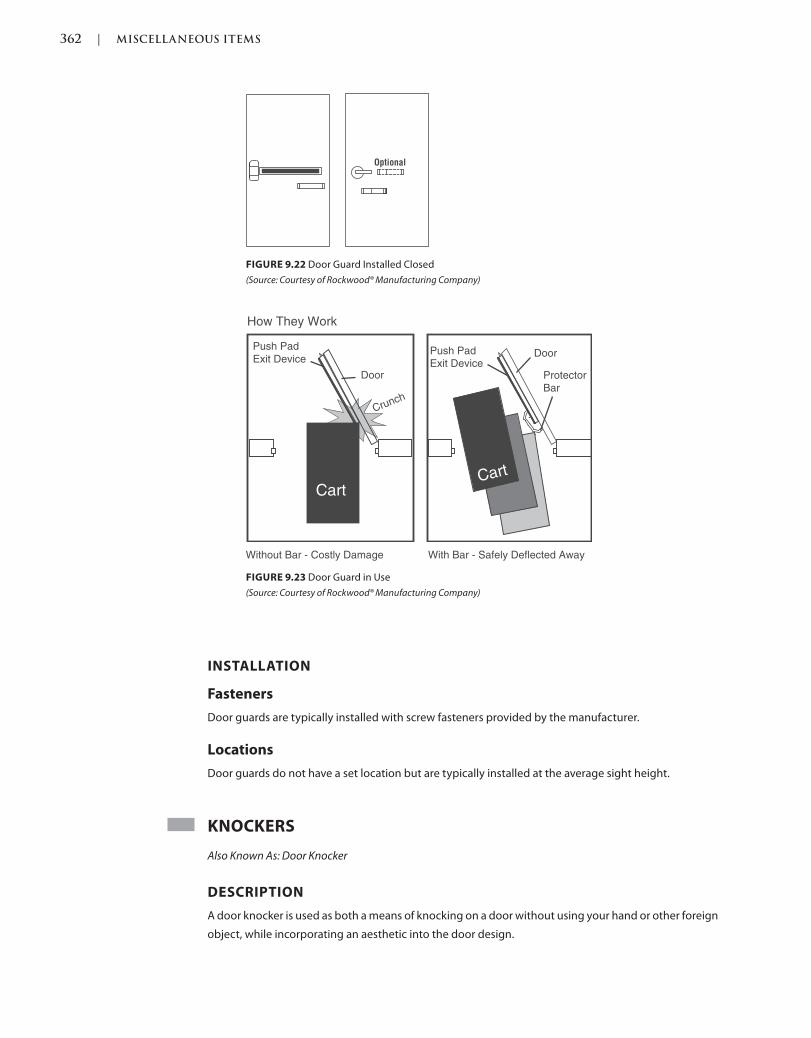
362 | MISCELLANEOUS ITEMS
c09.indd Page 362 03/03/2015 04:35:2:PM
INSTALLATION
Fasteners
Door guards are typically installed with screw fasteners provided by the manufacturer.
Locations
Door guards do not have a set location but are typically installed at the average sight height.
KNOCKERS
Also Known As: Door Knocker
DESCRIPTION
A door knocker is used as both a means of knocking on a door without using your hand or other foreign
object, while incorporating an aesthetic into the door design.
How They Work
Without Bar - Costly Damage With Bar - Safely Deflected Away
CartCart
Push Pad
Exit Device
Door
Push Pad Exit Device
Door
Protector
Bar
Crunch
FIGURE 9.23 Door Guard in Use
(Source: Courtesy of Rockwood® Manufacturing Company)
FIGURE 9.22 Door Guard Installed Closed
(Source: Courtesy of Rockwood® Manufacturing Company)

MISCELLANEOUS ITEMS | 363
c09.indd Page 363 03/03/2015 04:35:2:PM
PROPERTIES
Finishes
Depending on the manufacturer, door knockers are available in most architectural finishes to match
other installed hardware on the door such as the hinges and lockset.
Grades
Door knockers are not typically categorized in grades.
Materials
Door knockers are most typically manufactured from a brass but can also be manufactured from other
materials such as aluminum, bronze, steel, or stainless steel.
TYPES
There are various types of door knockers, typically distinguished by shape and size, but all with the
same intent: to knock on a door without having to use your hand or foreign object.
OPTIONS
There are typically not many options for door knockers other than the size, material, finish, fasteners,
and the addition of a door viewer. The door viewer is typically installed on a dwelling or hotel door so
that one can see who is on the other side of the door prior to opening the door to ensure as best as
possible one’s safety. By incorporating the viewer into the knocker, a separate preparation, installation,
and finished product are not necessary on the door as it is incorporated into one device instead of two
separate devices.
FIGURE 9.24 Door Knocker
(Source: Courtesy of Rockwood® Manufacturing Company)
FIGURE 9.25 Door Knocker
(Source: Courtesy of Rockwood® Manufacturing Company)
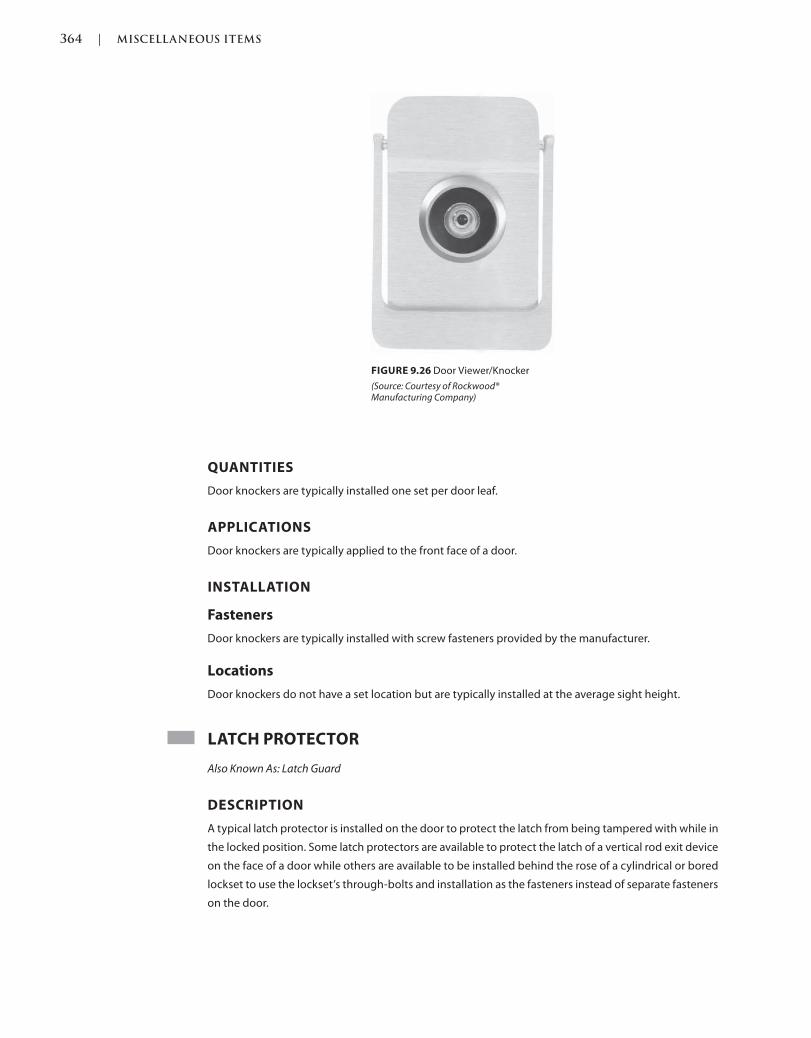
364 | MISCELLANEOUS ITEMS
c09.indd Page 364 03/03/2015 04:35:2:PM
QUANTITIES
Door knockers are typically installed one set per door leaf.
APPLICATIONS
Door knockers are typically applied to the front face of a door.
INSTALLATION
Fasteners
Door knockers are typically installed with screw fasteners provided by the manufacturer.
Locations
Door knockers do not have a set location but are typically installed at the average sight height.
LATCH PROTECTOR
Also Known As: Latch Guard
DESCRIPTION
A typical latch protector is installed on the door to protect the latch from being tampered with while in
the locked position. Some latch protectors are available to protect the latch of a vertical rod exit device
on the face of a door while others are available to be installed behind the rose of a cylindrical or bored
lockset to use the lockset’s through-bolts and installation as the fasteners instead of separate fasteners
on the door.
FIGURE 9.26 Door Viewer/Knocker
(Source: Courtesy of Rockwood® Manufacturing Company)
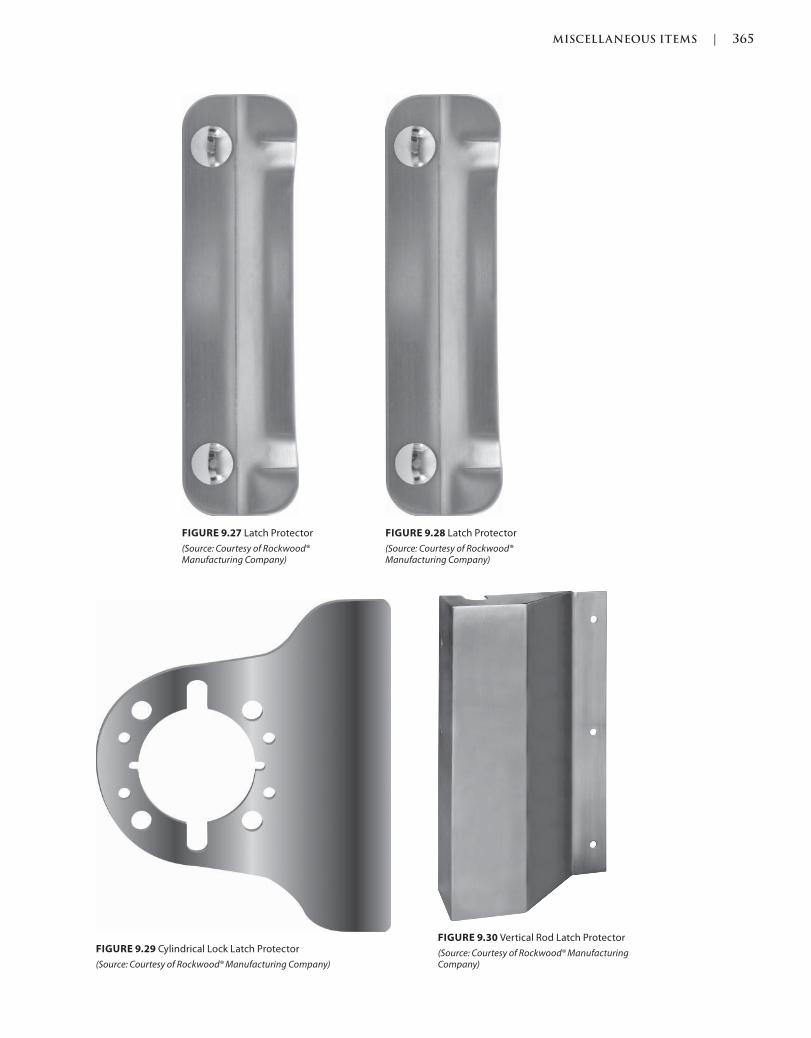
MISCELLANEOUS ITEMS | 365
c09.indd Page 365 03/03/2015 04:35:2:PM
FIGURE 9.27 Latch Protector
(Source: Courtesy of Rockwood® Manufacturing Company)
FIGURE 9.28 Latch Protector
(Source: Courtesy of Rockwood® Manufacturing Company)
FIGURE 9.30 Vertical Rod Latch Protector
(Source: Courtesy of Rockwood® Manufacturing Company)
FIGURE 9.29 Cylindrical Lock Latch Protector
(Source: Courtesy of Rockwood® Manufacturing Company)
366 | MISCELLANEOUS ITEMS
c09.indd Page 366 03/03/2015 04:35:2:PM
PROPERTIES
Finishes
Depending on the manufacturer, latch protectors are typically available in very limited architectural
finishes to match other installed hardware on the door such as the hinges and lockset.
Grades
Latch protectors are not typically categorized in grades.
Materials
Latch protectors are most typically manufactured from steel or stainless steel but can also be
manufactured from other materials such as aluminum, bronze, or brass.
TYPES
There are various types of latch protectors typically distinguished by various shapes and sizes, but all
with the same intent: to prevent the latch of a lockset from being accessed and tampered with for
unauthorized entry.
OPTIONS
There are typically not many options for latch guards other than the size, material, finish, type of device
and latch it is protecting, and fasteners.
QUANTITIES
Latch guards are typically installed one per door leaf.
APPLICATIONS
Latch guards are typically applied to the front face of the latch edge of a door.
INSTALLATION
Fasteners
Latch guards are typically installed with screw fasteners provided by the manufacturer but can also be
through-bolted, depending on the other hardware installed near or at the same location as the latch
guard.
Locations
Latch guards are typically installed centered over the locking device on the latch edge outside face of
a door.
LETTERBOX PLATES
Also Known As: Mail Slot
DESCRIPTION
Letterbox plates are also referred to as mail slots and are typically frames for a cutout in the face of a
door that is used to accept mail inside the home without having to open the door. Mail slots would be
MISCELLANEOUS ITEMS | 367
c09.indd Page 367 03/03/2015 04:35:2:PM
an alternative to a mail box and typically have a spring door that lifts up to expose the hole for mail
entry, and then the spring tension automatically closes the door over the hole to protect the interior
from weather or unwanted bugs or critters.
PROPERTIES
Finishes
Depending on the manufacturer, letter box plates are typically available in most architectural finishes
to match other installed hardware on the door such as the hinges and lockset.
Grades
Letter box plates are not typically categorized in grades.
Materials
Letter box plates are most typically manufactured from brass, bronze, steel, or stainless steel but can
also be manufactured from other materials such as aluminum.
TYPES
There are various types of letter box plates, typically distinguished by shape and size, but all with the
same intent: to be used in lieu of a mail box and to allow mail to be slipped into the home without
having to open the door.
OPTIONS
There are typically not many options for letter box plates other than the size, material, finish, and
fasteners. The only other option would be a sleeve that is installed on the inside of the door to direct
the mail to a certain location inside of the door such as a basket underneath or attached to the inside
face of the door.
QUANTITIES
Letter box plates are typically installed one per door leaf.
APPLICATIONS
Letter box plates are typically applied to both sides of the center face of a door toward the bottom,
sandwiching the door in between the frame plates.
INSTALLATION
Fasteners
Letter box plates are typically installed with screw fasteners provided by the manufacturer but can also
be through-bolted, depending on the other hardware installed near or at the same location such as the
latch guard.
Locations
Letter box plates are typically installed centered in the door toward the bottom half of the door but
they can be installed at the user’s preference.
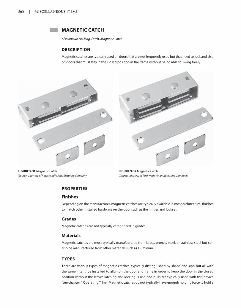
368 | MISCELLANEOUS ITEMS
c09.indd Page 368 03/03/2015 04:35:2:PM
MAGNETIC CATCH
Also known As: Mag Catch, Magnetic Latch
DESCRIPTION
Magnetic catches are typically used on doors that are not frequently used but that need to lock and also
on doors that must stay in the closed position in the frame without being able to swing freely.
FIGURE 9.32 Magnetic Catch
(Source: Courtesy of Rockwood® Manufacturing Company)
FIGURE 9.31 Magnetic Catch
(Source: Courtesy of Rockwood® Manufacturing Company)
PROPERTIES
Finishes
Depending on the manufacturer, magnetic catches are typically available in most architectural finishes
to match other installed hardware on the door such as the hinges and lockset.
Grades
Magnetic catches are not typically categorized in grades.
Materials
Magnetic catches are most typically manufactured from brass, bronze, steel, or stainless steel but can
also be manufactured from other materials such as aluminum.
TYPES
There are various types of magnetic catches, typically distinguished by shape and size, but all with
the same intent: be installed to align on the door and frame in order to keep the door in the closed
position without the leaves latching and locking. Push and pulls are typically used with this device
(see chapter 4 Operating Trim). Magnetic catches do not typically have enough holding force to hold a
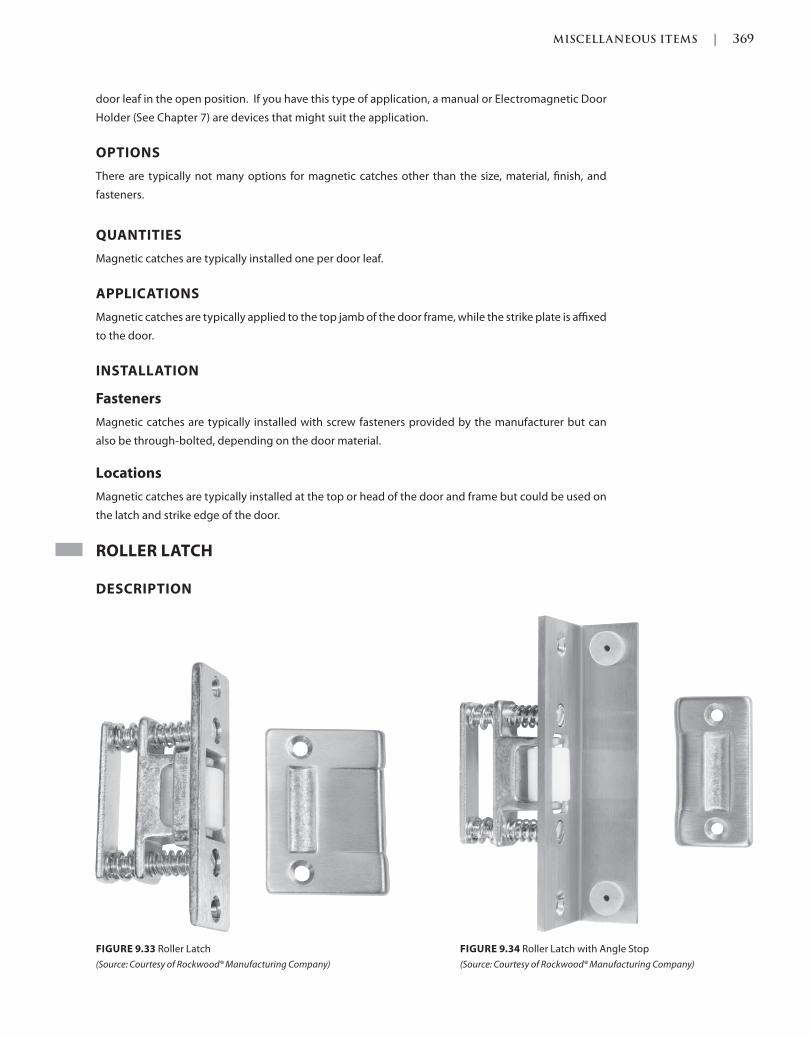
MISCELLANEOUS ITEMS | 369
c09.indd Page 369 03/03/2015 04:35:2:PM
door leaf in the open position. If you have this type of application, a manual or Electromagnetic Door
Holder (See Chapter 7) are devices that might suit the application.
OPTIONS
There are typically not many options for magnetic catches other than the size, material, finish, and
fasteners.
QUANTITIES
Magnetic catches are typically installed one per door leaf.
APPLICATIONS
Magnetic catches are typically applied to the top jamb of the door frame, while the strike plate is affixed
to the door.
INSTALLATION
Fasteners
Magnetic catches are typically installed with screw fasteners provided by the manufacturer but can
also be through-bolted, depending on the door material.
Locations
Magnetic catches are typically installed at the top or head of the door and frame but could be used on
the latch and strike edge of the door.
ROLLER LATCH
DESCRIPTION
FIGURE 9.34 Roller Latch with Angle Stop
(Source: Courtesy of Rockwood® Manufacturing Company)
FIGURE 9.33 Roller Latch
(Source: Courtesy of Rockwood® Manufacturing Company)
370 | MISCELLANEOUS ITEMS
c09.indd Page 370 03/03/2015 04:35:2:PM
PROPERTIES
Finishes
Depending on the manufacturer, roller latches are typically available in most architectural finishes to
match other installed hardware on the door such as the hinges and lockset.
Grades
Roller latches are not typically categorized in grades.
Materials
Roller latches are most typically manufactured from aluminum, but can also be manufactured from
other metal materials such as brass, bronze, steel, or stainless steel.
TYPES
There are various types of roller latches typically distinguished by various shapes and sizes, but all with
the same intent: to latch the door into the frame to secure it in place in the closed position.
OPTIONS
There are typically not many options for roller latches other than the size, material, finish, and fasteners.
QUANTITIES
Roller latches are typically installed one per door leaf.
APPLICATIONS
Roller latches are typically applied to both the top of the door and the strike plate on the head of the
door frame. This device can also be installed on the lock and strike side of the door and frame.
INSTALLATION
Fasteners
Roller latches are typically installed with screw fasteners provided by the manufacturer.
Locations
Roller latches are typically installed at the top of the door and frame, although they can be installed on
the strike and latch side of the door.
SIGNAGEROOM NAME PLATES AND NUMBERS
Also Known As: Signs, Room Names, Room Numbers, Room Signs
DESCRIPTION
Room name and number plate signage is used to provide room names and numbers for the public and
users to easily identify them, such as “Men’s,” “Women’s,” or “Room 232A.” Signs might also be used to
identify other room types such as those that the public should avoid such as “Janitor’s Closet” or “Boiler
Room.”
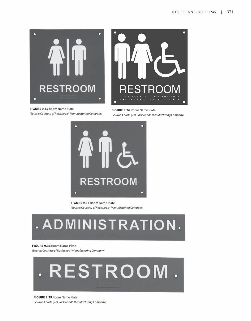
MISCELLANEOUS ITEMS | 371
c09.indd Page 371 03/03/2015 04:35:2:PM
FIGURE 9.35 Room Name Plate
(Source: Courtesy of Rockwood® Manufacturing Company)FIGURE 9.36 Room Name Plate
(Source: Courtesy of Rockwood® Manufacturing Company)
FIGURE 9.37 Room Name Plate
(Source: Courtesy of Rockwood® Manufacturing Company)
FIGURE 9.38 Room Name Plate
(Source: Courtesy of Rockwood® Manufacturing Company)
FIGURE 9.39 Room Name Plate
(Source: Courtesy of Rockwood® Manufacturing Company)
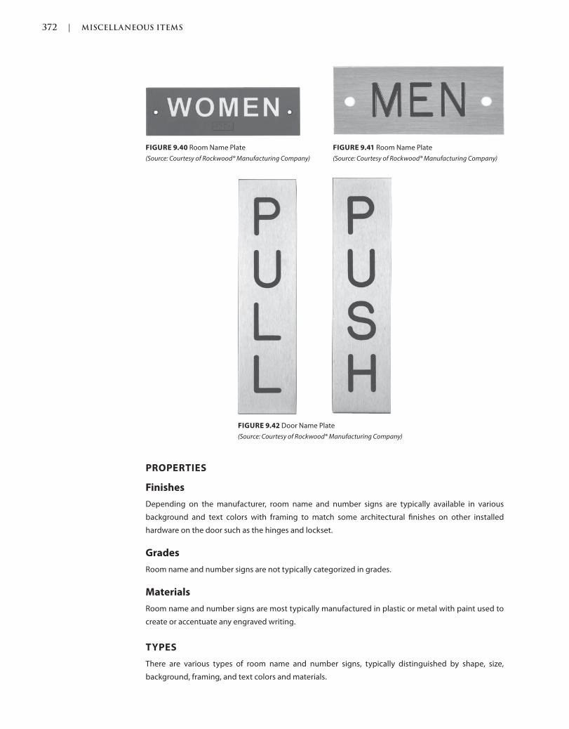
372 | MISCELLANEOUS ITEMS
c09.indd Page 372 03/03/2015 04:35:2:PM
PROPERTIES
Finishes
Depending on the manufacturer, room name and number signs are typically available in various
background and text colors with framing to match some architectural finishes on other installed
hardware on the door such as the hinges and lockset.
Grades
Room name and number signs are not typically categorized in grades.
Materials
Room name and number signs are most typically manufactured in plastic or metal with paint used to
create or accentuate any engraved writing.
TYPES
There are various types of room name and number signs, typically distinguished by shape, size,
background, framing, and text colors and materials.
FIGURE 9.42 Door Name Plate
(Source: Courtesy of Rockwood® Manufacturing Company)
FIGURE 9.41 Room Name Plate
(Source: Courtesy of Rockwood® Manufacturing Company)
FIGURE 9.40 Room Name Plate
(Source: Courtesy of Rockwood® Manufacturing Company)
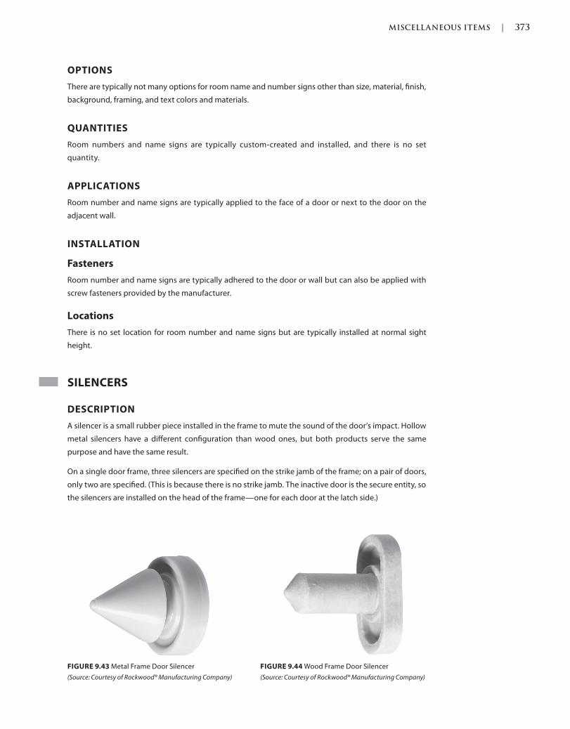
MISCELLANEOUS ITEMS | 373
c09.indd Page 373 03/03/2015 04:35:2:PM
OPTIONS
There are typically not many options for room name and number signs other than size, material, finish,
background, framing, and text colors and materials.
QUANTITIES
Room numbers and name signs are typically custom-created and installed, and there is no set
quantity.
APPLICATIONS
Room number and name signs are typically applied to the face of a door or next to the door on the
adjacent wall.
INSTALLATION
Fasteners
Room number and name signs are typically adhered to the door or wall but can also be applied with
screw fasteners provided by the manufacturer.
Locations
There is no set location for room number and name signs but are typically installed at normal sight
height.
SILENCERS
DESCRIPTION
A silencer is a small rubber piece installed in the frame to mute the sound of the door’s impact. Hollow
metal silencers have a different configuration than wood ones, but both products serve the same
purpose and have the same result.
On a single door frame, three silencers are specified on the strike jamb of the frame; on a pair of doors,
only two are specified. (This is because there is no strike jamb. The inactive door is the secure entity, so
the silencers are installed on the head of the frame—one for each door at the latch side.)
FIGURE 9.43 Metal Frame Door Silencer
(Source: Courtesy of Rockwood® Manufacturing Company)
FIGURE 9.44 Wood Frame Door Silencer
(Source: Courtesy of Rockwood® Manufacturing Company)

374 | MISCELLANEOUS ITEMS
c09.indd Page 374 03/03/2015 04:35:2:PM
PROPERTIES
Finishes
Silencers are typically available in gray but depending on the manufacturer might be available in other
colors such as black, white, or brown.
Grades
Silencers are not typically categorized in grades.
Materials
Silencers are most typically manufactured from a rubber material but can also be manufactured from
a plastic material.
TYPES
There are typically three types of silencers, those manufactured to be inserted into metal door frames,
those manufactured to be inserted into wood door frames, and those that are adhered to any material
door frame.
OPTIONS
There are typically no options for door silencers other than the type of application.
QUANTITIES
Silencers are typically installed three per single door leaf and two per pair of doors. Single doors have
three silencers installed along the latch edge of the frame, while pairs have one installed at the latch
edge of the head of each door leaf.
FIGURE 9.45 Single Metal Door Frame
Silencer Installed
(Source: Courtesy of Scott J. Tobias)
FIGURE 9.46 Pair Metal Door Frame Silencer Installed Close Up
(Source: Courtesy of Scott J. Tobias)

MISCELLANEOUS ITEMS | 375
c09.indd Page 375 03/03/2015 04:35:2:PM
APPLICATIONS
Silencers are typically applied to the latch edge of a single door and the latch edge head of both leaves
of a pair of doors.
INSTALLATION
Fasteners
Silencers do not typically require fasteners, as they are inserted into preparation holes in the door
frame unless they are adhesive silencers that stick to the door frame instead of being inserted in them.
Adhesive silencers might be required at the last minute during installation if the door frame supplier
did not order the frames prepared to accept the conventional silencers.
Locations
Silencers are typically installed at equal locations on the door frame as determined by the manufacturer
of the door frame.
FIGURE 9.47 Pair Metal Door Frame Silencer Installed
(Source: Courtesy of Scott J. Tobias)
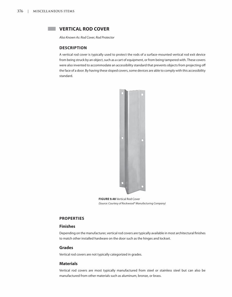
376 | MISCELLANEOUS ITEMS
c09.indd Page 376 03/03/2015 04:35:2:PM
VERTICAL ROD COVER
Also Known As: Rod Cover, Rod Protector
DESCRIPTION
A vertical rod cover is typically used to protect the rods of a surface-mounted vertical rod exit device
from being struck by an object, such as a cart of equipment, or from being tampered with. These covers
were also invented to accommodate an accessibility standard that prevents objects from projecting off
the face of a door. By having these sloped covers, some devices are able to comply with this accessibility
standard.
FIGURE 9.48 Vertical Rod Cover
(Source: Courtesy of Rockwood® Manufacturing Company)
PROPERTIES
Finishes
Depending on the manufacturer, vertical rod covers are typically available in most architectural finishes
to match other installed hardware on the door such as the hinges and lockset.
Grades
Vertical rod covers are not typically categorized in grades.
Materials
Vertical rod covers are most typically manufactured from steel or stainless steel but can also be
manufactured from other materials such as aluminum, bronze, or brass.
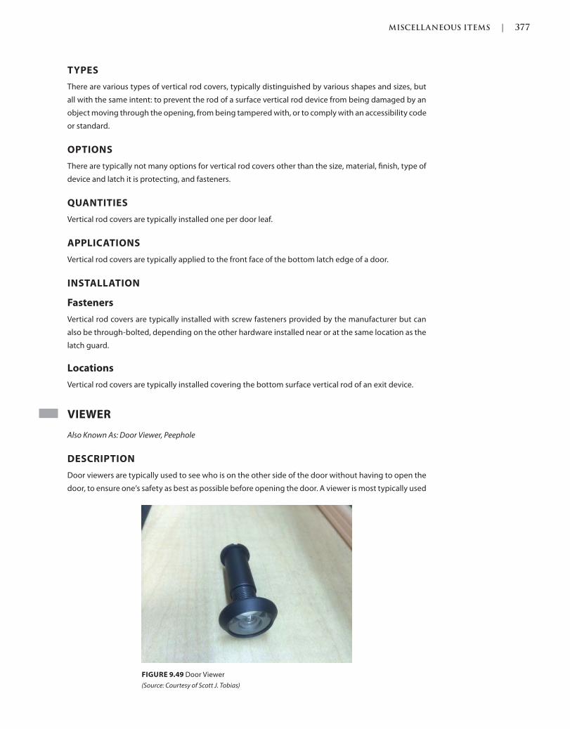
MISCELLANEOUS ITEMS | 377
c09.indd Page 377 03/03/2015 04:35:2:PM
TYPES
There are various types of vertical rod covers, typically distinguished by various shapes and sizes, but
all with the same intent: to prevent the rod of a surface vertical rod device from being damaged by an
object moving through the opening, from being tampered with, or to comply with an accessibility code
or standard.
OPTIONS
There are typically not many options for vertical rod covers other than the size, material, finish, type of
device and latch it is protecting, and fasteners.
QUANTITIES
Vertical rod covers are typically installed one per door leaf.
APPLICATIONS
Vertical rod covers are typically applied to the front face of the bottom latch edge of a door.
INSTALLATION
Fasteners
Vertical rod covers are typically installed with screw fasteners provided by the manufacturer but can
also be through-bolted, depending on the other hardware installed near or at the same location as the
latch guard.
Locations
Vertical rod covers are typically installed covering the bottom surface vertical rod of an exit device.
VIEWER
Also Known As: Door Viewer, Peephole
DESCRIPTION
Door viewers are typically used to see who is on the other side of the door without having to open the
door, to ensure one’s safety as best as possible before opening the door. A viewer is most typically used
FIGURE 9.49 Door Viewer
(Source: Courtesy of Scott J. Tobias)
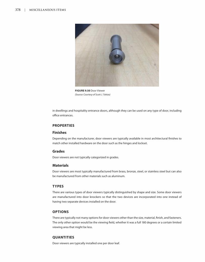
378 | MISCELLANEOUS ITEMS
c09.indd Page 378 03/03/2015 04:35:2:PM
in dwellings and hospitality entrance doors, although they can be used on any type of door, including
office entrances.
PROPERTIES
Finishes
Depending on the manufacturer, door viewers are typically available in most architectural finishes to
match other installed hardware on the door such as the hinges and lockset.
Grades
Door viewers are not typically categorized in grades.
Materials
Door viewers are most typically manufactured from brass, bronze, steel, or stainless steel but can also
be manufactured from other materials such as aluminum.
TYPES
There are various types of door viewers typically distinguished by shape and size. Some door viewers
are manufactured into door knockers so that the two devices are incorporated into one instead of
having two separate devices installed on the door.
OPTIONS
There are typically not many options for door viewers other than the size, material, finish, and fasteners.
The only other option would be the viewing field, whether it was a full 180 degrees or a certain limited
viewing area that might be less.
QUANTITIES
Door viewers are typically installed one per door leaf.
FIGURE 9.50 Door Viewer
(Source: Courtesy of Scott J. Tobias)
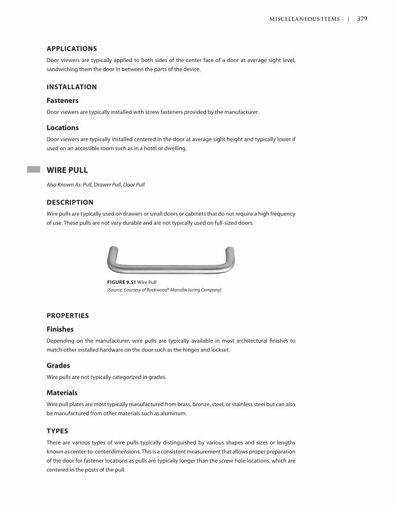
MISCELLANEOUS ITEMS | 379
c09.indd Page 379 03/03/2015 04:35:2:PM
APPLICATIONS
Door viewers are typically applied to both sides of the center face of a door at average sight level,
sandwiching them the door in between the parts of the device.
INSTALLATION
Fasteners
Door viewers are typically installed with screw fasteners provided by the manufacturer.
Locations
Door viewers are typically installed centered in the door at average sight height and typically lower if
used on an accessible room such as in a hotel or dwelling.
WIRE PULL
Also Known As: Pull, Drawer Pull, Door Pull
DESCRIPTION
Wire pulls are typically used on drawers or small doors or cabinets that do not require a high frequency
of use. These pulls are not very durable and are not typically used on full-sized doors.
FIGURE 9.51 Wire Pull
(Source: Courtesy of Rockwood® Manufacturing Company)
PROPERTIES
Finishes
Depending on the manufacturer, wire pulls are typically available in most architectural finishes to
match other installed hardware on the door such as the hinges and lockset.
Grades
Wire pulls are not typically categorized in grades.
Materials
Wire pull plates are most typically manufactured from brass, bronze, steel, or stainless steel but can also
be manufactured from other materials such as aluminum.
TYPES
There are various types of wire pulls typically distinguished by various shapes and sizes or lengths
known as center-to-center dimensions. This is a consistent measurement that allows proper preparation
of the door for fastener locations as pulls are typically longer than the screw hole locations, which are
centered in the posts of the pull.
380 | MISCELLANEOUS ITEMS
c09.indd Page 380 03/03/2015 04:35:2:PM
OPTIONS
There are typically not many options for wire pulls other than the size/center-to-center dimension,
material, finish, and fasteners.
QUANTITIES
Wire pulls are typically installed one per door leaf, although they might be installed back to back where
they are at the same exact location on both sides of the door and typically connected by the same
fastener, utilizing set screws for the concealed installation.
APPLICATIONS
Wire pulls are typically applied to one side of the door with screws holding it from behind, although
back-to-back applications might be desired if the door is operated from both sides of the opening.
INSTALLATION
Fasteners
Wire pulls are typically installed with screw fasteners provided by the manufacturer.
Locations
Wire pulls might be treated as door pulls and in that case should be installed at locations as
recommended by industry standards and codes, depending on the door type, which are typically
measured from the finished floor.
CUSTOM STEEL DOORS AND FRAMES
Custom steel doors and frames are recommended to have the centerline of a door pull installed at 42
inches above the finished floor.
FLUSH WOOD DOORS AND FRAMES
Flush wood doors and frames are recommended to have the centerline of a door pull installed at 42
inches above the finished floor.
STANDARD STEEL DOORS AND FRAMES
Standard steel doors and frames are recommended to have the centerline of a door pull installed at 42
inches above the finished floor.
SMOKE AND FIRE DETECTION DEVICES
Any items not listed in Chapter 5 or any other previous chapters should be listed at this point in any
hardware schedule or specification.
REFERENCES
Codes and standards are available to set the minimum requirements of door openings, (see the
Introduction of this book for more information). Some jurisdictions have specific codes and standards,
which were either modified from another existing code or created for their own use.
Language and section numbers can change slightly or drastically when the codes are updated. Look for
an outline, if available, of the changes that took place in the respective update.
MISCELLANEOUS ITEMS | 381
c09.indd Page 381 03/03/2015 04:35:2:PM
CODES
International Building Code (IBC)
The following are chapters of a modified or fully adopted version of the International Building Code,
which refer to miscellaneous items or door hardware in general:
Chapter 7: Fire and Smoke Protection Features
Chapter 10: Means of Egress
Chapter 17: Special Inspections and Tests
National Fire Protection Association (NFPA) 101: Life Safety Code
The following is a chapter of a modified or fully adopted version of the NFPA 101: Life Safety Code,
which refers to miscellaneous items or door hardware in general:
Chapter 7: Means of Egress
STANDARDS
ADA Accessibility Guidelines for Buildings and Facilities (ADAAG)
The following is a chapter of a modified or fully adopted version of the ADA Accessibility Guidelines for
Buildings and Facilities, which refers to miscellaneous items or door hardware in general:
Chapter 4: Accessible Routes
ASTM International (ASTM)
There are hundreds of ASTM International testing standards that are related to doors and door
hardware, from material and assembly testing to installation and application testing.
Door and Hardware Institute (DHI)
The following are technical documents available for reference that refer to miscellaneous items or door
hardware in general:
Abbreviations and Symbols
Basic Architectural Hardware
Hardware for Healthcare Facilities
Installation Guide for Doors and Hardware
Processing Hardware for Custom Aluminum Entrances
Recommended Locations for Builders Hardware Custom Steel Doors & Frames
Recommended Locations for Architectural Hardware for Standard Steel Doors & Frames
Recommended Locations for Architectural Hardware for Flush Wood Doors
Recommended Procedures for Processing Hardware Schedules and Templates
Sequence and Format for the Hardware Schedule
Tech-Talk ASD-1 Aluminum Storefront Doors
Tech Talk PH-1 Protective Hardware
International Code Council A117.1 Accessible and Usable Buildings and
Facilities (ICC)
The following is a chapter of a modified or fully adopted version of the ICC A117.1 Accessible and Usable
Buildings and Facilities, which refers to miscellaneous items or door hardware in general:
Chapter 4: Accessible Routes
382 | MISCELLANEOUS ITEMS
c09.indd Page 382 03/03/2015 04:35:2:PM
National Fire Protection Association (NFPA)
The following are chapters of a modified or fully adopted version of NFPA 80: Standard for Fire Doors
and Other Opening Protectives, which refer to miscellaneous items or door hardware in general:
Chapter 5: Care and Maintenance
Chapter 6: Swinging Doors with Builders Hardware
Chapter 7: Swinging Doors with Fire Door Hardware
Chapter 8: Horizontally Sliding Doors
Chapter 9: Special-Purpose Horizontally Sliding Accordion or Folding Doors
Chapter 16: Access Doors
Chapter 19: Installation, Testing, and Maintenance of Fire Dampers
Annex A: Explanatory Material
The following is a chapter of a modified or fully adopted version of NFPA 105: Standard for Smoke Door
Assemblies and Other Opening Protectives, which refers to miscellaneous items or door hardware in
general:
Chapter 6: Installation, Testing, and Maintenance of Smoke Dampers
The following is a chapter of a modified or fully adopted version of NFPA 252: Standard Method of Fire
Tests of Door Assemblies, which refers to miscellaneous items or door hardware in general:
Chapter 5: Fire Door Assembly
Annex B: Commentary
American National Standards Institute/Builders Hardware Manufacturers
Association (ANSI/BHMA)
The following are standards that refer to miscellaneous items or door hardware in general:
ANSI/BHMA A156.6 American National Standard for Architectural Door Trim
ANSI/BHMA A156.16 American National Standard for Auxiliary Hardware
ANSI/BHMA A156.18 American National Standard for Materials and Finishes

383
c10.indd 03/03/2015 04:6:22:PM Page 383Trim: 215 x 276 mm
Miscellaneous Items
COMPUTERS
Also Known As: Personal Computers, PCs, Computers, Laptops
DESCRIPTION
Computers might be necessary to run software to operate the electronic door hardware and integrate
into any other systems such as fire or burglar alarm monitoring systems. Some door hardware
manufacturers require the use of their own software to operate the system, which means that the
devices all have to come from the same manufacturer, while others allow open compatibility, also
known as open architecture, which allows a multitude of devices and software to talk to each other and
operate together in the same environment regardless of who the manufacturer is.
There are many properties, types, options, quantities, applications, and installations offered by various
manufacturers, and each system should be designed by an experienced professional specific to each
client and the users of the system.
DRAWINGS AND DIAGRAMS
Also Known As: Elevation Drawings or Diagrams, Point-to-Point Drawings or Diagrams, Wiring Drawings or
Diagrams, Point-to-Points, Elevations
Drawings and diagrams should be required at minimum for each electrified door opening, no matter
how little or how much or how few or how many electrification or devices are being used. These
drawings and diagrams should be specified in the project specifications but are not necessarily part of
the specifications.
10
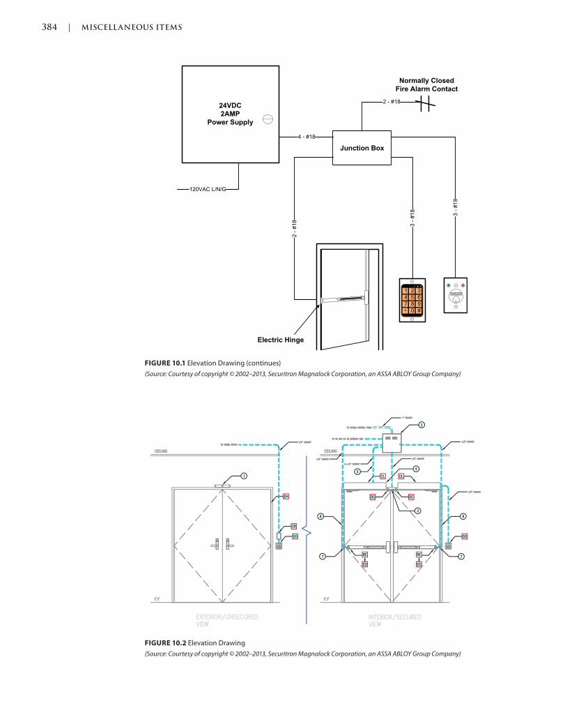
384 | MISCELLANEOUS ITEMS
Trim: 215 x 276 mm c10.indd 03/03/2015 04:6:22:PM Page 384
FIGURE 10.1 Elevation Drawing (continues)
(Source: Courtesy of copyright © 2002–2013, Securitron Magnalock Corporation, an ASSA ABLOY Group Company)
FIGURE 10.2 Elevation Drawing
(Source: Courtesy of copyright © 2002–2013, Securitron Magnalock Corporation, an ASSA ABLOY Group Company)
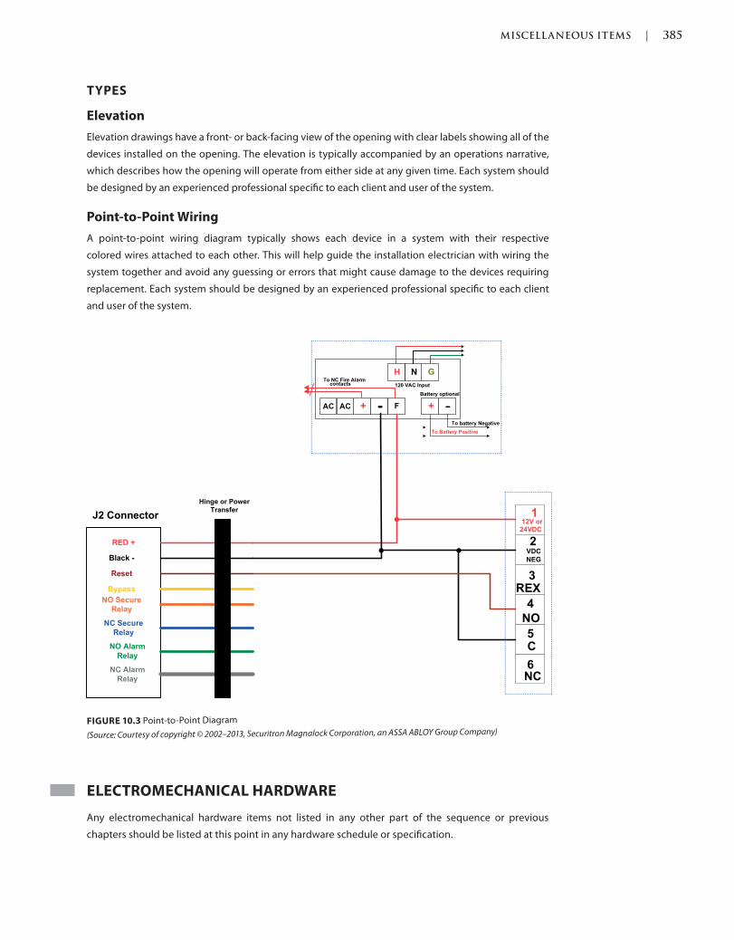
MISCELLANEOUS ITEMS | 385
c10.indd 03/03/2015 04:6:22:PM Page 385Trim: 215 x 276 mm
FIGURE 10.3 Point-to-Point Diagram
(Source: Courtesy of copyright © 2002–2013, Securitron Magnalock Corporation, an ASSA ABLOY Group Company)
TYPES
Elevation
Elevation drawings have a front- or back-facing view of the opening with clear labels showing all of the
devices installed on the opening. The elevation is typically accompanied by an operations narrative,
which describes how the opening will operate from either side at any given time. Each system should
be designed by an experienced professional specific to each client and user of the system.
Point-to-Point Wiring
A point-to-point wiring diagram typically shows each device in a system with their respective
colored wires attached to each other. This will help guide the installation electrician with wiring the
system together and avoid any guessing or errors that might cause damage to the devices requiring
replacement. Each system should be designed by an experienced professional specific to each client
and user of the system.
ELECTROMECHANICAL HARDWARE
Any electromechanical hardware items not listed in any other part of the sequence or previous
chapters should be listed at this point in any hardware schedule or specification.
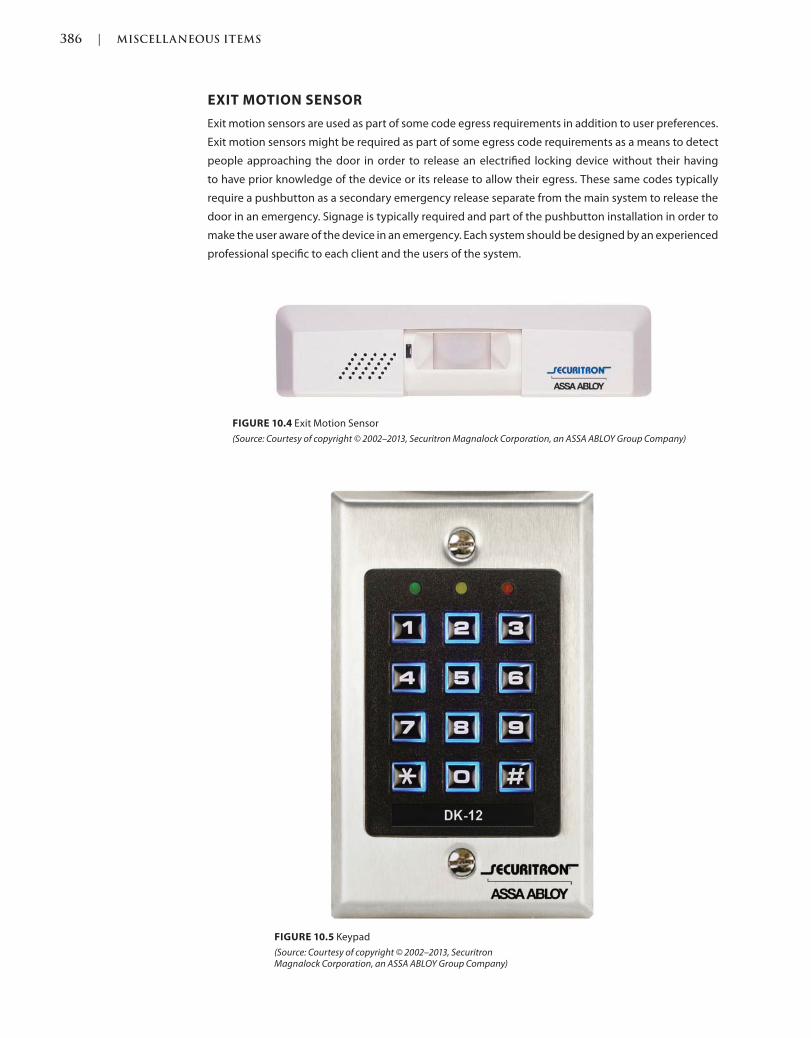
386 | MISCELLANEOUS ITEMS
Trim: 215 x 276 mm c10.indd 03/03/2015 04:6:22:PM Page 386
FIGURE 10.4 Exit Motion Sensor
(Source: Courtesy of copyright © 2002–2013, Securitron Magnalock Corporation, an ASSA ABLOY Group Company)
FIGURE 10.5 Keypad
(Source: Courtesy of copyright © 2002–2013, Securitron Magnalock Corporation, an ASSA ABLOY Group Company)
EXIT MOTION SENSOR
Exit motion sensors are used as part of some code egress requirements in addition to user preferences.
Exit motion sensors might be required as part of some egress code requirements as a means to detect
people approaching the door in order to release an electrified locking device without their having
to have prior knowledge of the device or its release to allow their egress. These same codes typically
require a pushbutton as a secondary emergency release separate from the main system to release the
door in an emergency. Signage is typically required and part of the pushbutton installation in order to
make the user aware of the device in an emergency. Each system should be designed by an experienced
professional specific to each client and the users of the system.
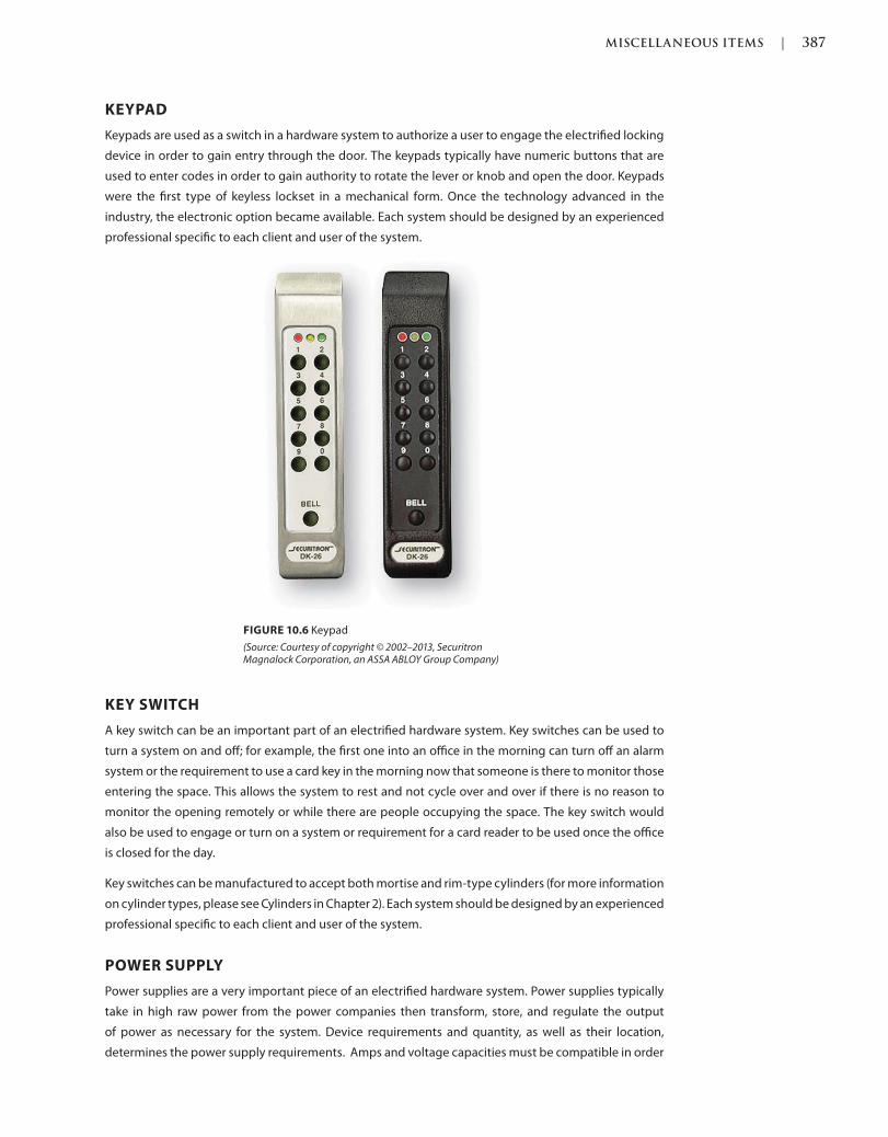
MISCELLANEOUS ITEMS | 387
c10.indd 03/03/2015 04:6:22:PM Page 387Trim: 215 x 276 mm
FIGURE 10.6 Keypad
(Source: Courtesy of copyright © 2002–2013, Securitron Magnalock Corporation, an ASSA ABLOY Group Company)
KEYPAD
Keypads are used as a switch in a hardware system to authorize a user to engage the electrified locking
device in order to gain entry through the door. The keypads typically have numeric buttons that are
used to enter codes in order to gain authority to rotate the lever or knob and open the door. Keypads
were the first type of keyless lockset in a mechanical form. Once the technology advanced in the
industry, the electronic option became available. Each system should be designed by an experienced
professional specific to each client and user of the system.
KEY SWITCH
A key switch can be an important part of an electrified hardware system. Key switches can be used to
turn a system on and off; for example, the first one into an office in the morning can turn off an alarm
system or the requirement to use a card key in the morning now that someone is there to monitor those
entering the space. This allows the system to rest and not cycle over and over if there is no reason to
monitor the opening remotely or while there are people occupying the space. The key switch would
also be used to engage or turn on a system or requirement for a card reader to be used once the office
is closed for the day.
Key switches can be manufactured to accept both mortise and rim-type cylinders (for more information
on cylinder types, please see Cylinders in Chapter 2). Each system should be designed by an experienced
professional specific to each client and user of the system.
POWER SUPPLY
Power supplies are a very important piece of an electrified hardware system. Power supplies typically
take in high raw power from the power companies then transform, store, and regulate the output
of power as necessary for the system. Device requirements and quantity, as well as their location,
determines the power supply requirements. Amps and voltage capacities must be compatible in order
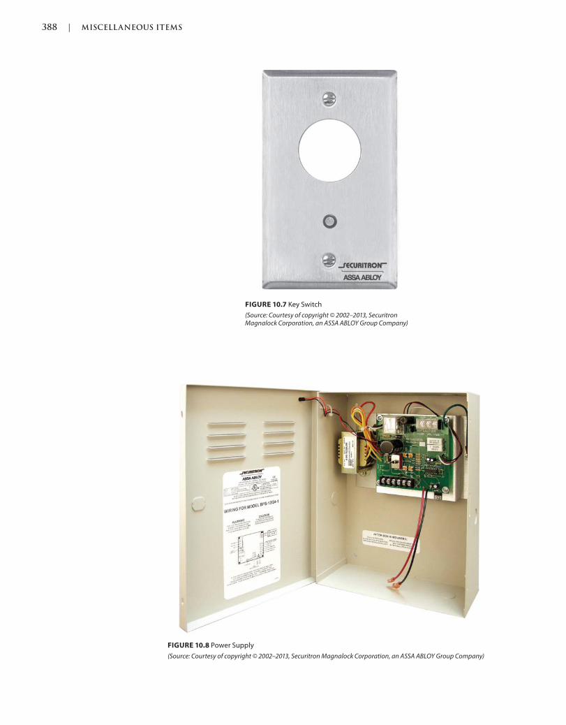
388 | MISCELLANEOUS ITEMS
Trim: 215 x 276 mm c10.indd 03/03/2015 04:6:22:PM Page 388
FIGURE 10.7 Key Switch
(Source: Courtesy of copyright © 2002–2013, Securitron Magnalock Corporation, an ASSA ABLOY Group Company)
FIGURE 10.8 Power Supply
(Source: Courtesy of copyright © 2002–2013, Securitron Magnalock Corporation, an ASSA ABLOY Group Company)
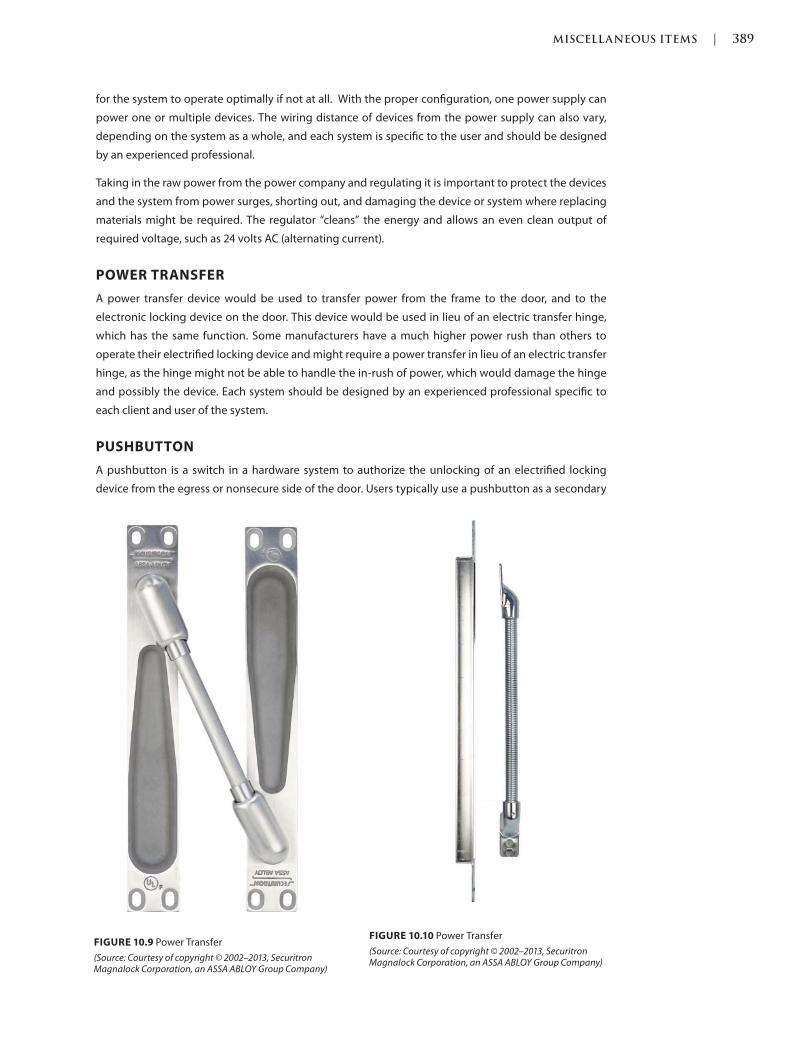
MISCELLANEOUS ITEMS | 389
c10.indd 03/03/2015 04:6:22:PM Page 389Trim: 215 x 276 mm
for the system to operate optimally if not at all. With the proper configuration, one power supply can
power one or multiple devices. The wiring distance of devices from the power supply can also vary,
depending on the system as a whole, and each system is specific to the user and should be designed
by an experienced professional.
Taking in the raw power from the power company and regulating it is important to protect the devices
and the system from power surges, shorting out, and damaging the device or system where replacing
materials might be required. The regulator “cleans” the energy and allows an even clean output of
required voltage, such as 24 volts AC (alternating current).
POWER TRANSFER
A power transfer device would be used to transfer power from the frame to the door, and to the
electronic locking device on the door. This device would be used in lieu of an electric transfer hinge,
which has the same function. Some manufacturers have a much higher power rush than others to
operate their electrified locking device and might require a power transfer in lieu of an electric transfer
hinge, as the hinge might not be able to handle the in-rush of power, which would damage the hinge
and possibly the device. Each system should be designed by an experienced professional specific to
each client and user of the system.
PUSHBUTTON
A pushbutton is a switch in a hardware system to authorize the unlocking of an electrified locking
device from the egress or nonsecure side of the door. Users typically use a pushbutton as a secondary
FIGURE 10.9 Power Transfer
(Source: Courtesy of copyright © 2002–2013, Securitron Magnalock Corporation, an ASSA ABLOY Group Company)
FIGURE 10.10 Power Transfer
(Source: Courtesy of copyright © 2002–2013, Securitron Magnalock Corporation, an ASSA ABLOY Group Company)
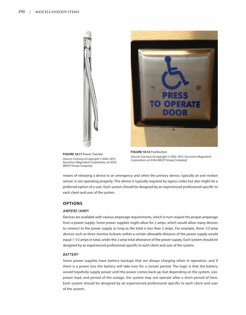
390 | MISCELLANEOUS ITEMS
Trim: 215 x 276 mm c10.indd 03/03/2015 04:6:22:PM Page 390
means of releasing a device in an emergency and when the primary device, typically an exit motion
sensor, is not operating properly. This device is typically required by egress codes but also might be a
preferred option of a user. Each system should be designed by an experienced professional specific to
each client and user of the system.
OPTIONS
AMPERE AMP
Devices are available with various amperage requirements, which in turn require the proper amperage
from a power supply. Some power supplies might allow for 2 amps, which would allow many devices
to connect to the power supply as long as the total is less than 2 amps. For example, three 1/2-amp
devices such as three mortise locksets within a certain allowable distance of the power supply would
equal 1 1/2 amps in total, under the 2-amp total allowance of the power supply. Each system should be
designed by an experienced professional specific to each client and user of the system.
BATTERY
Some power supplies have battery backups that are always charging when in operation, and if
there is a power loss the battery will take over for a certain period. The logic is that the battery
would hopefully supply power until the power comes back up, but depending on the system, size,
power load, and period of the outage, the system may not operate after a short period of time.
Each system should be designed by an experienced professional specific to each client and user
of the system.
FIGURE 10.12 Pushbutton
(Source: Courtesy of copyright © 2002–2013, Securitron Magnalock Corporation, an ASSA ABLOY Group Company)
FIGURE 10.11 Power Transfer
(Source: Courtesy of copyright © 2002–2013, Securitron Magnalock Corporation, an ASSA ABLOY Group Company)
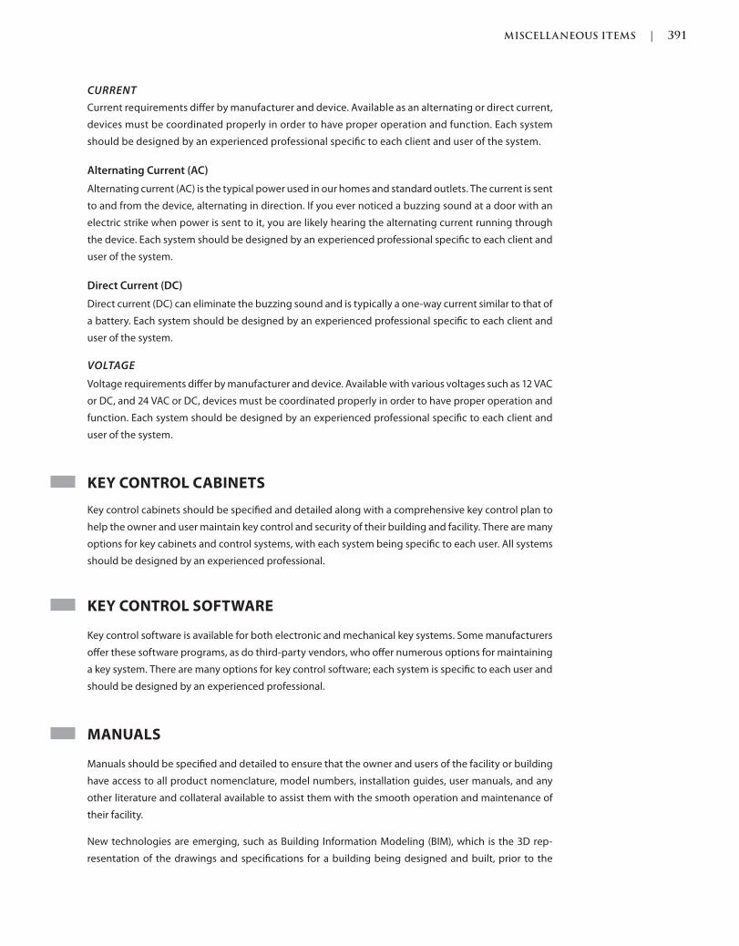
MISCELLANEOUS ITEMS | 391
c10.indd 03/03/2015 04:6:22:PM Page 391Trim: 215 x 276 mm
CURRENT
Current requirements differ by manufacturer and device. Available as an alternating or direct current,
devices must be coordinated properly in order to have proper operation and function. Each system
should be designed by an experienced professional specific to each client and user of the system.
Alternating Current (AC)
Alternating current (AC) is the typical power used in our homes and standard outlets. The current is sent
to and from the device, alternating in direction. If you ever noticed a buzzing sound at a door with an
electric strike when power is sent to it, you are likely hearing the alternating current running through
the device. Each system should be designed by an experienced professional specific to each client and
user of the system.
Direct Current (DC)
Direct current (DC) can eliminate the buzzing sound and is typically a one-way current similar to that of
a battery. Each system should be designed by an experienced professional specific to each client and
user of the system.
VOLTAGE
Voltage requirements differ by manufacturer and device. Available with various voltages such as 12 VAC
or DC, and 24 VAC or DC, devices must be coordinated properly in order to have proper operation and
function. Each system should be designed by an experienced professional specific to each client and
user of the system.
KEY CONTROL CABINETS
Key control cabinets should be specified and detailed along with a comprehensive key control plan to
help the owner and user maintain key control and security of their building and facility. There are many
options for key cabinets and control systems, with each system being specific to each user. All systems
should be designed by an experienced professional.
KEY CONTROL SOFTWARE
Key control software is available for both electronic and mechanical key systems. Some manufacturers
offer these software programs, as do third-party vendors, who offer numerous options for maintaining
a key system. There are many options for key control software; each system is specific to each user and
should be designed by an experienced professional.
MANUALS
Manuals should be specified and detailed to ensure that the owner and users of the facility or building
have access to all product nomenclature, model numbers, installation guides, user manuals, and any
other literature and collateral available to assist them with the smooth operation and maintenance of
their facility.
New technologies are emerging, such as Building Information Modeling (BIM), which is the 3D rep-
resentation of the drawings and specifications for a building being designed and built, prior to the
392 | MISCELLANEOUS ITEMS
Trim: 215 x 276 mm c10.indd 03/03/2015 04:6:22:PM Page 392
physical construction of the building. This new technology allows all “manuals” to be virtual and stored
in a computer file rather than hardcopy binders as traditionally done. This technology allows for the
troubleshooting, conflict resolution, accurate costing, timing, and coordination of all aspects of the
construction project prior to its taking place in order to be more efficient and better prepared for the
real thing.
Each system should be designed by an experienced professional specific to each client and user of the
system.
WIRE
Wire is typically specified by the electrician but should be coordinated in the specifications and
submittals for clarification of the wiring requirements and the party responsible for furnishing it.
Some of the important aspects of wiring are the distance a wire can run from the power supply
to the device. The wire gauge also plays an important part of the system design. The higher the
gauge, the longer a distance the power will travel without dissipating. If the gauge is too small,
and the distance is too long, the power will not operate the device properly, possibly preventing
the system from operating optimally, causing damage to the devices or system or, more seriously
loss, theft, or harm to the users of the building or facility. Wiring is an important part of the elec-
trified hardware system and each system is specific to each user and should be designed by an
experienced professional.
REFERENCES
Codes and standards are available to set the minimum requirements of door openings (see the
Introduction of this book for more information). Some jurisdictions have specific codes and standards,
which were either modified from another existing code or created for their own use.
Language and section numbers can change slightly or drastically when the codes are updated. Look for
an outline, if available, of the changes that took place in the respective update.
CODES
International Building Code (IBC)
The following are chapters of a modified or fully adopted version of the International Building Code,
2012 that refer to miscellaneous items or door hardware in general:
Chapter 7: Fire and Smoke Protection Features
Chapter 10: Means of Egress
4
Chapter 17: Special Inspections and Tests
National Fire Protection Association (NFPA) 101: Life Safety Code
The following is a chapter of a modified or fully adopted version of the NFPA 101: Life Safety Code that
refers to miscellaneous items or door hardware in general:
Chapter 7: Means of Egress
MISCELLANEOUS ITEMS | 393
c10.indd 03/03/2015 04:6:22:PM Page 393Trim: 215 x 276 mm
STANDARDS
ADA Accessibility Guidelines for Buildings and Facilities (ADAAG)
The following is a chapter of a modified or fully adopted version of the ADA Accessibility Guidelines for
Buildings and Facilities that refers to miscellaneous items or door hardware in general:
Chapter 4: Accessible Routes
ASTM International (ASTM)
There are hundreds of ASTM International testing standards that are related to doors and door
hardware, from material and assembly testing to installation and application testing.
Door and Hardware Institute (DHI)
The following are technical documents available for reference that refer to miscellaneous items or door
hardware in general:
Abbreviations and Symbols
Basic Architectural Hardware
Hardware for Healthcare Facilities
Installation Guide for Doors and Hardware
Processing Hardware for Custom Aluminum Entrances
Recommended Locations for Builders Hardware Custom Steel Doors & Frames
Recommended Locations for Architectural Hardware for Standard Steel Doors & Frames
Recommended Locations for Architectural Hardware for Flush Wood Doors
Recommended Procedures for Processing Hardware Schedules and Templates
Sequence and Format for the Hardware Schedule
Tech-Talk ASD-1 Aluminum Storefront Doors
Tech-Talk EAH-91 Electrified Architectural Hardware
International Code Council A117.1 Accessible and Usable Buildings and
Facilities, (ICC)
The following is a chapter of a modified or fully adopted version of the ICC A117.1 Accessible and Usable
Buildings and Facilities that refers to miscellaneous items or door hardware in general:
Chapter 4: Accessible Routes
National Fire Protection Association (NFPA)
The following are chapters of a modified or fully adopted version of NFPA 80: Standard for Fire Doors
and Other Opening Protectives that refer to miscellaneous items or door hardware in general:
Chapter 5: Care and Maintenance
Chapter 6: Swinging Doors with Builders Hardware
Chapter 7: Swinging Doors with Fire Door Hardware
Chapter 8: Horizontally Sliding Doors
Chapter 9: Special-Purpose Horizontally Sliding Accordion or Folding Doors
Chapter 16: Access Doors
Chapter 19: Installation, Testing, and Maintenance of Fire Dampers
Annex A: Explanatory Material
394 | MISCELLANEOUS ITEMS
Trim: 215 x 276 mm c10.indd 03/03/2015 04:6:22:PM Page 394
The following is a chapter of a modified or fully adopted version of NFPA 105: Standard for Smoke Door
Assemblies and Other Opening Protectives that refers to miscellaneous items or door hardware in
general:
Chapter 6: Installation, Testing, and Maintenance of Smoke Dampers
The following is a chapter of a modified or fully adopted version of NFPA 252: Standard Method of Fire
Tests of Door Assemblies that refers to miscellaneous items or door hardware in general:
Chapter 5: Fire Door Assembly
Annex B: Commentary
American National Standards Institute/Builders Hardware Manufacturers
Association (ANSI/BHMA)
The following are standards that refer to miscellaneous items or door hardware in general:
ANSI/BHMA A156.11 American National Standard for Cabinet Locks
ANSI/BHMA A156.18 American National Standard for Materials and Finishes
ANSI/BHMA A156.24 American National Standard for Delayed Egress Locking Systems
ANSI/BHMA A156.25 American National Standard for Electrified Locking Devices

bindex.indd 02/27/2015 05:24:42:PM Page 395Trim: 215 x 276 mm
Index
A
Abbreviations and Symbols (DHI), 82, 222, 240, 250, 280,
309, 327, 349, 381, 395
Abrasive coatings:
on latchsets and locksets, 212
on panic and fire exit trim, 143
on two- and three-point lockset trim, 161
Accessibility standards, xxxi–xxxii
on center, top, and bottom latching, 139, 160
on clear-width opening of doorway, 15, 40–41
on threshold sizes, 337
on top and bottom latching, 138, 159
Accessories:
for pairs of doors, 243–251
building and safety codes regarding, 249
carry bars, 247–249
coordinators, 243–247
standards for, 249–251
for sealing clearances, 329–350
astragals, 329–333
building and safety codes regarding,
348
standards for, 348–350
thresholds, 333–339
weatherstripping and gasketing, 339–348
Access panel sensors and switches,
175
Acorn tips, hinge, 18
ac power, see Alternating current (ac) power
Acrylic alloy protective plates:
armor plates, 284
kickplates, 293
mop plates, 301
stretcher plates, 306
Active dummy rails, 132
Active leaf of a pair of doors:
cutouts for edge guard continuous hinges in, 43
securing devices for, 177–218
cylinders for locking devices, 98–107
deadlocks, 178–184
door position switches, 108–110
dummy trim, 110–116
electric strikes, 116–122
electromagnetic locksets, 169–177
latchsets and locksets, 185–221
panic and fire exit hardware, 122–148
two-or three-point locksets, 151–165
and unlatch devices, 165–169
Actuating bars (actuators):
crossbar, 123, 123f, 151–152, 152f
in electronic and pneumatic door closers, 266, 267f
integrated, 124, 124f
in panic and fire exit hardware, 122–124
in power-operated door closers, 271
touchpad, 123, 123f, 152, 152f
in two- and three-point locksets, 151–152
ADA, see Americans with Disabilities Act
ADAAG, see Americans with Disabilities Act Accessibility
Guidelines for Buildings and Facilities
Adjustable astragals, 330f, 331
Page numbers followed by f refer to figures.

396 | INDEX
Trim: 215 x 276 mm bindex.indd 02/27/2015 05:24:42:PM Page 396
Adjustable carry bars, 248
Adjustable continuous hinges, 37, 38f
Adjustable pin stops, 324
Adjustable thresholds, 335, 335f
Adjustable weatherstripping, 340, 343
“A” fire doors, xxviii
AHCs (Architectural Hardware Consultants), xix, xxxiii
AHJ (Authority Having Jurisdiction), xxxi
AIA (American Institute of Architects), xvii
AIME (American Institute of Mining and Metallurgical Engi-
neers), xvii–xviii
Alarms:
fire alarm systems, 120, 263, 265, 314
on panic and fire exit hardware, 133, 133f
Alternating current (ac) power, 119, 168, 314, 315, 393
Aluminum hinges, 6, 32–33
Aluminum shims, lockset, 171
American Institute of Architects (AIA), xvii
American Institute of Electrical Engineers (IEEE), xvii
American Institute of Mining and Metallurgical Engineers
(AIME), xvii–xviii
American National Standards Institute, see ICC/A117.1 Acces-
sible and Usable Buildings and Facilities
American National Standards Institute (ANSI):
founding of, xvii–xviii
standard S12.60 Acoustical Performance Criteria, Design
Requirements and Guidelines for Schools, 348
American National Standards Institute/Builders Hardware
Manufacturers Association (ANSI/BHMA) Lockset Func-
tion Chart, 206f–207f
American National Standards Institute/Builders Hardware
Manufacturers Association (ANSI/BHMA) standards:
A156 series, xviii, xxxi, 110
A156.1 American National Standard for Butts and Hinges,
4, 8, 83
A156.2 American National Standard for Bored and Preas-
sembled Locks and Latches, 224
A156.3 American National Standard for Exit Devices, 223
A156.4 American National Standard for Door Controls—
Closers, 223
A156.5 American National Standard for Cylinders and
Input Devices for Locks, 99, 223
A156.6 American National Standard for Architectural
Door Trim, 225, 226, 230, 232, 235, 236, 241, 283–285,
288–294, 300–302, 305, 306, 308, 310, 328, 382
A156.7 American National Standard for Template Hinge
Dimensions, 83
A156.8 American National Standard for Door Controls—
Overhead Stops and Holders, 2010, 276, 281
A156.9 American National Standard for Cabinet Hard-
ware, 224
A156.10 American National Standard for Power Operated
Pedestrian Doors, 281
A156.11 American National Standard for Cabinet Locks,
224, 396
A156.12 American National Standard for Interconnected
Locks, 224
A156.13 American National Standard for Mortise Locksets
and Latches Series 1000, 2005, 137, 158, 224
A156.14 American National Standard for Sliding and Fold-
ing Door Hardware, 83
A156.15 American National Standard for Release
Devices—Closer Holder, Electromagnetic and Electro-
mechanical, 281, 315, 328
A156.16 American National Standard for Auxiliary Hard-
ware, 311, 312, 319, 323, 328, 382
A156.17 American National Standard for Self Closing
Hinges & Pivots, 83
A156.18 American National Standard for Materials and
Finishes, xxi, xxiif –xxvif, 83, 224, 241, 251, 281, 283, 292,
300, 305, 310, 311, 315, 319, 322, 328, 329, 334, 339, 350,
382, 396
A156.19 American National Standard for Power Assist and
Low Energy Power Operated Doors, 281
A156.20 American National Standard for Strap and Tee
Hinges and Hasps, 83
A156.21 American National Standard for Thresholds,
2009, 33, 334, 335
A156.22 American National Standard for Door Gasketing
and Edge Seal Systems, 330, 339, 350
A156.23 American National Standard for Electromagnetic
Locks, 170, 224
A156.24 American National Standard for Delayed Egress
Locking Systems, 224, 396
A156.25 American National Standard for Electrified Lock-
ing Devices, 224, 396
A156.26 American National Standard for Continuous
Hinges, 83
A156.27 American National Standard for Power and
Manual Operated Revolving Pedestrian Doors, 281
A156.28 American National Standard for Recommended
Practices for Mechanical Keying Systems, 224
A156.29 American National Standard for Exit Lock, Exit
Alarms, Alarms for Exit Device, 224
A156.30 American National Standard for High Security
Cylinders, 224
A156.31 American National Standard for Electric Strikes
and Frame Mounted Actuators, 224
A156.32 American National Standard for Integrated Door
Openings Assemblies, 83, 224, 281
A156.36 American National Standard for Auxiliary Locks,
224
A156.115 American National Standard for Hardware
Preparation in Steel Doors and Steel Frames, 83, 224,
241, 281, 310
A156.115W American National Standard for Hardware
Preparation in Wood Doors with Wood or Steel Frames,
83, 224, 241, 281, 310
on accessories for pairs of doors, 251
on accessories for sealing clearances, 350

INDEX | 397
bindex.indd 02/27/2015 05:24:42:PM Page 397Trim: 215 x 276 mm
on closing and controlling devices, 281
grading of devices based on, see Grades
on hanging devices, 83
for latchsets and locksets, 187
on miscellaneous items in hardware schedules, 382, 396
on operating trim, 241
on protective plates, 310
on securing devices, 223–224
on stops and holders, 328
American Society for Testing Materials, xxxii
American Society of Architectural Hardware Consultants
(ASAHC), xix
American Society of Civil Engineers (ASCE), xvii
American Society of Industrial Security, xviii
American Society of Interior Designers (ASID), xviii
American Society of Mechanical Engineers (ASME), xvii
Americans with Disabilities Act (ADA), xxxi, xxxii
and auxiliary controls, 131, 155
and knob/lever trim, 112, 114, 141, 144, 163, 213
Americans with Disabilities Act Accessibility Guidelines for
Buildings and Facilities (ADAAG), xxxii, 67
on accessories for pairs of doors, 249
on accessories for sealing clearances, 348
on closing and controlling devices, 280
on hanging devices, 82
on manual door closers, 260
on miscellaneous items in hardware schedules, 381, 395
on operating trim, 239
on protective plates, 309
on securing devices, 222
on stops and holders, 326
Ampere (amp), 119, 167, 393
Anchors, threshold, 337
Anchor hinges, 9, 10f
Angle door edges:
mortise guards for, 288, 289
nonmortise guards for, 289–290
Angle plates:
armor plates as, 287
bottom, 287, 299, 303
kickplates as, 299
mop plates as, 303
one-sided, 287, 299, 303
two-sided, 287, 299, 303
Angle stops, 312, 312f
ANSI, see American National Standards Institute
ANSI/BHMA standards, see American National Standards
Institute/Builders Hardware Manufacturers Association
standards
Anti-friction bearings, 50
Anti-microbial coatings:
for armor plates, 286
for deadlocks, 178
for door edge guards, 290
for door pulls, 229
for kickplates, 294
for latchsets and locksets, 185
for mop plates, 302
for panic and fire exit hardware, 131
for pull and push bars, 238
for push plates, 233
for stretcher plates, 306
for two- and three-point locksets, 155
Anti-vandal trim:
for latchsets and locksets, 209
for panic and fire exits, 141–142, 142f
for two- and three-point locksets, 161
Architectural Hardware Consultants (AHCs), xix, xxxiii
Architectural Openings Consultant (AOC) certification, xix
Armatures:
bendable, 316
of door holders, 316, 317f
of locksets, 170
swiveling, 316, 317f
Armature extensions, door holders with, 316, 317f
Armature sensors and switches, 175
Armor plates, 283–288, 284f
about, 283
as angle plates, 287
with door edge guards, 288–290
fasteners for, 287
finishes for, 283
installation of, 287–288
locations of, 287
materials for, 285
metal:
diamond plate, 284, 285f
extra heavy-duty, 284
flat surface plate, 284
heavy-duty, 284
standard-duty, 284
options with, 286–287
anti-microbial coating, 286
countersunk holes, 286
cutouts, 286
edge types, 286
engraving, 286
labeling, 286
shapes of plates, 287
plastic:
flexible PVC or acrylic alloy, 284
laminate, 285
preparations, armor plate, 288
sizes of:
height and width, 285–286
thickness, 286
surface-mounted, 287
Armor protection plates (armor protective plates), see
Armor plates
398 | INDEX
Trim: 215 x 276 mm bindex.indd 02/27/2015 05:24:42:PM Page 398
ASAHC (American Society of Architectural Hardware Con-
sultants), xix
ASCE (American Society of Civil Engineers), xvii
ASID (American Society of Interior Designers), xviii
ASIS International, xviii
ASME (American Society of Mechanical Engineers), xvii
Associations, xvii. See also specific associations
ASTM International (ASTM), xviii, xxxii
ASTM International (ASTM) standards:
on accessories for pairs of doors, 250
on accessories for sealing clearances, 349
ASTM E90–Standard Test Method for Laboratory Mea-
surement of Airborne Sound Transmission Loss of
Building Partitions and Elements, 349
ASTM E413–Classification for Rating Sound Insulation, 349
ASTM E1332–Standard Classification for Rating Outdoor-
Indoor Sound Attenuation, 349
ASTM E2235–Standard Test Method for Determination of
Decay Rates for Use in Sound Insulation Test Methods,
349
on closing and controlling devices, 280
on hanging devices, 82
on miscellaneous items in hardware schedules, 381, 395
on operating trim, 240
on protective plates, 309
on securing devices, 222
on stops and holders, 326
Astragals, 329–333
about, 329
fasteners for, 333
finishes for, 329
installation of, 332, 333
locations of, 333
materials for, 330
options with:
adjustable astragals, 330f, 331
cutouts, 331
fascia, 332
locks, 332
seals, 332
snap covers, 331, 331f
thermal break surfaces, 332
overlapping, 330–332, 330f
flat, 330, 331
Tee, 331, 331f
preparations, astragal, 333
quantities of, in typical installations, 332
recessed, 332, 333f
security, 331
sizes of, 331
split, 330, 330f
surface-mounted, 332
Authority Having Jurisdiction (AHJ), xxxi
Auto door openers, see Power-operated door closers
Automatic door bottom:
concealed or mortised, 342, 343, 343f
continuous hinges with cuts for, 42
surface-mounted, 342, 343f
Automatic door openers, see Power-operated door closers
Automatic flushbolts, 86–89, 88f
Automatic hold-open devices, 319, 323
Automatic locking astragals, 332
Automatic operators, see Power-operated door closers
Automatic relock timers, 171
Auto operators, see Power-operated door closers
Auxiliary controls:
panic and fire exit hardware with, 131
two- and three-point locksets with, 155
B
Backcheck valves:
in electronic and pneumatic door closers, 264
in floor closers, 63
in manual door closers, 255
in power-operated door closers, 269
Backsets:
of deadlocks, 178, 179f
of latchsets and locksets, 185
Back-to-back mounting:
of door pulls, 230
of push and pull bars, 238
Ball bearing hinges, 2–3, 3f
Ball tips, hinge, 18, 18f
Bar coordinators, 244, 244f, 245, 247
Barn door hardware, 78
Barrier free thresholds, 336, 336f, 337
Bar sets, pull and push, 236, 236f
Basic Architectural Hardware (DHI), 82, 222, 240, 250, 280,
309, 327, 349, 381, 395
Battery backups, 393
Battery-operated components:
of electrified locksets, 197
of panic and fire exit hardware, 133
Bearings:
anti-friction, 50
ball, 2–3, 3f
butt hinge, 2–3
continuous hinge, 31–32
floor closer, 62
folding and sliding door, 72
medical, 31, 32f
needle, 51, 62
oil-impregnated, 3, 62
pivots with, 50–51
thrust, 50, 62
Behavioral health trim, 209, 209f, 210f
Bendable armatures, 316
Beveled edges:
armor plates with, 286
edge guards for doors with, 289, 289f, 290

INDEX | 399
bindex.indd 02/27/2015 05:24:42:PM Page 399Trim: 215 x 276 mm
kickplates with, 299
mop plates with, 303
pull plates with, 230
push plates with, 234
stretcher plates with, 307
“B” fire doors, xxviii
BHMA, see American National Standards Institute/Builders
Hardware Manufacturers Association (ANSI/BHMA) stan-
dards; Builders Hardware Manufacturers Association
Bi-folding doors, 77, 78, 78f
BIM (Building Information Modeling), 394
Biometric devices, 170, 197, 199, 199f
Bi-parting doors, 78
Bi-passing doors, 78
Blade, key, 98
Blank plates:
butt hinge, 9, 10f
continuous hinge, 34, 34f
Blocking:
for door closers, 262, 268, 274
for overhead door stops and holders, 279
BOCA (Building Officials and Code Administrators Interna-
tional, Inc.), xxi, xxxii
Body, electromagnetic lockset, 170
Bolts, 86–97
about, 86
automatic flushbolts, 86–89, 88f
corners of, 86
cremone, 89
of deadlocks, 178
Dutch door, 89–91, 89f, 90f
with extended rods, 93
fasteners for, 97
finishes for, 86
fire rated, 87, 91
flushbolts:
applications using, 95
automatic, 86–89, 88f
manual, 86, 88, 91, 92f, 93
self-latching, 92, 93f
sizes of, 87, 88
grading of, 86–87
installation of, 96–97
of latchsets and locksets, 185
locations of, 97
manual flushbolts, 88, 91, 92f
materials for, 87
options with, 92–94
dust proof strikes, 92, 93, 94f
keyed slide bolts, 94
nonkeyed slide bolts, 94
rabbet kits, 94, 94f
preparations, bolt, 97
quantities of, in typical installations, 94–95
ratings of, 87
self-latching, 92, 93f
sizes of, 87–88
spring, 332
surface, 332
applications using, 95, 95f–97f
keyed, 94
manual, 91
nonkeyed, 94
sizes of, 88
Bommer Hinges, 14
Bored deadlocks, 181, 183
Bored dummy trim, 111
Bored latchbolts, 187f
Bored latchsets, 213
Bored lock cylinders, 105, 105f
Bored (cylindrical) locksets, 189–191, 189f–191f
application of, 213, 215f
latch protectors for, 364, 365f
preparations for, 221f
Bored lock through-bolt fasteners, 217f
Bored unlatch devices, 167
Bottom angle plates:
armor plates as, 287
kickplates as, 299
mop plates as, 303
Bottom pivots, 51–52, 51f
Bow, key, 98
Box shaped track, 73
Brackets:
for aluminum shims, 171
cam, 331
for coordinators, 245, 246f
electromagnetic locksets, 171, 172f
for folding/sliding doors, 76
header, 171
for manual door closers, 259, 259f
mounting, 259, 259f
for wood doors, 171
Z-brackets, 171, 172f
Broken surfaces, 332, 334, 334f
Builders Hardware Manufacturers Association (BHMA), xviii,
xxi, xxiif –xxvif. See also American National Standards
Institute/Builders Hardware Manufacturers Association
(ANSI/BHMA) standards
Builders Hardware Manufacturers Statistical Association,
xviii
Building codes, xx–xxi. See also specific codes, e.g.: Interna-
tional Building Code (IBC)
accessories for pairs of doors in, 249
accessories for sealing clearances in, 348
clear-width opening of doorway in, 15, 40–41
closing devices in, 279
control devices in, 279
electrified hardware systems in, 395
hanging devices in, 81
holders in, 326
miscellaneous items on hardware schedules in, 381, 395

400 | INDEX
Trim: 215 x 276 mm bindex.indd 02/27/2015 05:24:42:PM Page 400
operating trim in, 239
protective plates in, 308–309
securing devices in, 218–222
stops in, 326
Building Information Modeling (BIM), 394
Building Officials and Code Administrators International,
Inc. (BOCA), xxi, xxxii
Bulkhead thresholds, 335
Bull-nose door edges, guards for, 289, 290
Bumpers, see Wall stops
Bumper guards, 351–353
about, 351
for exit devices, 352, 352f
fasteners for, 353
finishes for, 351
installation of, 353
locations of, 353
lockset, 352, 353f
materials for, 352
options with, 353
quantities of, for installations, 353
surface-mounted, 353
Bumper stops:
concave, 323, 324f
convex, 323, 324, 324f
floor, 320, 320f
wall, 323–324, 324f
Bushings, in pivots, 51
Butts, see Butt hinge(s)
Butt hinge(s), 1–30
about, 1, 2
anchor, 9, 10f
with bearings, 2–3
ball bearings, 2–3, 3f
and nonbearing hinges, 3, 3f
oil-impregnated bearings, 3
continuous hinges vs., 31f
corners of, 3–4
round corner hinges, 3, 4f
square corner hinges, 3, 4f
detention, 10
elements of a, 2f
fasteners for, 27–28, 27f
finishes for, 4
friction, 10
full mortise, 3f, 22f, 24, 24f
full surface, 24, 25, 25f
grades of, 4
half mortise, 25–26, 25f
half surface, 26–27, 26f
hole preparations for, 4–5
nontemplated hinges, 4
templated hinges, 5, 5f
installation of, 27–30
fasteners, 27–28, 27f
locations, 28
preparations, 28, 29f, 30f
invisible, 10, 11f, 12f
knuckles of, 5–6
five-knuckle hinges, 5, 5f
three-knuckle hinges, 5, 6f
two-knuckle hinges, 5, 6f
locations of, 28
materials for, 6
olive knuckle, 10, 12f
options with, 17–22
air transfer, 17
decorative tips, 17–18
electric transfer, 18, 19f
hospital tips, 20
nonremovable pins, 20–21, 21f
nonrising pins, 21
rising pins, 21, 22f
security studs, 21
signal switch, 21–22
Paumelle knuckle, 13
pivot reinforced, 13, 13f
preparations, hinge, 28, 29f, 30f
quantities of, in typical installations, 22, 23t
raised barrel, 13, 13f
ratings of, 7
sizes of, 7, 7f
slip-in, 13, 14f
spring, 14, 15f
strap, 15
swaging of, 7, 8
swing-clear, 15, 16f
tee, 16, 17f
weights of, 8–10
heavy weight hinges, 8
light weight hinges, 10
standard weight hinges, 8
wide throw, 17
C
Cabinet locksets, 191
Cams, cylinder, 98–99, 98f, 99f
Cam action floor closers, 62–63
Cam brackets, 331
Cameras, locksets with, 171, 172f
Canadian finish designation system, xxi
CAN bus technology:
electrified locksets with, 200, 201
panic and fire exit hardware with, 134
Cantilever arms, door stops and holders with, 277, 277f
Cap door edges:
mortise guards for, 289
nonmortise guards for, 290
Card holders, 353–355, 354f
about, 353

INDEX | 401
bindex.indd 02/27/2015 05:24:42:PM Page 401Trim: 215 x 276 mm
fasteners for, 354
finishes for, 354
installation of, 354
locations of, 354
materials for, 354
options with, 354
quantities of, in typical installations, 354
Card readers, 197–198, 198f, 199f
electrified locksets with, 200, 200f–201f
electrified trim for, 143
at panic and fire exits, 134
two- and three-point locksets with, 157
Card slots, see Card holders
Carry bars, 247–249, 247f
about, 247, 248
adjustment option for, 248
fasteners for, 248
finishes of, 248
installation of, 248–249
locations of, 248
materials for, 248
preparations, carry bar, 248
product substitutions for, 249
quantities of, in typical installations, 248
sizes of, 248
surface-mounted, 248
Carry open bars, see Carry bars
Cases. See also Chassis
deadlock, 178
lockset, 178
Cast hardware devices, xxvii
CDC (Certified Door Consultant) certification, xix
Ceco Door, 29f–30f, 69f, 90f, 219f, 220f, 345f–347f
Center and top latching:
panic and exit hardware with, 138
two- and three-point locksets with, 159
Center hung floor closers, 68, 69f, 70f
Center latching:
panic and exit hardware with, 138
two- and three-point locksets with, 159
Center mullions, see Removable mullions
Center pivots:
applications for, 58–59, 58f
heavy weight, 57f
in rescue hardware sets, 59
sets of, 57
top, 53
Center-to-center dimensions, 379
Certified Door Consultant (CDC) certification, xix
CFID (Council of Federal Interior Designers), xx
“C” fire doors, xxviii
Channel guides, 75, 76f
Channel iron doors and frames:
butt hinges for, 24–26
continuous hinges for, 47, 48
Channel roller guides, 75
Chassis. See also Cases
panic and fire exit hardware, 124, 124f, 125
two- and three-point lockset, 152
Clamps, electromagnetic lockset, 171
Classroom function deadlocks, 180
Clearances, sealing, see Accessories, for sealing clearances
Clear-width opening of doorway, 15, 40–41
Closers, see Manual door closers
Closer body, 254, 254f
Closing devices, 253–274
building and safety codes regarding, 279
electronic or pneumatic door closers, 263–268
manual door closers, 253–263
power-operated door closers, 268–274
spring hinges vs., 40
standards for, 280–281
Closing speed valves, 63
Clothes hooks, see Coat hooks
Coat hooks, 355–357, 355f–357f
about, 355
fasteners for, 357
finishes of, 356
installation of, 357
locations of, 357
materials for, 356
options with, 356
quantities of, for installations, 357
Coatings. See also Anti-microbial coatings
abrasive, 143, 161, 212
for thresholds, 337
Cold-forged push plates, 233
Cold weather fluid, for door closers, 258
Collars, cylinder, 99, 99f
Commercial doors, frequency of use for, 9f
Compression springs, 63
Compression thresholds, 335
Computers, 383
Computer chips, key cards with, 198
Concave wall bumpers, 323, 324f
Concealed door closers. See also Floor closers
electronic, 265, 267
manual, 257, 257f, 258, 261, 262
pneumatic, 265, 267
power-operated, 272
Concealed door position switches, 108, 109, 109f
Concealed fasteners:
for door pulls, 230
for push and pull bars, 238
Concealed locksets:
electromagnetic, 176, 177f
three-point, 154–155, 164
two-point, 153–154, 153f, 164
Concealed overhead door stops and holders, 278
Concealed panic and fire exit hardware, 147

402 | INDEX
Trim: 215 x 276 mm bindex.indd 02/27/2015 05:24:42:PM Page 402
Concealed rods:
panic and fire exit hardware with, 127, 129, 138
three-point locksets with, 154–155
two-point locksets with, 153–154, 153f
Concealed weatherstripping, 342, 343
Conduit, for electromagnetic locksets, 172
Connectors:
for butt hinges, 18, 19f, 20f
for continuous hinges, 44
for electric strikes, 118
for electromagnetic locksets, 172, 172f
for locksets, 197
Molex®, 18, 19f, 20f, 44, 54–55, 66, 172, 172f
for panic and fire exit hardware, 131
for pivot hinges, 54–55, 66
for two- and three-point locksets, 155
for unlatch devices, 167
Construction Specification Canada (CSC), xix
Construction Specifications Institute (CSI), xix, xxvii, xxxiii
Continuous hinges, 31–49
about, 31
adjustable, 37, 38f
with bearings, 31–32
medical bearings, 31, 32f
and nonbearing hinges, 31
butt hinges vs., 31f
corners of, 32
edge mount safety guard, 39, 39f
fasteners for, 49
finishes for, 32–33
full mortise/edge mount, 36, 47, 47f
full surface/flush mount, 47, 47f
geared, 33, 33f
half mortise, 48, 48f
half surface, 48–49, 48f
hole preparations for, 34–35
and blank plates, 34, 34f
custom hole patterns, 34
nontemplated hinges, 34
plug weld holes, 34
symmetry templated hinges, 35
installation of, 49
fasteners, 49
locations, 49
preparations, 42, 43f, 49
locations of, 49
materials for, 35
options with, 42–46
automatic door bottom cuts, 42
current transfer preparation, 42
custom design, 42
Dutch door preparation, 42, 43f
edge guard cutouts, 43
electric transfer, 43–44, 44f
hospital tips, 44, 45f
for lead-lined doors, 44, 45
security studs, 45, 45f
sheared leaves, 46, 46f
signal switches, 46, 46f
special lengths, 46
wide throw hinges, 46
pin and barrel, 35, 35f, 36f
preparations, hinge, 42, 43f, 49
quantities of, in typical installations, 47
raised barrel, 39, 39f
sizes of, 35, 36
spring, 40
standard, 41f, 42f
swaging of, 36
swing clear, 40–41, 41f, 42f
weights of, 36–37
heavy weight hinges, 37
light weight hinges, 37
medium/standard weight hinges, 37
with welded end pins, 37
Controls, auxiliary, 131, 155
Controlling devices, 253
building and safety codes regarding, 279
overhead door stops/holders, 274–279
standards for, 280–281
Conventional cylinders, 102
Convex wall bumpers, 323, 324, 324f
Coordinators, 243–247
about, 243
bar, 244, 244f, 245, 247
face-mounted, 246
fasteners for, 246
finishes for, 243
gravity, 244, 244f, 245, 247
installation of, 246–247
locations of, 247
materials for, 243
options with, 245–246
filler bars, 245, 246f
mounting brackets, 245, 246f
and overlapping astragals, 330
preparations, coordinator, 247
quantities of, in typical installations, 246
rabbet-mounted, 246
sizes of, 245
universal, 244, 245, 245f, 247
Corners:
bolt, 86
butt hinge, 3–4
continuous hinge, 32
radius, 86
round, 3, 4f
square, 3, 4f, 86
Council of Federal Interior Designers (CFID), xx
Countersunk fasteners:
for armor plates, 287
for kickplates, 300
for mop plates, 304

INDEX | 403
bindex.indd 02/27/2015 05:24:42:PM Page 403Trim: 215 x 276 mm
for stretcher plates, 308
Countersunk holes:
armor plates with, 286
door edge guards with, 290–291
kickplates with, 294
mop plates with, 302
stretcher plates with, 307
Covers. See also Vertical rod covers
for astragals, 331, 331f
dress, 173
lead-lined, 259
for manual door closers, 258–260
security, 260
snap, 331, 331f
for weatherstripping/gasketing, 343
Cover pans, floor closer, 64, 65f
Cover plates:
of electromagnetic locksets, 173
of expansion joint thresholds, 335
Crash bars, see Panic and fire exit hardware
Credentials, 197–200
Credential readers:
biometric devices, 197
for cards, 197–198, 198f, 199f. See also Card readers
electrified locksets with, 197–200
for key fobs, 199, 199f
for key tags, 200
Cremone bolts, 89
Crossbar actuators:
in panic and fire exit hardware, 123, 123f
in two- and three-point locksets, 151–152, 152f
CSC (Construction Specification Canada), xix
CSI, see Construction Specifications Institute
Current requirements:
for electric strikes, 119
for electrified hardware systems, 393
for electromagnetic door holders, 314–315
for unlatch devices, 167–168
Current transfer preparations, for continuous hinges, 42
Custom designed continuous hinges, 42
Custom hole patterns, continuous hinges with, 34
Custom sizes:
door pulls in, 229
pull and push bars in, 238
push plates in, 234
Custom steel doors and frames:
butt hinge locations for, 28
cylinder locations for, 107
deadlock locations for, 184
door pull locations for, 231
dummy trim locations for, 116
electric strike locations for, 122
latchset and lockset locations, 218
panic and fire exit hardware locations for, 148
push and pull bar locations for, 239
push plate locations for, 235
two- and three-point lockset locations in, 165
unlatch device locations for, 169
wire pulls for, 380
Cut and notch locksets, 195, 195f
Cutouts:
in armor plates, 286
in astragals, 331
in door edge guards, 291
in kickplates, 294
in mop plates, 302
in stretcher plates, 307
in thresholds, 338
Cycle tests:
bolt, 87
panic and fire exit hardware, 125
Cylinders, see Cylinders for locking devices
Cylinder dogging exit devices, 131f
Cylinders for locking devices, 98–107
about, 98
bored lock, 105, 105f
cams of, 98–99, 98f, 99f
collars of, 99, 99f
conventional, 102
deadlocks, 179
electronic, 98, 102, 102f, 105
European, 102, 103f
fasteners for, 107
finishes for, 99
grades of, 99
housings of, 100, 100f
installation of, 107
keying of, 100, 100f
locations of, 107
in locksets, 186, 197
master keying of, 101, 101f
materials for, 101
mortise, 106, 106f
options with, 103–105
high security cylinders, 103
interchangeable cores, 103–104
keying software, 104–105
large format interchangeable cores, 103, 104f
patented cylinders, 104
security cylinders, 104
small format interchangeable cores, 104
standard cylinders, 105
in panic and fire exit hardware, 131
pins in, 101
plugs of, 101
preparations, cylinder, 107
quantities of, in typical installations, 105
rim, 106, 106f
with side bars, 102
springs in, 102
in two- and three-point locksets, 156

404 | INDEX
Trim: 215 x 276 mm bindex.indd 02/27/2015 05:24:42:PM Page 404
Cylindrical, single bored dummy trim, 111
Cylindrical (bored) deadlocks, 181, 183
Cylindrical latchbolts, 187f
Cylindrical locks, 105, 105f
Cylindrical (bored) locksets, 189–191, 189f–191f
application of, 213, 215f
latch protectors for, 364, 365f
preparations for, 221f
D
dc power, see Direct current power
Deadbolts, see Deadlocks
Deadlatches, 186
Deadlocks (deadbolts), 178–184
about, 178
anti-microbial coating for, 178
backsets of, 178, 179f
bolts of, 178
bored, 181, 183
cases of, 178
cylinders of, 179
and door thickness, 179
electric strikes for, 118, 118f
fasteners for, 184
finishes of, 180
front of, 180
grades of, 180
housings of, 180
installation of, 183–184
lead-wrapped, 180
locations of, 184
in locksets, 186, 186f
materials for, 180
mini-mortise, 181, 182f
mortise, 181, 182f, 183, 186f
mortise locksets with, 192
options with, 183
preparations, deadlock, 184
quantities of, in typical installations, 183
rim, 181, 182, 182f
strike plates of, 180
surface-mounted, 183
thumb-turns of, 180, 181f
tubular, 178f, 182–183, 183f
with wrought box strikes, 180, 181
Decals, 357–359, 358f
about, 358
fasteners for, 359
finishes for, 358
installation of, 359
materials for, 358
options with, 358
quantities of, in typical installations, 358
Decorative door pulls, 229, 229f
Decorative dummy trim, 111–112
Decorative hinge tips, 17–18
Decorative kickplates, 295, 295f–298f
Decorative push plates, 234, 234f
Decorative trim:
for latchsets and locksets, 210, 211f
for panic and fire exits, 142, 143f
for two- and three-point locksets, 161
Degree of opening settings:
for electronic and pneumatic door closers, 266
for overhead door stops and holders, 278
for power-operated door closers, 271
Delayed action option:
floor closers with, 64, 65
manual door closers with, 259
Delayed action valves:
in electronic and pneumatic door closers, 264
in manual door closers, 255
in power-operated door closers, 269
Delayed egress devices:
electromagnetic locksets for, 173, 173f
for panic and fire exits, 133
Descriptive specifications, xxx
Detention hinges, 10
Detention locksets, 214
DHI, see Door and Hardware Institute
Diagrams, point-to-point, 85, 387, 387f, 388f
Diamond plate:
armor plates of, 284, 285f
kickplates of, 293, 293f
metal stretcher plates of, 305, 305f
mop plates of, 301, 301f
Direct current (dc) power, 119, 168, 315, 393
Dogging:
electronic, 132, 133, 156
of panic and fire exit hardware, 122, 131–133, 131f, 132f
of two- and three-point locksets, 156
DOJ (U.S. Department of Justice), xxxi, xxxii
Dome stops, 320, 321f
Doors. See also Fire-rated doors; specific types, e.g.: Glass
doors
complications with, ix
frequency of use charts for, 9f
importance of, ix
overhead manual door closers concealed in, 258
thickness of, 179, 186
weights per square foot for, 8f, 37f
Door and Hardware Institute (DHI), xix
Door and Hardware Institute (DHI) documents:
on accessories for pairs of doors, 250
on accessories for sealing clearances, 349
on closing and controlling devices, 280
on hanging devices, 82

INDEX | 405
bindex.indd 02/27/2015 05:24:42:PM Page 405Trim: 215 x 276 mm
on miscellaneous items, 381, 395
on operating trim, 240
on protective plates, 309
on securing devices, 222
on stops and holders, 327
Door carry bars, see Carry bars
Door checks, see Overhead door stops and holders
Door closers, see Closing devices
Door contacts, see Door position switches
Door coordinators, see Coordinators
Door edge guards, 288–291
about, 288
beveled angle, 289, 289f, 290
cutouts in continuous hinges for, 43
fasteners for, 291
finishes for, 288
installation of, 291
locations of, 291
materials for, 288
mortise, 288–289, 291
angle, 288, 289
cap, 289
nonmortise, 289–290
angle, 289–290
cap, 290
options with, 290–291
anti-microbial coating, 290
countersunk holes, 290–291
cutouts, 291
labeling, 291
shapes of guards, 291
preparations, door edge guard, 291
quantities of, in typical installations, 291
for round/bull-nose edged doors, 289, 290
sizes of, 290
square angle, 288–290, 289f
surface-mounted, 290–291
Door edge plates, see Door edge guards
Door frames. See also specific types, e.g.: Flush wood doors
and frames
door closers concealed in:
electronic door closers, 265
manual door closers, 257, 257f
pneumatic door closers, 265
power-operated door closers, 270
fire-rated, xxvii
rehanging doors without replacing:
with butt hinges, 24, 26
with continuous hinges, 47–49
silencers for, 373f
Door guards, see Bumper guards; Guards
Door hardware devices:
building and safety codes regarding, 381
complications with, ix
finishes for, xxi, xxiif–xxvif
fire ratings for, xxvii
grades of, xxvi
handing of, xxvi, xxvif
importance of, ix
listings for, xxviii
manuals for, 394
materials for, xxvii
product substitutions of, xxxiii
specifications for, xxviii–xxxi
standards for, xxxi–xxxii, 381–382. See also specific stan-
dards
submittals for, xxxiii
suited, 211f
sustainability information on, xxxiii
Door hooks, see Coat hooks
Door knockers, see Knockers
Door libraries, xxx
Door mullions, see Removable mullions
Door position switches, 21, 22, 108–110
about, 108
concealed, 108, 109, 109f
in electromagnetic locksets, 175
finishes for, 108
installation of, 109–110
fasteners, 109–110
locations, 110
preparations, 110
magnetic, 108
materials for, 108
options with, 109
quantities of, in typical installations, 109
shapes of, 108
surface-mounted, 108, 109
trigger, 108
Door pulls, 225–231. See also Pull trim; Wire pulls
about, 225
drop-ring, 228
edge, 79f
fasteners for, 230–231
finishes for, 225
flush, 79f, 227–228, 227f
flush-mounted, 230
installation of, 230–231
locations of, 231
materials for, 226
offset, 226, 227f
options with, 229–230
anti-microbial coating, 229
custom sizes, 229
decorative pulls, 229, 229f
edge types, 230
engraving, 230
preparations, pull, 231
pull plate, 228, 228f
quantities of, in typical installations, 230
set option, 228

406 | INDEX
Trim: 215 x 276 mm bindex.indd 02/27/2015 05:24:42:PM Page 406
sizes of, 228–229
straight, 226, 226f, 227f, 229f
surface-mounted, 230
Door shoe (weatherstripping), 341, 342, 342f
Door status switches, see Door position switches
Door stops, see Controlling devices; Manual door holders
Door sweep weatherstripping/gasketing, 341–343
door shoe, 341, 342, 342f
encased in retainer, 341–343
mortised or concealed, 342, 343
surface-mounted, 342
Door viewers, see Viewers
DOT (U.S. Department of Transportation), xxxii
Double acting doors, stops and holders for, 277
Double-acting spring hinges, 14, 15f
Double floor-mounted electromagnetic door holders, 315
Double vertical rod exit device electric strikes, 118, 119f
DPSs, see Door position switches
Drawer pulls, see Wire pulls
Drawings, elevation, 384f–386f, 386
Dress covers, electromagnetic lockset, 173
Drip caps, door shoes with, 342
Drop-ring door pulls, 228
Dummy handles (dummy knobs; dummy levers), see
Dummy trim
Dummy rails, 132
Dummy trim, 110–116
about, 110
applications for, 115
bored, 111
fasteners for, 115
finishes for, 110
gate locks and latches as, 111
grades of, 110
installation of, 115–116
fasteners, 115
locations of, 116
preparations, 116
locations of, 116
materials for, 110
mortise, 111
options with, 111–114
decorative trim, 111–112
double quantities, 111
escutcheons, 112, 112f
heavy duty trim, 112
knobs, 112
levers, 112–114, 113f
pulls, 114, 114f
rigid trim, 114
rosettes, 114, 115f
single quantities, 111
preparations, dummy trim, 116
quantities of, in typical installations, 111, 114
sustainability of, 111
tubular, 111
Dust proof strikes, 92, 93, 94f
Dutch doors:
bolts for, 89–91, 89f, 90f
butt hinges for, 22
continuous hinges for, 42, 43f
latchsets and locksets for, 213
pivots for, 58
Dwarf hinges, 53
E
Edges:
of armor plates, 286
beveled, 230, 234, 286, 299, 303, 307
of kickplates, 299
of mop plates, 303
of pull plates, 230
of push plates, 234
square, 230, 234, 286, 299, 303, 307
of stretcher plates, 307
Edge guards, see Door edge guards
Edge mount continuous hinges, 36, 47, 47f
Edge mount safety guard continuous hinges, 39, 39f
Edge plates, see Door edge guards
Edge pulls, sliding door, 79f
Egress codes:
exit motion sensors required by, 389
and interconnected locksets, 191
pushbutton switches required by, 391
EHC (Electrified Hardware Consultant) certification, xix
Electrical Bureau of the National Board of Fire Underwriters,
xx
Electrical options:
alarms, 133, 133f
battery-operated electronic trim, 133
CAN bus technology, 134
delayed egress devices, 133
dogging, 132, 133, 156
electrified trim, 135, 135f, 157
with electromagnetic door holders, 314–315
Ethernet-powered devices, 134
fail-safe strikes, 314
hard-wired devices, 133, 156
integrated Wiegand card reader devices, 134, 157
latchbolt monitoring, 134, 157
latch retraction, 134, 134f, 157
lever monitoring, 134, 157
with panic and fire exit hardware, 132–136
request to exit switches, 134–135, 157
with two- and three-point locksets, 156–157
voltage and current requirements, 314–315
wayfinding devices, 135–136, 136f
WiFi devices, 136

INDEX | 407
bindex.indd 02/27/2015 05:24:42:PM Page 407Trim: 215 x 276 mm
wireless technologies, 136
Electric door closers, see Electronic door closers; Power-
operated door closers
Electric strikes, 116–122, 117f, 118f
about, 116
fasteners for, 121
finishes for, 116
grades of, 117
installation of, 121–122
locations of, 121–122
materials for, 117
mortised, 117, 118, 121
options with, 118–121
amperage, 119
connectors, 118
current requirements, 119
extended lips, 119
fail-safe strikes, 120
fail-secure strikes, 120
open-back strikes, 120, 120f
voltage requirements, 121
preparations, electric strike, 122
quantities of, in typical installations, 121
rim, 117
semi-rim, 117
surface-mounted, 121
unlatch devices vs., 165–167
vertical rod, 118, 121
double, 118, 119f
single, 118, 119f
Electric transfer:
butt hinges with, 18, 19f
continuous hinges with, 43–44, 44f
floor closers with, 65, 65f, 66
pivots with, 54–55, 54f
removable mullions with, 149
using power transfer devices vs. hinges with, 391
Electrified Hardware Consultant (EHC) certification, xix
Electrified hardware systems, 383–396
about, 389
building and safety codes regarding, 395
butt hinges for, 18, 19f
computers for, 383
continuous hinges for, 43–44
drawings and diagrams for, 383–388
exit motion sensors, 389
floor closers in, 65, 65f, 66
and key control cabinets, 393
key control software for, 394
keypads, 389f, 390
key switches, 390
manuals for, 394
options with, 393
pivots for, 54–55, 54f
power supplies, 390, 391
power transfer devices, 391, 392f
pushbutton switches, 391, 392f
with solar power, 85
standards for, 395–396
wire for, 394
Electrified locksets, 197–204
battery-operated components of, 197
with CAN bus technology, 200, 201
with credential readers, 197–200
electric strikes vs., 116
Ethernet-powered, 201, 202f
hard-wired, 200
with integrated Wiegand card readers, 200, 200f–201f
with keypads, 201, 202f
latchbolt monitoring with, 201
lever monitoring with, 201
with request to exit switches, 203
trim for, 203
WiFi technology for, 203, 205f
and wireless technologies, 203, 204f
Electrified trim:
battery-operated, 133
fail safe, 135, 157
fail secure, 135, 157
for latchsets and locksets, 210, 212f
for panic and fire exits, 133, 135, 135f, 142, 143
for two- and three-point locksets, 157, 161
Electro-luminous materials:
for panic and fire exit hardware, 139, 139f
for two- and three-point locksets, 160, 160f
Electromagnets, see Electromagnetic locksets
Electromagnetic door holders, 311–314
about, 314
fail-safe strikes of, 314
fasteners for, 318
finishes of, 315
floor-mounted, 315, 317
double, 315
single, 315, 315f
installation of, 317–318
fasteners, 318
locations, 318, 318f
preparations, 318
locations of, 318, 318f
materials for, 315
options with, 316
armature extension, 316, 317f
bendable armature, 316
swiveling armature, 316, 317f
preparations, door holder, 318
quantities of, in typical installations, 317
recessed, 317
sizes of, 316
surface-mounted, 317
voltage and current requirements for, 314–315

408 | INDEX
Trim: 215 x 276 mm bindex.indd 02/27/2015 05:24:42:PM Page 408
wall-mounted, 316, 317
flush, 316f
heavy duty, 316
standard duty, 316
Electromagnetic hold-opens, see Electromagnetic door
holders
Electromagnetic locksets, 169–177
about, 169–170
armatures of, 170
bodies of, 170
fasteners for, 177
finishes for, 170
grades of, 170
installation of, 176–177
locations of, 177
materials for, 170–171
options with, 171–175
automatic relock timers, 171
brackets, 171, 172f
cameras, 171, 172f
clamps, 171
conduit, 172
connectors, 172, 172f
dress covers, 173
exit delay timers, 173, 173f
fail-safe operation, 173
holding force, 173
housings, 173, 174
LED indicators, 174
sealed locksets, 174
sensors and switches, 175
preparations, lockset, 177
quantities of, in typical installations, 175
shear, 176, 177f
surface-mounted, 175f, 176, 176f
Electromechanical locking devices, door position switches
in, 108
Electronic cylinders, 98, 102, 102f, 105
Electronic dogging, 132, 133, 156
Electronic door closers, 263–268
concealed, 265, 267
fasteners for, 268
finishes for, 263
floor-mounted, 264
grades of, 263
installation of, 267–268
locations of, 268
materials for, 264
options with, 266
actuators, 266, 267f
degree of opening settings, 266
electronic switches, 266
timers, 266
overhead concealed in the frame, 265
preparations, door closer, 268
quantities of, in typical installations, 266
springs in, 264
with stops, 264
surface-mounted, 265–267
with motion sensor hold open option, 265, 265f
parallel arm, 265
regular arm, 265
with smoke detector feature, 265, 266f
top-jamb-mounted, 266
switches in, 264
valves in:
backcheck valves, 264
delayed action valves, 264
latch speed valves, 264
sweep speed valves, 264
Electronic switches:
electronic and pneumatic door closers with, 266
power-operated door closers with, 271
Electronic unlatch devices, 166f
Elevation diagrams (elevations), 85
Elevation drawings, 384f–386f, 386
Emergency release stops, 59
Encased in retainer weatherstripping, 340–343
End caps, of panic and fire exit hardware, 125, 125f
Engraving:
on armor plates, 286
on door pulls, 230
on kickplates, 299
on mop plates, 303
on pull and push bars, 238
on push plates, 235
on stretcher plates, 307
Environmental Product Declarations (EPDs), xxxiii
Epoxy-filled surfaces of thresholds, 337
Escutcheons, 112, 112f
for latchsets and locksets, 212, 212f
for mortise locksets, 194f
for panic and fire exits, 143, 144f
for two- and three-point locksets, 161, 162f
Ethernet-powered devices:
and electrified locksets, 201, 202f
as panic and fire exit hardware, 134
European cylinders, 102, 103f
Execution (Part 3 of specifications), xxx
Exit delay timers, 173, 173f
Exit devices. See also Vertical rod devices
bumper guards for, 352, 352f
flush end caps on, 125f
grades of, 125
two- and three-point locksets vs. conventional, 151
wrapped end caps on, 125f
Exit hardware, see Panic and fire exit hardware
Exit motion sensors, 389, 389f
Exit tests, 126
Expansion joint thresholds, 335
Extended lip:
electric strike with, 119
unlatch devices with, 168

INDEX | 409
bindex.indd 02/27/2015 05:24:42:PM Page 409Trim: 215 x 276 mm
Extended offset floor closers, 66
Extended offset pivots, 52, 55, 55f
Extended pivot pins, floor closers with, 66
Extended rods for bolts, 93
Extended spindles:
floor closers with, 66
pivots with, 55
Extensions, bolt, 86
Exterior master key, 101
Extra heavy-duty protective plates:
armor plates, 284
kickplates, 293
mop plates, 301
stretcher plates, 305–306
F
Face-mounted coordinators, 246
Face-mounted sliding door hardware, 78
Fail-safe door trim:
for locksets, 203
on panic and fire exits, 135
for two- and three-point locksets, 157
Fail-safe operation of electromagnetic locksets, 173
Fail-safe strikes, 120, 314
Fail-safe unlatch devices, 168
Fail-secure door trim:
for locksets, 203
on panic and fire exits, 135
for two- and three-point locksets, 157
Fail-secure strikes, 120
Fail-secure unlatch devices, 168
Fascia:
astragal, 332
track, 75, 75f, 76f
Fasteners:
for armor plates, 287
for astragals, 333
for back-to-back mounting, 230, 238
for bolts, 97
bored lock through-bolt, 217f
for bumper guards, 353
for card holders, 354
for carry bars, 248
for coat hooks, 357
concealed, 230, 238
for continuous hinges, 49
for coordinators, 246
countersunk, 287, 300, 304, 308
for cylinders for locking devices, 107
for deadlocks, 184
for decals, 359
for door edge guards, 291
for door pulls, 230–231
for dummy trim, 115
for electric strikes, 121
for electromagnetic door holders, 318
for electromagnetic locksets, 177
for electronic and pneumatic door closers, 268
for floor closers, 71
for floor stops, 322
for gate latches, 360
for guards, 362
for hinges, 27–28, 27f
for kickplates, 300
for knockers, 364
for latch protectors, 366
for letterbox plates, 367
for magnetic catches, 369
for manual door closers, 262, 263
for manual door holders, 314
for mop plates, 304
for overhead door stops and holders, 279
for panic and fire exit hardware, 147
for pivots, 61
for power-operated door closers, 274
for pull and push bars, 238
for push plates, 235
for removable mullions, 151
for roller latches, 370
self-adhesive, 231, 235, 287, 300, 304, 308
for signage, 373
for silencers, 375
for surface-mounted installations, 287, 300, 304
for thresholds, 338
through-bolt, 231, 238
for two- and three-point locksets, 165
for unlatch devices, 169
for vertical rod covers, 377
for viewers, 379
for wall stops, 325
for weatherstripping/gasketing, 346
for wire pulls, 380
FDAI (Fire Door Assembly Inspector) program, xix
Federal Emergency Management Agency (FEMA):
codes on securing devices from, 218, 219
hurricane and tornado safety standards from, 146, 158
Filler bars for coordinators, 245, 246f
Fire alarm systems:
and electronic/pneumatic door closers, 263, 265
and fail-safe strikes, 120, 314
Fire bolts, 91
Fire codes, thresholds required by, 333. See also National
Fire Protection Association (NFPA) codes and standards
Fire Door Assembly Inspector (FDAI) program, xix
Fire exit hardware, see Panic and fire exit hardware
Fire-rated doors:
armor plates on, 286
bolts for, 87, 89, 91
door edge guards on, 291

410 | INDEX
Trim: 215 x 276 mm bindex.indd 02/27/2015 05:24:42:PM Page 410
electromagnetic door holders for, 314
floor closers for, 62
folding/sliding, 72
hinge materials for, 6, 35
kickplates on, 299
labels for, xxvii–xxviii
manual door closers for, 254
mop plates on, 303
mortise locksets for, 191
overhead door stops and holders for, 275
pivots on, 51
spring hinges on, 14
stretcher plates on, 307
Fire-rated door frames, xxvii
Fire ratings. See also Labels, fire rating
for bolts, 87
for butt hinges, 7
for door hardware devices, xxvii
for floor closers, 66
for latchsets and locksets, 204
for manual door closers, 259
for panic and fire exit hardware, 122, 136
for pivots, 56
for removable mullions, 149
for two- and three-point locksets, 158
Five-knuckle hinges, 5, 5f
Flat astragals, overlapping, 330, 331
Flat-plate push plates, 232, 232f
Flat surface plate extra heavy-duty protective plates:
armor plates, 284
kickplates, 293
mop plates, 301
stretcher plates, 306
Flat tips, hinge, 19f
Flexible PVC protective plates:
armor plates, 284
kickplates, 293
mop plates, 301
stretcher plates, 306
Flexible stem stops, 324
Floor checks, see Floor closers
Floor closers, 61–72
about, 61, 62
applications of, 68
with bearings, 62
needle bearings, 62
oil-impregnated bearings, 62
thrust bearings, 62
center hung, 68, 69f, 70f
electronic and pneumatic, 268
fasteners for, 71
finishes for, 62
full surface, 70
grades of, 62
half mortise, 70
half surface, 70
heavy duty, 61f, 63, 64f
independently hung, 68, 70, 70f
installation of, 71–72
locations of, 72
materials for, 62
offset, 68, 70
options with, 64–67
cold weather fluid, 64
cover pans, 64, 65f
delayed action, 64, 65
electric transfer, 65, 65f, 66
extended offset, 66
extended pivot pins, 66
extended spindles, 66
fire rated, 66
hold open, 66
for lead-lined doors, 67
for “less parts” specifications, 67
non-hold open, 67
for physically handicapped users, 67
sealed closers, 67
selective hold open, 67
for special layouts, 67
thresholds, 67
patch fitting, 71, 71f
preparations, floor closer, 72
quantities of, in typical installations, 68
for radius edge door, 69f
shallow depth, 61f, 63, 64f
springs in, 62–63
cam action closers, 62–63
compression springs, 63
torsion springs, 63
with stops, 63
with thresholds, 67
thresholds for covering, 337
types of, 63
valves of, 63
backcheck valves, 63
closing speed valves, 63
latch speed valves, 63
Floor guides, folding/sliding door, 76
Floor master keys, 101
Floor mats with switches, 271
Floor-mounted door closers:
electronic, 264
manual, 258, 258f
power-operated, 270, 274
Floor-mounted electromagnetic door holders, 315, 317
double, 315
single, 315, 315f
Floor-mounted hardware for folding/sliding doors, 80
Floor stops, 318–322

INDEX | 411
bindex.indd 02/27/2015 05:24:42:PM Page 411Trim: 215 x 276 mm
about, 318
automatic hold-open devices, 319
bumper, 320, 320f
dome, 320, 321f
fasteners for, 322
finishes for, 319
for folding/sliding doors, 77
grades of, 319
installation of, 322
locations of, 322
manual hold-open devices, 319, 319f
materials for, 319
options with, 321
pencil, 320
preparation, floor stop, 322
quantities of, in typical installations, 322
semiautomatic hold-open devices, 320
sizes of, 321
stem, 320
surface-mounted, 322
Florida Building Code, 219
Flushbolts:
applications using, 95
automatic, 86–89, 88f
installation of, 96
manual, 86, 88, 91, 92f, 93
quantities of, in typical installations, 95
self-latching, 92, 93f
sizes of, 87, 88
Flush door pulls, 79f, 227–228, 227f
Flush end caps, on exit devices, 125f
Flush mount continuous hinges, 47, 47f
Flush-mounted door pulls, 230
Flush-mounted electromagnetic door holders, 316f
Flush wood doors and frames:
cylinder locations for, 107
deadlock locations for, 184
door pull locations for, 231
dummy trim locations for, 116
electric strike locations for, 122
hinge locations for, 28
latchset and lockset locations, 218
panic and fire exit hardware locations for, 148
push and pull bar locations for, 239
push plate locations for, 235
two- and three-point lockset locations in, 165
unlatch device locations for, 169
wire pulls for, 380
Fluted surfaces, thresholds with, 334, 334f, 336
Folding door hardware, 72–81
about, 72
applications for, 73–74
with bearings, 72
for bi-folding doors, 77, 78, 78f
fasteners, 81
finishes for, 72
floor-mounted, 80
installation of, 80–81
locations of, 81
materials for, 72
options with, 74–77
guides, 75, 76
hangers, 76, 77f
mounting brackets, 76
side wall track, 75
stops, 76, 77, 77f, 78f
track fascia, 75, 75f, 76f
preparations, hardware, 81
quantities of, in typical installations, 77
soffit-mounted, 80
tracks for, 72–73
box shaped track, 73
groove track, 73
round track, 73
Tee shaped track, 73
weights of, 73
Foot bolt type of door holders, 312
Forced exit test, 126
Forged hardware devices, xxvii
Friction devices, door stops and holders as, 278
Friction hinges, 10
Friction tests, 87
Fronts:
deadlock, 180
latchset and lockset, 186
Full-length housings for electromagnetic locksets, 174
Full mortise hinges:
butt, 3f, 22f, 24, 24f
continuous, 36, 47, 47f
Full surface floor closers, 70
Full surface hinges:
butt, 24, 25, 25f
continuous, 47, 47f
pivot, 59
G
Gaskets, see Astragals; Weatherstripping and gasketing
Gate latches, 111, 359–360, 359f
about, 359
fasteners for, 360
finishes for, 359
installation of, 360
locations of, 360
materials for, 359
options with, 359
quantities of, in typical installations, 360
Gate locks, see Gate latches
Gate pivots, 53
412 | INDEX
Trim: 215 x 276 mm bindex.indd 02/27/2015 05:24:42:PM Page 412
Geared continuous hinges, 33, 33f
General (Part 1 of specifications), xxix
Glass doors:
floor closers for, 71, 71f
pivots for, 60
Grades:
of bolts, 86–87
of butt hinges, 4
cycle tests for determining, 87, 125
of cylinders for locking devices, 99
of deadlocks, 180
of door hardware devices, xxvi
of dummy trim, 110
of electric strikes, 117
of electromagnetic locksets, 170
of electronic and pneumatic door closers, 263
exit tests for determining, 126
of floor closers, 62
of floor stops, 319
friction tests for determining, 87
impact tests for determining, 87
of latchsets and locksets, 187
of manual door closers, 254
of manual door holders, 311
of overhead door stops and holders, 276
of panic and fire exit hardware, 125–126
of power-operated door closers, 269
of two- and three-point locksets, 153
of unlatch devices, 167
of wall stops, 323
Grade 1 exit devices, 125
Grade 2 exit devices, 125
Grade 3 exit devices, 125
Grand master key, 101
Gravity coordinators, 244, 244f, 245, 247
Gravity pivots, 53
Groove track, 73
Guards, 360–362, 360f, 362f
about, 360
fasteners for, 362
finishes for, 361
installation of, 361f, 362, 362f
locations for, 362
materials for, 361
options with, 361
with protection plates, 360, 361, 361f
quantities of, in typical installations, 361
Guides for folding/sliding doors, 75, 76
channel, 75, 76f
channel roller, 75
floor, 76
sidewall channel, 75
threshold, 76
H
Half mortise floor closers, 70
Half mortise hinges:
butt, 25–26, 25f
continuous, 48, 48f
pivot, 59
Half surface floor closers, 70
Half surface hinges:
butt, 26–27, 26f
continuous, 48–49, 48f
pivot, 59
Half-thresholds, 335, 335f
Handing:
of door hardware devices, xxvi, xxvif
of latchsets and locksets, 205, 208f
of offset pivots, 59
of panic and fire exit hardware, 137–138, 138f
of two- and three-point locksets, 158, 158f
Handles, dummy, see Dummy trim
Hangers for folding/sliding doors, 76, 77f
heavy weight, 73
light weight, 73
medium/standard weight, 73
on round track, 73
Hanging devices, 1–83
building and safety codes regarding, 81
butt hinges, 1–30
continuous hinges, 31–49
floor closers, 61–72
pivots, 50–61
sliding and folding door hardware, 72–81
standards for, 82–83
Hardware for Healthcare Facilities (DHI), 82, 222, 240, 250,
280, 309, 327, 349, 381, 395
Hardware schedules, xxxiii
Hard-wired devices:
with panic and fire exit hardware, 133
with two- and three-point locksets, 156
Hard-wired electrified locksets, 200
Hazard warning trim:
for latchsets and locksets, 212–213
for panic and fire exits, 143
for two- and three-point locksets, 161, 163
Head and jamb weatherstripping/gasketing, 340–341
adjustable, 340
encased in retainer, 340
interlocking, 341
magnetic, 340
self-adhesive, 340, 340f, 341f
Header brackets, 171
Health Product Declarations (HPDs), xxxiii
Heavy-duty electromagnetic door holders, 316
Heavy duty floor closers, 61f, 63, 64f

INDEX | 413
bindex.indd 02/27/2015 05:24:42:PM Page 413Trim: 215 x 276 mm
Heavy-duty protective plates:
armor plates, 284
kickplates, 293
mop plates, 301
stretcher plates, 305
Heavy-duty trim:
dummy trim, 112
for latchsets and locksets, 213
for panic and fire exits, 143
for two- and three-point locksets, 163
Heavy weight hangers, for folding/sliding doors, 73
Heavy weight hinges:
butt, 8
continuous, 37
pivot, 57, 57f
Heavy weight track, folding/sliding door, 73
Hex key dogging, 131f, 132f
High energy door closers, 271, 272
High-security cylinders, 103
High-security integrated Wiegand locking devices, 200,
201f
Hinges, see Butt hinge(s); Continuous hinges; Pivots
Hinge blank plates:
butt hinge, 9, 10f
continuous hinge, 34, 34f
Hinge pins:
extended, for pivots, 66
nonremovable, 20–21, 21f
nonrising, 21
in pin and barrel continuous hinges, 35, 35f, 36f
rising, 21, 22f
welded end, 37
Hinge pin stops, 324
Holders, 311–318. See also Overhead door stops and holders
building and safety codes regarding, 326
electromagnetic, 311–314
manual, 311–314
standards for, 326–328
Holder function of overhead door stops, 275
Holding force, electromagnetic lockset, 173
Hold-open devices:
automatic, 319, 323
manual, see Manual door holders
Hold open option:
electronic door closers with motion sensor and, 265, 265f
floor closers with, 66
manual door closers with, 259
overhead door stops and holders with, 278
Hole preparations:
and blank plates, 34, 34f
in butt hinges, 4–5
in continuous hinges, 34–35
for custom hole patterns, 34
for nontemplated hinges, 4, 34
for plug weld holes, 34
for symmetry templated hinges, 35
for templated hinges, 5, 5f
Hooks, see Coat hooks
Hook strips, interlocking thresholds with, 336
Hospital tips:
butt hinges with, 20
continuous hinges with, 44, 45f
Hotel indicators, 205, 208f
Housings:
of deadlocks, 180
of electromagnetic locksets, 173, 174
full-length, 174
of latchsets and locksets, 187
of locking device cylinders, 100, 100f
vertically mounted, 174, 174f
HPDs (Health Product Declarations), xxxiii
Hurricane and tornado safety standards, 146, 158
Hurricane ratings, of two- and three-point locksets, 158,
159f. See also windstorm ratings
I
IATM (International Association for Testing Materials), xviii
IBC, see International Building Code
IBD (Institute of Business Designers), xx
ICBO (International Conference of Building Officials), xxi,
xxxii
ICC, see International Code Council
ICC/A117.1 (International Code Council/American National
Standards Institute) Accessible and Usable Buildings and
Facilities, xxxii, 67
on accessories for pairs of doors, 250
on closing and controlling devices, 280
on hanging devices, 82
manual door closers compliant with, 259
on miscellaneous items in hardware schedules, 381, 395
on operating trim, 240
on protective plates, 309
on securing devices, 223
on stops and holders, 327
IEEE (American Institute of Electrical Engineers), xvii
IGCC, see International Green Construction Code
IIDA (International Interior Design Association), xx
Impact tests, 87
Inactive dummy rails, 132
Inactive leaf of a pair of doors:
cutouts for edge guard continuous hinges in, 43
dummy trim on, 115
electric strikes on, 121
securing devices for, 85–177
about, 85
bolts, 86–97
cylinders for locking devices, 98–107
door position switches, 108–110

414 | INDEX
Trim: 215 x 276 mm bindex.indd 02/27/2015 05:24:42:PM Page 414
dummy trim, 110–116
electric strikes, 116–122
electromagnetic locksets, 169–177
panic and fire exit hardware, 122–148
removable mullions, 148–151
two-or three-point locksets, 151–165
and unlatch devices, 165–169
Inactive trim, see Dummy trim
Independently hung floor closers, 68, 70, 70f
Inserts, weatherstripping, 344, 344f
Installation:
of armor plates, 287–288
of astragals, 332, 333
of bumper guards, 353
of card holders, 354
of carry bars, 248–249
of coat hooks, 357
of continuous hinges, 42, 43f, 49
of coordinators, 246–247
of cylinders for locking devices, 107
of deadlocks, 183–184
of decals, 359
of door edge guards, 291
of door position switches, 109–110
of door pulls, 230–231
of dummy trim, 115–116
of electric strikes, 121–122
of electromagnetic door holders, 317–318, 318f
of electromagnetic locksets, 176–177
of electronic and pneumatic door closers, 267–268
of fasteners, 97
of floor closers, 71–72
of floor stops, 322
of folding/sliding door hardware, 80–81
of gate latches, 360
of guards, 361f, 362, 362f
of kickplates, 299–300
of knockers, 364
of latch protectors, 366
of latchsets and locksets, 216–218
of letterbox plates, 367
of magnetic catches, 369
of manual door closers, 261–263, 261f, 262f
of manual door holders, 314
of mop plates, 303–304
of overhead door stops and holders, 278–279
of panic and fire exit hardware, 147–148
of pivots, 60, 61
of power-operated door closers, 272, 274
of pull and push bars, 238–239
of push plates, 235
of removable mullions, 151
of roller latches, 370
of signage, 373
of silencers, 375
of stretcher plates, 308
of thresholds, 338–339
of two- and three-point locksets, 164–165
of unlatch devices, 169
of vertical rod covers, 377
of viewers, 379
of wall stops, 325–326
of weatherstripping/gasketing, 345–347, 345f–348f
of wire pulls, 380
Installation Guide for Doors and Hardware (DHI), 82, 222,
240, 250, 280, 309, 327, 349, 381, 395
Institute of Business Designers (IBD), xx
Institutional designs, pivots for, 56
In-swing doors, surface-mounted electromagnetic locksets
for, 176
Integrated actuators, 124, 124f
Integrated Wiegand card readers:
electrified locksets with, 200, 200f–201f
at panic and fire exits, 134
two- and three-point locksets with, 157
Intelligent systems:
locksets with, 200, 201
panic and fire exit hardware with, 134
Interchangeable cores:
large format, 103, 104f
lock cylinders with, 103–104
small format, 104
Interconnected locksets, 191, 191f
Interlocking thresholds, 336
Interlocking weatherstripping, 341
Intermediate pivots, 52
International Association for Testing Materials (IATM), xviii
International Building Code (IBC):
about, xxi
on accessories for pairs of doors, 249
on accessories for sealing clearances, 348
on closing and controlling devices, 279
on hanging devices, 81
and local codes, xx
on luminous materials, 139, 160
on miscellaneous items, 381, 395
on operating trim, 239
on protective plates, 308–309
on securing devices, 200, 221
on stops and holders, 326
International Code Council (ICC), xx–xxi, xxxii, 158. See also
ICC/A117.1 Accessible and Usable Buildings and Facilities
International Code Council/National Storm Shelter Associa-
tion (ICC/NSSA):
hurricane and tornado safety standards, 146, 158
Standard for the Design and Construction of Storm
Shelters, 222
International Conference of Building Officials (ICBO), xxi,
xxxii
International Green Construction Code (IGCC), xx–xxi, xxxii
International Interior Design Association (IIDA), xx
International Society of Interior Designers (ISID), xx

INDEX | 415
bindex.indd 02/27/2015 05:24:42:PM Page 415Trim: 215 x 276 mm
Invisible hinges, 10, 11f, 12f
J
Janitor keys, 101
Jointed arm overhead door stops and holders, 276, 276f
K
KD (keyed different) cylinders, 100
Keepers, electric strike, 116
Kerfs, weatherstripping in, 344, 345f–347f
Key control cabinets, 393
Key control software, 394
Keyed different (KD) cylinders, 100
Keyed surface bolts, 94
Key fobs, credential readers for, 199, 199f
Keying, of cylinders, 100, 100f
Keying software, 104–105
Keying Systems and Nomenclature (DHI), 222
Keypads, 389f, 390
electrified locksets with, 201, 202f
locksets with, 206, 208f
Key switches, 106, 390, 390f
Key tags, credential readers for, 200
Kick down stops, 313, 313f
Kickplates, 292–300, 292f
about, 292
as angle plates, 299
diamond plate, 293, 293f
fasteners for, 300
finishes for, 292
installation of, 299–300
locations of, 300
materials for, 293
metal, 293, 294
diamond plate, 293, 293f
extra heavy-duty, 293
flat surface plate, 293, 293f
heavy-duty, 293
standard-duty, 293
options with, 294–299
anti-microbial coating, 294
countersunk holes, 294
cutouts, 294
decorative kickplates, 295, 295f–298f
edge types, 299
engraving, 299
labeling, 299
shapes of kickplates, 299
plastic, 293, 294
flexible PVC or acrylic alloy, 293
laminate, 293
preparations, kickplate, 300
quantities of, in typical installations, 299
sizes of, 294
surface-mounted, 299, 300
Kick protection plates (kick protective plates), see Kickplates
Knob trim, 112. See also Dummy trim
behavioral health, 209
for latchsets and locksets, 213
for panic and fire exits, 141, 144
for two- and three-point locksets, 163
Knockers, 362–364, 362f
about, 362
with door viewers, 363, 364f, 378
fasteners for, 364
finishes of, 363
installation of, 364
locations of, 364
materials for, 363
options with, 363
quantities of, in typical installations, 364
Knuckles, hinge:
five-knuckle hinges, 5, 5f
olive knuckle hinges, 10, 12f
Paumelle knuckle hinges, 13
quantities of, in typical installations, 5–6
three-knuckle hinges, 5, 6f
two-knuckle hinges, 5, 6f
Knurled handles:
on latchsets and locksets, 213
on panic and fire exit trim, 143
on two- and three-point lockset trim, 163
L
Labels, fire rating, xxvii–xxviii. See also Fire ratings
for armor plates, 286
for door edge guards, 291
for kickplates, 299
for mop plates, 303
for stretcher plates, 307
Laminate protective plates:
armor plates, 285
kickplates, 293
mop plates, 301
stretcher plates, 306
Laptops, 383
Large barrel spring hinges, 14, 15f
Large format interchangeable cores, 103, 104f
Latches. See also Gate latches; Latchsets
gate, 111
making adjustments to, 129, 154, 155
retraction of:
at panic and fire exits, 134, 134f
for two- and three-point locksets, 157
Latchbolts, 187–188, 187f
Latchbolt monitoring:
with electrified locksets, 201

416 | INDEX
Trim: 215 x 276 mm bindex.indd 02/27/2015 05:24:42:PM Page 416
at panic and fire exits, 134
with two- and three-point locksets, 157
Latch guards, see Latch protectors
Latching:
of latchsets and locksets, 207
of panic and exit hardware, 138–139, 147
center and top latching, 138
center latching, 138
top, center, and bottom latching, 138–139
top and bottom latching, 138
top latching, 138
of two- and three-point locksets, 159–160
center and top latching, 159
center latching, 159
top, center, and bottom latching, 160
top and bottom latching, 159
Latching devices, see Latchsets
Latching panic thresholds, 336, 336f
Latching speed, 255, 264, 270
Latch protectors, 364–366, 365f
about, 364
fasteners for, 366
finishes of, 366
installation of, 366
locations of, 366
materials for, 366
options with, 366
quantities of, in typical installations, 366
Latchsets, 185–221
about, 185
anti-microbial coating for, 185
backsets of, 185
bolts of, 185
bored, 213
deadlatches in, 186
and door thickness, 186
finishes for, 186
fronts of, 186
grades of, 187
housings of, 187
installation of, 216–218
fasteners, 217
locations, 218
preparations, 218
latchbolts in, 187–188, 187f
lead-wrapped, 188
materials for, 188
mortised, 215
options with:
fire ratings, 204
handing, 205, 208f
hotel indicators, 205, 208f
latching, 207
for specific functions, 205, 206f–207f
trim, 208–213, 214f–215f
quantities of, in typical installations, 213
rim, 216
strike plates for, 188
tubular, 195
with wrought box strikes, 189
Latch speed valves:
in electronic and pneumatic door closers, 264
in floor closers, 63
in manual door closers, 255
in power-operated door closers, 270
Leadership in Energy and Environmental Design (LEED) rat-
ing system, xx, 348, 349
Lead-lined covers, door closers with, 259
Lead-lined doors:
continuous hinges for, 44, 45
floor closers for, 67
pivots for, 56
Lead-wrapped deadlocks, 180
Lead-wrapped latchsets, 188
Lead-wrapped locksets, 188
LED indicators, locksets with, 174
LEED rating system, see Leadership in Energy and Environ-
mental Design rating system
Left Hand Reverse (LHR), 137, 138f, 158, 158f
“Less parts” specifications for floor closers, 67
“Less top pivot” conditions, 56
Letterbox plates, 366–367
about, 366–367
fasteners for, 367
finishes of, 367
installation of, 367
locations of, 367
materials for, 367
options with, 367
quantities of, in typical installations, 367
Lever door holders, 313, 313f
Lever monitoring:
with electrified locksets, 201
at panic and fire exits, 134
with two- and three-point locksets, 157
Lever trim, 112–114, 113f. See also Dummy trim
behavioral health, 209, 209f, 210f
for bored locksets, 190f
for latchsets and locksets, 209, 213, 215f
for mortise locksets, 193f
for panic and fire exits, 141, 142, 142f, 144
for tubular locksets, 196
for two- and three-point locksets, 161, 162f, 163
LHR, see Left Hand Reverse
Life safety egress codes, on dummy trim, 115
Light weight hangers, for folding/sliding doors, 73
Light weight hinges:

INDEX | 417
bindex.indd 02/27/2015 05:24:42:PM Page 417Trim: 215 x 276 mm
butt, 10
continuous, 37
pivot, 52, 57
Light weight track, folding/sliding door, 73
Linear tips, hinge, 18
Listings, door hardware device, xxviii
Locks, see Locksets
Lockable removable mullions, 150, 150f
Locking astragals, 332
Locking devices, see Locksets
Locksets, 185–221. See also Electromagnetic locksets; Three-
point locksets; Two-point locksets
about, 185
anti-microbial coating for, 185
backsets of, 185
bolts of, 185
bored, 189–191, 189f–191f, 213, 215f, 221f
bumper guards for, 352, 353f
cabinet, 191
cases of, 185
connectors for, 185
cylinders in, 186
deadbolts in, 186, 186f
detention, 214
and door thickness, 186
electrified, 116
finishes for, 186
fronts of, 186
gate, 111
grades of, 187
housings of, 187
installation of, 216–218
fasteners, 217
locations, 218
preparations, 218, 219f–221f
interconnected, 191, 191f
lead-wrapped, 188
materials for, 188
mortise, 191, 192, 192f–194f, 215, 216f, 219f, 220f
options with:
connectors, 197
cylinders, 197
electrified locksets, 197–204
fire ratings, 204
handing, 205, 208f
hotel indicators, 205, 208f
keypads, 206, 208f
latching, 207
for specific functions, 205, 206f–207f
trim, 208–213, 214f–215f
preassembled, 195, 195f
quantities of, in typical installations, 213
rim, 216, 217f
sliding door, 81f
strike plates for, 188
thumb-turns for, 188, 188f
tubular, 195, 195f
with wrought box strikes, 189
Logic Diagrams, 85
Low-energy power-operated door closers, 270, 270f
Luminous materials:
electro-, 139, 139f, 160, 160f
for panic and fire exit hardware, 139
photo-, 139, 139f, 160, 161f
for two- and three-point locksets, 160, 160f, 161f
M
Magnetic catches, 368–369, 368f
about, 368
fasteners for, 369
finishes of, 368
installation of, 369
locations of, 369
materials for, 368
options with, 369
quantities of, in typical installations, 369
Magnetic contacts, see Door position switches
Magnetic holders, see Electromagnetic door holders
Magnetic key cards, 198, 198f
Magnetic latches, see Magnetic catches
Magnetic locks, see Electromagnetic locksets
Magnetic weatherstripping, 340
Mail slots, see Letterbox plates
Manuals, for electrified hardware systems, 394
Manual door closers, 253–263
about, 253–254
concealed, 261
fasteners for, 262, 263
finishes for, 254
floor mounted, 258, 258f
grades of, 254
installation of, 261–263, 261f, 262f
fasteners, 262, 263
locations, 263
preparations, 263
locations of, 263
materials for, 254
options with, 258–260
cold weather fluid, 258
covers, 258–259
delayed action, 259
fire rated closers, 259
hold open, 259
lead-lined covers, 259
mounting brackets, 259, 259f
nonsized closers, 259
for physically handicapped users, 259, 260
security covers, 260
sized closers, 260

418 | INDEX
Trim: 215 x 276 mm bindex.indd 02/27/2015 05:24:42:PM Page 418
for slide track installations, 260, 260f
for special layouts, 260
overhead concealed in the door, 258
overhead concealed in the frame, 257, 257f
preparations, door closer, 263
quantities of, in typical installations, 260
springs in, 254
with stops, 254
surface-mounted, 254f, 255–257, 261
parallel arm, 255–256, 255f
pot belly, 256, 256f
regular arm, 256, 256f, 261, 261f
top jamb, 256–257, 257f
valves in, 255
backcheck valves, 255
delayed action valves, 255
latch speed valves, 255
sweep speed valves, 255
Manual door holders, 311–314
about, 311
angle stops as, 312, 312f
fasteners for, 314
finishes for, 311
foot bolt type, 312
grades of, 311
installation of, 314
lever, 313, 313f
locations of, 314
materials for, 311–312
plunger, 313
preparations, door holder, 314
quantities of, in typical installations, 313
and roller bumpers, 313, 313f
sizes of, 313
surface-mounted, 313
Manual flushbolts, 91, 92f
automatic vs., 86
extended rods for, 93
sizes of, 88
Manual hold-open devices, 319, 319f, 323
Manual locking astragals, 332
Markar, 38f
MasterFormat®, xxix
MasterFormat® 95, xxix
MasterFormat® 2004, xxix
Master keying, 101, 101f
Mechanical cylinders, 98, 100f, 104–105. See also specific
types
Medical bearings, 31, 32f
Medium weight hangers, for folding/sliding doors, 73
Medium weight hinges:
continuous, 37
pivots, 57
Medium weight track, folding/sliding door, 73
Meeting stile gaskets, 332, 333f
Meeting stile seals, see Astragals
Metal armor plates, 284, 285
diamond plate, 284, 285f
extra heavy-duty, 284
flat surface plate, 284
heavy-duty, 284
standard-duty, 284
Metal door frames, silencers for, 373f
Metal doors:
automatic flushbolts for, 88f
bolts for, 87
fire bolts for, 91f
manual flushbolts for, 92f
self-latching flushbolts for, 93f
Metal kickplates, 293, 294
diamond plate, 293, 293f
extra heavy-duty, 293
flat surface plate, 293, 293f
heavy-duty, 293
standard-duty, 293
Metal mop plates, 301, 302
diamond plate, 301, 301f
extra heavy-duty, 301
flat surface plate, 301
heavy-duty, 301
standard-duty, 301
Metal stretcher plates, 305
diamond plate, 305, 305f
extra heavy-duty, 305–306
flat surface plate, 306
heavy-duty, 305
standard-duty, 305
Mini-mortise deadlocks, 181, 182f
Miscellaneous items on hardware schedules, 351–382. See
also Electrified hardware systems
building and safety codes regarding, 381, 395
bumper guards, 351–353
card holders, 353–355
coat hooks, 355–357
decals, 357–359
gate latches, 359–360
guards, 360–362
key control cabinets, 393
key control software, 394
knockers, 362–364
latch protectors, 364–366
letterbox plates, 366–367
magnetic catches, 368–369
roller latches, 369–370
signage, 370–373
silencers, 373–375
smoke and fire detection devices, 380
standards for, 381–382, 395–396
INDEX | 419
bindex.indd 02/27/2015 05:24:42:PM Page 419Trim: 215 x 276 mm
vertical rod covers, 376–377
viewers, 377–379
wire pulls, 379–380
Molding, door closer conflicts with, 262f
Molex® connectors:
butt hinge, 18, 19f, 20f
continuous hinge, 44
electromagnetic lockset, 172, 172f
pivot hinge, 54–55, 66
Mop plates, 300–304
about, 300
as angle plates, 303
fasteners for, 304
finishes for, 300
installation of, 303–304
locations of, 304
materials for, 301
metal, 301, 302
diamond plate, 301, 301f
extra heavy-duty, 301
flat surface plate, 301
heavy-duty, 301
standard-duty, 301
options with, 302–303
anti-microbial coating, 302
countersunk holes, 302
cutouts, 302
edge types, 303
engraving, 303
labeling, 303
shapes of plates, 303
plastic, 301, 302
flexible PVC or acrylic alloy, 301
laminate, 301
preparations, mop plate, 304
quantities of, in typical installations, 303
sizes of, 302
surface-mounted, 303, 304
Mop protection plates (mop protective plates), see Mop
plates
Mortise bodies, see Housings
Mortise cylinders, 106, 106f
Mortise deadlocks, 181, 182f, 183, 186f
Mortise door edge guards, 288–289, 291
angle, 288, 289
cap, 289
Mortise dummy trim, 111
Mortised weatherstripping, 342, 343
Mortise electric strikes, 117, 118, 121
Mortise latchbolts, 187f
Mortise latch keepers, 118
Mortise latchsets, 215
Mortise lock exit devices, with vertical rod exit devices, 247,
248
Mortise locksets, 191, 192, 192f–194f
application of, 215, 216f
preparations on door for, 219f, 220f
three-point, 155, 164
two-point, 154, 164
Mortise panic and fire exit hardware, 126, 128f, 129f, 147
Mortise unlatch devices, 167, 168
Motion sensors:
electronic door closers with, 265, 265f
exit, 389, 389f
power-operated door closers with, 271
Mounting brackets:
for coordinators, 245, 246f
for folding/sliding doors, 76
for manual door closers, 259, 259f
Mullions, removable, see Removable mullions
Multipoint locking devices, see Three-point locksets; Two-
point locksets
N
Narrow stiles, panic and fire exit hardware with, 126, 129f,
140, 140f
National Builders Hardware Association (NBHA), xix
National Bureau of Standards of the U.S. Department of
Commerce finish designation system, xxi
National Fire Protection Association (NFPA), xxxii
National Fire Protection Association (NFPA) codes and
standards:
1: Fire Code, xxxii
70: National Electric Code, xxxii, 223
80: Standard for Fire Doors and Other Opening Protec-
tives, xix, xxi, xxxi, xxxii, 14, 82–83, 223, 240, 250,
280–281, 310, 327, 349, 382, 396
101: Life Safety Code, xix, 81, 222, 239, 249, 279, 309, 326,
348, 381, 395
105: Standard for Smoke Door Assemblies and Other
Opening Protectives, 83, 223, 240, 250, 281, 310, 327,
350, 382, 396
252: Standard Method of Fire Tests of Door Assemblies,
83, 223, 240, 251, 281, 310, 327, 350, 382, 396
on accessories for pairs of doors, 249–251
on accessories for sealing clearances, 348–350
on closing and controlling devices, 279–281
on hanging devices, 81–83
on miscellaneous items in hardware schedules, 381, 382,
395, 396
on operating trim, 239, 240
on protective plates, 309, 310
on securing devices, 222, 223
on stops and holders, 326, 327
National Storm Shelter Association, see International Code
Council/National Storm Shelter Association (ICC/NSSA)
NBHA (National Builders Hardware Association), xix
Needle bearings:

420 | INDEX
Trim: 215 x 276 mm bindex.indd 02/27/2015 05:24:42:PM Page 420
floor closers with, 62
pivots with, 51
sliding/folding doors with, 72
NFPA, see National Fire Protection Association
Nonbearing hinges:
butt, 3, 3f
continuous, 31
Nonfire rated bolts, 87
Nonfire rated hinges, 7
Non-hold open option, floor closers with, 67
Nonkeyed surface bolts, 94
Nonlockable removable mullions, 150
Nonmortise door edge guards, 289–290
angle, 289–290
cap, 290
Nonremovable pins (NPRs), 20–21, 21f
Nonrestrictive specifications, xxx
Nonrising hinge pins, 21
Nonsized manual door closers, 259
Nontemplated hinges:
butt, 4
continuous, 34
NPRs, see Nonremovable pins
NSSA, see International Code Council/National Storm Shel-
ter Association (ICC/NSSA)
O
Offset door pulls, 226, 227f
Offset floor closers, 66, 68, 70
Offset pivots, 55f, 59–60
bottom-mounted, 51f, 52
with extended offset, 52, 55, 55f
heavy weight, 57f
intermediate, 52
quantity of hinges in sets of, 57, 58
top-mounted, 51f, 52, 52f
Oil-impregnated bearings, 3, 62
Olive knuckle hinges, 10, 12f
One-sided angle plates:
armor plates as, 287
kickplates as, 299
mop plates as, 303
Open-back strikes, 120, 120f
Operating trim, 225–241
building and safety codes regarding, 239
door pulls, 225–231
push and pull bars, 236–239
push plates, 231–235
standards for, 239–241
Operations descriptions (operations narratives), 85
Out-swing doors, surface-mounted electromagnetic lock-
sets for, 176
Overhead concealed in the door manual door closers, 258
Overhead concealed in the frame door closers:
electronic, 265
manual, 257, 257f
power-operated, 270
Overhead door stops and holders, 274–279, 275f
about, 274–275
concealed, 278
fasteners for, 279
finishes for, 275, 276
grades of, 276
installation of, 278–279
jointed arm, 276, 276f
locations of, 279
materials for, 276
options with, 277–278
cantilever arms, 277, 277f
for double acting doors, 277
friction devices, 278
hold open, 278
selective hold open, 278
for single acting doors, 278
stop function, 278
preparations, door stop and holder, 279
quantities of, in typical installations, 278
rod, 276
slide, 276, 277f
surface-mounted, 276f, 277, 278
Overlapping astragals, 330–332, 330f
flat, 330
Tee, 331, 331f
P
Paddle trim, 210, 210f
PageFormat, xxix
Pairs of doors:
active leaves of, see Active leaf of a pair of doors
inactive leaves of, see Inactive leaf of a pair of doors
silencers for, 373, 374f, 375f
Panels, doors with:
extended offset floor closers for, 66
extended spindles for, 66
locksets for, 216
Panic and fire exit hardware, 122–148
about, 122
actuating bars of, 122–124
crossbar actuators, 123, 123f
integrated actuators, 124, 124f
touchpad actuators, 123, 123f
chassis of, 124, 124f, 125
concealed, 147
dummy trim as, 111–112
end caps of, 125, 125f
fasteners for, 147
finishes for, 125

INDEX | 421
bindex.indd 02/27/2015 05:24:42:PM Page 421Trim: 215 x 276 mm
grades of, 125–126
installation of, 147–148
fasteners, 147
locations, 147–148
preparations, 148
locations of, 147–148
materials for, 126
mortise devices, 126, 128f, 129f, 147
options with, 131–146
anti-microbial coating, 131
auxiliary controls, 131
connectors, 131
cylinders, 131
dogging, 131–133, 131f, 132f
dummy rails, 132
electrical options, 132–136
fire ratings, 136
handing, 137–138, 138f
latching, 138–139
luminous materials, 139
narrow stiles, 140, 140f
security shim kits, 140, 140f, 141f
for specific functions, 136–137, 137f
touch sense bars, 141
trim, 141–146, 145f
windstorm ratings, 146, 146f
preparations, panic and exit hardware device, 148
quantities of, in typical installations, 146
rim devices, 126, 127f–129f
narrow, 126, 129f
standard, 126
sizes of, 126
strikes for, 126
surface-mounted devices, 147
tube devices, 147
vertical rod devices, 126–130, 128f, 130f, 146f
with concealed vertical top and bottom rods, 127, 129
with surface top and bottom rods, 130
with surface top rods only, 130, 130f
Panic hardware, see Panic and fire exit hardware
Parallel arm surface-mounted door closers:
electronic, 265
manual, 255–256, 255f
power-operated, 270, 271
Part 1 (specifications), xxix
Part 2 (specifications), xxix
Part 3 (specifications), xxx
Patch fitting floor closers, 71, 71f
Patch fitting hardware for sliding doors, 80
Patch fitting pivots, 60, 60f
Patented cylinders, 104
Paumelle knuckle hinges, 13
PCs, 383
Peepholes, see Viewers
Pencil stops:
floor, 320
wall, 324
Performance specifications, xxx–xxxi
Personal computers, 383
Photo-luminous materials:
for panic and fire exit hardware, 139, 139f
for two- and three-point locksets, 160, 161f
Physically handicapped users. See also Americans with Dis-
abilities Act (ADA); Americans with Disabilities Act Acces-
sibility Guidelines for Buildings and Facilities (ADAAG)
floor closers with options for, 67
manual door closers for, 259, 260
Piano hinges, see Continuous hinges
Pin and barrel continuous hinges, 35, 35f, 36f
Pins:
hinge:
extended pins for pivots, 66
nonremovable, 20–21, 21f
nonrising, 21
in pin and barrel continuous hinges, 35, 35f, 36f
rising, 21, 22f
welded end, 37
lock cylinder, 101
Pivots, 50–61
about, 50
with bearings, 50–51
anti-friction bearings, 50
needle bearings, 51
thrust bearings, 50
bottom, 51–52, 51f
bushings in, 51
center:
applications for, 58–59, 58f
heavy weight, 57f
quantity of hinges in sets of, 57
top, 53
fasteners for, 61
full surface, 59
half mortise, 59
half surface, 59
installation of, 60, 61
intermediate, 52
locations of, 61
materials for, 51
offset, 55f, 59–60
bottom-mounted, 51f, 52
with extended offset, 52, 55, 55f
heavy weight, 57f
intermediate, 52
quantities of, in typical installations, 57, 58
top-mounted, 51f, 52, 52f
options with, 54–57
electric transfer, 54–55, 54f
extended offset, 55, 55f
extended spindles, 55
fire rated, 56
for institutional designs, 56

422 | INDEX
Trim: 215 x 276 mm bindex.indd 02/27/2015 05:24:42:PM Page 422
for lead-lined doors, 56
for “less top pivot” specifications, 56
for special layouts, 56
patch fitting, 60, 60f
pocket, 60, 60f
preparations, pivot, 61
quantities of, in typical installations, 57–58
with center pivot sets, 57
with offset pivot sets, 57, 58
with pocket pivot sets, 58
spring, 53–54
standard duty, 50f
thrust, 54
top, 51f, 52, 52f, 53
full and half surface, 59
half mortise, 59
weights of, 56–57
heavy weight pivots, 57, 57f
light weight pivots, 52, 57
medium/standard weight pivots, 57
Pivot hinges (pivot sets), see Pivots
Pivot reinforced hinges, 13, 13f
Plastic armor plates, 284, 285
flexible PVC or acrylic alloy, 284
laminate, 285
Plastic kickplates, 293, 294
flexible PVC or acrylic alloy, 293
laminate, 293
Plastic mop plates, 301, 302
flexible PVC or acrylic alloy, 301
laminate, 301
Plastic stretcher plates, 306
flexible PVC or acrylic alloy, 306
laminate, 306
Plate thresholds with fluted surfaces, 336
Plugs, lock cylinder, 101
Plug weld holes, 34
Plunger door holders, 313
Pneumatic air, transfer of, 17
Pneumatic door closers, 263–268
concealed, 265, 267
fasteners for, 268
finishes for, 263
grades of, 263
installation of, 267–268
locations of, 268
materials for, 264
options with, 266
actuators, 266, 267f
degree of opening settings, 266
electronic switches, 266
overhead concealed in the frame, 265
preparations, door closer, 268
surface-mounted, 267
valves in:
backcheck valves, 264
delayed action valves, 264
latch speed valves, 264
sweep speed valves, 264
Pocket doors:
hardware for, 78, 79f, 80f
recessed edge door pulls for, 228
Pocket frame kits, 78, 79f, 80f
Pocket pivots:
applications of, 60, 60f
quantity of hinges in sets of, 58
Point-to-point diagrams, 85, 387, 387f, 388f
Pot belly surface-mounted manual door closers, 256, 256f
Powder coating, 254, 263, 269
Power-operated door closers, 268–274
about, 269
concealed, 272
fasteners for, 274
finishes for, 269
floor-mounted, 270, 274
grades of, 269
installation of, 272, 274
locations of, 274
materials for, 269
options with, 271–272
actuators, 271
degree of opening settings, 271
electronic switches, 271
floor mats with switches, 271
high energy closers, 271, 272
low-energy, 270f, 271
motion sensors, 271
safety rails, 272
sensors, 272
service contracts, 272
timers, 272
overhead concealed in the frame, 270
preparations, door closer, 274
quantities of, in typical installations, 272
springs in, 269
with stops, 269
surface-mounted, 270–272, 273f
low-energy, 270f
parallel arm, 270, 271
regular arm, 271
top-jamb-mounted, 271
switches in, 269
valves in, 269
backcheck valves, 269
delayed action valves, 269
latch speed valves, 270
sweep speed valves, 270
Power supplies, 390, 391, 391f
Power transfer devices, 18, 42, 65, 391, 392f
Preassembled locksets, 195, 195f
Processing Hardware for Custom Aluminum Entrances

INDEX | 423
bindex.indd 02/27/2015 05:24:42:PM Page 423Trim: 215 x 276 mm
(DHI), 82, 222, 240, 250, 280, 309, 327, 349, 381, 395
Products (Part 2 of specifications), xxix
Product substitutions, xxxiii, 249
Proprietary specifications, xxxi
Protective plates (protection plates), 283–310
armor plates, 283–288
building and safety codes regarding, 308–309
door edge guards, 288–291
guards with, 360, 361, 361f
kickplates, 292–300
mop plates, 300–304
standards for, 309–310
stretcher plates, 304–308
Pulls, see Pull trim
Pull bars, 236–239
about, 236
in bar sets, 236, 236f
fasteners for, 238
finishes for, 236
installation of, 238–239
fasteners, 238
locations, 239
preparations, 239
locations of, 239
materials for, 236
options with, 238
anti-microbial coating, 238
custom sizes, 238
engraving, 238
preparations, pull bar, 239
quantities of, in typical installations, 238
sizes of, 237, 238
surface-mounted, 238
Pull handles, see Door pulls; Wire pulls
Pull plates, 228, 228f, 230
Pull trim, 114, 114f. See also Door pulls; Wire pulls
for panic and fire exits, 145, 145f
for two- and three-point locksets, 163, 164f
Push bars, 236–239, 237f
about, 236
in bar sets, 236, 236f
fasteners for, 238
finishes for, 236
installation of, 238–239
fasteners, 238
locations, 239
preparations, 239
locations of, 239
materials for, 236
options with, 238
anti-microbial coating, 238
custom sizes, 238
engraving, 238
preparations, push bar, 239
quantities of, in typical installations, 238
sizes of, 237, 238
surface-mounted, 238
Pushbutton switches, 391, 392f
Push plates, 231–235
about, 231
cold-forged, 233
fasteners for, 235
finishes for, 231–232
flat-plate, 232, 232f
installation of, 235
locations of, 235
materials for, 232
options with, 233–235
anti-microbial coating, 233
custom sizes, 234
decorative plates, 234, 234f
edge types, 234
engraving, 235
preparations, push plate, 235
push-pull plates as, 233, 233f
quantities of, in typical installations, 235
sizes of, 233, 234
surface-mounted, 235
Push-pull bars, see Pull bars; Push bars
Push-pull plates, 233, 233f
R
Rabbeted thresholds, 336
Rabbet kits, bolt, 94, 94f
Rabbet-mounted coordinators, 246
Radio frequency key cards, 198f, 199f
Radius corner bolts, 86
Radius edges, floor closers for doors with, 69f
Raised barrel hinges:
butt, 13, 13f
continuous, 39, 39f
Ramped thresholds, 336, 336f
Recessed astragals, 332, 333f
Recessed edge door pulls, 228
Recessed electromagnetic door holders, 317
Recessed thresholds, 338
Recessed weatherstripping/gasketing, 344, 345f–348f
Recommended Locations for Architectural Hardware for
Flush Wood Doors (DHI), 82, 222, 240, 250, 280, 309, 327,
349, 381, 395
Recommended Locations for Architectural Hardware for
Standard Steel Doors & Frames (2004) (DHI), 82, 222, 240,
250, 280, 309, 327, 349, 381, 395
Recommended Locations for Builders’ Hardware Custom
Steel Doors & Frames (2004) (DHI), 82, 222, 240, 250, 280,
309, 327, 349, 381, 395
Recommended Procedures for Processing Hardware Sched-
ules and Templates (DHI), 82, 222, 240, 250, 280, 309, 327,
349, 381, 395

424 | INDEX
Trim: 215 x 276 mm bindex.indd 02/27/2015 05:24:42:PM Page 424
Rectangular removable mullions, 149, 149f
Reference standard specifications, xxxi
Regular arm surface-mounted door closers:
electronic, 265
manual, 256, 256f, 261, 261f
power-operated, 271
Release devices, see Electric strikes; Unlatch devices
Removable cores, see Interchangeable cores
Removable mullions, 148–151
about, 148
applications of, 150
fasteners for, 151
finishes for, 148
installation of, 151
locations of, 151
materials for, 148
options with, 149–150
electric transfer, 149
fire ratings, 149
lockable mullions, 150, 150f
nonlockable mullions, 150
windstorm ratings, 150
preparations, mullion, 151
quantities of, in typical installations, 150
shapes of, 148–149, 149f
rectangular mullions, 149, 149f
Tee-shaped mullions, 149, 149f
sizes of, 149
Request to exit switches:
electrified locksets with, 203
electromagnetic locksets with, 175
for panic and fire exits, 134–135
two- and three-point locksets with, 157
Rescue hardware sets, 59
Residential doors, frequency of use for, 9f
Residential door openings, thresholds for, 336, 337f
Resilient Material Retention Test, 319, 323
Retrofit applications:
electric strikes in, 116
surface bolts in, 95
Reveals, surface-mounted closers for doors with, 256, 257
Right Hand Reverse (RHR), 137–138, 138f, 158, 158f
Rigid trim, 146, 163
dummy, 114
for latchsets and locksets, 213
for panic and fire exits, 146
Rim cylinders, 106, 106f
Rim deadlocks, 181, 182, 182f
Rim devices for panic and fire exits, 126, 127f–129f
narrow, 126, 129f
standard, 126
Rim electric strikes, 117
Rim latchsets, 216
Rim locksets, 216, 217f
three-point, 155
two-point, 154
Risers, for floor stops, 321
Rising hinge pins, 21, 22f
Robe hooks, see Coat hooks
Rods:
concealed:
panic and fire exit hardware with, 127, 129, 138
three-point locksets with, 154–155
two-point locksets with, 153–154, 153f
extended, 93
surface:
panic and fire exit hardware with, 130, 130f
three-point locksets with, 155, 159
two-point locksets with, 154, 159
Rod covers (rod protectors), see Vertical rod covers
Rod overhead door stops and holders, 276
Roller bumpers, 313, 313f
Roller latches, 369–370, 369f
fasteners for, 370
finishes for, 370
installation of, 370
locations of, 370
materials for, 370
options with, 370
quantities of, in typical installations, 370
Room names (room signs; room numbers), see Signage
Rosettes, 114, 115f, 146, 163
for bored locksets, 190f
for latchsets and locksets, 213, 215f
for mortise locksets, 194f
for panic and fire exits, 146
Round corner hinges, 3, 4f
Round edges, guards for doors with, 289, 290
Round tips, hinge, 18, 19f
Round track, for folding/sliding doors, 73
S
Saddles, 337. See also Thresholds
Safety codes:
accessories for pairs of doors in, 249
accessories for sealing clearances in, 348
closing devices in, 279
control devices in, 279
delayed egress devices in, 133
electrified hardware systems in, 395
and exit hardware with surface top rods only, 130
hanging devices in, 60, 81
holders in, 326
latchbolts in, 188
lever trim in, 114
miscellaneous items on hardware schedules in, 381, 395
operating trim in, 239
protective plates in, 308–309
securing devices in, 218–222
stops in, 326
Safety rails, power-operated door closer, 272

INDEX | 425
bindex.indd 02/27/2015 05:24:42:PM Page 425Trim: 215 x 276 mm
SBCCI (Southern Building Code Congress International, Inc.),
xxi, xxxii
Screen hinges, 53
Seals, for astragals, 332. See also Weatherstripping and
gasketing
Sealed electromagnetic locksets, 174
Sealed floor closers, 67
Sealing clearances, see Accessories, for sealing clearances
Securing device(s), 85–224
for active leaf of pair or single door, 177–218
bolts, 86–97
building and safety codes regarding, 218–222
cylinders for locking devices, 98–107
deadlocks, 178–184
door position switches, 108–110
dummy trim as, 110–116
electric strikes, 116–122
electromagnetic locksets, 169–177
for inactive leaf of pairs of doors, 85–177
latchsets and locksets, 185–221
panic and fire exit hardware as, 122–148
removable mullions, 148–151
standards for, 222–224
two-or three-point locksets, 151–165
and unlatch devices, 165–169
Security astragals, 331
Security classroom exit devices, 137f
Security covers, for manual door closers, 260
Security cylinders, 104
Security shim kits, 140, 140f, 141f
Security studs:
butt hinges with, 21
continuous hinges with, 45, 45f
Selective hold open option:
floor closers with, 67
overhead door stops and holders with, 278
Self-adhesive fasteners:
for armor plates, 287
for door pulls, 231
for kickplates, 300
for mop plates, 304
for push plates, 235
for stretcher plates, 308
Self-adhesive weatherstripping, 340, 340f, 341f
Self-latching bolts, 92, 93f
Semi-automatic hold-open devices, 320, 323
Semi-rim electric strikes, 117
Sensors:
access panel, 175
armature, 175
with electromagnetic locksets, 175
motion, 265, 265f, 271, 389, 389f
power-operated door closers with, 271, 272
Sequence and Format for the Hardware Schedule (DHI), 82,
222, 240, 250, 280, 309, 327, 349, 381, 395
Service contracts, 272
Set option, for door pulls, 228
Shallow depth floor closers, 61f, 63, 64f
Sheared leaf continuous hinges, 46, 46f
Shear electromagnetic locksets, 176, 177f
Shear line, cylinder, 98, 101
Sheaves and track, 80
Shims:
aluminum, 171
security shim kits, 140, 140f, 141f
Side bars, lock cylinders with, 102
Sidewall channel guides, 75
Side wall track, 75
Signage (signs), 370–373, 371f–372f
about, 370
fasteners for, 373
finishes for, 372
installation of, 373
location of, 373
materials for, 372
options with, 373
quantities of, in typical installations, 373
Signal switches:
butt hinges with, 21–22
continuous hinges with, 46, 46f
Silencers, 373–375, 373f–375f
about, 373
fasteners for, 375
finishes for, 374
installation of, 375
locations of, 375
materials for, 374
quantities of, in typical installations, 374
Single acting doors, stops and holders for, 278
Single doors:
hardware for sliding single doors, 80
securing devices for, 177–218
cylinders for locking devices, 98–107
deadlocks, 178–184
door position switches, 108–110
dummy trim, 110–116
electric strikes, 116–122
electromagnetic locksets, 169–177
latchsets and locksets, 185–221
panic and fire exit hardware, 122–148
two-or three-point locksets, 151–165
and unlatch devices, 165–169
silencers for, 373, 374, 374f
Single floor-mounted electromagnetic door holders, 315,
315f
Single vertical rod exit device electric strikes, 118, 119f
Sized manual door closers, 260
Slide bolts, see Surface bolts
Slide overhead door stops and holders, 276, 277f
Slide track, installing manual door closers on, 260, 260f
Sliding door hardware, 72–81
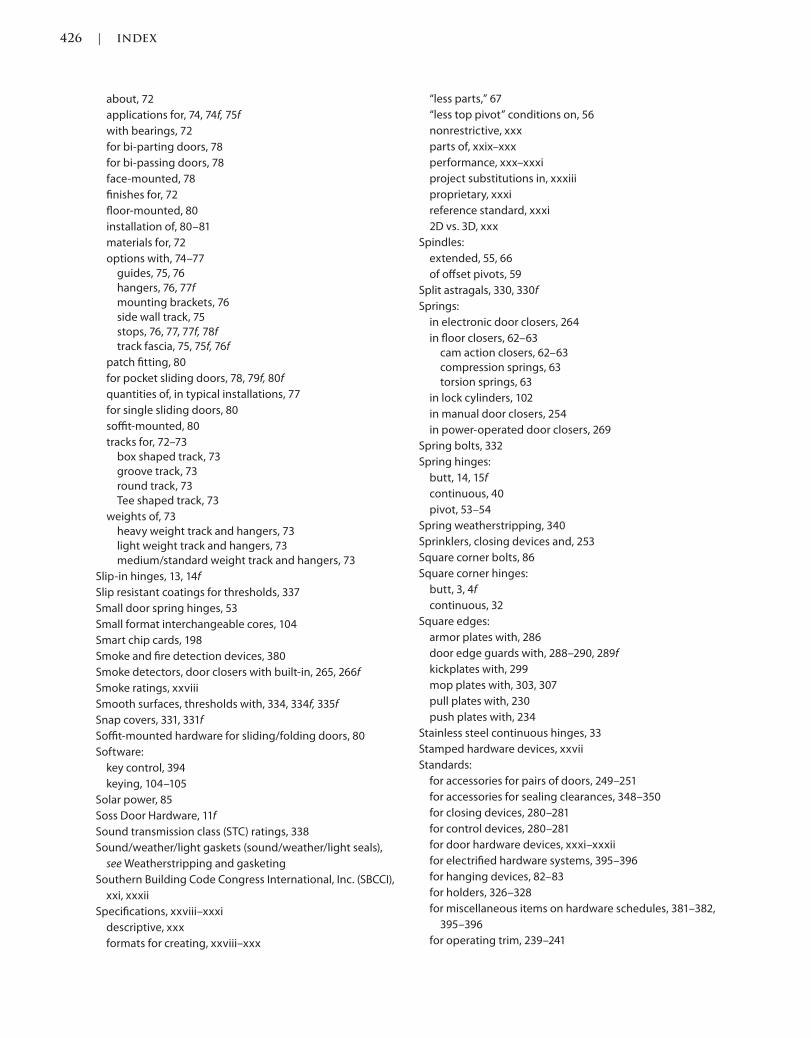
426 | INDEX
Trim: 215 x 276 mm bindex.indd 02/27/2015 05:24:42:PM Page 426
about, 72
applications for, 74, 74f, 75f
with bearings, 72
for bi-parting doors, 78
for bi-passing doors, 78
face-mounted, 78
finishes for, 72
floor-mounted, 80
installation of, 80–81
materials for, 72
options with, 74–77
guides, 75, 76
hangers, 76, 77f
mounting brackets, 76
side wall track, 75
stops, 76, 77, 77f, 78f
track fascia, 75, 75f, 76f
patch fitting, 80
for pocket sliding doors, 78, 79f, 80f
quantities of, in typical installations, 77
for single sliding doors, 80
soffit-mounted, 80
tracks for, 72–73
box shaped track, 73
groove track, 73
round track, 73
Tee shaped track, 73
weights of, 73
heavy weight track and hangers, 73
light weight track and hangers, 73
medium/standard weight track and hangers, 73
Slip-in hinges, 13, 14f
Slip resistant coatings for thresholds, 337
Small door spring hinges, 53
Small format interchangeable cores, 104
Smart chip cards, 198
Smoke and fire detection devices, 380
Smoke detectors, door closers with built-in, 265, 266f
Smoke ratings, xxviii
Smooth surfaces, thresholds with, 334, 334f, 335f
Snap covers, 331, 331f
Soffit-mounted hardware for sliding/folding doors, 80
Software:
key control, 394
keying, 104–105
Solar power, 85
Soss Door Hardware, 11f
Sound transmission class (STC) ratings, 338
Sound/weather/light gaskets (sound/weather/light seals),
see Weatherstripping and gasketing
Southern Building Code Congress International, Inc. (SBCCI),
xxi, xxxii
Specifications, xxviii–xxxi
descriptive, xxx
formats for creating, xxviii–xxx
“less parts,” 67
“less top pivot” conditions on, 56
nonrestrictive, xxx
parts of, xxix–xxx
performance, xxx–xxxi
project substitutions in, xxxiii
proprietary, xxxi
reference standard, xxxi
2D vs. 3D, xxx
Spindles:
extended, 55, 66
of offset pivots, 59
Split astragals, 330, 330f
Springs:
in electronic door closers, 264
in floor closers, 62–63
cam action closers, 62–63
compression springs, 63
torsion springs, 63
in lock cylinders, 102
in manual door closers, 254
in power-operated door closers, 269
Spring bolts, 332
Spring hinges:
butt, 14, 15f
continuous, 40
pivot, 53–54
Spring weatherstripping, 340
Sprinklers, closing devices and, 253
Square corner bolts, 86
Square corner hinges:
butt, 3, 4f
continuous, 32
Square edges:
armor plates with, 286
door edge guards with, 288–290, 289f
kickplates with, 299
mop plates with, 303, 307
pull plates with, 230
push plates with, 234
Stainless steel continuous hinges, 33
Stamped hardware devices, xxvii
Standards:
for accessories for pairs of doors, 249–251
for accessories for sealing clearances, 348–350
for closing devices, 280–281
for control devices, 280–281
for door hardware devices, xxxi–xxxii
for electrified hardware systems, 395–396
for hanging devices, 82–83
for holders, 326–328
for miscellaneous items on hardware schedules, 381–382,
395–396
for operating trim, 239–241
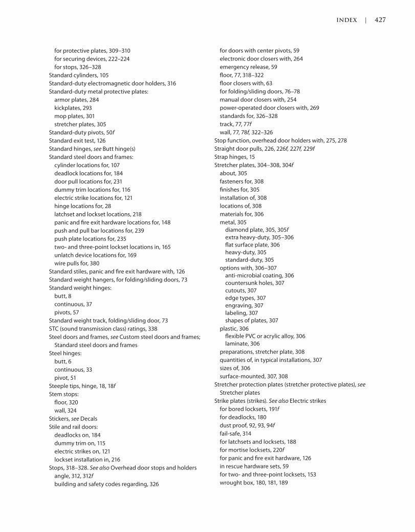
INDEX | 427
bindex.indd 02/27/2015 05:24:42:PM Page 427Trim: 215 x 276 mm
for protective plates, 309–310
for securing devices, 222–224
for stops, 326–328
Standard cylinders, 105
Standard-duty electromagnetic door holders, 316
Standard-duty metal protective plates:
armor plates, 284
kickplates, 293
mop plates, 301
stretcher plates, 305
Standard-duty pivots, 50f
Standard exit test, 126
Standard hinges, see Butt hinge(s)
Standard steel doors and frames:
cylinder locations for, 107
deadlock locations for, 184
door pull locations for, 231
dummy trim locations for, 116
electric strike locations for, 121
hinge locations for, 28
latchset and lockset locations, 218
panic and fire exit hardware locations for, 148
push and pull bar locations for, 239
push plate locations for, 235
two- and three-point lockset locations in, 165
unlatch device locations for, 169
wire pulls for, 380
Standard stiles, panic and fire exit hardware with, 126
Standard weight hangers, for folding/sliding doors, 73
Standard weight hinges:
butt, 8
continuous, 37
pivots, 57
Standard weight track, folding/sliding door, 73
STC (sound transmission class) ratings, 338
Steel doors and frames, see Custom steel doors and frames;
Standard steel doors and frames
Steel hinges:
butt, 6
continuous, 33
pivot, 51
Steeple tips, hinge, 18, 18f
Stem stops:
floor, 320
wall, 324
Stickers, see Decals
Stile and rail doors:
deadlocks on, 184
dummy trim on, 115
electric strikes on, 121
lockset installation in, 216
Stops, 318–328. See also Overhead door stops and holders
angle, 312, 312f
building and safety codes regarding, 326
for doors with center pivots, 59
electronic door closers with, 264
emergency release, 59
floor, 77, 318–322
floor closers with, 63
for folding/sliding doors, 76–78
manual door closers with, 254
power-operated door closers with, 269
standards for, 326–328
track, 77, 77f
wall, 77, 78f, 322–326
Stop function, overhead door holders with, 275, 278
Straight door pulls, 226, 226f, 227f, 229f
Strap hinges, 15
Stretcher plates, 304–308, 304f
about, 305
fasteners for, 308
finishes for, 305
installation of, 308
locations of, 308
materials for, 306
metal, 305
diamond plate, 305, 305f
extra heavy-duty, 305–306
flat surface plate, 306
heavy-duty, 305
standard-duty, 305
options with, 306–307
anti-microbial coating, 306
countersunk holes, 307
cutouts, 307
edge types, 307
engraving, 307
labeling, 307
shapes of plates, 307
plastic, 306
flexible PVC or acrylic alloy, 306
laminate, 306
preparations, stretcher plate, 308
quantities of, in typical installations, 307
sizes of, 306
surface-mounted, 307, 308
Stretcher protection plates (stretcher protective plates), see
Stretcher plates
Strike plates (strikes). See also Electric strikes
for bored locksets, 191f
for deadlocks, 180
dust proof, 92, 93, 94f
fail-safe, 314
for latchsets and locksets, 188
for mortise locksets, 220f
for panic and fire exit hardware, 126
in rescue hardware sets, 59
for two- and three-point locksets, 153
wrought box, 180, 181, 189

428 | INDEX
Trim: 215 x 276 mm bindex.indd 02/27/2015 05:24:42:PM Page 428
Studio Collection™, 113f, 193f, 214f
Submittals, xxxiii
Substitution Request Forms, CSI, xxxiii
Suited door hardware, 211f
Surface bolts (slide bolts). See also Bolts
applications using, 95, 95f–97f
installation of, 96
keyed, 94
manual, 91
with manual locking astragals, 332
nonkeyed, 94
preparations for, 97
quantities of, in typical installations, 94
sizes of, 88
Surface-mounted armor plates, 287
Surface-mounted astragals, 332
Surface-mounted bumper guards, 353
Surface-mounted carry bars, 248
Surface-mounted deadlocks, 183
Surface-mounted door closers:
electronic, 265–267
low-energy, 270f
manual, 254f, 255–257, 261, 262
with motion sensor hold open option, 265, 265f
parallel arm, 255–256, 255f, 265, 270, 271
pneumatic, 267
pot belly, 256, 256f
power-operated, 270–272, 273f
regular arm, 256, 256f, 261, 261f, 265, 271
with smoke detector feature, 265, 266f
top-jamb-mounted, 256–257, 257f, 271
Surface-mounted door edge guards, 290–291
Surface-mounted door holders:
electromagnetic, 317
manual, 313
overhead, 276f, 277, 278
Surface-mounted door position switches, 108, 109
Surface-mounted door pulls, 230
Surface-mounted electric strikes, 121
Surface-mounted floor stops, 322
Surface-mounted kickplates, 299, 300
Surface-mounted locksets:
electromagnetic, 175f, 176, 176f
three-point, 154, 155
two-point, 153, 154, 154f, 164
Surface-mounted mop plates, 303, 304
Surface-mounted panic and fire exit hardware, 147
Surface-mounted pull bars, 238
Surface-mounted push bars, 238
Surface-mounted push plates, 235
Surface-mounted stretcher plates, 307, 308
Surface-mounted thresholds, 338
Surface-mounted wall stops, 325
Surface-mounted weatherstripping, 340f, 341f, 342, 345
Surface rods:
panic and fire exit hardware with, 130, 130f
three-point locksets with, 155, 159
two-point locksets with, 154, 159
Sustainability information, xxxiii, 111
Swaging:
of butt hinges, 7, 8
of continuous hinges, 36
Sweep speed, 255, 264, 270
Sweep speed valves:
in electronic and pneumatic door closers, 264
in manual door closers, 255
in power-operated door closers, 270
Swing-clear hinges:
butt, 15, 16f
continuous, 40–41, 41f, 42f
Swing hinges, standard, 16f
Switches:
access panel, 175
armature, 175
door position, 21, 22, 108–110, 175
with electromagnetic locksets, 175
electronic, 266, 271
electronic and pneumatic door closers with, 264, 266
floor mats with, 271
key, 106, 390, 390f
for power-operated door closers, 271
in power-operated door closers, 269
power-operated door closers with, 271
pushbutton, 391, 392f
request to exit, 134–135, 157, 175, 203
Swiveling armatures, 316, 317f
Symmetry templated continuous hinges, 35
Systems of thresholds, 338
T
Tactile warnings, trim with, 143
Tech-Talks (DHI):
ASD-1 Aluminum Storefront Doors, 82, 222, 240, 250, 280,
309, 327, 381, 395
BH-1 Butts and Hinges, 82
CH-1 Continuous Hinges, 82
EAH-91 Electrified Architectural Hardware, 82, 222, 280,
395
ED-1 Exit Devices, 222
EL-1 Electromagnetic Locks, 222
FC-1 Concealed Floor Closers, 82, 280
HTL-92 Hotel/Motel Hardware and Keying, 222
MK-1 Masterkeying, 222
P-1 Pivots, 82
PH-1 Protective Hardware, 309, 381
SDC-92 Surface Door Closers, 280
SP-1 Hardware Specification Writing, 82, 222, 240, 250,

INDEX | 429
bindex.indd 02/27/2015 05:24:42:PM Page 429Trim: 215 x 276 mm
280, 309
WS-1/Rev Gasketing and Thresholds, 349
Tee astragals, overlapping, 331, 331f
Tee hinges, 16, 17f
Tee-shaped removable mullions, 149, 149f
Tee-shaped track, folding/sliding door, 73
Templated hinges, 5, 5f
Tests for Door Stops, 319, 323
Thermal break surfaces, 332, 334, 334f, 344, 348f
3D specifications, xxx
Three-knuckle hinges, 5, 6f
Three-point locksets, 151–165
about, 151
actuating bars of, 151–152
crossbar actuators, 151–152, 152f
touchpad actuators, 152, 152f
chassis of, 152
concealed, 164
with concealed vertical top and bottom rods, 154–155
fasteners for, 165
finishes for, 153
grades of, 153
installation of, 164–165
locations of, 165
materials for, 153
mortise, 155, 164
options with, 155–163
anti-microbial coating, 155
auxiliary control, 155
connectors, 155
cylinders, 156
dogging, 156
electrical options, 156–157
fire ratings, 158
handing, 158, 158f
hurricane rating, 158, 159f
latching, 159–160
luminous materials, 160, 160f, 161f
for specific functions, 158
trim, 160–163, 162f
preparations, lockset, 165
quantities of, in typical installations, 163
rim, 155
strikes of, 153
with surface vertical top and bottom rods, 155
Thresholds, 333–339
about, 333
adjustable, 335, 335f
bulkhead, 335
compression, 335
for covering floor closers, 337
expansion joint, 335
fasteners for, 338
finishes for, 334
floor closers with, 67
half-, 335, 335f
installation of, 338–339
fasteners, 338
locations, 338
preparations, 339
interlocking, 336
latching panic, 336, 336f
locations of, 338
materials for, 334
options with, 337–338
anchors, 337
barrier free, 337
coatings, 337
cutouts, 338
epoxy-filled surfaces, 337
sound transmission class ratings, 338
systems of thresholds, 338
plate, with fluted surfaces, 336
preparations, threshold, 339
quantities of, in typical installations, 338
rabbeted, 336
ramped barrier free, 336, 336f
recessed, 338
for residential door openings, 336, 337f
saddles, 337
sizes of, 337
surface-mounted, 338
surfaces of, 334–335
broken, 334, 334f
epoxy-filled, 337
fluted, 334, 334f, 336
smooth, 334, 334f, 335f
Threshold guides, 76
Through-bolt fasteners:
for door pulls, 231
for push and pull bars, 238
Throw, bolt, 86
Thrust bearings:
floor closers with, 62
pivots with, 50
Thrust pivots, 54
Thumb-turn mechanisms:
for deadlocks, 180, 181f
for locksets, 188, 188f
for mortise locksets, 194f
panic and fire exit hardware with, 131
security classroom exit devices with, 137f
for tubular latchsets, 195
for two- and three-point locksets, 155
Timers:
automatic relock, 171
electronic door closers with, 266
exit delay, 173, 173f
power-operated door closers with, 272
Top, center, and bottom latching:

430 | INDEX
Trim: 215 x 276 mm bindex.indd 02/27/2015 05:24:42:PM Page 430
of panic and exit hardware, 138–139
of two- and three-point locksets, 160
Top and bottom latching:
of panic and exit hardware, 138
of two- and three-point locksets, 159
Top-jamb-mounted surface-mounted door closers:
electronic, 266
manual, 256–257, 257f
power-operated, 271
Top latching, of panic and exit hardware, 138
Top pivots, 51–53
center, 53, 53f
full and half surface, 59
half mortise, 59
offset, 51f, 52, 52f
Torsion door spring hinges, 54
Torsion springs, floor closers with, 63
Touchpad actuators:
in panic and fire exit hardware, 123, 123f
in two- and three-point locksets, 152, 152f
Touch sense bars, 141
Towel hooks, see Coat hooks
Track, folding/sliding door, 72–73
box shaped track, 73
fascia of, 75, 75f, 76f
groove track, 73
round track, 73
Tee shaped track, 73
Track stops, 77, 77f
Trigger door position switches, 108
Trim. See also Dummy trim; Operating trim
anti-vandal, 141–142, 142f, 161, 209
behavioral health, 209, 209f, 210f
decorative, 142, 143f, 161, 210, 211f
electrified, 142, 143, 157, 161, 210, 212f
for electrified locksets, 203
escutcheons, 143, 144f, 161, 162f, 212, 212f
with hazard or tactile warnings, 143, 161, 163
hazard warning, 212–213
heavy-duty, 143, 163, 213
knob, 141, 144, 163, 213
for latchsets and locksets, 208–213, 214f–215f
lever, 141, 142, 142f, 144, 161, 162f, 163, 213
for panic and fire exits, 141–146, 145f
pull, 145, 145f, 163, 164f
rigid, 146, 163, 213
rosettes, 146, 163, 213
of two- and three-point locksets, 160–163, 162f
Tube devices, for panic and fire exits, 141, 147
Tubular deadlocks, 178f, 182–183, 183f
Tubular dummy trim, 111
Tubular latchsets, 195
Tubular locksets, 195, 195f
20-minute fire doors, xxviii
2D specifications, xxx
Two-knuckle hinges, 5, 6, 6f
Two-point locksets, 151–165
about, 151
actuating bars of, 151–152
crossbar actuators, 151–152, 152f
touchpad actuators, 152, 152f
chassis of, 152
concealed, 164
with concealed vertical top and bottom rods, 153–154,
153f
fasteners for, 165
finishes for, 153
grades of, 153
installation of, 164–165
locations of, 165
materials for, 153
mortise, 154, 164
options with, 155–163
anti-microbial coating, 155
auxiliary control, 155
connectors, 155
cylinders, 156
dogging, 156
electrical options, 156–157
fire ratings, 158
handing, 158, 158f
hurricane rating, 158, 159f
latching, 159–160
luminous materials, 160, 160f, 161f
for specific functions, 158
trim, 160–163, 162f
preparations, lockset, 165
quantities of, in typical installations, 163
rim, 154
strikes of, 153
surface, 154, 154f
surface-mounted, 164
Two-sided angle plates:
armor plates as, 287
kickplates as, 299
mop plates as, 303
U
Underwriters’ Electrical Bureau, xx
Underwriters Laboratories (UL), xx, xxviii, xxxii, 56
Underwriters Laboratories (UL) standards:
on accessories for sealing clearances, 350
on securing devices, 224
UL 10B, Fire Tests of Door Assemblies, 350
UL 10C, Positive Pressure Fire Tests of Door Assemblies,
350
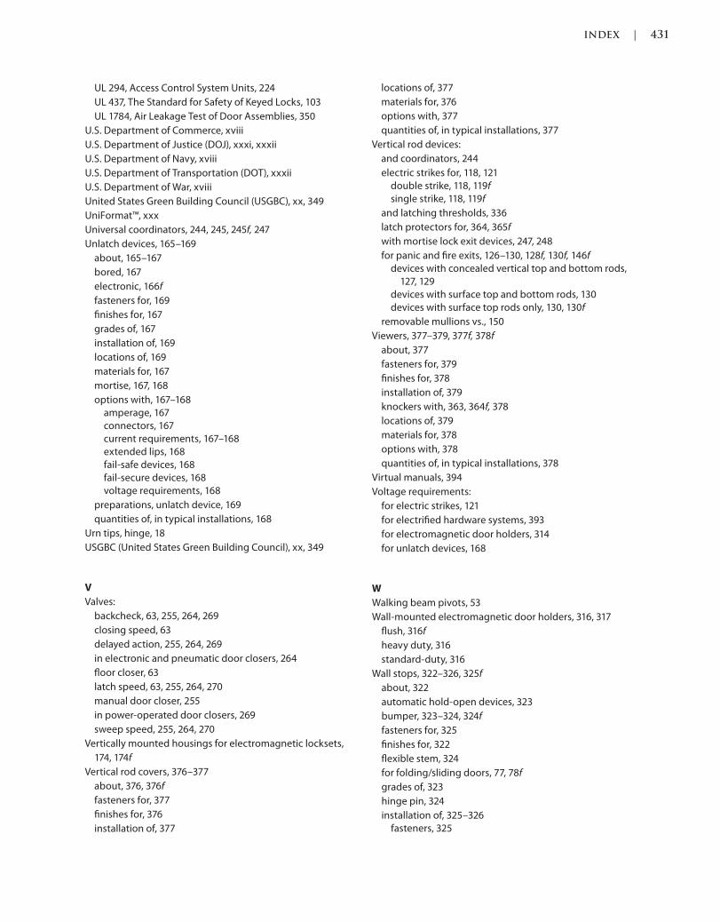
INDEX | 431
bindex.indd 02/27/2015 05:24:42:PM Page 431Trim: 215 x 276 mm
UL 294, Access Control System Units, 224
UL 437, The Standard for Safety of Keyed Locks, 103
UL 1784, Air Leakage Test of Door Assemblies, 350
U.S. Department of Commerce, xviii
U.S. Department of Justice (DOJ), xxxi, xxxii
U.S. Department of Navy, xviii
U.S. Department of Transportation (DOT), xxxii
U.S. Department of War, xviii
United States Green Building Council (USGBC), xx, 349
UniFormat™, xxx
Universal coordinators, 244, 245, 245f, 247
Unlatch devices, 165–169
about, 165–167
bored, 167
electronic, 166f
fasteners for, 169
finishes for, 167
grades of, 167
installation of, 169
locations of, 169
materials for, 167
mortise, 167, 168
options with, 167–168
amperage, 167
connectors, 167
current requirements, 167–168
extended lips, 168
fail-safe devices, 168
fail-secure devices, 168
voltage requirements, 168
preparations, unlatch device, 169
quantities of, in typical installations, 168
Urn tips, hinge, 18
USGBC (United States Green Building Council), xx, 349
V
Valves:
backcheck, 63, 255, 264, 269
closing speed, 63
delayed action, 255, 264, 269
in electronic and pneumatic door closers, 264
floor closer, 63
latch speed, 63, 255, 264, 270
manual door closer, 255
in power-operated door closers, 269
sweep speed, 255, 264, 270
Vertically mounted housings for electromagnetic locksets,
174, 174f
Vertical rod covers, 376–377
about, 376, 376f
fasteners for, 377
finishes for, 376
installation of, 377
locations of, 377
materials for, 376
options with, 377
quantities of, in typical installations, 377
Vertical rod devices:
and coordinators, 244
electric strikes for, 118, 121
double strike, 118, 119f
single strike, 118, 119f
and latching thresholds, 336
latch protectors for, 364, 365f
with mortise lock exit devices, 247, 248
for panic and fire exits, 126–130, 128f, 130f, 146f
devices with concealed vertical top and bottom rods,
127, 129
devices with surface top and bottom rods, 130
devices with surface top rods only, 130, 130f
removable mullions vs., 150
Viewers, 377–379, 377f, 378f
about, 377
fasteners for, 379
finishes for, 378
installation of, 379
knockers with, 363, 364f, 378
locations of, 379
materials for, 378
options with, 378
quantities of, in typical installations, 378
Virtual manuals, 394
Voltage requirements:
for electric strikes, 121
for electrified hardware systems, 393
for electromagnetic door holders, 314
for unlatch devices, 168
W
Walking beam pivots, 53
Wall-mounted electromagnetic door holders, 316, 317
flush, 316f
heavy duty, 316
standard-duty, 316
Wall stops, 322–326, 325f
about, 322
automatic hold-open devices, 323
bumper, 323–324, 324f
fasteners for, 325
finishes for, 322
flexible stem, 324
for folding/sliding doors, 77, 78f
grades of, 323
hinge pin, 324
installation of, 325–326
fasteners, 325
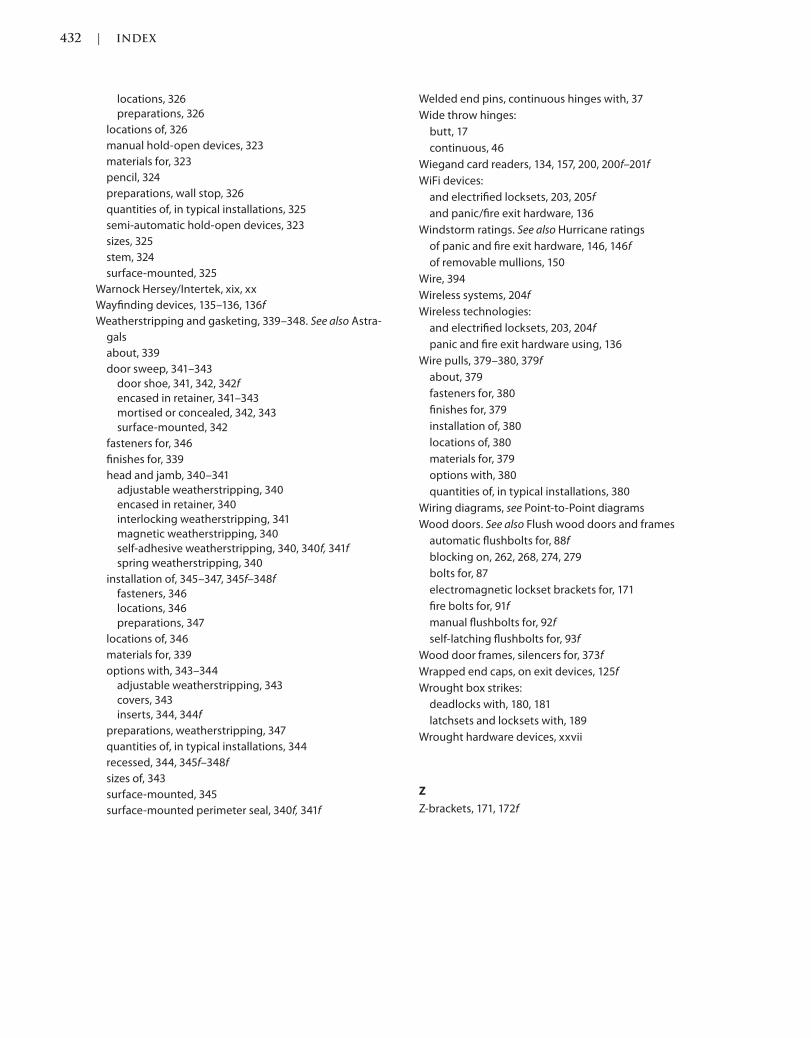
432 | INDEX
Trim: 215 x 276 mm bindex.indd 02/27/2015 05:24:42:PM Page 432
locations, 326
preparations, 326
locations of, 326
manual hold-open devices, 323
materials for, 323
pencil, 324
preparations, wall stop, 326
quantities of, in typical installations, 325
semi-automatic hold-open devices, 323
sizes, 325
stem, 324
surface-mounted, 325
Warnock Hersey/Intertek, xix, xx
Wayfinding devices, 135–136, 136f
Weatherstripping and gasketing, 339–348. See also Astra-
gals
about, 339
door sweep, 341–343
door shoe, 341, 342, 342f
encased in retainer, 341–343
mortised or concealed, 342, 343
surface-mounted, 342
fasteners for, 346
finishes for, 339
head and jamb, 340–341
adjustable weatherstripping, 340
encased in retainer, 340
interlocking weatherstripping, 341
magnetic weatherstripping, 340
self-adhesive weatherstripping, 340, 340f, 341f
spring weatherstripping, 340
installation of, 345–347, 345f–348f
fasteners, 346
locations, 346
preparations, 347
locations of, 346
materials for, 339
options with, 343–344
adjustable weatherstripping, 343
covers, 343
inserts, 344, 344f
preparations, weatherstripping, 347
quantities of, in typical installations, 344
recessed, 344, 345f–348f
sizes of, 343
surface-mounted, 345
surface-mounted perimeter seal, 340f, 341f
Welded end pins, continuous hinges with, 37
Wide throw hinges:
butt, 17
continuous, 46
Wiegand card readers, 134, 157, 200, 200f–201f
WiFi devices:
and electrified locksets, 203, 205f
and panic/fire exit hardware, 136
Windstorm ratings. See also Hurricane ratings
of panic and fire exit hardware, 146, 146f
of removable mullions, 150
Wire, 394
Wireless systems, 204f
Wireless technologies:
and electrified locksets, 203, 204f
panic and fire exit hardware using, 136
Wire pulls, 379–380, 379f
about, 379
fasteners for, 380
finishes for, 379
installation of, 380
locations of, 380
materials for, 379
options with, 380
quantities of, in typical installations, 380
Wiring diagrams, see Point-to-Point diagrams
Wood doors. See also Flush wood doors and frames
automatic flushbolts for, 88f
blocking on, 262, 268, 274, 279
bolts for, 87
electromagnetic lockset brackets for, 171
fire bolts for, 91f
manual flushbolts for, 92f
self-latching flushbolts for, 93f
Wood door frames, silencers for, 373f
Wrapped end caps, on exit devices, 125f
Wrought box strikes:
deadlocks with, 180, 181
latchsets and locksets with, 189
Wrought hardware devices, xxvii
Z
Z-brackets, 171, 172f

WILEY END USER LICENSE AGREEMENTGo to www.wiley.com/go/eula to access Wiley’s ebook EULA.


![[The story] says that a little boy fell into1.droppdf.com/files/qzTmG/the-third-plantagenet-george... · 2015-08-28 · [The story] says that a little boy fell into a well, and there](https://img.pdfslide.net/doc/110x75/5e6eca3663fdbc294505dea0/the-story-says-that-a-little-boy-fell-into1-2015-08-28-the-story-says-that.jpg)