Embed Size (px)
Citation preview
Trimble Building Construction Division 10355 Westmoor Drive, Westminster CO 80021
© 2012, Trimble Navigation Limited. All rights reserved. Trimble and the Globe & Triangle logo are trademarks of Trimble Navigation Limited, registered in the United States and in other countries. All other trademarks are the property of their respective owners.
www.trimble.com/BuildingConstruction Page 1
Trimble Field Link Software This document explains how to quickly begin using Trimble® Field Link software. Trimble Field Link software enables you to easily lay out your projects with a task-based workflow. The software is designed to more easily utilize CAD files to integrate with modern construction workflows. With new reporting methods, Trimble Field Link software can provide metrics on productivity and improve field communications. The following options are described: Jobs menu .............................................................................................................................................. 2
Manage tool ...................................................................................................................................................... 2 Opening an existing file ................................................................................................................................ 2
Import tool ........................................................................................................................................................ 2 Importing a background file (or 3D model): ................................................................................................. 2
Create Data menu .................................................................................................................................. 3 Create From CAD tool ...................................................................................................................................... 3 Offset Points tool .............................................................................................................................................. 4
Settings menu ........................................................................................................................................ 5 Instrument settings ............................................................................................................................................ 6
Connecting to the instrument ........................................................................................................................ 6 Establishing level and temperature ............................................................................................................... 6 Selecting a target ........................................................................................................................................... 7 Establishing a measure .................................................................................................................................. 7 Setting the calibration ................................................................................................................................... 7 Instrument settings options ........................................................................................................................... 8
Lay Out menu ........................................................................................................................................ 8 Set Up Instrument ............................................................................................................................................. 8 Points ................................................................................................................................................................ 9
Collect Data menu ............................................................................................................................... 11 Set Up Instrument ........................................................................................................................................... 11 Points .............................................................................................................................................................. 11 Linework ......................................................................................................................................................... 12
Reports menu ....................................................................................................................................... 13 Daily Layout Summary ................................................................................................................................... 13 Layout Deviations ........................................................................................................................................... 14 Field Report .................................................................................................................................................... 14
www.trimble.com/BuildingConstruction Page 2
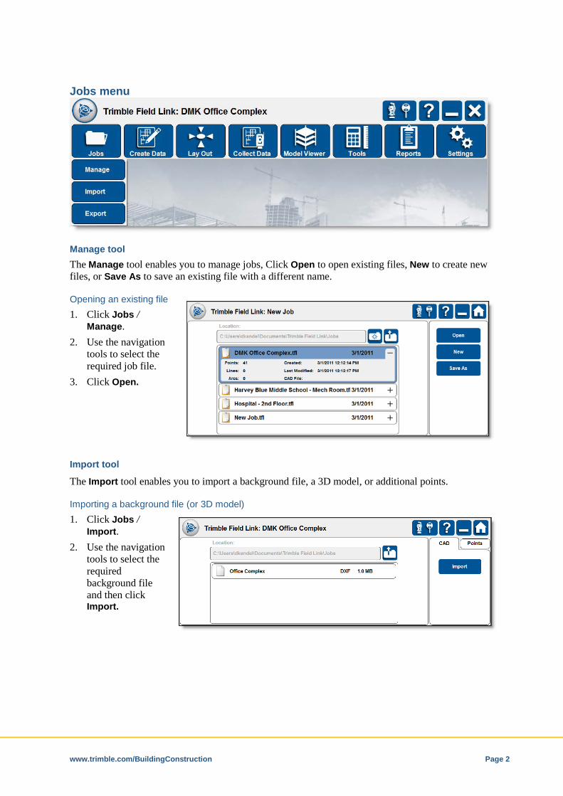
Jobs menu
Manage tool The Manage tool enables you to manage jobs, Click Open to open existing files, New to create new files, or Save As to save an existing file with a different name.
Opening an existing file 1. Click Jobs /
Manage. 2. Use the navigation
tools to select the required job file.
3. Click Open.
Import tool
The Import tool enables you to import a background file, a 3D model, or additional points.
Importing a background file (or 3D model) 1. Click Jobs /
Import. 2. Use the navigation
tools to select the required background file and then click Import.
www.trimble.com/BuildingConstruction Page 3
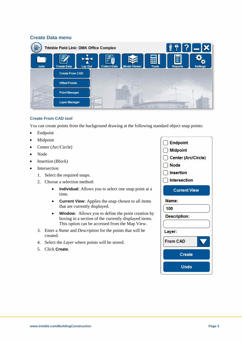
Create Data menu
Create From CAD tool
You can create points from the background drawing at the following standard object snap points: • Endpoint • Midpoint • Center (Arc/Circle) • Node • Insertion (Block) • Intersection
1. Select the required snaps. 2. Choose a selection method:
• Individual: Allows you to select one snap point at a time.
• Current View: Applies the snap chosen to all items that are currently displayed.
• Window: Allows you to define the point creation by boxing in a section of the currently displayed items. This option can be accessed from the Map View.
3. Enter a Name and Description for the points that will be created.
4. Select the Layer where points will be stored. 5. Click Create.
www.trimble.com/BuildingConstruction Page 4
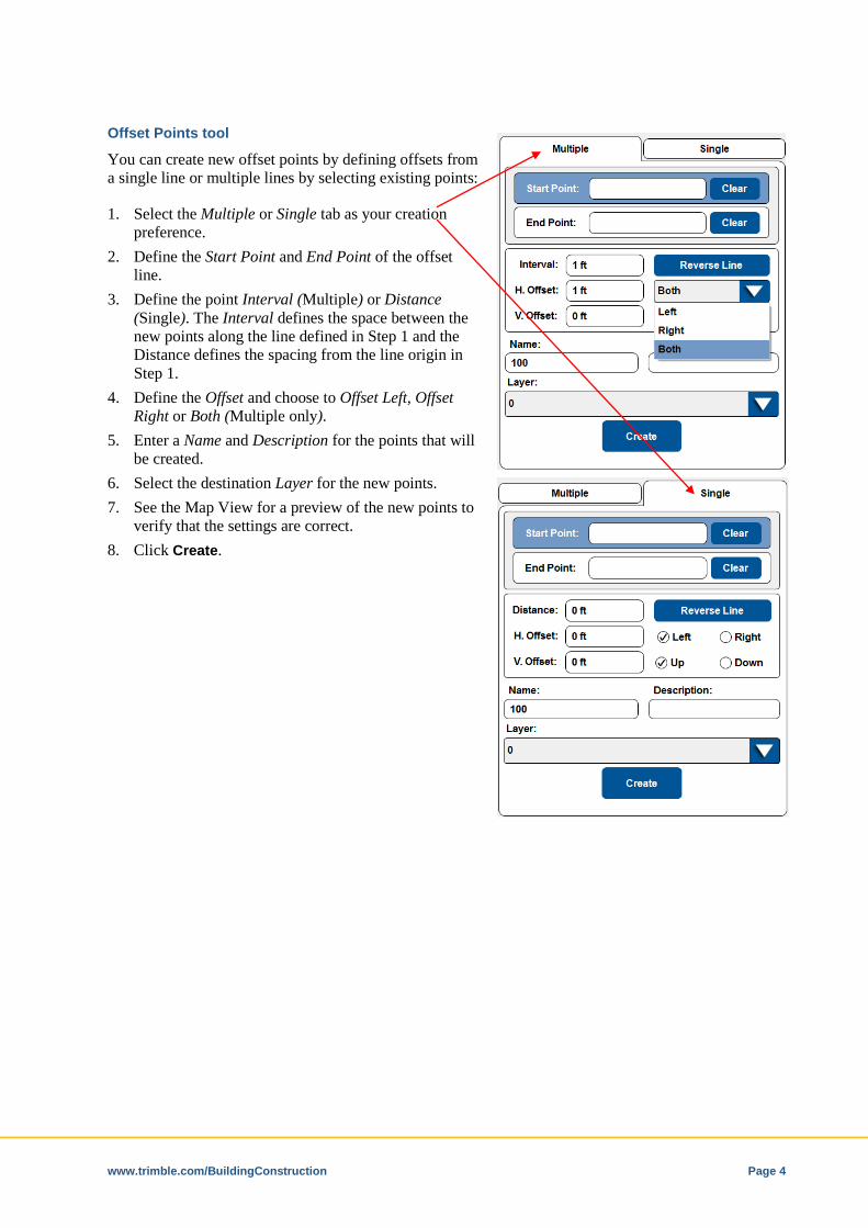
Offset Points tool
You can create new offset points by defining offsets from a single line or multiple lines by selecting existing points:
1. Select the Multiple or Single tab as your creation preference.
2. Define the Start Point and End Point of the offset line.
3. Define the point Interval (Multiple) or Distance (Single). The Interval defines the space between the new points along the line defined in Step 1 and the Distance defines the spacing from the line origin in Step 1.
4. Define the Offset and choose to Offset Left, Offset Right or Both (Multiple only).
5. Enter a Name and Description for the points that will be created.
6. Select the destination Layer for the new points. 7. See the Map View for a preview of the new points to
verify that the settings are correct. 8. Click Create.
www.trimble.com/BuildingConstruction Page 5
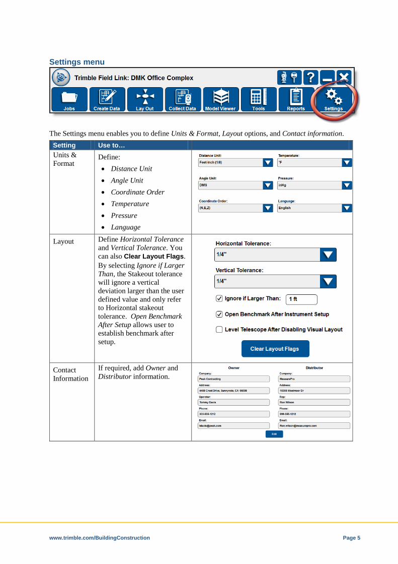
Settings menu
The Settings menu enables you to define Units & Format, Layout options, and Contact information.
Setting Use to… Units & Format
Define: • Distance Unit • Angle Unit • Coordinate Order • Temperature • Pressure • Language
Layout Define Horizontal Tolerance and Vertical Tolerance. You can also Clear Layout Flags. By selecting Ignore if Larger Than, the Stakeout tolerance will ignore a vertical deviation larger than the user defined value and only refer to Horizontal stakeout tolerance. Open Benchmark After Setup allows user to establish benchmark after setup.
Contact Information
If required, add Owner and Distributor information.
www.trimble.com/BuildingConstruction Page 6
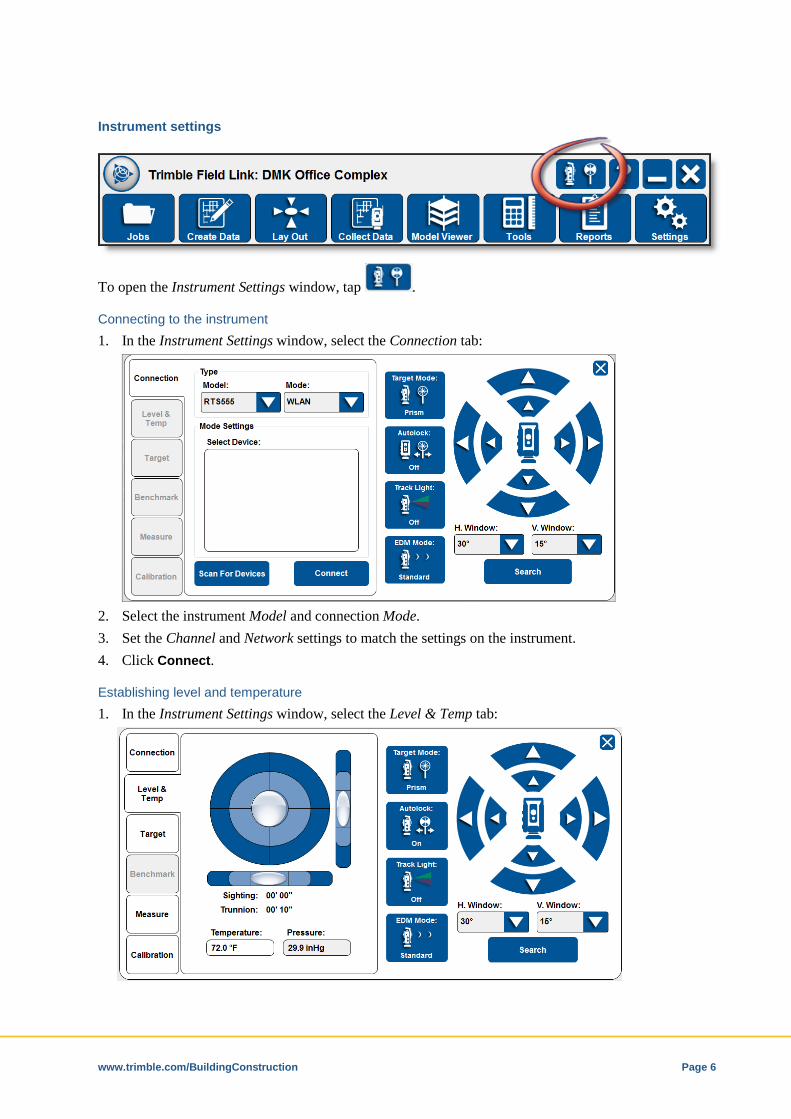
Instrument settings
To open the Instrument Settings window, tap .
Connecting to the instrument 1. In the Instrument Settings window, select the Connection tab:
2. Select the instrument Model and connection Mode. 3. Set the Channel and Network settings to match the settings on the instrument. 4. Click Connect.
Establishing level and temperature 1. In the Instrument Settings window, select the Level & Temp tab:

www.trimble.com/BuildingConstruction Page 7
2. Enter the ambient Temperature. The Pressure is read from the instrument.
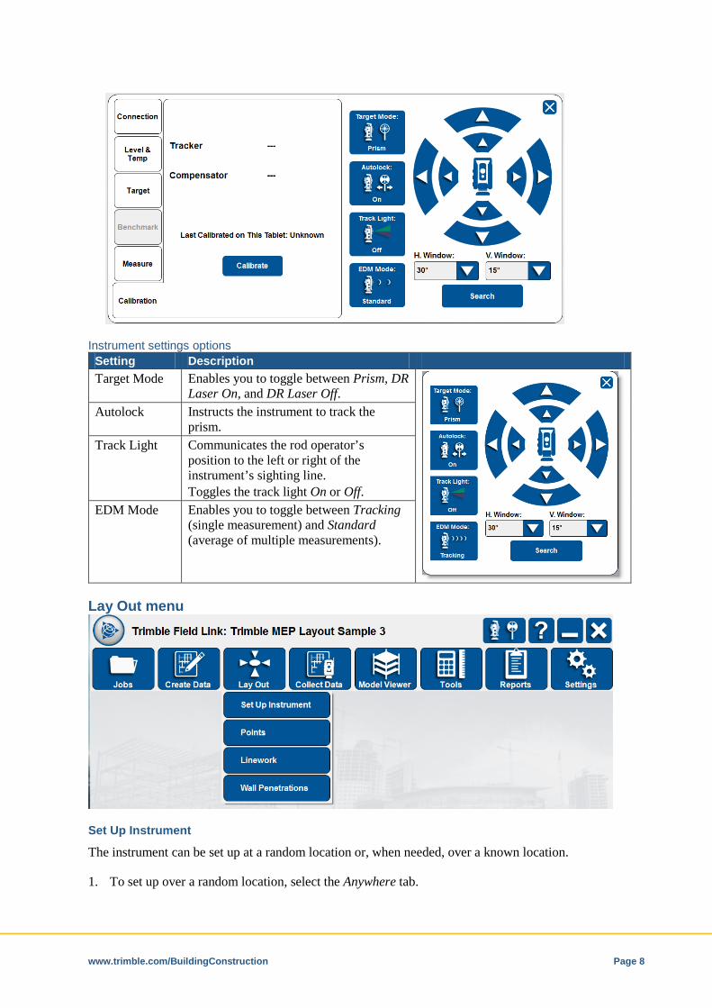
Selecting a target 1. In the Instrument Settings window, select the Target tab:
2. Enter the Rod Height. 3. Select the Target Type from the drop-down list.
Establishing a measure 1. In the Instrument Settings window, select the Measure tab.
2. While connected to the instrument, click Measure. 3. Click the HD/VD toggle button to define display options.
Setting the calibration 1. In the Instrument Settings window, select the Calibration tab. 2. While connected to the instrument, define a measurement surface (target prism) approximately
100m from the instrument location. 3. Click Calibrate.
www.trimble.com/BuildingConstruction Page 8
Instrument settings options Setting Description Target Mode Enables you to toggle between Prism, DR
Laser On, and DR Laser Off.
Autolock Instructs the instrument to track the prism.
Track Light Communicates the rod operator’s position to the left or right of the instrument’s sighting line. Toggles the track light On or Off.
EDM Mode Enables you to toggle between Tracking (single measurement) and Standard (average of multiple measurements).
Lay Out menu
Set Up Instrument
The instrument can be set up at a random location or, when needed, over a known location.
1. To set up over a random location, select the Anywhere tab.
www.trimble.com/BuildingConstruction Page 9
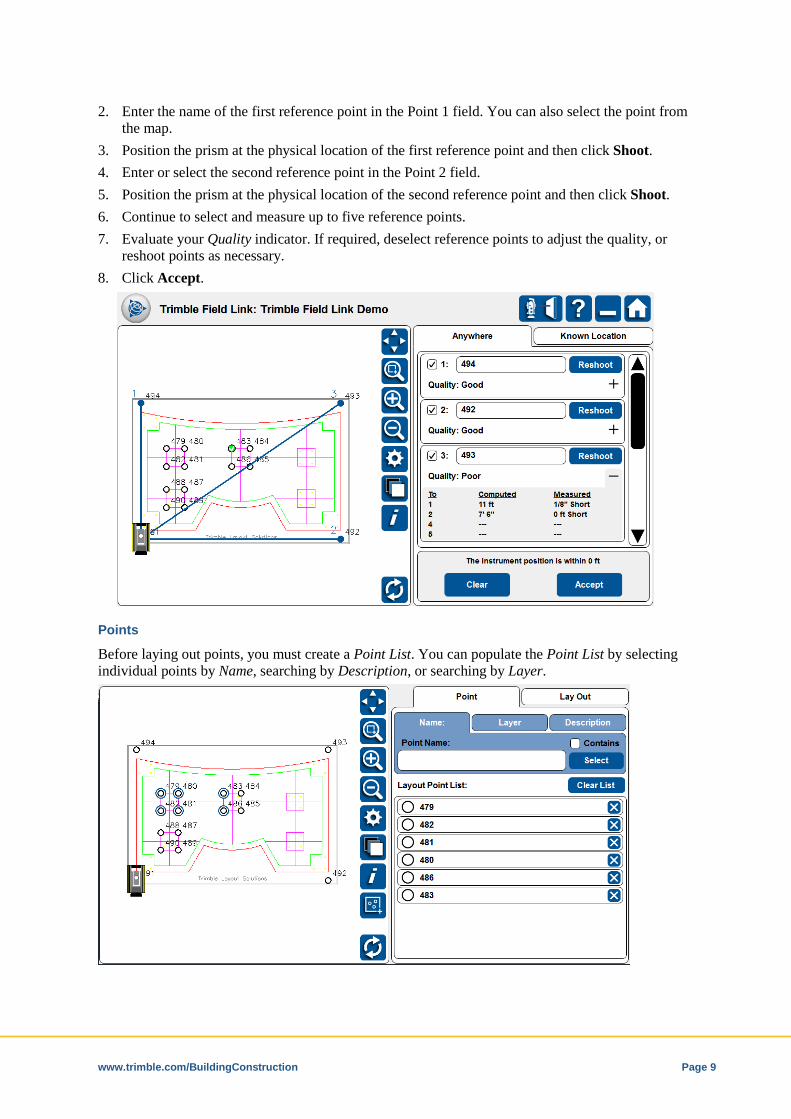
2. Enter the name of the first reference point in the Point 1 field. You can also select the point from the map.
3. Position the prism at the physical location of the first reference point and then click Shoot. 4. Enter or select the second reference point in the Point 2 field. 5. Position the prism at the physical location of the second reference point and then click Shoot. 6. Continue to select and measure up to five reference points. 7. Evaluate your Quality indicator. If required, deselect reference points to adjust the quality, or
reshoot points as necessary. 8. Click Accept.
Points
Before laying out points, you must create a Point List. You can populate the Point List by selecting individual points by Name, searching by Description, or searching by Layer.
www.trimble.com/BuildingConstruction Page 10
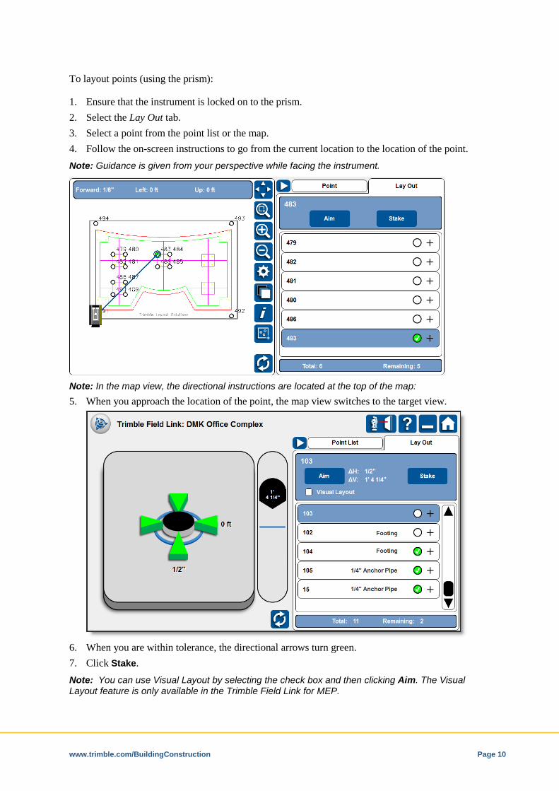
To layout points (using the prism):
1. Ensure that the instrument is locked on to the prism. 2. Select the Lay Out tab. 3. Select a point from the point list or the map. 4. Follow the on-screen instructions to go from the current location to the location of the point. Note: Guidance is given from your perspective while facing the instrument.
Note: In the map view, the directional instructions are located at the top of the map: 5. When you approach the location of the point, the map view switches to the target view.
6. When you are within tolerance, the directional arrows turn green. 7. Click Stake. Note: You can use Visual Layout by selecting the check box and then clicking Aim. The Visual Layout feature is only available in the Trimble Field Link for MEP.

www.trimble.com/BuildingConstruction Page 11
Collect Data menu
Set Up Instrument
See Set Up Instrument, page 9.
Points 1. Position the prism or the laser pointer on the location to be measured. 2. Enter a Name and a Description, and select a Layer.
3. Click Measure.
www.trimble.com/BuildingConstruction Page 12
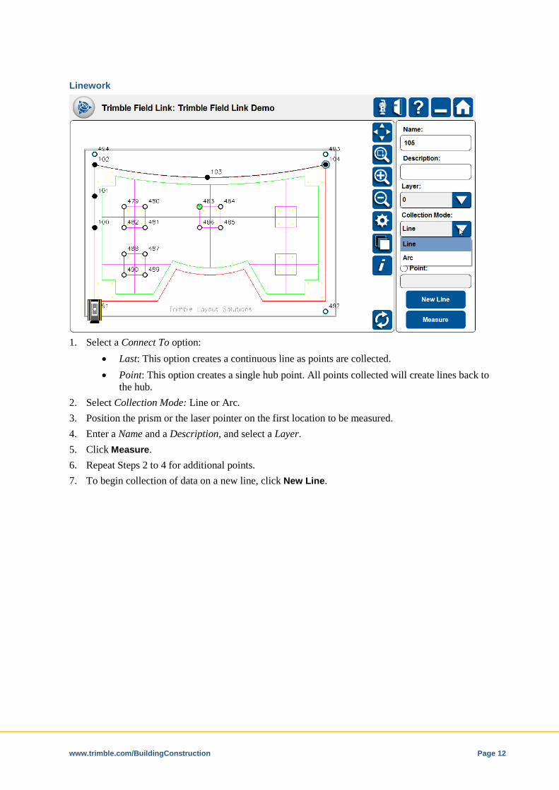
Linework
1. Select a Connect To option:
• Last: This option creates a continuous line as points are collected. • Point: This option creates a single hub point. All points collected will create lines back to
the hub. 2. Select Collection Mode: Line or Arc. 3. Position the prism or the laser pointer on the first location to be measured. 4. Enter a Name and a Description, and select a Layer. 5. Click Measure. 6. Repeat Steps 2 to 4 for additional points. 7. To begin collection of data on a new line, click New Line.
www.trimble.com/BuildingConstruction Page 13
Reports menu
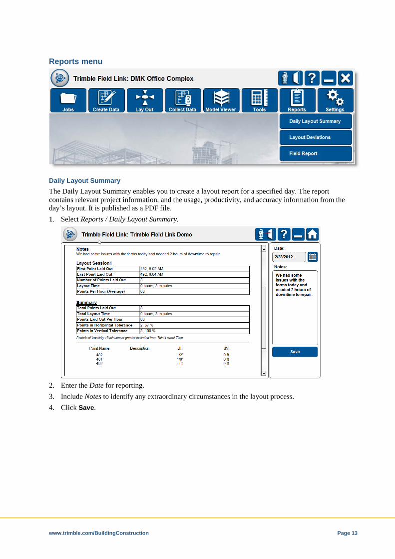
Daily Layout Summary The Daily Layout Summary enables you to create a layout report for a specified day. The report contains relevant project information, and the usage, productivity, and accuracy information from the day’s layout. It is published as a PDF file. 1. Select Reports / Daily Layout Summary.
2. Enter the Date for reporting. 3. Include Notes to identify any extraordinary circumstances in the layout process. 4. Click Save.
www.trimble.com/BuildingConstruction Page 14
Layout Deviations The Layout Deviation report enables you to create spreadsheet style layout data for a range of dates. The data strictly addresses the delta values (in X, Y, and Z), for points that were laid out in the range of dates defined. 1. Select Reports / Layout Deviation Report.
2. Enter the required Start and End date for reporting. 3. Under Include, select any additional data to include in the report and then click Save.
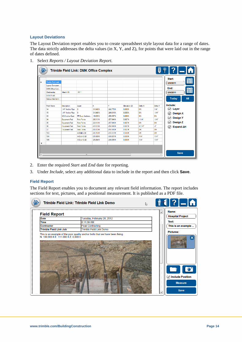
Field Report The Field Report enables you to document any relevant field information. The report includes sections for text, pictures, and a positional measurement. It is published as a PDF file.