Embed Size (px)
Citation preview
GASTECH 2002
“Trinidad LNG – The Second Wave”
P. HunterManager of LNG Technology & Start Up
Bechtel Petroleum & Chemicals Global Business Unit
D. AndressLNG Licensing Group
ConocoPhillips
P.HUNTER 2
“Trinidad LNG – The Second Wave”
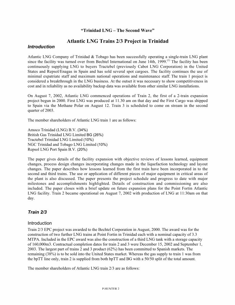
Atlantic LNG Trains 2/3 Project in TrinidadIntroduction
Atlantic LNG Company of Trinidad & Tobago has been successfully operating a single-train LNG plantsince the facility was turned over from Bechtel International on June 14th, 1999.(1) The facility has beencontinuously supplying LNG to buyers Tractebel (previously Cabot LNG Corporation) in the UnitedStates and Repsol/Enagas in Spain and has sold several spot cargoes. The facility continues the use ofminimal expatriate staff and maximum national operations and maintenance staff. The train 1 project isconsidered a breakthrough in the LNG business. At the outset it was necessary to show competitiveness incost and in reliability as no availability backup data was available from other similar LNG installations.
On August 7, 2002, Atlantic LNG commenced operations of Train 2, the first of a 2-train expansionproject begun in 2000. First LNG was produced at 11.30 am on that day and the First Cargo was shippedto Spain via the Methane Polar on August 12. Train 3 is scheduled to come on stream in the secondquarter of 2003.
The member shareholders of Atlantic LNG train 1 are as follows:
Amoco Trinidad (LNG) B.V. (34%)British Gas Trinidad LNG Limited BG (26%)Tractebel Trinidad LNG Limited (10%)NGC Trinidad and Tobago LNG Limited (10%)Repsol LNG Port Spain B.V. (20%)
The paper gives details of the facility expansion with objective reviews of lessons learned, equipmentchanges, process design changes incorporating changes made in the liquefaction technology and layoutchanges. The paper describes how lessons learned from the first train have been incorporated in to thesecond and third trains. The use or application of different pieces of major equipment in critical areas ofthe plant is also discussed. The paper presents the project schedule and progress to date with majormilestones and accomplishments highlighted. Details of construction and commissioning are alsoincluded. The paper closes with a brief update on future expansion plans for the Point Fortin AtlanticLNG facility. Train 2 became operational on August 7, 2002 with production of LNG at 11:30am on thatday.
Train 2/3
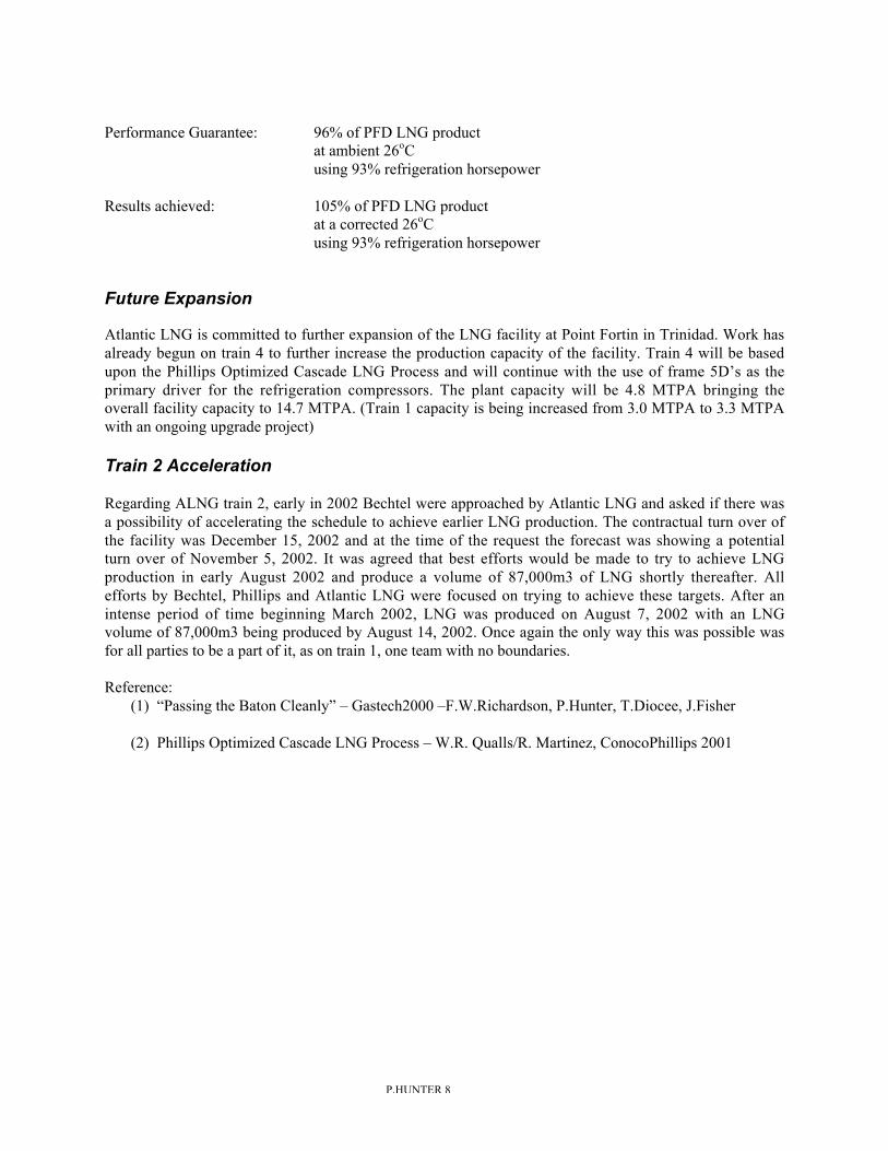
IntroductionTrain 2/3 EPC project was awarded to the Bechtel Corporation in August, 2000. The award was for theconstruction of two further LNG trains at Point Fortin in Trinidad each with a nominal capacity of 3.3MTPA. Included in the EPC award was also the construction of a third LNG tank with a storage capacityof 160,000m3. Contractual completion dates for train 2 and 3 were December 15, 2002 and September 1,2003. The largest part of trains 2 and 3 product (62%) has been committed to Spanish markets. Theremaining (38%) is to be sold into the United States market. Whereas the gas supply to train 1 was fromthe bpTT line only, train 2 is supplied from both bpTT and BG with a 50/50 split of the total amount.
The member shareholders of Atlantic LNG train 2/3 are as follows:
P.HUNTER 3
Amoco Trinidad LNG LLC (42.5%)British Gas Global Investments B.V. (32.5%)Repsol Overzee Financien B.V. (25.0%)
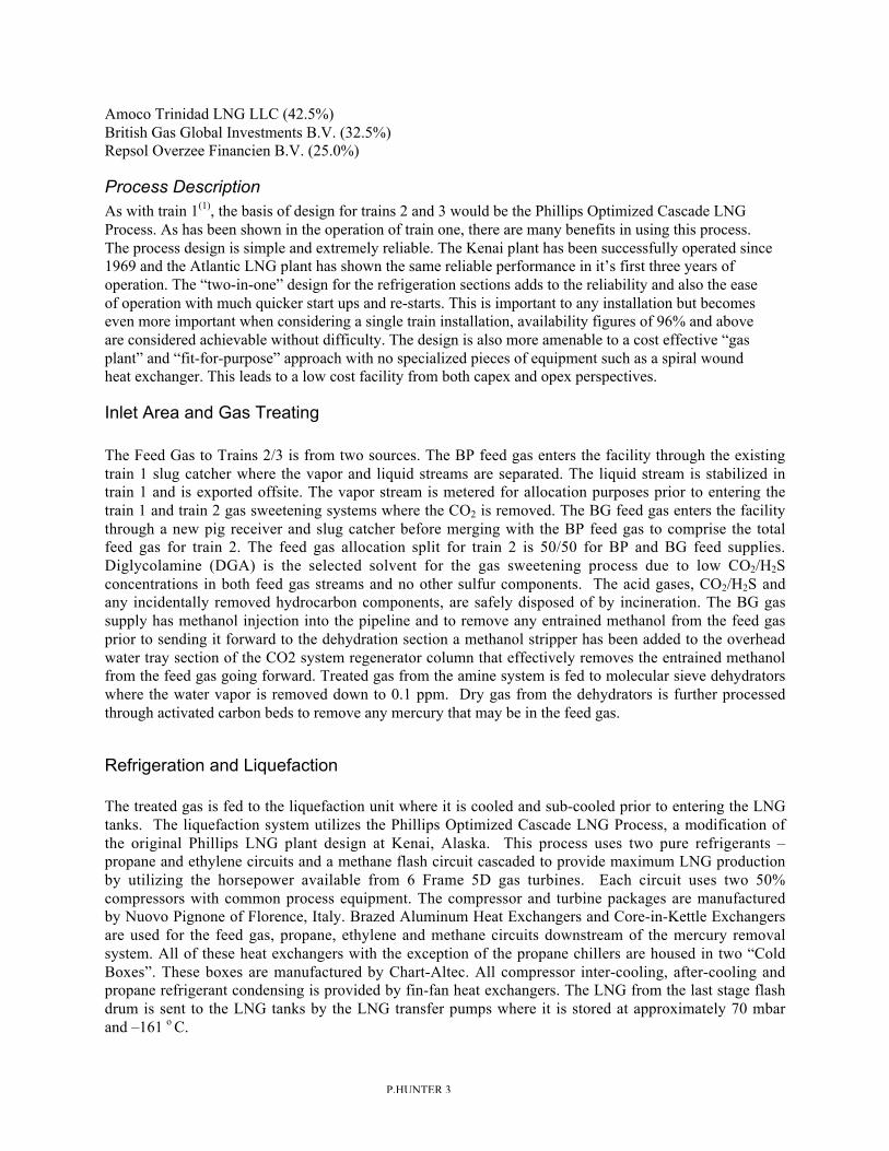
Process DescriptionAs with train 1(1), the basis of design for trains 2 and 3 would be the Phillips Optimized Cascade LNGProcess. As has been shown in the operation of train one, there are many benefits in using this process.The process design is simple and extremely reliable. The Kenai plant has been successfully operated since1969 and the Atlantic LNG plant has shown the same reliable performance in it’s first three years ofoperation. The “two-in-one” design for the refrigeration sections adds to the reliability and also the easeof operation with much quicker start ups and re-starts. This is important to any installation but becomeseven more important when considering a single train installation, availability figures of 96% and aboveare considered achievable without difficulty. The design is also more amenable to a cost effective “gasplant” and “fit-for-purpose” approach with no specialized pieces of equipment such as a spiral woundheat exchanger. This leads to a low cost facility from both capex and opex perspectives.
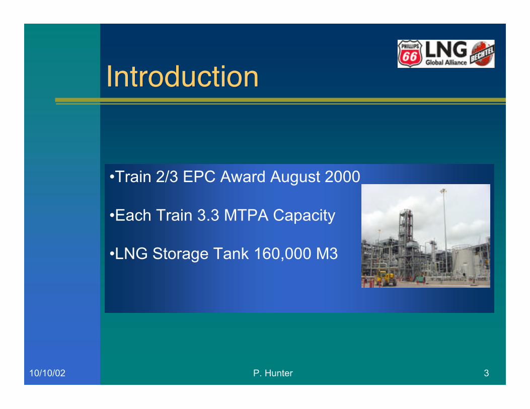
Inlet Area and Gas Treating
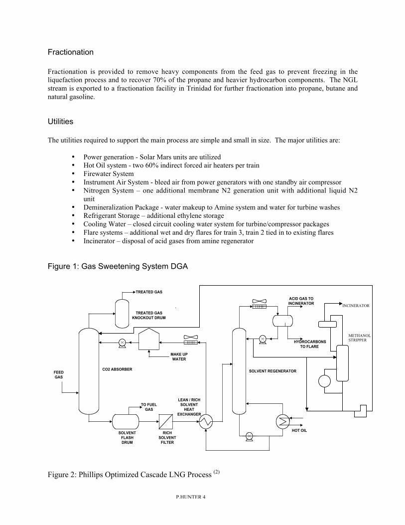
The Feed Gas to Trains 2/3 is from two sources. The BP feed gas enters the facility through the existingtrain 1 slug catcher where the vapor and liquid streams are separated. The liquid stream is stabilized intrain 1 and is exported offsite. The vapor stream is metered for allocation purposes prior to entering thetrain 1 and train 2 gas sweetening systems where the CO2 is removed. The BG feed gas enters the facilitythrough a new pig receiver and slug catcher before merging with the BP feed gas to comprise the totalfeed gas for train 2. The feed gas allocation split for train 2 is 50/50 for BP and BG feed supplies.Diglycolamine (DGA) is the selected solvent for the gas sweetening process due to low CO2/H2Sconcentrations in both feed gas streams and no other sulfur components. The acid gases, CO2/H2S andany incidentally removed hydrocarbon components, are safely disposed of by incineration. The BG gassupply has methanol injection into the pipeline and to remove any entrained methanol from the feed gasprior to sending it forward to the dehydration section a methanol stripper has been added to the overheadwater tray section of the CO2 system regenerator column that effectively removes the entrained methanolfrom the feed gas going forward. Treated gas from the amine system is fed to molecular sieve dehydratorswhere the water vapor is removed down to 0.1 ppm. Dry gas from the dehydrators is further processedthrough activated carbon beds to remove any mercury that may be in the feed gas.
Refrigeration and Liquefaction
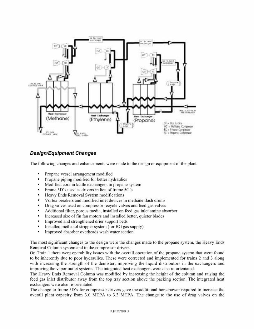
The treated gas is fed to the liquefaction unit where it is cooled and sub-cooled prior to entering the LNGtanks. The liquefaction system utilizes the Phillips Optimized Cascade LNG Process, a modification ofthe original Phillips LNG plant design at Kenai, Alaska. This process uses two pure refrigerants –propane and ethylene circuits and a methane flash circuit cascaded to provide maximum LNG productionby utilizing the horsepower available from 6 Frame 5D gas turbines. Each circuit uses two 50%compressors with common process equipment. The compressor and turbine packages are manufacturedby Nuovo Pignone of Florence, Italy. Brazed Aluminum Heat Exchangers and Core-in-Kettle Exchangersare used for the feed gas, propane, ethylene and methane circuits downstream of the mercury removalsystem. All of these heat exchangers with the exception of the propane chillers are housed in two “ColdBoxes”. These boxes are manufactured by Chart-Altec. All compressor inter-cooling, after-cooling andpropane refrigerant condensing is provided by fin-fan heat exchangers. The LNG from the last stage flashdrum is sent to the LNG tanks by the LNG transfer pumps where it is stored at approximately 70 mbarand –161 o C.
P.HUNTER 4
Fractionation
Fractionation is provided to remove heavy components from the feed gas to prevent freezing in theliquefaction process and to recover 70% of the propane and heavier hydrocarbon components. The NGLstream is exported to a fractionation facility in Trinidad for further fractionation into propane, butane andnatural gasoline.
Utilities
The utilities required to support the main process are simple and small in size. The major utilities are:
• Power generation - Solar Mars units are utilized• Hot Oil system - two 60% indirect forced air heaters per train• Firewater System• Instrument Air System - bleed air from power generators with one standby air compressor• Nitrogen System – one additional membrane N2 generation unit with additional liquid N2
unit• Demineralization Package - water makeup to Amine system and water for turbine washes• Refrigerant Storage – additional ethylene storage• Cooling Water – closed circuit cooling water system for turbine/compressor packages• Flare systems – additional wet and dry flares for train 3, train 2 tied in to existing flares• Incinerator – disposal of acid gases from amine regenerator
Figure 1: Gas Sweetening System DGA
FEEDGAS
TO FUELGAS
SOLVENTFLASHDRUM
RICHSOLVENT
FILTER
LEAN / RICHSOLVENT
HEATEXCHANGER
SOLVENT REGENERATOR
TREATED GASKNOCKOUT DRUM
CO2 ABSORBER
HOT OIL
ACID GAS TOINCINERATOR
HYDROCARBONSTO FLARE
MAKE UPWATER
TREATED GAS
Figure 2: Phillips Optimized Cascade LNG Process (2)
METHANOLSTRIPPER
INCINERATOR
P.HUNTER 5
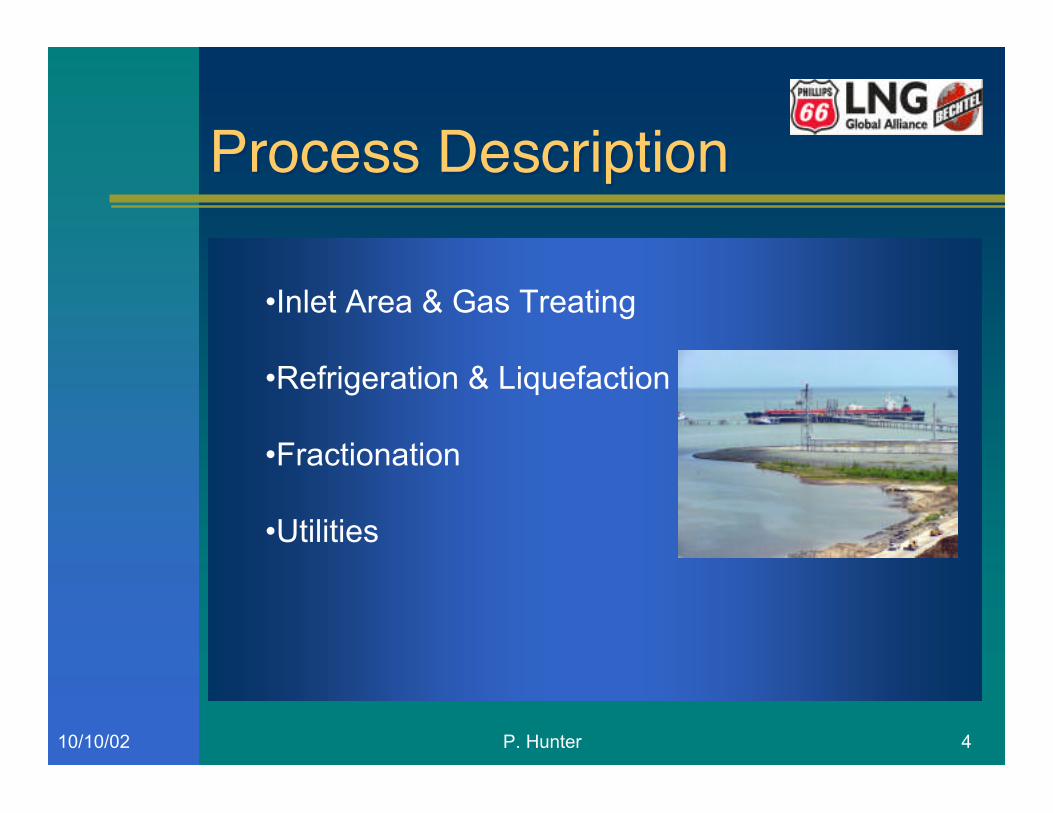
Design/Equipment Changes
The following changes and enhancements were made to the design or equipment of the plant.
• Propane vessel arrangement modified• Propane piping modified for better hydraulics• Modified core in kettle exchangers in propane system• Frame 5D’s used as drivers in lieu of frame 5C’s• Heavy Ends Removal System modifications• Vortex breakers and modified inlet devices in methane flash drums• Drag valves used on compressor recycle valves and feed gas valves• Additional filter, porous media, installed on feed gas inlet amine absorber• Increased size of fin fan motors and installed better, quieter blades• Improved and strengthened drier support beds• Installed methanol stripper system (for BG gas supply)• Improved absorber overheads wash water section
The most significant changes to the design were the changes made to the propane system, the Heavy EndsRemoval Column system and to the compressor drivers.On Train 1 there were operability issues with the overall operation of the propane system that were foundto be inherently due to poor hydraulics. These were corrected and implemented for trains 2 and 3 alongwith increasing the strength of the demister, improving the liquid distributors in the exchangers andimproving the vapor outlet systems. The integrated heat exchangers were also re-orientated.The Heavy Ends Removal Column was modified by increasing the height of the column and raising thefeed gas inlet distributor away from the top tray section above the packing section. The integrated heatexchangers were also re-orientatedThe change to frame 5D’s for compressor drivers gave the additional horsepower required to increase theoverall plant capacity from 3.0 MTPA to 3.3 MTPA. The change to the use of drag valves on the
P.HUNTER 6
compressor recycle systems improves operating stability as well as reducing noise when the machines areon recycle.A methanol stripping section was added to the overhead system of the CO2 system regenerator column toremove any entrained methanol from the main feed gas stream before it goes forward to the dryingsection. This addition is a requirement due to the injection of methanol in to the BG feed gas pipeline.The remaining changes were all done to improve the performance of the various sections based uponhistorical operating data from train 1.
Commissioning & Start-up
Operator Training
The seconded plant operations staff was supplied by Atlantic LNG sufficiently early in the project toensure vendor training could be provided prior to commissioning and start-up activities. The Bechtelsupplied operator training requirements for trains 2/3 consisted of a vendor training program only, asAtlantic LNG had performed the basic operator and maintenance training programs in-house prior to theirpersonnel being seconded to Bechtel.
Bechtel was responsible for establishing the vendor training program which consisted of training oncritical equipment such as Solar Power Generators, Nuovo Pignone Gas Turbines and Compressors, CCCControls, Bentley Nevada, Honeywell DCS, General Monitors for Fire & Gas and the PhillipsLiquefaction Technology.
The training program was held over a period of 6 weeks and was completed on schedule.
Milestones
Early work on the facility began in March 2000 with the EPC contract being awarded in August, 2000.Most of the utilities were commissioned by May 2002 to allow the introduction of the hydrocarbons intothe inlet area up to the pig receiver for supplying fuel gas to the power generators. Initial start of the newpower generators used fuel gas from train 1 until train 2 fuel systems were up and running. The new BGpipeline was commissioned in March 2002. The following outlines the major commissioning and startupmilestones:
• Power generators started up - March 2002.• Cooling water system started up – May 2002• Wet flare system started – June 2002• HP/LP Fuel gas systems started up - June 2002• Hot Oil system started up – June 2002• Perform Solo & Mechanical runs on Turbine/compressor packages – June 2002• Inlet area pressured up – July 2002• Amine system commissioned – July 2002• Startup molecular sieve dryers – July 2002• Dry out liquefaction process system – July 2002• Startup refrigeration compressors – August 2002• Cool down process – August 2002• Make LNG – August 7, 2002• Load 1st LNG Tanker – August 14, 2002• Complete Performance Test – October 3, 2002
P.HUNTER 7
Lessons Learned
During commissioning and start-up of the facilities a number of minor problems were encountered. Thenature and number of the problems was not inconsistent with those one might expect from a project ofthis size. Some of these problems are highlighted here.
• Compressor recycle valve positioner problems• Design problems on one vapor line
Despite these relatively few problems the start-up team was able to find and implement solutions andfinish the project ahead of schedule without compromising safety of the start-up or long term plantoperations. The value of these experiences will be realized when lessons learned as a result of knowledgegained are applied to design and operations improvements on the future trains and future projects.
AcceptanceTesting
The train 2/3 contract between Bechtel and Atlantic LNG was again ‘Turn Key” based upon the samemodel used for train 1. The principal difference being that for trains 2/3 Bechtel was required to supplyonly senior operating staff but still all maintenance, safety, technical support and supervisory personnelfor the safe start-up and initial operation of the plant until final performance tests had been successfullycompleted. Members of Atlantic LNG operations experienced staff became a part of the integrated teamand continued under Bechtel's direction to be the hands-on-operators during the commissioning and startup of the train. The same philosophy and approach will apply to train 3 also.
There were two types of acceptance tests that made up the plant performance requirements. These werecommissioning tests for individual equipment or units and an overall performance test of the operatingfacility.
Commissioning Tests (process and utility)
Commissioning tests were required for all systems, all package units, various special items such asmetering skids, firewater pumps, utility systems and of course, all control systems, alarm systems andshutdown systems. The purpose of the Commissioning tests was to demonstrate that individual systemswithin the facility performed according to design specifications within the EPC contract. There were 22individual tests each with a procedure and a report documenting the results and individually signed off byboth Bechtel and owner and witnessed by owner. All commissioning tests have to be completed beforePerformance Tests could begin.
Performance Test
A 72 hour performance test was conducted to prove the plant capacity, fuel efficiency and LPG recoveryrate. Additional loading capacity will be tested upon completion of the third LNG tank with train 3. Thistest is Bechtel's final deliverable required for contract completion and final turnover.Plant simulations under the exact conditions expected during the test have been done ahead of time todetermine the exact effects of site weather and possible variations in feed gas composition.
The 72 hour performance test of train 2 was successfully carried out beginning September 30, 2002 andthe following are the results from that test;
P.HUNTER 8
Performance Guarantee: 96% of PFD LNG productat ambient 26oCusing 93% refrigeration horsepower
Results achieved: 105% of PFD LNG productat a corrected 26oCusing 93% refrigeration horsepower
Future Expansion
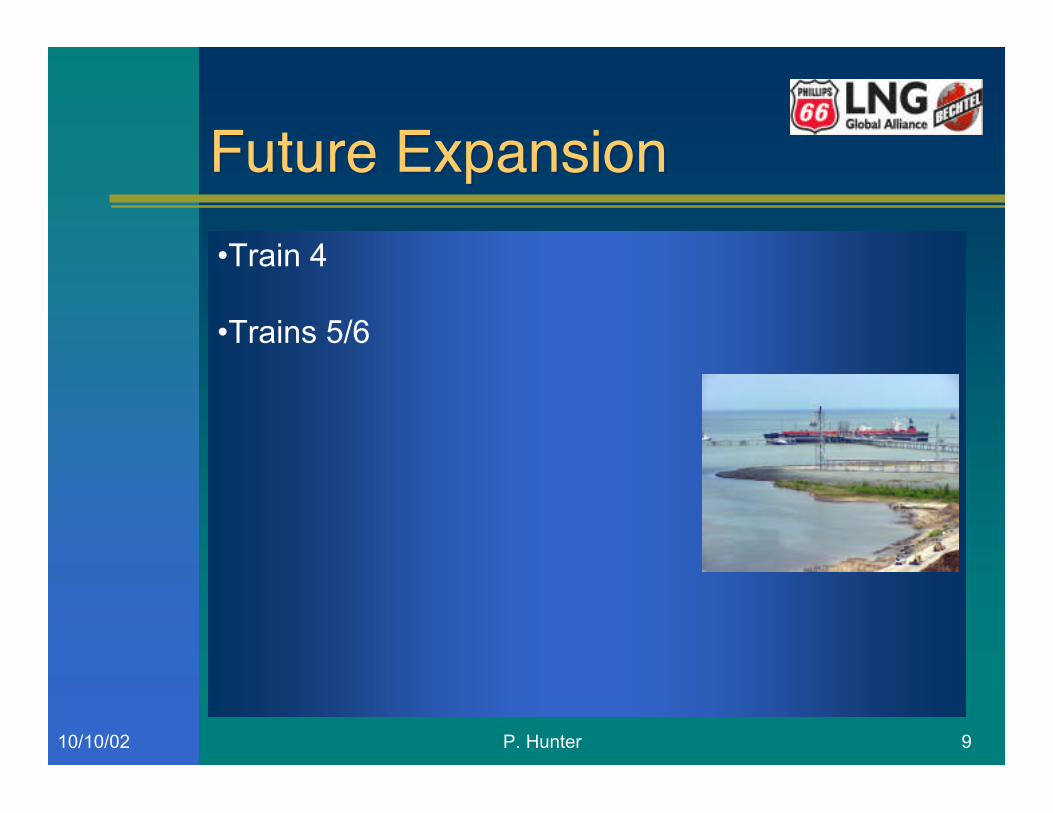
Atlantic LNG is committed to further expansion of the LNG facility at Point Fortin in Trinidad. Work hasalready begun on train 4 to further increase the production capacity of the facility. Train 4 will be basedupon the Phillips Optimized Cascade LNG Process and will continue with the use of frame 5D’s as theprimary driver for the refrigeration compressors. The plant capacity will be 4.8 MTPA bringing theoverall facility capacity to 14.7 MTPA. (Train 1 capacity is being increased from 3.0 MTPA to 3.3 MTPAwith an ongoing upgrade project)
Train 2 Acceleration
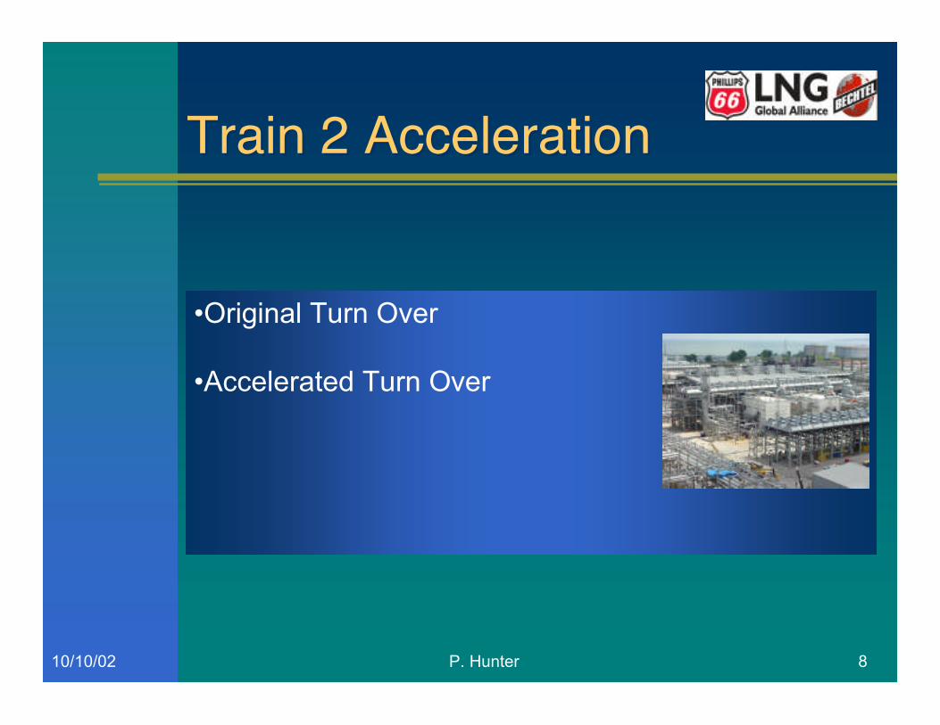
Regarding ALNG train 2, early in 2002 Bechtel were approached by Atlantic LNG and asked if there wasa possibility of accelerating the schedule to achieve earlier LNG production. The contractual turn over ofthe facility was December 15, 2002 and at the time of the request the forecast was showing a potentialturn over of November 5, 2002. It was agreed that best efforts would be made to try to achieve LNGproduction in early August 2002 and produce a volume of 87,000m3 of LNG shortly thereafter. Allefforts by Bechtel, Phillips and Atlantic LNG were focused on trying to achieve these targets. After anintense period of time beginning March 2002, LNG was produced on August 7, 2002 with an LNGvolume of 87,000m3 being produced by August 14, 2002. Once again the only way this was possible wasfor all parties to be a part of it, as on train 1, one team with no boundaries.
Reference:(1) “Passing the Baton Cleanly” – Gastech2000 –F.W.Richardson, P.Hunter, T.Diocee, J.Fisher
(2) Phillips Optimized Cascade LNG Process – W.R. Qualls/R. Martinez, ConocoPhillips 2001

P. Hunter 110/10/02
Trinidad LNG - "The SecondWave"
Trinidad LNG - "The SecondWave"Philip Hunter
Manager of LNG Technology & Start Up
Bechtel Petroleum & Chemicals Global Business Unit
Don Andress
LNG Licensing Group
ConocoPhillips

P. Hunter 210/10/02
“The Second Wave”“The Second Wave”
P. Hunter 310/10/02
•Train 2/3 EPC Award August 2000
•Each Train 3.3 MTPA Capacity
•LNG Storage Tank 160,000 M3
IntroductionIntroduction
P. Hunter 410/10/02
•Inlet Area & Gas Treating
•Refrigeration & Liquefaction
•Fractionation
•Utilities
Process DescriptionProcess Description

P. Hunter 510/10/02
Process Description (cont’d)Process Description (cont’d)
P. Hunter 610/10/02
•Propane suction drums•Propane piping•Propane demisters•Frame 5d’s•Heavy Ends Removal System•Methane Flash Drums•Compressor Anti Surge Valves•Feed Gas Filtration•Fin Fan Condensers/Coolers•Drier Bed Supports
Design/Equipment ChangesDesign/Equipment Changes
P. Hunter 710/10/02
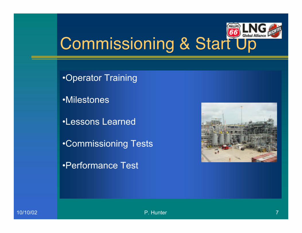
•Operator Training
•Milestones
•Lessons Learned
•Commissioning Tests
•Performance Test
Commissioning & Start UpCommissioning & Start Up
P. Hunter 810/10/02
•Original Turn Over
•Accelerated Turn Over
Train 2 AccelerationTrain 2 Acceleration
P. Hunter 910/10/02
•Train 4
•Trains 5/6
Future ExpansionFuture Expansion