Embed Size (px)
Citation preview
s
Answers for infrastructure and cities.
www.siemens.com/energy
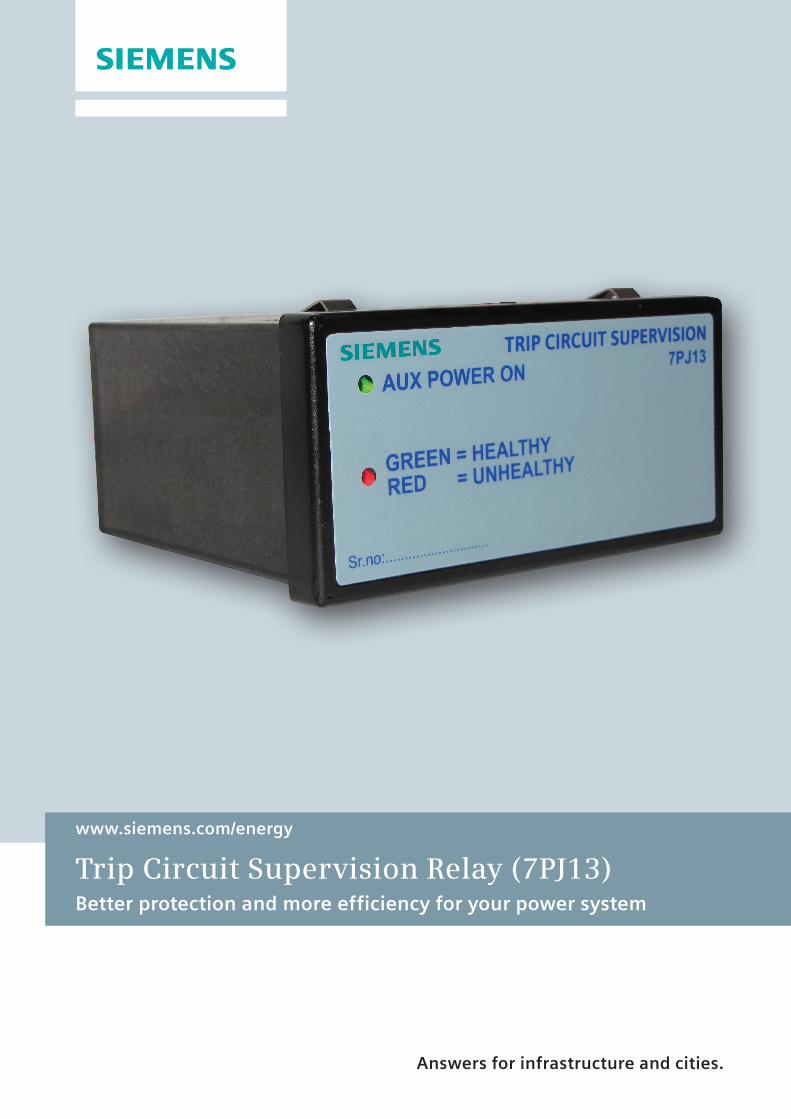
Trip Circuit Supervision Relay (7PJ13)Better protection and more efficiency for your power system

7PJ13
DescriptionTrip Circuit Supervision Relay is an electronic-circuit based relay which is used to monitor and supervise the integrity of circuit breaker’s trip coil and other wiring circuits of low-voltage and medium-voltage network. Trip Circuit Supervision Relay is connected with a circuit breaker to monitor the trip circuit positions (open or closed).
Trip Circuit Supervision Relay generates a trip circuit failure alarm, either if the trip circuit supply is disconnected or if the trip circuit connection is changed to an open circuit. Trip circuit continuity is measured by supplying the supervision
current of 0.7 mA to 1.5 mA and sensing the flow of current with two opto-couplers. The circuit breaker contact indicates the status of relay whether the circuit breaker is in open position or closed position.
The front panel of Trip Circuit Supervision Relay comprises of single LED with dual colored to indicate the status of process.
In a healthy condition, the Green LED flashes and the output relay reaches the pick-up condition. In the fault condition, the Red LED flashes and the output relay reaches the drop-off condition and operates after a delay of 500 ms.
FeaturesThe salient features of Trip Circuit Supervision Relay are:
Universal auxiliary voltage range with very low burden (i.e.) 24 V to 230 V AC/DC at less than 4 watts
Universal supervision voltage range (i.e.) 24 V to 230 V DC
Compact-in-size 48x96 mm
Fitted with flush-mounting
Continuous supervision of trip circuit in Pre-closed, Post-closed condition, and latched trip condition
Detects faults such as Auxiliary voltage loss and circuit breakage in supervised circuits
Indicates operational status by single LED with dual color
Relay has been type tested in accordance with IEC60255 standards
Figure 1.1 - Block diagram of Trip Circuit Supervision Relay
Trip Circuit Supervision Relay
2

Figure 1.2 - Supervision in pre-close condition Figure 1.4 - Supervision in latched trip condition
ApplicationsTrip Circuit Supervision Relay is used in the following field applications:
Used for monitoring activities. The trip circuit wiring is supervised from the positive supply to the negative supply when the circuit breaker is in open position or closed position.
Used for detecting and generating circuit breaker alarm, if the trip circuit supply is failed.
Used to generate an alarm if the trip signal is received but the circuit breaker fails to operate.
Mounting InstructionsTrip Circuit Supervision Relay comprises of all the mounting elements required for the mounting. To flush mount the Trip Circuit Supervision Relay, the following requirements should be satisfied:
Cut a hole in the panel with a measurement of 45mm x 92mm (HxW).
Carry out all the required internal wiring connections.
Flush Trip Circuit Supervision Relay into panel and lock with the clamps.
Supervision OperationTrip Circuit Supervision Relay contact operates in the following 3 supervision conditions:
Supervision in pre-close condition
After the tripping circuit is completed, a small amount of sensing current flows through TS1, TS2, circuit breaker auxiliary contacts (52b), and tripping coil. Trip Circuit Supervision Relay indicates a healthy condition by flashing the Green LED.
If the tripping circuit becomes an open circuit or loss of supply voltage, an unhealthy condition of Trip Circuit Supervision Relay is indicated by flashing Red LED and issue a control command by drop-off contacts.
Supervision in post-close condition
After the tripping circuit is completed, a small amount of sensing current flows through TS1, circuit breaker auxiliary contacts (52a) and tripping coil. Trip Circuit Supervision Relay indicates a healthy condition by flashing the Green LED.
If the tripping circuit becomes an open circuit or loss of supply voltage, the unhealthy condition of Trip Circuit Supervision Relay is indicated by flashing Red LED and issue a control command by drop-off contacts.
Figure 1.3 - Supervision in post-close condition
Supervision in latched trip condition
After the tripping circuit is completed, a small amount of sensing current flows through TS2, circuit breaker auxiliary contacts (52b) and tripping coil. Trip Circuit Supervision Relay indicates a healthy condition by flashing the Green LED.
If the tripping circuit becomes an open circuit or loss of supply voltage, the unhealthy condition of Trip Circuit Supervision Relay is indicated by flashing Red LED and issue a control command by drop-off contacts.
Trip Circuit Supervision Relay
3

MLFB (Ordering Code)Use the following ordering information to order Trip Circuit Supervision Relay.
7 P J 1 3 2 1 - 5 A A 2 1 - 0 A A 0
Variants Order Number
Relay Type
Trip Circuit Supervision Relay
Number of Binary Inputs
Element 2
Contact Reset Type
Self Reset
Auxiliary Voltage Range
24 V - 230 V DC/AC
Contact Arrangement - NO
0 NO
Contact Arrangement - NC
0 NC
Contact Arrangement - CO
2 CO
Binary Input Range
24 V - 230 V DC
3
2
1
5
A
A
2
1
Figure 1.5 - MLFB of Trip Circuit Supervision Relay
Terminal Diagram
Table 1-2 Binary terminals specification
Terminal number Terminal name Description
K2-(1) BI1 Binary Input 1-1
(2) BI1 Binary Input 1-2
(3) - -
(4) BI2 Binary Input 2-1
(5) BI2 Binary Input 2-2
(6) - -
(7) COM-1 Common
(8) NC-1 Normal Closed
(9) NO-1 Normal Open
(10) COM-2 Common
(11) NC-2 Normal Closed
(12) NO-2 Normal Open
The terminal diagram is located on the top of Trip Circuit Supervision Relay housing and displays the terminal numbers and terminals.
Figure 1.6 - Terminal Diagram of Trip Circuit Supervision Relay
Table 1-1 Auxiliary terminals specification
Terminal number Terminal name Description
K1-(1) +~ Auxiliary Voltage Positive
(2) - ~ Auxiliary Voltage Negative
(3) -
(4) E Earth
Trip Circuit Supervision Relay
4
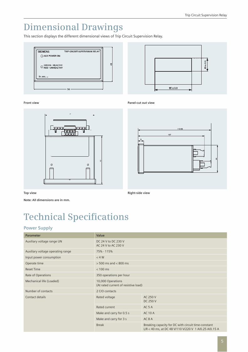
Front view
Top view
Note: All dimensions are in mm.
Panel-cut out view
Right-side view
Dimensional DrawingsThis section displays the different dimensional views of Trip Circuit Supervision Relay.
Technical SpecificationsPower Supply
Parameter Value
Auxiliary voltage range UN DC 24 V to DC 230 VAC 24 V to AC 230 V
Auxiliary voltage operating range 75% - 115%
Input power consumption < 4 W
Operate time > 500 ms and < 800 ms
Reset Time < 100 ms
Rate of Operations 350 operations per hour
Mechanical life (Loaded) 10,000 Operations (At rated current of resistive load)
Number of contacts 2 C/O contacts
Contact details Rated voltage AC 250 V DC 250 V
Rated current AC 5 A
Make and carry for 0.5 s AC 10 A
Make and carry for 3 s AC 8 A
Break Breaking capacity for DC with circuit time-constant L/R < 40 ms, at DC 48 V/110 V/220 V 1 A/0.25 A/0.15 A
Trip Circuit Supervision Relay
5
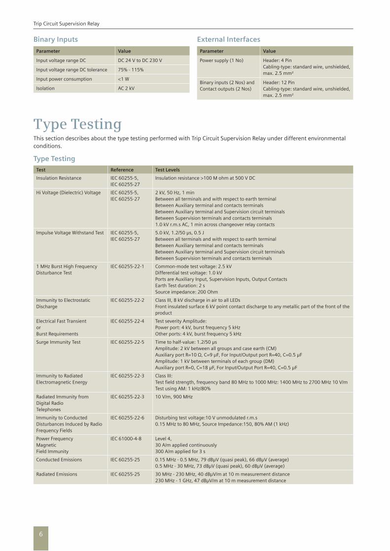
Binary Inputs
Parameter Value
Input voltage range DC DC 24 V to DC 230 V
Input voltage range DC tolerance 75% - 115%
Input power consumption <1 W
Isolation AC 2 kV
External Interfaces
Parameter Value
Power supply (1 No) Header: 4 PinCabling-type: standard wire, unshielded, max. 2.5 mm²
Binary inputs (2 Nos) and Contact outputs (2 Nos)
Header: 12 Pin Cabling-type: standard wire, unshielded, max. 2.5 mm²
Type TestingThis section describes about the type testing performed with Trip Circuit Supervision Relay under different environmental conditions.
Type Testing
Test Reference Test Levels
Insulation Resistance IEC 60255-5,IEC 60255-27
Insulation resistance >100 M ohm at 500 V DC
Hi Voltage (Dielectric) Voltage IEC 60255-5,IEC 60255-27
2 kV, 50 Hz, 1 minBetween all terminals and with respect to earth terminalBetween Auxiliary terminal and contacts terminalsBetween Auxiliary terminal and Supervision circuit terminalsBetween Supervision terminals and contacts terminals1.0 kV r.m.s AC, 1 min across changeover relay contacts
Impulse Voltage Withstand Test IEC 60255-5,IEC 60255-27
5.0 kV, 1.2/50 μs, 0.5 JBetween all terminals and with respect to earth terminalBetween Auxiliary terminal and contacts terminalsBetween Auxiliary terminal and Supervision circuit terminalsBetween Supervision terminals and contacts terminals
1 MHz Burst High Frequency Disturbance Test
IEC 60255-22-1 Common-mode test voltage: 2.5 kVDifferential test voltage: 1.0 kVPorts are Auxiliary Input, Supervision Inputs, Output ContactsEarth Test duration: 2 sSource impedance: 200 Ohm
Immunity to Electrostatic Discharge
IEC 60255-22-2 Class III, 8 kV discharge in air to all LEDsFront insulated surface 6 kV point contact discharge to any metallic part of the front of the product
Electrical Fast TransientorBurst Requirements
IEC 60255-22-4 Test severity Amplitude: Power port: 4 kV, burst frequency 5 kHzOther ports: 4 kV, burst frequency 5 kHz
Surge Immunity Test IEC 60255-22-5 Time to half-value: 1.2/50 μsAmplitude: 2 kV between all groups and case earth (CM)Auxiliary port R=10 Ω, C=9 μF, For Input/Output port R=40, C=0.5 μFAmplitude: 1 kV between terminals of each group (DM)Auxiliary port R=0, C=18 μF, For Input/Output Port R=40, C=0.5 μF
Immunity to Radiated Electromagnetic Energy
IEC 60255-22-3 Class III: Test field strength, frequency band 80 MHz to 1000 MHz: 1400 MHz to 2700 MHz 10 V/mTest using AM: 1 kHz/80%
Radiated Immunity fromDigital RadioTelephones
IEC 60255-22-3 10 V/m, 900 MHz
Immunity to Conducted Disturbances Induced by Radio Frequency Fields
IEC 60255-22-6 Disturbing test voltage:10 V unmodulated r.m.s 0.15 MHz to 80 MHz, Source Impedance:150, 80% AM (1 kHz)
Power FrequencyMagneticField Immunity
IEC 61000-4-8 Level 4,30 A/m applied continuously300 A/m applied for 3 s
Conducted Emissions IEC 60255-25 0.15 MHz - 0.5 MHz, 79 dBμV (quasi peak), 66 dBμV (average) 0.5 MHz - 30 MHz, 73 dBμV (quasi peak), 60 dBμV (average)
Radiated Emissions IEC 60255-25 30 MHz - 230 MHz, 40 dBμV/m at 10 m measurement distance 230 MHz - 1 GHz, 47 dBμV/m at 10 m measurement distance
Trip Circuit Supervision Relay
6
Test Reference Test Levels
Power Supply Test IEC 60255-11 Voltage Variations: 18 V - 265 VVoltage interruptions 18 V, 10 ms Voltage interruptions 110 V, 50 msRipple in DC voltage: Max 15% of DC valueGradual shutdown/start-up in auxiliary power supply voltageReversal of DC power supply polarity
Vibration Test IEC 60255-21-1 Response Class I, 10 Hz - 150 Hz, 0.5 g, 3 axis, Endurance Class I, 10 Hz - 150 Hz, 1.0 g, 3 axis
Shock and Bump IEC 60255-21-2 Shock response, Class I, 5 g, 11 ms Shock withstand, Class I, 15 g, 11 msBump Class I, 10 g, 16 ms
Seismic Test IEC 60255-21-3 In single axis sine sweep in X-axis sweep (@a sweep rate of 1 octave/min) vibration in the frequency range (5 Hz - 40 Hz) at amplitude of 3.5 mm or 1.0 gn (whichever is less) In single axis sine sweep in Y-axis sweep (@a sweep rate of 1 octave/min) vibration in the frequency range (5 Hz - 40 Hz) at amplitude of 1.5 mm or 0.5 gn (whichever is less)
Degree of Protection IEC 60529,IEC 60255-27
IP54 Front sideIP20 Rear Terminal side
Cold Test IEC 60068-2-1 -10°C, 96 hours
Dry Heat Test IEC 60068-2-2 +55°C, 96 hours
Storage Test IEC 60068-2-1, IEC 60068-2-2
-25°C to +70°C, 16 hours
Damp Heat Test, Cyclic IEC 60068-2-30 6 days at 95% RH and +40 ºC
Rated Burden of Auxiliary and Supervision Circuit
IEC60255-6 Auxiliary port burden at 24 V, 110 V, 220 V DC/AC Supervision port burden at 24 V, 110 V, 220 V DC/AC
Contact Performance at defined rate of operation
IEC60255-6 10,000 mechanical operations at the rate of 350 operations per hour
Contact Test IEC60255-23 Making capacity, Make and carry capacity, Breaking capacity
Product Safety Test as per IEC60255-27
Test Reference Test Levels
Clearances and Creepage Distances Test
Clearances and creepage distances between external circuits mutual and to the enclosure
≥ 4 mm
IP Rating For Unit Front sideFor Unit Rear Terminal side
IP54IP20
Impulse Voltage • Test voltage: 5 kV • Rise time/time to half-value: 1.2/50 μs • Output energy: 0.5 J
After test the relay should operate
AC or DC Dielectric Voltage • Test voltage between all live contacts and earth: 500 V DC • Test duration: > 5 s • Test voltage (AC): 2 kV • Test frequency: 50 Hz • Test duration: 1 min
After test the relay should operate
Insulation Resistance • Test voltage: 500 V DC• Test duration: > 5 s
> 100 Mohm
Protective Bonding Resistance • Test voltage: <12 V AC/DC • Test duration: 1 min • Bonding resistance
< 0.1 Ohm
Protective Bonding Continuity Accessible conductive parts should be bonded with the protective conductor terminal
Low current continuity test
Flammability of insulating materials, components and fire enclosures
• Terminals• Terminal Mounting• Wiring• Components Mounting• Enclosure
• IEC 60695-11-10, Class V-2, or Better• IEC 60695-11-10, Class V-1, or Better• IEC 60695-11-10, Class V-1, or Better• IEC 60695-11-10, Class V-2, or Better• IEC 60695-11-10, Class V-1, or Better
Single-fault Condition • Assessment of• Insulation between circuits and parts • Compliance with requirements for protection against the spread
of fire• Overloads• Intermittently rated resistors• Compliance with requirements for mechanical protection
The equipment shall not present a risk of electric shock or fire after a single-fault test
Trip Circuit Supervision Relay
7

C53000-X7076-C003-2(This replaces C53000-X7076-C003-1)
Customer Care Toll free no. 1800 419 7477Email: [email protected]
Product upgradation is a continuous process. Hence, data in this catalog is subject to change without prior notice. For the latest information, please get in touch with our Sales Offices.
Siemens Ltd.Infrastructure and Cities Sector Plot No. 6A, Sector 18, Maruti Industrial Area Huda, Gurgaon - 122 015, India. Tel.: +91 124 3836000, 3837362 Fax: +91 124 3836261
www.siemens.co.in
Regional Sales Offices
Support
NORTH - GurgaonSiemens Ltd. Infrastructure and Cities Sector 3rd Floor, Plot 6A, Sector 18 Maruti Industrial Area Gurgaon - 122015 Haryana, India Contact Person: Mr. I.K. Rai Tel. (Dir.): +91 124 4697376 Mobile: +91 9818018701 E-mail: [email protected] Mr. Vipul Lakhanpal Tel. (Dir.): +91 124 3837382 Mobile: +91 9555777491 E-mail: [email protected]
WEST - Mumbai Siemens Ltd. Infrastructure and Cities Sector Building 2, 1st Floor 130, Pandurang Budhakar Marg, Worli, Mumbai - 400018 Maharashtra, India Contact Person: Mr. Sachin Jaguste Tel. (Dir.): +91 22 39672353 Mobile: +91 9819155056 E-mail: [email protected] Mr. Vineet Garewal Tel. (Dir.): +91 22 39677578 Mobile: +91 9819155056 E-mail: [email protected]
Customer Support - Gurgaon Siemens Ltd. Infrastructure & Cities Sector Ground Floor, Plot 6A, Sector 18 Maruti Industrial Area Gurgaon - 122015 Haryana, India Ms. Yashasvi Sharma Tel. (Dir.): +91 124 3836415 E-mail: [email protected]
Technical Support - MumbaiSiemens Ltd. Infrastructure & Cities Sector Switchboard Building Thane Belapur Road, Thane - 400601 India Mr. Sagar Shaha Tel. (Dir.): +91 22 39663525 Mobile: +91 9820413204 E-mail: [email protected]
WEST - Vadodara Siemens Ltd. Infrastructure and Cities Sector Vishwakarma Bhavan Ground Floor, Maneja Works Vadodara - 390013 Gujarat, India Contact Person: Mr. Mandar Pagedar Tel. (Dir.): +91 265 3952131 Mobile: +91 9925004384 E-mail: [email protected]
EAST - Kolkata Siemens Ltd. Infrastructure and Cities Sector 43, Shantipalli Eastern Metropolitan Bypass R B connector, Kolkatta - 700042 West Bengal, India Contact Person: Mr. Amit Paul Tel. (Dir.): +91 33 30939313 Mobile: +91 9831130001 E-mail: [email protected] Mr. Manash Mahapatra Tel. (Dir.): +91 33 30939337 Mobile: +91 9903945156 E-mail: [email protected]
SOUTH - Chennai Siemens Ltd. Infrastructure and Cities Sector 4, Mahatma Gandhi Road Chennai (Madras) - 600034 Tamil Nadu, India Contact Person: Mr. Mudit Mehrotra Tel. (Dir.): +91 44 30474911 Mobile: +91 9790713479 E-mail: [email protected] Mr. Ponnusamy Nandakumar Tel. (Dir.): +91 44 30474281 Mobile: +91 9865055318 E-mail: [email protected]
For any Technical Documentation, Please visit the below URL
http://www.energy.siemens.com/hq/en/automation/power-transmission-distribution/protection/
For any general queries and technical support, please write to us at [email protected]
Siemens Ltd. Infrastructure and Cities sector Smart Grid IC-SG-EA-PRO Plot No. L-6, Verna Industrial Area Panaji-Margao Road Verna - 403722, Goa Tel.: +91 832 3993000 Fax: +91 832 6723299