Embed Size (px)
Citation preview
Triton EVM Getting Started Rev A02 : In Progress
Copyright Elevate Semiconductor 2012 Page 1 of 17
ISL55185 EVM Getting Started
Rev A02 : In Progress
This document contains information on a product under development. The parametric information contains target parameters that are subject to change.
Triton EVM Getting Started Rev A02 : In Progress
Copyright Elevate Semiconductor 2012 Page 2 of 17
Table of Contents
1 Introduction .......................................................................................................................................................... 4
1.1 Unpacking - ISL55185 EVM Contents ...................................................................................................... 4
1.2 Recommended Test and Measurement Setup ........................................................................................... 5 1.2.1 Power Supply ......................................................................................................................................... 5 1.2.2 PC Controller ......................................................................................................................................... 5 1.2.3 Test Equipment ...................................................................................................................................... 5
1.3 Software Installation ................................................................................................................................... 6 1.3.1 ISL55185 EVM UIP Installation ........................................................................................................... 6 1.3.2 Parallel Port (ParPort2K) Installation .................................................................................................... 6 1.3.3 Reboot Machine ..................................................................................................................................... 6 1.3.4 Launching the Elevate Semiconductor Program .................................................................................... 6 1.3.5 Software Un-Installation ........................................................................................................................ 6
2 Getting Started ...................................................................................................................................................... 7
2.1 Quick Start Instructions .............................................................................................................................. 7
2.2 Default Configuration Setup Options ........................................................................................................ 8 2.2.1 PMU Force Voltage and Active Load .................................................................................................... 8
2.3 ISL55185 EVM Jumper Definitions ........................................................................................................... 9
2.4 Motherboard Jumper and SMA Definition ............................................................................................... 9
2.5 ISL55185 EVM Menu Dialog Boxes ......................................................................................................... 11
3 Detailed Hardware Description .......................................................................................................................... 12
3.1 ISL55185 EVM Loadboard Detailed Description ................................................................................... 13
3.2 Capacitor and Resistor Network Definitions ........................................................................................... 14
3.3 ADC and Analog Mux ............................................................................................................................... 15
3.4 ISL55185 EVM Loadboard Controller .................................................................................................... 16
4 Document Revision History ................................................................................................................................ 17 List of Figures Figure 1: Installation Directory Structure ...................................................................................................... 6 Figure 2: Expected Current Readings .......................................................................................................... 7 Figure 3: PMU FV Block Diagram ................................................................................................................ 8 Figure 4: Device Config Menu Options ...................................................................................................... 11 Figure 5: Elevate Semiconductor EVM Overview Block Diagram ............................................................. 12 Figure 6: ISL55185 EVM Loadboard Detailed Block Diagram ................................................................... 13 Figure 7: ISL55185 EVM Capacitor/Resistor Network Block Diagram ...................................................... 14 Figure 8: Controller Section Detailed Block Diagram ................................................................................ 16 List of Tables Table 1: ISL55185 EVM Contents ................................................................................................................ 4 Table 2: Power Supply Requirements ......................................................................................................... 5 Table 3: ISL55185 Default Configuration Options ....................................................................................... 8 Table 4: ISL55185 EVM Jumper Definitions ................................................................................................ 9 Table 5: TC# Resource Allocation ............................................................................................................. 10 Table 6: Capacitor Network Definitions ...................................................................................................... 14
Triton EVM Getting Started Rev A02 : In Progress
Copyright Elevate Semiconductor 2012 Page 3 of 17
Table 7: ISL55185 EVM Resistor Network Definitions .............................................................................. 14 Table 8: FVMI Analog Mux – VINPOS(A) & VINNEG(A) Mapping ............................................................. 15 Table 9: ISL55185 EVM Loadboard Analog Mux Definitions – LB_AMUX Mapping ................................. 15
Triton EVM Getting Started Rev A02 : In Progress
Copyright Elevate Semiconductor 2012 Page 4 of 17
1 Introduction
Congratulations on your purchase of a Elevate Semiconductor ISL55185 EVM evaluation system. You will find that it serves as an invaluable development platform to help get your product to market in the shortest possible time. The ISL55185 EVM and Graphical User Interface (GUI) allow the customer to demonstrate and evaluate the ISL55185 performance and functionality. This document provides the instructions to install, setup, and operate the ISL55185 EVM. Refer to the Elevate Semiconductor EVM User’s Guide for a detailed description of the FVMI and Motherboard.
1.1 Unpacking - ISL55185 EVM Contents
Please check the contents of the ISL55185 EVM shipping carton to make sure you have received all of the items listed in Table 1. The system is already configured for the best setup, except for connections to the power supply, PC controller, and test equipment.
Table 1: ISL55185 EVM Contents
Qty Description 1 ea. ISL55185 EVM System (3 boards: Loadboard, EVM Motherboard, Octal
FVMI) 1 ea. ISL55185 EVM Getting Started (this document) 1 ea. Elevate Semiconductor User Interface Program Installation CD 1 ea. DB25M-DB25M, 6 Foot Parallel Port Cable
Triton EVM Getting Started Rev A02 : In Progress
Copyright Elevate Semiconductor 2012 Page 5 of 17
1.2 Recommended Test and Measurement Setup
1.2.1 Power Supply Table 2 provides the required power supplies and current rating. The power supplies are connected using standard banana plugs. The customer needs to provide the power supply cables. It is recommended to use a triple supply to control the EVM supplies. This allows the 3 EVM supplies to be turned on at the same time. However, if this is not feasible, then the supplies should be enabled in the following sequence. Power down should be performed in the reverse order.
1. +20V 2. -15V 3. +5V
The ISL55185 VCC and VEE are gated using an Opto-FET switch on the loadboard so it is safe to set and enable the ISL55185 VCC/VEE voltages before powering up the EVM and running the software.
Table 2: Power Supply Requirements
Module Supply Current Rating EVM +20V (1) 1.0 A EVM +5V 0.5 A EVM -15V 0.5 A ISL55185 VCC (4) +10V (2, 3) 0.5 A ISL55185 VEE (4) -5V (2, 3) 0.5 A
1) The EVM +20V could also be used as the ISL55185 VCC 2) The ISL55185 VCC – VEE voltage should not exceed 32V. Refer to the ABS max section in the
datasheet. 3) Once the EVM operation is verified, the customer can adjust the VCC/VEE supplies. 4) There is a provision to use the FVMI LT1206 to source the VCC/VEE supplies; this is controlled
by the E2/E3 Jumpers on the loadboard. The LT1206 can support +15V/-10V. The EVM GUI software V3.9.x does not support the option where the FVMI LT1206 is used to source the VCC/VEE supplies so an external power supply must be used.
1.2.2 PC Controller To use the ISL55185 EVM User Interface Program (UIP), a PC with the following configuration is required: Win98, Win2000, WinNT 4.0+, or Win XP Parallel/Printer Port – 25-pin female connector
1.2.3 Test Equipment Voltage and/or Current Meter Voltage and/or Current Source
Triton EVM Getting Started Rev A02 : In Progress
Copyright Elevate Semiconductor 2012 Page 6 of 17
1.3 Software Installation
There are 2 steps to install the ISL55185 EVM demonstration program. 1. Install the ISL55185 EVM UIP from the CD-ROM. 2. Install the parallel port driver (ParPort2k).
Figure 1 illustrates the default directory structure. The user may change the <root dir> during the installation.
Figure 1: Installation Directory Structure
<Root Dir>\Planet ATE\EVM\\DocumentsEVM GUI
\ParPort2k
1.3.1 ISL55185 EVM UIP Installation To install the ISL55185 EVM software package, run the SETUP program on the distribution CD and follow the prompts. The PlanetATE.exe executable will be installed in the EVM GUI sub-directory. In addition, a short cut will be installed onto the desktop and in the Start->Programs folder. The Start->Programs folder also contains links to the different product datasheets, EVM User’s Guide, and documentation folder.
1.3.2 Parallel Port (ParPort2K) Installation To install the ParPort2K parallel port driver, run the setup.exe from the ParPort2k sub-directory after the main installation is complete and click the Install button. For WinNT users, the user must have administration rights. Note: ParPort2k is a copyright of Zeecube Software.
1.3.3 Reboot Machine After the ISL55185 EVM and Parallel Port software is installed, it is recommended to re-boot the machine.
1.3.4 Launching the Elevate Semiconductor Program The user can launch the Elevate Semiconductor GUI from the desktop, Start->Programs folder, or EVM GUI sub-directory.
1.3.5 Software Un-Installation The Elevate Semiconductor demonstration program may be un-installed using the Add/Remove Program from the Windows Control Panel.
Triton EVM Getting Started Rev A02 : In Progress
Copyright Elevate Semiconductor 2012 Page 7 of 17
2 Getting Started
The ISL55185 EVM is shipped in a pre-configured state that allows a customer to evaluate the different modes. Note: Any external equipment providing digital signals into the ISL55185 device should only be enabled after the ISL55185 EVM is enabled. Also, the external equipment should be disabled prior to disabling the ISL55185 EVM.
2.1 Quick Start Instructions
1. Disable external power supplies 2. Connect the power supplies cables (not provided) from the power supply to the Elevate
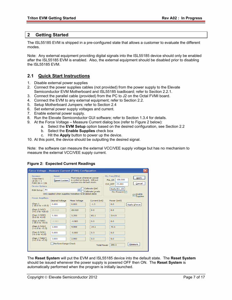
Semiconductor EVM Motherboard and ISL55185 loadboard; refer to Section 2.2.1. 3. Connect the parallel cable (provided) from the PC to J2 on the Octal FVMI board. 4. Connect the EVM to any external equipment; refer to Section 2.2. 5. Setup Motherboard Jumpers; refer to Section 2.4 6. Set external power supply voltages and current. 7. Enable external power supply. 8. Run the Elevate Semiconductor GUI software; refer to Section 1.3.4 for details. 9. At the Force Voltage – Measure Current dialog box (refer to Figure 2 below):
a. Select the EVM Setup option based on the desired configuration, see Section 2.2 b. Select the Enable Supplies check box c. Hit the Apply button to power up the device.
10. At this point, the device should be outputting the desired signal. Note: the software can measure the external VCC/VEE supply voltage but has no mechanism to measure the external VCC/VEE supply current.
Figure 2: Expected Current Readings
The Reset System will put the EVM and ISL55185 device into the default state. The Reset System should be issued whenever the power supply is powered OFF then ON. The Reset System is automatically performed when the program is initially launched.
Triton EVM Getting Started Rev A02 : In Progress
Copyright Elevate Semiconductor 2012 Page 8 of 17
2.2 Default Configuration Setup Options
The EVM has several default options for configuring for device into different modes.
Table 3: ISL55185 Default Configuration Options
Mode See Section # Brief Description Hardware Reset N/A All registers default to the hardware default state. Three-State (High-Z) N/A Puts device in three-state (high-Z). Opens all switches. FV (Force Voltage) 2.2.1 Configures all 8 channels to output 3.0V
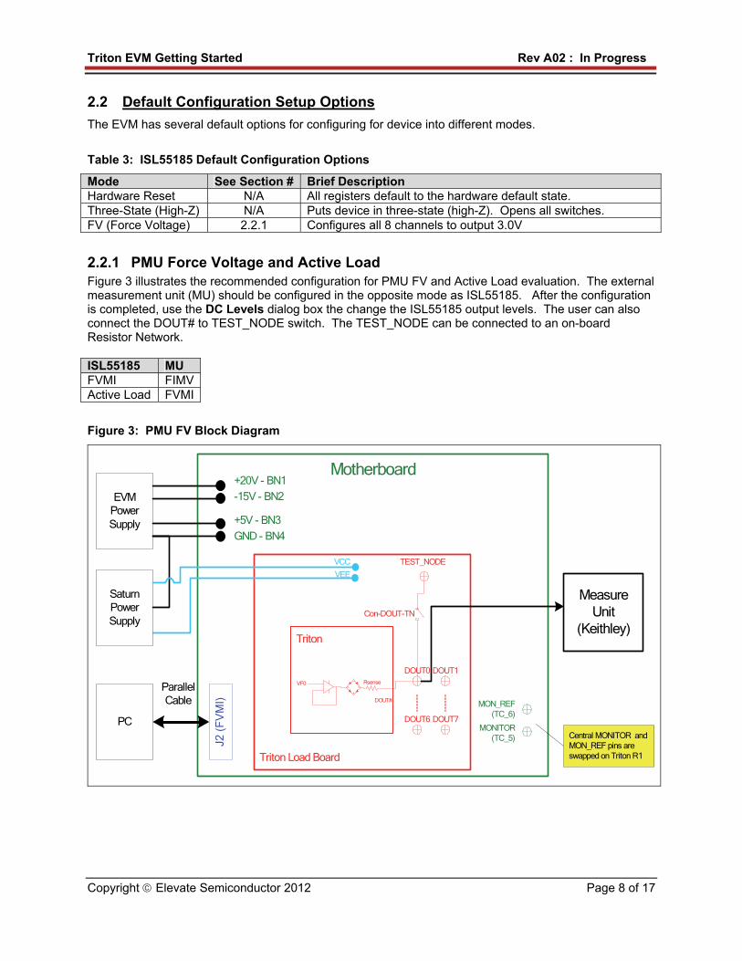
2.2.1 PMU Force Voltage and Active Load Figure 3 illustrates the recommended configuration for PMU FV and Active Load evaluation. The external measurement unit (MU) should be configured in the opposite mode as ISL55185. After the configuration is completed, use the DC Levels dialog box the change the ISL55185 output levels. The user can also connect the DOUT# to TEST_NODE switch. The TEST_NODE can be connected to an on-board Resistor Network. ISL55185 MU FVMI FIMV Active Load FVMI
Figure 3: PMU FV Block Diagram
Motherboard
Triton Load Board
PC
J2 (
FV
MI)
ParallelCable
EVMPowerSupply
+20V - BN1
+5V - BN3
-15V - BN2
GND - BN4
VEE
VCC
Triton
DOUT0VF0
MeasureUnit
(Keithley)
DOUT#
MONITOR(TC_5)
MON_REF(TC_6)
TEST_NODE
SaturnPowerSupply
Con-DOUT-TN
Rsense
DOUT1
DOUT6 DOUT7
Central MONITOR and MON_REF pins are swapped on Triton R1
Triton EVM Getting Started Rev A02 : In Progress
Copyright Elevate Semiconductor 2012 Page 9 of 17
2.3 ISL55185 EVM Jumper Definitions
Table 4 lists the ISL55185 EVM Jumper definitions.
Table 4: ISL55185 EVM Jumper Definitions
Jumper Description Configuration E1 Connect VFORCE Installed E2 VCC Source Short Pin 1 & 2. Towards back of board E3 VEE Source Short Pin 1 & 2. Towards back of board
Note: The EVM GUI software V3.9.x does not support the option where the FVMI LT1206 is used to source the VCC/VEE supplies. An external power supply must be used.
2.4 Motherboard Jumper and SMA Definition
Table 5 lists the Tester Channel (TC_#) connector definitions for the ISL55185 EVM Loadboard. On the EVM Motherboard, most of the TC_# signals can be connected to an SMA. In addition, some TC_# signals (digital inputs) go through a 3-pin jumper to allow the inputs to be sourced from either the SMA or a latch.
Triton EVM Getting Started Rev A02 : In Progress
Copyright Elevate Semiconductor 2012 Page 10 of 17
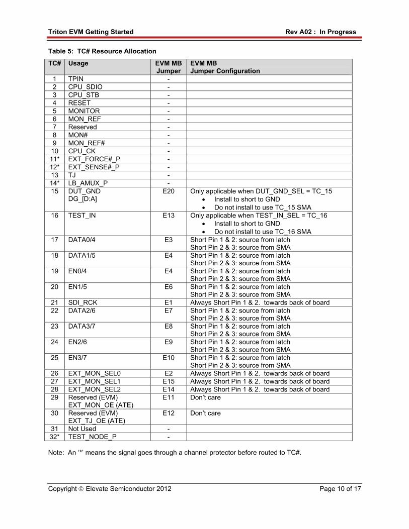
Table 5: TC# Resource Allocation
TC# Usage EVM MB Jumper
EVM MB Jumper Configuration
1 TPIN - 2 CPU_SDIO - 3 CPU_STB - 4 RESET - 5 MONITOR - 6 MON_REF - 7 Reserved - 8 MON# - 9 MON_REF# - 10 CPU_CK - 11* EXT_FORCE#_P - 12* EXT_SENSE#_P - 13 TJ - 14* LB_AMUX_P - 15 DUT_GND
DG_[D:A] E20 Only applicable when DUT_GND_SEL = TC_15
Install to short to GND Do not install to use TC_15 SMA
16 TEST_IN E13 Only applicable when TEST_IN_SEL = TC_16 Install to short to GND Do not install to use TC_16 SMA
17 DATA0/4 E3 Short Pin 1 & 2: source from latch Short Pin 2 & 3: source from SMA
18 DATA1/5 E4 Short Pin 1 & 2: source from latch Short Pin 2 & 3: source from SMA
19 EN0/4 E4 Short Pin 1 & 2: source from latch Short Pin 2 & 3: source from SMA
20 EN1/5 E6 Short Pin 1 & 2: source from latch Short Pin 2 & 3: source from SMA
21 SDI_RCK E1 Always Short Pin 1 & 2. towards back of board 22 DATA2/6 E7 Short Pin 1 & 2: source from latch
Short Pin 2 & 3: source from SMA 23 DATA3/7 E8 Short Pin 1 & 2: source from latch
Short Pin 2 & 3: source from SMA 24 EN2/6 E9 Short Pin 1 & 2: source from latch
Short Pin 2 & 3: source from SMA 25 EN3/7 E10 Short Pin 1 & 2: source from latch
Short Pin 2 & 3: source from SMA 26 EXT_MON_SEL0 E2 Always Short Pin 1 & 2. towards back of board 27 EXT_MON_SEL1 E15 Always Short Pin 1 & 2. towards back of board 28 EXT_MON_SEL2 E14 Always Short Pin 1 & 2. towards back of board 29 Reserved (EVM)
EXT_MON_OE (ATE) E11 Don’t care
30 Reserved (EVM) EXT_TJ_OE (ATE)
E12 Don’t care
31 Not Used - 32* TEST_NODE_P - Note: An ‘*’ means the signal goes through a channel protector before routed to TC#.
Triton EVM Getting Started Rev A02 : In Progress
Copyright Elevate Semiconductor 2012 Page 11 of 17
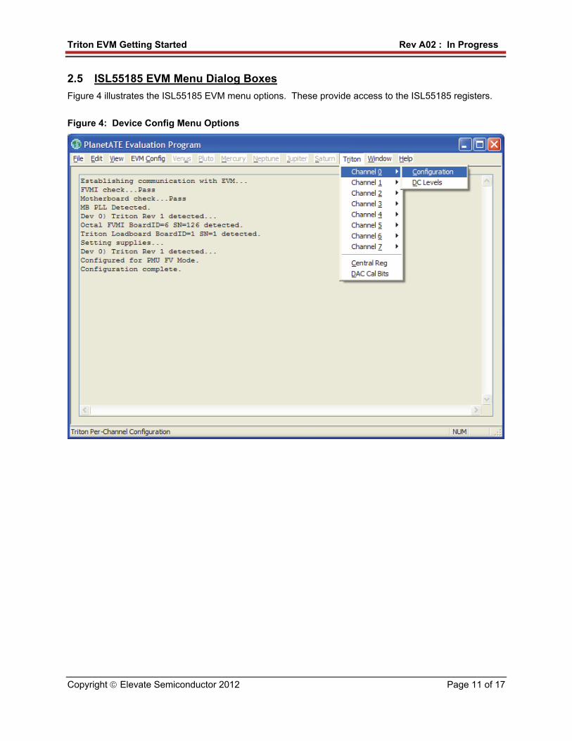
2.5 ISL55185 EVM Menu Dialog Boxes
Figure 4 illustrates the ISL55185 EVM menu options. These provide access to the ISL55185 registers.
Figure 4: Device Config Menu Options
Triton EVM Getting Started Rev A02 : In Progress
Copyright Elevate Semiconductor 2012 Page 12 of 17
3 Detailed Hardware Description
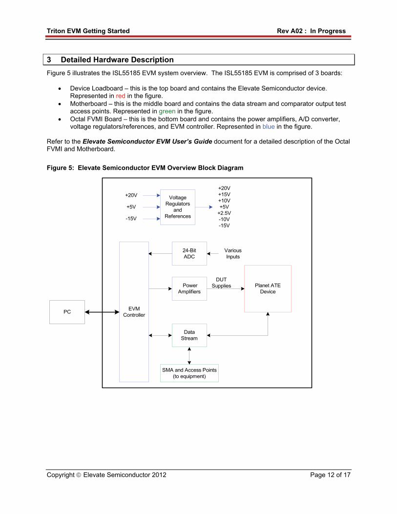
Figure 5 illustrates the ISL55185 EVM system overview. The ISL55185 EVM is comprised of 3 boards:
Device Loadboard – this is the top board and contains the Elevate Semiconductor device. Represented in red in the figure.
Motherboard – this is the middle board and contains the data stream and comparator output test access points. Represented in green in the figure.
Octal FVMI Board – this is the bottom board and contains the power amplifiers, A/D converter, voltage regulators/references, and EVM controller. Represented in blue in the figure.
Refer to the Elevate Semiconductor EVM User’s Guide document for a detailed description of the Octal FVMI and Motherboard.
Figure 5: Elevate Semiconductor EVM Overview Block Diagram
VoltageRegulators
andReferences
+20V
+5V
-15V
+20V+15V+10V+5V
+2.5V-10V-15V
PowerAmplifiers
VariousInputs
24-BitADC
EVMController
DUTSupplies Planet ATE
Device
DataStream
PC
SMA and Access Points(to equipment)
Triton EVM Getting Started Rev A02 : In Progress
Copyright Elevate Semiconductor 2012 Page 13 of 17
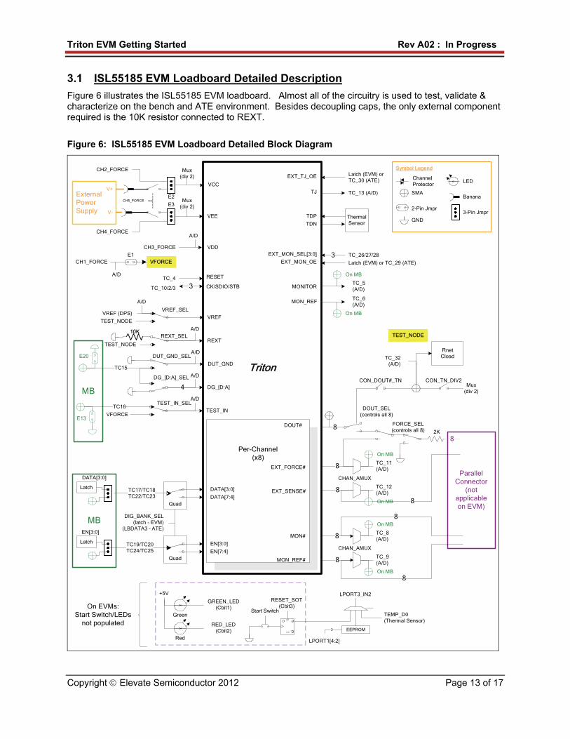
3.1 ISL55185 EVM Loadboard Detailed Description
Figure 6 illustrates the ISL55185 EVM loadboard. Almost all of the circuitry is used to test, validate & characterize on the bench and ATE environment. Besides decoupling caps, the only external component required is the 10K resistor connected to REXT.
Figure 6: ISL55185 EVM Loadboard Detailed Block Diagram
MB
Triton
Per-Channel(x8)
ParallelConnector
(not applicable on EVM)Quad
VFORCE
TEST_NODE
MB
CK/SDIO/STB
RESET
3
TC17/TC18TC22/TC23
Latch
DATA[3:0]
DATA[3:0] 8
MONITOR
EXT_SENSE#
EXT_FORCE#
VREF
VREF_SELVREF (DPS)
TEST_NODE
TC_10/2/3
TC_4
DUT_GNDTC15
VDDCH3_FORCE
E1CH1_FORCE
A/D
VCC
ExternalPowerSupply
VEE
V+
10K
Latch
EN[3:0]
DOUT#
TDP
TDN
MON_REF
CON_TN_DIV2Mux
(div 2)
A/D
Mux (div 2)
Mux (div 2)
Start Switch
Q
QSET
CLR
D
LPORT3_IN2
Red
Green
GREEN_LED(Cbit1)
RESET_SOT(Cbit3)
RED_LED(Cbit2)
+5V
EEPROM3
LPORT1[4:2]
On EVMs:Start Switch/LEDs
not populated
ChannelProtector
SMA
2-Pin Jmpr
GND
3-Pin Jmpr
Banana
LED
Symbol Legend
RnetCload
REXTREXT_SEL
TEST_NODE
A/D
A/D
A/D
DATA[7:4]
Quad
EN[3:0]
EN[7:4]
DIG_BANK_SEL(latch - EVM)
(LBDATA3 – ATE)
TC19/TC20TC24/TC25
ThermalSensor
8
8
TC_11(A/D)8
TC_12(A/D)
MON# 8
MON_REF# 8 TC_9(A/D)
TC_8(A/D)
8
8
8
TEMP_D0(Thermal Sensor)
DOUT_SEL(controls all 8)
CON_DOUT#_TN
EXT_MON_SEL[3:0]
EXT_MON_OE3 TC_26/27/28
Latch (EVM) or TC_29 (ATE)
TC_32(A/D)
TEST_IN
TEST_IN_SELTC16
A/D
VFORCE
TC_6(A/D)
TC_5(A/D)
On MB
On MB
On MB
On MB
On MB
On MB
DUT_GND_SEL
E13
E20
EXT_TJ_OE
TJ
Latch (EVM) orTC_30 (ATE)
TC_13 (A/D)
CH2_FORCE
V-
CH4_FORCE
CH5_FORCEE2
E3
FORCE_SEL(controls all 8) 2K
DG_[D:A]4
A/DDG_[D:A]_SEL
CHAN_AMUX
CHAN_AMUX
Triton EVM Getting Started Rev A02 : In Progress
Copyright Elevate Semiconductor 2012 Page 14 of 17
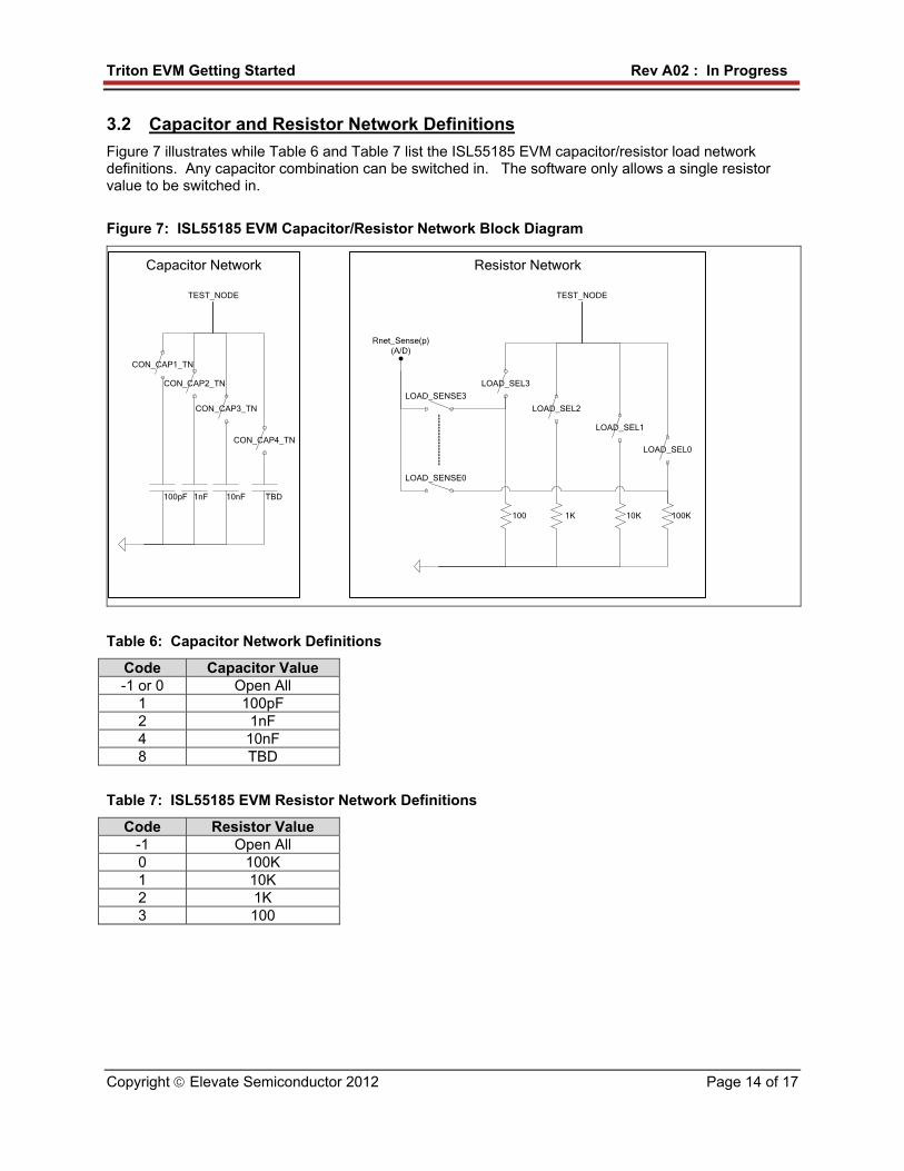
3.2 Capacitor and Resistor Network Definitions
Figure 7 illustrates while Table 6 and Table 7 list the ISL55185 EVM capacitor/resistor load network definitions. Any capacitor combination can be switched in. The software only allows a single resistor value to be switched in.
Figure 7: ISL55185 EVM Capacitor/Resistor Network Block Diagram
Capacitor Network Resistor Network
100K100
LOAD_SEL3
LOAD_SEL0
LOAD_SENSE0
LOAD_SENSE3
TEST_NODE
100pF
CON_CAP1_TN
1nF
CON_CAP2_TN
10nF
CON_CAP3_TN
TEST_NODE
1K
LOAD_SEL2
10K
LOAD_SEL1
TBD
CON_CAP4_TN
Rnet_Sense(p)(A/D)
Table 6: Capacitor Network Definitions
Code Capacitor Value -1 or 0 Open All
1 100pF 2 1nF 4 10nF 8 TBD
Table 7: ISL55185 EVM Resistor Network Definitions
Code Resistor Value -1 Open All 0 100K 1 10K 2 1K 3 100
Triton EVM Getting Started Rev A02 : In Progress
Copyright Elevate Semiconductor 2012 Page 15 of 17
3.3 ADC and Analog Mux
The Octal FVMI contains a 24-bit ADC and analog muxes which allows for the accurate measurement of many device and system voltages. Table 8 lists the ISL55185 EVM loadboard specific mux input sources. Table 9 lists the ISL55185 EVM loadboard AMUX_OUT analog mux which is routed to the TC-28 and VINN10 nodes. Notes:
1) Signals that have a ‘_P’ appended to the end of the name implies the signal goes through a channel protector or voltage dividers (i.e. VCC) since they could exceed the motherboard supplies (+20V/-15V).
2) VINP13 and VINP14 are connected to TC_31 and TC_32 on the motherboard.
Table 8: FVMI Analog Mux – VINPOS(A) & VINNEG(A) Mapping
Addr VINP# VINPOS(A) VINN# VINNEG(A) 7 VINP8 Reserved VINN8 VREF 8 VINP9 MON# (per-chan) VINN9 MON_REF# (per-chan) 9 VINP10 LB_AMUX_P (see below) VINN10 LB_AMUX_P (see below) 10 VINP11 MONITOR (Central) VINN11 MON_REF (Central) 11 VINP12 REXT VINN12 12 VINP13 TC_31 VINN13 13 VINP14 TC_32 (TEST_NODE_P) VINN14
Table 9: ISL55185 EVM Loadboard Analog Mux Definitions – LB_AMUX Mapping
Addr NO# LB_AMUX 0 1 DUT_GND 1 2 DG_A 2 3 DG_B 3 4 DG_C 4 5 DG_D 5 6 TN_DIV 6 7 VCC_DIV 7 8 VEE_DIV 8 9 EXT_FORCE# 9 10 EXT_SENSE# 10 11 TJ 11 12 TEST_IN 12 13 SENSE_RNET0 13 14 SENSE_RNET1 14 15 SENSE_RNET2 15 16 SENSE_RNET3
Triton EVM Getting Started Rev A02 : In Progress
Copyright Elevate Semiconductor 2012 Page 16 of 17
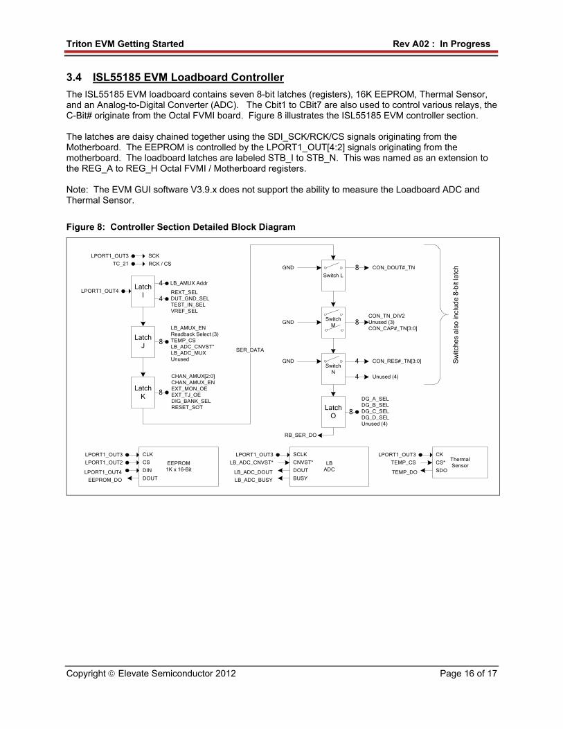
3.4 ISL55185 EVM Loadboard Controller
The ISL55185 EVM loadboard contains seven 8-bit latches (registers), 16K EEPROM, Thermal Sensor, and an Analog-to-Digital Converter (ADC). The Cbit1 to CBit7 are also used to control various relays, the C-Bit# originate from the Octal FVMI board. Figure 8 illustrates the ISL55185 EVM controller section. The latches are daisy chained together using the SDI_SCK/RCK/CS signals originating from the Motherboard. The EEPROM is controlled by the LPORT1_OUT[4:2] signals originating from the motherboard. The loadboard latches are labeled STB_I to STB_N. This was named as an extension to the REG_A to REG_H Octal FVMI / Motherboard registers. Note: The EVM GUI software V3.9.x does not support the ability to measure the Loadboard ADC and Thermal Sensor.
Figure 8: Controller Section Detailed Block Diagram
LatchI
4 LB_AMUX Addr
4REXT_SELDUT_GND_SELTEST_IN_SELVREF_SEL
LatchJ
8
LB_AMUX_ENReadback Select (3)TEMP_CSLB_ADC_CNVST*LB_ADC_MUXUnused
LatchK
8
CHAN_AMUX[2:0]CHAN_AMUX_ENEXT_MON_OEEXT_TJ_OEDIG_BANK_SELRESET_SOT
LPORT1_OUT4
Switch L
GND 8 CON_DOUT#_TN
4
SER_DATA
Sw
itche
s al
so in
clud
e 8-
bit l
atch
CON_RES#_TN[3:0]
Switch M
4 Unused (4)
Switch N
GND 8CON_TN_DIV2Unused (3)CON_CAP#_TN[3:0]
GND
ThermalSensor
LPORT1_OUT3 CK
CS*
SDO
TEMP_CS
TEMP_DO
LBADC
LPORT1_OUT3 SCLK
CNVST*
DOUT
BUSY
LB_ADC_CNVST*
LB_ADC_DOUT
LB_ADC_BUSY
EEPROM1K x 16-Bit
LPORT1_OUT3 CLK
CS
DIN
DOUT
LPORT1_OUT2
LPORT1_OUT4
EEPROM_DO
LPORT1_OUT3 SCK
RCK / CSTC_21
LatchO
8
DG_A_SELDG_B_SELDG_C_SELDG_D_SELUnused (4)
RB_SER_DO
Triton EVM Getting Started Rev A02 : In Progress
Copyright Elevate Semiconductor 2012 Page 17 of 17
4 Document Revision History
Revision Date Description A01 Feb 7, 2006 Initial Draft A02 In Progress

![Vibration Motorssumeendustri.com › img › K-VIBROMOTOR › KEMP_KATALOG.pdfIndex EVM [ 3-10 ] EVM-M [ 11-12 ] EVM-D [ 13-14 ] PSV-P [ 15 ] EVM-DC [ 16 ] Mv2 [ 17 ] Standart Ürünler](https://img.pdfslide.net/doc/110x75/5f207ac83dd46b6785391bd4/vibration-a-img-a-k-vibromotor-a-kempkatalogpdf-index-evm-3-10-evm-m.jpg)


![OFDM error floor based EVM estimation Error Floor Based EVM Estimation.pdfAWGN source producing the same BER (and EVM) degradation. [1]: The resulting EVM(BER) curves were verified](https://img.pdfslide.net/doc/110x75/5f2e7bc463c3260b31328bb2/ofdm-error-floor-based-evm-estimation-error-floor-based-evm-awgn-source-producing.jpg)