Embed Size (px)
Citation preview

TRL Limited
PUBLISHED PROJECT REPORT PPR045
TYRE BALES IN CONSTRUCTION: CASE STUDIES Version: 1.0
by M G Winter, J M Reid and P I J Griffiths (TRL Limited)
Prepared for: Project Record: The Research Foundation 062: Tyre Bales in Construction
Client: The Research Foundation (R A Smith)
Copyright TRL Limited May 2005 This report has been prepared for The Research Foundation. The views expressed are those of the author(s) and not necessarily those of The Research Foundation. Published Project Reports are written primarily for the Customer rather than for a general audience and are published with the Customer’s approval.
Approvals
Project Manager
Quality Reviewed

This report has been produced by TRL Limited, under/as part of a Contract placed by The Research Foundation. Any views expressed are not necessarily those of The Research Foundation. TRL is committed to optimising energy efficiency, reducing waste and promoting recycling and re-use. In support of these environmental goals, this report has been printed on recycled paper, comprising 100% post-consumer waste, manufactured using a TCF (totally chlorine free) process.
TRL Limited PPR 045
PROJECT ADVISORY GROUP
The authors are sincerely grateful to the contribution of the advisory group to this project. The members of the group are as follows:
1. Diego Belalcazar, Onyx Environmental Trust.
2. Ed and Nancy Drew, Encore Systems Inc., Cohasset, MN, USA (C).
3. Stephen Kerr, Avayl Engineering Consulting.
4. Forbes Macgregor, Scottish Executive.
5. Richard Myers, Inverness and Nairn Enterprise (C).
6. Professor Andrew Porteous, Onyx Environmental Trust.
7. Malcolm Ross, NTR Ltd.
8. Dennis Scott, NTR Ltd.
9. Garry Smith, Highland Council.
10. Ken Smith, Department of Public Facilities, Chautauqua County, NY, USA (C).
11. Richard Williammee, Fort Worth District, Texas Department of Transportation, TX, USA (C).
(C = Corresponding Member.)
Funding for this project was provided by Onyx Environmental Trust in the form of a grant placed on The Research Foundation under the Landfill Tax Credits Scheme. Inverness & Nairn Enterprise and the Scottish Executive provided additional funding. The work has been conducted by TRL Limited under contract to The Research Foundation. In addition credit is due to the Royal Academy of Engineering who provided part-funding, in the form of an International Travel Award (No. 04-301), for a study visit to the USA to visit sites at which tyre bales had been used and personnel expert in their use.
Case studies adapted from those originally prepared for the AggRegain website (www.aggregain.org) by the authors are included by kind permission of WRAP.

TRL Limited PPR 045
UNITS AND TERMS The baling of tyres was conceived as a concept in the United States of America. As a result many of the basic dimensions of, for example, the bales are in non-SI units. In addition, many of the best examples of the use of tyre bales are from the USA. Where appropriate the authors have maintained the use of non-SI units and placed the SI units in parentheses immediately after: thus 40 feet is denoted as 40' (12.19m) and similarly 12 inches is denoted by 12'' (0.305m).
It is to be hoped that by adopting this approach the work presented here will not only be of immediate use in the UK and Europe, but also be of benefit to the tyre baling industry in the USA.
A list of relevant conversion factors taken from Glover (1997) and Lambe and Whitman (1979) is given below:
To convert from To Multiply by
Inches m 0.0254
Feet m 0.3048
Yards m 0.9144
Square inches m2 0.645 × 10⁻⁵
Square feet m2 0.0929
Square yards m2 0.8361
Cubic feet m3 0.02832
Cubic inches m3 1.639 × 10⁻⁵
Cubic yards m3 0.76455
Pounds kg 0.4536
Tons Tonnes 0.90718
Tons force kN 8.89645
Pounds per square inch kN/m2 (kPa) 6.895
Pounds per square foot kN/m2 (kPa) 0.04788
Pounds per cubic inch kg/m3 27679.905
Pounds per cubic foot kg/m3 16.018463

TRL Limited PPR 045
CONTENTS
Executive summary 8
1 Road Construction Over Soft Ground, Chautauqua County, New York State, USA 9
1.1 County Road 647, Condin Road, Town of Ellery 9 1.2 County Road 342, Kabob Road, Town of Stockton 10 1.3 East Road, Town of Charlotte 12 1.4 Sandford Road, Town of Cherry Creek 13 1.5 C. Johnson Road, Town of Charlotte 14 1.6 Case Study Acknowledgements 14
2 Lightweight Road Embankment Over Peat, Helmsdale, Highland, UK 15
2.1 Background 15 2.2 Comparative Performance 15 2.3 Material Detail and Specification 17 2.4 Case Study Acknowledgements 18
3 Road Over Soft Ground, near Milland, West Sussex, UK 19
3.1 Background 19 3.2 Comparative Performance 19 3.3 Material Detail and Specification 19 3.4 Case Study Acknowledgements 20
4 Access Road over Soft Ground, Nether Dallachy Landfill Site, Fochabers, Moray, UK 21
4.1 Background 21 4.2 Comparative Performance 21 4.3 Material Detail and Specification 23 4.4 Case Study Acknowledgements 24
5 Slope Failure Repair, Interstate Highway 30, Tarrant County, Texas, USA 25
5.1 Background 25 5.2 Purpose and Scope of Investigation 28 5.3 Field Investigation 30 5.4 Laboratory Testing 30 5.5 General Site and Subsurface Conditions 31 5.6 Analyses 32 5.7 Lessons Highlighted 34 5.8 Conclusions 34 5.9 Case Study Acknowledgements 35
6 Flood Defence Embankment, Pevensey Bay, East Sussex, UK 36
6.1 Background 36 6.2 Comparative Performance 36 6.3 Material Detail and Specification 37 6.4 Case Study Acknowledgements 37

TRL Limited PPR 045
7 Cut Slope Repair, Milton of Clava, Highland, UK 38
7.1 Case Study Acknowledgements 40
8 Balnain Flood Protection Works, Highland, UK 41
8.1 Case Study Acknowledgements 41
9 Concrete Blocks, Milton of Clava, Highland, UK 43
9.1 Background 43 9.2 Savings 43 9.3 Lessons Learned and Technical Data 45 9.4 Case Study Acknowledgements 45
10 Retaining Wall, Pecos River/Lake Carlsblad, New Mexico, USA 46
10.1 Project Background 46 10.2 Construction 46 10.3 Case Study Acknowledgements 46
Acknowledgements 48
References 48

8TRL Limited 8 PPR 045
Published Project Report Version: 1.0
Executive summary Around 38.7M tyres (or 440,000t) were scrapped in the UK in 1998 (Hird et al., 2001). In Scotland more recent, and accurate, data is available corresponding to 2.8M tyres (or 32,000t) in 1999 (SEPA, 2002). In the recent past by far the bulk of these have been sent for energy recovery, stockpiled, disposed of in landfill or disposed of illegally (Hird et al., 2001). However, the EC Landfill Directive outlawed the disposal of whole tyres in landfill from June 2003 and will outlaw the disposal of shredded tyres to landfill by 2006. A useful review of the status of post-consumer tyres in the EU is provided by Shulman (2002).
Clearly alternative means of disposal are required. It is expected that a significant proportion of the UK's used tyre production and existing stock will be consumed by waste-to-energy plant (including burning in cement kilns) for example. However, such activities will not account for all used tyres and a significant proportion is expected to remain available for alternative uses.
Potential recovery options for waste tyres include retreading, material recovery (mainly crumbing) for use in new rubber products, energy recovery (including pyrolysis) and use in civil engineering. Civil engineering applications take on many forms ranging from landfill engineering through lightweight fill, soil reinforcement, drainage, erosion control, artificial reefs, hydrocarbon retardation in ground barriers and noise barriers, to thermal insulation (Hylands and Shulman, 2003).
The form in which the tyre material may be used varies from small crumb and shred particles up to whole tyres depending upon the application and the technical requirements thereof. The fabrication of tyre bales, although mentioned by Hylands and Shulman (2003), is a relatively new means of tyre recovery.
This report deals throughout with the URRO (Used Rubber Recycling Operation) Block, a form of tyre bale specifically designed for use in engineering works (as opposed to facilitating storage or transport of tyres for example). The report refers to URRO blocks as tyre bales throughout.
Tyre baling involves the use of a specialist machine to produce a highly compressed, lightweight block containing in excess of 100 car or van tyres for use in construction. The dimensions of the block are approximately 1.50m by 1.27m by 0.77m and the blocks have a density of around 0.55Mg/m3 (Winter et al., In preparation), representing a volume reduction compared to the loose tyres of around four or five to one. The blocks are usually tied by galvanised steel wires (mesh and polymeric materials can also be used depending upon the installation environment) and when completed are sufficiently regular that they may be stacked. Importantly the baling machine is trailer mounted and may be relatively easily transported to locations where there are large volumes of tyres.
This report presents a series of case studies of tyre bale applications in construction. A comprehensive report detailing construction and design methods, specification and other pertinent information (Winter et al., In Preparation) will be available later. Some of the case studies have been presented on the AggRegain web site (www.aggregain.org.uk), usually in a more succinct form.
The case studies presented cover a wide range of applications including roads over soft ground, slope repairs, retaining walls, the construction of concrete blocks, and river and flood protection works (see also Simm et al., 2004). These applications exploit the key characteristics of tyre bales such as their lightweight, their high porosity and permeability, the fact that they are relatively inert, their ease of handling and their versatility.
It is clear that the manufacture of tyre bales and their subsequent use in construction is a highly effective and beneficial use of scrap tyres and has considerable potential for the future.


9TRL Limited 9 PPR 045
Published Project Report Version: 1.0
1 Road Construction Over Soft Ground, Chautauqua County, New York State, USA
The Chautauqua County Department of Public Facilities have led a total of five projects involving the use of lightweight tyre bales as a subgrade replacement for roads over soft ground. The tyre bales resulting from the clean up of the Levant tyre dump and from the ongoing tyre amnesty programme were used in these projects. A further project is planned for 2005 and it is anticipated that future projects of this nature will depend upon the availability of tyres for baling (Anon, 1998; 2001; Winter, 2005).
The geology of the County is characterised by sands and gravels in the river valleys with glacially deposited fine silty clays elsewhere, primarily on the hilltops which are often depressed forming high level swamps. These latter materials are generally stable if kept dry but are very sensitive to moisture and even more so to the freeze thaw cycle which can turn them to a material not dissimilar to pottery slip and are capable of turning conventional roads constructed over them into impassable quagmires. It is on these relatively high level roads that the County Authorities have targeted tyre bale road construction.
1.1 County Road 647, Condin Road, Town of Ellery
The first road to be constructed was County Road 647 (Condin Road). This section of gravel road, in addition to being a public road, provides part of the access to the County landfill site, which was undergoing a significant expansion with the associated increase in heavy traffic. The existing subgrade materials comprised wet marginal soils and were judged unlikely to support a conventional construction. Tyre bales were floated on the existing wet soils so as to provide a lightweight construction platform.
Construction (Figure 1.1) was broadly the same as described below for the Kabob Road but without the blacktop layers or the side drain.
Figure 1.1 – CR647 under construction. (Photograph © Chautauqua County Department of Public Facilities.)
The road was completed in summer 1999 and involved 2,000 bales (200,000 tyres) in a 928' (278m) section of the CR647 road. As of May 2004 the road is showing no signs of distress (Figure 1.2).

10TRL Limited 10 PPR 045
Published Project Report Version: 1.0
Figure 1.2 – CR647 in May 2004.
1.2 County Road 342, Kabob Road, Town of Stockton
The Kabob Road (CR342, Touring Route 71) was scheduled to be blacktopped. However, a 200' (60m) banked curve posed particular difficulties. The original subgrade comprised wet marginal clay soils, forming part of a marsh. The freeze-thaw cycle regularly broke up the existing pavement and it was decided that before spending money on blacktop the foundations needed to be drastically improved. The road carries an estimated 800 vehicles per day per direction of which around 6% are likely to be heavy goods vehicles.
Tyre bales were viewed as a perfect material to use as a subgrade replacement due to their free-draining characteristics, load handling capabilities and size. The bales form a lightweight substitute for the crushed rock or gravel normally used in such a construction, with a density of around one-third that of a rock aggregate.
The insulating value of the tyre bales was also held up as a substantial benefit to the project. The pavement had in the past broken up due to the expansion and contraction of the soil and water under the blacktop layer due to the local freeze-thaw cycle. The bales drain this water away from the blacktop layer and the frost does not reach the soil under the thick layer of tyre bales.
It was determined that this section of the Kabob Road needed to be completely rebuilt. The existing construction was dug out to a depth of 52'' (1.32m). A non-woven high strength geosynthetic fabric was laid on the in-situ subgrade to act as a separator and keep the clay fines form migrating up into the bales and plugging the drainage system. Since the section was on a banked curve, a 6'' (0.152m) drain encased in single-sized stone and wrapped in a geosynthetic was built on the inside curve to drain any groundwater away from the subgrade.
A total of 360 bales were carefully placed side-by-side (Figure 1.3) in a single layer, six bale wide ‘chessboard’ pattern on the geosynthetic using a log-grab, commonly used in the forestry industry. The bales were placed such that the retaining wires were parallel to the direction of the road and were thus best placed to carry the applied loads. A layer of coarse sand was placed on top of the bales (Figure 1.4) and a vibratory roller used to fill and compact the sand into the voids between the bales1 (Figure 1.1). The sand layer was carefully 1 Note that due to the degree of compression applied in the manufacture of tyre bales and the associated tortuosity of the voids it is considered unlikely that the sand will penetrate the bale voids much beyond those that are visible at the surface.

11TRL Limited 11 PPR 045
Published Project Report Version: 1.0
graded prior to rolling to give a layer thickness of approximately 3' (0.076m). A fire truck and tanker were used to pump thousands of gallons of water onto the layer of sand to wash it into any areas missed by the vibratory roller. These areas were re-filled with sand and rolled once more.
Figure 1.3 – Construction of the tyre bale section of CR342 – placement of the sand layer. (Photograph © Chautauqua County Department of Public Facilities.)
Figure 1.4 – Construction of the tyre bale section of CR342 – placement of the sand layer. (Photograph © Chautauqua County Department of Public Facilities.)
Once the sand was in-place the crushed gravel sub-base was laid to a depth of 18'' (0.46m) in three 6'' (0.152m) compacted lifts. Grade and cross-slopes were checked prior to the laying of the blacktop, which comprised 4'' (0.102m) of roadbase/basecourse, 3'' (0.076m) binder course and 2'' (0.051m) of wearing course. Elsewhere on CR342, where tyre bales were not used just 3'' (0.076m) binder course and 2'' (0.051m) of wearing course were added to the existing 5'' (0.127m) of blacktop to ensure that the two constructions were as similar as possible.

12TRL Limited 12 PPR 045
Published Project Report Version: 1.0
Construction was completed in summer 2000 and Chautauqua County officials are confident that the section of CR342 reconstructed using tyre bales under blacktop will perform as well or better than the more traditional methods of construction used adjacent to that section (Figure 1.5).
Figure 1.5 – CR342 in May 2004.
It is worthwhile to note that due to the thermal insulating properties of the tyre bales freeze-thaw action has ceased to be a problem at this site. This is because the thermal insulating properties of the tyre bales slow the movement of heat from the lower layers of the road construction. While this means that the frost does not penetrate as deeply it may also mean that this section may freeze more quickly than adjacent areas.
A sign has been placed at the start of the section to warn drivers of this possibility (Figure 1.6). However, no manifestation of this phenomenon has been observed and these portions of the signs, which are also placed on all of the other tyre baled roads, are likely to be removed in the near future.
1.3 East Road, Town of Charlotte
East Road in the Town of Charlotte is a rural gravel road constructed over very marginal soils in a swamp like area and with traffic counts in the region of 200 vehicles per day per direction which includes very few heavy goods vehicles. A 1000' (300m) section was constructed using tyre bales as a replacement subgrade material in summer 2001 over the marginal soils.
Construction was broadly as described for the Kabob Road but without the blacktop layers or the side drain. The road is not controlled by the County Authorities and some damage has been observed due to the provision of shallower than normal cross falls, and associated ponding (Figure 1.7).

13TRL Limited 13 PPR 045
Published Project Report Version: 1.0
Figure 1.6 – Tyre bale section of CR342. The warning signs regarding the potential for early freezing are likely to be removed in the near future.
Figure 1.7 – East Road in May 2004.
1.4 Sandford Road, Town of Cherry Creek
Approximately 1000' (300m) of Sandford Road was reconstructed in the same manner as East Road in summer 2002 over very marginal soils. Traffic counts indicate around 100 vehicles per day per direction which includes very few heavy goods vehicles. However, one significant difference is that the road was constructed five bales rather than six bales wide. This combined with the shallower than normal cross fall leads to a road that is perceived as narrow and difficult for vehicles to pass each other (Figure 1.8).

14TRL Limited 14 PPR 045
Published Project Report Version: 1.0
Figure 1.8 – Sandford Road in May 2004.
1.5 C. Johnson Road, Town of Charlotte
Approximately 1000' (300m) of C. Johnson Road was reconstructed in broadly the same manner as East Road in summer 2003 over very marginal soils. Two layers of bales and an additional depth of gravel were used to help to level a dip in the landscape. However, like Sandford Road, the road was constructed five bales rather than six bales wide. This combined with the shallower than normal cross falls led to a road that is perceived as narrow and difficult for vehicles to pass each other (Figure 1.9).
Figure 1.9 – C. Johnson Road in May 2004.
1.6 Case Study Acknowledgements
The information presented in this case study was supplied by Ken Smith of the Chautauqua County Department of Public Facilities.

15TRL Limited 15 PPR 045
Published Project Report Version: 1.0
2 Lightweight Road Embankment Over Peat, Helmsdale, Highland, UK
2.1 Background
In the Highlands of Scotland many roads are lightly trafficked and serve small, scattered communities. However, many of these roads are the only routes connecting the communities with the outside world and their importance is thus greater than the traffic levels alone would suggest. Many of these roads are constructed across areas of peat. The weak, highly compressible nature of peat leads to a unique set of engineering problems in both the construction and maintenance of these roads. In particular the use of normal road construction materials (bituminous and unbound) often leads to large settlements which can be differential depending on the variability of the peat thickness and stiffness. Differential settlements can lead to steps in the finished road surface or tilting of the road alignment, either of which can be a hazard to road traffic. The use of lightweight materials, such as expanded polystyrene (EPS), which minimize these effects, is usually uneconomic due to the high cost of the materials.
The B871 road in Central Sutherland between Kinbrace on the A897 and Syre at the junction with the B873 is typical of the types of road described in the foregoing paragraph. In 2002 settlement had become evident along its length. At Loch Rosail the pavement surface had settled to the extent that it was located below the ground water table and was frequently covered with water to a depth of 0.2m.
The Forestry Commission planted two large conifer forests near the B871 in the 1950s. However, given the condition of the B871 road it was deemed unlikely that it would be economic to get the timber to market. However, strenuous efforts were made by The Highland Council and Forest Enterprise to deal with this problem as the forests reached maturity in the late 1990s. Eventually an agreement was reached that the timber would be transported along the B871 to Kinbrace where it would be transferred to the North Highland Rail Line at a purpose built rail side loading bank. The loading bank was constructed in 2002 with EC assistance. Detailed studies of the B871 also identified that the Loch Rosail required urgent treatment before exposing the road to the substantial increase in heavy traffic due to timber extraction vehicles. A 100m section was selected for reconstruction with the central 55m section being constructed using tyre bales. The work was reported on by Roadscanners (2003).
2.2 Comparative Performance
Construction of the tyre bale embankment took place during a two week period in December 2002. The construction sequence was important to the successful installation of the tyre bales and involved excavation to 1500mm below existing road level, placing the geosynthetic and the first layer of bales (Figure 2.1). At this stage the gaps between the bales and the accessible voids in the bales were filled with lightweight expanded clay aggregate (Figure 2.2). The second layer of bales and lightweight fill was then placed before the geosynthetic was wrapped around the entire assembly and a 250mm layer of fine rockfill was placed to create a working platform. A nominal layer of welded reinforcing mesh (A252: 8mm bars at 200mm centre-to-centre spacing) was included in this layer to provide additional stiffness, following common practice in Finland. These operations were carried out in 5m long bays, such that each complete bay created a secure working platform from which the next could be constructed.
Settlement monitoring rods were installed at 10m intervals along the road in each verge one metre from the edge of the road (Figure 2.3). The majority of these were configured in order to enable the monitoring of gross settlement, while a small number were configured to enable the monitoring of both gross settlement and compression of the lower tyre bale layer.
A 100mm layer of primary Type 1 sub-base was compacted on top of the fine rockfill layer to provide a running surface to the road that was then opened to traffic (Figures 2.4 and 2.5). After three months some loosening of the Type 1 sub-base surface was observed and a 50mm layer of fine sand and gravel was added using a paving machine to provide better interlock at the surface. This enabled the

16TRL Limited 16 PPR 045
Published Project Report Version: 1.0
timber extraction traffic to commence in that month. To further bind and waterproof the surface, two layers of surface dressing were applied in July 2003, comprising 10mm chippings and 2 litres/m2 of bitumen spray on each layer.
Figure 2.1 – Placing the tyre bales on the B871. (Photograph © Highland Council.)
Figure 2.2 – Placing the tyre bale infill on the B871. (Photograph © Highland Council.)
Monitoring of the settlement rods indicated that maximum settlements were 0.2m and 0.45m either side of the road during the first ten months of opening. However, most (in excess of 75%) of this settlement occurred in the first four months after opening to traffic. The rates of settlement are now such that cumulative settlements over the next year are anticipated to be a maximum of 0.15m. In reality these are likely to be considerably less due to further decreases in the rate of settlement. Of the gross settlements between 0mm and 10mm is attributed to compression of the lower tyre bale layer.
Given the history of the road, the high loads that will have been imparted to the road by the timber extraction process and the overall increase in traffic caused by the timber extraction process the settlements recorded are broadly what might have been expected.
In that the reconstruction of the road has allowed, and continues to allow, the traffic generated by the isolated communities in this area and the timber extraction traffic the project must be judged a resounding success. Notwithstanding this there are a number of lessons that have been learnt that can be applied to the design and construction of future projects of a similar nature. Not least among these

17TRL Limited 17 PPR 045
Published Project Report Version: 1.0
is that in order to achieve maximum interlock the tyre bales should be arranged to overlap, following the accepted practice of other lightweight modular embankment construction materials such as expanded polystyrene (EPS). In addition the importance of achieving good overlap between the geosynthetics used in adjacent construction bays and the need to adequately fill the gaps between the bales and the accessible voids in the bales have been highlighted.
Figure 2.3 – Tyre bale construction on the B871 showing the settlement rods. (Photograph © Highland Council.)
Figure 2.4 – Road construction on top of the tyre bales on the B871. (Photograph © Highland Council.)
2.3 Material Detail and Specification
Approximately 320 tyre bales were used, each comprising in excess of 100 used car tyres. The bales measure a nominal 0.76m by 1.27m by 1.52m, but once expansion after compression and the curved shape of the bales is taken into account this was stated to be closer to 0.85m by 1.5m by 1.5m (Roadscanners, 2003).
The tyre bales were placed in two layers each 0.85m (or one bale) thick. The upper layer was five bales wide and the lower six bales wide, so as to allow a staggered joint between the bales in the two layers. No such requirement was specified in the longitudinal direction and the two layers of bales

18TRL Limited 18 PPR 045
Published Project Report Version: 1.0
formed discrete 1.5m long cross sections. This is an area that should be specifically addressed in future designs in order to maximise the interlock achieved between the bales.
The existing road construction was around 1.3m deep with a density of around 2.0Mg/m3. The design assumed a tyre bale density of around 0.55Mg/m3. The design raised the road profile by up to 1.0m above ground level to ensure that the new road was located well above the ground water table. Assuming that the new 0.45m thick road and verge construction had a density of 2.0Mg/m3, a reduction in the overall embankment loading per square metre of about 30% was anticipated. Typically the density of Class 1A Well graded granular material, which might have been used as an embankment fill in a conventional construction, would be in excess of 2.0Mg/m3.
In order to fill any gaps between the bales and accessible interstices in the bales, lightweight expanded clay aggregate was specified. The entire bale embankment was wrapped in a lightweight geosynthetic fabric of unknown type.
A bespoke specification was developed for the project as no formal specification was available.
Cost outcomes for the project indicated construction costs of the order of less than £245 per m run of single track road. This compares to an estimated £100 per m run for conventional construction on good ground. It is difficult to provide a truly valid cost comparison as conventional construction techniques were rejected on the basis that experience indicated that they would simply not be successful, and that other lightweight construction methods would not be economically viable. If tyre bales had not been available it is unlikely that the project would have gone ahead.
Figure 2.5 – The completed tyre bale road construction on the B871. (Photograph © Highland
Council.)
2.4 Case Study Acknowledgements
The information presented in this case study was supplied by the tyre bale supplier (Dennis Scott of Northern Tyre Recycling) and by Garry Smith of Highland Council. The client for the works was Ron Munro of Highland Council, the consultant was Road Scanners and the contractor was Edward Mackay.
This case study is based upon one originally prepared as part of a contract placed on TRL by WRAP. The authors are grateful to WRAP for permission to use the information contained therein. The original case study may be accessed at www.aggregain.org.uk.

19TRL Limited 19 PPR 045
Published Project Report Version: 1.0
3 Road Over Soft Ground, near Milland, West Sussex, UK
3.1 Background
A 180m long section of an un-surfaced road through an area of soft ground in woodland near the Sussex Downs had developed deep ruts as a result of use by four-wheel drive vehicles and motorcycles. Normally this would have been repaired by excavating the rutted area and replacing the soil with free draining granular material, in the form of capping and unbound sub-base. As an alternative, the excavated soil was replaced by tyre bales, with a 150mm layer of crushed natural stone to form the road surface. This resulted in significant cost savings as well as avoiding the use of natural aggregate.
3.2 Comparative Performance
The use of tyre bales avoided the use of natural aggregates and required less construction traffic, as the equivalent volume of stone would have weighed a great deal more and required more lorries to bring it to site. The site is in an Area of Outstanding Natural Beauty (AONB) and limiting the amount of construction traffic was an important consideration in the choice of repair method.
The lightweight nature of the tyre bales is a considerable advantage for placing in soft ground, as it imposes much less load on the underlying soil than natural aggregate would. The density of tyre bales was estimated at approximately 0.7Mg/m3 or less, certainly less than half that of natural aggregate.
During the site work, during 2003, the operatives had to learn how to handle the bales, which are large (1.5m by 1.25m by 0.7m) and weigh nearly 1 tonne each. A JCB with fork lift attachment is needed to handle them. Once this learning curve had been climbed, the installation of the bales proceeded very rapidly. The ground had to be excavated to a standard depth of about 1 metre to accommodate the bales, which was slightly deeper than would have been needed to excavate the ruts and replace with natural aggregate.
The bales do not require compaction, whereas natural gravel would need to be compacted to prevent vehicles sinking into it. This reduces the amount of construction operations and the disturbance to the underlying soft ground.
Laboratory tests on the tyre bales showed that they have permeability in the order of 0.04m/s horizontally and 0.11m/s vertically. This is similar to the coarse gravel sized natural aggregate that would otherwise have been used for the repairs. The tyre bales are suitable for placing in soft ground or below the water table because they are free-draining, durable and inert.
The use of tyre bales as opposed to natural stone resulted in savings of nearly 75% in the cost of materials, and a significant reduction in the overall cost of the repair.
The performance of the tyre bales will be monitored, but experience from other similar situations suggests that no problems will be encountered. The repairs have opened up a track which had not been used for nearly 20 years because it was so boggy. Now it is used as bridle path by children on horse back, and an eight wheel lorry has been driven over it with no problem. The landowner now plans to use the road to extract timber. The boggy area has been drained and a pond created, which has been rapidly colonised by vegetation.
The client, Sussex Downs Conservation Board, would be happy to use tyre bales again and they are ideally suited for situations such as this where natural aggregates would otherwise be used.
3.3 Material Detail and Specification
The tyre bales consist of about 100 tyres compressed into a bale and secured by five strands of 4mm high tensile wire per bale. Each bale weighs just less than one tonne and has a density of approximately 0.7Mg/m3 or less.

20TRL Limited 20 PPR 045
Published Project Report Version: 1.0
The site is underlain by weathered Weald Clay which was poorly drained and very boggy. Because the track was so boggy, it was largely unused except by motorbikes and four-wheel vehicles, and as a result had become deeply rutted. The ruts and soil were excavated to a depth of about one metre. In a couple of places drains were laid, and then the subgrade was covered with a permeable geotextile layer. The tyre bales were placed on top of this layer, and a further layer of geotextile was placed on top of the bales. The track was surfaced with a layer of 125mm to 150mm of crushed local stone, Fittleworth Sandstone, to give a natural appearance. The thickness of the stone layer varied because of irregularities in the surface of the tyre bales.
The normal form of repair for an un-surfaced road such as this would be to excavate the ruts and replace with coarse granular aggregate, compacted in layers, with coarser material towards the base and 50mm to 75mm down stone at the top. With Fittleworth Sandstone, compaction with a vibrating roller produces sufficient fines to blind the surface of the path, but if necessary fines are added on the surface. Any suitable granular material may be used for the lower layers of the track, but the surface layers have to be of natural stone local to the area. This is a requirement for all areas of outstanding natural beauty (AONB).
Tyre bales are not currently included in UK Highway Specifications, but this application demonstrates how useful they can be in sensitive areas such as AONBs. They are particularly suited for lightly trafficked roads in soft ground.
3.4 Case Study Acknowledgements
The information presented in this case study was supplied by the client for the work (Bruce Middleton of Sussex Downs Conservation Board) and the supplier of the tyre bales (Marcus Wells of Anglo Environmental Tyre Recycling).
This case study is based upon one originally prepared as part of a contract placed on TRL by WRAP. The authors are grateful to WRAP for permission to use the information contained therein. The original case study may be accessed at www.aggregain.org.uk.

21TRL Limited 21 PPR 045
Published Project Report Version: 1.0
4 Access Road over Soft Ground, Nether Dallachy Landfill Site, Fochabers, Moray, UK
4.1 Background
The landfill is located at a former sand and gravel quarry near the Moray Firth. The site is typically 5m to 5.5m above Ordnance Datum and low lying parts of the site are subject to flooding in the winter due to seasonal variation in the ground water level. An extension to the existing haul road was required to service a new landfill cell. The surface of the existing haul road is 6.15m above Ordnance Datum (AOD), up to 1.5m of upfill (average 1.0m) was required to ensure the new road was not subjected to winter flooding.
The majority of the new road utilises cobbles from the sand and gravel quarry for general fill (Class 6C selected uniformly graded granular material) and unbound sub-base. The project aimed to investigate how materials other than the cobbles could be utilised for these applications. The replacement material had to provide a robust alternative. Used tyres, compressed into blocks and bound with galvanised wire were chosen as a test material due to the upcoming ban of whole tyres from landfill and availability from a local source (Figure 4.1). The use of tyres in tyre blocks also had the advantage of giving an overall cost saving to the project.
Figure 4.1 – Construction of the landfill access road. (Photograph © Northern Tyre Recycling.)
4.2 Comparative Performance
The total length of the road construction was 200m and the work was undertaken during the summer of 2002. Two trial sections 16m and 18m in length were constructed using tyre blocks. The rest of the road was constructed using cobbles.
The road is used by 30 to 40 vehicles per day, gross weights ranging from 10 to 40 tonnes. The access road will be in use for 1.5 years, the trial areas will then be deconstructed to allow construction of the next landfill phase.
The tyre blocks have proved fit for use in this situation as they are free draining and can therefore cope with the frequent flooding that the landfill site experiences. The road was carefully observed for more than a year with no signs of potholing, cracking and settlement. No evidence of failure has been observed and the areas of road constructed with tyre bales are performing equally with those constructed using cobbles.

22TRL Limited 22 PPR 045
Published Project Report Version: 1.0
The road has been constructed so that the edges of the tyre blocks project from the shoulder to allow observation of the blocks as vehicles pass, and a shallow bund as been constructed to collect water running off from the tyres (Figures 4.1 to 4.4). This area is being observed for visual signs of pollution. If any are seen the water can be sampled for pollution. To date no visual signs of pollution have been observed.
Figure 4.2 – Construction of the landfill access road. (Photograph © Northern Tyre Recycling.)
Figure 4.3 – Detail of the constructed landfill access road. (Photograph © Northern Tyre Recycling.)

23TRL Limited 23 PPR 045
Published Project Report Version: 1.0
4.3 Material Detail and Specification
The sections of the road not utilising tyre blocks used 40mm to125mm graded cobbles from sand and gravel screening operations. The cobbles approximate to the specification for Class 6C although no actual grading was carried out. The cobbles were covered with a 300mm layer of Class 1A Well graded granular material and a 200mm compacted layer of Type 1 Granular sub-base material as the running surface.
Thirty six tyre blocks were laid in the first section, arranged six blocks wide by six blocks long. The blocks were orientated with the binding wires parallel to direction of traffic. The tyre blocks were then covered with a blinding layer of 10mm to 40mm graded natural gravel. The gravel was used to provide a free draining fill for the voids between the tyre bales. The voids are caused because the tyre bales are not exactly square and have rounded edges. The tyre blocks were covered with 200n mm of compacted Type 1. A separation geotextile was placed between the tyre block/gravel fill and the Type 1.
The second section of the road served as an access ramp into the new cell, rising from 6.15m to 9.20m AOD at a slope of 1 in 15. Twenty two blocks were placed in the deepest part of the ramp upfill and blinded with sand. The ramp was then constructed over these blocks using Class 1A material placed and compacted in layers.
The table below sets out the specifications for the tyre blocks. The tyre blocks are constructed by compressing whole tyres within a hydraulic press and binding with five zinc galvanised steel wires.
Tyre block specification Number used in Nether Dallachy road construction
36 in Trial Area 1 and 22 in Trial Area 2
Number of tyres per block Approximately 100 car and light truck tyres Dimensions of each block 30 inches by 50 inches by 60 inches
0.76m by 1.27m by 1.52m Weight of each block Approximately one tonne
The materials were not required to meet any specifications due to their use in an internal access road for a landfill site. However, the tyre blocks were used to replace the material specified as Class 6C Selected uniformly graded granular material and to date have proved to be fit for this purpose.
Figure 4.4 – The completed landfill access road. (Photograph © Northern Tyre Recycling.)

24TRL Limited 24 PPR 045
Published Project Report Version: 1.0
4.4 Case Study Acknowledgements
The information presented in this case study was supplied by the tyre bale supplier (Dennis Scott of Northern Tyre Recycling). The client for the work was Neil Stewart of Moray Council, the consultant was Phil Amos of Faber Maunsell.
This case study is based upon one originally prepared as part of a contract placed on TRL by WRAP. The authors are grateful to WRAP for permission to use the information contained therein. The original case study may be accessed at www.aggregain.org.uk.

25TRL Limited 25 PPR 045
Published Project Report Version: 1.0
5 Slope Failure Repair, Interstate Highway 30, Tarrant County, Texas, USA
5.1 Background
The remediation of soil cut slope instability in Tarrant County, Texas has conventionally been achieved using existing or imported soils, with or without modification by hydraulic binders and often in conjunction with an ‘H’-beam wall, in order to minimise costs and construction time. More recently consideration has been given to the use of tyre bales as a partial replacement for soil fill. This approach is considered likely to significantly improve the subsequent long-term stability of the repair, while also providing the benefit of reusing waste tyres. This is especially significant where the in-situ soils comprise high plasticity clays, which may be marginally suitable for such applications, highly moisture sensitive and inherently unstable. Surface or groundwater seepage also may be a contributing factor to slope instability as this region frequently experiences high intensity storms.
Interstate Highway 30 (IH30) runs between Dallas and Fort Worth and it was a portion of the cut slope adjacent to the east bound lanes of IH30 west of Oakland Boulevard that failed. The length of the failed slope area was approximately 150' (46m) and the original slope height reached 20' (6.1m) at a constant 1 in 3 (approximately 18o).
The failed area was subsequently repaired by first removing the failed material as shown in Figure 5.1. (The pilot holes for an ‘H’-beam wall can be seen in the base of the excavation. This was initially planned to be constructed but was abandoned in favour of the tyre bale option.) The excavation was taken back to around 35' (10.7m) from the original toe of the slope. This case study is developed further by Prikryl et al. (2005) and is also discussed by Winter (2005).
Figure 5.1 – The IH30 slope failure after excavation of the failed material. (Photograph © Texas Department of Transportation.)
It is important to note that such works are usually carried out rapidly and with only a minimum of design input and that the choice of repair method is driven by the need to minimise both short term external costs and road closures. Direct labour is normally used in a further effort to reduce external costs. It is recognised that some of the commonly used repair methods may address the causes of failure only indirectly. Such an approach is frequently described in the UK as Emergency Works.
It is not possible to provide a valid cost comparison between the use of tyre bales and other repair methods as the market for tyre bales and the associated infrastructure for their production and

26TRL Limited 26 PPR 045
Published Project Report Version: 1.0
distribution is very much in its infancy. It has been observed (Winter, 2002) that the market and infrastructure for recycled products generally develop in a stepwise fashion. Increases in demand stimulate investment in infrastructure and associated increases in the availability of a product stimulate the market yet further.
Tyre bales were laid in the base of the excavation (Figure 5.2) and pushed together in order to ensure contact between adjacent bales and to fill the entire area of the excavation. This first layer of bales was covered with 8'' (0.203m) to 12'' (0.305m) of spoil from the excavation and a second layer of bales placed (Figure 5.3). This approach was adopted in order to alleviate fears regarding the potential vulnerability of a large volume of tyre bales to spontaneous combustion. However, further examination of the available literature (e.g., Sonti et al., 2000) points to this risk being minimal due to the reduction in available oxygen and the decrease in surface area caused by the tyre baling process. Additionally, potential shear failure planes could be introduced by the use of this approach, which is highly unlikely to be repeated in either the USA or elsewhere. The potential geotechnical implications of this approach would almost certainly have been recognised during the certification/checking process that is mandatory for geotechnical works on trunk road and motorway schemes in the UK and is unlikely to have been adopted.
Figure 5.2 – Placing tyre bale layer one in the excavated IH30 slope failure. (Photograph © Texas Department of Transportation.)
A third layer of tyre bales was placed in a similar fashion (Figures 5.4 and 5.5). However, after the placement of just one row of bales (Figure 5.4) the economically viable supply of tyres for the bales dried up due to external factors, leaving layer three only partially complete and omitting a further three potential subsequent layers.
The resulting void was filled with material excavated from the failure area. It is, however, understood that only limited compaction was applied by the D6 dozer used to place and spread the fill. Spoil was placed on the face of the slope without compaction to ensure depth of cover of 3' (0.914m) to the tyre bales, smooth graded to restore slope geometry and then seeded to help reduce erosion (Figure 5.6). Since these operations were completed in mid-2002 vegetation has been established (Figure 5.7). Clearly this approach is not ideal but, as noted above, it was not possible to complete the construction as originally planned.
During a site visit in May 2004 the lower tyre bale filled portion of the slope was found to be performing well, with water draining to the front face of the slope through layers one and two of the tyre bales (Figure 5.8) as intended. However, the upper portion of the slope, reconstructed with

27TRL Limited 27 PPR 045
Published Project Report Version: 1.0
conventional fill derived from in-situ materials, was showing signs of distress. Cracks were discovered at the crest (Figure 5.9) and a small surface failure was observed on the upper part of the slope. The Texas Department of Transportation plans to continue observations of the slope and, if necessary, reconstruct the upper part of the slope using tyre bales in the same manner as the lower portion.
Figure 5.3 – Placing tyre bale layer two in the excavated IH30 slope failure, note the cover to layer one. (Photograph © Texas Department of Transportation.)
Figure 5.4 – Placing tyre bale layer three in the excavated IH30 slope failure, note the cover to layers one and two. (Photograph © Texas Department of Transportation.)
These observations of distress in the upper slope were not altogether surprising as the clay materials are known to be expansive, exhibiting high activity (see Table 5.1 later). These materials were used to fill above the tyre bale layers and additionally only limited compaction was applied. Thus, in all probability, the movements observed reflect settlement and shrinkage of these materials.
28TRL Limited 28 PPR 045
Published Project Report Version: 1.0
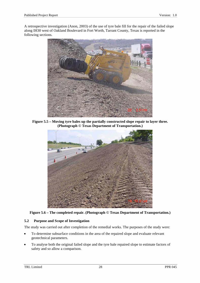
A retrospective investigation (Anon, 2003) of the use of tyre bale fill for the repair of the failed slope along IH30 west of Oakland Boulevard in Fort Worth, Tarrant County, Texas is reported in the following sections.
Figure 5.5 – Moving tyre bales up the partially constructed slope repair to layer three.
(Photograph © Texas Department of Transportation.)
Figure 5.6 – The completed repair. (Photograph © Texas Department of Transportation.)
5.2 Purpose and Scope of Investigation
The study was carried out after completion of the remedial works. The purposes of the study were:
• To determine subsurface conditions in the area of the repaired slope and evaluate relevant geotechnical parameters.
• To analyse both the original failed slope and the tyre bale repaired slope to estimate factors of safety and so allow a comparison.

29TRL Limited 29 PPR 045
Published Project Report Version: 1.0
• To highlight any other issues revealed so they can be incorporated into the design of similar repairs in the future.
The field investigation component of the study included the sinking of boreholes from which undisturbed and disturbed samples were recovered. Laboratory analyses of selected samples were undertaken to determine relevant engineering properties, and slope stability analyses were conducted to aid in the evaluation of the effects of the use of tyre bales as a partial replacement for fill soils in slope repair projects. The study was carried out by TEAM Consultants Inc for the Texas Department of Transportation (Anon, 2003).
Figure 5.7 – General view of the slope in May 2004.
Figure 5.8 – Water drained to the front face of the slope by layers one and two of the tyre bales, May 2004.

30TRL Limited 30 PPR 045
Published Project Report Version: 1.0
Figure 5.9 – Cracks at the crest of the slope in May 2004, demonstrating potential for further failure in the upper part of the slope which was backfilled with in-situ soil rather than tyre
bales.
5.3 Field Investigation
Boreholes were sunk at approximately the top of the slope, at either end of and just outside the repaired area. In each case the depth of the borehole was 30' (9.1m). The materials encountered were 2' (0.61m) of soft brown moist silty Clay overlying tan dry weathered fractured Limestone to a depth of 7' (2.1m) to 13' (4.0m), overlying stiff to hard brown moist shaly Clay to a depth of 23' (7.0m) and soft grey moist Shale/clayey Shale to the base of the boreholes. It seems likely that the shaly Clay is a weathered derivative of the grey Shale.
Undisturbed samples were taken using thin-walled Shelby tube samplers pushed in at 1' (0.3m) maximum intervals. Disturbed samples were obtained using a split barrel sampler in conjunction with Standard Penetration Test procedures (ASTM D1586; Anon, 1984a).
5.4 Laboratory Testing
Field soil classifications were verified by laboratory tests to determine the liquid limit, plastic limit (ASTM D4318; Anon, 1984b) and natural moisture content (ASTM D2216; Anon, 1980). Unit weight and strength parameters were also derived. The data are tabulated in Table 5.1.

31TRL Limited 31 PPR 045
Published Project Report Version: 1.0
Table 5.1 – Soil data derived from tests on the borehole samples and used in slope stability analyses.
Strata Depth, h: feet
(m)
Moisture Content,
w: %
Liquid Limit, LL: %
Plasticity Index, PI: %
Dry Density, ρ : pcf
(Mg/m3)
Direct Shear
Cohesion Intercept,
c': psf (kPa)
Direct Shear
Angle of Internal Friction,
φ' : o silty Clay 2 (0.6) 16.5-19.8 47-58 28-36 105
(1.682) 100 (5) 12
Weathered Limestone
10 (3.0)
- - - 115 (1.842)
100 (5) 20
shaly Clay 18 (5.5)
16.5-22.8 52-71 31-44 108 (1.730)
100 (5) 14
clayey Shale Base 21.2 56-63 31-36 118 (1.890)
250 (12) 20
Tyre Bales (Estimated)
N/A - - - 45 (0.721) 750 (36) 35
Tyre Bales (Measured: Zornberg, 2004)
N/A - - - 36.7±4 (0.588
±0.064)*
32 (1.5) 35.9
* The bulk (wet) density has been measured as 47.1 ± 5 pcf (or 0.755 ± 0.081 Mg/m3)
5.5 General Site and Subsurface Conditions
The original cut slope was estimated to have been constructed in the late 1950s or early 1960s based upon the approximate timing of the construction of IH30. The area is characterised by gently rolling terrain.
The site is located in an area underlain by deposits of the Grayson Marl and Main Street Limestone (undivided) and/or the Pawpaw Formation, Weno Limestone and Denton Clay (undivided); all of Cretaceous age, as shown on the Dallas sheet of the Geological Atlas of Texas (Anon, 1987). These formations vary but generally consist predominantly of calcareous clay and marl with thin limestone beds. Detailed photographic evidence of the strata in the unrepaired failed area (not presented here) indicated that the exposed materials had very similar characteristics to those generally used to describe the Weno Limestone; this was broadly confirmed by the recovered borehole samples. Typically the middle Weno Limestone formation is olive green to olive grey and includes alternating calcareous clay layers with sand sized shell debris.
The Washita Group, which includes the Grayson Marl and Main Street Limestone (undivided), has an approximate north-south strike with a due east dip of around 0.4o in the Tarrant County area (Anon, 1982) with no faults indicated in the vicinity of the site. (Anon, 1987). Field observations broadly confirmed these facts as recorded in the available literature.
One significant difference observed between the two boreholes was the presence of slickensided features in the borehole at the west end of the repaired area between the depths of 7' (2.1m) and 23' (7.0m). This is considered to be indicative of non-uniform desiccation, cracking and volume change in the past. It may also indicate that discrete blocks have formed within the soil mass leading to lower shear strengths compared to the intact condition. It is not necessarily indicative of large scale movements that would lead to a residual strength condition and such a condition has not been assumed here. The limestone stratum observed was weathered, fractured and dry. However, the materials encountered beneath the limestone in both boreholes were moist. Both boreholes were

32TRL Limited 32 PPR 045
Published Project Report Version: 1.0
reported to be dry at completion and no groundwater was encountered during drilling. These observations confirm the groundwater regime that might be expected from the observed strata with the limestone being highly permeable and the clay and shale materials being relatively impermeable.
5.6 Analyses
For the purpose of the back analysis of the failed slope and of the analysis of the repaired slope, slope geometry was taken as maximum height 20' (6.1m) with a constant slope of 1 in 3 (approximately 18o).
Unit weights and strength data for the strata were derived from the unconfined compressive stress and direct shear tests respectively. Soil strength parameters determined in the direct shear tests were taken as a starting point and modified in accordance with conditions observed and assumptions made.
The values used for unit weight and shear strength of the tyre bales were estimated from published data for equipment used to bale tyres and from data published by the US Environmental Protection Agency. Tyre bale data determined since this project was undertaken are also presented in Table 5.1. The measured values indicate that the cohesion is considerably less than that estimated and that the angle of internal friction is slightly higher than the estimate. In addition the estimated dry density falls approximately mid-way between the measured dry density and bulk density.
The soil samples tested were taken from stable areas at either end of the slope failure. It was strongly suspected that these had suffered less from the effects of weathering than the soils in the failed areas. This was due to the construction of a residential development immediately behind the area of the slope failure with no provision for positive surface water drainage (e.g., gullies). This is believed to have increased run-off into the area of slope that was to later fail, increasing the rate of weathering and also the moisture content and associated pore water pressures at times of heavy rainfall.
Initial analyses of slope stability were thus undertaken using the laboratory strength values. These indicated a significant factor of safety that may, as expected, have been close to the as-built conditions when the slopes were first constructed. The detrimental effects of weathering were taken into account in the analysis by modifying evaluated soil properties. The modified soil values were used for analysis purposes and then further modified for reanalysis until the calculated slope factor of safety reached a value of just slightly less than 1.0. The modified soil values so determined were then assumed to have been prevalent when slope failure occurred.
The soil values identified in this manner were then reused in further analyses after the placement of tyre bales in the original slope profile in order to evaluate the possibility that stability was improved. It is possible that the mechanisms at play just prior to or during failure may not be well represented by this technique. However, the assumptions made are considered to indicate soil properties that are at least representative of average conditions within the analysed portion of the slope. It is with this logic that stability analyses were employed in order to gain insight into the use of baled tyres as a substitute for high quality, high cost imported fill in slope repair projects.
The analyses were undertaken using a computer program developed by the University of Texas and modified to meet US Army Corps of Engineers requirements (UTEXAS2: Hughes, 1986).
All calculations were made using Spencer’s procedure (Spencer, 1967), in which all side forces are assumed to have the same inclination and all requirements for static equilibrium are satisfied. The solution requires that both force and moment equilibrium be satisfied. Circular analyses were undertaken for the back analysis of the failed slope and both circular and non-circular analyses were undertaken for the slope repaired using tyre bales.
5.6.1 Back Analysis of Cut Slope Failure
The assessment of the mode of failure, the geological model, was based upon a number of factors: discussions between TEAM Consultants Inc and Texas Department of Transportation personnel who visited the site soon after the failure occurred; photographs taken at that time and after the removal of

33TRL Limited 33 PPR 045
Published Project Report Version: 1.0
the failed material; and on the subsequent investigations. Based upon this evidence the geological model proposed was that of a classic rotational failure. The borehole records indicated moisture sensitive clays, which appeared to be slickensided at or below a depth of 7' (2.1m). When heavy rainfall occurred the overlying limestone is likely to have been saturated, increasing the loading in the underlying clay. This, when combined with associated increases in pore water pressure and the potential strength reducing effects of slickensiding, is likely to have led to shearing of the clays.
There was visible evidence of groundwater intrusion from the slope backwall after excavation of the failed area was completed. It appears that the failure was typical of those in the general vicinity. Heavy clay soils exposed in cuts or embankments lose shear strength with time through weathering and usually, although not always, fail during or following periods of extended and/or intense rainfall. Climatic factors are considered severe in this area and moisture sensitive clay soils may fail at slope angles as low as 10o (approximately 1 in 5.7). Slopes in heavy clay soils in this area have occasionally been constructed as steep as 1 in 2.5 (approximately 22o). The most prevalent constructed slope profile in this area ranges from 1 in 3 (approximately 18o) to 1 in 4 (approximately 14o).
Slope stability analyses based on the foregoing geological model were generally completed assuming that slope failure was slow enough to allow the stresses to be transferred to the soil structure as excess pore water pressures were rapidly dissipated after the onset of load.
Assuming a rotational shear failure and using soil parameters near the peaks observed during laboratory testing a factor of safety of 2.6 was calculated.
Weathering and saturation of the slope (with the groundwater table at the slope face) were then assumed to have had a negative impact on the slope and the associated soil parameters were assumed to decrease as a result of these factors for the purposes of analysis. The added overburden due to saturation and lowered strength values gave a calculated factor of safety of 1.2, again based on a rotational shear failure. Finally, the effects of saturation in terms of softening were accounted for by lowering the angle of internal friction thus transferring additional stresses to the pore fluid. The strength is thus presumed to have dropped and failure occurred. The factor of safety resulting from this analysis is unity, being broadly indicative of failure in the rotational shear failure mode assumed.
It is important to understand that the above analyses make a lot of assumptions and were for changes in soil strength and angle of internal friction with time under conditions neither measured nor observed. The assumptions do however represent a logical sequence as interpreted from the post-failure observations and investigations. The intention was that the analyses would provide a comparison of the conditions leading to failure or otherwise and not definitive factors of safety.
5.6.2 Analysis of Tyre Bale Repair
The use of tyre bales as a soil fill replacement was implemented at this site as an experiment in long term slope stability using such high permeability, lightweight materials. The potential for reuse of post-consumer tyres was a welcome added benefit. It was intended to indicate any potential for benefits to be derived from future repairs of this nature. Against this background the decision was made to execute the analysis for the originally proposed full-height tyre bale repair, as opposed to the part-height tyre bale repair implemented. Analysis of the slope as repaired in the field has not been performed.
The analysis of the slope incorporating tyre bales included some significant assumptions such as the mode of failure (circular or non-circular), shear strength of the composite stacked tyre bales, and the angle of shearing resistance either internal to the stacks of bales and/or the individual bales or external between the stacked bales and the adjacent supporting materials. It is worth noting at this point that the shear resistance of both the individual bales and of the composite stacks of bales is likely to be significantly in excess of that of both the boundary between the stacks and the adjacent soil and of the underlying soil itself. It thus seems highly likely that any failure is likely to be deflected to the boundary between bales and soil or deeper.

34TRL Limited 34 PPR 045
Published Project Report Version: 1.0
Notwithstanding that a series of laboratory results has become available since the analysis was undertaken and for shear between bales the assumptions are generally supported. The higher angle of internal friction and lower dry density measured compared to the original estimates for the analysis are broadly anticipated to go some way towards counteracting the effect of the lower cohesion (see Table 5.1).
A conservative approach was taken. Groundwater conditions were assumed to be reflected by the presence of the groundwater table at the interface between the in-situ soil and the tyre bales. This reflects the fact that the high porosity and permeability of the tyre bales are expected to allow the free passage of water to the face of the repair. This assumption was observed to be broadly correct during a site visit in May 2004 when water was observed (visually and audibly) to flow freely through the tyre bale mass to the face of the slope (see Figure 5.8). Soil parameters were then assumed which together gave a factor of safety indicative of failure.
In the analysis a portion of the slope profile was then replaced with stacked tyre bales and the groundwater surface placed at the boundary between the tyre bales and the in-situ soil. The supporting material strength was also reduced to one half the values used in the analysis of the cut slope. This was intended to simulate a worst case scenario of water ponding at the interface between the tyre bales and the underlying soil and causing substantial softening and strength reduction. In this case both circular and non-circular analyses were conducted. However, it was found that the circular analyses gave factors of safety much higher than those of the non-circular analyses. The more conservative results for the non-circular analysis gave an acceptable factor of safety against failure of 1.71, this having been calculated under close to worst case scenario conditions. Circular failure analysis results are not reported here.
5.7 Lessons Highlighted
This project has highlighted a number of lessons for the future design and construction of tyre bale slope repairs. Not least among these is the need to ensure that an adequate supply of tyres and thus tyre bales has been secured prior to the commencement of construction.
The need to isolate layers of tyre bales using in-situ soil as a precaution against spontaneous combustion has been the subject of much thought in the period since this project. The risks associated with not isolating individual layers of tyre bales is now regarded as minimal, for reasons explained earlier, and the potential for the creation of shear planes by such an approach recognised. Such an approach is unlikely to be repeated.
Even if tyre bales are butted up one against the other their sub-rectangular shape means that gaps will persist between bales, especially at the corners. It is recommended that future repairs of this nature should utilise coarse, dry sand to fill the gaps between adjacent tyre bales. Other coarse, dry materials may be utilised and crushed glass of a suitable grading has been highlighted as part of ongoing work as a suitable alternative. Vibration of the materials into the gaps between bales is recommended (Winter et al., 2005). Successive layers of bales should be placed directly on top of the layer immediately below. A stagger should be introduced thereby creating a degree of interlock between successive layers. The excavated, failed area should be completely filled in this manner. The sloping front face of the bales should be covered by topsoil or suitable in-situ material. Particular attention should be paid to drainage and ensuring that water cannot accumulate at the interfaces between the tyre bale fill and the supporting soil materials or transfer rapidly into adjacent lengths of untreated slope.
5.8 Conclusions
Observations of a slope failure repaired using tyre bales indicate that the portion so repaired remains stable and allows water to flow through to the front and base of the slope profile as originally envisaged. In contrast the upper portion of the slope was repaired conventionally, using fill materials

35TRL Limited 35 PPR 045
Published Project Report Version: 1.0
recovered from the failed area. Not surprisingly, as expansive soils in a largely uncompacted state were used, the upper part of the repair is showing signs of distress around two years after repair.
Retrospective studies were undertaken by TEAM Consultants Inc for the Texas Department of Transportation (Anon, 2003). These included slope stability analyses to provide a comparison of slope stability for the situation before and after the replacement of in-situ materials with tyre bales. The latter analysis assumed that the entire excavated volume was replaced with tyre bales, reflecting the intended, the desirable and the likely future approach to such repairs.
The results of the analysis indicate significant increases in the factors of safety derived, and thus a potentially considerable improvement in the long term repaired slope stability is possible where tyre bales are substituted for conventional soil backfill in areas where high plasticity clays predominate. There seems to be no reason to doubt that such an approach may be equally successful where lower plasticity clays predominate.
For future repairs of this nature it is recommended that coarse, dry sand is used to fill the gaps between adjacent tyre bales and that successive layers of bales are placed directly on top of the layer immediately below. The excavated, failed area should be completely filled in this manner. The sloping front face of the bales should be covered by topsoil or suitable in-situ material. Particular attention should be paid to drainage and ensuring that water cannot accumulate at the interfaces between the tyre bale fill and soil materials.
Tyre bales are porous with permeability comparable to typical gravel soils. This is indicative of their potential to improve conditions in the bulk of wet region slope failures in need of repair. Experience indicates that water and its deleterious effects are usually a primary cause of failure and thus the handling of water is a key issue to be addressed in any remedial action.
Layers of in-situ fill material between 8'' (0.203m) and 12'' (0.305m) thick were placed between the layers of tyre bales in an attempt to provide some protection against a perceived risk of fire caused by spontaneous combustion. This risk is now largely viewed as minimal and given the potential for such layers to act as incipient shear planes this approach is not likely to be repeated, nor is it recommended.
Tyre bales also require little or no protection from environmental elements (other than for aesthetic reasons) and yet should be very durable and stable for a significant time period. Costs for tyre bales should make their use economic, especially where their use is as a substitute for imported materials and in view of the added long term stability benefits, which should have a positive impact on the whole life cost of any slope in need of repair. Other benefits include the beneficial reuse of a waste material that is otherwise difficult to dispose of in an environmentally and legally sound manner and the potential for employment and associated wealth generation from the creation of tyre bales as a product.
5.9 Case Study Acknowledgements
The information presented in this case study was supplied Richard Williammee of the Fort Worth District of the Texas Department of Transportation and William Prikryl of TEAM Consultants Inc.

36TRL Limited 36 PPR 045
Published Project Report Version: 1.0
6 Flood Defence Embankment, Pevensey Bay, East Sussex, UK
6.1 Background
Pevensey Beach is a 9km shingle embankment that protects 50km2 of the low-lying Pevensey Levels, 35km2 of which is a Site of Special Scientific Interest (SSSI). Major beach replenishment took place during the summer of 2002. However, littoral drift through Pevensey bay results in a net loss to the frontage of 20,000m3 per year. This amount has to be added annually by way of maintenance recharge to preserve the improved defences. This would normally require the import of large amounts of natural shingle to build up the beach to the required level. If some of the shingle could be replaced by other materials this would preserve scarce resources of this valuable natural material. If materials that would otherwise be waste, such as used tyres, can be used to replace the shingle this gives additional environmental benefits. A trial was carried out at the Pevensey Bay Coast Road in which 350 tyre bales were buried in the landward side of the beach in November 2002, generating shingle that could be used elsewhere on the beach. The performance of the tyres bales has been monitored for over a year since construction. If successful, the trial could pave the way for much wider use of tyre bales for this purpose in beaches throughout the UK.
6.2 Comparative Performance
The trial was carried out as an awareness raising exercise of the potential uses of tyre bales in construction. It is partly funded by the Partners in Innovation programme run by the Department of Trade and Industry. The tyre bales are a replacement for bulk fill, and the main questions that the trial is addressing are:
• Are there any environmental issues with the use of tyres?
• Will the tyres wash away in big storms?
6.2.1 Environmental issues
Tyres are generally inert and durable materials. However there are concerns that they could release contaminants adhering to them as a result of use on roads, and metals from the reinforcing cords within the tyres. Evidence form an earlier study by the University of Southampton, of an artificial reef constructed from tyres in Poole Bay suggests that there may be an initial flow of material washed off the surface of the tyres, but that this is short-lived and reduces to low levels. To assess leaching, five groundwater sampling wells have been placed in and around the tyres bales on Pevensey Beach: one in the centre of the bales, one at each end, and two more distant ones in the surrounding beach. Zinc is used as the main indicator of tyre leaching.
The basal layer of tyre bales is founded just below the high water level of neap tides. It was thought that this would ensure that the basal layer was flooded daily. However, in practice it has been found that the hydraulic gradient across the beach is higher than anticipated, and it is only at spring tides that any water has been recorded in the wells. Monitoring will be continued for a year after construction and the results will be given in the final project report, due in 2005.
6.2.2 Resistance to storms
The tyres are buried in five layers, with the top level about 1.15m below the surface level of the beach. In addition, the area has been surcharged by 0.25m to allow for settlement. The area is crossed by traffic from the adjacent Environment Agency Salt Haven Depot on Coast Road, which has accelerated settlement and compaction of the overlying fill. Settlement plates have been installed in the tyre bales. These are being monitored over a period of one year from construction, and the results will be included in the final project report, due in 2005.

37TRL Limited 37 PPR 045
Published Project Report Version: 1.0
Tests carried out by HR Wallingford show that the tyres bales have high permeability in both the horizontal and vertical directions, similar to the clean, rounded gravel of the surrounding shingle. Measurements of water level will be made in the groundwater sampling wells to see if the bales cause any difference in water levels compared to surrounding areas of the beach.
It is anticipated that shingle will move into the voids in the tyre bales over time, and this will help to anchor the bales. Because the edges of the bales are rounded there are voids at the corners where the bales abut each other. During construction shingle was worked into these areas to help anchor the bales and avoid surface settlement. The return period for a storm big enough to uncover the edge of the bales will be calculated.
6.3 Material Detail and Specification
The tyre bales consist of 100 to 120 tyres compressed into a block 1.5m in length, 1.25m in width and 0.75m in depth. The bales have a density of about 0.7Mg/m3 or less, so are considerably lighter than the natural shingle. The bales are secured with five cords of stainless steel wire. It is anticipated that these will corrode over time; however experience has shown that the tyre bales retain their shape after the wires are removed. The ingress of shingle will also help to preserve the shape of the bales. Experiments are being carried out with nylon cord in place of stainless steel to see if this will last longer.
350 bales were used, placed in a block 14 bales long, 5 bales wide and 5 bales deep. A geogrid was placed on the shingle below the bales and wrapped round them as they were placed, so that the entire block is enclosed within the geogrid. The geogrid is a reinforcing geosynthetic fabric which holds the bales together, but has open spaces in a grid pattern that will allow shingle to migrate into the bales. The top surface of the bales is just over 1m below the level of the beach. Shingle from the excavation was used to backfill from the top of the bales to beach level.
If the trial is successful, this method of utilising used tyres could be used on a much larger scale at Pevensey and other beaches, and result in a significant demand for the number of used tyres produced in the UK each year. These tyres can no longer be disposed of to landfill, so alternative uses have to be found for them.
A method statement for the installation of the bales was prepared by the client, Pevensey Coastal Defence Limited. In addition, Planning Approval had to be obtained from the Environment Agency, and a waste management license was required for the use of the tyres.
6.4 Case Study Acknowledgements
The information presented in this case study was supplied by the client for the work (Ian Thomas of Pevensey Coastal Defence Limited) and the supplier of the tyre bales (Marcus Wells of Anglo Environmental Tyre Recycling).
This case study is based upon one originally prepared as part of a contract placed on TRL by WRAP. The authors are grateful to WRAP for permission to use the information contained therein. The original case study may be accessed at www.aggregain.org.uk.

38TRL Limited 38 PPR 045
Published Project Report Version: 1.0
7 Cut Slope Repair, Milton of Clava, Highland, UK At Milton of Clava a cut slope of maximum height around 3m separates a domestic driveway from a local road.
The slope had existed for many years without problems until water erosion became prevalent in 2002 (Figure 7.1). This coincided with the deposit of a large amount of material on the land upslope of the site as part of a railway repair, although a causal link has not been established.
Figure 7.1 – The effects of erosion on the slope. (Photograph © Northern Tyre Recycling.)
The flow of water and associated erosion was such that the land immediately below the slope became effectively unusable. Being a driveway permitting access to a garage and a large tract of land not otherwise easily accessible this presented something of a problem for the landowner.
A construction solution involving the use of tyre bales to capture and drain the water away from the slope was devised (Figures 7.2 and 7.3).
Figure 7.2 – Construction of the slope repair. (Photograph © Northern Tyre Recycling.)

39TRL Limited 39 PPR 045
Published Project Report Version: 1.0
Figure 7.3 – Schematic of the slope repair (Not To Scale).
The slope face was excavated and tyre bales were placed in the void created. This allowed the water coming from both above and behind the slope to be captured in the bales voids and drained to tyre bales forming a drain between the base of the slope and the driveway. The drain was carefully profiled so as to allow flow out to the mains drainage. The completed slope is shown in Figure 7.4.
Figure 7.4 – The completed slope immediately after construction. (Photograph © Northern Tyre Recycling.)
Tyre bales
Driveway
Local Road
Completed Earthworks
Profile
Excavated Earthworks
Profile
Tyre bales
Driveway
Local Road
Completed Earthworks
Profile
Excavated Earthworks
Profile

40TRL Limited 40 PPR 045
Published Project Report Version: 1.0
The slope has since shown no signs of further erosion or movement and as of June 2004 (some 2 years after construction) appears to be operating successfully (Figure 7.5).
Figure 7.5 – The completed slope in June 2004.
7.1 Case Study Acknowledgements
The information presented in this case study was supplied by Dennis Scott of Northern Tyre Recycling.

41TRL Limited 41 PPR 045
Published Project Report Version: 1.0
8 Balnain Flood Protection Works, Highland, UK The River Enrick just to the east of Balnain has flooded frequently in the past causing disruption to forestry operations and potential damage to salmon by the washing of fines back into the river.
In 2004 a flood control embankment was constructed. This had two purposes. First to reduce the instance of flooding of the River Enrick at this point and second to reduce the amount of fines washed into the river and to thus reduce the potential damage to salmon stocks. It was thus assumed that flood waters would pass through the embankment in extreme cases, but that the fines would be caught behind the embankment rather than being washed back into the river.
A 15m long embankment was constructed with a tyre bale core. In section the embankment base was four tyre bales wide. These were keyed into the existing river bank. Three further layers of tyre bales were placed symmetrically on the first layer: layer two was four bales wide in section, layer three was two bales wide in section and later four was one bale wide in section.
The embankment is shown in Figure 8.1 during construction and Figure 8.2 illustrates the completed works.
Figure 8.1 – The embankment during construction. (Photograph © Northern Tyre Recycling.)
8.1 Case Study Acknowledgements
The information presented in this case study was supplied by Dennis Scott of Northern Tyre Recycling.

42TRL Limited 42 PPR 045
Published Project Report Version: 1.0
Figure 8.2 – The embankment after construction.

43TRL Limited 43 PPR 045
Published Project Report Version: 1.0
9 Concrete Blocks, Milton of Clava, Highland, UK
9.1 Background
Northern Tyre Recycling (UK) Ltd recycles tyres into tyre blocks for various construction applications. In 2001 they had a requirement for a new ramp for their commercial vehicles and used the opportunity to test the use of tyre blocks in the construction of concrete blocks.
Concrete blocks were constructed in a mould. Reinforcing wire and tyre blocks were inserted into the mould in such a way that the reinforcing wire was enclosed by the wires that tie together the tyre block. Reinforcing wire was both above and below the tyre block within the concrete block (Figure 9.1). A vibrating poker was used when pouring the concrete to ensure the concrete filled all the voids within the tyre block.
Figure 9.1 – Manufacture of the concrete blocks. (Photograph © Northern Tyre Recycling.)
The result was a concrete "URRO" (Used Rubber Recycling Operation) block with a mass of less than half that of a conventional block (Figure 9.2 and 9.3). The concrete block with tyres weighing just over two tonnes, compared to an equivalent conventional block weighing approximately five tonnes.
Approximately 1,000 tyres were used in the construction of the blocks.
9.2 Savings
9.2.1 Direct savings
Savings are possible in this application because used tyres that need to be diverted from landfill are used to replace some of the primary materials that would normally be required in the concrete blocks.
£/block Quantity Total cost Cost of conventional concrete block 120-130 16 £1,920-£2,080 Cost of concrete block with tyres replaced 63 16 £1,008 Total Direct Savings 57-67 £912 - £1,072

44TRL Limited 44 PPR 045
Published Project Report Version: 1.0
Figure 9.2 – A completed concrete block shown alongside a tyre bale. (Photograph © Northern Tyre Recycling.)
Figure 9.3 – The completed vehicle ramp constructed from concrete tyre bale blocks.
9.2.2 Indirect savings
No additional costs were incurred as a result of constructing the blocks with used tyres. In addition to the direct savings outlined above there is an approximate £6 saving per block by avoiding the Aggregate Levy due to the reduced requirement for natural aggregates.
Indirect benefits
• Whole tyres have been banned from landfills since June 2003. While shredded tyres can still be sent to landfill, alternative sustainable means of recovering tyres rather than disposal are required.
• Fewer primary materials used to construct blocks.
• Blocks weigh less and therefore are easier to transport and manoeuvre during construction.

45TRL Limited 45 PPR 045
Published Project Report Version: 1.0
9.3 Lessons Learned and Technical Data
Tyres have not been used in the past in the construction of concrete blocks. This project has demonstrated that they can be used successfully in this application.
The ramp has been in use since June 2001. The ramp is used by a variety of vehicles from 1 tonne to 1.5 tonne cars to 14 tonne to 18 tonne trucks. The ramp is used between two and four times a week. Since construction the performance of the ramp has been observed and there are no signs of cracking or movement.
The water : cement : aggregate ratio used in the concrete blocks was 0.65 : 1.0 : 6.6. This ratio gives an estimated maximum concrete strength of C30. The blocks measure 1720mm (Length) by 920mm (Width) by 820mm (Height).
9.4 Case Study Acknowledgements
The information presented in this case study was supplied by Dennis Scott of Northern Tyre Recycling as client for the works and supplier of the tyre bales.
This case study is based upon one originally prepared as part of a contract placed on TRL by WRAP. The authors are grateful to WRAP for permission to use the information contained therein. The original case study may be accessed at www.aggregain.org.uk.

46TRL Limited 46 PPR 045
Published Project Report Version: 1.0
10 Retaining Wall, Pecos River/Lake Carlsblad, New Mexico, USA
10.1 Project Background
Lake Carlsblad is a popular, year-round recreational area in New Mexico and had been suffering serious erosion problems in the Pecos River area due to river currents and recreational use. Tyre bales have been successfully used in the construction of a retaining wall some 3' to 4' (0.91m to 1.22m) high and 4400' (1341m) long on the bank of the Pecos River bank near Lake Carlsblad. The project began in September 1997 and was completed in May 1998 and utilised approximately 700,000 waste tyres.
Several design options were reviewed by the City of Carlsblad before the concrete retaining wall schematically illustrated in Figure 10.1 was selected. It can be seen that tyre bales were used as a bulk material to save large amounts of concrete and other fill (Sonti et al., 2000).
Figure 10.1 – Schematic of the design for the Pecos River/Lake Carlsblad retaining wall (Not to scale).
10.2 Construction
Each bale was wrapped in wire mesh, not dissimilar to ‘chicken wire’, and placed on a 10'' (0.25m) thick reinforced concrete base while the concrete was still wet, using an excavator and chains. The tyre bales were then encapsulated in concrete which was faced with either stucco or rock to provide an acceptable fascia. An 8'' (0.2m) thick concrete wall was incorporated to provide a boundary between the footpath and water. The completed project is illustrated in Figure 10.2.
10.3 Case Study Acknowledgements
The information presented in this case study was supplied by Ed and Nancy Drew of Encore Systems Inc.
Reinforced Concrete
Rockfill
Tyre Bale
Drainage AggregateDrainage Aggregate
Footpath
Grass BankReinforced Concrete
Rockfill
Tyre Bale
Drainage AggregateDrainage Aggregate
Footpath
Grass Bank

47TRL Limited 47 PPR 045
Published Project Report Version: 1.0
Figure 10.2 – The completed works at Pecos River/Lake Carlsblad. (Photograph © Encore Systems Inc.)

48TRL Limited 48 PPR 045
Published Project Report Version: 1.0
Acknowledgements The work described in this report was carried out in the Infrastructure Division of TRL Limited. The authors are grateful to Dr J M Reid who carried out the quality review and auditing of this report.
The authors are extremely grateful to the efforts of the Project Advisory Group. Without their input this project would not have been possible. The authors are also grateful to WRAP for permission to use those case studies that are based upon ones originally prepared for AggRegain (www.aggregain.org.uk).
References Anon (1980). Standard method for laboratory determination of water (moisture) content of soil, rock, and soil-aggregate mixtures. Designation D 2216-80. 1986 Annual Book of ASTM Standards, Appendix 4, Construction, Volume 04.08 Soil and Rock; Building Stones. Philadelphia, PA: American Society for Testing and Materials.
Anon (1982). Occurrence, availability and chemical quality of ground water in the cretaceous aquifers of north-central Texas. Report 269, Volume 1. Texas Department of Water Resources, April.
Anon (1984a). Standard method for penetration test and split-barrel sampling of soils. Designation D 1586-84. 1986 Annual Book of ASTM Standards, Appendix 4, Construction, Volume 04.08 Soil and Rock; Building Stones. Philadelphia, PA: American Society for Testing and Materials.
Anon (1984b). Standard test method for liquid limit, plastic limit, and plasticity index of soils. Designation D 4318-84. 1986 Annual Book of ASTM Standards, Appendix 4, Construction, Volume 04.08 Soil and Rock; Building Stones. Philadelphia, PA: American Society for Testing and Materials.
Anon (1987). Geological Atlas of Texas, Dallas Sheet, 1:250,000. Bureau of Economic Geology. Austin, TX: University of Texas.
Anon (1998). Proposal to bale tires for use in road subgrade construction in two demonstration projects in Chautauqua County, New York. Falconer, NY: Chautauqua County Executive.
Anon (2001). Where the rubber really meets the road: Video. Falconer, NY: Chautauqua County Department of Public Facilities.
Anon (2003). Geotechnical investigation and analyses – slope failure repair utilizing baled tire fill, Interstate Highway 30 west of Oakland Blvd., Fort Worth, Tarrant County, Texas. Report by TEAM Consultant Inc to Fort Worth District, Texas Department of Transportation. Forth Worth, TX: Texas Department of Transportation.
Glover, T J (1997). Pocket Ref., Second Edition. Littleton, CO: Sequoia Publishing.
Hird, A B, P J Griffiths and R A Smith (2001). Tyre waste and resource management: a mass balance approach. Viridis Report VR2. Crowthorne: TRL Limited.
Hughes, S G (1986). UTEXAS2. Software GS 86-1. Geotechnical Engineering Centre, Civil Engineering Department. Austin, TX: University of Texas.
Hylands, K N and V Shulman (2003). Civil engineering applications of tyres. Viridis Report VR5. Crowthorne: TRL Limited.
Lambe, T W and Whitman, R V (1979). Soil mechanics, SI Version. New York: John Wiley & Sons.
Prikryl, W, R Williammee and M G Winter (2005). Slope Failure Repair using Tyre Bales at Interstate Highway 30, Tarrant County, Texas, USA. Quarterly Journal of Engineering Geology and Hydrogeology, 38(3).
Roadscanners (2003). The B871 tyre bale project – the use of recycled tyre bales in a lightweight road embankment over peat. Rovaniemi, Finland: Roadscanners.
SEPA (2002). Waste data digest 2002. Stirling: Scottish Environment Protection Agency.

49TRL Limited 49 PPR 045
Published Project Report Version: 1.0
Shulman, V L (2002). The status of post-consumer tyres in the European Union. Report VR3. Crowthorne: TRL Limited.
Simm, J D, M J Wallis and K Collins (2004). Sustainable re-use of tyres in port, coastal and river engineering: guidance for planning, implementation and maintenance. HRW Report EX 5070-2. Wallingford: HR Wallingford.
Sonti, K, S Senadheera, P W Jayawickrama, P T Nash and D D Gransberg (2000). Evaluate the uses for scrap tires in transportation facilities. Research Study No 0-1808, Centre for Multidisciplinary Research in Transportation. Lubbock, TX: Texas Tech University.
Spencer, E (1967). A Method of Analysis of the Stability of Embankments Assuming Parallel Inter-Slice Forces. Géotechnique, 17(1), 11-26.
Winter, M G (2002). A conceptual framework for the recycling of aggregates and other wastes. Proceedings of the Institution of Civil Engineers (Municipal Engineer), 151(3), 177-187.
Winter, M G (2005). Report on a Technical Visit to the United States of America: May 2004. The Delegate., Issue 45 (March). London: Royal Academy of Engineering.
Winter, M G, P E Johnson and J M Reid (2005). Construction of road foundations on soft ground using lightweight tyre bales. Proceedings, International Conference on Problematic Soils, GeoProb2005, Eastern Mediterranean University, Famagusta, N Cyprus, 25-27 May 2005.
Winter, M G, G R A Watts and P E Johnson (In Preparation). Tyre bales in Construction. Viridis Report. Crowthorne: TRL Limited.
Zornberg, J (2004). Validation of the effectiveness of tire bale use in slope repairs and embankment construction – report of laboratory results. Semi-Annual Progress Report, Project 5-9023-01. Fort Worth, TX: Texas Department of Transportation.


![f4 Chestionarul Bales[Exemplu]](https://img.pdfslide.net/doc/110x75/55cf9dd9550346d033af8495/f4-chestionarul-balesexemplu.jpg)


