Embed Size (px)
Citation preview
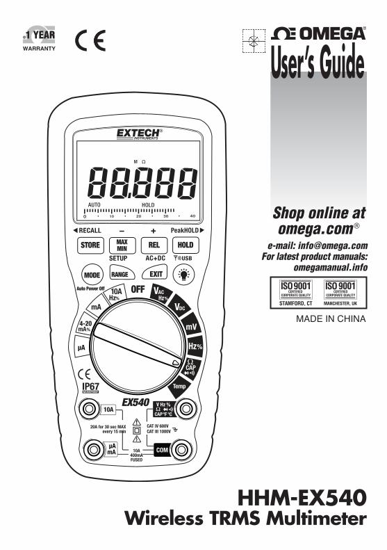
HHM-EX540Wireless TRMS Multimeter
e-mail: [email protected] latest product manuals:
omegamanual.info
Shop online atomega.com ®
User’s Guide
MADE IN CHINA

Servicing North America:U.S.A.: Omega Engineering, Inc., One Omega Drive, P.O. Box 4047ISO 9001 Certified Stamford, CT 06907-0047
Toll-Free: 1-800-826-6342 Tel: (203) 359-1660FAX: (203) 359-7700 e-mail: [email protected]
Canada: 976 BergarLaval (Quebec), H7L 5A1 Canada Toll-Free: 1-800-826-6342 TEL: (514) 856-6928FAX: (514) 856-6886 e-mail: [email protected]
For immediate technical or application assistance:U.S.A. and Canada: Sales Service: 1-800-826-6342/1-800-TC-OMEGA®
Customer Service: 1-800-622-2378/1-800-622-BEST®
Engineering Service: 1-800-872-9436/1-800-USA-WHEN®
Mexico En Español: 001 (203) 359-7803 FAX: 001 (203) 359-7807Latin America [email protected] e-mail: [email protected]
Servicing Europe:Benelux: Managed by the United Kingdom Office
Toll-Free: 0800 099 3344 TEL: +31 20 347 21 21FAX: +31 20 643 46 43 e-mail: [email protected]
Czech Republic: Frystatska 184733 01 Karviná, Czech RepublicToll-Free: 0800-1-66342 TEL: +420-59-6311899FAX: +420-59-6311114 e-mail: [email protected]
France: Managed by the United Kingdom OfficeToll-Free: 0800 466 342 TEL: +33 (0) 161 37 29 00FAX: +33 (0) 130 57 54 27 e-mail: [email protected]
Germany/ Austria: Daimlerstrasse 26D-75392 Deckenpfronn, GermanyToll-Free: 0800 6397678 TEL: +49 (0) 7056 9398-0FAX: +49 (0) 7056 9398-29 e-mail: [email protected]
United Kingdom: OMEGA Engineering Ltd.ISO 9001 Certified One Omega Drive, River Bend Technology Centre, Northbank
Irlam, Manchester M44 5BD United KingdomToll-Free: 0800-488-488 TEL: +44 (0) 161 777-6611FAX: +44 (0) 161 777-6622 e-mail: [email protected]
OMEGAnet® Online Service Internet e-mailomega.com [email protected]
It is the policy of OMEGA Engineering, Inc. to comply with all worldwide safety and EMC/EMIregulations that apply. OMEGA is constantly pursuing certification of its products to the European NewApproach Directives. OMEGA will add the CE mark to every appropriate device upon certification.The information contained in this document is believed to be correct, but OMEGA accepts no liability for anyerrors it contains, and reserves the right to alter specifications without notice.WARNING: These products are not designed for use in, and should not be used for, human applications.
2 EX540-EU-EN V1.4-3/11
Introduction This meter measures AC/DC Voltage, AC/DC Current, Resistance, Capacitance, Frequency (electrical & electronic), Duty Cycle, Diode Test, and Continuity plus Thermocouple Temperature. It can store and recall data. It features a waterproof, rugged design for heavy duty use. This meter can transmit data wirelessly when linked to a PC. Proper use and care of this meter will provide many years of reliable service.
Safety
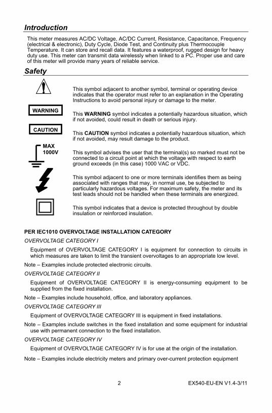
This symbol adjacent to another symbol, terminal or operating device indicates that the operator must refer to an explanation in the Operating Instructions to avoid personal injury or damage to the meter.
This WARNING symbol indicates a potentially hazardous situation, which if not avoided, could result in death or serious injury.
This CAUTION symbol indicates a potentially hazardous situation, which if not avoided, may result damage to the product.
This symbol advises the user that the terminal(s) so marked must not be connected to a circuit point at which the voltage with respect to earth ground exceeds (in this case) 1000 VAC or VDC.
This symbol adjacent to one or more terminals identifies them as being associated with ranges that may, in normal use, be subjected to particularly hazardous voltages. For maximum safety, the meter and its test leads should not be handled when these terminals are energized.
This symbol indicates that a device is protected throughout by double insulation or reinforced insulation.
PER IEC1010 OVERVOLTAGE INSTALLATION CATEGORY OVERVOLTAGE CATEGORY I
Equipment of OVERVOLTAGE CATEGORY I is equipment for connection to circuits in which measures are taken to limit the transient overvoltages to an appropriate low level.
Note – Examples include protected electronic circuits. OVERVOLTAGE CATEGORY II
Equipment of OVERVOLTAGE CATEGORY II is energy-consuming equipment to be supplied from the fixed installation.
Note – Examples include household, office, and laboratory appliances. OVERVOLTAGE CATEGORY III
Equipment of OVERVOLTAGE CATEGORY III is equipment in fixed installations. Note – Examples include switches in the fixed installation and some equipment for industrial
use with permanent connection to the fixed installation. OVERVOLTAGE CATEGORY IV
Equipment of OVERVOLTAGE CATEGORY IV is for use at the origin of the installation.
Note – Examples include electricity meters and primary over-current protection equipment
WARNING
CAUTION
MAX 1000V
3 EX540-EU-EN V1.4-3/11
SAFETY INSTRUCTIONS This meter has been designed for safe use, but must be operated with caution. The rules listed below must be carefully followed for safe operation.
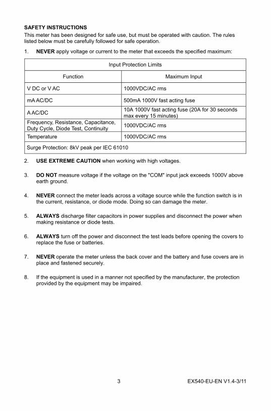
1. NEVER apply voltage or current to the meter that exceeds the specified maximum:
Input Protection Limits
Function Maximum Input
V DC or V AC 1000VDC/AC rms
mA AC/DC 500mA 1000V fast acting fuse
A AC/DC 10A 1000V fast acting fuse (20A for 30 seconds max every 15 minutes)
Frequency, Resistance, Capacitance, Duty Cycle, Diode Test, Continuity 1000VDC/AC rms
Temperature 1000VDC/AC rms
Surge Protection: 8kV peak per IEC 61010
2. USE EXTREME CAUTION when working with high voltages.
3. DO NOT measure voltage if the voltage on the "COM" input jack exceeds 1000V above earth ground.
4. NEVER connect the meter leads across a voltage source while the function switch is in the current, resistance, or diode mode. Doing so can damage the meter.
5. ALWAYS discharge filter capacitors in power supplies and disconnect the power when making resistance or diode tests.
6. ALWAYS turn off the power and disconnect the test leads before opening the covers to replace the fuse or batteries.
7. NEVER operate the meter unless the back cover and the battery and fuse covers are in place and fastened securely.
8. If the equipment is used in a manner not specified by the manufacturer, the protection provided by the equipment may be impaired.
4 EX540-EU-EN V1.4-3/11
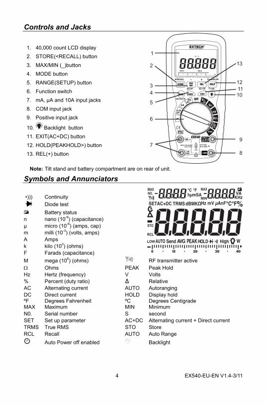
Controls and Jacks
1. 40,000 count LCD display 2. STORE(<RECALL) button 3. MAX/MIN (_)button 4. MODE button 5. RANGE(SETUP) button 6. Function switch 7. mA, µA and 10A input jacks 8. COM input jack 9. Positive input jack
10. Backlight button 11. EXIT(AC+DC) button 12. HOLD(PEAKHOLD>) button 13. REL(+) button
Note: Tilt stand and battery compartment are on rear of unit.
Symbols and Annunciators •))) Continuity
Diode test Battery status
n nano (10-9) (capacitance) µ micro (10-6) (amps, cap) m milli (10-3) (volts, amps) A Amps k kilo (103) (ohms) F Farads (capacitance) M mega (106) (ohms) RF transmitter active Ω Ohms PEAK Peak Hold Hz Hertz (frequency) V Volts % Percent (duty ratio) Relative AC Alternating current AUTO Autoranging DC Direct current HOLD Display hold ºF Degrees Fahrenheit ºC Degrees Centigrade MAX Maximum MIN Minimum N0. Serial number S second SET Set up parameter AC+DC Alternating current + Direct current TRMS True RMS STO Store RCL Recall AUTO Auto Range
Auto Power off enabled Backlight
1
2
3
4
5
6
7
13
12
11
10
9
8
5 EX540-EU-EN V1.4-3/11
Operating Instructions
WARNING: Risk of electrocution. High-voltage circuits, both AC and DC, are very dangerous and should be measured with great care.
1. ALWAYS turn the function switch to the OFF position when the meter is not in use.
2. If “OL” appears in the display during a measurement, the value exceeds the range you have selected. Change to a higher range.
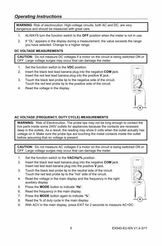
DC VOLTAGE MEASUREMENTS
CAUTION: Do not measure DC voltages if a motor on the circuit is being switched ON or OFF. Large voltage surges may occur that can damage the meter.
1. Set the function switch to the VDC position. 2. Insert the black test lead banana plug into the negative COM jack.
Insert the red test lead banana plug into the positive V jack. 3. Touch the black test probe tip to the negative side of the circuit.
Touch the red test probe tip to the positive side of the circuit. 4. Read the voltage in the display.
AC VOLTAGE (FREQUENCY, DUTY CYCLE) MEASUREMENTS WARNING: Risk of Electrocution. The probe tips may not be long enough to contact the live parts inside some 240V outlets for appliances because the contacts are recessed deep in the outlets. As a result, the reading may show 0 volts when the outlet actually has voltage on it. Make sure the probe tips are touching the metal contacts inside the outlet before assuming that no voltage is present. CAUTION: Do not measure AC voltages if a motor on the circuit is being switched ON or OFF. Large voltage surges may occur that can damage the meter.
1. Set the function switch to the VAC/Hz/% position. 2. Insert the black test lead banana plug into the negative COM jack.
Insert red test lead banana plug into the positive V jack. 3. Touch the black test probe tip to the neutral side of the circuit.
Touch the red test probe tip to the “hot” side of the circuit. 4. Read the voltage in the main display and the frequency in the right
auxiliary display 5. Press the MODE button to indicate “Hz”. 6. Read the frequency in the main display. 7. Press the MODE button again to indicate “%”. 8. Read the % of duty cycle in the main display. 9. With ACV in the main display, press EXIT for 2 seconds to measure AC+DC.
6 EX540-EU-EN V1.4-3/11
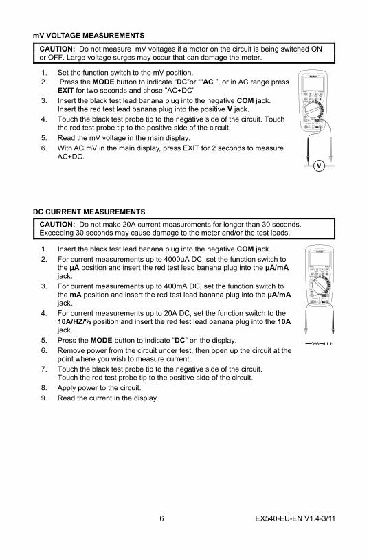
mV VOLTAGE MEASUREMENTS
CAUTION: Do not measure mV voltages if a motor on the circuit is being switched ON or OFF. Large voltage surges may occur that can damage the meter.
1. Set the function switch to the mV position. 2. Press the MODE button to indicate “DC”or ““AC ”, or in AC range press
EXIT for two seconds and chose ”AC+DC” 3. Insert the black test lead banana plug into the negative COM jack.
Insert the red test lead banana plug into the positive V jack. 4. Touch the black test probe tip to the negative side of the circuit. Touch
the red test probe tip to the positive side of the circuit. 5. Read the mV voltage in the main display. 6. With AC mV in the main display, press EXIT for 2 seconds to measure
AC+DC.
DC CURRENT MEASUREMENTS CAUTION: Do not make 20A current measurements for longer than 30 seconds. Exceeding 30 seconds may cause damage to the meter and/or the test leads.
1. Insert the black test lead banana plug into the negative COM jack. 2. For current measurements up to 4000µA DC, set the function switch to
the µA position and insert the red test lead banana plug into the µA/mA jack.
3. For current measurements up to 400mA DC, set the function switch to the mA position and insert the red test lead banana plug into the µA/mA jack.
4. For current measurements up to 20A DC, set the function switch to the 10A/HZ/% position and insert the red test lead banana plug into the 10A jack.
5. Press the MODE button to indicate “DC” on the display. 6. Remove power from the circuit under test, then open up the circuit at the
point where you wish to measure current. 7. Touch the black test probe tip to the negative side of the circuit.
Touch the red test probe tip to the positive side of the circuit. 8. Apply power to the circuit. 9. Read the current in the display.
7 EX540-EU-EN V1.4-3/11
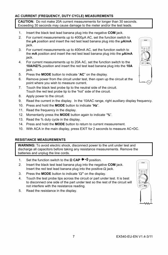
AC CURRENT (FREQUENCY, DUTY CYCLE) MEASUREMENTS CAUTION: Do not make 20A current measurements for longer than 30 seconds. Exceeding 30 seconds may cause damage to the meter and/or the test leads.
1. Insert the black test lead banana plug into the negative COM jack. 2. For current measurements up to 4000µA AC, set the function switch to
the µA position and insert the red test lead banana plug into the µA/mA jack.
3. For current measurements up to 400mA AC, set the function switch to the mA position and insert the red test lead banana plug into the µA/mA jack.
4. For current measurements up to 20A AC, set the function switch to the 10A/HZ/% position and insert the red test lead banana plug into the 10A jack.
5. Press the MODE button to indicate “AC” on the display. 6. Remove power from the circuit under test, then open up the circuit at the
point where you wish to measure current. 7. Touch the black test probe tip to the neutral side of the circuit.
Touch the red test probe tip to the “hot” side of the circuit. 8. Apply power to the circuit. 9. Read the current in the display. In the 10AAC range, right auxiliary display frequency. 10. Press and hold the MODE button to indicate “Hz”. 11. Read the frequency in the display. 12. Momentarily press the MODE button again to indicate “%”. 13. Read the % duty cycle in the display. 14. Press and hold the MODE button to return to current measurement. 10. With ACA in the main display, press EXIT for 2 seconds to measure AC+DC.
RESISTANCE MEASUREMENTS WARNING: To avoid electric shock, disconnect power to the unit under test and discharge all capacitors before taking any resistance measurements. Remove the batteries and unplug the line cords.
1. Set the function switch to the Ω CAP position. 2. Insert the black test lead banana plug into the negative COM jack.
Insert the red test lead banana plug into the positive Ω jack. 3. Press the MODE button to indicate “Ω” on the display. 4. Touch the test probe tips across the circuit or part under test. It is best
to disconnect one side of the part under test so the rest of the circuit will not interfere with the resistance reading.
5. Read the resistance in the display.
8 EX540-EU-EN V1.4-3/11
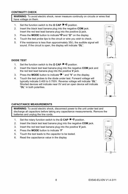
CONTINUITY CHECK WARNING: To avoid electric shock, never measure continuity on circuits or wires that have voltage on them.
1. Set the function switch to the Ω CAP position. 2. Insert the black lead banana plug into the negative COM jack.
Insert the red test lead banana plug into the positive Ω jack. 3. Press the MODE button to indicate“ "and “Ω” on the display 4. Touch the test probe tips to the circuit or wire you wish to check. 5. If the resistance is less than approximately 35Ω, the audible signal will
sound. If the circuit is open, the display will indicate “OL”.
DIODE TEST 1. Set the function switch to the Ω CAP position. 2. Insert the black test lead banana plug into the negative COM jack and
the red test lead banana plug into the positive V jack. 3. Press the MODE button to indicate“ “ and “V” on the display. 4. Touch the test probes to the diode under test. Forward voltage will
typically indicate 0.400 to 0.700V. Reverse voltage will indicate “OL”. Shorted devices will indicate near 0V and an open device will indicate “OL” in both polarities.
CAPACITANCE MEASUREMENTS
WARNING: To avoid electric shock, disconnect power to the unit under test and discharge all capacitors before taking any capacitance measurements. Remove the batteries and unplug the line cords.
1. Set the rotary function switch to the Ω CAP position. 2. Insert the black test lead banana plug into the negative COM jack. 3. Insert the red test lead banana plug into the positive V jack. 4. Press the MODE button to indicate “F” 5. Touch the test leads to the capacitor to be tested. 6. Read the capacitance value in the display
9 EX540-EU-EN V1.4-3/11
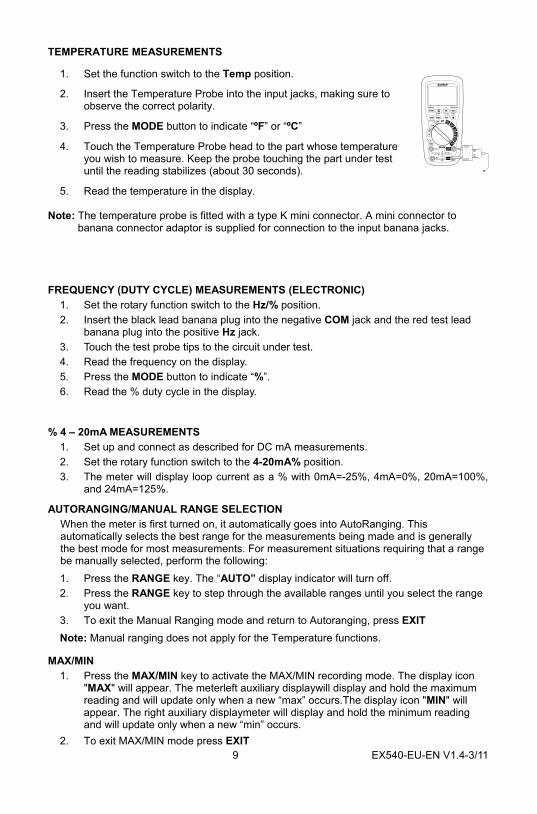
TEMPERATURE MEASUREMENTS
1. Set the function switch to the Temp position.
2. Insert the Temperature Probe into the input jacks, making sure to observe the correct polarity.
3. Press the MODE button to indicate “ºF” or “ºC”
4. Touch the Temperature Probe head to the part whose temperature you wish to measure. Keep the probe touching the part under test until the reading stabilizes (about 30 seconds).
5. Read the temperature in the display. Note: The temperature probe is fitted with a type K mini connector. A mini connector to
banana connector adaptor is supplied for connection to the input banana jacks. FREQUENCY (DUTY CYCLE) MEASUREMENTS (ELECTRONIC)
1. Set the rotary function switch to the Hz/% position. 2. Insert the black lead banana plug into the negative COM jack and the red test lead
banana plug into the positive Hz jack. 3. Touch the test probe tips to the circuit under test. 4. Read the frequency on the display. 5. Press the MODE button to indicate “%”. 6. Read the % duty cycle in the display.
% 4 – 20mA MEASUREMENTS
1. Set up and connect as described for DC mA measurements. 2. Set the rotary function switch to the 4-20mA% position. 3. The meter will display loop current as a % with 0mA=-25%, 4mA=0%, 20mA=100%,
and 24mA=125%.
AUTORANGING/MANUAL RANGE SELECTION When the meter is first turned on, it automatically goes into AutoRanging. This automatically selects the best range for the measurements being made and is generally the best mode for most measurements. For measurement situations requiring that a range be manually selected, perform the following: 1. Press the RANGE key. The “AUTO” display indicator will turn off. 2. Press the RANGE key to step through the available ranges until you select the range
you want. 3. To exit the Manual Ranging mode and return to Autoranging, press EXIT Note: Manual ranging does not apply for the Temperature functions.
MAX/MIN 1. Press the MAX/MIN key to activate the MAX/MIN recording mode. The display icon
"MAX" will appear. The meterleft auxiliary displaywill display and hold the maximum reading and will update only when a new “max” occurs.The display icon "MIN" will appear. The right auxiliary displaymeter will display and hold the minimum reading and will update only when a new “min” occurs.
2. To exit MAX/MIN mode press EXIT
10 EX540-EU-EN V1.4-3/11
RELATIVE MODE The relative measurement feature allows you to make measurements relative to a stored reference value. A reference voltage, current, etc. can be stored and measurements made in comparison to that value. The displayed value is the difference between the reference value and the measured value.
1. Perform the measurement as described in the operating instructions. 2. Press the REL button to store the reading in the display and the "" indicator will
appear on the display. 3. The Right auxiliary display displays the initial reading (the stored value) 4. The Left auxiliary display displays the actual currently measured value. 5. Main display displays the Relative value (currently measured value minus the stored
value).
DISPLAY BACKLIGHT
Press the key to turn the backlight on. The backlight will automatically turn off after SET time. Press the EXIT button to exit the backlight on mode.
HOLD The hold function freezes the reading in the display. Press the HOLD key momentarily to activate or to exit the HOLD function.
PEAK HOLD The Peak Hold function captures the peak AC or DC voltage or current. The meter can capture negative or positive peaks as fast as 1 millisecond in duration. Momentarily press the PEAK button, “PEAK” and “MAX” will display in left auxiliary display. MIN” will display in right auxiliary display. The meter will update the dispay each time a lower negative peak occurs. Press the EXIT button to exit the PEAK HOLD mode. Auto Power Off feature will be disabled automatically in this mode.
DATA STORAGE 1. Set the function switch to the measurement function desired. 2. Press the STORE button to enter the STORE function. The left upper aux display
indicates the current storage location (0000 to 9999). New measurements will begin storing into the next location.
3. Press the PEAKHOLD button to change into the initial storage number 0000. (Press it again to change back). On the right upper aux display shows XXXX which states how many current storage locations are used.
4. Press STORE button again to enter into recording interval time set up function. 5. The left upper aux display indicates 0000 S, which is the recording sample rate; use
the + & - buttons to select the sample rate desired (0 to 255 sec) 6. Set the sample rate to 0000 S for manual recording. In this mode, each press of the
STORE button will save one measurement reading. 7. Set the sample rate to 1 to 255 S for automatic recording. In this mode, pressing the
STORE button will start data recording at the set sample rate. 8. Press the EXIT button to end the recording session.
11 EX540-EU-EN V1.4-3/11
DATA STORAGE RECALL 1. Press STORE button for two seconds to enter into RECALL function. 2. On the left upper aux display will show XXXX, which is the current storage location.
The right aux display will show XXXX, which is the number of storage locations currently used.
3. Press the + or — button to select the storage location. The value in that location will be indicated in the main display.
4. Press the PEAKHOLD button once to continuously scan data from 0000 to XXXX. Press again then scan again.
5. Press the EXIT button to end the recall session.
CLEARING MEMORY To clear the memory of all stored data, from the OFF position, hold the EXIT button and switch the function switch to any position. Release the EXIT button and the LCD will flash 3 times and a buzzer will beep three times. Memory is now clear.
PC WIRELESS COMMUNICATION: 1. Install and launch the pc software 2. Press and Hold the backlight button for two seconds to enter RF wireless transmit
mode. 3. The RF icon will appear on the display. 4. When communication is established, the RF icon on the display will blink and the led
indicator on the receiver will also blink. 5. Once per second, the data will be displayed on the pc screen, plotted and inserted
into a list. 6. Hold the backlight button for two seconds to exit the RF wireless transmit mode
SENDING STORED DATA TO THE PC 1. Launch the pc software 2. Press the STORE button for two seconds to enter into data RECALL function. 3. Press the HOLD button for two seconds. The RF transmit icon will flash while the
stored data is sent to the pc
SETUP 1. Press and Hold the RANGE/SETUP button for two seconds to enter the SET function.
The first of five settable functions will appear. 2. Press the RANGE button to step through the functions
A: Upper limit buzzer alarm OFF or Value B: Lower limit buzzer alarm OFF or Value C: Auto power off time OFF, 10 to 30 sec D: Button beeper ON/OFF
E: Back light time OFF, 10 to 30 sec Use the +, - , and buttons to select and change conditions and digits.
3. Press the RANGE/SETUP button until the meter returns to the normal display to exit this mode.
AC+DC In the measuring modes VAC, mV(AC), 10A(AC), mA(AC) and uA(AC), press the EXIT button for 2 seconds to enter into AC+DC testing. The precision is the same as in the AC measure modes. The LCD shows AC+DC icon. Press the EXIT button to exit the mode.
LOW BATTERY INDICATION
When the icon appears in the display, the battery should be replaced
12 EX540-EU-EN V1.4-3/11
Maintenance WARNING: To avoid electric shock, disconnect the test leads from any source of voltage before removing the back cover or the battery or fuse covers.
WARNING: To avoid electric shock, do not operate your meter until the battery and fuse covers are in place and fastened securely.
This MultiMeter is designed to provide years of dependable service, if the following care instructions are performed:
1. KEEP THE METER DRY. If it gets wet, wipe it off.
2. USE AND STORE THE METER IN NORMAL TEMPERATURES. Temperature extremes can shorten the life of the electronic parts and distort or melt plastic parts.
3. HANDLE THE METER GENTLY AND CAREFULLY. Dropping it can damage the electronic parts or the case.
4. KEEP THE METER CLEAN. Wipe the case occasionally with a damp cloth. DO NOT use chemicals, cleaning solvents, or detergents.
5. USE ONLY FRESH BATTERIES OF THE RECOMMENDED SIZE AND TYPE. Remove old or weak batteries so they do not leak and damage the unit.
6. IF THE METER IS TO BE STORED FOR A LONG PERIOD OF TIME, the batteries should be removed to prevent damage to the unit.
13 EX540-EU-EN V1.4-3/11
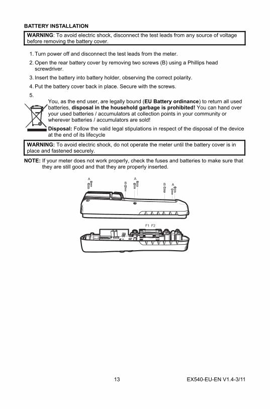
BATTERY INSTALLATION WARNING: To avoid electric shock, disconnect the test leads from any source of voltage before removing the battery cover.
1. Turn power off and disconnect the test leads from the meter. 2. Open the rear battery cover by removing two screws (B) using a Phillips head
screwdriver. 3. Insert the battery into battery holder, observing the correct polarity. 4. Put the battery cover back in place. Secure with the screws. 5.
You, as the end user, are legally bound (EU Battery ordinance) to return all used batteries, disposal in the household garbage is prohibited! You can hand over your used batteries / accumulators at collection points in your community or wherever batteries / accumulators are sold! Disposal: Follow the valid legal stipulations in respect of the disposal of the device at the end of its lifecycle
WARNING: To avoid electric shock, do not operate the meter until the battery cover is in place and fastened securely.
NOTE: If your meter does not work properly, check the fuses and batteries to make sure that they are still good and that they are properly inserted.
A A
ABB
F1 F2
14 EX540-EU-EN V1.4-3/11
REPLACING THE FUSES
WARNING: To avoid electric shock, disconnect the test leads from any source of voltage before removing the meter cover.
1. Disconnect the test leads from the meter. 2. Remove the protective rubber holster. 3. Remove the battery cover (two “B” screws) and the battery. 4. Remove the six “A” screws securing the rear cover. 5. Gently remove the old fuse and install the new fuse into the holder. 6. Always use a fuse of the proper size and value (0.5A/1000V fast blow for the 400mA
range [SIBA 70-172-40], 10A/1000V fast blow for the 20A range [SIBA 50-199-06]). 7. Replace and secure the rear cover, battery and battery cover.
WARNING: To avoid electric shock, do not operate your meter until the fuse cover is in place and fastened securely.
FCC Part 15 This equipment has been tested and found to comply with the limits for a Class B digital device, pursuant to part 15 of the FCC Rules. These limits are designed to provide reasonable protection against harmful interference in a residential installation. This equipment generates, uses and can radiate radio frequency energy and, if not installed and used in accordance with the instructions, may cause harmful interference to radio communications. However, there is no guarantee that interference will not occur in a particular installation. If this equipment does cause harmful interference to radio or television reception, which can be determined by turning the equipment off and on, the user is encouraged to try to correct the interference by one or more of the following measures: —Reorient or relocate the receiving antenna. —Increase the separation between the equipment and receiver. —Connect the equipment into an outlet on a circuit different from that to which the receiver
is connected. —Consult the dealer or an experienced radio/TV technician for help. Warning: Changes or modifications not expressly approved by the party responsible for compliance could void the user's authority to operate the equipment.
15 EX540-EU-EN V1.4-3/11
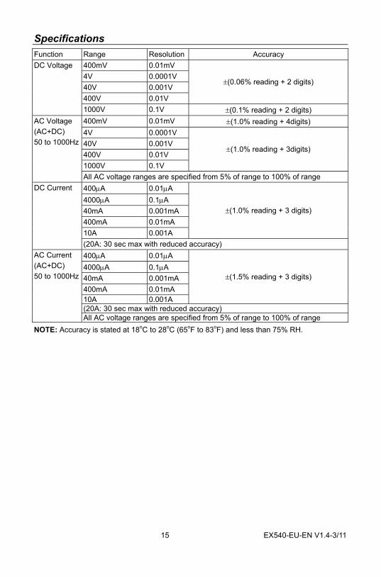
Specifications Function Range Resolution Accuracy
400mV 0.01mV 4V 0.0001V 40V 0.001V 400V 0.01V
±(0.06% reading + 2 digits)
DC Voltage
1000V 0.1V ±(0.1% reading + 2 digits) 400mV 0.01mV ±(1.0% reading + 4digits) 4V 0.0001V 40V 0.001V 400V 0.01V 1000V 0.1V
±(1.0% reading + 3digits)
AC Voltage (AC+DC) 50 to 1000Hz
All AC voltage ranges are specified from 5% of range to 100% of range 400μA 0.01μA 4000μA 0.1μA 40mA 0.001mA 400mA 0.01mA 10A 0.001A
±(1.0% reading + 3 digits)
DC Current
(20A: 30 sec max with reduced accuracy) 400μA 0.01μA 4000μA 0.1μA 40mA 0.001mA 400mA 0.01mA 10A 0.001A
±(1.5% reading + 3 digits)
(20A: 30 sec max with reduced accuracy)
AC Current (AC+DC) 50 to 1000Hz
All AC voltage ranges are specified from 5% of range to 100% of range NOTE: Accuracy is stated at 18oC to 28oC (65oF to 83oF) and less than 75% RH.
16 EX540-EU-EN V1.4-3/11
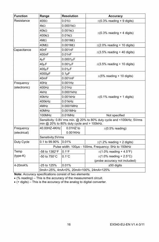
Function Range Resolution Accuracy 400Ω 0.01Ω ±(0.3% reading + 9 digits) 4kΩ 0.0001kΩ 40kΩ 0.001kΩ 400kΩ 0.01kΩ 4MΩ 0.001MΩ
±(0.3% reading + 4 digits)
Resistance
40MΩ 0.001MΩ ±(2.0% reading + 10 digits) 40nF 0.001nF 400nF 0.01nF
±(3.5% reading + 40 digits)
4μF 0.0001μF 40μF 0.001μF 400μF 0.01μF
±(3.5% reading + 10 digits)
4000µF 0.1µF
Capacitance
40mF 0.001mF ±(5% reading + 10 digits)
40Hz 0.001Hz 400Hz 0.01Hz 4kHz 0.0001kHz 40kHz 0.001kHz 400kHz 0.01kHz 4MHz 0.0001MHz 40MHz 0.001MHz
±(0.1% reading + 1 digits)
100MHz 0.01MHz Not specified
Frequency (electronic)
Sensitivity: 0.8V rms min. @ 20% to 80% duty cycle and <100kHz; 5Vrms min @ 20% to 80% duty cycle and > 100kHz. 40.00HZ-4KHz 0.01HZ to
0.001KHz ±(0.5% reading) Frequency
(electrical) Sensitivity:5Vrms 0.1 to 99.90% 0.01% ±(1.2% reading + 2 digits) Duty Cycle
Pulse width: 100µs - 100ms, Frequency: 5Hz to 150kHz -58 to 1382°F 0.1°F Temp
(type-K) -50 to 750°C 0.1°C ±(1.0% reading + 4.5°F) ±(1.0% reading + 2.5°C)
(probe accuracy not included) -25 to 125% 0.01% ±50 digits 4-20mA% 0mA=-25%, 4mA=0%, 20mA=100%, 24mA=125%
Note: Accuracy specifications consist of two elements: • (% reading) – This is the accuracy of the measurement circuit. • (+ digits) – This is the accuracy of the analog to digital converter.
17 EX540-EU-EN V1.4-3/11
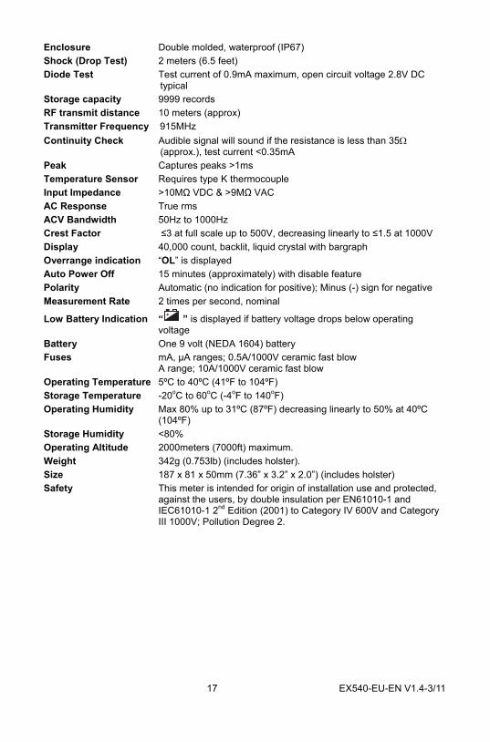
Enclosure Double molded, waterproof (IP67) Shock (Drop Test) 2 meters (6.5 feet) Diode Test Test current of 0.9mA maximum, open circuit voltage 2.8V DC
typical Storage capacity 9999 records RF transmit distance 10 meters (approx) Transmitter Frequency 915MHz Continuity Check Audible signal will sound if the resistance is less than 35Ω
(approx.), test current <0.35mA Peak Captures peaks >1ms Temperature Sensor Requires type K thermocouple Input Impedance >10MΩ VDC & >9MΩ VAC AC Response True rms ACV Bandwidth 50Hz to 1000Hz Crest Factor ≤3 at full scale up to 500V, decreasing linearly to ≤1.5 at 1000V Display 40,000 count, backlit, liquid crystal with bargraph Overrange indication “OL” is displayed Auto Power Off 15 minutes (approximately) with disable feature Polarity Automatic (no indication for positive); Minus (-) sign for negative Measurement Rate 2 times per second, nominal
Low Battery Indication “ ” is displayed if battery voltage drops below operating voltage
Battery One 9 volt (NEDA 1604) battery Fuses mA, µA ranges; 0.5A/1000V ceramic fast blow
A range; 10A/1000V ceramic fast blow Operating Temperature 5ºC to 40ºC (41ºF to 104ºF) Storage Temperature -20oC to 60oC (-4oF to 140oF) Operating Humidity Max 80% up to 31ºC (87ºF) decreasing linearly to 50% at 40ºC
(104ºF) Storage Humidity <80% Operating Altitude 2000meters (7000ft) maximum. Weight 342g (0.753lb) (includes holster). Size 187 x 81 x 50mm (7.36” x 3.2” x 2.0”) (includes holster) Safety This meter is intended for origin of installation use and protected,
against the users, by double insulation per EN61010-1 and IEC61010-1 2nd Edition (2001) to Category IV 600V and Category III 1000V; Pollution Degree 2.
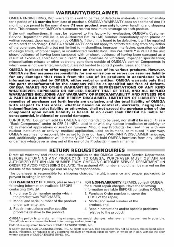
WARRANTY/DISCLAIMEROMEGA ENGINEERING, INC. warrants this unit to be free of defects in materials and workmanshipfor a period of 13 months from date of purchase. OMEGA’s WARRANTY adds an additional one (1)month grace period to the normal one (1) year product warranty to cover handling and shippingtime. This ensures that OMEGA’s customers receive maximum coverage on each product. If the unit malfunctions, it must be returned to the factory for evaluation. OMEGA’s CustomerService Department will issue an Authorized Return (AR) number immediately upon phone orwritten request. Upon examination by OMEGA, if the unit is found to be defective, it will be repairedor replaced at no charge. OMEGA’s WARRANTY does not apply to defects resulting from any actionof the purchaser, including but not limited to mishandling, improper interfacing, operation outsideof design limits, improper repair, or unauthorized modification. This WARRANTY is VOID if the unitshows evidence of having been tampered with or shows evidence of having been damaged as aresult of excessive corrosion; or current, heat, moisture or vibration; improper specification;misapplication; misuse or other operating conditions outside of OMEGA’s control. Components inwhich wear is not warranted, include but are not limited to contact points, fuses, and triacs.OMEGA is pleased to offer suggestions on the use of its various products. However, OMEGA neither assumes responsibility for any omissions or errors nor assumes liabilityfor any damages that result from the use of its products in accordance withinformation provided by OMEGA, either verbal or written. OMEGA warrants only thatthe parts manufactured by the company will be as specified and free of defects.OMEGA MAKES NO OTHER WARRANTIES OR REPRESENTATIONS OF ANY KINDWHATSOEVER, EXPRESSED OR IMPLIED, EXCEPT THAT OF TITLE, AND ALL IMPLIEDWARRANTIES INCLUDING ANY WARRANTY OF MERCHANTABILITY AND FITNESS FORA PARTICULAR PURPOSE ARE HEREBY DISCLAIMED. LIMITATION OF LIABILITY: Theremedies of purchaser set forth herein are exclusive, and the total liability of OMEGAwith respect to this order, whether based on contract, warranty, negligence,indemnification, strict liability or otherwise, shall not exceed the purchase price of thecomponent upon which liability is based. In no event shall OMEGA be liable forconsequential, incidental or special damages.CONDITIONS: Equipment sold by OMEGA is not intended to be used, nor shall it be used: (1) as a“Basic Component” under 10 CFR 21 (NRC), used in or with any nuclear installation or activity; or(2) in medical applications or used on humans. Should any Product(s) be used in or with anynuclear installation or activity, medical application, used on humans, or misused in any way,OMEGA assumes no responsibility as set forth in our basic WARRANTY/ DISCLAIMER language,and, additionally, purchaser will indemnify OMEGA and hold OMEGA harmless from any liabilityor damage whatsoever arising out of the use of the Product(s) in such a manner.
RETURN REQUESTS/INQUIRIESDirect all warranty and repair requests/inquiries to the OMEGA Customer Service Department.BEFORE RETURNING ANY PRODUCT(S) TO OMEGA, PURCHASER MUST OBTAIN ANAUTHORIZED RETURN (AR) NUMBER FROM OMEGA’S CUSTOMER SERVICE DEPARTMENT (INORDER TO AVOID PROCESSING DELAYS). The assigned AR number should then be marked on theoutside of the return package and on any correspondence.The purchaser is responsible for shipping charges, freight, insurance and proper packaging toprevent breakage in transit.
FOR WARRANTY RETURNS, please have thefollowing information available BEFORE contacting OMEGA:1. Purchase Order number under which
the product was PURCHASED,2. Model and serial number of the productunder warranty, and
3. Repair instructions and/or specific problems relative to the product.
FOR NON-WARRANTY REPAIRS, consult OMEGAfor current repair charges. Have the followinginformation available BEFORE contacting OMEGA:1. Purchase Order number to cover the COST of the repair,
2. Model and serial number of theproduct, and
3. Repair instructions and/or specific problems relative to the product.
OMEGA’s policy is to make running changes, not model changes, whenever an improvement is possible. This affords our customers the latest in technology and engineering.OMEGA is a registered trademark of OMEGA ENGINEERING, INC.© Copyright 2012 OMEGA ENGINEERING, INC. All rights reserved. This document may not be copied, photocopied, repro-duced, translated, or reduced to any electronic medium or machine-readable form, in whole or in part, without the priorwritten consent of OMEGA ENGINEERING, INC.

Where Do I Find Everything I Need for Process Measurement and Control?
OMEGA…Of Course!Shop online at omega.com SM
TEMPERATURE Thermocouple, RTD & Thermistor Probes, Connectors, Panels & Assemblies Wire: Thermocouple, RTD & Thermistor Calibrators & Ice Point References Recorders, Controllers & Process Monitors Infrared Pyrometers
PRESSURE, STRAIN AND FORCE Transducers & Strain Gages Load Cells & Pressure Gages Displacement Transducers Instrumentation & Accessories
FLOW/LEVEL Rotameters, Gas Mass Flowmeters & Flow Computers Air Velocity Indicators Turbine/Paddlewheel Systems Totalizers & Batch Controllers
pH/CONDUCTIVITY pH Electrodes, Testers & Accessories Benchtop/Laboratory Meters Controllers, Calibrators, Simulators & Pumps Industrial pH & Conductivity Equipment
DATA ACQUISITION Data Acquisition & Engineering Software Communications-Based Acquisition Systems Plug-in Cards for Apple, IBM & Compatibles Data Logging Systems Recorders, Printers & Plotters
HEATERS Heating Cable Cartridge & Strip Heaters Immersion & Band Heaters Flexible Heaters Laboratory Heaters
ENVIRONMENTALMONITORING AND CONTROL Metering & Control Instrumentation Refractometers Pumps & Tubing Air, Soil & Water Monitors Industrial Water & Wastewater Treatment pH, Conductivity & Dissolved Oxygen Instruments M5141/0612