Embed Size (px)
Citation preview

7.1
5" [
]
18
1.5
3.0
6" [
]
7
7.8
2.99" [ ] 76.0
3.2
9" [
]
8
3.5
1
.49
" [
]
37
.8
1.89" [ ] 48.0
2.7
3" [
]
6
9.3
1
.18
" [
]
30
.0
Unit:inch [ ] mm
No:A075B02
Dimensions
Simultaneous breaking of 2 beams
W 76x H181.5 x D77.8 mm
LED pulsed beam, Double modulation
Heading Unit (HT-60)
Power Supply
Response Time
Alarm Output
Functions
Alignment Angle
Mounting Positions
Wiring
Weight
Standard Accessories
Attenuation LED
Tamper Output
10.5V ~ 30VDC ( Non _Polarity )
50msec ~ 700msec ( Adjustable )
Dry connect relay NC./ NO. 0.2A / 28VDC
Contact action: 1 To 3 sec
Dry connect relay NC. 0.2A / 28VDC
Action : cover is detached
Horizontal ±90°, Vertical ±5°
-13°F to +131°F ( -25°C to +55°C)
Indoor / Outdoor
Terminals
U-Shaped brackets x 2,Attenuation Sheet x 1
Screws ( 4x20 Self tapping ) x 4,Screws ( M4 x 20 ) x 4
32.7oz(925g)Transmitter & Receiver
Option
Detection System
Infrared Photoelectric
Alarm LED Red LED (Receiver) lights when an alarm is initiated
Yellow LED (Receiver) lights when beam is attenuated
Operating Temperature
Selectable BeamFrequency 4 channel
Max. Arrival Distance
Current Consumption
Detection DistanceOutdoor 100 ft. (30m)
Indoor 200ft. (60m)
1000 ft. (300m)
67mA (max)
2000 ft. (600m)
85mA (max)
Outdoor 200 ft. (60m)
Indoor 400ft. (120m)
2PB-30ADMODEL 2PB-60AD
INSTALLATION & PRECAUTIONS :
INSTRUCTION MANUAL
PRODUCT PARTS :
30M / 60M TWIN PHOTOELECTRIC BEAM SENSOR
Thanks for purchasing product. Read this instruction manual before using the product to make sure that you sue it correctly.
2PB-30AD Outdoor 90ft. (30m) / Indoor 180ft. (60m)
2PB-60AD Outdoor 180ft. (60m) / Indoor 360ft. (120m)
Œ
�Ž�
�‘’
“”
±90°
±5°
Parts description
Names of function setting section
COVER LOCKINGSCREWSCOVER
MAIN BASE
MOUNTING PLATE
U-SHAPEDBRACKETS
COVER MAIN BASE
WIRING TERMINALS
PANEL
LENS
VIEW FINDER
HORIZONTAL ANGLEADJUSTMENT SCREW
VERTICAL ANGLEADJUSTMENT SCREW
UNIT BASE
OPTIONAL PARTS
HT-60 HEATING UNIT
ACCESSORIES
SCREWS 4x20
SCREWS M4x20
U-SHAPEDBRACKETS
ATTENUATION
x4
x4
x2
x1
Q'TY
TRANSMITTER PANEL RECEIVER PANEL
Œ
�Ž�
Œ�Ž�
SYNC SIGNAL(LED)
WIRING TERMINALS
CHANNEL SET SW
TAMPER SWITCH
Œ�Ž�
�‘’“”
WEAK AIGNAL(LED)
ALARM LED
WIRING TERMINALS
RESPONSE TIME ADJUSTMENT
CHANNEL SET SW
EAR JACK
TAMPER SWITCH
MONITOR -
MONITOR +
Installation in areas where objects(trees, clothes …etc.) can obstructthe optical axis.
Installation in location where strong light (ex. vehicle headlights) can directly enter the optics facility of Receiver.
Installation in location where the product may be splashed by dirtywater or direct sea spray.
Installation in an unsteady location.
Example of incorrect installation
To detect the intruder efficiently,the sensors should be installedwithin 32"~40" (80~100cm)height.
Installation height
(80~100cm)32"~40"
The sensors can be adjusted with Horizontal ±90° and Vertical ±5°to fit big detection range.
Alignment angle
The coverage of light beam can be calculated by following formula :
Width (A ) = 0.03 x Distance ( L )
Coverage of light beam
The distance between Transmitter and Receiver should within following spec :
2PB-30AD : Outdoor 90ft. (30m) / Indoor 180ft. (60m) 2PB-60AD : Outdoor 180ft. (60m) / Indoor 360ft. (120m)
Protection distance
TransmitterDistance ( L )
Receiver
Width (A )
Distance (L)
60' (20m)
120' (40m)
180' (60m)
Width (A)
1.8' (0.6m)
3.6' (1.2m)
5.4' (1.8m)
Trouble
Operation LED does not light.( Transmitter Unit )
Alarm LED does not lightwhen the beam is broken.( Receiver Unit )
Check Corrective Action
1. No power supply.2. Bad wiring connection or broken wire, short.
1. Beam alignment is out.2. Shading object between Transmitter and Receiver.3. Optics of units are soiled.4. Wrong beam frequency channel set up.
1. No power supply2. Bad wiring connection or broken wire, short.3. Beam is reflected on another object and sent into the receiver.4. Two beams are not broken simultaneously.5. The beam interruption time is shorter than the set response time.6. Inline or stacked beam sensors set up with improper frequency channel.
1. Bad wiring connection.2. Change of supply voltage.3. Shading object between Transmitter and Receiver.4. A large electric noise source, such as power machine, is located nearby Transmitter and Receiver.5. Unstable installation of Transmitter and Receiver.6. Soiled optics of Transmitter and Receiver.7. Improper alignment.8. Small animals may pass through the 2 beams.
1. Check again.2. Stabilize supply voltage.3. Remove the shading object.4. Change the place for installation.
5. Stablize.6. Clean the optics with a soft cloth.7. Check and adjust again.8. Set the response time longer.( Impossible in a site where an intruder can run at full speed. )
1. Check and adjust again.2. Remove the shading object.3. Clean the optics with a soft cloth.4. Readjust the DIP-SW for the right channel.
1. Turn on the power supply.2. Check wiring.3. Remove the reflecting object or change beam direction.4. Break two beams simultaneously.5. Set the response time shorter.
6. According to the manual instruction and readjust the channel.
1. Turn on the power.2. Checking wiring.
Alarm LED continues to light( Receiver Unit )
Intermittent alarms
No. 4-46 Fengren Rd., Renwu Dist., Kaohsiung City 81459, Taiwan (R.O.C.)
TEL : +886-7-3721111~6 FAX: +886-7-3728650
Web Site : http://www.sengate.comE-Mail : service @ sengate.com
Designing / ManufacturingTaiwan Security Net Co., Ltd. Designing / ManufacturingTaiwan Security Net Co., Ltd.
4
NOTE : 1. This unit is designed to detect intruder and activate alarm control panel. Being only a part of complete system, we cannot assume responsibility for theft or damages, should it occur. 2. Specifications and design are subjected to change without prior notice. 3. No take apart the product improperly, which possibly cause the damage.
TROUBLESHOOTING :
SPECIFICATIONS : EXTERNAL DIMENSIONS :
Anti-environmental interference
A.G.C. (Automatic Gain Control ) Circuit
Features:
● Double modulation of the synchronized pulse beam & 4 channel selectable beam frequencies
● Anti-Environmental Interference, Double Stability
● A.G.C. ( Automatic Gain Control ) Circuit
● 99 % Beam Blocking Stability
● Wireless (RF) alignment function
1
²Connection Sample 2
1 2 1 2 3 4 1 2 1 23 4
1 2
}
}
}
}
Control panel
Power
AlarmSignal
²Connection Sample 1 Control panel
Power
AlarmSignal
}
}
1 2 3 4
²Connection Sample 3 Control panel
Power
Alarm (1ch.)
Alarm (2ch.)
}
}
}
1 2 1 2 3 4 1 2 1 23 4
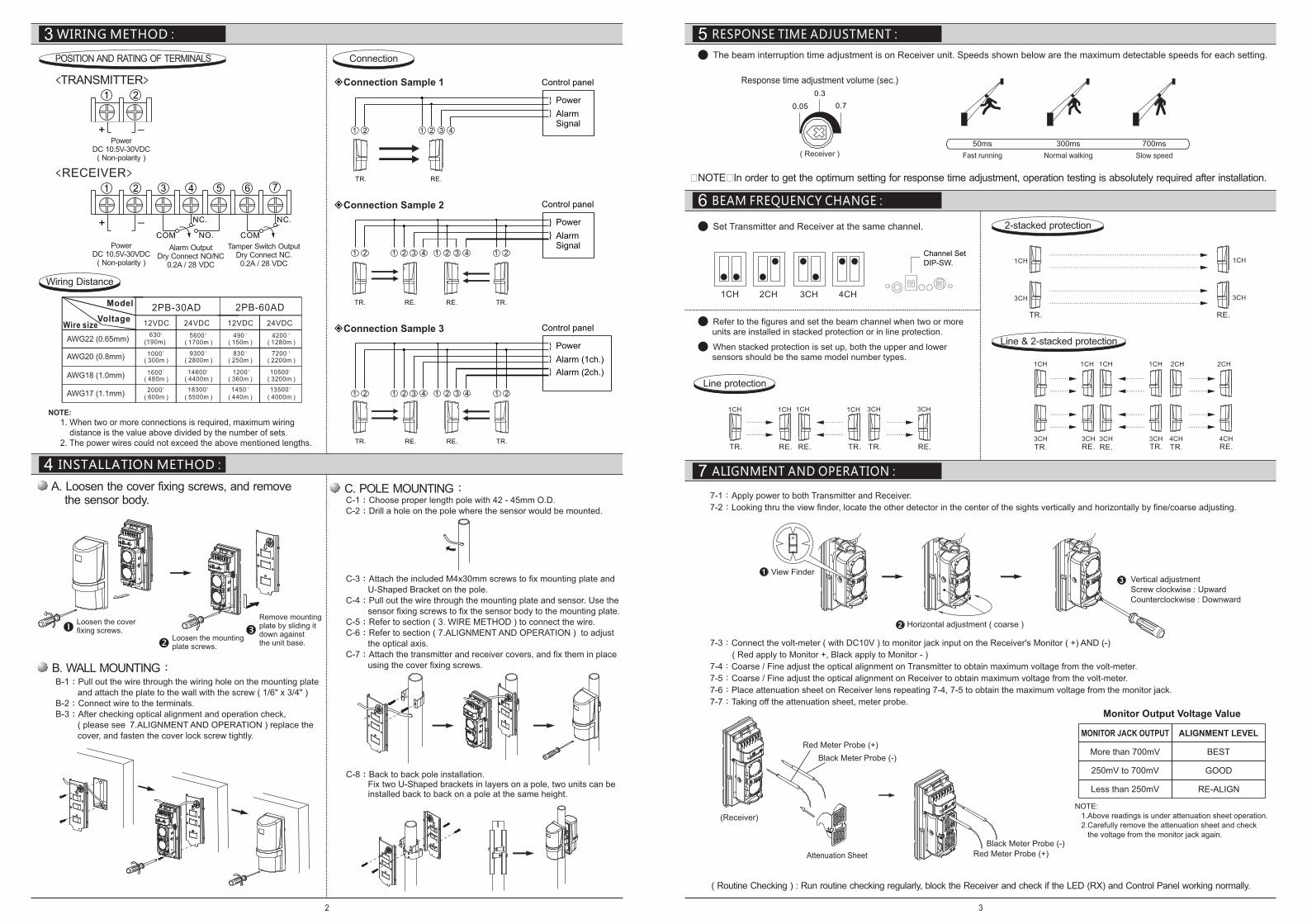
● Set Transmitter and Receiver at the same channel.
● Refer to the figures and set the beam channel when two or more units are installed in stacked protection or in line protection.
● When stacked protection is set up, both the upper and lower sensors should be the same model number types.
1CH 2CH 3CH 4CH
1CH
3CH
1CH
3CH
1CH 1CH 1CH 1CH 3CH 3CH
1CH 1CH 1CH 1CH 2CH 2CH
3CH 3CH 3CH 3CH 4CH 4CH
WIRING METHOD :
POSITION AND RATING OF TERMINALS
1 2
+ _
Power DC 10.5V-30VDC
( Non-polarity )
<TRANSMITTER>
<RECEIVER>1 2 3 4 5 6 7
COM COM
NC. NC.
NO.
+ _
Power DC 10.5V-30VDC
( Non-polarity )
Tamper Switch OutputDry Connect NC.0.2A / 28 VDC
Alarm OutputDry Connect NO/NC
0.2A / 28 VDC
NOTE:
1. When two or more connections is required, maximum wiring distance is the value above divided by the number of sets. 2. The power wires could not exceed the above mentioned lengths.
Wiring Distance
2PB-30AD 2PB-60AD
24VDC24VDC 12VDC
5600( 1700m )
' 490( 150m )
' 4200( 1280m )
'
9300( 2800m )
' 830( 250m )
' 7200( 2200m )
'
14600( 4400m )
' 1200( 360m )
' 10500( 3200m )
'
18300( 5500m )
' 1450( 440m )
' 13500( 4000m )
'
AWG22 (0.65mm)
AWG20 (0.8mm)
AWG18 (1.0mm)
AWG17 (1.1mm)
12VDC
630(190m)
'
1000( 300m )
'
1600( 480m )
'
2000( 600m )
'
Wire sizeVoltage
Model
Connection
TR. RE.
TR.
TR.
RE.
RE.
RE.
RE.
TR.
TR.
INSTALLATION METHOD :
A. Loosen the cover fixing screws, and remove the sensor body. C-1 Choose proper length pole with 42 - 45mm O.D. :
C-2 Drill a hole on the pole where the sensor would be mounted.:
C-3 Attach the included M4x30mm screws to fix mounting plate and : U-Shaped Bracket on the pole.C-4 Pull out the wire through the mounting plate and sensor. Use the: sensor fixing screws to fix the sensor body to the mounting plate. C-5 Refer to section ( 3. WIRE METHOD ) to connect the wire.:C-6 Refer to section ( 7.ALIGNMENT AND OPERATION ) to adjust: the optical axis.C-7 Attach the transmitter and receiver covers, and fix them in place: using the cover fixing screws.
C-8 Back to back pole installation. : Fix two U-Shaped brackets in layers on a pole, two units can be installed back to back on a pole at the same height.
RESPONSE TIME ADJUSTMENT :5
BEAM FREQUENCY CHANGE :6
ALIGNMENT AND OPERATION :7
0.70.05
0.3
Response time adjustment volume (sec.)
( Receiver )
50ms 300ms 700ms
Fast running Slow speedNormal walking
Channel Set DIP-SW.
Line protection
TR. RE. TR.RE. TR. RE.
2-stacked protection
TR. RE.
Line & 2-stacked protection
TR. RE. TR.RE. TR. RE.
7-1 :Apply power to both Transmitter and Receiver.
7-2 :Looking thru the view finder, locate the other detector in the center of the sights vertically and horizontally by fine/coarse adjusting.
7-3 :Connect the volt-meter ( with DC10V ) to monitor jack input on the Receiver's Monitor ( +) AND (-)
( Red apply to Monitor +, Black apply to Monitor - )
7-4:Coarse / Fine adjust the optical alignment on Transmitter to obtain maximum voltage from the volt-meter.
7-5:Coarse / Fine adjust the optical alignment on Receiver to obtain maximum voltage from the volt-meter.
7-6:Place attenuation sheet on Receiver lens repeating 7-4, 7-5 to obtain the maximum voltage from the monitor jack.
7-7:Taking off the attenuation sheet, meter probe.
( Routine Checking ) : Run routine checking regularly, block the Receiver and check if the LED (RX) and Control Panel working normally.
�NOTE�In order to get the optimum setting for response time adjustment, operation testing is absolutely required after installation.
Red Meter Probe (+)Black Meter Probe (-)
(Receiver)
Attenuation Sheet
Red Meter Probe (+)
Black Meter Probe (-)
1 View Finder
2 Horizontal adjustment ( coarse )
3 Vertical adjustmentScrew clockwise : UpwardCounterclockwise : Downward
C. POLE MOUNTING:
ŒLoosen the cover fixing screws.
�Loosen the mounting plate screws.
ŽRemove mountingplate by sliding it down against the unit base.
B. WALL MOUNTING:B-1 Pull out the wire through the wiring hole on the mounting plate: and attach the plate to the wall with the screw ( 1/6" x 3/4" )B-2 Connect wire to the terminals.:B-3 After checking optical alignment and operation check,: ( please see 7.ALIGNMENT AND OPERATION ) replace the cover, and fasten the cover lock screw tightly.
NOTE: 1. Above readings is under attenuation sheet operation. 2. Carefully remove the attenuation sheet and check the voltage from the monitor jack again.
Monitor Output Voltage Value
MONITOR JACK OUTPUT ALIGNMENT LEVEL
More than 700mV
250mV to 700mV
Less than 250mV
BEST
GOOD
RE-ALIGN
● The beam interruption time adjustment is on Receiver unit. Speeds shown below are the maximum detectable speeds for each setting.
2 3