Embed Size (px)
Citation preview
Navy Personnel Research and Development CenterSan Diego, California 92152-6800 TN-91-12 April 1991
AD-A236 411
Troubleshooting Assessmentand Enhancement (TAE) Program:
Design, Development,and Administration
Harry B. ConnerK; -Cathryn Poirier
Randy UlrichThomas Bridges
Approved for public release: distribution is unlimited.
9L1 5 15 0 44 91-00001.IIIIIEII HI
NPRDC-TN-91-12 April 1991Volume 1
Troubleshooting Assessment and Enhancement (TAE) Program:Design, Development, and Administration
Harry B. ConnerNavy Personnel Research and Development Center
Cathryn PoirierRandy Ulrich
Thomas Bridges Li. -System Engineering Associates
San Diego, CA 92109 " r
AV.JJ id/or- .
Approved and released by -- -
J. C. McLachlanDirector, Training Systems Department
Approved for public release;distribution is unlimited.
Navy Personnel Research and Development CenterSan Diego, California 92152-6800
Identification of specific equipment and software is for documentation only and does not implyendorsement.
c-tree is a trademark of FairCom.
Corvus, Corvus Systems, PCINOS, Netview, and Transporter are trademarks ofMedia Cybernetics, Inc.
Dr. Halo is a trademark of Media Cybernetics, Inc.
IBM and IBM PC are trademarks of International Business Machines Corp.
Meta WINDOW and MetaWINDOW/PLUS are trademarks of MetraphicsSoftware Corporation.
Microstat, Microsoft, MS-DOS are trademarks of Microsoft Corporation.
PANEL and PANEL Plus are trademarks of Roundhill Computer Systems Limited.
ZDS Microstat is a trademark of Zenith Data Systems.
ii
REPORT DOCUMENTATION PAGE Fom Approved
Public nportin burden for "hi collction of informati is amtmated to avenge I hour par respone. including thue c for reviewing inuarucdoti, mearding cuing dat soes. gatbeangand maintaining the data needed, and cornplating and reviewng the collection ofinfonmatiat. Sand commoat regarding this burden estimate orany odwo aspect ofthis collectiot ofifostionaincluding suggestions for reducing tis burder, to Washington HeadqtartmeraSvices. Directorate few Wnorn stionopeations and Rariu. 1215 Jeffero Davis Mhr~way. Suite 1 W)4. Ailing-ton. VA 22202-4302. ad to the office of Managrara and B udget. Paperwork Readuction Project M004-01185). Washtington., DC 20503.
1. AENC USEONL (Lave lan) 2 REPRT ATE3. REPORT TYPE AND DATE COVEREDTNI Apri 1991Technical Note--Oct 87-Mar 90
4. TITLE AND SUBTITLE 5. FUNDING NUMBERSTroubleshooting Assessment and ]Enhancement (TAE) Program: Design, 060372ON-RI772-ETOIDevelopment, and Administration
6. AUTHOR(S)Harry B. Conner. Cathryn Poirier, Randy Ulrich, Thomas Bridges
7. PERFORMING ORGANIZATION NAME(S) AND ADDRESS(ES) 8. PERFORMING ORGANIZATIONNavy Personnel Research and Development Center REPORT NUMBERSan Diego. California 92152-680 NPRDC-TN-91-.12
9. SPONSORING/MONITORING AGENCY NAME(S) AND ADDRESS(ES) 10. SPONSORINGMONITORINGChief of Naval Operations (OP-l11) AGENCY REPORT NUMBERNavy DepartmentWashington, DC 20350-2000
11. SUPPLEMENTARY NOTESVolume 2 contains the TAB delivery software on diskettes.For additional information, see NPRDC TN-91 -11 and NPRDC TN-91-13.
1 2a. DISTRIBUTION/AVAILABILITY STATEMENT 1 2b. DISTRIBUTION CODEApproved for public release; distribution is unlimited.
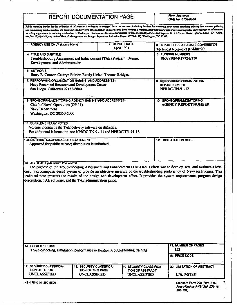
13. ABSTRACT (Maximum 200 words)The purpose of the Troubleshooting Assessment and Enhancement (TAB) R&D effort was to develop, test. and evaluate a low-
cost. microcomputer-based system to provide an objective measure of the troubleshooting proficiency of Navy technicians. Thistechnical note presents the results of the design and development effort. It provides the system requirements, program designdescription, TAB software, and the TAB administration guide.
14. SUBJECT TERMS 15. NUMBER OF PAGESTroubleshooting, simulation, performance evaluation, troubleshooting training 153
16. PRICE CODE
17. SECURITY CLASSIFICA- 18. SECURITY CLASSIFICA- 19. SECURITY CLASSIFICA- 20. LIMITATION OF ABSTRACTTION OF REPORT TION OF THIS PAGE TION OF ABSTRACTUNCLASSIFIED ( UNCLASSIFIED UNCLASSIFID UNLIMITED
NSN 75Q0-01-280-5500 Standard Form 298 (Rev. 2-89)Prescrbed b~y ANSI Sid Z39-IS298-102
FOREWORD
The troubleshooting Assessment and Enhancement (TAE) Program (previously tided Trouble-shooting Proficiency Evaluation Program, TPEP) was sponsored by the Deputy Chief of Naval Op-erations (OP-11) and was performed under 0603720N-R1772-ETO1. The purpose of the TAEprogram was to develop a low-cost, microcomputer-based system to provide an objective measureof the troubleshooting proficiency of Navy technicians.
This is the second of three technical notes that document the TAE program. The first technicalnote presents Lhe results of the literature search, a methodology for developing a troubleshootingproficiency evaluation system and the test and evaluation plan for the initial TAE system (Conner& Hassebrock,199 1). This technical note consists of two volumes. Volume 1 addresses the designand development of the computerized delivery system and a TAE administration guide. Volume 2contains the TAE delivery software on diskettes.
The final technical note presents the results of the test and evaluation as well as the conclusionsand recommendations for enhancing the TAE delivery system (Conner, Hartley, & Mark, 1991).
J. C. McLACHLANDirector, Training Systems Department
v
SUMMARY
Problem
The Navy has limited means of measuring the troubleshooting proficiency of Navy techniciansand their ability to contribute to operational readiness. Also, there is limited capability to maintainor enhance troubleshooting skills aboard ships or at Reserve Readiness Centers or to evaluate over-all troubleshooting capability. As a result, there is limited ongoing feedback to the training com-mand to improve the schools responsible for troubleshooting skills training.
Purpose
The purpose of the Troubleshooting Assessment and Evaluation (TAE) program was to developa low-cost, microcomputer-based system to provide an objective measure of the troubleshootingproficiency of Navy technicians. This report documents the design and development of the TAEdelivery system.
Approach
The approach was to construct a valid TAE test that would adequately sample thetroubleshooting domain. Using an "expert" model, a set of troubleshooting evaluation factors wasdeveloped. These factors were incorporated into the design and development of the computerizedTAE delivery system. The test and evaluation plan was designed to assess the TAE system, validatethe TAE troubleshooting episodes, and assess the reliability and effectiveness of the episodes inevaluating performance of troubleshooting technicians.
Results
The TAE effort produced a troubleshooting proficiency demonstration system for themaintainers (NEC ET-1453s) of the Naval Modular Automated Communications System (V)/Satellite Communications (NAVMAC (V)/SATCOM) hardware. The design and development ofthe TAE delivery system are described in terms of the system's functional requirements, theprogram design and installation, and administration requirements.
Conclusions and Future Efforts
The demonstration TAE system is currently implemented at the sites where the hardwaretraining is conducted. Although there are no plans to modify or expand the current TAE capability,several recommendations for improvement are provided.
vii
CONTENTS
Page
LNTRODUCTION ................................................................................................................ 1
Problem ........................................................................................................................... 1Purpose ............................................................................................................................ IBackground ..................................................................................................................... 2
APPROACH ......................................................................................................................... 2
Researc.h Objectives ........................................................................................................ 2Troubleshooting Evaluation Factors ............................................................................. 3TAE Episodes .................................................................................................................. 3
RESULTS ............................................................................................................................. 7
System Requirem ents ..................................................................................................... 7Program Design .............................................................................................................. 7Delivery Software ......................................................................................................... 7Administration G uide ...................................................................................................... 7
CONCLU SION S A ND FUTURE EFFORTS ...................................................................... 8
REFERENCES ..................................................................................................................... 9
APPENDIX A--TROUBLESHOOTING ASSESSMENT AND ENHANCEMENT(TAE) SYSTEM REQUIREMENTS DOCUMENT ...................................................... A-0
APPENDIX B--TROUBLESHOOTING ASSESSMENT AND ENHANCEMENT(TAE) PROGRAM DESIGN DESCRIPTION ............................................................... B-0
APPENDIX C--TROUBLESHOOTING ASSESSMENT AND ENHANCEMENT(TAE) SOFTW ARE DISKETTES: U SE ....................................................................... C-0
APPENDIX D--TAE ADMINISTRATION GUIDE ........................................................... D-0
ix
INTRODUCTION
Problem
Currently the Navy has limited means to objectively measure the troubleshooting proficiencyof shipboard technicians and their ability to contribute to operational readiness. Other thansubjective supervisory opinion, there is no consistent and reliable way to assess the transfer oftraining, particularly hands-on training on hardware systems provided in Navy "C" schools. Oncethe "C" school graduate has been integrated into the ship's force, fleet commanders have noobjective method to assess the technician's performance capabilities or skill degradation over time.In addition, the schools receive no quantifiable feedback identifying specific areas wheretroubleshooting training requires greater emphasis or improvement.
Due to limited availability of system hardware at "C" schools, actual hands-on training time isseverely restricted. This limits the amount of time students explicitly use their system knowledgeand, therefore, decreases the effectiveness of instructional programs. Once on-board, the shipsafety hazards associated with corrective maintenance of weapon system hardware preclude theuse of drill and practice exercises. This limits the technician's ability to maintain or improvetroubleshooting skills.
Purpose
The purpose of the Troubleshooting Assessment and Evaluation (TAE) program was to developa low-cost, microcomputer-based system to provide an objective measure of the troubleshootingproficiency of Navy technicians.
Specifically, the TAE program was to (1) assess personnel troubleshooting capabilities withinthe Navy training environment (e.g., "C" school and/or reserve training activities), (2) develop drilland practice for personnel in training awaiting hardware availability or active duty assignments,(3) improve curricula and training methods based on school troubleshooting assessment results, (4)provide fleet and reserve on-board training (OBT) through drill and practice exercises, (5) developan objective measure of operational readiness of fleet ad reserve personnel in their area of systemshardware troubleshooting capability, (7) improve operational readiness, and (8) improve curriculaand instructional methods as a result of operational fleet and reserve feedback of assessment/evaluation data to the training community.
The TAE project resulted in a troubleshooting proficiency assessment demonstration for thehigh-technology (electronic/digital) maintainer community (NEC ET- 1453) for the Naval ModularAutomated Communications System (V)/Satellite Communications (NAVMACS (V)/SATCOM)hardware. Th!% technical note documents the design and development of the TAE computerizeddelivery system. The test and evaluation will (1) assess the TAE troubleshooting evaluation anddiagnosu. factors, (2) validate the ability of the TAE episodes to evaluate and diagnosetroubleshooting proficiency, and (3). assess the reliability and effectiveness of the TAE episodes toe-vaiuate troubleshooting proficiency, diagnose results, and, thereby, lead to improved training.
Background
The TAE project was organized into three phases: analysis, design and development, and testand evaluation. The steps included:
1. Selection of the NAVMACS (V)/SATCOM hardware system and the NEC ET-1453maintainer community for the demonstration.
2. Review of the literature to provide input into the design and development of thetroubleshooting episodes and the test and evaluation procedures.
3. Design and development of computer software to support the evaluation program.
4. Design and development of the troubleshooting episodes selected as representative for thedemonstration maintenance community.
5. Design and development of training assessment and training drill and practice episodes.
6. Design and development of a troubleshooting episode development capability to be usedfor other hardware systems.
7. Development of factors for evaluating troubleshooting proficiency.
8. Development of a test and evaluation plan stating the research hypotheses and analysistechniques.
9. Data collection, analysis, and reporting for the test and evaluation.
The TAE system computer software design and development efforts (Steps 3 through 6) aredescribed in this technical note. The review of literature and a discussion of the theoretical andmethodological issues in TAE design (Steps 1 and 2) are documented in Conner and Hassebrock(1991). The results of the test and evaluation (Steps 7, 8, and 9) are presented in Conner, Hartley,and Mark (1991).
APPROACH
Research Objectives
To develop the capability to discriminate between levels of troubleshooting proficiency, it wasnecessary to L.tfine the delivery system requirements within the TAE context. This effort proposedto use fleet subject matter experts and instructor ratings of TAE scoring profiles to construct atroubleshooting proficiency criterion. Once developed, this measure could be refined over time toproduce a closer approximation of the ultimate criterion of troubleshooting proficiency. If theconcepts of reliability and validity were established, then it would be possible to build a strong,logical connection between TAE and its ability to predict troubleshooting proficiency amongelectronics technicians in the fleet.
2
Whether TAE could be empirically validated as a predictive instrument for success in the "C"school program by using the various "C" school test scores as criterion measures was problematicat the time the delivery system was being designed and developed. However, it was assumed thatthe TAE test could accurately estimate actual performance capability at the time of "C" schoolgraduation as well as predict subsequent fleet performance.
The manner in which the TAE test was constructed had to be logical and sensible. That is, theTAE test must have face validity. It was also imperative that the hardware system being used as thebasis for the test was adequately sampled and developed into troubleshooting episodes (items). Thetroubleshootiag episodes developed for the NAVMACS (V)/SATCOM hardware encompass thetroubleshooting domain for the equipment and reflect actual equipment faults that technicians mayencounter in the fleet.
Troubleshooting Evaluation Factors
The development of the evaluation factors utilized an "expert" model. That is, the experts inthe field of endeavor under question generally define and stipulate the contents of the test (i.e., thetest items or events), the relative value of the events, and the method of scoring. Given that theexperts have determined the test to be given, the components of the test, and the method ofweighing and scoring the events of the test, it is difficult to take issue with the ultimate results ofindividuals being measured by the standards established.
Development of the TAE troubleshooting evaluation factors followed a similar "expert"defined approach. Based on previous research findings (Conner, 1986, 1987) and inputs fromsubject matter experts, a questionnaire concerning factors related to the evaluation oftroubleshooting skills was developed and disseminated to high-technology maintenance personnelin technical environments and in the fleet. Respondents were asked to complete a backgroundinformation form and then rank order the factors in order of importance. Since the relativeimportance of the factors may change with conditions, the following conditions were assumed: (1)non-combat, (2) normal day in home port, and (3) fault was encountered during a normal systemscheck. The responses were tabulated and ranked.
A second questionnaire was developed and disseminated to subject matter experts to rank thefactors according to their relative level of importance. The results were tabulated and converted toweighting factors to be used in evaluating an individual's performance. The final weights were theones utilized in the TAE computerized scoring scheme for the test and evaluation. The TAEdelivery system was designed such that the troubleshooting evaluation environment can easily bechanged. Also, factors may be added, deleted, or modified and weights assigned to the variousfactors may be changed by the user.
TAE Episodes
Within the context of the TAE demonstration, troubleshooting is viewed as part of thecorrective maintenance function. When a system is not functioning properly, correctivemaintenance must be performed to return the system to an optimum operational state.Troubleshooting is the means by which the faulty components are identified. Once identified, the
3

faulty components can be repaired/replaced. Figure 1 displays this relationship. The TAE enisodeswere designed to measure the ability to troubleshoot by identifying the faulty component.
HARDWARE SYSTEM INTERACTIONS
I I I ICONSTRUCT INSTALL OPERATE MAINTAIN
PREVENTIVE CORRECTIVEMAINTENANCE MAINTENANCE
I ITROUBLESHOOTING REPAIR
Figure 1. Hardware activity to troubleshooting.
The TAE testing format begins by displaying fault indicators. The subject uses a series ofmenus to review fault symptoms, front panels, maintenance panels, and diagnostic information; toselect equipment; and to make reference designator tests or replace a Lowest Replaceable Unit(LRU). The subject's goal in the TAE test is to find the faulty LRU as defined by the maintenancephilosophy of the system. This is done by selecting the suspected LRU for replacement. It ispossible for the fault symptom to logically lead to an LRU that is not the faulty LRU as defined bythe episode. This is indicated as a GOOD FAULT but not the specific faulty LRU.
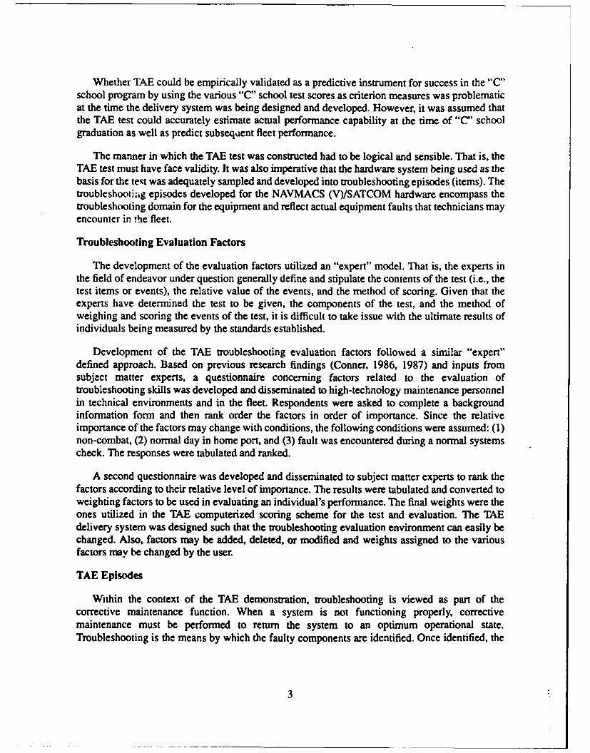
The troubleshooting assessment episodes are listed below. No TAE episodes were developedfor troubleshooting the TSEC/KG-36 due to the sensitivity and classification problems associatedwith this subsystem.
ANIUSH-26 (V) Subsystem1. Formatter A2. Form tier B3. Servo/Data4. Parallel Interface5. Control
AN/USQ-69 (V) Subsystem1. Maintenance Panel Keyboard2. Power Supply
4
3. CRT4. 2nd, 3rd Page RAM5. Micro Controller
AN/UYK-20 (V) Subsystem1. Channel 16 Interface2. Micro Channel 15 and 10 Oneshot Control3. Channel 14 Interface4. Memnory Interface5. Memory Interface
CV-3333/U Subsystem1. Sample Processor Assembly2. Sample Data Generator Assembly3. Spectrum Analyzer No. 24. Handset5. Analyzer and Synthesizer Analog6. Voicing and Channel Encoder7. Pitch Analyzer8. Spectrum Analyzer No. 29. Timing and Interface10. Timing and Self Test
ON-143 (V)/USQ Subsystem1. Level Converter2. Transmit Sequence Control3. Relay Card4. Rec Synchronization5. Red/Black Interface6. Red/Black Interface Relay
RD-397U Subsystem1. Punch Enable Signal2. LD Signal3. OD 3 Signal
TT-624 (V) $/UG Subsystem1. Input and Buffer Data Registers2. Hammer Drivers3. Paper Feed Control Logic4. Output Decode5. Serial Interface Logic
The TAE testing episodes developed for the demonstration may be used as troubleshootingtraining exercises as well as troubleshooting assessment tools. There are five demonstrationsystems at the Fleet Training Center, Norfolk and six demonstration systems at the Advanced
5
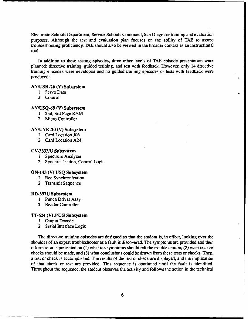
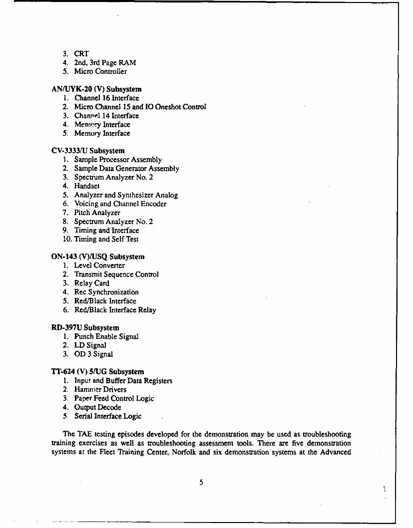
Electronic Schools Department, Service Schools Command, San Diego for training and evaluationpurposes. Although the test and evaluation plan focuses on the ability of TAE to assesstroubleshooting proficiency, TAE should also be viewed in the broader context as an instructionaltool.
In addition to these testing episodes, three other levels of TAE episode presentation wereplanned: directive training, guided training, and test with feedback. However, only 14 directivetraining episodes were developed and no guided training episodes or tests with feedback wereproduced:
AN/USH.26 (V) Subsystem1. Servo Data2. Control
AN/USQ-69 (V) Subsystem1. 2nd, 3rd Page RAM2. Micro Controller
AN/UYK-20 (V) Subsystem1. Card Location J062. Card Location A24
CV-3333/U Subsystem1. Spectrum Analyzer2. Synchrc 'zation, Control Logic
ON-143 (V) USQ Subsystem1. Rec Synchronization2. Transmit Sequence
RD-397U Subsystem1. Punch Driver Assy2. Reader Controller
TT-624 (V) 5/UG Subsystem1. Output Decode2. Serial Interface Logic
The directive training episodes are designed so that the student is, in effect, looking over theshoulder of an expert troubleshooter as a fault is discovered. The symptoms are provided and theninformati; ,n is presented on (I) what the symptoms should tell the troubleshooter, (2) what tests orchecks should be made, and (3) what conclusions could be drawn from these tests or checks. Then,a test or check is accomplished. The results of the test or check are displayed, and the implicationof that check or test are provided. This sequence is continued until the fault is identified.Throughout the sequence, the student observes the activity and follows the action in the technical
6
manuals (TMs). Information and graphics from the TMs are provided in the presentation as
appropriate.
RESULTS
System Requirements
The TAE system was designed by a team of experts. Training specialists, subject matterexperts, and software developers defined the requirements for development of a low-costassessment tocki which could also be used for training drill and practice. To lower costs, the systemwas to use off-the-shelf technology as much as possible. The intent of the project was to expandthe TAF appr'ach, not the utilization of hardware technology. The TAE troubleshooting episodeswere designed to be low fidelity simulations to reduce the computer hardware and softwareprogramming requirements. However, within this construct, it was important to make theassessment approach as flexible as possible and to ensure that the delivery system was user friendlyfrom the perspective of the students and the administrators. Appendix A presents the TAE SystemRequirements Document (SRD). The SRD provides a detailed description of the functionalrequirements of the TAE computerized delivery system.
Program Design
Appendix B provides a detailed description of the TAE software as it was designed anddeveloped for the NAVMACS (V)/SATCOM demonstration. This information is intended to allowthe user to expand or improve the current delivery system or modify the computerized program fora different hardware system. The program description is presented from the perspective of asoftware developer who is familiar with the concepts of software design. It includes data flowdiagrams, data dictionaries, context diagrams, and other commonly used computer software tools,as documented in DeMarco (1978).
Delivery Software
Volume 2 (of this technical note) contains the TAE delivery software on diskettes. Appendix Cprovides instructions for installing the TAE software at activities that have the computers to run theprogram. Information is also included on the program structure and tools so that a qualifiedprogrammer can modify or improve the demonstration software, or use the programming as a pointof departure in the development of a software package for a new hardware system.
Administration Guide
Appendix t) provides the TAE Administration Guide that was developed for use in the test andevaluation of the NAVMACS (V)/SATCOM demonstration. There have been some improvementsin the delivery system functions since the guide was prepared. These improvements are describedin the TAE SRD (Appendix A) and included in the delivery software (Volume 2).
7
CONCLUSIONS AND FUTURE EFFORTS
At this time, the TAE system is implemented at the two sites where NAVMACS (V)/SATCOMhardware training is conducted: the Advanced Electronics Schools Department, Service SchoolsCommand, Naval Training Center, San Diego, California and the Fleet Training Center, Norfolk,Virginia. The system has also been installed on the Mobile Pierside Trainers, Naval Station, SanDiego, California.
Although there are no plans to modify or expand the current TAE capability, severalrecommendations for future improvements are provided below. Recommendations based on theresults of the test and evaluation are reported in Conner, Hartley, and Mark (1991).
1. A networking capability would be useful in the classroom or Reserve Readiness Centerenvironment.
2. The software should be made to recognize typographical errors in "Reference Designation"rather than to record them as out of bounds.
3. The episode authoring capability should be expanded so that subject matter experts canmore readily develop and implement a wide range of troubleshooting exercises.
4. The analysis approach for the test and evaluation, which did not deal specifically withissues of interest to Navy "C" schools, should be expanded to evaluate issues related tocurriculum standards, control, and improvement.
5. Additional TAE troubleshooting episodes to provide directive training, guided training, andtests with feedback should be developed. Then, a complete and comprehensivetroubleshooting skill development, maintenance, assessment, and evaluation programwould be available for personnel from the novice to expert skill levels for use by active dutypersonnel in the school or fleet environments and by reserve personnel at the readinesscenters or aboard ship during active duty periods.
8
REFERENCES
Conner, H. B. (1986, October). Troubleshooting proficiency evaluation project (TPEP). InProceedings of Military Testing Association Conference, Mystic, Connecticut.
Conner, H. B. (1987, April). Troubleshooting proficiency evaluation project (TPEP) for the NATOSeasparrow Surface Missile system (NSSMS). In Proceedings of First InternationalManpowe, and Training Conference of the National Security Industrial Association,Luxembourg.
Conner, H B.. & Hassebrock, F. E. (1991). Troubleshooting Assessment and Enhancement (TAE)program: Theoretical, methodological, and test and evaluation issues (TN-91-1 1). San Diego:Navy Personnel Research and Development Center.
Conner, H. B., Hartley, S., & Mark, L. J. (1991). Troubleshooting Assessment and Enhancement(TAE) program: Test and evaluation (TN-91-13). San Diego: Navy Personnel Research andDevelopment Center.
DeMarco, T. (1978). Structured analysis and system specification. New York: Yourdon.1
'Also cited in Appendix B.
9
APPENDIX A
TROUBLESHOOTING ASSESSMENT AND ENHANCEMENT (TAE)SYSTEM REQUIREMENTS DOCUMENT
Page
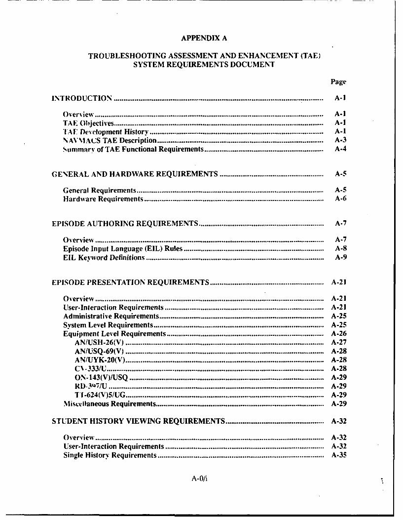
INTRODUCTION................................................................................. A-1
Overview ..................................................................................... A-ITAE Objectives................................................................................A-ITAF Development History................................................................... A-INANAMACS TAE Description ................................................................ A-3Summary of TAE Functional Requirements .............................................. A-4
GENERAL AND HARDWARE REQUIREMENTS......................................... A-5
General Requirements........................................................................ A-5Hardware Requirements ..................................................................... A-6
EPISODE AUTHORING REQUIREMENTS ................................................ A-7
Overview%...................................................................................... A-7Episode In put Language (EIL) Rules ...................................................... A-8EIL Keyword Definitions .................................................................... A-9
EPISODE PRESENTATION REQUIREMENTS............................................ A-21
Overview..................................................................................... A-21User-Interaction Requirements............................................................. A-21Administrative Requirements............................................................... A-25System Level Requirements ................................................................. A-25Equipment Level Requirements ............................................................ A-26
ANIUSH-26(V)............................................................................ A-27AN/USQ-69(V)............................................................................ A-28ANI/UYK-20(V)............................................................................ A-28CN*333/U ................................................................................. A-28ON-143(V)/USQ .......................................................................... A-29RD-3u7/U ................................................................................. A-29TI -624(V)5IUG............................................................................ A-29
Miscellaneous Requirements ................................................................ A-29
STUDENT HISTORY VIEWING REQUIREMENTS...................................... A-32
Overview ..................................................................................... A-32User-Interaction Requirements............................................................. A-32Single History Requirements................................................................A-35
A-Ohi
Displaying and Printing Student Histories ............................................................ A-35Displaying and Printing a Summarized Analysis ...................... A-37Deleting a Student History ........................... A-42Editing Data In a Student History .......................................................................... A-42
Multiple History Requirements .................................................................................... A-43Multiple Scoring Requirements ..................... A-43
Display Student Final Scores .... *............ ................ A-43Display Class Average ............................................................................................ A.44
Management Requirements .................................................................................... A-45Authoring Scoring Constants .................. A-46Archiving Student History Databases........................................................... A-46Combine Student History Databases ..................................................................... A-47Transfer Student History Database to Diskette ......................... A-48Format for Statistics .. ............ ........... ................................................. A-48Delete Student from Database ................................................................................ A-50
LOCAL AREA NETWORK REQUIREMENTS ............................. A-S0
LIST OF TABLES
A-i. Definition of Keywords in the Episode Overview Section ................................ A-10A-2. Definition of Keywords in the System-Level Section ....................................... A-i1A-3. Definition of Keywords in the Equipment-Specific Section .............................. A-13A-4. TAE Event Types in the Student History Database ..................... A-33A-5. Scoring Maximums ............................................................................................. A-40A-6. Scoring W eights ..................................................................................................... A -41
LIST OF FIGURES
A-I. TAE System Context Diagram ............................................................................ A-2A-2. NAVMACS System Diagram ............................................................................... A-3A-3. Levels of Analysis for the NAVMACS TAE System ................ A-4A-4. NAVMACS Episode Authoring System .................... A-7A-5. PRESENT Menu Hierarchy for Main Menu and System Level Menu .......... A-22A-6. PRESENT Menu Hierarchy for Equipment-Specific Tests......_.... A-23A-7. Episodes Completed Record ................................. ...... . A-31A-8. EDITVIEW Menu HieAa-chy ............ .. A.34A-9. Sequence of Troubleshooting Events.................................. A.36A-10. Revised Sequence of Events ............................. A-37A.11. Example of a Scored Analysis ................................. A.37A-12. Data Dependencies for Scored Analysis ........................ A-39A-13. Final Scores Display for One Student ................................................................ A-44A.14. EDITVIEW Administrative Menu .................................................................... A-45A-IS. Student History Organization .............................................................................. A-47
A-O/ii
INTRODUCTION
Overview
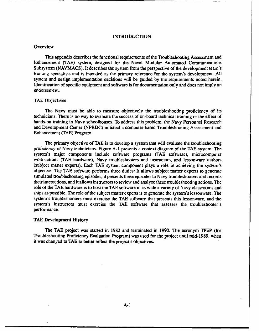
This appendix describes the functional requirements of the Troubleshooting Assessment andEnhancement (TAE) system, designed for the Naval Modular Automated CommunicationsSubsystem (NAVMACS). It describes the system from the perspective of the development team'straining specialists and is intended as the primary reference for the system's development. Allsystem and cesign implementation decisions will be guided by the requirements noted herein.Identification of specific equipment and software is for documentation only and does not imply anendorsement.
TA E Objectives
The Navy must be able to measure objectively the troubleshooting proficiency of itstechnicians. There is no way to evaluate the success of on-board technical training or the effect ofhands-on training in Navy schoolhouses. To address this problem, the Navy Personnel Researchand Development Center (NPRDC) initiated a computer-based Troubleshooting Assessment andEnhancement (TAE) Program.
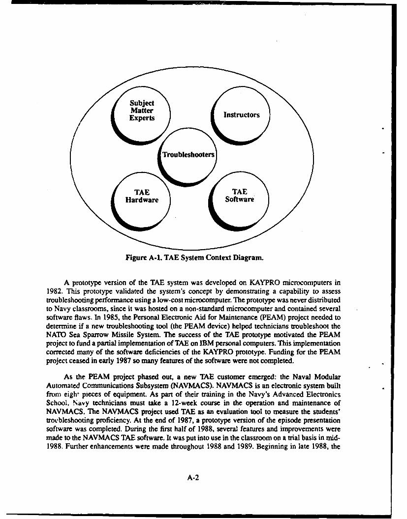
The primary objective of TAE is to develop a system that will evaluate the troubleshootingproficiency of Navy technicians. Figure A-1 presents a context diagram of the TAB system. Thesystem's major components include software programs (TAE software), microcomputerworkstations (TAE hardware), Navy troubleshooters and instructors, and lessonware authors(subject matter experts). Each TAE system component plays a role in achieving the system'sobjective. The TAE software performs three duties: It allows subject matter experts to generatesimulated troubleshooting episodes, it presents these episodes to Navy troubleshooters and recordstheir interactions, and it allows instructors to review and analyze these troubleshooting actions. Therole of the TAE hardware is to host the TAE software in as wide a variety of Navy classrooms andships as possible. The role of the subject matter experts is to generate the system's lessonware. Thesystem's troubleshooters must exercise the TAE software that presents this lessonware, and thesystem's instructors must exercise the TAE software that assesses the troubleshooter'sperformance.
TAE Development History
The TAE project was started in 1982 and terminated in 1990. The acronym TPEP (forTroubleshooting Proficiency Evaluation Program) was used for the project until mid-1989, whenit was changed to TAE to better reflect the project's objectives.
A-1
Subject
M atterI n t u orExpertsIntuor
l'roTroubleshooters)
TAE TAE
Hardware Software
Figure A-I. TAE System Context Diagram.
A prototype version of the TAE system was developed on KAYPRO microcomputers in1982. This prototype validated the system's concept by demonstrating a capability to assesstroubleshooting performance using a low-cost microcomputer. The prototype was never distributedto Navy classrooms, since it was hosted on a non-standard microcomputer and contained severalsoftware flaws. In 1985, the Personal Electronic Aid for Maintenance (PEAM) project needed todetermine if a new troubleshooting tool (the PEAM device) helped technicians troubleshoot theNATO Sea Sparrow Missile System. The success of the TAE prototype motivated the PEAMproject to fund a partial implementation of TAE on IBM personal computers. This implementationcorrected many of the software deficiencies of the KAYPRO prototype. Funding for the PEAMproject ceased in early 1987 so many features of the software were not completed.
As the PEAM project phased out, a new TAE customer emerged: the Naval ModularAutomated Communications Subsystem (NAVMACS). NAVMACS is an electronic system builtfrom eigh pieces of equipment. As part of their training in the Navy's Advanced ElectronicsSchool, Navy technicians must take a 12-week course in the operation and maintenance ofNAVMACS. The NAVMACS project used TAE as an evaluation tool to measure the students'troLbleshooting proficiency. At the end of 1987, a prototype version of the episode presentationsoftware was completed. During the first half of 1988, several features and improvements weremade to the NAVMACS TAE software. It was put into use in the classroom on a trial basis in mid-1988. Further enhancements were made throughout 1988 and 1989. Beginning in late 1988, the
A-2
NAVMACS TAE software was employed to collect student troubleshooting data for analysis.Analysis of the data was begun in mid-1989 and completed in early 1990.
NAVMACS TAE Description
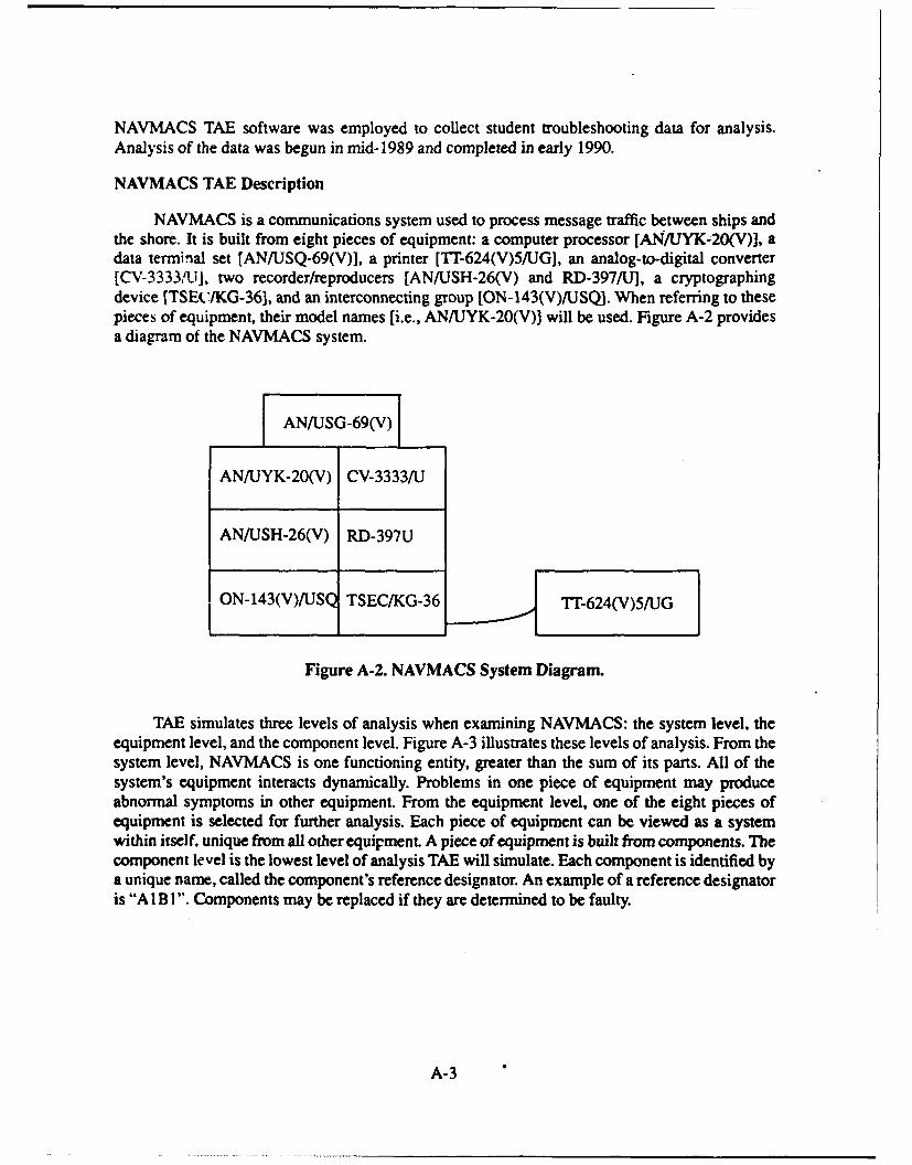
NAVMACS is a communications system used to process message traffic between ships andthe shore. It is built from eight pieces of equipment: a computer processor [AN/UYK-20(V)I, adata terminal set [AN/USQ-69(V)], a printer [Tr-624(V)5/UG], an analog-to-digital converter[CV-3333,'ti], two recorder/reproducers [AN/USH-26(V) and RD-397/U], a cryptographingdevice [TSE(IKG-36, and an interconnecting group [ON-143(V)/U SQ]. When referring to thesepieces of equipment, their model names [i.e., AN/IJYK-20(V)] will be used. Figure A-2 providesa diagram of the NAVMACS system.
AN/USG-69(V)
AN/UYK-20(V) CV-3333/U
AN/USH-26(V) RD-397U
ON-143(V)/IUSQ TSEC/KG-36 TT-624(V)5/UG
Figure A-2. NAVMACS System Diagram.
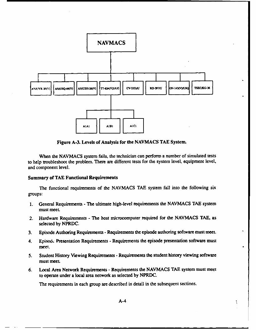
TAE simulates three levels of analysis when examining NAVMACS: the system level, theequipment level, and the component level. Figure A-3 illustrates these levels of analysis. From thesystem level, NAVMACS is one functioning entity, greater than the sum of its parts. All of thesystem's equipment interacts dynamically. Problems in one piece of equipment may produceabnormal symptoms in other equipment. From the equipment level, one of the eight pieces ofequipment is selected for further analysis. Each piece of equipment can be viewed as a systemwithin itself, unique from all other equipment. A piece of equipment is built from components. Thecomponent level is the lowest level of analysis TAE will simulate. Each component is identified bya unique name, called the component's reference designator. An example of a reference designatoris "A 1B I". Components may be replaced if they are determined to be faulty.
A-3
NAVMACS
AlI DI Ii
Figure A-3. Levels of Analysis for the NAVMACS TAE System.
When the NAVMACS system fails, the technician can perform a number of simulated teststo help troubleshoot the problem. There are different tests for the system level, equipment level,and component level.
Summary of TAE Functional Requirements
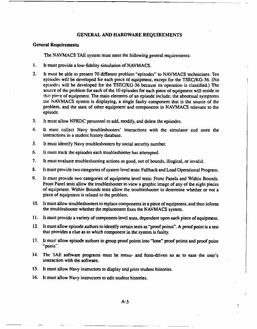
The functional requirements of the NAVMACS TAE system fall into the following sixgroups:
1. General Requirements - The ultimate high-level requirements the NAVMACS TAE systemmust meet.
2. Hardware Requirements - The host microcomputer required for the NAVMACS TAE, asselected by NPRDC.
3. Episode Authoring Requirements - Requirements the episode authoring software must meet.
4. Episod.: Presentation Requirements - Requirements the episode presentation software mustmeet.
5. Student History Viewing Requirements - Requirements the student history viewing softwaremust meet.
6. Local Area Network Requirements - Requirements the NAVMACS TAE system must meetto operate under a local area network as selected by NPRDC.
The requirements in each group are described in detail in the subsequent sections.
A-4
GENERAL AND HARDWARE REQUIREMENTS
General Requirements
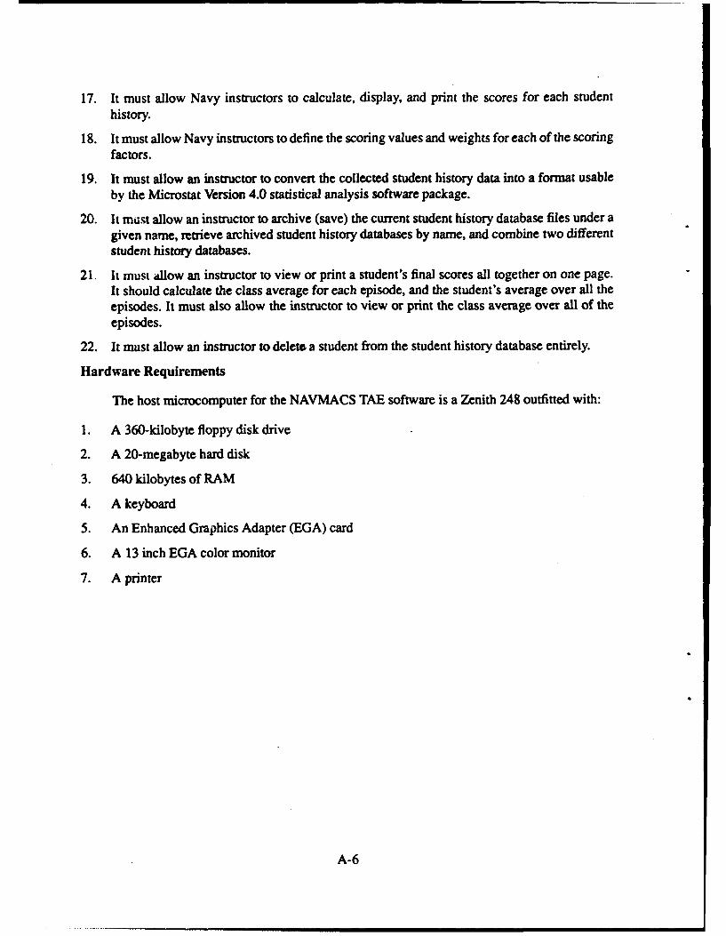
The NAVMACS TAE system must meet the following general requirements:
1. It must provide a low-fidelity simulation of NAVMACS.
2. It must be able to present 70 different problem "episodes" to NAVMACS technicians. Tenepisodes will be developed for each piece of equipment, except for the TSECIKG-36. (Noepisodes will be developed for the TSEC/KG-36 because its operation is classified.) Thesource of the problem for each of the 10 episodes for each piece of equipment will reside inthat piere of equipment. The main elements of an episode include: the abnormal symptomsthe NAVMACS system is displaying, a single faulty component that is the source of theproblem, and the state of other equipment and components in NAVMACS relevant to theepisode.
3. It must allow NPRDC personnel to add, modify, and delete the episodes.
4. It must collect Navy troubleshooters' interactions with the simulator and store theinteractions in a student history database.
5. It must identify Navy troubleshooters by social security number.
6. It must track the episodes each troubleshooter has attempted.
7. It must evaluate troubleshooting actions as good, out of bounds, illogical, or invalid.
8. It must provide two categories of system level tests: Fallback and Load Operational Program.
9. It must provide two categories of equipment level tests: Front Panels and Within Bounds.Front Panel tests allow the troubleshooter to view a graphic image of any of the eight piecesof equipment. Within Bounds tests allow the troubleshooter to determine whether or not apiece of equipment is related to the problem.
10. It must allow troubleshooters to replace components in a piece of equipment, and then informthe troubleshooter whether the replacement fixes the NAVMACS system.
11. It must provide a variety of component-level tests, dependent upon each piece of equipment.
12. It must allow episode authors to identify certain tests as "proof points". A proof point is a testthat provides a clue as to which component in the system is faulty.
13. It mus! allow episode authors to group proof points into "lone" proof points and proof point"pools".
14. The 'IAE software programs must be menu- and form-driven so as to ease the user'sinteraction with the software.
15. It must allow Navy instructors to display and print student histories.
16. It must allow Navy instructors to edit student histories.
A-5
17. It must allow Navy instructors to calculate, display, and print the scores for each studenthistory.
18. It must allow Navy instructors to define the scoring values and weights for each of the scoringfactors.
19. It must allow an instructor to convert the collected student history data into a format usable
by the Microstat Version 4.0 statistical analysis software package.
20. It mist allow an instructor to archive (save) the current student history database files under agiven name, retrieve archived student history databases by name, and combine two differentstudent history databases.
21. It must allow an instructor to view or print a student's final scores all together on one page.It should calculate the class average for each episode, and the student's average over all theepisodes. It must also allow the instructor to view or print the class average over all of theepisodes.
22. It must allow an instructor to deleta a student from the student history database entirely.
Hardware Requirements
The host microcomputer for the NAVMACS TAE software is a Zenith 248 outfitted with:
1. A 360-kilobyte floppy disk drive
2. A 20-megabyte hard disk
3. 640 kilobytes of RAM
4. A keyboard
5. An Enhanced Graphics Adapter (EGA) card
6. A 13 inch EGA color monitor
7. A printer
A-6
EPISODE AUTHORING REQUIREMENTS
Overview
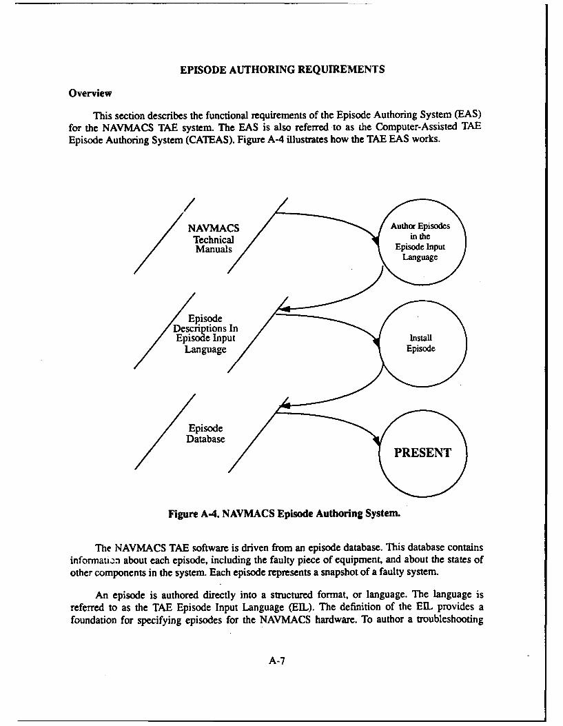
This section describes the functional requirements of the Episode Authoring System (EAS)for the NAVMACS TAE system. The EAS is also referred to as the Computer-Assisted TAEEpisode Authoring System (CATEAS). Figure A-4 illustrates how the TAE EAS works.
/NAVMACS Auhr/psoe
Technical inth
Epi .sode
Languagee
/Episode
Dtabase
Figure A-4. NAVMACS Episode Authoring System.
The NAVMACS TAE software is driven from an episode database. This database containsinformati-n about each episode, including the faulty piece of equipment, and about the states ofother components in the system. Each episode represents a snapshot of a faulty system.
An episode is authored directly into a structured format, or language. The language isreferred to as the TAE Episode Input Language (EEL). The definition of the EIL provides afoundation for specifying episodes for the NAVMACS hardware. To author a troubleshooting
A-7
episode, the lesson developer uses a raw text editor (vi or Wordstar in non-document mode) to writean episode in the EIL, then installs the episode into the episode database.
To process the EL files and maintain the episode database, the following programs(authoring tools) have been created:
1. Episode Database Creation Program (CREATEDB) - Creates the episode and student historydata..ases. The databases must be created before any episodes or student histories can beaddeJ to the databases.
2. Episode Installation Program (ADDEP) - Installs an episode into the episode database oncethe sLructure of the episode database has been defined. The episode must be written in the EL
3. Episode Deletion Program (DELEP) - Deletes an episode from the episode database.
Episode Input Language (EIL) Rules
The EIL syntax and semantic rules are as follows:
I. An episode is divided into three sections: Episode Overview, System-Level Information, andEquipment-Specific information.
The episode overview is mandatory; system-level information and equipment-specificinformation are optional. The order indicated above must be respected: the episode overviewis placed before the system-level information; the system-level information is placed beforethe equipment-specific information. For a section that is optional, the defined defaults will beused when that section is not specified.
2. The EL is built from a set of keywords.
Keywords are case-insensitive: They can be in uppercase or lowercase (this document willalways print keywords in uppercase). Keywords are used to begin sections and commands.
3. The keywords beginning the three sections are OVERVIEW, SYSTEM-LEVEL, andEQUIPMENT-SPECIFIC.
4. Anything after a semicolon is a comment; a semicolon can appear anywhere on a line.
Here is a typical outline of an episode definition:
This is the first line of the episode definition.Comments appear after semicolons.
: The _irst section in an episode definition is the overview. The overview is signaled by theOVERVIEW keyword.
OVERVIEW
Episode overview information would be placed here!!See below for the contents of the overview section.
A-8
; The next section is system-level information, signaled by the SYSTEM-LEVEL; keyword.
SYSTEM-LEVEL
System-level information is placed here.
The last section is equipment-specific information, signaled by the keywordEQ TIPMENT-SPEClIC.
EQUIPMENT-SPECIFIC
Equipment-specific information is placed here.
End of episode definition!
5. Data is assigned to a keyword with the equal sign (=).
6. Aside from keywords, comments, and =, the onlv other tokens that can occur in an episodedefinition must represent data. When a datum is character string, it must be enclosed inquotes.
EIL Keyword Definitions
The definitions of the EIL keywords are presented in 'lables A-i, A-2, and A-3. Table A-Idefines the keywords in the episode overview section. Table A-2 defines the keywords in thesystem-level section. Table A-3 defines the keywords in the equipment-specific section.
A-9
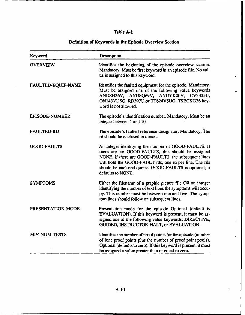
Table A-1
Definition of Keywords in the Episode Overview Section
Keyword Description
OVERVIEW Identifies the beginning of the episode overview section.Mandatory. Must be first keyword in an episode file. No val-ue is assigned to this keyword.
FAULTED-EQUIP-NAME Identifies the faulted equipment for the episode. Mandatory.Must be assigned one of the following value keywordsANUSH26V, ANUSQ69V, ANUYK20V, CV3333U,ON143VUSQ, RD397U,or TT624V5UG. TSECKG36 key-word is not allowed.
EPISODE-NUMBER The episode's identification number. Mandatory. Must be aninteger between I and 10.
FAULTED-RD The episode's faulted reference designator. Mandatory. Therd should be enclosed in quotes.
GOOD-FAULTS An integer identifying the number of GOOD-FAULTS. Ifthere are no GOOD-FAULTS, this should be assignedNONE. If there are GOOD-FAULT3, the subsequent lineswill hold the GOOD-FAULT rds, one rd per line. The rdsshould be enclosed quotes. GOOD-FAULTS is optional; itdefaults to NONE.
SYMPTOMS Either the filename of a graphic picture file OR an integeridentifying the number of text lines the symptoms will occu-py. This number must be between one and five. The symp-tom lines should follow on subsequent lines.
PRESENTATION-MODE Presentation mode for the episode Optional (default isEVALUATION). If this keyword is present, it must be as-signed one of the following value keywords: DIRECTIVE,GUIDED, INSTRUCTOR-HALT, or EVALUATION.
MIN-NUM-TESTS Identifies the number of proof points for the episode (numberof lone proof points plus the number of proof point pools).Optional (defaults to zero). If this keyword is present, it mustbe assigned a value greater than or equal to zero.
A-10
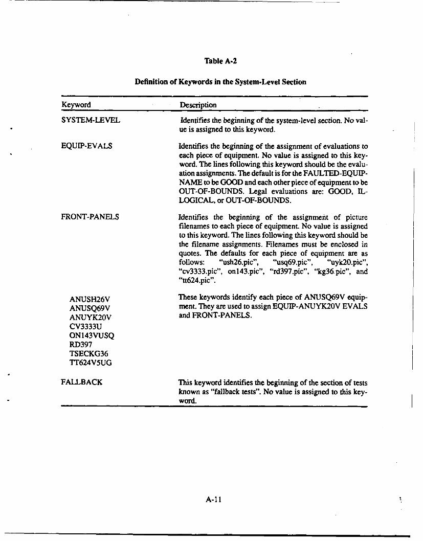
Table A-2
Definition of Keywords in the System-Level Section
Keyword Description
SYSTEM-LEVEL Identifies the beginning of the system-level section. No val-ue is assigned to this keyword.
EQUIP-EVALS Identifies the beginning of the assignment of evaluations toeach piece of equipment. No value is assigned to this key-word. The lines following this keyword should be the evalu-ation assignments. The default is for the FAULTED-EQUIP-NAME to be GOOD and each other piece of equipment to beOUT-OF-BOUNDS. Legal evaluations are: GOOD, IL-LOGICAL, or OUT-OF-BOUNDS.
FRONT-PANELS Identifies the beginning of the assignment of picturefilenames to each piece of equipment. No value is assignedto this keyword. The lines following this keyword should bethe filename assignments. Filenames must be enclosed inquotes. The defaults for each piece of equipment are asfollows: "ush26.pic", "usq69.pic", "uyk2O.pic',"cv3333.pic", onl43.pic", "rd397.pic", "kg36.pic", and"tt624.pic".
ANUSH26V These keywords identify each piece of ANUSQ69V equip-ANUSQ69V ment. They are used to assign EQUIP-ANUYK20V EVALSANUYK20V and FRONT-PANELS.CV3333UON143VUSQRD397TSECKG36FTT624V5UG
FALLBACK This keyword identifies the beginning of the section of testsknown as "fallback tests". No value is assigned to this key-word.
A-11
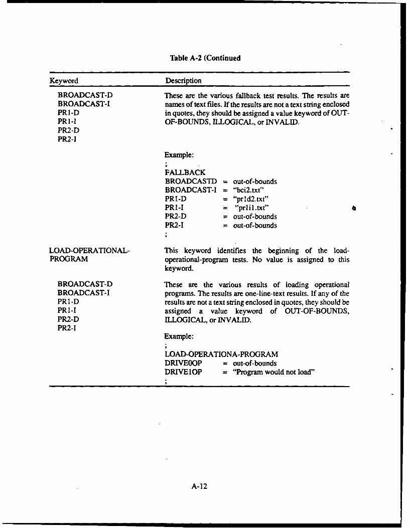
Table A-2 (Continued
Keyword Description
BROADCAST-D These are the various fallback test results. The results areBROADCAST-I names of text files. If the results are not a text string enclosedPR I-D in quotes, they should be assigned a value keyword of OUT-PR I-I OF-BOUNDS, ILLOGICAL, or INVALID.PR2-DPR2-1
Example:
FALLBACKBROADCASTD = out-of-boundsBROADCAST-I = "bci2.txt"PRI-D = "prld2.txt"PRI-I = "prlil.txt"PR2-D = out-of-boundsPR2-I = out-of-bounds
LOAD-OPERATIONAL- This keyword identifies the beginning of the load-PROGRAM operational-program tests. No value is assigned to this
keyword.
BROADCAST-D These are the various results of loading operationalBROADCAST-I programs. The results are one-line-text results. If any of thePR1-D results are not a text string enclosed in quotes, they should bePRI-I assigned a value keyword of OUT-OF-BOUNDS,PR2-D ILLOGICAL, or INVALID.PR2-I
Example:
LOAD-OPERATIONA-PROGRAMDRIVEOOP = out-of-boundsDRIVElOP = "Program would not load"
A-12
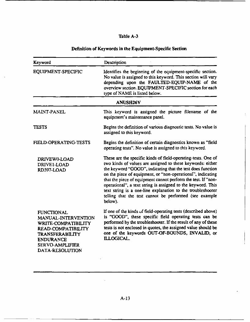
Table A-3
Definition of Keywords in the Equipment-Specific Section
Keyword Description
EQUIPMENT-SPECIFIC Identifies the beginning of the equipment-specific section.No value is assigned to this keyword. This section will varydepending upon the FAULTED-EQUIP-NAME of theoverview section. EQUIPMENT-SPECIFIC section for eachtype of NAME is listed below.
ANUSH26V
MAINT-PANEL This keyword is assigned the picture filename of theequipment's maintenance panel.
TESTS Begins the definition of various diagnostic tests. No value isassigned to this keyword.
FIELD-OPERATING-TESTS Begins the definition of certain diagnostics known as "fieldoperating tests". No value is assigned to this keyword.
DRIVEW0-LOAD These are the specific kinds of field-operating-tests. One ofDRIVEl-LOAD two kinds of values are assigned to these keywords: eitherRD397-LOAD the keyword "GOOD", indicating that the test does function
on the piece of equipment, or "non-operational", indicatingthat the piece of equipment cannot perform the test. If "non-operational", a text string is assigned to the keyword. Thistext string is a one-line explanation to the troubleshootertelling that the test cannot be performed (see examplebelow).
FUNCTIONAL If one of the kinds Lf field-operating tests (described above)MANUAL-INTERVENTION is "GOOD", these specific field operating tests can beWRITE-COMPATIBILITY performed by the troubleshooter. If the result of any of theseREAD-COMPATIBILITY tests is not enclosed in quotes, the assigned value should beTRANSFERABILITY one of the keywords OUT-OF-BOUNDS, INVALID, orENDURANCE ILLOGICAL.SERVO-AMPLIFIERDATA -RESOLUTION
A-13
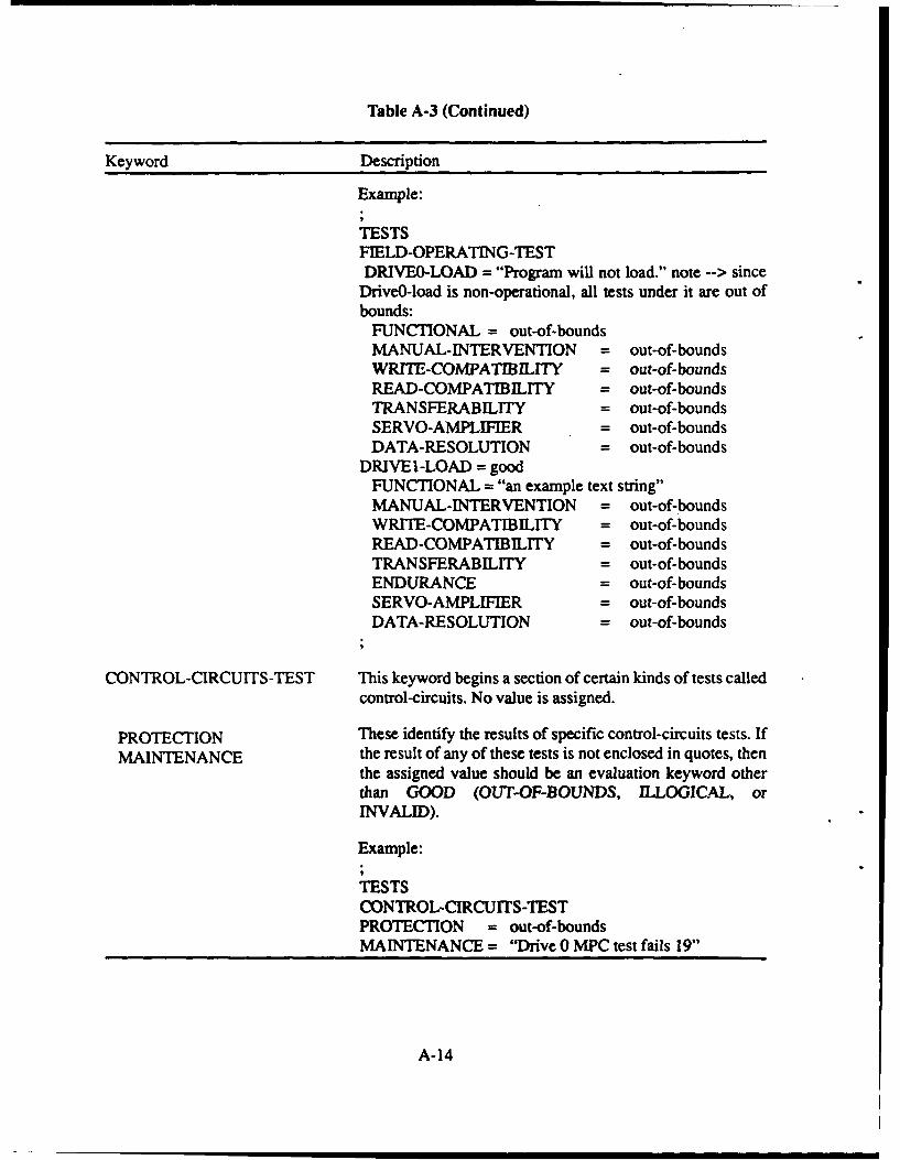
Table A-3 (Continued)
Keyword Description
Example:
TESTSFIELD-OPERATING-TESTDRIVEO-LOAD = "Program will not load." note --> since
Drive0-load is non-operational, all tests under it are out ofbounds:
FUNCTIONAL = out-of-boundsMANUAL-INTERVENTION = out-of-boundsWRITE-COMPATIBIL/TY = out-of-boundsREAD-COMPATIBILITY = out-of-boundsTRANSFERABILITY = out-of-boundsSERVO-AMPLIFIER = out-of-boundsDATA-RESOLUTION = out-of-bounds
DRIVE 1-LOAD = goodFUNCTIONAL = "an example text string"MANUAL-INTERVENTION = out-of-boundsWRITE-COMPATIBILrTY = out-of-boundsREAD-COMPATIBILITY = out-of-boundsTRANSFERABILITY = out-of-boundsENDURANCE = out-of-boundsSERVO-AMPLIFIER = out-of-boundsDATA-RESOLUTION = out-of-bounds
CONTROL-CIRCUITS-TEST This keyword begins a section of certain kinds of tests calledcontrol-circuits. No value is assigned.
PROTECTION These identify the results of specific control-circuits tests. If
MAINTENANCE the result of any of these tests is not enclosed in quotes, thenthe assigned value should be an evaluation keyword otherthan GOOD (OUT-OF-BOUNDS, ILLOGICAL, orINVALID).
Example:
TESTSCONTROL-CIRCUITS-TESTPROTECTION = out-of-boundsMAINTENANCE = "Drive 0 MPC test fails 19"
A-14
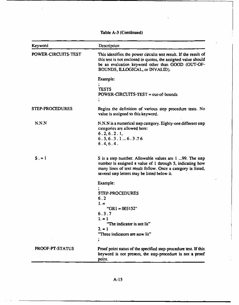
Table A-3 (Continued)
Keyword Description
POWER-CIRCUITS-TEST This identifies the power circuits test result. If the result ofthis test is not enclosed in quotes, the assigned value shouldbe an evaluation keyword other than GOOD (OUT-OF-BOUNDS, ILLOGICAL, or INVALID).
Example:
TESTSPOWER-CIRCUITS-TEST = out-of-bounds
STEP-PROCEDURES Begins the definition of various step procedure tests. Novalue is assigned to this keyword.
N.N.N N.N.N is a numerical step category. Eighty-one different stepcategories are allowed here:6.2,6.2.1,6.3,6.3.1 ... 6.3.766.4,6.4.
S. =1 S is a step number. Allowable values are 1 ...99. The stepnumber is assigned a value of 1 through 5, indicating howmany lines of text result follow. Once a category is listed,several step letters may be listed below it.
Example:
STEP-PROCEDURES6.21. =
"GRI = 003152"6.3.71.=I
"The indicator is not lit"2. = 1"Three indicators are now lit"
PROOF-PT-STATUS Proof point status of the specified step-procedure test. If thiskeyword is not present, the step-procedure is not a proofpoint.
A-15
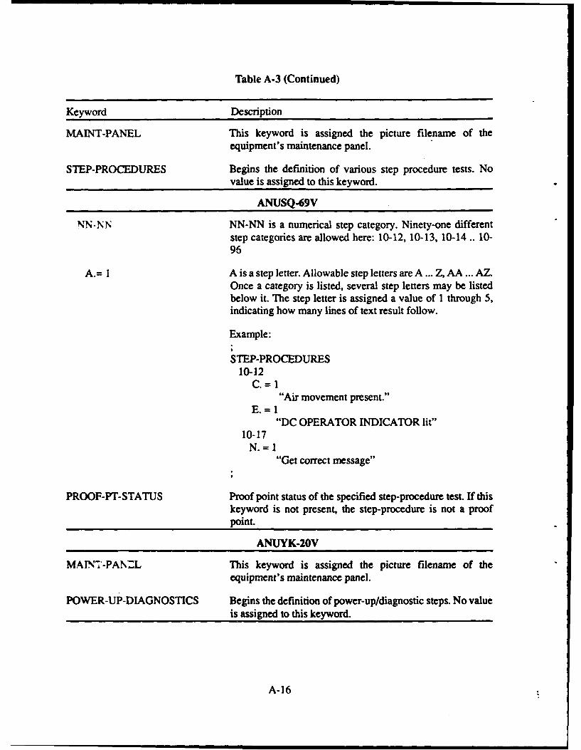
Table A-3 (Continued)
Keyword Description
MAINT-PANEL This keyword is assigned the picture filename of theequipment's maintenance panel.
STEP-PROCEDURES Begins the definition of various step procedure tests. No
value is assigned to this keyword.
ANUSQ-69V
NN- N NN-NN is a numerical step category. Ninety-one differentstep categories are allowed here: 10-12, 10-13, 10-14 .. 10-96
A.= I A is a step letter. Allowable step letters are A ... Z, AA ... AZ.Once a category is listed, several step letters may be listedbelow it. The step letter is assigned a value of 1 through 5,indicating how many lines of text result follow.
Example:
STEP-PROCEDURES10-12
C.-1"Air movement present."
E.=I"DC OPERATOR INDICATOR lit"
10-17N.=1
"Get correct message"
PROOF-PT-STATUS Proof point status of the specified step-procedure test. If thiskeyword is not present, the step-procedure is not a proofpoint.
ANUYK-20V
MAINT-PANML This keyword is assigned the picture filename of theequipment's maintenance panel.
POWER-UP-DIAGNOSTICS Begins the definition of power-up/diagnostic steps. No valueis assigned to this keyword.
A-16
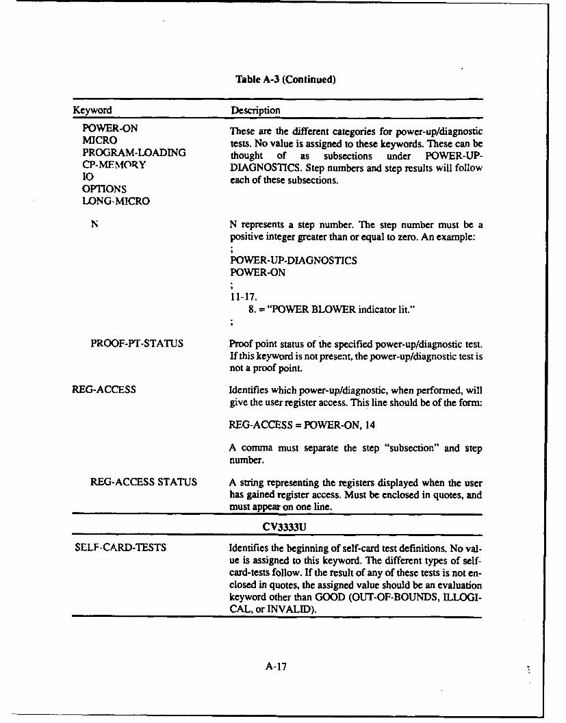
Table A-3 (Continued)
Keyword Description
POWER-ON These are the different categories for power-up/diagnosticMICRO tests. No value is assigned to these keywords. These can bePROGRAM-LOADING thought of as subsections under POWER-UP-CP-MFfMfORY DIAGNOSTICS. Step numbers and step results will follow10 each of these subsections.OPTIONSLONG-MICRO
N N represents a step number. The step number must be apositive integer greater than or equal to zero. An example:
POWER-UP-DIAGNOSTICSPOWER-ON
11-17.8. = "POWER BLOWER indicator lit."
PROOF-PT-STATUS Proof point status of the specified power-up/diagnostic test.If this keyword is not present, the power-up/diagnostic test isnot a proof point.
REG-ACCESS Identifies which power-up/diagnostic, when performed, willgive the user register access. This line should be of the form:
REG-ACCESS = POWER-ON, 14
A comma must separate the step "subsection" and stepnumber.
REG-ACCESS STATUS A string representing the registers displayed when the userhas gained register access. Must be enclosed in quotes, andmust appear on one line.
CV3333U
SELF-CARD-TESTS Identifies the beginning of self-card test definitions. No val-ue is assigned to this keyword. The different types of self-card-tests follow. If the result of any of these tests is not en-closed in quotes, the assigned value should be an evaluationkeyword other than GOOD (OUT-OF-BOUNDS, ILLOGI-CAL, or INVALID).
A-17
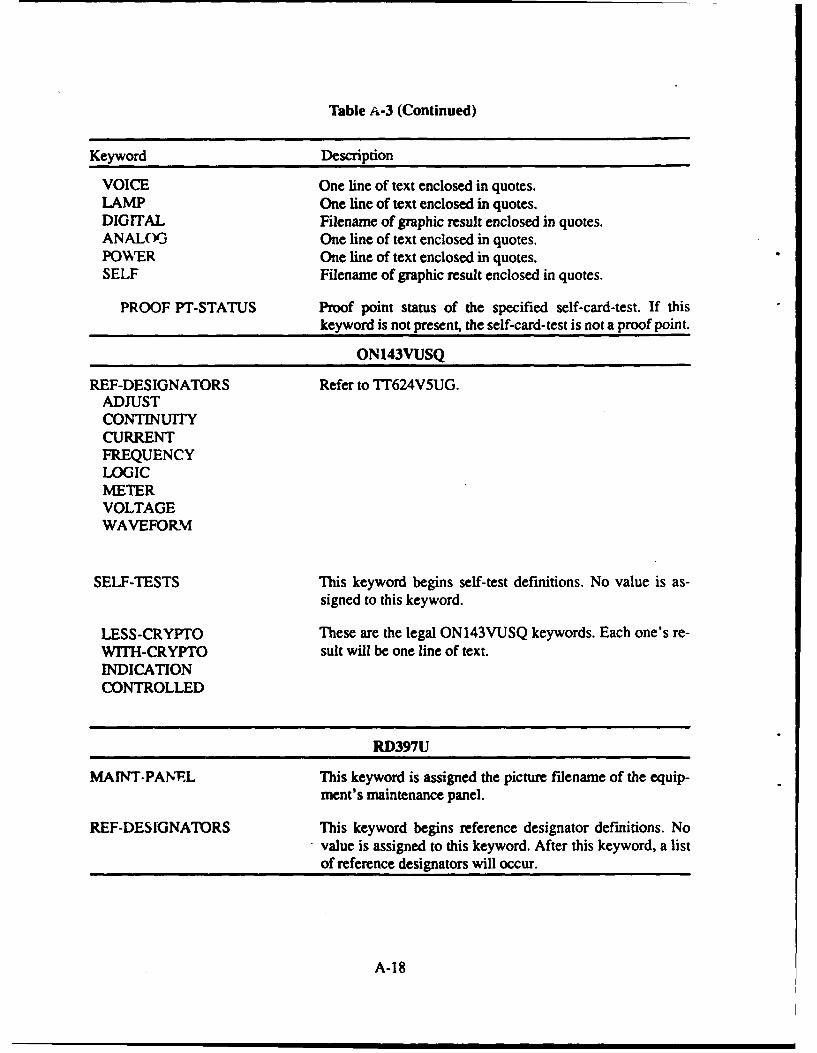
Table A-3 (Continued)
Keyword Description
VOICE One line of text enclosed in quotes.LAMP One line of text enclosed in quotes.DIGITAL Filename of graphic result enclosed in quotes.ANALOG One line of text enclosed in quotes.POWER One line of text enclosed in quotes.SELF Filename of graphic result enclosed in quotes.
PROOF PT-STATUS Proof point status of the specified self-card-test. If this
keyword is not present, the self-card-test is not a proof point.
ON143VUSQ
REF-DESIGNATORS Refer to TT624V5UG.ADJUSTCONTINUITYCURRENTFREQUENCYLOGICMETERVOLTAGEWAVEFORM
SELF-TESTS This keyword begins self-test definitions. No value is as-signed to this keyword.
LESS-CRYPTO These are the legal ON143VUSQ keywords. Each one's re-WITH-CRYPTO sult will be one line of text.INDICATIONCONTROLLED
RD397U
MAINT-PAN.L This keyword is assigned the picture filename of the equip-ment's maintenance panel.
REF-DESIGNATORS This keyword begins reference designator definitions. Novalue is assigned to this keyword. After this keyword, a listof reference designators will occur.
A-18
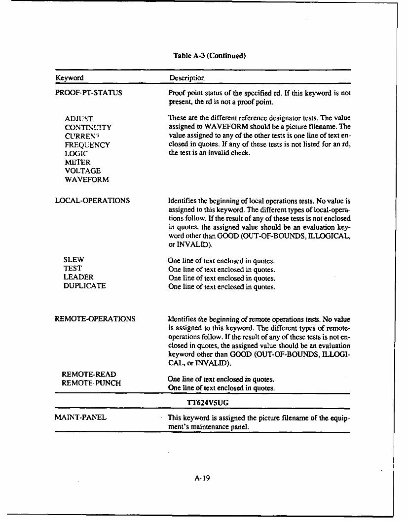
Table A-3 (Continued)
Keyword Description
PROOF-PT-STATUS Proof point status of the specified rd. If this keyword is notpresent, the rd is not a proof point.
ADJUST These are the different reference designator tests. The valueCONTINUITY assigned to WAVEFORM should be a picture filename. TheCURREN-) value assigned to any of the other tests is one line of text en-FREQUENCY closed in quotes. If any of these tests is not listed for an rd,LOGIC the test is an invalid check.METERVOLTAGEWAVEFORM
LOCAL-OPERATIONS Identifies the beginning of local operations tests. No value isassigned to this keyword. The different types of local-opera-tions follow. If the result of any of these tests is not enclosedin quotes, the assigned value should be an evaluation key-word other than GOOD (OUT-OF-BOUNDS, ILLOGICAL,or INVALID).
SLEW One line of text enclosed in quotes.TEST One line of text enclosed in quotes.LEADER One line of text enclosed in quotes.DUPLICATE One line of text epclosed in quotes.
REMOTE-OPERATIONS Identifies the beginning of remote operations tests. No valueis assigned to this keyword. The different types of remote-operations follow. If the result of any of these tests is not en-closed in quotes, the assigned value should be an evaluationkeyword other than GOOD (OUT-OF-BOUNDS, ILLOGI-CAL, or INVALID).
REMOTE-READ One line of text enclosed in quotes.REMOTE-P One line of text enclosed in quotes.
TT624VSUG
MAINT-PANEL This keyword is assigned the picture filename of the equip-ment's maintenance panel.
A-19
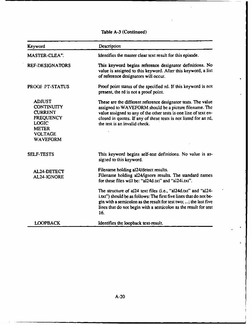
Table A-3 (Continued)
Keyword Description
MASTER-CLEA" Identifies the master clear text result for this episode.
REF-DESIGNATORS This keyword begins reference designator definitions. Novalue is assigned to this keyword. After this keyword, a listof reference designators will occur.
PROOF-PT-STATUS Proof point status of the specified rd. If this keyword is notpresent, the rd is not a proof point.
ADJUST These are the different reference designator tests. The valueCONTINUITY assigned to WAVEFORM should be a picture filename. TheCURRENT value assigned to any of the other tests is one line of text en-FREQUENCY closed in quotes. If any of these tests is not listed for an rd,LOGIC the test is an invalid check.METERVOLTAGEWAVEFORM
SELF-TESTS This keyword begins self-test definitions. No value is as-signed to this keyword.
AL24-DETECT Filename holding al24/detect results.
AL24-IGNORE Filename holding a124/ignore results. The standard namesfor these files will be: "a124d.txt" and "a124i.txt".
The structure of a124 text files (i.e., "al24d.txt" and "a24-i.txt") should be as follows: The first five lines that do not be-gin with a semicolon as the result for test two; ...; the last fivelines that do not begin with a semicolon as the result for test16.
LOOPBACK Identifies the loopback text-result.
A-20

EPISODE PRESENTATION REQUIREMENTS
Overview
This section describes the functional requirements of the NAVMACS TAE EpisodePresentation Program (PRESENT). The PRESENT program delivers troubleshooting episodes toNavy electronics students (troubleshooters) and collects their progress in a student historydatabase.
Each troubleshooting episode begins by showing the student the symptoms indicating howthe NAVMACS system is malfunctioning. At that point, the troubleshooter chooses simulated teststo perform on the system, and the PRESENT program displays the results that the real equipmentwould sho%. The troubleshooting session terminates when the troubleshooter isolates the systemfault and simulates replacement of the defective component.
During the presentation process, every meaningful action the troubleshooter makes is time-stamped and recorded in the student history database. The presentation timer begins when theepisode symptoms are displayed and terminates when the system fault is replaced. If thetroubleshooter tests a proof point, it is noted for credit at a later time in the evaluation stage.
The functional requirements of PRESENT fall into five groups:
I. User-Interaction Requirements - Requirements dictating the appearance and use of thePRESENT program.
2. Administrative Requirements - Functions which allow an instructor to set up specifictroubleshooting episodes for a student to run.
3. System Level Requirements - Simulated NAVMACS tests that are available for every pieceof equipment in the NAVMACS system.
4. Equipment Level Requirements - Simulated NAVMACS tests that are unique to each piece
of equipment in the NAVMACS system.
5. Miscellaneous Requirements - Requirements that do not fall into the above categories.
Each group is described in detail in the following subsections.
User-Interaction Requirements
The PRESENT program's menu hierarchy is illustrated in Figures A-5 and A-6. Figure A-5provides the PRESENT administrator menu and system level menu. Figure A-6 provides the menuhierarchy for the equipment specific tests.
A-21
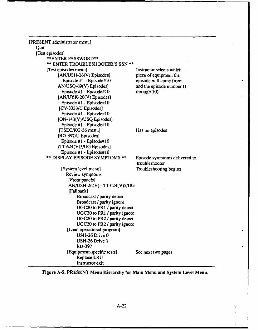
[PRESENT administrator menu]Quit[Test episodes]
**ENTER PASSWORD**** ENTER TROUBLESHOOTER'S SSN **
[Test episodes menu] Instructor selects which[AN/USH-26(V) Episodes] piece of equipment the
Episode #1 - Episode#10 episode will come from;ANIUSQ-69(V) Episodes] and the episode number (1
Episode #1 - Episode#10 through 10).[AN/JYK-20(V) Episodes]
Episode #1 - Episode#10[CV-3333/U Episodes]Episode #1 - Episode#10
[ON- 143(V)/USQ Episodes]Episode #1 - Episode#10
[TSEC/KG-36 menu] Has no episodes[RD-397/U Episodes]
Episode #1 - Episode#10[TI'-624(V)5/UG Episodes]
Episode #1 - Episode#10** DISPLAY EPISODE SYMPTOMS ** Episode symptoms delivered to
troubleshooter[System level menu] Troubleshooting begins
Review symptoms[Front panels]ANJUSH-26(V) - Tr-624(V)5/UG[Fallback]
Broadcast / parity detectBroadcast / parity ignoreUGC20 to PR I / parity detectUGC20 to PR I / parity ignoreUGC20 to PR2 / parity detectUGC20 to PR2 / parity ignore
[Load operational program]USH-26 Drive 0USH-26 Drive 1RD-397
[Equipment-specific tests] See next two pagesReplace LRUInstructor exit
Figure A-5. PRESENT Menu Hierarchy for Main Menu and System Level Menu.
A-22
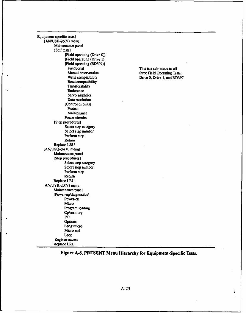
Equipment-specific tests][AN/USH-26(V) menu]
Maintenance panel[Self tests]
[Field operating (Drive 0)][Field operating (Drive 1)][Field operating (RD397)]
Functional This is a sub-menu to allManual intervention three Field Operating Tests:Write compatibility Drive 0, Drive 1, and RD397Read compatibilityTransferabilityEnduranceServo amplifierData resolution
[Control circuits]ProtectMaintenance
Power circuits[Step procedures]
Select step categorySelect step numberPerform stepReturn
Replace LRU[AN/USQ-69(V) menu]
Maintenance panel[Step procedures]
Select step categorySelect step numberPerform stepReturn
Replace LRU[AN/UYK-20(V) menu]
Maintenance panel[Power-up/diagnostics]
Power-onMicroProgram loadingCp/memoryI/OOptionsLong microMicro endLoop
Register accessReplace LRU
Figure A-6. PRESENT Menu Hierarchy for Equipment-Specific Tests.
A-23
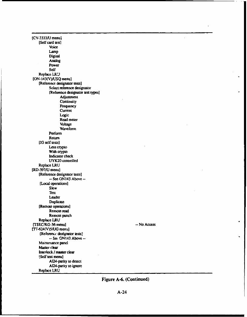
[CV-3333111 menu][Self card test]
VoiceLampDigitalAnalogPowerSelf
Replace LJKU[ON.143(V)/UTSQ menu]
[Reference designator tests)Select reference designator(Reference designator test types]
AdjustmentContinuityFrequencyCurrentLogicRead meterVoltageWaveform
PerformReturn
10 self tests]Less cryptoWith cryptoIndicator checkUYK20 controlled
Replace LRU[RD-397/U menu]
[Reference designator tests]-- See 0N143 Above-
[Local operations]SlewTestLeaderDuplicate
[Remote operations]Remote readRemote punch
Replace LRU[TSEC/KG-36 menu] -No Access1Th624(V)5#UG menu]
(Referencw designator tests]-Set 0N143 Above -
Maintenance panelMaster ClearInterlock / nmter clear[Self test menu]
A124-parity to detectA124-parity to ignore
Replace LRU
Figure A-6. (Continued)
A-24
Administrative Requirements
1. PRESENT begins with a display of the main menu. Figure A-5 displays the options on themain (administrator) menu. The Quit option returns the user to the operating system.
2. When the Test Episodes option is selected from the main menu, the user (instructor) will beasked to enter a password. An incorrect password will cause the program to return to the mainmenu.
3. If the password is entered correctly, the instructor will be prompted for a student's socialsecurity number. After the social security number has been entered, the instructor will beallowed to select the episode to be presented. Using menus, the instructor will first selectwhich piece of equipment the episode will be drawn from and then will select the particularepisode to be presented.
4. If the episode selected has already been run and successfully solved by the student, theinstructor will be asked if the episode is to be re-run.
5. If the episode selected has already been started and the student either took an instructor exitor had the episode left open because of a computer failure, the instructor will be asked if theepisode is to be continued from where the student left off, or rerun from the beginning.
6. Each piece of equipment, except the TSEC/KG-36, will have 10 episodes. No episodes willbe developed for the TSEC/KG-36.
7. Once selected, the presentation software will load the episode from the episode database. Thetroubleshooting session begins by presenting the episode's symptoms to the troubleshooter.
8. Episode symptoms may be text from one to five lines long or full-page graphic images. If thesymptoms are given as text, they must be enclosed in a box that is centered on the screen.
9. After the troubleshooter reads the episode symptoms, PRESENT will display the SystemLevel Menu (described in the next subsection).
10. When a troubleshooting session ends, the instructor must be given the opportunity to keeptesting on the same student, or to begin testing on a different student, or to exit. This choicemust be protected by having to enter the password again so that students cannot set up thenext episode without an instructor.
11. Choosing to test on the same student will eliminate the need to reenter that student's socialsecurity number. The instructor will go right into the episode selection menus.
12. Choosing to test on a new student will cause the program to ask for a new social securitynumber before going straight to the episode selection menus.
System Level Requirements
1. Figure A-5 displays the options on the System Level Menu. The Review Symptoms optionredisplays the episode's symptoms on the screen. After the troubleshooter reviews thesymptoms, they will be cleared from the screen.
A-25
2. The Front Panels option allows the troubleshooter to view the front panel of any of the eightpieces of equipment. Front panels will be simulated by Dr. Halo graphic images. Front panelsmay be out of bounds for an episode. (Note: Dr. Halo is a registered trademark of MediaCybernetics, Inc.)
3. The Fallback option allows the troubleshooter to perform one of six "fallback" tests. Any ofthe six fallback tests may be out of bounds or illogical for an episode. When in bounds of theepisode, fallback test results are 23 lines long.
4. The Load Operational Program option allows the troubleshooter to perform one of three"Load Operational Program" tests. Any of the three load operational program tests may beout of bounds or illogical for an episode. When in bounds of the episode, a load operationalprogram test result is one line long.
5. The Equipment-Specific option allows the troubleshooter to do more testing on a particularpiece of equipment, if the equipment is in bounds of the episode. A piece of equipment maybe out of bounds or illogical for an episode in which case the troubleshooter will not beallowed to perform tests on that piece of equipment. The next subsection provides moreinformation on the types of tests provided for each piece of equipment.
6. The Replace LRU option allows the troubleshooter to replace a "lowest replaceable unit" ina piece of equipment. Replaceable units are identified by reference designators. When thetroubleshooter selects this option, he must specify the reference designator of the component(unit) to be replaced and the piece of equipment the component resides in. If thetroubleshooter does not specify the LRU to be replaced before choosing "PerformReplacement" at the menu, no replacement shall be simulated, and no event shall be recordedin the student history. The program should alert the troubleshooter that the LRU is notdefined. If the replaced component is the episode's faulted component, the presentationprogram will inform the troubleshooter of his success and will return to the "Enter Password"form. If the replacement does not alleviate the fault, troubleshooting will continue.
7. The Instructor Exit option allows the instructor to terminate episode presentation. After thisoption is selected, the instructor must enter a password and a short reason for the termination.
Equipment Level Requirements
I1. The Replace LRU option (described in the previous subsection) should be accessible fromany of the pieces of equipment. Figure A-6 provides the menu options for the equipment-specific tests.
2. The Maintenance Panel option is available on the AN/IJSH-26(V), AN/USQ-69(V), AN/UYK-20(V), and the IT-624(V)5/UG. This option allows the troubleshooter to view themaintenance panel of these pieces of equipment. Maintenance panels will be simulated withDr. Halo graphic images.
3. Reference designator tests are available on the ON- 143(V)/USQ, the RD-397/U, and the IT-624(V)5/UG. There are eight types of reference designator tests: adjustment, continuity,frequency, current, logic, read meter, voltage, and waveform. The reference designator test(RD Test) option allows the troubleshooter to perform one of the above identified tests on aspecific component in the ON-143(V)/USQ, RD-397/U or in the TT-624(V)5/UG. When the
A-26
troubleshooter performs an RD test, he must specify the type of test and the referencedesignator of the component. The following subsections describe the functional requirementsof each piece of equipment.
AN/USH-26(V)
1. The Step Procedures option allows the troubleshooter to perform "Step Procedures" on theAN/USH-26(V). When the troubleshooter selects this option, a submenu will be displayedwith thtse options: Select Step Category, Select Step Number, Perform Step, and Return.
2. The Sc!.:ct Step Category option allows the troubleshooter to select one of the following 81categories: 6.2, 6.2.1, 6.3, 6.3.1, 6.3.2, 6.3.3, ..., 6.3.76, 6.4, and 6.4.1. The troubleshooterenters te category through an interactive form.
3. The Select Step Number option allows the troubleshooter to select a step number in the range0 to 99. The troubleshooter enters the number through an interactive form.
4. After selecting a step category and number, the troubleshooter may perform a step procedure
with the Perform Step option.
5. Step procedures may be out of bounds or good for an episode.
6. When the troubleshooter performs an out of bounds step procedure, PRESENT must ring thebell and inform the troubleshooter that the step procedure is out of bounds.
7. When the troubleshooter performs a good step procedure, PRESENT will display the resultof that step procedure. The result of a AN/JSH-26(V) step procedure will be either one-to-five-lines of text or a graphic image.
8. The Diagnostics option will bring up a menu containing AN/LJSH-26(V) diagnostics: FieldOperating (Drive 0), Field Operating (Drive 1), Field Operating (RD-397), Control Circuits,and Power Circuits.
9. The three Field Operating Tests (FOT) can either be operational or not operational for anepisode.
10. When the troubleshooter selects a FOT that is not operational, PRESENT must display asingle-line message identifying why the FOT is not operational.
11. When the troubleshooter selects a FOT that is operational, PRESENT will display the FOTdiagnostics menu, containing the options Functional through Data Resolution. Thetroubieshooter can then perform a FOT diagnostic. FOT diagnostics may be either out-of-bounds or good.
12. When the FOT diagnostic test is out of bounds, PRESENT must ring the bell and display anout of bounds message.
13. When the FOT diagnostic test is good, the result is one line of text.
14. When the troubleshooter selects the Control Circuits diagnostics option, PRESENT shoulddisplay a menu with the options Protect and Maintenance. Both of these tests can either begood or out of bounds. When good, the result is a single line of text.
A-27
15. The Power Circuits test is a stand-alone diagnostic that can either be good or out of bounds.When good, the result is one line of text.
ANIUSQ-69(V)
1. The Step Procedures option allows the troubleshooter to perform "Step Procedures" on theAN/USQ-69(V). When the troubleshooter selects this option, a submenu will be displayedwith the options: Select Step Category, Select Step Letter, Perform Step, and Return.
2. The Select Step Category option allows the troubleshooter to select one of the following 84categories: 10-12, 10-13, 10-14, ..., 10-96. The troubleshooter enters the category through aninteractive form.
3. The Select Step Letter option allows the troubleshooter to select a step letter. Step letters forthe ANIUSQ-69(V) are identified by one or two alphabetical characters; the lettering adheresto the following sequence: A, B, C, ..., Z, AA, AB, AC, ..., AY, AZ. There are no doublecharacter values past AZ. The troubleshooter enters the letter(s) through an interactive form.
4. Some step procedure categories do not have "sub" step letters; just entering the category issufficient for performing the step procedure.
5. After selecting a step category and letter (optional), the troubleshooter may perform a step
procedure with the Perform Step option.
6. A step procedure is either out of bounds or good for an episode.
7. When the troubleshooter performs an out of bounds step procedure, PRESENT must ring thebell and inform the troubleshooter that the procedure is out of bounds.
8. When the troubleshooter performs a good step procedure, PRESENT will display the resultof that step procedure. The result of a AN/USQ-69(V) step procedure will be either a one-to-five-line text result or a graphic image.
ANIUYK.20(V)
1. The Power-Up/Diagnostics option allows the troubleshooter to perform "Step Procedures"on the AN/UYK-20(V). The troubleshooter will select the category of step procedure to beperformed (Power-On through Loop). The troubleshooter must then enter a positive integeridentifying the particular step procedure to be performed. At that time, the presentationsoftware will display the result of the step procedure. An AN/UYK-20(V) step procedureresult is one line of text.
2. The Register Access option allows the troubleshooter to view the AN/UYK-20(V) registers.To view these registers, the troubleshooter must have first gained "register access". Thetroubleshooter gains register access by performing a specified step procedure. The "registerdisplay" will be represented by one line of text.
CV.3333/U
1. The Self Card Test option allows the troubleshooter to perform CV-3333/U self card tests(Voice through Self). Any of the self card tests can be out of bounds for the episode. "Digital"
A-28
and "Self" self card test results, when in bounds of the episode, will be simulated with Dr.
Halo graphic images. All other types of self card test results will be one line of text.
ON-143(V)/USQ
1. The RD Test option allows the troubleshooter to perform RD tests as described above.
2. The ON-143(V)/USQ equipment will have two troubleshooting shortcut options forperforming RD tests. The student may choose "Red Card Tests" or "Black Card Tests", whichwill prevent the student from having to enter two common reference designator prefixes forthis equipment. The student will be asked to enter "Pin Numbers", which will be appendedto the red or black reference designator prefixes. When the student selects "Perform" for ared or black card pin test, the test will be simulated just as though the student selected"Reference Designator Test" and entered the whole reference designator via the keyboard.
3. The IG Self Test option allows the troubleshooter to perform ON-143(V)/USQ self tests(Less Crypto through UYK2O Controlled). Any of the self tests can be out of bounds for theepisode. All ON-143(V)/USQ self test results will be one line of text. If the replacedcomponent is the episode's faulted component, the presentation program will inform thetroubleshooter of his success and will return to the "Enter Password" form. If the replacementdoes not alleviate the fault, troubleshooting will continue.
RD-397/U
1. The RD Test option allows the troubleshooter to perform RD tests as described above.
2. The Local Operations option allows the troubleshooter to perform RD-397/U Localoperations (Slew through Duplicate). Local operation test results are one line of text.
3. The Remote Operations option allows the troubleshooter to perform RD-397/U Remoteoperations (Remote read and Remote punch). Remote operation test results are one line oftext.
TT-624(V)5/UG
1. The RD Test option allows the troubleshooter to perform RD tests as described above.
2. The Master Clear and Interlock/Master Clear options both produce a one-line text result
3. The Self Test option allows the troubleshooter to perform TlI-624(V)5AJG AL24 tests (withthe parity switch set to either Detect or Ignore). Both types of AL24 tests (Detect and Ignore)require the troubleshooter to enter an AL24 test number. This number must be between 1 and16. After the test number has been specified, the presentation software will display the AL24test result. An AL24 test result is five lines of text.
Miscellaneous Requirements
I. In general, every type of text result should be centered and enclosed in a box. Some textresults are eighty (80) characters wide and fill the entire width of the screen; these will not bedisplayed in a box. Typically these are simulations of printer results.
A-29
2. Fallback and TT-624(V)5/UG AL24 test results can contain heart, diamond, and "blackmark" characters. AN/USQ-69(V) step procedure results can contain "3 horizontal lines" and"lower right corner" characters. These characters will be represented by characters from theIBM and IBM extended character sets. The heart will be represented by character numberthree; the diamond will be represented by character number four; the "black mark" will berepresented by character number 178; the "3 horizontal lines" will be represented bycharacter number 240; and the "lower right corner" will be represented by character number217.
3. Since there are no keys on the IBM keyboard for these characters, the following mappingswill be used in the episode definition files: a vertical bar ('I', decimal 124) will map into aheart; a caret ('A', decimal 94) will map into a diamond; a backwards apostrophe ("', decimal96) will map into a "black mark"; an open brace ('(', decimal 123) will map into "3horizontal lines"; and a close brace (')', decimal 125) will map into "lower right corner".Hence, when displaying Fallback, TT-624(V)5/UG AL24 test results, or AN/USQ-69(V) stepresults, the presentation software must display a heart, diamond, "black mark", "3 horizontalline", or "lower right comer" every time it encounters a vertical bar, caret, backwardsapostrophe, open brace, or close brace, respectively.
4. The preceding requirement implies that Fallback, Tr-624(V)5/UG AL24 test results, andAN/USQ-69(V) step results may not contain vertical bars, caret, backwards apostrophes,open braces, or close braces.
5. Each episode has one fault; the troubleshooter's goal is to find that fault and replace it. If thetroubleshooter replaces a component that is not the fault, it is considered an incorrectsolution. During the evaluation portion of TAE, points are deducted from a troubleshooter'sscore for incorrect solutions. The presentation software must also provide "Good FaultReplacements". These are replacements that do not alleviate the fault, but will not deduct anypoints from the troubleshooter's score. There will be a maximum of 15 reference designatorsthat can be "Good Fault Replacements" per episode.
6. A troubleshooter may run an episode more than once, but PRESENT only has to keep astudent history for the latest session. To help instructors track which episodes have beencompleted, PRESENT must maintain an "Episodes Completed Record" for eachtroubleshooter. The Episodes Completed Record identifies which episodes a troubleshooterhas finished, which episodes the troubleshooter took an instructor exit on, and which episodesthe troubleshooter has not attempted. The Episodes Completed Record is provided duringepisode selection, as illustrated in Figure A-7.
7. If the instructor selects an episode that has already been presented, a message should beprinted warning the instructor that the old student history will be overwritten. At that point,the instructor must verify continuation.
8. A maximum of 255 events will be allowed per troubleshooting episode.
9. The PRESENT program must remain running when a user hits any of the usual MS-DOSkeyboard sequences that normally terminate program execution, namely, Control-C, Control-Alt-Delete, Control-S, or Control-Break.
A-30

AN/USH-26 (V) Episodes SOLVED I-EXIT
1. One DONE2. Two DONE3. Three DONE4. Four5. File DONE6. Six7. Seven DONE8. Eight9. Nine DONE10 Ten
Return
Select An Episode; Then Press ENTER.
Figure A-7. Episodes Completed Record.
10. Whenever the PRESENT program is expecting the user to enter an "arrow key", as duringmenu selection, the program must prevent the user from engaging the NumLock key on thekeyboard, since engaging the NumLock key prevents the user from using the arrow keys.
A-31
STUDENT HISTORY VIEWING REQUIREMENTS
Overview
This section describes the functional requirements of the NAVMACS TAE Student HistoryViewing Program (EDITVIEW). The EDITVIEW program must provide a variety of tools forviewing and manipulating the student histories recorded by the NAVMACS TAE PRESENTprogram. Navy instructors and NPRDC personnel will use the EDITVIEW program to monitor theprogress of Navy troubleshooters.
Troubleshooting actions are recorded during episode presentation and are stored as events ina student history database. Table A-4 lists the event types stored in the student history database.Each event i6 time-stamped; time resolution is kept to the minute. The first event in a studenthistory is a login event, time-stamped at zero hours and zero minutes. The last event in a studenthistory is a logout event.
The functional requirements of EDITVIEW fall into five groups:
1. User-Interaction Requirements - Requirements dictating the appearance and use of theEDIT VIEW program.
2. Single History Requirements - Functions that operate on a single student history.
3. Multiple History Requirements - Functions that operate on multiple histories.
4. Multiple Scoring Requirements - Functions that show all of the final scores for a specifiedstudent, class averages on each episode, class size and class average over all the episodes.
5. Management Requirements - Functions that help manage and organize student histories.
Each group of requirements is described in detail in the following subsections.
User-Interaction Requirements
The hierarchy for the EDITVIEW main menu is illustrated in Figure A-8. The administrativemenu shown at the bottom of Figure A-8 is a hidden option that allows the EDITVIEW operatorto perform a variety of functions that are protected by password. The administrative menu and itsoptions are described as part of the management requirements at the end of this section.
A-32
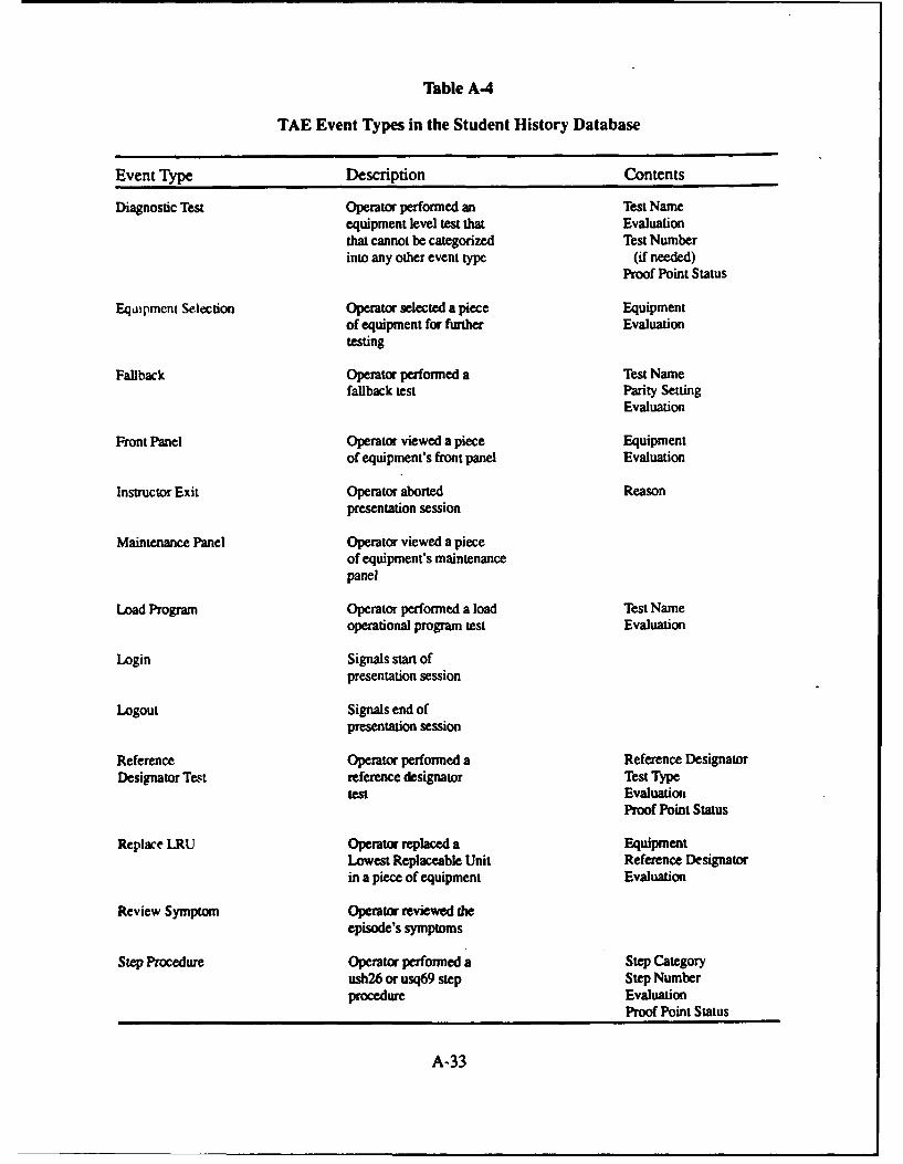
Table A.4
TAE Event Types in the Student History Database
Event Type Description Contents
Diagnostic Test Operator performed an Test Nameequipment level test that Evaluationthat cannot be categorized Test Numberinto any other event type (if needed)
Proof Point Status
Equipment Selection Operator selected a piece Equipmentof equipment for further Evaluationtesting
Fallback Operator performed a Test Namefallback test Parity Setting
Evaluation
Front Panel Operator viewed a piece Equipmentof equipment's front panel Evaluation
Instructor Exit Operator aborted Reasonpresentation session
Maintenance Panel Operator viewed a pieceof equipment's maintenancepanel
Load Program Operator performed a load Test Nameoperational program test Evaluation
Login Signals start ofpresentation session
Logout Signals end ofpresentation session
Reference Operator performed a Reference DesignatorDesignator Test reference designator Test Type
test EvaluationxProof Point Status
Replace LRU Operator replaced a EquipmentLowest Replaceable Unit Reference Designatorin a piece of equipment Evaluation
Review Symptom Operator reviewed heepisode's symptoms
Step Procedure Operator performed a Step Categoryush26 or usq69 step Step Numberprocedure Evaluation
Proof Point Status
A-33
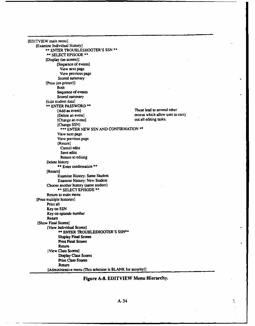
[EDITVIEW main menu][Examine Individual History]
** ENTER TROUBLESHOOTER'S SSN *** SELECT EPISODE **(Display (on screen)]
[Sequence of events]View next pageView previous page
Scored summary[Prilft (on printer)]
BothSequence of eventsScored summary
[Edit student data]** ENTER PASSWORD **
(Add an event] These lead to several other
[Delete an event] menus which allow user to carry[Change an event] out all editing tasks.[Change SSN]
*** ENTER NEW SSN AND CONFIRMATION **View next pageView previous page(Return]
Cancel editsSave editsReturn to editing
Delete history** Enter confirmation **
[Return]Examine History: Same StudentExamine History: New Student
Choose another history (same student)** SELECT EPISODE *
Return to main menu[Print multiple histories]
Print allKey on SSNKey on episode numberReturn
[Show Final Scores](View Individual Scores]
** ENTER TROUBLESHOOTER'S SSN**Display Final ScoresPrint Final ScoresReturn
[View Class Scores]Display Class ScoresPrint Class ScoresReturn
[Administrative menu (This selection is BLANK for security)]
Figure A-S. EDITVIEW Menu Hierarchy.
A-34
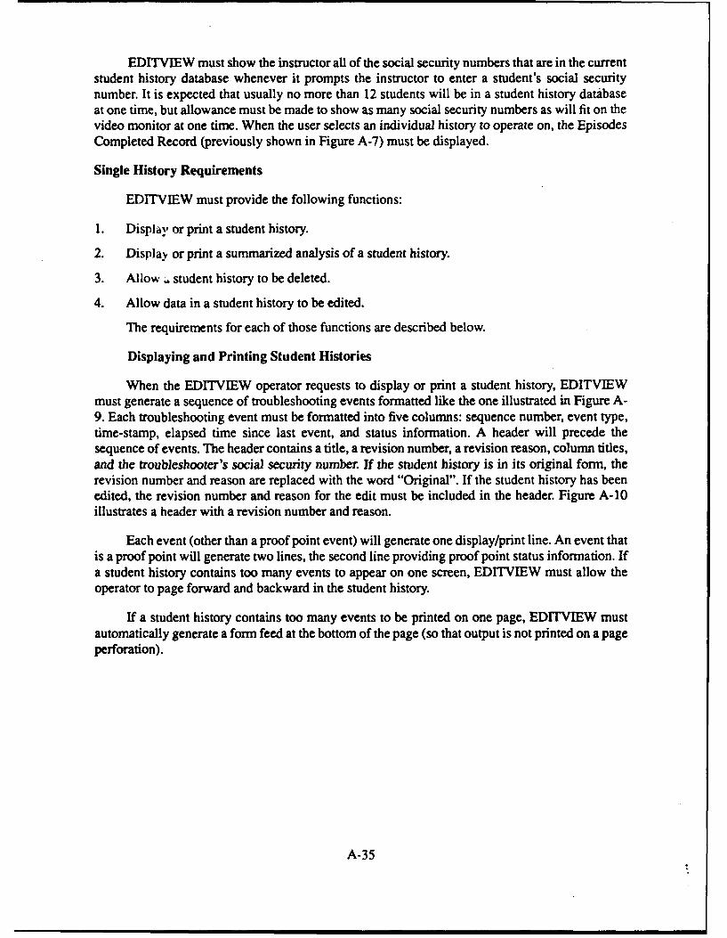
EDITVIEW must show the instructor all of the social security numbers that are in the currentstudent history database whenever it prompts the instructor to enter a student's social securitynumber. It is expected that usually no more than 12 students will be in a student history databaseat one time, but allowance must be made to show as many social security numbers as will fit on thevideo monitor at one time. When the user selects an individual history to operate on, the EpisodesCompleted Record (previously shown in Figure A-7) must be displayed.
Single History Requirements
EDITVIEW must provide the following functions:
1. Display or print a student history.
2. Display or print a summarized analysis of a student history.
3. Allow . student history to be deleted.
4. Allow data in a student history to be edited.
The requirements for each of those functions are described below.
Displaying and Printing Student Histories
When the EDITVIEW operator requests to display or print a student history, EDITVIEWmust generate a sequence of troubleshooting events formatted like the one illustrated in Figure A-9. Each troubleshooting event must be formatted into five columns: sequence number, event type,time-stamp, elapsed time since last event, and status information. A header will precede thesequence of events. The header contains a title, a revision number, a revision reason, column titles,and the troubleshooter's social security number. If the student history is in its original form, therevision number and reason are replaced with the word "Original". If the student history has beenedited, the revision number and reason for the edit must be included in the header. Figure A-10illustrates a header with a revision number and reason.
Each event (other than a proof point event) will generate one display/print line. An event thatis a proof point will generate two lines, the second line providing proof point status information. Ifa student history contains too many events to appear on one screen, EDITVIEW must allow theoperator to page forward and backward in the student history.
If a student history contains too many events to be printed on one page, ED1TVIEW mustautomatically generate a form feed at the bottom of the page (so that output is not printed on a pageperforation).
A-35
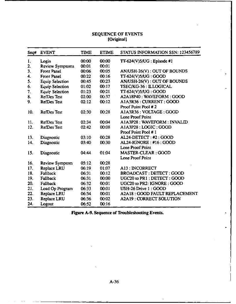
SEQUENCE OF EVENTS[Original]
Seq# EVENT TIME ETIME STATUS INFORMATION SSN: 123456789
1. Login 00:00 00:00 TI-624(V)5/UG: Episode #12. Review Symptoms 00:01 00:013. Front Panel 00:06 00:05 AN/USH-26(V): OUT OF BOUNDS4. Front Panel 00:22 00:16 T"-624(V)5/UG: GOOD5. Equip Selection 00:45 00:23 AN/USH-26(V): OUT OF BOUNDS6. Equip Selection 01:02 00:17 TSEC/KG-36: ILLOGICAL7. Equip. Selection 01:23 00:21 "rT-624(V)5/UG : GOOD8. Reftes Test 02:00 00:37 A2A18P40 : WAVEFORM : GOOD9. RefDes Test 02:12 00:12 A1A3R36 : CURRENT: GOOD
Proof Point Pool # 210. RefDes Test 02:30 00:28 A1A3R36 : VOLTAGE : GOOD
Lone Proof Point11. RefDes Test 02:34 00:04 A1A3P28 : WAVEFORM : INVALID12. RefDes Test 02:42 00:08 A1A3P28 : LOGIC : GOOD
Proof Point Pool # 113. Diagnostic 03:10 00:28 AL24-DETECT: #2 : GOOD14. Diagnostic 03:40 00:30 AL24-IGNORE : #16 : GOOD
Lone Proof Point15. Diagnostic 04:44 01:04 MASTER-CLEAR : GOOD
Lone Proof Point16. Review Symptom 05:12 00:2817. Replace LRU 06:19 01:07 A13 : INCORRECT18. Fallback 06:31 00:12 BROADCAST: DETECT : GOOD19. Fallback 06:31 00:00 UGC20 to PRI : DETECT: GOOD20. Fallback 06:32 00:01 UGC20 to PR2: IGNORE : GOOD21. Load Op Program 06:33 00:01 USH-26 Drive 1 : GOOD22. Replace LRU 06:34 00:01 A2A18 : GOOD FAULT REPLACEMENT23. Replace LRU 06:36 00:02 A2A19 : CORRECT SOLUTION24. Logout 06:52 00:16
Figure A-9. Sequence of Troubleshooting Events.
A-36
SEQUENCE OF EVENTS[Revision #1; Reason: Add step proc's, I-exit]
Seq# EVENT TIME ETIME STATUS INFORMATION SSN: 123456789
1. Login 00:00 00:00 AN/USH-26(V) : Episode #52. Review Symptoms 00:01 00:013. Front Panel 00:06 00:05 AN/USH-26(V): GOOD4. Front Panel 00:22 00:16 TT-624(V)5/UG: GOOD5. Load Op Program 00:22 00:00 RD397 Operation : GOOD6. Equir Selection 00:22 00:00 AN/USQ-69(V): OUT OF BOUNDS7. Equip Selection 00:23 00:00 AN/USH-26(V) : GOOD8. Maint Panel 00:23 00:009. Diagnostic 00:24 00:00 Fot Drive0: NOT OPERATIONAL10. Diagnostic 00:24 00:00 Fot Drivel : NOT OPERATIONAL11. Diagnostic 00:25 00:00 Fot RD397 : Functional : GOOD12. Diagnostic 00:27 00:01 Power Circuits : OUT OF BOUNDS13. Step Procedure 00:28 00:00 .,. : 1 : GOOD14. Step Procedure 00:28 00:00 6.3.7: 1: GOOD15. Step Procedure 00:29 00:00 6.3.7 : 2 : GOOD16. Step Procedure 00:29 00:00 6.3.7: 3 : GOOD17. Step Procedure 00:30 00:00 6.3.7: 4: OUT OF BOUNDS18. Instructor Exit 00:33 00:02 It is lunch time.19. Logout 00:33 00:00
Figure A-10. Revised Sequence of Events.
Displaying and Printing a Summarized Analysis
When the operator requests to display or print a summarized analysis, EDITVIEW mustgenerate a scored analysis like the example provided in Figure A-11.
SCORING SUMMARY
Description Number (Data) Score
TOTAL POINTS: +410.00FOUND SOLUTION: YES - 0.00TEST POINTS: 6 - 6.00OUr OF BOUNDS: 6 - 18.00VALID CHECK 6 - 1.50INVALID CHECKS: 5 -10.00REDUND ALN r CHECKS: 2 -4.00ILLOGICAL APPROACH: 1 -2.00INCORRECT SOLUTIONS: 1 -10.00PROOF POINTS: 2 OF 5 -6.00TOTAL TIME: 16 MINUTESFINAL SCORE: 344.50
Figure A-I. Example of a Scored Analysis.
A-37
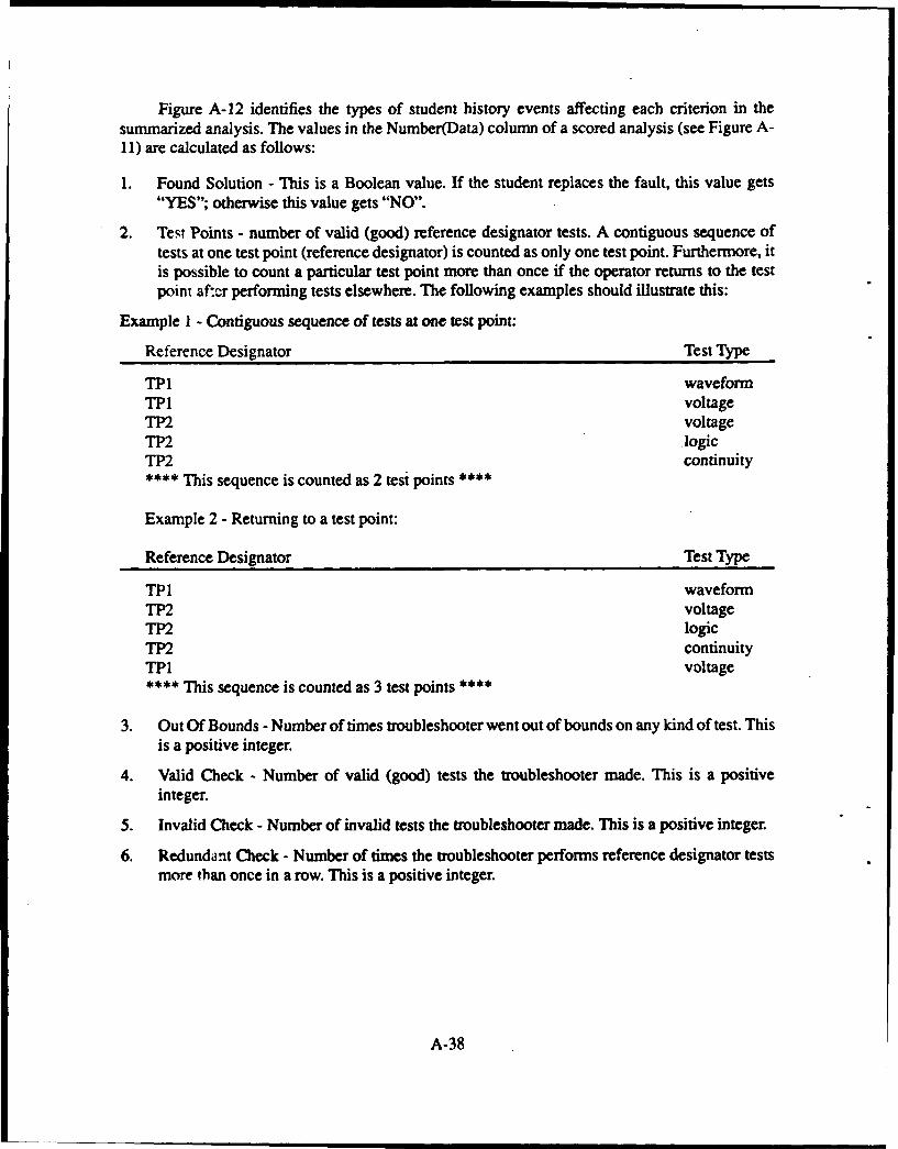
Figure A-12 identifies the types of student history events affecting each criterion in thesummarized analysis. The values in the Number(Data) column of a scored analysis (see Figure A-11) are calculated as follows:
1. Found Solution - This is a Boolean value. If the student replaces the fault, this value gets"YES"; otherwise this value gets "NO".
2. Test Points - number of valid (good) reference designator tests. A contiguous sequence oftests at one test point (reference designator) is counted as only one test point. Furthermore, itis possible to count a particular test point more than once if the operator returns to the testpoint af:r performing tests elsewhere. The following examples should illustrate this:
Example I - Contiguous sequence of tests at one test point:
Reference Designator Test Type
TP1 waveformTP1 voltageTP2 voltageTP2 logicTP2 continuity**** This sequence is counted as 2 test points *
Example 2 - Returning to a test point:
Reference Designator Test Type
TP1 waveformTP2 voltageTP2 logicTP2 continuityTP1 voltage**** This sequence is counted as 3 test points ****
3. Out Of Bounds - Number of times troubleshooter went out of bounds on any kind of test. Thisis a positive integer.
4. Valid Check - Number of valid (good) tests the troubleshooter made. This is a positiveinteger.
5. Invalid Check - Number of invalid tests the troubleshooter made. This is a positive integer.
6. Redundant Check - Number of times the troubleshooter performs reference designator testsmore than once in a row. This is a positive integer.
A-38
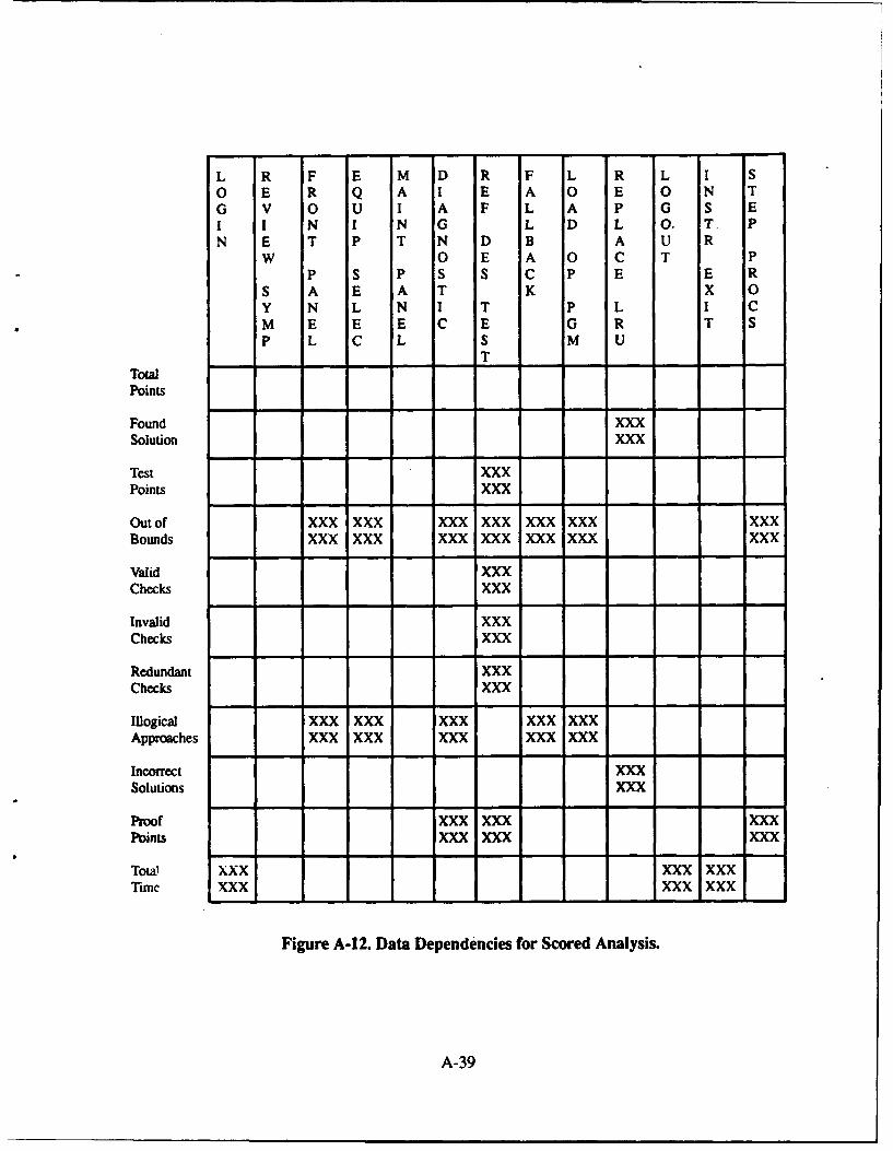
L R F E M D R F L R L I So E R Q A I E A 0 E 0 N TG V 0 U I A F L A P G S EI I N I N G L D L 0. T. PN E T P T N D B A U R
W 0 E A 0 C T PP S P S S C P E E R
S A E A T K X 0Y N L N I T P L I CM E E E C E G R T SP L C L S M U
T
TolPoints
Found XXXSolution XXX
Test XXXPoints XXX
Out of XXX XXX XXX XXX XXX XXX XXXBounds XXX XXX XXX XXX XXX XXX XXX
Valid XXXChecks XXX
Invalid XXXChecks XXX
Redundant XXXChecks XXX
Illogical XXX XXX XXX XXX XXXApproaches XXX XXX XXX XXX XXX
Incorrect XXXSolutions XXX
Proof XXX XXX XXXPoints XXX XXX XXX
Total XXX XXX XXXTime XXX XXX XXX
Figure A-12. Data Dependencies for Scored Analysis.
A-39
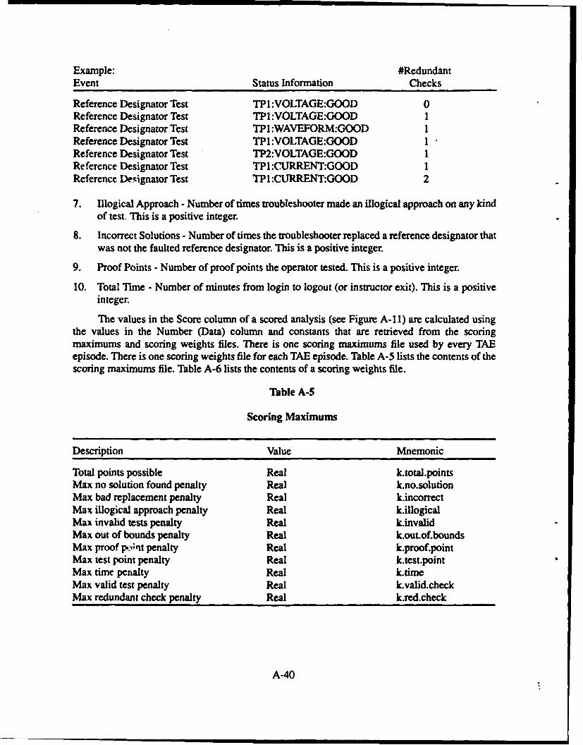
Example: #RedundantEvent Status Information Checks
Reference Designator Test TP1 :VOLTAGE:GOOD 0Reference Designator Test TPl:VOLTAGE:GOOD 1Reference Designator Test TPl :WAVEFORM:GOOD 1Reference Designator Test TP1:VOLTAGE:GOOD 1Reference Designator Test TP2:VOLTAGE:GOOD 1Reference Designator Test TP1 :CURRENT:GOOD 1Reference Designator Test TP1 :CURRENT:GOOD 2
7. Illogical Approach - Number of times troubleshooter made an illogical approach on any kindof test. This is a positive integer.
8. Incorrect Solutions - Number of times the troubleshooter replaced a reference designator thatwas not the faulted reference designator. This is a positive integer.
9. Proof Points - Number of proof points the operator tested. This is a positive integer.
10. Total Time - Number of minutes from login to logout (or instructor exit). This is a positiveinteger.
The values in the Score column of a scored analysis (see Figure A-I1) are calculated usingthe values in the Number (Data) column and constants that are retrieved from the scoringmaximums and scoring weights files. There is one scoring maximums file used by every TAEepisode. There is one scoring weights file for each TAE episode. Table A-5 lists the contents of thescoring maximums file. Table A-6 lists the contents of a scoring weights file.
Table A-5
Scoring Maximums
Description Value Mnemonic
Total points possible Real k.total.pointsMax no solution found penalty Real k.no.solutionMax bad replacement penalty Real k.incorrectMax illogical approach penalty Real k.illogicalMax invalid tests penalty Real k.invalidMax out of bounds penalty Real k.out.of.boundsMax proof p;nit penalty Real k.proof.pointMax test point penalty Real k.test.pointMax time penalty Real k.timeMax valid test penalty Real k.valid.checkMax redundant check penalty Real k.red.check
A-40
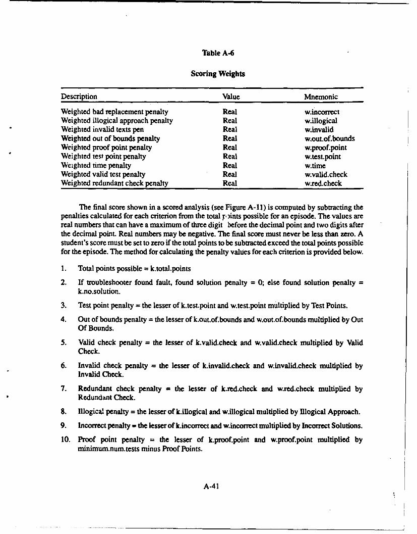
Table A-6
Scoring Weights
Description Value Mnemonic
Weighted bad replacement penalty Real w.incorrectWeighted illogical approach penalty Real w.illogicalWeighted invalid texts pen Real w.invalidWeighted out of bounds penalty Real w.out.of.boundsWeighted proof point penalty Real w.proof.pointWeighted test point penalty Real w.test.pointWeighted time penalty Real w.timeWeighted valid test penalty Real w.valid.checkWeighted redundant check penalty Real w.red.check
The final score shown in a scored analysis (see Figure A-11) is computed by subtracting thepenalties calculated for each criterion from the total p ,ints possible for an episode. The values arereal numbers that can have a maximum of three digit before the decimal point and two digits afterthe decimal point. Real numbers may be negative. The final score must never be less than zero. Astudent's score must be set to zero if the total points to be subtracted exceed the total points possiblefor the episode. The method for calculating the penalty values for each criterion is provided below.
1. Total points possible = k.total.points
2. If troubleshooter found fault, found solution penalty = 0; else found solution penalty =k.no.solution.
3. Test point penalty = the lesser of k.test.point and w.test.point multiplied by Test Points.
4. Out of bounds penalty = the lesser of k.out.of.bounds and w.out.of.bounds multiplied by OutOf Bounds.
5. Valid check penalty = the lesser of k.valid.check and w.valid.check multiplied by ValidCheck.
6. Invalid check penalty = the lesser of k.invalid.check and w.invalid.check multiplied byInvalid Check.
7. Redundant check penalty = the lesser of k.red.check and w.red.check multiplied byRedundant Check.
8. Illogical penalty = the lesser of k.illogical and w.illogical multiplied by Ilogical Approach.
9. Incorrect penalty = the lesser of k.incorrect and w.incorrect multiplied by Incorrect Solutions.
10. Proof point penalty = the lesser of k.proof.point and w.proof.point multiplied byminimum.num.tests minus Proof Points.
A-41
11. Time penalty = the lesser of k.time and w.time multiplied by Total Time.
Deleting a Student History
EDITVIEW must allow an instructor to remove a specific episode history for a given student.This action will permanently remove that history from the current student history database. Theinstructor must be given the opportunity to cancel this selection after choosing it.
Editing Data In a Student History
The editing facility must be menu-driven for compatibility with the rest of EDITVIEW andfor ease of u.w The ED1TVIEW operator must enter a password to receive access to event editing.After the correct password has been entered, the edit facility must display a sequence oftroubleshooting events similar to that provided by the display facility. The EDITVIEW operatormust then be allowed to:
1. Add an event to a student history.
2. Delete one or more events at a time from a student history.
3. Change an event in a student history.
4. Change the Social Security Number for the student history.
5. Page forward or backward in a student history.
6. Exit from event editing with the option to save the changes just made or abandon them.
A number of event editing rules are immediately apparent:
1. The operator should not be allowed to change or delete the first event (login) in a studenthistory.
2. The operator should not be allowed to change or delete the last event (logout) in a studenthistory.
3. If the history contains any revision events as a result of prior editing, it is illegal to change
the revision events.
4. The operator should not be allowed to add an event before the first event.
5. All other events must be fully editable. Any field in any event should be easily changeable.
When tme operator is finished making changes to a student history file, the EDITVIEWprogram must prompt the operator to enter a reason for making the edits. The reason will be typedin by the operator into an interactive form in the center of the monitor screen. The reason must belimited to 23 characters. This reason is then saved by the EDrTVIEW program as part of a"Revision Event", which is added to the student history after all other events. The next time thisstudent history is displayed or printed, the revision number and reason are displayed at the top, aspreviously shown in Figure A-10. Previous revision events are displayed at the bottom of the listof events, so that an instructor may view the editing history associated with the given student eventhistory.
A-42
Multiple History Requirements
EDITVIEW must provide a function that prints sets of student histories and summarizedanalyses at one time. The instructor must be able to specify these sets by episode or by socialsecurity number. The multiple printing function must allow the EDITVIEW operator to:
1. Print every student history and scored analysis with one command.
2. Print every student history for a single troubleshooter with one command.
3. Print every student history for a single episode with one command.
Multiple Scoring Requirements
EDITVIEW must provide a function that displays:
1. The set of final scores for each student in the student history database.
2. The number of students in the "class" (current student history database) and the overallaverage of all episodes completed by all students in the class.
Display Student Final Scores
Figure A-13 is an example of the final scores display for one student. The scores are alwayscalculated and shown for the specific set of 14 episodes shown in the figure. It is assumed that eachstudent will complete all of these episodes during the NAVMACS training course.
A-43
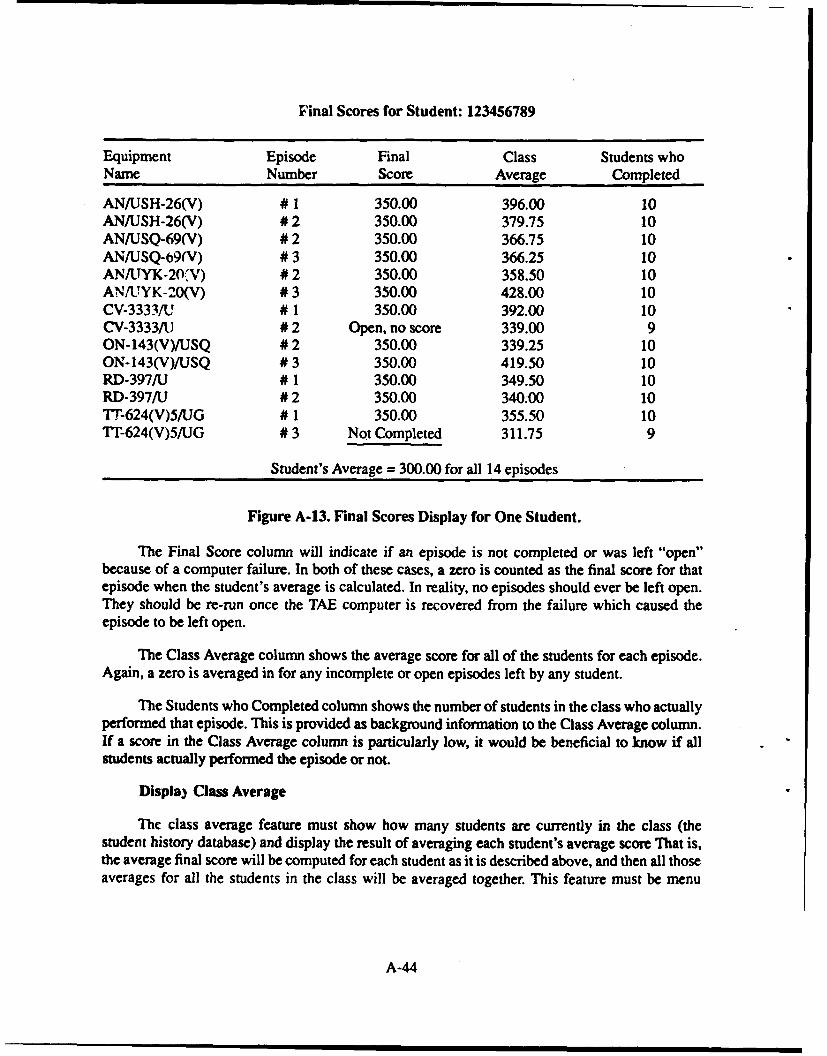
Final Scores for Student: 123456789
Equipment Episode Final Class Students whoName Number Score Average Completed
AN/USH-26(V) # 1 350.00 396.00 10AN/USH-26(V) # 2 350.00 379.75 10AN/USQ-69(V) # 2 350.00 366.75 10AN/USQ-69(V) # 3 350.00 366.25 10AN/AYK-20'V) # 2 350.00 358.50 10AN/UYK-20(V) # 3 350.00 428.00 10CV-33331U # 1 350.00 392.00 10CV-3333/U # 2 Open, no score 339.00 9ON-143(V)/USQ # 2 350.00 339.25 10ON-143(V)/USQ # 3 350.00 419.50 10RD-397/U # 1 350.00 349.50 10RD-397/J # 2 350.00 340.00 10T"-624(V)5/UG # 1 350.00 355.50 10TT-624(V)5/JG # 3 Not Completed 311.75 9
Student's Average = 300.00 for all 14 episodes
Figure A-13. Final Scores Display for One Student.
The Final Score column will indicate if an episode is not completed or was left "open"because of a computer failure. In both of these cases, a zero is counted as the final score for thatepisode when the student's average is calculated. In reality, no episodes should ever be left open.They should be re-run once the TAE computer is recovered from the failure which caused theepisode to be left open.
The Class Average column shows the average score for all of the students for each episode.Again, a zero is averaged in for any incomplete or open episodes left by any student.
The Students who Completed column shows the number of students in the class who actuallyperformed that episode. This is provided as background information to the Class Average column.If a score in the Class Average column is particularly low, it would be beneficial to know if allstudents actually performed the episode or not.
Displa) Class Average
The class average feature must show how many students are currently in the class (thestudent history database) and display the result of averaging each student's average score That is,the average final score will be computed for each student as it is described above, and then all thoseaverages for all the students in the class will be averaged together. This feature must be menu
A-44
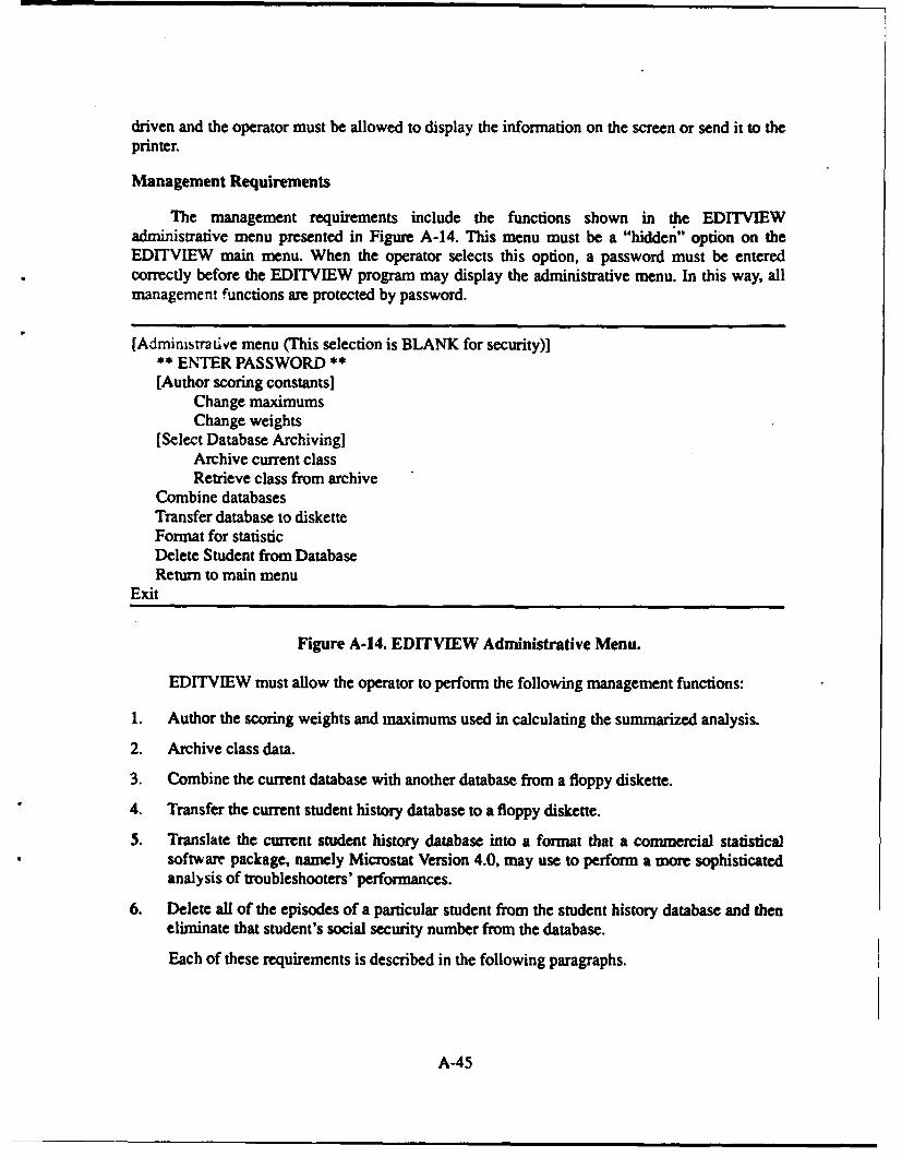
driven and the operator must be allowed to display the information on the screen or send it to the
printer.
Management Requirements
The management requirements include the functions shown in the EDITVIEWadministrative menu presented in Figure A-14. This menu must be a "hidden" option on theED1TVIEW main menu. When the operator selects this option, a password must be enteredcorrectly before the EDITVIEW program may display the administrative menu. In this way, allmanagement functions are protected by password.
[Administrative menu (This selection is BLANK for security)]** ENTER PASSWORD **[Author scoring constants]
Change maximumsChange weights
[Select Database Archiving]Archive current classRetrieve class from archive
Combine databasesTransfer database to disketteFormat for statisticDelete Student from DatabaseReturn to main menu
Exit
Figure A-14. EDITVIEW Administrative Menu.
EDITVIEW must allow the operator to perform the following management functions:
1. Author the scoring weights and maximums used in calculating the summarized analysis.
2. Archive class data.
3. Combine the current database with another database from a floppy diskette.
4. Transfer the current student history database to a floppy diskette.
5. Translate the current student history database into a format that a commercial statisticalsoftware package, namely Microstat Version 4.0, may use to perform a more sophisticatedanalysis of troubleshooters' performances.
6. Delete all of the episodes of a particular student from the student history database and theneliminate that student's social security number from the database.
Each of these requirements is described in the following paragraphs.
A-45
Authoring Scoring Constants
The function to author scoring constants must allow the EDITVIEW operator to:
1. Modify the scoring maximums file used for all episodes,
2. Create a scoring weights file for an episode.
3. Modify a scoring weights file for an episode.
The co'tents of these files were previously shown in Tables A-5 and A-6.
Archiving Student History Databases
The archive function must allow the EDITVIEW operator to:
1. Save the current student history database into an operator-named archive file area.
2. Retrieve an archived student history database by name from a list of all archived studenthistory databases.
The program will prompt the operator to name the archive with menus and interactive forms.The name of any student history database archive will consist of seven characters: a leading "S" ifthe class location is San Diego, California, or a leading "N" if the class location is Norfolk,Virginia, followed by six digits indicating the class date in the form MMDDYY
Figure A-15 illustrates the organization of student histories into the class archive.
A-46
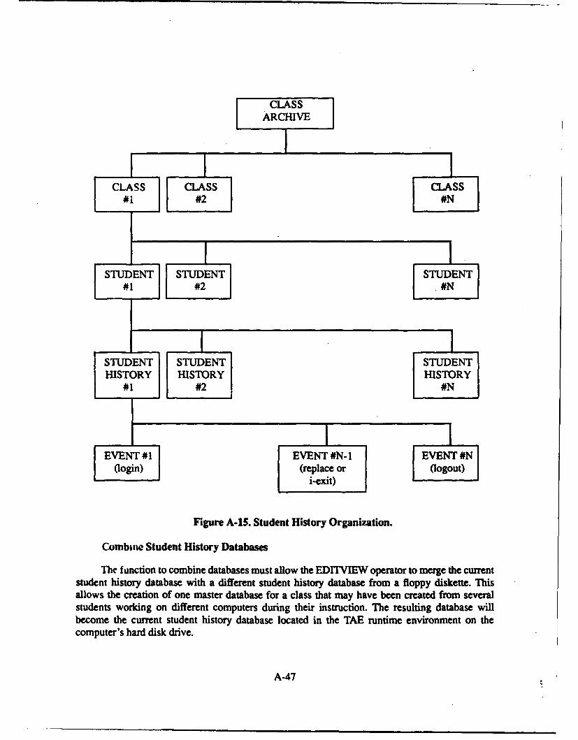
CLASSARCHIVE
CLASS CLASS LS1 #2
STUDENT STUDENT STUDENT#1 #2 #
STUDENT STUDENT STUDENTHISTORY HISTORY HISTORY
#1 #2 #N
EVENT #1 EVENT #N- 1 EVENT #N(login) (replace or (logout)
i-exit)
Figure A-15. Student History Organization.
Combine Student History Databases
The function to combine databases must allow the EDITVIEW operator to merge the currentstudent history database with a different student history database from a floppy diskette. Thisallows the creation of one master database for a class that may have been created from severalstudents working on different computers during their instruction. The resulting database willbecome the current student history database located in the TAE runtime environment on thecomputer's hard disk drive.
A-47
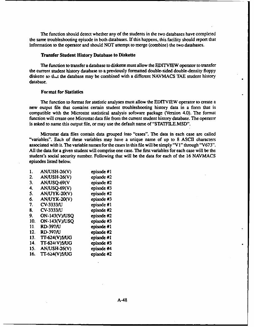
The function should detect whether any of the students in the two databases have completedthe same troubleshooting episode in both databases. If this happens, this facility should report thatinformation to the operator and should NOT attempt to merge (combine) the two databases.
Transfer Student History Database to Diskette
The function to transfer a database to diskette must allow the EDITVIEW operator to transferthe current student history database to a previously formatted double-sided double-density floppydiskette so th.t the database may be combined with a different NAVMACS TAE student historydatabase.
Format for Statistics
The function to format for statistic analyses must allow the EDITVIEW operator to create anew output file that contains certain student troubleshooting history data in a form that iscompatible with the Microstat statistical analysis software package (Version 4.0). The formatfunction will create one Microstat data file from the current student history database. The operatoris asked to name this output file, or may use the default name of "STATFILE.MSD".
Microstat data files contain data grouped into "cases". The data in each case are called"variables". Each of these variables may have a unique name of up to 8 ASCII charactersassociated with it. The variable names for the cases in this file will be simply "V I" through "V673".All the data for a given student will comprise one case. The first variables for each case will be thestudent's social security number. Following that will be the data for each of the 16 NAVMACSepisodes listed below.
1. ANIJSH-26(V) episode #12. AN/USH-26(V) episode #23. AN/USQ-69(V episode #24. AN/USQ-69(V) episode #35. ANAIYK-20(V) episode #26. AN/LYK-20(V) episode #37. CV-3333/U episode #18. CV-3333/U episode #29. ON-143(V)/USQ episode #210. ON-143(V)/JSQ episode #311 RD-397/U episode #112. RD-397/J episode #213. 7T-624(V)5/UG episode #114. TT-624(V)5/UG episode #315. AN/JSH-26(V) episode #416. TT-624(V)5/UG episode #2
A-48

The specific data for each episode and the order of output are listed below.
1. Equipment number (1=AN/USH-26(V) ... 8=TT-624(V)5/UG)2. Episode number3. Found Solution (1 = Yes, 0 = No)4. Number of Test Points5. Number of Out of Bounds tests6. Number of Valid Checks7. Number of Invalid Checks8. Number of Redundant Checks9. Number of Proof Points the subject tested10. Total number of Proof Points in the episode11. Percentage of Proof Points tested rounded to a whole number12. Total Time spent on the episode, in minutes13. Number of Illogical Approaches14. Number of Equipment Selection Events15. Number of Front Panel events16. Number of Maintenance Panel events17. Number of Fallback Test events18. Number of Reference Designator test events19. Number of Replace LRU events20. Number of Review Symptom events21. TBD (output a zero)22. Number of Diagnostic Test events23. Number of Load Operational Program events24. Number of Step Procedure events25. Number of Revision Events26. Number of Incorrect Replace LRU events27. Number of Good Fault Replacement Replace LRU events28. Tune until first Reference Designator Test, in minutes29. Time until first Diagnostic Test, in minutes30. Total number of steps taken in the episode: Includes Login and Logout, but not Revision
events31. Number of Waveform tests performed32. Number of Voltage tests performed33. Number of Read Meter tests performed34. Number of Logic tests performed35. Number of Curren: tests performed36. Number of Frequency tests performed37. Number of Continuity tests performed38. Number of Adjustment tests performed39. Final Score for the episode40. TBD (output a zero)41. TBD (output a zero)42. TBD (output a zero)
A-49
If a student has not completed a certain episode, the output file must contain the Microstatdesignation for "Missing" data in sufficient quantity to fill up the same number of output bytesnormally taken by the episode data.
Delete Student from Database
This function must allow the EDITVIEW operator to completely eliminate one particularstudent at a time from the current student history database. After the user enters the social securitynumber of the student to be deleted, the program must obtain a double confirmation from the userbefore actuaiiy deleting the student. All of the episodes that student performed, as well as thestudent's soci.d security number must be deleted from the database.
LOCAL AREA NETWORK REQUIREMENTS
The following requirements must be met:
1. The TAE system must function under a local area network (LAN) made by Corvus Systemsand known as Omninet. This particular commercial LAN product was selected by the Navyfor this project under a previous work order after evaluating several LANs available for IBMPC compatible computers.
2. The Navy schoolhouse which functions as the test facility for the TAE project has ten Zenith-248 computers in one classroom. One instructor supervises up to ten students at a time, andsets up each TAE troubleshooting episode individually for each student at each separatecomputer. The TAE system must be made to operate under the Omninet LAN so that theinstructor may work at one computer and set up troubleshooting episodes for the students atall of the remote computers. The various computers connected using a LAN are known as"nodes". The instructor's computer is referred to as the "administrator 'de" and thestudents' computers as the "student nodes".
3. The TAE system must continue to function normally if the administrator node fails. That is,if the instructor's computer experiences a hardware or software crash, the PRESENT andEDITVIEW programs must still run on the student nodes.
4. The PRESENT and EDITVIEW programs must run in their normal "stand-alone" MS-DOSenvironment as well as under the Omninet LAN environment.
5. The instructor must be able to access the student history databases on student nodes from theadministrator node.
A-50
APPENDIX B
TROUBLESHOOTING ASSESSMENT AND ENHANCEMENT (TAE)PROGRAM DESIGN DESCRIPTION
Page
IN T RO D C T IO N ............................................................................................................... B-I
TA F SY ST EM O V ERV IEW ............................................................................................... B-2
C ustom Softw are ............................................................................................................ B-2Episode A uthoring Program ................................................................................... B-2E pisode Presentation Program ............................................................................... B-2Student H istory View ing Program ......................................................................... B-4
Com m ercial Softw are U tilities ...................................................................................... B-4Form and M enu H andler ........................................................................................ B-4G raphics H andler .................................................................................................... B-5Database Handler .............................. B-5
TA E SY ST EM D ATA FLO W ............................................................................................. B-6
N AV M A C S SY ST EM M O D EL .......................................................................................... B-8
TA E H ardw are ............................................................................................................... B-8A bstract D ata D ictionary .............................................................................................. B-8
AD D EP PR O G R A M ............................................................................................................ B-13
Description ...................................................................................................................... B-13A D D EP A bstract D ata D ictionary .............................................................................. B-13Package D ependencies ................................................................................................... B-13
PRESENT PR O G R A M ..................................................................................................... B-15
Description ...................................................................................................................... B-15PR ESENT A bstract D ata D ictionary ......................................................................... B-15Package Dependencies ................................................................................................... B-20
EI)1'rVIE W PR O G R A M .................................................................................................... B-21
Description ...................................................................................................................... B-21ED ITV IEW A bstract Data D ictionary ........................................................................ B-21Package D ependencies ................................................................................................... B-22
B-0/i

TAE panel-pi CODE PACKAGE ....................................................................................... B-23
Description ..................................................................................................................... B-23TAE panel pl Code Package Abstract Data Dictionary ............................................ B-23PANEL Plus Conventions ............................................................................................ B-24
TAE GRAPHICS CODE PACKAGE ....... . ... .............. . ..... ....... B-27
TAE DATABASES AND THE TAE tpepdbs CODE PACKAGE ............... B-28
TAE Databases . ................. ... ... ......................... ... ......................... ...... . ..... ... ....... B-28
TAE tpepdbs Code Package Abstract Data Dictionary .......................................... B-33c-tree Conventions ......................................................................................................... B-37
TAE LOCAL AREA NETWORK DESIGN AND IMPLEMENTATION ................ B-38
LIST OF TABLES
B-I. NAVMACS Abstract Data Dictionary ................................................................... B-9B-2. ADDEP Abstract Data Dictionary ......................................................................... B-14B-3. PRESENT Abstract Data Dictionary .................................................................... B-16B-4. EDITVIEW Abstract Data Dictionary ................................................................. B-22B-5. TAE panel_pl Code Package Abstract Data Dictionary ..................................... B-24B-6. Episode Database Division ...................................................................................... B-32B-7. Student History Database Division ...................................................................... B-32B-. TAE tpepdbs Code Package Abstract Data Dictionary ..................................... B-34
LIST OF FIGURES
B-I. TAE System Context Diagram ............................................................................. B-3B-2. TAE Sstem Data Flow Diagram ........................................................................... B-6B-3. TAE System Utilities Data Flow Diagram ............................................................. B-7B-4. PRESENT Package Dependencies ........................................................................ B-20B-5. TAE panel pl Code Package Data Flow Diagram ....................... B-23B-6. TAE Graphics Code Package Data Flow Diagram ................... ....... B-27B-7. TAE Databases ....................................................................................... B-28B.8. Logical to Physical Mapping ........................... ....... B-29B-9. ANIUYK-20 (V) and TT-624 (V) S/UG Episodes . ........ B-30B-10. Database Layering............ ...... ............. B-31B-II. TAE tpepdbs Code Package Data Flow Diagram...... B-33
B-O/i
INTRC')UCTION
This appendix describes the Troubleshooting Assessment and Enhancement Program (TAE)system, designed for the Naval Modular Automated Communications Subsystem (NAVMACS).This document describes the entire TAE system with regard to its software design from theperspective of the software developer. It assumes that the TAE System Requirements Document(SRD) is available for reference (see Appendix A).
The appendix is organized into sections ordered in increasing levels of detail. The first sectionprovides an overview of the system, including a definition of the system context and a briefdescription of each of the system components. The next two sections present the system-level dataflow and the global abstract data dictionary. The remaining sections describe each of the systemcomponents in detail, including a data flow diagram, a data dictionary, and implementationconventions.
Some of the terms used throughout the documents are defined below:
Component--The lowest replaceable hardware unit.
Episode--A state of the system to be presented to the student. kn episode contains a single faultin a piece of equipment.
Equipment--A piece of hardware that performs a particular function. A piece of equipmentconsists of one or more components.
Picture--A Dr. Halo picture file to be displayed on the EGA graphics card (640 x 350 pixels, 16colors).
Proof Point--A test on a component which gives the troubleshooter a particular clue as to theource of the equipment's fault.
Reference designator--Label identifying a physical component in a piece of equipment.
System--A collection of two or more pieces of equipment.
B-1
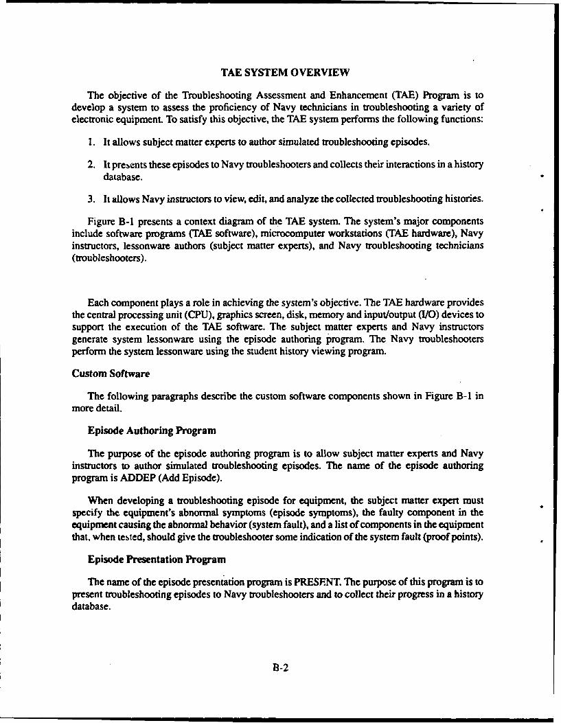
TAE SYSTEM OVERVIEW
The objective of the Troubleshooting Assessment and Enhancement (TAE) Program is todevelop a system to assess the proficiency of Navy technicians in troubleshooting a variety ofelectronic equipment. To satisfy this objective, the TAE system performs the following functions:
1. It allows subject matter experts to author simulated troubleshooting episodes.
2. It presents these episodes to Navy troubleshooters and collects their interactions in a historydatabase.
3. It allows Navy instructors to view, edit, and analyze the collected troubleshooting histories.
Figure B-1 presents a context diagram of the TAE system. The system's major componentsinclude software programs (TAE software), microcomputer workstations (TAE hardware), Navyinstructors, lessonware authors (subject matter experts), and Navy troubleshooting technicians(troubleshooters).
Each component plays a role in achieving the system's objective. The TAE hardware providesthe central processing unit (CPU), graphics screen, disk, memory and input/output (I/O) devices tosupport the execution of the TAE software. The subject matter experts and Navy instructorsgenerate system lessonware using the episode authoring program. The Navy troubleshootersperform the system lessonware using the student history viewing program.
Custom Software
The following paragraphs describe the custom software components shown in Figure B-I inmore detail.
Episode Authoring Program
The purpose of the episode authoring program is to allow subject matter experts and Navyinstructors to author simulated troubleshooting episodes. The name of the episode authoringprogram is ADDEP (Add Episode).
When developing a troubleshooting episode for equipment, the subject matter expert mustspecify the equipment's abnormal symptoms (episode symptoms), the faulty component in theequipment causing the abnormal behavior (system fault), and a list of components in the equipmentthat, when tested, should give the troubleshooter some indication of the system fault (proof points).
Episode Presentation Program
The name of the episode presentation program is PRESENT. The purpose of this program is topresent troubleshooting episodes to Navy troubleshooters and to collect their progress in a historydatabase.
B-2
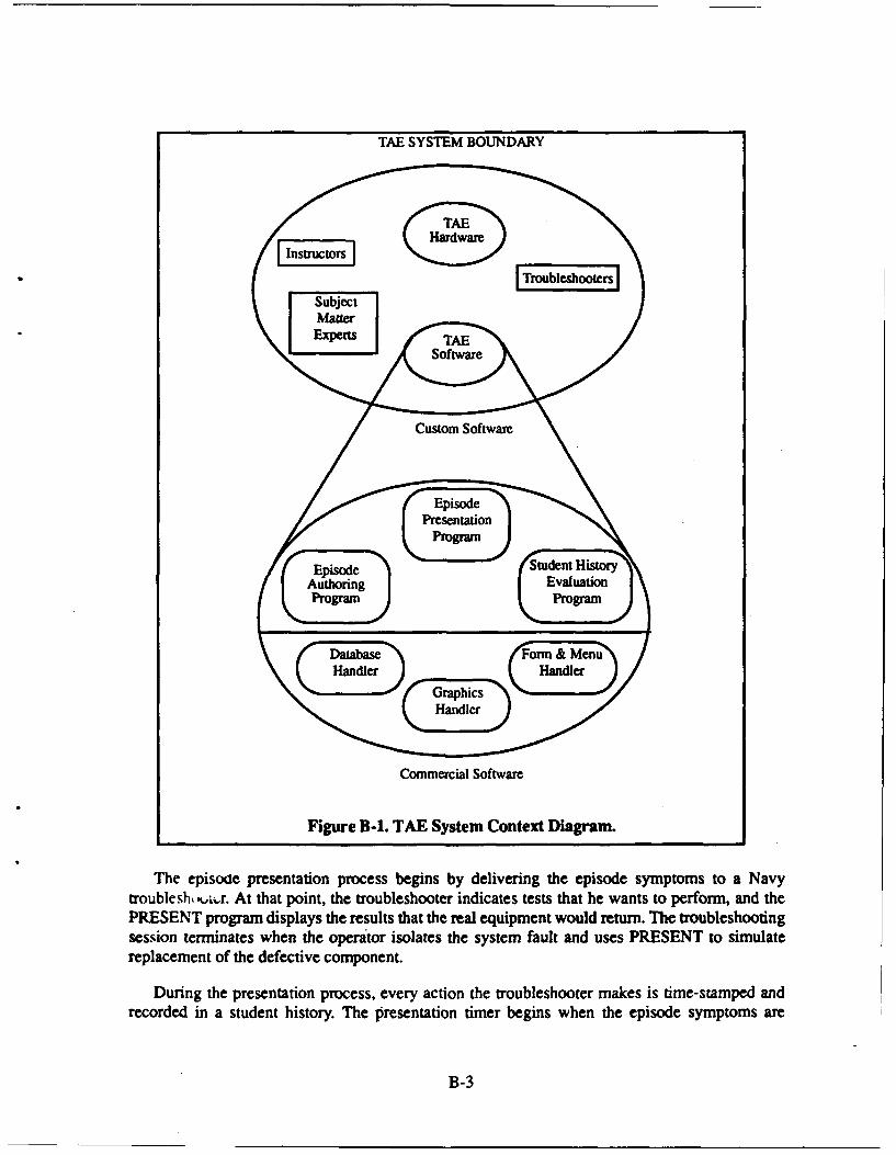
TAE SYSTEM BOUNDARY
_Subject
MatterExpertsTA
Custom Software
Episode
Presentation
Episode syAuthoring Evaluation
trouble sh, ,r At that point, the troubleshooter indicates tests that he wants to perform, and thePRESENT program displays the results that the real equipment would return. The troubleshooting
session terminates when the operator isolates the system fault and uses PRESENT to simulatereplacement of the defective component.
During the presentation process, every action the troubleshooter makes is time-stamped andrecorded in a student history. The presentation timer begins when the episode symptoms are
B-3
displayed and terminates when the system fault is replaced. If the troubleshooter tests a proof point,
it is noted for credit at a later time in the evaluation stage.
Student History Viewing Program
The name of the student history viewing program is EDITVIEW. The purpose of this programis to allow Navy instructors to view, edit, and analyze the troubleshooting histories collected by theepisode presentation program (PRESENT). Other database management functions are also builtinto the progrtm.
The "viev" function formats and displays each event in the student history in chronologicalorder. The information displayed for each event includes the time (relative to the start time) thatthe event occ.urred, the elapsed time since the last event, the event type, and status informationrelated to the event type. Student histories may also be printed on a printer connected to thecomputer on which EDITVIEW is running.
The "edit" function allows Navy instructors to edit (add, delete, or modify) events in a studenthistory.
The "analyze" function generates a report card summarizing the troubleshooter's performancein the episode. A specialized, statistical software package would be required to do a collectiveanalysis of all troubleshooters' performances.
The other database management functions allow Navy instructors to save (archival) andretrieve student history databases, combine two different student history databases into one largerdatabase, delete a student from the database, and translate the student data into a file that can beread by Microstat, a separate statistical analysis software package.
Commercial Software Utilities
The following paragraphs describe the commercial software components shown in Figure B-Iin more detail. Identification of specific equipment and software is for documentation only anddoes not imply endorsement.
Form and Menu Handler
The form and menu handler is a screen management utility used by PRESENT andEDITVIEW. Its purpose is to display TAE forms and menus. The TAE code package name of theform and menu handler is "paneLp".
The form and menu handler is implemented with the commercial software package PANELPlus, by Roundhill Computer Systems. PANEL Plus provides an interactive screen editor forcreating screen images such as forms and menus. If a cosmetic or syntactic change needs to bemade to a menu or form, it can be done in a matter of seconds with the panel editor.
PANEL Plus also provides 4 variety of screen management functions in the form of a linkablesoftware library. This library provides the means of displaying the menus and forms authored withthe panel editor.
B-4
Graphics Handler
The graphics handler is a graphics display utility used by the PRESENT program. Its primarypurpose is to display Dr. Halo full-screen graphics. Its secondary purpose is to provide a set ofroutines for drawing simple graphics. The TAE code package name of the graphics handler is"graphics".
The graphic drawing routines are implemented with the commercial software packageMetaWINDOW/PLUS, by Metagraphics Software Corporation. MetaWINDOW/PLUS provides awide variety of graphic drawing routines in the form of a linkable software library. Presently,MetaWINDOW/PLUS is used only to draw simple graphics over Dr. Halo images (for example, abox with some status information). (Note. Dr. Halo is a registered trademark of Media Cybernetics,Inc.) If future requirements dictate more advanced graphic capabilities, MetaWINDOW/PLUS iscapable of meeting them.
Database Handler
The purpose of the database handler is to provide access to the episode and student historydatabases. The database handler is used by ADDEP, PRESENT, and ED1TVIEW. The packagename of the database handler is "tpep_dbs'.
The database handler is implemented with the commercial software package c-tree (version4.1, release F), by FairCom.
B-5
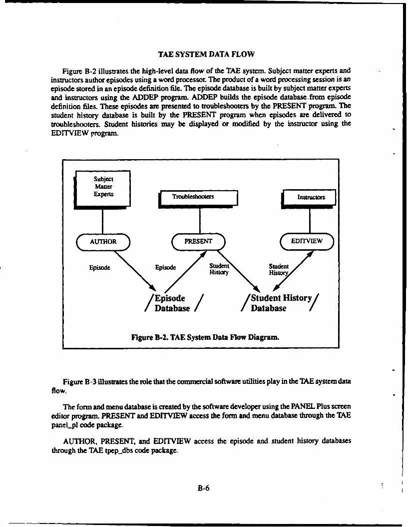
TAE SYSTEM DATA FLOW
Figure B-2 illustrates the high-level data flow of the TAE system. Subject matter experts andinstructors author episodes using a word processor. The product of a word processing session is anepisode stored in an episode definition file. The episode database is built by subject matter expertsand instructors using the ADDEP program. ADDEP builds the episode database.from episodedefinition files. These episodes are presented to troubleshooters by the PRESENT program. Thestudent history database is built by the PRESENT program when episodes are delivered totroubleshooters. Student histories may be displayed or modified by the instructor using theEDITVIEW program.
SubjectMauterExperts Troubleshooters Instructors
AUrHOR "XETEDITV]EW
Epide LSO uxentStudesnt
Episode e /Student History
Database /Database /
Figure B-2. TAE System Data Flow Diagram.
Figure B -3 illustrates the role that the commercial software utilities play in the TAE system dataflow.
The form and menu database is created by the software developer using the PANEL Plus screeneditor program. PRESENT and EDITVIEW access the form and menu database through the TAEpaneLpl code package.
AUTHOR, PRESENT, and EDITVIEW access the episode and student history databasesthrough the TAE tpep..dbs code package.
B-6
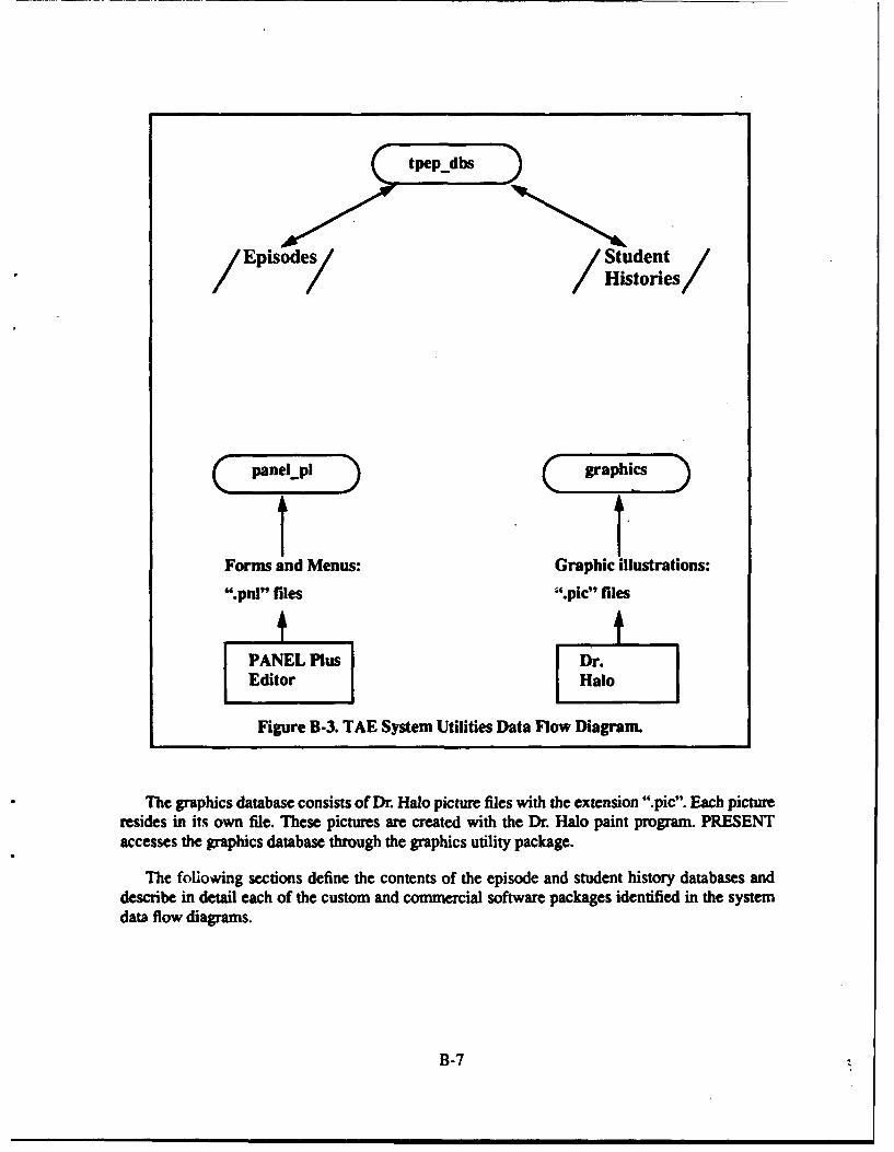
tpep_dbs
/ Episode / Students/
Forms and Menus: Graphic illustrations:
".pnl" files '.pic" files
Figure B-3. TAE System Utilities Data Flow Diagram.
The graphics database consists of Dr. Halo picture files with the extension ".pic". Each pictureresides in its own file. These pictures are created with the Dr. Halo paint program. PRESENTaccesses the graphics database through the graphics utility package.
The following sections define the contents of the episode and student history databases anddescribe in detail each of the custom and commercial software packages identified in the systemdata flow diagrams.
B-7
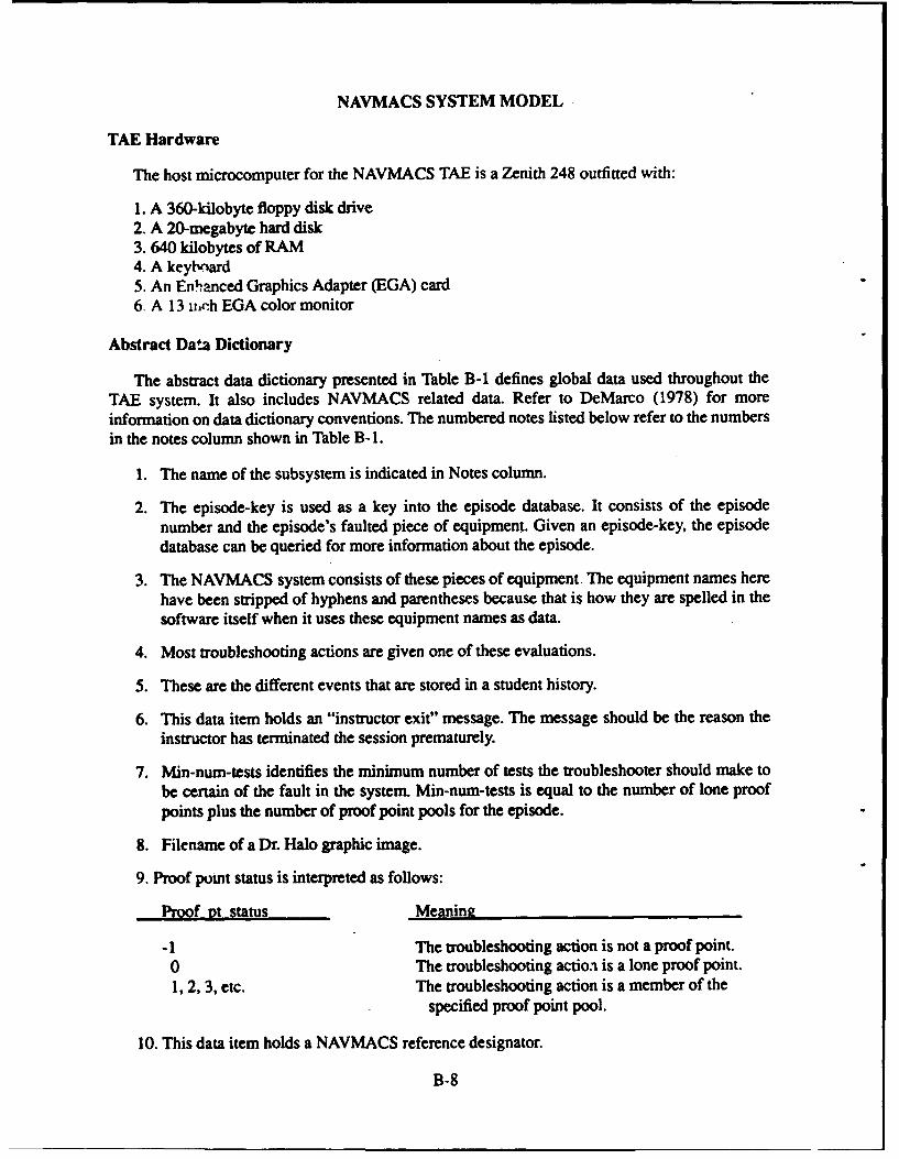
NAVMACS SYSTEM MODEL
TAE Hardware
The host microcomputer for the NAVMACS TAE is a Zenith 248 outfitted with:
1. A 360-kilobyte floppy disk drive2. A 20-megabyte hard disk3. 640 kilobytes of RAM4. A keyb, ard5. An En~nced Graphics Adapter (EGA) card6. A 13 iich EGA color monitor
Abstract Data Dictionary
The abstract data dictionary presented in Table B-1 defines global data used throughout theTAE system. It also includes NAVMACS related data. Refer to DeMarco (1978) for moreinformation on data dictionary conventions. The numbered notes listed below refer to the numbersin the notes column shown in Table B-1.
1. The name of the subsystem is indicated in Notes column.
2. The episode-key is used as a key into the episode database. It consists of the episodenumber and the episode's faulted piece of equipment. Given an episode-key, the episodedatabase can be queried for more information about the episode.
3. The NAVMACS system consists of these pieces of equipment. The equipment names herehave been stripped of hyphens and parentheses because that is how they are spelled in thesoftware itself when it uses these equipment names as data.
4. Most troubleshooting actions are given one of these evaluations.
5. These are the different events that are stored in a student history.
6. This data item holds an "instructor exit" message. The message should be the reason theinstructor has terminated the session prematurely.
7. Min-num-tests identifies the minimum number of tests the troubleshooter should make tobe certain of the fault in the system. Min-num-tests is equal to the number of lone proofpoints plus the number of proof point pools for the episode.
8. Filename of a Dr. Halo graphic image.
9. Proof point status is interpreted as follows:
Proof pt status Meaning
-1 The troubleshooting action is not a proof point.0 The troubleshooting action is a lone proof point.1, 2, 3, etc. The troubleshooting action is a member of the
specified proof point pool.
10. This data item holds a NAVMACS reference designator.
B-8
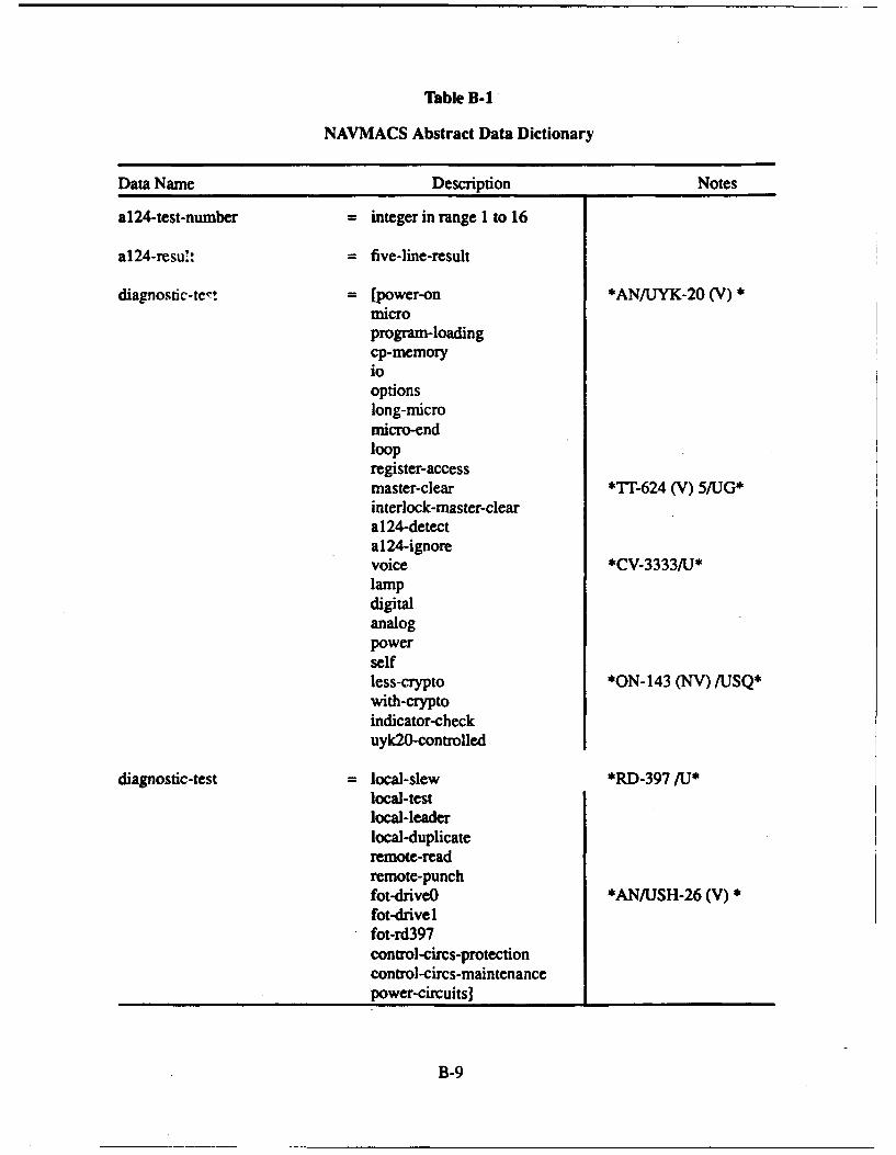
Table B-1
NAVMACS Abstract Data Dictionary
Data Name Description Notes
al24-test-number = integer in range 1 to 16
al 24-resul: = five-line-result
diagnostic-tert = [power-on *ANIJYK..20 (V)microprogram-loadingcp-memoryjooptionslong-micromicro-endloopregister-accessmaster-clear *Tl..624 (V) 5IUJG*interlock-master-clearal 24-detecta124-ignorevoice *CV..3333/TJ*lampdigitalanalogpowerselfless-crypto *ON-l43 (NV) /USQ*with-cryptoindicator-checkuyk2O-controlled
diagnostic-test =local-slew *RD..397 /U*'local-testlocal-leaderlocal-duplicateremote-readremote-punchfot-driveO *i&NfLJSH..26 (V)*fot-drive 1
*fot-rd397control-circs-protectioncontrol-circs-niaintenancepower-circuits] ____________
B-9
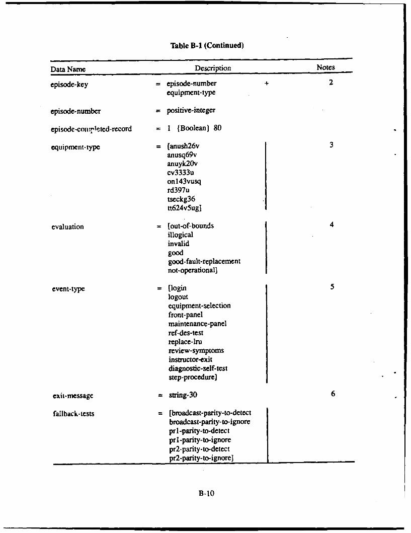
Table B-i (Continued)
Data Name Description Notes
episode-key = episode-number + 2equipment-type
episode-number = positive-integer
episode-conirleted-record = I (Boolean) 80
equipment-type = [anush26v 3anusq69vanuyk20vcv3333uonl43vusqrd397utseckg36tt624v5ug]
evaluation -[out-of-bounds 4illogicalinvalidgoodgood-fault-replacemnentnot-operational]
event-type -[login 5logoutequipment-selectionfront-panelmaintenance-panelref-des-testreplace-lrureview-symptomsinstructor-exitdiagnostic-self-teststep-procedure]
exit-message = string-30 6
faliback- tests = [broadcast-parity-to-detectbroadcast-parity-to-ignorepri -parity-to-detectpr 1-parity-to-ignorepr2-parity-to-detectpr2-parity-to-ignore] ___________
B-10
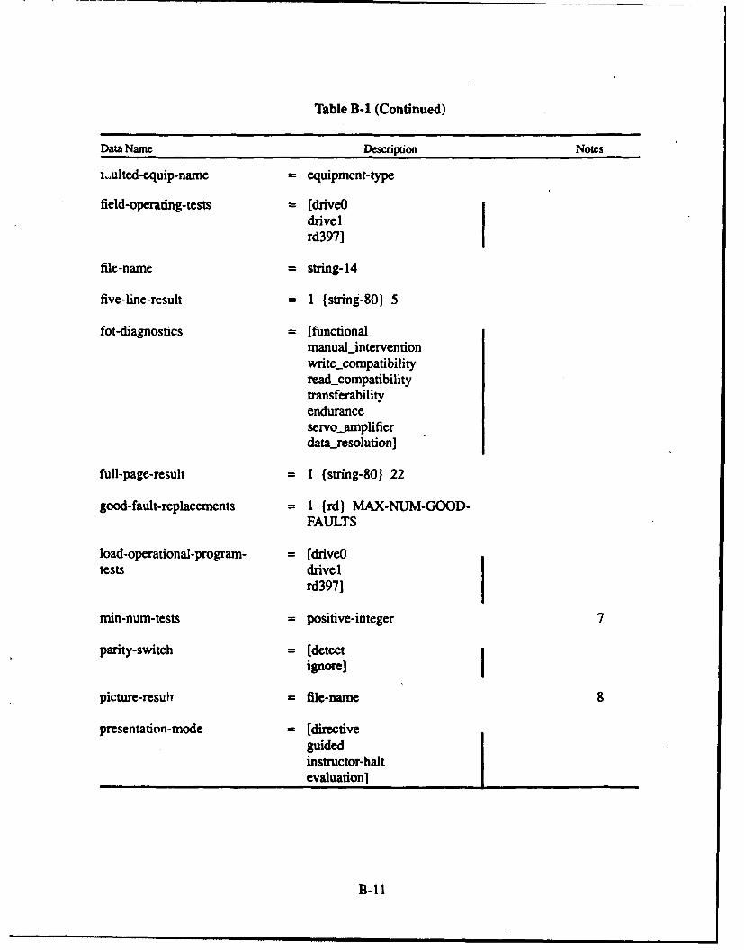
Table B-I (Continued)
Data Name Description Notes
i.ulted-equip-name = equipment-type
field-operating-tests = [driveOdrivelrd397]
file-name = string-14
five-line-result = 1 (string-80) 5
fot-diagnostics = [functionalmanualinterventionwrite_compatibilityreadcompatibilitytransferabilityenduranceservoamplifierdataresolution]
full-page-result = I (string-80} 22
good-fault-replacements = 1 (rd) MAX-NUM-GOOD-FAULTS
load-operational-program- = [driveOtests drivel
rd3971
min-num-tests = positive-integer 7
parity-switch = [detectignore]
picture-result = file-name 8
presentation-mode = [directiveguidedinstructor-haltevaluation]
B-11
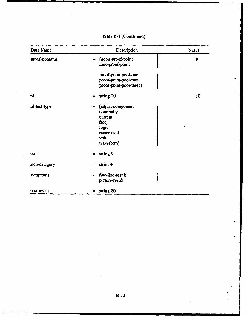
Table B-1 (Continued)
Data Name Description Notes
proof-pt-status -(not-a-proof-point 19lone-proof-point
proof-point-pool-oneproof-point-pool-twoproof-point-pool-three)
rd -strtng-20 10
rd-test-type [ adjust-componentcontinuitycurrentfreqlogicmeter-readvoltwaveform]
ssn -string-9
step-category -string-8
symptoms = five-line-resultpicture-result
text-result = string-80
B- 12
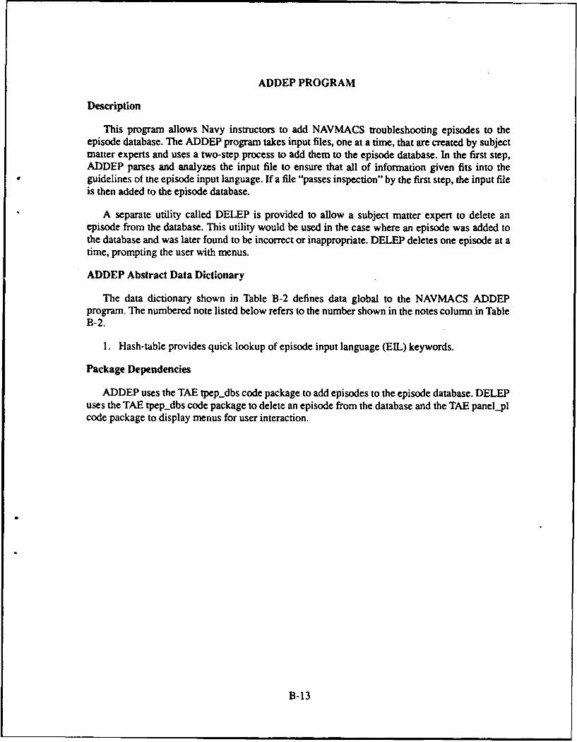
ADDEP PROGRAM
Description
This program allows Navy instructors to add NAVMACS troubleshooting episodes to theepisode database. The ADDEP program takes input files, one at a time, that are created by subjectmatter experts and uses a two-step process to add them to the episode database. In the first step,ADDEP parses and analyzes the input file to ensure that all of information given fits into theguidelines of the episode input language. If a file "passes inspection" by the first step, the input fileis then added to the episode database.
A separate utility called DELEP is provided to allow a subject matter expert to delete anepisode from the database. This utility would be used in the case where an episode was added tothe database and was later found to be incorrect or inappropriate. DELEP deletes one episode at atime, prompting the user with menus.
ADDEP Abstract Data Dictionary
The data dictionary shown in Table B-2 defines data global to the NAVMACS ADDEPprogram. The numbered note listed below refers to the number shown in the notes column in TableB-2.
1. Hash-table provides quick lookup of episode input language (ELL) keywords.
Package Dependencies
ADDEP uses the TAE tpep-dbs code package to add episodes to the episode database. DELEPuses the TAE tpepdbs code package to delete an episode from the database and the TAE panel-plcode package to display menus for user interaction.
B-13
Table B-2
ADDEP Abstract Data Dictionary
Data Name Description Notes
key = string-25
value = integer
hash-table-entry = key +value
hash-table 0 (hash-table-entry) 200
faulted-rd = rd
good-faults = good-fault-replacements
episode-data-record = episode-key +faulted-rd +good-faults +presentjnode +rmn-number-of-tests
episode-record = episode-data-record
front-panel = file-name
maintenance-panel = file-name
equipment-data-rec = episode-key +equipment-type +evaluation +front-panel +maintenance-panel
equipment-records = 0 (equipment-data-rec) 8
test-name = string- I
system-level-data-rec = episode-key +test-name +
evaluation +
text-result
system-level-records = 0 (system-level-data-rec) 9
step = string- I
register-access-grant = test-name +
step
B- 14
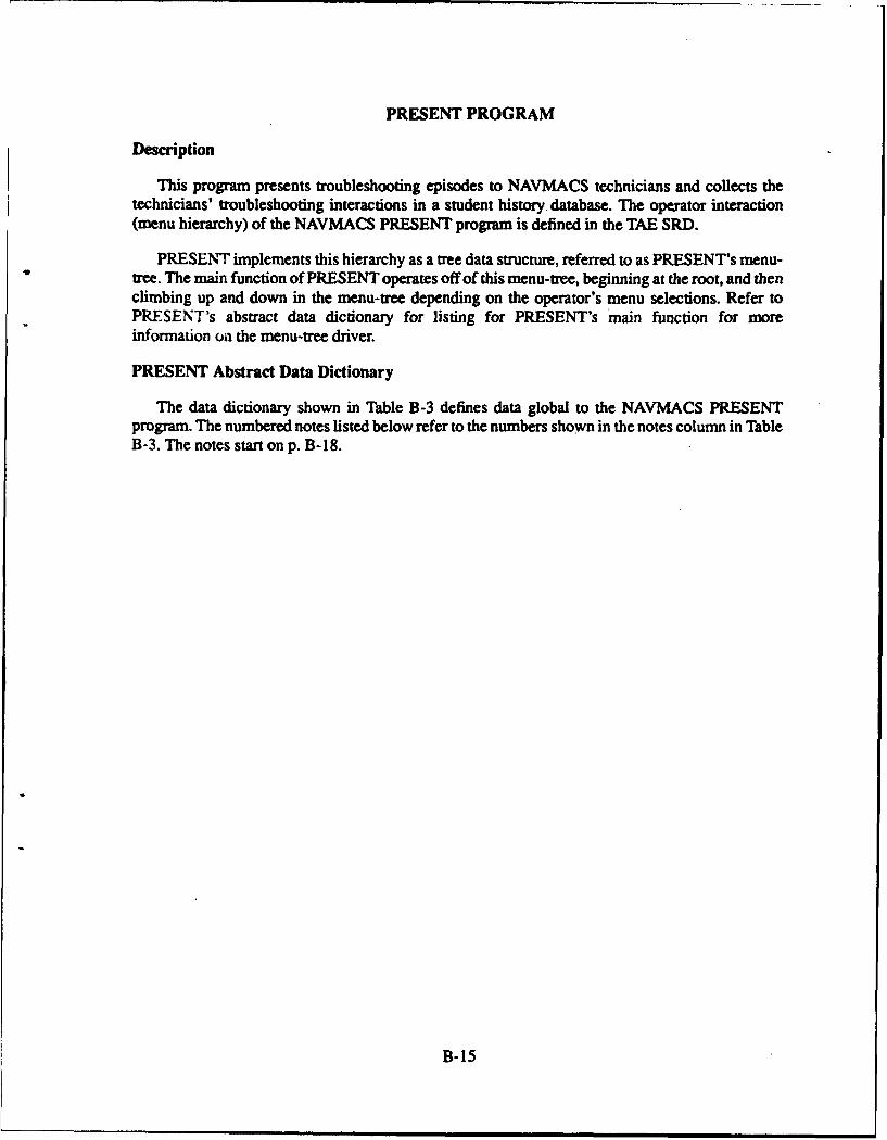
PRESENT PROGRAM
Description
This program presents troubleshooting episodes to NAVMACS technicians and collects thetechnicians' troubleshooting interactions in a student history database. The operator interaction(menu hierarchy) of the NAVMACS PRESENT program is defined in the TAE SRD.
PRESENT implements this hierarchy as a tree data structure, referred to as PRESENT's menu-tree. The main function of PRESENT operates off of this menu-tree, beginning at the root, and thenclimbing up and down in the menu-tree depending on the operator's menu selections. Refer toPRESENT's abstract data dictionary for listing for PRESENT's main function for moreinformation on the menu-tree driver.
PRESENT Abstract Data Dictionary
The data dictionary shown in Table B-3 defines data global to the NAVMACS PRESENTprogram. The numbered notes listed below refer to the numbers shown in the notes column in TableB-3. The notes start on p. B-18.
B-15
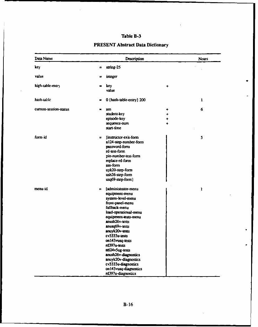
Table B-3
PRESENT Abstract Data Dictionary
Data Name Description Notes
key = string-25
value = integer
high-table-entr) = key +value
hash-tablc = 0 (hash-table-entry) 2001
current-session-status = ssn + 6student-key +episode-key +sequence-num +start-time
form-id = [instructor-exit-fonn 5a1,24-step-number-formnpassword-formnrd-test-formpin-number-test-formreplace-rd-formrsn-formuyk20-step-formush26-step-formusq69-step-form]
menu-id = [administrator-menuequipmnt-menusystem-level-menufront-panel-menufallback-menuload-operationa-menuequipment-tests-menuanush26v-testsanusq69v-testsanuyk20v-testcv3333u-testsonl43vusq-testsird397u-testst:624v~ug-testsanush2v-diagnosticsanuyk20v-diagnosticscv3333u-diagnosticsonl43vusq-diagnosticsrd.397u-diagnostics _____________
B-i16
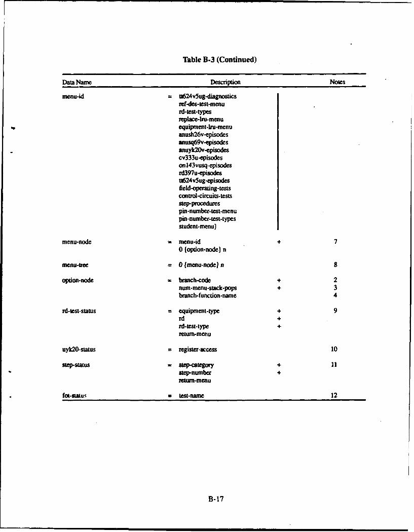
Table B-3 (Continued)
Data Name Description Notes
menu-id = t&624v5ug-diagnosticsref-des-test-menurd-lest-typesreplace-lIu-menuequipment-kru-menuanush26v-episodesanusq69v-episodesanuyk20v-epLsodescv333u-episodeson143vusq-episodesrd397u-episodestt624v5ug-episodesfield-operating-testscontrol-circuits-testsstep-procedurespin-number-test-menupin-number-test-typesstudent-menu]
menu-node = menu-id + 7o (option-node) n
menu-tree = 0 (menu-node) n 8
option-node = branch-code + 2num-menu-stack-pops + 3branch-function-name 4
rd-test-status = equipment-type + 9rd +rd-test-type +return-menu
uyk20-status = register-access 10
step-status = step-category + I Istep-number+return-menu
fot-Status = test-name 12
B- 17
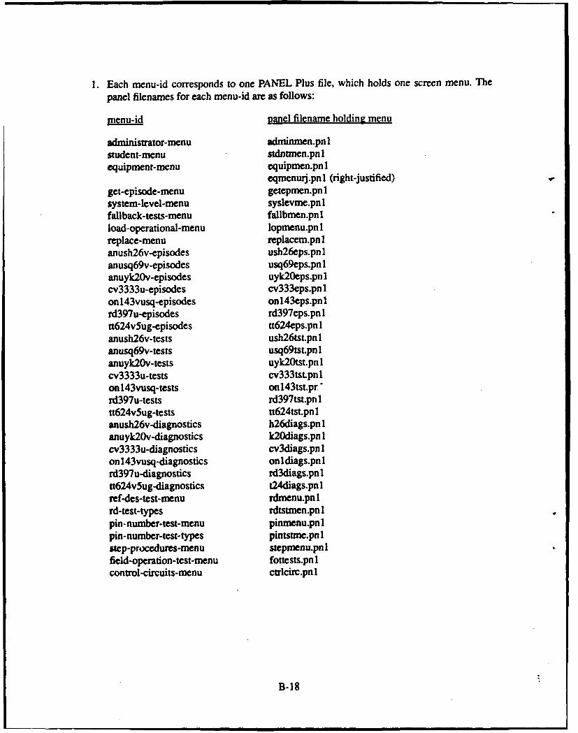
1. Each menu-id corresponds to one PANEL Plus file, which holds one screen menu. The
panel filenames for each menu-id are as follows:
menu-id Daflel filename holding menu
administrator-menu adminmen.pn Istudent-menu stdntinen.pn 1equipment-menu equipmen.pn 1
eqmnenurj.pn 1 (right-justified)get-episode-menu getepmen.pn 1system-level-menu syslevme.pnlfallback-tests-menu fallbmen.pn 1load-operational-menu Iopmenu.pn 1replace-menu replacem.pn Ianush26v-episodes ush26eps.pn 1anusq69v-episodes usq69eps.pn 1anuyk2Ov-episodes uyk2Oeps.pn 1cv3333u-episodes cv333eps.pnlon l43vusq-episodes onl43eps.pnlrd397 u-episodes rd397eps.pn 1tt624v5ug-episodes tt624eps.pn Ianush26v-tests ush26tst.pn Ianusq69v-tests usq69tst.pn Ianuyk2Ov-tests uyk2Otst.pn 1cv3333u-tests cv333tSt~pn 1onl43vusq-tests onl43tst.pr'rd397u-tests rd397tst.pn 1tt624v5ug-tests tt624tst.pnlanusb26v-diagnostics h26diags.pn Ianuyk2Ov-diagnostics k2Odiags.pn Icv3333u-diagnostics cv3diags.pn Ionl143vusq-diagnostics onldiags.pnlrd397u-diagnostics rd3diags.pnltt624v5ug-diagnostics t24diags.pn 1ref-des-test-menu rdmenu.pnlrd-test-types rdtstmen.pn Ipin-number-test-menu pinmenu.pn Ipin-number-test-types pintstme.pn 1step-procedures-menu stepmenu.pn Ifield-operation-test-menu fottests.pn 1control-circuits-menu ctrlcirc.pn 1
B-18
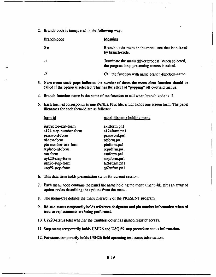
2. Branch-code is interpreted in the following way:
Branch-code Meaning
0-n Branch to the menu in the menu-tree that is indexedby branch-code.
-1 Terminate the menu driver process. When selected,the program loop presenting menus is exited.
-2 Call the function with name branch-function-name.
3. Num-menu-stack-pops indicates the number of times the menu clear function should becalled if the option is selected. This has the effect of "popping" off overlaid menus.
4. Branch-function-name is the name of the function to call when branch-code is -2.
5. Each form-id corresponds to one PANEL Plus file, which holds one screen form. The panelfilenames for each forn-id are as follows:
form-id panel filename holding menu
instructor-exit-form exitform.pn 1al 24-step-number-form al24form.pn 1password-form password.pn 1rd-test-form rdform.pn 1pin-number-test-form pinform.pn 1replace-rd-form reprdfrm.pn 1ssn-form ssnform.pn 1uyk20-step-form stepform.pn 1ush26-step-form h26stfrm.pnlusq69-step-form q69stfrm.pn 1
6. This data item holds presentation status for current session.
7. Each menu node contains the panel file name holding the menu (menu-id), plus an array ofoption-nodes describing the options from the menu.
8. The menu-tree defines the menu hierarchy of the PRESENT program.
9. Rd-test-status temporarily holds reference designator and pin number information when rdtests or replacements are being performed.
10. Uyk2O-status tells whether the troubleshooter has gained register access.
11. Step-status temporarily holds USH26 and USQ 69 step procedure status information.
12. Fot-status temporarily holds USH26 field operating test status information.
B-19
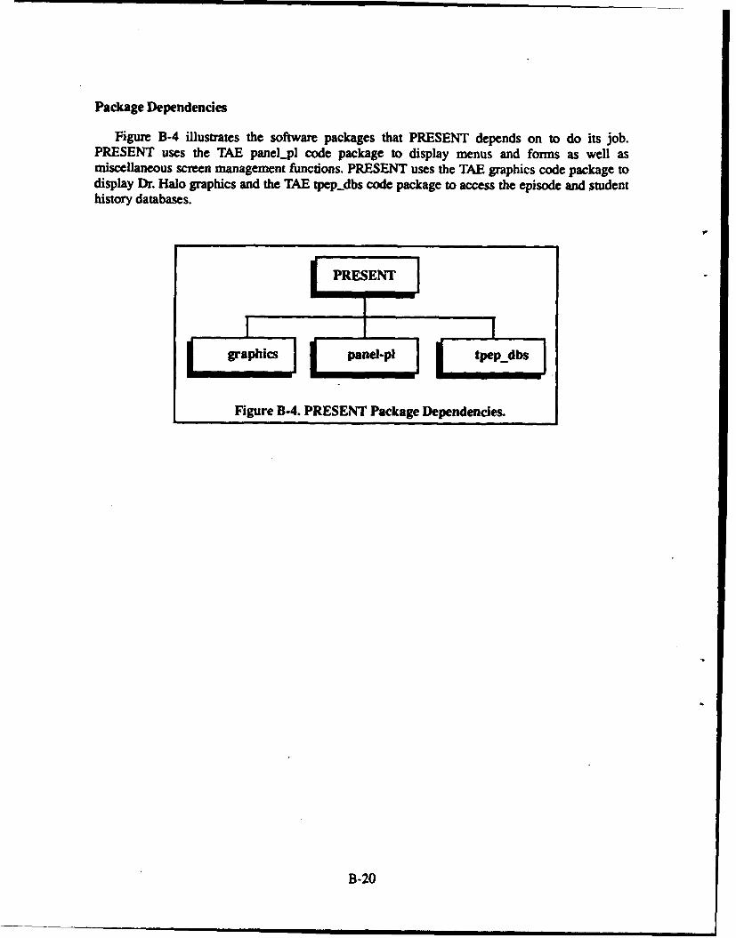
Package Dependencies
Figure B-4 illustrates the software packages that PRESENT depends on to do its job.PRESENT uses the TAE panelpl code package to display menus and forms as well asmiscellaneous screen management functions. PRESENT uses the TAE graphics code package todisplay Dr. Halo graphics and the TAE tpep.dbs code package to access the episode and studenthistory databases.
PRESENT-
graphics_gaEpanel-pi te..b
Figure B-4. PRESENT Package Dependencies.
B-20
EDITVIEW PROGRAM
Description
The EDITVIEW program has a menu-driven user interface. EDITVIEW is implemented incode as eight separate compilation packages. One of these packages, Edithist.pak, uses a menu-treestructure as in PRESENT for presenting the menus to the user. The other packages do not use amenu-tree structure, but call up the various menus within the individual routines. Here are thenames and functions of the eight compilation packages:
1. Edit, icw.pak contains the main routines for invoking the various features available to theuser and for driving the "print multiple histories" feature. This package also has the routinesfor deleting a student from the student history database and for implementing the displaysummarizing each student's final scores, and for displaying the overall class average score.
2. Scord-s.pak contains the code for calculating, displaying, and printing a student's scoredanalysis for a given episode history.
3. Author-s.pak contains the code for allowing the user to author scoring constants andweights to be used in conducting the scored analysis of a sequence of events.
4. Sequence.pak contains the code for displaying and printing one sequence of events.
5. Archival.pak contains the code for archiving student history databases and retrieving them.
6. Combine.pak contains the code for transferring a student history database to a floppydiskette and for combining two different student history databases into one database.
7. Edithist.pak contains the routines for allowing Navy instructor to edit a student's sequenceof events.
8. Statistic.pak contains the routines for translating the data in the student history databaseinto a data file for the Microstat statistical analysis software package.
EDITVIEW Abstract Data Dictionary
The data dictionary shown in Table B-4 defines data global to the NAVMACS ED1TVIEWprogram The numbered note listed below refers to the number in the notes column in Table B-4.
B-21
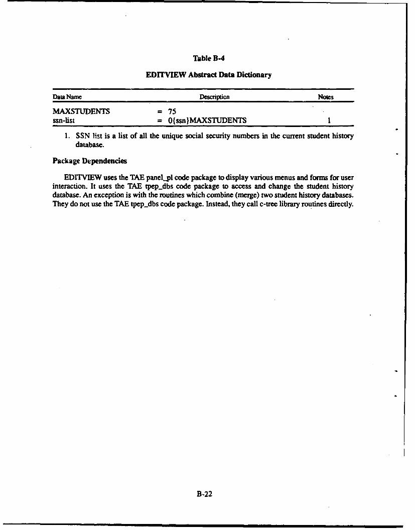
Table B-4
EDITVIEW Abstract Data Dictionary
Data Name Description Notes
MAXSTUDENTS = 75ssn-list = Ossn)MAXSTUDENTS 1
1. SSN list is a list of all the unique social security numbers in the current student historydatabase.
Package Dependencies
EDrTVIEW uses the TAE paneLpl code package to display various menus and forms for userinteraction. It uses the TAE tpepdbs code package to access and change the student historydatabase. An exception is with the routines which combine (merge) two student history databases.They do not use the TAE tpep-dbs code package. Instead, they call c-tree library routines directly.
B-22
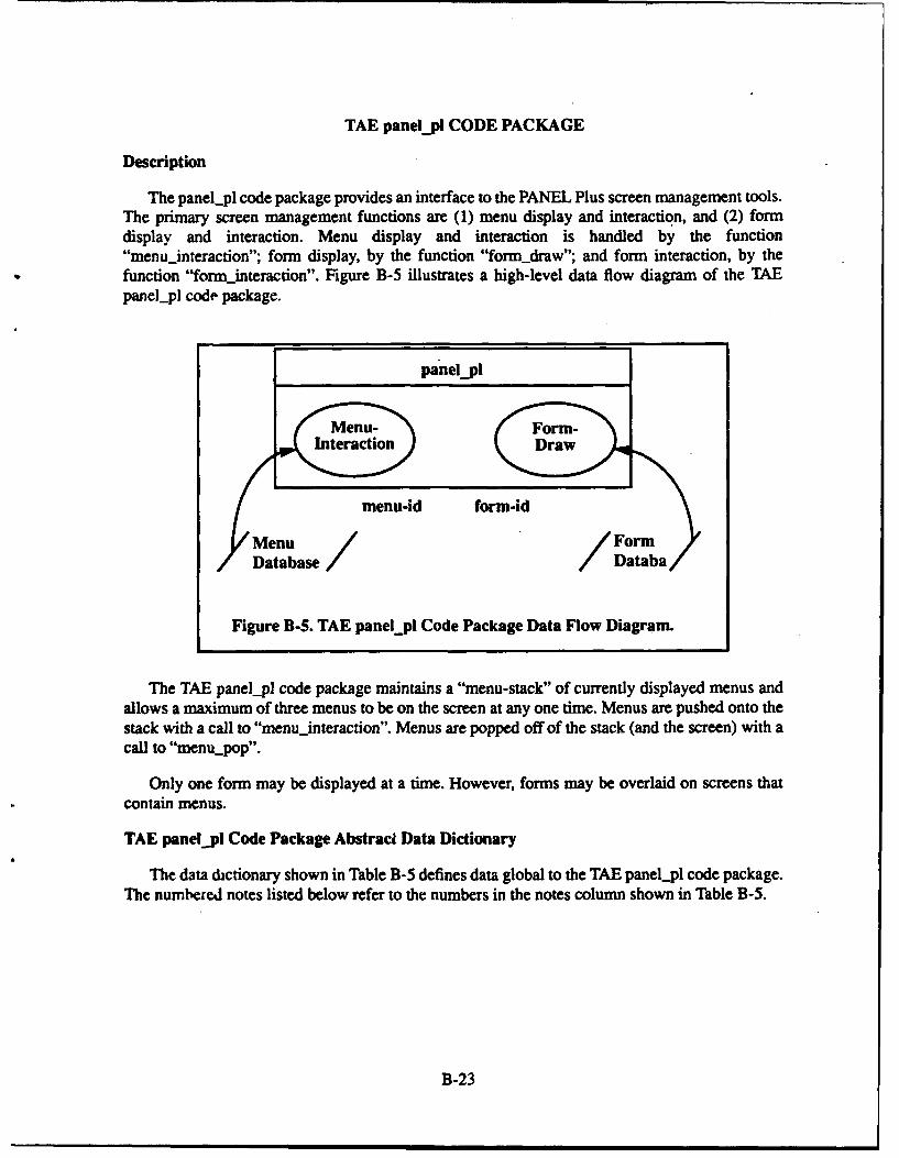
TAE panel.pl CODE PACKAGE
DescriptionThe panelpl code package provides an interface to the PANEL Plus screen management tools.
The primary screen management functions are (1) menu display and interaction, and (2) formdisplay and interaction. Menu display and interaction is handled by the function"menuinteraction"; form display, by the function "formdraw"; and form interaction, by thefunction "form_interaction". Figure B-5 illustrates a high-level data flow diagram of the TAEpanel-pl code package.
panel.pl
Menu- Form-Interaction Draw
menu-id form-id
Menu / / FormDatabase / Databa
Figure B-S. TAE panel_pl Code Package Data Flow Diagram.
The TAE panel-pl code package maintains a "menu-stack" of currently displayed menus andallows a maximum of three menus to be on the screen at any one time. Menus are pushed onto thestack with a call to "menuinteraction". Menus are popped off of the stack (and the screen) with acall to "menu-pop".
Only one form may be displayed at a time. However, forms may be overlaid on screens thatcontain menus.
TAE panel pl Code Package Abstract Data Dictionary
The data dictionary shown in Table B-5 defines data global to the TAE panel._pl code package.The numbered notes listed below refer to the numbers in the notes column shown in Table B-5.
B-23
Table B-5
TAE panel_pl Code Package Abstract Data Dictionary
Data Name Description Notes
form = panel-plus-control-block
menu-definition = panel-plus-control-block + Iinternal-field-control-block +current-selection
menu-stack - top + 20 (menu-definition) NUM-OVERLAYS
1. Each menu-definition is represented in two formats. The higher-level format (panel-plus-control-block) describes the characteristics of the panel file (".pn 1" file) that holds themenu. The lower-level format (internal-field-control-block) describes the menu itself inspecific detail. By convention, each PANEL Plus file that will hold a menu has only onefield: a multiline field that will act as a menu. panel-plus-control-block and internal-field-control-block are panel plus data structures. Their coded structure names are "panpcb" and"ifcb", respectively. They are described in greater detail in the PANEL Plus user's manual.Current-selection is used to hold the latest selection made from the menu.
2. The menu-stack holds all currently displayed menus. If only one menu is currentlydisplayed, the menu-stack will only have one entry. The menu-stack grows as menus areoverlaid on top of one another. There is a limit to the size of the menu-stack, defined byNUM-OVERLAYS. For correct stack management, menu pushes must be matched withmenu pops. The top of the menu-stack will point to the next open slot of the menu-stack.The stack is empty when top of menu-stack equals zero. The stack is full when top of menu-stack = NUM-OVERLAYS.
PANEL Plus Conventions
The TAE panel-pl code package is implemented with the PANEL Plus commercial softwarepackage. The PANEL Plus package is a character-based form and menu package. On the targethardware, it operates with the EGA card in text mode 3, providing a character resolution of 80 x25, with 16 foreground and 8 background colors. The following lists specific conventions adoptedwith PANEL Plus:
1. TAE uses the pre-configured version of PANEL Plus for the IBM PC. Since this pre-configuration is used, the "tailor" program is not necessary. The name of the screen editorfor the IBM version of PANEL Plus is "panelpi". The name of the screen test program forthe IBM version of PANEL Plus is "pantesti".
B-24
2. Colors are defined by a DOS environment variable, PAIAT, set with the followingcommand:
"set PAIATr=1F7 I 1C797B7F060708090AOBOCODOEOF'.
3. This string is interpreted as 16 2-digit, unsigned hexadecimal numbers, corresponding tothe 16 highlight types (colors) provided by the PANEL Plus editor. The highlight typesdefined for TAE, as generated by the values of the PAIATT variable are listed below. ThePANEL Plus User's Manual describes the correspondence of hexadecimal numbers tocolorq for the IBM PC.
Highlight PAIAIIType Value Color
0 IF Bright White On Blue1 71 Blue On White2 IC Bright Red On Blue3 79 Bright Blue On Grey4 7B Bright Cyan On Grey5 7F Bright White On Grey6 06 Brown On Black7 07 Light Grey (White) On Black8 08 Dark Grey On Black9 09 Light Blue On Black
10 OA Light Green On Black11 OB Light Cyan On Black12 0C Light Red On Black13 OD Light Magenta On Black14 OE Yellow On Black15 OF Bright White On Black
4. The first six highlight types have the following special meaning:
* Highlight type 0 (bright white on blue) = the default screen color attributes.
0 Highlight type 1 (blue on white) = inverse video from the default screen color attributes.
0 Highlight type 2 (light red on blue) = color of the menu highlight bar.
• Highlight type 3 (bright blue on grey) = color of an event "tagged" for deletion in theedit mode of EDITVIEW.
* Highlight type 4 (bright cyan on grey) = color of a "highlighted" event which is also"tagged" for deletion in the edit mode of ED1TVIEW.
• Highlight type 5 (bright white on grey) = color of a "highlighted" event during deletionof events in the edit mode of EDITVIEW.
B-25
In addition to these 16 highlight types, other color effects can be generated using the paneleditor's "highlight modifiers". The highlight modifiers defined for TAE are listed below. Highlightmodifiers can be added together, creating still more color effects. For example, a highlight modifierof 224 (128 + 96) would blink the foreground (128) on top of a yellow background (96).
Highlight Modifier Effect
0 None16 Blue Background32 Green Background48 Cyan Background64 Red Background82 Magenta Background96 Yellow Background
112 White Background128 Blinking Foreground
Menus are built by creating a multiline field with the panel editor. Each line of the fieldcorresponds to an option from the menu. Each menu must reside in its own panel file. The menumust be authored on level zero of the panel.
Forms are also created with the panel editor, one form per file. The fields of the form must beauthored on level one of the panel. A border surrounding the entire form must be authored on leveltwo of the panel.
TAE displays menus and forms using the "dynamic load" function (paload) of PANEL Plus.
Application programs must link to the special IBM library, "panelpi.lib", as well as the usualPANEL Plus library, "panelp.lib". In the link statement, "panelpi.lib" should be placed before"panelp.lib".
B-26
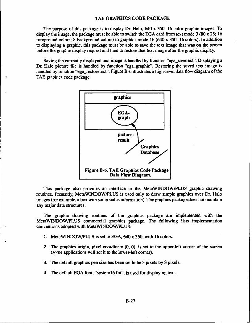
TAE GRAPHICS CODE PACKAGE
The purpose of this package is to display Dr. Halo, 640 x 350, 16-color graphic images. Todisplay the image, the package must be able to switch the EGA card from text mode 3 (80 x 25; 16foreground colors; 8 background colors) to graphics mode 16 (640 x 350; 16 colors). In additionto displaying a graphic, this package must be able to save the text image that was on the screenbefore the graphic display request and then to restore that text image after the graphic display.
Saving the currently displayed text image is handled by function "egasavetext". Displaying aDr. Halo picture file is handled by function "ega-graphic". Restoring the saved text image ishandled by function "egarestoretext". Figure B-6 illustrates a high-level data flow diagram of theTAE graphics code package.
graphics
EGA-graph
picture-result
GraphicsDatabas
Figure B-6. TAE Graphics Code PackageData Flow Diagram.
This package also provides an interface to the MetaWINDOW/PLUS graphic drawingroutines. Presently, MetaWINDOW/PLUS is used only to draw simple graphics over Dr. Haloimages (for example, a box with some status information). The graphics package does not maintainany major data structures.
The graphic drawing routines of the graphics package are implemented with theMetaWINDOW/PLUS commercial graphics package. The following lists implementationconventions adopted with MetaWINrDOW/PLUS:
1. MetaWINDOW/PLUS is set to EGA, 640 x 350, with 16 colors.
2. Thr. graphics origin, pixel coordinate (0, 0), is set to the upper-left corner of the screen(some applications will set it to the lower-left corner).
3. The default graphics pen size has been set to be 3 pixels by 3 pixels.
4. The default EGA font, "systeml6.fnt", is used for displaying text.
B-27
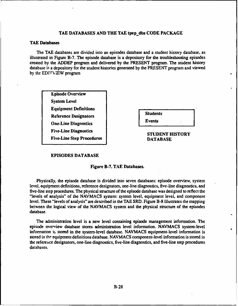
TAE DATABASES AND THE TAE tpepdbs CODE PACKAGE
TAE Databases
The TAE databases are divided into an episodes database and a student history database, asillustrated in Figure B-7. The episode database is a depository for the troubleshooting episodescreated by the ADDEP program and delivered by the PRESENT program. The student historydatabase is a depository for the student histories generated by the PRESENT program and viewedby the EDITVIEW program
Episode Overview
System Level
Equipment Definitions
Reference Designators Students
One-Line Diagnostics Events
Five-Line Diagnostics STUDENT HISTORY
Five-Line Step Procedures DATABASE
EPISODES DATABASE
Figure B-7. TAE Databases.
Physically, the episode database is divided into seven databases: episode overview, systemlevel, equipment definitions, reference designators, one-line diagnostics, five-line diagnostics, andfive-line step procedures. The physical structure of the episode database was designed to reflect the"levels of analysis" of the NAVMACS system: system level, equipment level, and componentlevel. These "levels of analysis" are described in the TAE SRD. Figure B-8 illustrates the mappingbetween the logical view of the NAVMACS system and the physical structure of the episodesdatabase.
The administration level is a new level containing episode management information. Theepisode overview database stores administration level information. NAVMACS system-levelinformation is stored in the system-level database. NAVMACS equipment-level information isstored in the equipment definitions database. NAVMACS component-level information is stored inthe reference designators, one-line diagnostics, five-line diagnostics, and five-line step proceduresdatabases.
B-28
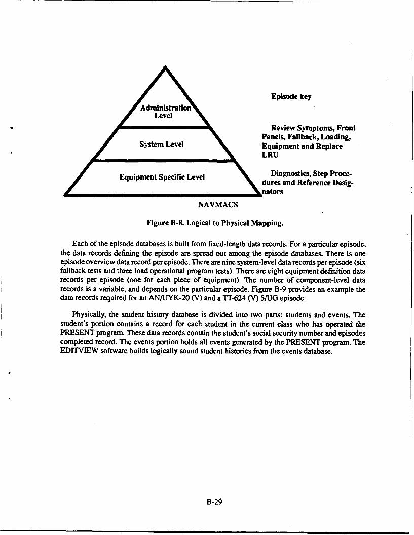
Episode key
Level
Review Symptoms, FrontPanels, Fallback, Loading,
System Level Equipment and ReplaceLRU
Equipment Specific Level Diagnostics, Step Proce-dures and Reference Desig-
nators
NAVMACS
Figure B-8. Logical to Physical Mapping.
Each of the episode databases is built from fixed-length data records. For a particular episode,the data records defining the episode are spread out among the episode databases. There is oneepisode overview data record per episode. There are nine system-level data records per episode (sixfallback tests and three load operational program tests). There are eight equipment definition datarecords per episode (one for each piece of equipment). The number of component-level datarecords is a variable, and depends on the particular episode. Figure B-9 provides an example thedata records required for an AN/UYK-20 (V) and a TI'-624 (V) 5/UG episode.
Physically, the student history database is divided into two parts: students and events. Thestudent's portion contains a record for each student in the current class who has operated thePRESENT program. These data records contain the student's social security number and episodescompleted record. The events portion holds all events generated by the PRESENT program. TheEDITVIEW software builds logically sound student histories from the events database.
B-29
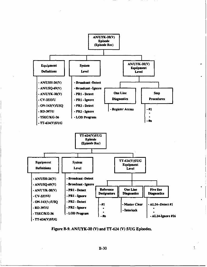
AN/UYK.20(V)Episode
(Episode Rec)
Equaipment system Eq/UipmentV
Defiitins LvelLevel
- A.N/USH-26(V) - Broadcast -Detect
- ANIUSQ-69(V) - Broadcast - Ignore
. AN/UYK-20(V) - PR1 - Detect One Line Step
- CV-33331U - PRI - Ignore Diagnostics Procedures
* ON-143(V)/USQ - PR2 - Detect
- RD-397/U - PR2 - Ignore - Register Access -#1
- TSEC/KG-36 - LOD Program
. T624(V)S/UG #n
TTT(24(V)S/(GEpisode
(Episode Rec)
Equipment System TT-624(V)S/UG
EquipmentDefinitions Level Level
- AN/USH-26(V) - Broadcast -Detect
. AN/USQ-69(V) - Broadcast- Ignore
. AN/tUYK-20(V) - FRI, - Detect Reference One Line Five line
-CV-333VU - PRI -Ignore Designators Diagnostics Diagnostics
- ON- 143(N)/USQ - PR2 -Detect .#1 - Master Clear - AL24-.Detect #1RD-397/U - PR2. Ignore Interlock"
- TSECIKG-36 - LOD Program -L24-Ignore #16
- Tr-624(V)S/UG
Figure B-9. AN/UYK-20 (V) and TT-624 (V) 5/UG Episodes.
B-30
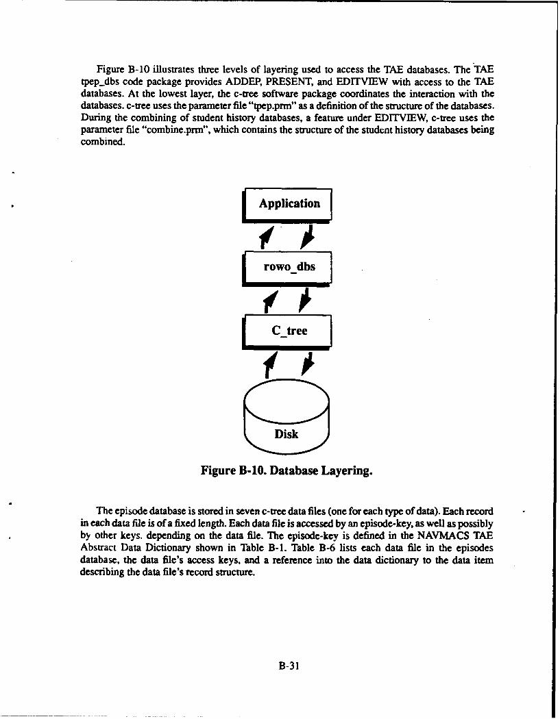
Figure B-10 illustrates three levels of layering used to access the TAE databases. The TAEtpep-dbs code package provides ADDEP, PRESENT, and EDITVIEW with access to the TAEdatabases. At the lowest layer, the c-tree software package coordinates the interaction with thedatabases, c-tree uses the parameter file "tpep.prm" as a definition of the structure of the databases.During the combining of student history databases, a feature under EDITVIEW, c-tree uses theparameter file "combine.prm", which contains the structure of the student history databases beingcombined.
Application
'(Aobs
Disk
Figure B-1O. Database Layering.
The episode database is stored in seven c-tree data files (one for each type of data). Each recordin each data file is of a fixed length. Each data file is accessed by an episode-key, as well as possiblyby other keys. depending on the data file. The episode-key is defined in the NAVMACS TAEAbstract Data Dictionary shown in Table B-1. Table B-6 lists each data file in the episodesdatabase, the data file's access keys, and a reference into the data dictionary to the data itemdescribing the data file's record structure.
B-31
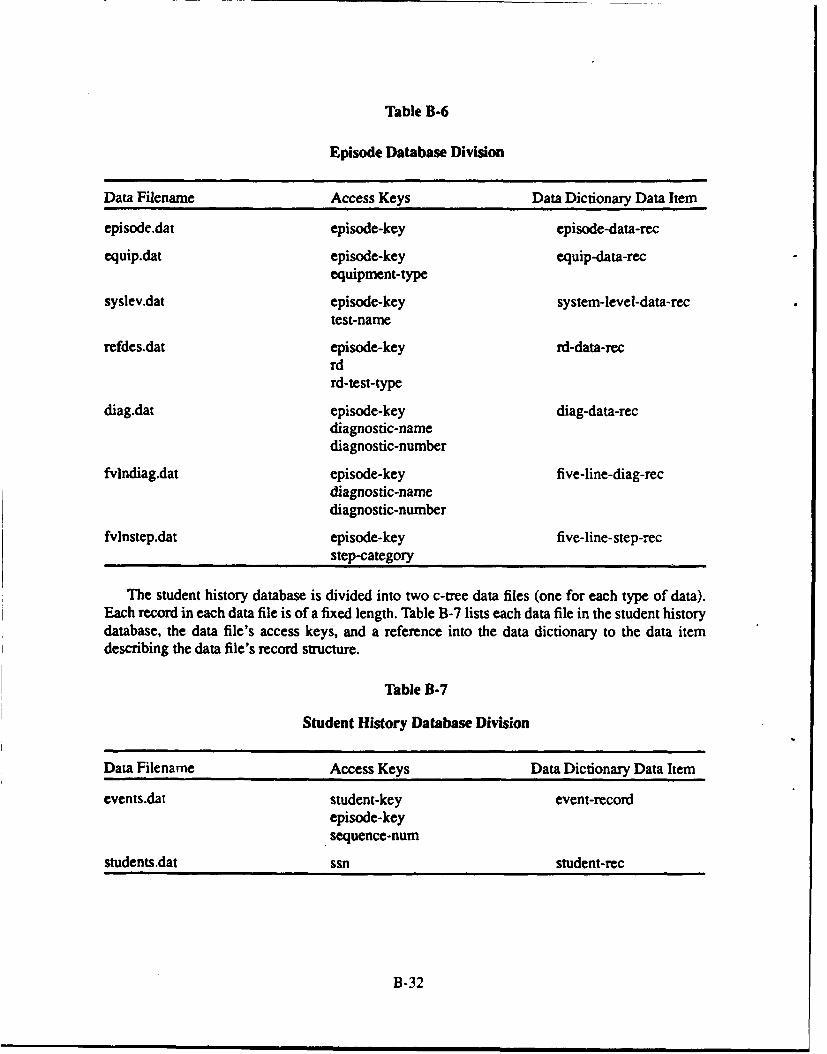
Table B-6
Episode Database Division
Data Filename Access Keys Data Dictionary Data Item
episode.dat episode-key episode-data-rec
equip.dat episode-key equip-data-recequipment-type
syslev.dat episode-key system-level-data-rectest-name
refdes.dat episode-key rd-data-recrdrd-test-type
diag.dat episode-key diag-data-recdiagnostic-namediagnostic-number
fvlndiag.dat episode-key five-line-diag-recdiagnostic-namediagnostic-number
fvlnstep.dat episode-key five-line-step-recstep-category
The student history database is divided into two c-tree data files (one for each type of data).Each record in each data file is of a fixed length. Table B-7 lists each data file in the student historydatabase, the data file's access keys, and a reference into the data dictionary to the data itemdescribing the data file's record structure.
Table B-7
Student History Database Division
Data Filename Access Keys Data Dictionary Data Item
events.dat student-key event-recordepisode-keysequence-numi
students.dat ssn student-rec
B-32

The episode and student history databases are opened by a call to the function"opendatabases". The "combine" feature under EDITVIEW opens the student history databaseswith a call to function "openjdbs". Each data file is associated with two functions: "read-data-record" and "write-data-record". "Read-data-record" reads one data record from the specified datafile; "write-data-record" writes one data record to the specified data file. The episode and studenthistory databases are closed by a call to function "closedatabases". The "combine" feature closesits student history database files with a call to "close_dbs". Figure B-Il illustrates a high-level dataflow diagram of the TAE tpep-dbs code package.
tpepdbs
Database/open- Structure /databases Definition ]
(tpep.prm) /
read- write-data- data-record record
Episode fStudent jDatabase History
Database
Figure B-11. TAE tpepdbs Code Package Data Flow Diagram.
The TAE tepe.dbs code package also exports a function called "vf.close", standing for virtualfile close. One quirk with c-tree is that it hogs DOS file descriptors. Calling "vfclose" forces c-tree to free up a file descriptor, so that an application program may perform disk input/outputindependent of c-tree.
TAE tpepdbs Code Package Abstract Data Dictionary
The data dictionary shown in Table B-8 defines data global to the TAE tpep.dbs code package.The numbered notes listed below refer to the numbers in the notes column shown in Table B-8.Refer to the NAVMACS TAE Abstract Data Dictionary in Table B- 1 for many of the data types notdefined here.
B-33
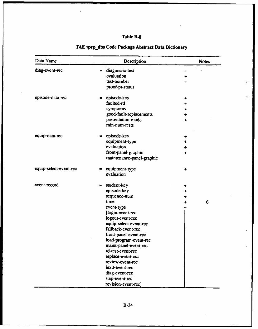
Table B-8
TAE tpep dbs Code Package Abstract Data Dictionary
Data Name Description Notes
diag-event-rec =diagnostic-test +evaluation +test-number +proof-pt-status
episode-data rec =episode-key +faulted-rd +symptoms +good-fault-replacements +presentation-mode +min-num-tests
equip-data-rec =episode-key +equipment-type +evaluation +front-panel-graphic +maintenance-panel-graphic
equip-select-event-rec = equipment-type +evaluation
event-record = student-key +episode-key +sequence-num +time + 6event-type +[login-event-reclogout-event-recequip-select-event-recfallback-event-recfront-panel-event-recload-prograni-event-recmaint-panel-event-recrd-test-event-recreplace-event-recreview-event-reciexit-event-recdiag-event-recstep-event-recrevision-event-rec ________
B-34
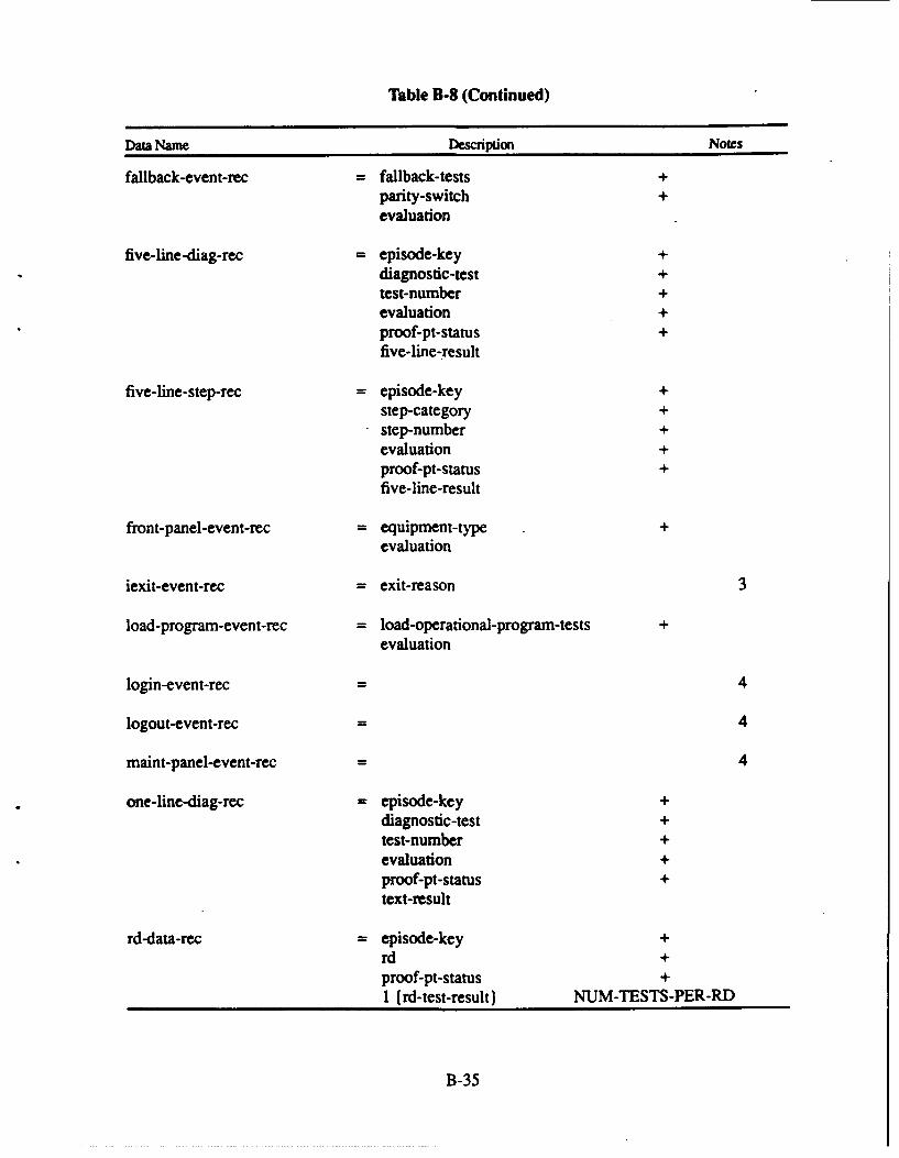
Table B-8 (Continued)
Data Name Description Notes
failback-event-rec = faliback-tests +parity-switch +evaluation
five-line -diag-rec = episode-key +diagnostic-test +test-number +evaluation +proof-pt-status +five-line-.result
five-line-step-rec =episode-key +step-category +step-number +evaluation +proof-pt-status +five-line-result
front-panel-event-rec = equipment-type +
evaluation
iexit-event-rec = exit-reason 3
load-prograni-event-rec = load-operational-program-tests +
evaluation
login-event-rec 4
logout-event-rec 4
maint-panel-event-rec 4
one-line-diag-rec =episode-key +diagnostic-test +test-number +evaluation +proof-pt-status +text-result
rd-data-rec =episode-key +rd +proof-pt-status +1 (rd-test-result) NUM-TESTS -PER-RD
B-35
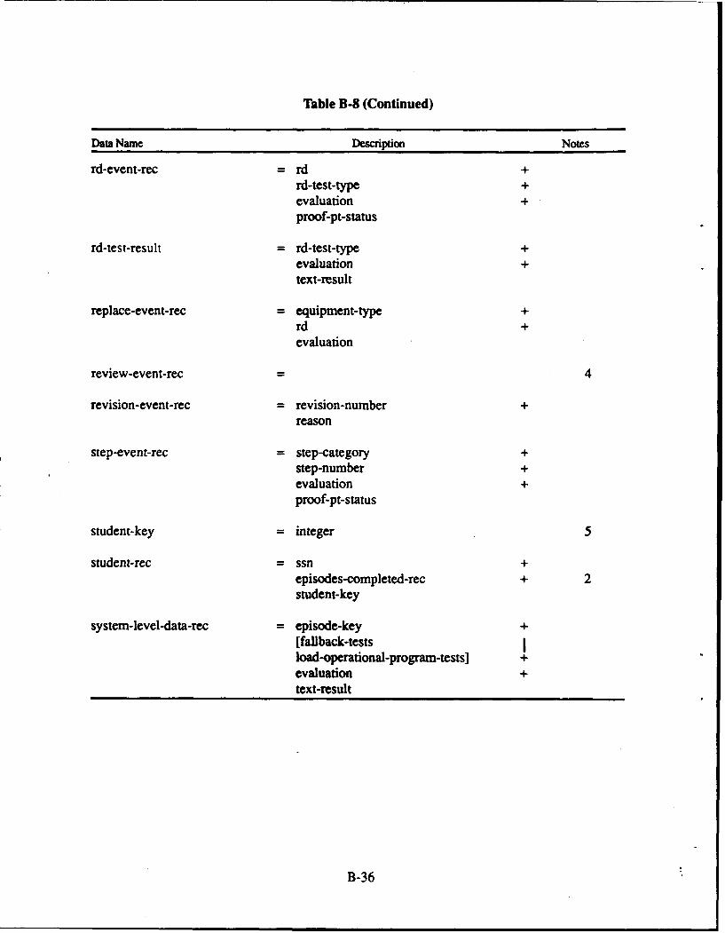
Table B-8 (Continued)
Data Name Description Notes
rd-event-rec -rd +rd-test-type +evaluation +proof-pt-status
rd-test-result = rd-test-type +evaluation +text-result
replace-event-rec = equipment-type +rd +evaluation
review-event-rec4
revision-event-rec = revision-number +
reason
step-event-rec = step-category +step-number +evaluation +proof-pt-status
student-key = integer 5
student-rec = ssn +episodes-completed-rec + 2student-key
system-level-data-rec = episode-key +[failback-tests Iload-operational-program-tests] +evaluation +text-result
B-36

2. The episodes completed record is an array of bytes that keeps a record of which episodes astudent has completed. There is one episodes completed record per student.NUM_EPISODES holds the total number of episodes available in the TAE system.
3. An instructor exit event is recorded when the instructor has prematurely terminated apresentation session. The instructor exit event holds the reason the instructor terminated thesession.
4. This event type requires no additional status information; it is sufficient just to list that theuser performed the event.
5. Student-key is a unique id number for a student. It will be the last four digits from thestudent's social security number.
6. Event time resolution is only kept to minutes. Both hours and minutes will be positiveintegers. The first event occurs at time zero hours, zero minutes. Minutes range from zeroto 59.
c-tree Conventions
The TAE tpep.dbs code package is implemented using routines provided in the c-treecommercial software package. The c-tree software package is compiled into two different libraryfiles:
1. ctreefst.lib, which buffers index file updates and writes them to disk as needed.
2. ctree.lib, which immediately forces all index file updates to disk. Applications linked withctree.lib will run slower than applications that are linked with ctreefst.lib.
This is a list of implementation conventions adopted with c-tree:
1. Only the ISAM (Indexed Sequential Access Method) routines are used.
2. All data records are of fixed length (no variable-length data records).
3. The c-tree parameter file "tpep.prm" describes the structure of all TAE databases.
4. The c-tree parameter file "combine.prm" describes the structure of the student historydatabases that it merges together.
5. The PRESENT and ADDEP programs are linked with ctree.lib.
6. The EDITVIEW program is linked with ctreefst.lib to speed up execution.
B-37
TAE LOCAL AREA NETWORK DESIGN AND IMPLEMENTATION
The Omninet local area network (LAN) by Corvus Systems is used to create a networkingenvironment for TAE. each computer connected to the LAN is referred Lo as a "node". CorvusSystems provides its PC/NOS network operating software as part of Omninet. PC/NOS must beinstalled on each computer before the computer is attached to the LAN. The Omninet hardwaremust also be installed in each computer, and cables must be connected to the computers to createthe connections that form the physical portion of the LAN. Once the Omninet software andhardware are properly installed, logical connections between the nodes must be defined to allowfor hard disk sharing. The Omninet LAN together with custom TAE batch fi.,;s affords thefollowing advantages over using TAE without them:
1. An instructor working at one node may specify troubleshooting episodes for specificstudents to run at the remote nodes.
2. An instructor working at one node may access and edit student history databases located atremote nodes.
The following steps explain how to set up the Omninet LAN:
1. Connect each computer to the LAN using the Corvus hardware. This involves (a) installingthe Omninet Transporter Network Interface Card according to the instructions in theCorvus Installation and User Guides booklet and (b) installing the cabling according to theinstructions in the Omninet Cabling System II Installation Guide.
2. Install the PCINOS network operating system software on ALL nodes in the "shared disk"configuration according to the instructions in the "Installation" sectioai of the PCINOSSystem Manager's Guide.
3. Designate one node as the "administrator node". The classroom instructor will use thiscomputer to deliver troubleshooting episodes to the students on their remote nodes, andmay also access the student history databases on remote nodes for use with the EDITVIEWprogram.
4. Create connections to all remote hard disks on the LAN from the administrator node. Eachcomputer on the network should refer to its own hard disk as "C:". The hard disk drives onremote machines are referred to as drives "D:" through "M:". The hard drive known as "D:"to a remote machine will be referred to as "D:" by all remote machines; likewise for drives"E:" through "M:". If a computer already refers to a partition on its hard disk as the "D:"drive, make sure not to use "D:" as one of the network drive names for referring to remotemachines. These logical connections (known as "plugs and sockets" under PC/NOS) canbe made using the PCINOS Netview program. Refer to the "Making Connections" sectionin the PC/NOS System Manager's Guide to create these plugs and sockets. If theadministrator node ever experiences a crash, the instructor may use any other node as anadministrator node, provided that the substitute node also has plugs to every other hard diskon the LAN. For maximum flexibility, configure every node so that it has plugs to everyother node's hard disk, following the naming scheme explained above.
B-38
5. Invoke the PC/NOS operating system once the LAN is installed. Refer to the "GeneralTasks" section of the PC/NOS System Manager's Guide to log on and log off the LAN ateach node.
6. Move all four files from the C:\TPEINRUNTIMEOMNINET subdirectory to theC:\TPEIMRUNTIME subdirectory. There are three batch files and one executable file.
The following steps explain how to use the TAE programs under the Omninet LAN:
1. Have the instructor set up troubleshooting episodes for a remote machine using two batchfiles wider the C:\TPEPIRUNTIME subdirectory, NETFILE.BAT and SEND.BAT. RunNETFILE to specify the student's Social Security Number (SSN) and to specify theepisodes the student is to perform. This batch file invokes the mknetfil.exe executableprogram. Run SEND to send that information to the remote node the student is using. Tosend the information to drive E: type "send E:" and press ENTER.
2. Have the student run the PRESENT program. The student types "present" and pressesENTER to start the program. The PRESENT program will recognize whether the instructorhas sent a list of troubleshooting episodes for the student to perform. If that list exists onthe student's node, PRESENT will automatically run the episodes for the student. If no listwas sent, PRESENT will prompt the operator to enter the student's SSN andtroubleshooting episodes with the usual menu-driven interface.
3. Have the instructor run EDITVIEW on the administrator node using any of the studenthistory databases located on the remote nodes. The EVNET.BAT batch file exists for thispurpose. Then type "ev net" followed by the name of the remote drive and press ENTER.The student history database on the local drive will be saved, the database on the remotedrive will be copied to the administrator node's drive, and the EDITVIEW program willrun. The student history database on the remote machine will be locked while the instructorruns EDITVIEW; that is, the student will not be able to run PRESENT. When the instructorquits EDITVIEW, the database will be copied back to the drive it came from and theoriginal database on the local drive will be restored. If no drive name is specified, the localstudent history database will be used.
B-39

APPENDIX C
TROUBLESHOOTING ASSESSMENT AND ENHANCEMENT (TAE)SOFT WARE DISKETTES: USE
Page
Installing the Runtime Environment Diskettes................................................ C-1
U sing the Source Code Diskettes ................................................................ C-2
Producing Executables ...................... .................................................... C-3
Creating the Runtimne Environments ........................................................... C-4
Library and Object Files Needed From Commercial Software Packages ................ C-4
Note. Volume 2 contains the diskettes.
C-0
TAE SOFTWARE DISKETTES
Since the project name used to be "TPEP", several directory names and file names associatedwith this project use the acronym "TPEP". To install the system on a hard disk, the same directorystructure that is on the delivery diskettes must be used.
Two groups of diskettes (in Volume 2) accompany this appendix: source code diskettes andruntime environment diskettes. The runtime environment diskettes are labeled "C:\TPEMRUNT-IME runtime environment" and "C:\TPEPADDEP runtime environment". The source code dis-kettes are labeled "TAE SOURCE CODE".
This appendix explains what is on these diskettes and how to use them. All diskettes deliveredarc m standard MS-DOS 360- kilobyte format ("double density").
All software was developed using the following Microsoft (R) products designed to run underMS-DOS (R):
1. Microsoft (R) C Compiler Version 4.00Copyright (C) Microsoft Corporation 1984, 1985, 1986
2. Microsoft (R) Macro Assembler Version 4.00Copyright (C) Microsoft Corporation 1981, 1983, 1984, 1985
3. Microsoft (R) Overlay Linker Version 3.51Copyright (C) Microsoft Corporation 1983, 1984, 1985, 1986
4. Microsoft (R) Library Manager Version 3.04Copyright (C) Microsoft Corporation 1983, 1984, 1985, 1986
Installing the Runtime Environment Diskettes
There are two runtime environments, manifested in two separate directories:
1. \TPEPNRUNTIME, which has the PRESENT, EDITVIEW, and NETFILE programs andall necessary files to support them.
2. \TPEPADDEI\ which has the ADDEP, DELEP, and CREATEDB programs and all filesto support them.
To install the runtime environments, perform the following steps:
I. On your Z-248 computer, create a directory called "TPEP" on your C: drive. The TAE sys-tem assumes that you have a hard disk named "C:", which you must have for all features torun correctly.
2. Create a subdirectory under C:\TPEP called "RUNTIME".
C-I
3. To transfer files from the diskettes into the C:\TPEPRUNTIME subdirectory, make sureyou are logged into that subdirectory, then place the first diskette for \TPEPIRUNTIME inthe A: floppy drive. Type "copy A:*.* "and press ENTER. Continue copying files fromthe remaining TPEP\RUNTIME diskettes. The PRESENT and EDITVIEW programs cannow be run from this directory.
4. Create a subdirectory under C:\TPEP called "ADDEP".
5. To rrdaisfer files from the diskettes into the C:\I"PEPADDEP subdirectory, make sure youare logged into that subdirectory, then place the first diskette for \TPEP\ADDEP in the A:floppy drive. Type "copy A:*.* "and press ENTER. Continue copying files from the re-maining TPEl\ADDEP diskettes. The ADDEP, DELEP, and CREATEDB programs cannow be run from this directory.
For a complete listing of the files that should be in each subdirectory, see the README file ineach subdirectory.
Using the Source Code Diskettes
The source code is organized on the delivery diskettes in a directory structure that matches thedevelopment environment. The following is a template of the directory structure used: <project-name>\<program name>\<package name>\<file names>. Two examples of the directory structureare provided:
TPEP.PRJ\PRESENT.PRG\PRESENT.PAK\source & object filesTPEP.PRTPEP.LIB\INTRUPT.PAK\soe & object files
The TAE project is made up of five programs and the TPEP libry. Each of these is made upof one or more code packages. All the source code for one package is held in one subdirectory. Thename of that subdirectory is the name of the code package. There are also "interface" subdirectoriesnamed "INTRFC" that hold C language header files for inclusion into one or more code packages.In general, each code package is a separate compilation unit and has only one file that gets com-piled. This file has the extension ".c" and "#includes" all the other source files for that code pack-age. These other source files all have the extension ".cf".
Once a code package is compiled, it needs to be linked with other object and library (.lib) filesusing the Microsoft Overlay Linker to produce an executable file (a runnable program). The TPEPlibrary code packages are run through the Microsoft Library Manager instead of the MicrosoftOverlay Linker. This produces the TPEP library that the other executable files must link to.
Source code for the CREATED3 program is not provided. This is a simple utility program usedto create a new empty set of student history and episode database files. This program resides underthe TPEP\ADDEP subdirectory and is not normally used. If you run this program you must thenrun ADDEP for each episode that you want to have in the episode database.
C-2
Producing Executables
Here is how the programs and packages are organized and how to produce the executables andlibrary files:
1. ADDEP
The ADDEP program has one code package that contains ll source code for the ADDEPexecutable program. Create one object (.obj) file by compiling the addep.c file, which "#includes"all <file name'>.cf files. Link the package with the other necessary object and library files by in-voking the Microsoft Overlay Linker with the command "link @addep.lnk".
2. DELEP
The DELEP program has one code package that contains all source code for the DELEPexecutable program. Create one object file by compiling the delep.c file, which "#includes" all<file name>.cf files. Link the package with the other necessary object and library files by invokingthe Microsoft Overlay Linker with the command "link @delep.lnk". The program is executed inthe runtime environment by calling the DELEP.BAT batch file.
3. PRESENT
The PRESENT program has one code package that contains all source code for thePRESENT executable program. Create one object file by compiling the present.c file, which "#in-cludes" all <file name>.cf files. Link the package with the other necessary object and library filesby invoking the Microsoft Overlay Linker with the command "link @present.Ink". Once present.exe is created, rename it to presnt.exe so that it will be invoked in the runtime environment by call-ing the PRESENT.BAT batch file.
4. EDITVIEW
There are eight code packages under EDITVIEW and one INTRFC package. The codepackage names and contents are described in Appendix B. Create one object file for each packageby compiling the <package name>.c file, which "#includes" all <file name>.cf files in that pack-age. Link together all eight object files along with the other necessary object and library files byinvoking the Microsoft Overlay Linker with the command "link @editview.lnk" under the EDIT-VIEW.PAK package. Once editview.exe is created, rename it to edview.exe so that it will be in-voked in the runtime environment by calling the EDITVIEW.BAT batch file.
5. MKNETFIL
The MKNETFIL program has one code package that contains all source code for theMKNETFIL executable program. Create one object file by compiling the mknetf'l.c file, which"#includes" all <file name>.cf files. Link the package with the other necessary object and libraryfiles by invoking the Microsoft Overlay Linker with the command "link @mknetfil.lnk". This pro-gram is executed in the runtime environment by calling the NETFILE.BAT batch file.
C-3
6. TPEP library
The TPEP library is a collection of routines that may be used by all of the TAE executableprograms. Six code packages and one interface package make up TPEP library:
a. GRAPHICS.PAK--graphics-related functions.
b. INTERUPT.PAK-- functions for substituting the MS-DOS keyboard interrupt handler.
c. PANEI.,_PL.PAK--functions that interface to the PANEL Plus form and menu-handlercommercial software package.
d. PRINTUTI.PAK--functions for interfacing to a printer.
e. TOOLS.PAK--misceUaneous functions commonly needed by all TAE programs.
f. TPEP_DBS.PAK-- functions that interface to the c-tree database-handler commercialsoftware package.
g. INTRFC--not a true code package: contains only header files common to the otherpackages.
Compile each TPEP library code package separately. Except for the INTERUPT.PAK pack-age, each code package contains several C language source files. Create one object file for eachpackage by compiling the <package narne>.c file, which "#includes" all <file name>.cf files. TheINTERUPT.PAK package contains two C language source files, each of which must be compiledseparately, and three assembly language files that must be assembled separately using the Mi-crosoft Macro Assembler. The PRINTUTI.PAK package also contains one assembly language file(lptactiv.asm) that must be assembled separately. Create the TPEP library by running all resultingobject files through the Microsoft Library Manager.
Creating the Runtime Environments
Create the executables as outlined above. Then copy them to the respective runtime subdirec-tories. All other support files to these executables are data files, batch files, or database files thatcannot be re-created from the source code files.
Library and Object Files Needed From Commercial Software Packages
Each TAE executable program needs to be linked with several of the following object and li-brary files that were generated directly from the commercial software packages purchased for andused by the TAE project:
1. pafr.obj
This is the object file created by compiling a modified version of pafr.c. The original pafr.cwas taken from the PANEL Plus package. The source code and object file are both found underTPEP.PRJ\PANEL'on the source code diskettes.
C-4
2. pamsge.obj
This is the object file created by compiling a modified version of pamsge.c. The originalpamsge.c was taken from the PANEL Plus package. The source code and object file are both foundunder TPEP.PRPANEL'on the source code diskettes.
3. panelpi.lib
This ia, created by following the instructions provided with the PANEL Plus package. It isfound under TPEP.PRJ\PANEL\ on the source code diskettes.
4. panelp.lib
This is created by following the instructions provided with the PANEL Plus package. It isfound under TPEP.PRJ\PANEL\ on the source code diskettes.
5. ctreefst.lib
This is created by building the c-tree package for use under an MS-DOS system accordingto the instructions provided with the c-tree package. It is found under TPEP.PRJ\CTREE\ on thesource code diskettes.
6. ctree.lib
This is created by building the c-tree package for use under an MS-DOS system using the FPU-TONLY and DOSFLUSH options defined in the CT3PTN.H file according to the instruc-tions provided with the c-tree package. It is found under TPEP.PRJ\CTREE\ on the sourcecode diskettes.
7. wndowmlc.lib
This is created by following the instructions provided with the MetaWindow Plus package.It is found under TPEP.PRJMETAWNDW\ on the source code diskettes.
C-5
APPENDIX D
TAE ADMINISTRATION GUIDE
D-0
TAEADMINISTRATION GUIDE
D-1
FOREWORDThe Troubleshooting Assessment and Enhancement operational personnel. This implementation is to provide
(TAE) program originally was an experimental the opportunity for utilization by all schools and ships andtroubleshooting (TS) effort investigating the feasibility of a stations having the NAVMACS/SATCOM system requir-training and evaluation program which involved the design, ing NEC ET-1453 qualified personnel.development, test, and evaluation of an innovative way toprovide for flect, reserve readiness center and school TS In a program such as TAE, a number of requirements,training and enhancement. The success of this test conditions, and circumstances must be anticipated anddepended heavily on the involvement and support by ap- provided for administratively. The Administration Guidepropriate Naval peibonnel, particularly the person respon- presents information that the TAE Administrators willsible for the techni;..i training, evaluation and development need to run the program effectively. The TAE Ad-of new technical personnel (e.g., Instructor, Work Center ministrator will provide day-to-day administration of theSupervisor. Leading Petty Officer, Training Petty Officer, program at his/her site. This is an extremely important role.etc.) or the person designated as the TAE Administrator. The Administrator will run the delivery system, enter per-It was acknowledged that some additional time and effort sonnel into the program, provide guidance and counselingwould be required on the part of the leading personnel for (as appropriate), provide program results, and assessproper administration of the program. However, a primary progress of the individuals enrolled in the program.design goal of TAE was to minimize the amount of ad-ministrative time and effort required through various sup- There may be a need for additional information whichporting devices. The TAE guide is one such device, might prove helpful to those personnel administering at
operational sites. Therefore, we are very much interestedThe initial phase of the TAE experimental program is in obtaining feedback on any aspect of the TAE program
currently underway and will be completed with final reports. particularly as related to topics which should beNow, based on recommendations from subject matter ex- added/revised and/or other recommendations for improv-perts and the need by the Chief of Naval Education and ing the general usefulness of the Guide. Please provideTraining (CNET) to provide training via new and non-tradi- feedback to the TAE Project Office, Code 142 NPRDC, Santional ways (e.g., computer assisted, "pierside training vans," Diego, CA 92152-6800.etc.) the TAE program is being provided to training and
D-2
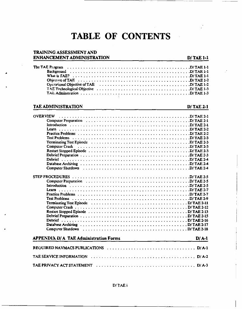
TABLE OF CONTENTS
TRAINING ASSESSMENT ANDENHANCEMENT ADMINISTRATION D/TAE 1-1
The TAE Program .............................................. D/ TAE 1-1Background ............................................. D/ TAE 1-1W hat is FAE? ............................................ D/ TAE 1-1Object ve of TAE ........................................... D/TAE 1-2Operational Objective of TAE .................................. D/ TAE 1-2TAE Technological Objective ................................... D/ TAE 1-3TAL Adminstration ......................................... D/ TAE 1-3
TAE ADMINISTRATION D/ TAE 2-1
OVERVIEW ................................................. D TAE 2-1Computer Preparation ....................................... D/ TAE 2-1Introduction ............................................. D/ TAE 2-1Learn ................................................. D/ TAE 2-2Practice Problems .......................................... D/ TAE 2-2Test Problems ............................................ D/ TAE 2-3Terminating Test Episode .................. .................. D/ TAE 2-3Computer Crash .......................................... D/ TAE 2-3Restart Stopped Episode ...................................... D/ TAE 2-3Debrief Preparation ......................................... D/ TAE 2-3Debrief ................................................ D/ TAE 2-4Database Archiving ......................................... D/ TAE 2-4Computer Shutdown ........................................ D/ TAE 2-4
STEP PROCEDURES ............................................ D/ TAE 2-5Computer Preparation ....................................... D/ TAE 2-5Introduction ............................................. D/ TAE 2-5Learn ................................................. D/ TAE 2-7Practice Problems .......................................... D/ TAE 2-7Test Problems ............................................ D/ TAE 2-9Terminating Test Episode .................................... D/ TAE 2-11Computer Crash .......................................... D/ TAE 2-12Restart Stopped Episode ..................................... D/ TAE 2-13Debrief Preparation ........................................ D/ TAE 2-15Debrief ............................................... DI TAE 2-16Database Archiving ........................................ D/ TAE 2-17Computer Shutdown ....................................... D/ TAE 2-18
APPENDIX D/ A TAE Administration Forms D/A-1
REQUIRED NAVMACS PUBLICATIONS ................................. D/ A-1
TAE SERVICE INFORMATION ....................................... D/ A-2
TAE PRIVACY ACT STATEMENT ..................................... D/ A-3
D/ TAE i
TAE HELP PAPER..................................................... DIA-4
TAE EPISODE TESTING SEQUENCE AND RECORDING.......................... D/ A-5
TAE STUDENT SCORES................................................. D/A-6
TAE CRITIQUE....................................................... D/ A-7
RANKING FACTORS................................................... D/ A-8
SCORED EPISODE..................................................... D/ A-9
SEQUENCE OF EVENTS................................................ D/A-1O
D/ TAE i
TRAINING ASSESSMENT ANDENHANCEMENT ADMINISTRATION
THE TAE PROGRAM
This section provides an introduction to theTroubleshooting Assessment and Enhancement (TAE) T A Eprogram. It describcs the intent of the program, what it istrying to accompi..h, the delivery system, the various trainingtroubleshooting (TS) presentations, how the evaluation/as-sessment scheme is intended to be utilized and how the TAE assessmentTS episodes can b. used for training, assessment and im- andprovement of individual and school performance. enhancement
Background
Currently the Navy is faced with increasing training andoperational costs and declining entry level skills. Resultsfrom other naval studies indicate that the capability of theshipboard technicians and their ability to efficiently and costeffectively maintain combat systems is of great concern.While more complex systems and equipment are increasingmaintenance difficulty, workload, and costs, the personnel T A Eand time available for the training of these personnel in the ADDRESSES THE PROBLEMSmaintenance and improvement of their skills a-e, at best,fixed. Unit and shorebased training costs continue to in- OF TROUBLESHOOTING TRAININGcrease, budgets have shrunk, and the return from a heavy AND ASSESSMENTinvestment in training is being questioned. There was aneed for the design, development, test & evaluation, and im-plementation of a low cost method to optimize school train-ing time and to provide for fleet and reserve readinesscenter development and maintenance of the critical TS skill.
What is TAE?
Sponsored by CNO, TAB is a TS training, assessment,and enhancement system that offers the opportunity for im-proving TS skill development, improvement, and main-tenancc. TAE has total force utility. It was initiatedbecause the Navy has no means of measuring, for diagnos-tic purposes, the troubleshooting proficiency of main-tenance technicians and their ability to accomplish assigned"iS tasks. Other that) subjective supervisory or instructoropinion, there i% no way to objectively and consistently as- IMPROVES TROUBLESHOOTINGsess and diagnoe technician/student performance to im-prove the effects of training in the Navy "C" schools asrelated to remediation of personnel who fall below perfor-mance criteria. Once the "C" school graduate has been in-tegrated into the ships force, fleet commanders have nomethod to maintain the technicians performancecapabilities to obviate skill degradation overtime. In addi-tion, the schools receive no quantifiable feedback identify-ing specific areas where troubleshooting training requiresgreater emphasis or improvement.
D/TAE 1-1
Due to the limited availability of systems hardware at the"C" schools actual hands-on training time is severelyrestricted. This minimizes the amount of time students usetheir system knowledge explicitly and, therefore, decreasesthe effectiveness of instructional programs. Once on-board, the ship safety hazards associated with correctivemaintenance of weapon systems hardware preclude the useof drill and practice exercises. This limits the technicians'ability to maintain their troubleshooting skills and restrictsimprovement of their abilities.
TAE Navy Reserve personnel must receive training to achieve
INCREASES TIME STUDENTS the same level of proficiency as the active forces. In fact,USE SYSTEM KNOWLEDGE given the lessened opportunity for actual hands-on prac-
tice, the amount of reserve training should exceed that ofthe active forces. To achieve these objectives, innovativeuses of limited training resources, particularly time, must beidentified. In addition, there is no way to test and objec-tively assess the transfer of training or performancecapabilities of the reserve personnel. At this time there is noquantifiable way to ensure comparable reserve and activeduty (i.e., total force) personnel in terms of their ability tocontribute to operational readiness.
Objective of TAE
This effort was initiated to develop a microcomputer-based training and assessment system which provides diag-nostic capability for the remediation of personnel failing tomeet criteria established for technical troubleshooting
TAE proficiency. This capability can be used in support of TSskills development, assessment, and maintenance of the
PROVIDES DIAGNOSTIC total forces of the operational and training communities of
CAPABILITY FOR STUDENT the Navy.
REMEDIATIONOperational Objective of TAE
The TAE program supports the operational Navy (totalforces) and the training communities and can, within thehardware systems selected, provide for:
* Assessment of troubleshooting capabilities within theNavy training environment, better use of TechnicalTraining Equipment (TIE) in "C" schools.
" Drill and practice for personnel under trainingawaiting hardware availability or active duty assign-ments (improved utilization of student time, and im-
TAE proved use of TE).
PROVIDES DRILL AND * Curricula and training methods improvement basedPRACTICE TROUBLESHOOTING on feedback of school troubleshooting assessment
results.
" Training through drill and practice exercises.
" Assessment of training effectiveness and retention inthe skill area of troubleshooting proficiency.
DI TAE 1-2
" A diagnostic capability for remediation to improve * Technical information needs in maintenance perfor-TS skills of operational personnel in the area of sys- mance.tems hardware troubleshooting.
" Definition of expert troubleshooting strategies.* Readiness improvement based on diagnostic feed-
back with, and as a result of, diagnostic information * Specifications for job-aiding software.being provided to appropriate offices.
* On-the-job (fleet) training delivery techniques." Improvement of curricula and instructional methods
as a result of diagnostic feedback to the training com- * Use of troubleshooting analysis data in current In-munity. structional System Development.
* A TAE troubleshooting episode development * Relationships between current pedagogical ap-process. proaches and performance results.
* Development and acquisition of troubleshootingTAE Technological Objective aids/trainers and devices, General Purpose
Electronic Test Equipment (GPETE) and specialThe TAE includes advances in the technology of assess- purpose test equipment.
ment of higher order conceptual skills (i.e., problem solv-ing/troubleshooting,) which can in turn provide for Development of generic troubleshooting/problemmodeling of maintenance performance. Definition of the solving model(s).factors that can be used for diagnostic purposes to indicateand remediate personnel for successful maintenance per-formance which provides for a point of departure in the TAE Administrationdevelopment of a systematic research, development, testand evaluation effort. The objective of this effort is to en- The following pages provide information on how to ad-sure that training and aiding will be responsive to operation- minister the TAE program. The procedures have beenal requirements of the active and reserve naval forces developed in a Job Performance Aid (JPA) format so that(current and projected) and will improve the ability of the individual pages can be used, extracted, or copied inmaintenance personnel in the area of maintenance readi- whatever way the administrator feels is most effective.ness. The result of this effort will provide input to or ad-dress issues such as:
TAEWILL IMPROVE THE ABILITY OFMAINTENANCE PERSONNEL IN THEACTIVE AND RESERVE NAVAL FORCES
DI TAE 1-3
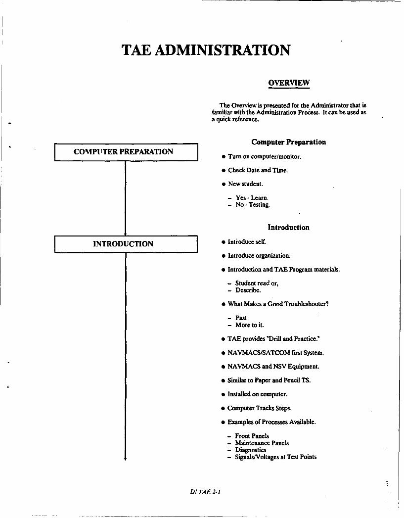
TAE ADMINISTRATION
OVERVIEW
The Overview is presented for the Administrator that isfamiliar with the Administration Process. It can be used asa quick reference.
Computer PreparationCOMPUTER PREPARATION " Turn on computer/monitor.
" Check Date and Time.
* New student.
- Yes - Learn.- No - Testing.
Introduction
[INTRODUCTION * Introduce self.
" Introduce organization.
" Introduction and TAE Program materials.
- Student read or,- Describe.
" What Makes a Good Troubleshooter?
- Past- More to it.
" TAE provides "Drill and Practice."
" NAVMACS/SATCOM first System.
" NAVMACS and NSV Equipment.
" Similar to Paper and Pencil TS.
" Installed on computer.
" Computer Tracks Steps.
" Examples of Processes Available.
- Front Panels- Maintenance Panels- Diagnostics- Signals/Voltages at Test Points
DITAE 2-1
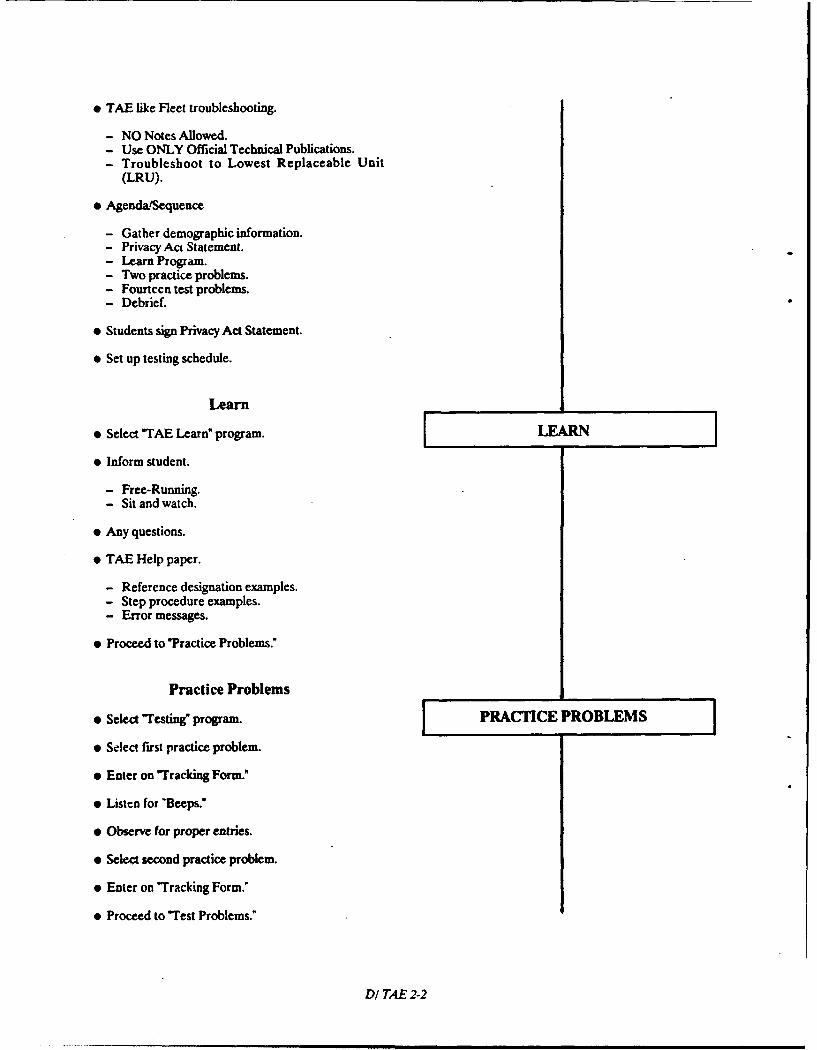
" TAE like Fleet troubleshooting.
- NO Notes Allowed.- Use ONLY Official Technical Publications.- Troubleshoot to Lowest Replaceable Unit
(LRU).
* Agenda/Sequence
- Gather demographic information.- Privacy Act Statement.- Learn Program.- Two practice problems.- Fourteen test problems.- Debrief.
" Students sign Privacy Act Statement.
" Set up testing schedule.
Learn
" Select "TAE Learn" program. LEARN
" Inform student.
- Free-Running.- Sit and watch.
* Any questions.
* TAE Help paper.
- Reference designation examples.- Step procedure examples.- Error messages.
* Proceed to "Practice Problems."
Practice Problems
@ Select "Testing" program. PRACTICE PROBLEMS
" Select first practice problem.
" Enter on "Tracking Form."
* Listen for "Beeps."
" Observe for proper entries.
" Select second practice problem.
" Enter on "Tracking Form."
" Proceed to "Test Problems."
DI TAE 2-2
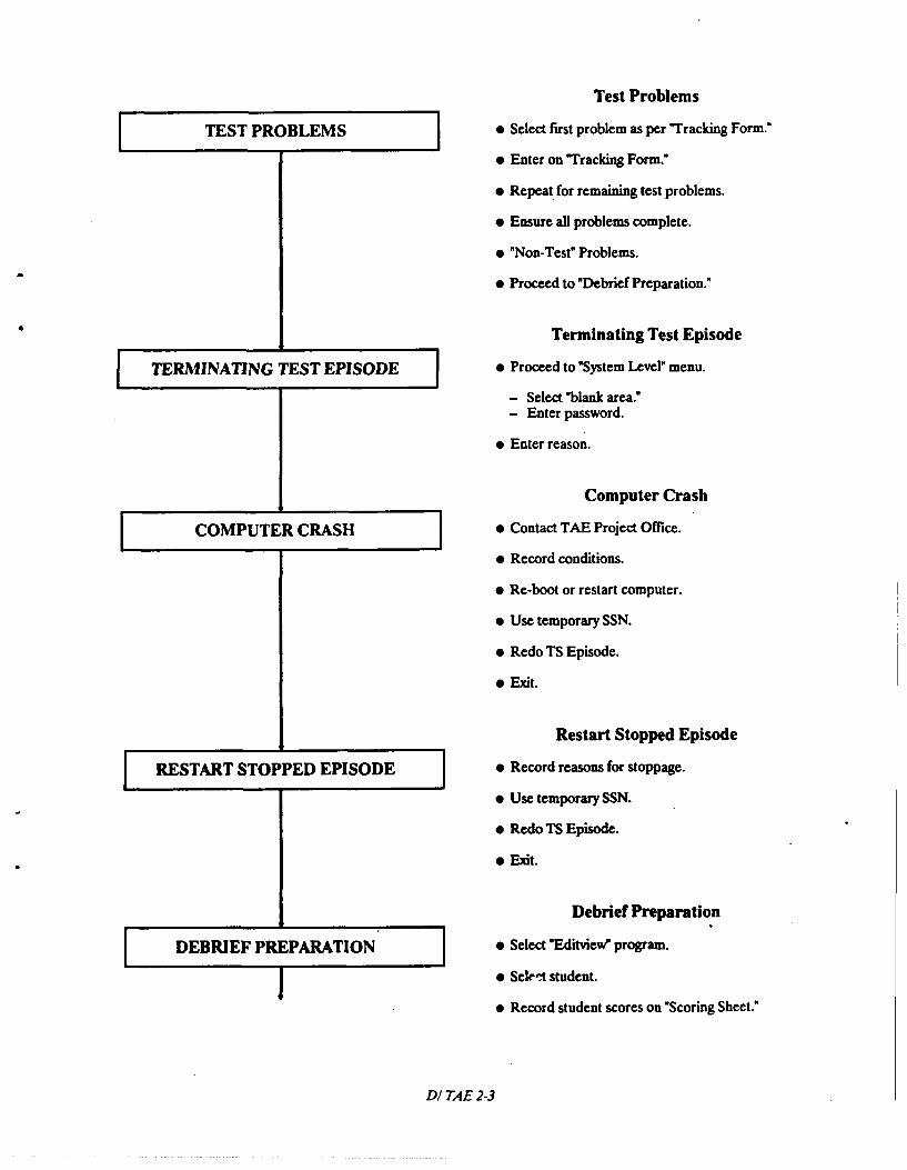
Test Problems
TEST PROBLEMS [ Select first problem as per "Tracking Form."
* Enter on "Tracking Form."
e Repeat for remaining test problems.
* Ensure all problems complete.
* "Non-Test" Problems.
9 Proceed to "Debrief Preparation."
Terminating Test Episode
TERMINATING TEST EPISODE * Proceed to "System Level" menu.
- Select "blank area."- Enter password.
* Enter reason.
Computer Crash
COMPUTER CRASH * Contact TAE Project Office.
* Record conditions.
* Re-boot or restart computer.
* Use temporary SSN.
* Redo TS Episode.
o Exit.
Restart Stopped Episode
RESTART STOPPED EPISODE o Record reasons for stoppage.
o Use temporary SSN.
o Redo TS Episode.
o Exit.
Debrief Preparation
DEBRIEF PREPARATION o Select "Editview" program.
o Sel-t student.
o Record student scores on "Scoring Sheet."
DI TAE 2-3
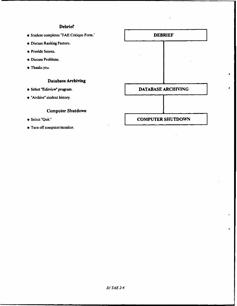
Debrief
" Student completes -TAE Critique Form." DEBRIEF
" Discuss Ranking Factors.
" Provide Scores.
" Discuss Problems.
" Thanks you.
Database Archiving
" Select "EdiMvcw program. [ DATABASE ARCHIVING
" "Archive" student history.
Computer Shutdown
" Select "Quit." [ COMPUTER SHUTDOWN
" Turn off computer/monitor.
DI TAE 2-4
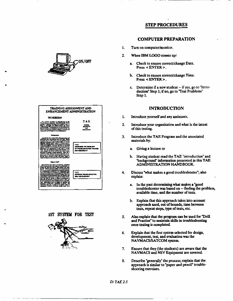
STEP PROCEDURES
COMPUTER PREPARATION
1. Turn on computer/monitor.
2. When IBM LOGO comes up.
N/FF a. Check to ensure correct/change Date.Press <ENTER>.
b. Check to ensure correct/change Time.Press <ENTER>.
c. Determine if a new student -- if yes, go to "Intro-duction" Step 1; if no, go to "Test Problems"Step 1.
TRAINING ASSESSMENT A" INTRODUCTIONENHANCEMENT ADMINISTRATION
1. Introduce yourself and any assistants.,n.. -'- " - . TA E
2. Introduce your organization and what is the intentof this testing.
3. Introduce the TAE Program and the associatedmaterials by:.
- -im - -~~tt ah. fh,.tm aameI Yt.ay
OF MO M-,,M, a. Givi a lecture or
b. Having student read the TAE "introduction" and"background" information presented in this TAEADMINISTRATION HANDBOOK
T11 4 Discuss "htmakes a oo trubuleshot";aJlso
explain:
a. In the past determining what makes a "goodtroubleshooter was based on -- finding the problem,available time, and the number of tests.
b. Explain that this approach takes into accountapproach used, out of bounds, time betweentests, repeat steps, type of tests, etc.
1ST SYSTEM FOR TEST 5. Also explain that the program can be used for *Drill
and Practice" to maintain skills in troubleshootingonce testing is completed.
6. Explain that the first system selected for design,development, test, and evaluation was theNAVMACS/SATCOM system.
7. Ensure that they (the students) are aware that theNAVMACS and NSV Equipment are covered.
8. Describe "generally" the process; explain that theapproach is similar to "paper and pencil" trouble-shooting exercises.
DI TAE 2-5
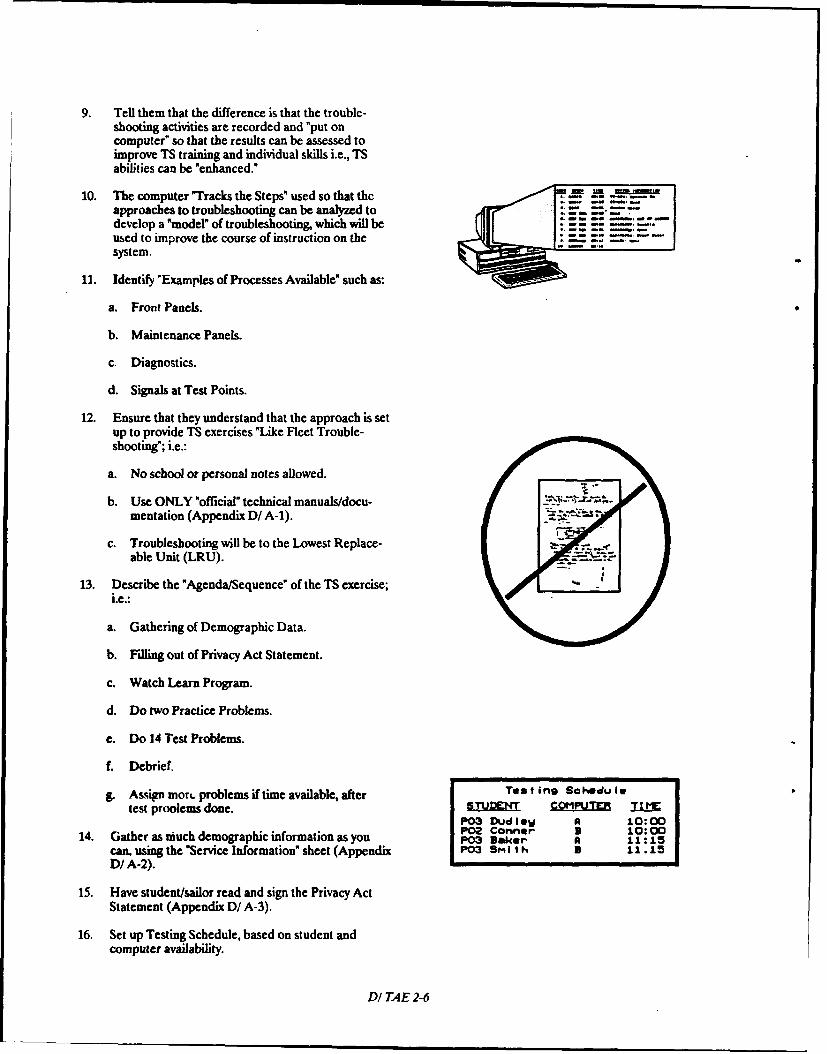
9. Tell them that the difference is that the trouble-shooting activities are recorded and "put oncomputer" so that the results can be assessed toimprove TS training and individual skills i.e., TSabilities can be "enhanced."
10. The computer "Tracks the Steps" used so that theapproaches to troubleshooting can be analyzed todevelop a "model" of troubleshooting, which will beused to improve the course of instruction on thesystem.
11. Identify "Examples of Processes Available' such as:
a. Front Panels.
b. Maintenance Panels.
c. Diagnostics.
d. Signals at Test Points.
12. Ensure that they understand that the approach is setup to provide TS exercises "Like Fleet Trouble-shooting"; i.e.:
a. No school or personal notes allowed.
b. Use ONLY "official" technical manuals/docu-mentation (Appendix D/ A-i).
c. Troubleshooting will be to the Lowest Replace-able Unit (LRU).
13. Describe the "Agenda/Sequence" of the TS exercise;i.e.:
a. Gathering of Demographic Data.
b. Filling out of Privacy Act Statement.
c. Watch Learn Program.
d. Do two Practice Problems.
e. Do 14 Test Problems.
f. Debrief.
g. Assign mort. problems if time available, after Ten tino Sce~-du Ietest proolems done. STUENT C E R T1
P03 Dudlew A 10:00P02 Conner U 10:0014. Gather as much demographic information as you P03 Bake,- a 1: 15
can. using the "Service Information" sheet (Appendix P03 SM I t h 3 11 .15D/ A-2).
15. Have student/sailor read and sign the Privacy ActStatement (Appendix D/A-3).
16. Set up Testing Schedule, based on student andcomputer availability.
DI TAE 2-6
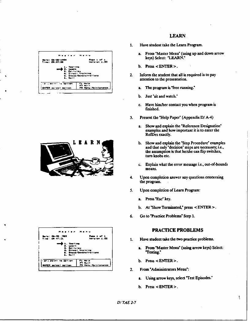
LEARN
1. Have student take the Learn Program.
...... r •.* -a. From "Master Menu" (using up and down arrow
Dole: C11-1149 Pao* L of I keys) Select: "LEARN."
I... 'e Ino b. Press<ENTER>.43. DlC! Tralinil
.I rI- .... ni.. 2. Inform the student that all is required is to pay,. ,, attention to the presentation.
v_ .0 -g, I. i -. - ,.,nan.... a. The program is "free running."
b. Just "sit and watch."
c. Have him/her contact you when program isfinished.
3. Present the "Help Paper" (Appendix D/ A-4)
a. Show and explain the "Reference Designation"examples and how important it is to enter theRefDes exactly.
Lb. Show and explain the "Step Procedure" examplesand that only "decision" steps are necessary, i.e.,the assumption is that he/she can flip switches,turn knobs etc.
c. Explain what the error message i.e., out-of-boundsmeans.
4. Upon completion answer any questions concerning
the program.
5. Upon completion of Learn Program:
a. Press "Esc" key.
b. At "Show Terminated," press <ENTER>.
6. Go to "Practice Problems" Step 1.
,lo tr. men., PRACTICE PROBLEMS3.4o: ai.- :9I09 Pa.. i o' I
,, 41s onui1 ., 1. Have student take the two practice problems.S41. ToI In
3. Cil,,,,.., a. From "Master Menu" (using arrow keys) Select:4. Diet Tralning.o .8",rimno trot ion. "Testing."
'. a it
o nt Me-l I I. °- b. Press <ENTER>.
2. From "Administrators Menu":
a. Using arrow keys, select "Test Episodes."
b. Press <ENTER>.
DI TAE 2-7
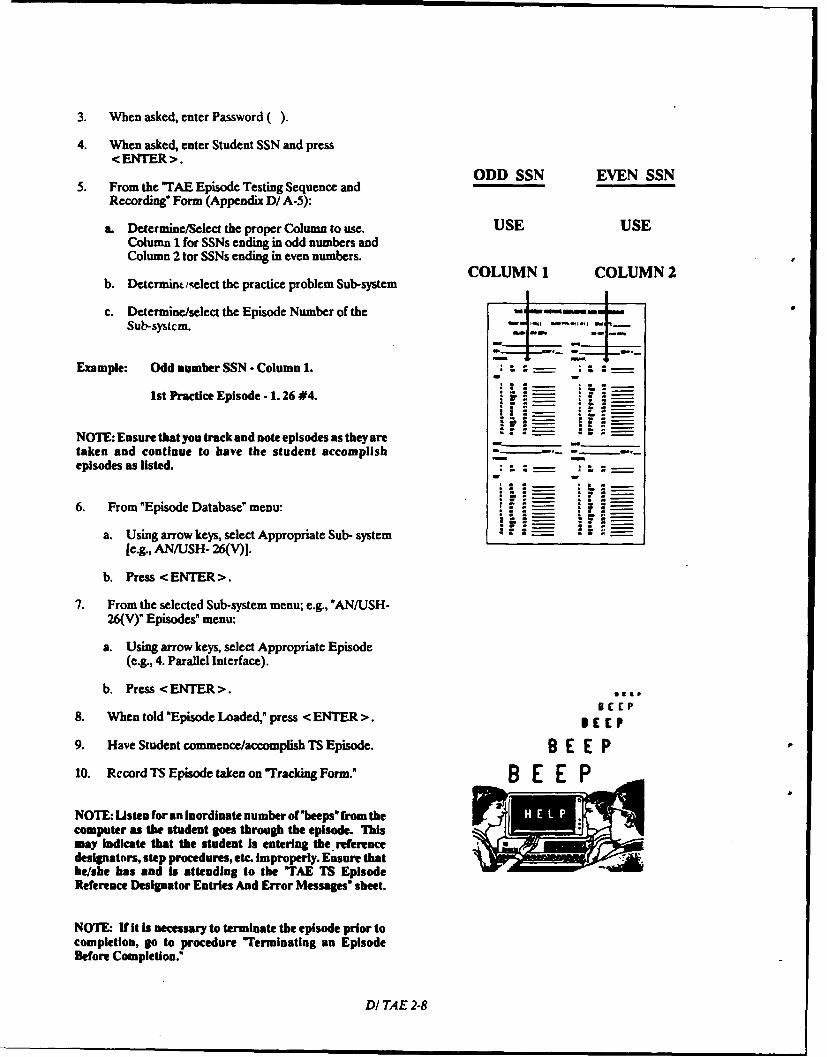
3. When asked, enter Password ().
4. When asked, enter Student SSN and press<ENTER>.
ODD SSN EVEN SSN5. From the "TAE Episode Testing Sequence and
Recording" Form (Appendix D/ A-5):
a. Determine/Select the proper Column to use. USE USEColumn 1 for SSNs ending in odd numbers andColumn 2 tor SSNs ending in even numbers.
COLUMN 1 COLUMN 2b. Determint/gelect the practice problem Sub-system
c. Determine/select the Episode Number of the = -wSub-systcm.
Example: Odd number SSN - Column 1. - -- : L =
1st Practice Episode - 1. 26 #4. !.
NOTE: Ensure that you track and note episodes as they are _
taken and continue to have the student accomplish . . . .episodes as listed. L - S- .- -
6. From "Episode Database" menu: a- 564=
a. Using arrow keys, select Appropriate Sub- system a
[e.g., AN/USH- 26(V)].
b. Press < ENTER >.
7. From the selected Sub-system menu; e.g., "AN/USH-26(V)" Episodes" menu:
a. Using arrow keys, select Appropriate Episode(e.g., 4. Parallel Interface).
b. Press <ENTER>. o3,eC£P
8. When told "Episode Loaded," press <ENTER>. B E p9. Have Student commence/accomplish TS Episode. B E E P10. Record TS Episode taken on "Tracking Form." MO E E
NOTE: Listen for an Inordinate number of'beeps" from thecomputer as the student goes through the episode. Thismay Indicate that the student is entering the referencedesignators, step procedures, etc. improperly. Ensure thatbe/she has and Is attending to the "TAE TS EpisodeReference Designator Entries And Error Messages" sheet.
NOTE- If it is necessary to terminate the episode prior tocompletion, go to procedure "Terminating an EpisodeBefore Completion."
DI TAE 2-8
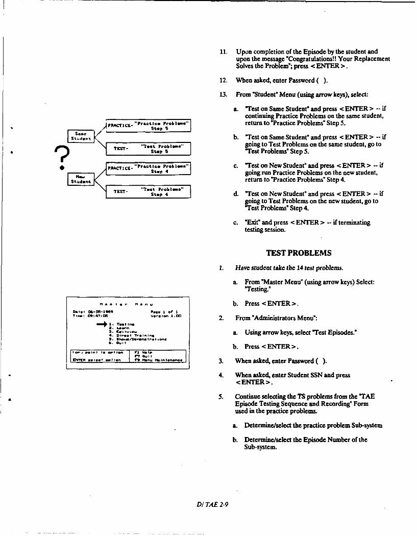
11. Upon completion of the Episode by the student andupon the message "Congratulations!! Your ReplacementSolves the Problem"; press < ENTER >.
12. When asked, enter Password ( ).
13. From "Student" Menu (using arrow keys), select:
a. "Test on Same Student" and press < ENTER > -- ifcontinuing Practice Problems on the same student,
PRACrICE-". Practice Problims" return to "Practice Problems" Step 5.Step s
SoeIStudent b. "Test on Same Student" and press < ENTER > -- if
S"Test Proble" going to Test Problems on the same student, go tosTEST Step s 'Test Problems" Step 5.
*PACTICE- "Pracice Problems c. "Test on New Student" and press < ENTER > -- ifumStop 4 going run Practice Problems on the new student,
[Toot return to "Practice Problems" Step 4.S TEST- "TSt. rob i s" I
step 4 d. "Test on New Student" and press < ENTER > -- ifgoing to Test Problems on the new student, go to"Test Problems" Step 4.
c. "Exit" and press < ENTER > -- if terminatingtesting session.
TEST PROBLEMS
1. Have student take the 14 test problems.
a. From "Master Menu" (using arrow keys) Select:"Testing."
-- , -- b. Press<ENTER>.Date: O-0-19S9 PaO I of IT,,...: o9:47:o5 ue.Ion 1.00 2. From "Administrators Menu":
"41. Taile2.Lee,-
4. Diret Taining a. Using arrow keys, select "Test Episodes."4. C. D e.nefToton.
,. o ,,b. Press < ENTER >.
Ir? QvitENTER 00100o' optioen 70 MPW IlInte~nee 3. When asked, enter Password ()
4. When asked, enter Student SSN and press<ENTER>.
5. Continue selecting the TS problems from the "TAEEpisode Testing Sequence and Recording" Formused in the practice problems.
a. Determine/select the practice problem Sub-system
b. Determine/select the Episode Number of theSub-system.
DI TAE 2-9
Example: Even number SSN - Column 2.1st Test Episode - 1.20 #3.
NOTE: Ensure thatyou trackand note episodes as they aretaken and continue to have the student accomplishepisodes as listed. Once all the "Test And Evaluation"episodes have been completed, you may present theremainder in any sequence/number you wish. SdMt ilSb-System
6. From "Episode Database" menu: AN/USH-26(V)
a. Using arrow keys, select Appropriate Sub- system AN/USQ-69(V)le.g., ANIUYK-20(V)].
b. Press < NTER>. AN/UYK-20(V)
7. From the selected Sub-system menu; e.g., "AN/UYK- CV-=3/U20(V)" Episodes" menu:
a. Using arrow keys, select Appropriate Episode 0N-143(V)/USQ(e.g., 3. Channel 14 Interface). RD-397(V)/U
b. Press <ENTER>.
8. When told "Episode Loaded," press < ENTER >. T-624(V)UG
9. Have Student Commence/accomplish TS Episode.
10. Record TS Episode taken on "Tracking Form."
NOTE: Listen for an inordinate number of"beeps" from thecomputer as the student goes through the episode. Thismay indicate that the student Is entering the referencedesignators, step procedures, etc. Improperly. Ensure thathe/she has and is attending to the "TAE TS EpisodeReference Designator Entries And Error Messages" sheet.
NOTE: If it is necessary to terminate the episode prior tocompletion, go to procedure "Terminating an EpisodeBefore Completion."*~
11. Upon completion of the Episode by the student andupon the message "Congratulations!! Your ReplacementSolves the Problem," press <ENTER>.
12. When asked, enter Password ( ).
13. From "Student" Menu (using arrow keys), select:
a. "Test on Same Student" and press <ENTER > -- ifcontinuing Test Problems on the same student,return to "Test Problems' Step 5.
b. "Test on New Student" and press < ENTER > -- ifgoing run Practice Problems on the new student,go to "Practice Problems Step 4.
D/ TAE 2-10
c. "Test on New Student" and press < ENTER > -- ifgoing to Test Problems on the new student, go to"Test Problems" Step 4.
d. "Exit" and press < ENTER > -- if terminatingtesting session.
TERMINATING TEST EPISODE
The following steps are to be used, if a need arises, toEND a TS Episode before the student is done.
1. Return to "System Level" Menu. Use following
Terminale procedure until the "System Level" Menu is reached.
An Episode a. Using arrow keys, select Return.
b. Press <ENTER>.Before
2. From "System Level" Menu.Completiona. Using arrow keys, select the "blank area under
Replace LRU."
b. Press < ENTER >.
3. When asked, enter Password ().
4. ENTER the reason for the termination of the episode[and who okayed it.
a. TYPE your initials, a blank space, and short reasonfor termination.
For b. Press <ENTER>.
Sickness, Example: DED Go to Dental.
P T,5. From "Student" Menu (using arrow keys), select:
Etc.a. "Test on Same Student" and press < ENTER > -- if
continuing Test Problems on the same student,return to "Test Problems" Step 5.
b. "Test on New Student" and press < ENTER > -- ifgoing run Practice Problems on the new student,go to "Practice Problems" Step 4.
c. "Test on New Student" and press < ENTER > -- ifgoing to Test Problems on the new student, go to"Test Problems" Step 4.
d. "Exit" and press < ENTER > -- if terminatingtesting session.
DI TAE 2-11
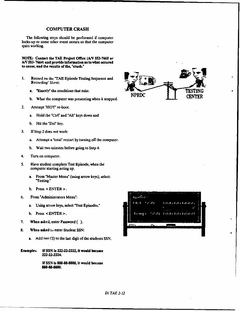
COMPUTER CRASH
The following steps should be performed if computerlocks-up or some other event occurs so that the computerquits working.
NOTE: Contact the TAE Project Office (A/V 553-7665 orA/V 553- 7664) and provide Information as to what occuredto cause, and the results of the, "crash."
1. Record on the "TAE Episode Testing Sequence and
Recording ' Sheet:
a. "Exactly" the conditions that exist. - TE INGNPRIC1-b. What the computer was presenting when it stopped. CENTR
2. Attempt "HOT re-boot.
a. Hold the "Ctrl" and "Alt" keys down and
b. Hit the "Del" key.
3. If Step 2 does not work:
a. Attempt a "total" restart by turning off the computer.
b. Wait two minutes before going to Step 4.
4. Turn on computer.
5. Have student complete Test Episode, when thecomputer starting acting up.
a. From "Master Menu" (using arrow keys), select:"Testing."
b. Press <ENTER>.
6. From "Administrators Menu":
a. Using arrow keys, select wTest Episodes."
b. Press < ENTER>.
7. When asked, enter Password ().
8. When asked to enter Student SSN:
a. Add two (2) to the last digit of the students SSN.
Examples. If SSN Is 222-22-2222, it would become222-22-2224.
If SSN is 888-88-8888, It would become88848-E20.
DI/TAE 2-12
b. Type in this new temporary SSN.
c. Press <ENTER>.
9. From "Episode Database" menu:
a. Using arrow keys, select Appropriate Sub- systemto redo.
b. Press < ENTER >.
SELECT SAME 10. From the selected Sub-system menu" Episodes" menu:
a. Using arrow keys, select Appropriate Episode toSUB-SYSTEM redo.
AND EPISODE b. Press <ENTER>.
11. When told "Episode Loaded," press < ENTER >.
12. Have Student Commence/Accomplish TS Episode,when the computer starts acting up.
13. Upon completion of THIS Episode by the student andupon the message "Congratulations!! Your ReplacementSolves the Problem," Press < ENTER >.
14. When asked, enter Password ().
15. From "Student" Menu (using arrow keys), select:
a. 'Test on New Student" and press < ENTER > -- ifgoing to Test Problems on the SAME student, goto "Test Problems" Step 4 and enter correct SSN.
S&me TET "Teat Problem."SSd Step 4 b. "Test on New Student" and press < ENTER > -- if
going to Test Problems on the new student, go toT "Test Probl." c "Test Problems" Step 4.
Student c. "Test on New Student" and press < ENTER > -- ifX I -"rctice Probm" going to run Practice Problems on the new student,
Stop 4 go to "Practice Problems" Step 4.
d. "Exit" and press < ENTER > -- if terminatingtesting session.
RESTARTING STOPPED EPISODE
The following steps should be performed if a studentneeds to be restarted on a IS Episode that needed to bestopped for whatever reason.
1. Record on the "TAE Episode Testing Sequence andRecording" Sheet the reason for the stoppage.
2. Have student complete the Test Episode that wasstopped.
a. From "Master Menu" (using arrow keys) Select:"Testing."
DI TAE 2-13
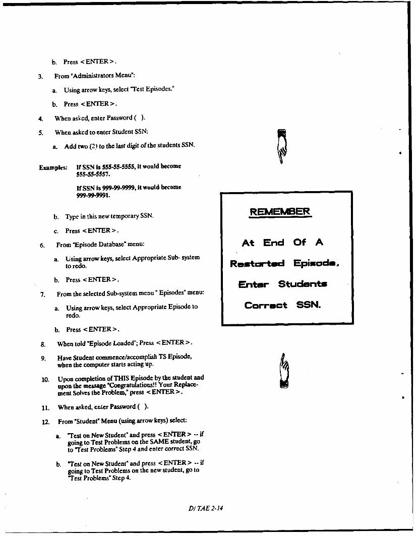
b. Press < ENTER >.
3. From "Administrators Menu":
a. Using arrow keys, select "Test Episodes."
b. Press <ENTER>.
4. When askcd, enter Password ().
S. When askcd to enter Student SSN:
a. Add two (2) to the last digit of the students SSN.
Examples: If SSN is 555.55-5555, it would become555.55-5557.
If SSN is 999-99-9999, it would become999-99-9991.
b. Type in this new temporary SSN. REMEMBER
c. Press <ENTER>.
6. From "Episode Database" menu: At End Of A
a. Using arrow keys, select Appropriate Sub- systemto redo. Restarted Episode,
b. Press <ENTER>.
7. From the selected Sub-system menu" Episodes" menu:
a. Using arrow keys, select Appropriate Episode to Correct SSN.redo.
b. Press <ENTER>.
8. When told "Episode Loaded"; Press < ENTER >.
9. Have Student commence/accomplish TS Episode,when the computer starts acting up.
10. Upon completion of THIS Episode by the student andupon the message "Congratulations!! Your Replace-ment Solves the Problem," press < ENTER >.
11. When asked, enter Password ().
12. From "Student" Menu (using arrow keys) select:
a. 'Test on New Student" and press < ENTER > -- ifgoing to Test Problems on the SAME student, goto wTest Problems" Step 4 and enter correct SSN.
b. "Test on New Student" and press < ENTER > -- ifgoing to Test Problems on the new student, go to"Test Problems" Step 4.
DI TAE 2-14
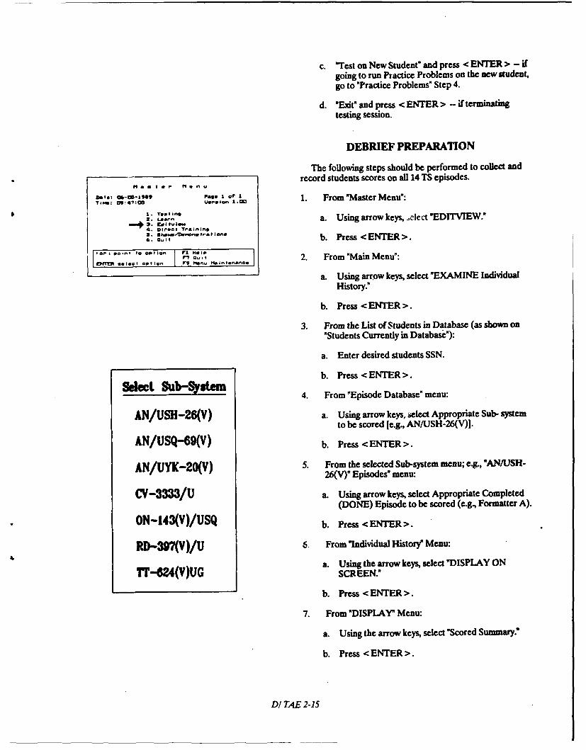
c. "Test on New Student" and press < ENTER > - ifgoing to run Practice Problems on the new student,go to "Practice Problems" Step 4.
d. "Exit" and press < ENTER > -- if terminatingtesting session.
DEBRIEF PREPARATION
The following steps should be performed to collect andrecord students scores on all 14 TS episodes.
Date C* -10 Pag a of I'
DT,: C-" ! 9,I ,.. 1 .0 1. From 'Master Menu':
0 1 . Testins2. ,-. a. Using arrow keys, oelect "EDITVIEW."4 Direct T &ining
.I, b. Press <ENTER>.
,0 PcI,.* 90 O n 7 2. From"Main Menu:DEN lect option 7g p"n. Maintenanoe
a. Using arrow keys, select "EXAMINE IndividualHistory."
b. Press <ENTER>.
3. From the List of Students in Database (as shown on"Students Currently in Database"):
a. Enter desired students SSN.
b. Press <ENTER>.Sdeet saL qy n 4. From "Episode Database" menu:
AN/USH-26(V) a. Using arrow keys, select Appropriate Sub- systemto be scored [e.g., AN/USH-26(V)].
AN/USQ-69(V) b. Press <ENTER>.
AN/UYK-20(V) 5. From the selected Sub-system menu; e., "AN/USH-26(V)" Episodes" menu:
CV-33 /U a. Using arrow keys, select Appropriate Completed(DONE) Episode to be scored (e.g., Formatter A).
ON-143(V)/USQ b. Press <ENTER>.
RD-397(V )/U 6. From "Individual History' Menu:
a. Using the arrow keys, select "DISPLAY ON7T-M2(V)UG SCREEN.'
b. Press <ENTER>.
7. From "DISPLAY" Menu:
a. Using the arrow keys, select "Scored Summary:
b. Press <ENTER>.
DI TAE 2-15
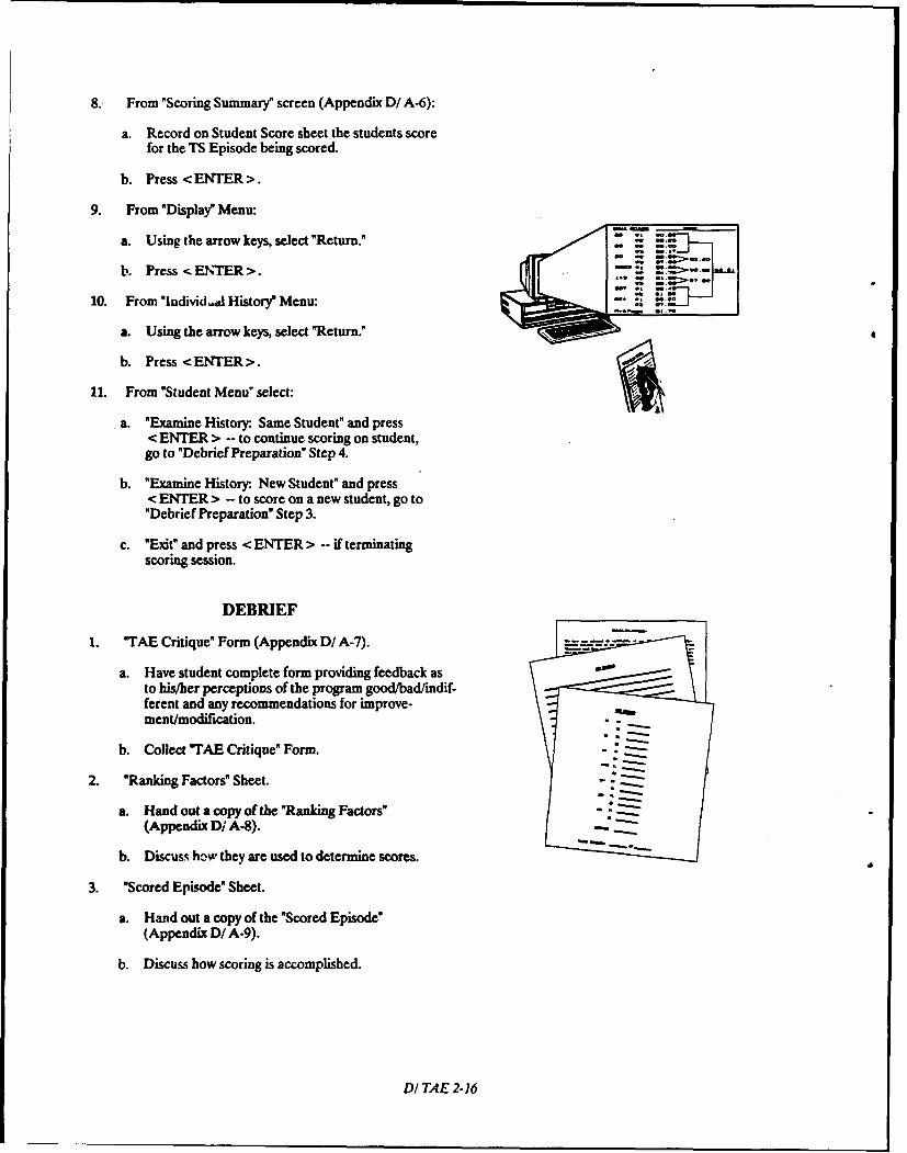
8. From "Scoring Summary" screen (Appendix D/ A-6):
a. Record on Student Score sheet the students scorefor the TS Episode being scored.
b. Press <ENTER>.
9. From "Display" Menu:
a. Using the arrow keys, select "Return." Z ::
b. Press < ENT1 ER >. " :
10. From "Individal History" Menu: -'
a. Using the arrow keys, select "Return."
b. Press <ENTER>.
11. From "Student Menu" select:
a. "Examine History: Same Student" and press< ENTER > -- to continue scoring on student,go to "Debrief Preparation" Step 4.
b. "Examine History: New Student" and press< ENTER > -- to score on a new student, go to"Debrief Preparation" Step 3.
c. "Exit" and press < ENTER > -- if terminatingscoring session.
DEBRIEF
1. "TAE Critique" Form (Appendix D/ A-7). -. .
a. Have student complete form providing feedback as -to his/her perceptions of the program good/bad/indif-ferent and any recommendations for improve-ment/modification.
b. Collect "TAE Critique" Form.
2. "Ranking Factors" Sheet.
a. Hand out a copy of the "Ranking Factors"(Appendix D/ A-8).
b. Discuss how they are used to determine scores.
3. "Scored Episode" Sheet.
a. Hand out a copy of the "Scored Episode"(Appendix D/ A-9).
b. Discuss how scoring is accomplished.
DI TAE 2-16
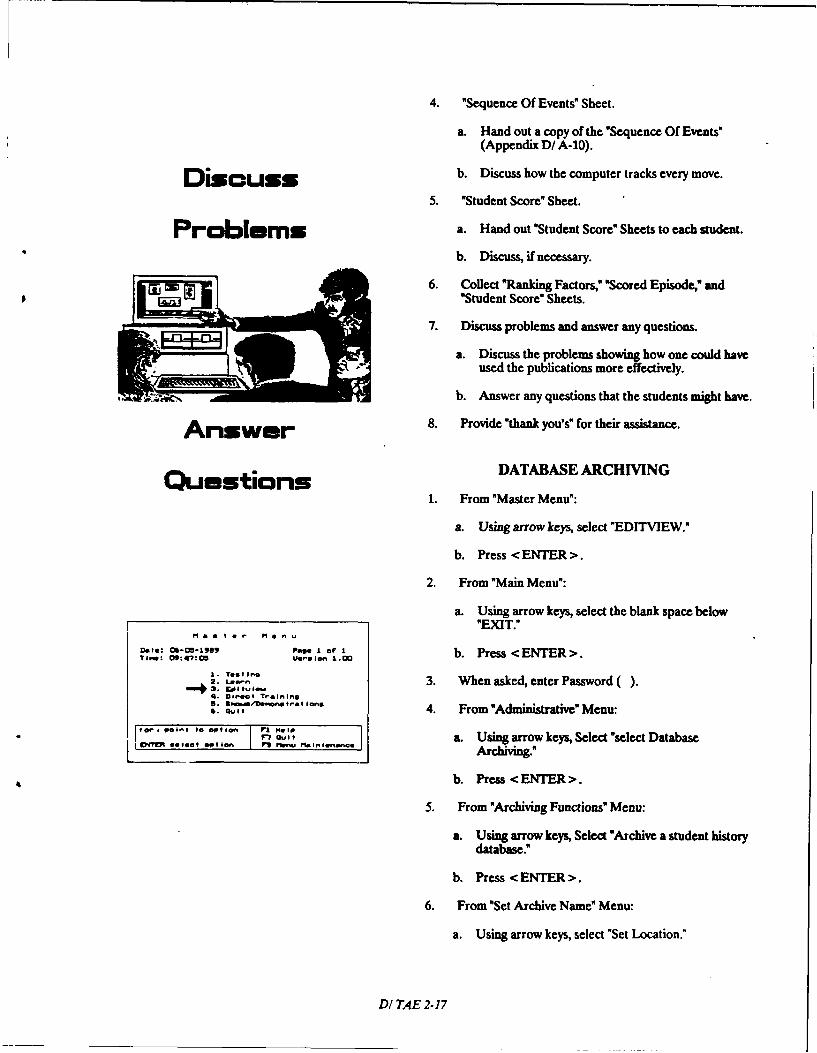
4. "Sequence Of Events" Sheet.
a. Hand out a copy of the "Sequence Of Events"(Appendix D/ A-10).
D iscuss b. Discuss how the computer tracks every move.
5. "Student Score" Sheet.
Problem s a. Hand out "Student Score" Sheets to each student.
b. Discuss, if necessary.
6. Collect "Ranking Factors," "Scored Episode," and* "Student Score" Sheets.
7. Discuss problems and answer any questions.
a. Discuss the problems showing how one could haveused the publications more effectively.
b. Answer any questions that the students might have.
A nsw er 8. Provide "thank you's" for their assistance.
Questions FroDATABASE ARCHIVING
1. From "Master Menu":
a. Using arrow keys, select "EDITVIEW."
b. Press <ENTER>.
2. From "Main Menu":
a. Using arrow keys, select the blank space below"EXIT."
a a t a r Menu
ft..: Ob-CO-47 peg I of I b. Press <ENTER>.71.0: O9: 47: 05 UernI On 1.0
I. Test in.
Le. , 3. wnn ene2 : " ', 3. When asked, enter Password ().4. Direct Training. 3,, 4. From "Administrative" Menu:
r?, t,, a. Using arrow keys, Select "select Databasei IDdT ao get p ion r .fnu Maintenance Archiving."
b. Press <ENTER>.
5. From "Archiving Functions" Menu:
a. Using arrow keys, Select "Archive a student historydatabase."
b. Press < ENTER >.
6. From "Set Archive Name" Menu:
a. Using arrow keys, select "Set Location."
DI TAE 2-17
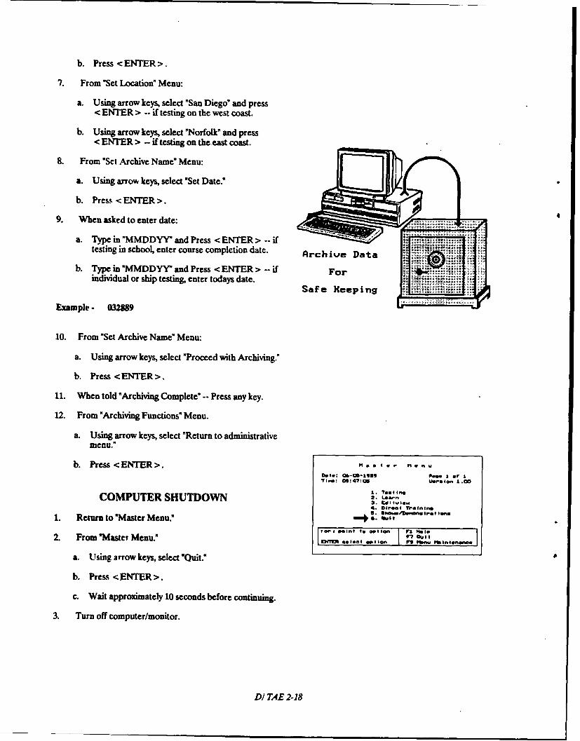
b. Press <ENTER>.
7. From "Set Lo~cation" Menu:
a. Using arrow keys, select 'San Diego" and press< ENTER > -- if testing on the west coast.
b. Using arrow keys, select "Norfolk" and press< ENTER > -- if testing on the east coast.
8. From 'Set Archive NameMenu:
a. Using arrow keys, select "Set Date."
b. Press <ENTER>.
9. When asked to enter date: ....
a. Type in"MMDDYY and Press< ENTER> --iftesting in school, enter course completion date. Archive Data
b. Type in"MMDDYY"and Press <ENTER> --ifindividual or ship testing, enter todays date.
Example - 032389
10. From "Set Archive Name" Menu:
a. Using arrow keys, select "Proceed with Archiving."
b. Press <ENTER>.
11. When told "Archiving Complete" -- Press any key.
12. From "Archiving Functions" Menu.
a. Using arrow keys, select "Return to administrativemenu."
b. Press <ENTER>. ~a re Me0n WDoe: Ci-011-i989 rose I or I
COMPUTER SHUTDOWN 2: Ljean
1. Return to "Master Menu." quit r lft
OepA point Is "llon I elSp
2. From Waster Menu." f7 Oulit
a. Using arrow keys, select "Quit."
b. Press <ENTER>.
c. Wait approximately 10 seconds before continuig
3. Turn off computer/monitor.
DI TAE 2-18
APPENDIX D/ A
T AEADM IN ISTRATION FORMS
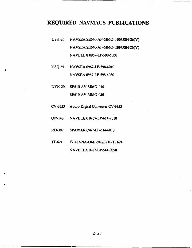
REQUIRED NAVMACS PUBLICATIONS
USH-26 NAVSEA SE640-AF-MMO-010LJSH-26(V)
NAVSEA SE640-AF-MMO-020USH-26(V)
NAVELEX 0967-LP-598-5030
USQ-69 NAVSEA 0967-LP-598-4010
NAVSEA 0967-LP-598-4030
LUYK-20 SE610-AV-MMO-010
SE610-AV-MMO-050
CV-3333 Audio-Digital Converter CV-3333
ON-143 NAVELEX 0967-LP-614-7010
RD-397 SPAWAR 0967-LP-614-6010
T"-624 EE161-NA-OMI-010/E110-TI'624
NAVELEX 0967-LP-544-0050
DIA-1
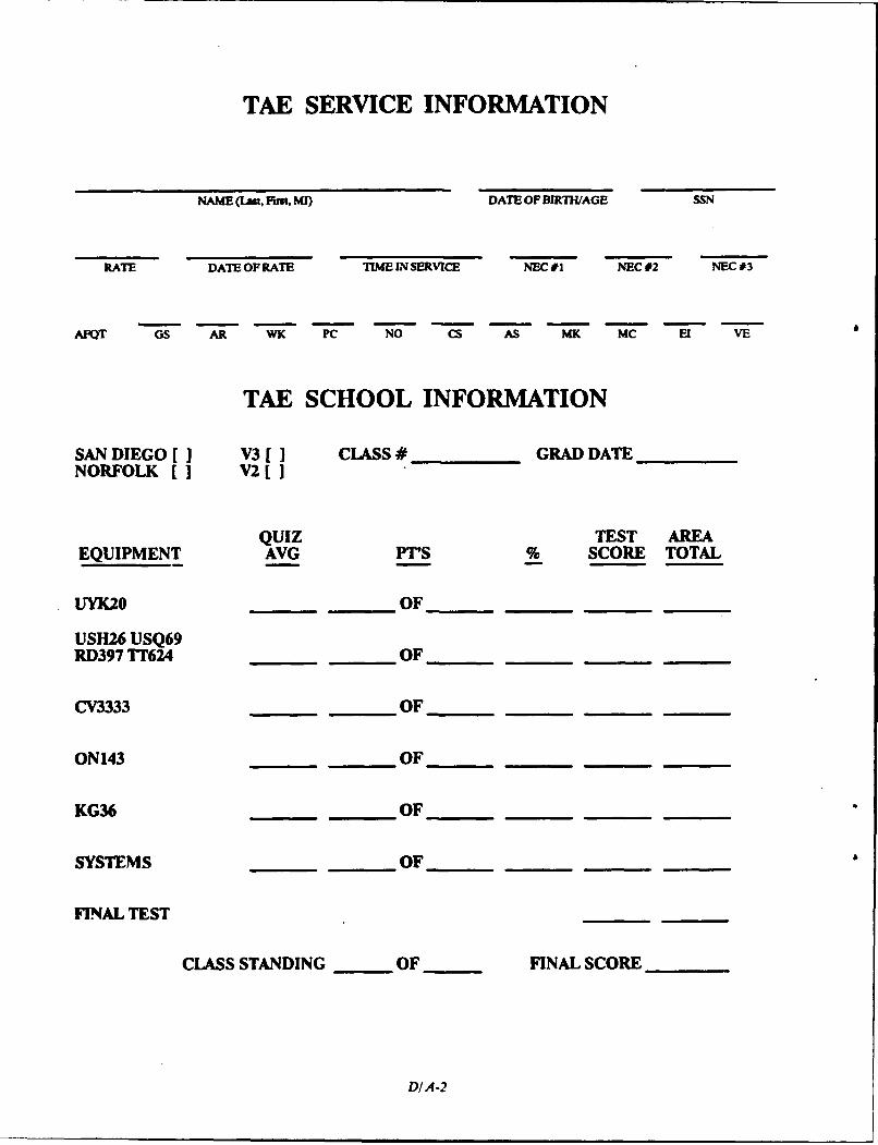
TAE SERVICE INFORMATION
NAME (Las, First, MI) DATE OF BIRTH/AGE SSN
RATE DATE OF RATE TIME IN SERVICE NEC #1 NEC #2 NEC #3
AFOT GS AR WK PC NO CS AS MK MC El VE
TAE SCHOOL INFORMATION
SAN DIEGO [ V3 [1 CLASS # GRAD DATENORFOLK [] V2[ ]
QUIZ TEST AREAEQUIPMENT AVG PT'S % SCORE TOTAL
UYK20 OF
USH26 USQ69RD397 TT624 OF
CV3333 OF
ON143 OF
KG36 OF
SYSTEMS OF
FINAL TEST
CLASS STANDING OF FINAL SCORE
DIA-2
TAE PRIVACY ACT STATEMENT
You have been selected to participate in the TAE project. This project provides research data on thedifferent levels of troubleshooting expertise associated with Navy systems and equipment. The infor-mation provided by you will be used by the Navy Personnel Research and Development Center, SanDiego, for research purposes only. It will not become a part of your official record, nor will it be usedto make decisions about you which will affect your career in any way. Your name, SSN are necessaryonly to aid in processing the research data.
Print Name: SSN:
Signature: Date:
D/A-3
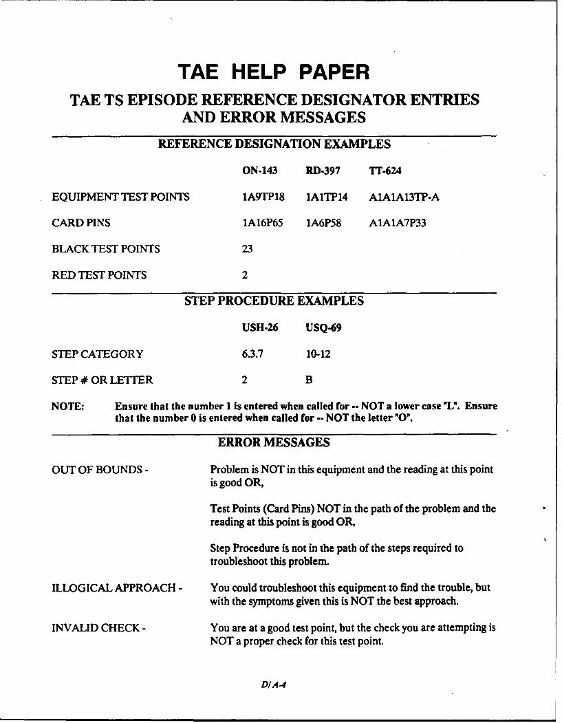
TAE HELP PAPERTAE TS EPISODE REFERENCE DESIGNATOR ENTRIES
AND ERROR MESSAGES
REFERENCE DESIGNATION EXAMPLES
ON-143 RD-397 TT-624
EQUIPMENT TEST POINTS 1A9TP18 1A1TP14 A1A1A13TP-A
CARD PINS 1A16P65 1A6P58 A1A1A7P33
BLACK TEST POINTS 23
RED TEST POINTS 2
STEP PROCEDURE EXAMPLES
USH-26 USQ.69
STEP CATEGORY 6.3.7 10-12
STEP # OR LETTER 2 B
NOTE: Ensure that the number I is entered when called for -- NOT a lower case "L". Ensurethat the number 0 is entered when called for -- NOT the letter "O".
ERROR MESSAGES
OUT OF BOUNDS - Problem is NOT in this equipment and the reading at this pointis good OR,
Test Points (Card Pins) NOT in the path of the problem and thereading at this point is good OR,
Step Procedure is not in the path of the steps required totroubleshoot this problem.
ILLOGICAL APPROACH - You could troubleshoot this equipment to find the trouble, butwith the symptoms given this is NOT the best approach.
INVALID CHECK - You are at a good test point, but the check you are attempting isNOT a proper check for this test point.
DIA-4
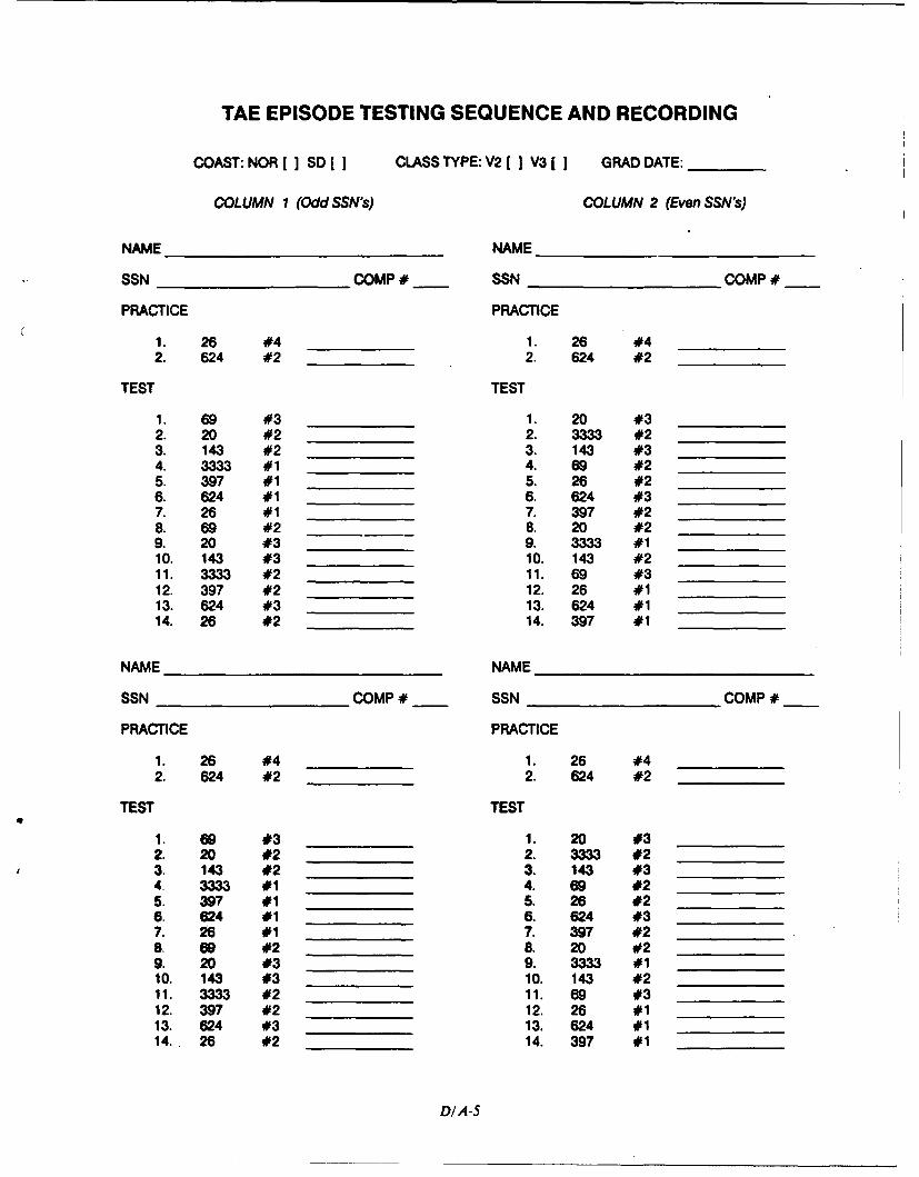
TAE EPISODE TESTING SEQUENCE AND RECORDING
COAST: NOR[ ] SD [ CLASS TYPE: V2 I I V3[ ] GRAD DATE:
COLUMN 1 (Odd SSN's) COLUMN 2 (Even SSN's)
NAME NAME
SSN COMP# SSN COMP#
PRACTICE PRACTICE
1. 26 #4 1. 26 #42. 624 #2 2. 624 #2
TEST TEST
1. 69 #3 1. 20 #32. 20 #2 2. 3333 #23. 143 #2 3. 143 #34. 3333 #1 4. 69 #25. 397 #1 5. 26 #26. 624 #1 6. 624 #37. 26 #1 7. 397 #28. 69 #2 8. 20 #29. 20 #3 9. 3333 #110. 143 #3 10. 143 #211. 3333 #2 11. 69 #312. 397 #2 12. 26 #113. 624 #3 13. 624 #114. 26 #2 14. 397 #1
NAME NAME
SSN COMP # SSN COMP #
PRACTICE PRACTICE
I. 26 #4 1 . 26 #42. 624 #2 2. 624 #2
TEST TEST
1. 69 #3 1 20 #32. 20 #2 2. 3333 #23. 143 #2 3. 143 #34. 3333 #1 4. 69 #25. 397 #1 5. 26 #26. 624 #1 6. 624 #37. 26 #1 7. 397 #28. 69 #2 8 20 #29. 20 #3 9. 3333 #110. 143 #3 10. 143 #211. 3333 #2 11. 69 #312. 397 #2 12. 26 #113. 624 #3 13. 624 #114. 26 #2 14. 397 #1
DIA-5
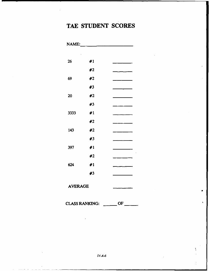
TAE STUDENT SCORES
NAME:_________
26 #1___ __
#2__ _ _
69 #2 _____
#3__ _ _
20 #2__ ___
#3__ _ _
3333 #1__ ___
#2__ _ _
143 #2 __ __
#3__ _ _
397 #1___ __
#2__ _ _
624 #1___ __
#3__ _ _
AVERAGE ___
CLASS RANKING: OF__
DIA-6
TAE CRITIQUE
NAME:________________ DATE:_____(Please Print)
Use other side for additional comments.
DIA .7
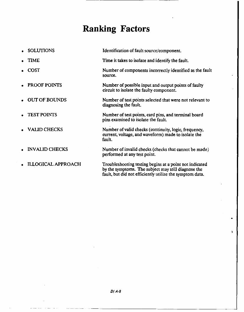
Ranking Factors
* SOLUTIONS Identification of fault source/component.
" TIME Time it takes to isolate and identify the fault.
" COST Number of components incorrectly identified as the faultsource.
" PROOF POINTS Number of possible input and output points of faultycircuit to isolate the faulty component.
" OUT OF BOUNDS Number of test points selected that were not relevant todiagnosing the fault.
" TEST POINTS Number of test points, card pins, and terminal boardpins examined to isolate the fault.
" VALID CHECKS Number of valid checks (continuity, logic, frequency,current, voltage, and waveform) made to isolate thefault.
" INVALID CHECKS Number of invalid checks (checks that cannot be made)performed at any test point.
" ILLOGICAL APPROACH Troubleshooting testing begins at a point not indicatedby the symptoms. The subject may still diagnose thefault, but did not efficiently utilize the symptom data.
D/A-8
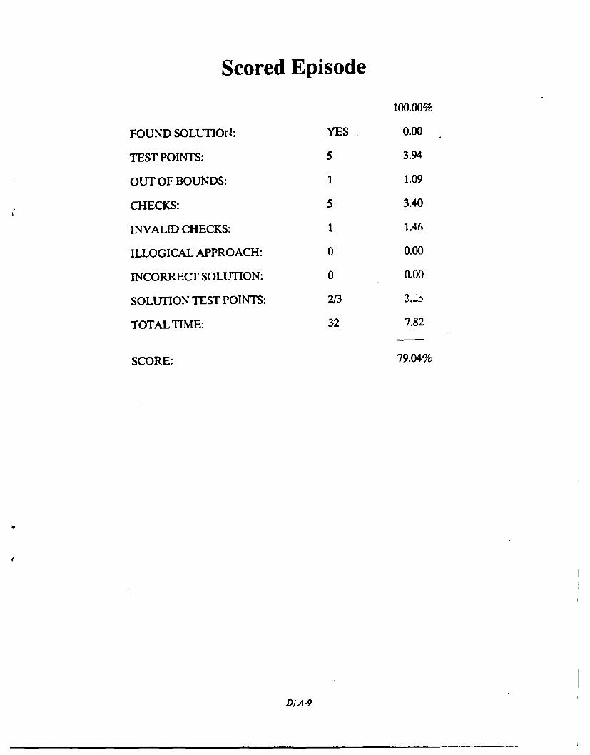
Scored Episode
100.00%
FOUND SOLUTION: YES 0.00
TEST POINTS: 5 3.94
OUT OF BOUNDS: 1 1.09
CHECKS: 5 3.40
INVALID CHECKS: 1 1.46
ILLOGICAL APPROACH: 0 0.00
INCORRECT SOLUTION: 0 0.00
SOLUTION TEST POINTS: 2/3
TOTAL TIME: 32 7.82
SCORE: 79.04%
DIA-9
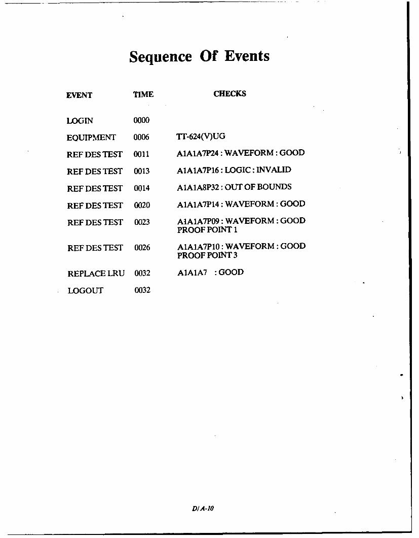
Sequence Of Events
EVENT TIME CHECKS
LOGIN 0000
EQUIPMENT 0006 TT-624(V)UG
REF DES TEST 0011 A1AIA7P24 : WAVEFORM: GOOD
REF DES TEST 0013 A1A1A7P16: LOGIC: INVALID
REF DES TEST 0014 A1AIA8P32: OUT OF BOUNDS
REF DES TEST 0020 A1AlA7P14 : WAVEFORM : GOOD
REF DES TEST 0023 AtAIA7PO9 : WAVEFORM : GOODPROOF POINT 1
REF DES TEST 0026 A1AIA7P1O: WAVEFORM : GOODPROOF POINT 3
REPLACE LRU 0032 A1A1A7 : GOOD
LOGOUT 0032
DIA-1O

DISTRIBUTION LIST
Distribution:Director, Total Force Training and Education (OP-11)Director, Training Technology (Code N-54)Commanding Officer, Naval Education and Training Program Management Support Activity
(Code 03)Chief of Naval Technical Training (Code 00) (2)Commander, Training Command, U.S. Atlantic FleetCommanding Officer, Service School Command, San Diego, CADefense Technical Information Center (2)
Copy to:Commander, Naval Reserve Force, New Orleans, LADepartment of the Air Force, DET 5, Armstrong Laboratory Directorate, Brooks Air Force Base,
IxCommander, U.S. ARI, Behavioral and Social Sciences, Alexandria, VA (PERI-POT-I)Superintendent, Naval Postgraduate SchoolCenter for Naval Analyses