Embed Size (px)
Citation preview
Cisco IOS XR Troubleshooting Guide fOL-23591-02
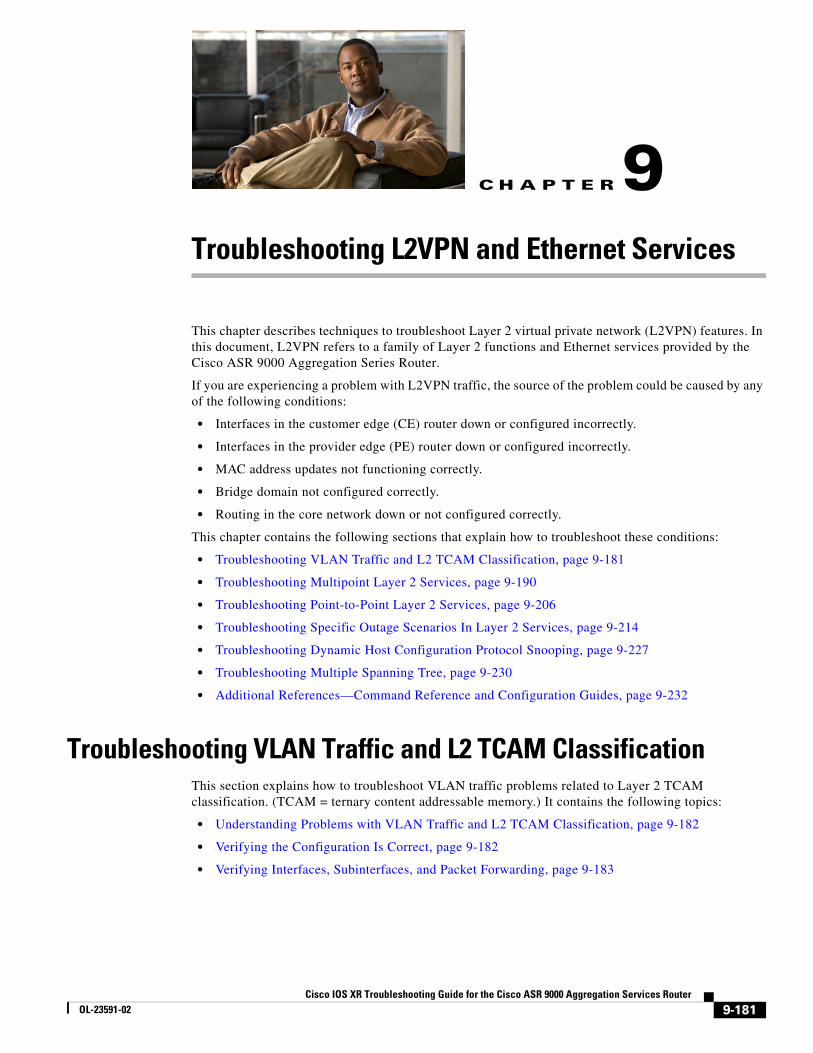
C H A P T E R 9
Troubleshooting L2VPN and Ethernet ServicesThis chapter describes techniques to troubleshoot Layer 2 virtual private network (L2VPN) features. In this document, L2VPN refers to a family of Layer 2 functions and Ethernet services provided by the Cisco ASR 9000 Aggregation Series Router.
If you are experiencing a problem with L2VPN traffic, the source of the problem could be caused by any of the following conditions:
• Interfaces in the customer edge (CE) router down or configured incorrectly.
• Interfaces in the provider edge (PE) router down or configured incorrectly.
• MAC address updates not functioning correctly.
• Bridge domain not configured correctly.
• Routing in the core network down or not configured correctly.
This chapter contains the following sections that explain how to troubleshoot these conditions:
• Troubleshooting VLAN Traffic and L2 TCAM Classification, page 9-181
• Troubleshooting Multipoint Layer 2 Services, page 9-190
• Troubleshooting Point-to-Point Layer 2 Services, page 9-206
• Troubleshooting Specific Outage Scenarios In Layer 2 Services, page 9-214
• Troubleshooting Dynamic Host Configuration Protocol Snooping, page 9-227
• Troubleshooting Multiple Spanning Tree, page 9-230
• Additional References—Command Reference and Configuration Guides, page 9-232
Troubleshooting VLAN Traffic and L2 TCAM ClassificationThis section explains how to troubleshoot VLAN traffic problems related to Layer 2 TCAM classification. (TCAM = ternary content addressable memory.) It contains the following topics:
• Understanding Problems with VLAN Traffic and L2 TCAM Classification, page 9-182
• Verifying the Configuration Is Correct, page 9-182
• Verifying Interfaces, Subinterfaces, and Packet Forwarding, page 9-183
9-181or the Cisco ASR 9000 Aggregation Services Router
Chapter 9 Troubleshooting L2VPN and Ethernet Services Troubleshooting VLAN Traffic and L2 TCAM Classification
Understanding Problems with VLAN Traffic and L2 TCAM ClassificationIf traffic on a VLAN is not getting through, the traffic might not be reaching the subinterface for which it is intended. The problem could be related to any of the following:
• The main interface (trunk) or subinterface—Problems could be caused by physical issues or configuration errors.
• Incorrect classification (tagging) of the traffic—If traffic has the wrong VLAN tag, it cannot reach the intended subinterface. Furthermore, the main interface cannot route the traffic, because it does not classify or forward tagged traffic.
• A remote peer could be sending messages with an unknown VLAN number or encapsulation type.
Drop counters on the main interface and subinterface indicate where the traffic is being dropped.
• If a packet has an incorrect VLAN tag, the main interface drops the packet and the main interface drop counter increments.
• If the packet has a correct VLAN tag, it reaches the intended subinterface, but if the subinterface drops the packet for any reason, the subinterface drop counter increments.
Verifying the Configuration Is CorrectIn many cases, VLAN traffic failures are caused by configuration problems. Some configuration omissions and errors can go unnoticed, because a bridge domain does not always display a commit failure when an incorrect configuration is committed. You need to verify that your configuration is correct by using the show commands listed in this section.
The system allows you to configure and commit a bridge domain with subinterfaces assigned to the ACs, even if you have not yet created the subinterfaces themselves. However, the ACs will be operationally down until you configure and commit the necessary subinterfaces.
Verify that your configuration is consistent with the following recommendations and requirements:
• We recommend as a best practice that you assign the same VLAN tag to all the ACs in a bridge domain.
• When you create a main interface for the AC (in interface config mode):
– You cannot configure an encapsulation statement
– You must include the l2transport keyword on a separate command line
Example:
interface GigabitEthernet0/1/0/1 l2transport
• When you create a subinterface for the AC (in interface config mode):
– You must include the l2transport keyword on the same command line
– You must configure an encapsulation statement
Example:
interface GigabitEthernet0/2/0/2.2 l2transport encapsulation dot1q 100
• Review your running configuration to verify that it is complete and the necessary interfaces are up. (show running-config).
9-182Cisco IOS XR Troubleshooting Guide for the Cisco ASR 9000 Aggregation Services Router
OL-23591-02
Chapter 9 Troubleshooting L2VPN and Ethernet Services Troubleshooting VLAN Traffic and L2 TCAM Classification
• Ensure that the interfaces and subinterfaces for the ACs are actually up. View the up/down status of the bridge domain, ACs, and PWs (if present) by means of the show l2vpn bridge-domain summary command. Verify that the counts are incrementing, which means that the ACs are up.
• Make sure that bridge ports (for example, ACs and PWs) are assigned to the bridge domains.
• Verify that a unique main or subinterface is assigned to each AC in the bridge domain.
Verifying Interfaces, Subinterfaces, and Packet ForwardingPerform these steps to verify that the interface and subinterface (if applicable) are up, and that Layer 2 virtual private network (L2VPN) packets are being forwarded on the interface and subinterface.
Correct any problems you discover, then rerun the show commands in this section.
Step 1 Display the main interface state and subinterface state. (The main interface is also called the trunk interface, and it is identified as trunk in some of the CLI commands.)
RP/0/RSP0/CPU0:router# show interface
RP/0/RSP0/CPU0:router# show running-config interface
RP/0/RSP0/CPU0:router# show ethernet trunk
• Verify that the interfaces and subinterfaces are up or down as expected.
• Run this command a second time to verify that counters are being incremented.
• Verify that the port settings (for example, MTU, duplex) are as expected.
• Verify that traffic is being directed to the correct subinterfaces. If it is not, the configuration of the classification might be incorrect.
• Verify that there is no traffic running on the main (trunk) interface; traffic that is misclassified might default to run on the main interface.
• Verify that the encapsulations match what you expect on the subinterfaces.
• Use the interface statistics for the subinterface to determine whether packets are being demultiplexed to the correct subinterface. Use the interface statistics on the parent physical/bundle interface to determine whether traffic is being sent/received out of the trunk port. The Layer 2 statistics for the physical/bundle interface sum over all of the child/subinterfaces.
The counters on the main interface count packets as they are sent/received physically on the wire. On the other hand, the subinterface counters are located in the forwarding engine.
• Check the interface packet drop counters to determine if packets are being dropped and if they are, where and why.
Step 2 Display the state of interface as recognized by the L2VPN object. Verify that L2VPN packets are being forwarded on interface and subinterface (if applicable).
RP/0/RSP0/CPU0:router# show l2vpn forwarding interface gigabitEthernet interface-id hardware ingress location node-id
Step 3 Display the Ethernet tags and check for any errors or mismatches. This command gives tag information in a very concise format, if you want to check the encapsulation on multiple subinterfaces.
RP/0/RSP0/CPU0:router# show ethernet tags
9-183Cisco IOS XR Troubleshooting Guide for the Cisco ASR 9000 Aggregation Services Router
OL-23591-02
Chapter 9 Troubleshooting L2VPN and Ethernet Services Troubleshooting VLAN Traffic and L2 TCAM Classification
Step 4 Verify that the subinterface matching order is as expected. The match-order option lists the subinterfaces in the order that they match traffic. If the traffic is being classified to a different interface than you expect, this command can help you determine why.
RP/0/RSP0/CPU0:router# show ethernet tags match-order
Step 5 Display the interface debug counters for each network processor unit. The following example shows the NP counters.
RP/0/RSP0/CPU0:router# show controllers np counters {all | np0 | np1 | np2 | np3}
Step 6 If the output of the command in Step 5 shows that the UIDB_TCAM_MISS_AGG_DROP counter is incrementing, it is possible that the physical port is receiving tagged traffic that does not match the encapsulation statement of any subinterface. The parent/main interface is an untagged Layer 3 interface, and rejects any tagged traffic that fails classification against any of its subinterfaces/children.
RP/0/RSP0/CPU0:router# clear controllers np counters all location node-idRP/0/RSP0/CPU0:router# show controllers np counters {all | np0 | np1 | np2 | np3}
a. Verify that there is incoming tagged traffic that does not match the encapsulation statement of any subinterface, and that this traffic is not needed (that is, you do not intend to configure a subinterface to receive and forward this traffic).
– Encapsulation not matched but the traffic is needed—Create the necessary subinterface or correct the encapsulation statement on the applicable existing subinterface.
– Encapsulation not matched, traffic not needed, and no encapsulation default currently configured—Go to Substep b.
– Encapsulation not matched, traffic not needed, and there is an encapsulation default currently configured—Go to Substep c.
b. Add an encapsulation default subinterface to receive all of the tagged traffic with unwanted encapsulation statements. Check whether the UIDB_TCAM_MISS_AGG_DROP goes to zero, and the default subinterface counters start going up. This process shifts the incrementing of counters away from the main interface and isolates it on the default subinterface.
c. Verify that the Layer 2 encapsulation default subinterface is properly configured.
Note See the example below with the CLI statement encapsulation default.
Example
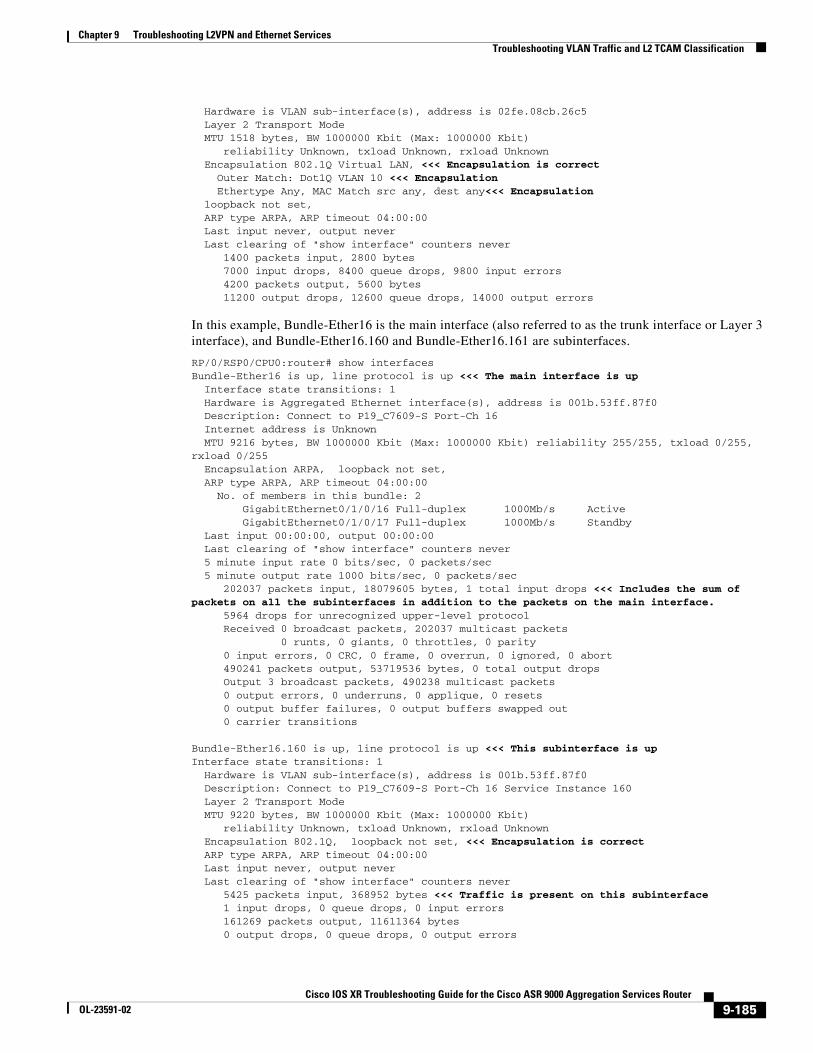
In this example, the system displays information on the subinterface 0/0/0/0.1.
RP/0/RSP0/CPU0:router# show running-config interfaceinterface GigabitEthernet0/0/0/0.1 l2transport
encapsulation dot1q 10!interface GigabitEthernet0/0/0/0.2 l2transport
encapsulation dot1q 10 second-dot1q 20...
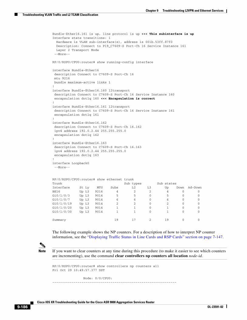
RP/0/0/CPU0:router# show interfaces GigabitEthernet 0/0/0/0.1GigabitEthernet0/0/0/0.1 is up, line protocol is up <<< This subinterface is up Interface state transitions: 1
9-184Cisco IOS XR Troubleshooting Guide for the Cisco ASR 9000 Aggregation Services Router
OL-23591-02
Chapter 9 Troubleshooting L2VPN and Ethernet Services Troubleshooting VLAN Traffic and L2 TCAM Classification
Hardware is VLAN sub-interface(s), address is 02fe.08cb.26c5 Layer 2 Transport Mode MTU 1518 bytes, BW 1000000 Kbit (Max: 1000000 Kbit) reliability Unknown, txload Unknown, rxload Unknown Encapsulation 802.1Q Virtual LAN, <<< Encapsulation is correct Outer Match: Dot1Q VLAN 10 <<< Encapsulation Ethertype Any, MAC Match src any, dest any<<< Encapsulation loopback not set, ARP type ARPA, ARP timeout 04:00:00 Last input never, output never Last clearing of "show interface" counters never 1400 packets input, 2800 bytes 7000 input drops, 8400 queue drops, 9800 input errors 4200 packets output, 5600 bytes 11200 output drops, 12600 queue drops, 14000 output errors
In this example, Bundle-Ether16 is the main interface (also referred to as the trunk interface or Layer 3 interface), and Bundle-Ether16.160 and Bundle-Ether16.161 are subinterfaces.
RP/0/RSP0/CPU0:router# show interfaces Bundle-Ether16 is up, line protocol is up <<< The main interface is up Interface state transitions: 1 Hardware is Aggregated Ethernet interface(s), address is 001b.53ff.87f0 Description: Connect to P19_C7609-S Port-Ch 16 Internet address is Unknown MTU 9216 bytes, BW 1000000 Kbit (Max: 1000000 Kbit) reliability 255/255, txload 0/255, rxload 0/255 Encapsulation ARPA, loopback not set, ARP type ARPA, ARP timeout 04:00:00 No. of members in this bundle: 2 GigabitEthernet0/1/0/16 Full-duplex 1000Mb/s Active GigabitEthernet0/1/0/17 Full-duplex 1000Mb/s Standby Last input 00:00:00, output 00:00:00 Last clearing of "show interface" counters never 5 minute input rate 0 bits/sec, 0 packets/sec 5 minute output rate 1000 bits/sec, 0 packets/sec 202037 packets input, 18079605 bytes, 1 total input drops <<< Includes the sum of packets on all the subinterfaces in addition to the packets on the main interface. 5964 drops for unrecognized upper-level protocol Received 0 broadcast packets, 202037 multicast packets 0 runts, 0 giants, 0 throttles, 0 parity 0 input errors, 0 CRC, 0 frame, 0 overrun, 0 ignored, 0 abort 490241 packets output, 53719536 bytes, 0 total output drops Output 3 broadcast packets, 490238 multicast packets 0 output errors, 0 underruns, 0 applique, 0 resets 0 output buffer failures, 0 output buffers swapped out 0 carrier transitions
Bundle-Ether16.160 is up, line protocol is up <<< This subinterface is upInterface state transitions: 1 Hardware is VLAN sub-interface(s), address is 001b.53ff.87f0 Description: Connect to P19_C7609-S Port-Ch 16 Service Instance 160 Layer 2 Transport Mode MTU 9220 bytes, BW 1000000 Kbit (Max: 1000000 Kbit) reliability Unknown, txload Unknown, rxload Unknown Encapsulation 802.1Q, loopback not set, <<< Encapsulation is correct ARP type ARPA, ARP timeout 04:00:00 Last input never, output never Last clearing of "show interface" counters never 5425 packets input, 368952 bytes <<< Traffic is present on this subinterface 1 input drops, 0 queue drops, 0 input errors 161269 packets output, 11611364 bytes 0 output drops, 0 queue drops, 0 output errors
9-185Cisco IOS XR Troubleshooting Guide for the Cisco ASR 9000 Aggregation Services Router
OL-23591-02
Chapter 9 Troubleshooting L2VPN and Ethernet Services Troubleshooting VLAN Traffic and L2 TCAM Classification
Bundle-Ether16.161 is up, line protocol is up <<< This subinterface is upInterface state transitions: 1 Hardware is VLAN sub-interface(s), address is 001b.53ff.87f0 Description: Connect to P19_C7609-S Port-Ch 16 Service Instance 161 Layer 2 Transport Mode --More--
RP/0/RSP0/CPU0:router# show running-config interface
interface Bundle-Ether16 description Connect to C7609-S Port-Ch 16 mtu 9216 bundle maximum-active links 1!interface Bundle-Ether16.160 l2transport description Connect to C7609-S Port-Ch 16 Service Instance 160 encapsulation dot1q 160 <<< Encapsulation is correct!interface Bundle-Ether16.161 l2transport description Connect to C7609-S Port-Ch 16 Service Instance 161 encapsulation dot1q 161!interface Bundle-Ether16.162 description Connect to C7609-S Port-Ch 16.162 ipv4 address 192.0.2.44 255.255.255.0 encapsulation dot1q 162!interface Bundle-Ether16.163 description Connect to C7609-S Port-Ch 16.163 ipv4 address 192.0.2.44 255.255.255.0 encapsulation dot1q 163!interface Loopback0 --More--
RP/0/RSP0/CPU0:router# show ethernet trunk Trunk Sub types Sub statesInterface St Ly MTU Subs L2 L3 Up Down Ad-DownBE16 Up L3 9216 4 2 2 4 0 0Gi0/1/0/3 Up L3 9014 5 5 0 5 0 0Gi0/1/0/7 Up L3 9014 6 6 0 6 0 0Gi0/1/0/19 Up L3 9014 2 2 0 2 0 0Gi0/1/0/20 Up L3 9014 1 1 0 1 0 0Gi0/1/0/30 Up L3 9014 1 1 0 1 0 0
Summary 19 17 2 19 0 0
The following example shows the NP counters. For a description of how to interpret NP counter information, see the “Displaying Traffic Status in Line Cards and RSP Cards” section on page 7-147.
Note If you want to clear counters at any time during this procedure (to make it easier to see which counters are incrementing), use the command clear controllers np counters all location node-id.
RP/0/RSP0/CPU0:router# show controllers np counters all Fri Oct 29 10:49:57.377 DST
Node: 0/0/CPU0:----------------------------------------------------------------
9-186Cisco IOS XR Troubleshooting Guide for the Cisco ASR 9000 Aggregation Services Router
OL-23591-02
Chapter 9 Troubleshooting L2VPN and Ethernet Services Troubleshooting VLAN Traffic and L2 TCAM Classification
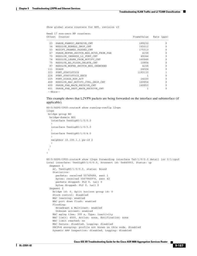
Show global stats counters for NP0, revision v3
Read 17 non-zero NP counters:Offset Counter FrameValue Rate (pps)------------------------------------------------------------------------------- 23 PARSE_FABRIC_RECEIVE_CNT 189232 0 34 RESOLVE_EGRESS_DROP_CNT 165012 0 53 MODIFY_FRAMES_PADDED_CNT 175313 0 67 PARSE_MOFRR_SWITCH_MSG_RCVD_FROM_FAB 4158 0 70 RESOLVE_INGRESS_L2_PUNT_CNT 48244 0 74 RESOLVE_LEARN_FROM_NOTIFY_CNT 160848 0 75 RESOLVE_BD_FLUSH_DELETE_CNT 10804 0 87 RESOLVE_MOFRR_SWITCH_MSG_INGNORED 4158 0 111 DIAGS 24024 0 223 PUNT_STATISTICS 1193133 1 224 PUNT_STATISTICS_EXCD 1 0 225 PUNT_DIAGS_RSP_ACT 24220 0 468 RESOLVE_MAC_NOTIFY_CTRL_DROP_CNT 160854 0 600 PARSE_FAB_MACN_RECEIVE_CNT 160853 0 601 PARSE_FAB_DEST_MACN_RECEIVE_CNT 1 0 --More--
This example shows that L2VPN packets are being forwarded on the interface and subinterface (if applicable).
RP/0/RSP0/CPU0:router# show running-config l2vpnl2vpn bridge group BG bridge-domain BD1 interface TenGigE0/1/0/0.0 ! interface TenGigE0/1/0/3.0 ! interface TenGigE0/1/0/4.0 ! neighbor 10.100.1.1 pw-id 2 ! ! !! RP/0/RSP0/CPU0:router# show l2vpn forwarding interface Te0/1/0/0.0 detail loc 0/1/cpu0Local interface: TenGigE0/1/0/0.0, Xconnect id: 0x440003, Status: up Segment 1 AC, TenGigE0/1/0/0.0, status: Bound Statistics: packets: received 55749484, sent 1 bytes: received 3567966976, sent 42 packets dropped: PLU 0, tail 0 bytes dropped: PLU 0, tail 0 Segment 2 Bridge id: 0, Split horizon group id: 0 Storm control: disabled MAC learning: enabled MAC port down flush: enabled Flooding: Broadcast & Multicast: enabled Unknown unicast: enabled MAC aging time: 300 s, Type: inactivity MAC limit: 4000, Action: none, Notification: none MAC limit reached: no MAC Secure: disabled, Logging: disabled DHCPv4 snooping: profile not known on this node, disabled Dynamic ARP Inspection: disabled, Logging: disabled
9-187Cisco IOS XR Troubleshooting Guide for the Cisco ASR 9000 Aggregation Services Router
OL-23591-02
Chapter 9 Troubleshooting L2VPN and Ethernet Services Troubleshooting VLAN Traffic and L2 TCAM Classification
IP Source Guard: disabled, Logging: disabled IGMP snooping profile: profile not known on this node Router guard disabled...Xconnect id: 0xfffc0001, Status: down Segment 1 MPLS, Destination address: 210.100.1.1, pw-id: 2, status: Not bound Pseudowire label: UNKNOWN Control word disabled Statistics: packets: received 0, sent 0 bytes: received 0, sent 0 packets dropped: PLU 0, tail 0, out of order 0 bytes dropped: PLU 0, tail 0, out of order 0 Segment 2 Bridge id: 0, Split horizon group id: 0 Storm control: disabled MAC learning: enabled MAC port down flush: enabled Flooding: Broadcast & Multicast: enabled Unknown unicast: enabled MAC aging time: 300 s, Type: inactivity MAC limit: 4000, Action: none, Notification: none MAC limit reached: no MAC Secure: disabled, Logging: disabled DHCPv4 snooping: profile not known on this node, disabled Dynamic ARP Inspection: disabled, Logging: disabled IP Source Guard: disabled, Logging: disabled IGMP snooping profile: profile not known on this node Router guard disabled
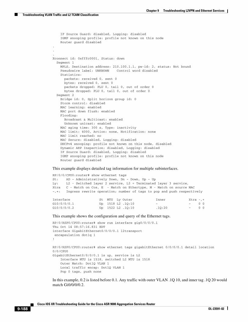
This example displays detailed tag information for multiple subinterfaces.
RP/0/0/CPU0:router# show ethernet tags St: AD - Administratively Down, Dn - Down, Up - UpLy: L2 - Switched layer 2 service, L3 = Terminated layer 3 service,Xtra C - Match on Cos, E - Match on Ethertype, M - Match on source MAC-,+: Ingress rewrite operation; number of tags to pop and push respectively
Interface St MTU Ly Outer Inner Xtra -,+Gi0/0/0/0.1 Up 1518 L2 .1Q:10 - - 0 0Gi0/0/0/0.2 Up 1522 L2 .1Q:10 .1Q:20 - 0 0
This example shows the configuration and query of the Ethernet tags.
RP/0/RSP0/CPU0:router# show run interface gig0/0/0/0.1Thu Oct 14 08:57:16.831 EDTinterface GigabitEthernet0/0/0/0.1 l2transport encapsulation dot1q 1!
RP/0/RSP0/CPU0:router# show ethernet tags gigabitEthernet 0/0/0/0.1 detail location 0/0/CPU0GigabitEthernet0/0/0/0.1 is up, service is L2 Interface MTU is 1518, switched L2 MTU is 1518 Outer Match: Dot1Q VLAN 1 Local traffic encap: Dot1Q VLAN 1 Pop 0 tags, push none
In this example, 0.2 is listed before 0.1. Any traffic with outer VLAN .1Q 10, and inner tag .1Q 20 would match Gi0/0/0/0.2.
9-188Cisco IOS XR Troubleshooting Guide for the Cisco ASR 9000 Aggregation Services Router
OL-23591-02
Chapter 9 Troubleshooting L2VPN and Ethernet Services Troubleshooting VLAN Traffic and L2 TCAM Classification
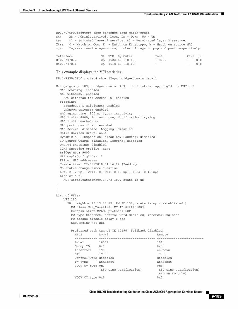
RP/0/0/CPU0:router# show ethernet tags match-orderSt: AD - Administratively Down, Dn - Down, Up - UpLy: L2 - Switched layer 2 service, L3 = Terminated layer 3 service,Xtra C - Match on Cos, E - Match on Ethertype, M - Match on source MAC-,+: Ingress rewrite operation; number of tags to pop and push respectively
Interface St MTU Ly Outer Inner Xtra -,+Gi0/0/0/0.2 Up 1522 L2 .1Q:10 .1Q:20 - 0 0Gi0/0/0/0.1 Up 1518 L2 .1Q:10 - - 0 0
This example displays the VFI statistics.
RP/0/RSP0/CPU0:router# show l2vpn bridge-domain detail
Bridge group: 189, bridge-domain: 189, id: 0, state: up, ShgId: 0, MSTi: 0 MAC learning: enabled MAC withdraw: enabled MAC withdraw for Access PW: enabled Flooding: Broadcast & Multicast: enabled Unknown unicast: enabled MAC aging time: 300 s, Type: inactivity MAC limit: 4000, Action: none, Notification: syslog MAC limit reached: no MAC port down flush: enabled MAC Secure: disabled, Logging: disabled Split Horizon Group: none Dynamic ARP Inspection: disabled, Logging: disabled IP Source Guard: disabled, Logging: disabled DHCPv4 snooping: disabled IGMP Snooping profile: none Bridge MTU: 9000 MIB cvplsConfigIndex: 1 Filter MAC addresses: Create time: 22/09/2010 04:16:14 (2w4d ago) No status change since creation ACs: 2 (2 up), VFIs: 0, PWs: 0 (0 up), PBBs: 0 (0 up) List of ACs: AC: GigabitEthernet0/1/0/3.189, state is up...List of VFIs: VFI 190 PW: neighbor 10.19.19.19, PW ID 190, state is up ( established ) PW class Use_Tu-44190, XC ID 0xfffc0003 Encapsulation MPLS, protocol LDP PW type Ethernet, control word disabled, interworking none PW backup disable delay 0 sec Sequencing not set
Preferred path tunnel TE 44190, fallback disabled MPLS Local Remote ------------ ------------------------------ ------------------------- Label 16002 101 Group ID 0x1 0x0 Interface 190 unknown MTU 1998 1998 Control word disabled disabled PW type Ethernet Ethernet VCCV CV type 0x2 0x6 (LSP ping verification) (LSP ping verification) (BFD PW FD only) VCCV CC type 0x6 0x6
9-189Cisco IOS XR Troubleshooting Guide for the Cisco ASR 9000 Aggregation Services Router
OL-23591-02
Chapter 9 Troubleshooting L2VPN and Ethernet Services Troubleshooting Multipoint Layer 2 Services
(router alert label) (router alert label) (TTL expiry) (TTL expiry) ------------ ------------------------------ ------------------------- MIB cpwVcIndex: 4294705155 Create time: 22/09/2010 04:16:14 (2w4d ago) Last time status changed: 22/09/2010 04:21:04 (2w4d ago) MAC withdraw message: send 0 receive 0 Static MAC addresses: Statistics: packets: received 849493, sent 2 bytes: received 54153872, sent 120 DHCPv4 snooping: disabled IGMP Snooping profile: none VFI Statistics: drops: illegal VLAN 0, illegal length 0
This example shows how to set up an encapsulation default subinterface. in this scenario, you expect incoming traffic on gig0/1/0/1 to be all single-tagged dot1q 100. However, you see some occasional traffic with other encapsulations being dropped. These drops could be due to a few stray packets (for example dot1q 200), and they are dropped without being processed on gig0/1/0/1; the UIDB_TCAM_MISS_AGG_DROP counter is incremented. You can configure one default subinterface to catch all the stray packets. Then the drops appear as counters on this isolated default interface, not as UIDB_TCAM_MISS_AGG_DROP on the main interface.
interface gig0/1/0/1 mtu 1500!interface gig0/1/0/1.1 l2transport encapsulation dot1q 100!interface gig0/1/0/1.2 l2transport encapsulation default <=== encapsulation default!
Troubleshooting Multipoint Layer 2 ServicesThis section explains how to troubleshoot multipoint Layer 2 services, and includes these topics:
• Basic Bridging: Example, page 9-190
• Verifying MAC Address Updates, page 9-192
• Troubleshooting Multipoint Layer 2 Bridging Services (VPLS), page 9-195
• Troubleshooting Bridge Domains That Use BGP-AD, page 9-201
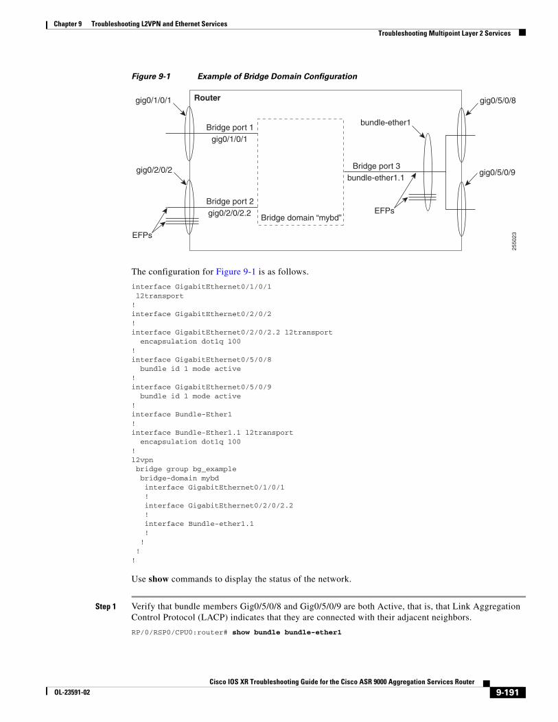
Basic Bridging: ExampleFigure 9-1 shows an example of a bridge domain configuration. The configuration commands are listed below the drawing. Make sure that your own configuration is consistent with the applicable CLI structure and syntax shown in this example.
9-190Cisco IOS XR Troubleshooting Guide for the Cisco ASR 9000 Aggregation Services Router
OL-23591-02
Chapter 9 Troubleshooting L2VPN and Ethernet Services Troubleshooting Multipoint Layer 2 Services
Figure 9-1 Example of Bridge Domain Configuration
The configuration for Figure 9-1 is as follows.
interface GigabitEthernet0/1/0/1 l2transport!interface GigabitEthernet0/2/0/2!interface GigabitEthernet0/2/0/2.2 l2transport encapsulation dot1q 100!interface GigabitEthernet0/5/0/8 bundle id 1 mode active!interface GigabitEthernet0/5/0/9 bundle id 1 mode active!interface Bundle-Ether1!interface Bundle-Ether1.1 l2transport encapsulation dot1q 100!l2vpn bridge group bg_example bridge-domain mybd interface GigabitEthernet0/1/0/1 ! interface GigabitEthernet0/2/0/2.2 ! interface Bundle-ether1.1 ! ! !!
Use show commands to display the status of the network.
Step 1 Verify that bundle members Gig0/5/0/8 and Gig0/5/0/9 are both Active, that is, that Link Aggregation Control Protocol (LACP) indicates that they are connected with their adjacent neighbors.
RP/0/RSP0/CPU0:router# show bundle bundle-ether1
2550
23
Bridge domain “mybd”
Routergig0/1/0/1
Bridge port 1gig0/1/0/1
gig0/2/0/2
Bridge port 2gig0/2/0/2.2
EFPs
Bridge port 3bundle-ether1.1
gig0/5/0/8
gig0/5/0/9
EFPs
bundle-ether1
9-191Cisco IOS XR Troubleshooting Guide for the Cisco ASR 9000 Aggregation Services Router
OL-23591-02
Chapter 9 Troubleshooting L2VPN and Ethernet Services Troubleshooting Multipoint Layer 2 Services
Note For additional information on troubleshooting bundles and LACP, see the “Troubleshooting Problems with Link Bundles” section on page 5-118.
Step 2 Follow the steps in the “Troubleshooting VLAN Traffic and L2 TCAM Classification” section on page 9-181 for the ACs—Gig0/1/0/1, Gig0/2/0/2, and Bundle-ether1.1.
Step 3 Display the bridge domain running configuration and ensure that it contains the appropriate commands for your network.
RP/0/RSP0/CPU0:router# show run l2vpn bridge group bg_example
Step 4 Verify that the bridge domain, bridge ports, and ACs are all in Up state.
RP/0/RSP0/CPU0:router# show l2vpn bridge-domain bd-name mybd
Step 5 View additional details of the bridge domain, such as the feature settings and verify they are as expected.
RP/0/RSP0/CPU0:router# show l2vpn bridge-domain bd-name mybd detail
Verifying MAC Address UpdatesThis section explains how to determine whether MAC addresses are being flooded, learned and updated, which are all prerequisites for traffic to be switched properly on the bridge domain. Even if traffic is flowing, you need to verify that the system is continuing to flood, learn, and update MAC address information appropriately.
You can track MAC learning on a specific MAC address for a node that could be several hops away. This information helps you evaluate the health of the network:
• Determine whether a source MAC address been learned on a specific bridge domain.
• Determine the specific bridge port on which the source MAC address was learned (either a PW or an AC), and provide information about the status of that bridge port.
• View the age timer on the learned MAC address, which is a statistic on the traffic stream. The system periodically checks that it is updating learned MAC addresses, and, if it is updating MAC addresses successfully, the system restarts the age timer at the initial value (0). This reset occurs at the half-age time, and the system sends a MAC update notification. If the configured maximum time elapses (default 5 minutes) without an update, the MAC address ages out, which means there is no communication and traffic is not getting through.
To find out whether a MAC address is being learned, monitor the age repeatedly, for example, every 10 seconds for five iterations. If the MAC age continues to increment beyond the half-age time, it means there is no traffic flowing during the time you monitored it.
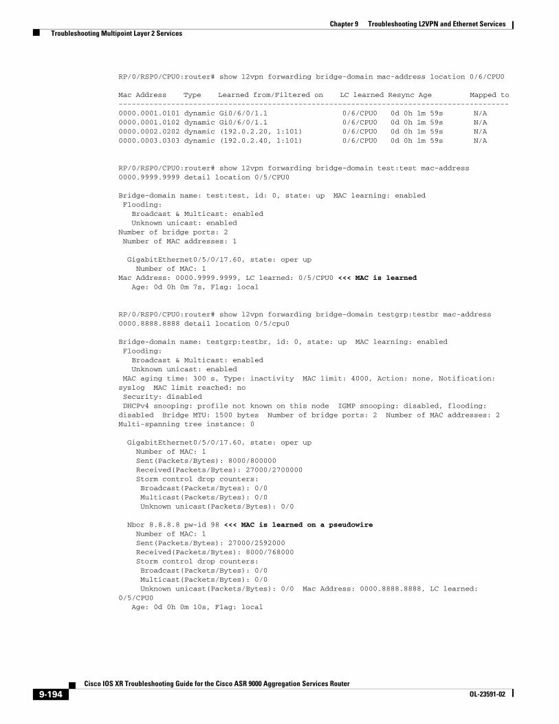
Step 1 Display the MAC address table for the bridge domain. Verify that MAC addresses are being learned and resynced. Include the specific bridge domain and MAC address of interest, so the output will display the specific bridge-port (AC or PW) on which the specific MAC address was learned.
RP/0/RSP0/CPU0:router# show l2vpn forwarding bridge-domain bridge-group:bridge-domain mac-address mac-address-id location node-id
If the MAC address was learned on a PW, the output shows the IP address of the neighbor. Otherwise it shows the MAC address of the AC.
9-192Cisco IOS XR Troubleshooting Guide for the Cisco ASR 9000 Aggregation Services Router
OL-23591-02
Chapter 9 Troubleshooting L2VPN and Ethernet Services Troubleshooting Multipoint Layer 2 Services
A bridge domain is an entity that exists on multiple LCs. However, the show command singles out one LC. If the MAC address was learned on a bridge-port on a different LC, the display output reports the LC on which it was learned—not the actual bridge-port. To get the bridge-port data, rerun the command on the actual LC on which it was learned.
Step 2 (Optional) As an alternative to the procedure in Step 1, you can run a more general command without specifying a specific bridge domain or MAC address. However, the output could flood your terminal screen.
Caution Before you run this command without specifying a particular bridge domain and MAC address, take steps to limit the amount of data that can be output on your terminal screen. Otherwise the amount of output could be extremely large.
This command displays all the MAC addresses learned on all bridge domains. As a safety mechanism, before you enter this command, set your terminal length, for example:
RP/0/RSP0/CPU0:router# term length 20
If you need the full display, direct the output to a file, for example:
RP/0/RSP0/CPU0:router# loc 0/6/cpu0 | file disk0:bdoutput.txt
RP/0/RSP0/CPU0:router# show l2vpn forwarding bridge-domain mac-address location node-id
Step 3 Display the MAC table for the bridge domain and verify that the MAC address has been learned. Notice the bridge port (the same as the attachment circuit [AC]) from which the MAC address was learned, and whether it was learned through a pseudowire (PW).
Caution Before you run this command without specifying a MAC address ID, take steps to limit the amount of data that can be output on your terminal screen. Otherwise the amount of output could be extremely large.
This command displays all the MAC addresses learned on a bridge domain. As a safety mechanism, before you enter this command, set your terminal length, for example:
RP/0/RSP0/CPU0:router# term length 20
If you need the full display, direct the output to a file, for example:
RP/0/RSP0/CPU0:router# loc 0/6/cpu0 | file disk0:bdoutput.txt
One other approach to limit the output is to run the command with a pipe filter and CTRL-C after you see the output you want.
RP/0/RSP0/CPU0:router# show l2vpn forwarding bridge-domain bridge-group:bridge-domain mac-address detail location node-id [ | begin GigabitEthernet interface-id ]
Step 4 Use the following command to display the data for a specific bridge domain and MAC address.
RP/0/RSP0/CPU0:router# show l2vpn forwarding bridge-domain bridge-group:bridge-domain mac-address mac-address detail location node-id
Example
RP/0/RSP0/CPU0:router# loc 0/6/cpu0 | file disk0:bdoutput.txt
9-193Cisco IOS XR Troubleshooting Guide for the Cisco ASR 9000 Aggregation Services Router
OL-23591-02
Chapter 9 Troubleshooting L2VPN and Ethernet Services Troubleshooting Multipoint Layer 2 Services
RP/0/RSP0/CPU0:router# show l2vpn forwarding bridge-domain mac-address location 0/6/CPU0
Mac Address Type Learned from/Filtered on LC learned Resync Age Mapped to -----------------------------------------------------------------------------------------0000.0001.0101 dynamic Gi0/6/0/1.1 0/6/CPU0 0d 0h 1m 59s N/A 0000.0001.0102 dynamic Gi0/6/0/1.1 0/6/CPU0 0d 0h 1m 59s N/A 0000.0002.0202 dynamic (192.0.2.20, 1:101) 0/6/CPU0 0d 0h 1m 59s N/A 0000.0003.0303 dynamic (192.0.2.40, 1:101) 0/6/CPU0 0d 0h 1m 59s N/A
RP/0/RSP0/CPU0:router# show l2vpn forwarding bridge-domain test:test mac-address 0000.9999.9999 detail location 0/5/CPU0
Bridge-domain name: test:test, id: 0, state: up MAC learning: enabled Flooding: Broadcast & Multicast: enabled Unknown unicast: enabledNumber of bridge ports: 2 Number of MAC addresses: 1
GigabitEthernet0/5/0/17.60, state: oper up Number of MAC: 1Mac Address: 0000.9999.9999, LC learned: 0/5/CPU0 <<< MAC is learned Age: 0d 0h 0m 7s, Flag: local
RP/0/RSP0/CPU0:router# show l2vpn forwarding bridge-domain testgrp:testbr mac-address 0000.8888.8888 detail location 0/5/cpu0
Bridge-domain name: testgrp:testbr, id: 0, state: up MAC learning: enabled Flooding: Broadcast & Multicast: enabled Unknown unicast: enabled MAC aging time: 300 s, Type: inactivity MAC limit: 4000, Action: none, Notification: syslog MAC limit reached: no Security: disabled DHCPv4 snooping: profile not known on this node IGMP snooping: disabled, flooding: disabled Bridge MTU: 1500 bytes Number of bridge ports: 2 Number of MAC addresses: 2 Multi-spanning tree instance: 0
GigabitEthernet0/5/0/17.60, state: oper up Number of MAC: 1 Sent(Packets/Bytes): 8000/800000 Received(Packets/Bytes): 27000/2700000 Storm control drop counters: Broadcast(Packets/Bytes): 0/0 Multicast(Packets/Bytes): 0/0 Unknown unicast(Packets/Bytes): 0/0
Nbor 8.8.8.8 pw-id 98 <<< MAC is learned on a pseudowire Number of MAC: 1 Sent(Packets/Bytes): 27000/2592000 Received(Packets/Bytes): 8000/768000 Storm control drop counters: Broadcast(Packets/Bytes): 0/0 Multicast(Packets/Bytes): 0/0 Unknown unicast(Packets/Bytes): 0/0 Mac Address: 0000.8888.8888, LC learned: 0/5/CPU0 Age: 0d 0h 0m 10s, Flag: local
9-194Cisco IOS XR Troubleshooting Guide for the Cisco ASR 9000 Aggregation Services Router
OL-23591-02
Chapter 9 Troubleshooting L2VPN and Ethernet Services Troubleshooting Multipoint Layer 2 Services
Troubleshooting Multipoint Layer 2 Bridging Services (VPLS)This section provides information on troubleshooting multipoint Layer 2 bridging services, also called virtual private LAN services (VPLS) on the Cisco ASR 9000 Aggregation Services Router. VPLS enables geographically separated local-area network (LAN) segments to be interconnected as a single bridged domain over an MPLS network and provides transparent multipoint Layer 2 connectivity for customers.
This section contains the following topics:
• Understanding VPLS Architecture, page 9-195
• Verifying MPLS PIE Activation, MPLS Configuration, and MPLS Connectivity, page 9-196
• Procedure for Troubleshooting Multipoint Layer 2 Services, page 9-196
• Example of Point-To-Point Layer 2 Deployment, page 9-206
Understanding VPLS Architecture
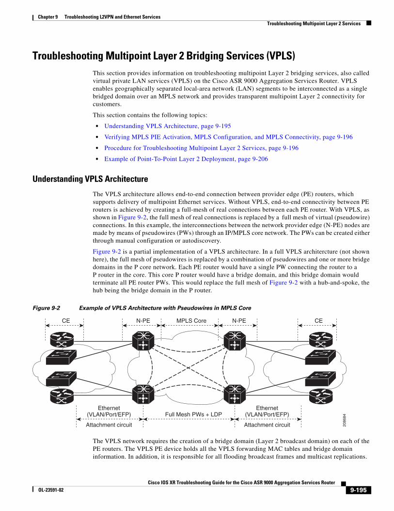
The VPLS architecture allows end-to-end connection between provider edge (PE) routers, which supports delivery of multipoint Ethernet services. Without VPLS, end-to-end connectivity between PE routers is achieved by creating a full-mesh of real connections between each PE router. With VPLS, as shown in Figure 9-2, the full mesh of real connections is replaced by a full mesh of virtual (pseudowire) connections. In this example, the interconnections between the network provider edge (N-PE) nodes are made by means of pseudowires (PWs) through an IP/MPLS core network. The PWs can be created either through manual configuration or autodiscovery.
Figure 9-2 is a partial implementation of a VPLS architecture. In a full VPLS architercture (not shown here), the full mesh of pseudowires is replaced by a combination of pseudowires and one or more bridge domains in the P core network. Each PE router would have a single PW connecting the router to a P router in the core. This core P router would have a bridge domain, and this bridge domain would terminate all PE router PWs. This would replace the full mesh of Figure 9-2 with a hub-and-spoke, the hub being the bridge domain in the P router.
Figure 9-2 Example of VPLS Architecture with Pseudowires in MPLS Core
The VPLS network requires the creation of a bridge domain (Layer 2 broadcast domain) on each of the PE routers. The VPLS PE device holds all the VPLS forwarding MAC tables and bridge domain information. In addition, it is responsible for all flooding broadcast frames and multicast replications.
N-PE N-PEMPLS Core CECE
Ethernet(VLAN/Port/EFP)
Ethernet(VLAN/Port/EFP)
Attachment circuit Attachment circuit
Full Mesh PWs + LDP
2086
84
9-195Cisco IOS XR Troubleshooting Guide for the Cisco ASR 9000 Aggregation Services Router
OL-23591-02
Chapter 9 Troubleshooting L2VPN and Ethernet Services Troubleshooting Multipoint Layer 2 Services
Verifying MPLS PIE Activation, MPLS Configuration, and MPLS Connectivity
This section is applicable to operation of multipoint Layer 2 services over PWs. For PWs to function, the MPLS PIE must be active and MPLS must be present in your running configuration:
• Verify that the MPLS PIE is installed, committed, and activated. It is not installed by default.
• Verify that MPLS is configured in your running-config. After you install the MPLS PIE, you must commit it. If you configure MPLS but you have not committed the MPLS PIE, the system deletes all of your MPLS configuration if you reload the router image.
Caution Verify that the MPLS PIE is committed before you configure MPLS. Otherwise all of your MPLS configuration data will be lost if the image is reloaded.
PWs operate over the MPLS network, therefore, MPLS connectivity is a prerequite for bringing up a PW. To verify MPLS connectivity, see the “Troubleshooting Connectivity Over MPLS” section on page 8-174.
Procedure for Troubleshooting Multipoint Layer 2 Services
Perform these steps if you are having connectivity problems with Layer 2 multipoint services.
Step 1 Check for the following underlying problems, which can cause failure of the multipoint Layer 2 services.
• The bridge domain uses an attachment circuit (AC) for which the interfaces have not been created.
• The AC interface for the bridge domain is operationally down.
• The AC interface for the bridge domain is administratively down.
• The AC is not configured as Layer 2 (the l2transport keyword is missing from the configuration command).
• The traffic on the AC interface is not classified properly (wrong encapsulation statement).
• There is an MTU mismatch between the local and remote routers.
Step 2 Verify that you can ping the opposite interface (on the remote router) from the MPLS interface.
Step 3 Verify that the remote interface shows up as an ospf neighbor.
show ospf neighbor
Step 4 Verify that the remote router ID, typically the remote router loopback, is in the routing table.
show route ipv4
Step 5 Ping the remote router with the same IP address that is used for the PW (ping x.x.x.x).
Step 6 Verify that you can find the remote router ID in an MPLS command. It should be the ipv4 address for the PW.
Step 7 Verify that the BGP neighbor is up. (This step is necessary only if BGP autodiscovery has been configured.)
show bgp neighbors
Step 8 Verify that the VFI is advertized in both PEs, and that PWs are established.
show l2vpn bridge-domain [brief | detail]
9-196Cisco IOS XR Troubleshooting Guide for the Cisco ASR 9000 Aggregation Services Router
OL-23591-02
Chapter 9 Troubleshooting L2VPN and Ethernet Services Troubleshooting Multipoint Layer 2 Services
Step 9 Check local and remote labels.
show mpls forwarding [labels]
show l2vpn forwarding detail location
Step 10 Verify that PWs are bound in the Layer 2 forwarding information base (L2FIB) with the proper cross-connect ID.
show l2vpn forwarding detail location
Step 11 Verify that NLRIs are received and PWs created.
show l2vpn discovery [summary]
Example
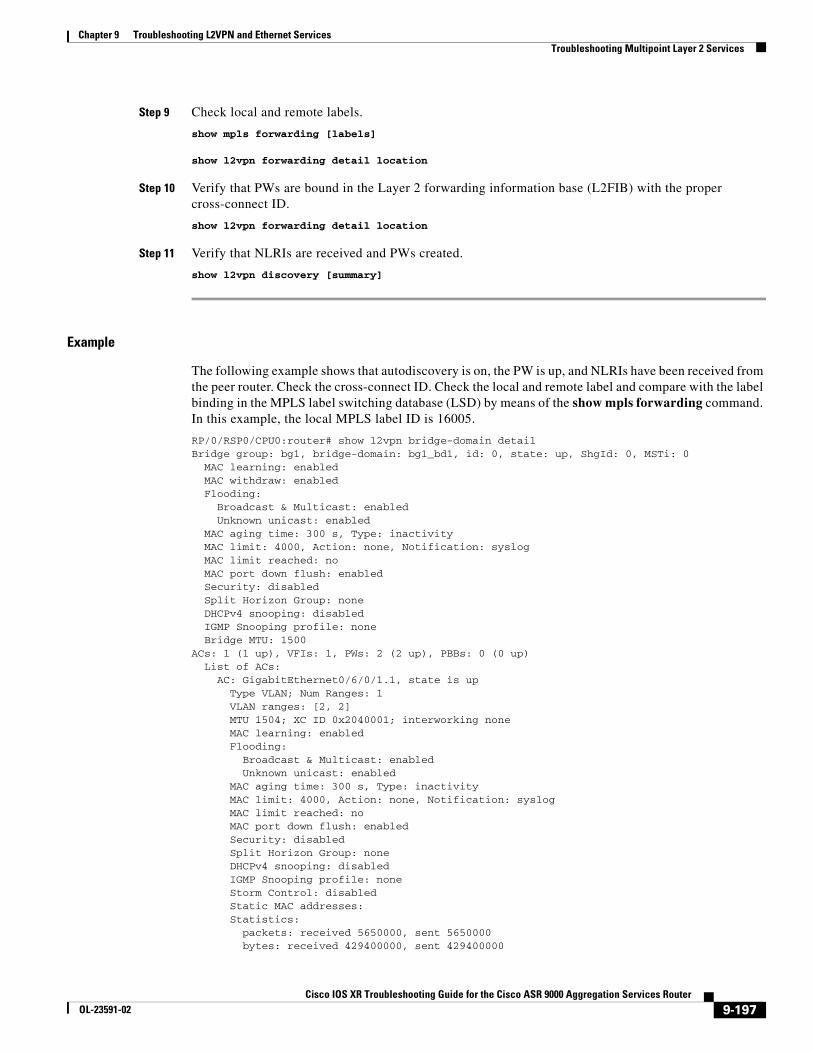
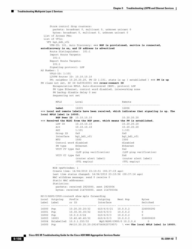
The following example shows that autodiscovery is on, the PW is up, and NLRIs have been received from the peer router. Check the cross-connect ID. Check the local and remote label and compare with the label binding in the MPLS label switching database (LSD) by means of the show mpls forwarding command. In this example, the local MPLS label ID is 16005.
RP/0/RSP0/CPU0:router# show l2vpn bridge-domain detail Bridge group: bg1, bridge-domain: bg1_bd1, id: 0, state: up, ShgId: 0, MSTi: 0 MAC learning: enabled MAC withdraw: enabled Flooding: Broadcast & Multicast: enabled Unknown unicast: enabled MAC aging time: 300 s, Type: inactivity MAC limit: 4000, Action: none, Notification: syslog MAC limit reached: no MAC port down flush: enabled Security: disabled Split Horizon Group: none DHCPv4 snooping: disabled IGMP Snooping profile: none Bridge MTU: 1500ACs: 1 (1 up), VFIs: 1, PWs: 2 (2 up), PBBs: 0 (0 up) List of ACs: AC: GigabitEthernet0/6/0/1.1, state is up Type VLAN; Num Ranges: 1 VLAN ranges: [2, 2] MTU 1504; XC ID 0x2040001; interworking none MAC learning: enabled Flooding: Broadcast & Multicast: enabled Unknown unicast: enabled MAC aging time: 300 s, Type: inactivity MAC limit: 4000, Action: none, Notification: syslog MAC limit reached: no MAC port down flush: enabled Security: disabled Split Horizon Group: none DHCPv4 snooping: disabled IGMP Snooping profile: none Storm Control: disabled Static MAC addresses: Statistics: packets: received 5650000, sent 5650000 bytes: received 429400000, sent 429400000
9-197Cisco IOS XR Troubleshooting Guide for the Cisco ASR 9000 Aggregation Services Router
OL-23591-02
Chapter 9 Troubleshooting L2VPN and Ethernet Services Troubleshooting Multipoint Layer 2 Services
Storm control drop counters: packets: broadcast 0, multicast 0, unknown unicast 0 bytes: broadcast 0, multicast 0, unknown unicast 0 List of Access PWs: List of VFIs: VFI bg1_bd1_vfi VPN-ID: 101, Auto Discovery: <<< BGP is provisioned, service is connected, autodiscovery is on, and IP address is advertized Route Distinguisher: 101:1 Import Route Targets: 101:1 Export Route Targets: 101:1 Signaling protocol: LDPAS Number: 1 VPLS-ID: 1:101 L2VPN Router ID: 10.10.10.10 PW: neighbor 10.20.20.20, PW ID 1:101, state is up ( established ) <<< PW is upPW class not set, XC ID 0xfffc0001 <<< cross-connect ID Encapsulation MPLS, Auto-discovered (BGP), protocol LDP PW type Ethernet, control word disabled, interworking none PW backup disable delay 0 sec Sequencing not set
MPLS Local Remote ------------ ------------------------------ ------------------------- Label 16005 16006 <<< Local and remote labels have been received, which indicates that signaling is up. The local MPLS label is 16005. BGP Peer ID 10.10.10.10 10.20.20.20 <<< Received the NLRI from the BGP peer, which means the PW is established. LDP ID 10.10.10.10 10.20.20.20 AII 10.10.10.10 10.20.20.20 AGI 1:101 1:101 Group ID 0x0 0x0 Interface bg1_bd1_vfi bg1_bd1_vfi MTU 1500 1500 Control word disabled disabled PW type Ethernet Ethernet VCCV CV type 0x2 0x2 (LSP ping verification) (LSP ping verification) VCCV CC type 0x6 0x6 (router alert label) (router alert label) (TTL expiry) (TTL expiry) ------------ ------------------------------ ------------------------- MIB cpwVcIndex: 1 Create time: 14/04/2010 23:10:51 (00:37:19 ago) Last time status changed: 14/04/2010 23:10:56 (00:37:14 ago) MAC withdraw message: send 0 receive 0 Static MAC addresses: Statistics: packets: received 2825000, sent 2825004 bytes: received 214700000, sent 214700304
RP/0/RSP0/CPU0:router# show mpls forwarding Local Outgoing Prefix Outgoing Next Hop Bytes Label Label or ID Interface Switched ------ ----------- ------------------ ------------ --------------- ------------16000 Pop 10.20.20.20/32 Gi0/6/0/21 10.0.0.2 226000292 16001 Pop 10.30.30.30/32 Gi0/6/0/3 10.0.0.2 0 16002 Pop 10.0.0.0/24 Gi0/6/0/3 10.0.0.2 0 16003 16003 10.40.40.40/32 Gi0/6/0/3 10.0.0.2 226000620 16004 Unlabelled 10.0.1.253/32 Mg0/RSP0/CPU0/0 10.2.0.4 0 16005 Pop PW(10.20.20.20:2814754062073957) \ <<< The local MPLS label is 16005.
9-198Cisco IOS XR Troubleshooting Guide for the Cisco ASR 9000 Aggregation Services Router
OL-23591-02
Chapter 9 Troubleshooting L2VPN and Ethernet Services Troubleshooting Multipoint Layer 2 Services
BD=0 point2point 214700000 16006 Pop PW(10.40.40.40:2814754062073957) \ BD=0 point2point 214700000
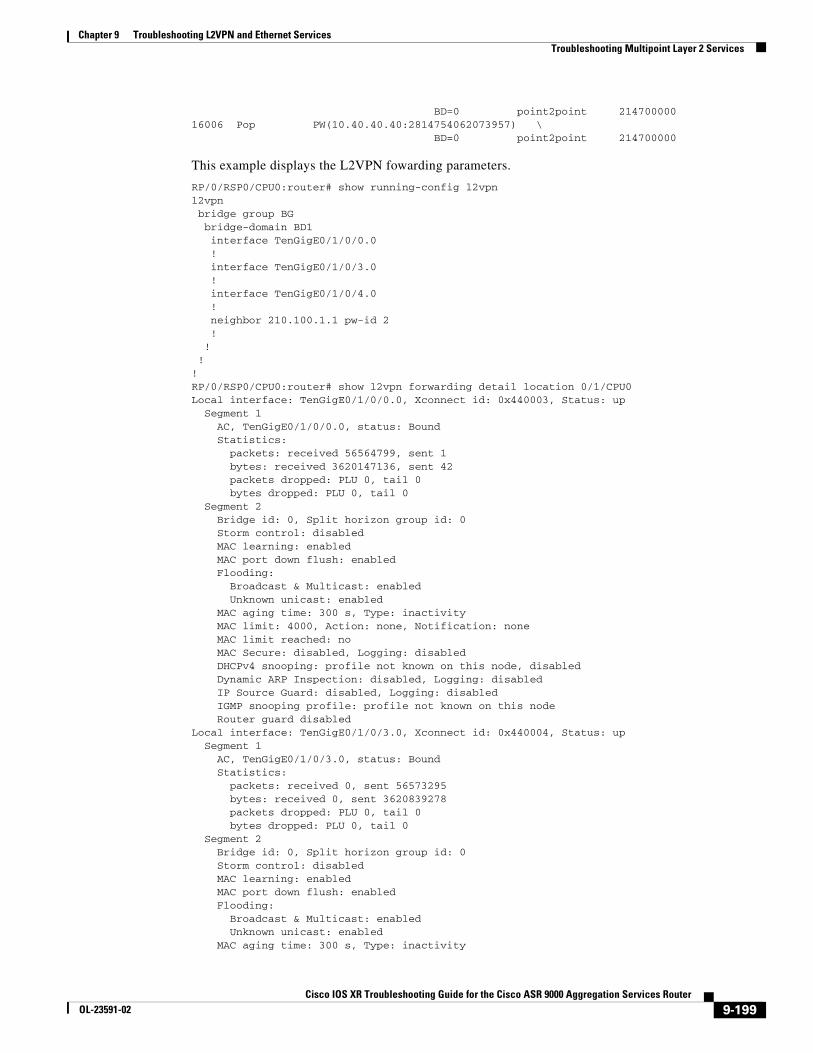
This example displays the L2VPN fowarding parameters.
RP/0/RSP0/CPU0:router# show running-config l2vpnl2vpn bridge group BG bridge-domain BD1 interface TenGigE0/1/0/0.0 ! interface TenGigE0/1/0/3.0 ! interface TenGigE0/1/0/4.0 ! neighbor 210.100.1.1 pw-id 2 ! ! !!RP/0/RSP0/CPU0:router# show l2vpn forwarding detail location 0/1/CPU0Local interface: TenGigE0/1/0/0.0, Xconnect id: 0x440003, Status: up Segment 1 AC, TenGigE0/1/0/0.0, status: Bound Statistics: packets: received 56564799, sent 1 bytes: received 3620147136, sent 42 packets dropped: PLU 0, tail 0 bytes dropped: PLU 0, tail 0 Segment 2 Bridge id: 0, Split horizon group id: 0 Storm control: disabled MAC learning: enabled MAC port down flush: enabled Flooding: Broadcast & Multicast: enabled Unknown unicast: enabled MAC aging time: 300 s, Type: inactivity MAC limit: 4000, Action: none, Notification: none MAC limit reached: no MAC Secure: disabled, Logging: disabled DHCPv4 snooping: profile not known on this node, disabled Dynamic ARP Inspection: disabled, Logging: disabled IP Source Guard: disabled, Logging: disabled IGMP snooping profile: profile not known on this node Router guard disabledLocal interface: TenGigE0/1/0/3.0, Xconnect id: 0x440004, Status: up Segment 1 AC, TenGigE0/1/0/3.0, status: Bound Statistics: packets: received 0, sent 56573295 bytes: received 0, sent 3620839278 packets dropped: PLU 0, tail 0 bytes dropped: PLU 0, tail 0 Segment 2 Bridge id: 0, Split horizon group id: 0 Storm control: disabled MAC learning: enabled MAC port down flush: enabled Flooding: Broadcast & Multicast: enabled Unknown unicast: enabled MAC aging time: 300 s, Type: inactivity
9-199Cisco IOS XR Troubleshooting Guide for the Cisco ASR 9000 Aggregation Services Router
OL-23591-02
Chapter 9 Troubleshooting L2VPN and Ethernet Services Troubleshooting Multipoint Layer 2 Services
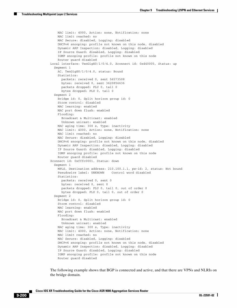
MAC limit: 4000, Action: none, Notification: none MAC limit reached: no MAC Secure: disabled, Logging: disabled DHCPv4 snooping: profile not known on this node, disabled Dynamic ARP Inspection: disabled, Logging: disabled IP Source Guard: disabled, Logging: disabled IGMP snooping profile: profile not known on this node Router guard disabledLocal interface: TenGigE0/1/0/4.0, Xconnect id: 0x440005, Status: up Segment 1 AC, TenGigE0/1/0/4.0, status: Bound Statistics: packets: received 0, sent 56573508 bytes: received 0, sent 3620856636 packets dropped: PLU 0, tail 0 bytes dropped: PLU 0, tail 0 Segment 2 Bridge id: 0, Split horizon group id: 0 Storm control: disabled MAC learning: enabled MAC port down flush: enabled Flooding: Broadcast & Multicast: enabled Unknown unicast: enabled MAC aging time: 300 s, Type: inactivity MAC limit: 4000, Action: none, Notification: none MAC limit reached: no MAC Secure: disabled, Logging: disabled DHCPv4 snooping: profile not known on this node, disabled Dynamic ARP Inspection: disabled, Logging: disabled IP Source Guard: disabled, Logging: disabled IGMP snooping profile: profile not known on this node Router guard disabledXconnect id: 0xfffc0001, Status: down Segment 1 MPLS, Destination address: 210.100.1.1, pw-id: 2, status: Not bound Pseudowire label: UNKNOWN Control word disabled Statistics: packets: received 0, sent 0 bytes: received 0, sent 0 packets dropped: PLU 0, tail 0, out of order 0 bytes dropped: PLU 0, tail 0, out of order 0 Segment 2 Bridge id: 0, Split horizon group id: 0 Storm control: disabled MAC learning: enabled MAC port down flush: enabled Flooding: Broadcast & Multicast: enabled Unknown unicast: enabled MAC aging time: 300 s, Type: inactivity MAC limit: 4000, Action: none, Notification: none MAC limit reached: no MAC Secure: disabled, Logging: disabled DHCPv4 snooping: profile not known on this node, disabled Dynamic ARP Inspection: disabled, Logging: disabled IP Source Guard: disabled, Logging: disabled IGMP snooping profile: profile not known on this node Router guard disabled
The following example shows that BGP is connected and active, and that there are VPNs and NLRIs on the bridge domain.
9-200Cisco IOS XR Troubleshooting Guide for the Cisco ASR 9000 Aggregation Services Router
OL-23591-02
Chapter 9 Troubleshooting L2VPN and Ethernet Services Troubleshooting Multipoint Layer 2 Services
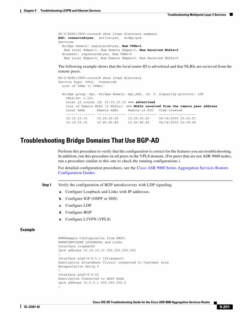
RP/0/RSP0/CPU0:router# show l2vpn discovery summary BGP: connected=yes, active=yes, stdby=yesServices Bridge domain: registered=yes, Num VPNs=1 Num Local Edges=1, Num Remote Edges=2, Num Received NLRIs=2 Xconnect: registered=yes, Num VPNs=0 Num Local Edges=0, Num Remote Edges=0, Num Received NLRIs=0
The following example shows that the local router ID is advertised and that NLRIs are recieved from the remote peers.
RP/0/RSP0/CPU0:router# show l2vpn discoveryService Type: VPLS, Connected List of VPNs (1 VPNs):
Bridge group: bg1, bridge-domain: bg1_bd1, id: 0, signaling protocol: LDP VPLS-ID: 1:101 Local L2 router id: 10.10.10.10 <<< advertised List of Remote NLRI (2 NLRIs): <<< NLRIs received from the remote peer address Local Addr Remote Addr Remote L2 RID Time Created --------------- --------------- --------------- ------------------- 10.10.10.10 10.20.20.20 10.20.20.20 04/14/2010 23:10:51 10.10.10.10 10.40.40.40 10.40.40.40 04/14/2010 23:19:06
Troubleshooting Bridge Domains That Use BGP-ADPerform this procedure to verify that the configuration is correct for the features you are troubleshooting. In addition, run this procedure on all peers in the VPLS domain. (For peers that are not ASR 9000 nodes, run a procedure similar to this one to check the running configurations.)
For detailed configuration procedures, see the Cisco ASR 9000 Series Aggregation Services Routers Configuration Guides.
Step 1 Verify the configuration of BGP autodiscovery with LDP signaling.
a. Configure Loopback and Links with IP addresses.
b. Configure IGP (OSPF or ISIS)
c. Configure LDP
d. Configure BGP
e. Configure L2VPN (VPLS)
Example
####Sample Configuration from WEST:####CONFIGURE LOOPBACKs and LinksInterface loopback0Ipv4 address 10.10.10.10 255.255.255.255!Interface gig0/6/0/1.1 l2transportDescription Attachment Circuit connected to Customer siteEncapsulation dot1q 2!Interface gig0/6/0/21Description Connected to EAST NodeIpv4 address 10.0.0.1 255.255.255.0!
9-201Cisco IOS XR Troubleshooting Guide for the Cisco ASR 9000 Aggregation Services Router
OL-23591-02
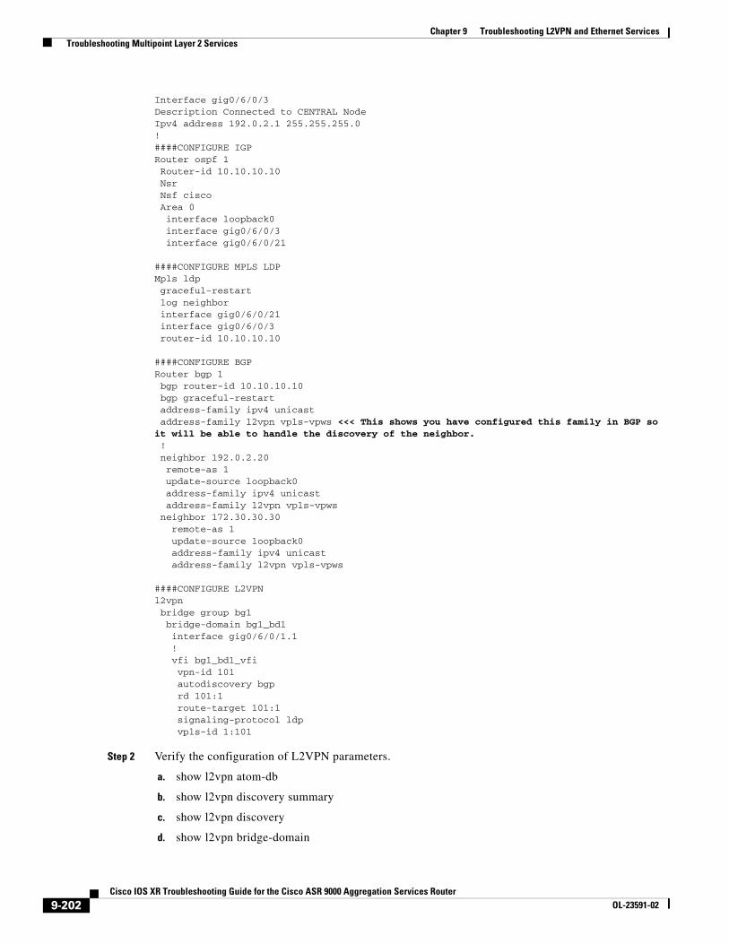
Chapter 9 Troubleshooting L2VPN and Ethernet Services Troubleshooting Multipoint Layer 2 Services
Interface gig0/6/0/3Description Connected to CENTRAL NodeIpv4 address 192.0.2.1 255.255.255.0!####CONFIGURE IGPRouter ospf 1 Router-id 10.10.10.10 Nsr Nsf cisco Area 0 interface loopback0 interface gig0/6/0/3 interface gig0/6/0/21
####CONFIGURE MPLS LDPMpls ldp graceful-restart log neighbor interface gig0/6/0/21 interface gig0/6/0/3 router-id 10.10.10.10
####CONFIGURE BGPRouter bgp 1 bgp router-id 10.10.10.10 bgp graceful-restart address-family ipv4 unicast address-family l2vpn vpls-vpws <<< This shows you have configured this family in BGP so it will be able to handle the discovery of the neighbor. ! neighbor 192.0.2.20 remote-as 1 update-source loopback0 address-family ipv4 unicast address-family l2vpn vpls-vpws neighbor 172.30.30.30 remote-as 1 update-source loopback0 address-family ipv4 unicast address-family l2vpn vpls-vpws
####CONFIGURE L2VPNl2vpn bridge group bg1 bridge-domain bg1_bd1 interface gig0/6/0/1.1 ! vfi bg1_bd1_vfi vpn-id 101 autodiscovery bgp rd 101:1 route-target 101:1 signaling-protocol ldp vpls-id 1:101
Step 2 Verify the configuration of L2VPN parameters.
a. show l2vpn atom-db
b. show l2vpn discovery summary
c. show l2vpn discovery
d. show l2vpn bridge-domain
9-202Cisco IOS XR Troubleshooting Guide for the Cisco ASR 9000 Aggregation Services Router
OL-23591-02
Chapter 9 Troubleshooting L2VPN and Ethernet Services Troubleshooting Multipoint Layer 2 Services
e. show l2vpn bridge-domain brief
f. show l2vpn bridge-domain detail
Example
RP/0/RSP0/CPU0:router# show l2vpn atom-db Wed Apr 14 23:28:41.905 EDT
Peer ID VC ID Encap Signaling FEC Discovery ____________________________________________________________________________
192.0.2.20 1:101 MPLS LDP 129 BGP 192.168.40.40 1:101 MPLS LDP 129 BGP
RP/0/RSP0/CPU0:router# show l2vpn discovery summary Wed Apr 14 23:24:46.156 EDTBGP: connected=yes, active=yes, stdby=yesServices Bridge domain: registered=yes, Num VPNs=1 Num Local Edges=1, Num Remote Edges=2, Num Received NLRIs=2 Xconnect: registered=yes, Num VPNs=0 Num Local Edges=0, Num Remote Edges=0, Num Received NLRIs=0
RP/0/RSP0/CPU0:router# show l2vpn discovery Wed Apr 14 23:23:00.513 EDT
Service Type: VPLS, Connected List of VPNs (1 VPNs):
Bridge group: bg1, bridge-domain: bg1_bd1, id: 0, signaling protocol: LDP VPLS-ID: 1:101 Local L2 router id: 10.10.10.10 <<< advertized List of Remote NLRI (2 NLRIs): <<< NLRIs received from those remote peer addresses Local Addr Remote Addr Remote L2 RID Time Created --------------- --------------- --------------- ------------------- 10.10.10.10 192.0.2.20 192.0.2.20 04/14/2010 23:10:51 10.10.10.10 192.168.40.40 192.168.40.40 04/14/2010 23:19:06
RP/0/RSP0/CPU0:router# show l2vpn bridge-domain Wed Apr 14 23:46:37.190 EDTBridge group: bg1, bridge-domain: bg1_bd1, id: 0, state: up, ShgId: 0, MSTi: 0 Aging: 300 s, MAC limit: 4000, Action: none, Notification: syslog Filter MAC addresses: 0 ACs: 1 (1 up), VFIs: 1, PWs: 2 (2 up), PBBs: 0 (0 up) List of ACs: Gi0/6/0/1.1, state: up, Static MAC addresses: 0 List of Access PWs: List of VFIs: VFI bg1_bd1_vfi Neighbor 192.0.2.20 pw-id 1:101, state: up, Static MAC addresses: 0 Neighbor 192.168.40.40 pw-id 1:101, state: up, Static MAC addresses: 0
RP/0/RSP0/CPU0:router# show l2vpn bridge-domain brief Wed Apr 14 23:47:42.003 EDTBridge Group/Bridge-Domain Name ID State Num ACs/up Num PWs/up-------------------------------- ----- ---------- -------------- --------------bg1/bg1_bd1 0 up 1/1 2/2
9-203Cisco IOS XR Troubleshooting Guide for the Cisco ASR 9000 Aggregation Services Router
OL-23591-02
Chapter 9 Troubleshooting L2VPN and Ethernet Services Troubleshooting Multipoint Layer 2 Services
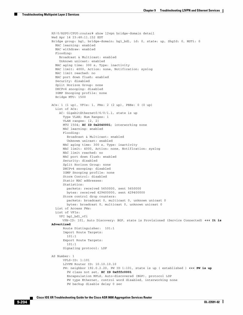
RP/0/RSP0/CPU0:router# show l2vpn bridge-domain detail Wed Apr 14 23:48:11.152 EDTBridge group: bg1, bridge-domain: bg1_bd1, id: 0, state: up, ShgId: 0, MSTi: 0 MAC learning: enabled MAC withdraw: enabled Flooding: Broadcast & Multicast: enabled Unknown unicast: enabled MAC aging time: 300 s, Type: inactivity MAC limit: 4000, Action: none, Notification: syslog MAC limit reached: no MAC port down flush: enabled Security: disabled Split Horizon Group: none DHCPv4 snooping: disabled IGMP Snooping profile: none Bridge MTU: 1500
ACs: 1 (1 up), VFIs: 1, PWs: 2 (2 up), PBBs: 0 (0 up) List of ACs: AC: GigabitEthernet0/6/0/1.1, state is up Type VLAN; Num Ranges: 1 VLAN ranges: [2, 2] MTU 1504; XC ID 0x2040001; interworking none MAC learning: enabled Flooding: Broadcast & Multicast: enabled Unknown unicast: enabled MAC aging time: 300 s, Type: inactivity MAC limit: 4000, Action: none, Notification: syslog MAC limit reached: no MAC port down flush: enabled Security: disabled Split Horizon Group: none DHCPv4 snooping: disabled IGMP Snooping profile: none Storm Control: disabled Static MAC addresses: Statistics: packets: received 5650000, sent 5650000 bytes: received 429400000, sent 429400000 Storm control drop counters: packets: broadcast 0, multicast 0, unknown unicast 0 bytes: broadcast 0, multicast 0, unknown unicast 0 List of Access PWs: List of VFIs: VFI bg1_bd1_vfi VPN-ID: 101, Auto Discovery: BGP, state is Provisioned (Service Connected) <<< It is Advertized Route Distinguisher: 101:1 Import Route Targets: 101:1 Export Route Targets: 101:1 Signaling protocol: LDP
AS Number: 1 VPLS-ID: 1:101 L2VPN Router ID: 10.10.10.10 PW: neighbor 192.0.2.20, PW ID 1:101, state is up ( established ) <<< PW is up PW class not set, XC ID 0xfffc0001 Encapsulation MPLS, Auto-discovered (BGP), protocol LDP PW type Ethernet, control word disabled, interworking none PW backup disable delay 0 sec
9-204Cisco IOS XR Troubleshooting Guide for the Cisco ASR 9000 Aggregation Services Router
OL-23591-02
Chapter 9 Troubleshooting L2VPN and Ethernet Services Troubleshooting Multipoint Layer 2 Services
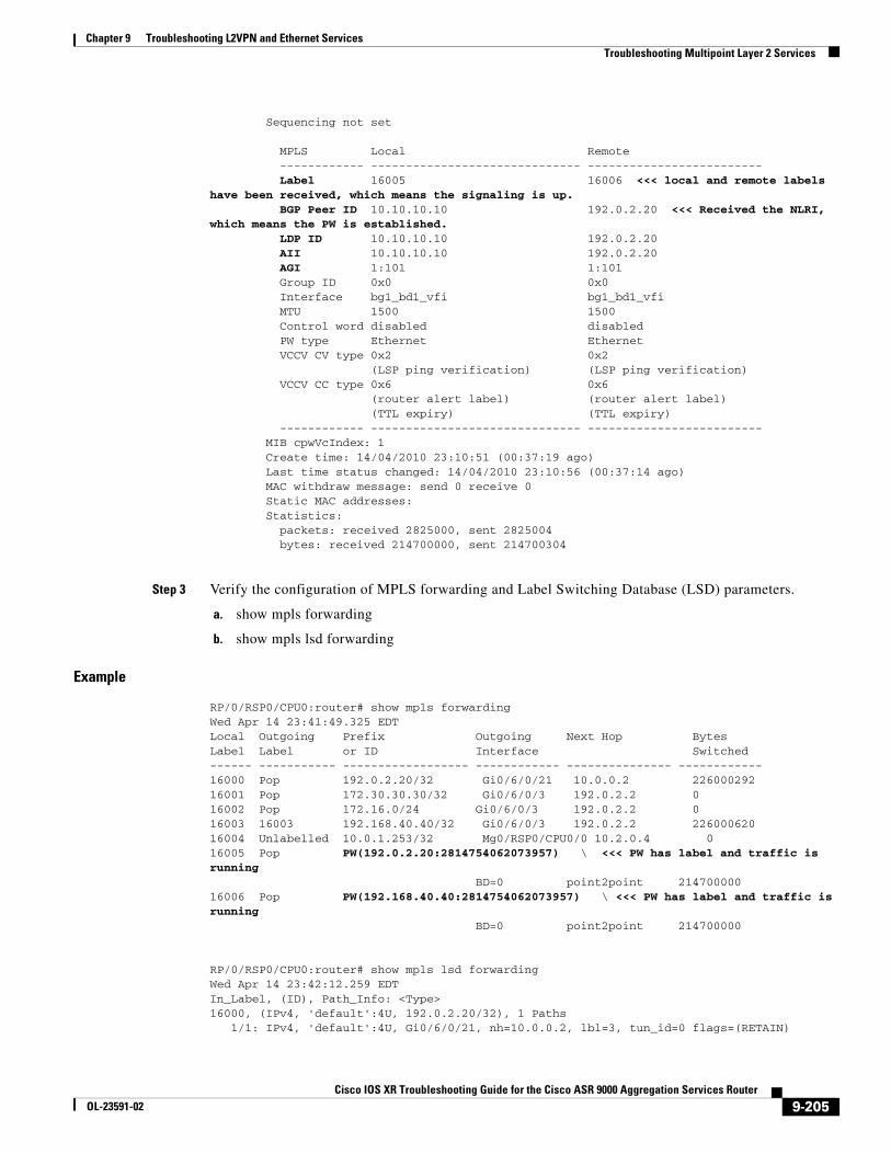
Sequencing not set
MPLS Local Remote ------------ ------------------------------ ------------------------- Label 16005 16006 <<< local and remote labels have been received, which means the signaling is up. BGP Peer ID 10.10.10.10 192.0.2.20 <<< Received the NLRI, which means the PW is established. LDP ID 10.10.10.10 192.0.2.20 AII 10.10.10.10 192.0.2.20 AGI 1:101 1:101 Group ID 0x0 0x0 Interface bg1_bd1_vfi bg1_bd1_vfi MTU 1500 1500 Control word disabled disabled PW type Ethernet Ethernet VCCV CV type 0x2 0x2 (LSP ping verification) (LSP ping verification) VCCV CC type 0x6 0x6 (router alert label) (router alert label) (TTL expiry) (TTL expiry) ------------ ------------------------------ ------------------------- MIB cpwVcIndex: 1 Create time: 14/04/2010 23:10:51 (00:37:19 ago) Last time status changed: 14/04/2010 23:10:56 (00:37:14 ago) MAC withdraw message: send 0 receive 0 Static MAC addresses: Statistics: packets: received 2825000, sent 2825004 bytes: received 214700000, sent 214700304
Step 3 Verify the configuration of MPLS forwarding and Label Switching Database (LSD) parameters.
a. show mpls forwarding
b. show mpls lsd forwarding
Example
RP/0/RSP0/CPU0:router# show mpls forwarding Wed Apr 14 23:41:49.325 EDTLocal Outgoing Prefix Outgoing Next Hop Bytes Label Label or ID Interface Switched ------ ----------- ------------------ ------------ --------------- ------------16000 Pop 192.0.2.20/32 Gi0/6/0/21 10.0.0.2 226000292 16001 Pop 172.30.30.30/32 Gi0/6/0/3 192.0.2.2 0 16002 Pop 172.16.0/24 Gi0/6/0/3 192.0.2.2 0 16003 16003 192.168.40.40/32 Gi0/6/0/3 192.0.2.2 226000620 16004 Unlabelled 10.0.1.253/32 Mg0/RSP0/CPU0/0 10.2.0.4 0 16005 Pop PW(192.0.2.20:2814754062073957) \ <<< PW has label and traffic is running BD=0 point2point 214700000 16006 Pop PW(192.168.40.40:2814754062073957) \ <<< PW has label and traffic is running BD=0 point2point 214700000
RP/0/RSP0/CPU0:router# show mpls lsd forwarding Wed Apr 14 23:42:12.259 EDTIn_Label, (ID), Path_Info: <Type>16000, (IPv4, 'default':4U, 192.0.2.20/32), 1 Paths 1/1: IPv4, 'default':4U, Gi0/6/0/21, nh=10.0.0.2, lbl=3, tun_id=0 flags=(RETAIN)
9-205Cisco IOS XR Troubleshooting Guide for the Cisco ASR 9000 Aggregation Services Router
OL-23591-02
Chapter 9 Troubleshooting L2VPN and Ethernet Services Troubleshooting Point-to-Point Layer 2 Services
16001, (IPv4, 'default':4U, 172.30.30.30/32), 1 Paths 1/1: IPv4, 'default':4U, Gi0/6/0/3, nh=20.0.0.2, lbl=3, tun_id=0 flags=(RETAIN) 16002, (IPv4, 'default':4U, 172.16.0.0/24), 1 Paths 1/1: IPv4, 'default':4U, Gi0/6/0/3, nh=20.0.0.2, lbl=3, tun_id=0 flags=(RETAIN) 16003, (IPv4, 'default':4U, 192.168.40.40/32), 1 Paths 1/1: IPv4, 'default':4U, Gi0/6/0/3, nh=20.0.0.2, lbl=16003, tun_id=0 flags=(RETAIN) 16004, (IPv4, 'default':4U, 10.0.1.253/32), 1 Paths 1/1: IPv4, 'default':4U, Null, nh=10.2.0.4, lbl=None, tun_id=0 flags=() 16005, (PW, (192.0.2.20:2814754062073957)), 1 Paths 1/1: PW, bridge_id=0, shg_id=1, xc_id=0xfffc0001, f=0x4, lbl=Pop-PW-Ether [Attached]16006, (PW, (192.168.40.40:2814754062073957)), 1 Paths 1/1: PW, bridge_id=0, shg_id=1, xc_id=0xfffc0002, f=0x4, lbl=Pop-PW-Ether [Attached]
Troubleshooting Point-to-Point Layer 2 ServicesThis section provides information on troubleshooting point-to-point Layer 2 services. It contains the following subsections:
• Example of Point-To-Point Layer 2 Deployment, page 9-206
• Using show and debug Commands, page 9-210
• AC Is Down, page 9-218
• Pseudowire Is Down, page 9-219
• VPWS Not Forwarding Traffic from AC to Pseudowire, page 9-212
• Pseudowire Up but Ping Fails, page 9-213
• Traffic Loss, page 9-213
• Traffic Loss During RSP Fail Over, page 9-213
• Preferred Path Not Working, page 9-214
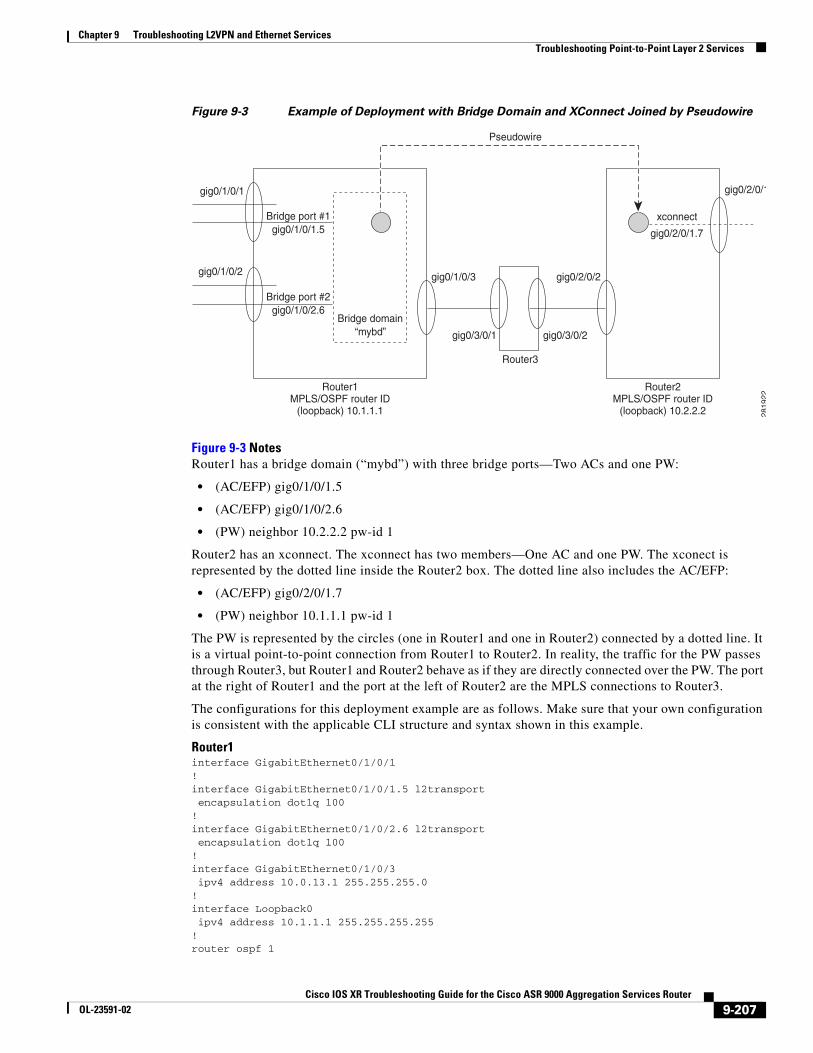
Example of Point-To-Point Layer 2 DeploymentThis section contains an example of a point-to-point Layer 2 deployment involving a router with a bridge domain on one side of the network and a router with a cross-connect on the other. The two routers are connected by a PW. The PW is a virtual point-to-point connection between the two routers. As shown in Figure 9-3, the traffic for the PW (the virtual connection between Routers 1 and 2) passes through Router3, but Routers 1 and 2 behave as if they are directly connected over the PW.
9-206Cisco IOS XR Troubleshooting Guide for the Cisco ASR 9000 Aggregation Services Router
OL-23591-02
Chapter 9 Troubleshooting L2VPN and Ethernet Services Troubleshooting Point-to-Point Layer 2 Services
Figure 9-3 Example of Deployment with Bridge Domain and XConnect Joined by Pseudowire
Figure 9-3 NotesRouter1 has a bridge domain (“mybd”) with three bridge ports—Two ACs and one PW:
• (AC/EFP) gig0/1/0/1.5
• (AC/EFP) gig0/1/0/2.6
• (PW) neighbor 10.2.2.2 pw-id 1
Router2 has an xconnect. The xconnect has two members—One AC and one PW. The xconect is represented by the dotted line inside the Router2 box. The dotted line also includes the AC/EFP:
• (AC/EFP) gig0/2/0/1.7
• (PW) neighbor 10.1.1.1 pw-id 1
The PW is represented by the circles (one in Router1 and one in Router2) connected by a dotted line. It is a virtual point-to-point connection from Router1 to Router2. In reality, the traffic for the PW passes through Router3, but Router1 and Router2 behave as if they are directly connected over the PW. The port at the right of Router1 and the port at the left of Router2 are the MPLS connections to Router3.
The configurations for this deployment example are as follows. Make sure that your own configuration is consistent with the applicable CLI structure and syntax shown in this example.
Router1interface GigabitEthernet0/1/0/1!interface GigabitEthernet0/1/0/1.5 l2transport encapsulation dot1q 100!interface GigabitEthernet0/1/0/2.6 l2transport encapsulation dot1q 100!interface GigabitEthernet0/1/0/3 ipv4 address 10.0.13.1 255.255.255.0!interface Loopback0 ipv4 address 10.1.1.1 255.255.255.255!router ospf 1
gig0/1/0/1
gig0/1/0/2
Bridge port #1gig0/1/0/1.5 gig0/2/0/1.7
xconnect
Bridge port #2gig0/1/0/2.6
Bridge domain“mybd”
Router1MPLS/OSPF router ID
(loopback) 10.1.1.1
Router2MPLS/OSPF router ID
(loopback) 10.2.2.2
Pseudowire
gig0/1/0/3 gig0/2/0/2
gig0/2/0/1
gig0/3/0/1 gig0/3/0/2
Router3
2819
22
9-207Cisco IOS XR Troubleshooting Guide for the Cisco ASR 9000 Aggregation Services Router
OL-23591-02
Chapter 9 Troubleshooting L2VPN and Ethernet Services Troubleshooting Point-to-Point Layer 2 Services
log adjacency changes router-id 10.1.1.1 area 0 interface GigabitEthernet0/1/0/3 ! interface Loopback0 ! !!mpls ldp router-id 10.1.1.1 log neighbor ! interface GigabitEthernet0/1/0/3 !!l2vpn bridge group examples bridge-domain mybd interface GigabitEthernet0/1/0/1.5 ! interface GigabitEthernet0/1/0/2.6 ! neighbor 10.2.2.2 pw-id 1 ! ! !!
Router2interface GigabitEthernet0/2/0/1!interface GigabitEthernet0/2/0/1.7 l2transport encapsulation dot1q 100!interface GigabitEthernet0/2/0/2 ipv4 address 10.0.23.1 255.255.255.0!interface Loopback0 ipv4 address 10.2.2.2 255.255.255.255!router ospf 1 log adjacency changes router-id 10.2.2.2 area 0 interface GigabitEthernet0/2/0/2 ! interface Loopback0 ! !!mpls ldp router-id 10.2.2.2 log neighbor ! interface GigabitEthernet0/2/0/2 !!l2vpn xconnect group examples p2p myxc
9-208Cisco IOS XR Troubleshooting Guide for the Cisco ASR 9000 Aggregation Services Router
OL-23591-02
Chapter 9 Troubleshooting L2VPN and Ethernet Services Troubleshooting Point-to-Point Layer 2 Services
interface GigabitEthernet0/2/0/1.7 ! neighbor 10.1.1.1 pw-id 1 ! !!
Router 3interface GigabitEthernet0/3/0/1 ipv4 address 10.0.13.2 255.255.255.0!interface GigabitEthernet0/3/0/2 ipv4 address 10.0.23.2 255.255.255.0!interface Loopback0 ipv4 address 10.3.3.3 255.255.255.255!router ospf 1 log adjacency changes router-id 10.3.3.3 area 0 interface GigabitEthernet0/3/0/1 ! interface GigabitEthernet0/3/0/2 ! interface Loopback0 ! !!mpls ldp router-id 10.3.3.3 log neighbor ! interface GigabitEthernet0/3/0/1 ! interface GigabitEthernet0/3/0/2 !!
Use the following procedure to locate any problems with traffic flow in this network. The IP addresses are based on the sample configurations for Routers 1, 2, and 3 (above).
Step 1 Verify ping connectivity over the MPLS links.
• From Router1 gig0/1/0/3 to Router3 gig0/3/0/1—ping 10.0.13.2
• From Router2 gig0/2/0/2 to Router3 gig0/3/0/2—ping 10.0.23.2
Step 2 Verify that OSPF neighbor links are up on the links (the same links listed in Step 1).
RP/0/RSP0/CPU0:router# show ospf neighbor
Step 3 Verify that the Router1 routing table contains the loopback address of Router2 (10.2.2.2). Also verify that the Router2 routing table contains the loopback address of Router1 (10.1.1.1).
RP/0/RSP0/CPU0:router# show route ipv4
Step 4 Verify that Router1 can ping the Router2 loopback address, and Router2 can ping the Router1 loopback address.
• From Router1—ping 10.2.2.2
• From Router2—ping 10.1.1.1
9-209Cisco IOS XR Troubleshooting Guide for the Cisco ASR 9000 Aggregation Services Router
OL-23591-02
Chapter 9 Troubleshooting L2VPN and Ethernet Services Troubleshooting Point-to-Point Layer 2 Services
Step 5 Verify that MPLS neighbors are established in the links (the same links listed in Step 1).
RP/0/RSP0/CPU0:router# show mpls ldp neighbor
Step 6 Verify that Router1 has an MPLS label to reach the Router2 loopback address. Also verify that Router2 has an MPLS label to reach the Router1 loopback address.
Note The output of this command contains one additional MPLS label. This additional label represents the pseudowire between Router1 and Router2.
RP/0/RSP0/CPU0:router# show mpls forwarding
Step 7 Verify that the status of the Router1 bridge domain is UP, and that all all ACs are up.
RP/0/RSP0/CPU0:router# show l2vpn bridge-domain mybd
Step 8 Verify that the status of the Router1 PW is UP.
RP/0/RSP0/CPU0:router# show l2vpn bridge-domain mybd
Step 9 Verify that the Router2 xconnect is UP, and all ACs are UP.
RP/0/RSP0/CPU0:router# show l2vpn xconnect group examples
Step 10 Verify that the Router2 PW is UP.
RP/0/RSP0/CPU0:router# show l2vpn xconnect group examples
Using show and debug Commands
SUMMARY STEPS
1. show l2vpn xconnect [detail | group | interface | neighbor | state | summary | type | state unresolved]
2. show l2vpn forwarding {detail | hardware | interface | location | message | resource | summary | unresolved} location node-id
3. show mpls forwarding [detail | {label label number} | interface interface-id | labels value | location | prefix [network/mask | length] | summary | tunnels tunnel-id]
9-210Cisco IOS XR Troubleshooting Guide for the Cisco ASR 9000 Aggregation Services Router
OL-23591-02
Chapter 9 Troubleshooting L2VPN and Ethernet Services Troubleshooting Point-to-Point Layer 2 Services
DETAILED STEPS
AC Is Down
Step 1 View the interface state.
RP/0/RSP0/CPU0:router# show interface
Step 2 View the state of the xconnect.
RP/0/RSP0/CPU0:router# show l2vpn xconnect detail
Step 3 Ensure that the AC interface has l2transport configured.
Step 4 Ensure that the AC interface is up.
Step 5 Ensure that the MTUs match.
RP/0/RSP0/CPU0:router# show l2vpn bridge-domain interface type interface-name detail
Command or Action Purpose
Step 1 show l2vpn xconnect [detail | group | interface | neighbor | state | summary | type | state unresolved]
Example:RP/0/RSP0/CPU0:router# show l2vpn xconnect
View brief information on configured cross-connects. Filter results using the following parameters and keywords:
• detail—Detailed information
• group—All cross-connects in a specified group
• interface—Interface and subinterface
• neighbor—Neighbor
• state—Xconnect state types: up, down
• summary—AC information from the AC Manager database
• type—Xconnect types: ac-pw, locally switched
• state unresolved—Unresolved cross-connects
Step 2 show l2vpn forwarding {detail | hardware | interface | location | message | resource | summary | unresolved} location node-id
Example:RP/0/RSP0/CPU0:router# show l2vpn forwarding location 0/2/cpu0
View the matching AC subinterface.
Step 3 show mpls forwarding [detail | {label label number} | interface interface-id | labels value | location | prefix [network/mask | length] | summary | tunnels tunnel-id]
View the MPLS Label Forwarding Information Base (LFIB) entries with a local labels range.
9-211Cisco IOS XR Troubleshooting Guide for the Cisco ASR 9000 Aggregation Services Router
OL-23591-02
Chapter 9 Troubleshooting L2VPN and Ethernet Services Troubleshooting Point-to-Point Layer 2 Services
Pseudowire Is Down
Step 1 View the pseudowire state.
RP/0/RSP0/CPU0:router# show l2vpn xconnect neighbor
Step 2 On the MPLS-enabled interface that connects to the router at the remote end of the PW, view MPLS LDP neighbor information. Check these conditions:
a. Ensure that, if the MPLS router-id uses a loopback interface (it usually does), the loopback interface is present in the OSPF configuration, so that a route to its address is advertised for the other router to reach.
b. Ensure that an LDP session is established with the PE peer.
RP/0/RSP0/CPU0:router# show mpls ldp neighbor neighbor
Step 3 Ensure that the MPLS infrastructure has allocated a label for the mpls-id IP address on the opposite router, and an additional label for the PW tunnel itself.
RP/0/RSP0/CPU0:router# show mpls forwarding
Step 4 (Perform this step if the MPLS LSP does not come up.) On the MPLS-enabled interface that connects to the router at the remote end of the PW, view OSPF neighbor information. Verify that the IP address of the MPLS router ID is reachable:
a. Ensure that this IP address appears in the routing table.
b. Ping this IP address and verify that it replies successfully.
c. Ensure that the PW ID (keyword "pw-id" in the configuration syntax) is identical on both ends of the PW.
RP/0/RSP0/CPU0:router# show ospf neighbor
Step 5 Ensure that pseudowires are properly configured on both PEs.
Step 6 Ensure that the MPLS package is installed.
Step 7 Ensure that the core interface is up.
Step 8 Ensure that OSPF is the routing protocol.
Step 9 Ensure that the MTUs match.
RP/0/RSP0/CPU0:router# show l2vpn xconnect neighbor
VPWS Not Forwarding Traffic from AC to PseudowireThis section provides information on troubleshooting forwarding of traffic from the AC to the PW over virtual private wire services (VPWS). VPWS connects to endpoints defined by physical interfaces or subinterfaces by emulating a virtual wire between them using the underlying MPLS technology.
Step 1 View pseudowire hardware information.
RP/0/RSP0/CPU0:router# show l2vpn forwarding neighbor 192.168.12.5 pw-id 100 hardware
egress location node-id0
9-212Cisco IOS XR Troubleshooting Guide for the Cisco ASR 9000 Aggregation Services Router
OL-23591-02
Chapter 9 Troubleshooting L2VPN and Ethernet Services Troubleshooting Point-to-Point Layer 2 Services
Step 2 View the bridge information about Broadcast, Multicast and Unknown Unicast.
RP/0/RSP0/CPU0:router# show l2vpn bridge-domain bd-name 1 det
Step 3 Ensure that the MAC limit has not been exceeded.
RP/0/RSP0/CPU0:router# show l2vpn forwarding bridge-domain 1:1 detail location
Step 4 Ensure that the pseudowires and AC are up.
Step 5 Verify that the hardware is programmed for both ACs.
Step 6 RP/0/RSP0/CPU0:router# show l2vpn forwarding interface GigabitEtherne0/5/0/2 hardware ingress detail location node-id
Step 7 Verify that the hardware is programmed for pseudowires.
Pseudowire Up but Ping Fails
Step 1 View the bridge domain state.
RP/0/RSP0/CPU0:router# show l2vpn bridge-domain bd-name node-id detail
Step 2 Ensure that both CEs are on the same subnet.
Step 3 Ensure that the MTUs match.
Step 4 Ensure that the end-to-end encapsulations match.
Traffic Loss
Step 1 View the bridge domain state.
RP/0/RSP0/CPU0:router# show l2vpn bridge-domain bd-name bd-name-id detail
Step 2 View segment counters to see if the packet and byte switched count increased.
RP/0/RSP0/CPU0:router# show l2vpn forwarding interface GigabitEthernet node-id detail
location node-id
Step 3 Ensure that the bandwidth rates match between the CEs.
Traffic Loss During RSP Fail Over When RSP fail over is performed, some times it is seen that the traffic loss is experienced. This may be because the IGP over which the prefixes are learned is going down. The following assumes OSPF as the IGP.
• show process failover—View process details during failover
9-213Cisco IOS XR Troubleshooting Guide for the Cisco ASR 9000 Aggregation Services Router
OL-23591-02
Chapter 9 Troubleshooting L2VPN and Ethernet Services Troubleshooting Specific Outage Scenarios In Layer 2 Services
• debug ospf ha—Enables OSPF HA related debugs
• debug ospf instance nsf—Before FO (Fail Over) and collect the debug log
• show process failover—After FO
Step 1 One thing to check immediately is if the next hop router also experienced an FO mechanism (Similar to what is done on this router). If so, the OSPF may go down.
Step 2 If not, verify that ‘nsf cisco’ is configured under the OSPF. If ‘nsf cisco’ is configured, see if the next hop is reachable during FO. If not, there may be a reachability issue like a link going down or negotiation problems.
Preferred Path Not Working
Step 1 View the state of the bridge domain.
RP/0/RSP0/CPU0:router# show l2vpn bridge-domain bd-name bd-name-id detail
Step 2 View ingress UIDB.
RP/0/RSP0/CPU0:router# show l2vpn forwarding interface interface hardware ingress detail
location node-id
Troubleshooting Specific Outage Scenarios In Layer 2 ServicesThis section contains the following topics, which help you troubleshoot specific Layer 2 outages:
• Using show and debug Commands, page 9-215
• L2VPN Discovery Not Working, page 9-217
• AC Is Down, page 9-218
• Pseudowire Is Down, page 9-219
• VPLS Not Forwarding Flooding Traffic, page 9-220
• VPLS Not Forwarding Flooding Traffic from AC to Pseudowire, page 9-224
• VPLS Not Forwarding Flooding Traffic from Pseudowire to AC, page 9-224
• VPLS Not Forwarding Unicast Traffic from AC to AC, page 9-225
• VPLS Not Forwarding Unicast Traffic from AC to Pseudowire, page 9-225
• VPLS Not Forwarding Flooding Traffic from Pseudowire to AC, page 9-225
• Pseudowire Up but Ping Fails, page 9-226
• Traffic Loss, page 9-226
• Pseudowire Flap Causing Traffic Loss, page 9-226
• Traffic Loss During RSP Fail Over, page 9-227
• Preferred Path Not Working, page 9-227
9-214Cisco IOS XR Troubleshooting Guide for the Cisco ASR 9000 Aggregation Services Router
OL-23591-02
Chapter 9 Troubleshooting L2VPN and Ethernet Services Troubleshooting Specific Outage Scenarios In Layer 2 Services
Using show and debug CommandsSUMMARY STEPS
1. show l2vpn bridge-domain summary
2. show l2vpn bridge-domain [bd-name bridge-domain name | brief | detail | group bridge-domain group name | interface {type interface-id} | neighbor IP address [pw-id value] | summary]
3. show l2vpn discovery summary
4. show l2vpn forwarding bridge-domain [ bridge-domain-name] {detail | hardware {egress | ingress}} {location node-id}
DETAILED STEPS
Command or Action Purpose
Step 1 show l2vpn bridge-domain summary
Example:RP/0/RSP0/CPU0:router# show l2vpn bridge-domain summary
View the bridge-domain bridge-ports, which will be identified in the output as attachment circuits (ACs) and/or pseudowires (PWs) as applicable.
Verify that the bridge-domains, ACs, and PWs (as applicble) are up.
Tip Repeat this command periodically. Check that traffic counts are going up over time on the PWs and ACs in the bridge-domain.
9-215Cisco IOS XR Troubleshooting Guide for the Cisco ASR 9000 Aggregation Services Router
OL-23591-02
Chapter 9 Troubleshooting L2VPN and Ethernet Services Troubleshooting Specific Outage Scenarios In Layer 2 Services
Step 2 show l2vpn bridge-domain neighbor
show l2vpn bridge-domain group group-id
show l2vpn bridge-domain interface type node-id
Example:
RP/0/RSP0/CPU0:router# show l2vpn bridge-domain neighbor
RP/0/RSP0/CPU0:router# show l2vpn bridge-domain group 12
show l2vpn bridge-domain interface gigabitethernet 0/1/0/5
Look for the status of any bridge-domains that might be experiencing problems.
• bd-name bridge-domain name—(Optional) Displays the bridges by the bridge ID. The bridge-domain name argument is used to name a bridge domain.
• brief—(Optional) Displays brief information about the bridges.
• detail—(Optional) Displays the output for the Layer 2 VPN (L2VPN) to indicate whether or not the MAC withdrawal feature is enabled and the number of MAC withdrawal messages that are sent or received from the pseudowire.
• group bridge-domain group name—(Optional) Displays filter information on the bridge-domain group name. The bridge-domain group name argument is used to name the bridge domain group.
• interface—(Optional) Displays the filter information for the interface on the bridge domain.
• type—Interface type.
• interface-id—Identifies a physical interface or a virtual interface.
• neighbor IP address—(Optional) Displays only the bridge domain that contains the pseudowires to match the filter for the neighbor. The IP address argument is used to configure IP address of the neighbor.
• pw-id value—(Optional) Displays the filter for the pseudowire ID. The range is from 1 to 4294967295.
Step 3 show l2vpn discovery summary
Example:
RP/0/RSP0/CPU0:router# show l2vpn discovery summary
View the BGP autodiscovery status and results. This display shows the network layer reachability information (NLRI) that has been sent by the local router and received from the remote router.
Verify that BGP is active, and that the bridge domain and cross-connect are registered.
Command or Action Purpose
9-216Cisco IOS XR Troubleshooting Guide for the Cisco ASR 9000 Aggregation Services Router
OL-23591-02
Chapter 9 Troubleshooting L2VPN and Ethernet Services Troubleshooting Specific Outage Scenarios In Layer 2 Services
L2VPN Discovery Not Working
Step 1 Check the configuration is valid (show run l2vpn, show run bgp, show run mpls ldp).
Step 2 Check that the BGP output shows the remote prefix has been received (show bgp).
Step 3 Check L2VPN discovery to verify that the local router received the LDP NLRI update from the remote VPLS router (show l2vpn discovery private).
Example
These examples show the output from the show bgp commands.
RP/0/RSP0/CPU0:router# show bgp l2vpn vplsStatus codes: s suppressed, d damped, h history, * valid, > best i - internal, r RIB-failure, S staleOrigin codes: i - IGP, e - EGP, ? - incomplete Network Next Hop Rcvd Label Local LabelRoute Distinguisher: 101:1 (default for vrf bg1:bg1_bd1)*> 10.10.10.10/32 0.0.0.0 nolabel nolabel *>i192.0.2.20/32 192.0.2.20 nolabel nolabel *>i192.168.40.40/32 192.168.40.40 nolabel nolabel
Processed 3 prefixes, 3 paths
RP/0/RSP0/CPU0:router# show bgp l2vpn vpls rd 101:1 192.168.40.40Thu Apr 15 00:00:21.930 EDTBGP routing table entry for 10280:10280/32, Route Distinguisher: 101:1Versions: Process bRIB/RIB SendTblVer Speaker 6 6
Step 4 show l2vpn forwarding bridge-domain
Example:RP/0/RSP0/CPU0:router# show l2vpn forwarding bridge-domain ABC mac-address interface Gi0/1/2/1.2 detail hardware location 0/4/CPU0 bridge
View forwarding bridge domain information. Filter results using the following parameters and keywords:
• bridge-domain-name—(Optional) Name of a bridge domain.
• detail—Displays all the detailed information on the attachment circuits and pseudowires.
• hardware—Displays the hardware location entry.
• egress—Reads information from the egress PSE.
• ingress—Reads information from the ingress PSE.
• location node-id—Displays the bridge-domain information for the specified location.
Step 5 show l2vpn forwarding bridge-domain detail location
Example:RP/0/RSP0/CPU0:router# show l2vpn forwarding bridge-domain detail location 0/1/CPU0
View the display to see which direction is experiencing a traffic loss. If you have PWs in the core, the PWs should be in the bound state and traffic should be flowing in the bound PWs.
Command or Action Purpose
9-217Cisco IOS XR Troubleshooting Guide for the Cisco ASR 9000 Aggregation Services Router
OL-23591-02
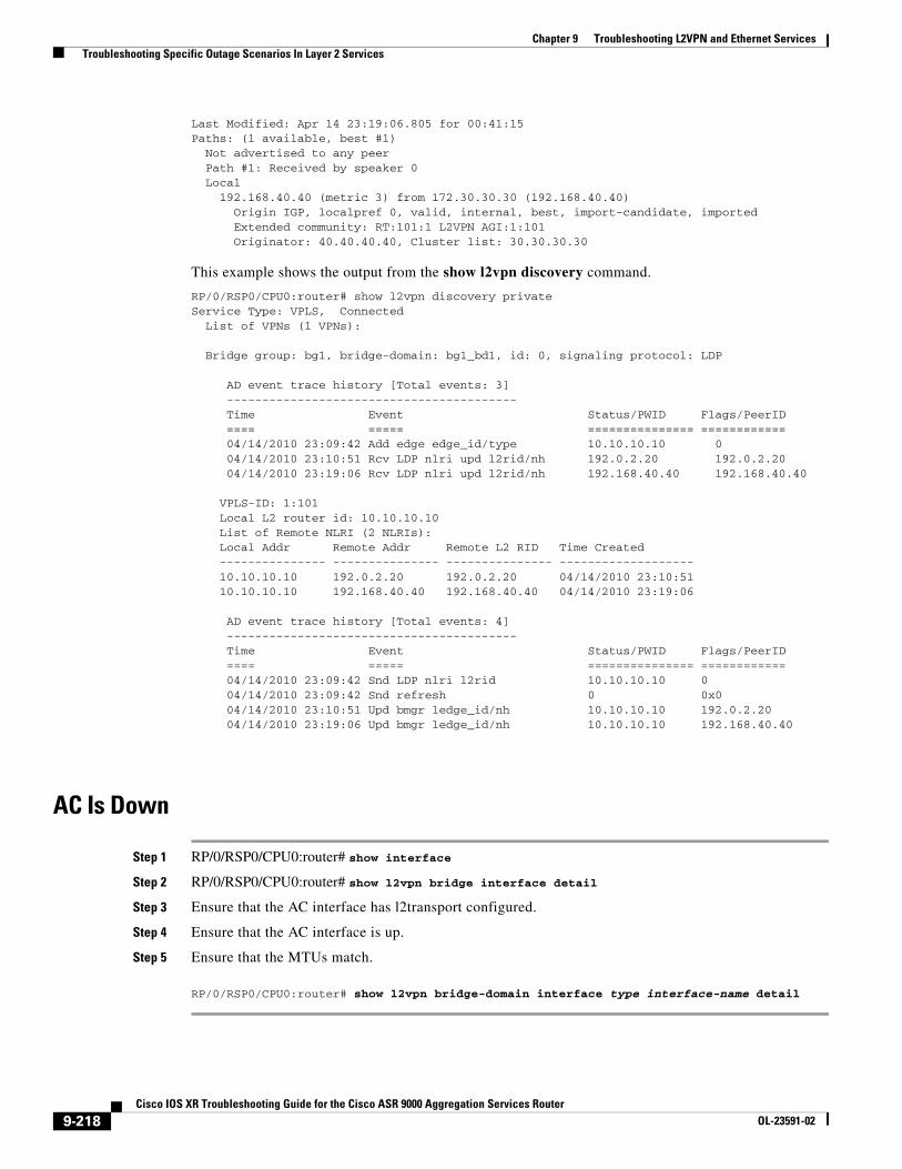
Chapter 9 Troubleshooting L2VPN and Ethernet Services Troubleshooting Specific Outage Scenarios In Layer 2 Services
Last Modified: Apr 14 23:19:06.805 for 00:41:15Paths: (1 available, best #1) Not advertised to any peer Path #1: Received by speaker 0 Local 192.168.40.40 (metric 3) from 172.30.30.30 (192.168.40.40) Origin IGP, localpref 0, valid, internal, best, import-candidate, imported Extended community: RT:101:1 L2VPN AGI:1:101 Originator: 40.40.40.40, Cluster list: 30.30.30.30
This example shows the output from the show l2vpn discovery command.
RP/0/RSP0/CPU0:router# show l2vpn discovery privateService Type: VPLS, Connected List of VPNs (1 VPNs):
Bridge group: bg1, bridge-domain: bg1_bd1, id: 0, signaling protocol: LDP
AD event trace history [Total events: 3] ----------------------------------------- Time Event Status/PWID Flags/PeerID ==== ===== =============== ============ 04/14/2010 23:09:42 Add edge edge_id/type 10.10.10.10 0 04/14/2010 23:10:51 Rcv LDP nlri upd l2rid/nh 192.0.2.20 192.0.2.20 04/14/2010 23:19:06 Rcv LDP nlri upd l2rid/nh 192.168.40.40 192.168.40.40
VPLS-ID: 1:101 Local L2 router id: 10.10.10.10 List of Remote NLRI (2 NLRIs): Local Addr Remote Addr Remote L2 RID Time Created --------------- --------------- --------------- ------------------- 10.10.10.10 192.0.2.20 192.0.2.20 04/14/2010 23:10:51 10.10.10.10 192.168.40.40 192.168.40.40 04/14/2010 23:19:06
AD event trace history [Total events: 4] ----------------------------------------- Time Event Status/PWID Flags/PeerID ==== ===== =============== ============ 04/14/2010 23:09:42 Snd LDP nlri l2rid 10.10.10.10 0 04/14/2010 23:09:42 Snd refresh 0 0x0 04/14/2010 23:10:51 Upd bmgr ledge_id/nh 10.10.10.10 192.0.2.20 04/14/2010 23:19:06 Upd bmgr ledge_id/nh 10.10.10.10 192.168.40.40
AC Is Down
Step 1 RP/0/RSP0/CPU0:router# show interface
Step 2 RP/0/RSP0/CPU0:router# show l2vpn bridge interface detail
Step 3 Ensure that the AC interface has l2transport configured.
Step 4 Ensure that the AC interface is up.
Step 5 Ensure that the MTUs match.
RP/0/RSP0/CPU0:router# show l2vpn bridge-domain interface type interface-name detail
9-218Cisco IOS XR Troubleshooting Guide for the Cisco ASR 9000 Aggregation Services Router
OL-23591-02
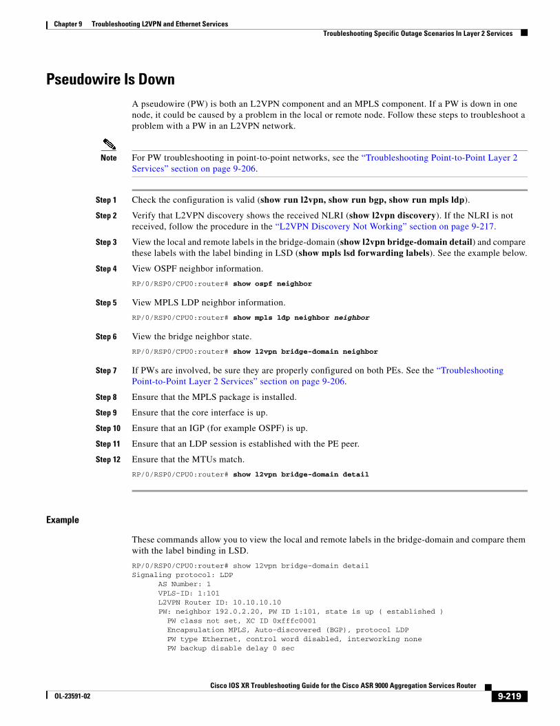
Chapter 9 Troubleshooting L2VPN and Ethernet Services Troubleshooting Specific Outage Scenarios In Layer 2 Services
Pseudowire Is DownA pseudowire (PW) is both an L2VPN component and an MPLS component. If a PW is down in one node, it could be caused by a problem in the local or remote node. Follow these steps to troubleshoot a problem with a PW in an L2VPN network.
Note For PW troubleshooting in point-to-point networks, see the “Troubleshooting Point-to-Point Layer 2 Services” section on page 9-206.
Step 1 Check the configuration is valid (show run l2vpn, show run bgp, show run mpls ldp).
Step 2 Verify that L2VPN discovery shows the received NLRI (show l2vpn discovery). If the NLRI is not received, follow the procedure in the “L2VPN Discovery Not Working” section on page 9-217.
Step 3 View the local and remote labels in the bridge-domain (show l2vpn bridge-domain detail) and compare these labels with the label binding in LSD (show mpls lsd forwarding labels). See the example below.
Step 4 View OSPF neighbor information.
RP/0/RSP0/CPU0:router# show ospf neighbor
Step 5 View MPLS LDP neighbor information.
RP/0/RSP0/CPU0:router# show mpls ldp neighbor neighbor
Step 6 View the bridge neighbor state.
RP/0/RSP0/CPU0:router# show l2vpn bridge-domain neighbor
Step 7 If PWs are involved, be sure they are properly configured on both PEs. See the “Troubleshooting Point-to-Point Layer 2 Services” section on page 9-206.
Step 8 Ensure that the MPLS package is installed.
Step 9 Ensure that the core interface is up.
Step 10 Ensure that an IGP (for example OSPF) is up.
Step 11 Ensure that an LDP session is established with the PE peer.
Step 12 Ensure that the MTUs match.
RP/0/RSP0/CPU0:router# show l2vpn bridge-domain detail
Example
These commands allow you to view the local and remote labels in the bridge-domain and compare them with the label binding in LSD.
RP/0/RSP0/CPU0:router# show l2vpn bridge-domain detailSignaling protocol: LDP AS Number: 1 VPLS-ID: 1:101 L2VPN Router ID: 10.10.10.10 PW: neighbor 192.0.2.20, PW ID 1:101, state is up ( established ) PW class not set, XC ID 0xfffc0001 Encapsulation MPLS, Auto-discovered (BGP), protocol LDP PW type Ethernet, control word disabled, interworking none PW backup disable delay 0 sec
9-219Cisco IOS XR Troubleshooting Guide for the Cisco ASR 9000 Aggregation Services Router
OL-23591-02
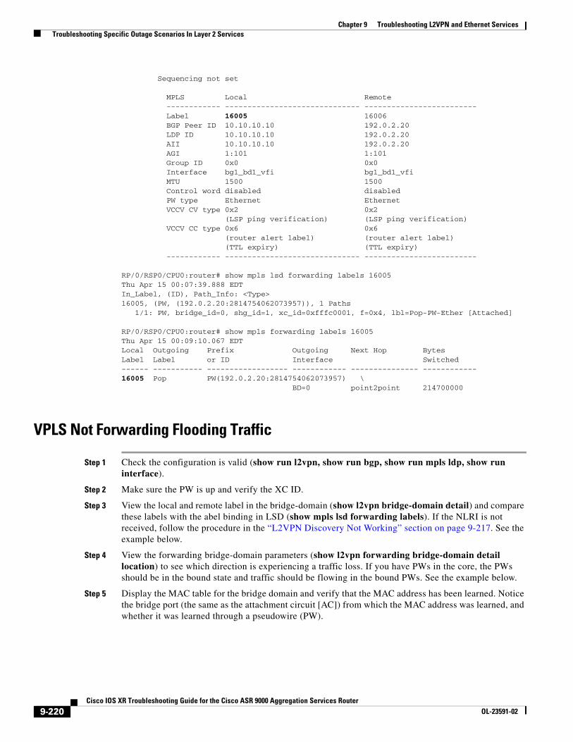
Chapter 9 Troubleshooting L2VPN and Ethernet Services Troubleshooting Specific Outage Scenarios In Layer 2 Services
Sequencing not set
MPLS Local Remote ------------ ------------------------------ ------------------------- Label 16005 16006 BGP Peer ID 10.10.10.10 192.0.2.20 LDP ID 10.10.10.10 192.0.2.20 AII 10.10.10.10 192.0.2.20 AGI 1:101 1:101 Group ID 0x0 0x0 Interface bg1_bd1_vfi bg1_bd1_vfi MTU 1500 1500 Control word disabled disabled PW type Ethernet Ethernet VCCV CV type 0x2 0x2 (LSP ping verification) (LSP ping verification) VCCV CC type 0x6 0x6 (router alert label) (router alert label) (TTL expiry) (TTL expiry) ------------ ------------------------------ -------------------------
RP/0/RSP0/CPU0:router# show mpls lsd forwarding labels 16005Thu Apr 15 00:07:39.888 EDTIn_Label, (ID), Path_Info: <Type>16005, (PW, (192.0.2.20:2814754062073957)), 1 Paths 1/1: PW, bridge_id=0, shg_id=1, xc_id=0xfffc0001, f=0x4, lbl=Pop-PW-Ether [Attached]
RP/0/RSP0/CPU0:router# show mpls forwarding labels 16005 Thu Apr 15 00:09:10.067 EDTLocal Outgoing Prefix Outgoing Next Hop Bytes Label Label or ID Interface Switched ------ ----------- ------------------ ------------ --------------- ------------16005 Pop PW(192.0.2.20:2814754062073957) \ BD=0 point2point 214700000
VPLS Not Forwarding Flooding Traffic
Step 1 Check the configuration is valid (show run l2vpn, show run bgp, show run mpls ldp, show run interface).
Step 2 Make sure the PW is up and verify the XC ID.
Step 3 View the local and remote label in the bridge-domain (show l2vpn bridge-domain detail) and compare these labels with the abel binding in LSD (show mpls lsd forwarding labels). If the NLRI is not received, follow the procedure in the “L2VPN Discovery Not Working” section on page 9-217. See the example below.
Step 4 View the forwarding bridge-domain parameters (show l2vpn forwarding bridge-domain detail location) to see which direction is experiencing a traffic loss. If you have PWs in the core, the PWs should be in the bound state and traffic should be flowing in the bound PWs. See the example below.
Step 5 Display the MAC table for the bridge domain and verify that the MAC address has been learned. Notice the bridge port (the same as the attachment circuit [AC]) from which the MAC address was learned, and whether it was learned through a pseudowire (PW).
9-220Cisco IOS XR Troubleshooting Guide for the Cisco ASR 9000 Aggregation Services Router
OL-23591-02
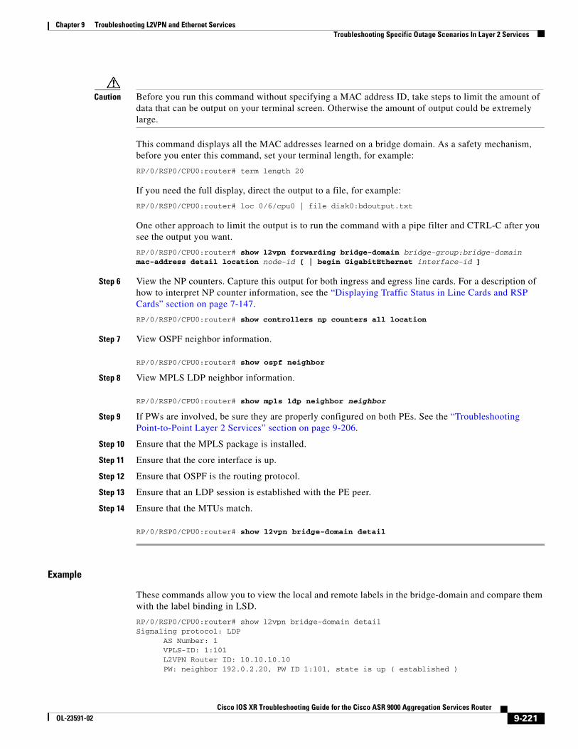
Chapter 9 Troubleshooting L2VPN and Ethernet Services Troubleshooting Specific Outage Scenarios In Layer 2 Services
Caution Before you run this command without specifying a MAC address ID, take steps to limit the amount of data that can be output on your terminal screen. Otherwise the amount of output could be extremely large.
This command displays all the MAC addresses learned on a bridge domain. As a safety mechanism, before you enter this command, set your terminal length, for example:
RP/0/RSP0/CPU0:router# term length 20
If you need the full display, direct the output to a file, for example:
RP/0/RSP0/CPU0:router# loc 0/6/cpu0 | file disk0:bdoutput.txt
One other approach to limit the output is to run the command with a pipe filter and CTRL-C after you see the output you want.
RP/0/RSP0/CPU0:router# show l2vpn forwarding bridge-domain bridge-group:bridge-domain mac-address detail location node-id [ | begin GigabitEthernet interface-id ]
Step 6 View the NP counters. Capture this output for both ingress and egress line cards. For a description of how to interpret NP counter information, see the “Displaying Traffic Status in Line Cards and RSP Cards” section on page 7-147.
RP/0/RSP0/CPU0:router# show controllers np counters all location
Step 7 View OSPF neighbor information.
RP/0/RSP0/CPU0:router# show ospf neighbor
Step 8 View MPLS LDP neighbor information.
RP/0/RSP0/CPU0:router# show mpls ldp neighbor neighbor
Step 9 If PWs are involved, be sure they are properly configured on both PEs. See the “Troubleshooting Point-to-Point Layer 2 Services” section on page 9-206.
Step 10 Ensure that the MPLS package is installed.
Step 11 Ensure that the core interface is up.
Step 12 Ensure that OSPF is the routing protocol.
Step 13 Ensure that an LDP session is established with the PE peer.
Step 14 Ensure that the MTUs match.
RP/0/RSP0/CPU0:router# show l2vpn bridge-domain detail
Example
These commands allow you to view the local and remote labels in the bridge-domain and compare them with the label binding in LSD.
RP/0/RSP0/CPU0:router# show l2vpn bridge-domain detailSignaling protocol: LDP AS Number: 1 VPLS-ID: 1:101 L2VPN Router ID: 10.10.10.10 PW: neighbor 192.0.2.20, PW ID 1:101, state is up ( established )
9-221Cisco IOS XR Troubleshooting Guide for the Cisco ASR 9000 Aggregation Services Router
OL-23591-02
Chapter 9 Troubleshooting L2VPN and Ethernet Services Troubleshooting Specific Outage Scenarios In Layer 2 Services
PW class not set, XC ID 0xfffc0001 Encapsulation MPLS, Auto-discovered (BGP), protocol LDP PW type Ethernet, control word disabled, interworking none PW backup disable delay 0 sec Sequencing not set
MPLS Local Remote ------------ ------------------------------ ------------------------- Label 16005 16006 BGP Peer ID 10.10.10.10 192.0.2.20 LDP ID 10.10.10.10 192.0.2.20 AII 10.10.10.10 192.0.2.20 AGI 1:101 1:101 Group ID 0x0 0x0 Interface bg1_bd1_vfi bg1_bd1_vfi MTU 1500 1500 Control word disabled disabled PW type Ethernet Ethernet VCCV CV type 0x2 0x2 (LSP ping verification) (LSP ping verification) VCCV CC type 0x6 0x6 (router alert label) (router alert label) (TTL expiry) (TTL expiry) ------------ ------------------------------ -------------------------
RP/0/RSP0/CPU0:router# show mpls lsd forwarding labels 16005Thu Apr 15 00:07:39.888 EDTIn_Label, (ID), Path_Info: <Type>16005, (PW, (192.0.2.20:2814754062073957)), 1 Paths 1/1: PW, bridge_id=0, shg_id=1, xc_id=0xfffc0001, f=0x4, lbl=Pop-PW-Ether [Attached]
RP/0/RSP0/CPU0:router# show mpls forwarding labels 16005 Thu Apr 15 00:09:10.067 EDTLocal Outgoing Prefix Outgoing Next Hop Bytes Label Label or ID Interface Switched ------ ----------- ------------------ ------------ --------------- ------------16005 Pop PW(192.0.2.20:2814754062073957) \ BD=0 point2point 214700000
RP/0/RSP0/CPU0:router# show l2vpn forwarding bridge-domain detail location 0/6/CPU0Fri Jan 7 13:54:45.740 PST
Bridge-domain name: 189:189, id: 0, state: up MAC learning: enabled MAC port down flush: enabled Flooding: Broadcast & Multicast: enabled Unknown unicast: enabled MAC aging time: 300 s, Type: inactivity MAC limit: 4000, Action: none, Notification: syslog MAC limit reached: no MAC Secure: disabled, Logging: disabled DHCPv4 snooping: profile not known on this node Dynamic ARP Inspection: disabled, Logging: disabled IP Source Guard: disabled, Logging: disabled IGMP snooping: disabled, flooding: enabled Bridge MTU: 9000 bytes Number of bridge ports: 2 Number of MAC addresses: 2 Multi-spanning tree instance: 0
GigabitEthernet0/1/0/3.189, state: oper up Number of MAC: 2
9-222Cisco IOS XR Troubleshooting Guide for the Cisco ASR 9000 Aggregation Services Router
OL-23591-02
Chapter 9 Troubleshooting L2VPN and Ethernet Services Troubleshooting Specific Outage Scenarios In Layer 2 Services
Statistics: packets: received 0, sent 0 bytes: received 0, sent 0 Storm control drop counters: packets: broadcast 0, multicast 0, unknown unicast 0 bytes: broadcast 0, multicast 0, unknown unicast 0 Dynamic arp inspection drop counters: packets: 0, bytes: 0 IP source guard drop counters: packets: 0, bytes: 0 ...
RP/0/RSP0/CPU0:router# show controllers np counters all Mon Nov 15 12:20:35.289 EST
Node: 0/0/CPU0:----------------------------------------------------------------Show global stats counters for NP0, revision v3
Read 20 non-zero NP counters:Offset Counter FrameValue Rate (pps)------------------------------------------------------------------------------- 23 PARSE_FABRIC_RECEIVE_CNT 417 0 30 RESOLVE_INRESS_DROP_CNT 9 0
31 RESOLVE_EGRESS_DROP_CNT 6 053 MODIFY_FRAMES_PADDED_CNT 3230 0
67 PARSE_MOFRR_SWITCH_MSG_RCVD_FROM_FAB 920 0 70 RESOLVE_INGRESS_L2_PUNT_CNT 1081 0 71 RESOLVE_EGRESS_L3_PUNT_CNT 4613 0 74 RESOLVE_LEARN_FROM_NOTIFY_CNT 3484 0 75 RESOLVE_BD_FLUSH_DELETE_CNT 104 0 83 RESOLVE_MOFRR_HASH_UPDATE_CNT 463 0 87 RESOLVE_MOFRR_SWITCH_MSG_INGNORED 407 0 111 DIAGS 536 0295 DROP_IPV4_NEXT_HOP_DOWN 15 0
.
.
.
The following command allows you to view the bridge domain forwarding data.
RP/0/RSP0/CPU0:router# show l2vpn forwarding bridge-domain location 0/6/CPU0 Thu Apr 15 00:15:29.581 EDT Bridge MACBridge-Domain Name ID Ports addr Flooding Learning State -------------------------------- ------ ----- ------ -------- -------- ---------bg1:bg1_bd1 0 3 4 Enabled Enabled UP
The following command allows you to view the bridge domain MAC details. The output from this command can be very large, so you should limit the terminal screen output or send the data to a file.
RP/0/RSP0/CPU0:router# loc 0/6/cpu0 | file disk0:bdoutput.txt
RP/0/RSP0/CPU0:router# show l2vpn forwarding bridge-domain mac-address location 0/6/CPU0Mac Address Type Learned from/Filtered on LC learned Resync Age Mapped to --------------------------------------------------------------------------------0000.0001.0101 dynamic Gi0/6/0/1.1 0/6/CPU0 0d 0h 1m 59s N/A 0000.0001.0102 dynamic Gi0/6/0/1.1 0/6/CPU0 0d 0h 1m 59s N/A 0000.0002.0202 dynamic (192.0.2.20, 1:101) 0/6/CPU0 0d 0h 1m 59s N/A 0000.0003.0303 dynamic (192.168.40.40, 1:101) 0/6/CPU0 0d 0h 1m 59s N/A
9-223Cisco IOS XR Troubleshooting Guide for the Cisco ASR 9000 Aggregation Services Router
OL-23591-02
Chapter 9 Troubleshooting L2VPN and Ethernet Services Troubleshooting Specific Outage Scenarios In Layer 2 Services
VPLS Not Forwarding Flooding Traffic from AC to Pseudowire
Step 1 View ingress UIDB and XID for the segment.
RP/0/RSP0/CPU0:router# show l2vpn forwarding interface hardware ingress detail location
Step 2 If PWs are invloved, view PW hardware information.
RP/0/RSP0/CPU0:router# show l2vpn forwarding neighbor 192.168.12.5 pw-id 100 hardware egress location node-id0
Step 3 View MPLS leaf information.
RP/0/RSP0/CPU0:router# show mpls forwarding labels hardware egress detail location
Step 4 View bridge information about Broadcast, Multicast and Unknown Unicast.
RP/0/RSP0/CPU0:router# show l2vpn bridge-domain bd-name 1 det
Step 5 Ensure that the MAC limit has not been exceeded.
RP/0/RSP0/CPU0:router# show l2vpn forwarding bridge-domain 1:1 detail location
Step 6 View PI event traces.
RP/0/RSP0/CPU0:router# show l2vpn trace location
Step 7 Ensure that the pseudowires (as applicable) and AC are up.
Step 8 Verify the hardware is programmed for both ACs.
Step 9 RP/0/RSP0/CPU0:router# show l2vpn forwarding interface GigabitEtherne0/5/0/2 hardware ingress detail location node-id
Step 10 Verify the hardware is programmed for pseudowires.
VPLS Not Forwarding Flooding Traffic from Pseudowire to AC
Step 1 View ingress UIDB and XID for the segment.
RP/0/RSP0/CPU0:router# show l2vpn forwarding interface hardware ingress detail location
Step 2 View MPLS leaf information.
RP/0/RSP0/CPU0:router# show mpls forwarding labels hardware egress detail location
Step 3 View bridge information about Broadcast, Multicast and Unknown Unicast.
RP/0/RSP0/CPU0:router# show l2vpn bridge-domain bd-name 1 det
Step 4 Ensure that the MAC limit has not been exceeded.
RP/0/RSP0/CPU0:router# show l2vpn forwarding bridge-domain 1:1 detail location
Step 5 View PI event traces.
RP/0/RSP0/CPU0:router# show l2vpn trace location
9-224Cisco IOS XR Troubleshooting Guide for the Cisco ASR 9000 Aggregation Services Router
OL-23591-02
Chapter 9 Troubleshooting L2VPN and Ethernet Services Troubleshooting Specific Outage Scenarios In Layer 2 Services
Step 6 Ensure that the pseudowires (as applicable) and AC are up.
Step 7 Verify that the hardware is programmed for both ACs.
RP/0/RSP0/CPU0:router# show l2vpn forwarding interface GigabitEtherne0/5/0/2 hardware ingress detail location node-id
Step 8 Verify that the hardware is programmed for PW (if applicable).
VPLS Not Forwarding Unicast Traffic from AC to AC
Step 1 View the bridge domain state.
RP/0/RSP0/CPU0:router# show l2vpn bridge-domain bd-name bd-name-id detail
Step 2 Ensure that the hardware is programmed for both ACs.
Step 3 Ensure that the destination MAC entry is programmed for the LC’s destination interface.
RP/0/RSP0/CPU0:router# show l2vpn forwarding bridge-domain mac-address location node-id
VPLS Not Forwarding Unicast Traffic from AC to Pseudowire
Step 1 View the bridge domain state.
RP/0/RSP0/CPU0:router# show l2vpn bridge-domain bd-name bd-name-id detail
Step 2 Ensure that the hardware is programmed for both AC and PW (as applicable).
Step 3 Ensure that the destination MAC entry is programmed for the LC’s destination interface.
RP/0/RSP0/CPU0:router# show l2vpn forwarding bridge-domain mac-address location node-id
VPLS Not Forwarding Flooding Traffic from Pseudowire to AC
Step 1 View the bridge domain state.
RP/0/RSP0/CPU0:router# show l2vpn bridge-domain bd-name bd-name-id detail
Step 2 Ensure that the hardware is programmed for both AC and PW (as applicable).
9-225Cisco IOS XR Troubleshooting Guide for the Cisco ASR 9000 Aggregation Services Router
OL-23591-02
Chapter 9 Troubleshooting L2VPN and Ethernet Services Troubleshooting Specific Outage Scenarios In Layer 2 Services
Pseudowire Up but Ping Fails
Step 1 Determine where the ping packets are being dropped, view the xconnect AC interface counters and the L2VPN counters for the PW. For information on ping procedures, see the “Troubleshooting Ping and ARP Connectivity” section on page 3-75.
Step 2 View the bridge domain state.
RP/0/RSP0/CPU0:router# show l2vpn bridge-domain bd-name bd-name-id detail
Step 3 Ensure that both CEs are on the same subnet.
Step 4 Ensure that the MTUs match.
Step 5 Ensure that the end-to-end encapsulations match.
Traffic Loss
Step 1 Determine where the packets are being dropped, view the xconnect AC interface counters and the L2VPN counters for the PW. For information on ping procedures, see the “Troubleshooting Ping and ARP Connectivity” section on page 3-75.
Step 2 View the bridge domain state.
RP/0/RSP0/CPU0:router# show l2vpn bridge-domain bd-name bd-name-id detail
Step 3 View segment counters to see if the packet and byte switched count increased.
RP/0/RSP0/CPU0:router# show l2vpn forwarding interface GigabitEthernet interface-id detail location node-id
Step 4 Ensure that the bandwidth rates match between the CEs.
Pseudowire Flap Causing Traffic Loss
Step 1 View the bridge domain state.
RP/0/RSP0/CPU0:router# show l2vpn bridge-domain bd-name bd-name-id detail
Step 2 View segment counters to see if the packet and byte switched count increased.
RP/0/RSP0/CPU0:router# show l2vpn forwarding interface GigabitEthernet interface-id detail location node-id
Step 3 View PI event traces.
RP/0/RSP0/CPU0:router# show l2vpn trace location
9-226Cisco IOS XR Troubleshooting Guide for the Cisco ASR 9000 Aggregation Services Router
OL-23591-02
Chapter 9 Troubleshooting L2VPN and Ethernet Services Troubleshooting Dynamic Host Configuration Protocol Snooping
Traffic Loss During RSP Fail Over
Step 1 View the state of the xconnect.
RP/0/RSP0/CPU0:router# show l2vpn bridge detail
Step 2 View the counter for the segment.
RP/0/RSP0/CPU0:router# show l2vpn forwarding interface GigabitEthernet interface-id detail location node-id
Step 3 View the state of the bridge domain.
RP/0/RSP0/CPU0:router# show l2vpn bridge-domain bd-name bd-name-id detail
Step 4 View ingress UIDB.
RP/0/RSP0/CPU0:router# show l2vpn forwarding interface interface hardware ingress detail
location node-id
Step 5 Check all routers in the MPLS path to ensure the following are configured:
a. MPLS LDP graceful restart
b. OSPF NSF
Step 6 View the segment counters to see if the packet and byte switched count increased.
RP/0/RSP0/CPU0:router# show l2vpn forwarding interface GigabitEthernet node-id detail
location node-id
Preferred Path Not Working
Step 1 View the state of the bridge domain.
RP/0/RSP0/CPU0:router# show l2vpn bridge-domain bd-name bd-name-id detail
Step 2 View ingress UIDB.
RP/0/RSP0/CPU0:router# show l2vpn forwarding interface interface hardware ingress detail
location node-id
Troubleshooting Dynamic Host Configuration Protocol SnoopingDynamic Host Configuration Protocol Snooping (DHCP snooping) provides DHCP security by filtering untrusted DHCP messages, and by building and maintaining a DHCP snooping binding table. An untrusted message is a message that is received from outside the network or firewall and that can cause traffic attacks within your network. This section describes the following commands:
• Show Commands, page 9-228
9-227Cisco IOS XR Troubleshooting Guide for the Cisco ASR 9000 Aggregation Services Router
OL-23591-02
Chapter 9 Troubleshooting L2VPN and Ethernet Services Troubleshooting Dynamic Host Configuration Protocol Snooping
• Trace Commands, page 9-228
• Syslog Commands, page 9-228
• Tech-support Commands, page 9-229
• Action Commands, page 9-229
• L2VPN Commands, page 9-229
• L2Snoop Commands, page 9-229
• Interface Controller Commands, page 9-230
Show CommandsThe DHCP application runs on the RSP. It has several EXEC mode CLI show commands that present the application's configuration state, DHCP client state, and DHCP packet statistics.
• show dhcp ipv4 snoop binding—View the state of DHCP clients in a table.
• show dhcp ipv4 snoop binding mac-address macaddress—View detailed state of DHCP Clients with the specified MAC Address.
• show dhcp ipv4 snoop binding summary—View the total number of DHCP Clients.
• show dhcp ipv4 snoop profile—View a list of DHCP snoop profiles.
• show dhcp ipv4 snoop profile name name—View details of a specific DHCP snoop profile.
• show dhcp ipv4 snoop statistics—View aggregate DHCP snoop Rx, Tx, and drop packets for each bridge domain.
• show dhcp ipv4 snoop statistics bridge-domain name—View detailed DHCP snoop Rx, Tx, and drop packets for each message type in a bridge domain.
Trace CommandsThe DHCP application has over 1200 Trace logs. The Trace logs record significant events that occur in the application. Trace logs that are associated with a specific DHCP client will contain the client MAC address.
• show dhcp ipv4 trace errors—View error traces.
• show dhcp ipv4 trace events—View event traces.
• show dhcp ipv4 trace packets—View packet processing traces.
• show dhcp ipv4 trace snoop errors—View error traces for DHCP snoop feature.
• show dhcp ipv4 trace snoop events—View event traces for the DHCP snoop feature.
• show dhcp ipv4 trace snoop internal—View internal debug traces for the DHCP snoop feature.
Syslog CommandsThe DHCP application has over 1600 syslog logs. These logs record events that occur in the application.
• debug dhcp ipv4 errors—View error logs.
• debug dhcp ipv4 events—View event logs.
9-228Cisco IOS XR Troubleshooting Guide for the Cisco ASR 9000 Aggregation Services Router
OL-23591-02
Chapter 9 Troubleshooting L2VPN and Ethernet Services Troubleshooting Dynamic Host Configuration Protocol Snooping
• debug dhcp ipv4 packet—View packet processing logs.
• debug dhcp ipv4 snoop errors—View error logs for DHCP snoop feature.
• debug dhcp ipv4 snoop events—View event logs for the DHCP snoop feature.
• debug dhcp ipv4 snoop internal—View internal debug logs for the DHCP snoop feature.
Tech-support CommandsThe DHCP application has four tech-support commands that call groups of DHCP CLI commands. Use tech-support commands for information about the DHCP application for debugging.
• show tech-support dhcp ipv4 snoop file filename
• show tech-support dhcp ipv4 snoop bridge-domain-name bridge-domain-id file filename—View information for the specified bridge domain.
• show tech-support dhcp ipv4 snoop profile-name profilename file filename—View information for the specified profile.
Action CommandsUse the following CLI commands to clear DHCP snoop binding states:
• clear dhcp ipv4 snoop binding—Clears all DHCP snoop client bindings.
• clear dhcp ipv4 snoop binding bridge-domain bridge-domain-name—Clears all DHCP snoop client bindings in the specified bridge domain.
• clear dhcp ipv4 snoop binding mac-address macaddress—Clears the DHCP snoop client bindings with the specified MAC address.
L2VPN Commands DHCP snoop is enabled on L2VPN ACs by attaching a DHCP snoop profile to a bridge domain or AC. The DHCP snoop trusted attribute is configured on an AC according to the value of the trusted attribute in the DHCP snoop profile. L2VPN CLI commands are used to display the status of DHCP snoop attributes on L2VPN bridge domains and ACs.
• show l2vpn bridge-domain bd-name bridgename detail—View the L2VPN DHCP snoop configuration for the specified bridge domain.
• show l2vpn forwarding interface interface detail location location—View the L2VPN DHCP snoop configuration for a specific interface.
L2Snoop CommandsL2Snoop receives and transmits DHCP snoop packets between NETIO and the DHCP snoop application on the RSP.
show l2snoop statistics pcb all—View the L2SNOOP DHCP packet Rx/Tx statistics to and from the DHCP snoop application on the RSP.
9-229Cisco IOS XR Troubleshooting Guide for the Cisco ASR 9000 Aggregation Services Router
OL-23591-02
Chapter 9 Troubleshooting L2VPN and Ethernet Services Troubleshooting Multiple Spanning Tree
Interface Controller CommandsInterface controllers receive and send DHCP snoop packets between the wire and the network processors.
show controllers interface stats—View the interface controller statistics that include DHCP packets that are sent and received from the wire.
Troubleshooting Multiple Spanning TreeMultiple Spanning Tree (MST) is an IEEE standard based on the Cisco proprietary Multiple Instances Spanning Tree Protocol (MISTP) implementation. This section explains how to troubleshoot MST and contains the following subsections:
• Using show and debug Commands, page 9-230
• MSTP Incorrectly or Inconsistently Formed, page 9-230
• MSTP Correctly Formed, but Traffic Flooding, page 9-231
• Packet Forwarding Does Not Match MSTP State, page 9-231
• MSTAG Access Network Does Not Recognize MSTAG Node as Root, page 9-231
• Traffic Not Switching Through MSTAG Node(s), page 9-232
Using show and debug CommandsFor a complete list of MST show and debug commands, see the “Multiple Spanning Tree Protocol Commands” chapter in the “Cisco ASR 9000 Series Aggregation Services Router L2VPN and Ethernet Services Command Reference” module.
MSTP Incorrectly or Inconsistently FormedWhen the spanning tree is misformed, it is often because of misconfiguration or BPDU loss. This generally manifests as more than one node showing itself as ROOT, but can also result in disagreement on which nodes are ROOT.
MSTP Incorrectly or Inconsistently Formed—Misconfiguration
Ensure that the following match on the nodes:
• Configuration name
• Bridge revision
• Provider-bridge mode
• Instance to VLAN mapping
Run the following command to check that the configuration is consistent across multiple devices.
RP/0/RSP0/CPU0:router# show spanning-tree mst protocol-instance-id configuration
9-230Cisco IOS XR Troubleshooting Guide for the Cisco ASR 9000 Aggregation Services Router
OL-23591-02
Chapter 9 Troubleshooting L2VPN and Ethernet Services Troubleshooting Multiple Spanning Tree
MSTP Incorrectly or Inconsistently Formed—BPDU Loss
Determine if node A is sending BPDUs to node B. The output of the following command includes a count of the number of BDPUs being sent and received. Run the command several times for each interface connecting the nodes.
RP/0/RSP0/CPU0:router# show spanning-tree mst protocol-instance-id interface interface-name
Only designated ports will send periodic BPDUs, but non-designated ports send updates on topology changes and startup. Ensure that BPDUs sent and received are going up as appropriate.
MSTP Correctly Formed, but Traffic FloodingIntermittent BPDU loss may mean the spanning tree will not show up incorrectly in the show commands, but will send out topology change notifications. These notifications cause a MAC flush, forcing traffic to flood until the MAC addresses are re-learned.
Run the following commend to check whether there have been any flushes.
RP/0/RSP0/CPU0:router# show spanning-tree mst <protocol-instance> topology-change flushes
Look for topology change notifications. Run the following command and look for TC 1:
Note This option is verbose.
Packet Forwarding Does Not Match MSTP State
Step 1 Shut down redundant links, remove MSTP configuration, and ensure that basic bridging works.
RP/0/RSP0/CPU0:router# show spanning-tree mst name
RP/0/RSP0/CPU0:router# show interface interface-name
Step 2 Check the state of each port as calculated by MSTP, and compare it with packet transmit and receive counts on ports and Ethernet flow points (EFPs) that are controlled by MSTP. Normal data packets should be sent/received only on ports that are in forwarding (FWD) state. In steady state operation, BPDUs are sent if there is at least one MSTI that is in Designated role.
Step 3 Ensure that BPDUs are flowing and that root bridge selection is correct. Check those related scenarios first.
RP/0/RSP0/CPU0:router# show l2vpn bridge-domain [detail]
This command will show the status of members of the bridge domain. Ensure that the relevant bridge domain members are up.
Step 4 Check forwarding state as programmed in hardware.
MSTAG Access Network Does Not Recognize MSTAG Node as RootIf multiple spanning tree access gateway (MSTAG) is not recognized as root, check that the two MSTAG devices are configured with the same root-id and root-priority for every MST instance (MSTI), and that the root-priority is lower than any of the access devices (preferably 0).
Also check (on the access devices) for any disputes; disputes are an indication of a misconfiguration.
9-231Cisco IOS XR Troubleshooting Guide for the Cisco ASR 9000 Aggregation Services Router
OL-23591-02
Chapter 9 Troubleshooting L2VPN and Ethernet Services Additional References—Command Reference and Configuration Guides
Step 1 To view the BPDUs being sent by MSTAG, run the following command.
RP/0/RSP0/CPU0:router# show spanning-tree mstag protocol-instance-id bpdu interface interface-name
There are two ways of configuring MSTAG:
• Advertise as though both nodes are separate—requires each node have a unique bridge id and the configurations complement each other.
• Advertise as though each node is a different port on the same node—configuration is identical except for the port id.
Commands for MSTAG must target the untagged EFP instead of the base interface. Perform the following steps to verify your configuration and debug MSTAG.
Step 2 Verify the running configuration.
RP/0/RSP0/CPU0:router# show running-config spanning-tree {mst | mstag | repag} name
Traffic Not Switching Through MSTAG Node(s)
Step 1 Collect L2VPN and UIDB data to verify the data path is healthy.
RP/0/RSP0/CPU0:router# show l2vpn bridge-domain [detail]
Step 2 Ensure that the forwarding state is set as it was programmed in the hardware.
Additional References—Command Reference and Configuration Guides
The following documents provide information on the commands and configuration procedures for L2VPN and Ethernet Services:
• Cisco ASR 9000 Series Aggregation Services Router L2VPN and Ethernet Services Command Reference
• Cisco ASR 9000 Series Aggregation Services Router L2VPN and Ethernet Services Configuration Guide
Use the following guide when you configure routing. L2VPN services rely on Layer 3 connectivity from the provider edge (PE) through the core:
Cisco ASR 9000 Series Aggregation Services Router Routing Configuration Guide, Release 4.0
9-232Cisco IOS XR Troubleshooting Guide for the Cisco ASR 9000 Aggregation Services Router
OL-23591-02