Embed Size (px)
Citation preview
Cisco XR 12410 and CiscOL-17441-01
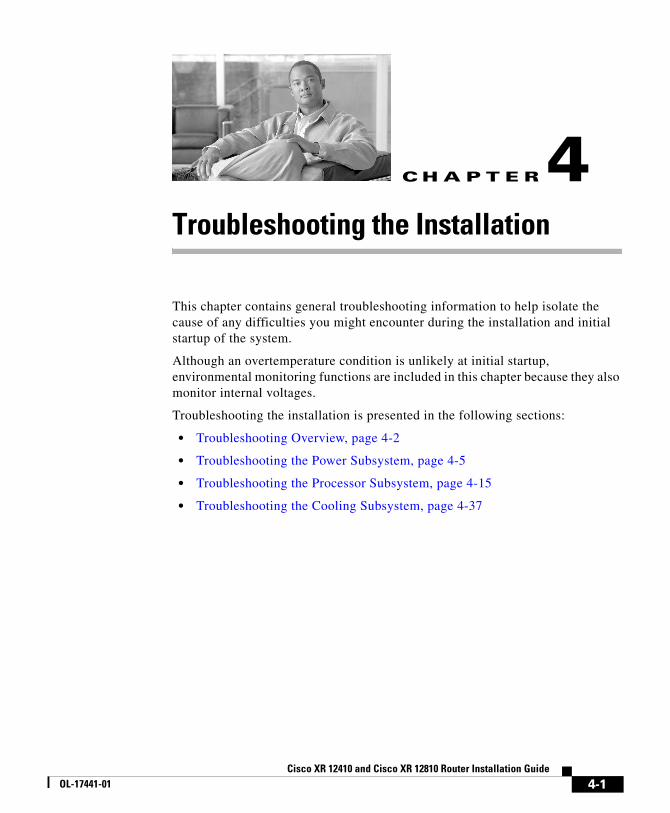
C H A P T E R 4
Troubleshooting the InstallationThis chapter contains general troubleshooting information to help isolate the cause of any difficulties you might encounter during the installation and initial startup of the system.
Although an overtemperature condition is unlikely at initial startup, environmental monitoring functions are included in this chapter because they also monitor internal voltages.
Troubleshooting the installation is presented in the following sections:
• Troubleshooting Overview, page 4-2
• Troubleshooting the Power Subsystem, page 4-5
• Troubleshooting the Processor Subsystem, page 4-15
• Troubleshooting the Cooling Subsystem, page 4-37
4-1o XR 12810 Router Installation Guide
Chapter 4 Troubleshooting the InstallationTroubleshooting Overview
Troubleshooting OverviewThis section describes the methods used in troubleshooting the router. The troubleshooting methods are organized according to the major subsystems in the router.
If you are unable to solve a problem on your own, you can contact a Cisco customer service representative for assistance. When you call, have the following information ready:
• Date you received the router and the chassis serial number (located on a label on the back of the chassis).
• Installed line cards.
– Use the show hardware command to determine which line cards are installed if possible.
• Cisco software release number.
– Use the show version command to determine this information if possible.
• Brief description of the symptoms and steps you have taken to isolate and solve the issue.
• Maintenance agreement or warranty information.
Troubleshooting Using a Subsystem ApproachTo solve a system problem, try to isolate the problem to a specific subsystem. Compare current router behavior with expected router behavior. Because a startup issue is usually attributable to one component, it is most efficient to examine each subsystem, rather than trying to troubleshoot each router component.
For troubleshooting purposes in this chapter, the router consists of the following subsystems:
• Power subsystem—Includes the following components:
– AC-input or DC-input power supplies, also called power entry modules (PEMs). The router chassis is shipped with fully-redundant PEMs installed in the chassis.
4-2Cisco XR 12410 and Cisco XR 12810 Router Installation Guide
OL-17441-01
Chapter 4 Troubleshooting the InstallationTroubleshooting Overview
• Chassis backplane power distribution. –48 VDC power from the power supplies is transferred to the chassis backplane and is distributed to all of the cards through the backplane connectors. The blower module receives power from the chassis backplane through a wiring harness and passes MBus data back to the chassis backplane.
• Processor subsystem—Includes the RP, up to nine line cards (when no optional, redundant RP is installed), and two alarm cards. The RP and line cards are equipped with onboard processors. The RP downloads a copy of the Cisco software image to each line card processor. The system uses an alphanumeric display (on each line card and RP) t o display status and error messages, which can help in troubleshooting.
• Cooling subsystem—Consists of a blower module, which circulates air through the card cages to cool the cards, and a fan in each of the power modules, which circulates cooling air through the power module.
Normal Router Startup SequenceYou can generally determine when and where the router failed during the startup sequence by checking the status LEDs on the power modules, and the alphanumeric displays on the RP and line cards.
In a normal router startup sequence, the following sequence of events and conditions occur:
1. The fans in the blower module receive power and begin drawing air through the chassis.
The blower module OK indicator is on.
2. The fan in each PEM receives power and begins drawing air through the power supply.
The power supply Pwr OK indicator is on.
3. As the power on and boot process progresses for the RP and each installed line card, the status of each card appears on the alphanumeric display on the front panel of the card:
– The upper row of the display is powered by the DC-to-DC converter on the card.
– The lower row of the display is powered by the +5 VDC provided through the backplane.
4-3Cisco XR 12410 and Cisco XR 12810 Router Installation Guide
OL-17441-01
Chapter 4 Troubleshooting the InstallationTroubleshooting Overview
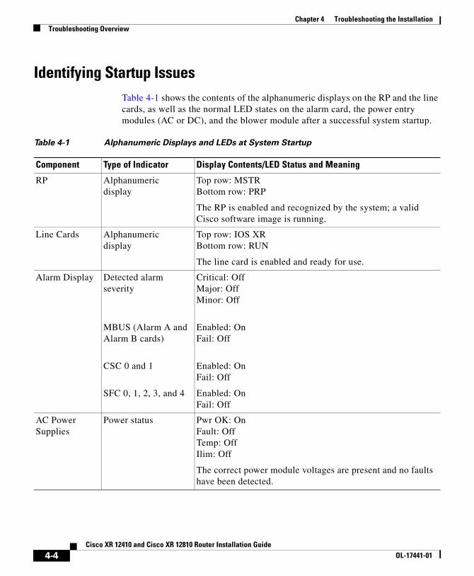
Identifying Startup IssuesTable 4-1 shows the contents of the alphanumeric displays on the RP and the line cards, as well as the normal LED states on the alarm card, the power entry modules (AC or DC), and the blower module after a successful system startup.
Table 4-1 Alphanumeric Displays and LEDs at System Startup
Component Type of Indicator Display Contents/LED Status and Meaning
RP Alphanumeric display
Top row: MSTRBottom row: PRP
The RP is enabled and recognized by the system; a valid Cisco software image is running.
Line Cards Alphanumeric display
Top row: IOS XRBottom row: RUN
The line card is enabled and ready for use.
Alarm Display Detected alarm severity
MBUS (Alarm A and Alarm B cards)
CSC 0 and 1
SFC 0, 1, 2, 3, and 4
Critical: OffMajor: OffMinor: Off
Enabled: OnFail: Off
Enabled: OnFail: Off
Enabled: OnFail: Off
AC Power Supplies
Power status Pwr OK: OnFault: OffTemp: OffIlim: Off
The correct power module voltages are present and no faults have been detected.
4-4Cisco XR 12410 and Cisco XR 12810 Router Installation Guide
OL-17441-01
Chapter 4 Troubleshooting the InstallationTroubleshooting the Power Subsystem
Troubleshooting the Power SubsystemThis section contains information to troubleshoot the power subsystems:
• Troubleshooting the AC-Input Power Subsystem, page 4-5
• Troubleshooting the DC-Input Power Subsystem, page 4-8
• Troubleshooting the Power Distribution System, page 4-14
Troubleshooting the AC-Input Power SubsystemAC-input power supplies are monitored for internal temperature, voltage, and current load by the MBus module on the alarm cards, and by the master MBus module on the RP. If the router detects an extreme condition, it generates an alarm on the alarm card and logs the appropriate warning messages on the console.
DC Power Supplies
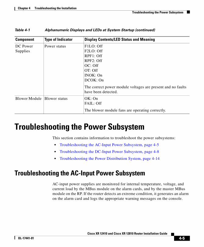
Power status F1LO: OffF2LO: OffRPF1: OffRPF2: OffOC: OffOT: OffINOK: OnDCOK: On
The correct power module voltages are present and no faults have been detected.
Blower Module Blower status OK: OnFAIL: Off
The blower module fans are operating correctly.
Table 4-1 Alphanumeric Displays and LEDs at System Startup (continued)
Component Type of Indicator Display Contents/LED Status and Meaning
4-5Cisco XR 12410 and Cisco XR 12810 Router Installation Guide
OL-17441-01
Chapter 4 Troubleshooting the InstallationTroubleshooting the Power Subsystem
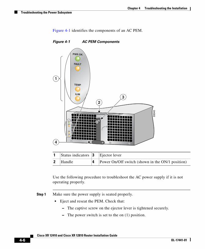
Figure 4-1 identifies the components of an AC PEM.
Figure 4-1 AC PEM Components
Use the following procedure to troubleshoot the AC power supply if it is not operating properly.
Step 1 Make sure the power supply is seated properly.
• Eject and reseat the PEM. Check that:
– The captive screw on the ejector lever is tightened securely.
– The power switch is set to the on (1) position.
1 Status indicators 3 Ejector lever
2 Handle 4 Power On/Off switch (shown in the ON/1 position)
0
PWR OK
FAULT
TEMP
ILIM
PWR OK
FAULT
TEMP
ILIM
9304
0
4
2
1
3
4-6Cisco XR 12410 and Cisco XR 12810 Router Installation Guide
OL-17441-01
Chapter 4 Troubleshooting the InstallationTroubleshooting the Power Subsystem
Step 2 Make sure the router is powered on and that all power cords are connected properly. Check that the:
• Power cords on the horizontal trough on the back of the chassis are secured in place with their retention clips.
• Power cords at the power source end are securely plugged into their own AC power outlet.
• Source AC circuit breaker is switched on.
Step 3 Check the power supply status LED indicators.
• Pwr OK (green)—Indicates that the power supply is operating normally, and both the source AC input voltage of 200 VAC to 240 VAC, and the –48 VDC output voltage to the backplane are within the nominal operating range. This indicator lights when the power switch is set to the on (1) position.
– If the Pwr OK indicator remains off after checking all of the power sources, replace the power supply with a spare.
– If the spare power supply does not work, replace its power distribution unit (PDU).
• Fault (yellow)—Indicates that the system has detected a fault within the power supply. This indicator remains off during normal operation.
If the indicator is on:
– Toggle the power switch off and then on. If the indicator remains on after several attempts to power it on, replace the power supply with a spare.
– If the spare power supply also fails, the problem could be a faulty power shelf backplane connector. Power off the router and contact a Cisco service representative for assistance.
• Temp (yellow)—Indicates that the power supply is in an overtemperature condition, causing a shut-down to occur.
Note If the temp indicator is on, the fault indicator is also on.
– Verify that the power supply fans are operating properly.
– Verify that the blower module is operating properly.
If the power supply fans and the blower module are operating properly, replace the existing power supply with a spare.
4-7Cisco XR 12410 and Cisco XR 12810 Router Installation Guide
OL-17441-01
Chapter 4 Troubleshooting the InstallationTroubleshooting the Power Subsystem
• Ilim—Indicates the power supply is operating in a current-limiting condition.
– Make sure that each power cord is connected to a dedicated AC power source.
– Each AC power supply operating in the nominal range of 200 to 240 VAC requires a minimum service of 20 A, North America (or 13 A, international).
Because the AC-input power subsystems use redundant power supplies, a problem with the DC output voltage to the backplane from only one power supply should not affect router operation. When the router is equipped with two AC power supplies, it powers on and operates even if one power supply fails.
Troubleshooting the DC-Input Power SubsystemDC-input power supplies are monitored for internal temperature, voltage, and current load by the MBus module on the alarm cards, and by the master MBus module on the RP. If the router detects an extreme condition, it generates an alarm on the alarm card and logs the appropriate warning messages on the console.
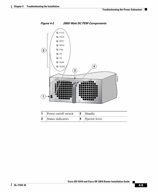
Figure 4-2 identifies the components of a DC PEM.
4-8Cisco XR 12410 and Cisco XR 12810 Router Installation Guide
OL-17441-01
Chapter 4 Troubleshooting the InstallationTroubleshooting the Power Subsystem
Figure 4-2 2800 Watt DC PEM Components
1 Power on/off switch 3 Handle
2 Status indicators 4 Ejector lever
INOK
F1LO
F2LO
RPF1
RPF2
FAIL
OC
OT
DCOK
1292
75
1
34
INOK
F1LO
F2LO
RPF1
RPF2
FAIL
OC
OT
DCOK
2
4-9Cisco XR 12410 and Cisco XR 12810 Router Installation Guide
OL-17441-01
Chapter 4 Troubleshooting the InstallationTroubleshooting the Power Subsystem
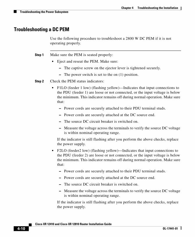
Troubleshooting a DC PEM
Use the following procedure to troubleshoot a 2800 W DC PEM if it is not operating properly.
Step 1 Make sure the PEM is seated properly:
• Eject and reseat the PEM. Make sure:
– The captive screw on the ejector lever is tightened securely.
– The power switch is set to the on (1) position.
Step 2 Check the PEM status indicators:
• F1LO (feeder 1 low) (flashing yellow)—Indicates that input connections to the PDU (feeder 1) are loose or not connected, or the input voltage is below the minimum. This indicator remains off during normal operation. Make sure that:
– Power cords are securely attached to their PDU terminal studs.
– Power cords are securely attached at the DC source end.
– The source DC circuit breaker is switched on.
– Measure the voltage across the terminals to verify the source DC voltage is within nominal operating range.
If the indicator is still flashing after you perform the above checks, replace the power supply.
• F2LO (feeder2 low) (flashing yellow)—Indicates that input connections to the PDU (feeder 2) are loose or not connected, or the input voltage is below the minimum. This indicator remains off during normal operation. Make sure that:
– Power cords are securely attached to their PDU terminal studs.
– Power cords are securely attached at the DC source end.
– The source DC circuit breaker is switched on.
– Measure the voltage across the terminals to verify the source DC voltage is within nominal operating range.
If the indicator is still flashing after you perform the above checks, replace the power supply.
4-10Cisco XR 12410 and Cisco XR 12810 Router Installation Guide
OL-17441-01
Chapter 4 Troubleshooting the InstallationTroubleshooting the Power Subsystem
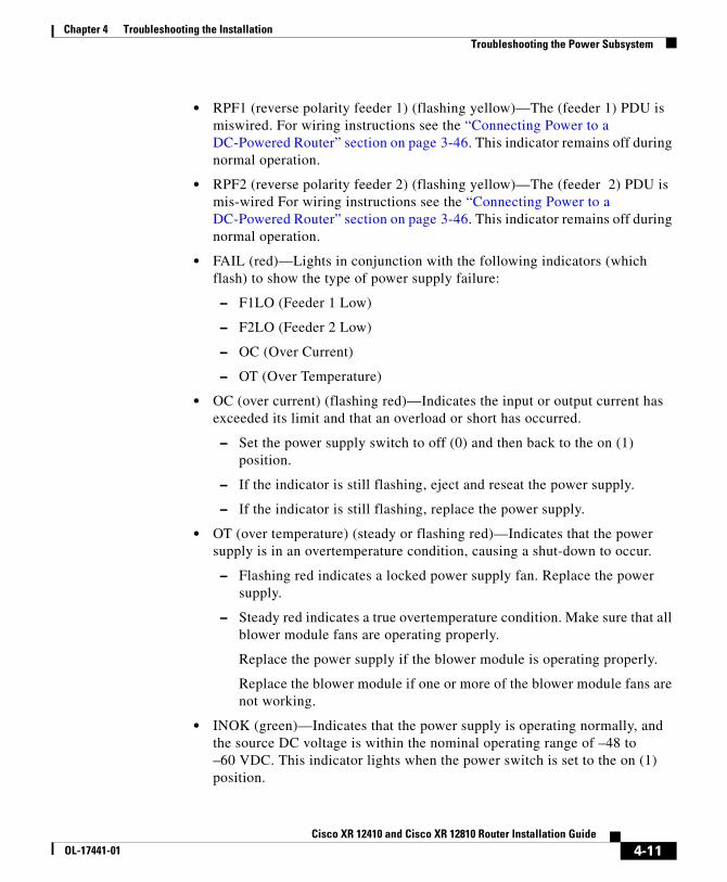
• RPF1 (reverse polarity feeder 1) (flashing yellow)—The (feeder 1) PDU is miswired. For wiring instructions see the “Connecting Power to a DC-Powered Router” section on page 3-46. This indicator remains off during normal operation.
• RPF2 (reverse polarity feeder 2) (flashing yellow)—The (feeder 2) PDU is mis-wired For wiring instructions see the “Connecting Power to a DC-Powered Router” section on page 3-46. This indicator remains off during normal operation.
• FAIL (red)—Lights in conjunction with the following indicators (which flash) to show the type of power supply failure:
– F1LO (Feeder 1 Low)
– F2LO (Feeder 2 Low)
– OC (Over Current)
– OT (Over Temperature)
• OC (over current) (flashing red)—Indicates the input or output current has exceeded its limit and that an overload or short has occurred.
– Set the power supply switch to off (0) and then back to the on (1) position.
– If the indicator is still flashing, eject and reseat the power supply.
– If the indicator is still flashing, replace the power supply.
• OT (over temperature) (steady or flashing red)—Indicates that the power supply is in an overtemperature condition, causing a shut-down to occur.
– Flashing red indicates a locked power supply fan. Replace the power supply.
– Steady red indicates a true overtemperature condition. Make sure that all blower module fans are operating properly.
Replace the power supply if the blower module is operating properly.
Replace the blower module if one or more of the blower module fans are not working.
• INOK (green)—Indicates that the power supply is operating normally, and the source DC voltage is within the nominal operating range of –48 to –60 VDC. This indicator lights when the power switch is set to the on (1) position.
4-11Cisco XR 12410 and Cisco XR 12810 Router Installation Guide
OL-17441-01
Chapter 4 Troubleshooting the InstallationTroubleshooting the Power Subsystem
– If the INOK indicator is off, replace the power supply.
• DCOK (green)—Indicates that the power supply is operating normally, and is within the nominal operating range. This indicator lights a few seconds after the INOK indicator lights.
– If the DCOK indicator is off, replace the power supply.
Because there are redundant power supplies, a problem with the DC output voltage to the backplane from only one PEM should not affect router operation. When the router is equipped with two DC power supplies, it powers on and operates even if one power supply fails.
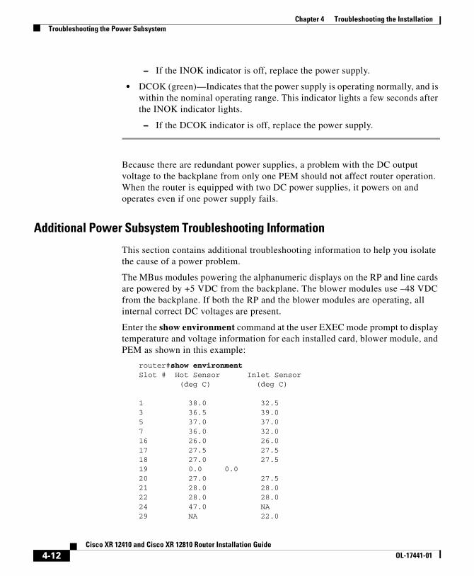
Additional Power Subsystem Troubleshooting Information
This section contains additional troubleshooting information to help you isolate the cause of a power problem.
The MBus modules powering the alphanumeric displays on the RP and line cards are powered by +5 VDC from the backplane. The blower modules use –48 VDC from the backplane. If both the RP and the blower modules are operating, all internal correct DC voltages are present.
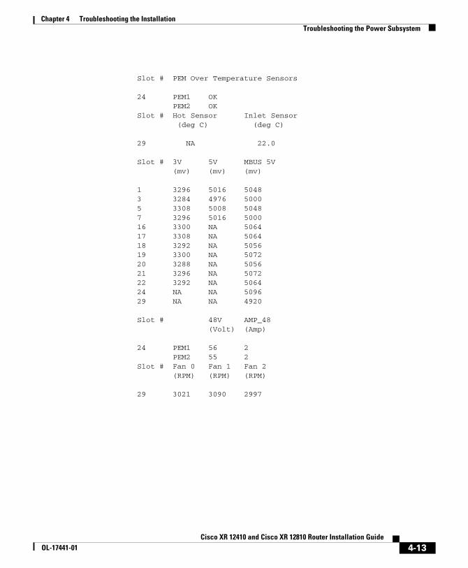
Enter the show environment command at the user EXEC mode prompt to display temperature and voltage information for each installed card, blower module, and PEM as shown in this example:
router#show environmentSlot # Hot Sensor Inlet Sensor (deg C) (deg C)
1 38.0 32.53 36.5 39.05 37.0 37.07 36.0 32.016 26.0 26.017 27.5 27.518 27.0 27.519 0.0 0.020 27.0 27.521 28.0 28.022 28.0 28.024 47.0 NA29 NA 22.0
4-12Cisco XR 12410 and Cisco XR 12810 Router Installation Guide
OL-17441-01
Chapter 4 Troubleshooting the InstallationTroubleshooting the Power Subsystem
Slot # PEM Over Temperature Sensors
24 PEM1 OK PEM2 OKSlot # Hot Sensor Inlet Sensor (deg C) (deg C) 29 NA 22.0
Slot # 3V 5V MBUS 5V (mv) (mv) (mv)
1 3296 5016 50483 3284 4976 50005 3308 5008 50487 3296 5016 500016 3300 NA 506417 3308 NA 506418 3292 NA 505619 3300 NA 507220 3288 NA 505621 3296 NA 507222 3292 NA 506424 NA NA 509629 NA NA 4920
Slot # 48V AMP_48 (Volt) (Amp)
24 PEM1 56 2 PEM2 55 2Slot # Fan 0 Fan 1 Fan 2 (RPM) (RPM) (RPM)
29 3021 3090 2997
4-13Cisco XR 12410 and Cisco XR 12810 Router Installation Guide
OL-17441-01
Chapter 4 Troubleshooting the InstallationTroubleshooting the Power Subsystem
Troubleshooting the Power Distribution SystemThe power distribution system consists of:
• AC or DC PEMs which supply –48 VDC to the backplane,
• The chassis backplane which carries voltage to chassis components.
• DC-to-DC converters which convert –48 VDC from the backplane to the correct voltages required by the line cards.
Use the following procedure to troubleshoot the power distribution system.
Step 1 Check each power supply to make sure that:
• The ejector lever is fully closed and properly secured by the its captive screw.
• The Pwr OK indicator is on.
• The Fault and Temp indicators are both off.
If the power supplies meet the above criteria, then the correct source power is present and within tolerance. The power supplies are functioning properly.
Step 2 Make sure the blower module is operating.
• If the blower module is functioning, then the –48 VDC from the chassis backplane and the cables from the backplane to the blower module are functioning properly.
• If the blower module is not functioning, there may be a problem with either the blower module itself, or the –48 VDC power supplied to the blower module. Eject and reseat the blower module.
• If the blower module is still not operating there could be a problem with the blower module controller card or cable. Replace the blower module.
• Contact your Cisco representative if replacing the blower module does not fix the problem.
4-14Cisco XR 12410 and Cisco XR 12810 Router Installation Guide
OL-17441-01
Chapter 4 Troubleshooting the InstallationTroubleshooting the Processor Subsystem
Troubleshooting the Processor SubsystemThe router processor subsystem consists of the route processor, line cards, and alarm cards. The RP and the line cards have two onboard processors; one serves as the main (or master) processor, and the other serves as the MBus module processor. The MBus module processor monitors the environment and controls the onboard DC-to-DC converters.
Note A minimally configured router must have an RP installed in slot 9 of the card cage to operate. If the router is equipped with a redundant RP, the redundant RP must be installed in slot 8 of the card cage.
This section contains information to troubleshoot the processor subsystem, including:
• Performance Route Processor Overview, page 4-16
• Troubleshooting the Route Processor, page 4-21
• PRP-3 Alphanumeric LEDs, page 4-24
• Troubleshooting Using the Alarm Display, page 4-35
4-15Cisco XR 12410 and Cisco XR 12810 Router Installation Guide
OL-17441-01
Chapter 4 Troubleshooting the InstallationTroubleshooting the Processor Subsystem
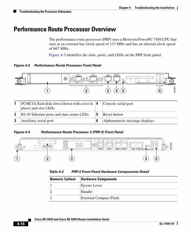
Performance Route Processor OverviewThe performance route processor (PRP) uses a Motorola PowerPC 7450 CPU that runs at an external bus clock speed of 133 MHz and has an internal clock speed of 667 MHz.
Figure 4-3 identifies the slots, ports, and LEDs on the PRP front panel.
Figure 4-3 Performance Route Processor Front Panel
Figure 4-4 Performance Route Processor 3 (PRP-3) Front Panel
Table 4-2 PRP-3 Front Panel Hardware Components Detail
1 PCMCIA flash disk slots (shown with cover in place) and slot LEDs
4 Console serial port
2 RJ-45 Ethernet ports and data status LEDs 5 Reset button
3 Auxiliary serial port 6 Alphanumeric message displays
EJECT
RX
TX
PRIMARY
SLOT-1
SLOT-0
LINK
EN
RX
TX
ETH 1ETH 0 AUX CONSOLE
PERFORMANCE ROUTE PROCESSOR 1 (PRP-1)LINK
PRIMARY
ENRESET
1293
07
1 3 4 52 6
2723
59
CONSOLEAUXBITS 1BITS 0ETH 1ETH 0 PERFORMANCE RP 3
RESET
ACTSIG ACT
SIGDATALIN
KDATA
LINK
1 3 4 52
Numeric Callout Hardware Components
1 Ejecter Lever
2 Handle
3 External Compact Flash
4-16Cisco XR 12410 and Cisco XR 12810 Router Installation Guide
OL-17441-01
Chapter 4 Troubleshooting the InstallationTroubleshooting the Processor Subsystem
PRP-3 is the route processor for the Cisco XR 12404 and 12804 Router chassis running Cisco IOS XR Software Release 3.8.0 or a later release. The PRP-3 is available as product number PRP-3 or PRP-3= for a primary route processor and is available as PRP-3/R for a redundant route processor. PRP-3 has significant improvements over PRP-2. These improvements include increased speed, improved scalability, higher system memory, faster packet processing. Because PRP-3 does not support Cisco IOS, the bootflash memory no longer exists in PRP-3. PRP-3 ROMMON has software intelligence to download a Cisco IOS XR image without the support of bootflash memory.
Note PRP-3 supports Cisco XR 12410 (10 G per slot fabric) and Cisco XR 12810 (40 G per slot fabric) Router chassis only. PRP-3 does not support Cisco XR 12004, 12006, 12010, and 12016 Router chassis (2.5 G low-speed fabric).
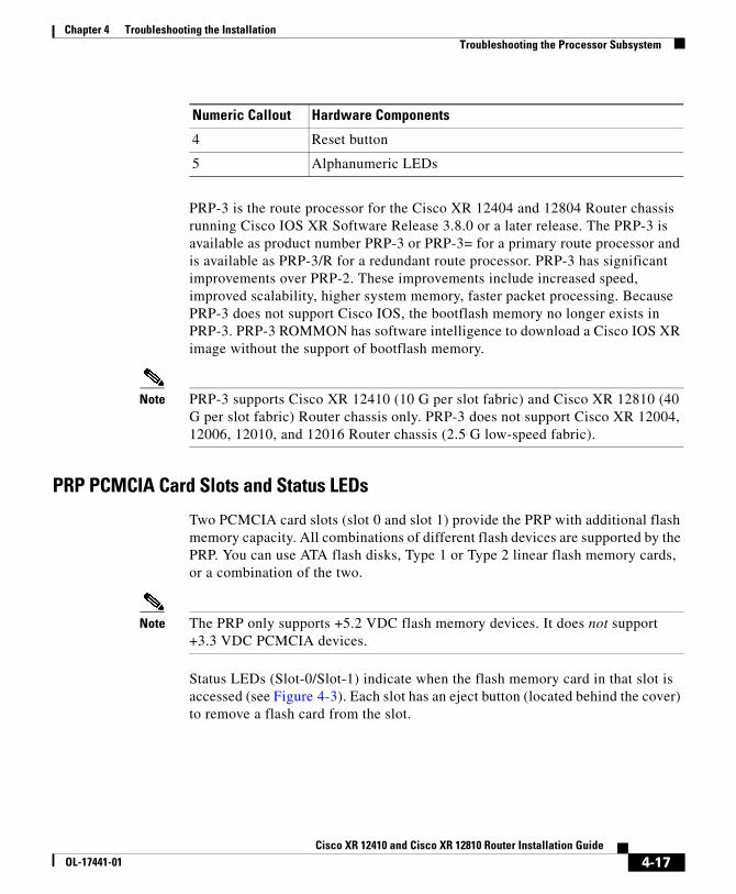
PRP PCMCIA Card Slots and Status LEDs
Two PCMCIA card slots (slot 0 and slot 1) provide the PRP with additional flash memory capacity. All combinations of different flash devices are supported by the PRP. You can use ATA flash disks, Type 1 or Type 2 linear flash memory cards, or a combination of the two.
Note The PRP only supports +5.2 VDC flash memory devices. It does not support +3.3 VDC PCMCIA devices.
Status LEDs (Slot-0/Slot-1) indicate when the flash memory card in that slot is accessed (see Figure 4-3). Each slot has an eject button (located behind the cover) to remove a flash card from the slot.
4 Reset button
5 Alphanumeric LEDs
Numeric Callout Hardware Components
4-17Cisco XR 12410 and Cisco XR 12810 Router Installation Guide
OL-17441-01
Chapter 4 Troubleshooting the InstallationTroubleshooting the Processor Subsystem
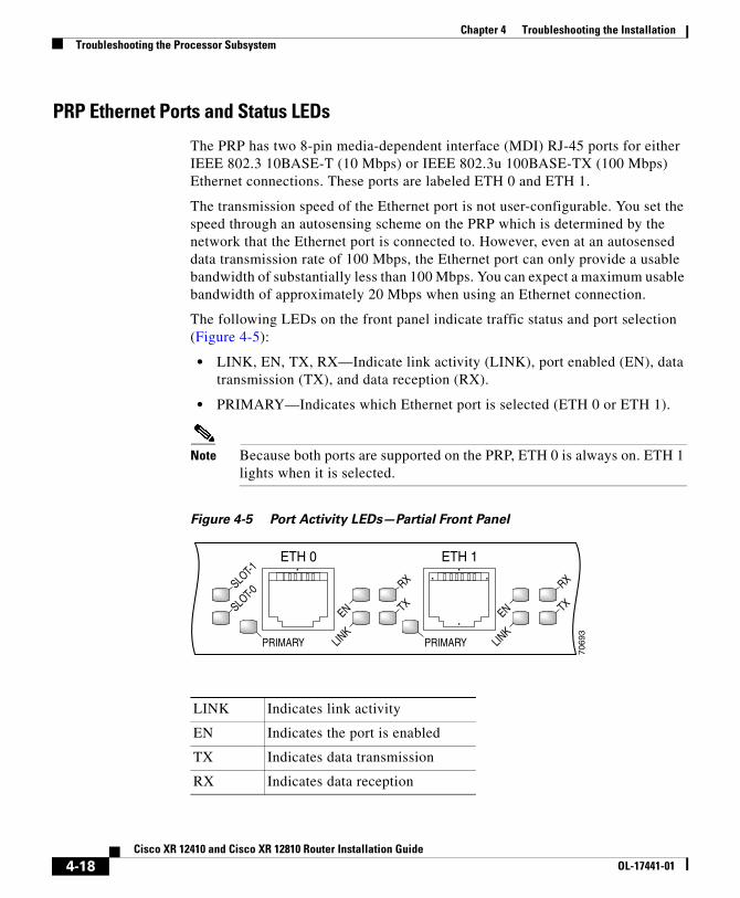
PRP Ethernet Ports and Status LEDs
The PRP has two 8-pin media-dependent interface (MDI) RJ-45 ports for either IEEE 802.3 10BASE-T (10 Mbps) or IEEE 802.3u 100BASE-TX (100 Mbps) Ethernet connections. These ports are labeled ETH 0 and ETH 1.
The transmission speed of the Ethernet port is not user-configurable. You set the speed through an autosensing scheme on the PRP which is determined by the network that the Ethernet port is connected to. However, even at an autosensed data transmission rate of 100 Mbps, the Ethernet port can only provide a usable bandwidth of substantially less than 100 Mbps. You can expect a maximum usable bandwidth of approximately 20 Mbps when using an Ethernet connection.
The following LEDs on the front panel indicate traffic status and port selection (Figure 4-5):
• LINK, EN, TX, RX—Indicate link activity (LINK), port enabled (EN), data transmission (TX), and data reception (RX).
• PRIMARY—Indicates which Ethernet port is selected (ETH 0 or ETH 1).
Note Because both ports are supported on the PRP, ETH 0 is always on. ETH 1 lights when it is selected.
Figure 4-5 Port Activity LEDs—Partial Front Panel
LINK Indicates link activity
EN Indicates the port is enabled
TX Indicates data transmission
RX Indicates data reception
RX
TX
PRIMARY
SLOT-1
SLOT-0
LINK
EN
RX
TX
ETH 1ETH 0
LINK
PRIMARY
EN
7069
3
4-18Cisco XR 12410 and Cisco XR 12810 Router Installation Guide
OL-17441-01
Chapter 4 Troubleshooting the InstallationTroubleshooting the Processor Subsystem
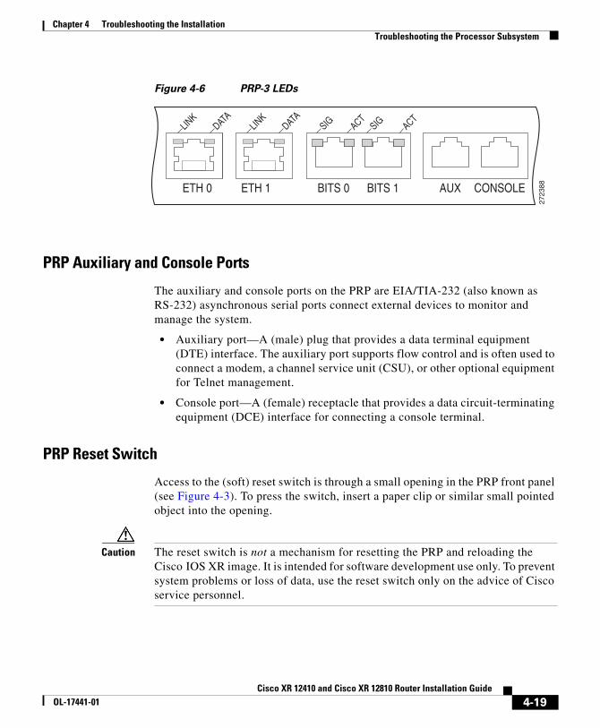
Figure 4-6 PRP-3 LEDs
PRP Auxiliary and Console Ports
The auxiliary and console ports on the PRP are EIA/TIA-232 (also known as RS-232) asynchronous serial ports connect external devices to monitor and manage the system.
• Auxiliary port—A (male) plug that provides a data terminal equipment (DTE) interface. The auxiliary port supports flow control and is often used to connect a modem, a channel service unit (CSU), or other optional equipment for Telnet management.
• Console port—A (female) receptacle that provides a data circuit-terminating equipment (DCE) interface for connecting a console terminal.
PRP Reset Switch
Access to the (soft) reset switch is through a small opening in the PRP front panel (see Figure 4-3). To press the switch, insert a paper clip or similar small pointed object into the opening.
Caution The reset switch is not a mechanism for resetting the PRP and reloading the Cisco IOS XR image. It is intended for software development use only. To prevent system problems or loss of data, use the reset switch only on the advice of Cisco service personnel.
ACTSIGACT
SIG
BITS 0
DATALIN
KDATA
LINK
ETH 1ETH 0
2723
88BITS 1 AUX CONSOLE
4-19Cisco XR 12410 and Cisco XR 12810 Router Installation Guide
OL-17441-01
Chapter 4 Troubleshooting the InstallationTroubleshooting the Processor Subsystem
Pressing the reset switch causes a non-maskable interrupt (NMI) and places the PRP in ROM monitor mode. When the PRP enters ROM monitor mode, its behavior depends on the setting of the PRP software configuration register. For example, if the boot field of the software configuration register is set to:
• 0x0—The PRP remains at the ROM monitor prompt (rommon>) and waits for a user command to boot the system manually.
• 0x1—The system automatically boots the first Cisco IOS XR image found in flash memory on the PRP.
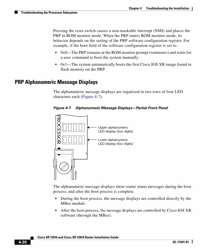
PRP Alphanumeric Message Displays
The alphanumeric message displays are organized in two rows of four LED characters each (Figure 4-7).
Figure 4-7 Alphanumeric Message Displays—Partial Front Panel
The alphanumeric message displays show router status messages during the boot process, and after the boot process is complete.
• During the boot process, the message displays are controlled directly by the MBus module.
• After the boot process, the message displays are controlled by Cisco IOS XR software (through the MBus).
H10
780
PRO
CE
SSOR
Upper alphanumericLED display (four digits)
Lower alphanumericLED display (four digits)
4-20Cisco XR 12410 and Cisco XR 12810 Router Installation Guide
OL-17441-01
Chapter 4 Troubleshooting the InstallationTroubleshooting the Processor Subsystem
The alphanumeric message displays also provide information about different levels of system operation, including the status of the PRP, router error messages, and user-defined status and error messages
Note A list of all system and error messages appears in the Cisco IOS XR System Error Messages publication.
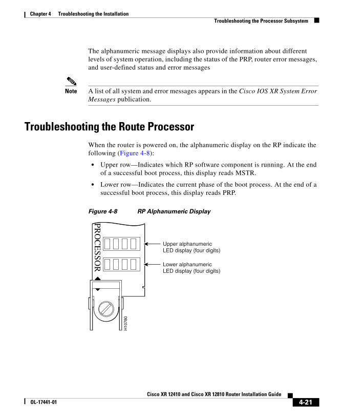
Troubleshooting the Route ProcessorWhen the router is powered on, the alphanumeric display on the RP indicate the following (Figure 4-8):
• Upper row—Indicates which RP software component is running. At the end of a successful boot process, this display reads MSTR.
• Lower row—Indicates the current phase of the boot process. At the end of a successful boot process, this display reads PRP.
Figure 4-8 RP Alphanumeric Display
H10
780
PRO
CE
SSOR
Upper alphanumericLED display (four digits)
Lower alphanumericLED display (four digits)
4-21Cisco XR 12410 and Cisco XR 12810 Router Installation Guide
OL-17441-01
Chapter 4 Troubleshooting the InstallationTroubleshooting the Processor Subsystem
Troubleshooting Using the RP Alphanumeric Display
You can use the alphanumeric display to isolate a problem with the RP. The two rows on the alphanumeric display are powered separately:
• The upper row receives power from the DC-to-DC converters on the RP.
• The lower row is powered directly from the MBus on the RP through the chassis backplane.
– If the lower row is not operating, the MBus module may be malfunctioning.
– If the MBus module is operating, the lower row could be on even if the RP failed to powered on.
• If neither the upper nor the lower row is on, but the power modules and the blower modules are operational, the RP may not be installed properly, or the +5 VDC output from the chassis backplane is faulty.
– Make sure that the system is powered on.
– Initialize the RP by ejecting it from the chassis backplane and then reseating it.
Caution The soft reset (NMI) switch is not a mechanism for resetting the RP and reloading the Cisco software image. It is intended for software development use. To prevent system problems or loss of data, use the soft reset switch only when instructed by a Cisco certified service representative.
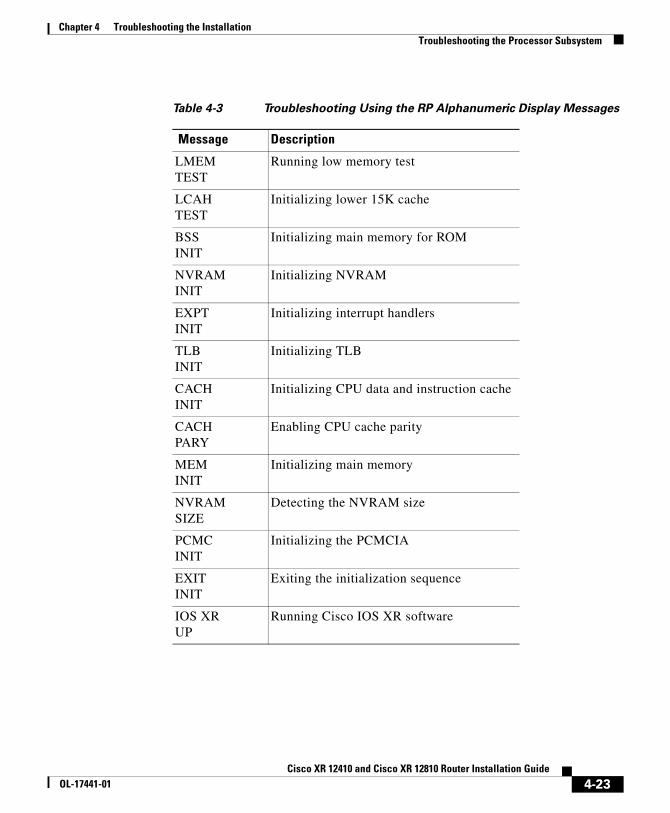
• If both the upper and the lower displays are operating, check the meaning of the messages (see Table 4-3).
When the DC-to-DC converters are powered-on by the MBus module, the RP processor begins the boot process and displays various status messages. Some messages appear briefly; while others appear for several seconds. If the messages appear to stop at a particular point, the boot process may be halted.
– Make a note of the message.
– Turn off power to the router, then turn on the power again to reset the router and start the boot process. If the router halts again, replace the RP (see “Removing and Replacing Cards from the Line Card and RP Card Cage” section on page 5-38).
4-22Cisco XR 12410 and Cisco XR 12810 Router Installation Guide
OL-17441-01
Chapter 4 Troubleshooting the InstallationTroubleshooting the Processor Subsystem
Table 4-3 Troubleshooting Using the RP Alphanumeric Display Messages
Message Description
LMEMTEST
Running low memory test
LCAHTEST
Initializing lower 15K cache
BSSINIT
Initializing main memory for ROM
NVRAMINIT
Initializing NVRAM
EXPTINIT
Initializing interrupt handlers
TLBINIT
Initializing TLB
CACHINIT
Initializing CPU data and instruction cache
CACHPARY
Enabling CPU cache parity
MEMINIT
Initializing main memory
NVRAMSIZE
Detecting the NVRAM size
PCMCINIT
Initializing the PCMCIA
EXITINIT
Exiting the initialization sequence
IOS XRUP
Running Cisco IOS XR software
4-23Cisco XR 12410 and Cisco XR 12810 Router Installation Guide
OL-17441-01
Chapter 4 Troubleshooting the InstallationTroubleshooting the Processor Subsystem
PRP-3 Alphanumeric LEDs
The following section discusses the alphanumeric LED messages and the console output displayed in sequence for a single PRP-3 and for dual PRP-3. The alphanumeric LED messages help in identifying the state of the route processor and accordingly troubleshooting the problems faced.
Single PRP-3 Scenario
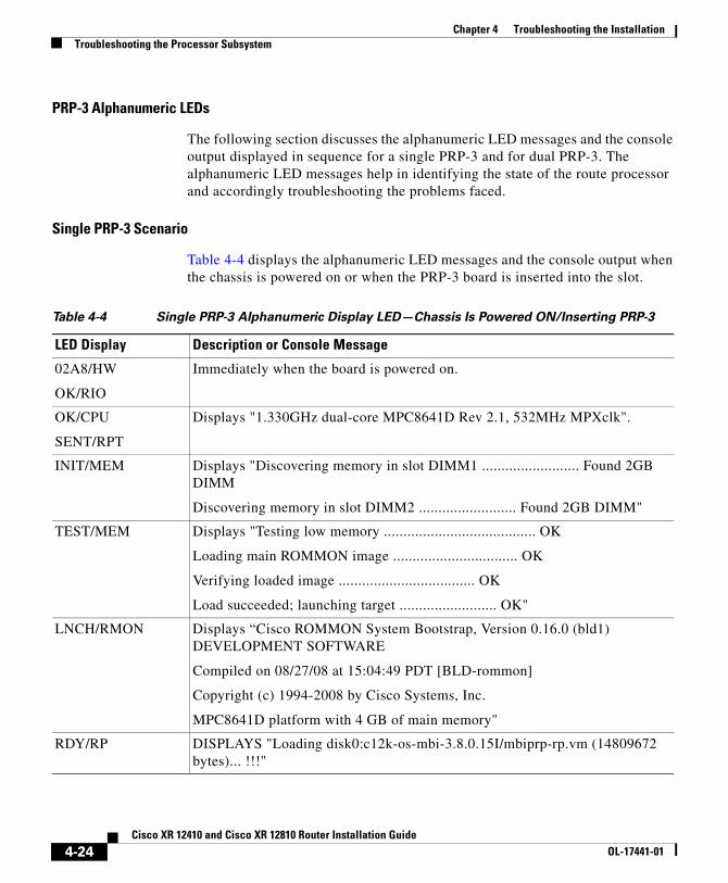
Table 4-4 displays the alphanumeric LED messages and the console output when the chassis is powered on or when the PRP-3 board is inserted into the slot.
Table 4-4 Single PRP-3 Alphanumeric Display LED—Chassis Is Powered ON/Inserting PRP-3
LED Display Description or Console Message
02A8/HW
OK/RIO
Immediately when the board is powered on.
OK/CPU
SENT/RPT
Displays "1.330GHz dual-core MPC8641D Rev 2.1, 532MHz MPXclk".
INIT/MEM Displays "Discovering memory in slot DIMM1 ......................... Found 2GB DIMM
Discovering memory in slot DIMM2 ......................... Found 2GB DIMM"
TEST/MEM Displays "Testing low memory ....................................... OK
Loading main ROMMON image ................................ OK
Verifying loaded image ................................... OK
Load succeeded; launching target ......................... OK"
LNCH/RMON Displays “Cisco ROMMON System Bootstrap, Version 0.16.0 (bld1) DEVELOPMENT SOFTWARE
Compiled on 08/27/08 at 15:04:49 PDT [BLD-rommon]
Copyright (c) 1994-2008 by Cisco Systems, Inc.
MPC8641D platform with 4 GB of main memory"
RDY/RP DISPLAYS "Loading disk0:c12k-os-mbi-3.8.0.15I/mbiprp-rp.vm (14809672 bytes)... !!!"
4-24Cisco XR 12410 and Cisco XR 12810 Router Installation Guide
OL-17441-01
Chapter 4 Troubleshooting the InstallationTroubleshooting the Processor Subsystem
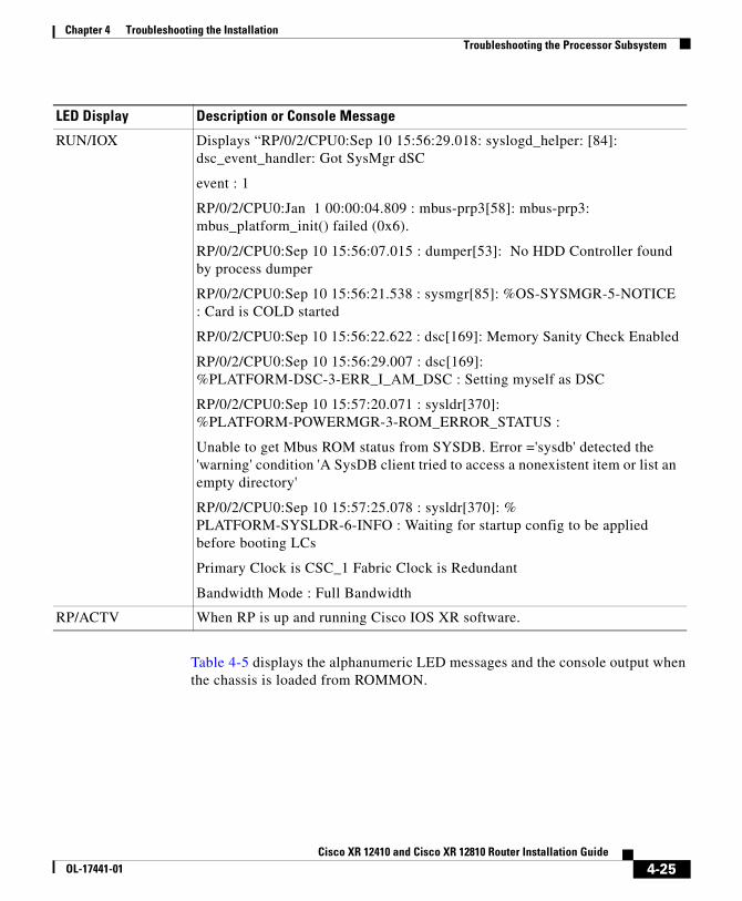
Table 4-5 displays the alphanumeric LED messages and the console output when the chassis is loaded from ROMMON.
RUN/IOX Displays “RP/0/2/CPU0:Sep 10 15:56:29.018: syslogd_helper: [84]: dsc_event_handler: Got SysMgr dSC
event : 1
RP/0/2/CPU0:Jan 1 00:00:04.809 : mbus-prp3[58]: mbus-prp3: mbus_platform_init() failed (0x6).
RP/0/2/CPU0:Sep 10 15:56:07.015 : dumper[53]: No HDD Controller found by process dumper
RP/0/2/CPU0:Sep 10 15:56:21.538 : sysmgr[85]: %OS-SYSMGR-5-NOTICE : Card is COLD started
RP/0/2/CPU0:Sep 10 15:56:22.622 : dsc[169]: Memory Sanity Check Enabled
RP/0/2/CPU0:Sep 10 15:56:29.007 : dsc[169]: %PLATFORM-DSC-3-ERR_I_AM_DSC : Setting myself as DSC
RP/0/2/CPU0:Sep 10 15:57:20.071 : sysldr[370]: %PLATFORM-POWERMGR-3-ROM_ERROR_STATUS :
Unable to get Mbus ROM status from SYSDB. Error ='sysdb' detected the 'warning' condition 'A SysDB client tried to access a nonexistent item or list an empty directory'
RP/0/2/CPU0:Sep 10 15:57:25.078 : sysldr[370]: % PLATFORM-SYSLDR-6-INFO : Waiting for startup config to be applied before booting LCs
Primary Clock is CSC_1 Fabric Clock is Redundant
Bandwidth Mode : Full Bandwidth
RP/ACTV When RP is up and running Cisco IOS XR software.
LED Display Description or Console Message
4-25Cisco XR 12410 and Cisco XR 12810 Router Installation Guide
OL-17441-01
Chapter 4 Troubleshooting the InstallationTroubleshooting the Processor Subsystem
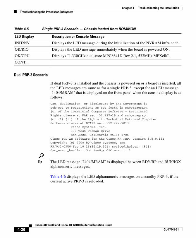
Table 4-5 Single PRP-3 Scenario — Chassis loaded from ROMMON
Dual PRP-3 Scenario
If dual PRP-3 is installed and the chassis is powered on or a board is inserted, all the LED messages are same as for a single PRP-3, except for an LED message ‘1404/MRAM’ that is displayed on the front panel when the console display is as follows:
Use, duplication, or disclosure by the Government issubject to restrictions as set forth in subparagraph(c) of the Commercial Computer Software - RestrictedRights clause at FAR sec. 52.227-19 and subparagraph(c) (1) (ii) of the Rights in Technical Data and ComputerSoftware clause at DFARS sec. 252.227-7013. cisco Systems, Inc. 170 West Tasman Drive San Jose, California 95134-1706Cisco IOS XR Software for the Cisco XR PRP, Version 3.8.0.15ICopyright (c) 2008 by Cisco Systems, Inc.RP/0/2/CPU0:Sep 10 16:34:19.351: syslogd_helper: [84]: dsc_event_handler: Got SysMgr dSC event : 1
Tip The LED message “I404/MRAM” is displayed between RDY/RP and RUN/IOX alphanumeric messages.
Table 4-6 displays the LED alphanumeric messages on a standby PRP-3, if the current active PRP-3 is reloaded.
LED Display Description or Console Message
INIT/NV Displays the LED message during the initialization of the NVRAM infra code.
OK/RIO Displays the LED message immediately when the board is powered ON.
OK/CPU Displays "1.330GHz dual-core MPC8641D Rev 2.1, 532MHz MPXclk".
CONT...
4-26Cisco XR 12410 and Cisco XR 12810 Router Installation Guide
OL-17441-01
Chapter 4 Troubleshooting the InstallationTroubleshooting the Processor Subsystem
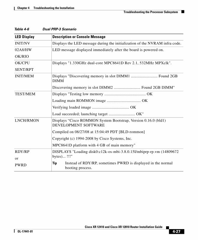
Table 4-6 Dual PRP-3 Scenario
LED Display Description or Console Message
INIT/NV Displays the LED message during the initialization of the NVRAM infra code.
02A8/HW
OK/RIO
LED message displayed immediately after the board is powered on.
OK/CPU
SENT/RPT
Displays "1.330GHz dual-core MPC8641D Rev 2.1, 532MHz MPXclk".
INIT/MEM Displays "Discovering memory in slot DIMM1 ......................... Found 2GB DIMM
Discovering memory in slot DIMM2 ......................... Found 2GB DIMM"
TEST/MEM Displays "Testing low memory ....................................... OK
Loading main ROMMON image ................................ OK
Verifying loaded image ................................... OK
Load succeeded; launching target ......................... OK"
LNCH/RMON Displays “Cisco ROMMON System Bootstrap, Version 0.16.0 (bld1) DEVELOPMENT SOFTWARE
Compiled on 08/27/08 at 15:04:49 PDT [BLD-rommon]
Copyright (c) 1994-2008 by Cisco Systems, Inc.
MPC8641D platform with 4 GB of main memory"
RDY/RP
or
PWRD
DISPLAYS "Loading disk0:c12k-os-mbi-3.8.0.15I/mbiprp-rp.vm (14809672 bytes)... !!!"
Tip Instead of RDY/RP, sometimes PWRD is displayed in the normal booting process.
4-27Cisco XR 12410 and Cisco XR 12810 Router Installation Guide
OL-17441-01
Chapter 4 Troubleshooting the InstallationTroubleshooting the Processor Subsystem
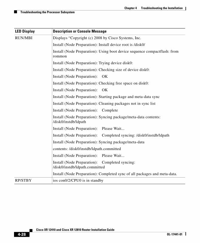
RUN/MBI Displays “Copyright (c) 2008 by Cisco Systems, Inc.
Install (Node Preparation): Install device root is /disk0/
Install (Node Preparation): Using boot device sequence compactflash: from rommon
Install (Node Preparation): Trying device disk0:
Install (Node Preparation): Checking size of device disk0:
Install (Node Preparation): OK
Install (Node Preparation): Checking free space on disk0:
Install (Node Preparation): OK
Install (Node Preparation): Starting package and meta-data sync
Install (Node Preparation): Cleaning packages not in sync list
Install (Node Preparation): Complete
Install (Node Preparation): Syncing package/meta-data contents: /disk0/instdb/ldpath
Install (Node Preparation): Please Wait...
Install (Node Preparation): Completed syncing: /disk0/instdb/ldpath
Install (Node Preparation): Syncing package/meta-data
contents: /disk0/instdb/ldpath.committed
Install (Node Preparation): Please Wait...
Install (Node Preparation): Completed syncing: /disk0/instdb/ldpath.committed
Install (Node Preparation): Completed sync of all packages and meta-data.
RP/STBY ios con0/2/CPU0 is in standby
LED Display Description or Console Message
4-28Cisco XR 12410 and Cisco XR 12810 Router Installation Guide
OL-17441-01
Chapter 4 Troubleshooting the InstallationTroubleshooting the Processor Subsystem
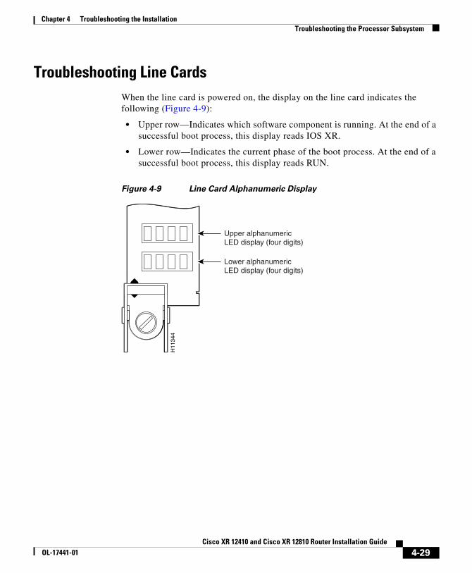
Troubleshooting Line CardsWhen the line card is powered on, the display on the line card indicates the following (Figure 4-9):
• Upper row—Indicates which software component is running. At the end of a successful boot process, this display reads IOS XR.
• Lower row—Indicates the current phase of the boot process. At the end of a successful boot process, this display reads RUN.
Figure 4-9 Line Card Alphanumeric Display
H11
344
Upper alphanumericLED display (four digits)
Lower alphanumericLED display (four digits)
4-29Cisco XR 12410 and Cisco XR 12810 Router Installation Guide
OL-17441-01
Chapter 4 Troubleshooting the InstallationTroubleshooting the Processor Subsystem
Troubleshooting Using the Line Card Alphanumeric Display
You can analyze the alphanumeric displays to isolate a problem with the line card. The two rows of the alphanumeric display are powered separately:
• The upper row receives power from the DC-to-DC converters on the line card.
• The lower row is powered directly from the MBus on the line card through the chassis backplane.
– If the lower row is not operating the MBus module may be malfunctioning.
– If the MBus module is operating, the lower row could be on even if the RP failed to powered on.
• If neither the upper or lower row is on, but the power modules and the blower modules are operational, the line card may not be installed properly, or the +5 VDC output from the chassis backplane is faulty.
– Make sure that the system is powered on.
– Initialize the line card by ejecting it from the chassis backplane and then reseating it.
• If both the upper and lower rows are operating, check the status messages (see Table 4-7).
When the DC-to-DC converters are powered-on by the MBus module, the line card processor begins the boot process and displays various status messages. Some messages appear briefly; while others appear for several seconds.
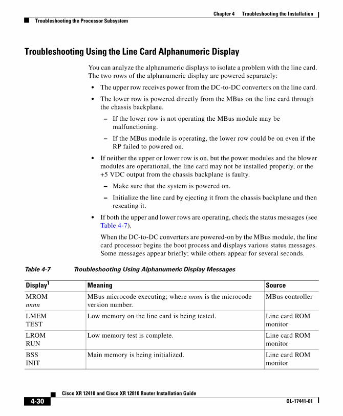
Table 4-7 Troubleshooting Using Alphanumeric Display Messages
Display1 Meaning Source
MROMnnnn
MBus microcode executing; where nnnn is the microcode version number.
MBus controller
LMEMTEST
Low memory on the line card is being tested. Line card ROM monitor
LROMRUN
Low memory test is complete. Line card ROM monitor
BSSINIT
Main memory is being initialized. Line card ROM monitor
4-30Cisco XR 12410 and Cisco XR 12810 Router Installation Guide
OL-17441-01
Chapter 4 Troubleshooting the InstallationTroubleshooting the Processor Subsystem
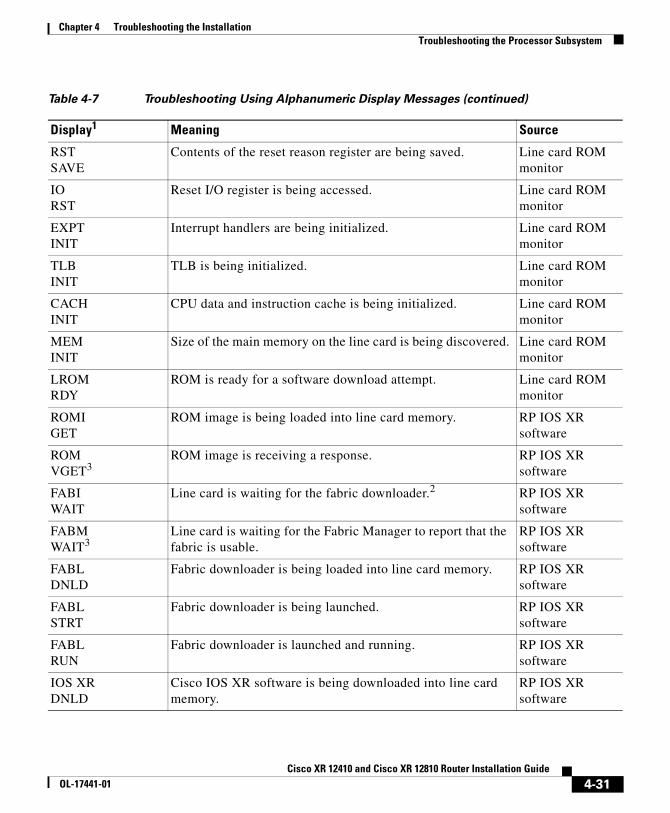
RSTSAVE
Contents of the reset reason register are being saved. Line card ROM monitor
IORST
Reset I/O register is being accessed. Line card ROM monitor
EXPTINIT
Interrupt handlers are being initialized. Line card ROM monitor
TLBINIT
TLB is being initialized. Line card ROM monitor
CACHINIT
CPU data and instruction cache is being initialized. Line card ROM monitor
MEMINIT
Size of the main memory on the line card is being discovered. Line card ROM monitor
LROMRDY
ROM is ready for a software download attempt. Line card ROM monitor
ROMIGET
ROM image is being loaded into line card memory. RP IOS XR software
ROMVGET3
ROM image is receiving a response. RP IOS XR software
FABIWAIT
Line card is waiting for the fabric downloader.2 RP IOS XR software
FABMWAIT3
Line card is waiting for the Fabric Manager to report that the fabric is usable.
RP IOS XR software
FABLDNLD
Fabric downloader is being loaded into line card memory. RP IOS XR software
FABLSTRT
Fabric downloader is being launched. RP IOS XR software
FABLRUN
Fabric downloader is launched and running. RP IOS XR software
IOS XRDNLD
Cisco IOS XR software is being downloaded into line card memory.
RP IOS XR software
Table 4-7 Troubleshooting Using Alphanumeric Display Messages (continued)
Display1 Meaning Source
4-31Cisco XR 12410 and Cisco XR 12810 Router Installation Guide
OL-17441-01
Chapter 4 Troubleshooting the InstallationTroubleshooting the Processor Subsystem
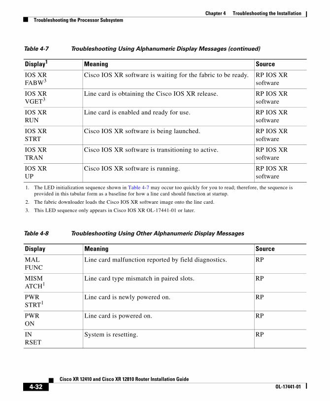
IOS XRFABW3
Cisco IOS XR software is waiting for the fabric to be ready. RP IOS XR software
IOS XRVGET3
Line card is obtaining the Cisco IOS XR release. RP IOS XR software
IOS XRRUN
Line card is enabled and ready for use. RP IOS XR software
IOS XRSTRT
Cisco IOS XR software is being launched. RP IOS XR software
IOS XR TRAN
Cisco IOS XR software is transitioning to active. RP IOS XR software
IOS XRUP
Cisco IOS XR software is running. RP IOS XR software
1. The LED initialization sequence shown in Table 4-7 may occur too quickly for you to read; therefore, the sequence is provided in this tabular form as a baseline for how a line card should function at startup.
2. The fabric downloader loads the Cisco IOS XR software image onto the line card.
3. This LED sequence only appears in Cisco IOS XR OL-17441-01 or later.
Table 4-8 Troubleshooting Using Other Alphanumeric Display Messages
Display Meaning Source
MALFUNC
Line card malfunction reported by field diagnostics. RP
MISMATCH1
Line card type mismatch in paired slots. RP
PWRSTRT1
Line card is newly powered on. RP
PWRON
Line card is powered on. RP
INRSET
System is resetting. RP
Table 4-7 Troubleshooting Using Alphanumeric Display Messages (continued)
Display1 Meaning Source
4-32Cisco XR 12410 and Cisco XR 12810 Router Installation Guide
OL-17441-01
Chapter 4 Troubleshooting the InstallationTroubleshooting the Processor Subsystem
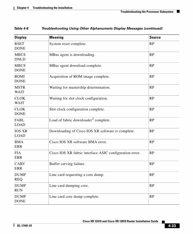
RSETDONE
System reset complete. RP
MBUSDNLD
MBus agent is downloading. RP
MBUSDONE
MBus agent download complete. RP
ROMIDONE
Acquisition of ROM image complete. RP
MSTRWAIT
Waiting for mastership determination. RP
CLOKWAIT
Waiting for slot clock configuration. RP
CLOKDONE
Slot clock configuration complete. RP
FABLLOAD
Load of fabric downloader2 complete. RP
IOS XRLOAD
Downloading of Cisco IOS XR software is complete. RP
BMAERR
Cisco IOS XR software BMA error. RP
FIAERR
Cisco IOS XR fabric interface ASIC configuration error. RP
CARVERR
Buffer carving failure. RP
DUMPREQ
Line card requesting a core dump. RP
DUMPRUN
Line card dumping core. RP
DUMPDONE
Line card core dump complete. RP
Table 4-8 Troubleshooting Using Other Alphanumeric Display Messages (continued)
Display Meaning Source
4-33Cisco XR 12410 and Cisco XR 12810 Router Installation Guide
OL-17441-01
Chapter 4 Troubleshooting the InstallationTroubleshooting the Processor Subsystem
DIAGMODE
Diagnostic mode. RP
DIAGLOAD
Downloading field diagnostics over the MBus. RP
DIAGF_LD
Downloading field diagnostics over the fabric. RP
DIAGSTRT
Launching field diagnostics. RP
DIAGHALT
Cancel field diagnostics. RP
DIAGTEST
Running field diagnostics tests. RP
DIAGPASS1
Field diagnostics completed successfully. RP
POSTSTRT
Launching power-on self-test (POST). RP
UNKNSTAT
Unknown state. RP
ADMNDOWN
Line card is administratively down. RP
SCFGPRES1
Incorrect hw-module slot srp command entered. RP
SCFG1
REDQRequired hw-module slot srp command not entered. RP
1. This LED sequence only appears in Cisco IOS XR OL-17441-01 or later.
2. The fabric downloader loads the Cisco IOS XR software image onto the line card.
Table 4-8 Troubleshooting Using Other Alphanumeric Display Messages (continued)
Display Meaning Source
4-34Cisco XR 12410 and Cisco XR 12810 Router Installation Guide
OL-17441-01
Chapter 4 Troubleshooting the InstallationTroubleshooting the Processor Subsystem
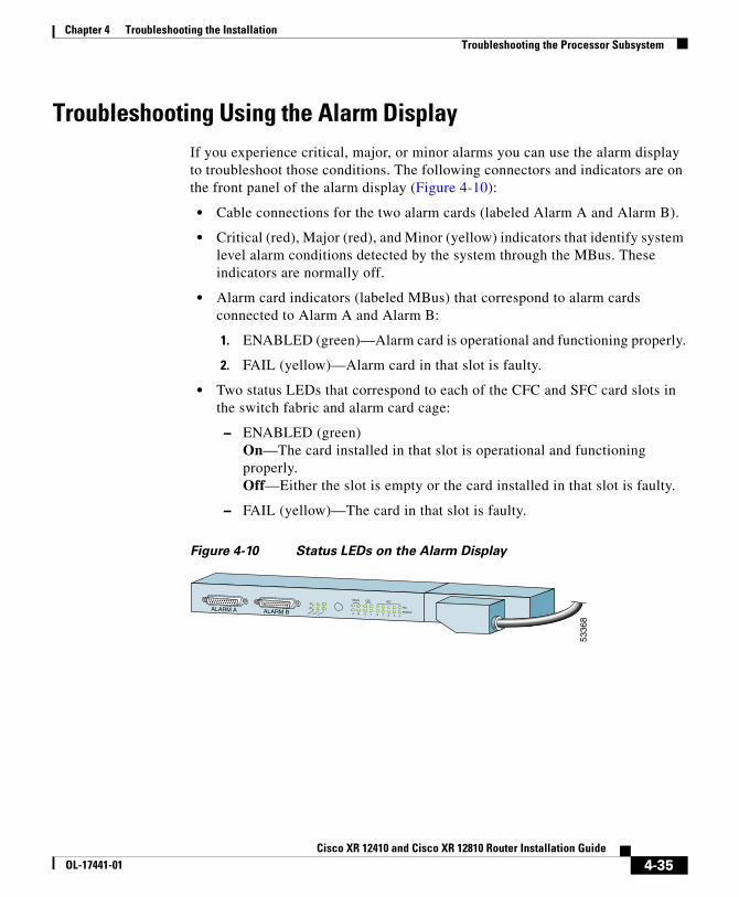
Troubleshooting Using the Alarm DisplayIf you experience critical, major, or minor alarms you can use the alarm display to troubleshoot those conditions. The following connectors and indicators are on the front panel of the alarm display (Figure 4-10):
• Cable connections for the two alarm cards (labeled Alarm A and Alarm B).
• Critical (red), Major (red), and Minor (yellow) indicators that identify system level alarm conditions detected by the system through the MBus. These indicators are normally off.
• Alarm card indicators (labeled MBus) that correspond to alarm cards connected to Alarm A and Alarm B:
1. ENABLED (green)—Alarm card is operational and functioning properly.
2. FAIL (yellow)—Alarm card in that slot is faulty.
• Two status LEDs that correspond to each of the CFC and SFC card slots in the switch fabric and alarm card cage:
– ENABLED (green) On—The card installed in that slot is operational and functioning properly.Off—Either the slot is empty or the card installed in that slot is faulty.
– FAIL (yellow)—The card in that slot is faulty.
Figure 4-10 Status LEDs on the Alarm Display
ALARM A ALARM B
A
A
MBUS
MINOR
B FAIL
ENABLEMAJOR
CRITICALB 0
CSC
1 0
SFC
1 2 3 4
5336
8
4-35Cisco XR 12410 and Cisco XR 12810 Router Installation Guide
OL-17441-01
Chapter 4 Troubleshooting the InstallationTroubleshooting the Processor Subsystem
Monitoring Critical, Major, and Minor Alarm Status
The alarms can warn of an overtemperature condition:
• On a component in the card cage
• A fan failure in a blower module
• An overcurrent condition in a power supply
• An out-of-tolerance voltage on one of the cards
The alarm LEDs are controlled by MBus software, which sets the threshold levels for triggering the different stages of alarms.
The RP continuously polls the system for temperature, voltage, current, and fan speed values. If a threshold value is exceeded, the RP sets the appropriate alarm severity level on the alarm card which lights the corresponding LED, and energizes the appropriate alarm display relays to activate any external audible or visual alarms wired to the alarm display. The RP also logs a message about the threshold violation on the system console.
Note If one or more of the alarm LEDs is on, check the system console for messages describing the alarm.
4-36Cisco XR 12410 and Cisco XR 12810 Router Installation Guide
OL-17441-01
Chapter 4 Troubleshooting the InstallationTroubleshooting the Cooling Subsystem
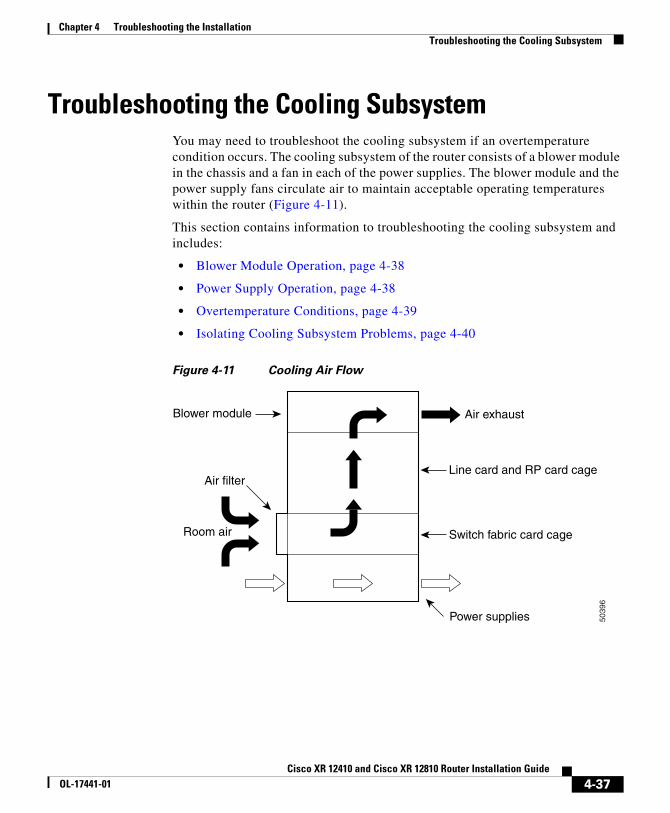
Troubleshooting the Cooling SubsystemYou may need to troubleshoot the cooling subsystem if an overtemperature condition occurs. The cooling subsystem of the router consists of a blower module in the chassis and a fan in each of the power supplies. The blower module and the power supply fans circulate air to maintain acceptable operating temperatures within the router (Figure 4-11).
This section contains information to troubleshooting the cooling subsystem and includes:
• Blower Module Operation, page 4-38
• Power Supply Operation, page 4-38
• Overtemperature Conditions, page 4-39
• Isolating Cooling Subsystem Problems, page 4-40
Figure 4-11 Cooling Air Flow
Air exhaust
Line card and RP card cage
Room air
Air filter
Switch fabric card cage
Blower module
Power supplies 5039
6
4-37Cisco XR 12410 and Cisco XR 12810 Router Installation Guide
OL-17441-01
Chapter 4 Troubleshooting the InstallationTroubleshooting the Cooling Subsystem
Blower Module OperationThe blower module maintains acceptable operating temperatures for the internal components by drawing cooling air through a replaceable air filter into the switch fabric and alarm card cage, and then through the line card and RP card cage (see Figure 4-11). The blower module occupies a bay at the top of the router and receives power from the chassis backplane through a wiring harness.
The blower module contains three fans, a controller card, and two front panel status LEDs. A snap-on plastic front cover fits over the front panel, but the LEDs are visible through the front covers.
– Green—The blower module is functioning properly.
– Red—There is a fault detected in the blower module.
• If the air temperature inside the chassis rises, blower speed increases to provide additional cooling air to the internal components.
• If the internal air temperature continues to rise beyond the specified threshold, the system environmental monitor shuts down all internal power to prevent equipment damage due to excessive heat.
• If the system detects that one or more of the fans in the blower module has failed, it displays a warning message on the system console and displays a blower failure message on the RP alphanumeric display. In addition, the remaining fans go to full speed to compensate for the loss of the failed fan.
Power Supply OperationEach AC or DC power supply is equipped with a fan that draws cooler air in through the front of the power module and forces warmer out the back of the power shelf.
• If the power source is within the required range, the power supply fan remains on.
• If the fan fails:
– Power supply detects an internal overtemperature condition
– Fault and Temp indicators light
– Power supply sends an overtemperature warning to the system and then shuts down the system.
4-38Cisco XR 12410 and Cisco XR 12810 Router Installation Guide
OL-17441-01
Chapter 4 Troubleshooting the InstallationTroubleshooting the Cooling Subsystem
For additional power supply troubleshooting information, see the “Troubleshooting the Power Subsystem” section on page 4-5
Overtemperature ConditionsThe following console error message indicates that the system has detected an overtemperature condition or out-of-tolerance power value inside the system:
Queued messages:%ENVM-1-SHUTDOWN: Environmental Monitor initiated shutdown
The preceding message could also indicate a faulty component or temperature sensor. Enter the show environment command or the show environment all command at the user EXEC prompt to display information about the internal system environment. The information generated by these commands include:
• Voltage measurements on each card from the DC-to-DC converter
• The +5 VDC for the MBus module
• The operating voltage for the blower module.
• Temperature measurements received by two sensors on each card (one for inlet air temperature and one for the card’s hot-spot temperature), as well as temperature measurements from sensors located in each power supply.
If an environmental shutdown results from an overtemperature or out-of-tolerance condition, the Fault indicator on the power supply lights before the system shuts down.
Although an overtemperature condition is unlikely at initial system startup, make sure that:
• Heated exhaust air from other equipment in the immediate environment is not entering the chassis card cage vents.
• You allow sufficient air flow by maintaining a minimum of 6 inches (15.24 cm) of clearance at both the inlet and exhaust openings on the chassis and the power modules to allow cool air to enter freely and hot air to be expelled from the chassis.
4-39Cisco XR 12410 and Cisco XR 12810 Router Installation Guide
OL-17441-01
Chapter 4 Troubleshooting the InstallationTroubleshooting the Cooling Subsystem
Isolating Cooling Subsystem ProblemsUse the following procedure to isolate a problem with the chassis cooling system if you have an overtemperature condition.
Step 1 Make sure the blower module is operating properly when you power on the system.
• To determine if a blower module is operating, check the two LED indicators on the blower module front panel:
– OK (green)—The blower module is functioning properly and receiving –48 VDC power, indicating that the cables from the chassis backplane to the blower module are good.
– Fail (red)—A fault is detected in the blower module. Replace the blower module.
– If neither indicator is on and the blower is not operating, there may be a problem with either the blower module or the –48 VDC power supplied to the blower module. Go to Step 2.
Step 2 Eject and reseat the blower module making sure the captive screws are securely tightened.
If the blower module still does not function, go to Step 3.
Step 3 Check for –48 VDC power by looking at the LED indicators on each power supply:
• If the Pwr OK indicator is on and the Fault indicator is off on each power supply, it indicates that the blower is receiving –48 VDC.
– If the blower module is still not functioning, there could be a problem with the blower module controller card or an undetected problem in the blower module cable. Replace the blower module.
– If the new blower module does not function, contact a Cisco customer service representative for assistance.
• If the Fault indicator is on, the power supply is faulty. Replace the power supply.
4-40Cisco XR 12410 and Cisco XR 12810 Router Installation Guide
OL-17441-01
Chapter 4 Troubleshooting the InstallationTroubleshooting the Cooling Subsystem
• If the Temp and Fault indicators are on, an overtemperature condition exists.
– Verify that the power supply fan is operating properly.
– If the fan is not operating, replace the power supply.
Contact your Cisco representative if replacing the power supply does not fix the problem.
4-41Cisco XR 12410 and Cisco XR 12810 Router Installation Guide
OL-17441-01
Chapter 4 Troubleshooting the InstallationTroubleshooting the Cooling Subsystem
4-42Cisco XR 12410 and Cisco XR 12810 Router Installation Guide
OL-17441-01