Embed Size (px)
Citation preview

Troubleshooting
STAR TRAC FITNESS 1 637-1383 Rev: A
Treadmill Embedded Touch Screen Won’t Power Up
E-TRe and E-TRxe This document contains the necessary information to troubleshoot a treadmill with an embedded touch screen that will not power up. Follow the flowchart on the next page. All documents referenced in the flow chart are also included.

Verify that the treadmill plugged into the wall and
the power switch is set to the ‘on’
position?
Unit plugged in and power switch on?
Disconnect the power cord from the underside of the treadmill and
reconnect it. Also verify that the cord is secured with the tie strap.
(See 637-1308)
Yes
Verify that there is power coming
from the wall. Either 110 VAC
or 220 VAC
Plug the treadmill into the wall outlet and turn the power switch to the ‘on’ position and test.
No Does the screen turn on?
No
Treadmill is operational.Yes
Is there sufficient
voltage from the wall?
Yes
Check the wall breaker. Make
sure the breaker has not tripped
off..
NoWas the
breaker tripped off?
Turn the breaker on so power is
coming from the outlet and test the
treadmill.
Yes
Does the screen turn on?
Treadmill is operational.Yes
No
Does the screen turn on?
Yes
Remove the motor shroud. Check the MCB to see if any
lights are on.
No
Are the MCB lights on? No
The outlet is at fault. Plug the treadmill into another outlet.No
MCB Will Not Power Up(637-1378)
Yes
The MCB may not be getting power or is faulty. Follow the procedures in “MCB Will Not Power Up”
Verify that the breaker on the
treadmill has not been tripped.
Was the breaker tripped?
No
Push the breaker in to reset and test
the unit.
Does the screen turn on? YesTreadmill is
operational. Yes
No
Pg. 2Ver. 1 Ver 1
Determine the version of the MCB inside the treadmill.
(See 637-1338)
Version 1 or Version 2
Pg. 2Ver. 2
Ver 2

Ver. 2
The screen may need to be manually reset. Follow procedures in “Manual Computer
Reset”
Manual Computer
Reset(637-1382)
Does the screen turn on?
The treadmill is operational.
Replace the embedded screen and return failed
display to Star Trac.
Yes
No
Without an external power supply, multiple checks will need to be made. Follow procedures in “Checking the Power Supply and
Power Cables”
No
Verify that the LED on the power
supply board is on.Is the LED on?
Checking the Power Supply
(637-1379)No
The power supply may not be getting power or
is faulty. Follow procedure in “Checking
the Power Supply”
The next trouble shooting step will require an
external power supply.
Test the Embedded Screen
with an External Power Supply
(637-1380)
Yes
Ver. 1
Is external supply available? Yes
Checking the Power Supply
and Power Cables
(637-1381)
No
Does the screen turn on?
Yes
Does the screen turn on?
The treadmill is operational. Yes
The screen is good. Multiple checks will need to be made to
determine the root cause. Follow procedures in “Checking the
Power Supply and Power Cables”
Checking the Power Supply
and Power Cables
(637-1381)
The treadmill is operational.

Customer Services Bulletin
STAR TRAC FITNESS 1 of 1 637-1308 Rev: A
Treadmill Power Cord Tie Wrap
E Series & S Series Treadmills Star Trac recommends securing the power cord on the E Series and S Series treadmills with a tie wrap (zip tie). This will prevent intermittent power issues caused when the power cord become loose in the connector. Step 1
Make sure the power cord connector it securely plugged in to the treadmill (Fig. 1). Raise the treadmill incline to 15% (or high enough to give you room to work underneath). Once elevated, turn the power switch Off, so the unit does not automatically come back down while you are working underneath.
Step 2
You may need to open the motor shroud. You will need to loop a tie wrap (zip tie) up and back down through two holes to hold the power cord connector into place (Fig. 2).
Fig. 1
Fig. 2
Step 3
Make sure the power cord is routed out the front of the treadmill (Fig. 3) and will be out of the way of the unit’s normal operation. Make sure the power cord has enough slack so that the treadmill can incline and decline without tension on the power cord. Cut the excess tie wrap (Fig. 4)
Fig. 3
Fig. 4
Test unit for proper function.
General Information
STAR TRAC FITNESS 1 of 8
637-1338 Rev: B
MCB Changes
All AC Motor System Treadmills:
Starting August 2010 there will be a change of the MCB.
• New P/N 715-3881 for 110 volt systems
• New P/N 715-3880 for 220 volt systems Some components on the old system have been designed into the new MCB and are no longer needed. This document explains the changes that have been made and the difference between the old and new system.
Components Not Needed with New MCB
The following diagrams (Fig. 1 and 2) show the old system and have the parts highlighted that won’t be part of the new
system. Figure 3 shows the wiring diagram of the old system.
• Resistors and Brackets (Items No. 21, P/N: 715-3588 and Item No. 15, P/N: 170-0688)
• Power Supply (Item No. 25, P/N: 715-3784)
• Fan Cable (Item No. 24, P/N 715-3674)
Fig. 1

General Information
STAR TRAC FITNESS 2 of 8
637-1338 Rev: B
Fig. 2

General Information
STAR TRAC FITNESS 3 of 8
637-1338 Rev: B
Fig.3

General Information
STAR TRAC FITNESS 4 of 8
637-1338 Rev: B
New AC System: The new MCB’s are backwards compatible with all AC Motor System Treadmill:
• P-Series 7600/7700 (still requires the FCB “Fan Control Board” and the cable that goes from the FCB to the MCB)
• E-Series Treadmills
• S-TRc Treadmill If you use the new MCB to replace the old version you may leave the unnecessary components unplugged (resistors and power supply) on the motor pan.
Serial Number Cut In for 110V units: E-TR/E-TRe
• TREN1008-U21673 and up E-TRx/E-TRxe
• TREX1008-U21673 and up S-TRc serial number cut in:
• Not available as of today
Serial Number Cut In for 220V units: E-TR/E-TRe
• TREN1008-U21250 to TREN1008-U21254
• TREN1008-U21276 and up E-TRx/E-TRxe
• TREX1008-U21276 and up S-TRc serial number cut in:
• Not available as of today

General Information
STAR TRAC FITNESS 5 of 8
637-1338 Rev: B
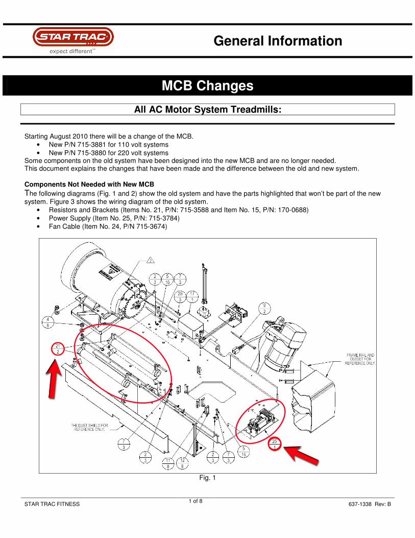
Figure 4 and 5 below show a drawing of the new system followed by Figure 6 which shows the wiring diagram of the new system (110V/220V).
Fig. 4
General Information
STAR TRAC FITNESS 6 of 8
637-1338 Rev: B
Fig. 5

General Information
STAR TRAC FITNESS 7 of 8
637-1338 Rev: B
Fig. 6

General Information
STAR TRAC FITNESS 8 of 8
637-1338 Rev: B
You may encounter some MCB’s where the connector that delivers power to the PVS or embedded head (see actual location of this connector in Fig. 7 below) has 6 pins but the connector that plugs in is only a 4 pin connector. In this case plug the connector into the middle and keep one pin on the left and one pin on the right free (Fig. 8). Carefully cut the two outer pins to prevent future confusion.
Always turn the unit off and unplug it from the wall power outlet before working on any electronic component.
Fig. 7
Fig. 8

Troubleshooting
STAR TRAC FITNESS 1 of 4 637-1378 Rev: A
MCB Will Not Power Up
AC MCB’s
The following document outlines the troubleshooting steps to determine why an MCB is not powering up (or there are no diagnostic LED turned on). The main symptom is that the display or embedded touch screen will not turn on.
The procedures in this troubleshooting document require the power to be on and the drive motor shroud to be removed. Take extreme caution when working around live electronic components. If you are not comfortable
working around electricity, do no perform this procedure. Some assumptions have been made as well:
• The power cord is securely plugged into a wall outlet.
• The outlet is supplying the appropriate amount of AC voltage.
• The other end of the power cord is secured in the unit.
• The power switch is set ‘on’ and/or the breaker on the treadmill has not been tripped. Do not continue with the rest of the document until these have been confirmed. The following tools will be needed:
• Phillips screwdriver
• Multi-meter
Verify Power Coming from EMI Filter 1. Turn the power switch to the off position. 2. Locate the EMI Filter (Fig. 1) and disconnect the two wires that go to the MCB (Fig. 2).
Fig. 1
Fig. 2

Troubleshooting
STAR TRAC FITNESS 2 of 4 637-1378 Rev: A
Warning: The following procedures require the power to be on. Take extreme caution when working around live electrical components.
3. Turn the power switch on. 4. Set the multi-meter to read AC power and check the voltage coming out of the EMI Filter (Fig. 3). The readings
should be between:
• 110 Volt Treadmills – 110 VAC – 120 VAC
• 220 Volt Treadmills – 208 VAC – 240 VAC
Fig. 3
• If there is no power coming from the EMI filter, turn the power switch to off. Reconnect the wires then go to step 5.
• If there is power, turn the power switch off, reconnect the wire and go to the section: Verifying Power Going to the MCB.
5. Disconnect the cables (brown and blue) from the input side of the EMI filter (Fig. 4).

Troubleshooting
STAR TRAC FITNESS 3 of 4 637-1378 Rev: A
Warning: The following procedures require the power to be on. Take extreme caution when working around live electrical components.
6. Insert the multi-meter leads into the cables (Fig. 5) then turn the power on. The voltage reading should be like
those noted in step 4.
Fig. 4
Fig. 5
a. If there is voltage, replace the EMI filter. Then test the treadmill to see if the MCB will power up. b. If there is no voltage, replace the on/off switch and/or the onboard circuit breaker. Then test the
treadmill to see if the MCB will power up. If the MCB will not power up after replacing components, continue on to section: Verifying Power Going to the MCB.
Warning: The following procedures require the power to be on. Take extreme caution when working around live electrical components.
Verify Power Going to the MCB 1. With the power on, check the voltage on P6 on the MCB (Fig. 6). This is the main power to the MCB from the EMI
filter. The readings should be between:
• 110 Volt Treadmills – 110 VAC – 120 VAC
• 220 Volt Treadmills – 208 VAC – 240 VAC

Troubleshooting
STAR TRAC FITNESS 4 of 4 637-1378 Rev: A
Fig. 6
• If there is no power, replace the power cable then test the unit.
• If the MCB LED’s still are not on, continue on to section: Check the Fuse on the MCB.
Check the Fuse on the MCB 1. Turn the treadmill off. 2. Remove fuse F1 from the MCB (Fig. 7) and with the multi-meter, check the fuse (Fig. 8). There should be
continuity across the fuse.
Fig. 7
Fig. 8
If the fuse has no continuity or is visibly burnt, replace the fuse. It is a 250v .4 amp (400 milliamps) slow blow fuse. Once replaced test to see if the MCB powers up.
• If the MCB does not power up after replacing the fuse, replace the MCB.
• If the fuse is good and the MCB won’t power up, replace the MCB.

Troubleshooting
STAR TRAC FITNESS 1 of 3 637-1379 Rev: A
Checking the Power Supply
E-TR, E-TRx, E-TRe, & E-TRxe
Version 1 MCB The Version 1 MCB of the E Series treadmills have an external power supply that is used to send 12 volts of DC power to the following components :
• Fans for the LED display
• PVS System
• Embedded Touch Screen Tools Needed:
• Phillips screwdriver
• Multi-meter
Warning: The following procedures require the power to be on. Take extreme caution when working around live electrical components.
If any of these components are not powering up follow the steps below to verify is the power supply is working.
1. Turn the unit power on. 2. Lift the motor shroud and visually check the power supply to ensure that there is an LED (Fig. 1) lit. This LED will
be lit when there is voltage being supplied to board and the board is in working order.
Fig. 1

Troubleshooting
STAR TRAC FITNESS 2 of 3 637-1379 Rev: A
If the LED is not lit, disconnect the four pin cable from the power supply (Fig. 2) to see if the light comes back on.
Fig. 2
• If the light comes on, then there is a short somewhere in the system above. The power supply is functioning properly.
• If the light does not come on, go to step 3. 3. Set the multi-meter to read AC voltage. Insert the leads into connector of the brown and blue wires (Fig. 3). Be
sure the leads are in contact with the pins inside the connector housing. There should be 120 VAC (or 220 VAC) coming into the board.
Fig. 3
• If there is 120 VAC (or 220 VAC), but the power supply LED is not lit, replace the power supply.
• If there is not sufficient power, continue to step 4.

Troubleshooting
STAR TRAC FITNESS 3 of 3 637-1379 Rev: A
Warning: The following procedures require the power to be on. Take extreme caution when working around live electrical components.
4. Disconnect the power supply cable (P1) from the MCB (Fig. 4). Set the multi-meter to read AC voltage. Put one
lead on pin 1 and the other on pin 3 (Fig. 5). There should be 120 VAC (or 220 VAC).
Fig. 4
Fig. 5
• If there is no voltage coming from the MCB, yet the MCB diagnostic LED’s are lit, replace the MCB.
• If there is voltage coming from the MCB, the replace the power supply cable.

Troubleshooting
STAR TRAC FITNESS 1 of 2 637-1380 Rev: A
Test An Embedded Screen with External Power Supply
E-TRe & E-TRxe When troubleshooting an embedded touch screen that won’t power up, using an external 12 VDC power supply is the fastest way to determine if the screen is working. The following procedure explains how to use the external power supply. Note: This document is used as part of the “Embedded Touch Screen Won’t Power Up” flowchart.
Use an External Power Supply Use a separate 12 volt DC power supply (Fig. 1) and an adaptor cable (Fig. 2). The power supply from an E Series bike embedded touch screen or PVS kit would work. The adaptor cable can be obtained from Star Trac.
Fig. 1
Fig. 2

Troubleshooting
STAR TRAC FITNESS 2 of 2 637-1380 Rev: A
1. Remove bottom cover of the display housing (Fig. 3) to gain access to the interface board of the embedded touch
screen (Fig. 4).
Fig. 3
Fig. 4
2. Connect the external power supply to the adaptor cable (Fig. 5) and then plug the other end of the adaptor cable into the embedded screen (Fig. 6). Then plug the power supply into the wall (Fig. 7).
Fig. 5
Fig. 6
Fig. 7
3. Watch to see if the embedded touch screen will power up then return to the troubleshooting flowchart.

Troubleshooting
STAR TRAC FITNESS 1 of 7 637-1381 Rev: A
Checking the Power Supply and Power Cables
E Series Treadmills
This document contains troubleshooting for both Version 1 and Version 2 MCB’s. These procedures will require the motor shroud to be removed.
Warning: The following procedures require the power to be on. Take extreme caution when working around live electrical components.
Version 1 MCB If an embedded treadmill display will not power up, yet there appears to be power on the power supply, follow the steps outlined in this document. Tools Needed:
• Phillips screwdriver
• Multi-meter
• Small flathead screwdriver Note: The procedures in this troubleshooting document require the power to be on and the drive motor shroud to be removed. Take extreme caution when working around live electronic components.

Troubleshooting
STAR TRAC FITNESS 2 of 7 637-1381 Rev: A
Check the Power Supply 1. Check the power supply to see if the LED is lit (Fig. 1).
• If the LED is off, refer to document Checking the Power Supply (doc number: 637-1379) for troubleshooting instructions.
• If the LED is on, continue on to step 2.
Fig. 1
2. Visually inspect the power cable connection at the power supply. Check for burned or charred marks on the
plastic connector (Fig. 2).
Fig. 2
• If there are burn marks on the connector, the cable must be replaced.
• If there are no burn marks on the connector, go to step 3.
Warning: The following procedures require the power to be on. Take extreme caution when working around live electrical components.
3. Set the multi-meter to read DC voltage and take a reading between pins 1 (white) and 3 (black) (Fig. 3).The leads
must be in contact with the pin in the plastic connector to get a proper reading. There should be approximately 12 volts DC.

Troubleshooting
STAR TRAC FITNESS 3 of 7 637-1381 Rev: A
Fig. 3
• If there is no voltage, replace the power supply.
• If there is 12 volts, continue to Check the Connector at Screen or PVS CCB
Check the Connector at the Screen or PVS CCB 1. Visually inspect the power cable connection at the embedded screen/PVS CCB. Check for burned or charred
marks on the plastic connector (Fig. 4).
Fig. 4
• If there are burn marks on the connector, the cable must be replaced.
• If there are no burns on the connector, continue to Verify Voltage to the Screen or PVS CCB

Troubleshooting
STAR TRAC FITNESS 4 of 7 637-1381 Rev: A
Verify Voltage to the Screen or PVS CCB 1. Set the multi-meter to read DC voltage. Insert the leads into the plastic connector (Fig. 5). The leads must be in
contact with the pin in the plastic connector to get a proper reading. There should be at least 11 VDC.
Fig. 5
• If the voltage is less than 10.4 volts DC, replaced the power cable.
• If the voltage is between 10.5 and 10.9 volts leave the multi-meter leads in the plastic connector and continue to Adjusting the Power Supply Potentiometer
Adjusting the Power Supply Potentiometer 1. Locate the potentiometer (pot) on the power supply (Fig. 6).
Fig. 6
2. Using the small flathead screwdriver, make small adjustments in the counter-clockwise direction and watch the
multi-meter. Turn the pot till the meter reads 11.2 volts.

Troubleshooting
STAR TRAC FITNESS 5 of 7 637-1381 Rev: A
Version 2 MCB 1. Visually inspect the power cable connection at the MCB (Fig. 7). Check for burned or charred marks on the plastic
connector (Fig. 8).
Fig. 7
Fig. 8
• If there are burn marks on the connector, the cable must be replaced.
• If there are no burn marks on the connector, go Check the Connector at the Screen or PVS CCB
Check the Connector at the Screen or PVS CCB 1. Visually inspect the power cable connection at the embedded screen/PVS CCB. Check for burned or charred
marks on the plastic connector (Fig. 4).
Fig. 4
• If there are burn marks on the connector, the cable must be replaced.
• If there are no burns on the connector, continue to ‘Checking Power at the MCB’

Troubleshooting
STAR TRAC FITNESS 6 of 7 637-1381 Rev: A
Warning: The following procedures require the power to be on. Take extreme caution when working around live electrical components.
Check Power at the MCB 1. Set the multi-meter to read DC voltage and take a reading between white and black wires (Fig. 9). The leads must
be in contact with the pin in the plastic connector to get a proper reading. There should be approximately 12 volts DC.
Fig. 9
• If there is no voltage, and the diagnostic LED’s are lit, replace the MCB.
• If there is voltage, continue on to Verify Voltage to the Screen or PVS CCB.

Troubleshooting
STAR TRAC FITNESS 7 of 7 637-1381 Rev: A
Warning: The following procedures require the power to be on. Take extreme caution when working around live electrical components.
Verify Voltage to the Screen or PVS CCB 1. Set the multi-meter to read DC voltage. Insert the leads into the plastic connector (Fig. 10). The leads must be in
contact with the pin in the plastic connector to get a proper reading. There should be at least 11 VDC.
Fig. 10
• If the voltage is below 11 VDC, replace the power cable.

Troubleshooting
STAR TRAC FITNESS 1 of 4 637-1382 Rev: A
Manual Computer Reset
Embedded Touch Screen
If the embedded touch screen does not appear to be powering up (black screen and no fan running), follow the steps below for proper troubleshooting: 1. Check if the 2 pin connector (JP10) on the interface board (PN: 718-5166) has a solid connection (Fig. 1 and 2). Re-
seat it and check if the plastic body that is attached to the board bonded with it to ensure contact. The interface boards function is to pass the signal/power coming in through to the inside components of the computer.
Fig. 1
Fig. 2

Troubleshooting
STAR TRAC FITNESS 2 of 4 637-1382 Rev: A
2. Remove the metal box enclosing the computer. 3. Locate the jumper header as shown in Fig. 3 and 4.
Fig. 3

Troubleshooting
STAR TRAC FITNESS 3 of 4 637-1382 Rev: A
Fig. 4

Troubleshooting
STAR TRAC FITNESS 4 of 4 637-1382 Rev: A
4. Power the computer by attaching it back into the unit and turning on the power or using an external power source (12
VDC) 5. Momentarily short the two pins on the jumper header as shown in the pictures below using a flat head screwdriver.
Fig. 3
6. The computer will turn on. After a few seconds the computer will beep once.
7. Turn off the power to the unit.
8. Turn on the power to the unit and after a few seconds the computer should power on.
9. Steps 7 and 8 can be repeated and each time the computer should power on.
10. Once this is done, replace the metal box on the computer and re-assemble the unit.
11. Power up the unit and run a workout to ensure proper function.