Embed Size (px)
Citation preview

TRP 9946Properties of Galvanized and Galvannealed Advanced High Strength Hot Rolled Steels
Report atAISI / DOE TRP Industry Briefing Session
October 10, 2007Salt Lake City, Utah

Project Participants
Research Organizations:CANMET–Materials Technology Laboratory, Ottawa, Canada McGill University, Montreal, CanadaMcMaster University, Hamilton, Canada
Industry Participants:International Lead Zinc Research Organization (ILZRO)Nucor Steel, SCSeverStal N.A., Dearborn, MIUS Steel, Pittsburgh, PA
2

Project Team
CANMET–Materials Technology LaboratoryVal Guertsman (Project Leader) Réal Bouchard Elhachmi Essadiqi (Program Manager) Pierre Martin Olga Dremailova Benoit Voyzelle
International Lead Zinc Research OrganizationFrank Goodwin
McGill UniversityJames Nemes, Wael Dabboussi
McMaster UniversityJoe McDermid, Richard Fourmentin
3

Objectives
This project addresses three technical hurdles for implementation of galvanized and galvannealed advanced high strength hot rolled steels for automotive applications :
achievement of good quality coatings on the hot rolled steels while retaining target mechanical propertieslack of precise knowledge of the behavior of these steels in the various forming operations required by automobile parts manufacturersdevelopment of accurate user property data in the galvanized and galvannealed conditions
4

Project Tasks
The project was scheduled to be completed in two years following the kick-off meeting (start date July 1, 2005).At the AISI Project Review Meeting on February 8, 2007 in Ottawa it was agreed to revise the work plan and schedule, and extend the end date to the end of December 2007.
Task/Sub-Task Description A Galvanizing Simulator Trials A.1. Obtaining the Steels A.2. Hot Dip Galvanizing A.3. Galvannealing B. Formability Evaluation B.1. Stretch-Flange-Formability B.2. Tube Welding B.3. Hydroforming CharacteristicsC. User Properties C.1. Fatigue C.2. Dynamic Tensile Testing D. Reporting
5

Obtaining Steel SubstratesThree grades of advanced high strength hot rolled steel with thickness 2.0-2.5 mm were envisaged in the project planThe following materials were received for the project:
HSLA (composition similar to alternative HSLA grade) – delivered in February 2006DP (composition close to alternative DP grade) – delivered in December 2005TRIP (composition somewhat similar to alternative TRIP grade) – delivered March 30, 2007
Composition (wt.%) Target Properties Type
C Si Mn Nb Ti Other Y. S. (MPa)
T. S. (MPa)
Total El. (%)
HSLA 0.08 0.01 0.54 0.04 0.05 - 570 620 23 Alternative HSLA grade
0.06-0.08
0.01-0.14
0.5-1.4
Precipitation strengthening based on Ti, Nb and/or V
TRIP 0.18 1.5 1.4 0.025 0.005 - 500 900 20
Alternative TRIP grade 0.1-0.2 0.5-1.5 <1.5
0.05 to 1.0 Al (depending on Si content) Nb and/or P to obtain desired strength level
DP* 0.08 <0.3 1.5 0.03 0.002 0.25 Mo, 0.5 Cr 350 600 20
Alternative DP grade <0.1 1.6-
2.0 Nb, Cr and/or Mo additions
6

HSLA Steel: As-received Hot Rolled Steel
Uniform microstructure:Fine-grained ferrite interspersed with a few pearlite grainsSmall volume fraction of pearliteFine GB carbidesComplex oxide and sulfide inclusions up to 10 microns in diameter
Mechanical properties conform to the target properties
Optical metallography (OM) Scanning electron microscopy (SEM)
7

Hot Dip Galvanizing of HSLA Steel38 coupons were galvanized at McMaster University and delivered to CANMET for further tests
side 1 side 2
88 cm
20 c
m
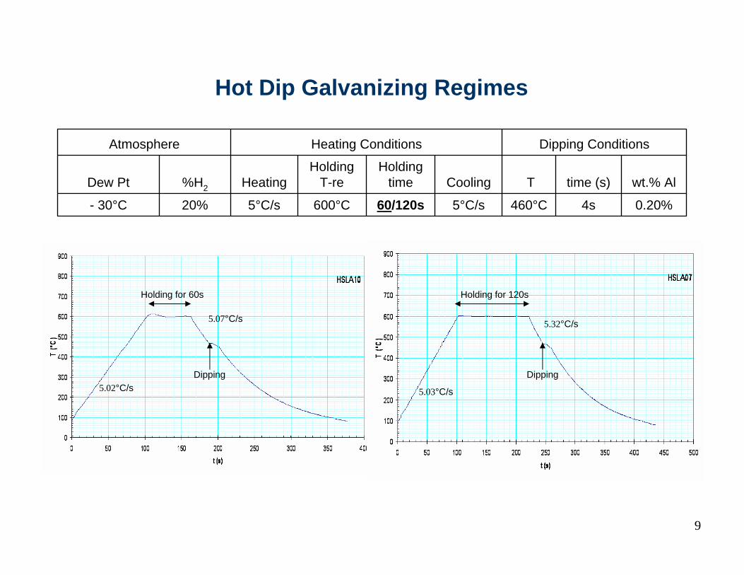
Hot Dip Galvanizing Regimes
0.20%4s460°C5°C/s60/120s600°C5°C/s20%- 30°C
wt.% Al time (s) T Cooling Holding
timeHolding
T-reHeating %H2Dew Pt
Dipping ConditionsHeating ConditionsAtmosphere
5.02°C/s
Holding for 60s
5.07°C/s
5.03°C/s
5.32°C/s
Dipping Dipping
Holding for 120s
9
Summary on Galvanizing Simulator Trials for HSLA Steel
Two thermal cycles were tested for the HSLA steel, 60s and 120s holding times at 600°C.
These two regimes resulted in similar characteristics in terms of the obtained microstructure, and the quality of the coating and the inhibition layer.
According to recommendations of the sponsors, the holding time of 60 s was chosen.
38 coupons were galvanized at McMaster University and delivered to CANMET-MTL for further tests.
10

Galvannealing of HSLA Steel24 coupons were galvannealed at McMaster University and delivered to CANMET for further tests
side 1 side 2
118 cm
20 c
m

Optimal Galvannealing ParametersReheating atmosphere 20% H2 in N2 with a dew point of -30°CZinc bath with 0.123% effective Al and Fe saturatedGalvannealing temperature = 510°CGalvannealing time = 30 s
Example of thermal cycle
510°C – 30s
12
Holding for 60s
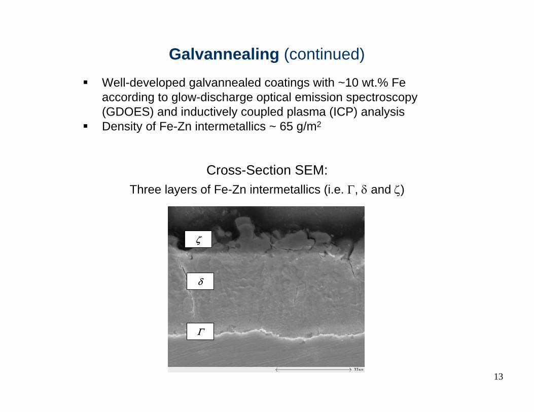
Cross-Section SEM:
ζ
Three layers of Fe-Zn intermetallics (i.e. Γ, δ and ζ)
Γ
δ
Galvannealing (continued)
Well-developed galvannealed coatings with ~10 wt.% Fe according to glow-discharge optical emission spectroscopy (GDOES) and inductively coupled plasma (ICP) analysisDensity of Fe-Zn intermetallics ~ 65 g/m2
13

Tensile Properties of HSLA Steel
Mechanical properties retained after galvanizing and galvannealing~ correspond to target properties
0.0726±1635±3598±9Longitudinal
0.0725±1646±1616±4TransverseGalvannealed
0.0829±1632±1590±5Longitudinal
0.0728±1647±2608±8TransverseGalvanized
0.0922±1633±2580±5Longitudinal
0.0719±1654±13613±12TransverseAs-received(hot-rolled)
Strain hardening
n
Total Elongation
(%)
Ultimate Tensile Stress(MPa)
Stress at 0.2% Offset
(MPa)OrientationCondition
14

Stretch-Flange Formability
According to ISO/TS 16630:2003
Force a conical die through a pre-punched hole until any one crack extends through the test piece thickness
Hole Expansion Test
15

Stretch-Flange Formability of Galvanized HSLA SteelSix galvanized HSLA coupons testedThe hole expansion ratio λ = 67.4 ± 5.2 %
Jan.29/07 60 Degree Cone PunchSERIAL Dia.-Org. Dia. - Final Avg. %Stretch GaugeHSLA 25 0.3975 0.6940 0.6980 0.6970 0.6965 0.6964 75.2 0.1031HSLA 36 0.3975 0.6485 0.6470 0.6480 0.6475 0.6478 63.0 0.1051HSLA 41 0.3975 0.6835 0.6830 0.6840 0.6835 0.6835 71.9 0.1045HSLA 60 0.3975 0.6575 0.6560 0.6565 0.6570 0.6568 65.2 0.1033HSLA 46 0.3970 0.6435 0.6415 0.6425 0.6420 0.6424 61.8 0.1029HSLA 32 0.3970 0.6640 0.6655 0.6645 0.6650 0.6648 67.4 0.1023
Avg. 0.6653 67.4St.Dev. 0.0210 5.24
Example of galvanized coupon after hole expansion test
16
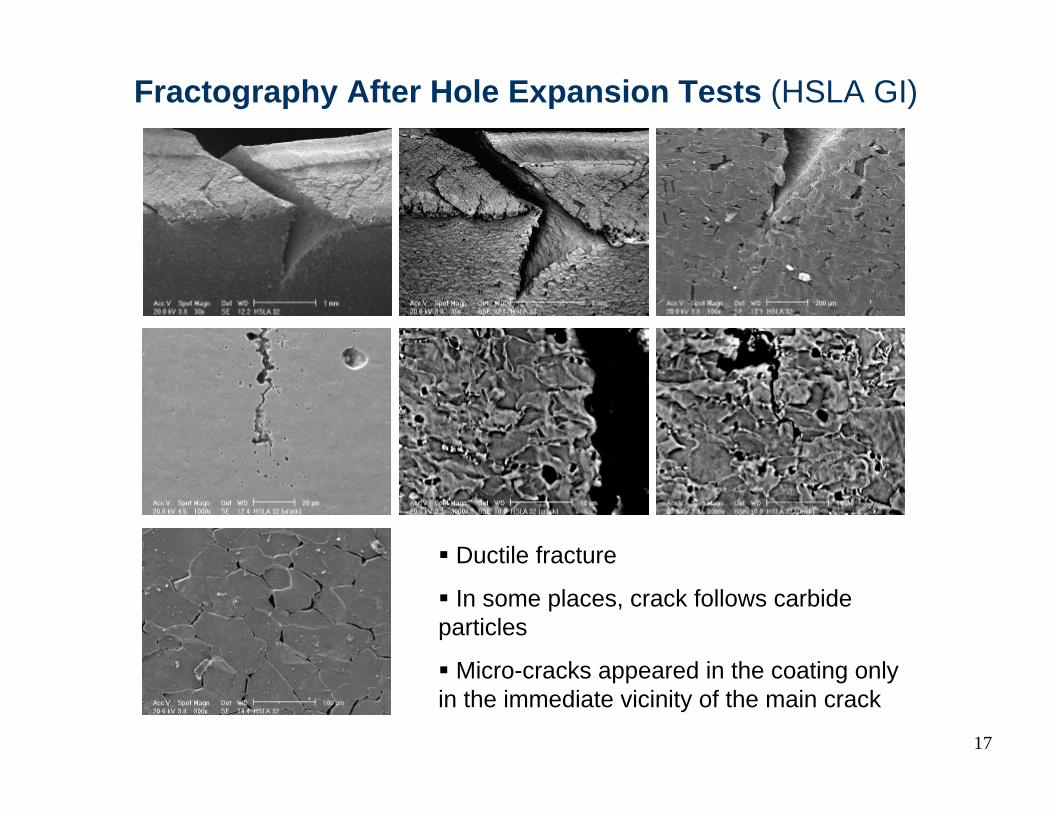
Fractography After Hole Expansion Tests (HSLA GI)
Ductile fracture
In some places, crack follows carbide particles
Micro-cracks appeared in the coating only in the immediate vicinity of the main crack
17

Stretch-Flange Formability of Galvannealed HSLA SteelFive galvannealed HSLA coupons testedThe hole expansion ratio λ = 34.7 ± 2.5 %
Example of galvannealed coupon after hole expansion test
May14/07 60 Degree Cone PunchSERIAL Dia.-Org. Dia. - Final Avg. %StretchGA 30 0.3965 0.5440 0.5425 0.5435 0.5445 0.5436 37.1GA 33 0.3965 0.5260 0.5270 0.5255 0.5270 0.5264 32.8GA 35 0.3970 0.5315 0.5290 0.5315 0.5310 0.5308 33.7GA 36 0.3970 0.5460 0.5455 0.5470 0.5465 0.5463 37.6GA 37 0.3965 0.5255 0.5235 0.5265 0.5240 0.5249 32.4
Avg. 0.5344 34.7St.Dev. 0.0099 2.47
18

Fractography After Hole Expansion Tests (HSLA GA)
Substrate material appears to be more brittle with GA coating than galvanized
GA coating is cracked all over bended parts
19
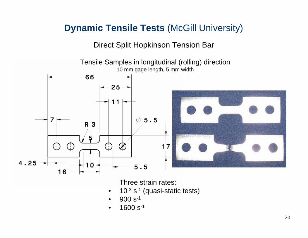
Dynamic Tensile Tests (McGill University)
Direct Split Hopkinson Tension Bar
Tensile Samples in longitudinal (rolling) direction10 mm gage length, 5 mm width
Three strain rates:• 10-3 s-1 (quasi-static tests)• 900 s-1
• 1600 s-1
20

Dynamic Tensile Testing:Examples of Stress-Strain Curves
0
100
200
300
400
500
600
700
800
900
1000
0 0.05 0.1 0.15 0.2 0.25 0.3 0.35 0.4
Eng. Strain
Eng.
Stre
ss (
MPa
)QS Ten HGZ 0.001 /s
Dyn Ten HGZ 1000 /s
Dyn Ten HGZ 1600 /s
21

Summary Results of Dynamic Tensile Tests
287351600 s-1
27735900 s-1
3765810-3 s-1
HSLA Galvannealed
267401600 s-1
27698900 s-1
3663810-3 s-1
HSLA Galvanized
Total Elongation (%)UTS (MPa)Strain Rate
The results indicate an increase in stress at higher strain rates coupled with a small decrease in total elongation to failure. The energy absorbed at high strain rates is above that at quasi-static rate, and similar in the GI and GA conditions.
22
14210770.914010872.31600 s-1
14310871.513810570.2900 s-1
12794.561.212390.659.310-3 s-1
at 20 % strainat 15 % strainat 10 % strainat 20 % strainat 15 % strainat 10 % strainStrain Rate
Galvannealed (N/m2)Galvanized (N/m2)
Absorbed Energy

Fractography After Dynamic Tensile Tests
Somewhat different appearance on macro-scale
Similar ductile fracture on micro-scale
Quasi-static tests Dynamic tests
23

Several panels were provided, but not enough to finish all the tasks planned in the project.Additional quantity of this steel could not be received.In the as-received condition the steel did not have characteristic DP microstructure.Mechanical properties of the steel in the as-received condition did not conform to the requirements.
24
Dual-Phase Steel
Representative stress-strain curve for the as-received hot rolled DP steel showing yield point elongation behavior
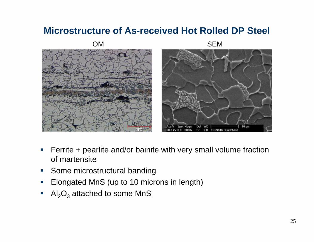
Microstructure of As-received Hot Rolled DP Steel
Ferrite + pearlite and/or bainite with very small volume fraction of martensiteSome microstructural bandingElongated MnS (up to 10 microns in length)Al2O3 attached to some MnS
OM SEM
25

Additional Heat Treatment of DP Steel
26
Dilatometer trials have determined reheating schedules producing ferrite + martensite microstructure:
188±14.4±0.3438688950°C/5 min 50°C/sDP438
201±24.6±0.3481761950°C/5 min 50°C/sDP255
177±24.8±0.3490716950°C/5 min 25°C/sDP253
168±35.8±0.4473749820°C/2 min 25°C/sDP248
169±44.7±0.4481744820°C/1 min 25°C/sDP249
179±27.4±0.6433674776°C/5 min 25°C/sDP440
148±13<2---Hot-Rolled
Vickers HardnessVolume % M.A.T FINISH (°C)T START (°C)ScheduleSample ID.
DP249 : 820°C/1 min + 25°C/s
SEM(Nital etch)
OM(LePera etch)
Examples of ferrite + martensite microstructure
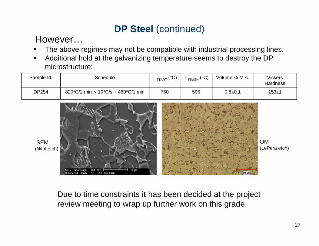
However…The above regimes may not be compatible with industrial processing lines.Additional hold at the galvanizing temperature seems to destroy the DP microstructure:
153±10.8±0.1506760820°C/2 min 10°C/s + 460°C/1 minDP254
Vickers Hardness
Volume % M.A.T FINISH (°C)T START (°C)ScheduleSample Id.
SEM(Nital etch)
OM(LePera etch)
27
DP Steel (continued)
Due to time constraints it has been decided at the project review meeting to wrap up further work on this grade
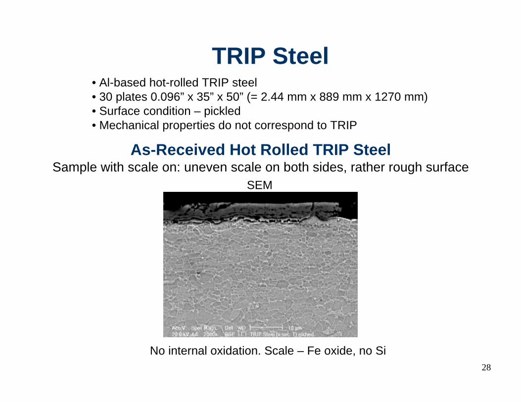
• Al-based hot-rolled TRIP steel• 30 plates 0.096” x 35” x 50” (= 2.44 mm x 889 mm x 1270 mm)• Surface condition – pickled• Mechanical properties do not correspond to TRIP
28
TRIP Steel
As-Received Hot Rolled TRIP SteelSample with scale on: uneven scale on both sides, rather rough surface
SEM
No internal oxidation. Scale – Fe oxide, no Si

Microstructure of As-Received Hot Rolled TRIP SteelOM – LePera etch
Microstructural banding; Ferrite + Bainite + very little MA
29
B
M-A
F
SEM
Volume fraction of retained austenite determined by XRD
= 1.7%

Microstructure of As-Received Hot Rolled TRIP SteelSEM – Inclusions
B
M-A
F
M-A
Inclusions:Elongated MnSAl2O3 attached to some MnS Al-N, TiC, …
30

31
Additional Heat Treatment of TRIP SteelDilatometer and Gleeble trials have determined reheating schedules producing desired microstructure with retained austenite
0
0.1
0.2
0.3
0.4
0.5
0.6
0.7
0.8
0.9
1
600 700 800 900 1000
Temperature (ºC)
Frac
tion
of γ
For
med
on
Hea
ting
TEST 1
TEST 2
Intercritical annealing at 850ºC produces about 50% austenite

TRIP Steel: Heat Treatment Thermal Profiles
050
100150200250300350400450500550600650700750800850900
0 20 40 60 80 100 120 140 160 180 200 220 240 260 280 300 320
Time (s)
Tem
pera
ture
( C)
050
100150200250300350400450500550600650700750800850900
0 20 40 60 80 100 120 140 160 180 200 220 240 260 280 300 320 340 360 380
Time (s)
Tem
pera
ture
( C
)
32
050
100150200250300350400450500550600650700750800850900
0 20 40 60 80 100 120 140 160 180 200 220 240 260 280 300 320 340 360 380 400
Time (s)
Tem
pera
ture
(ºC
)
HT1
HT2
HT3
Volume fraction of retainedaustenite determined by XRD:
12% (Gleeble sample)19% (Dilatometer sample)
11% (Gleeble sample)10-12% (Tube blancs)
13% (Dilatometer sample)

Examples of Microstructure of Heat-treated TRIP Steel
33
OM – LePera etch
HT1 HT3

Tensile Properties of TRIP Steel
34
0.20±0.0145±229±1634±1417±5Longitudinal
0.19±0.0149±130±1642±3453±8TransverseHT2850°C×1min +
460°C×1min
0.21±0.0147±231±1643±3407±4Longitudinal
0.20±0.0150±332±1646±4436±5TransverseHT1:850°C×2min +
460°C×1min
0.18±0.0165±436±3569±20398±18Longitudinal
0.16±0.0150±130±1595±1446±2TransverseAs-received(hot-rolled)
0.1527631478Unknown(longitudinal?)Supplier’s data
Strainhardening
n
Reductionof Area
(%)
TotalElongation
(%)
UltimateTensile Stress
(MPa)
Stress at0.2% Offset
(MPa)OrientationCondition

Remaining Experimental Work
Galvanize TRIP coupons (ongoing).Perform tensile tests on GI TRIP.Dynamic tests on GI TRIP.Hole expansion tests on GI TRIP.Fatigue tests on all the grades (ongoing).Tube welding and ring hoop tension tests on all the grades (ongoing).
35