Embed Size (px)
Citation preview
f funke funke means ndash fabrication utilities network know-how engineering
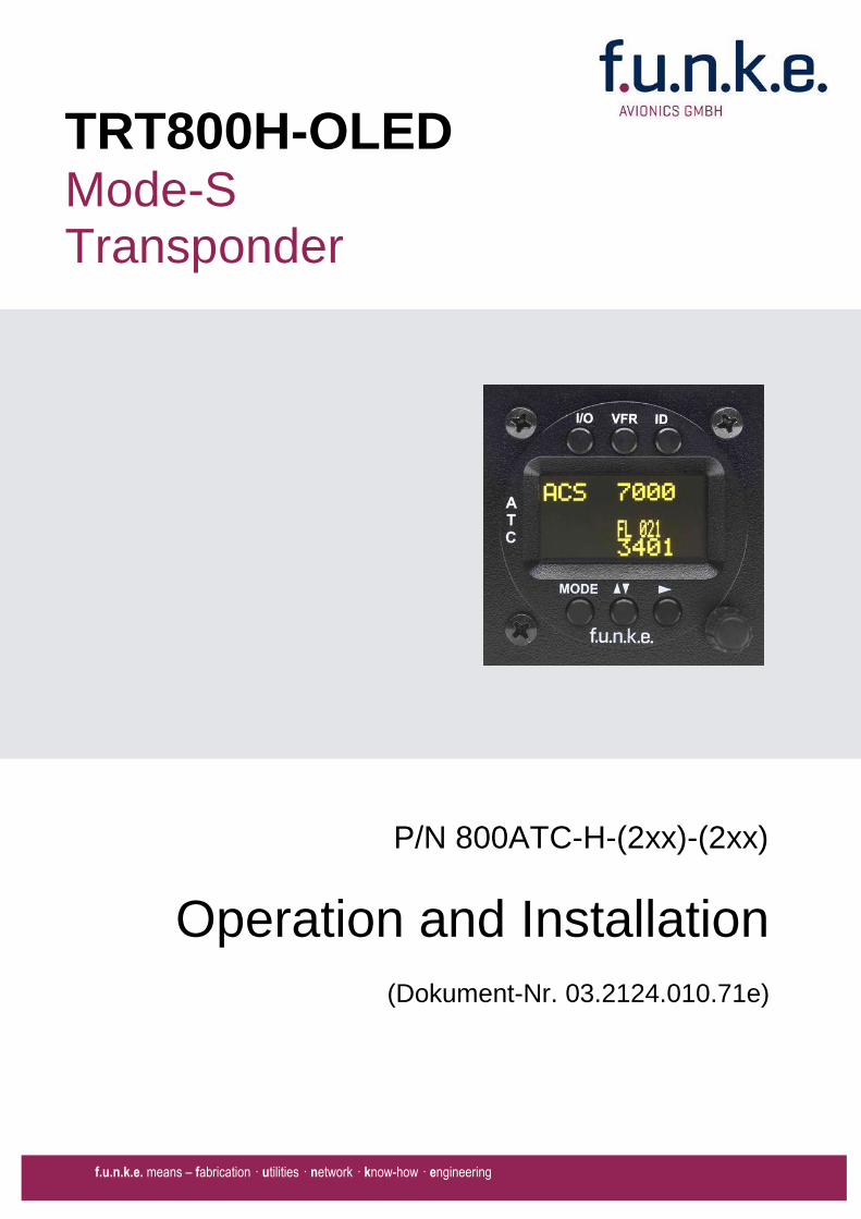
Operation and Installation
(Dokument-Nr 03212401071e)
PN 800ATC-H-(2xx)-(2xx)
TRT800H-OLED Mode-S Transponder
TRT800H PN 800ATC-H-(2xx)-(2xx)
Operation and Installation
2 Document-No 03212401071e Revision 210
Change History
Revision Date Description of Change
100 18112011 First Release
101 01112012 Extended functions remote control interface and altitude compensation starting from software version 53
102 23112012 Added information for TSO certification
103 22012013 Corrections
200 22012014 Change of company name to funke AVIONICS GmbH Inserted new EM800-cable plan in chapter373
210 15062015 Inserted new EM800-cable plan in chapter373
List of Service-Bulletins (SB)
Service Bulletins have to be inserted into this manual and to be enlisted in the following table
SB No Rev No Issue Date
Insertion Date Name
SB TRT800-A-H-1 104 17102008
Survey of Variants
Part Number Description
PN 800ATC-H-(201)ndash(210)
Version with OLED-Display one VFR-Code eight storable record sets for AA-AC-Code (ICAO 24bit-Address) FID Ground-Switch RI-Code GPS-Interface-Setting Auto-On-Function
PN 800ATC-H-(210)ndash(210)
Version with OLED-Display one VFR-Code eight storable record sets for AA-AC-Code (ICAO 24bit-Address) FID Ground-Switch RI-Code GPS-Interface-Setting Auto-On-Function remote control unit interface
TRT800H PN 800ATC-H-(2xx)-(2xx)
Operation and Installation
3 Document-No 03212401071e Revision 210
Table of Contents
1 GENERAL 5
11 Symbols 5
12 Abbreviations 6
13 Customer Support 6
14 Features 7
15 Deviations and Important Notes 8
2 OPERATION 9
21 Controls 9
22 Switch ONOFF 11
23 Display - Indications 12
24 Display-Brightness 13
25 Flight-ID (FID) 13
251 Display Flight-ID 13
252 Configure Flight-ID 14
26 Transponder Mode selection 14
27 Squawk-Setting 15
28 VFR ndash Squawk 15
29 ID ndash Special Position Identification (SPI) ldquoSquawk Identrdquo 16
210 Error-Codes 16
3 INSTALLATION 17
31 Notes 17
32 Telecommunication data 17
33 Scope of Delivery 17
34 Unpacking and Inspecting of the Equipment 18
35 Mounting 18
36 Equipment Connections 19
361 Electrical Connections 19
362 Static Air Port 20
37 Wiring 20
371 Conductor Cross Section 20
372 Pin Assignment 21
373 Cable plan External Memory EM800 22
TRT800H PN 800ATC-H-(2xx)-(2xx)
Operation and Installation
4 Document-No 03212401071e Revision 210
38 Antenna 25
381 Antenna Selection 25
382 Installation Recommendation 25
383 Antenna Wiring 25
39 Post-Installation Check 26
310 Starting Up 27
311 Accessories 27
312 Drawings 28
3121 Dimensions 28
3122 Mounting Advices 28
4 Transponder SETTINGS 29
41 Overview 29
42 Display Configuration Summary 29
43 General settings 31
431 ICAO 24-Bit Aircraft Address (AA) 31
432 Aircraft Category (AC) 31
433 Flight-ID (FID) 32
434 Reply Information - Speed Category (RI) 33
44 Optional settings 33
441 Option Ground-Switch 33
442 Option Remote Header 34
443 Serial Interface (RS232) 34
444 Altitude CorrectionOffset 35
45 Setup Procedure 36
451 Setup Menu Control 36
452 Transponder configurationrecord structure 37
453 Transponder configurationrecord handling 37
454 General Setup 37
455 Altitude Correction Setup 41
5 APPENDIX 43
51 Technical Data 43
52 Environmental Conditions 45
53 DO-178B Open Problem Reports 46
TRT800H PN 800ATC-H-(2xx)-(2xx)
Operation and Installation
5 Document-No 03212401071e Revision 210
1 GENERAL
This manual contains information about the physical mechanical and electrical characteristics and about installation and operation of the Mode S Transponder TRT800H
The conditions and tests required for TSO approval of this article are minimum performance standards Those installing this article either on or within a specific type or class of aircraft must determine that the aircraft installation conditions are within the TSO standards which include any accepted integrated non-TSO function standards TSO articles and any accepted integrated non-TSO function(s) must have separate approval for installation in an aircraft The article may be installed only according to 14 CFR part 43 or the applicable airworthiness requirements This is an incomplete system (antenna is required) intended to provide the TSO functions specified in this Operation and Installation Manual section 51
11 Symbols
Advices whose non-observance can cause radiation damage to the human body or ignition of combustible materials
Advices whose non-observance can cause damage to the device or other parts of the equipment
Supplementary information
TRT800H PN 800ATC-H-(2xx)-(2xx)
Operation and Installation
6 Document-No 03212401071e Revision 210
12 Abbreviations
Abb Meaning Explanation
FID Flight ID Flight plan number or if not assigned registration number of aircraft
SPI Special Position Identification
Activation on request by controllers bdquoSquawk Identldquo transmits SPI Pulse for 18 seconds which highlights the respective traffic item on the controllers radar screen
AA Aircraft Address assigned ICAO 24-bit address
AC Aircraft Category Defines aircraft type according to specific categories
RI Reply Information Maximum airspeed
13 Customer Support
In order to facilitate a rapid handling of return shipments please follow the instructions of the input guide bdquoReshipment RMAldquo provided at the Service-Area within the funke AVIONICS GmbH web portal wwwfunkeavionicsde
Any suggestions for improvement of our manuals are welcome Contact servicefunkeavionicsde
Information on software updates is available at funke AVIONICS GmbH
TRT800H PN 800ATC-H-(2xx)-(2xx)
Operation and Installation
7 Document-No 03212401071e Revision 210
14 Features
In order to operate the Mode S transponder it is necessary to request an ICAO 24-bit Aircraft Address at the responsible national aviation authorities The received Code is assigned to the specific transponderaircraft and must be configured within the transponder The 24-bit address is stored in an external memory which allows the transponder being exchanged without requiring any further configuration (for detailed information refer to sections 431 and 454)
Class 1 Level 2es non-diversity Mode S transponder for ground based interrogations at 1030 MHz and response at 1090 MHz
Replies to (Secondary) Radar Interrogations
o Mode A replies with a Squawk (one of 4096 possible Codes eg flight plan number Squawk assigned by a controller or the VFR Squawk 7000)
o Mode C replies including encoded flight level
o Mode S replies including aircraft address and flight level
o Extended Squitter containing additional information on position and velocity
IDENT capability for activating the Special Position Identificationldquo-Pulse (SPI) for 18 seconds which is requested by the Controller bdquoSquawk Identldquo
Maximum flight level 35 000 ft maximum airspeed 250 kt
Display information contains Squawk code mode of operation and pressure altitude
Temperature compensated high precision piezo-resistive pressure sensor
RS-232 IO data port enabling connection with certain GPS-Receivers in order to support ADS-B Out
8 storable entries for AA-AC-Code FID Ground-Switch RI-Code and GPS-Interface-setting (stored in external memory TRT800EMxx)
Remote control unit interface
TRT800H PN 800ATC-H-(2xx)-(2xx)
Operation and Installation
8 Document-No 03212401071e Revision 210
15 Deviations and Important Notes
The following deviations have been granted by the FAA
The device is certified to FAA TSO-C112c in lieu of FAA TSO-C112d
Environmental Qualification Testing was performed according to RTCADO-160D in lieu of RTCADO-160F
The Software of this device was developed according to RTCA DO-178B Design Assurance Level D
The ADS-B function of this device has not been evaluated during the FAA TSO certification process other than to ensure non-interference Due to the SW assurance of DAL D the ADS-B function cannot be used in the US National Airspace
Connecting a GPS source will not comply to FAA certification requirements with regard to ADS-B
This device contains an altitude measuring device that has not been evaluated during the FAA TSO certification process other than to ensure non-interference
This feature must be evaluated for intended function during FAA installation approval
Compliance to RTCA DO-181D was verified by testing against EUROCAE ED-73C The two standards are technically identical with regard to the TRT800H
TRT800H PN 800ATC-H-(2xx)-(2xx)
Operation and Installation
9 Document-No 03212401071e Revision 210
2 OPERATION
21 Controls
ON OFF
bdquoSquawk Identldquo
Activate deactivate VFR
Change Active Standby
Squawk
Select Operation Mode
Cursor adjustment
Rotary Knob for adjusting values at the cursor position
active
Operation
Mode
standby Standby Squawk
Active Squawk
TRT800H PN 800ATC-H-(2xx)-(2xx)
Operation and Installation
10 Document-No 03212401071e Revision 210
IO ONOFF
Switch ON press button for approx 05 s
Switch OFFpress button for approx 3 s
VFR VFR
activatedeactivate VFR Squawk (press shortly)
store active Squawk as VFRVFRW-Squawk (press button 3 s rarr28)
CHANGE
change between active and standby-Squawk
works as cursor back button (opposite function of the cursor button) during entering values and also for navigating backwards through the configuration menu (rarr454)
ID IDENT
bdquoSquawk Identldquo sends Ident marking (SPI) for 18 s (rarr 29)
Enter Flight-ID (FID) setup (in standby mode press button for approx 5s)
MODE MODE Select transponder operational mode (rarr 26)
CURSOR Set position of Cursor
Rotary Knob
AdjustEnter values at current cursor position select options set standby Squawk (rarr 27)
TRT800H PN 800ATC-H-(2xx)-(2xx)
Operation and Installation
11 Document-No 03212401071e Revision 210
22 Switch ONOFF
Switch ON press IO for 05 s
Switch OFF press IO for 3 s
221 Display information after power up
After turning-on the display appears as follows (example)
If more than one configuration record is programmed the record selection menu appears (example)
Select the desired record (rotary switch) and confirm with MODE
If no external memory is connected or no 24bit address is defined the message ldquoCRADLE OFFrdquo appears In this case the device is working as ldquoMode AC onlyrdquo transponder
The transponder starts in STBY mode
2000 FL 030
STBY 7000
Cradle OFF
24D5F2 lt 000000 BE2343 000000 D4B3AA 000000 000000 000000
TRT800H V53
FPGA-Vers 102
Device Name
Software Version
Firmware Version
TRT800H PN 800ATC-H-(2xx)-(2xx)
Operation and Installation
12 Document-No 03212401071e Revision 210
23 Display - Indications
Value Meaning Remarks
7000 active Squawk
2000 Standby Squawk Could be changed with active Squawk by pressing
FL 030
FLerr
Flight Level
Invalid altitude measuring
Flight Level (in 100 ft steps)
Beyond -1000 35 000 ft C Mode gets inactive
ACS Operational Mode (STBY A-S ACS AC A)
Modes see section 26
IDT transmits Ident-Marking (SPI) ID (bdquoSquawk Identldquo) has been pressed ndash active for 18 s
Transponder replies
on Mode-S Mode-A or Mode-C interrogations
No indication on ADSB and squitter transmission
| Transponder is locked by a ground station and will be directly addressed
Lock Information (indicated below the diamond)
F
G
in-flight
on-ground
Ground-Switch-Info
(if installedavailable)
ACS
7000
TM
PLLTRX DC | BATDIM
IDT FL 030
STBY 2000 F
Passive Squawk
Active Squawk
Test mode indicatior
GND switch status
Operational Mode Standby
SPI indicator
Error indications
Reply indication
Lock out indication
Flight level
Backlight setup
Low battery ind
Operational Mode Active
TRT800H PN 800ATC-H-(2xx)-(2xx)
Operation and Installation
13 Document-No 03212401071e Revision 210
Value Meaning Remarks
Error indicators
PLL PLL Error Internal Error
TRX Transmit Failure Check antenna and wiring
DC Low internal voltage Internal error
FPG FPGA-Failure Internal error
BAT Battery Power too low maybe batterygenerator fault
24 Display-Brightness
In active mode (not standby) press for 2 s
Display indicates ldquoDIMrdquo Adjust brightness (DIM) with rotary knob
Return to normal operation press or wait 5 s
25 Flight-ID (FID)
The FID is an identifier required for Mode S Operation During future application of flight plans a FID could be assigned on a per flight basis If no FID is assigned (todayrsquos normal case) the registration marking of the aircraft should be used as FID The FID should not contain dashes or blanks The FID must not be confused with the 24-bit Aircraft Address
251 Display Flight-ID
Press MODE (repeatedly) until bdquoSTBYldquo appears
Press and hold ID while a counter is shown beside the active squawk During a few seconds Flight Identification is displayed
FID 02
A B C D E F G H
-
TRT800H PN 800ATC-H-(2xx)-(2xx)
Operation and Installation
14 Document-No 03212401071e Revision 210
252 Configure Flight-ID
Press MODE (repeatedly) until bdquoSTBYldquo appears
Press and hold ID while a counter is shown beside the active squawk Release ID when ldquoCHANGE FIDrdquo is displayed
Enter Flight-Id with cursor button and rotary knob
Press MODE to save and return to STBY
Please refer to section 454 for configuration of the 24-bit Address (AA) and Aircraft Category (AC)
26 Transponder Mode selection
Press MODE (repeatedly) to select from following Modes
STBY bdquoStandbyldquo Transponder does not respond to any interrogation Squitter and ADS-B output is not active
A C S bdquoMode A+C+Sldquo Standard condition transponder responds to mode A C and S interrogations
A ndash S bdquoMode A+S no Cldquo Altitude is not transmitted (neither on C nor on S requests) All other Mode-S data as well as Mode-A replies are transmitted
Enter FID left-aligned without any blanks or dashes () eg 12345621DEFAV for the marking D-EFAV The last remaining digits shall be filled with blanks
CHANGE FID
_ _ _ _ _ _ _ _ A B C D E F G H
- exit
TRT800H PN 800ATC-H-(2xx)-(2xx)
Operation and Installation
15 Document-No 03212401071e Revision 210
If no 24-bit address (AA) was defined or entered as ldquo000000ldquo the transponder operates as a Mode AC transponder in that case the following Modes are possible apart from Standby
A C ndash bdquoMode A+Cldquo Transponder replies only on Mode A and Mode-C interrogations
A ndash ndash bdquoMode Aldquo Transponder replies only on Mode A interrogations
In STBY (Standby) mode all transponder transmissions are disabled completely Therefore the transponder is not visible in this mode to air traffic control or the anti-collision systems onboard other aircrafts
Never use the STBY mode in flight unless you are requested to do so by air traffic control Always remember to put the transponder in active mode prior to take off
27 Squawk-Setting
The active Squawk is displayed in the upper line while the standby Squawk is presented at the lower line
Setting the Standby Squawk
Press to set the cursor (bdquo^ldquo) turn rotary knob to set numbers of the standby Squawk
Press to activate the Standby Squawk (this moves the current active Squawk into Standby)
28 VFR ndash Squawk
The transponder features a user-defined squawk code for VFR-flight (factory setting 7000)
Activate VFR-Squawk
Press VFR (bdquoVFRldquo is indicated) now the active Squawk is moved into Standby but not visible because the indication of the Standby Squawk is overlapped by bdquoVFRldquo
TRT800H PN 800ATC-H-(2xx)-(2xx)
Operation and Installation
16 Document-No 03212401071e Revision 210
Display Standby Squawk
Press VFR or or use the rotary knob (the VFR-Squawk remains active)
Example
VFR VFR
Now the Standby Squawk can be adjusted by using the rotary knob and activated with
In order to store the current active Squawk as new VFR-Squawk (replacing the factory setting 7000) Press and hold VFR until an bdquoSldquo is indicated (approx 3 s) after releasing the button bdquoVFRldquo is shown
29 ID ndash Special Position Identification (SPI) ldquoSquawk Identrdquo
Press ID to activate transmission of the special position identification pulse with every reply within 18 seconds ldquoIDTrdquo appears on the display
By pressing ID a special position identification pulse (SPI) is transmitted with every reply within 18 seconds which causes an accented marking on the Controllerrsquos screen The bdquoSpecial Position Identificationldquo has to be activated after the bdquoSquawk Identldquo request of the Controller
210 Error-Codes
Please refer to 23 Display - Indications for possible displayed errors
7000
FL 030
STBY 4700
7000
FL 030
STBY VFR
4700
FL 030
STBY 5600
TRT800H PN 800ATC-H-(2xx)-(2xx)
Operation and Installation
17 Document-No 03212401071e Revision 210
3 INSTALLATION
31 Notes
The following suggestions should be considered before installing
The assigned installation company will supply wiring For diagrams refer to 37 Wiring
Transponder External Memory all cables and antennas shall be installed according to bdquoFAA AC-14313-2A Acceptable Methods Techniques and Practices ndash Aircraft Alterationsldquo and the appropriate manufacturerrsquos instructions
32 Telecommunication data
Depending on your national telecommunications legislation the following data may be required when applying for the aircraft radio station license
Manufacturer funke AVIONICS GmbH
Type Designation TRT800H
EASA Number EASA21O269
Transmitter Power Output
126 W
Frequency 1090 MHz
Emission Designator 12M0M1D
33 Scope of Delivery
Item namenumber Description
TRT800H Transponder TRT800H
TRT800EMSS External Memory (Aircraft-Address-Adaptor with wiring)
M4X8ZSW (3 pieces) screw for panels up to 5 mm thickness
56S101A4 TNC antenna connector
03212401071e Manual bdquoOperation and Installationldquo
EASA Form 1
TRT800H PN 800ATC-H-(2xx)-(2xx)
Operation and Installation
18 Document-No 03212401071e Revision 210
34 Unpacking and Inspecting of the Equipment
Carefully unpack the equipment and inspect for transport damages If a damage claim has to be filed save the shipping container and all packing materials as evidence to your claim
35 Mounting
In cooperation with a maintenance shop location and kind of the installation are specified The maintenance shop can supply all cables Suitable sets of cables are available from funke AVIONICS GmbH
Select a position away from heat sources Provide space for adequate convection cooling
Leave sufficient space for the installation of cables and connectors
Avoid sharp bends and wiring close to control cables
Leave sufficient lead length for inspection or repair of the wiring of the connector (containing the memory) so that when the mounting hardware for the rear connectors is removed the assembly may be pulled forward several inches
Bend the harness at the rear connectors to inhibit water droplets (formed due to condensation) from collecting in the connector
For mounting detailsdrawing refer to chapter 3122 Mounting Advices
For storage or reshipment the original packaging should be used
TRT800H PN 800ATC-H-(2xx)-(2xx)
Operation and Installation
19 Document-No 03212401071e Revision 210
36 Equipment Connections
361 Electrical Connections
One 15 pin D-SUB miniature connector includes all electrical connections except for the antenna Use only an External Memory Adapter TRT800EMxx as this is part of the certification and includes a memory device in which the ICAO 24-bit Aircraft Address is stored
3611 Mutual Suppression
Other equipment on board (e g DME) may transmit in the same frequency band as the transponder
If such a device is installed a suppression wiring shall be installed in order to protect the receiving parts of the different devices from in-band transmissions
Mutual suppression is a synchronous pulse that is sent to the other equipment to suppress transmission of a competing transmitter for the duration of the pulse train transmission The transponder transmission may be suppressed by an external source and vice versa
To activate mutual suppression connect the SUPP_IO signal to the according signals of the other equipment
3612 Ground Switch
If an external Ground-Switch is connected to the transponder and activated in the setup the transponder can detect if the aircraft is airborne or on the ground This allows the transponder to automatically activate the Ground mode whenever the aircraft is on ground
In order to activate this feature the input bdquoFLY-GNDldquo must be connected to an external switch which connects the input pin with bdquoGNDldquo when the gear is weighted or remains open in the other case
This feature must additionally be activated in the Setup For details on configuration please refer to section 454
The (+UB)-wire has to protected by circuit breaker (2 Amp)
TRT800H PN 800ATC-H-(2xx)-(2xx)
Operation and Installation
20 Document-No 03212401071e Revision 210
3613 Auto-On
The Auto-On input allows to define how the transponder will behave when power is supplied to it
If the aircraft is equipped with a dedicated avionics master switch that switches the power supply to the transponder the pin Auto-On must be wired together with the UB+ pin to the avionic master switch The onoff button on the transponder is without function in that case The transponder will start automatically whenever power is supplied
On aircraft without such an avionics master switch the pin Auto-On must be left unconnected In this case the transponder must be switched on and off via the transponders onoff button on the front panel
362 Static Air Port
Install a silicon soft tube fitting the 5 mm static air hose at the backside of the transponder and secure plumbing with appropriate clamps
37 Wiring
371 Conductor Cross Section
Power Supply (Power GND) AWG20 (062 mmsup2)
Signals AWG22 (038 mmsup2)
The conductors must be approved for aircraft use
TRT800H PN 800ATC-H-(2xx)-(2xx)
Operation and Installation
21 Document-No 03212401071e Revision 210
372 Pin Assignment
The transponder may only be operated together with an external memory address adaptor TRT800EMxx
Pin Signal Remarks Adaptor
Typ(4)
TRT800
EM
Adaptor
Typ(4)
TRT800
EMSS
Adaptor Typ
TRT800
EMRS
1 GND -
2 Remote control(1) Input
3 EEPROM Signal TRT800EMxx internal
4 EEPROM Signal TRT800EMxx internal
5 TX RS-232 Serial Output
6 Switched +UB(1) Output
7 Remote control(1) Output
8 +UB power supply Input
9 GND -
10 EEPROM VCC TRT800EMxx internal
11 EEPROM GND TRT800EMxx internal
12 RX RS-232 Serial Input
13 Suppression Input Output
14 Auto-On(2) Input(2)
15 Fly-GND Switch(3) Input(3)
= in the plug and get out = in the plug and not get out ∕ = internal connection to the device
(1) SWITCHED +UB OUT Interface Remote control
May only be used for compatible funke AVIONICS devices Do not connect pins if interface is not used
(2) Auto-On Connect to +UB override front panel onoff button Leave unconnected to use front panel onoff button
(3) Ground Switch
FLY-GND
If an external Ground Switch is connected it must connect this pin to GND to indicate the on-ground condition Leave open otherwise
(4) Adaptors TRT800EM amp TRT800EMSS
Adaptor version does not provide full interface capability (see table for details)
TRT800H PN 800ATC-H-(2xx)-(2xx)
Operation and Installation
22 Document-No 03212401071e Revision 210
373 Cable plan External Memory EM800
3731 Cable plan TRT800EMRS (older version with interface remote)
to SN 90932013
DSUB 15pol
TRT800HTRT800A
lt PIN-5 gt
lt PIN-12gt
lt PIN-15gt
lt PIN-13gt
lt PIN-7 gt
lt PIN-2 gt
lt PIN-6 gt
lt PIN-1 gt
lt PIN-9 gt
lt PIN-8 gt
lt PIN-14gt
TXD
RXD
FLY_GND
SUPP_IO
GND
open
cable
ends
Remote Binder
Connector
female
white
black
yellow
red
shield
blue
red
brown
GND
+UB
AUTO-ON(2)(3)
black
white
red
yellow
shield
Binder Connector female
(solder side)
1 2 3 4 5 6 7 8
9 10 11 12 13 14 15
D-SUB Connector female
(solder side)
open
cable
ends
1 New interface available
-at TRT800H starting from SN 30430109 with SW V53
-at TRT800A starting with SW V53 2 New TRT800H interface starting from HW 60 3 port function not available at TRT800A
3
4 2
5 1
RMT-LIGHT
GND
RMT-TXD
RMT-SW+UB
RMT-RXD
RMT-TXD(1)
RMT-RXD(1)
RMT-SW+UB(2)(3)
RMT-LIGHT(2)
GND(1)
TRT800H PN 800ATC-H-(2xx)-(2xx)
Operation and Installation
23 Document-No 03212401071e Revision 210
3732 Cable plan TRT800EMRS (newer version with interface remote)
from SN 90932114
DSUB 15pol
TRT800HTRT800A
lt PIN-5 gt
lt PIN-12gt
lt PIN-15gt
lt PIN-13gt
lt PIN-7 gt
lt PIN-2 gt
lt PIN-6 gt
lt PIN-1 gt
lt PIN-9 gt
lt PIN-8 gt
lt PIN-14gt
TXD
RXD
FLY_GND
SUPP_IO
GND
open
cable
ends
Remote Binder
Connector
female
white
brown
yellow
green
shield
blue
red
brown
GND
+UB
AUTO-ON(2)(3)
brown
white
green
yellow
shield
Binder Connector female
(solder side)
1 2 3 4 5 6 7 8
9 10 11 12 13 14 15
D-SUB Connector female
(solder side)
open
cable
ends
1 New interface available
-at TRT800H starting from SN 30430109 with SW V53
-at TRT800A starting with SW V53 2 New TRT800H interface starting from HW 60 3 port function not available at TRT800A
3
4 2
5 1
RMT-LIGHT
GND
RMT-TXD
RMT-SW+UB
RMT-RXD
RMT-TXD(1)
RMT-RXD(1)
RMT-SW+UB(2)(3)
RMT-LIGHT(2)
GND(1)
TRT800H PN 800ATC-H-(2xx)-(2xx)
Operation and Installation
24 Document-No 03212401071e Revision 210
3733 Cable plan TRT800EMSS (newer version without interface remote)
from SN 91032115
The External ndash Memory ndash Address - Adapter TRT800EMxx contains electronic parts and must not be opened Opening or modifying the connector leads to the loss of airworthiness certification
DSUB 15pol
TRT800HTRT800A
lt PIN-5 gt
lt PIN-12gt
lt PIN-15gt
lt PIN-13gt
lt PIN-1 gt
lt PIN-9 gt
lt PIN-8 gt
lt PIN-14gt
TXD
RXD
FLY_GND
SUPP_IO
GND
open
cable
ends
white
brown
yellow
green
shield
blue
red
brown
GND
+UB
AUTO-ON(2)(3)
open
cable
ends
2 New TRT800H interface starting from HW 60 3 port function not available at TRT800A
1 2 3 4 5 6 7 8
9 10 11 12 13 14 15
D-SUB Connector female
(solder side)
TRT800H PN 800ATC-H-(2xx)-(2xx)
Operation and Installation
25 Document-No 03212401071e Revision 210
38 Antenna
381 Antenna Selection
Recommended antennas see section 311 Accessories
Choose an antenna type compatible with the vehicle and the mounting location
Specified features depend on proper installation of the antenna
The radiation pattern needs to be verified considering aircraft type and mounting location
The electrical interference between the antenna and any other equipment must be taken into account in such a way that no reduction of the performance of any other system will occur
Install only certified antennas
382 Installation Recommendation
Take note of the antenna manufacturerrsquos instructions
The usually deployed Dipole- or Blade antennas necessarily require a high frequency capable solid metal ground plane at the antenna base
For installation in composite aircrafts ground planes are to be added The ground plane should be as large as possible but in any case not smaller than 10 cm x 10 cm If in doubt please contact the aircraft manufacturer
Keep away three feet from any other antenna
Pursue mounting in vertical position under the belly in flight direction
383 Antenna Wiring
Suitable antenna cables see section 311 Accessories
Keep wiring as short as possible
The smallest cable bend radius is 10cm Avoid sharp bends
Keep away from an ADF antenna cable at least 12 inches
Electrical connections to the antenna shall be protected against moisture to avoid loss of efficiency
TRT800H PN 800ATC-H-(2xx)-(2xx)
Operation and Installation
26 Document-No 03212401071e Revision 210
39 Post-Installation Check
All steering and control functions of the aircraft are to be examined in order to exclude disturbances by the wiring
The most important factor in the transponder configuration is the setting of the ICAO address (see section 454)
Attenuation from antenna to transponder at 1090 MHz must not exceed 15 dB
A certified maintenance shop must verify proper operation of the transponder by testing in accordance with Appendix F of ldquo14 CFR Part 43 ndash ATC Transponder Tests and Inspectionsrdquo
TRT800H PN 800ATC-H-(2xx)-(2xx)
Operation and Installation
27 Document-No 03212401071e Revision 210
310 Starting Up
Turn the transponder on with IO After start-up the following screens appear
311 Accessories
Part Number Description
TRKABEL1 Antenna cable 10 m (32 ft) TNC BNC
TRKABEL2 Antenna cable 25 m (82 ft) TNC BNC
TRKABEL3 Antenna cable 40 m (132 ft) TNC BNC
TRKABEL4 Antenna cable 65 m (213 ft) TNC BNC
TRT800EMRS External-Memory (Aircraft-Address-Adaptor) Connection cable with interface TRT-Remote control
CI-105 TransponderDME Antenna TSO C66b C74c
CI105 Comant Industries Inc
Height 325rdquo Weight 90 g (02 lbs)
AV22 Transponder Rod antenna TSO C74c
AV-22 R A Miller Industries
The TRT800H starts in standby mode (indicated with STBY) In order to change into operational mode (indicated with ACS) press MODE If ground switch is connected and status ldquoin flightrdquo is selected TRT800H starts in active mode
Very important is the correct configuration of the 24bit Aircraft-Address (see 454 General Setup)
TRT800H V53
FPGA-Vers 102
2000 FL 030
STBY 7000
TRT800H PN 800ATC-H-(2xx)-(2xx)
Operation and Installation
28 Document-No 03212401071e Revision 210
312 Drawings
3121 Dimensions
20mm15 mm
170 mm
TRT800TRT800H
65 mm
65
mm
Oslash 57 mm
Static Air
Antenna
PowerRS232
3122 Mounting Advices
Connections Area
8
0 m
m
Panel Cut-out
470 mm
470
mm
575 mm
4 x Oslash 4 mm
Oslash
Connector (plug) has to be clamped with both spring locks
No screws may be turned in more than max 15mm into the device ndash even if no hard limit is noticeable
Fixing clips (spring) left right
TRT800H PN 800ATC-H-(2xx)-(2xx)
Operation and Installation
29 Document-No 03212401071e Revision 210
4 TRANSPONDER SETTINGS
41 Overview
The TRT800H is capable of storing the following information
ICAO 24-Bit Aircraft-Address (AA)
Aircraft Category (AC)
Flight Identification (FID)
Ground-Switch (YesNo)
Speed Category (RI)
RS232 Interface Configuration
All of these data are configurable in the Setup and are stored in the external memory module integrated within the housing of the D-Sub connector (included in the delivery)
The cable with this connector shall remain in the aircraft even if the unit is removed to ensure that the ICAO 24bit aircraft address is fixed to the aircraft
Additionally the following usertransponder related settings are stored transponder internally
Active Squawk
Passive Squawk
VFR Squawk
Altitude offset
Display brightness
42 Display Configuration Summary
Transponder provides the opportunity to show summary of complete current settings To access configuration summary pages push and hold
ID in Standby mode Release ID if ldquoSHOW SETUPrdquo is displayed The summary is subdivided into the following pages
TRT800H PN 800ATC-H-(2xx)-(2xx)
Operation and Installation
30 Document-No 03212401071e Revision 210
Page 1
Aircraft Address
Aircraft Category
Flight Identification
MODE
Page 2 Speed Category
Ground Switch option
Remote Header option
MODE
Page 3 RS-232 Settings
Protocol baud rate position (if available)1
MODE
Page 4 Altitude correction settings
(part 1)
MODE
Page 5 Altitude correction settings
(part 2)
Note 1 Position data will only be displayed if
a GPS protocol is set as interface protocol (NMEA FREEFLIGHT AR-NAV)
18000 ft 0ft 25000 ft + 100ft 35000 ft - 50ft
exit
ALTITUDE CORRECTION 2000 ft 0ft 10000 ft + 100ft next
RS-232 NMEA Baud 4800 Pos 481 99 next
Speed Cat 8 Ground Sw YES Remote Hd NO next
AA F E 1 2 3 4 AC 1 9 FID 4 4 E 1 2 3 next
TRT800H PN 800ATC-H-(2xx)-(2xx)
Operation and Installation
31 Document-No 03212401071e Revision 210
GPS receiver is connected and transmits data (if not ldquoPos no datardquo is displayed)
a valid position is transmitted (if not ldquoPos wrong datardquo is displayed)
While configuration summary page is displayed no new position data will be processed
43 General settings
431 ICAO 24-Bit Aircraft Address (AA)
Ask your national aviation authority (e g in Germany LBA Referat B5 Department ldquoVerkehrszulassungrdquo) how to obtain the AA In the case of aerial sports equipment the contact point would be the respective associations Only the assigned AA has to be used and must not be modified at any time because a duplicate address would jeopardize the data surveillance and integrity figures of Mode S
If no AA is stored after power on the display shows ldquoCRADLE OFFrdquo and the transponder operates in Mode AC
(Configuration of the AA see section 454)
432 Aircraft Category (AC)
Code Description Code Description
11 Emergency Vehicle 1C Ultra-Light Paraglider
12 Service Vehicle 1E Drone
19 Glider 21 Aircraft (D-Exxx) lt 15500 lbs Motor Glider (D-Kxxx)
1A Balloon amp Airship 22 Aircraft ge 15500 lbslt 75000 lbs
1B Paratrooper 27 Rotorcraft
Only one of the Codes mentioned in the table above must be used
Setuprarr454
Setuprarr454
TRT800H PN 800ATC-H-(2xx)-(2xx)
Operation and Installation
32 Document-No 03212401071e Revision 210
433 Flight-ID (FID)
Per ICAO regulation Mode-S data must contain a valid flight identification (FID) to ensure that the correlation between flight plan and radar data will work automatically
FID setting is required to correspond to the aircraft identification that has been specified at item 7 of the ICAO flight plan It contains seven characters at a maximum (left-aligned no additional zeros dashes or spacesblanks)
For an aircraft using a company call sign the Flight-ID mostly consists of the ICAO three-letter designator for the aircraft operator followed by an identification code eg KLM511 BAW213 JTR25
If no company call sign is used or no flight plan is filed the default FID to be set consists of the registration marking of the aircraft (eg DEABC) with no dashes spacesblanks or additional zeros even if they are included in the registration marking on the aircraft (tail number) While entering the FID into the transponder the last remaining digits must be filled with blanks
The ICAO Flight Plan only specifies 7 characters for FID funke AVIONICS reserves 8 characters as stated in ED-73B for further expansion of the flight plan
The user shall only program 7 characters for FID
Setuprarr454
TRT800H PN 800ATC-H-(2xx)-(2xx)
Operation and Installation
33 Document-No 03212401071e Revision 210
434 Reply Information - Speed Category (RI)
Besides AA AC and FID another important part of the Mode-S data is the Speed Category of the respective aircraft This speed category shall be configured in the setup and must contain one of the following codes
Code Description
08 No maximum airspeed data available
09 Maximum airspeed le 75 kt
10 75 kt gt maximum airspeed le 150 kt
11 150 kt gt maximum airspeed le 300 kt
12 300 kt gt maximum airspeed le 600 kt
13 600 kt gt maximum airspeed le 1200 kt
14 Maximum airspeed gt 1200 kt
15 Not assigned
44 Optional settings
441 Option Ground-Switch
If a ground switch is connected (and enabled in setup) the transponder is able to determine on-ground and in-flight state On-ground state is activated automatically once the gear touches the ground On-ground state is indicated on display by symbol G (apart from lsquoFrsquo for In-flight-state)
In On-ground-state the transponder will reply differently to certain addressed interrogations Also the transmission rate of some periodically sent data (squitters ADS-B) is reduced This allows ATC to distinguish between airborne aircraft and those on the ground and it reduces the Mode S channel load
For small aircraft authorities normally do not require such a ground switch In this case the transponder will use the same data formats on the ground as in the airborne state
Setuprarr454 Wiringrarr373
Setuprarr454
TRT800H PN 800ATC-H-(2xx)-(2xx)
Operation and Installation
34 Document-No 03212401071e Revision 210
442 Option Remote Header
The transponder provides a TRT800RT remote control interface If a remote header TRT800RT is connected transponder can be remote controlled via this interface Remote interface provides control of all standard user inputs available during standard operational mode For more information see TRT800RT manual Remote control interface de-activation is setup configurable Remote control interface must only be connected to TRT800RT
443 Serial Interface (RS232)
Using serial interface a GPS receiver can be connected to broadcast own position via ADS-B Out position message Position could be received by other appropriately equipped aircrafts and processed for collision avoidance ADS-B Out functionality
The ADS-B function of this device has not been evaluated during the FAA TSO certification process other than to ensure non-interference Due to the SW assurance of DAL D the ADS-B function cannot be used in the US National Airspace Connecting a GPS source will not comply to FAA certification requirements with regard to ADS-B
Supported formatsprotocols are
Option Description Baud rate
FREEFLIGHT GPSWAAS Sensor 1201
NexNav NNL 3101
19200
AR-NAV Bendix King
KLN 89B KLN 94 ldquoStandard RS232 Sentencerdquo
KMD 150 ldquoSentence Type 1rdquo
Garmin 400 Series ldquoSentence Type 1rdquo (with and without altitude data)
9600
NMEA NMEA-Format data format RMC is expected
4800
Setuprarr454 Wiringrarr373
Setuprarr454 Wiringrarr373
TRT800H PN 800ATC-H-(2xx)-(2xx)
Operation and Installation
35 Document-No 03212401071e Revision 210
Option Description Baud rate
FAVISIA Glass Cockpit support
FAVISIA Data format to be processed in FAVISIA avionics suite
-
FAVISIA+GPS Data format to be processed in FAVISIA avionics suite (output) and additional processing of incoming NMEA GPS-Receiver position data to support the ADS-B Out functionality
4800
Other
Comm-AB-support
Data format for special purpose An additional data link processor allows COMM-AB operation and processing of the position information of a flight management system simultaneously
38400
Disabled No communication via RS232 interface -
444 Altitude CorrectionOffset
The TRT800H has an integrated temperature compensated high-precision pressure sensor This sensor is factory-calibrated so that it will yield accurate flight level (uncorrected pressure altitude) within the entire altitude range
However due to differences in calibration of the TRT800H pressure sensor and the altimeter in the cockpit it may become necessary to adjust the TRT800H pressure readings so that the value indicated and transmitted by the TRT800H corresponds to the indication of the primary altimeter seen by the pilot within 125 feet (as specified in ETSO C88aSAE AS 8003)
Setting for all described GPS-systems
1 2 position messages per 2 sec
Setuprarr455
TRT800H PN 800ATC-H-(2xx)-(2xx)
Operation and Installation
36 Document-No 03212401071e Revision 210
The check for correspondence between the primary altimeter and the TRT800H is usually performed every 24 months as part of the aircrafts altimeter checks
Altitude correction is based on setup configurable offset values at five interpolation points ( 2000 8000 18000 25000 and 35000 ft)The offset value itself is limited to a range from -100 to + 100ft at each point (10ft steps)
45 Setup Procedure
Programming of the ICAOA 24-bit Aircraft Address and of the Aircraft Category shall be executed by qualified personnel only
A wrong Aircraft Address or Flight ID may cause serious problems ATC or with ACASTCAS systems
Pilot and owner are responsible for correctly set transponder data
451 Setup Menu Control
In order to access the functions described in the following paragraphs push and hold ID in Standby mode Release ID if desired counter value menu name is displayed to enter the menu The following menu entries are selectable
Count Displayed Name Function
03 FID FID is displayed
48 CHANGE FID Enter FID setup page
913 SHOW SETUP Enter setup summary listed on different pages (no changes possible)
2528 ENTER SETUP Enter transponder general configuration pages
3134 ALTITUDE CORRECTION
Enter altitude correction menu
TRT800H PN 800ATC-H-(2xx)-(2xx)
Operation and Installation
37 Document-No 03212401071e Revision 210
452 Transponder configurationrecord structure
Aircraft related parts of transponder configuration are stored in one out of eight possible records (record=presetting) Each record contains the following information
Aircraft Address (AA 24bit)
Aircraft category (AC)
Flight identification (FID 6-8 numbersletters)
RS-232 Interface setting (eg GPS protocol)
Ground-Switch setting (Installed YesNo)
Speed category (RI) of the respective aircraft
Remote Header setting (Installed YesNo)
User related settings (eg squawk codes display brightness) are stored once in one global record (transponder internally)
453 Transponder configurationrecord handling
At least one record is stored in external memory Up to 8 records can be additional be applied during setup process
If more than one record is applied the active record must be selected out of a list (determined by FID) during start-up of the transponder
Previously applied records can be deleted again by filling FID with zerorsquos only
454 General Setup
Any menu item can be passed by MODE If no changes are made the original settings will remain stored Modification of one menu item does not impact the others No entries will be deleted
TRT800H PN 800ATC-H-(2xx)-(2xx)
Operation and Installation
38 Document-No 03212401071e Revision 210
Step Display (Example)
1 Start-up Transponder
2 Ensure the transponder-mode is bdquoSTBYldquo If necessary change the mode by pressing MODE
3 Press ID A counter is shown at the upper-right corner Hold ID till ldquoENTER SETUPrdquo is displayed
4 After release of ID the first setup menu is displayed
5 helliphellipselect position (^)
rotary knobchange value
MODE
6 With the rotary knob you can select bdquoyesldquo if a Ground Switch is installed if not select ldquonordquo and proceed with step 7
MODE
Record 1
GND Switch YesNo
next
AA EF123456
AC 18
FID ^BCDEFG
next
AA EF123456
AC 18
FID ABCDEFG
next
ENTER SETUP 26
2000 FL 030
STBY 7000
TRT800H PN 800ATC-H-(2xx)-(2xx)
Operation and Installation
39 Document-No 03212401071e Revision 210
Step Display (Example)
7 At this stage the respective speed category shall be selected by using the rotary knob
MODE
8 At this stage a GPS receiver for ADS-B Out can be selected (Selectable by rotary knob)
MODE
9 At this stage remote interface for communication between TRT800H and remote header can be activated (Selectable by rotary knob)
Remote interface must only be activated if a remote header is connected
MODE
10 With ID further Records can now be created and configured as described in the aforementioned steps At start-up of the transponder one of the defined records with all associated configurations need to be selected
MODE
Records ID=Edit Records
EXIT
Record 1
REMOTE Header YesNo
next
Record 1
GPSINTEXT NMEA
next
Record 1
Speed Cat 08-15
next
TRT800H PN 800ATC-H-(2xx)-(2xx)
Operation and Installation
40 Document-No 03212401071e Revision 210
Step Display (Example)
11 You have now left the configuration mode and are back in normal operation
12 Switch off the transponder
13 Switch on the transponder Your ICAO 24-Bit Aircraft Address is now stored
TRT800H V53
FPGA-Vers 102
2000 FL 030
STBY 7000
TRT800H PN 800ATC-H-(2xx)-(2xx)
Operation and Installation
41 Document-No 03212401071e Revision 210
455 Altitude Correction Setup
Altitude correction setup shall be executed by qualified personnel only
Pilot and owner are responsible for correctly set altitude offset values
The usesetting of altitude correction values is only necessary in exceptional cases (see 444 for details)
Altitude correction is based on five interpolation points ( 2000 10000 18000 25000 and 35000 ft)The offset value at each interpolation point can be adjusted in a range from -100 to + 100ft at each point (10ft steps) Offset values set to zero at each interpolation point deactivates altitude correction (defaultfactory setting)
Step Display (Example)
1 Start-up Transponder
2 Ensure the transponder-mode is bdquoSTBYldquo If necessary change the mode by pressing MODE
3 Press ID A counter is shown at the upper-right corner Hold ID till ldquoALTITUDE OFFSETrdquo is displayed
ALTITUDE OFFSET 33
2000 FL 030
STBY 7000
Descriptionrarr444
TRT800H PN 800ATC-H-(2xx)-(2xx)
Operation and Installation
42 Document-No 03212401071e Revision 210
Step Display (Example)
4 After release of ID the first altitude level + corresponding offset value is displayed
5 Change offset value with rotary knob
MODE
6 (9) Repeat last step for another 4 altitude levels 10000ft 18000ft 25000ft 35000ft
MODE
10 You have now left the configuration mode and are back in normal operation
Switch off the transponder
11 Switch on the transponder New altitude offset values will now be used for altitude calculation
Altitude 10000 ft
Offset 0 ft
nextexit
Altitude 2000 ft
Offset 0 ft
next
TRT800H V53
FPGA-Vers 102
2000 FL 030
STBY 7000
Altitude 2000 ft
Offset 0 ft
next
TRT800H PN 800ATC-H-(2xx)-(2xx)
Operation and Installation
43 Document-No 03212401071e Revision 210
5 APPENDIX
51 Technical Data
Compliance CS-ETSO-2C112a
EASA21O269
FAA TSO-C112c
Applicable Documents CS-ETSO-2C112a
FAA TSO-C112c
EUROCAE ED-73C Class 1 Level 2es
RTCA DO-181D Class 1 Level 2es
EUROCAE ED-26
RTCA DO-160D
RTCA DO-178B Software-Level D
Temperature Ranges
Operation -20 degC to +55 degC for 30 min +70degC
Storage -55 degC to +85 degC
Altitude Range le 35 000 ft
Speed Range le 250 kt (TAS)
Shock 6 G Operation
20 G crash safety
Environmental Categories RTCA DO-160D EnvCat [C1Z]CAA[SM]XXXXXXZBAAA[TT]M[B3F3]XXA
Power Supply 138 VDC (10 VDC 16 VDC)
040 A 138 VDC (typ)
070 A 138 VDC (max)
10 W (max)
TRT800H PN 800ATC-H-(2xx)-(2xx)
Operation and Installation
44 Document-No 03212401071e Revision 210
Fuse External 2A-slow-blow fuse
Mounting Panel cut-out d=575 mm
Weight 06 kg (132 lbs)
Receiver Characteristics
Sensitivity
RF input power level resulting in a 90 reply rate
A MTL for ATCRBS and ATCRBSMode S All-Call interrogations -74 dBm plusmn3 dB
B MTL for Mode S interrogations -74 dBm plusmn 3 dB
Reply transmission frequency
1090 plusmn 1 MHz
RF Peak Power Output 21 dBW (126 W) at antenna base (with maximum cable attenuation of 15 dB)
Squitter (ADS-B) transmitted at random intervals uniformly distributed over the range from 08 to 12 seconds full self-verification of data and occurrence
Mode S Elementary Surveillance
ICAO 24-bit Aircraft Address (Hex-Code)
aircraft address as assigned by national aviation authority
FID Flight ID Flight Plan call sign or aircraft registration marking
Capability Report Reports the available data and means by which the transponder can report
Pressure Altitude Up to 35 000 ft in 25 ft increments
Flight Status in-flight on-ground
Mode S Enhanced Surveillance
Level 2es Comm-A Comm-B 56112-Bit-Messages
SI-capability
TRT800H PN 800ATC-H-(2xx)-(2xx)
Operation and Installation
45 Document-No 03212401071e Revision 210
52 Environmental Conditions
Characteristic DOndash160D Section Cat Condition
Temperature Altitude 40
C1
Low ground survival temperature
451 ndash 55degC
Low operating temperature 451 ndash 20degC
High ground survival Temperature
452 + 85degC
High Short-time Operating Temperature
452 + 70degC
High Operating Temperature 453 + 55degC
In-Flight Loss of Cooling 454 Z No auxiliary cooling required
Altitude 461 C1 35 000 ft
Temperature Variation 50 C 2degC change rate minimum per minute
Humidity 60 A
Shock 70 A
6 G operational shocks
20 G Crash Safety
Test Type R in all 6 directions
Vibration 80 S Vibration Curve M
Explosion Proofness 90 X No test required
Water Proofness 100 X No test required
Fluids Susceptibilities 110 X No test required
Sand and Dust 120 X No test required
Fungus Resistance 130 X No test required
Salt Spray 140 X No test required
Magnetic Effect 150 Z Less than 03 m
Power Input (DC) 160 B
Voltage Spike Conducted 170 A
Audio Frequency Conducted Susceptibility
180 A
TRT800H PN 800ATC-H-(2xx)-(2xx)
Operation and Installation
46 Document-No 03212401071e Revision 210
Characteristic DOndash160D Section Cat Condition
Induced Signal Susceptibility 190 A
Radio Frequency Susceptibility
200 TT
Emission of RF Energy 210 M
Lightning Induced Transient Susceptibility
220 B3F3
Lightning Direct Effects 230 X No test required
Icing 240 X No test required
Electrostatic Discharge (ESD) 250 A
53 DO-178B Open Problem Reports
There are no open problem reports for the software of this device
TRT800H PN 800ATC-H-(2xx)-(2xx)
Operation and Installation
47 Document-No 03212401071e Revision 210
Notes
f funke funke means ndash fabrication utilities network know-how engineering
funke AVIONICS GmbH Heinz-Strachowitz-Str 4
DE-86807 Buchloe Germany
phone +49-8241 80066 0
fax +49-8241 80066 99 E-mail
servicefunkeavionicsde wwwfunkeavionicsde

TRT800H PN 800ATC-H-(2xx)-(2xx)
Operation and Installation
2 Document-No 03212401071e Revision 210
Change History
Revision Date Description of Change
100 18112011 First Release
101 01112012 Extended functions remote control interface and altitude compensation starting from software version 53
102 23112012 Added information for TSO certification
103 22012013 Corrections
200 22012014 Change of company name to funke AVIONICS GmbH Inserted new EM800-cable plan in chapter373
210 15062015 Inserted new EM800-cable plan in chapter373
List of Service-Bulletins (SB)
Service Bulletins have to be inserted into this manual and to be enlisted in the following table
SB No Rev No Issue Date
Insertion Date Name
SB TRT800-A-H-1 104 17102008
Survey of Variants
Part Number Description
PN 800ATC-H-(201)ndash(210)
Version with OLED-Display one VFR-Code eight storable record sets for AA-AC-Code (ICAO 24bit-Address) FID Ground-Switch RI-Code GPS-Interface-Setting Auto-On-Function
PN 800ATC-H-(210)ndash(210)
Version with OLED-Display one VFR-Code eight storable record sets for AA-AC-Code (ICAO 24bit-Address) FID Ground-Switch RI-Code GPS-Interface-Setting Auto-On-Function remote control unit interface
TRT800H PN 800ATC-H-(2xx)-(2xx)
Operation and Installation
3 Document-No 03212401071e Revision 210
Table of Contents
1 GENERAL 5
11 Symbols 5
12 Abbreviations 6
13 Customer Support 6
14 Features 7
15 Deviations and Important Notes 8
2 OPERATION 9
21 Controls 9
22 Switch ONOFF 11
23 Display - Indications 12
24 Display-Brightness 13
25 Flight-ID (FID) 13
251 Display Flight-ID 13
252 Configure Flight-ID 14
26 Transponder Mode selection 14
27 Squawk-Setting 15
28 VFR ndash Squawk 15
29 ID ndash Special Position Identification (SPI) ldquoSquawk Identrdquo 16
210 Error-Codes 16
3 INSTALLATION 17
31 Notes 17
32 Telecommunication data 17
33 Scope of Delivery 17
34 Unpacking and Inspecting of the Equipment 18
35 Mounting 18
36 Equipment Connections 19
361 Electrical Connections 19
362 Static Air Port 20
37 Wiring 20
371 Conductor Cross Section 20
372 Pin Assignment 21
373 Cable plan External Memory EM800 22
TRT800H PN 800ATC-H-(2xx)-(2xx)
Operation and Installation
4 Document-No 03212401071e Revision 210
38 Antenna 25
381 Antenna Selection 25
382 Installation Recommendation 25
383 Antenna Wiring 25
39 Post-Installation Check 26
310 Starting Up 27
311 Accessories 27
312 Drawings 28
3121 Dimensions 28
3122 Mounting Advices 28
4 Transponder SETTINGS 29
41 Overview 29
42 Display Configuration Summary 29
43 General settings 31
431 ICAO 24-Bit Aircraft Address (AA) 31
432 Aircraft Category (AC) 31
433 Flight-ID (FID) 32
434 Reply Information - Speed Category (RI) 33
44 Optional settings 33
441 Option Ground-Switch 33
442 Option Remote Header 34
443 Serial Interface (RS232) 34
444 Altitude CorrectionOffset 35
45 Setup Procedure 36
451 Setup Menu Control 36
452 Transponder configurationrecord structure 37
453 Transponder configurationrecord handling 37
454 General Setup 37
455 Altitude Correction Setup 41
5 APPENDIX 43
51 Technical Data 43
52 Environmental Conditions 45
53 DO-178B Open Problem Reports 46
TRT800H PN 800ATC-H-(2xx)-(2xx)
Operation and Installation
5 Document-No 03212401071e Revision 210
1 GENERAL
This manual contains information about the physical mechanical and electrical characteristics and about installation and operation of the Mode S Transponder TRT800H
The conditions and tests required for TSO approval of this article are minimum performance standards Those installing this article either on or within a specific type or class of aircraft must determine that the aircraft installation conditions are within the TSO standards which include any accepted integrated non-TSO function standards TSO articles and any accepted integrated non-TSO function(s) must have separate approval for installation in an aircraft The article may be installed only according to 14 CFR part 43 or the applicable airworthiness requirements This is an incomplete system (antenna is required) intended to provide the TSO functions specified in this Operation and Installation Manual section 51
11 Symbols
Advices whose non-observance can cause radiation damage to the human body or ignition of combustible materials
Advices whose non-observance can cause damage to the device or other parts of the equipment
Supplementary information
TRT800H PN 800ATC-H-(2xx)-(2xx)
Operation and Installation
6 Document-No 03212401071e Revision 210
12 Abbreviations
Abb Meaning Explanation
FID Flight ID Flight plan number or if not assigned registration number of aircraft
SPI Special Position Identification
Activation on request by controllers bdquoSquawk Identldquo transmits SPI Pulse for 18 seconds which highlights the respective traffic item on the controllers radar screen
AA Aircraft Address assigned ICAO 24-bit address
AC Aircraft Category Defines aircraft type according to specific categories
RI Reply Information Maximum airspeed
13 Customer Support
In order to facilitate a rapid handling of return shipments please follow the instructions of the input guide bdquoReshipment RMAldquo provided at the Service-Area within the funke AVIONICS GmbH web portal wwwfunkeavionicsde
Any suggestions for improvement of our manuals are welcome Contact servicefunkeavionicsde
Information on software updates is available at funke AVIONICS GmbH
TRT800H PN 800ATC-H-(2xx)-(2xx)
Operation and Installation
7 Document-No 03212401071e Revision 210
14 Features
In order to operate the Mode S transponder it is necessary to request an ICAO 24-bit Aircraft Address at the responsible national aviation authorities The received Code is assigned to the specific transponderaircraft and must be configured within the transponder The 24-bit address is stored in an external memory which allows the transponder being exchanged without requiring any further configuration (for detailed information refer to sections 431 and 454)
Class 1 Level 2es non-diversity Mode S transponder for ground based interrogations at 1030 MHz and response at 1090 MHz
Replies to (Secondary) Radar Interrogations
o Mode A replies with a Squawk (one of 4096 possible Codes eg flight plan number Squawk assigned by a controller or the VFR Squawk 7000)
o Mode C replies including encoded flight level
o Mode S replies including aircraft address and flight level
o Extended Squitter containing additional information on position and velocity
IDENT capability for activating the Special Position Identificationldquo-Pulse (SPI) for 18 seconds which is requested by the Controller bdquoSquawk Identldquo
Maximum flight level 35 000 ft maximum airspeed 250 kt
Display information contains Squawk code mode of operation and pressure altitude
Temperature compensated high precision piezo-resistive pressure sensor
RS-232 IO data port enabling connection with certain GPS-Receivers in order to support ADS-B Out
8 storable entries for AA-AC-Code FID Ground-Switch RI-Code and GPS-Interface-setting (stored in external memory TRT800EMxx)
Remote control unit interface
TRT800H PN 800ATC-H-(2xx)-(2xx)
Operation and Installation
8 Document-No 03212401071e Revision 210
15 Deviations and Important Notes
The following deviations have been granted by the FAA
The device is certified to FAA TSO-C112c in lieu of FAA TSO-C112d
Environmental Qualification Testing was performed according to RTCADO-160D in lieu of RTCADO-160F
The Software of this device was developed according to RTCA DO-178B Design Assurance Level D
The ADS-B function of this device has not been evaluated during the FAA TSO certification process other than to ensure non-interference Due to the SW assurance of DAL D the ADS-B function cannot be used in the US National Airspace
Connecting a GPS source will not comply to FAA certification requirements with regard to ADS-B
This device contains an altitude measuring device that has not been evaluated during the FAA TSO certification process other than to ensure non-interference
This feature must be evaluated for intended function during FAA installation approval
Compliance to RTCA DO-181D was verified by testing against EUROCAE ED-73C The two standards are technically identical with regard to the TRT800H
TRT800H PN 800ATC-H-(2xx)-(2xx)
Operation and Installation
9 Document-No 03212401071e Revision 210
2 OPERATION
21 Controls
ON OFF
bdquoSquawk Identldquo
Activate deactivate VFR
Change Active Standby
Squawk
Select Operation Mode
Cursor adjustment
Rotary Knob for adjusting values at the cursor position
active
Operation
Mode
standby Standby Squawk
Active Squawk
TRT800H PN 800ATC-H-(2xx)-(2xx)
Operation and Installation
10 Document-No 03212401071e Revision 210
IO ONOFF
Switch ON press button for approx 05 s
Switch OFFpress button for approx 3 s
VFR VFR
activatedeactivate VFR Squawk (press shortly)
store active Squawk as VFRVFRW-Squawk (press button 3 s rarr28)
CHANGE
change between active and standby-Squawk
works as cursor back button (opposite function of the cursor button) during entering values and also for navigating backwards through the configuration menu (rarr454)
ID IDENT
bdquoSquawk Identldquo sends Ident marking (SPI) for 18 s (rarr 29)
Enter Flight-ID (FID) setup (in standby mode press button for approx 5s)
MODE MODE Select transponder operational mode (rarr 26)
CURSOR Set position of Cursor
Rotary Knob
AdjustEnter values at current cursor position select options set standby Squawk (rarr 27)
TRT800H PN 800ATC-H-(2xx)-(2xx)
Operation and Installation
11 Document-No 03212401071e Revision 210
22 Switch ONOFF
Switch ON press IO for 05 s
Switch OFF press IO for 3 s
221 Display information after power up
After turning-on the display appears as follows (example)
If more than one configuration record is programmed the record selection menu appears (example)
Select the desired record (rotary switch) and confirm with MODE
If no external memory is connected or no 24bit address is defined the message ldquoCRADLE OFFrdquo appears In this case the device is working as ldquoMode AC onlyrdquo transponder
The transponder starts in STBY mode
2000 FL 030
STBY 7000
Cradle OFF
24D5F2 lt 000000 BE2343 000000 D4B3AA 000000 000000 000000
TRT800H V53
FPGA-Vers 102
Device Name
Software Version
Firmware Version
TRT800H PN 800ATC-H-(2xx)-(2xx)
Operation and Installation
12 Document-No 03212401071e Revision 210
23 Display - Indications
Value Meaning Remarks
7000 active Squawk
2000 Standby Squawk Could be changed with active Squawk by pressing
FL 030
FLerr
Flight Level
Invalid altitude measuring
Flight Level (in 100 ft steps)
Beyond -1000 35 000 ft C Mode gets inactive
ACS Operational Mode (STBY A-S ACS AC A)
Modes see section 26
IDT transmits Ident-Marking (SPI) ID (bdquoSquawk Identldquo) has been pressed ndash active for 18 s
Transponder replies
on Mode-S Mode-A or Mode-C interrogations
No indication on ADSB and squitter transmission
| Transponder is locked by a ground station and will be directly addressed
Lock Information (indicated below the diamond)
F
G
in-flight
on-ground
Ground-Switch-Info
(if installedavailable)
ACS
7000
TM
PLLTRX DC | BATDIM
IDT FL 030
STBY 2000 F
Passive Squawk
Active Squawk
Test mode indicatior
GND switch status
Operational Mode Standby
SPI indicator
Error indications
Reply indication
Lock out indication
Flight level
Backlight setup
Low battery ind
Operational Mode Active
TRT800H PN 800ATC-H-(2xx)-(2xx)
Operation and Installation
13 Document-No 03212401071e Revision 210
Value Meaning Remarks
Error indicators
PLL PLL Error Internal Error
TRX Transmit Failure Check antenna and wiring
DC Low internal voltage Internal error
FPG FPGA-Failure Internal error
BAT Battery Power too low maybe batterygenerator fault
24 Display-Brightness
In active mode (not standby) press for 2 s
Display indicates ldquoDIMrdquo Adjust brightness (DIM) with rotary knob
Return to normal operation press or wait 5 s
25 Flight-ID (FID)
The FID is an identifier required for Mode S Operation During future application of flight plans a FID could be assigned on a per flight basis If no FID is assigned (todayrsquos normal case) the registration marking of the aircraft should be used as FID The FID should not contain dashes or blanks The FID must not be confused with the 24-bit Aircraft Address
251 Display Flight-ID
Press MODE (repeatedly) until bdquoSTBYldquo appears
Press and hold ID while a counter is shown beside the active squawk During a few seconds Flight Identification is displayed
FID 02
A B C D E F G H
-
TRT800H PN 800ATC-H-(2xx)-(2xx)
Operation and Installation
14 Document-No 03212401071e Revision 210
252 Configure Flight-ID
Press MODE (repeatedly) until bdquoSTBYldquo appears
Press and hold ID while a counter is shown beside the active squawk Release ID when ldquoCHANGE FIDrdquo is displayed
Enter Flight-Id with cursor button and rotary knob
Press MODE to save and return to STBY
Please refer to section 454 for configuration of the 24-bit Address (AA) and Aircraft Category (AC)
26 Transponder Mode selection
Press MODE (repeatedly) to select from following Modes
STBY bdquoStandbyldquo Transponder does not respond to any interrogation Squitter and ADS-B output is not active
A C S bdquoMode A+C+Sldquo Standard condition transponder responds to mode A C and S interrogations
A ndash S bdquoMode A+S no Cldquo Altitude is not transmitted (neither on C nor on S requests) All other Mode-S data as well as Mode-A replies are transmitted
Enter FID left-aligned without any blanks or dashes () eg 12345621DEFAV for the marking D-EFAV The last remaining digits shall be filled with blanks
CHANGE FID
_ _ _ _ _ _ _ _ A B C D E F G H
- exit
TRT800H PN 800ATC-H-(2xx)-(2xx)
Operation and Installation
15 Document-No 03212401071e Revision 210
If no 24-bit address (AA) was defined or entered as ldquo000000ldquo the transponder operates as a Mode AC transponder in that case the following Modes are possible apart from Standby
A C ndash bdquoMode A+Cldquo Transponder replies only on Mode A and Mode-C interrogations
A ndash ndash bdquoMode Aldquo Transponder replies only on Mode A interrogations
In STBY (Standby) mode all transponder transmissions are disabled completely Therefore the transponder is not visible in this mode to air traffic control or the anti-collision systems onboard other aircrafts
Never use the STBY mode in flight unless you are requested to do so by air traffic control Always remember to put the transponder in active mode prior to take off
27 Squawk-Setting
The active Squawk is displayed in the upper line while the standby Squawk is presented at the lower line
Setting the Standby Squawk
Press to set the cursor (bdquo^ldquo) turn rotary knob to set numbers of the standby Squawk
Press to activate the Standby Squawk (this moves the current active Squawk into Standby)
28 VFR ndash Squawk
The transponder features a user-defined squawk code for VFR-flight (factory setting 7000)
Activate VFR-Squawk
Press VFR (bdquoVFRldquo is indicated) now the active Squawk is moved into Standby but not visible because the indication of the Standby Squawk is overlapped by bdquoVFRldquo
TRT800H PN 800ATC-H-(2xx)-(2xx)
Operation and Installation
16 Document-No 03212401071e Revision 210
Display Standby Squawk
Press VFR or or use the rotary knob (the VFR-Squawk remains active)
Example
VFR VFR
Now the Standby Squawk can be adjusted by using the rotary knob and activated with
In order to store the current active Squawk as new VFR-Squawk (replacing the factory setting 7000) Press and hold VFR until an bdquoSldquo is indicated (approx 3 s) after releasing the button bdquoVFRldquo is shown
29 ID ndash Special Position Identification (SPI) ldquoSquawk Identrdquo
Press ID to activate transmission of the special position identification pulse with every reply within 18 seconds ldquoIDTrdquo appears on the display
By pressing ID a special position identification pulse (SPI) is transmitted with every reply within 18 seconds which causes an accented marking on the Controllerrsquos screen The bdquoSpecial Position Identificationldquo has to be activated after the bdquoSquawk Identldquo request of the Controller
210 Error-Codes
Please refer to 23 Display - Indications for possible displayed errors
7000
FL 030
STBY 4700
7000
FL 030
STBY VFR
4700
FL 030
STBY 5600
TRT800H PN 800ATC-H-(2xx)-(2xx)
Operation and Installation
17 Document-No 03212401071e Revision 210
3 INSTALLATION
31 Notes
The following suggestions should be considered before installing
The assigned installation company will supply wiring For diagrams refer to 37 Wiring
Transponder External Memory all cables and antennas shall be installed according to bdquoFAA AC-14313-2A Acceptable Methods Techniques and Practices ndash Aircraft Alterationsldquo and the appropriate manufacturerrsquos instructions
32 Telecommunication data
Depending on your national telecommunications legislation the following data may be required when applying for the aircraft radio station license
Manufacturer funke AVIONICS GmbH
Type Designation TRT800H
EASA Number EASA21O269
Transmitter Power Output
126 W
Frequency 1090 MHz
Emission Designator 12M0M1D
33 Scope of Delivery
Item namenumber Description
TRT800H Transponder TRT800H
TRT800EMSS External Memory (Aircraft-Address-Adaptor with wiring)
M4X8ZSW (3 pieces) screw for panels up to 5 mm thickness
56S101A4 TNC antenna connector
03212401071e Manual bdquoOperation and Installationldquo
EASA Form 1
TRT800H PN 800ATC-H-(2xx)-(2xx)
Operation and Installation
18 Document-No 03212401071e Revision 210
34 Unpacking and Inspecting of the Equipment
Carefully unpack the equipment and inspect for transport damages If a damage claim has to be filed save the shipping container and all packing materials as evidence to your claim
35 Mounting
In cooperation with a maintenance shop location and kind of the installation are specified The maintenance shop can supply all cables Suitable sets of cables are available from funke AVIONICS GmbH
Select a position away from heat sources Provide space for adequate convection cooling
Leave sufficient space for the installation of cables and connectors
Avoid sharp bends and wiring close to control cables
Leave sufficient lead length for inspection or repair of the wiring of the connector (containing the memory) so that when the mounting hardware for the rear connectors is removed the assembly may be pulled forward several inches
Bend the harness at the rear connectors to inhibit water droplets (formed due to condensation) from collecting in the connector
For mounting detailsdrawing refer to chapter 3122 Mounting Advices
For storage or reshipment the original packaging should be used
TRT800H PN 800ATC-H-(2xx)-(2xx)
Operation and Installation
19 Document-No 03212401071e Revision 210
36 Equipment Connections
361 Electrical Connections
One 15 pin D-SUB miniature connector includes all electrical connections except for the antenna Use only an External Memory Adapter TRT800EMxx as this is part of the certification and includes a memory device in which the ICAO 24-bit Aircraft Address is stored
3611 Mutual Suppression
Other equipment on board (e g DME) may transmit in the same frequency band as the transponder
If such a device is installed a suppression wiring shall be installed in order to protect the receiving parts of the different devices from in-band transmissions
Mutual suppression is a synchronous pulse that is sent to the other equipment to suppress transmission of a competing transmitter for the duration of the pulse train transmission The transponder transmission may be suppressed by an external source and vice versa
To activate mutual suppression connect the SUPP_IO signal to the according signals of the other equipment
3612 Ground Switch
If an external Ground-Switch is connected to the transponder and activated in the setup the transponder can detect if the aircraft is airborne or on the ground This allows the transponder to automatically activate the Ground mode whenever the aircraft is on ground
In order to activate this feature the input bdquoFLY-GNDldquo must be connected to an external switch which connects the input pin with bdquoGNDldquo when the gear is weighted or remains open in the other case
This feature must additionally be activated in the Setup For details on configuration please refer to section 454
The (+UB)-wire has to protected by circuit breaker (2 Amp)
TRT800H PN 800ATC-H-(2xx)-(2xx)
Operation and Installation
20 Document-No 03212401071e Revision 210
3613 Auto-On
The Auto-On input allows to define how the transponder will behave when power is supplied to it
If the aircraft is equipped with a dedicated avionics master switch that switches the power supply to the transponder the pin Auto-On must be wired together with the UB+ pin to the avionic master switch The onoff button on the transponder is without function in that case The transponder will start automatically whenever power is supplied
On aircraft without such an avionics master switch the pin Auto-On must be left unconnected In this case the transponder must be switched on and off via the transponders onoff button on the front panel
362 Static Air Port
Install a silicon soft tube fitting the 5 mm static air hose at the backside of the transponder and secure plumbing with appropriate clamps
37 Wiring
371 Conductor Cross Section
Power Supply (Power GND) AWG20 (062 mmsup2)
Signals AWG22 (038 mmsup2)
The conductors must be approved for aircraft use
TRT800H PN 800ATC-H-(2xx)-(2xx)
Operation and Installation
21 Document-No 03212401071e Revision 210
372 Pin Assignment
The transponder may only be operated together with an external memory address adaptor TRT800EMxx
Pin Signal Remarks Adaptor
Typ(4)
TRT800
EM
Adaptor
Typ(4)
TRT800
EMSS
Adaptor Typ
TRT800
EMRS
1 GND -
2 Remote control(1) Input
3 EEPROM Signal TRT800EMxx internal
4 EEPROM Signal TRT800EMxx internal
5 TX RS-232 Serial Output
6 Switched +UB(1) Output
7 Remote control(1) Output
8 +UB power supply Input
9 GND -
10 EEPROM VCC TRT800EMxx internal
11 EEPROM GND TRT800EMxx internal
12 RX RS-232 Serial Input
13 Suppression Input Output
14 Auto-On(2) Input(2)
15 Fly-GND Switch(3) Input(3)
= in the plug and get out = in the plug and not get out ∕ = internal connection to the device
(1) SWITCHED +UB OUT Interface Remote control
May only be used for compatible funke AVIONICS devices Do not connect pins if interface is not used
(2) Auto-On Connect to +UB override front panel onoff button Leave unconnected to use front panel onoff button
(3) Ground Switch
FLY-GND
If an external Ground Switch is connected it must connect this pin to GND to indicate the on-ground condition Leave open otherwise
(4) Adaptors TRT800EM amp TRT800EMSS
Adaptor version does not provide full interface capability (see table for details)
TRT800H PN 800ATC-H-(2xx)-(2xx)
Operation and Installation
22 Document-No 03212401071e Revision 210
373 Cable plan External Memory EM800
3731 Cable plan TRT800EMRS (older version with interface remote)
to SN 90932013
DSUB 15pol
TRT800HTRT800A
lt PIN-5 gt
lt PIN-12gt
lt PIN-15gt
lt PIN-13gt
lt PIN-7 gt
lt PIN-2 gt
lt PIN-6 gt
lt PIN-1 gt
lt PIN-9 gt
lt PIN-8 gt
lt PIN-14gt
TXD
RXD
FLY_GND
SUPP_IO
GND
open
cable
ends
Remote Binder
Connector
female
white
black
yellow
red
shield
blue
red
brown
GND
+UB
AUTO-ON(2)(3)
black
white
red
yellow
shield
Binder Connector female
(solder side)
1 2 3 4 5 6 7 8
9 10 11 12 13 14 15
D-SUB Connector female
(solder side)
open
cable
ends
1 New interface available
-at TRT800H starting from SN 30430109 with SW V53
-at TRT800A starting with SW V53 2 New TRT800H interface starting from HW 60 3 port function not available at TRT800A
3
4 2
5 1
RMT-LIGHT
GND
RMT-TXD
RMT-SW+UB
RMT-RXD
RMT-TXD(1)
RMT-RXD(1)
RMT-SW+UB(2)(3)
RMT-LIGHT(2)
GND(1)
TRT800H PN 800ATC-H-(2xx)-(2xx)
Operation and Installation
23 Document-No 03212401071e Revision 210
3732 Cable plan TRT800EMRS (newer version with interface remote)
from SN 90932114
DSUB 15pol
TRT800HTRT800A
lt PIN-5 gt
lt PIN-12gt
lt PIN-15gt
lt PIN-13gt
lt PIN-7 gt
lt PIN-2 gt
lt PIN-6 gt
lt PIN-1 gt
lt PIN-9 gt
lt PIN-8 gt
lt PIN-14gt
TXD
RXD
FLY_GND
SUPP_IO
GND
open
cable
ends
Remote Binder
Connector
female
white
brown
yellow
green
shield
blue
red
brown
GND
+UB
AUTO-ON(2)(3)
brown
white
green
yellow
shield
Binder Connector female
(solder side)
1 2 3 4 5 6 7 8
9 10 11 12 13 14 15
D-SUB Connector female
(solder side)
open
cable
ends
1 New interface available
-at TRT800H starting from SN 30430109 with SW V53
-at TRT800A starting with SW V53 2 New TRT800H interface starting from HW 60 3 port function not available at TRT800A
3
4 2
5 1
RMT-LIGHT
GND
RMT-TXD
RMT-SW+UB
RMT-RXD
RMT-TXD(1)
RMT-RXD(1)
RMT-SW+UB(2)(3)
RMT-LIGHT(2)
GND(1)
TRT800H PN 800ATC-H-(2xx)-(2xx)
Operation and Installation
24 Document-No 03212401071e Revision 210
3733 Cable plan TRT800EMSS (newer version without interface remote)
from SN 91032115
The External ndash Memory ndash Address - Adapter TRT800EMxx contains electronic parts and must not be opened Opening or modifying the connector leads to the loss of airworthiness certification
DSUB 15pol
TRT800HTRT800A
lt PIN-5 gt
lt PIN-12gt
lt PIN-15gt
lt PIN-13gt
lt PIN-1 gt
lt PIN-9 gt
lt PIN-8 gt
lt PIN-14gt
TXD
RXD
FLY_GND
SUPP_IO
GND
open
cable
ends
white
brown
yellow
green
shield
blue
red
brown
GND
+UB
AUTO-ON(2)(3)
open
cable
ends
2 New TRT800H interface starting from HW 60 3 port function not available at TRT800A
1 2 3 4 5 6 7 8
9 10 11 12 13 14 15
D-SUB Connector female
(solder side)
TRT800H PN 800ATC-H-(2xx)-(2xx)
Operation and Installation
25 Document-No 03212401071e Revision 210
38 Antenna
381 Antenna Selection
Recommended antennas see section 311 Accessories
Choose an antenna type compatible with the vehicle and the mounting location
Specified features depend on proper installation of the antenna
The radiation pattern needs to be verified considering aircraft type and mounting location
The electrical interference between the antenna and any other equipment must be taken into account in such a way that no reduction of the performance of any other system will occur
Install only certified antennas
382 Installation Recommendation
Take note of the antenna manufacturerrsquos instructions
The usually deployed Dipole- or Blade antennas necessarily require a high frequency capable solid metal ground plane at the antenna base
For installation in composite aircrafts ground planes are to be added The ground plane should be as large as possible but in any case not smaller than 10 cm x 10 cm If in doubt please contact the aircraft manufacturer
Keep away three feet from any other antenna
Pursue mounting in vertical position under the belly in flight direction
383 Antenna Wiring
Suitable antenna cables see section 311 Accessories
Keep wiring as short as possible
The smallest cable bend radius is 10cm Avoid sharp bends
Keep away from an ADF antenna cable at least 12 inches
Electrical connections to the antenna shall be protected against moisture to avoid loss of efficiency
TRT800H PN 800ATC-H-(2xx)-(2xx)
Operation and Installation
26 Document-No 03212401071e Revision 210
39 Post-Installation Check
All steering and control functions of the aircraft are to be examined in order to exclude disturbances by the wiring
The most important factor in the transponder configuration is the setting of the ICAO address (see section 454)
Attenuation from antenna to transponder at 1090 MHz must not exceed 15 dB
A certified maintenance shop must verify proper operation of the transponder by testing in accordance with Appendix F of ldquo14 CFR Part 43 ndash ATC Transponder Tests and Inspectionsrdquo
TRT800H PN 800ATC-H-(2xx)-(2xx)
Operation and Installation
27 Document-No 03212401071e Revision 210
310 Starting Up
Turn the transponder on with IO After start-up the following screens appear
311 Accessories
Part Number Description
TRKABEL1 Antenna cable 10 m (32 ft) TNC BNC
TRKABEL2 Antenna cable 25 m (82 ft) TNC BNC
TRKABEL3 Antenna cable 40 m (132 ft) TNC BNC
TRKABEL4 Antenna cable 65 m (213 ft) TNC BNC
TRT800EMRS External-Memory (Aircraft-Address-Adaptor) Connection cable with interface TRT-Remote control
CI-105 TransponderDME Antenna TSO C66b C74c
CI105 Comant Industries Inc
Height 325rdquo Weight 90 g (02 lbs)
AV22 Transponder Rod antenna TSO C74c
AV-22 R A Miller Industries
The TRT800H starts in standby mode (indicated with STBY) In order to change into operational mode (indicated with ACS) press MODE If ground switch is connected and status ldquoin flightrdquo is selected TRT800H starts in active mode
Very important is the correct configuration of the 24bit Aircraft-Address (see 454 General Setup)
TRT800H V53
FPGA-Vers 102
2000 FL 030
STBY 7000
TRT800H PN 800ATC-H-(2xx)-(2xx)
Operation and Installation
28 Document-No 03212401071e Revision 210
312 Drawings
3121 Dimensions
20mm15 mm
170 mm
TRT800TRT800H
65 mm
65
mm
Oslash 57 mm
Static Air
Antenna
PowerRS232
3122 Mounting Advices
Connections Area
8
0 m
m
Panel Cut-out
470 mm
470
mm
575 mm
4 x Oslash 4 mm
Oslash
Connector (plug) has to be clamped with both spring locks
No screws may be turned in more than max 15mm into the device ndash even if no hard limit is noticeable
Fixing clips (spring) left right
TRT800H PN 800ATC-H-(2xx)-(2xx)
Operation and Installation
29 Document-No 03212401071e Revision 210
4 TRANSPONDER SETTINGS
41 Overview
The TRT800H is capable of storing the following information
ICAO 24-Bit Aircraft-Address (AA)
Aircraft Category (AC)
Flight Identification (FID)
Ground-Switch (YesNo)
Speed Category (RI)
RS232 Interface Configuration
All of these data are configurable in the Setup and are stored in the external memory module integrated within the housing of the D-Sub connector (included in the delivery)
The cable with this connector shall remain in the aircraft even if the unit is removed to ensure that the ICAO 24bit aircraft address is fixed to the aircraft
Additionally the following usertransponder related settings are stored transponder internally
Active Squawk
Passive Squawk
VFR Squawk
Altitude offset
Display brightness
42 Display Configuration Summary
Transponder provides the opportunity to show summary of complete current settings To access configuration summary pages push and hold
ID in Standby mode Release ID if ldquoSHOW SETUPrdquo is displayed The summary is subdivided into the following pages
TRT800H PN 800ATC-H-(2xx)-(2xx)
Operation and Installation
30 Document-No 03212401071e Revision 210
Page 1
Aircraft Address
Aircraft Category
Flight Identification
MODE
Page 2 Speed Category
Ground Switch option
Remote Header option
MODE
Page 3 RS-232 Settings
Protocol baud rate position (if available)1
MODE
Page 4 Altitude correction settings
(part 1)
MODE
Page 5 Altitude correction settings
(part 2)
Note 1 Position data will only be displayed if
a GPS protocol is set as interface protocol (NMEA FREEFLIGHT AR-NAV)
18000 ft 0ft 25000 ft + 100ft 35000 ft - 50ft
exit
ALTITUDE CORRECTION 2000 ft 0ft 10000 ft + 100ft next
RS-232 NMEA Baud 4800 Pos 481 99 next
Speed Cat 8 Ground Sw YES Remote Hd NO next
AA F E 1 2 3 4 AC 1 9 FID 4 4 E 1 2 3 next
TRT800H PN 800ATC-H-(2xx)-(2xx)
Operation and Installation
31 Document-No 03212401071e Revision 210
GPS receiver is connected and transmits data (if not ldquoPos no datardquo is displayed)
a valid position is transmitted (if not ldquoPos wrong datardquo is displayed)
While configuration summary page is displayed no new position data will be processed
43 General settings
431 ICAO 24-Bit Aircraft Address (AA)
Ask your national aviation authority (e g in Germany LBA Referat B5 Department ldquoVerkehrszulassungrdquo) how to obtain the AA In the case of aerial sports equipment the contact point would be the respective associations Only the assigned AA has to be used and must not be modified at any time because a duplicate address would jeopardize the data surveillance and integrity figures of Mode S
If no AA is stored after power on the display shows ldquoCRADLE OFFrdquo and the transponder operates in Mode AC
(Configuration of the AA see section 454)
432 Aircraft Category (AC)
Code Description Code Description
11 Emergency Vehicle 1C Ultra-Light Paraglider
12 Service Vehicle 1E Drone
19 Glider 21 Aircraft (D-Exxx) lt 15500 lbs Motor Glider (D-Kxxx)
1A Balloon amp Airship 22 Aircraft ge 15500 lbslt 75000 lbs
1B Paratrooper 27 Rotorcraft
Only one of the Codes mentioned in the table above must be used
Setuprarr454
Setuprarr454
TRT800H PN 800ATC-H-(2xx)-(2xx)
Operation and Installation
32 Document-No 03212401071e Revision 210
433 Flight-ID (FID)
Per ICAO regulation Mode-S data must contain a valid flight identification (FID) to ensure that the correlation between flight plan and radar data will work automatically
FID setting is required to correspond to the aircraft identification that has been specified at item 7 of the ICAO flight plan It contains seven characters at a maximum (left-aligned no additional zeros dashes or spacesblanks)
For an aircraft using a company call sign the Flight-ID mostly consists of the ICAO three-letter designator for the aircraft operator followed by an identification code eg KLM511 BAW213 JTR25
If no company call sign is used or no flight plan is filed the default FID to be set consists of the registration marking of the aircraft (eg DEABC) with no dashes spacesblanks or additional zeros even if they are included in the registration marking on the aircraft (tail number) While entering the FID into the transponder the last remaining digits must be filled with blanks
The ICAO Flight Plan only specifies 7 characters for FID funke AVIONICS reserves 8 characters as stated in ED-73B for further expansion of the flight plan
The user shall only program 7 characters for FID
Setuprarr454
TRT800H PN 800ATC-H-(2xx)-(2xx)
Operation and Installation
33 Document-No 03212401071e Revision 210
434 Reply Information - Speed Category (RI)
Besides AA AC and FID another important part of the Mode-S data is the Speed Category of the respective aircraft This speed category shall be configured in the setup and must contain one of the following codes
Code Description
08 No maximum airspeed data available
09 Maximum airspeed le 75 kt
10 75 kt gt maximum airspeed le 150 kt
11 150 kt gt maximum airspeed le 300 kt
12 300 kt gt maximum airspeed le 600 kt
13 600 kt gt maximum airspeed le 1200 kt
14 Maximum airspeed gt 1200 kt
15 Not assigned
44 Optional settings
441 Option Ground-Switch
If a ground switch is connected (and enabled in setup) the transponder is able to determine on-ground and in-flight state On-ground state is activated automatically once the gear touches the ground On-ground state is indicated on display by symbol G (apart from lsquoFrsquo for In-flight-state)
In On-ground-state the transponder will reply differently to certain addressed interrogations Also the transmission rate of some periodically sent data (squitters ADS-B) is reduced This allows ATC to distinguish between airborne aircraft and those on the ground and it reduces the Mode S channel load
For small aircraft authorities normally do not require such a ground switch In this case the transponder will use the same data formats on the ground as in the airborne state
Setuprarr454 Wiringrarr373
Setuprarr454
TRT800H PN 800ATC-H-(2xx)-(2xx)
Operation and Installation
34 Document-No 03212401071e Revision 210
442 Option Remote Header
The transponder provides a TRT800RT remote control interface If a remote header TRT800RT is connected transponder can be remote controlled via this interface Remote interface provides control of all standard user inputs available during standard operational mode For more information see TRT800RT manual Remote control interface de-activation is setup configurable Remote control interface must only be connected to TRT800RT
443 Serial Interface (RS232)
Using serial interface a GPS receiver can be connected to broadcast own position via ADS-B Out position message Position could be received by other appropriately equipped aircrafts and processed for collision avoidance ADS-B Out functionality
The ADS-B function of this device has not been evaluated during the FAA TSO certification process other than to ensure non-interference Due to the SW assurance of DAL D the ADS-B function cannot be used in the US National Airspace Connecting a GPS source will not comply to FAA certification requirements with regard to ADS-B
Supported formatsprotocols are
Option Description Baud rate
FREEFLIGHT GPSWAAS Sensor 1201
NexNav NNL 3101
19200
AR-NAV Bendix King
KLN 89B KLN 94 ldquoStandard RS232 Sentencerdquo
KMD 150 ldquoSentence Type 1rdquo
Garmin 400 Series ldquoSentence Type 1rdquo (with and without altitude data)
9600
NMEA NMEA-Format data format RMC is expected
4800
Setuprarr454 Wiringrarr373
Setuprarr454 Wiringrarr373
TRT800H PN 800ATC-H-(2xx)-(2xx)
Operation and Installation
35 Document-No 03212401071e Revision 210
Option Description Baud rate
FAVISIA Glass Cockpit support
FAVISIA Data format to be processed in FAVISIA avionics suite
-
FAVISIA+GPS Data format to be processed in FAVISIA avionics suite (output) and additional processing of incoming NMEA GPS-Receiver position data to support the ADS-B Out functionality
4800
Other
Comm-AB-support
Data format for special purpose An additional data link processor allows COMM-AB operation and processing of the position information of a flight management system simultaneously
38400
Disabled No communication via RS232 interface -
444 Altitude CorrectionOffset
The TRT800H has an integrated temperature compensated high-precision pressure sensor This sensor is factory-calibrated so that it will yield accurate flight level (uncorrected pressure altitude) within the entire altitude range
However due to differences in calibration of the TRT800H pressure sensor and the altimeter in the cockpit it may become necessary to adjust the TRT800H pressure readings so that the value indicated and transmitted by the TRT800H corresponds to the indication of the primary altimeter seen by the pilot within 125 feet (as specified in ETSO C88aSAE AS 8003)
Setting for all described GPS-systems
1 2 position messages per 2 sec
Setuprarr455
TRT800H PN 800ATC-H-(2xx)-(2xx)
Operation and Installation
36 Document-No 03212401071e Revision 210
The check for correspondence between the primary altimeter and the TRT800H is usually performed every 24 months as part of the aircrafts altimeter checks
Altitude correction is based on setup configurable offset values at five interpolation points ( 2000 8000 18000 25000 and 35000 ft)The offset value itself is limited to a range from -100 to + 100ft at each point (10ft steps)
45 Setup Procedure
Programming of the ICAOA 24-bit Aircraft Address and of the Aircraft Category shall be executed by qualified personnel only
A wrong Aircraft Address or Flight ID may cause serious problems ATC or with ACASTCAS systems
Pilot and owner are responsible for correctly set transponder data
451 Setup Menu Control
In order to access the functions described in the following paragraphs push and hold ID in Standby mode Release ID if desired counter value menu name is displayed to enter the menu The following menu entries are selectable
Count Displayed Name Function
03 FID FID is displayed
48 CHANGE FID Enter FID setup page
913 SHOW SETUP Enter setup summary listed on different pages (no changes possible)
2528 ENTER SETUP Enter transponder general configuration pages
3134 ALTITUDE CORRECTION
Enter altitude correction menu
TRT800H PN 800ATC-H-(2xx)-(2xx)
Operation and Installation
37 Document-No 03212401071e Revision 210
452 Transponder configurationrecord structure
Aircraft related parts of transponder configuration are stored in one out of eight possible records (record=presetting) Each record contains the following information
Aircraft Address (AA 24bit)
Aircraft category (AC)
Flight identification (FID 6-8 numbersletters)
RS-232 Interface setting (eg GPS protocol)
Ground-Switch setting (Installed YesNo)
Speed category (RI) of the respective aircraft
Remote Header setting (Installed YesNo)
User related settings (eg squawk codes display brightness) are stored once in one global record (transponder internally)
453 Transponder configurationrecord handling
At least one record is stored in external memory Up to 8 records can be additional be applied during setup process
If more than one record is applied the active record must be selected out of a list (determined by FID) during start-up of the transponder
Previously applied records can be deleted again by filling FID with zerorsquos only
454 General Setup
Any menu item can be passed by MODE If no changes are made the original settings will remain stored Modification of one menu item does not impact the others No entries will be deleted
TRT800H PN 800ATC-H-(2xx)-(2xx)
Operation and Installation
38 Document-No 03212401071e Revision 210
Step Display (Example)
1 Start-up Transponder
2 Ensure the transponder-mode is bdquoSTBYldquo If necessary change the mode by pressing MODE
3 Press ID A counter is shown at the upper-right corner Hold ID till ldquoENTER SETUPrdquo is displayed
4 After release of ID the first setup menu is displayed
5 helliphellipselect position (^)
rotary knobchange value
MODE
6 With the rotary knob you can select bdquoyesldquo if a Ground Switch is installed if not select ldquonordquo and proceed with step 7
MODE
Record 1
GND Switch YesNo
next
AA EF123456
AC 18
FID ^BCDEFG
next
AA EF123456
AC 18
FID ABCDEFG
next
ENTER SETUP 26
2000 FL 030
STBY 7000
TRT800H PN 800ATC-H-(2xx)-(2xx)
Operation and Installation
39 Document-No 03212401071e Revision 210
Step Display (Example)
7 At this stage the respective speed category shall be selected by using the rotary knob
MODE
8 At this stage a GPS receiver for ADS-B Out can be selected (Selectable by rotary knob)
MODE
9 At this stage remote interface for communication between TRT800H and remote header can be activated (Selectable by rotary knob)
Remote interface must only be activated if a remote header is connected
MODE
10 With ID further Records can now be created and configured as described in the aforementioned steps At start-up of the transponder one of the defined records with all associated configurations need to be selected
MODE
Records ID=Edit Records
EXIT
Record 1
REMOTE Header YesNo
next
Record 1
GPSINTEXT NMEA
next
Record 1
Speed Cat 08-15
next
TRT800H PN 800ATC-H-(2xx)-(2xx)
Operation and Installation
40 Document-No 03212401071e Revision 210
Step Display (Example)
11 You have now left the configuration mode and are back in normal operation
12 Switch off the transponder
13 Switch on the transponder Your ICAO 24-Bit Aircraft Address is now stored
TRT800H V53
FPGA-Vers 102
2000 FL 030
STBY 7000
TRT800H PN 800ATC-H-(2xx)-(2xx)
Operation and Installation
41 Document-No 03212401071e Revision 210
455 Altitude Correction Setup
Altitude correction setup shall be executed by qualified personnel only
Pilot and owner are responsible for correctly set altitude offset values
The usesetting of altitude correction values is only necessary in exceptional cases (see 444 for details)
Altitude correction is based on five interpolation points ( 2000 10000 18000 25000 and 35000 ft)The offset value at each interpolation point can be adjusted in a range from -100 to + 100ft at each point (10ft steps) Offset values set to zero at each interpolation point deactivates altitude correction (defaultfactory setting)
Step Display (Example)
1 Start-up Transponder
2 Ensure the transponder-mode is bdquoSTBYldquo If necessary change the mode by pressing MODE
3 Press ID A counter is shown at the upper-right corner Hold ID till ldquoALTITUDE OFFSETrdquo is displayed
ALTITUDE OFFSET 33
2000 FL 030
STBY 7000
Descriptionrarr444
TRT800H PN 800ATC-H-(2xx)-(2xx)
Operation and Installation
42 Document-No 03212401071e Revision 210
Step Display (Example)
4 After release of ID the first altitude level + corresponding offset value is displayed
5 Change offset value with rotary knob
MODE
6 (9) Repeat last step for another 4 altitude levels 10000ft 18000ft 25000ft 35000ft
MODE
10 You have now left the configuration mode and are back in normal operation
Switch off the transponder
11 Switch on the transponder New altitude offset values will now be used for altitude calculation
Altitude 10000 ft
Offset 0 ft
nextexit
Altitude 2000 ft
Offset 0 ft
next
TRT800H V53
FPGA-Vers 102
2000 FL 030
STBY 7000
Altitude 2000 ft
Offset 0 ft
next
TRT800H PN 800ATC-H-(2xx)-(2xx)
Operation and Installation
43 Document-No 03212401071e Revision 210
5 APPENDIX
51 Technical Data
Compliance CS-ETSO-2C112a
EASA21O269
FAA TSO-C112c
Applicable Documents CS-ETSO-2C112a
FAA TSO-C112c
EUROCAE ED-73C Class 1 Level 2es
RTCA DO-181D Class 1 Level 2es
EUROCAE ED-26
RTCA DO-160D
RTCA DO-178B Software-Level D
Temperature Ranges
Operation -20 degC to +55 degC for 30 min +70degC
Storage -55 degC to +85 degC
Altitude Range le 35 000 ft
Speed Range le 250 kt (TAS)
Shock 6 G Operation
20 G crash safety
Environmental Categories RTCA DO-160D EnvCat [C1Z]CAA[SM]XXXXXXZBAAA[TT]M[B3F3]XXA
Power Supply 138 VDC (10 VDC 16 VDC)
040 A 138 VDC (typ)
070 A 138 VDC (max)
10 W (max)
TRT800H PN 800ATC-H-(2xx)-(2xx)
Operation and Installation
44 Document-No 03212401071e Revision 210
Fuse External 2A-slow-blow fuse
Mounting Panel cut-out d=575 mm
Weight 06 kg (132 lbs)
Receiver Characteristics
Sensitivity
RF input power level resulting in a 90 reply rate
A MTL for ATCRBS and ATCRBSMode S All-Call interrogations -74 dBm plusmn3 dB
B MTL for Mode S interrogations -74 dBm plusmn 3 dB
Reply transmission frequency
1090 plusmn 1 MHz
RF Peak Power Output 21 dBW (126 W) at antenna base (with maximum cable attenuation of 15 dB)
Squitter (ADS-B) transmitted at random intervals uniformly distributed over the range from 08 to 12 seconds full self-verification of data and occurrence
Mode S Elementary Surveillance
ICAO 24-bit Aircraft Address (Hex-Code)
aircraft address as assigned by national aviation authority
FID Flight ID Flight Plan call sign or aircraft registration marking
Capability Report Reports the available data and means by which the transponder can report
Pressure Altitude Up to 35 000 ft in 25 ft increments
Flight Status in-flight on-ground
Mode S Enhanced Surveillance
Level 2es Comm-A Comm-B 56112-Bit-Messages
SI-capability
TRT800H PN 800ATC-H-(2xx)-(2xx)
Operation and Installation
45 Document-No 03212401071e Revision 210
52 Environmental Conditions
Characteristic DOndash160D Section Cat Condition
Temperature Altitude 40
C1
Low ground survival temperature
451 ndash 55degC
Low operating temperature 451 ndash 20degC
High ground survival Temperature
452 + 85degC
High Short-time Operating Temperature
452 + 70degC
High Operating Temperature 453 + 55degC
In-Flight Loss of Cooling 454 Z No auxiliary cooling required
Altitude 461 C1 35 000 ft
Temperature Variation 50 C 2degC change rate minimum per minute
Humidity 60 A
Shock 70 A
6 G operational shocks
20 G Crash Safety
Test Type R in all 6 directions
Vibration 80 S Vibration Curve M
Explosion Proofness 90 X No test required
Water Proofness 100 X No test required
Fluids Susceptibilities 110 X No test required
Sand and Dust 120 X No test required
Fungus Resistance 130 X No test required
Salt Spray 140 X No test required
Magnetic Effect 150 Z Less than 03 m
Power Input (DC) 160 B
Voltage Spike Conducted 170 A
Audio Frequency Conducted Susceptibility
180 A
TRT800H PN 800ATC-H-(2xx)-(2xx)
Operation and Installation
46 Document-No 03212401071e Revision 210
Characteristic DOndash160D Section Cat Condition
Induced Signal Susceptibility 190 A
Radio Frequency Susceptibility
200 TT
Emission of RF Energy 210 M
Lightning Induced Transient Susceptibility
220 B3F3
Lightning Direct Effects 230 X No test required
Icing 240 X No test required
Electrostatic Discharge (ESD) 250 A
53 DO-178B Open Problem Reports
There are no open problem reports for the software of this device
TRT800H PN 800ATC-H-(2xx)-(2xx)
Operation and Installation
47 Document-No 03212401071e Revision 210
Notes
f funke funke means ndash fabrication utilities network know-how engineering
funke AVIONICS GmbH Heinz-Strachowitz-Str 4
DE-86807 Buchloe Germany
phone +49-8241 80066 0
fax +49-8241 80066 99 E-mail
servicefunkeavionicsde wwwfunkeavionicsde
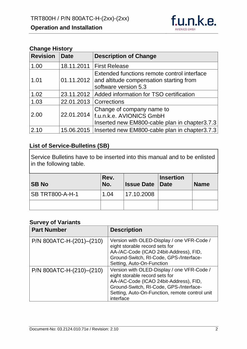
TRT800H PN 800ATC-H-(2xx)-(2xx)
Operation and Installation
3 Document-No 03212401071e Revision 210
Table of Contents
1 GENERAL 5
11 Symbols 5
12 Abbreviations 6
13 Customer Support 6
14 Features 7
15 Deviations and Important Notes 8
2 OPERATION 9
21 Controls 9
22 Switch ONOFF 11
23 Display - Indications 12
24 Display-Brightness 13
25 Flight-ID (FID) 13
251 Display Flight-ID 13
252 Configure Flight-ID 14
26 Transponder Mode selection 14
27 Squawk-Setting 15
28 VFR ndash Squawk 15
29 ID ndash Special Position Identification (SPI) ldquoSquawk Identrdquo 16
210 Error-Codes 16
3 INSTALLATION 17
31 Notes 17
32 Telecommunication data 17
33 Scope of Delivery 17
34 Unpacking and Inspecting of the Equipment 18
35 Mounting 18
36 Equipment Connections 19
361 Electrical Connections 19
362 Static Air Port 20
37 Wiring 20
371 Conductor Cross Section 20
372 Pin Assignment 21
373 Cable plan External Memory EM800 22
TRT800H PN 800ATC-H-(2xx)-(2xx)
Operation and Installation
4 Document-No 03212401071e Revision 210
38 Antenna 25
381 Antenna Selection 25
382 Installation Recommendation 25
383 Antenna Wiring 25
39 Post-Installation Check 26
310 Starting Up 27
311 Accessories 27
312 Drawings 28
3121 Dimensions 28
3122 Mounting Advices 28
4 Transponder SETTINGS 29
41 Overview 29
42 Display Configuration Summary 29
43 General settings 31
431 ICAO 24-Bit Aircraft Address (AA) 31
432 Aircraft Category (AC) 31
433 Flight-ID (FID) 32
434 Reply Information - Speed Category (RI) 33
44 Optional settings 33
441 Option Ground-Switch 33
442 Option Remote Header 34
443 Serial Interface (RS232) 34
444 Altitude CorrectionOffset 35
45 Setup Procedure 36
451 Setup Menu Control 36
452 Transponder configurationrecord structure 37
453 Transponder configurationrecord handling 37
454 General Setup 37
455 Altitude Correction Setup 41
5 APPENDIX 43
51 Technical Data 43
52 Environmental Conditions 45
53 DO-178B Open Problem Reports 46
TRT800H PN 800ATC-H-(2xx)-(2xx)
Operation and Installation
5 Document-No 03212401071e Revision 210
1 GENERAL
This manual contains information about the physical mechanical and electrical characteristics and about installation and operation of the Mode S Transponder TRT800H
The conditions and tests required for TSO approval of this article are minimum performance standards Those installing this article either on or within a specific type or class of aircraft must determine that the aircraft installation conditions are within the TSO standards which include any accepted integrated non-TSO function standards TSO articles and any accepted integrated non-TSO function(s) must have separate approval for installation in an aircraft The article may be installed only according to 14 CFR part 43 or the applicable airworthiness requirements This is an incomplete system (antenna is required) intended to provide the TSO functions specified in this Operation and Installation Manual section 51
11 Symbols
Advices whose non-observance can cause radiation damage to the human body or ignition of combustible materials
Advices whose non-observance can cause damage to the device or other parts of the equipment
Supplementary information
TRT800H PN 800ATC-H-(2xx)-(2xx)
Operation and Installation
6 Document-No 03212401071e Revision 210
12 Abbreviations
Abb Meaning Explanation
FID Flight ID Flight plan number or if not assigned registration number of aircraft
SPI Special Position Identification
Activation on request by controllers bdquoSquawk Identldquo transmits SPI Pulse for 18 seconds which highlights the respective traffic item on the controllers radar screen
AA Aircraft Address assigned ICAO 24-bit address
AC Aircraft Category Defines aircraft type according to specific categories
RI Reply Information Maximum airspeed
13 Customer Support
In order to facilitate a rapid handling of return shipments please follow the instructions of the input guide bdquoReshipment RMAldquo provided at the Service-Area within the funke AVIONICS GmbH web portal wwwfunkeavionicsde
Any suggestions for improvement of our manuals are welcome Contact servicefunkeavionicsde
Information on software updates is available at funke AVIONICS GmbH
TRT800H PN 800ATC-H-(2xx)-(2xx)
Operation and Installation
7 Document-No 03212401071e Revision 210
14 Features
In order to operate the Mode S transponder it is necessary to request an ICAO 24-bit Aircraft Address at the responsible national aviation authorities The received Code is assigned to the specific transponderaircraft and must be configured within the transponder The 24-bit address is stored in an external memory which allows the transponder being exchanged without requiring any further configuration (for detailed information refer to sections 431 and 454)
Class 1 Level 2es non-diversity Mode S transponder for ground based interrogations at 1030 MHz and response at 1090 MHz
Replies to (Secondary) Radar Interrogations
o Mode A replies with a Squawk (one of 4096 possible Codes eg flight plan number Squawk assigned by a controller or the VFR Squawk 7000)
o Mode C replies including encoded flight level
o Mode S replies including aircraft address and flight level
o Extended Squitter containing additional information on position and velocity
IDENT capability for activating the Special Position Identificationldquo-Pulse (SPI) for 18 seconds which is requested by the Controller bdquoSquawk Identldquo
Maximum flight level 35 000 ft maximum airspeed 250 kt
Display information contains Squawk code mode of operation and pressure altitude
Temperature compensated high precision piezo-resistive pressure sensor
RS-232 IO data port enabling connection with certain GPS-Receivers in order to support ADS-B Out
8 storable entries for AA-AC-Code FID Ground-Switch RI-Code and GPS-Interface-setting (stored in external memory TRT800EMxx)
Remote control unit interface
TRT800H PN 800ATC-H-(2xx)-(2xx)
Operation and Installation
8 Document-No 03212401071e Revision 210
15 Deviations and Important Notes
The following deviations have been granted by the FAA
The device is certified to FAA TSO-C112c in lieu of FAA TSO-C112d
Environmental Qualification Testing was performed according to RTCADO-160D in lieu of RTCADO-160F
The Software of this device was developed according to RTCA DO-178B Design Assurance Level D
The ADS-B function of this device has not been evaluated during the FAA TSO certification process other than to ensure non-interference Due to the SW assurance of DAL D the ADS-B function cannot be used in the US National Airspace
Connecting a GPS source will not comply to FAA certification requirements with regard to ADS-B
This device contains an altitude measuring device that has not been evaluated during the FAA TSO certification process other than to ensure non-interference
This feature must be evaluated for intended function during FAA installation approval
Compliance to RTCA DO-181D was verified by testing against EUROCAE ED-73C The two standards are technically identical with regard to the TRT800H
TRT800H PN 800ATC-H-(2xx)-(2xx)
Operation and Installation
9 Document-No 03212401071e Revision 210
2 OPERATION
21 Controls
ON OFF
bdquoSquawk Identldquo
Activate deactivate VFR
Change Active Standby
Squawk
Select Operation Mode
Cursor adjustment
Rotary Knob for adjusting values at the cursor position
active
Operation
Mode
standby Standby Squawk
Active Squawk
TRT800H PN 800ATC-H-(2xx)-(2xx)
Operation and Installation
10 Document-No 03212401071e Revision 210
IO ONOFF
Switch ON press button for approx 05 s
Switch OFFpress button for approx 3 s
VFR VFR
activatedeactivate VFR Squawk (press shortly)
store active Squawk as VFRVFRW-Squawk (press button 3 s rarr28)
CHANGE
change between active and standby-Squawk
works as cursor back button (opposite function of the cursor button) during entering values and also for navigating backwards through the configuration menu (rarr454)
ID IDENT
bdquoSquawk Identldquo sends Ident marking (SPI) for 18 s (rarr 29)
Enter Flight-ID (FID) setup (in standby mode press button for approx 5s)
MODE MODE Select transponder operational mode (rarr 26)
CURSOR Set position of Cursor
Rotary Knob
AdjustEnter values at current cursor position select options set standby Squawk (rarr 27)
TRT800H PN 800ATC-H-(2xx)-(2xx)
Operation and Installation
11 Document-No 03212401071e Revision 210
22 Switch ONOFF
Switch ON press IO for 05 s
Switch OFF press IO for 3 s
221 Display information after power up
After turning-on the display appears as follows (example)
If more than one configuration record is programmed the record selection menu appears (example)
Select the desired record (rotary switch) and confirm with MODE
If no external memory is connected or no 24bit address is defined the message ldquoCRADLE OFFrdquo appears In this case the device is working as ldquoMode AC onlyrdquo transponder
The transponder starts in STBY mode
2000 FL 030
STBY 7000
Cradle OFF
24D5F2 lt 000000 BE2343 000000 D4B3AA 000000 000000 000000
TRT800H V53
FPGA-Vers 102
Device Name
Software Version
Firmware Version
TRT800H PN 800ATC-H-(2xx)-(2xx)
Operation and Installation
12 Document-No 03212401071e Revision 210
23 Display - Indications
Value Meaning Remarks
7000 active Squawk
2000 Standby Squawk Could be changed with active Squawk by pressing
FL 030
FLerr
Flight Level
Invalid altitude measuring
Flight Level (in 100 ft steps)
Beyond -1000 35 000 ft C Mode gets inactive
ACS Operational Mode (STBY A-S ACS AC A)
Modes see section 26
IDT transmits Ident-Marking (SPI) ID (bdquoSquawk Identldquo) has been pressed ndash active for 18 s
Transponder replies
on Mode-S Mode-A or Mode-C interrogations
No indication on ADSB and squitter transmission
| Transponder is locked by a ground station and will be directly addressed
Lock Information (indicated below the diamond)
F
G
in-flight
on-ground
Ground-Switch-Info
(if installedavailable)
ACS
7000
TM
PLLTRX DC | BATDIM
IDT FL 030
STBY 2000 F
Passive Squawk
Active Squawk
Test mode indicatior
GND switch status
Operational Mode Standby
SPI indicator
Error indications
Reply indication
Lock out indication
Flight level
Backlight setup
Low battery ind
Operational Mode Active
TRT800H PN 800ATC-H-(2xx)-(2xx)
Operation and Installation
13 Document-No 03212401071e Revision 210
Value Meaning Remarks
Error indicators
PLL PLL Error Internal Error
TRX Transmit Failure Check antenna and wiring
DC Low internal voltage Internal error
FPG FPGA-Failure Internal error
BAT Battery Power too low maybe batterygenerator fault
24 Display-Brightness
In active mode (not standby) press for 2 s
Display indicates ldquoDIMrdquo Adjust brightness (DIM) with rotary knob
Return to normal operation press or wait 5 s
25 Flight-ID (FID)
The FID is an identifier required for Mode S Operation During future application of flight plans a FID could be assigned on a per flight basis If no FID is assigned (todayrsquos normal case) the registration marking of the aircraft should be used as FID The FID should not contain dashes or blanks The FID must not be confused with the 24-bit Aircraft Address
251 Display Flight-ID
Press MODE (repeatedly) until bdquoSTBYldquo appears
Press and hold ID while a counter is shown beside the active squawk During a few seconds Flight Identification is displayed
FID 02
A B C D E F G H
-
TRT800H PN 800ATC-H-(2xx)-(2xx)
Operation and Installation
14 Document-No 03212401071e Revision 210
252 Configure Flight-ID
Press MODE (repeatedly) until bdquoSTBYldquo appears
Press and hold ID while a counter is shown beside the active squawk Release ID when ldquoCHANGE FIDrdquo is displayed
Enter Flight-Id with cursor button and rotary knob
Press MODE to save and return to STBY
Please refer to section 454 for configuration of the 24-bit Address (AA) and Aircraft Category (AC)
26 Transponder Mode selection
Press MODE (repeatedly) to select from following Modes
STBY bdquoStandbyldquo Transponder does not respond to any interrogation Squitter and ADS-B output is not active
A C S bdquoMode A+C+Sldquo Standard condition transponder responds to mode A C and S interrogations
A ndash S bdquoMode A+S no Cldquo Altitude is not transmitted (neither on C nor on S requests) All other Mode-S data as well as Mode-A replies are transmitted
Enter FID left-aligned without any blanks or dashes () eg 12345621DEFAV for the marking D-EFAV The last remaining digits shall be filled with blanks
CHANGE FID
_ _ _ _ _ _ _ _ A B C D E F G H
- exit
TRT800H PN 800ATC-H-(2xx)-(2xx)
Operation and Installation
15 Document-No 03212401071e Revision 210
If no 24-bit address (AA) was defined or entered as ldquo000000ldquo the transponder operates as a Mode AC transponder in that case the following Modes are possible apart from Standby
A C ndash bdquoMode A+Cldquo Transponder replies only on Mode A and Mode-C interrogations
A ndash ndash bdquoMode Aldquo Transponder replies only on Mode A interrogations
In STBY (Standby) mode all transponder transmissions are disabled completely Therefore the transponder is not visible in this mode to air traffic control or the anti-collision systems onboard other aircrafts
Never use the STBY mode in flight unless you are requested to do so by air traffic control Always remember to put the transponder in active mode prior to take off
27 Squawk-Setting
The active Squawk is displayed in the upper line while the standby Squawk is presented at the lower line
Setting the Standby Squawk
Press to set the cursor (bdquo^ldquo) turn rotary knob to set numbers of the standby Squawk
Press to activate the Standby Squawk (this moves the current active Squawk into Standby)
28 VFR ndash Squawk
The transponder features a user-defined squawk code for VFR-flight (factory setting 7000)
Activate VFR-Squawk
Press VFR (bdquoVFRldquo is indicated) now the active Squawk is moved into Standby but not visible because the indication of the Standby Squawk is overlapped by bdquoVFRldquo
TRT800H PN 800ATC-H-(2xx)-(2xx)
Operation and Installation
16 Document-No 03212401071e Revision 210
Display Standby Squawk
Press VFR or or use the rotary knob (the VFR-Squawk remains active)
Example
VFR VFR
Now the Standby Squawk can be adjusted by using the rotary knob and activated with
In order to store the current active Squawk as new VFR-Squawk (replacing the factory setting 7000) Press and hold VFR until an bdquoSldquo is indicated (approx 3 s) after releasing the button bdquoVFRldquo is shown
29 ID ndash Special Position Identification (SPI) ldquoSquawk Identrdquo
Press ID to activate transmission of the special position identification pulse with every reply within 18 seconds ldquoIDTrdquo appears on the display
By pressing ID a special position identification pulse (SPI) is transmitted with every reply within 18 seconds which causes an accented marking on the Controllerrsquos screen The bdquoSpecial Position Identificationldquo has to be activated after the bdquoSquawk Identldquo request of the Controller
210 Error-Codes
Please refer to 23 Display - Indications for possible displayed errors
7000
FL 030
STBY 4700
7000
FL 030
STBY VFR
4700
FL 030
STBY 5600
TRT800H PN 800ATC-H-(2xx)-(2xx)
Operation and Installation
17 Document-No 03212401071e Revision 210
3 INSTALLATION
31 Notes
The following suggestions should be considered before installing
The assigned installation company will supply wiring For diagrams refer to 37 Wiring
Transponder External Memory all cables and antennas shall be installed according to bdquoFAA AC-14313-2A Acceptable Methods Techniques and Practices ndash Aircraft Alterationsldquo and the appropriate manufacturerrsquos instructions
32 Telecommunication data
Depending on your national telecommunications legislation the following data may be required when applying for the aircraft radio station license
Manufacturer funke AVIONICS GmbH
Type Designation TRT800H
EASA Number EASA21O269
Transmitter Power Output
126 W
Frequency 1090 MHz
Emission Designator 12M0M1D
33 Scope of Delivery
Item namenumber Description
TRT800H Transponder TRT800H
TRT800EMSS External Memory (Aircraft-Address-Adaptor with wiring)
M4X8ZSW (3 pieces) screw for panels up to 5 mm thickness
56S101A4 TNC antenna connector
03212401071e Manual bdquoOperation and Installationldquo
EASA Form 1
TRT800H PN 800ATC-H-(2xx)-(2xx)
Operation and Installation
18 Document-No 03212401071e Revision 210
34 Unpacking and Inspecting of the Equipment
Carefully unpack the equipment and inspect for transport damages If a damage claim has to be filed save the shipping container and all packing materials as evidence to your claim
35 Mounting
In cooperation with a maintenance shop location and kind of the installation are specified The maintenance shop can supply all cables Suitable sets of cables are available from funke AVIONICS GmbH
Select a position away from heat sources Provide space for adequate convection cooling
Leave sufficient space for the installation of cables and connectors
Avoid sharp bends and wiring close to control cables
Leave sufficient lead length for inspection or repair of the wiring of the connector (containing the memory) so that when the mounting hardware for the rear connectors is removed the assembly may be pulled forward several inches
Bend the harness at the rear connectors to inhibit water droplets (formed due to condensation) from collecting in the connector
For mounting detailsdrawing refer to chapter 3122 Mounting Advices
For storage or reshipment the original packaging should be used
TRT800H PN 800ATC-H-(2xx)-(2xx)
Operation and Installation
19 Document-No 03212401071e Revision 210
36 Equipment Connections
361 Electrical Connections
One 15 pin D-SUB miniature connector includes all electrical connections except for the antenna Use only an External Memory Adapter TRT800EMxx as this is part of the certification and includes a memory device in which the ICAO 24-bit Aircraft Address is stored
3611 Mutual Suppression
Other equipment on board (e g DME) may transmit in the same frequency band as the transponder
If such a device is installed a suppression wiring shall be installed in order to protect the receiving parts of the different devices from in-band transmissions
Mutual suppression is a synchronous pulse that is sent to the other equipment to suppress transmission of a competing transmitter for the duration of the pulse train transmission The transponder transmission may be suppressed by an external source and vice versa
To activate mutual suppression connect the SUPP_IO signal to the according signals of the other equipment
3612 Ground Switch
If an external Ground-Switch is connected to the transponder and activated in the setup the transponder can detect if the aircraft is airborne or on the ground This allows the transponder to automatically activate the Ground mode whenever the aircraft is on ground
In order to activate this feature the input bdquoFLY-GNDldquo must be connected to an external switch which connects the input pin with bdquoGNDldquo when the gear is weighted or remains open in the other case
This feature must additionally be activated in the Setup For details on configuration please refer to section 454
The (+UB)-wire has to protected by circuit breaker (2 Amp)
TRT800H PN 800ATC-H-(2xx)-(2xx)
Operation and Installation
20 Document-No 03212401071e Revision 210
3613 Auto-On
The Auto-On input allows to define how the transponder will behave when power is supplied to it
If the aircraft is equipped with a dedicated avionics master switch that switches the power supply to the transponder the pin Auto-On must be wired together with the UB+ pin to the avionic master switch The onoff button on the transponder is without function in that case The transponder will start automatically whenever power is supplied
On aircraft without such an avionics master switch the pin Auto-On must be left unconnected In this case the transponder must be switched on and off via the transponders onoff button on the front panel
362 Static Air Port
Install a silicon soft tube fitting the 5 mm static air hose at the backside of the transponder and secure plumbing with appropriate clamps
37 Wiring
371 Conductor Cross Section
Power Supply (Power GND) AWG20 (062 mmsup2)
Signals AWG22 (038 mmsup2)
The conductors must be approved for aircraft use
TRT800H PN 800ATC-H-(2xx)-(2xx)
Operation and Installation
21 Document-No 03212401071e Revision 210
372 Pin Assignment
The transponder may only be operated together with an external memory address adaptor TRT800EMxx
Pin Signal Remarks Adaptor
Typ(4)
TRT800
EM
Adaptor
Typ(4)
TRT800
EMSS
Adaptor Typ
TRT800
EMRS
1 GND -
2 Remote control(1) Input
3 EEPROM Signal TRT800EMxx internal
4 EEPROM Signal TRT800EMxx internal
5 TX RS-232 Serial Output
6 Switched +UB(1) Output
7 Remote control(1) Output
8 +UB power supply Input
9 GND -
10 EEPROM VCC TRT800EMxx internal
11 EEPROM GND TRT800EMxx internal
12 RX RS-232 Serial Input
13 Suppression Input Output
14 Auto-On(2) Input(2)
15 Fly-GND Switch(3) Input(3)
= in the plug and get out = in the plug and not get out ∕ = internal connection to the device
(1) SWITCHED +UB OUT Interface Remote control
May only be used for compatible funke AVIONICS devices Do not connect pins if interface is not used
(2) Auto-On Connect to +UB override front panel onoff button Leave unconnected to use front panel onoff button
(3) Ground Switch
FLY-GND
If an external Ground Switch is connected it must connect this pin to GND to indicate the on-ground condition Leave open otherwise
(4) Adaptors TRT800EM amp TRT800EMSS
Adaptor version does not provide full interface capability (see table for details)
TRT800H PN 800ATC-H-(2xx)-(2xx)
Operation and Installation
22 Document-No 03212401071e Revision 210
373 Cable plan External Memory EM800
3731 Cable plan TRT800EMRS (older version with interface remote)
to SN 90932013
DSUB 15pol
TRT800HTRT800A
lt PIN-5 gt
lt PIN-12gt
lt PIN-15gt
lt PIN-13gt
lt PIN-7 gt
lt PIN-2 gt
lt PIN-6 gt
lt PIN-1 gt
lt PIN-9 gt
lt PIN-8 gt
lt PIN-14gt
TXD
RXD
FLY_GND
SUPP_IO
GND
open
cable
ends
Remote Binder
Connector
female
white
black
yellow
red
shield
blue
red
brown
GND
+UB
AUTO-ON(2)(3)
black
white
red
yellow
shield
Binder Connector female
(solder side)
1 2 3 4 5 6 7 8
9 10 11 12 13 14 15
D-SUB Connector female
(solder side)
open
cable
ends
1 New interface available
-at TRT800H starting from SN 30430109 with SW V53
-at TRT800A starting with SW V53 2 New TRT800H interface starting from HW 60 3 port function not available at TRT800A
3
4 2
5 1
RMT-LIGHT
GND
RMT-TXD
RMT-SW+UB
RMT-RXD
RMT-TXD(1)
RMT-RXD(1)
RMT-SW+UB(2)(3)
RMT-LIGHT(2)
GND(1)
TRT800H PN 800ATC-H-(2xx)-(2xx)
Operation and Installation
23 Document-No 03212401071e Revision 210
3732 Cable plan TRT800EMRS (newer version with interface remote)
from SN 90932114
DSUB 15pol
TRT800HTRT800A
lt PIN-5 gt
lt PIN-12gt
lt PIN-15gt
lt PIN-13gt
lt PIN-7 gt
lt PIN-2 gt
lt PIN-6 gt
lt PIN-1 gt
lt PIN-9 gt
lt PIN-8 gt
lt PIN-14gt
TXD
RXD
FLY_GND
SUPP_IO
GND
open
cable
ends
Remote Binder
Connector
female
white
brown
yellow
green
shield
blue
red
brown
GND
+UB
AUTO-ON(2)(3)
brown
white
green
yellow
shield
Binder Connector female
(solder side)
1 2 3 4 5 6 7 8
9 10 11 12 13 14 15
D-SUB Connector female
(solder side)
open
cable
ends
1 New interface available
-at TRT800H starting from SN 30430109 with SW V53
-at TRT800A starting with SW V53 2 New TRT800H interface starting from HW 60 3 port function not available at TRT800A
3
4 2
5 1
RMT-LIGHT
GND
RMT-TXD
RMT-SW+UB
RMT-RXD
RMT-TXD(1)
RMT-RXD(1)
RMT-SW+UB(2)(3)
RMT-LIGHT(2)
GND(1)
TRT800H PN 800ATC-H-(2xx)-(2xx)
Operation and Installation
24 Document-No 03212401071e Revision 210
3733 Cable plan TRT800EMSS (newer version without interface remote)
from SN 91032115
The External ndash Memory ndash Address - Adapter TRT800EMxx contains electronic parts and must not be opened Opening or modifying the connector leads to the loss of airworthiness certification
DSUB 15pol
TRT800HTRT800A
lt PIN-5 gt
lt PIN-12gt
lt PIN-15gt
lt PIN-13gt
lt PIN-1 gt
lt PIN-9 gt
lt PIN-8 gt
lt PIN-14gt
TXD
RXD
FLY_GND
SUPP_IO
GND
open
cable
ends
white
brown
yellow
green
shield
blue
red
brown
GND
+UB
AUTO-ON(2)(3)
open
cable
ends
2 New TRT800H interface starting from HW 60 3 port function not available at TRT800A
1 2 3 4 5 6 7 8
9 10 11 12 13 14 15
D-SUB Connector female
(solder side)
TRT800H PN 800ATC-H-(2xx)-(2xx)
Operation and Installation
25 Document-No 03212401071e Revision 210
38 Antenna
381 Antenna Selection
Recommended antennas see section 311 Accessories
Choose an antenna type compatible with the vehicle and the mounting location
Specified features depend on proper installation of the antenna
The radiation pattern needs to be verified considering aircraft type and mounting location
The electrical interference between the antenna and any other equipment must be taken into account in such a way that no reduction of the performance of any other system will occur
Install only certified antennas
382 Installation Recommendation
Take note of the antenna manufacturerrsquos instructions
The usually deployed Dipole- or Blade antennas necessarily require a high frequency capable solid metal ground plane at the antenna base
For installation in composite aircrafts ground planes are to be added The ground plane should be as large as possible but in any case not smaller than 10 cm x 10 cm If in doubt please contact the aircraft manufacturer
Keep away three feet from any other antenna
Pursue mounting in vertical position under the belly in flight direction
383 Antenna Wiring
Suitable antenna cables see section 311 Accessories
Keep wiring as short as possible
The smallest cable bend radius is 10cm Avoid sharp bends
Keep away from an ADF antenna cable at least 12 inches
Electrical connections to the antenna shall be protected against moisture to avoid loss of efficiency
TRT800H PN 800ATC-H-(2xx)-(2xx)
Operation and Installation
26 Document-No 03212401071e Revision 210
39 Post-Installation Check
All steering and control functions of the aircraft are to be examined in order to exclude disturbances by the wiring
The most important factor in the transponder configuration is the setting of the ICAO address (see section 454)
Attenuation from antenna to transponder at 1090 MHz must not exceed 15 dB
A certified maintenance shop must verify proper operation of the transponder by testing in accordance with Appendix F of ldquo14 CFR Part 43 ndash ATC Transponder Tests and Inspectionsrdquo
TRT800H PN 800ATC-H-(2xx)-(2xx)
Operation and Installation
27 Document-No 03212401071e Revision 210
310 Starting Up
Turn the transponder on with IO After start-up the following screens appear
311 Accessories
Part Number Description
TRKABEL1 Antenna cable 10 m (32 ft) TNC BNC
TRKABEL2 Antenna cable 25 m (82 ft) TNC BNC
TRKABEL3 Antenna cable 40 m (132 ft) TNC BNC
TRKABEL4 Antenna cable 65 m (213 ft) TNC BNC
TRT800EMRS External-Memory (Aircraft-Address-Adaptor) Connection cable with interface TRT-Remote control
CI-105 TransponderDME Antenna TSO C66b C74c
CI105 Comant Industries Inc
Height 325rdquo Weight 90 g (02 lbs)
AV22 Transponder Rod antenna TSO C74c
AV-22 R A Miller Industries
The TRT800H starts in standby mode (indicated with STBY) In order to change into operational mode (indicated with ACS) press MODE If ground switch is connected and status ldquoin flightrdquo is selected TRT800H starts in active mode
Very important is the correct configuration of the 24bit Aircraft-Address (see 454 General Setup)
TRT800H V53
FPGA-Vers 102
2000 FL 030
STBY 7000
TRT800H PN 800ATC-H-(2xx)-(2xx)
Operation and Installation
28 Document-No 03212401071e Revision 210
312 Drawings
3121 Dimensions
20mm15 mm
170 mm
TRT800TRT800H
65 mm
65
mm
Oslash 57 mm
Static Air
Antenna
PowerRS232
3122 Mounting Advices
Connections Area
8
0 m
m
Panel Cut-out
470 mm
470
mm
575 mm
4 x Oslash 4 mm
Oslash
Connector (plug) has to be clamped with both spring locks
No screws may be turned in more than max 15mm into the device ndash even if no hard limit is noticeable
Fixing clips (spring) left right
TRT800H PN 800ATC-H-(2xx)-(2xx)
Operation and Installation
29 Document-No 03212401071e Revision 210
4 TRANSPONDER SETTINGS
41 Overview
The TRT800H is capable of storing the following information
ICAO 24-Bit Aircraft-Address (AA)
Aircraft Category (AC)
Flight Identification (FID)
Ground-Switch (YesNo)
Speed Category (RI)
RS232 Interface Configuration
All of these data are configurable in the Setup and are stored in the external memory module integrated within the housing of the D-Sub connector (included in the delivery)
The cable with this connector shall remain in the aircraft even if the unit is removed to ensure that the ICAO 24bit aircraft address is fixed to the aircraft
Additionally the following usertransponder related settings are stored transponder internally
Active Squawk
Passive Squawk
VFR Squawk
Altitude offset
Display brightness
42 Display Configuration Summary
Transponder provides the opportunity to show summary of complete current settings To access configuration summary pages push and hold
ID in Standby mode Release ID if ldquoSHOW SETUPrdquo is displayed The summary is subdivided into the following pages
TRT800H PN 800ATC-H-(2xx)-(2xx)
Operation and Installation
30 Document-No 03212401071e Revision 210
Page 1
Aircraft Address
Aircraft Category
Flight Identification
MODE
Page 2 Speed Category
Ground Switch option
Remote Header option
MODE
Page 3 RS-232 Settings
Protocol baud rate position (if available)1
MODE
Page 4 Altitude correction settings
(part 1)
MODE
Page 5 Altitude correction settings
(part 2)
Note 1 Position data will only be displayed if
a GPS protocol is set as interface protocol (NMEA FREEFLIGHT AR-NAV)
18000 ft 0ft 25000 ft + 100ft 35000 ft - 50ft
exit
ALTITUDE CORRECTION 2000 ft 0ft 10000 ft + 100ft next
RS-232 NMEA Baud 4800 Pos 481 99 next
Speed Cat 8 Ground Sw YES Remote Hd NO next
AA F E 1 2 3 4 AC 1 9 FID 4 4 E 1 2 3 next
TRT800H PN 800ATC-H-(2xx)-(2xx)
Operation and Installation
31 Document-No 03212401071e Revision 210
GPS receiver is connected and transmits data (if not ldquoPos no datardquo is displayed)
a valid position is transmitted (if not ldquoPos wrong datardquo is displayed)
While configuration summary page is displayed no new position data will be processed
43 General settings
431 ICAO 24-Bit Aircraft Address (AA)
Ask your national aviation authority (e g in Germany LBA Referat B5 Department ldquoVerkehrszulassungrdquo) how to obtain the AA In the case of aerial sports equipment the contact point would be the respective associations Only the assigned AA has to be used and must not be modified at any time because a duplicate address would jeopardize the data surveillance and integrity figures of Mode S
If no AA is stored after power on the display shows ldquoCRADLE OFFrdquo and the transponder operates in Mode AC
(Configuration of the AA see section 454)
432 Aircraft Category (AC)
Code Description Code Description
11 Emergency Vehicle 1C Ultra-Light Paraglider
12 Service Vehicle 1E Drone
19 Glider 21 Aircraft (D-Exxx) lt 15500 lbs Motor Glider (D-Kxxx)
1A Balloon amp Airship 22 Aircraft ge 15500 lbslt 75000 lbs
1B Paratrooper 27 Rotorcraft
Only one of the Codes mentioned in the table above must be used
Setuprarr454
Setuprarr454
TRT800H PN 800ATC-H-(2xx)-(2xx)
Operation and Installation
32 Document-No 03212401071e Revision 210
433 Flight-ID (FID)
Per ICAO regulation Mode-S data must contain a valid flight identification (FID) to ensure that the correlation between flight plan and radar data will work automatically
FID setting is required to correspond to the aircraft identification that has been specified at item 7 of the ICAO flight plan It contains seven characters at a maximum (left-aligned no additional zeros dashes or spacesblanks)
For an aircraft using a company call sign the Flight-ID mostly consists of the ICAO three-letter designator for the aircraft operator followed by an identification code eg KLM511 BAW213 JTR25
If no company call sign is used or no flight plan is filed the default FID to be set consists of the registration marking of the aircraft (eg DEABC) with no dashes spacesblanks or additional zeros even if they are included in the registration marking on the aircraft (tail number) While entering the FID into the transponder the last remaining digits must be filled with blanks
The ICAO Flight Plan only specifies 7 characters for FID funke AVIONICS reserves 8 characters as stated in ED-73B for further expansion of the flight plan
The user shall only program 7 characters for FID
Setuprarr454
TRT800H PN 800ATC-H-(2xx)-(2xx)
Operation and Installation
33 Document-No 03212401071e Revision 210
434 Reply Information - Speed Category (RI)
Besides AA AC and FID another important part of the Mode-S data is the Speed Category of the respective aircraft This speed category shall be configured in the setup and must contain one of the following codes
Code Description
08 No maximum airspeed data available
09 Maximum airspeed le 75 kt
10 75 kt gt maximum airspeed le 150 kt
11 150 kt gt maximum airspeed le 300 kt
12 300 kt gt maximum airspeed le 600 kt
13 600 kt gt maximum airspeed le 1200 kt
14 Maximum airspeed gt 1200 kt
15 Not assigned
44 Optional settings
441 Option Ground-Switch
If a ground switch is connected (and enabled in setup) the transponder is able to determine on-ground and in-flight state On-ground state is activated automatically once the gear touches the ground On-ground state is indicated on display by symbol G (apart from lsquoFrsquo for In-flight-state)
In On-ground-state the transponder will reply differently to certain addressed interrogations Also the transmission rate of some periodically sent data (squitters ADS-B) is reduced This allows ATC to distinguish between airborne aircraft and those on the ground and it reduces the Mode S channel load
For small aircraft authorities normally do not require such a ground switch In this case the transponder will use the same data formats on the ground as in the airborne state
Setuprarr454 Wiringrarr373
Setuprarr454
TRT800H PN 800ATC-H-(2xx)-(2xx)
Operation and Installation
34 Document-No 03212401071e Revision 210
442 Option Remote Header
The transponder provides a TRT800RT remote control interface If a remote header TRT800RT is connected transponder can be remote controlled via this interface Remote interface provides control of all standard user inputs available during standard operational mode For more information see TRT800RT manual Remote control interface de-activation is setup configurable Remote control interface must only be connected to TRT800RT
443 Serial Interface (RS232)
Using serial interface a GPS receiver can be connected to broadcast own position via ADS-B Out position message Position could be received by other appropriately equipped aircrafts and processed for collision avoidance ADS-B Out functionality
The ADS-B function of this device has not been evaluated during the FAA TSO certification process other than to ensure non-interference Due to the SW assurance of DAL D the ADS-B function cannot be used in the US National Airspace Connecting a GPS source will not comply to FAA certification requirements with regard to ADS-B
Supported formatsprotocols are
Option Description Baud rate
FREEFLIGHT GPSWAAS Sensor 1201
NexNav NNL 3101
19200
AR-NAV Bendix King
KLN 89B KLN 94 ldquoStandard RS232 Sentencerdquo
KMD 150 ldquoSentence Type 1rdquo
Garmin 400 Series ldquoSentence Type 1rdquo (with and without altitude data)
9600
NMEA NMEA-Format data format RMC is expected
4800
Setuprarr454 Wiringrarr373
Setuprarr454 Wiringrarr373
TRT800H PN 800ATC-H-(2xx)-(2xx)
Operation and Installation
35 Document-No 03212401071e Revision 210
Option Description Baud rate
FAVISIA Glass Cockpit support
FAVISIA Data format to be processed in FAVISIA avionics suite
-
FAVISIA+GPS Data format to be processed in FAVISIA avionics suite (output) and additional processing of incoming NMEA GPS-Receiver position data to support the ADS-B Out functionality
4800
Other
Comm-AB-support
Data format for special purpose An additional data link processor allows COMM-AB operation and processing of the position information of a flight management system simultaneously
38400
Disabled No communication via RS232 interface -
444 Altitude CorrectionOffset
The TRT800H has an integrated temperature compensated high-precision pressure sensor This sensor is factory-calibrated so that it will yield accurate flight level (uncorrected pressure altitude) within the entire altitude range
However due to differences in calibration of the TRT800H pressure sensor and the altimeter in the cockpit it may become necessary to adjust the TRT800H pressure readings so that the value indicated and transmitted by the TRT800H corresponds to the indication of the primary altimeter seen by the pilot within 125 feet (as specified in ETSO C88aSAE AS 8003)
Setting for all described GPS-systems
1 2 position messages per 2 sec
Setuprarr455
TRT800H PN 800ATC-H-(2xx)-(2xx)
Operation and Installation
36 Document-No 03212401071e Revision 210
The check for correspondence between the primary altimeter and the TRT800H is usually performed every 24 months as part of the aircrafts altimeter checks
Altitude correction is based on setup configurable offset values at five interpolation points ( 2000 8000 18000 25000 and 35000 ft)The offset value itself is limited to a range from -100 to + 100ft at each point (10ft steps)
45 Setup Procedure
Programming of the ICAOA 24-bit Aircraft Address and of the Aircraft Category shall be executed by qualified personnel only
A wrong Aircraft Address or Flight ID may cause serious problems ATC or with ACASTCAS systems
Pilot and owner are responsible for correctly set transponder data
451 Setup Menu Control
In order to access the functions described in the following paragraphs push and hold ID in Standby mode Release ID if desired counter value menu name is displayed to enter the menu The following menu entries are selectable
Count Displayed Name Function
03 FID FID is displayed
48 CHANGE FID Enter FID setup page
913 SHOW SETUP Enter setup summary listed on different pages (no changes possible)
2528 ENTER SETUP Enter transponder general configuration pages
3134 ALTITUDE CORRECTION
Enter altitude correction menu
TRT800H PN 800ATC-H-(2xx)-(2xx)
Operation and Installation
37 Document-No 03212401071e Revision 210
452 Transponder configurationrecord structure
Aircraft related parts of transponder configuration are stored in one out of eight possible records (record=presetting) Each record contains the following information
Aircraft Address (AA 24bit)
Aircraft category (AC)
Flight identification (FID 6-8 numbersletters)
RS-232 Interface setting (eg GPS protocol)
Ground-Switch setting (Installed YesNo)
Speed category (RI) of the respective aircraft
Remote Header setting (Installed YesNo)
User related settings (eg squawk codes display brightness) are stored once in one global record (transponder internally)
453 Transponder configurationrecord handling
At least one record is stored in external memory Up to 8 records can be additional be applied during setup process
If more than one record is applied the active record must be selected out of a list (determined by FID) during start-up of the transponder
Previously applied records can be deleted again by filling FID with zerorsquos only
454 General Setup
Any menu item can be passed by MODE If no changes are made the original settings will remain stored Modification of one menu item does not impact the others No entries will be deleted
TRT800H PN 800ATC-H-(2xx)-(2xx)
Operation and Installation
38 Document-No 03212401071e Revision 210
Step Display (Example)
1 Start-up Transponder
2 Ensure the transponder-mode is bdquoSTBYldquo If necessary change the mode by pressing MODE
3 Press ID A counter is shown at the upper-right corner Hold ID till ldquoENTER SETUPrdquo is displayed
4 After release of ID the first setup menu is displayed
5 helliphellipselect position (^)
rotary knobchange value
MODE
6 With the rotary knob you can select bdquoyesldquo if a Ground Switch is installed if not select ldquonordquo and proceed with step 7
MODE
Record 1
GND Switch YesNo
next
AA EF123456
AC 18
FID ^BCDEFG
next
AA EF123456
AC 18
FID ABCDEFG
next
ENTER SETUP 26
2000 FL 030
STBY 7000
TRT800H PN 800ATC-H-(2xx)-(2xx)
Operation and Installation
39 Document-No 03212401071e Revision 210
Step Display (Example)
7 At this stage the respective speed category shall be selected by using the rotary knob
MODE
8 At this stage a GPS receiver for ADS-B Out can be selected (Selectable by rotary knob)
MODE
9 At this stage remote interface for communication between TRT800H and remote header can be activated (Selectable by rotary knob)
Remote interface must only be activated if a remote header is connected
MODE
10 With ID further Records can now be created and configured as described in the aforementioned steps At start-up of the transponder one of the defined records with all associated configurations need to be selected
MODE
Records ID=Edit Records
EXIT
Record 1
REMOTE Header YesNo
next
Record 1
GPSINTEXT NMEA
next
Record 1
Speed Cat 08-15
next
TRT800H PN 800ATC-H-(2xx)-(2xx)
Operation and Installation
40 Document-No 03212401071e Revision 210
Step Display (Example)
11 You have now left the configuration mode and are back in normal operation
12 Switch off the transponder
13 Switch on the transponder Your ICAO 24-Bit Aircraft Address is now stored
TRT800H V53
FPGA-Vers 102
2000 FL 030
STBY 7000
TRT800H PN 800ATC-H-(2xx)-(2xx)
Operation and Installation
41 Document-No 03212401071e Revision 210
455 Altitude Correction Setup
Altitude correction setup shall be executed by qualified personnel only
Pilot and owner are responsible for correctly set altitude offset values
The usesetting of altitude correction values is only necessary in exceptional cases (see 444 for details)
Altitude correction is based on five interpolation points ( 2000 10000 18000 25000 and 35000 ft)The offset value at each interpolation point can be adjusted in a range from -100 to + 100ft at each point (10ft steps) Offset values set to zero at each interpolation point deactivates altitude correction (defaultfactory setting)
Step Display (Example)
1 Start-up Transponder
2 Ensure the transponder-mode is bdquoSTBYldquo If necessary change the mode by pressing MODE
3 Press ID A counter is shown at the upper-right corner Hold ID till ldquoALTITUDE OFFSETrdquo is displayed
ALTITUDE OFFSET 33
2000 FL 030
STBY 7000
Descriptionrarr444
TRT800H PN 800ATC-H-(2xx)-(2xx)
Operation and Installation
42 Document-No 03212401071e Revision 210
Step Display (Example)
4 After release of ID the first altitude level + corresponding offset value is displayed
5 Change offset value with rotary knob
MODE
6 (9) Repeat last step for another 4 altitude levels 10000ft 18000ft 25000ft 35000ft
MODE
10 You have now left the configuration mode and are back in normal operation
Switch off the transponder
11 Switch on the transponder New altitude offset values will now be used for altitude calculation
Altitude 10000 ft
Offset 0 ft
nextexit
Altitude 2000 ft
Offset 0 ft
next
TRT800H V53
FPGA-Vers 102
2000 FL 030
STBY 7000
Altitude 2000 ft
Offset 0 ft
next
TRT800H PN 800ATC-H-(2xx)-(2xx)
Operation and Installation
43 Document-No 03212401071e Revision 210
5 APPENDIX
51 Technical Data
Compliance CS-ETSO-2C112a
EASA21O269
FAA TSO-C112c
Applicable Documents CS-ETSO-2C112a
FAA TSO-C112c
EUROCAE ED-73C Class 1 Level 2es
RTCA DO-181D Class 1 Level 2es
EUROCAE ED-26
RTCA DO-160D
RTCA DO-178B Software-Level D
Temperature Ranges
Operation -20 degC to +55 degC for 30 min +70degC
Storage -55 degC to +85 degC
Altitude Range le 35 000 ft
Speed Range le 250 kt (TAS)
Shock 6 G Operation
20 G crash safety
Environmental Categories RTCA DO-160D EnvCat [C1Z]CAA[SM]XXXXXXZBAAA[TT]M[B3F3]XXA
Power Supply 138 VDC (10 VDC 16 VDC)
040 A 138 VDC (typ)
070 A 138 VDC (max)
10 W (max)
TRT800H PN 800ATC-H-(2xx)-(2xx)
Operation and Installation
44 Document-No 03212401071e Revision 210
Fuse External 2A-slow-blow fuse
Mounting Panel cut-out d=575 mm
Weight 06 kg (132 lbs)
Receiver Characteristics
Sensitivity
RF input power level resulting in a 90 reply rate
A MTL for ATCRBS and ATCRBSMode S All-Call interrogations -74 dBm plusmn3 dB
B MTL for Mode S interrogations -74 dBm plusmn 3 dB
Reply transmission frequency
1090 plusmn 1 MHz
RF Peak Power Output 21 dBW (126 W) at antenna base (with maximum cable attenuation of 15 dB)
Squitter (ADS-B) transmitted at random intervals uniformly distributed over the range from 08 to 12 seconds full self-verification of data and occurrence
Mode S Elementary Surveillance
ICAO 24-bit Aircraft Address (Hex-Code)
aircraft address as assigned by national aviation authority
FID Flight ID Flight Plan call sign or aircraft registration marking
Capability Report Reports the available data and means by which the transponder can report
Pressure Altitude Up to 35 000 ft in 25 ft increments
Flight Status in-flight on-ground
Mode S Enhanced Surveillance
Level 2es Comm-A Comm-B 56112-Bit-Messages
SI-capability
TRT800H PN 800ATC-H-(2xx)-(2xx)
Operation and Installation
45 Document-No 03212401071e Revision 210
52 Environmental Conditions
Characteristic DOndash160D Section Cat Condition
Temperature Altitude 40
C1
Low ground survival temperature
451 ndash 55degC
Low operating temperature 451 ndash 20degC
High ground survival Temperature
452 + 85degC
High Short-time Operating Temperature
452 + 70degC
High Operating Temperature 453 + 55degC
In-Flight Loss of Cooling 454 Z No auxiliary cooling required
Altitude 461 C1 35 000 ft
Temperature Variation 50 C 2degC change rate minimum per minute
Humidity 60 A
Shock 70 A
6 G operational shocks
20 G Crash Safety
Test Type R in all 6 directions
Vibration 80 S Vibration Curve M
Explosion Proofness 90 X No test required
Water Proofness 100 X No test required
Fluids Susceptibilities 110 X No test required
Sand and Dust 120 X No test required
Fungus Resistance 130 X No test required
Salt Spray 140 X No test required
Magnetic Effect 150 Z Less than 03 m
Power Input (DC) 160 B
Voltage Spike Conducted 170 A
Audio Frequency Conducted Susceptibility
180 A
TRT800H PN 800ATC-H-(2xx)-(2xx)
Operation and Installation
46 Document-No 03212401071e Revision 210
Characteristic DOndash160D Section Cat Condition
Induced Signal Susceptibility 190 A
Radio Frequency Susceptibility
200 TT
Emission of RF Energy 210 M
Lightning Induced Transient Susceptibility
220 B3F3
Lightning Direct Effects 230 X No test required
Icing 240 X No test required
Electrostatic Discharge (ESD) 250 A
53 DO-178B Open Problem Reports
There are no open problem reports for the software of this device
TRT800H PN 800ATC-H-(2xx)-(2xx)
Operation and Installation
47 Document-No 03212401071e Revision 210
Notes
f funke funke means ndash fabrication utilities network know-how engineering
funke AVIONICS GmbH Heinz-Strachowitz-Str 4
DE-86807 Buchloe Germany
phone +49-8241 80066 0
fax +49-8241 80066 99 E-mail
servicefunkeavionicsde wwwfunkeavionicsde
TRT800H PN 800ATC-H-(2xx)-(2xx)
Operation and Installation
5 Document-No 03212401071e Revision 210
1 GENERAL
This manual contains information about the physical mechanical and electrical characteristics and about installation and operation of the Mode S Transponder TRT800H
The conditions and tests required for TSO approval of this article are minimum performance standards Those installing this article either on or within a specific type or class of aircraft must determine that the aircraft installation conditions are within the TSO standards which include any accepted integrated non-TSO function standards TSO articles and any accepted integrated non-TSO function(s) must have separate approval for installation in an aircraft The article may be installed only according to 14 CFR part 43 or the applicable airworthiness requirements This is an incomplete system (antenna is required) intended to provide the TSO functions specified in this Operation and Installation Manual section 51
11 Symbols
Advices whose non-observance can cause radiation damage to the human body or ignition of combustible materials
Advices whose non-observance can cause damage to the device or other parts of the equipment
Supplementary information
TRT800H PN 800ATC-H-(2xx)-(2xx)
Operation and Installation
6 Document-No 03212401071e Revision 210
12 Abbreviations
Abb Meaning Explanation
FID Flight ID Flight plan number or if not assigned registration number of aircraft
SPI Special Position Identification
Activation on request by controllers bdquoSquawk Identldquo transmits SPI Pulse for 18 seconds which highlights the respective traffic item on the controllers radar screen
AA Aircraft Address assigned ICAO 24-bit address
AC Aircraft Category Defines aircraft type according to specific categories
RI Reply Information Maximum airspeed
13 Customer Support
In order to facilitate a rapid handling of return shipments please follow the instructions of the input guide bdquoReshipment RMAldquo provided at the Service-Area within the funke AVIONICS GmbH web portal wwwfunkeavionicsde
Any suggestions for improvement of our manuals are welcome Contact servicefunkeavionicsde
Information on software updates is available at funke AVIONICS GmbH
TRT800H PN 800ATC-H-(2xx)-(2xx)
Operation and Installation
7 Document-No 03212401071e Revision 210
14 Features
In order to operate the Mode S transponder it is necessary to request an ICAO 24-bit Aircraft Address at the responsible national aviation authorities The received Code is assigned to the specific transponderaircraft and must be configured within the transponder The 24-bit address is stored in an external memory which allows the transponder being exchanged without requiring any further configuration (for detailed information refer to sections 431 and 454)
Class 1 Level 2es non-diversity Mode S transponder for ground based interrogations at 1030 MHz and response at 1090 MHz
Replies to (Secondary) Radar Interrogations
o Mode A replies with a Squawk (one of 4096 possible Codes eg flight plan number Squawk assigned by a controller or the VFR Squawk 7000)
o Mode C replies including encoded flight level
o Mode S replies including aircraft address and flight level
o Extended Squitter containing additional information on position and velocity
IDENT capability for activating the Special Position Identificationldquo-Pulse (SPI) for 18 seconds which is requested by the Controller bdquoSquawk Identldquo
Maximum flight level 35 000 ft maximum airspeed 250 kt
Display information contains Squawk code mode of operation and pressure altitude
Temperature compensated high precision piezo-resistive pressure sensor
RS-232 IO data port enabling connection with certain GPS-Receivers in order to support ADS-B Out
8 storable entries for AA-AC-Code FID Ground-Switch RI-Code and GPS-Interface-setting (stored in external memory TRT800EMxx)
Remote control unit interface
TRT800H PN 800ATC-H-(2xx)-(2xx)
Operation and Installation
8 Document-No 03212401071e Revision 210
15 Deviations and Important Notes
The following deviations have been granted by the FAA
The device is certified to FAA TSO-C112c in lieu of FAA TSO-C112d
Environmental Qualification Testing was performed according to RTCADO-160D in lieu of RTCADO-160F
The Software of this device was developed according to RTCA DO-178B Design Assurance Level D
The ADS-B function of this device has not been evaluated during the FAA TSO certification process other than to ensure non-interference Due to the SW assurance of DAL D the ADS-B function cannot be used in the US National Airspace
Connecting a GPS source will not comply to FAA certification requirements with regard to ADS-B
This device contains an altitude measuring device that has not been evaluated during the FAA TSO certification process other than to ensure non-interference
This feature must be evaluated for intended function during FAA installation approval
Compliance to RTCA DO-181D was verified by testing against EUROCAE ED-73C The two standards are technically identical with regard to the TRT800H
TRT800H PN 800ATC-H-(2xx)-(2xx)
Operation and Installation
9 Document-No 03212401071e Revision 210
2 OPERATION
21 Controls
ON OFF
bdquoSquawk Identldquo
Activate deactivate VFR
Change Active Standby
Squawk
Select Operation Mode
Cursor adjustment
Rotary Knob for adjusting values at the cursor position
active
Operation
Mode
standby Standby Squawk
Active Squawk
TRT800H PN 800ATC-H-(2xx)-(2xx)
Operation and Installation
10 Document-No 03212401071e Revision 210
IO ONOFF
Switch ON press button for approx 05 s
Switch OFFpress button for approx 3 s
VFR VFR
activatedeactivate VFR Squawk (press shortly)
store active Squawk as VFRVFRW-Squawk (press button 3 s rarr28)
CHANGE
change between active and standby-Squawk
works as cursor back button (opposite function of the cursor button) during entering values and also for navigating backwards through the configuration menu (rarr454)
ID IDENT
bdquoSquawk Identldquo sends Ident marking (SPI) for 18 s (rarr 29)
Enter Flight-ID (FID) setup (in standby mode press button for approx 5s)
MODE MODE Select transponder operational mode (rarr 26)
CURSOR Set position of Cursor
Rotary Knob
AdjustEnter values at current cursor position select options set standby Squawk (rarr 27)
TRT800H PN 800ATC-H-(2xx)-(2xx)
Operation and Installation
11 Document-No 03212401071e Revision 210
22 Switch ONOFF
Switch ON press IO for 05 s
Switch OFF press IO for 3 s
221 Display information after power up
After turning-on the display appears as follows (example)
If more than one configuration record is programmed the record selection menu appears (example)
Select the desired record (rotary switch) and confirm with MODE
If no external memory is connected or no 24bit address is defined the message ldquoCRADLE OFFrdquo appears In this case the device is working as ldquoMode AC onlyrdquo transponder
The transponder starts in STBY mode
2000 FL 030
STBY 7000
Cradle OFF
24D5F2 lt 000000 BE2343 000000 D4B3AA 000000 000000 000000
TRT800H V53
FPGA-Vers 102
Device Name
Software Version
Firmware Version
TRT800H PN 800ATC-H-(2xx)-(2xx)
Operation and Installation
12 Document-No 03212401071e Revision 210
23 Display - Indications
Value Meaning Remarks
7000 active Squawk
2000 Standby Squawk Could be changed with active Squawk by pressing
FL 030
FLerr
Flight Level
Invalid altitude measuring
Flight Level (in 100 ft steps)
Beyond -1000 35 000 ft C Mode gets inactive
ACS Operational Mode (STBY A-S ACS AC A)
Modes see section 26
IDT transmits Ident-Marking (SPI) ID (bdquoSquawk Identldquo) has been pressed ndash active for 18 s
Transponder replies
on Mode-S Mode-A or Mode-C interrogations
No indication on ADSB and squitter transmission
| Transponder is locked by a ground station and will be directly addressed
Lock Information (indicated below the diamond)
F
G
in-flight
on-ground
Ground-Switch-Info
(if installedavailable)
ACS
7000
TM
PLLTRX DC | BATDIM
IDT FL 030
STBY 2000 F
Passive Squawk
Active Squawk
Test mode indicatior
GND switch status
Operational Mode Standby
SPI indicator
Error indications
Reply indication
Lock out indication
Flight level
Backlight setup
Low battery ind
Operational Mode Active
TRT800H PN 800ATC-H-(2xx)-(2xx)
Operation and Installation
13 Document-No 03212401071e Revision 210
Value Meaning Remarks
Error indicators
PLL PLL Error Internal Error
TRX Transmit Failure Check antenna and wiring
DC Low internal voltage Internal error
FPG FPGA-Failure Internal error
BAT Battery Power too low maybe batterygenerator fault
24 Display-Brightness
In active mode (not standby) press for 2 s
Display indicates ldquoDIMrdquo Adjust brightness (DIM) with rotary knob
Return to normal operation press or wait 5 s
25 Flight-ID (FID)
The FID is an identifier required for Mode S Operation During future application of flight plans a FID could be assigned on a per flight basis If no FID is assigned (todayrsquos normal case) the registration marking of the aircraft should be used as FID The FID should not contain dashes or blanks The FID must not be confused with the 24-bit Aircraft Address
251 Display Flight-ID
Press MODE (repeatedly) until bdquoSTBYldquo appears
Press and hold ID while a counter is shown beside the active squawk During a few seconds Flight Identification is displayed
FID 02
A B C D E F G H
-
TRT800H PN 800ATC-H-(2xx)-(2xx)
Operation and Installation
14 Document-No 03212401071e Revision 210
252 Configure Flight-ID
Press MODE (repeatedly) until bdquoSTBYldquo appears
Press and hold ID while a counter is shown beside the active squawk Release ID when ldquoCHANGE FIDrdquo is displayed
Enter Flight-Id with cursor button and rotary knob
Press MODE to save and return to STBY
Please refer to section 454 for configuration of the 24-bit Address (AA) and Aircraft Category (AC)
26 Transponder Mode selection
Press MODE (repeatedly) to select from following Modes
STBY bdquoStandbyldquo Transponder does not respond to any interrogation Squitter and ADS-B output is not active
A C S bdquoMode A+C+Sldquo Standard condition transponder responds to mode A C and S interrogations
A ndash S bdquoMode A+S no Cldquo Altitude is not transmitted (neither on C nor on S requests) All other Mode-S data as well as Mode-A replies are transmitted
Enter FID left-aligned without any blanks or dashes () eg 12345621DEFAV for the marking D-EFAV The last remaining digits shall be filled with blanks
CHANGE FID
_ _ _ _ _ _ _ _ A B C D E F G H
- exit
TRT800H PN 800ATC-H-(2xx)-(2xx)
Operation and Installation
15 Document-No 03212401071e Revision 210
If no 24-bit address (AA) was defined or entered as ldquo000000ldquo the transponder operates as a Mode AC transponder in that case the following Modes are possible apart from Standby
A C ndash bdquoMode A+Cldquo Transponder replies only on Mode A and Mode-C interrogations
A ndash ndash bdquoMode Aldquo Transponder replies only on Mode A interrogations
In STBY (Standby) mode all transponder transmissions are disabled completely Therefore the transponder is not visible in this mode to air traffic control or the anti-collision systems onboard other aircrafts
Never use the STBY mode in flight unless you are requested to do so by air traffic control Always remember to put the transponder in active mode prior to take off
27 Squawk-Setting
The active Squawk is displayed in the upper line while the standby Squawk is presented at the lower line
Setting the Standby Squawk
Press to set the cursor (bdquo^ldquo) turn rotary knob to set numbers of the standby Squawk
Press to activate the Standby Squawk (this moves the current active Squawk into Standby)
28 VFR ndash Squawk
The transponder features a user-defined squawk code for VFR-flight (factory setting 7000)
Activate VFR-Squawk
Press VFR (bdquoVFRldquo is indicated) now the active Squawk is moved into Standby but not visible because the indication of the Standby Squawk is overlapped by bdquoVFRldquo
TRT800H PN 800ATC-H-(2xx)-(2xx)
Operation and Installation
16 Document-No 03212401071e Revision 210
Display Standby Squawk
Press VFR or or use the rotary knob (the VFR-Squawk remains active)
Example
VFR VFR
Now the Standby Squawk can be adjusted by using the rotary knob and activated with
In order to store the current active Squawk as new VFR-Squawk (replacing the factory setting 7000) Press and hold VFR until an bdquoSldquo is indicated (approx 3 s) after releasing the button bdquoVFRldquo is shown
29 ID ndash Special Position Identification (SPI) ldquoSquawk Identrdquo
Press ID to activate transmission of the special position identification pulse with every reply within 18 seconds ldquoIDTrdquo appears on the display
By pressing ID a special position identification pulse (SPI) is transmitted with every reply within 18 seconds which causes an accented marking on the Controllerrsquos screen The bdquoSpecial Position Identificationldquo has to be activated after the bdquoSquawk Identldquo request of the Controller
210 Error-Codes
Please refer to 23 Display - Indications for possible displayed errors
7000
FL 030
STBY 4700
7000
FL 030
STBY VFR
4700
FL 030
STBY 5600
TRT800H PN 800ATC-H-(2xx)-(2xx)
Operation and Installation
17 Document-No 03212401071e Revision 210
3 INSTALLATION
31 Notes
The following suggestions should be considered before installing
The assigned installation company will supply wiring For diagrams refer to 37 Wiring
Transponder External Memory all cables and antennas shall be installed according to bdquoFAA AC-14313-2A Acceptable Methods Techniques and Practices ndash Aircraft Alterationsldquo and the appropriate manufacturerrsquos instructions
32 Telecommunication data
Depending on your national telecommunications legislation the following data may be required when applying for the aircraft radio station license
Manufacturer funke AVIONICS GmbH
Type Designation TRT800H
EASA Number EASA21O269
Transmitter Power Output
126 W
Frequency 1090 MHz
Emission Designator 12M0M1D
33 Scope of Delivery
Item namenumber Description
TRT800H Transponder TRT800H
TRT800EMSS External Memory (Aircraft-Address-Adaptor with wiring)
M4X8ZSW (3 pieces) screw for panels up to 5 mm thickness
56S101A4 TNC antenna connector
03212401071e Manual bdquoOperation and Installationldquo
EASA Form 1
TRT800H PN 800ATC-H-(2xx)-(2xx)
Operation and Installation
18 Document-No 03212401071e Revision 210
34 Unpacking and Inspecting of the Equipment
Carefully unpack the equipment and inspect for transport damages If a damage claim has to be filed save the shipping container and all packing materials as evidence to your claim
35 Mounting
In cooperation with a maintenance shop location and kind of the installation are specified The maintenance shop can supply all cables Suitable sets of cables are available from funke AVIONICS GmbH
Select a position away from heat sources Provide space for adequate convection cooling
Leave sufficient space for the installation of cables and connectors
Avoid sharp bends and wiring close to control cables
Leave sufficient lead length for inspection or repair of the wiring of the connector (containing the memory) so that when the mounting hardware for the rear connectors is removed the assembly may be pulled forward several inches
Bend the harness at the rear connectors to inhibit water droplets (formed due to condensation) from collecting in the connector
For mounting detailsdrawing refer to chapter 3122 Mounting Advices
For storage or reshipment the original packaging should be used
TRT800H PN 800ATC-H-(2xx)-(2xx)
Operation and Installation
19 Document-No 03212401071e Revision 210
36 Equipment Connections
361 Electrical Connections
One 15 pin D-SUB miniature connector includes all electrical connections except for the antenna Use only an External Memory Adapter TRT800EMxx as this is part of the certification and includes a memory device in which the ICAO 24-bit Aircraft Address is stored
3611 Mutual Suppression
Other equipment on board (e g DME) may transmit in the same frequency band as the transponder
If such a device is installed a suppression wiring shall be installed in order to protect the receiving parts of the different devices from in-band transmissions
Mutual suppression is a synchronous pulse that is sent to the other equipment to suppress transmission of a competing transmitter for the duration of the pulse train transmission The transponder transmission may be suppressed by an external source and vice versa
To activate mutual suppression connect the SUPP_IO signal to the according signals of the other equipment
3612 Ground Switch
If an external Ground-Switch is connected to the transponder and activated in the setup the transponder can detect if the aircraft is airborne or on the ground This allows the transponder to automatically activate the Ground mode whenever the aircraft is on ground
In order to activate this feature the input bdquoFLY-GNDldquo must be connected to an external switch which connects the input pin with bdquoGNDldquo when the gear is weighted or remains open in the other case
This feature must additionally be activated in the Setup For details on configuration please refer to section 454
The (+UB)-wire has to protected by circuit breaker (2 Amp)
TRT800H PN 800ATC-H-(2xx)-(2xx)
Operation and Installation
20 Document-No 03212401071e Revision 210
3613 Auto-On
The Auto-On input allows to define how the transponder will behave when power is supplied to it
If the aircraft is equipped with a dedicated avionics master switch that switches the power supply to the transponder the pin Auto-On must be wired together with the UB+ pin to the avionic master switch The onoff button on the transponder is without function in that case The transponder will start automatically whenever power is supplied
On aircraft without such an avionics master switch the pin Auto-On must be left unconnected In this case the transponder must be switched on and off via the transponders onoff button on the front panel
362 Static Air Port
Install a silicon soft tube fitting the 5 mm static air hose at the backside of the transponder and secure plumbing with appropriate clamps
37 Wiring
371 Conductor Cross Section
Power Supply (Power GND) AWG20 (062 mmsup2)
Signals AWG22 (038 mmsup2)
The conductors must be approved for aircraft use
TRT800H PN 800ATC-H-(2xx)-(2xx)
Operation and Installation
21 Document-No 03212401071e Revision 210
372 Pin Assignment
The transponder may only be operated together with an external memory address adaptor TRT800EMxx
Pin Signal Remarks Adaptor
Typ(4)
TRT800
EM
Adaptor
Typ(4)
TRT800
EMSS
Adaptor Typ
TRT800
EMRS
1 GND -
2 Remote control(1) Input
3 EEPROM Signal TRT800EMxx internal
4 EEPROM Signal TRT800EMxx internal
5 TX RS-232 Serial Output
6 Switched +UB(1) Output
7 Remote control(1) Output
8 +UB power supply Input
9 GND -
10 EEPROM VCC TRT800EMxx internal
11 EEPROM GND TRT800EMxx internal
12 RX RS-232 Serial Input
13 Suppression Input Output
14 Auto-On(2) Input(2)
15 Fly-GND Switch(3) Input(3)
= in the plug and get out = in the plug and not get out ∕ = internal connection to the device
(1) SWITCHED +UB OUT Interface Remote control
May only be used for compatible funke AVIONICS devices Do not connect pins if interface is not used
(2) Auto-On Connect to +UB override front panel onoff button Leave unconnected to use front panel onoff button
(3) Ground Switch
FLY-GND
If an external Ground Switch is connected it must connect this pin to GND to indicate the on-ground condition Leave open otherwise
(4) Adaptors TRT800EM amp TRT800EMSS
Adaptor version does not provide full interface capability (see table for details)
TRT800H PN 800ATC-H-(2xx)-(2xx)
Operation and Installation
22 Document-No 03212401071e Revision 210
373 Cable plan External Memory EM800
3731 Cable plan TRT800EMRS (older version with interface remote)
to SN 90932013
DSUB 15pol
TRT800HTRT800A
lt PIN-5 gt
lt PIN-12gt
lt PIN-15gt
lt PIN-13gt
lt PIN-7 gt
lt PIN-2 gt
lt PIN-6 gt
lt PIN-1 gt
lt PIN-9 gt
lt PIN-8 gt
lt PIN-14gt
TXD
RXD
FLY_GND
SUPP_IO
GND
open
cable
ends
Remote Binder
Connector
female
white
black
yellow
red
shield
blue
red
brown
GND
+UB
AUTO-ON(2)(3)
black
white
red
yellow
shield
Binder Connector female
(solder side)
1 2 3 4 5 6 7 8
9 10 11 12 13 14 15
D-SUB Connector female
(solder side)
open
cable
ends
1 New interface available
-at TRT800H starting from SN 30430109 with SW V53
-at TRT800A starting with SW V53 2 New TRT800H interface starting from HW 60 3 port function not available at TRT800A
3
4 2
5 1
RMT-LIGHT
GND
RMT-TXD
RMT-SW+UB
RMT-RXD
RMT-TXD(1)
RMT-RXD(1)
RMT-SW+UB(2)(3)
RMT-LIGHT(2)
GND(1)
TRT800H PN 800ATC-H-(2xx)-(2xx)
Operation and Installation
23 Document-No 03212401071e Revision 210
3732 Cable plan TRT800EMRS (newer version with interface remote)
from SN 90932114
DSUB 15pol
TRT800HTRT800A
lt PIN-5 gt
lt PIN-12gt
lt PIN-15gt
lt PIN-13gt
lt PIN-7 gt
lt PIN-2 gt
lt PIN-6 gt
lt PIN-1 gt
lt PIN-9 gt
lt PIN-8 gt
lt PIN-14gt
TXD
RXD
FLY_GND
SUPP_IO
GND
open
cable
ends
Remote Binder
Connector
female
white
brown
yellow
green
shield
blue
red
brown
GND
+UB
AUTO-ON(2)(3)
brown
white
green
yellow
shield
Binder Connector female
(solder side)
1 2 3 4 5 6 7 8
9 10 11 12 13 14 15
D-SUB Connector female
(solder side)
open
cable
ends
1 New interface available
-at TRT800H starting from SN 30430109 with SW V53
-at TRT800A starting with SW V53 2 New TRT800H interface starting from HW 60 3 port function not available at TRT800A
3
4 2
5 1
RMT-LIGHT
GND
RMT-TXD
RMT-SW+UB
RMT-RXD
RMT-TXD(1)
RMT-RXD(1)
RMT-SW+UB(2)(3)
RMT-LIGHT(2)
GND(1)
TRT800H PN 800ATC-H-(2xx)-(2xx)
Operation and Installation
24 Document-No 03212401071e Revision 210
3733 Cable plan TRT800EMSS (newer version without interface remote)
from SN 91032115
The External ndash Memory ndash Address - Adapter TRT800EMxx contains electronic parts and must not be opened Opening or modifying the connector leads to the loss of airworthiness certification
DSUB 15pol
TRT800HTRT800A
lt PIN-5 gt
lt PIN-12gt
lt PIN-15gt
lt PIN-13gt
lt PIN-1 gt
lt PIN-9 gt
lt PIN-8 gt
lt PIN-14gt
TXD
RXD
FLY_GND
SUPP_IO
GND
open
cable
ends
white
brown
yellow
green
shield
blue
red
brown
GND
+UB
AUTO-ON(2)(3)
open
cable
ends
2 New TRT800H interface starting from HW 60 3 port function not available at TRT800A
1 2 3 4 5 6 7 8
9 10 11 12 13 14 15
D-SUB Connector female
(solder side)
TRT800H PN 800ATC-H-(2xx)-(2xx)
Operation and Installation
25 Document-No 03212401071e Revision 210
38 Antenna
381 Antenna Selection
Recommended antennas see section 311 Accessories
Choose an antenna type compatible with the vehicle and the mounting location
Specified features depend on proper installation of the antenna
The radiation pattern needs to be verified considering aircraft type and mounting location
The electrical interference between the antenna and any other equipment must be taken into account in such a way that no reduction of the performance of any other system will occur
Install only certified antennas
382 Installation Recommendation
Take note of the antenna manufacturerrsquos instructions
The usually deployed Dipole- or Blade antennas necessarily require a high frequency capable solid metal ground plane at the antenna base
For installation in composite aircrafts ground planes are to be added The ground plane should be as large as possible but in any case not smaller than 10 cm x 10 cm If in doubt please contact the aircraft manufacturer
Keep away three feet from any other antenna
Pursue mounting in vertical position under the belly in flight direction
383 Antenna Wiring
Suitable antenna cables see section 311 Accessories
Keep wiring as short as possible
The smallest cable bend radius is 10cm Avoid sharp bends
Keep away from an ADF antenna cable at least 12 inches
Electrical connections to the antenna shall be protected against moisture to avoid loss of efficiency
TRT800H PN 800ATC-H-(2xx)-(2xx)
Operation and Installation
26 Document-No 03212401071e Revision 210
39 Post-Installation Check
All steering and control functions of the aircraft are to be examined in order to exclude disturbances by the wiring
The most important factor in the transponder configuration is the setting of the ICAO address (see section 454)
Attenuation from antenna to transponder at 1090 MHz must not exceed 15 dB
A certified maintenance shop must verify proper operation of the transponder by testing in accordance with Appendix F of ldquo14 CFR Part 43 ndash ATC Transponder Tests and Inspectionsrdquo
TRT800H PN 800ATC-H-(2xx)-(2xx)
Operation and Installation
27 Document-No 03212401071e Revision 210
310 Starting Up
Turn the transponder on with IO After start-up the following screens appear
311 Accessories
Part Number Description
TRKABEL1 Antenna cable 10 m (32 ft) TNC BNC
TRKABEL2 Antenna cable 25 m (82 ft) TNC BNC
TRKABEL3 Antenna cable 40 m (132 ft) TNC BNC
TRKABEL4 Antenna cable 65 m (213 ft) TNC BNC
TRT800EMRS External-Memory (Aircraft-Address-Adaptor) Connection cable with interface TRT-Remote control
CI-105 TransponderDME Antenna TSO C66b C74c
CI105 Comant Industries Inc
Height 325rdquo Weight 90 g (02 lbs)
AV22 Transponder Rod antenna TSO C74c
AV-22 R A Miller Industries
The TRT800H starts in standby mode (indicated with STBY) In order to change into operational mode (indicated with ACS) press MODE If ground switch is connected and status ldquoin flightrdquo is selected TRT800H starts in active mode
Very important is the correct configuration of the 24bit Aircraft-Address (see 454 General Setup)
TRT800H V53
FPGA-Vers 102
2000 FL 030
STBY 7000
TRT800H PN 800ATC-H-(2xx)-(2xx)
Operation and Installation
28 Document-No 03212401071e Revision 210
312 Drawings
3121 Dimensions
20mm15 mm
170 mm
TRT800TRT800H
65 mm
65
mm
Oslash 57 mm
Static Air
Antenna
PowerRS232
3122 Mounting Advices
Connections Area
8
0 m
m
Panel Cut-out
470 mm
470
mm
575 mm
4 x Oslash 4 mm
Oslash
Connector (plug) has to be clamped with both spring locks
No screws may be turned in more than max 15mm into the device ndash even if no hard limit is noticeable
Fixing clips (spring) left right
TRT800H PN 800ATC-H-(2xx)-(2xx)
Operation and Installation
29 Document-No 03212401071e Revision 210
4 TRANSPONDER SETTINGS
41 Overview
The TRT800H is capable of storing the following information
ICAO 24-Bit Aircraft-Address (AA)
Aircraft Category (AC)
Flight Identification (FID)
Ground-Switch (YesNo)
Speed Category (RI)
RS232 Interface Configuration
All of these data are configurable in the Setup and are stored in the external memory module integrated within the housing of the D-Sub connector (included in the delivery)
The cable with this connector shall remain in the aircraft even if the unit is removed to ensure that the ICAO 24bit aircraft address is fixed to the aircraft
Additionally the following usertransponder related settings are stored transponder internally
Active Squawk
Passive Squawk
VFR Squawk
Altitude offset
Display brightness
42 Display Configuration Summary
Transponder provides the opportunity to show summary of complete current settings To access configuration summary pages push and hold
ID in Standby mode Release ID if ldquoSHOW SETUPrdquo is displayed The summary is subdivided into the following pages
TRT800H PN 800ATC-H-(2xx)-(2xx)
Operation and Installation
30 Document-No 03212401071e Revision 210
Page 1
Aircraft Address
Aircraft Category
Flight Identification
MODE
Page 2 Speed Category
Ground Switch option
Remote Header option
MODE
Page 3 RS-232 Settings
Protocol baud rate position (if available)1
MODE
Page 4 Altitude correction settings
(part 1)
MODE
Page 5 Altitude correction settings
(part 2)
Note 1 Position data will only be displayed if
a GPS protocol is set as interface protocol (NMEA FREEFLIGHT AR-NAV)
18000 ft 0ft 25000 ft + 100ft 35000 ft - 50ft
exit
ALTITUDE CORRECTION 2000 ft 0ft 10000 ft + 100ft next
RS-232 NMEA Baud 4800 Pos 481 99 next
Speed Cat 8 Ground Sw YES Remote Hd NO next
AA F E 1 2 3 4 AC 1 9 FID 4 4 E 1 2 3 next
TRT800H PN 800ATC-H-(2xx)-(2xx)
Operation and Installation
31 Document-No 03212401071e Revision 210
GPS receiver is connected and transmits data (if not ldquoPos no datardquo is displayed)
a valid position is transmitted (if not ldquoPos wrong datardquo is displayed)
While configuration summary page is displayed no new position data will be processed
43 General settings
431 ICAO 24-Bit Aircraft Address (AA)
Ask your national aviation authority (e g in Germany LBA Referat B5 Department ldquoVerkehrszulassungrdquo) how to obtain the AA In the case of aerial sports equipment the contact point would be the respective associations Only the assigned AA has to be used and must not be modified at any time because a duplicate address would jeopardize the data surveillance and integrity figures of Mode S
If no AA is stored after power on the display shows ldquoCRADLE OFFrdquo and the transponder operates in Mode AC
(Configuration of the AA see section 454)
432 Aircraft Category (AC)
Code Description Code Description
11 Emergency Vehicle 1C Ultra-Light Paraglider
12 Service Vehicle 1E Drone
19 Glider 21 Aircraft (D-Exxx) lt 15500 lbs Motor Glider (D-Kxxx)
1A Balloon amp Airship 22 Aircraft ge 15500 lbslt 75000 lbs
1B Paratrooper 27 Rotorcraft
Only one of the Codes mentioned in the table above must be used
Setuprarr454
Setuprarr454
TRT800H PN 800ATC-H-(2xx)-(2xx)
Operation and Installation
32 Document-No 03212401071e Revision 210
433 Flight-ID (FID)
Per ICAO regulation Mode-S data must contain a valid flight identification (FID) to ensure that the correlation between flight plan and radar data will work automatically
FID setting is required to correspond to the aircraft identification that has been specified at item 7 of the ICAO flight plan It contains seven characters at a maximum (left-aligned no additional zeros dashes or spacesblanks)
For an aircraft using a company call sign the Flight-ID mostly consists of the ICAO three-letter designator for the aircraft operator followed by an identification code eg KLM511 BAW213 JTR25
If no company call sign is used or no flight plan is filed the default FID to be set consists of the registration marking of the aircraft (eg DEABC) with no dashes spacesblanks or additional zeros even if they are included in the registration marking on the aircraft (tail number) While entering the FID into the transponder the last remaining digits must be filled with blanks
The ICAO Flight Plan only specifies 7 characters for FID funke AVIONICS reserves 8 characters as stated in ED-73B for further expansion of the flight plan
The user shall only program 7 characters for FID
Setuprarr454
TRT800H PN 800ATC-H-(2xx)-(2xx)
Operation and Installation
33 Document-No 03212401071e Revision 210
434 Reply Information - Speed Category (RI)
Besides AA AC and FID another important part of the Mode-S data is the Speed Category of the respective aircraft This speed category shall be configured in the setup and must contain one of the following codes
Code Description
08 No maximum airspeed data available
09 Maximum airspeed le 75 kt
10 75 kt gt maximum airspeed le 150 kt
11 150 kt gt maximum airspeed le 300 kt
12 300 kt gt maximum airspeed le 600 kt
13 600 kt gt maximum airspeed le 1200 kt
14 Maximum airspeed gt 1200 kt
15 Not assigned
44 Optional settings
441 Option Ground-Switch
If a ground switch is connected (and enabled in setup) the transponder is able to determine on-ground and in-flight state On-ground state is activated automatically once the gear touches the ground On-ground state is indicated on display by symbol G (apart from lsquoFrsquo for In-flight-state)
In On-ground-state the transponder will reply differently to certain addressed interrogations Also the transmission rate of some periodically sent data (squitters ADS-B) is reduced This allows ATC to distinguish between airborne aircraft and those on the ground and it reduces the Mode S channel load
For small aircraft authorities normally do not require such a ground switch In this case the transponder will use the same data formats on the ground as in the airborne state
Setuprarr454 Wiringrarr373
Setuprarr454
TRT800H PN 800ATC-H-(2xx)-(2xx)
Operation and Installation
34 Document-No 03212401071e Revision 210
442 Option Remote Header
The transponder provides a TRT800RT remote control interface If a remote header TRT800RT is connected transponder can be remote controlled via this interface Remote interface provides control of all standard user inputs available during standard operational mode For more information see TRT800RT manual Remote control interface de-activation is setup configurable Remote control interface must only be connected to TRT800RT
443 Serial Interface (RS232)
Using serial interface a GPS receiver can be connected to broadcast own position via ADS-B Out position message Position could be received by other appropriately equipped aircrafts and processed for collision avoidance ADS-B Out functionality
The ADS-B function of this device has not been evaluated during the FAA TSO certification process other than to ensure non-interference Due to the SW assurance of DAL D the ADS-B function cannot be used in the US National Airspace Connecting a GPS source will not comply to FAA certification requirements with regard to ADS-B
Supported formatsprotocols are
Option Description Baud rate
FREEFLIGHT GPSWAAS Sensor 1201
NexNav NNL 3101
19200
AR-NAV Bendix King
KLN 89B KLN 94 ldquoStandard RS232 Sentencerdquo
KMD 150 ldquoSentence Type 1rdquo
Garmin 400 Series ldquoSentence Type 1rdquo (with and without altitude data)
9600
NMEA NMEA-Format data format RMC is expected
4800
Setuprarr454 Wiringrarr373
Setuprarr454 Wiringrarr373
TRT800H PN 800ATC-H-(2xx)-(2xx)
Operation and Installation
35 Document-No 03212401071e Revision 210
Option Description Baud rate
FAVISIA Glass Cockpit support
FAVISIA Data format to be processed in FAVISIA avionics suite
-
FAVISIA+GPS Data format to be processed in FAVISIA avionics suite (output) and additional processing of incoming NMEA GPS-Receiver position data to support the ADS-B Out functionality
4800
Other
Comm-AB-support
Data format for special purpose An additional data link processor allows COMM-AB operation and processing of the position information of a flight management system simultaneously
38400
Disabled No communication via RS232 interface -
444 Altitude CorrectionOffset
The TRT800H has an integrated temperature compensated high-precision pressure sensor This sensor is factory-calibrated so that it will yield accurate flight level (uncorrected pressure altitude) within the entire altitude range
However due to differences in calibration of the TRT800H pressure sensor and the altimeter in the cockpit it may become necessary to adjust the TRT800H pressure readings so that the value indicated and transmitted by the TRT800H corresponds to the indication of the primary altimeter seen by the pilot within 125 feet (as specified in ETSO C88aSAE AS 8003)
Setting for all described GPS-systems
1 2 position messages per 2 sec
Setuprarr455
TRT800H PN 800ATC-H-(2xx)-(2xx)
Operation and Installation
36 Document-No 03212401071e Revision 210
The check for correspondence between the primary altimeter and the TRT800H is usually performed every 24 months as part of the aircrafts altimeter checks
Altitude correction is based on setup configurable offset values at five interpolation points ( 2000 8000 18000 25000 and 35000 ft)The offset value itself is limited to a range from -100 to + 100ft at each point (10ft steps)
45 Setup Procedure
Programming of the ICAOA 24-bit Aircraft Address and of the Aircraft Category shall be executed by qualified personnel only
A wrong Aircraft Address or Flight ID may cause serious problems ATC or with ACASTCAS systems
Pilot and owner are responsible for correctly set transponder data
451 Setup Menu Control
In order to access the functions described in the following paragraphs push and hold ID in Standby mode Release ID if desired counter value menu name is displayed to enter the menu The following menu entries are selectable
Count Displayed Name Function
03 FID FID is displayed
48 CHANGE FID Enter FID setup page
913 SHOW SETUP Enter setup summary listed on different pages (no changes possible)
2528 ENTER SETUP Enter transponder general configuration pages
3134 ALTITUDE CORRECTION
Enter altitude correction menu
TRT800H PN 800ATC-H-(2xx)-(2xx)
Operation and Installation
37 Document-No 03212401071e Revision 210
452 Transponder configurationrecord structure
Aircraft related parts of transponder configuration are stored in one out of eight possible records (record=presetting) Each record contains the following information
Aircraft Address (AA 24bit)
Aircraft category (AC)
Flight identification (FID 6-8 numbersletters)
RS-232 Interface setting (eg GPS protocol)
Ground-Switch setting (Installed YesNo)
Speed category (RI) of the respective aircraft
Remote Header setting (Installed YesNo)
User related settings (eg squawk codes display brightness) are stored once in one global record (transponder internally)
453 Transponder configurationrecord handling
At least one record is stored in external memory Up to 8 records can be additional be applied during setup process
If more than one record is applied the active record must be selected out of a list (determined by FID) during start-up of the transponder
Previously applied records can be deleted again by filling FID with zerorsquos only
454 General Setup
Any menu item can be passed by MODE If no changes are made the original settings will remain stored Modification of one menu item does not impact the others No entries will be deleted
TRT800H PN 800ATC-H-(2xx)-(2xx)
Operation and Installation
38 Document-No 03212401071e Revision 210
Step Display (Example)
1 Start-up Transponder
2 Ensure the transponder-mode is bdquoSTBYldquo If necessary change the mode by pressing MODE
3 Press ID A counter is shown at the upper-right corner Hold ID till ldquoENTER SETUPrdquo is displayed
4 After release of ID the first setup menu is displayed
5 helliphellipselect position (^)
rotary knobchange value
MODE
6 With the rotary knob you can select bdquoyesldquo if a Ground Switch is installed if not select ldquonordquo and proceed with step 7
MODE
Record 1
GND Switch YesNo
next
AA EF123456
AC 18
FID ^BCDEFG
next
AA EF123456
AC 18
FID ABCDEFG
next
ENTER SETUP 26
2000 FL 030
STBY 7000
TRT800H PN 800ATC-H-(2xx)-(2xx)
Operation and Installation
39 Document-No 03212401071e Revision 210
Step Display (Example)
7 At this stage the respective speed category shall be selected by using the rotary knob
MODE
8 At this stage a GPS receiver for ADS-B Out can be selected (Selectable by rotary knob)
MODE
9 At this stage remote interface for communication between TRT800H and remote header can be activated (Selectable by rotary knob)
Remote interface must only be activated if a remote header is connected
MODE
10 With ID further Records can now be created and configured as described in the aforementioned steps At start-up of the transponder one of the defined records with all associated configurations need to be selected
MODE
Records ID=Edit Records
EXIT
Record 1
REMOTE Header YesNo
next
Record 1
GPSINTEXT NMEA
next
Record 1
Speed Cat 08-15
next
TRT800H PN 800ATC-H-(2xx)-(2xx)
Operation and Installation
40 Document-No 03212401071e Revision 210
Step Display (Example)
11 You have now left the configuration mode and are back in normal operation
12 Switch off the transponder
13 Switch on the transponder Your ICAO 24-Bit Aircraft Address is now stored
TRT800H V53
FPGA-Vers 102
2000 FL 030
STBY 7000
TRT800H PN 800ATC-H-(2xx)-(2xx)
Operation and Installation
41 Document-No 03212401071e Revision 210
455 Altitude Correction Setup
Altitude correction setup shall be executed by qualified personnel only
Pilot and owner are responsible for correctly set altitude offset values
The usesetting of altitude correction values is only necessary in exceptional cases (see 444 for details)
Altitude correction is based on five interpolation points ( 2000 10000 18000 25000 and 35000 ft)The offset value at each interpolation point can be adjusted in a range from -100 to + 100ft at each point (10ft steps) Offset values set to zero at each interpolation point deactivates altitude correction (defaultfactory setting)
Step Display (Example)
1 Start-up Transponder
2 Ensure the transponder-mode is bdquoSTBYldquo If necessary change the mode by pressing MODE
3 Press ID A counter is shown at the upper-right corner Hold ID till ldquoALTITUDE OFFSETrdquo is displayed
ALTITUDE OFFSET 33
2000 FL 030
STBY 7000
Descriptionrarr444
TRT800H PN 800ATC-H-(2xx)-(2xx)
Operation and Installation
42 Document-No 03212401071e Revision 210
Step Display (Example)
4 After release of ID the first altitude level + corresponding offset value is displayed
5 Change offset value with rotary knob
MODE
6 (9) Repeat last step for another 4 altitude levels 10000ft 18000ft 25000ft 35000ft
MODE
10 You have now left the configuration mode and are back in normal operation
Switch off the transponder
11 Switch on the transponder New altitude offset values will now be used for altitude calculation
Altitude 10000 ft
Offset 0 ft
nextexit
Altitude 2000 ft
Offset 0 ft
next
TRT800H V53
FPGA-Vers 102
2000 FL 030
STBY 7000
Altitude 2000 ft
Offset 0 ft
next
TRT800H PN 800ATC-H-(2xx)-(2xx)
Operation and Installation
43 Document-No 03212401071e Revision 210
5 APPENDIX
51 Technical Data
Compliance CS-ETSO-2C112a
EASA21O269
FAA TSO-C112c
Applicable Documents CS-ETSO-2C112a
FAA TSO-C112c
EUROCAE ED-73C Class 1 Level 2es
RTCA DO-181D Class 1 Level 2es
EUROCAE ED-26
RTCA DO-160D
RTCA DO-178B Software-Level D
Temperature Ranges
Operation -20 degC to +55 degC for 30 min +70degC
Storage -55 degC to +85 degC
Altitude Range le 35 000 ft
Speed Range le 250 kt (TAS)
Shock 6 G Operation
20 G crash safety
Environmental Categories RTCA DO-160D EnvCat [C1Z]CAA[SM]XXXXXXZBAAA[TT]M[B3F3]XXA
Power Supply 138 VDC (10 VDC 16 VDC)
040 A 138 VDC (typ)
070 A 138 VDC (max)
10 W (max)
TRT800H PN 800ATC-H-(2xx)-(2xx)
Operation and Installation
44 Document-No 03212401071e Revision 210
Fuse External 2A-slow-blow fuse
Mounting Panel cut-out d=575 mm
Weight 06 kg (132 lbs)
Receiver Characteristics
Sensitivity
RF input power level resulting in a 90 reply rate
A MTL for ATCRBS and ATCRBSMode S All-Call interrogations -74 dBm plusmn3 dB
B MTL for Mode S interrogations -74 dBm plusmn 3 dB
Reply transmission frequency
1090 plusmn 1 MHz
RF Peak Power Output 21 dBW (126 W) at antenna base (with maximum cable attenuation of 15 dB)
Squitter (ADS-B) transmitted at random intervals uniformly distributed over the range from 08 to 12 seconds full self-verification of data and occurrence
Mode S Elementary Surveillance
ICAO 24-bit Aircraft Address (Hex-Code)
aircraft address as assigned by national aviation authority
FID Flight ID Flight Plan call sign or aircraft registration marking
Capability Report Reports the available data and means by which the transponder can report
Pressure Altitude Up to 35 000 ft in 25 ft increments
Flight Status in-flight on-ground
Mode S Enhanced Surveillance
Level 2es Comm-A Comm-B 56112-Bit-Messages
SI-capability
TRT800H PN 800ATC-H-(2xx)-(2xx)
Operation and Installation
45 Document-No 03212401071e Revision 210
52 Environmental Conditions
Characteristic DOndash160D Section Cat Condition
Temperature Altitude 40
C1
Low ground survival temperature
451 ndash 55degC
Low operating temperature 451 ndash 20degC
High ground survival Temperature
452 + 85degC
High Short-time Operating Temperature
452 + 70degC
High Operating Temperature 453 + 55degC
In-Flight Loss of Cooling 454 Z No auxiliary cooling required
Altitude 461 C1 35 000 ft
Temperature Variation 50 C 2degC change rate minimum per minute
Humidity 60 A
Shock 70 A
6 G operational shocks
20 G Crash Safety
Test Type R in all 6 directions
Vibration 80 S Vibration Curve M
Explosion Proofness 90 X No test required
Water Proofness 100 X No test required
Fluids Susceptibilities 110 X No test required
Sand and Dust 120 X No test required
Fungus Resistance 130 X No test required
Salt Spray 140 X No test required
Magnetic Effect 150 Z Less than 03 m
Power Input (DC) 160 B
Voltage Spike Conducted 170 A
Audio Frequency Conducted Susceptibility
180 A
TRT800H PN 800ATC-H-(2xx)-(2xx)
Operation and Installation
46 Document-No 03212401071e Revision 210
Characteristic DOndash160D Section Cat Condition
Induced Signal Susceptibility 190 A
Radio Frequency Susceptibility
200 TT
Emission of RF Energy 210 M
Lightning Induced Transient Susceptibility
220 B3F3
Lightning Direct Effects 230 X No test required
Icing 240 X No test required
Electrostatic Discharge (ESD) 250 A
53 DO-178B Open Problem Reports
There are no open problem reports for the software of this device
TRT800H PN 800ATC-H-(2xx)-(2xx)
Operation and Installation
47 Document-No 03212401071e Revision 210
Notes
f funke funke means ndash fabrication utilities network know-how engineering
funke AVIONICS GmbH Heinz-Strachowitz-Str 4
DE-86807 Buchloe Germany
phone +49-8241 80066 0
fax +49-8241 80066 99 E-mail
servicefunkeavionicsde wwwfunkeavionicsde
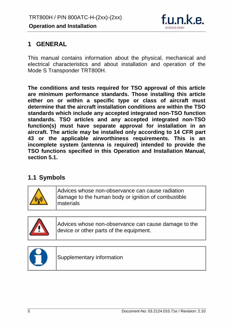
TRT800H PN 800ATC-H-(2xx)-(2xx)
Operation and Installation
6 Document-No 03212401071e Revision 210
12 Abbreviations
Abb Meaning Explanation
FID Flight ID Flight plan number or if not assigned registration number of aircraft
SPI Special Position Identification
Activation on request by controllers bdquoSquawk Identldquo transmits SPI Pulse for 18 seconds which highlights the respective traffic item on the controllers radar screen
AA Aircraft Address assigned ICAO 24-bit address
AC Aircraft Category Defines aircraft type according to specific categories
RI Reply Information Maximum airspeed
13 Customer Support
In order to facilitate a rapid handling of return shipments please follow the instructions of the input guide bdquoReshipment RMAldquo provided at the Service-Area within the funke AVIONICS GmbH web portal wwwfunkeavionicsde
Any suggestions for improvement of our manuals are welcome Contact servicefunkeavionicsde
Information on software updates is available at funke AVIONICS GmbH
TRT800H PN 800ATC-H-(2xx)-(2xx)
Operation and Installation
7 Document-No 03212401071e Revision 210
14 Features
In order to operate the Mode S transponder it is necessary to request an ICAO 24-bit Aircraft Address at the responsible national aviation authorities The received Code is assigned to the specific transponderaircraft and must be configured within the transponder The 24-bit address is stored in an external memory which allows the transponder being exchanged without requiring any further configuration (for detailed information refer to sections 431 and 454)
Class 1 Level 2es non-diversity Mode S transponder for ground based interrogations at 1030 MHz and response at 1090 MHz
Replies to (Secondary) Radar Interrogations
o Mode A replies with a Squawk (one of 4096 possible Codes eg flight plan number Squawk assigned by a controller or the VFR Squawk 7000)
o Mode C replies including encoded flight level
o Mode S replies including aircraft address and flight level
o Extended Squitter containing additional information on position and velocity
IDENT capability for activating the Special Position Identificationldquo-Pulse (SPI) for 18 seconds which is requested by the Controller bdquoSquawk Identldquo
Maximum flight level 35 000 ft maximum airspeed 250 kt
Display information contains Squawk code mode of operation and pressure altitude
Temperature compensated high precision piezo-resistive pressure sensor
RS-232 IO data port enabling connection with certain GPS-Receivers in order to support ADS-B Out
8 storable entries for AA-AC-Code FID Ground-Switch RI-Code and GPS-Interface-setting (stored in external memory TRT800EMxx)
Remote control unit interface
TRT800H PN 800ATC-H-(2xx)-(2xx)
Operation and Installation
8 Document-No 03212401071e Revision 210
15 Deviations and Important Notes
The following deviations have been granted by the FAA
The device is certified to FAA TSO-C112c in lieu of FAA TSO-C112d
Environmental Qualification Testing was performed according to RTCADO-160D in lieu of RTCADO-160F
The Software of this device was developed according to RTCA DO-178B Design Assurance Level D
The ADS-B function of this device has not been evaluated during the FAA TSO certification process other than to ensure non-interference Due to the SW assurance of DAL D the ADS-B function cannot be used in the US National Airspace
Connecting a GPS source will not comply to FAA certification requirements with regard to ADS-B
This device contains an altitude measuring device that has not been evaluated during the FAA TSO certification process other than to ensure non-interference
This feature must be evaluated for intended function during FAA installation approval
Compliance to RTCA DO-181D was verified by testing against EUROCAE ED-73C The two standards are technically identical with regard to the TRT800H
TRT800H PN 800ATC-H-(2xx)-(2xx)
Operation and Installation
9 Document-No 03212401071e Revision 210
2 OPERATION
21 Controls
ON OFF
bdquoSquawk Identldquo
Activate deactivate VFR
Change Active Standby
Squawk
Select Operation Mode
Cursor adjustment
Rotary Knob for adjusting values at the cursor position
active
Operation
Mode
standby Standby Squawk
Active Squawk
TRT800H PN 800ATC-H-(2xx)-(2xx)
Operation and Installation
10 Document-No 03212401071e Revision 210
IO ONOFF
Switch ON press button for approx 05 s
Switch OFFpress button for approx 3 s
VFR VFR
activatedeactivate VFR Squawk (press shortly)
store active Squawk as VFRVFRW-Squawk (press button 3 s rarr28)
CHANGE
change between active and standby-Squawk
works as cursor back button (opposite function of the cursor button) during entering values and also for navigating backwards through the configuration menu (rarr454)
ID IDENT
bdquoSquawk Identldquo sends Ident marking (SPI) for 18 s (rarr 29)
Enter Flight-ID (FID) setup (in standby mode press button for approx 5s)
MODE MODE Select transponder operational mode (rarr 26)
CURSOR Set position of Cursor
Rotary Knob
AdjustEnter values at current cursor position select options set standby Squawk (rarr 27)
TRT800H PN 800ATC-H-(2xx)-(2xx)
Operation and Installation
11 Document-No 03212401071e Revision 210
22 Switch ONOFF
Switch ON press IO for 05 s
Switch OFF press IO for 3 s
221 Display information after power up
After turning-on the display appears as follows (example)
If more than one configuration record is programmed the record selection menu appears (example)
Select the desired record (rotary switch) and confirm with MODE
If no external memory is connected or no 24bit address is defined the message ldquoCRADLE OFFrdquo appears In this case the device is working as ldquoMode AC onlyrdquo transponder
The transponder starts in STBY mode
2000 FL 030
STBY 7000
Cradle OFF
24D5F2 lt 000000 BE2343 000000 D4B3AA 000000 000000 000000
TRT800H V53
FPGA-Vers 102
Device Name
Software Version
Firmware Version
TRT800H PN 800ATC-H-(2xx)-(2xx)
Operation and Installation
12 Document-No 03212401071e Revision 210
23 Display - Indications
Value Meaning Remarks
7000 active Squawk
2000 Standby Squawk Could be changed with active Squawk by pressing
FL 030
FLerr
Flight Level
Invalid altitude measuring
Flight Level (in 100 ft steps)
Beyond -1000 35 000 ft C Mode gets inactive
ACS Operational Mode (STBY A-S ACS AC A)
Modes see section 26
IDT transmits Ident-Marking (SPI) ID (bdquoSquawk Identldquo) has been pressed ndash active for 18 s
Transponder replies
on Mode-S Mode-A or Mode-C interrogations
No indication on ADSB and squitter transmission
| Transponder is locked by a ground station and will be directly addressed
Lock Information (indicated below the diamond)
F
G
in-flight
on-ground
Ground-Switch-Info
(if installedavailable)
ACS
7000
TM
PLLTRX DC | BATDIM
IDT FL 030
STBY 2000 F
Passive Squawk
Active Squawk
Test mode indicatior
GND switch status
Operational Mode Standby
SPI indicator
Error indications
Reply indication
Lock out indication
Flight level
Backlight setup
Low battery ind
Operational Mode Active
TRT800H PN 800ATC-H-(2xx)-(2xx)
Operation and Installation
13 Document-No 03212401071e Revision 210
Value Meaning Remarks
Error indicators
PLL PLL Error Internal Error
TRX Transmit Failure Check antenna and wiring
DC Low internal voltage Internal error
FPG FPGA-Failure Internal error
BAT Battery Power too low maybe batterygenerator fault
24 Display-Brightness
In active mode (not standby) press for 2 s
Display indicates ldquoDIMrdquo Adjust brightness (DIM) with rotary knob
Return to normal operation press or wait 5 s
25 Flight-ID (FID)
The FID is an identifier required for Mode S Operation During future application of flight plans a FID could be assigned on a per flight basis If no FID is assigned (todayrsquos normal case) the registration marking of the aircraft should be used as FID The FID should not contain dashes or blanks The FID must not be confused with the 24-bit Aircraft Address
251 Display Flight-ID
Press MODE (repeatedly) until bdquoSTBYldquo appears
Press and hold ID while a counter is shown beside the active squawk During a few seconds Flight Identification is displayed
FID 02
A B C D E F G H
-
TRT800H PN 800ATC-H-(2xx)-(2xx)
Operation and Installation
14 Document-No 03212401071e Revision 210
252 Configure Flight-ID
Press MODE (repeatedly) until bdquoSTBYldquo appears
Press and hold ID while a counter is shown beside the active squawk Release ID when ldquoCHANGE FIDrdquo is displayed
Enter Flight-Id with cursor button and rotary knob
Press MODE to save and return to STBY
Please refer to section 454 for configuration of the 24-bit Address (AA) and Aircraft Category (AC)
26 Transponder Mode selection
Press MODE (repeatedly) to select from following Modes
STBY bdquoStandbyldquo Transponder does not respond to any interrogation Squitter and ADS-B output is not active
A C S bdquoMode A+C+Sldquo Standard condition transponder responds to mode A C and S interrogations
A ndash S bdquoMode A+S no Cldquo Altitude is not transmitted (neither on C nor on S requests) All other Mode-S data as well as Mode-A replies are transmitted
Enter FID left-aligned without any blanks or dashes () eg 12345621DEFAV for the marking D-EFAV The last remaining digits shall be filled with blanks
CHANGE FID
_ _ _ _ _ _ _ _ A B C D E F G H
- exit
TRT800H PN 800ATC-H-(2xx)-(2xx)
Operation and Installation
15 Document-No 03212401071e Revision 210
If no 24-bit address (AA) was defined or entered as ldquo000000ldquo the transponder operates as a Mode AC transponder in that case the following Modes are possible apart from Standby
A C ndash bdquoMode A+Cldquo Transponder replies only on Mode A and Mode-C interrogations
A ndash ndash bdquoMode Aldquo Transponder replies only on Mode A interrogations
In STBY (Standby) mode all transponder transmissions are disabled completely Therefore the transponder is not visible in this mode to air traffic control or the anti-collision systems onboard other aircrafts
Never use the STBY mode in flight unless you are requested to do so by air traffic control Always remember to put the transponder in active mode prior to take off
27 Squawk-Setting
The active Squawk is displayed in the upper line while the standby Squawk is presented at the lower line
Setting the Standby Squawk
Press to set the cursor (bdquo^ldquo) turn rotary knob to set numbers of the standby Squawk
Press to activate the Standby Squawk (this moves the current active Squawk into Standby)
28 VFR ndash Squawk
The transponder features a user-defined squawk code for VFR-flight (factory setting 7000)
Activate VFR-Squawk
Press VFR (bdquoVFRldquo is indicated) now the active Squawk is moved into Standby but not visible because the indication of the Standby Squawk is overlapped by bdquoVFRldquo
TRT800H PN 800ATC-H-(2xx)-(2xx)
Operation and Installation
16 Document-No 03212401071e Revision 210
Display Standby Squawk
Press VFR or or use the rotary knob (the VFR-Squawk remains active)
Example
VFR VFR
Now the Standby Squawk can be adjusted by using the rotary knob and activated with
In order to store the current active Squawk as new VFR-Squawk (replacing the factory setting 7000) Press and hold VFR until an bdquoSldquo is indicated (approx 3 s) after releasing the button bdquoVFRldquo is shown
29 ID ndash Special Position Identification (SPI) ldquoSquawk Identrdquo
Press ID to activate transmission of the special position identification pulse with every reply within 18 seconds ldquoIDTrdquo appears on the display
By pressing ID a special position identification pulse (SPI) is transmitted with every reply within 18 seconds which causes an accented marking on the Controllerrsquos screen The bdquoSpecial Position Identificationldquo has to be activated after the bdquoSquawk Identldquo request of the Controller
210 Error-Codes
Please refer to 23 Display - Indications for possible displayed errors
7000
FL 030
STBY 4700
7000
FL 030
STBY VFR
4700
FL 030
STBY 5600
TRT800H PN 800ATC-H-(2xx)-(2xx)
Operation and Installation
17 Document-No 03212401071e Revision 210
3 INSTALLATION
31 Notes
The following suggestions should be considered before installing
The assigned installation company will supply wiring For diagrams refer to 37 Wiring
Transponder External Memory all cables and antennas shall be installed according to bdquoFAA AC-14313-2A Acceptable Methods Techniques and Practices ndash Aircraft Alterationsldquo and the appropriate manufacturerrsquos instructions
32 Telecommunication data
Depending on your national telecommunications legislation the following data may be required when applying for the aircraft radio station license
Manufacturer funke AVIONICS GmbH
Type Designation TRT800H
EASA Number EASA21O269
Transmitter Power Output
126 W
Frequency 1090 MHz
Emission Designator 12M0M1D
33 Scope of Delivery
Item namenumber Description
TRT800H Transponder TRT800H
TRT800EMSS External Memory (Aircraft-Address-Adaptor with wiring)
M4X8ZSW (3 pieces) screw for panels up to 5 mm thickness
56S101A4 TNC antenna connector
03212401071e Manual bdquoOperation and Installationldquo
EASA Form 1
TRT800H PN 800ATC-H-(2xx)-(2xx)
Operation and Installation
18 Document-No 03212401071e Revision 210
34 Unpacking and Inspecting of the Equipment
Carefully unpack the equipment and inspect for transport damages If a damage claim has to be filed save the shipping container and all packing materials as evidence to your claim
35 Mounting
In cooperation with a maintenance shop location and kind of the installation are specified The maintenance shop can supply all cables Suitable sets of cables are available from funke AVIONICS GmbH
Select a position away from heat sources Provide space for adequate convection cooling
Leave sufficient space for the installation of cables and connectors
Avoid sharp bends and wiring close to control cables
Leave sufficient lead length for inspection or repair of the wiring of the connector (containing the memory) so that when the mounting hardware for the rear connectors is removed the assembly may be pulled forward several inches
Bend the harness at the rear connectors to inhibit water droplets (formed due to condensation) from collecting in the connector
For mounting detailsdrawing refer to chapter 3122 Mounting Advices
For storage or reshipment the original packaging should be used
TRT800H PN 800ATC-H-(2xx)-(2xx)
Operation and Installation
19 Document-No 03212401071e Revision 210
36 Equipment Connections
361 Electrical Connections
One 15 pin D-SUB miniature connector includes all electrical connections except for the antenna Use only an External Memory Adapter TRT800EMxx as this is part of the certification and includes a memory device in which the ICAO 24-bit Aircraft Address is stored
3611 Mutual Suppression
Other equipment on board (e g DME) may transmit in the same frequency band as the transponder
If such a device is installed a suppression wiring shall be installed in order to protect the receiving parts of the different devices from in-band transmissions
Mutual suppression is a synchronous pulse that is sent to the other equipment to suppress transmission of a competing transmitter for the duration of the pulse train transmission The transponder transmission may be suppressed by an external source and vice versa
To activate mutual suppression connect the SUPP_IO signal to the according signals of the other equipment
3612 Ground Switch
If an external Ground-Switch is connected to the transponder and activated in the setup the transponder can detect if the aircraft is airborne or on the ground This allows the transponder to automatically activate the Ground mode whenever the aircraft is on ground
In order to activate this feature the input bdquoFLY-GNDldquo must be connected to an external switch which connects the input pin with bdquoGNDldquo when the gear is weighted or remains open in the other case
This feature must additionally be activated in the Setup For details on configuration please refer to section 454
The (+UB)-wire has to protected by circuit breaker (2 Amp)
TRT800H PN 800ATC-H-(2xx)-(2xx)
Operation and Installation
20 Document-No 03212401071e Revision 210
3613 Auto-On
The Auto-On input allows to define how the transponder will behave when power is supplied to it
If the aircraft is equipped with a dedicated avionics master switch that switches the power supply to the transponder the pin Auto-On must be wired together with the UB+ pin to the avionic master switch The onoff button on the transponder is without function in that case The transponder will start automatically whenever power is supplied
On aircraft without such an avionics master switch the pin Auto-On must be left unconnected In this case the transponder must be switched on and off via the transponders onoff button on the front panel
362 Static Air Port
Install a silicon soft tube fitting the 5 mm static air hose at the backside of the transponder and secure plumbing with appropriate clamps
37 Wiring
371 Conductor Cross Section
Power Supply (Power GND) AWG20 (062 mmsup2)
Signals AWG22 (038 mmsup2)
The conductors must be approved for aircraft use
TRT800H PN 800ATC-H-(2xx)-(2xx)
Operation and Installation
21 Document-No 03212401071e Revision 210
372 Pin Assignment
The transponder may only be operated together with an external memory address adaptor TRT800EMxx
Pin Signal Remarks Adaptor
Typ(4)
TRT800
EM
Adaptor
Typ(4)
TRT800
EMSS
Adaptor Typ
TRT800
EMRS
1 GND -
2 Remote control(1) Input
3 EEPROM Signal TRT800EMxx internal
4 EEPROM Signal TRT800EMxx internal
5 TX RS-232 Serial Output
6 Switched +UB(1) Output
7 Remote control(1) Output
8 +UB power supply Input
9 GND -
10 EEPROM VCC TRT800EMxx internal
11 EEPROM GND TRT800EMxx internal
12 RX RS-232 Serial Input
13 Suppression Input Output
14 Auto-On(2) Input(2)
15 Fly-GND Switch(3) Input(3)
= in the plug and get out = in the plug and not get out ∕ = internal connection to the device
(1) SWITCHED +UB OUT Interface Remote control
May only be used for compatible funke AVIONICS devices Do not connect pins if interface is not used
(2) Auto-On Connect to +UB override front panel onoff button Leave unconnected to use front panel onoff button
(3) Ground Switch
FLY-GND
If an external Ground Switch is connected it must connect this pin to GND to indicate the on-ground condition Leave open otherwise
(4) Adaptors TRT800EM amp TRT800EMSS
Adaptor version does not provide full interface capability (see table for details)
TRT800H PN 800ATC-H-(2xx)-(2xx)
Operation and Installation
22 Document-No 03212401071e Revision 210
373 Cable plan External Memory EM800
3731 Cable plan TRT800EMRS (older version with interface remote)
to SN 90932013
DSUB 15pol
TRT800HTRT800A
lt PIN-5 gt
lt PIN-12gt
lt PIN-15gt
lt PIN-13gt
lt PIN-7 gt
lt PIN-2 gt
lt PIN-6 gt
lt PIN-1 gt
lt PIN-9 gt
lt PIN-8 gt
lt PIN-14gt
TXD
RXD
FLY_GND
SUPP_IO
GND
open
cable
ends
Remote Binder
Connector
female
white
black
yellow
red
shield
blue
red
brown
GND
+UB
AUTO-ON(2)(3)
black
white
red
yellow
shield
Binder Connector female
(solder side)
1 2 3 4 5 6 7 8
9 10 11 12 13 14 15
D-SUB Connector female
(solder side)
open
cable
ends
1 New interface available
-at TRT800H starting from SN 30430109 with SW V53
-at TRT800A starting with SW V53 2 New TRT800H interface starting from HW 60 3 port function not available at TRT800A
3
4 2
5 1
RMT-LIGHT
GND
RMT-TXD
RMT-SW+UB
RMT-RXD
RMT-TXD(1)
RMT-RXD(1)
RMT-SW+UB(2)(3)
RMT-LIGHT(2)
GND(1)
TRT800H PN 800ATC-H-(2xx)-(2xx)
Operation and Installation
23 Document-No 03212401071e Revision 210
3732 Cable plan TRT800EMRS (newer version with interface remote)
from SN 90932114
DSUB 15pol
TRT800HTRT800A
lt PIN-5 gt
lt PIN-12gt
lt PIN-15gt
lt PIN-13gt
lt PIN-7 gt
lt PIN-2 gt
lt PIN-6 gt
lt PIN-1 gt
lt PIN-9 gt
lt PIN-8 gt
lt PIN-14gt
TXD
RXD
FLY_GND
SUPP_IO
GND
open
cable
ends
Remote Binder
Connector
female
white
brown
yellow
green
shield
blue
red
brown
GND
+UB
AUTO-ON(2)(3)
brown
white
green
yellow
shield
Binder Connector female
(solder side)
1 2 3 4 5 6 7 8
9 10 11 12 13 14 15
D-SUB Connector female
(solder side)
open
cable
ends
1 New interface available
-at TRT800H starting from SN 30430109 with SW V53
-at TRT800A starting with SW V53 2 New TRT800H interface starting from HW 60 3 port function not available at TRT800A
3
4 2
5 1
RMT-LIGHT
GND
RMT-TXD
RMT-SW+UB
RMT-RXD
RMT-TXD(1)
RMT-RXD(1)
RMT-SW+UB(2)(3)
RMT-LIGHT(2)
GND(1)
TRT800H PN 800ATC-H-(2xx)-(2xx)
Operation and Installation
24 Document-No 03212401071e Revision 210
3733 Cable plan TRT800EMSS (newer version without interface remote)
from SN 91032115
The External ndash Memory ndash Address - Adapter TRT800EMxx contains electronic parts and must not be opened Opening or modifying the connector leads to the loss of airworthiness certification
DSUB 15pol
TRT800HTRT800A
lt PIN-5 gt
lt PIN-12gt
lt PIN-15gt
lt PIN-13gt
lt PIN-1 gt
lt PIN-9 gt
lt PIN-8 gt
lt PIN-14gt
TXD
RXD
FLY_GND
SUPP_IO
GND
open
cable
ends
white
brown
yellow
green
shield
blue
red
brown
GND
+UB
AUTO-ON(2)(3)
open
cable
ends
2 New TRT800H interface starting from HW 60 3 port function not available at TRT800A
1 2 3 4 5 6 7 8
9 10 11 12 13 14 15
D-SUB Connector female
(solder side)
TRT800H PN 800ATC-H-(2xx)-(2xx)
Operation and Installation
25 Document-No 03212401071e Revision 210
38 Antenna
381 Antenna Selection
Recommended antennas see section 311 Accessories
Choose an antenna type compatible with the vehicle and the mounting location
Specified features depend on proper installation of the antenna
The radiation pattern needs to be verified considering aircraft type and mounting location
The electrical interference between the antenna and any other equipment must be taken into account in such a way that no reduction of the performance of any other system will occur
Install only certified antennas
382 Installation Recommendation
Take note of the antenna manufacturerrsquos instructions
The usually deployed Dipole- or Blade antennas necessarily require a high frequency capable solid metal ground plane at the antenna base
For installation in composite aircrafts ground planes are to be added The ground plane should be as large as possible but in any case not smaller than 10 cm x 10 cm If in doubt please contact the aircraft manufacturer
Keep away three feet from any other antenna
Pursue mounting in vertical position under the belly in flight direction
383 Antenna Wiring
Suitable antenna cables see section 311 Accessories
Keep wiring as short as possible
The smallest cable bend radius is 10cm Avoid sharp bends
Keep away from an ADF antenna cable at least 12 inches
Electrical connections to the antenna shall be protected against moisture to avoid loss of efficiency
TRT800H PN 800ATC-H-(2xx)-(2xx)
Operation and Installation
26 Document-No 03212401071e Revision 210
39 Post-Installation Check
All steering and control functions of the aircraft are to be examined in order to exclude disturbances by the wiring
The most important factor in the transponder configuration is the setting of the ICAO address (see section 454)
Attenuation from antenna to transponder at 1090 MHz must not exceed 15 dB
A certified maintenance shop must verify proper operation of the transponder by testing in accordance with Appendix F of ldquo14 CFR Part 43 ndash ATC Transponder Tests and Inspectionsrdquo
TRT800H PN 800ATC-H-(2xx)-(2xx)
Operation and Installation
27 Document-No 03212401071e Revision 210
310 Starting Up
Turn the transponder on with IO After start-up the following screens appear
311 Accessories
Part Number Description
TRKABEL1 Antenna cable 10 m (32 ft) TNC BNC
TRKABEL2 Antenna cable 25 m (82 ft) TNC BNC
TRKABEL3 Antenna cable 40 m (132 ft) TNC BNC
TRKABEL4 Antenna cable 65 m (213 ft) TNC BNC
TRT800EMRS External-Memory (Aircraft-Address-Adaptor) Connection cable with interface TRT-Remote control
CI-105 TransponderDME Antenna TSO C66b C74c
CI105 Comant Industries Inc
Height 325rdquo Weight 90 g (02 lbs)
AV22 Transponder Rod antenna TSO C74c
AV-22 R A Miller Industries
The TRT800H starts in standby mode (indicated with STBY) In order to change into operational mode (indicated with ACS) press MODE If ground switch is connected and status ldquoin flightrdquo is selected TRT800H starts in active mode
Very important is the correct configuration of the 24bit Aircraft-Address (see 454 General Setup)
TRT800H V53
FPGA-Vers 102
2000 FL 030
STBY 7000
TRT800H PN 800ATC-H-(2xx)-(2xx)
Operation and Installation
28 Document-No 03212401071e Revision 210
312 Drawings
3121 Dimensions
20mm15 mm
170 mm
TRT800TRT800H
65 mm
65
mm
Oslash 57 mm
Static Air
Antenna
PowerRS232
3122 Mounting Advices
Connections Area
8
0 m
m
Panel Cut-out
470 mm
470
mm
575 mm
4 x Oslash 4 mm
Oslash
Connector (plug) has to be clamped with both spring locks
No screws may be turned in more than max 15mm into the device ndash even if no hard limit is noticeable
Fixing clips (spring) left right
TRT800H PN 800ATC-H-(2xx)-(2xx)
Operation and Installation
29 Document-No 03212401071e Revision 210
4 TRANSPONDER SETTINGS
41 Overview
The TRT800H is capable of storing the following information
ICAO 24-Bit Aircraft-Address (AA)
Aircraft Category (AC)
Flight Identification (FID)
Ground-Switch (YesNo)
Speed Category (RI)
RS232 Interface Configuration
All of these data are configurable in the Setup and are stored in the external memory module integrated within the housing of the D-Sub connector (included in the delivery)
The cable with this connector shall remain in the aircraft even if the unit is removed to ensure that the ICAO 24bit aircraft address is fixed to the aircraft
Additionally the following usertransponder related settings are stored transponder internally
Active Squawk
Passive Squawk
VFR Squawk
Altitude offset
Display brightness
42 Display Configuration Summary
Transponder provides the opportunity to show summary of complete current settings To access configuration summary pages push and hold
ID in Standby mode Release ID if ldquoSHOW SETUPrdquo is displayed The summary is subdivided into the following pages
TRT800H PN 800ATC-H-(2xx)-(2xx)
Operation and Installation
30 Document-No 03212401071e Revision 210
Page 1
Aircraft Address
Aircraft Category
Flight Identification
MODE
Page 2 Speed Category
Ground Switch option
Remote Header option
MODE
Page 3 RS-232 Settings
Protocol baud rate position (if available)1
MODE
Page 4 Altitude correction settings
(part 1)
MODE
Page 5 Altitude correction settings
(part 2)
Note 1 Position data will only be displayed if
a GPS protocol is set as interface protocol (NMEA FREEFLIGHT AR-NAV)
18000 ft 0ft 25000 ft + 100ft 35000 ft - 50ft
exit
ALTITUDE CORRECTION 2000 ft 0ft 10000 ft + 100ft next
RS-232 NMEA Baud 4800 Pos 481 99 next
Speed Cat 8 Ground Sw YES Remote Hd NO next
AA F E 1 2 3 4 AC 1 9 FID 4 4 E 1 2 3 next
TRT800H PN 800ATC-H-(2xx)-(2xx)
Operation and Installation
31 Document-No 03212401071e Revision 210
GPS receiver is connected and transmits data (if not ldquoPos no datardquo is displayed)
a valid position is transmitted (if not ldquoPos wrong datardquo is displayed)
While configuration summary page is displayed no new position data will be processed
43 General settings
431 ICAO 24-Bit Aircraft Address (AA)
Ask your national aviation authority (e g in Germany LBA Referat B5 Department ldquoVerkehrszulassungrdquo) how to obtain the AA In the case of aerial sports equipment the contact point would be the respective associations Only the assigned AA has to be used and must not be modified at any time because a duplicate address would jeopardize the data surveillance and integrity figures of Mode S
If no AA is stored after power on the display shows ldquoCRADLE OFFrdquo and the transponder operates in Mode AC
(Configuration of the AA see section 454)
432 Aircraft Category (AC)
Code Description Code Description
11 Emergency Vehicle 1C Ultra-Light Paraglider
12 Service Vehicle 1E Drone
19 Glider 21 Aircraft (D-Exxx) lt 15500 lbs Motor Glider (D-Kxxx)
1A Balloon amp Airship 22 Aircraft ge 15500 lbslt 75000 lbs
1B Paratrooper 27 Rotorcraft
Only one of the Codes mentioned in the table above must be used
Setuprarr454
Setuprarr454
TRT800H PN 800ATC-H-(2xx)-(2xx)
Operation and Installation
32 Document-No 03212401071e Revision 210
433 Flight-ID (FID)
Per ICAO regulation Mode-S data must contain a valid flight identification (FID) to ensure that the correlation between flight plan and radar data will work automatically
FID setting is required to correspond to the aircraft identification that has been specified at item 7 of the ICAO flight plan It contains seven characters at a maximum (left-aligned no additional zeros dashes or spacesblanks)
For an aircraft using a company call sign the Flight-ID mostly consists of the ICAO three-letter designator for the aircraft operator followed by an identification code eg KLM511 BAW213 JTR25
If no company call sign is used or no flight plan is filed the default FID to be set consists of the registration marking of the aircraft (eg DEABC) with no dashes spacesblanks or additional zeros even if they are included in the registration marking on the aircraft (tail number) While entering the FID into the transponder the last remaining digits must be filled with blanks
The ICAO Flight Plan only specifies 7 characters for FID funke AVIONICS reserves 8 characters as stated in ED-73B for further expansion of the flight plan
The user shall only program 7 characters for FID
Setuprarr454
TRT800H PN 800ATC-H-(2xx)-(2xx)
Operation and Installation
33 Document-No 03212401071e Revision 210
434 Reply Information - Speed Category (RI)
Besides AA AC and FID another important part of the Mode-S data is the Speed Category of the respective aircraft This speed category shall be configured in the setup and must contain one of the following codes
Code Description
08 No maximum airspeed data available
09 Maximum airspeed le 75 kt
10 75 kt gt maximum airspeed le 150 kt
11 150 kt gt maximum airspeed le 300 kt
12 300 kt gt maximum airspeed le 600 kt
13 600 kt gt maximum airspeed le 1200 kt
14 Maximum airspeed gt 1200 kt
15 Not assigned
44 Optional settings
441 Option Ground-Switch
If a ground switch is connected (and enabled in setup) the transponder is able to determine on-ground and in-flight state On-ground state is activated automatically once the gear touches the ground On-ground state is indicated on display by symbol G (apart from lsquoFrsquo for In-flight-state)
In On-ground-state the transponder will reply differently to certain addressed interrogations Also the transmission rate of some periodically sent data (squitters ADS-B) is reduced This allows ATC to distinguish between airborne aircraft and those on the ground and it reduces the Mode S channel load
For small aircraft authorities normally do not require such a ground switch In this case the transponder will use the same data formats on the ground as in the airborne state
Setuprarr454 Wiringrarr373
Setuprarr454
TRT800H PN 800ATC-H-(2xx)-(2xx)
Operation and Installation
34 Document-No 03212401071e Revision 210
442 Option Remote Header
The transponder provides a TRT800RT remote control interface If a remote header TRT800RT is connected transponder can be remote controlled via this interface Remote interface provides control of all standard user inputs available during standard operational mode For more information see TRT800RT manual Remote control interface de-activation is setup configurable Remote control interface must only be connected to TRT800RT
443 Serial Interface (RS232)
Using serial interface a GPS receiver can be connected to broadcast own position via ADS-B Out position message Position could be received by other appropriately equipped aircrafts and processed for collision avoidance ADS-B Out functionality
The ADS-B function of this device has not been evaluated during the FAA TSO certification process other than to ensure non-interference Due to the SW assurance of DAL D the ADS-B function cannot be used in the US National Airspace Connecting a GPS source will not comply to FAA certification requirements with regard to ADS-B
Supported formatsprotocols are
Option Description Baud rate
FREEFLIGHT GPSWAAS Sensor 1201
NexNav NNL 3101
19200
AR-NAV Bendix King
KLN 89B KLN 94 ldquoStandard RS232 Sentencerdquo
KMD 150 ldquoSentence Type 1rdquo
Garmin 400 Series ldquoSentence Type 1rdquo (with and without altitude data)
9600
NMEA NMEA-Format data format RMC is expected
4800
Setuprarr454 Wiringrarr373
Setuprarr454 Wiringrarr373
TRT800H PN 800ATC-H-(2xx)-(2xx)
Operation and Installation
35 Document-No 03212401071e Revision 210
Option Description Baud rate
FAVISIA Glass Cockpit support
FAVISIA Data format to be processed in FAVISIA avionics suite
-
FAVISIA+GPS Data format to be processed in FAVISIA avionics suite (output) and additional processing of incoming NMEA GPS-Receiver position data to support the ADS-B Out functionality
4800
Other
Comm-AB-support
Data format for special purpose An additional data link processor allows COMM-AB operation and processing of the position information of a flight management system simultaneously
38400
Disabled No communication via RS232 interface -
444 Altitude CorrectionOffset
The TRT800H has an integrated temperature compensated high-precision pressure sensor This sensor is factory-calibrated so that it will yield accurate flight level (uncorrected pressure altitude) within the entire altitude range
However due to differences in calibration of the TRT800H pressure sensor and the altimeter in the cockpit it may become necessary to adjust the TRT800H pressure readings so that the value indicated and transmitted by the TRT800H corresponds to the indication of the primary altimeter seen by the pilot within 125 feet (as specified in ETSO C88aSAE AS 8003)
Setting for all described GPS-systems
1 2 position messages per 2 sec
Setuprarr455
TRT800H PN 800ATC-H-(2xx)-(2xx)
Operation and Installation
36 Document-No 03212401071e Revision 210
The check for correspondence between the primary altimeter and the TRT800H is usually performed every 24 months as part of the aircrafts altimeter checks
Altitude correction is based on setup configurable offset values at five interpolation points ( 2000 8000 18000 25000 and 35000 ft)The offset value itself is limited to a range from -100 to + 100ft at each point (10ft steps)
45 Setup Procedure
Programming of the ICAOA 24-bit Aircraft Address and of the Aircraft Category shall be executed by qualified personnel only
A wrong Aircraft Address or Flight ID may cause serious problems ATC or with ACASTCAS systems
Pilot and owner are responsible for correctly set transponder data
451 Setup Menu Control
In order to access the functions described in the following paragraphs push and hold ID in Standby mode Release ID if desired counter value menu name is displayed to enter the menu The following menu entries are selectable
Count Displayed Name Function
03 FID FID is displayed
48 CHANGE FID Enter FID setup page
913 SHOW SETUP Enter setup summary listed on different pages (no changes possible)
2528 ENTER SETUP Enter transponder general configuration pages
3134 ALTITUDE CORRECTION
Enter altitude correction menu
TRT800H PN 800ATC-H-(2xx)-(2xx)
Operation and Installation
37 Document-No 03212401071e Revision 210
452 Transponder configurationrecord structure
Aircraft related parts of transponder configuration are stored in one out of eight possible records (record=presetting) Each record contains the following information
Aircraft Address (AA 24bit)
Aircraft category (AC)
Flight identification (FID 6-8 numbersletters)
RS-232 Interface setting (eg GPS protocol)
Ground-Switch setting (Installed YesNo)
Speed category (RI) of the respective aircraft
Remote Header setting (Installed YesNo)
User related settings (eg squawk codes display brightness) are stored once in one global record (transponder internally)
453 Transponder configurationrecord handling
At least one record is stored in external memory Up to 8 records can be additional be applied during setup process
If more than one record is applied the active record must be selected out of a list (determined by FID) during start-up of the transponder
Previously applied records can be deleted again by filling FID with zerorsquos only
454 General Setup
Any menu item can be passed by MODE If no changes are made the original settings will remain stored Modification of one menu item does not impact the others No entries will be deleted
TRT800H PN 800ATC-H-(2xx)-(2xx)
Operation and Installation
38 Document-No 03212401071e Revision 210
Step Display (Example)
1 Start-up Transponder
2 Ensure the transponder-mode is bdquoSTBYldquo If necessary change the mode by pressing MODE
3 Press ID A counter is shown at the upper-right corner Hold ID till ldquoENTER SETUPrdquo is displayed
4 After release of ID the first setup menu is displayed
5 helliphellipselect position (^)
rotary knobchange value
MODE
6 With the rotary knob you can select bdquoyesldquo if a Ground Switch is installed if not select ldquonordquo and proceed with step 7
MODE
Record 1
GND Switch YesNo
next
AA EF123456
AC 18
FID ^BCDEFG
next
AA EF123456
AC 18
FID ABCDEFG
next
ENTER SETUP 26
2000 FL 030
STBY 7000
TRT800H PN 800ATC-H-(2xx)-(2xx)
Operation and Installation
39 Document-No 03212401071e Revision 210
Step Display (Example)
7 At this stage the respective speed category shall be selected by using the rotary knob
MODE
8 At this stage a GPS receiver for ADS-B Out can be selected (Selectable by rotary knob)
MODE
9 At this stage remote interface for communication between TRT800H and remote header can be activated (Selectable by rotary knob)
Remote interface must only be activated if a remote header is connected
MODE
10 With ID further Records can now be created and configured as described in the aforementioned steps At start-up of the transponder one of the defined records with all associated configurations need to be selected
MODE
Records ID=Edit Records
EXIT
Record 1
REMOTE Header YesNo
next
Record 1
GPSINTEXT NMEA
next
Record 1
Speed Cat 08-15
next
TRT800H PN 800ATC-H-(2xx)-(2xx)
Operation and Installation
40 Document-No 03212401071e Revision 210
Step Display (Example)
11 You have now left the configuration mode and are back in normal operation
12 Switch off the transponder
13 Switch on the transponder Your ICAO 24-Bit Aircraft Address is now stored
TRT800H V53
FPGA-Vers 102
2000 FL 030
STBY 7000
TRT800H PN 800ATC-H-(2xx)-(2xx)
Operation and Installation
41 Document-No 03212401071e Revision 210
455 Altitude Correction Setup
Altitude correction setup shall be executed by qualified personnel only
Pilot and owner are responsible for correctly set altitude offset values
The usesetting of altitude correction values is only necessary in exceptional cases (see 444 for details)
Altitude correction is based on five interpolation points ( 2000 10000 18000 25000 and 35000 ft)The offset value at each interpolation point can be adjusted in a range from -100 to + 100ft at each point (10ft steps) Offset values set to zero at each interpolation point deactivates altitude correction (defaultfactory setting)
Step Display (Example)
1 Start-up Transponder
2 Ensure the transponder-mode is bdquoSTBYldquo If necessary change the mode by pressing MODE
3 Press ID A counter is shown at the upper-right corner Hold ID till ldquoALTITUDE OFFSETrdquo is displayed
ALTITUDE OFFSET 33
2000 FL 030
STBY 7000
Descriptionrarr444
TRT800H PN 800ATC-H-(2xx)-(2xx)
Operation and Installation
42 Document-No 03212401071e Revision 210
Step Display (Example)
4 After release of ID the first altitude level + corresponding offset value is displayed
5 Change offset value with rotary knob
MODE
6 (9) Repeat last step for another 4 altitude levels 10000ft 18000ft 25000ft 35000ft
MODE
10 You have now left the configuration mode and are back in normal operation
Switch off the transponder
11 Switch on the transponder New altitude offset values will now be used for altitude calculation
Altitude 10000 ft
Offset 0 ft
nextexit
Altitude 2000 ft
Offset 0 ft
next
TRT800H V53
FPGA-Vers 102
2000 FL 030
STBY 7000
Altitude 2000 ft
Offset 0 ft
next
TRT800H PN 800ATC-H-(2xx)-(2xx)
Operation and Installation
43 Document-No 03212401071e Revision 210
5 APPENDIX
51 Technical Data
Compliance CS-ETSO-2C112a
EASA21O269
FAA TSO-C112c
Applicable Documents CS-ETSO-2C112a
FAA TSO-C112c
EUROCAE ED-73C Class 1 Level 2es
RTCA DO-181D Class 1 Level 2es
EUROCAE ED-26
RTCA DO-160D
RTCA DO-178B Software-Level D
Temperature Ranges
Operation -20 degC to +55 degC for 30 min +70degC
Storage -55 degC to +85 degC
Altitude Range le 35 000 ft
Speed Range le 250 kt (TAS)
Shock 6 G Operation
20 G crash safety
Environmental Categories RTCA DO-160D EnvCat [C1Z]CAA[SM]XXXXXXZBAAA[TT]M[B3F3]XXA
Power Supply 138 VDC (10 VDC 16 VDC)
040 A 138 VDC (typ)
070 A 138 VDC (max)
10 W (max)
TRT800H PN 800ATC-H-(2xx)-(2xx)
Operation and Installation
44 Document-No 03212401071e Revision 210
Fuse External 2A-slow-blow fuse
Mounting Panel cut-out d=575 mm
Weight 06 kg (132 lbs)
Receiver Characteristics
Sensitivity
RF input power level resulting in a 90 reply rate
A MTL for ATCRBS and ATCRBSMode S All-Call interrogations -74 dBm plusmn3 dB
B MTL for Mode S interrogations -74 dBm plusmn 3 dB
Reply transmission frequency
1090 plusmn 1 MHz
RF Peak Power Output 21 dBW (126 W) at antenna base (with maximum cable attenuation of 15 dB)
Squitter (ADS-B) transmitted at random intervals uniformly distributed over the range from 08 to 12 seconds full self-verification of data and occurrence
Mode S Elementary Surveillance
ICAO 24-bit Aircraft Address (Hex-Code)
aircraft address as assigned by national aviation authority
FID Flight ID Flight Plan call sign or aircraft registration marking
Capability Report Reports the available data and means by which the transponder can report
Pressure Altitude Up to 35 000 ft in 25 ft increments
Flight Status in-flight on-ground
Mode S Enhanced Surveillance
Level 2es Comm-A Comm-B 56112-Bit-Messages
SI-capability
TRT800H PN 800ATC-H-(2xx)-(2xx)
Operation and Installation
45 Document-No 03212401071e Revision 210
52 Environmental Conditions
Characteristic DOndash160D Section Cat Condition
Temperature Altitude 40
C1
Low ground survival temperature
451 ndash 55degC
Low operating temperature 451 ndash 20degC
High ground survival Temperature
452 + 85degC
High Short-time Operating Temperature
452 + 70degC
High Operating Temperature 453 + 55degC
In-Flight Loss of Cooling 454 Z No auxiliary cooling required
Altitude 461 C1 35 000 ft
Temperature Variation 50 C 2degC change rate minimum per minute
Humidity 60 A
Shock 70 A
6 G operational shocks
20 G Crash Safety
Test Type R in all 6 directions
Vibration 80 S Vibration Curve M
Explosion Proofness 90 X No test required
Water Proofness 100 X No test required
Fluids Susceptibilities 110 X No test required
Sand and Dust 120 X No test required
Fungus Resistance 130 X No test required
Salt Spray 140 X No test required
Magnetic Effect 150 Z Less than 03 m
Power Input (DC) 160 B
Voltage Spike Conducted 170 A
Audio Frequency Conducted Susceptibility
180 A
TRT800H PN 800ATC-H-(2xx)-(2xx)
Operation and Installation
46 Document-No 03212401071e Revision 210
Characteristic DOndash160D Section Cat Condition
Induced Signal Susceptibility 190 A
Radio Frequency Susceptibility
200 TT
Emission of RF Energy 210 M
Lightning Induced Transient Susceptibility
220 B3F3
Lightning Direct Effects 230 X No test required
Icing 240 X No test required
Electrostatic Discharge (ESD) 250 A
53 DO-178B Open Problem Reports
There are no open problem reports for the software of this device
TRT800H PN 800ATC-H-(2xx)-(2xx)
Operation and Installation
47 Document-No 03212401071e Revision 210
Notes
f funke funke means ndash fabrication utilities network know-how engineering
funke AVIONICS GmbH Heinz-Strachowitz-Str 4
DE-86807 Buchloe Germany
phone +49-8241 80066 0
fax +49-8241 80066 99 E-mail
servicefunkeavionicsde wwwfunkeavionicsde
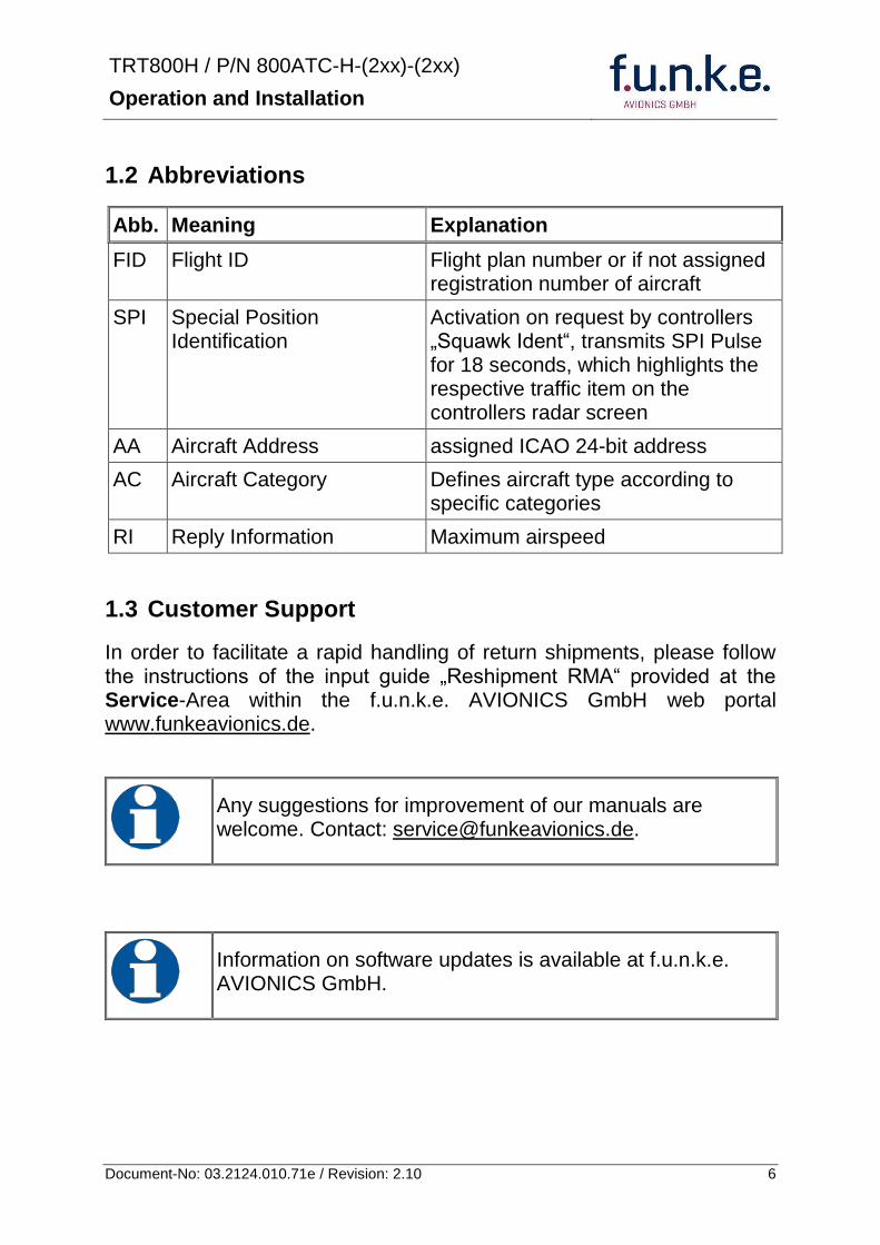
TRT800H PN 800ATC-H-(2xx)-(2xx)
Operation and Installation
7 Document-No 03212401071e Revision 210
14 Features
In order to operate the Mode S transponder it is necessary to request an ICAO 24-bit Aircraft Address at the responsible national aviation authorities The received Code is assigned to the specific transponderaircraft and must be configured within the transponder The 24-bit address is stored in an external memory which allows the transponder being exchanged without requiring any further configuration (for detailed information refer to sections 431 and 454)
Class 1 Level 2es non-diversity Mode S transponder for ground based interrogations at 1030 MHz and response at 1090 MHz
Replies to (Secondary) Radar Interrogations
o Mode A replies with a Squawk (one of 4096 possible Codes eg flight plan number Squawk assigned by a controller or the VFR Squawk 7000)
o Mode C replies including encoded flight level
o Mode S replies including aircraft address and flight level
o Extended Squitter containing additional information on position and velocity
IDENT capability for activating the Special Position Identificationldquo-Pulse (SPI) for 18 seconds which is requested by the Controller bdquoSquawk Identldquo
Maximum flight level 35 000 ft maximum airspeed 250 kt
Display information contains Squawk code mode of operation and pressure altitude
Temperature compensated high precision piezo-resistive pressure sensor
RS-232 IO data port enabling connection with certain GPS-Receivers in order to support ADS-B Out
8 storable entries for AA-AC-Code FID Ground-Switch RI-Code and GPS-Interface-setting (stored in external memory TRT800EMxx)
Remote control unit interface
TRT800H PN 800ATC-H-(2xx)-(2xx)
Operation and Installation
8 Document-No 03212401071e Revision 210
15 Deviations and Important Notes
The following deviations have been granted by the FAA
The device is certified to FAA TSO-C112c in lieu of FAA TSO-C112d
Environmental Qualification Testing was performed according to RTCADO-160D in lieu of RTCADO-160F
The Software of this device was developed according to RTCA DO-178B Design Assurance Level D
The ADS-B function of this device has not been evaluated during the FAA TSO certification process other than to ensure non-interference Due to the SW assurance of DAL D the ADS-B function cannot be used in the US National Airspace
Connecting a GPS source will not comply to FAA certification requirements with regard to ADS-B
This device contains an altitude measuring device that has not been evaluated during the FAA TSO certification process other than to ensure non-interference
This feature must be evaluated for intended function during FAA installation approval
Compliance to RTCA DO-181D was verified by testing against EUROCAE ED-73C The two standards are technically identical with regard to the TRT800H
TRT800H PN 800ATC-H-(2xx)-(2xx)
Operation and Installation
9 Document-No 03212401071e Revision 210
2 OPERATION
21 Controls
ON OFF
bdquoSquawk Identldquo
Activate deactivate VFR
Change Active Standby
Squawk
Select Operation Mode
Cursor adjustment
Rotary Knob for adjusting values at the cursor position
active
Operation
Mode
standby Standby Squawk
Active Squawk
TRT800H PN 800ATC-H-(2xx)-(2xx)
Operation and Installation
10 Document-No 03212401071e Revision 210
IO ONOFF
Switch ON press button for approx 05 s
Switch OFFpress button for approx 3 s
VFR VFR
activatedeactivate VFR Squawk (press shortly)
store active Squawk as VFRVFRW-Squawk (press button 3 s rarr28)
CHANGE
change between active and standby-Squawk
works as cursor back button (opposite function of the cursor button) during entering values and also for navigating backwards through the configuration menu (rarr454)
ID IDENT
bdquoSquawk Identldquo sends Ident marking (SPI) for 18 s (rarr 29)
Enter Flight-ID (FID) setup (in standby mode press button for approx 5s)
MODE MODE Select transponder operational mode (rarr 26)
CURSOR Set position of Cursor
Rotary Knob
AdjustEnter values at current cursor position select options set standby Squawk (rarr 27)
TRT800H PN 800ATC-H-(2xx)-(2xx)
Operation and Installation
11 Document-No 03212401071e Revision 210
22 Switch ONOFF
Switch ON press IO for 05 s
Switch OFF press IO for 3 s
221 Display information after power up
After turning-on the display appears as follows (example)
If more than one configuration record is programmed the record selection menu appears (example)
Select the desired record (rotary switch) and confirm with MODE
If no external memory is connected or no 24bit address is defined the message ldquoCRADLE OFFrdquo appears In this case the device is working as ldquoMode AC onlyrdquo transponder
The transponder starts in STBY mode
2000 FL 030
STBY 7000
Cradle OFF
24D5F2 lt 000000 BE2343 000000 D4B3AA 000000 000000 000000
TRT800H V53
FPGA-Vers 102
Device Name
Software Version
Firmware Version
TRT800H PN 800ATC-H-(2xx)-(2xx)
Operation and Installation
12 Document-No 03212401071e Revision 210
23 Display - Indications
Value Meaning Remarks
7000 active Squawk
2000 Standby Squawk Could be changed with active Squawk by pressing
FL 030
FLerr
Flight Level
Invalid altitude measuring
Flight Level (in 100 ft steps)
Beyond -1000 35 000 ft C Mode gets inactive
ACS Operational Mode (STBY A-S ACS AC A)
Modes see section 26
IDT transmits Ident-Marking (SPI) ID (bdquoSquawk Identldquo) has been pressed ndash active for 18 s
Transponder replies
on Mode-S Mode-A or Mode-C interrogations
No indication on ADSB and squitter transmission
| Transponder is locked by a ground station and will be directly addressed
Lock Information (indicated below the diamond)
F
G
in-flight
on-ground
Ground-Switch-Info
(if installedavailable)
ACS
7000
TM
PLLTRX DC | BATDIM
IDT FL 030
STBY 2000 F
Passive Squawk
Active Squawk
Test mode indicatior
GND switch status
Operational Mode Standby
SPI indicator
Error indications
Reply indication
Lock out indication
Flight level
Backlight setup
Low battery ind
Operational Mode Active
TRT800H PN 800ATC-H-(2xx)-(2xx)
Operation and Installation
13 Document-No 03212401071e Revision 210
Value Meaning Remarks
Error indicators
PLL PLL Error Internal Error
TRX Transmit Failure Check antenna and wiring
DC Low internal voltage Internal error
FPG FPGA-Failure Internal error
BAT Battery Power too low maybe batterygenerator fault
24 Display-Brightness
In active mode (not standby) press for 2 s
Display indicates ldquoDIMrdquo Adjust brightness (DIM) with rotary knob
Return to normal operation press or wait 5 s
25 Flight-ID (FID)
The FID is an identifier required for Mode S Operation During future application of flight plans a FID could be assigned on a per flight basis If no FID is assigned (todayrsquos normal case) the registration marking of the aircraft should be used as FID The FID should not contain dashes or blanks The FID must not be confused with the 24-bit Aircraft Address
251 Display Flight-ID
Press MODE (repeatedly) until bdquoSTBYldquo appears
Press and hold ID while a counter is shown beside the active squawk During a few seconds Flight Identification is displayed
FID 02
A B C D E F G H
-
TRT800H PN 800ATC-H-(2xx)-(2xx)
Operation and Installation
14 Document-No 03212401071e Revision 210
252 Configure Flight-ID
Press MODE (repeatedly) until bdquoSTBYldquo appears
Press and hold ID while a counter is shown beside the active squawk Release ID when ldquoCHANGE FIDrdquo is displayed
Enter Flight-Id with cursor button and rotary knob
Press MODE to save and return to STBY
Please refer to section 454 for configuration of the 24-bit Address (AA) and Aircraft Category (AC)
26 Transponder Mode selection
Press MODE (repeatedly) to select from following Modes
STBY bdquoStandbyldquo Transponder does not respond to any interrogation Squitter and ADS-B output is not active
A C S bdquoMode A+C+Sldquo Standard condition transponder responds to mode A C and S interrogations
A ndash S bdquoMode A+S no Cldquo Altitude is not transmitted (neither on C nor on S requests) All other Mode-S data as well as Mode-A replies are transmitted
Enter FID left-aligned without any blanks or dashes () eg 12345621DEFAV for the marking D-EFAV The last remaining digits shall be filled with blanks
CHANGE FID
_ _ _ _ _ _ _ _ A B C D E F G H
- exit
TRT800H PN 800ATC-H-(2xx)-(2xx)
Operation and Installation
15 Document-No 03212401071e Revision 210
If no 24-bit address (AA) was defined or entered as ldquo000000ldquo the transponder operates as a Mode AC transponder in that case the following Modes are possible apart from Standby
A C ndash bdquoMode A+Cldquo Transponder replies only on Mode A and Mode-C interrogations
A ndash ndash bdquoMode Aldquo Transponder replies only on Mode A interrogations
In STBY (Standby) mode all transponder transmissions are disabled completely Therefore the transponder is not visible in this mode to air traffic control or the anti-collision systems onboard other aircrafts
Never use the STBY mode in flight unless you are requested to do so by air traffic control Always remember to put the transponder in active mode prior to take off
27 Squawk-Setting
The active Squawk is displayed in the upper line while the standby Squawk is presented at the lower line
Setting the Standby Squawk
Press to set the cursor (bdquo^ldquo) turn rotary knob to set numbers of the standby Squawk
Press to activate the Standby Squawk (this moves the current active Squawk into Standby)
28 VFR ndash Squawk
The transponder features a user-defined squawk code for VFR-flight (factory setting 7000)
Activate VFR-Squawk
Press VFR (bdquoVFRldquo is indicated) now the active Squawk is moved into Standby but not visible because the indication of the Standby Squawk is overlapped by bdquoVFRldquo
TRT800H PN 800ATC-H-(2xx)-(2xx)
Operation and Installation
16 Document-No 03212401071e Revision 210
Display Standby Squawk
Press VFR or or use the rotary knob (the VFR-Squawk remains active)
Example
VFR VFR
Now the Standby Squawk can be adjusted by using the rotary knob and activated with
In order to store the current active Squawk as new VFR-Squawk (replacing the factory setting 7000) Press and hold VFR until an bdquoSldquo is indicated (approx 3 s) after releasing the button bdquoVFRldquo is shown
29 ID ndash Special Position Identification (SPI) ldquoSquawk Identrdquo
Press ID to activate transmission of the special position identification pulse with every reply within 18 seconds ldquoIDTrdquo appears on the display
By pressing ID a special position identification pulse (SPI) is transmitted with every reply within 18 seconds which causes an accented marking on the Controllerrsquos screen The bdquoSpecial Position Identificationldquo has to be activated after the bdquoSquawk Identldquo request of the Controller
210 Error-Codes
Please refer to 23 Display - Indications for possible displayed errors
7000
FL 030
STBY 4700
7000
FL 030
STBY VFR
4700
FL 030
STBY 5600
TRT800H PN 800ATC-H-(2xx)-(2xx)
Operation and Installation
17 Document-No 03212401071e Revision 210
3 INSTALLATION
31 Notes
The following suggestions should be considered before installing
The assigned installation company will supply wiring For diagrams refer to 37 Wiring
Transponder External Memory all cables and antennas shall be installed according to bdquoFAA AC-14313-2A Acceptable Methods Techniques and Practices ndash Aircraft Alterationsldquo and the appropriate manufacturerrsquos instructions
32 Telecommunication data
Depending on your national telecommunications legislation the following data may be required when applying for the aircraft radio station license
Manufacturer funke AVIONICS GmbH
Type Designation TRT800H
EASA Number EASA21O269
Transmitter Power Output
126 W
Frequency 1090 MHz
Emission Designator 12M0M1D
33 Scope of Delivery
Item namenumber Description
TRT800H Transponder TRT800H
TRT800EMSS External Memory (Aircraft-Address-Adaptor with wiring)
M4X8ZSW (3 pieces) screw for panels up to 5 mm thickness
56S101A4 TNC antenna connector
03212401071e Manual bdquoOperation and Installationldquo
EASA Form 1
TRT800H PN 800ATC-H-(2xx)-(2xx)
Operation and Installation
18 Document-No 03212401071e Revision 210
34 Unpacking and Inspecting of the Equipment
Carefully unpack the equipment and inspect for transport damages If a damage claim has to be filed save the shipping container and all packing materials as evidence to your claim
35 Mounting
In cooperation with a maintenance shop location and kind of the installation are specified The maintenance shop can supply all cables Suitable sets of cables are available from funke AVIONICS GmbH
Select a position away from heat sources Provide space for adequate convection cooling
Leave sufficient space for the installation of cables and connectors
Avoid sharp bends and wiring close to control cables
Leave sufficient lead length for inspection or repair of the wiring of the connector (containing the memory) so that when the mounting hardware for the rear connectors is removed the assembly may be pulled forward several inches
Bend the harness at the rear connectors to inhibit water droplets (formed due to condensation) from collecting in the connector
For mounting detailsdrawing refer to chapter 3122 Mounting Advices
For storage or reshipment the original packaging should be used
TRT800H PN 800ATC-H-(2xx)-(2xx)
Operation and Installation
19 Document-No 03212401071e Revision 210
36 Equipment Connections
361 Electrical Connections
One 15 pin D-SUB miniature connector includes all electrical connections except for the antenna Use only an External Memory Adapter TRT800EMxx as this is part of the certification and includes a memory device in which the ICAO 24-bit Aircraft Address is stored
3611 Mutual Suppression
Other equipment on board (e g DME) may transmit in the same frequency band as the transponder
If such a device is installed a suppression wiring shall be installed in order to protect the receiving parts of the different devices from in-band transmissions
Mutual suppression is a synchronous pulse that is sent to the other equipment to suppress transmission of a competing transmitter for the duration of the pulse train transmission The transponder transmission may be suppressed by an external source and vice versa
To activate mutual suppression connect the SUPP_IO signal to the according signals of the other equipment
3612 Ground Switch
If an external Ground-Switch is connected to the transponder and activated in the setup the transponder can detect if the aircraft is airborne or on the ground This allows the transponder to automatically activate the Ground mode whenever the aircraft is on ground
In order to activate this feature the input bdquoFLY-GNDldquo must be connected to an external switch which connects the input pin with bdquoGNDldquo when the gear is weighted or remains open in the other case
This feature must additionally be activated in the Setup For details on configuration please refer to section 454
The (+UB)-wire has to protected by circuit breaker (2 Amp)
TRT800H PN 800ATC-H-(2xx)-(2xx)
Operation and Installation
20 Document-No 03212401071e Revision 210
3613 Auto-On
The Auto-On input allows to define how the transponder will behave when power is supplied to it
If the aircraft is equipped with a dedicated avionics master switch that switches the power supply to the transponder the pin Auto-On must be wired together with the UB+ pin to the avionic master switch The onoff button on the transponder is without function in that case The transponder will start automatically whenever power is supplied
On aircraft without such an avionics master switch the pin Auto-On must be left unconnected In this case the transponder must be switched on and off via the transponders onoff button on the front panel
362 Static Air Port
Install a silicon soft tube fitting the 5 mm static air hose at the backside of the transponder and secure plumbing with appropriate clamps
37 Wiring
371 Conductor Cross Section
Power Supply (Power GND) AWG20 (062 mmsup2)
Signals AWG22 (038 mmsup2)
The conductors must be approved for aircraft use
TRT800H PN 800ATC-H-(2xx)-(2xx)
Operation and Installation
21 Document-No 03212401071e Revision 210
372 Pin Assignment
The transponder may only be operated together with an external memory address adaptor TRT800EMxx
Pin Signal Remarks Adaptor
Typ(4)
TRT800
EM
Adaptor
Typ(4)
TRT800
EMSS
Adaptor Typ
TRT800
EMRS
1 GND -
2 Remote control(1) Input
3 EEPROM Signal TRT800EMxx internal
4 EEPROM Signal TRT800EMxx internal
5 TX RS-232 Serial Output
6 Switched +UB(1) Output
7 Remote control(1) Output
8 +UB power supply Input
9 GND -
10 EEPROM VCC TRT800EMxx internal
11 EEPROM GND TRT800EMxx internal
12 RX RS-232 Serial Input
13 Suppression Input Output
14 Auto-On(2) Input(2)
15 Fly-GND Switch(3) Input(3)
= in the plug and get out = in the plug and not get out ∕ = internal connection to the device
(1) SWITCHED +UB OUT Interface Remote control
May only be used for compatible funke AVIONICS devices Do not connect pins if interface is not used
(2) Auto-On Connect to +UB override front panel onoff button Leave unconnected to use front panel onoff button
(3) Ground Switch
FLY-GND
If an external Ground Switch is connected it must connect this pin to GND to indicate the on-ground condition Leave open otherwise
(4) Adaptors TRT800EM amp TRT800EMSS
Adaptor version does not provide full interface capability (see table for details)
TRT800H PN 800ATC-H-(2xx)-(2xx)
Operation and Installation
22 Document-No 03212401071e Revision 210
373 Cable plan External Memory EM800
3731 Cable plan TRT800EMRS (older version with interface remote)
to SN 90932013
DSUB 15pol
TRT800HTRT800A
lt PIN-5 gt
lt PIN-12gt
lt PIN-15gt
lt PIN-13gt
lt PIN-7 gt
lt PIN-2 gt
lt PIN-6 gt
lt PIN-1 gt
lt PIN-9 gt
lt PIN-8 gt
lt PIN-14gt
TXD
RXD
FLY_GND
SUPP_IO
GND
open
cable
ends
Remote Binder
Connector
female
white
black
yellow
red
shield
blue
red
brown
GND
+UB
AUTO-ON(2)(3)
black
white
red
yellow
shield
Binder Connector female
(solder side)
1 2 3 4 5 6 7 8
9 10 11 12 13 14 15
D-SUB Connector female
(solder side)
open
cable
ends
1 New interface available
-at TRT800H starting from SN 30430109 with SW V53
-at TRT800A starting with SW V53 2 New TRT800H interface starting from HW 60 3 port function not available at TRT800A
3
4 2
5 1
RMT-LIGHT
GND
RMT-TXD
RMT-SW+UB
RMT-RXD
RMT-TXD(1)
RMT-RXD(1)
RMT-SW+UB(2)(3)
RMT-LIGHT(2)
GND(1)
TRT800H PN 800ATC-H-(2xx)-(2xx)
Operation and Installation
23 Document-No 03212401071e Revision 210
3732 Cable plan TRT800EMRS (newer version with interface remote)
from SN 90932114
DSUB 15pol
TRT800HTRT800A
lt PIN-5 gt
lt PIN-12gt
lt PIN-15gt
lt PIN-13gt
lt PIN-7 gt
lt PIN-2 gt
lt PIN-6 gt
lt PIN-1 gt
lt PIN-9 gt
lt PIN-8 gt
lt PIN-14gt
TXD
RXD
FLY_GND
SUPP_IO
GND
open
cable
ends
Remote Binder
Connector
female
white
brown
yellow
green
shield
blue
red
brown
GND
+UB
AUTO-ON(2)(3)
brown
white
green
yellow
shield
Binder Connector female
(solder side)
1 2 3 4 5 6 7 8
9 10 11 12 13 14 15
D-SUB Connector female
(solder side)
open
cable
ends
1 New interface available
-at TRT800H starting from SN 30430109 with SW V53
-at TRT800A starting with SW V53 2 New TRT800H interface starting from HW 60 3 port function not available at TRT800A
3
4 2
5 1
RMT-LIGHT
GND
RMT-TXD
RMT-SW+UB
RMT-RXD
RMT-TXD(1)
RMT-RXD(1)
RMT-SW+UB(2)(3)
RMT-LIGHT(2)
GND(1)
TRT800H PN 800ATC-H-(2xx)-(2xx)
Operation and Installation
24 Document-No 03212401071e Revision 210
3733 Cable plan TRT800EMSS (newer version without interface remote)
from SN 91032115
The External ndash Memory ndash Address - Adapter TRT800EMxx contains electronic parts and must not be opened Opening or modifying the connector leads to the loss of airworthiness certification
DSUB 15pol
TRT800HTRT800A
lt PIN-5 gt
lt PIN-12gt
lt PIN-15gt
lt PIN-13gt
lt PIN-1 gt
lt PIN-9 gt
lt PIN-8 gt
lt PIN-14gt
TXD
RXD
FLY_GND
SUPP_IO
GND
open
cable
ends
white
brown
yellow
green
shield
blue
red
brown
GND
+UB
AUTO-ON(2)(3)
open
cable
ends
2 New TRT800H interface starting from HW 60 3 port function not available at TRT800A
1 2 3 4 5 6 7 8
9 10 11 12 13 14 15
D-SUB Connector female
(solder side)
TRT800H PN 800ATC-H-(2xx)-(2xx)
Operation and Installation
25 Document-No 03212401071e Revision 210
38 Antenna
381 Antenna Selection
Recommended antennas see section 311 Accessories
Choose an antenna type compatible with the vehicle and the mounting location
Specified features depend on proper installation of the antenna
The radiation pattern needs to be verified considering aircraft type and mounting location
The electrical interference between the antenna and any other equipment must be taken into account in such a way that no reduction of the performance of any other system will occur
Install only certified antennas
382 Installation Recommendation
Take note of the antenna manufacturerrsquos instructions
The usually deployed Dipole- or Blade antennas necessarily require a high frequency capable solid metal ground plane at the antenna base
For installation in composite aircrafts ground planes are to be added The ground plane should be as large as possible but in any case not smaller than 10 cm x 10 cm If in doubt please contact the aircraft manufacturer
Keep away three feet from any other antenna
Pursue mounting in vertical position under the belly in flight direction
383 Antenna Wiring
Suitable antenna cables see section 311 Accessories
Keep wiring as short as possible
The smallest cable bend radius is 10cm Avoid sharp bends
Keep away from an ADF antenna cable at least 12 inches
Electrical connections to the antenna shall be protected against moisture to avoid loss of efficiency
TRT800H PN 800ATC-H-(2xx)-(2xx)
Operation and Installation
26 Document-No 03212401071e Revision 210
39 Post-Installation Check
All steering and control functions of the aircraft are to be examined in order to exclude disturbances by the wiring
The most important factor in the transponder configuration is the setting of the ICAO address (see section 454)
Attenuation from antenna to transponder at 1090 MHz must not exceed 15 dB
A certified maintenance shop must verify proper operation of the transponder by testing in accordance with Appendix F of ldquo14 CFR Part 43 ndash ATC Transponder Tests and Inspectionsrdquo
TRT800H PN 800ATC-H-(2xx)-(2xx)
Operation and Installation
27 Document-No 03212401071e Revision 210
310 Starting Up
Turn the transponder on with IO After start-up the following screens appear
311 Accessories
Part Number Description
TRKABEL1 Antenna cable 10 m (32 ft) TNC BNC
TRKABEL2 Antenna cable 25 m (82 ft) TNC BNC
TRKABEL3 Antenna cable 40 m (132 ft) TNC BNC
TRKABEL4 Antenna cable 65 m (213 ft) TNC BNC
TRT800EMRS External-Memory (Aircraft-Address-Adaptor) Connection cable with interface TRT-Remote control
CI-105 TransponderDME Antenna TSO C66b C74c
CI105 Comant Industries Inc
Height 325rdquo Weight 90 g (02 lbs)
AV22 Transponder Rod antenna TSO C74c
AV-22 R A Miller Industries
The TRT800H starts in standby mode (indicated with STBY) In order to change into operational mode (indicated with ACS) press MODE If ground switch is connected and status ldquoin flightrdquo is selected TRT800H starts in active mode
Very important is the correct configuration of the 24bit Aircraft-Address (see 454 General Setup)
TRT800H V53
FPGA-Vers 102
2000 FL 030
STBY 7000
TRT800H PN 800ATC-H-(2xx)-(2xx)
Operation and Installation
28 Document-No 03212401071e Revision 210
312 Drawings
3121 Dimensions
20mm15 mm
170 mm
TRT800TRT800H
65 mm
65
mm
Oslash 57 mm
Static Air
Antenna
PowerRS232
3122 Mounting Advices
Connections Area
8
0 m
m
Panel Cut-out
470 mm
470
mm
575 mm
4 x Oslash 4 mm
Oslash
Connector (plug) has to be clamped with both spring locks
No screws may be turned in more than max 15mm into the device ndash even if no hard limit is noticeable
Fixing clips (spring) left right
TRT800H PN 800ATC-H-(2xx)-(2xx)
Operation and Installation
29 Document-No 03212401071e Revision 210
4 TRANSPONDER SETTINGS
41 Overview
The TRT800H is capable of storing the following information
ICAO 24-Bit Aircraft-Address (AA)
Aircraft Category (AC)
Flight Identification (FID)
Ground-Switch (YesNo)
Speed Category (RI)
RS232 Interface Configuration
All of these data are configurable in the Setup and are stored in the external memory module integrated within the housing of the D-Sub connector (included in the delivery)
The cable with this connector shall remain in the aircraft even if the unit is removed to ensure that the ICAO 24bit aircraft address is fixed to the aircraft
Additionally the following usertransponder related settings are stored transponder internally
Active Squawk
Passive Squawk
VFR Squawk
Altitude offset
Display brightness
42 Display Configuration Summary
Transponder provides the opportunity to show summary of complete current settings To access configuration summary pages push and hold
ID in Standby mode Release ID if ldquoSHOW SETUPrdquo is displayed The summary is subdivided into the following pages
TRT800H PN 800ATC-H-(2xx)-(2xx)
Operation and Installation
30 Document-No 03212401071e Revision 210
Page 1
Aircraft Address
Aircraft Category
Flight Identification
MODE
Page 2 Speed Category
Ground Switch option
Remote Header option
MODE
Page 3 RS-232 Settings
Protocol baud rate position (if available)1
MODE
Page 4 Altitude correction settings
(part 1)
MODE
Page 5 Altitude correction settings
(part 2)
Note 1 Position data will only be displayed if
a GPS protocol is set as interface protocol (NMEA FREEFLIGHT AR-NAV)
18000 ft 0ft 25000 ft + 100ft 35000 ft - 50ft
exit
ALTITUDE CORRECTION 2000 ft 0ft 10000 ft + 100ft next
RS-232 NMEA Baud 4800 Pos 481 99 next
Speed Cat 8 Ground Sw YES Remote Hd NO next
AA F E 1 2 3 4 AC 1 9 FID 4 4 E 1 2 3 next
TRT800H PN 800ATC-H-(2xx)-(2xx)
Operation and Installation
31 Document-No 03212401071e Revision 210
GPS receiver is connected and transmits data (if not ldquoPos no datardquo is displayed)
a valid position is transmitted (if not ldquoPos wrong datardquo is displayed)
While configuration summary page is displayed no new position data will be processed
43 General settings
431 ICAO 24-Bit Aircraft Address (AA)
Ask your national aviation authority (e g in Germany LBA Referat B5 Department ldquoVerkehrszulassungrdquo) how to obtain the AA In the case of aerial sports equipment the contact point would be the respective associations Only the assigned AA has to be used and must not be modified at any time because a duplicate address would jeopardize the data surveillance and integrity figures of Mode S
If no AA is stored after power on the display shows ldquoCRADLE OFFrdquo and the transponder operates in Mode AC
(Configuration of the AA see section 454)
432 Aircraft Category (AC)
Code Description Code Description
11 Emergency Vehicle 1C Ultra-Light Paraglider
12 Service Vehicle 1E Drone
19 Glider 21 Aircraft (D-Exxx) lt 15500 lbs Motor Glider (D-Kxxx)
1A Balloon amp Airship 22 Aircraft ge 15500 lbslt 75000 lbs
1B Paratrooper 27 Rotorcraft
Only one of the Codes mentioned in the table above must be used
Setuprarr454
Setuprarr454
TRT800H PN 800ATC-H-(2xx)-(2xx)
Operation and Installation
32 Document-No 03212401071e Revision 210
433 Flight-ID (FID)
Per ICAO regulation Mode-S data must contain a valid flight identification (FID) to ensure that the correlation between flight plan and radar data will work automatically
FID setting is required to correspond to the aircraft identification that has been specified at item 7 of the ICAO flight plan It contains seven characters at a maximum (left-aligned no additional zeros dashes or spacesblanks)
For an aircraft using a company call sign the Flight-ID mostly consists of the ICAO three-letter designator for the aircraft operator followed by an identification code eg KLM511 BAW213 JTR25
If no company call sign is used or no flight plan is filed the default FID to be set consists of the registration marking of the aircraft (eg DEABC) with no dashes spacesblanks or additional zeros even if they are included in the registration marking on the aircraft (tail number) While entering the FID into the transponder the last remaining digits must be filled with blanks
The ICAO Flight Plan only specifies 7 characters for FID funke AVIONICS reserves 8 characters as stated in ED-73B for further expansion of the flight plan
The user shall only program 7 characters for FID
Setuprarr454
TRT800H PN 800ATC-H-(2xx)-(2xx)
Operation and Installation
33 Document-No 03212401071e Revision 210
434 Reply Information - Speed Category (RI)
Besides AA AC and FID another important part of the Mode-S data is the Speed Category of the respective aircraft This speed category shall be configured in the setup and must contain one of the following codes
Code Description
08 No maximum airspeed data available
09 Maximum airspeed le 75 kt
10 75 kt gt maximum airspeed le 150 kt
11 150 kt gt maximum airspeed le 300 kt
12 300 kt gt maximum airspeed le 600 kt
13 600 kt gt maximum airspeed le 1200 kt
14 Maximum airspeed gt 1200 kt
15 Not assigned
44 Optional settings
441 Option Ground-Switch
If a ground switch is connected (and enabled in setup) the transponder is able to determine on-ground and in-flight state On-ground state is activated automatically once the gear touches the ground On-ground state is indicated on display by symbol G (apart from lsquoFrsquo for In-flight-state)
In On-ground-state the transponder will reply differently to certain addressed interrogations Also the transmission rate of some periodically sent data (squitters ADS-B) is reduced This allows ATC to distinguish between airborne aircraft and those on the ground and it reduces the Mode S channel load
For small aircraft authorities normally do not require such a ground switch In this case the transponder will use the same data formats on the ground as in the airborne state
Setuprarr454 Wiringrarr373
Setuprarr454
TRT800H PN 800ATC-H-(2xx)-(2xx)
Operation and Installation
34 Document-No 03212401071e Revision 210
442 Option Remote Header
The transponder provides a TRT800RT remote control interface If a remote header TRT800RT is connected transponder can be remote controlled via this interface Remote interface provides control of all standard user inputs available during standard operational mode For more information see TRT800RT manual Remote control interface de-activation is setup configurable Remote control interface must only be connected to TRT800RT
443 Serial Interface (RS232)
Using serial interface a GPS receiver can be connected to broadcast own position via ADS-B Out position message Position could be received by other appropriately equipped aircrafts and processed for collision avoidance ADS-B Out functionality
The ADS-B function of this device has not been evaluated during the FAA TSO certification process other than to ensure non-interference Due to the SW assurance of DAL D the ADS-B function cannot be used in the US National Airspace Connecting a GPS source will not comply to FAA certification requirements with regard to ADS-B
Supported formatsprotocols are
Option Description Baud rate
FREEFLIGHT GPSWAAS Sensor 1201
NexNav NNL 3101
19200
AR-NAV Bendix King
KLN 89B KLN 94 ldquoStandard RS232 Sentencerdquo
KMD 150 ldquoSentence Type 1rdquo
Garmin 400 Series ldquoSentence Type 1rdquo (with and without altitude data)
9600
NMEA NMEA-Format data format RMC is expected
4800
Setuprarr454 Wiringrarr373
Setuprarr454 Wiringrarr373
TRT800H PN 800ATC-H-(2xx)-(2xx)
Operation and Installation
35 Document-No 03212401071e Revision 210
Option Description Baud rate
FAVISIA Glass Cockpit support
FAVISIA Data format to be processed in FAVISIA avionics suite
-
FAVISIA+GPS Data format to be processed in FAVISIA avionics suite (output) and additional processing of incoming NMEA GPS-Receiver position data to support the ADS-B Out functionality
4800
Other
Comm-AB-support
Data format for special purpose An additional data link processor allows COMM-AB operation and processing of the position information of a flight management system simultaneously
38400
Disabled No communication via RS232 interface -
444 Altitude CorrectionOffset
The TRT800H has an integrated temperature compensated high-precision pressure sensor This sensor is factory-calibrated so that it will yield accurate flight level (uncorrected pressure altitude) within the entire altitude range
However due to differences in calibration of the TRT800H pressure sensor and the altimeter in the cockpit it may become necessary to adjust the TRT800H pressure readings so that the value indicated and transmitted by the TRT800H corresponds to the indication of the primary altimeter seen by the pilot within 125 feet (as specified in ETSO C88aSAE AS 8003)
Setting for all described GPS-systems
1 2 position messages per 2 sec
Setuprarr455
TRT800H PN 800ATC-H-(2xx)-(2xx)
Operation and Installation
36 Document-No 03212401071e Revision 210
The check for correspondence between the primary altimeter and the TRT800H is usually performed every 24 months as part of the aircrafts altimeter checks
Altitude correction is based on setup configurable offset values at five interpolation points ( 2000 8000 18000 25000 and 35000 ft)The offset value itself is limited to a range from -100 to + 100ft at each point (10ft steps)
45 Setup Procedure
Programming of the ICAOA 24-bit Aircraft Address and of the Aircraft Category shall be executed by qualified personnel only
A wrong Aircraft Address or Flight ID may cause serious problems ATC or with ACASTCAS systems
Pilot and owner are responsible for correctly set transponder data
451 Setup Menu Control
In order to access the functions described in the following paragraphs push and hold ID in Standby mode Release ID if desired counter value menu name is displayed to enter the menu The following menu entries are selectable
Count Displayed Name Function
03 FID FID is displayed
48 CHANGE FID Enter FID setup page
913 SHOW SETUP Enter setup summary listed on different pages (no changes possible)
2528 ENTER SETUP Enter transponder general configuration pages
3134 ALTITUDE CORRECTION
Enter altitude correction menu
TRT800H PN 800ATC-H-(2xx)-(2xx)
Operation and Installation
37 Document-No 03212401071e Revision 210
452 Transponder configurationrecord structure
Aircraft related parts of transponder configuration are stored in one out of eight possible records (record=presetting) Each record contains the following information
Aircraft Address (AA 24bit)
Aircraft category (AC)
Flight identification (FID 6-8 numbersletters)
RS-232 Interface setting (eg GPS protocol)
Ground-Switch setting (Installed YesNo)
Speed category (RI) of the respective aircraft
Remote Header setting (Installed YesNo)
User related settings (eg squawk codes display brightness) are stored once in one global record (transponder internally)
453 Transponder configurationrecord handling
At least one record is stored in external memory Up to 8 records can be additional be applied during setup process
If more than one record is applied the active record must be selected out of a list (determined by FID) during start-up of the transponder
Previously applied records can be deleted again by filling FID with zerorsquos only
454 General Setup
Any menu item can be passed by MODE If no changes are made the original settings will remain stored Modification of one menu item does not impact the others No entries will be deleted
TRT800H PN 800ATC-H-(2xx)-(2xx)
Operation and Installation
38 Document-No 03212401071e Revision 210
Step Display (Example)
1 Start-up Transponder
2 Ensure the transponder-mode is bdquoSTBYldquo If necessary change the mode by pressing MODE
3 Press ID A counter is shown at the upper-right corner Hold ID till ldquoENTER SETUPrdquo is displayed
4 After release of ID the first setup menu is displayed
5 helliphellipselect position (^)
rotary knobchange value
MODE
6 With the rotary knob you can select bdquoyesldquo if a Ground Switch is installed if not select ldquonordquo and proceed with step 7
MODE
Record 1
GND Switch YesNo
next
AA EF123456
AC 18
FID ^BCDEFG
next
AA EF123456
AC 18
FID ABCDEFG
next
ENTER SETUP 26
2000 FL 030
STBY 7000
TRT800H PN 800ATC-H-(2xx)-(2xx)
Operation and Installation
39 Document-No 03212401071e Revision 210
Step Display (Example)
7 At this stage the respective speed category shall be selected by using the rotary knob
MODE
8 At this stage a GPS receiver for ADS-B Out can be selected (Selectable by rotary knob)
MODE
9 At this stage remote interface for communication between TRT800H and remote header can be activated (Selectable by rotary knob)
Remote interface must only be activated if a remote header is connected
MODE
10 With ID further Records can now be created and configured as described in the aforementioned steps At start-up of the transponder one of the defined records with all associated configurations need to be selected
MODE
Records ID=Edit Records
EXIT
Record 1
REMOTE Header YesNo
next
Record 1
GPSINTEXT NMEA
next
Record 1
Speed Cat 08-15
next
TRT800H PN 800ATC-H-(2xx)-(2xx)
Operation and Installation
40 Document-No 03212401071e Revision 210
Step Display (Example)
11 You have now left the configuration mode and are back in normal operation
12 Switch off the transponder
13 Switch on the transponder Your ICAO 24-Bit Aircraft Address is now stored
TRT800H V53
FPGA-Vers 102
2000 FL 030
STBY 7000
TRT800H PN 800ATC-H-(2xx)-(2xx)
Operation and Installation
41 Document-No 03212401071e Revision 210
455 Altitude Correction Setup
Altitude correction setup shall be executed by qualified personnel only
Pilot and owner are responsible for correctly set altitude offset values
The usesetting of altitude correction values is only necessary in exceptional cases (see 444 for details)
Altitude correction is based on five interpolation points ( 2000 10000 18000 25000 and 35000 ft)The offset value at each interpolation point can be adjusted in a range from -100 to + 100ft at each point (10ft steps) Offset values set to zero at each interpolation point deactivates altitude correction (defaultfactory setting)
Step Display (Example)
1 Start-up Transponder
2 Ensure the transponder-mode is bdquoSTBYldquo If necessary change the mode by pressing MODE
3 Press ID A counter is shown at the upper-right corner Hold ID till ldquoALTITUDE OFFSETrdquo is displayed
ALTITUDE OFFSET 33
2000 FL 030
STBY 7000
Descriptionrarr444
TRT800H PN 800ATC-H-(2xx)-(2xx)
Operation and Installation
42 Document-No 03212401071e Revision 210
Step Display (Example)
4 After release of ID the first altitude level + corresponding offset value is displayed
5 Change offset value with rotary knob
MODE
6 (9) Repeat last step for another 4 altitude levels 10000ft 18000ft 25000ft 35000ft
MODE
10 You have now left the configuration mode and are back in normal operation
Switch off the transponder
11 Switch on the transponder New altitude offset values will now be used for altitude calculation
Altitude 10000 ft
Offset 0 ft
nextexit
Altitude 2000 ft
Offset 0 ft
next
TRT800H V53
FPGA-Vers 102
2000 FL 030
STBY 7000
Altitude 2000 ft
Offset 0 ft
next
TRT800H PN 800ATC-H-(2xx)-(2xx)
Operation and Installation
43 Document-No 03212401071e Revision 210
5 APPENDIX
51 Technical Data
Compliance CS-ETSO-2C112a
EASA21O269
FAA TSO-C112c
Applicable Documents CS-ETSO-2C112a
FAA TSO-C112c
EUROCAE ED-73C Class 1 Level 2es
RTCA DO-181D Class 1 Level 2es
EUROCAE ED-26
RTCA DO-160D
RTCA DO-178B Software-Level D
Temperature Ranges
Operation -20 degC to +55 degC for 30 min +70degC
Storage -55 degC to +85 degC
Altitude Range le 35 000 ft
Speed Range le 250 kt (TAS)
Shock 6 G Operation
20 G crash safety
Environmental Categories RTCA DO-160D EnvCat [C1Z]CAA[SM]XXXXXXZBAAA[TT]M[B3F3]XXA
Power Supply 138 VDC (10 VDC 16 VDC)
040 A 138 VDC (typ)
070 A 138 VDC (max)
10 W (max)
TRT800H PN 800ATC-H-(2xx)-(2xx)
Operation and Installation
44 Document-No 03212401071e Revision 210
Fuse External 2A-slow-blow fuse
Mounting Panel cut-out d=575 mm
Weight 06 kg (132 lbs)
Receiver Characteristics
Sensitivity
RF input power level resulting in a 90 reply rate
A MTL for ATCRBS and ATCRBSMode S All-Call interrogations -74 dBm plusmn3 dB
B MTL for Mode S interrogations -74 dBm plusmn 3 dB
Reply transmission frequency
1090 plusmn 1 MHz
RF Peak Power Output 21 dBW (126 W) at antenna base (with maximum cable attenuation of 15 dB)
Squitter (ADS-B) transmitted at random intervals uniformly distributed over the range from 08 to 12 seconds full self-verification of data and occurrence
Mode S Elementary Surveillance
ICAO 24-bit Aircraft Address (Hex-Code)
aircraft address as assigned by national aviation authority
FID Flight ID Flight Plan call sign or aircraft registration marking
Capability Report Reports the available data and means by which the transponder can report
Pressure Altitude Up to 35 000 ft in 25 ft increments
Flight Status in-flight on-ground
Mode S Enhanced Surveillance
Level 2es Comm-A Comm-B 56112-Bit-Messages
SI-capability
TRT800H PN 800ATC-H-(2xx)-(2xx)
Operation and Installation
45 Document-No 03212401071e Revision 210
52 Environmental Conditions
Characteristic DOndash160D Section Cat Condition
Temperature Altitude 40
C1
Low ground survival temperature
451 ndash 55degC
Low operating temperature 451 ndash 20degC
High ground survival Temperature
452 + 85degC
High Short-time Operating Temperature
452 + 70degC
High Operating Temperature 453 + 55degC
In-Flight Loss of Cooling 454 Z No auxiliary cooling required
Altitude 461 C1 35 000 ft
Temperature Variation 50 C 2degC change rate minimum per minute
Humidity 60 A
Shock 70 A
6 G operational shocks
20 G Crash Safety
Test Type R in all 6 directions
Vibration 80 S Vibration Curve M
Explosion Proofness 90 X No test required
Water Proofness 100 X No test required
Fluids Susceptibilities 110 X No test required
Sand and Dust 120 X No test required
Fungus Resistance 130 X No test required
Salt Spray 140 X No test required
Magnetic Effect 150 Z Less than 03 m
Power Input (DC) 160 B
Voltage Spike Conducted 170 A
Audio Frequency Conducted Susceptibility
180 A
TRT800H PN 800ATC-H-(2xx)-(2xx)
Operation and Installation
46 Document-No 03212401071e Revision 210
Characteristic DOndash160D Section Cat Condition
Induced Signal Susceptibility 190 A
Radio Frequency Susceptibility
200 TT
Emission of RF Energy 210 M
Lightning Induced Transient Susceptibility
220 B3F3
Lightning Direct Effects 230 X No test required
Icing 240 X No test required
Electrostatic Discharge (ESD) 250 A
53 DO-178B Open Problem Reports
There are no open problem reports for the software of this device
TRT800H PN 800ATC-H-(2xx)-(2xx)
Operation and Installation
47 Document-No 03212401071e Revision 210
Notes
f funke funke means ndash fabrication utilities network know-how engineering
funke AVIONICS GmbH Heinz-Strachowitz-Str 4
DE-86807 Buchloe Germany
phone +49-8241 80066 0
fax +49-8241 80066 99 E-mail
servicefunkeavionicsde wwwfunkeavionicsde
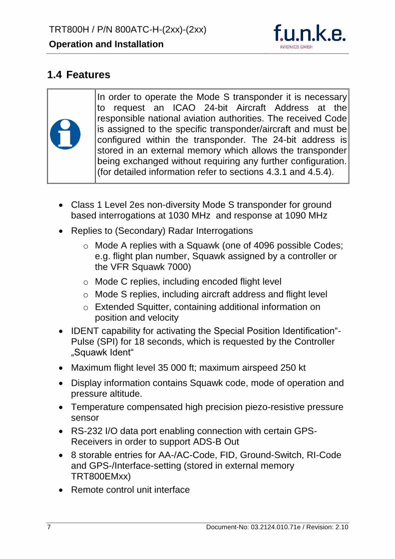
TRT800H PN 800ATC-H-(2xx)-(2xx)
Operation and Installation
8 Document-No 03212401071e Revision 210
15 Deviations and Important Notes
The following deviations have been granted by the FAA
The device is certified to FAA TSO-C112c in lieu of FAA TSO-C112d
Environmental Qualification Testing was performed according to RTCADO-160D in lieu of RTCADO-160F
The Software of this device was developed according to RTCA DO-178B Design Assurance Level D
The ADS-B function of this device has not been evaluated during the FAA TSO certification process other than to ensure non-interference Due to the SW assurance of DAL D the ADS-B function cannot be used in the US National Airspace
Connecting a GPS source will not comply to FAA certification requirements with regard to ADS-B
This device contains an altitude measuring device that has not been evaluated during the FAA TSO certification process other than to ensure non-interference
This feature must be evaluated for intended function during FAA installation approval
Compliance to RTCA DO-181D was verified by testing against EUROCAE ED-73C The two standards are technically identical with regard to the TRT800H
TRT800H PN 800ATC-H-(2xx)-(2xx)
Operation and Installation
9 Document-No 03212401071e Revision 210
2 OPERATION
21 Controls
ON OFF
bdquoSquawk Identldquo
Activate deactivate VFR
Change Active Standby
Squawk
Select Operation Mode
Cursor adjustment
Rotary Knob for adjusting values at the cursor position
active
Operation
Mode
standby Standby Squawk
Active Squawk
TRT800H PN 800ATC-H-(2xx)-(2xx)
Operation and Installation
10 Document-No 03212401071e Revision 210
IO ONOFF
Switch ON press button for approx 05 s
Switch OFFpress button for approx 3 s
VFR VFR
activatedeactivate VFR Squawk (press shortly)
store active Squawk as VFRVFRW-Squawk (press button 3 s rarr28)
CHANGE
change between active and standby-Squawk
works as cursor back button (opposite function of the cursor button) during entering values and also for navigating backwards through the configuration menu (rarr454)
ID IDENT
bdquoSquawk Identldquo sends Ident marking (SPI) for 18 s (rarr 29)
Enter Flight-ID (FID) setup (in standby mode press button for approx 5s)
MODE MODE Select transponder operational mode (rarr 26)
CURSOR Set position of Cursor
Rotary Knob
AdjustEnter values at current cursor position select options set standby Squawk (rarr 27)
TRT800H PN 800ATC-H-(2xx)-(2xx)
Operation and Installation
11 Document-No 03212401071e Revision 210
22 Switch ONOFF
Switch ON press IO for 05 s
Switch OFF press IO for 3 s
221 Display information after power up
After turning-on the display appears as follows (example)
If more than one configuration record is programmed the record selection menu appears (example)
Select the desired record (rotary switch) and confirm with MODE
If no external memory is connected or no 24bit address is defined the message ldquoCRADLE OFFrdquo appears In this case the device is working as ldquoMode AC onlyrdquo transponder
The transponder starts in STBY mode
2000 FL 030
STBY 7000
Cradle OFF
24D5F2 lt 000000 BE2343 000000 D4B3AA 000000 000000 000000
TRT800H V53
FPGA-Vers 102
Device Name
Software Version
Firmware Version
TRT800H PN 800ATC-H-(2xx)-(2xx)
Operation and Installation
12 Document-No 03212401071e Revision 210
23 Display - Indications
Value Meaning Remarks
7000 active Squawk
2000 Standby Squawk Could be changed with active Squawk by pressing
FL 030
FLerr
Flight Level
Invalid altitude measuring
Flight Level (in 100 ft steps)
Beyond -1000 35 000 ft C Mode gets inactive
ACS Operational Mode (STBY A-S ACS AC A)
Modes see section 26
IDT transmits Ident-Marking (SPI) ID (bdquoSquawk Identldquo) has been pressed ndash active for 18 s
Transponder replies
on Mode-S Mode-A or Mode-C interrogations
No indication on ADSB and squitter transmission
| Transponder is locked by a ground station and will be directly addressed
Lock Information (indicated below the diamond)
F
G
in-flight
on-ground
Ground-Switch-Info
(if installedavailable)
ACS
7000
TM
PLLTRX DC | BATDIM
IDT FL 030
STBY 2000 F
Passive Squawk
Active Squawk
Test mode indicatior
GND switch status
Operational Mode Standby
SPI indicator
Error indications
Reply indication
Lock out indication
Flight level
Backlight setup
Low battery ind
Operational Mode Active
TRT800H PN 800ATC-H-(2xx)-(2xx)
Operation and Installation
13 Document-No 03212401071e Revision 210
Value Meaning Remarks
Error indicators
PLL PLL Error Internal Error
TRX Transmit Failure Check antenna and wiring
DC Low internal voltage Internal error
FPG FPGA-Failure Internal error
BAT Battery Power too low maybe batterygenerator fault
24 Display-Brightness
In active mode (not standby) press for 2 s
Display indicates ldquoDIMrdquo Adjust brightness (DIM) with rotary knob
Return to normal operation press or wait 5 s
25 Flight-ID (FID)
The FID is an identifier required for Mode S Operation During future application of flight plans a FID could be assigned on a per flight basis If no FID is assigned (todayrsquos normal case) the registration marking of the aircraft should be used as FID The FID should not contain dashes or blanks The FID must not be confused with the 24-bit Aircraft Address
251 Display Flight-ID
Press MODE (repeatedly) until bdquoSTBYldquo appears
Press and hold ID while a counter is shown beside the active squawk During a few seconds Flight Identification is displayed
FID 02
A B C D E F G H
-
TRT800H PN 800ATC-H-(2xx)-(2xx)
Operation and Installation
14 Document-No 03212401071e Revision 210
252 Configure Flight-ID
Press MODE (repeatedly) until bdquoSTBYldquo appears
Press and hold ID while a counter is shown beside the active squawk Release ID when ldquoCHANGE FIDrdquo is displayed
Enter Flight-Id with cursor button and rotary knob
Press MODE to save and return to STBY
Please refer to section 454 for configuration of the 24-bit Address (AA) and Aircraft Category (AC)
26 Transponder Mode selection
Press MODE (repeatedly) to select from following Modes
STBY bdquoStandbyldquo Transponder does not respond to any interrogation Squitter and ADS-B output is not active
A C S bdquoMode A+C+Sldquo Standard condition transponder responds to mode A C and S interrogations
A ndash S bdquoMode A+S no Cldquo Altitude is not transmitted (neither on C nor on S requests) All other Mode-S data as well as Mode-A replies are transmitted
Enter FID left-aligned without any blanks or dashes () eg 12345621DEFAV for the marking D-EFAV The last remaining digits shall be filled with blanks
CHANGE FID
_ _ _ _ _ _ _ _ A B C D E F G H
- exit
TRT800H PN 800ATC-H-(2xx)-(2xx)
Operation and Installation
15 Document-No 03212401071e Revision 210
If no 24-bit address (AA) was defined or entered as ldquo000000ldquo the transponder operates as a Mode AC transponder in that case the following Modes are possible apart from Standby
A C ndash bdquoMode A+Cldquo Transponder replies only on Mode A and Mode-C interrogations
A ndash ndash bdquoMode Aldquo Transponder replies only on Mode A interrogations
In STBY (Standby) mode all transponder transmissions are disabled completely Therefore the transponder is not visible in this mode to air traffic control or the anti-collision systems onboard other aircrafts
Never use the STBY mode in flight unless you are requested to do so by air traffic control Always remember to put the transponder in active mode prior to take off
27 Squawk-Setting
The active Squawk is displayed in the upper line while the standby Squawk is presented at the lower line
Setting the Standby Squawk
Press to set the cursor (bdquo^ldquo) turn rotary knob to set numbers of the standby Squawk
Press to activate the Standby Squawk (this moves the current active Squawk into Standby)
28 VFR ndash Squawk
The transponder features a user-defined squawk code for VFR-flight (factory setting 7000)
Activate VFR-Squawk
Press VFR (bdquoVFRldquo is indicated) now the active Squawk is moved into Standby but not visible because the indication of the Standby Squawk is overlapped by bdquoVFRldquo
TRT800H PN 800ATC-H-(2xx)-(2xx)
Operation and Installation
16 Document-No 03212401071e Revision 210
Display Standby Squawk
Press VFR or or use the rotary knob (the VFR-Squawk remains active)
Example
VFR VFR
Now the Standby Squawk can be adjusted by using the rotary knob and activated with
In order to store the current active Squawk as new VFR-Squawk (replacing the factory setting 7000) Press and hold VFR until an bdquoSldquo is indicated (approx 3 s) after releasing the button bdquoVFRldquo is shown
29 ID ndash Special Position Identification (SPI) ldquoSquawk Identrdquo
Press ID to activate transmission of the special position identification pulse with every reply within 18 seconds ldquoIDTrdquo appears on the display
By pressing ID a special position identification pulse (SPI) is transmitted with every reply within 18 seconds which causes an accented marking on the Controllerrsquos screen The bdquoSpecial Position Identificationldquo has to be activated after the bdquoSquawk Identldquo request of the Controller
210 Error-Codes
Please refer to 23 Display - Indications for possible displayed errors
7000
FL 030
STBY 4700
7000
FL 030
STBY VFR
4700
FL 030
STBY 5600
TRT800H PN 800ATC-H-(2xx)-(2xx)
Operation and Installation
17 Document-No 03212401071e Revision 210
3 INSTALLATION
31 Notes
The following suggestions should be considered before installing
The assigned installation company will supply wiring For diagrams refer to 37 Wiring
Transponder External Memory all cables and antennas shall be installed according to bdquoFAA AC-14313-2A Acceptable Methods Techniques and Practices ndash Aircraft Alterationsldquo and the appropriate manufacturerrsquos instructions
32 Telecommunication data
Depending on your national telecommunications legislation the following data may be required when applying for the aircraft radio station license
Manufacturer funke AVIONICS GmbH
Type Designation TRT800H
EASA Number EASA21O269
Transmitter Power Output
126 W
Frequency 1090 MHz
Emission Designator 12M0M1D
33 Scope of Delivery
Item namenumber Description
TRT800H Transponder TRT800H
TRT800EMSS External Memory (Aircraft-Address-Adaptor with wiring)
M4X8ZSW (3 pieces) screw for panels up to 5 mm thickness
56S101A4 TNC antenna connector
03212401071e Manual bdquoOperation and Installationldquo
EASA Form 1
TRT800H PN 800ATC-H-(2xx)-(2xx)
Operation and Installation
18 Document-No 03212401071e Revision 210
34 Unpacking and Inspecting of the Equipment
Carefully unpack the equipment and inspect for transport damages If a damage claim has to be filed save the shipping container and all packing materials as evidence to your claim
35 Mounting
In cooperation with a maintenance shop location and kind of the installation are specified The maintenance shop can supply all cables Suitable sets of cables are available from funke AVIONICS GmbH
Select a position away from heat sources Provide space for adequate convection cooling
Leave sufficient space for the installation of cables and connectors
Avoid sharp bends and wiring close to control cables
Leave sufficient lead length for inspection or repair of the wiring of the connector (containing the memory) so that when the mounting hardware for the rear connectors is removed the assembly may be pulled forward several inches
Bend the harness at the rear connectors to inhibit water droplets (formed due to condensation) from collecting in the connector
For mounting detailsdrawing refer to chapter 3122 Mounting Advices
For storage or reshipment the original packaging should be used
TRT800H PN 800ATC-H-(2xx)-(2xx)
Operation and Installation
19 Document-No 03212401071e Revision 210
36 Equipment Connections
361 Electrical Connections
One 15 pin D-SUB miniature connector includes all electrical connections except for the antenna Use only an External Memory Adapter TRT800EMxx as this is part of the certification and includes a memory device in which the ICAO 24-bit Aircraft Address is stored
3611 Mutual Suppression
Other equipment on board (e g DME) may transmit in the same frequency band as the transponder
If such a device is installed a suppression wiring shall be installed in order to protect the receiving parts of the different devices from in-band transmissions
Mutual suppression is a synchronous pulse that is sent to the other equipment to suppress transmission of a competing transmitter for the duration of the pulse train transmission The transponder transmission may be suppressed by an external source and vice versa
To activate mutual suppression connect the SUPP_IO signal to the according signals of the other equipment
3612 Ground Switch
If an external Ground-Switch is connected to the transponder and activated in the setup the transponder can detect if the aircraft is airborne or on the ground This allows the transponder to automatically activate the Ground mode whenever the aircraft is on ground
In order to activate this feature the input bdquoFLY-GNDldquo must be connected to an external switch which connects the input pin with bdquoGNDldquo when the gear is weighted or remains open in the other case
This feature must additionally be activated in the Setup For details on configuration please refer to section 454
The (+UB)-wire has to protected by circuit breaker (2 Amp)
TRT800H PN 800ATC-H-(2xx)-(2xx)
Operation and Installation
20 Document-No 03212401071e Revision 210
3613 Auto-On
The Auto-On input allows to define how the transponder will behave when power is supplied to it
If the aircraft is equipped with a dedicated avionics master switch that switches the power supply to the transponder the pin Auto-On must be wired together with the UB+ pin to the avionic master switch The onoff button on the transponder is without function in that case The transponder will start automatically whenever power is supplied
On aircraft without such an avionics master switch the pin Auto-On must be left unconnected In this case the transponder must be switched on and off via the transponders onoff button on the front panel
362 Static Air Port
Install a silicon soft tube fitting the 5 mm static air hose at the backside of the transponder and secure plumbing with appropriate clamps
37 Wiring
371 Conductor Cross Section
Power Supply (Power GND) AWG20 (062 mmsup2)
Signals AWG22 (038 mmsup2)
The conductors must be approved for aircraft use
TRT800H PN 800ATC-H-(2xx)-(2xx)
Operation and Installation
21 Document-No 03212401071e Revision 210
372 Pin Assignment
The transponder may only be operated together with an external memory address adaptor TRT800EMxx
Pin Signal Remarks Adaptor
Typ(4)
TRT800
EM
Adaptor
Typ(4)
TRT800
EMSS
Adaptor Typ
TRT800
EMRS
1 GND -
2 Remote control(1) Input
3 EEPROM Signal TRT800EMxx internal
4 EEPROM Signal TRT800EMxx internal
5 TX RS-232 Serial Output
6 Switched +UB(1) Output
7 Remote control(1) Output
8 +UB power supply Input
9 GND -
10 EEPROM VCC TRT800EMxx internal
11 EEPROM GND TRT800EMxx internal
12 RX RS-232 Serial Input
13 Suppression Input Output
14 Auto-On(2) Input(2)
15 Fly-GND Switch(3) Input(3)
= in the plug and get out = in the plug and not get out ∕ = internal connection to the device
(1) SWITCHED +UB OUT Interface Remote control
May only be used for compatible funke AVIONICS devices Do not connect pins if interface is not used
(2) Auto-On Connect to +UB override front panel onoff button Leave unconnected to use front panel onoff button
(3) Ground Switch
FLY-GND
If an external Ground Switch is connected it must connect this pin to GND to indicate the on-ground condition Leave open otherwise
(4) Adaptors TRT800EM amp TRT800EMSS
Adaptor version does not provide full interface capability (see table for details)
TRT800H PN 800ATC-H-(2xx)-(2xx)
Operation and Installation
22 Document-No 03212401071e Revision 210
373 Cable plan External Memory EM800
3731 Cable plan TRT800EMRS (older version with interface remote)
to SN 90932013
DSUB 15pol
TRT800HTRT800A
lt PIN-5 gt
lt PIN-12gt
lt PIN-15gt
lt PIN-13gt
lt PIN-7 gt
lt PIN-2 gt
lt PIN-6 gt
lt PIN-1 gt
lt PIN-9 gt
lt PIN-8 gt
lt PIN-14gt
TXD
RXD
FLY_GND
SUPP_IO
GND
open
cable
ends
Remote Binder
Connector
female
white
black
yellow
red
shield
blue
red
brown
GND
+UB
AUTO-ON(2)(3)
black
white
red
yellow
shield
Binder Connector female
(solder side)
1 2 3 4 5 6 7 8
9 10 11 12 13 14 15
D-SUB Connector female
(solder side)
open
cable
ends
1 New interface available
-at TRT800H starting from SN 30430109 with SW V53
-at TRT800A starting with SW V53 2 New TRT800H interface starting from HW 60 3 port function not available at TRT800A
3
4 2
5 1
RMT-LIGHT
GND
RMT-TXD
RMT-SW+UB
RMT-RXD
RMT-TXD(1)
RMT-RXD(1)
RMT-SW+UB(2)(3)
RMT-LIGHT(2)
GND(1)
TRT800H PN 800ATC-H-(2xx)-(2xx)
Operation and Installation
23 Document-No 03212401071e Revision 210
3732 Cable plan TRT800EMRS (newer version with interface remote)
from SN 90932114
DSUB 15pol
TRT800HTRT800A
lt PIN-5 gt
lt PIN-12gt
lt PIN-15gt
lt PIN-13gt
lt PIN-7 gt
lt PIN-2 gt
lt PIN-6 gt
lt PIN-1 gt
lt PIN-9 gt
lt PIN-8 gt
lt PIN-14gt
TXD
RXD
FLY_GND
SUPP_IO
GND
open
cable
ends
Remote Binder
Connector
female
white
brown
yellow
green
shield
blue
red
brown
GND
+UB
AUTO-ON(2)(3)
brown
white
green
yellow
shield
Binder Connector female
(solder side)
1 2 3 4 5 6 7 8
9 10 11 12 13 14 15
D-SUB Connector female
(solder side)
open
cable
ends
1 New interface available
-at TRT800H starting from SN 30430109 with SW V53
-at TRT800A starting with SW V53 2 New TRT800H interface starting from HW 60 3 port function not available at TRT800A
3
4 2
5 1
RMT-LIGHT
GND
RMT-TXD
RMT-SW+UB
RMT-RXD
RMT-TXD(1)
RMT-RXD(1)
RMT-SW+UB(2)(3)
RMT-LIGHT(2)
GND(1)
TRT800H PN 800ATC-H-(2xx)-(2xx)
Operation and Installation
24 Document-No 03212401071e Revision 210
3733 Cable plan TRT800EMSS (newer version without interface remote)
from SN 91032115
The External ndash Memory ndash Address - Adapter TRT800EMxx contains electronic parts and must not be opened Opening or modifying the connector leads to the loss of airworthiness certification
DSUB 15pol
TRT800HTRT800A
lt PIN-5 gt
lt PIN-12gt
lt PIN-15gt
lt PIN-13gt
lt PIN-1 gt
lt PIN-9 gt
lt PIN-8 gt
lt PIN-14gt
TXD
RXD
FLY_GND
SUPP_IO
GND
open
cable
ends
white
brown
yellow
green
shield
blue
red
brown
GND
+UB
AUTO-ON(2)(3)
open
cable
ends
2 New TRT800H interface starting from HW 60 3 port function not available at TRT800A
1 2 3 4 5 6 7 8
9 10 11 12 13 14 15
D-SUB Connector female
(solder side)
TRT800H PN 800ATC-H-(2xx)-(2xx)
Operation and Installation
25 Document-No 03212401071e Revision 210
38 Antenna
381 Antenna Selection
Recommended antennas see section 311 Accessories
Choose an antenna type compatible with the vehicle and the mounting location
Specified features depend on proper installation of the antenna
The radiation pattern needs to be verified considering aircraft type and mounting location
The electrical interference between the antenna and any other equipment must be taken into account in such a way that no reduction of the performance of any other system will occur
Install only certified antennas
382 Installation Recommendation
Take note of the antenna manufacturerrsquos instructions
The usually deployed Dipole- or Blade antennas necessarily require a high frequency capable solid metal ground plane at the antenna base
For installation in composite aircrafts ground planes are to be added The ground plane should be as large as possible but in any case not smaller than 10 cm x 10 cm If in doubt please contact the aircraft manufacturer
Keep away three feet from any other antenna
Pursue mounting in vertical position under the belly in flight direction
383 Antenna Wiring
Suitable antenna cables see section 311 Accessories
Keep wiring as short as possible
The smallest cable bend radius is 10cm Avoid sharp bends
Keep away from an ADF antenna cable at least 12 inches
Electrical connections to the antenna shall be protected against moisture to avoid loss of efficiency
TRT800H PN 800ATC-H-(2xx)-(2xx)
Operation and Installation
26 Document-No 03212401071e Revision 210
39 Post-Installation Check
All steering and control functions of the aircraft are to be examined in order to exclude disturbances by the wiring
The most important factor in the transponder configuration is the setting of the ICAO address (see section 454)
Attenuation from antenna to transponder at 1090 MHz must not exceed 15 dB
A certified maintenance shop must verify proper operation of the transponder by testing in accordance with Appendix F of ldquo14 CFR Part 43 ndash ATC Transponder Tests and Inspectionsrdquo
TRT800H PN 800ATC-H-(2xx)-(2xx)
Operation and Installation
27 Document-No 03212401071e Revision 210
310 Starting Up
Turn the transponder on with IO After start-up the following screens appear
311 Accessories
Part Number Description
TRKABEL1 Antenna cable 10 m (32 ft) TNC BNC
TRKABEL2 Antenna cable 25 m (82 ft) TNC BNC
TRKABEL3 Antenna cable 40 m (132 ft) TNC BNC
TRKABEL4 Antenna cable 65 m (213 ft) TNC BNC
TRT800EMRS External-Memory (Aircraft-Address-Adaptor) Connection cable with interface TRT-Remote control
CI-105 TransponderDME Antenna TSO C66b C74c
CI105 Comant Industries Inc
Height 325rdquo Weight 90 g (02 lbs)
AV22 Transponder Rod antenna TSO C74c
AV-22 R A Miller Industries
The TRT800H starts in standby mode (indicated with STBY) In order to change into operational mode (indicated with ACS) press MODE If ground switch is connected and status ldquoin flightrdquo is selected TRT800H starts in active mode
Very important is the correct configuration of the 24bit Aircraft-Address (see 454 General Setup)
TRT800H V53
FPGA-Vers 102
2000 FL 030
STBY 7000
TRT800H PN 800ATC-H-(2xx)-(2xx)
Operation and Installation
28 Document-No 03212401071e Revision 210
312 Drawings
3121 Dimensions
20mm15 mm
170 mm
TRT800TRT800H
65 mm
65
mm
Oslash 57 mm
Static Air
Antenna
PowerRS232
3122 Mounting Advices
Connections Area
8
0 m
m
Panel Cut-out
470 mm
470
mm
575 mm
4 x Oslash 4 mm
Oslash
Connector (plug) has to be clamped with both spring locks
No screws may be turned in more than max 15mm into the device ndash even if no hard limit is noticeable
Fixing clips (spring) left right
TRT800H PN 800ATC-H-(2xx)-(2xx)
Operation and Installation
29 Document-No 03212401071e Revision 210
4 TRANSPONDER SETTINGS
41 Overview
The TRT800H is capable of storing the following information
ICAO 24-Bit Aircraft-Address (AA)
Aircraft Category (AC)
Flight Identification (FID)
Ground-Switch (YesNo)
Speed Category (RI)
RS232 Interface Configuration
All of these data are configurable in the Setup and are stored in the external memory module integrated within the housing of the D-Sub connector (included in the delivery)
The cable with this connector shall remain in the aircraft even if the unit is removed to ensure that the ICAO 24bit aircraft address is fixed to the aircraft
Additionally the following usertransponder related settings are stored transponder internally
Active Squawk
Passive Squawk
VFR Squawk
Altitude offset
Display brightness
42 Display Configuration Summary
Transponder provides the opportunity to show summary of complete current settings To access configuration summary pages push and hold
ID in Standby mode Release ID if ldquoSHOW SETUPrdquo is displayed The summary is subdivided into the following pages
TRT800H PN 800ATC-H-(2xx)-(2xx)
Operation and Installation
30 Document-No 03212401071e Revision 210
Page 1
Aircraft Address
Aircraft Category
Flight Identification
MODE
Page 2 Speed Category
Ground Switch option
Remote Header option
MODE
Page 3 RS-232 Settings
Protocol baud rate position (if available)1
MODE
Page 4 Altitude correction settings
(part 1)
MODE
Page 5 Altitude correction settings
(part 2)
Note 1 Position data will only be displayed if
a GPS protocol is set as interface protocol (NMEA FREEFLIGHT AR-NAV)
18000 ft 0ft 25000 ft + 100ft 35000 ft - 50ft
exit
ALTITUDE CORRECTION 2000 ft 0ft 10000 ft + 100ft next
RS-232 NMEA Baud 4800 Pos 481 99 next
Speed Cat 8 Ground Sw YES Remote Hd NO next
AA F E 1 2 3 4 AC 1 9 FID 4 4 E 1 2 3 next
TRT800H PN 800ATC-H-(2xx)-(2xx)
Operation and Installation
31 Document-No 03212401071e Revision 210
GPS receiver is connected and transmits data (if not ldquoPos no datardquo is displayed)
a valid position is transmitted (if not ldquoPos wrong datardquo is displayed)
While configuration summary page is displayed no new position data will be processed
43 General settings
431 ICAO 24-Bit Aircraft Address (AA)
Ask your national aviation authority (e g in Germany LBA Referat B5 Department ldquoVerkehrszulassungrdquo) how to obtain the AA In the case of aerial sports equipment the contact point would be the respective associations Only the assigned AA has to be used and must not be modified at any time because a duplicate address would jeopardize the data surveillance and integrity figures of Mode S
If no AA is stored after power on the display shows ldquoCRADLE OFFrdquo and the transponder operates in Mode AC
(Configuration of the AA see section 454)
432 Aircraft Category (AC)
Code Description Code Description
11 Emergency Vehicle 1C Ultra-Light Paraglider
12 Service Vehicle 1E Drone
19 Glider 21 Aircraft (D-Exxx) lt 15500 lbs Motor Glider (D-Kxxx)
1A Balloon amp Airship 22 Aircraft ge 15500 lbslt 75000 lbs
1B Paratrooper 27 Rotorcraft
Only one of the Codes mentioned in the table above must be used
Setuprarr454
Setuprarr454
TRT800H PN 800ATC-H-(2xx)-(2xx)
Operation and Installation
32 Document-No 03212401071e Revision 210
433 Flight-ID (FID)
Per ICAO regulation Mode-S data must contain a valid flight identification (FID) to ensure that the correlation between flight plan and radar data will work automatically
FID setting is required to correspond to the aircraft identification that has been specified at item 7 of the ICAO flight plan It contains seven characters at a maximum (left-aligned no additional zeros dashes or spacesblanks)
For an aircraft using a company call sign the Flight-ID mostly consists of the ICAO three-letter designator for the aircraft operator followed by an identification code eg KLM511 BAW213 JTR25
If no company call sign is used or no flight plan is filed the default FID to be set consists of the registration marking of the aircraft (eg DEABC) with no dashes spacesblanks or additional zeros even if they are included in the registration marking on the aircraft (tail number) While entering the FID into the transponder the last remaining digits must be filled with blanks
The ICAO Flight Plan only specifies 7 characters for FID funke AVIONICS reserves 8 characters as stated in ED-73B for further expansion of the flight plan
The user shall only program 7 characters for FID
Setuprarr454
TRT800H PN 800ATC-H-(2xx)-(2xx)
Operation and Installation
33 Document-No 03212401071e Revision 210
434 Reply Information - Speed Category (RI)
Besides AA AC and FID another important part of the Mode-S data is the Speed Category of the respective aircraft This speed category shall be configured in the setup and must contain one of the following codes
Code Description
08 No maximum airspeed data available
09 Maximum airspeed le 75 kt
10 75 kt gt maximum airspeed le 150 kt
11 150 kt gt maximum airspeed le 300 kt
12 300 kt gt maximum airspeed le 600 kt
13 600 kt gt maximum airspeed le 1200 kt
14 Maximum airspeed gt 1200 kt
15 Not assigned
44 Optional settings
441 Option Ground-Switch
If a ground switch is connected (and enabled in setup) the transponder is able to determine on-ground and in-flight state On-ground state is activated automatically once the gear touches the ground On-ground state is indicated on display by symbol G (apart from lsquoFrsquo for In-flight-state)
In On-ground-state the transponder will reply differently to certain addressed interrogations Also the transmission rate of some periodically sent data (squitters ADS-B) is reduced This allows ATC to distinguish between airborne aircraft and those on the ground and it reduces the Mode S channel load
For small aircraft authorities normally do not require such a ground switch In this case the transponder will use the same data formats on the ground as in the airborne state
Setuprarr454 Wiringrarr373
Setuprarr454
TRT800H PN 800ATC-H-(2xx)-(2xx)
Operation and Installation
34 Document-No 03212401071e Revision 210
442 Option Remote Header
The transponder provides a TRT800RT remote control interface If a remote header TRT800RT is connected transponder can be remote controlled via this interface Remote interface provides control of all standard user inputs available during standard operational mode For more information see TRT800RT manual Remote control interface de-activation is setup configurable Remote control interface must only be connected to TRT800RT
443 Serial Interface (RS232)
Using serial interface a GPS receiver can be connected to broadcast own position via ADS-B Out position message Position could be received by other appropriately equipped aircrafts and processed for collision avoidance ADS-B Out functionality
The ADS-B function of this device has not been evaluated during the FAA TSO certification process other than to ensure non-interference Due to the SW assurance of DAL D the ADS-B function cannot be used in the US National Airspace Connecting a GPS source will not comply to FAA certification requirements with regard to ADS-B
Supported formatsprotocols are
Option Description Baud rate
FREEFLIGHT GPSWAAS Sensor 1201
NexNav NNL 3101
19200
AR-NAV Bendix King
KLN 89B KLN 94 ldquoStandard RS232 Sentencerdquo
KMD 150 ldquoSentence Type 1rdquo
Garmin 400 Series ldquoSentence Type 1rdquo (with and without altitude data)
9600
NMEA NMEA-Format data format RMC is expected
4800
Setuprarr454 Wiringrarr373
Setuprarr454 Wiringrarr373
TRT800H PN 800ATC-H-(2xx)-(2xx)
Operation and Installation
35 Document-No 03212401071e Revision 210
Option Description Baud rate
FAVISIA Glass Cockpit support
FAVISIA Data format to be processed in FAVISIA avionics suite
-
FAVISIA+GPS Data format to be processed in FAVISIA avionics suite (output) and additional processing of incoming NMEA GPS-Receiver position data to support the ADS-B Out functionality
4800
Other
Comm-AB-support
Data format for special purpose An additional data link processor allows COMM-AB operation and processing of the position information of a flight management system simultaneously
38400
Disabled No communication via RS232 interface -
444 Altitude CorrectionOffset
The TRT800H has an integrated temperature compensated high-precision pressure sensor This sensor is factory-calibrated so that it will yield accurate flight level (uncorrected pressure altitude) within the entire altitude range
However due to differences in calibration of the TRT800H pressure sensor and the altimeter in the cockpit it may become necessary to adjust the TRT800H pressure readings so that the value indicated and transmitted by the TRT800H corresponds to the indication of the primary altimeter seen by the pilot within 125 feet (as specified in ETSO C88aSAE AS 8003)
Setting for all described GPS-systems
1 2 position messages per 2 sec
Setuprarr455
TRT800H PN 800ATC-H-(2xx)-(2xx)
Operation and Installation
36 Document-No 03212401071e Revision 210
The check for correspondence between the primary altimeter and the TRT800H is usually performed every 24 months as part of the aircrafts altimeter checks
Altitude correction is based on setup configurable offset values at five interpolation points ( 2000 8000 18000 25000 and 35000 ft)The offset value itself is limited to a range from -100 to + 100ft at each point (10ft steps)
45 Setup Procedure
Programming of the ICAOA 24-bit Aircraft Address and of the Aircraft Category shall be executed by qualified personnel only
A wrong Aircraft Address or Flight ID may cause serious problems ATC or with ACASTCAS systems
Pilot and owner are responsible for correctly set transponder data
451 Setup Menu Control
In order to access the functions described in the following paragraphs push and hold ID in Standby mode Release ID if desired counter value menu name is displayed to enter the menu The following menu entries are selectable
Count Displayed Name Function
03 FID FID is displayed
48 CHANGE FID Enter FID setup page
913 SHOW SETUP Enter setup summary listed on different pages (no changes possible)
2528 ENTER SETUP Enter transponder general configuration pages
3134 ALTITUDE CORRECTION
Enter altitude correction menu
TRT800H PN 800ATC-H-(2xx)-(2xx)
Operation and Installation
37 Document-No 03212401071e Revision 210
452 Transponder configurationrecord structure
Aircraft related parts of transponder configuration are stored in one out of eight possible records (record=presetting) Each record contains the following information
Aircraft Address (AA 24bit)
Aircraft category (AC)
Flight identification (FID 6-8 numbersletters)
RS-232 Interface setting (eg GPS protocol)
Ground-Switch setting (Installed YesNo)
Speed category (RI) of the respective aircraft
Remote Header setting (Installed YesNo)
User related settings (eg squawk codes display brightness) are stored once in one global record (transponder internally)
453 Transponder configurationrecord handling
At least one record is stored in external memory Up to 8 records can be additional be applied during setup process
If more than one record is applied the active record must be selected out of a list (determined by FID) during start-up of the transponder
Previously applied records can be deleted again by filling FID with zerorsquos only
454 General Setup
Any menu item can be passed by MODE If no changes are made the original settings will remain stored Modification of one menu item does not impact the others No entries will be deleted
TRT800H PN 800ATC-H-(2xx)-(2xx)
Operation and Installation
38 Document-No 03212401071e Revision 210
Step Display (Example)
1 Start-up Transponder
2 Ensure the transponder-mode is bdquoSTBYldquo If necessary change the mode by pressing MODE
3 Press ID A counter is shown at the upper-right corner Hold ID till ldquoENTER SETUPrdquo is displayed
4 After release of ID the first setup menu is displayed
5 helliphellipselect position (^)
rotary knobchange value
MODE
6 With the rotary knob you can select bdquoyesldquo if a Ground Switch is installed if not select ldquonordquo and proceed with step 7
MODE
Record 1
GND Switch YesNo
next
AA EF123456
AC 18
FID ^BCDEFG
next
AA EF123456
AC 18
FID ABCDEFG
next
ENTER SETUP 26
2000 FL 030
STBY 7000
TRT800H PN 800ATC-H-(2xx)-(2xx)
Operation and Installation
39 Document-No 03212401071e Revision 210
Step Display (Example)
7 At this stage the respective speed category shall be selected by using the rotary knob
MODE
8 At this stage a GPS receiver for ADS-B Out can be selected (Selectable by rotary knob)
MODE
9 At this stage remote interface for communication between TRT800H and remote header can be activated (Selectable by rotary knob)
Remote interface must only be activated if a remote header is connected
MODE
10 With ID further Records can now be created and configured as described in the aforementioned steps At start-up of the transponder one of the defined records with all associated configurations need to be selected
MODE
Records ID=Edit Records
EXIT
Record 1
REMOTE Header YesNo
next
Record 1
GPSINTEXT NMEA
next
Record 1
Speed Cat 08-15
next
TRT800H PN 800ATC-H-(2xx)-(2xx)
Operation and Installation
40 Document-No 03212401071e Revision 210
Step Display (Example)
11 You have now left the configuration mode and are back in normal operation
12 Switch off the transponder
13 Switch on the transponder Your ICAO 24-Bit Aircraft Address is now stored
TRT800H V53
FPGA-Vers 102
2000 FL 030
STBY 7000
TRT800H PN 800ATC-H-(2xx)-(2xx)
Operation and Installation
41 Document-No 03212401071e Revision 210
455 Altitude Correction Setup
Altitude correction setup shall be executed by qualified personnel only
Pilot and owner are responsible for correctly set altitude offset values
The usesetting of altitude correction values is only necessary in exceptional cases (see 444 for details)
Altitude correction is based on five interpolation points ( 2000 10000 18000 25000 and 35000 ft)The offset value at each interpolation point can be adjusted in a range from -100 to + 100ft at each point (10ft steps) Offset values set to zero at each interpolation point deactivates altitude correction (defaultfactory setting)
Step Display (Example)
1 Start-up Transponder
2 Ensure the transponder-mode is bdquoSTBYldquo If necessary change the mode by pressing MODE
3 Press ID A counter is shown at the upper-right corner Hold ID till ldquoALTITUDE OFFSETrdquo is displayed
ALTITUDE OFFSET 33
2000 FL 030
STBY 7000
Descriptionrarr444
TRT800H PN 800ATC-H-(2xx)-(2xx)
Operation and Installation
42 Document-No 03212401071e Revision 210
Step Display (Example)
4 After release of ID the first altitude level + corresponding offset value is displayed
5 Change offset value with rotary knob
MODE
6 (9) Repeat last step for another 4 altitude levels 10000ft 18000ft 25000ft 35000ft
MODE
10 You have now left the configuration mode and are back in normal operation
Switch off the transponder
11 Switch on the transponder New altitude offset values will now be used for altitude calculation
Altitude 10000 ft
Offset 0 ft
nextexit
Altitude 2000 ft
Offset 0 ft
next
TRT800H V53
FPGA-Vers 102
2000 FL 030
STBY 7000
Altitude 2000 ft
Offset 0 ft
next
TRT800H PN 800ATC-H-(2xx)-(2xx)
Operation and Installation
43 Document-No 03212401071e Revision 210
5 APPENDIX
51 Technical Data
Compliance CS-ETSO-2C112a
EASA21O269
FAA TSO-C112c
Applicable Documents CS-ETSO-2C112a
FAA TSO-C112c
EUROCAE ED-73C Class 1 Level 2es
RTCA DO-181D Class 1 Level 2es
EUROCAE ED-26
RTCA DO-160D
RTCA DO-178B Software-Level D
Temperature Ranges
Operation -20 degC to +55 degC for 30 min +70degC
Storage -55 degC to +85 degC
Altitude Range le 35 000 ft
Speed Range le 250 kt (TAS)
Shock 6 G Operation
20 G crash safety
Environmental Categories RTCA DO-160D EnvCat [C1Z]CAA[SM]XXXXXXZBAAA[TT]M[B3F3]XXA
Power Supply 138 VDC (10 VDC 16 VDC)
040 A 138 VDC (typ)
070 A 138 VDC (max)
10 W (max)
TRT800H PN 800ATC-H-(2xx)-(2xx)
Operation and Installation
44 Document-No 03212401071e Revision 210
Fuse External 2A-slow-blow fuse
Mounting Panel cut-out d=575 mm
Weight 06 kg (132 lbs)
Receiver Characteristics
Sensitivity
RF input power level resulting in a 90 reply rate
A MTL for ATCRBS and ATCRBSMode S All-Call interrogations -74 dBm plusmn3 dB
B MTL for Mode S interrogations -74 dBm plusmn 3 dB
Reply transmission frequency
1090 plusmn 1 MHz
RF Peak Power Output 21 dBW (126 W) at antenna base (with maximum cable attenuation of 15 dB)
Squitter (ADS-B) transmitted at random intervals uniformly distributed over the range from 08 to 12 seconds full self-verification of data and occurrence
Mode S Elementary Surveillance
ICAO 24-bit Aircraft Address (Hex-Code)
aircraft address as assigned by national aviation authority
FID Flight ID Flight Plan call sign or aircraft registration marking
Capability Report Reports the available data and means by which the transponder can report
Pressure Altitude Up to 35 000 ft in 25 ft increments
Flight Status in-flight on-ground
Mode S Enhanced Surveillance
Level 2es Comm-A Comm-B 56112-Bit-Messages
SI-capability
TRT800H PN 800ATC-H-(2xx)-(2xx)
Operation and Installation
45 Document-No 03212401071e Revision 210
52 Environmental Conditions
Characteristic DOndash160D Section Cat Condition
Temperature Altitude 40
C1
Low ground survival temperature
451 ndash 55degC
Low operating temperature 451 ndash 20degC
High ground survival Temperature
452 + 85degC
High Short-time Operating Temperature
452 + 70degC
High Operating Temperature 453 + 55degC
In-Flight Loss of Cooling 454 Z No auxiliary cooling required
Altitude 461 C1 35 000 ft
Temperature Variation 50 C 2degC change rate minimum per minute
Humidity 60 A
Shock 70 A
6 G operational shocks
20 G Crash Safety
Test Type R in all 6 directions
Vibration 80 S Vibration Curve M
Explosion Proofness 90 X No test required
Water Proofness 100 X No test required
Fluids Susceptibilities 110 X No test required
Sand and Dust 120 X No test required
Fungus Resistance 130 X No test required
Salt Spray 140 X No test required
Magnetic Effect 150 Z Less than 03 m
Power Input (DC) 160 B
Voltage Spike Conducted 170 A
Audio Frequency Conducted Susceptibility
180 A
TRT800H PN 800ATC-H-(2xx)-(2xx)
Operation and Installation
46 Document-No 03212401071e Revision 210
Characteristic DOndash160D Section Cat Condition
Induced Signal Susceptibility 190 A
Radio Frequency Susceptibility
200 TT
Emission of RF Energy 210 M
Lightning Induced Transient Susceptibility
220 B3F3
Lightning Direct Effects 230 X No test required
Icing 240 X No test required
Electrostatic Discharge (ESD) 250 A
53 DO-178B Open Problem Reports
There are no open problem reports for the software of this device
TRT800H PN 800ATC-H-(2xx)-(2xx)
Operation and Installation
47 Document-No 03212401071e Revision 210
Notes
f funke funke means ndash fabrication utilities network know-how engineering
funke AVIONICS GmbH Heinz-Strachowitz-Str 4
DE-86807 Buchloe Germany
phone +49-8241 80066 0
fax +49-8241 80066 99 E-mail
servicefunkeavionicsde wwwfunkeavionicsde
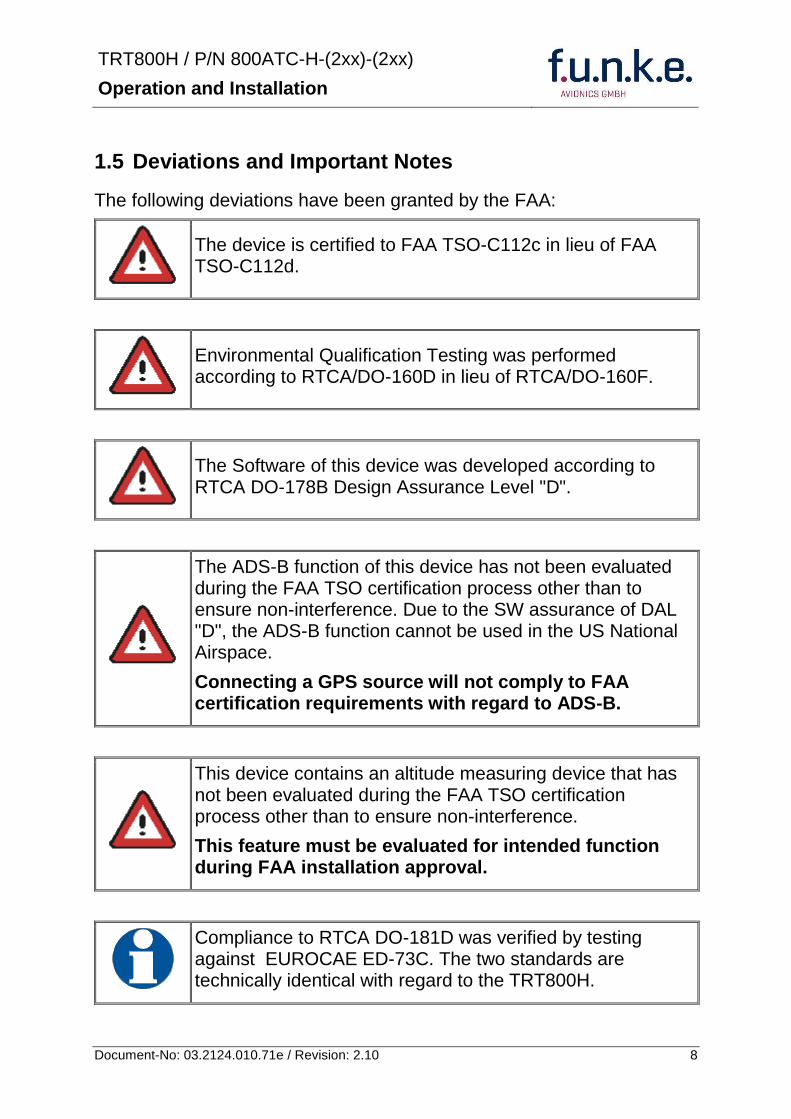
TRT800H PN 800ATC-H-(2xx)-(2xx)
Operation and Installation
9 Document-No 03212401071e Revision 210
2 OPERATION
21 Controls
ON OFF
bdquoSquawk Identldquo
Activate deactivate VFR
Change Active Standby
Squawk
Select Operation Mode
Cursor adjustment
Rotary Knob for adjusting values at the cursor position
active
Operation
Mode
standby Standby Squawk
Active Squawk
TRT800H PN 800ATC-H-(2xx)-(2xx)
Operation and Installation
10 Document-No 03212401071e Revision 210
IO ONOFF
Switch ON press button for approx 05 s
Switch OFFpress button for approx 3 s
VFR VFR
activatedeactivate VFR Squawk (press shortly)
store active Squawk as VFRVFRW-Squawk (press button 3 s rarr28)
CHANGE
change between active and standby-Squawk
works as cursor back button (opposite function of the cursor button) during entering values and also for navigating backwards through the configuration menu (rarr454)
ID IDENT
bdquoSquawk Identldquo sends Ident marking (SPI) for 18 s (rarr 29)
Enter Flight-ID (FID) setup (in standby mode press button for approx 5s)
MODE MODE Select transponder operational mode (rarr 26)
CURSOR Set position of Cursor
Rotary Knob
AdjustEnter values at current cursor position select options set standby Squawk (rarr 27)
TRT800H PN 800ATC-H-(2xx)-(2xx)
Operation and Installation
11 Document-No 03212401071e Revision 210
22 Switch ONOFF
Switch ON press IO for 05 s
Switch OFF press IO for 3 s
221 Display information after power up
After turning-on the display appears as follows (example)
If more than one configuration record is programmed the record selection menu appears (example)
Select the desired record (rotary switch) and confirm with MODE
If no external memory is connected or no 24bit address is defined the message ldquoCRADLE OFFrdquo appears In this case the device is working as ldquoMode AC onlyrdquo transponder
The transponder starts in STBY mode
2000 FL 030
STBY 7000
Cradle OFF
24D5F2 lt 000000 BE2343 000000 D4B3AA 000000 000000 000000
TRT800H V53
FPGA-Vers 102
Device Name
Software Version
Firmware Version
TRT800H PN 800ATC-H-(2xx)-(2xx)
Operation and Installation
12 Document-No 03212401071e Revision 210
23 Display - Indications
Value Meaning Remarks
7000 active Squawk
2000 Standby Squawk Could be changed with active Squawk by pressing
FL 030
FLerr
Flight Level
Invalid altitude measuring
Flight Level (in 100 ft steps)
Beyond -1000 35 000 ft C Mode gets inactive
ACS Operational Mode (STBY A-S ACS AC A)
Modes see section 26
IDT transmits Ident-Marking (SPI) ID (bdquoSquawk Identldquo) has been pressed ndash active for 18 s
Transponder replies
on Mode-S Mode-A or Mode-C interrogations
No indication on ADSB and squitter transmission
| Transponder is locked by a ground station and will be directly addressed
Lock Information (indicated below the diamond)
F
G
in-flight
on-ground
Ground-Switch-Info
(if installedavailable)
ACS
7000
TM
PLLTRX DC | BATDIM
IDT FL 030
STBY 2000 F
Passive Squawk
Active Squawk
Test mode indicatior
GND switch status
Operational Mode Standby
SPI indicator
Error indications
Reply indication
Lock out indication
Flight level
Backlight setup
Low battery ind
Operational Mode Active
TRT800H PN 800ATC-H-(2xx)-(2xx)
Operation and Installation
13 Document-No 03212401071e Revision 210
Value Meaning Remarks
Error indicators
PLL PLL Error Internal Error
TRX Transmit Failure Check antenna and wiring
DC Low internal voltage Internal error
FPG FPGA-Failure Internal error
BAT Battery Power too low maybe batterygenerator fault
24 Display-Brightness
In active mode (not standby) press for 2 s
Display indicates ldquoDIMrdquo Adjust brightness (DIM) with rotary knob
Return to normal operation press or wait 5 s
25 Flight-ID (FID)
The FID is an identifier required for Mode S Operation During future application of flight plans a FID could be assigned on a per flight basis If no FID is assigned (todayrsquos normal case) the registration marking of the aircraft should be used as FID The FID should not contain dashes or blanks The FID must not be confused with the 24-bit Aircraft Address
251 Display Flight-ID
Press MODE (repeatedly) until bdquoSTBYldquo appears
Press and hold ID while a counter is shown beside the active squawk During a few seconds Flight Identification is displayed
FID 02
A B C D E F G H
-
TRT800H PN 800ATC-H-(2xx)-(2xx)
Operation and Installation
14 Document-No 03212401071e Revision 210
252 Configure Flight-ID
Press MODE (repeatedly) until bdquoSTBYldquo appears
Press and hold ID while a counter is shown beside the active squawk Release ID when ldquoCHANGE FIDrdquo is displayed
Enter Flight-Id with cursor button and rotary knob
Press MODE to save and return to STBY
Please refer to section 454 for configuration of the 24-bit Address (AA) and Aircraft Category (AC)
26 Transponder Mode selection
Press MODE (repeatedly) to select from following Modes
STBY bdquoStandbyldquo Transponder does not respond to any interrogation Squitter and ADS-B output is not active
A C S bdquoMode A+C+Sldquo Standard condition transponder responds to mode A C and S interrogations
A ndash S bdquoMode A+S no Cldquo Altitude is not transmitted (neither on C nor on S requests) All other Mode-S data as well as Mode-A replies are transmitted
Enter FID left-aligned without any blanks or dashes () eg 12345621DEFAV for the marking D-EFAV The last remaining digits shall be filled with blanks
CHANGE FID
_ _ _ _ _ _ _ _ A B C D E F G H
- exit
TRT800H PN 800ATC-H-(2xx)-(2xx)
Operation and Installation
15 Document-No 03212401071e Revision 210
If no 24-bit address (AA) was defined or entered as ldquo000000ldquo the transponder operates as a Mode AC transponder in that case the following Modes are possible apart from Standby
A C ndash bdquoMode A+Cldquo Transponder replies only on Mode A and Mode-C interrogations
A ndash ndash bdquoMode Aldquo Transponder replies only on Mode A interrogations
In STBY (Standby) mode all transponder transmissions are disabled completely Therefore the transponder is not visible in this mode to air traffic control or the anti-collision systems onboard other aircrafts
Never use the STBY mode in flight unless you are requested to do so by air traffic control Always remember to put the transponder in active mode prior to take off
27 Squawk-Setting
The active Squawk is displayed in the upper line while the standby Squawk is presented at the lower line
Setting the Standby Squawk
Press to set the cursor (bdquo^ldquo) turn rotary knob to set numbers of the standby Squawk
Press to activate the Standby Squawk (this moves the current active Squawk into Standby)
28 VFR ndash Squawk
The transponder features a user-defined squawk code for VFR-flight (factory setting 7000)
Activate VFR-Squawk
Press VFR (bdquoVFRldquo is indicated) now the active Squawk is moved into Standby but not visible because the indication of the Standby Squawk is overlapped by bdquoVFRldquo
TRT800H PN 800ATC-H-(2xx)-(2xx)
Operation and Installation
16 Document-No 03212401071e Revision 210
Display Standby Squawk
Press VFR or or use the rotary knob (the VFR-Squawk remains active)
Example
VFR VFR
Now the Standby Squawk can be adjusted by using the rotary knob and activated with
In order to store the current active Squawk as new VFR-Squawk (replacing the factory setting 7000) Press and hold VFR until an bdquoSldquo is indicated (approx 3 s) after releasing the button bdquoVFRldquo is shown
29 ID ndash Special Position Identification (SPI) ldquoSquawk Identrdquo
Press ID to activate transmission of the special position identification pulse with every reply within 18 seconds ldquoIDTrdquo appears on the display
By pressing ID a special position identification pulse (SPI) is transmitted with every reply within 18 seconds which causes an accented marking on the Controllerrsquos screen The bdquoSpecial Position Identificationldquo has to be activated after the bdquoSquawk Identldquo request of the Controller
210 Error-Codes
Please refer to 23 Display - Indications for possible displayed errors
7000
FL 030
STBY 4700
7000
FL 030
STBY VFR
4700
FL 030
STBY 5600
TRT800H PN 800ATC-H-(2xx)-(2xx)
Operation and Installation
17 Document-No 03212401071e Revision 210
3 INSTALLATION
31 Notes
The following suggestions should be considered before installing
The assigned installation company will supply wiring For diagrams refer to 37 Wiring
Transponder External Memory all cables and antennas shall be installed according to bdquoFAA AC-14313-2A Acceptable Methods Techniques and Practices ndash Aircraft Alterationsldquo and the appropriate manufacturerrsquos instructions
32 Telecommunication data
Depending on your national telecommunications legislation the following data may be required when applying for the aircraft radio station license
Manufacturer funke AVIONICS GmbH
Type Designation TRT800H
EASA Number EASA21O269
Transmitter Power Output
126 W
Frequency 1090 MHz
Emission Designator 12M0M1D
33 Scope of Delivery
Item namenumber Description
TRT800H Transponder TRT800H
TRT800EMSS External Memory (Aircraft-Address-Adaptor with wiring)
M4X8ZSW (3 pieces) screw for panels up to 5 mm thickness
56S101A4 TNC antenna connector
03212401071e Manual bdquoOperation and Installationldquo
EASA Form 1
TRT800H PN 800ATC-H-(2xx)-(2xx)
Operation and Installation
18 Document-No 03212401071e Revision 210
34 Unpacking and Inspecting of the Equipment
Carefully unpack the equipment and inspect for transport damages If a damage claim has to be filed save the shipping container and all packing materials as evidence to your claim
35 Mounting
In cooperation with a maintenance shop location and kind of the installation are specified The maintenance shop can supply all cables Suitable sets of cables are available from funke AVIONICS GmbH
Select a position away from heat sources Provide space for adequate convection cooling
Leave sufficient space for the installation of cables and connectors
Avoid sharp bends and wiring close to control cables
Leave sufficient lead length for inspection or repair of the wiring of the connector (containing the memory) so that when the mounting hardware for the rear connectors is removed the assembly may be pulled forward several inches
Bend the harness at the rear connectors to inhibit water droplets (formed due to condensation) from collecting in the connector
For mounting detailsdrawing refer to chapter 3122 Mounting Advices
For storage or reshipment the original packaging should be used
TRT800H PN 800ATC-H-(2xx)-(2xx)
Operation and Installation
19 Document-No 03212401071e Revision 210
36 Equipment Connections
361 Electrical Connections
One 15 pin D-SUB miniature connector includes all electrical connections except for the antenna Use only an External Memory Adapter TRT800EMxx as this is part of the certification and includes a memory device in which the ICAO 24-bit Aircraft Address is stored
3611 Mutual Suppression
Other equipment on board (e g DME) may transmit in the same frequency band as the transponder
If such a device is installed a suppression wiring shall be installed in order to protect the receiving parts of the different devices from in-band transmissions
Mutual suppression is a synchronous pulse that is sent to the other equipment to suppress transmission of a competing transmitter for the duration of the pulse train transmission The transponder transmission may be suppressed by an external source and vice versa
To activate mutual suppression connect the SUPP_IO signal to the according signals of the other equipment
3612 Ground Switch
If an external Ground-Switch is connected to the transponder and activated in the setup the transponder can detect if the aircraft is airborne or on the ground This allows the transponder to automatically activate the Ground mode whenever the aircraft is on ground
In order to activate this feature the input bdquoFLY-GNDldquo must be connected to an external switch which connects the input pin with bdquoGNDldquo when the gear is weighted or remains open in the other case
This feature must additionally be activated in the Setup For details on configuration please refer to section 454
The (+UB)-wire has to protected by circuit breaker (2 Amp)
TRT800H PN 800ATC-H-(2xx)-(2xx)
Operation and Installation
20 Document-No 03212401071e Revision 210
3613 Auto-On
The Auto-On input allows to define how the transponder will behave when power is supplied to it
If the aircraft is equipped with a dedicated avionics master switch that switches the power supply to the transponder the pin Auto-On must be wired together with the UB+ pin to the avionic master switch The onoff button on the transponder is without function in that case The transponder will start automatically whenever power is supplied
On aircraft without such an avionics master switch the pin Auto-On must be left unconnected In this case the transponder must be switched on and off via the transponders onoff button on the front panel
362 Static Air Port
Install a silicon soft tube fitting the 5 mm static air hose at the backside of the transponder and secure plumbing with appropriate clamps
37 Wiring
371 Conductor Cross Section
Power Supply (Power GND) AWG20 (062 mmsup2)
Signals AWG22 (038 mmsup2)
The conductors must be approved for aircraft use
TRT800H PN 800ATC-H-(2xx)-(2xx)
Operation and Installation
21 Document-No 03212401071e Revision 210
372 Pin Assignment
The transponder may only be operated together with an external memory address adaptor TRT800EMxx
Pin Signal Remarks Adaptor
Typ(4)
TRT800
EM
Adaptor
Typ(4)
TRT800
EMSS
Adaptor Typ
TRT800
EMRS
1 GND -
2 Remote control(1) Input
3 EEPROM Signal TRT800EMxx internal
4 EEPROM Signal TRT800EMxx internal
5 TX RS-232 Serial Output
6 Switched +UB(1) Output
7 Remote control(1) Output
8 +UB power supply Input
9 GND -
10 EEPROM VCC TRT800EMxx internal
11 EEPROM GND TRT800EMxx internal
12 RX RS-232 Serial Input
13 Suppression Input Output
14 Auto-On(2) Input(2)
15 Fly-GND Switch(3) Input(3)
= in the plug and get out = in the plug and not get out ∕ = internal connection to the device
(1) SWITCHED +UB OUT Interface Remote control
May only be used for compatible funke AVIONICS devices Do not connect pins if interface is not used
(2) Auto-On Connect to +UB override front panel onoff button Leave unconnected to use front panel onoff button
(3) Ground Switch
FLY-GND
If an external Ground Switch is connected it must connect this pin to GND to indicate the on-ground condition Leave open otherwise
(4) Adaptors TRT800EM amp TRT800EMSS
Adaptor version does not provide full interface capability (see table for details)
TRT800H PN 800ATC-H-(2xx)-(2xx)
Operation and Installation
22 Document-No 03212401071e Revision 210
373 Cable plan External Memory EM800
3731 Cable plan TRT800EMRS (older version with interface remote)
to SN 90932013
DSUB 15pol
TRT800HTRT800A
lt PIN-5 gt
lt PIN-12gt
lt PIN-15gt
lt PIN-13gt
lt PIN-7 gt
lt PIN-2 gt
lt PIN-6 gt
lt PIN-1 gt
lt PIN-9 gt
lt PIN-8 gt
lt PIN-14gt
TXD
RXD
FLY_GND
SUPP_IO
GND
open
cable
ends
Remote Binder
Connector
female
white
black
yellow
red
shield
blue
red
brown
GND
+UB
AUTO-ON(2)(3)
black
white
red
yellow
shield
Binder Connector female
(solder side)
1 2 3 4 5 6 7 8
9 10 11 12 13 14 15
D-SUB Connector female
(solder side)
open
cable
ends
1 New interface available
-at TRT800H starting from SN 30430109 with SW V53
-at TRT800A starting with SW V53 2 New TRT800H interface starting from HW 60 3 port function not available at TRT800A
3
4 2
5 1
RMT-LIGHT
GND
RMT-TXD
RMT-SW+UB
RMT-RXD
RMT-TXD(1)
RMT-RXD(1)
RMT-SW+UB(2)(3)
RMT-LIGHT(2)
GND(1)
TRT800H PN 800ATC-H-(2xx)-(2xx)
Operation and Installation
23 Document-No 03212401071e Revision 210
3732 Cable plan TRT800EMRS (newer version with interface remote)
from SN 90932114
DSUB 15pol
TRT800HTRT800A
lt PIN-5 gt
lt PIN-12gt
lt PIN-15gt
lt PIN-13gt
lt PIN-7 gt
lt PIN-2 gt
lt PIN-6 gt
lt PIN-1 gt
lt PIN-9 gt
lt PIN-8 gt
lt PIN-14gt
TXD
RXD
FLY_GND
SUPP_IO
GND
open
cable
ends
Remote Binder
Connector
female
white
brown
yellow
green
shield
blue
red
brown
GND
+UB
AUTO-ON(2)(3)
brown
white
green
yellow
shield
Binder Connector female
(solder side)
1 2 3 4 5 6 7 8
9 10 11 12 13 14 15
D-SUB Connector female
(solder side)
open
cable
ends
1 New interface available
-at TRT800H starting from SN 30430109 with SW V53
-at TRT800A starting with SW V53 2 New TRT800H interface starting from HW 60 3 port function not available at TRT800A
3
4 2
5 1
RMT-LIGHT
GND
RMT-TXD
RMT-SW+UB
RMT-RXD
RMT-TXD(1)
RMT-RXD(1)
RMT-SW+UB(2)(3)
RMT-LIGHT(2)
GND(1)
TRT800H PN 800ATC-H-(2xx)-(2xx)
Operation and Installation
24 Document-No 03212401071e Revision 210
3733 Cable plan TRT800EMSS (newer version without interface remote)
from SN 91032115
The External ndash Memory ndash Address - Adapter TRT800EMxx contains electronic parts and must not be opened Opening or modifying the connector leads to the loss of airworthiness certification
DSUB 15pol
TRT800HTRT800A
lt PIN-5 gt
lt PIN-12gt
lt PIN-15gt
lt PIN-13gt
lt PIN-1 gt
lt PIN-9 gt
lt PIN-8 gt
lt PIN-14gt
TXD
RXD
FLY_GND
SUPP_IO
GND
open
cable
ends
white
brown
yellow
green
shield
blue
red
brown
GND
+UB
AUTO-ON(2)(3)
open
cable
ends
2 New TRT800H interface starting from HW 60 3 port function not available at TRT800A
1 2 3 4 5 6 7 8
9 10 11 12 13 14 15
D-SUB Connector female
(solder side)
TRT800H PN 800ATC-H-(2xx)-(2xx)
Operation and Installation
25 Document-No 03212401071e Revision 210
38 Antenna
381 Antenna Selection
Recommended antennas see section 311 Accessories
Choose an antenna type compatible with the vehicle and the mounting location
Specified features depend on proper installation of the antenna
The radiation pattern needs to be verified considering aircraft type and mounting location
The electrical interference between the antenna and any other equipment must be taken into account in such a way that no reduction of the performance of any other system will occur
Install only certified antennas
382 Installation Recommendation
Take note of the antenna manufacturerrsquos instructions
The usually deployed Dipole- or Blade antennas necessarily require a high frequency capable solid metal ground plane at the antenna base
For installation in composite aircrafts ground planes are to be added The ground plane should be as large as possible but in any case not smaller than 10 cm x 10 cm If in doubt please contact the aircraft manufacturer
Keep away three feet from any other antenna
Pursue mounting in vertical position under the belly in flight direction
383 Antenna Wiring
Suitable antenna cables see section 311 Accessories
Keep wiring as short as possible
The smallest cable bend radius is 10cm Avoid sharp bends
Keep away from an ADF antenna cable at least 12 inches
Electrical connections to the antenna shall be protected against moisture to avoid loss of efficiency
TRT800H PN 800ATC-H-(2xx)-(2xx)
Operation and Installation
26 Document-No 03212401071e Revision 210
39 Post-Installation Check
All steering and control functions of the aircraft are to be examined in order to exclude disturbances by the wiring
The most important factor in the transponder configuration is the setting of the ICAO address (see section 454)
Attenuation from antenna to transponder at 1090 MHz must not exceed 15 dB
A certified maintenance shop must verify proper operation of the transponder by testing in accordance with Appendix F of ldquo14 CFR Part 43 ndash ATC Transponder Tests and Inspectionsrdquo
TRT800H PN 800ATC-H-(2xx)-(2xx)
Operation and Installation
27 Document-No 03212401071e Revision 210
310 Starting Up
Turn the transponder on with IO After start-up the following screens appear
311 Accessories
Part Number Description
TRKABEL1 Antenna cable 10 m (32 ft) TNC BNC
TRKABEL2 Antenna cable 25 m (82 ft) TNC BNC
TRKABEL3 Antenna cable 40 m (132 ft) TNC BNC
TRKABEL4 Antenna cable 65 m (213 ft) TNC BNC
TRT800EMRS External-Memory (Aircraft-Address-Adaptor) Connection cable with interface TRT-Remote control
CI-105 TransponderDME Antenna TSO C66b C74c
CI105 Comant Industries Inc
Height 325rdquo Weight 90 g (02 lbs)
AV22 Transponder Rod antenna TSO C74c
AV-22 R A Miller Industries
The TRT800H starts in standby mode (indicated with STBY) In order to change into operational mode (indicated with ACS) press MODE If ground switch is connected and status ldquoin flightrdquo is selected TRT800H starts in active mode
Very important is the correct configuration of the 24bit Aircraft-Address (see 454 General Setup)
TRT800H V53
FPGA-Vers 102
2000 FL 030
STBY 7000
TRT800H PN 800ATC-H-(2xx)-(2xx)
Operation and Installation
28 Document-No 03212401071e Revision 210
312 Drawings
3121 Dimensions
20mm15 mm
170 mm
TRT800TRT800H
65 mm
65
mm
Oslash 57 mm
Static Air
Antenna
PowerRS232
3122 Mounting Advices
Connections Area
8
0 m
m
Panel Cut-out
470 mm
470
mm
575 mm
4 x Oslash 4 mm
Oslash
Connector (plug) has to be clamped with both spring locks
No screws may be turned in more than max 15mm into the device ndash even if no hard limit is noticeable
Fixing clips (spring) left right
TRT800H PN 800ATC-H-(2xx)-(2xx)
Operation and Installation
29 Document-No 03212401071e Revision 210
4 TRANSPONDER SETTINGS
41 Overview
The TRT800H is capable of storing the following information
ICAO 24-Bit Aircraft-Address (AA)
Aircraft Category (AC)
Flight Identification (FID)
Ground-Switch (YesNo)
Speed Category (RI)
RS232 Interface Configuration
All of these data are configurable in the Setup and are stored in the external memory module integrated within the housing of the D-Sub connector (included in the delivery)
The cable with this connector shall remain in the aircraft even if the unit is removed to ensure that the ICAO 24bit aircraft address is fixed to the aircraft
Additionally the following usertransponder related settings are stored transponder internally
Active Squawk
Passive Squawk
VFR Squawk
Altitude offset
Display brightness
42 Display Configuration Summary
Transponder provides the opportunity to show summary of complete current settings To access configuration summary pages push and hold
ID in Standby mode Release ID if ldquoSHOW SETUPrdquo is displayed The summary is subdivided into the following pages
TRT800H PN 800ATC-H-(2xx)-(2xx)
Operation and Installation
30 Document-No 03212401071e Revision 210
Page 1
Aircraft Address
Aircraft Category
Flight Identification
MODE
Page 2 Speed Category
Ground Switch option
Remote Header option
MODE
Page 3 RS-232 Settings
Protocol baud rate position (if available)1
MODE
Page 4 Altitude correction settings
(part 1)
MODE
Page 5 Altitude correction settings
(part 2)
Note 1 Position data will only be displayed if
a GPS protocol is set as interface protocol (NMEA FREEFLIGHT AR-NAV)
18000 ft 0ft 25000 ft + 100ft 35000 ft - 50ft
exit
ALTITUDE CORRECTION 2000 ft 0ft 10000 ft + 100ft next
RS-232 NMEA Baud 4800 Pos 481 99 next
Speed Cat 8 Ground Sw YES Remote Hd NO next
AA F E 1 2 3 4 AC 1 9 FID 4 4 E 1 2 3 next
TRT800H PN 800ATC-H-(2xx)-(2xx)
Operation and Installation
31 Document-No 03212401071e Revision 210
GPS receiver is connected and transmits data (if not ldquoPos no datardquo is displayed)
a valid position is transmitted (if not ldquoPos wrong datardquo is displayed)
While configuration summary page is displayed no new position data will be processed
43 General settings
431 ICAO 24-Bit Aircraft Address (AA)
Ask your national aviation authority (e g in Germany LBA Referat B5 Department ldquoVerkehrszulassungrdquo) how to obtain the AA In the case of aerial sports equipment the contact point would be the respective associations Only the assigned AA has to be used and must not be modified at any time because a duplicate address would jeopardize the data surveillance and integrity figures of Mode S
If no AA is stored after power on the display shows ldquoCRADLE OFFrdquo and the transponder operates in Mode AC
(Configuration of the AA see section 454)
432 Aircraft Category (AC)
Code Description Code Description
11 Emergency Vehicle 1C Ultra-Light Paraglider
12 Service Vehicle 1E Drone
19 Glider 21 Aircraft (D-Exxx) lt 15500 lbs Motor Glider (D-Kxxx)
1A Balloon amp Airship 22 Aircraft ge 15500 lbslt 75000 lbs
1B Paratrooper 27 Rotorcraft
Only one of the Codes mentioned in the table above must be used
Setuprarr454
Setuprarr454
TRT800H PN 800ATC-H-(2xx)-(2xx)
Operation and Installation
32 Document-No 03212401071e Revision 210
433 Flight-ID (FID)
Per ICAO regulation Mode-S data must contain a valid flight identification (FID) to ensure that the correlation between flight plan and radar data will work automatically
FID setting is required to correspond to the aircraft identification that has been specified at item 7 of the ICAO flight plan It contains seven characters at a maximum (left-aligned no additional zeros dashes or spacesblanks)
For an aircraft using a company call sign the Flight-ID mostly consists of the ICAO three-letter designator for the aircraft operator followed by an identification code eg KLM511 BAW213 JTR25
If no company call sign is used or no flight plan is filed the default FID to be set consists of the registration marking of the aircraft (eg DEABC) with no dashes spacesblanks or additional zeros even if they are included in the registration marking on the aircraft (tail number) While entering the FID into the transponder the last remaining digits must be filled with blanks
The ICAO Flight Plan only specifies 7 characters for FID funke AVIONICS reserves 8 characters as stated in ED-73B for further expansion of the flight plan
The user shall only program 7 characters for FID
Setuprarr454
TRT800H PN 800ATC-H-(2xx)-(2xx)
Operation and Installation
33 Document-No 03212401071e Revision 210
434 Reply Information - Speed Category (RI)
Besides AA AC and FID another important part of the Mode-S data is the Speed Category of the respective aircraft This speed category shall be configured in the setup and must contain one of the following codes
Code Description
08 No maximum airspeed data available
09 Maximum airspeed le 75 kt
10 75 kt gt maximum airspeed le 150 kt
11 150 kt gt maximum airspeed le 300 kt
12 300 kt gt maximum airspeed le 600 kt
13 600 kt gt maximum airspeed le 1200 kt
14 Maximum airspeed gt 1200 kt
15 Not assigned
44 Optional settings
441 Option Ground-Switch
If a ground switch is connected (and enabled in setup) the transponder is able to determine on-ground and in-flight state On-ground state is activated automatically once the gear touches the ground On-ground state is indicated on display by symbol G (apart from lsquoFrsquo for In-flight-state)
In On-ground-state the transponder will reply differently to certain addressed interrogations Also the transmission rate of some periodically sent data (squitters ADS-B) is reduced This allows ATC to distinguish between airborne aircraft and those on the ground and it reduces the Mode S channel load
For small aircraft authorities normally do not require such a ground switch In this case the transponder will use the same data formats on the ground as in the airborne state
Setuprarr454 Wiringrarr373
Setuprarr454
TRT800H PN 800ATC-H-(2xx)-(2xx)
Operation and Installation
34 Document-No 03212401071e Revision 210
442 Option Remote Header
The transponder provides a TRT800RT remote control interface If a remote header TRT800RT is connected transponder can be remote controlled via this interface Remote interface provides control of all standard user inputs available during standard operational mode For more information see TRT800RT manual Remote control interface de-activation is setup configurable Remote control interface must only be connected to TRT800RT
443 Serial Interface (RS232)
Using serial interface a GPS receiver can be connected to broadcast own position via ADS-B Out position message Position could be received by other appropriately equipped aircrafts and processed for collision avoidance ADS-B Out functionality
The ADS-B function of this device has not been evaluated during the FAA TSO certification process other than to ensure non-interference Due to the SW assurance of DAL D the ADS-B function cannot be used in the US National Airspace Connecting a GPS source will not comply to FAA certification requirements with regard to ADS-B
Supported formatsprotocols are
Option Description Baud rate
FREEFLIGHT GPSWAAS Sensor 1201
NexNav NNL 3101
19200
AR-NAV Bendix King
KLN 89B KLN 94 ldquoStandard RS232 Sentencerdquo
KMD 150 ldquoSentence Type 1rdquo
Garmin 400 Series ldquoSentence Type 1rdquo (with and without altitude data)
9600
NMEA NMEA-Format data format RMC is expected
4800
Setuprarr454 Wiringrarr373
Setuprarr454 Wiringrarr373
TRT800H PN 800ATC-H-(2xx)-(2xx)
Operation and Installation
35 Document-No 03212401071e Revision 210
Option Description Baud rate
FAVISIA Glass Cockpit support
FAVISIA Data format to be processed in FAVISIA avionics suite
-
FAVISIA+GPS Data format to be processed in FAVISIA avionics suite (output) and additional processing of incoming NMEA GPS-Receiver position data to support the ADS-B Out functionality
4800
Other
Comm-AB-support
Data format for special purpose An additional data link processor allows COMM-AB operation and processing of the position information of a flight management system simultaneously
38400
Disabled No communication via RS232 interface -
444 Altitude CorrectionOffset
The TRT800H has an integrated temperature compensated high-precision pressure sensor This sensor is factory-calibrated so that it will yield accurate flight level (uncorrected pressure altitude) within the entire altitude range
However due to differences in calibration of the TRT800H pressure sensor and the altimeter in the cockpit it may become necessary to adjust the TRT800H pressure readings so that the value indicated and transmitted by the TRT800H corresponds to the indication of the primary altimeter seen by the pilot within 125 feet (as specified in ETSO C88aSAE AS 8003)
Setting for all described GPS-systems
1 2 position messages per 2 sec
Setuprarr455
TRT800H PN 800ATC-H-(2xx)-(2xx)
Operation and Installation
36 Document-No 03212401071e Revision 210
The check for correspondence between the primary altimeter and the TRT800H is usually performed every 24 months as part of the aircrafts altimeter checks
Altitude correction is based on setup configurable offset values at five interpolation points ( 2000 8000 18000 25000 and 35000 ft)The offset value itself is limited to a range from -100 to + 100ft at each point (10ft steps)
45 Setup Procedure
Programming of the ICAOA 24-bit Aircraft Address and of the Aircraft Category shall be executed by qualified personnel only
A wrong Aircraft Address or Flight ID may cause serious problems ATC or with ACASTCAS systems
Pilot and owner are responsible for correctly set transponder data
451 Setup Menu Control
In order to access the functions described in the following paragraphs push and hold ID in Standby mode Release ID if desired counter value menu name is displayed to enter the menu The following menu entries are selectable
Count Displayed Name Function
03 FID FID is displayed
48 CHANGE FID Enter FID setup page
913 SHOW SETUP Enter setup summary listed on different pages (no changes possible)
2528 ENTER SETUP Enter transponder general configuration pages
3134 ALTITUDE CORRECTION
Enter altitude correction menu
TRT800H PN 800ATC-H-(2xx)-(2xx)
Operation and Installation
37 Document-No 03212401071e Revision 210
452 Transponder configurationrecord structure
Aircraft related parts of transponder configuration are stored in one out of eight possible records (record=presetting) Each record contains the following information
Aircraft Address (AA 24bit)
Aircraft category (AC)
Flight identification (FID 6-8 numbersletters)
RS-232 Interface setting (eg GPS protocol)
Ground-Switch setting (Installed YesNo)
Speed category (RI) of the respective aircraft
Remote Header setting (Installed YesNo)
User related settings (eg squawk codes display brightness) are stored once in one global record (transponder internally)
453 Transponder configurationrecord handling
At least one record is stored in external memory Up to 8 records can be additional be applied during setup process
If more than one record is applied the active record must be selected out of a list (determined by FID) during start-up of the transponder
Previously applied records can be deleted again by filling FID with zerorsquos only
454 General Setup
Any menu item can be passed by MODE If no changes are made the original settings will remain stored Modification of one menu item does not impact the others No entries will be deleted
TRT800H PN 800ATC-H-(2xx)-(2xx)
Operation and Installation
38 Document-No 03212401071e Revision 210
Step Display (Example)
1 Start-up Transponder
2 Ensure the transponder-mode is bdquoSTBYldquo If necessary change the mode by pressing MODE
3 Press ID A counter is shown at the upper-right corner Hold ID till ldquoENTER SETUPrdquo is displayed
4 After release of ID the first setup menu is displayed
5 helliphellipselect position (^)
rotary knobchange value
MODE
6 With the rotary knob you can select bdquoyesldquo if a Ground Switch is installed if not select ldquonordquo and proceed with step 7
MODE
Record 1
GND Switch YesNo
next
AA EF123456
AC 18
FID ^BCDEFG
next
AA EF123456
AC 18
FID ABCDEFG
next
ENTER SETUP 26
2000 FL 030
STBY 7000
TRT800H PN 800ATC-H-(2xx)-(2xx)
Operation and Installation
39 Document-No 03212401071e Revision 210
Step Display (Example)
7 At this stage the respective speed category shall be selected by using the rotary knob
MODE
8 At this stage a GPS receiver for ADS-B Out can be selected (Selectable by rotary knob)
MODE
9 At this stage remote interface for communication between TRT800H and remote header can be activated (Selectable by rotary knob)
Remote interface must only be activated if a remote header is connected
MODE
10 With ID further Records can now be created and configured as described in the aforementioned steps At start-up of the transponder one of the defined records with all associated configurations need to be selected
MODE
Records ID=Edit Records
EXIT
Record 1
REMOTE Header YesNo
next
Record 1
GPSINTEXT NMEA
next
Record 1
Speed Cat 08-15
next
TRT800H PN 800ATC-H-(2xx)-(2xx)
Operation and Installation
40 Document-No 03212401071e Revision 210
Step Display (Example)
11 You have now left the configuration mode and are back in normal operation
12 Switch off the transponder
13 Switch on the transponder Your ICAO 24-Bit Aircraft Address is now stored
TRT800H V53
FPGA-Vers 102
2000 FL 030
STBY 7000
TRT800H PN 800ATC-H-(2xx)-(2xx)
Operation and Installation
41 Document-No 03212401071e Revision 210
455 Altitude Correction Setup
Altitude correction setup shall be executed by qualified personnel only
Pilot and owner are responsible for correctly set altitude offset values
The usesetting of altitude correction values is only necessary in exceptional cases (see 444 for details)
Altitude correction is based on five interpolation points ( 2000 10000 18000 25000 and 35000 ft)The offset value at each interpolation point can be adjusted in a range from -100 to + 100ft at each point (10ft steps) Offset values set to zero at each interpolation point deactivates altitude correction (defaultfactory setting)
Step Display (Example)
1 Start-up Transponder
2 Ensure the transponder-mode is bdquoSTBYldquo If necessary change the mode by pressing MODE
3 Press ID A counter is shown at the upper-right corner Hold ID till ldquoALTITUDE OFFSETrdquo is displayed
ALTITUDE OFFSET 33
2000 FL 030
STBY 7000
Descriptionrarr444
TRT800H PN 800ATC-H-(2xx)-(2xx)
Operation and Installation
42 Document-No 03212401071e Revision 210
Step Display (Example)
4 After release of ID the first altitude level + corresponding offset value is displayed
5 Change offset value with rotary knob
MODE
6 (9) Repeat last step for another 4 altitude levels 10000ft 18000ft 25000ft 35000ft
MODE
10 You have now left the configuration mode and are back in normal operation
Switch off the transponder
11 Switch on the transponder New altitude offset values will now be used for altitude calculation
Altitude 10000 ft
Offset 0 ft
nextexit
Altitude 2000 ft
Offset 0 ft
next
TRT800H V53
FPGA-Vers 102
2000 FL 030
STBY 7000
Altitude 2000 ft
Offset 0 ft
next
TRT800H PN 800ATC-H-(2xx)-(2xx)
Operation and Installation
43 Document-No 03212401071e Revision 210
5 APPENDIX
51 Technical Data
Compliance CS-ETSO-2C112a
EASA21O269
FAA TSO-C112c
Applicable Documents CS-ETSO-2C112a
FAA TSO-C112c
EUROCAE ED-73C Class 1 Level 2es
RTCA DO-181D Class 1 Level 2es
EUROCAE ED-26
RTCA DO-160D
RTCA DO-178B Software-Level D
Temperature Ranges
Operation -20 degC to +55 degC for 30 min +70degC
Storage -55 degC to +85 degC
Altitude Range le 35 000 ft
Speed Range le 250 kt (TAS)
Shock 6 G Operation
20 G crash safety
Environmental Categories RTCA DO-160D EnvCat [C1Z]CAA[SM]XXXXXXZBAAA[TT]M[B3F3]XXA
Power Supply 138 VDC (10 VDC 16 VDC)
040 A 138 VDC (typ)
070 A 138 VDC (max)
10 W (max)
TRT800H PN 800ATC-H-(2xx)-(2xx)
Operation and Installation
44 Document-No 03212401071e Revision 210
Fuse External 2A-slow-blow fuse
Mounting Panel cut-out d=575 mm
Weight 06 kg (132 lbs)
Receiver Characteristics
Sensitivity
RF input power level resulting in a 90 reply rate
A MTL for ATCRBS and ATCRBSMode S All-Call interrogations -74 dBm plusmn3 dB
B MTL for Mode S interrogations -74 dBm plusmn 3 dB
Reply transmission frequency
1090 plusmn 1 MHz
RF Peak Power Output 21 dBW (126 W) at antenna base (with maximum cable attenuation of 15 dB)
Squitter (ADS-B) transmitted at random intervals uniformly distributed over the range from 08 to 12 seconds full self-verification of data and occurrence
Mode S Elementary Surveillance
ICAO 24-bit Aircraft Address (Hex-Code)
aircraft address as assigned by national aviation authority
FID Flight ID Flight Plan call sign or aircraft registration marking
Capability Report Reports the available data and means by which the transponder can report
Pressure Altitude Up to 35 000 ft in 25 ft increments
Flight Status in-flight on-ground
Mode S Enhanced Surveillance
Level 2es Comm-A Comm-B 56112-Bit-Messages
SI-capability
TRT800H PN 800ATC-H-(2xx)-(2xx)
Operation and Installation
45 Document-No 03212401071e Revision 210
52 Environmental Conditions
Characteristic DOndash160D Section Cat Condition
Temperature Altitude 40
C1
Low ground survival temperature
451 ndash 55degC
Low operating temperature 451 ndash 20degC
High ground survival Temperature
452 + 85degC
High Short-time Operating Temperature
452 + 70degC
High Operating Temperature 453 + 55degC
In-Flight Loss of Cooling 454 Z No auxiliary cooling required
Altitude 461 C1 35 000 ft
Temperature Variation 50 C 2degC change rate minimum per minute
Humidity 60 A
Shock 70 A
6 G operational shocks
20 G Crash Safety
Test Type R in all 6 directions
Vibration 80 S Vibration Curve M
Explosion Proofness 90 X No test required
Water Proofness 100 X No test required
Fluids Susceptibilities 110 X No test required
Sand and Dust 120 X No test required
Fungus Resistance 130 X No test required
Salt Spray 140 X No test required
Magnetic Effect 150 Z Less than 03 m
Power Input (DC) 160 B
Voltage Spike Conducted 170 A
Audio Frequency Conducted Susceptibility
180 A
TRT800H PN 800ATC-H-(2xx)-(2xx)
Operation and Installation
46 Document-No 03212401071e Revision 210
Characteristic DOndash160D Section Cat Condition
Induced Signal Susceptibility 190 A
Radio Frequency Susceptibility
200 TT
Emission of RF Energy 210 M
Lightning Induced Transient Susceptibility
220 B3F3
Lightning Direct Effects 230 X No test required
Icing 240 X No test required
Electrostatic Discharge (ESD) 250 A
53 DO-178B Open Problem Reports
There are no open problem reports for the software of this device
TRT800H PN 800ATC-H-(2xx)-(2xx)
Operation and Installation
47 Document-No 03212401071e Revision 210
Notes
f funke funke means ndash fabrication utilities network know-how engineering
funke AVIONICS GmbH Heinz-Strachowitz-Str 4
DE-86807 Buchloe Germany
phone +49-8241 80066 0
fax +49-8241 80066 99 E-mail
servicefunkeavionicsde wwwfunkeavionicsde
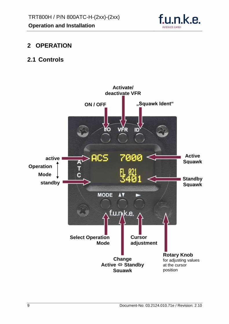
TRT800H PN 800ATC-H-(2xx)-(2xx)
Operation and Installation
10 Document-No 03212401071e Revision 210
IO ONOFF
Switch ON press button for approx 05 s
Switch OFFpress button for approx 3 s
VFR VFR
activatedeactivate VFR Squawk (press shortly)
store active Squawk as VFRVFRW-Squawk (press button 3 s rarr28)
CHANGE
change between active and standby-Squawk
works as cursor back button (opposite function of the cursor button) during entering values and also for navigating backwards through the configuration menu (rarr454)
ID IDENT
bdquoSquawk Identldquo sends Ident marking (SPI) for 18 s (rarr 29)
Enter Flight-ID (FID) setup (in standby mode press button for approx 5s)
MODE MODE Select transponder operational mode (rarr 26)
CURSOR Set position of Cursor
Rotary Knob
AdjustEnter values at current cursor position select options set standby Squawk (rarr 27)
TRT800H PN 800ATC-H-(2xx)-(2xx)
Operation and Installation
11 Document-No 03212401071e Revision 210
22 Switch ONOFF
Switch ON press IO for 05 s
Switch OFF press IO for 3 s
221 Display information after power up
After turning-on the display appears as follows (example)
If more than one configuration record is programmed the record selection menu appears (example)
Select the desired record (rotary switch) and confirm with MODE
If no external memory is connected or no 24bit address is defined the message ldquoCRADLE OFFrdquo appears In this case the device is working as ldquoMode AC onlyrdquo transponder
The transponder starts in STBY mode
2000 FL 030
STBY 7000
Cradle OFF
24D5F2 lt 000000 BE2343 000000 D4B3AA 000000 000000 000000
TRT800H V53
FPGA-Vers 102
Device Name
Software Version
Firmware Version
TRT800H PN 800ATC-H-(2xx)-(2xx)
Operation and Installation
12 Document-No 03212401071e Revision 210
23 Display - Indications
Value Meaning Remarks
7000 active Squawk
2000 Standby Squawk Could be changed with active Squawk by pressing
FL 030
FLerr
Flight Level
Invalid altitude measuring
Flight Level (in 100 ft steps)
Beyond -1000 35 000 ft C Mode gets inactive
ACS Operational Mode (STBY A-S ACS AC A)
Modes see section 26
IDT transmits Ident-Marking (SPI) ID (bdquoSquawk Identldquo) has been pressed ndash active for 18 s
Transponder replies
on Mode-S Mode-A or Mode-C interrogations
No indication on ADSB and squitter transmission
| Transponder is locked by a ground station and will be directly addressed
Lock Information (indicated below the diamond)
F
G
in-flight
on-ground
Ground-Switch-Info
(if installedavailable)
ACS
7000
TM
PLLTRX DC | BATDIM
IDT FL 030
STBY 2000 F
Passive Squawk
Active Squawk
Test mode indicatior
GND switch status
Operational Mode Standby
SPI indicator
Error indications
Reply indication
Lock out indication
Flight level
Backlight setup
Low battery ind
Operational Mode Active
TRT800H PN 800ATC-H-(2xx)-(2xx)
Operation and Installation
13 Document-No 03212401071e Revision 210
Value Meaning Remarks
Error indicators
PLL PLL Error Internal Error
TRX Transmit Failure Check antenna and wiring
DC Low internal voltage Internal error
FPG FPGA-Failure Internal error
BAT Battery Power too low maybe batterygenerator fault
24 Display-Brightness
In active mode (not standby) press for 2 s
Display indicates ldquoDIMrdquo Adjust brightness (DIM) with rotary knob
Return to normal operation press or wait 5 s
25 Flight-ID (FID)
The FID is an identifier required for Mode S Operation During future application of flight plans a FID could be assigned on a per flight basis If no FID is assigned (todayrsquos normal case) the registration marking of the aircraft should be used as FID The FID should not contain dashes or blanks The FID must not be confused with the 24-bit Aircraft Address
251 Display Flight-ID
Press MODE (repeatedly) until bdquoSTBYldquo appears
Press and hold ID while a counter is shown beside the active squawk During a few seconds Flight Identification is displayed
FID 02
A B C D E F G H
-
TRT800H PN 800ATC-H-(2xx)-(2xx)
Operation and Installation
14 Document-No 03212401071e Revision 210
252 Configure Flight-ID
Press MODE (repeatedly) until bdquoSTBYldquo appears
Press and hold ID while a counter is shown beside the active squawk Release ID when ldquoCHANGE FIDrdquo is displayed
Enter Flight-Id with cursor button and rotary knob
Press MODE to save and return to STBY
Please refer to section 454 for configuration of the 24-bit Address (AA) and Aircraft Category (AC)
26 Transponder Mode selection
Press MODE (repeatedly) to select from following Modes
STBY bdquoStandbyldquo Transponder does not respond to any interrogation Squitter and ADS-B output is not active
A C S bdquoMode A+C+Sldquo Standard condition transponder responds to mode A C and S interrogations
A ndash S bdquoMode A+S no Cldquo Altitude is not transmitted (neither on C nor on S requests) All other Mode-S data as well as Mode-A replies are transmitted
Enter FID left-aligned without any blanks or dashes () eg 12345621DEFAV for the marking D-EFAV The last remaining digits shall be filled with blanks
CHANGE FID
_ _ _ _ _ _ _ _ A B C D E F G H
- exit
TRT800H PN 800ATC-H-(2xx)-(2xx)
Operation and Installation
15 Document-No 03212401071e Revision 210
If no 24-bit address (AA) was defined or entered as ldquo000000ldquo the transponder operates as a Mode AC transponder in that case the following Modes are possible apart from Standby
A C ndash bdquoMode A+Cldquo Transponder replies only on Mode A and Mode-C interrogations
A ndash ndash bdquoMode Aldquo Transponder replies only on Mode A interrogations
In STBY (Standby) mode all transponder transmissions are disabled completely Therefore the transponder is not visible in this mode to air traffic control or the anti-collision systems onboard other aircrafts
Never use the STBY mode in flight unless you are requested to do so by air traffic control Always remember to put the transponder in active mode prior to take off
27 Squawk-Setting
The active Squawk is displayed in the upper line while the standby Squawk is presented at the lower line
Setting the Standby Squawk
Press to set the cursor (bdquo^ldquo) turn rotary knob to set numbers of the standby Squawk
Press to activate the Standby Squawk (this moves the current active Squawk into Standby)
28 VFR ndash Squawk
The transponder features a user-defined squawk code for VFR-flight (factory setting 7000)
Activate VFR-Squawk
Press VFR (bdquoVFRldquo is indicated) now the active Squawk is moved into Standby but not visible because the indication of the Standby Squawk is overlapped by bdquoVFRldquo
TRT800H PN 800ATC-H-(2xx)-(2xx)
Operation and Installation
16 Document-No 03212401071e Revision 210
Display Standby Squawk
Press VFR or or use the rotary knob (the VFR-Squawk remains active)
Example
VFR VFR
Now the Standby Squawk can be adjusted by using the rotary knob and activated with
In order to store the current active Squawk as new VFR-Squawk (replacing the factory setting 7000) Press and hold VFR until an bdquoSldquo is indicated (approx 3 s) after releasing the button bdquoVFRldquo is shown
29 ID ndash Special Position Identification (SPI) ldquoSquawk Identrdquo
Press ID to activate transmission of the special position identification pulse with every reply within 18 seconds ldquoIDTrdquo appears on the display
By pressing ID a special position identification pulse (SPI) is transmitted with every reply within 18 seconds which causes an accented marking on the Controllerrsquos screen The bdquoSpecial Position Identificationldquo has to be activated after the bdquoSquawk Identldquo request of the Controller
210 Error-Codes
Please refer to 23 Display - Indications for possible displayed errors
7000
FL 030
STBY 4700
7000
FL 030
STBY VFR
4700
FL 030
STBY 5600
TRT800H PN 800ATC-H-(2xx)-(2xx)
Operation and Installation
17 Document-No 03212401071e Revision 210
3 INSTALLATION
31 Notes
The following suggestions should be considered before installing
The assigned installation company will supply wiring For diagrams refer to 37 Wiring
Transponder External Memory all cables and antennas shall be installed according to bdquoFAA AC-14313-2A Acceptable Methods Techniques and Practices ndash Aircraft Alterationsldquo and the appropriate manufacturerrsquos instructions
32 Telecommunication data
Depending on your national telecommunications legislation the following data may be required when applying for the aircraft radio station license
Manufacturer funke AVIONICS GmbH
Type Designation TRT800H
EASA Number EASA21O269
Transmitter Power Output
126 W
Frequency 1090 MHz
Emission Designator 12M0M1D
33 Scope of Delivery
Item namenumber Description
TRT800H Transponder TRT800H
TRT800EMSS External Memory (Aircraft-Address-Adaptor with wiring)
M4X8ZSW (3 pieces) screw for panels up to 5 mm thickness
56S101A4 TNC antenna connector
03212401071e Manual bdquoOperation and Installationldquo
EASA Form 1
TRT800H PN 800ATC-H-(2xx)-(2xx)
Operation and Installation
18 Document-No 03212401071e Revision 210
34 Unpacking and Inspecting of the Equipment
Carefully unpack the equipment and inspect for transport damages If a damage claim has to be filed save the shipping container and all packing materials as evidence to your claim
35 Mounting
In cooperation with a maintenance shop location and kind of the installation are specified The maintenance shop can supply all cables Suitable sets of cables are available from funke AVIONICS GmbH
Select a position away from heat sources Provide space for adequate convection cooling
Leave sufficient space for the installation of cables and connectors
Avoid sharp bends and wiring close to control cables
Leave sufficient lead length for inspection or repair of the wiring of the connector (containing the memory) so that when the mounting hardware for the rear connectors is removed the assembly may be pulled forward several inches
Bend the harness at the rear connectors to inhibit water droplets (formed due to condensation) from collecting in the connector
For mounting detailsdrawing refer to chapter 3122 Mounting Advices
For storage or reshipment the original packaging should be used
TRT800H PN 800ATC-H-(2xx)-(2xx)
Operation and Installation
19 Document-No 03212401071e Revision 210
36 Equipment Connections
361 Electrical Connections
One 15 pin D-SUB miniature connector includes all electrical connections except for the antenna Use only an External Memory Adapter TRT800EMxx as this is part of the certification and includes a memory device in which the ICAO 24-bit Aircraft Address is stored
3611 Mutual Suppression
Other equipment on board (e g DME) may transmit in the same frequency band as the transponder
If such a device is installed a suppression wiring shall be installed in order to protect the receiving parts of the different devices from in-band transmissions
Mutual suppression is a synchronous pulse that is sent to the other equipment to suppress transmission of a competing transmitter for the duration of the pulse train transmission The transponder transmission may be suppressed by an external source and vice versa
To activate mutual suppression connect the SUPP_IO signal to the according signals of the other equipment
3612 Ground Switch
If an external Ground-Switch is connected to the transponder and activated in the setup the transponder can detect if the aircraft is airborne or on the ground This allows the transponder to automatically activate the Ground mode whenever the aircraft is on ground
In order to activate this feature the input bdquoFLY-GNDldquo must be connected to an external switch which connects the input pin with bdquoGNDldquo when the gear is weighted or remains open in the other case
This feature must additionally be activated in the Setup For details on configuration please refer to section 454
The (+UB)-wire has to protected by circuit breaker (2 Amp)
TRT800H PN 800ATC-H-(2xx)-(2xx)
Operation and Installation
20 Document-No 03212401071e Revision 210
3613 Auto-On
The Auto-On input allows to define how the transponder will behave when power is supplied to it
If the aircraft is equipped with a dedicated avionics master switch that switches the power supply to the transponder the pin Auto-On must be wired together with the UB+ pin to the avionic master switch The onoff button on the transponder is without function in that case The transponder will start automatically whenever power is supplied
On aircraft without such an avionics master switch the pin Auto-On must be left unconnected In this case the transponder must be switched on and off via the transponders onoff button on the front panel
362 Static Air Port
Install a silicon soft tube fitting the 5 mm static air hose at the backside of the transponder and secure plumbing with appropriate clamps
37 Wiring
371 Conductor Cross Section
Power Supply (Power GND) AWG20 (062 mmsup2)
Signals AWG22 (038 mmsup2)
The conductors must be approved for aircraft use
TRT800H PN 800ATC-H-(2xx)-(2xx)
Operation and Installation
21 Document-No 03212401071e Revision 210
372 Pin Assignment
The transponder may only be operated together with an external memory address adaptor TRT800EMxx
Pin Signal Remarks Adaptor
Typ(4)
TRT800
EM
Adaptor
Typ(4)
TRT800
EMSS
Adaptor Typ
TRT800
EMRS
1 GND -
2 Remote control(1) Input
3 EEPROM Signal TRT800EMxx internal
4 EEPROM Signal TRT800EMxx internal
5 TX RS-232 Serial Output
6 Switched +UB(1) Output
7 Remote control(1) Output
8 +UB power supply Input
9 GND -
10 EEPROM VCC TRT800EMxx internal
11 EEPROM GND TRT800EMxx internal
12 RX RS-232 Serial Input
13 Suppression Input Output
14 Auto-On(2) Input(2)
15 Fly-GND Switch(3) Input(3)
= in the plug and get out = in the plug and not get out ∕ = internal connection to the device
(1) SWITCHED +UB OUT Interface Remote control
May only be used for compatible funke AVIONICS devices Do not connect pins if interface is not used
(2) Auto-On Connect to +UB override front panel onoff button Leave unconnected to use front panel onoff button
(3) Ground Switch
FLY-GND
If an external Ground Switch is connected it must connect this pin to GND to indicate the on-ground condition Leave open otherwise
(4) Adaptors TRT800EM amp TRT800EMSS
Adaptor version does not provide full interface capability (see table for details)
TRT800H PN 800ATC-H-(2xx)-(2xx)
Operation and Installation
22 Document-No 03212401071e Revision 210
373 Cable plan External Memory EM800
3731 Cable plan TRT800EMRS (older version with interface remote)
to SN 90932013
DSUB 15pol
TRT800HTRT800A
lt PIN-5 gt
lt PIN-12gt
lt PIN-15gt
lt PIN-13gt
lt PIN-7 gt
lt PIN-2 gt
lt PIN-6 gt
lt PIN-1 gt
lt PIN-9 gt
lt PIN-8 gt
lt PIN-14gt
TXD
RXD
FLY_GND
SUPP_IO
GND
open
cable
ends
Remote Binder
Connector
female
white
black
yellow
red
shield
blue
red
brown
GND
+UB
AUTO-ON(2)(3)
black
white
red
yellow
shield
Binder Connector female
(solder side)
1 2 3 4 5 6 7 8
9 10 11 12 13 14 15
D-SUB Connector female
(solder side)
open
cable
ends
1 New interface available
-at TRT800H starting from SN 30430109 with SW V53
-at TRT800A starting with SW V53 2 New TRT800H interface starting from HW 60 3 port function not available at TRT800A
3
4 2
5 1
RMT-LIGHT
GND
RMT-TXD
RMT-SW+UB
RMT-RXD
RMT-TXD(1)
RMT-RXD(1)
RMT-SW+UB(2)(3)
RMT-LIGHT(2)
GND(1)
TRT800H PN 800ATC-H-(2xx)-(2xx)
Operation and Installation
23 Document-No 03212401071e Revision 210
3732 Cable plan TRT800EMRS (newer version with interface remote)
from SN 90932114
DSUB 15pol
TRT800HTRT800A
lt PIN-5 gt
lt PIN-12gt
lt PIN-15gt
lt PIN-13gt
lt PIN-7 gt
lt PIN-2 gt
lt PIN-6 gt
lt PIN-1 gt
lt PIN-9 gt
lt PIN-8 gt
lt PIN-14gt
TXD
RXD
FLY_GND
SUPP_IO
GND
open
cable
ends
Remote Binder
Connector
female
white
brown
yellow
green
shield
blue
red
brown
GND
+UB
AUTO-ON(2)(3)
brown
white
green
yellow
shield
Binder Connector female
(solder side)
1 2 3 4 5 6 7 8
9 10 11 12 13 14 15
D-SUB Connector female
(solder side)
open
cable
ends
1 New interface available
-at TRT800H starting from SN 30430109 with SW V53
-at TRT800A starting with SW V53 2 New TRT800H interface starting from HW 60 3 port function not available at TRT800A
3
4 2
5 1
RMT-LIGHT
GND
RMT-TXD
RMT-SW+UB
RMT-RXD
RMT-TXD(1)
RMT-RXD(1)
RMT-SW+UB(2)(3)
RMT-LIGHT(2)
GND(1)
TRT800H PN 800ATC-H-(2xx)-(2xx)
Operation and Installation
24 Document-No 03212401071e Revision 210
3733 Cable plan TRT800EMSS (newer version without interface remote)
from SN 91032115
The External ndash Memory ndash Address - Adapter TRT800EMxx contains electronic parts and must not be opened Opening or modifying the connector leads to the loss of airworthiness certification
DSUB 15pol
TRT800HTRT800A
lt PIN-5 gt
lt PIN-12gt
lt PIN-15gt
lt PIN-13gt
lt PIN-1 gt
lt PIN-9 gt
lt PIN-8 gt
lt PIN-14gt
TXD
RXD
FLY_GND
SUPP_IO
GND
open
cable
ends
white
brown
yellow
green
shield
blue
red
brown
GND
+UB
AUTO-ON(2)(3)
open
cable
ends
2 New TRT800H interface starting from HW 60 3 port function not available at TRT800A
1 2 3 4 5 6 7 8
9 10 11 12 13 14 15
D-SUB Connector female
(solder side)
TRT800H PN 800ATC-H-(2xx)-(2xx)
Operation and Installation
25 Document-No 03212401071e Revision 210
38 Antenna
381 Antenna Selection
Recommended antennas see section 311 Accessories
Choose an antenna type compatible with the vehicle and the mounting location
Specified features depend on proper installation of the antenna
The radiation pattern needs to be verified considering aircraft type and mounting location
The electrical interference between the antenna and any other equipment must be taken into account in such a way that no reduction of the performance of any other system will occur
Install only certified antennas
382 Installation Recommendation
Take note of the antenna manufacturerrsquos instructions
The usually deployed Dipole- or Blade antennas necessarily require a high frequency capable solid metal ground plane at the antenna base
For installation in composite aircrafts ground planes are to be added The ground plane should be as large as possible but in any case not smaller than 10 cm x 10 cm If in doubt please contact the aircraft manufacturer
Keep away three feet from any other antenna
Pursue mounting in vertical position under the belly in flight direction
383 Antenna Wiring
Suitable antenna cables see section 311 Accessories
Keep wiring as short as possible
The smallest cable bend radius is 10cm Avoid sharp bends
Keep away from an ADF antenna cable at least 12 inches
Electrical connections to the antenna shall be protected against moisture to avoid loss of efficiency
TRT800H PN 800ATC-H-(2xx)-(2xx)
Operation and Installation
26 Document-No 03212401071e Revision 210
39 Post-Installation Check
All steering and control functions of the aircraft are to be examined in order to exclude disturbances by the wiring
The most important factor in the transponder configuration is the setting of the ICAO address (see section 454)
Attenuation from antenna to transponder at 1090 MHz must not exceed 15 dB
A certified maintenance shop must verify proper operation of the transponder by testing in accordance with Appendix F of ldquo14 CFR Part 43 ndash ATC Transponder Tests and Inspectionsrdquo
TRT800H PN 800ATC-H-(2xx)-(2xx)
Operation and Installation
27 Document-No 03212401071e Revision 210
310 Starting Up
Turn the transponder on with IO After start-up the following screens appear
311 Accessories
Part Number Description
TRKABEL1 Antenna cable 10 m (32 ft) TNC BNC
TRKABEL2 Antenna cable 25 m (82 ft) TNC BNC
TRKABEL3 Antenna cable 40 m (132 ft) TNC BNC
TRKABEL4 Antenna cable 65 m (213 ft) TNC BNC
TRT800EMRS External-Memory (Aircraft-Address-Adaptor) Connection cable with interface TRT-Remote control
CI-105 TransponderDME Antenna TSO C66b C74c
CI105 Comant Industries Inc
Height 325rdquo Weight 90 g (02 lbs)
AV22 Transponder Rod antenna TSO C74c
AV-22 R A Miller Industries
The TRT800H starts in standby mode (indicated with STBY) In order to change into operational mode (indicated with ACS) press MODE If ground switch is connected and status ldquoin flightrdquo is selected TRT800H starts in active mode
Very important is the correct configuration of the 24bit Aircraft-Address (see 454 General Setup)
TRT800H V53
FPGA-Vers 102
2000 FL 030
STBY 7000
TRT800H PN 800ATC-H-(2xx)-(2xx)
Operation and Installation
28 Document-No 03212401071e Revision 210
312 Drawings
3121 Dimensions
20mm15 mm
170 mm
TRT800TRT800H
65 mm
65
mm
Oslash 57 mm
Static Air
Antenna
PowerRS232
3122 Mounting Advices
Connections Area
8
0 m
m
Panel Cut-out
470 mm
470
mm
575 mm
4 x Oslash 4 mm
Oslash
Connector (plug) has to be clamped with both spring locks
No screws may be turned in more than max 15mm into the device ndash even if no hard limit is noticeable
Fixing clips (spring) left right
TRT800H PN 800ATC-H-(2xx)-(2xx)
Operation and Installation
29 Document-No 03212401071e Revision 210
4 TRANSPONDER SETTINGS
41 Overview
The TRT800H is capable of storing the following information
ICAO 24-Bit Aircraft-Address (AA)
Aircraft Category (AC)
Flight Identification (FID)
Ground-Switch (YesNo)
Speed Category (RI)
RS232 Interface Configuration
All of these data are configurable in the Setup and are stored in the external memory module integrated within the housing of the D-Sub connector (included in the delivery)
The cable with this connector shall remain in the aircraft even if the unit is removed to ensure that the ICAO 24bit aircraft address is fixed to the aircraft
Additionally the following usertransponder related settings are stored transponder internally
Active Squawk
Passive Squawk
VFR Squawk
Altitude offset
Display brightness
42 Display Configuration Summary
Transponder provides the opportunity to show summary of complete current settings To access configuration summary pages push and hold
ID in Standby mode Release ID if ldquoSHOW SETUPrdquo is displayed The summary is subdivided into the following pages
TRT800H PN 800ATC-H-(2xx)-(2xx)
Operation and Installation
30 Document-No 03212401071e Revision 210
Page 1
Aircraft Address
Aircraft Category
Flight Identification
MODE
Page 2 Speed Category
Ground Switch option
Remote Header option
MODE
Page 3 RS-232 Settings
Protocol baud rate position (if available)1
MODE
Page 4 Altitude correction settings
(part 1)
MODE
Page 5 Altitude correction settings
(part 2)
Note 1 Position data will only be displayed if
a GPS protocol is set as interface protocol (NMEA FREEFLIGHT AR-NAV)
18000 ft 0ft 25000 ft + 100ft 35000 ft - 50ft
exit
ALTITUDE CORRECTION 2000 ft 0ft 10000 ft + 100ft next
RS-232 NMEA Baud 4800 Pos 481 99 next
Speed Cat 8 Ground Sw YES Remote Hd NO next
AA F E 1 2 3 4 AC 1 9 FID 4 4 E 1 2 3 next
TRT800H PN 800ATC-H-(2xx)-(2xx)
Operation and Installation
31 Document-No 03212401071e Revision 210
GPS receiver is connected and transmits data (if not ldquoPos no datardquo is displayed)
a valid position is transmitted (if not ldquoPos wrong datardquo is displayed)
While configuration summary page is displayed no new position data will be processed
43 General settings
431 ICAO 24-Bit Aircraft Address (AA)
Ask your national aviation authority (e g in Germany LBA Referat B5 Department ldquoVerkehrszulassungrdquo) how to obtain the AA In the case of aerial sports equipment the contact point would be the respective associations Only the assigned AA has to be used and must not be modified at any time because a duplicate address would jeopardize the data surveillance and integrity figures of Mode S
If no AA is stored after power on the display shows ldquoCRADLE OFFrdquo and the transponder operates in Mode AC
(Configuration of the AA see section 454)
432 Aircraft Category (AC)
Code Description Code Description
11 Emergency Vehicle 1C Ultra-Light Paraglider
12 Service Vehicle 1E Drone
19 Glider 21 Aircraft (D-Exxx) lt 15500 lbs Motor Glider (D-Kxxx)
1A Balloon amp Airship 22 Aircraft ge 15500 lbslt 75000 lbs
1B Paratrooper 27 Rotorcraft
Only one of the Codes mentioned in the table above must be used
Setuprarr454
Setuprarr454
TRT800H PN 800ATC-H-(2xx)-(2xx)
Operation and Installation
32 Document-No 03212401071e Revision 210
433 Flight-ID (FID)
Per ICAO regulation Mode-S data must contain a valid flight identification (FID) to ensure that the correlation between flight plan and radar data will work automatically
FID setting is required to correspond to the aircraft identification that has been specified at item 7 of the ICAO flight plan It contains seven characters at a maximum (left-aligned no additional zeros dashes or spacesblanks)
For an aircraft using a company call sign the Flight-ID mostly consists of the ICAO three-letter designator for the aircraft operator followed by an identification code eg KLM511 BAW213 JTR25
If no company call sign is used or no flight plan is filed the default FID to be set consists of the registration marking of the aircraft (eg DEABC) with no dashes spacesblanks or additional zeros even if they are included in the registration marking on the aircraft (tail number) While entering the FID into the transponder the last remaining digits must be filled with blanks
The ICAO Flight Plan only specifies 7 characters for FID funke AVIONICS reserves 8 characters as stated in ED-73B for further expansion of the flight plan
The user shall only program 7 characters for FID
Setuprarr454
TRT800H PN 800ATC-H-(2xx)-(2xx)
Operation and Installation
33 Document-No 03212401071e Revision 210
434 Reply Information - Speed Category (RI)
Besides AA AC and FID another important part of the Mode-S data is the Speed Category of the respective aircraft This speed category shall be configured in the setup and must contain one of the following codes
Code Description
08 No maximum airspeed data available
09 Maximum airspeed le 75 kt
10 75 kt gt maximum airspeed le 150 kt
11 150 kt gt maximum airspeed le 300 kt
12 300 kt gt maximum airspeed le 600 kt
13 600 kt gt maximum airspeed le 1200 kt
14 Maximum airspeed gt 1200 kt
15 Not assigned
44 Optional settings
441 Option Ground-Switch
If a ground switch is connected (and enabled in setup) the transponder is able to determine on-ground and in-flight state On-ground state is activated automatically once the gear touches the ground On-ground state is indicated on display by symbol G (apart from lsquoFrsquo for In-flight-state)
In On-ground-state the transponder will reply differently to certain addressed interrogations Also the transmission rate of some periodically sent data (squitters ADS-B) is reduced This allows ATC to distinguish between airborne aircraft and those on the ground and it reduces the Mode S channel load
For small aircraft authorities normally do not require such a ground switch In this case the transponder will use the same data formats on the ground as in the airborne state
Setuprarr454 Wiringrarr373
Setuprarr454
TRT800H PN 800ATC-H-(2xx)-(2xx)
Operation and Installation
34 Document-No 03212401071e Revision 210
442 Option Remote Header
The transponder provides a TRT800RT remote control interface If a remote header TRT800RT is connected transponder can be remote controlled via this interface Remote interface provides control of all standard user inputs available during standard operational mode For more information see TRT800RT manual Remote control interface de-activation is setup configurable Remote control interface must only be connected to TRT800RT
443 Serial Interface (RS232)
Using serial interface a GPS receiver can be connected to broadcast own position via ADS-B Out position message Position could be received by other appropriately equipped aircrafts and processed for collision avoidance ADS-B Out functionality
The ADS-B function of this device has not been evaluated during the FAA TSO certification process other than to ensure non-interference Due to the SW assurance of DAL D the ADS-B function cannot be used in the US National Airspace Connecting a GPS source will not comply to FAA certification requirements with regard to ADS-B
Supported formatsprotocols are
Option Description Baud rate
FREEFLIGHT GPSWAAS Sensor 1201
NexNav NNL 3101
19200
AR-NAV Bendix King
KLN 89B KLN 94 ldquoStandard RS232 Sentencerdquo
KMD 150 ldquoSentence Type 1rdquo
Garmin 400 Series ldquoSentence Type 1rdquo (with and without altitude data)
9600
NMEA NMEA-Format data format RMC is expected
4800
Setuprarr454 Wiringrarr373
Setuprarr454 Wiringrarr373
TRT800H PN 800ATC-H-(2xx)-(2xx)
Operation and Installation
35 Document-No 03212401071e Revision 210
Option Description Baud rate
FAVISIA Glass Cockpit support
FAVISIA Data format to be processed in FAVISIA avionics suite
-
FAVISIA+GPS Data format to be processed in FAVISIA avionics suite (output) and additional processing of incoming NMEA GPS-Receiver position data to support the ADS-B Out functionality
4800
Other
Comm-AB-support
Data format for special purpose An additional data link processor allows COMM-AB operation and processing of the position information of a flight management system simultaneously
38400
Disabled No communication via RS232 interface -
444 Altitude CorrectionOffset
The TRT800H has an integrated temperature compensated high-precision pressure sensor This sensor is factory-calibrated so that it will yield accurate flight level (uncorrected pressure altitude) within the entire altitude range
However due to differences in calibration of the TRT800H pressure sensor and the altimeter in the cockpit it may become necessary to adjust the TRT800H pressure readings so that the value indicated and transmitted by the TRT800H corresponds to the indication of the primary altimeter seen by the pilot within 125 feet (as specified in ETSO C88aSAE AS 8003)
Setting for all described GPS-systems
1 2 position messages per 2 sec
Setuprarr455
TRT800H PN 800ATC-H-(2xx)-(2xx)
Operation and Installation
36 Document-No 03212401071e Revision 210
The check for correspondence between the primary altimeter and the TRT800H is usually performed every 24 months as part of the aircrafts altimeter checks
Altitude correction is based on setup configurable offset values at five interpolation points ( 2000 8000 18000 25000 and 35000 ft)The offset value itself is limited to a range from -100 to + 100ft at each point (10ft steps)
45 Setup Procedure
Programming of the ICAOA 24-bit Aircraft Address and of the Aircraft Category shall be executed by qualified personnel only
A wrong Aircraft Address or Flight ID may cause serious problems ATC or with ACASTCAS systems
Pilot and owner are responsible for correctly set transponder data
451 Setup Menu Control
In order to access the functions described in the following paragraphs push and hold ID in Standby mode Release ID if desired counter value menu name is displayed to enter the menu The following menu entries are selectable
Count Displayed Name Function
03 FID FID is displayed
48 CHANGE FID Enter FID setup page
913 SHOW SETUP Enter setup summary listed on different pages (no changes possible)
2528 ENTER SETUP Enter transponder general configuration pages
3134 ALTITUDE CORRECTION
Enter altitude correction menu
TRT800H PN 800ATC-H-(2xx)-(2xx)
Operation and Installation
37 Document-No 03212401071e Revision 210
452 Transponder configurationrecord structure
Aircraft related parts of transponder configuration are stored in one out of eight possible records (record=presetting) Each record contains the following information
Aircraft Address (AA 24bit)
Aircraft category (AC)
Flight identification (FID 6-8 numbersletters)
RS-232 Interface setting (eg GPS protocol)
Ground-Switch setting (Installed YesNo)
Speed category (RI) of the respective aircraft
Remote Header setting (Installed YesNo)
User related settings (eg squawk codes display brightness) are stored once in one global record (transponder internally)
453 Transponder configurationrecord handling
At least one record is stored in external memory Up to 8 records can be additional be applied during setup process
If more than one record is applied the active record must be selected out of a list (determined by FID) during start-up of the transponder
Previously applied records can be deleted again by filling FID with zerorsquos only
454 General Setup
Any menu item can be passed by MODE If no changes are made the original settings will remain stored Modification of one menu item does not impact the others No entries will be deleted
TRT800H PN 800ATC-H-(2xx)-(2xx)
Operation and Installation
38 Document-No 03212401071e Revision 210
Step Display (Example)
1 Start-up Transponder
2 Ensure the transponder-mode is bdquoSTBYldquo If necessary change the mode by pressing MODE
3 Press ID A counter is shown at the upper-right corner Hold ID till ldquoENTER SETUPrdquo is displayed
4 After release of ID the first setup menu is displayed
5 helliphellipselect position (^)
rotary knobchange value
MODE
6 With the rotary knob you can select bdquoyesldquo if a Ground Switch is installed if not select ldquonordquo and proceed with step 7
MODE
Record 1
GND Switch YesNo
next
AA EF123456
AC 18
FID ^BCDEFG
next
AA EF123456
AC 18
FID ABCDEFG
next
ENTER SETUP 26
2000 FL 030
STBY 7000
TRT800H PN 800ATC-H-(2xx)-(2xx)
Operation and Installation
39 Document-No 03212401071e Revision 210
Step Display (Example)
7 At this stage the respective speed category shall be selected by using the rotary knob
MODE
8 At this stage a GPS receiver for ADS-B Out can be selected (Selectable by rotary knob)
MODE
9 At this stage remote interface for communication between TRT800H and remote header can be activated (Selectable by rotary knob)
Remote interface must only be activated if a remote header is connected
MODE
10 With ID further Records can now be created and configured as described in the aforementioned steps At start-up of the transponder one of the defined records with all associated configurations need to be selected
MODE
Records ID=Edit Records
EXIT
Record 1
REMOTE Header YesNo
next
Record 1
GPSINTEXT NMEA
next
Record 1
Speed Cat 08-15
next
TRT800H PN 800ATC-H-(2xx)-(2xx)
Operation and Installation
40 Document-No 03212401071e Revision 210
Step Display (Example)
11 You have now left the configuration mode and are back in normal operation
12 Switch off the transponder
13 Switch on the transponder Your ICAO 24-Bit Aircraft Address is now stored
TRT800H V53
FPGA-Vers 102
2000 FL 030
STBY 7000
TRT800H PN 800ATC-H-(2xx)-(2xx)
Operation and Installation
41 Document-No 03212401071e Revision 210
455 Altitude Correction Setup
Altitude correction setup shall be executed by qualified personnel only
Pilot and owner are responsible for correctly set altitude offset values
The usesetting of altitude correction values is only necessary in exceptional cases (see 444 for details)
Altitude correction is based on five interpolation points ( 2000 10000 18000 25000 and 35000 ft)The offset value at each interpolation point can be adjusted in a range from -100 to + 100ft at each point (10ft steps) Offset values set to zero at each interpolation point deactivates altitude correction (defaultfactory setting)
Step Display (Example)
1 Start-up Transponder
2 Ensure the transponder-mode is bdquoSTBYldquo If necessary change the mode by pressing MODE
3 Press ID A counter is shown at the upper-right corner Hold ID till ldquoALTITUDE OFFSETrdquo is displayed
ALTITUDE OFFSET 33
2000 FL 030
STBY 7000
Descriptionrarr444
TRT800H PN 800ATC-H-(2xx)-(2xx)
Operation and Installation
42 Document-No 03212401071e Revision 210
Step Display (Example)
4 After release of ID the first altitude level + corresponding offset value is displayed
5 Change offset value with rotary knob
MODE
6 (9) Repeat last step for another 4 altitude levels 10000ft 18000ft 25000ft 35000ft
MODE
10 You have now left the configuration mode and are back in normal operation
Switch off the transponder
11 Switch on the transponder New altitude offset values will now be used for altitude calculation
Altitude 10000 ft
Offset 0 ft
nextexit
Altitude 2000 ft
Offset 0 ft
next
TRT800H V53
FPGA-Vers 102
2000 FL 030
STBY 7000
Altitude 2000 ft
Offset 0 ft
next
TRT800H PN 800ATC-H-(2xx)-(2xx)
Operation and Installation
43 Document-No 03212401071e Revision 210
5 APPENDIX
51 Technical Data
Compliance CS-ETSO-2C112a
EASA21O269
FAA TSO-C112c
Applicable Documents CS-ETSO-2C112a
FAA TSO-C112c
EUROCAE ED-73C Class 1 Level 2es
RTCA DO-181D Class 1 Level 2es
EUROCAE ED-26
RTCA DO-160D
RTCA DO-178B Software-Level D
Temperature Ranges
Operation -20 degC to +55 degC for 30 min +70degC
Storage -55 degC to +85 degC
Altitude Range le 35 000 ft
Speed Range le 250 kt (TAS)
Shock 6 G Operation
20 G crash safety
Environmental Categories RTCA DO-160D EnvCat [C1Z]CAA[SM]XXXXXXZBAAA[TT]M[B3F3]XXA
Power Supply 138 VDC (10 VDC 16 VDC)
040 A 138 VDC (typ)
070 A 138 VDC (max)
10 W (max)
TRT800H PN 800ATC-H-(2xx)-(2xx)
Operation and Installation
44 Document-No 03212401071e Revision 210
Fuse External 2A-slow-blow fuse
Mounting Panel cut-out d=575 mm
Weight 06 kg (132 lbs)
Receiver Characteristics
Sensitivity
RF input power level resulting in a 90 reply rate
A MTL for ATCRBS and ATCRBSMode S All-Call interrogations -74 dBm plusmn3 dB
B MTL for Mode S interrogations -74 dBm plusmn 3 dB
Reply transmission frequency
1090 plusmn 1 MHz
RF Peak Power Output 21 dBW (126 W) at antenna base (with maximum cable attenuation of 15 dB)
Squitter (ADS-B) transmitted at random intervals uniformly distributed over the range from 08 to 12 seconds full self-verification of data and occurrence
Mode S Elementary Surveillance
ICAO 24-bit Aircraft Address (Hex-Code)
aircraft address as assigned by national aviation authority
FID Flight ID Flight Plan call sign or aircraft registration marking
Capability Report Reports the available data and means by which the transponder can report
Pressure Altitude Up to 35 000 ft in 25 ft increments
Flight Status in-flight on-ground
Mode S Enhanced Surveillance
Level 2es Comm-A Comm-B 56112-Bit-Messages
SI-capability
TRT800H PN 800ATC-H-(2xx)-(2xx)
Operation and Installation
45 Document-No 03212401071e Revision 210
52 Environmental Conditions
Characteristic DOndash160D Section Cat Condition
Temperature Altitude 40
C1
Low ground survival temperature
451 ndash 55degC
Low operating temperature 451 ndash 20degC
High ground survival Temperature
452 + 85degC
High Short-time Operating Temperature
452 + 70degC
High Operating Temperature 453 + 55degC
In-Flight Loss of Cooling 454 Z No auxiliary cooling required
Altitude 461 C1 35 000 ft
Temperature Variation 50 C 2degC change rate minimum per minute
Humidity 60 A
Shock 70 A
6 G operational shocks
20 G Crash Safety
Test Type R in all 6 directions
Vibration 80 S Vibration Curve M
Explosion Proofness 90 X No test required
Water Proofness 100 X No test required
Fluids Susceptibilities 110 X No test required
Sand and Dust 120 X No test required
Fungus Resistance 130 X No test required
Salt Spray 140 X No test required
Magnetic Effect 150 Z Less than 03 m
Power Input (DC) 160 B
Voltage Spike Conducted 170 A
Audio Frequency Conducted Susceptibility
180 A
TRT800H PN 800ATC-H-(2xx)-(2xx)
Operation and Installation
46 Document-No 03212401071e Revision 210
Characteristic DOndash160D Section Cat Condition
Induced Signal Susceptibility 190 A
Radio Frequency Susceptibility
200 TT
Emission of RF Energy 210 M
Lightning Induced Transient Susceptibility
220 B3F3
Lightning Direct Effects 230 X No test required
Icing 240 X No test required
Electrostatic Discharge (ESD) 250 A
53 DO-178B Open Problem Reports
There are no open problem reports for the software of this device
TRT800H PN 800ATC-H-(2xx)-(2xx)
Operation and Installation
47 Document-No 03212401071e Revision 210
Notes
f funke funke means ndash fabrication utilities network know-how engineering
funke AVIONICS GmbH Heinz-Strachowitz-Str 4
DE-86807 Buchloe Germany
phone +49-8241 80066 0
fax +49-8241 80066 99 E-mail
servicefunkeavionicsde wwwfunkeavionicsde
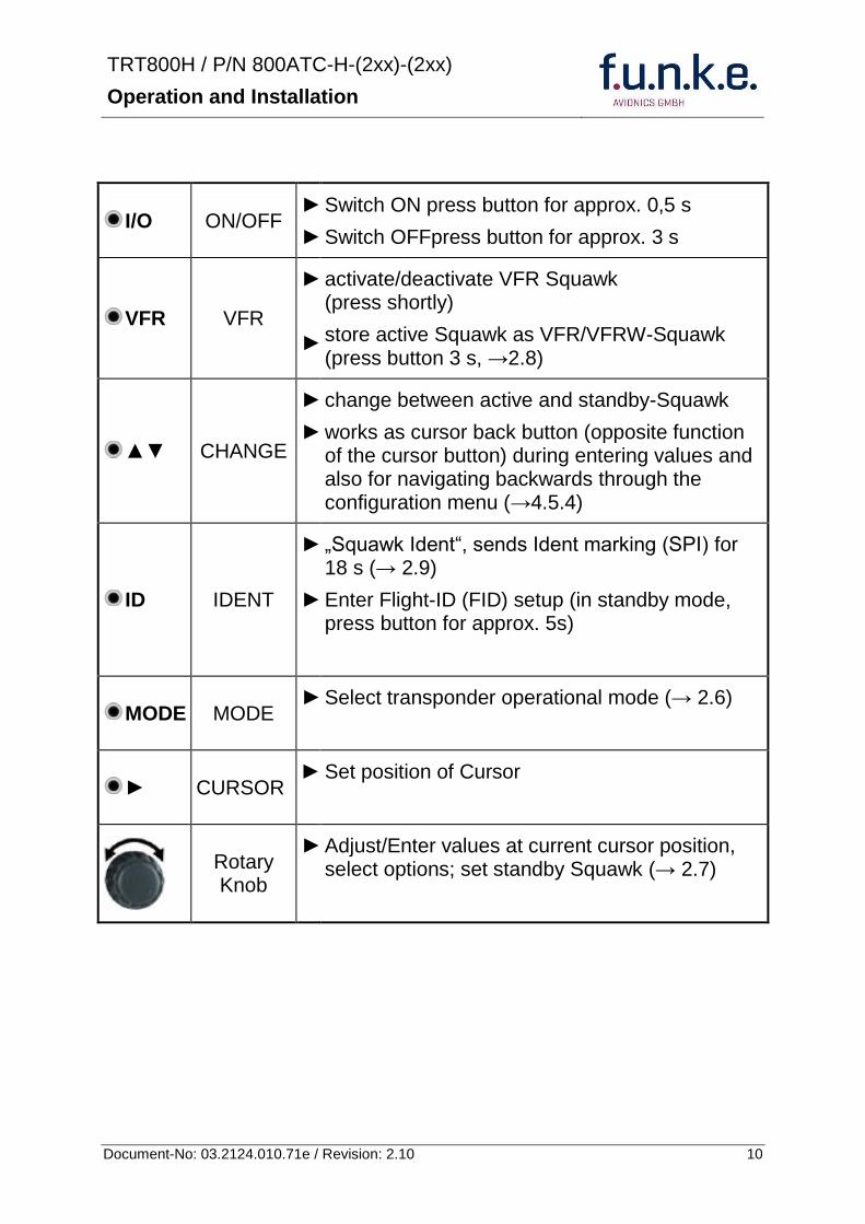
TRT800H PN 800ATC-H-(2xx)-(2xx)
Operation and Installation
11 Document-No 03212401071e Revision 210
22 Switch ONOFF
Switch ON press IO for 05 s
Switch OFF press IO for 3 s
221 Display information after power up
After turning-on the display appears as follows (example)
If more than one configuration record is programmed the record selection menu appears (example)
Select the desired record (rotary switch) and confirm with MODE
If no external memory is connected or no 24bit address is defined the message ldquoCRADLE OFFrdquo appears In this case the device is working as ldquoMode AC onlyrdquo transponder
The transponder starts in STBY mode
2000 FL 030
STBY 7000
Cradle OFF
24D5F2 lt 000000 BE2343 000000 D4B3AA 000000 000000 000000
TRT800H V53
FPGA-Vers 102
Device Name
Software Version
Firmware Version
TRT800H PN 800ATC-H-(2xx)-(2xx)
Operation and Installation
12 Document-No 03212401071e Revision 210
23 Display - Indications
Value Meaning Remarks
7000 active Squawk
2000 Standby Squawk Could be changed with active Squawk by pressing
FL 030
FLerr
Flight Level
Invalid altitude measuring
Flight Level (in 100 ft steps)
Beyond -1000 35 000 ft C Mode gets inactive
ACS Operational Mode (STBY A-S ACS AC A)
Modes see section 26
IDT transmits Ident-Marking (SPI) ID (bdquoSquawk Identldquo) has been pressed ndash active for 18 s
Transponder replies
on Mode-S Mode-A or Mode-C interrogations
No indication on ADSB and squitter transmission
| Transponder is locked by a ground station and will be directly addressed
Lock Information (indicated below the diamond)
F
G
in-flight
on-ground
Ground-Switch-Info
(if installedavailable)
ACS
7000
TM
PLLTRX DC | BATDIM
IDT FL 030
STBY 2000 F
Passive Squawk
Active Squawk
Test mode indicatior
GND switch status
Operational Mode Standby
SPI indicator
Error indications
Reply indication
Lock out indication
Flight level
Backlight setup
Low battery ind
Operational Mode Active
TRT800H PN 800ATC-H-(2xx)-(2xx)
Operation and Installation
13 Document-No 03212401071e Revision 210
Value Meaning Remarks
Error indicators
PLL PLL Error Internal Error
TRX Transmit Failure Check antenna and wiring
DC Low internal voltage Internal error
FPG FPGA-Failure Internal error
BAT Battery Power too low maybe batterygenerator fault
24 Display-Brightness
In active mode (not standby) press for 2 s
Display indicates ldquoDIMrdquo Adjust brightness (DIM) with rotary knob
Return to normal operation press or wait 5 s
25 Flight-ID (FID)
The FID is an identifier required for Mode S Operation During future application of flight plans a FID could be assigned on a per flight basis If no FID is assigned (todayrsquos normal case) the registration marking of the aircraft should be used as FID The FID should not contain dashes or blanks The FID must not be confused with the 24-bit Aircraft Address
251 Display Flight-ID
Press MODE (repeatedly) until bdquoSTBYldquo appears
Press and hold ID while a counter is shown beside the active squawk During a few seconds Flight Identification is displayed
FID 02
A B C D E F G H
-
TRT800H PN 800ATC-H-(2xx)-(2xx)
Operation and Installation
14 Document-No 03212401071e Revision 210
252 Configure Flight-ID
Press MODE (repeatedly) until bdquoSTBYldquo appears
Press and hold ID while a counter is shown beside the active squawk Release ID when ldquoCHANGE FIDrdquo is displayed
Enter Flight-Id with cursor button and rotary knob
Press MODE to save and return to STBY
Please refer to section 454 for configuration of the 24-bit Address (AA) and Aircraft Category (AC)
26 Transponder Mode selection
Press MODE (repeatedly) to select from following Modes
STBY bdquoStandbyldquo Transponder does not respond to any interrogation Squitter and ADS-B output is not active
A C S bdquoMode A+C+Sldquo Standard condition transponder responds to mode A C and S interrogations
A ndash S bdquoMode A+S no Cldquo Altitude is not transmitted (neither on C nor on S requests) All other Mode-S data as well as Mode-A replies are transmitted
Enter FID left-aligned without any blanks or dashes () eg 12345621DEFAV for the marking D-EFAV The last remaining digits shall be filled with blanks
CHANGE FID
_ _ _ _ _ _ _ _ A B C D E F G H
- exit
TRT800H PN 800ATC-H-(2xx)-(2xx)
Operation and Installation
15 Document-No 03212401071e Revision 210
If no 24-bit address (AA) was defined or entered as ldquo000000ldquo the transponder operates as a Mode AC transponder in that case the following Modes are possible apart from Standby
A C ndash bdquoMode A+Cldquo Transponder replies only on Mode A and Mode-C interrogations
A ndash ndash bdquoMode Aldquo Transponder replies only on Mode A interrogations
In STBY (Standby) mode all transponder transmissions are disabled completely Therefore the transponder is not visible in this mode to air traffic control or the anti-collision systems onboard other aircrafts
Never use the STBY mode in flight unless you are requested to do so by air traffic control Always remember to put the transponder in active mode prior to take off
27 Squawk-Setting
The active Squawk is displayed in the upper line while the standby Squawk is presented at the lower line
Setting the Standby Squawk
Press to set the cursor (bdquo^ldquo) turn rotary knob to set numbers of the standby Squawk
Press to activate the Standby Squawk (this moves the current active Squawk into Standby)
28 VFR ndash Squawk
The transponder features a user-defined squawk code for VFR-flight (factory setting 7000)
Activate VFR-Squawk
Press VFR (bdquoVFRldquo is indicated) now the active Squawk is moved into Standby but not visible because the indication of the Standby Squawk is overlapped by bdquoVFRldquo
TRT800H PN 800ATC-H-(2xx)-(2xx)
Operation and Installation
16 Document-No 03212401071e Revision 210
Display Standby Squawk
Press VFR or or use the rotary knob (the VFR-Squawk remains active)
Example
VFR VFR
Now the Standby Squawk can be adjusted by using the rotary knob and activated with
In order to store the current active Squawk as new VFR-Squawk (replacing the factory setting 7000) Press and hold VFR until an bdquoSldquo is indicated (approx 3 s) after releasing the button bdquoVFRldquo is shown
29 ID ndash Special Position Identification (SPI) ldquoSquawk Identrdquo
Press ID to activate transmission of the special position identification pulse with every reply within 18 seconds ldquoIDTrdquo appears on the display
By pressing ID a special position identification pulse (SPI) is transmitted with every reply within 18 seconds which causes an accented marking on the Controllerrsquos screen The bdquoSpecial Position Identificationldquo has to be activated after the bdquoSquawk Identldquo request of the Controller
210 Error-Codes
Please refer to 23 Display - Indications for possible displayed errors
7000
FL 030
STBY 4700
7000
FL 030
STBY VFR
4700
FL 030
STBY 5600
TRT800H PN 800ATC-H-(2xx)-(2xx)
Operation and Installation
17 Document-No 03212401071e Revision 210
3 INSTALLATION
31 Notes
The following suggestions should be considered before installing
The assigned installation company will supply wiring For diagrams refer to 37 Wiring
Transponder External Memory all cables and antennas shall be installed according to bdquoFAA AC-14313-2A Acceptable Methods Techniques and Practices ndash Aircraft Alterationsldquo and the appropriate manufacturerrsquos instructions
32 Telecommunication data
Depending on your national telecommunications legislation the following data may be required when applying for the aircraft radio station license
Manufacturer funke AVIONICS GmbH
Type Designation TRT800H
EASA Number EASA21O269
Transmitter Power Output
126 W
Frequency 1090 MHz
Emission Designator 12M0M1D
33 Scope of Delivery
Item namenumber Description
TRT800H Transponder TRT800H
TRT800EMSS External Memory (Aircraft-Address-Adaptor with wiring)
M4X8ZSW (3 pieces) screw for panels up to 5 mm thickness
56S101A4 TNC antenna connector
03212401071e Manual bdquoOperation and Installationldquo
EASA Form 1
TRT800H PN 800ATC-H-(2xx)-(2xx)
Operation and Installation
18 Document-No 03212401071e Revision 210
34 Unpacking and Inspecting of the Equipment
Carefully unpack the equipment and inspect for transport damages If a damage claim has to be filed save the shipping container and all packing materials as evidence to your claim
35 Mounting
In cooperation with a maintenance shop location and kind of the installation are specified The maintenance shop can supply all cables Suitable sets of cables are available from funke AVIONICS GmbH
Select a position away from heat sources Provide space for adequate convection cooling
Leave sufficient space for the installation of cables and connectors
Avoid sharp bends and wiring close to control cables
Leave sufficient lead length for inspection or repair of the wiring of the connector (containing the memory) so that when the mounting hardware for the rear connectors is removed the assembly may be pulled forward several inches
Bend the harness at the rear connectors to inhibit water droplets (formed due to condensation) from collecting in the connector
For mounting detailsdrawing refer to chapter 3122 Mounting Advices
For storage or reshipment the original packaging should be used
TRT800H PN 800ATC-H-(2xx)-(2xx)
Operation and Installation
19 Document-No 03212401071e Revision 210
36 Equipment Connections
361 Electrical Connections
One 15 pin D-SUB miniature connector includes all electrical connections except for the antenna Use only an External Memory Adapter TRT800EMxx as this is part of the certification and includes a memory device in which the ICAO 24-bit Aircraft Address is stored
3611 Mutual Suppression
Other equipment on board (e g DME) may transmit in the same frequency band as the transponder
If such a device is installed a suppression wiring shall be installed in order to protect the receiving parts of the different devices from in-band transmissions
Mutual suppression is a synchronous pulse that is sent to the other equipment to suppress transmission of a competing transmitter for the duration of the pulse train transmission The transponder transmission may be suppressed by an external source and vice versa
To activate mutual suppression connect the SUPP_IO signal to the according signals of the other equipment
3612 Ground Switch
If an external Ground-Switch is connected to the transponder and activated in the setup the transponder can detect if the aircraft is airborne or on the ground This allows the transponder to automatically activate the Ground mode whenever the aircraft is on ground
In order to activate this feature the input bdquoFLY-GNDldquo must be connected to an external switch which connects the input pin with bdquoGNDldquo when the gear is weighted or remains open in the other case
This feature must additionally be activated in the Setup For details on configuration please refer to section 454
The (+UB)-wire has to protected by circuit breaker (2 Amp)
TRT800H PN 800ATC-H-(2xx)-(2xx)
Operation and Installation
20 Document-No 03212401071e Revision 210
3613 Auto-On
The Auto-On input allows to define how the transponder will behave when power is supplied to it
If the aircraft is equipped with a dedicated avionics master switch that switches the power supply to the transponder the pin Auto-On must be wired together with the UB+ pin to the avionic master switch The onoff button on the transponder is without function in that case The transponder will start automatically whenever power is supplied
On aircraft without such an avionics master switch the pin Auto-On must be left unconnected In this case the transponder must be switched on and off via the transponders onoff button on the front panel
362 Static Air Port
Install a silicon soft tube fitting the 5 mm static air hose at the backside of the transponder and secure plumbing with appropriate clamps
37 Wiring
371 Conductor Cross Section
Power Supply (Power GND) AWG20 (062 mmsup2)
Signals AWG22 (038 mmsup2)
The conductors must be approved for aircraft use
TRT800H PN 800ATC-H-(2xx)-(2xx)
Operation and Installation
21 Document-No 03212401071e Revision 210
372 Pin Assignment
The transponder may only be operated together with an external memory address adaptor TRT800EMxx
Pin Signal Remarks Adaptor
Typ(4)
TRT800
EM
Adaptor
Typ(4)
TRT800
EMSS
Adaptor Typ
TRT800
EMRS
1 GND -
2 Remote control(1) Input
3 EEPROM Signal TRT800EMxx internal
4 EEPROM Signal TRT800EMxx internal
5 TX RS-232 Serial Output
6 Switched +UB(1) Output
7 Remote control(1) Output
8 +UB power supply Input
9 GND -
10 EEPROM VCC TRT800EMxx internal
11 EEPROM GND TRT800EMxx internal
12 RX RS-232 Serial Input
13 Suppression Input Output
14 Auto-On(2) Input(2)
15 Fly-GND Switch(3) Input(3)
= in the plug and get out = in the plug and not get out ∕ = internal connection to the device
(1) SWITCHED +UB OUT Interface Remote control
May only be used for compatible funke AVIONICS devices Do not connect pins if interface is not used
(2) Auto-On Connect to +UB override front panel onoff button Leave unconnected to use front panel onoff button
(3) Ground Switch
FLY-GND
If an external Ground Switch is connected it must connect this pin to GND to indicate the on-ground condition Leave open otherwise
(4) Adaptors TRT800EM amp TRT800EMSS
Adaptor version does not provide full interface capability (see table for details)
TRT800H PN 800ATC-H-(2xx)-(2xx)
Operation and Installation
22 Document-No 03212401071e Revision 210
373 Cable plan External Memory EM800
3731 Cable plan TRT800EMRS (older version with interface remote)
to SN 90932013
DSUB 15pol
TRT800HTRT800A
lt PIN-5 gt
lt PIN-12gt
lt PIN-15gt
lt PIN-13gt
lt PIN-7 gt
lt PIN-2 gt
lt PIN-6 gt
lt PIN-1 gt
lt PIN-9 gt
lt PIN-8 gt
lt PIN-14gt
TXD
RXD
FLY_GND
SUPP_IO
GND
open
cable
ends
Remote Binder
Connector
female
white
black
yellow
red
shield
blue
red
brown
GND
+UB
AUTO-ON(2)(3)
black
white
red
yellow
shield
Binder Connector female
(solder side)
1 2 3 4 5 6 7 8
9 10 11 12 13 14 15
D-SUB Connector female
(solder side)
open
cable
ends
1 New interface available
-at TRT800H starting from SN 30430109 with SW V53
-at TRT800A starting with SW V53 2 New TRT800H interface starting from HW 60 3 port function not available at TRT800A
3
4 2
5 1
RMT-LIGHT
GND
RMT-TXD
RMT-SW+UB
RMT-RXD
RMT-TXD(1)
RMT-RXD(1)
RMT-SW+UB(2)(3)
RMT-LIGHT(2)
GND(1)
TRT800H PN 800ATC-H-(2xx)-(2xx)
Operation and Installation
23 Document-No 03212401071e Revision 210
3732 Cable plan TRT800EMRS (newer version with interface remote)
from SN 90932114
DSUB 15pol
TRT800HTRT800A
lt PIN-5 gt
lt PIN-12gt
lt PIN-15gt
lt PIN-13gt
lt PIN-7 gt
lt PIN-2 gt
lt PIN-6 gt
lt PIN-1 gt
lt PIN-9 gt
lt PIN-8 gt
lt PIN-14gt
TXD
RXD
FLY_GND
SUPP_IO
GND
open
cable
ends
Remote Binder
Connector
female
white
brown
yellow
green
shield
blue
red
brown
GND
+UB
AUTO-ON(2)(3)
brown
white
green
yellow
shield
Binder Connector female
(solder side)
1 2 3 4 5 6 7 8
9 10 11 12 13 14 15
D-SUB Connector female
(solder side)
open
cable
ends
1 New interface available
-at TRT800H starting from SN 30430109 with SW V53
-at TRT800A starting with SW V53 2 New TRT800H interface starting from HW 60 3 port function not available at TRT800A
3
4 2
5 1
RMT-LIGHT
GND
RMT-TXD
RMT-SW+UB
RMT-RXD
RMT-TXD(1)
RMT-RXD(1)
RMT-SW+UB(2)(3)
RMT-LIGHT(2)
GND(1)
TRT800H PN 800ATC-H-(2xx)-(2xx)
Operation and Installation
24 Document-No 03212401071e Revision 210
3733 Cable plan TRT800EMSS (newer version without interface remote)
from SN 91032115
The External ndash Memory ndash Address - Adapter TRT800EMxx contains electronic parts and must not be opened Opening or modifying the connector leads to the loss of airworthiness certification
DSUB 15pol
TRT800HTRT800A
lt PIN-5 gt
lt PIN-12gt
lt PIN-15gt
lt PIN-13gt
lt PIN-1 gt
lt PIN-9 gt
lt PIN-8 gt
lt PIN-14gt
TXD
RXD
FLY_GND
SUPP_IO
GND
open
cable
ends
white
brown
yellow
green
shield
blue
red
brown
GND
+UB
AUTO-ON(2)(3)
open
cable
ends
2 New TRT800H interface starting from HW 60 3 port function not available at TRT800A
1 2 3 4 5 6 7 8
9 10 11 12 13 14 15
D-SUB Connector female
(solder side)
TRT800H PN 800ATC-H-(2xx)-(2xx)
Operation and Installation
25 Document-No 03212401071e Revision 210
38 Antenna
381 Antenna Selection
Recommended antennas see section 311 Accessories
Choose an antenna type compatible with the vehicle and the mounting location
Specified features depend on proper installation of the antenna
The radiation pattern needs to be verified considering aircraft type and mounting location
The electrical interference between the antenna and any other equipment must be taken into account in such a way that no reduction of the performance of any other system will occur
Install only certified antennas
382 Installation Recommendation
Take note of the antenna manufacturerrsquos instructions
The usually deployed Dipole- or Blade antennas necessarily require a high frequency capable solid metal ground plane at the antenna base
For installation in composite aircrafts ground planes are to be added The ground plane should be as large as possible but in any case not smaller than 10 cm x 10 cm If in doubt please contact the aircraft manufacturer
Keep away three feet from any other antenna
Pursue mounting in vertical position under the belly in flight direction
383 Antenna Wiring
Suitable antenna cables see section 311 Accessories
Keep wiring as short as possible
The smallest cable bend radius is 10cm Avoid sharp bends
Keep away from an ADF antenna cable at least 12 inches
Electrical connections to the antenna shall be protected against moisture to avoid loss of efficiency
TRT800H PN 800ATC-H-(2xx)-(2xx)
Operation and Installation
26 Document-No 03212401071e Revision 210
39 Post-Installation Check
All steering and control functions of the aircraft are to be examined in order to exclude disturbances by the wiring
The most important factor in the transponder configuration is the setting of the ICAO address (see section 454)
Attenuation from antenna to transponder at 1090 MHz must not exceed 15 dB
A certified maintenance shop must verify proper operation of the transponder by testing in accordance with Appendix F of ldquo14 CFR Part 43 ndash ATC Transponder Tests and Inspectionsrdquo
TRT800H PN 800ATC-H-(2xx)-(2xx)
Operation and Installation
27 Document-No 03212401071e Revision 210
310 Starting Up
Turn the transponder on with IO After start-up the following screens appear
311 Accessories
Part Number Description
TRKABEL1 Antenna cable 10 m (32 ft) TNC BNC
TRKABEL2 Antenna cable 25 m (82 ft) TNC BNC
TRKABEL3 Antenna cable 40 m (132 ft) TNC BNC
TRKABEL4 Antenna cable 65 m (213 ft) TNC BNC
TRT800EMRS External-Memory (Aircraft-Address-Adaptor) Connection cable with interface TRT-Remote control
CI-105 TransponderDME Antenna TSO C66b C74c
CI105 Comant Industries Inc
Height 325rdquo Weight 90 g (02 lbs)
AV22 Transponder Rod antenna TSO C74c
AV-22 R A Miller Industries
The TRT800H starts in standby mode (indicated with STBY) In order to change into operational mode (indicated with ACS) press MODE If ground switch is connected and status ldquoin flightrdquo is selected TRT800H starts in active mode
Very important is the correct configuration of the 24bit Aircraft-Address (see 454 General Setup)
TRT800H V53
FPGA-Vers 102
2000 FL 030
STBY 7000
TRT800H PN 800ATC-H-(2xx)-(2xx)
Operation and Installation
28 Document-No 03212401071e Revision 210
312 Drawings
3121 Dimensions
20mm15 mm
170 mm
TRT800TRT800H
65 mm
65
mm
Oslash 57 mm
Static Air
Antenna
PowerRS232
3122 Mounting Advices
Connections Area
8
0 m
m
Panel Cut-out
470 mm
470
mm
575 mm
4 x Oslash 4 mm
Oslash
Connector (plug) has to be clamped with both spring locks
No screws may be turned in more than max 15mm into the device ndash even if no hard limit is noticeable
Fixing clips (spring) left right
TRT800H PN 800ATC-H-(2xx)-(2xx)
Operation and Installation
29 Document-No 03212401071e Revision 210
4 TRANSPONDER SETTINGS
41 Overview
The TRT800H is capable of storing the following information
ICAO 24-Bit Aircraft-Address (AA)
Aircraft Category (AC)
Flight Identification (FID)
Ground-Switch (YesNo)
Speed Category (RI)
RS232 Interface Configuration
All of these data are configurable in the Setup and are stored in the external memory module integrated within the housing of the D-Sub connector (included in the delivery)
The cable with this connector shall remain in the aircraft even if the unit is removed to ensure that the ICAO 24bit aircraft address is fixed to the aircraft
Additionally the following usertransponder related settings are stored transponder internally
Active Squawk
Passive Squawk
VFR Squawk
Altitude offset
Display brightness
42 Display Configuration Summary
Transponder provides the opportunity to show summary of complete current settings To access configuration summary pages push and hold
ID in Standby mode Release ID if ldquoSHOW SETUPrdquo is displayed The summary is subdivided into the following pages
TRT800H PN 800ATC-H-(2xx)-(2xx)
Operation and Installation
30 Document-No 03212401071e Revision 210
Page 1
Aircraft Address
Aircraft Category
Flight Identification
MODE
Page 2 Speed Category
Ground Switch option
Remote Header option
MODE
Page 3 RS-232 Settings
Protocol baud rate position (if available)1
MODE
Page 4 Altitude correction settings
(part 1)
MODE
Page 5 Altitude correction settings
(part 2)
Note 1 Position data will only be displayed if
a GPS protocol is set as interface protocol (NMEA FREEFLIGHT AR-NAV)
18000 ft 0ft 25000 ft + 100ft 35000 ft - 50ft
exit
ALTITUDE CORRECTION 2000 ft 0ft 10000 ft + 100ft next
RS-232 NMEA Baud 4800 Pos 481 99 next
Speed Cat 8 Ground Sw YES Remote Hd NO next
AA F E 1 2 3 4 AC 1 9 FID 4 4 E 1 2 3 next
TRT800H PN 800ATC-H-(2xx)-(2xx)
Operation and Installation
31 Document-No 03212401071e Revision 210
GPS receiver is connected and transmits data (if not ldquoPos no datardquo is displayed)
a valid position is transmitted (if not ldquoPos wrong datardquo is displayed)
While configuration summary page is displayed no new position data will be processed
43 General settings
431 ICAO 24-Bit Aircraft Address (AA)
Ask your national aviation authority (e g in Germany LBA Referat B5 Department ldquoVerkehrszulassungrdquo) how to obtain the AA In the case of aerial sports equipment the contact point would be the respective associations Only the assigned AA has to be used and must not be modified at any time because a duplicate address would jeopardize the data surveillance and integrity figures of Mode S
If no AA is stored after power on the display shows ldquoCRADLE OFFrdquo and the transponder operates in Mode AC
(Configuration of the AA see section 454)
432 Aircraft Category (AC)
Code Description Code Description
11 Emergency Vehicle 1C Ultra-Light Paraglider
12 Service Vehicle 1E Drone
19 Glider 21 Aircraft (D-Exxx) lt 15500 lbs Motor Glider (D-Kxxx)
1A Balloon amp Airship 22 Aircraft ge 15500 lbslt 75000 lbs
1B Paratrooper 27 Rotorcraft
Only one of the Codes mentioned in the table above must be used
Setuprarr454
Setuprarr454
TRT800H PN 800ATC-H-(2xx)-(2xx)
Operation and Installation
32 Document-No 03212401071e Revision 210
433 Flight-ID (FID)
Per ICAO regulation Mode-S data must contain a valid flight identification (FID) to ensure that the correlation between flight plan and radar data will work automatically
FID setting is required to correspond to the aircraft identification that has been specified at item 7 of the ICAO flight plan It contains seven characters at a maximum (left-aligned no additional zeros dashes or spacesblanks)
For an aircraft using a company call sign the Flight-ID mostly consists of the ICAO three-letter designator for the aircraft operator followed by an identification code eg KLM511 BAW213 JTR25
If no company call sign is used or no flight plan is filed the default FID to be set consists of the registration marking of the aircraft (eg DEABC) with no dashes spacesblanks or additional zeros even if they are included in the registration marking on the aircraft (tail number) While entering the FID into the transponder the last remaining digits must be filled with blanks
The ICAO Flight Plan only specifies 7 characters for FID funke AVIONICS reserves 8 characters as stated in ED-73B for further expansion of the flight plan
The user shall only program 7 characters for FID
Setuprarr454
TRT800H PN 800ATC-H-(2xx)-(2xx)
Operation and Installation
33 Document-No 03212401071e Revision 210
434 Reply Information - Speed Category (RI)
Besides AA AC and FID another important part of the Mode-S data is the Speed Category of the respective aircraft This speed category shall be configured in the setup and must contain one of the following codes
Code Description
08 No maximum airspeed data available
09 Maximum airspeed le 75 kt
10 75 kt gt maximum airspeed le 150 kt
11 150 kt gt maximum airspeed le 300 kt
12 300 kt gt maximum airspeed le 600 kt
13 600 kt gt maximum airspeed le 1200 kt
14 Maximum airspeed gt 1200 kt
15 Not assigned
44 Optional settings
441 Option Ground-Switch
If a ground switch is connected (and enabled in setup) the transponder is able to determine on-ground and in-flight state On-ground state is activated automatically once the gear touches the ground On-ground state is indicated on display by symbol G (apart from lsquoFrsquo for In-flight-state)
In On-ground-state the transponder will reply differently to certain addressed interrogations Also the transmission rate of some periodically sent data (squitters ADS-B) is reduced This allows ATC to distinguish between airborne aircraft and those on the ground and it reduces the Mode S channel load
For small aircraft authorities normally do not require such a ground switch In this case the transponder will use the same data formats on the ground as in the airborne state
Setuprarr454 Wiringrarr373
Setuprarr454
TRT800H PN 800ATC-H-(2xx)-(2xx)
Operation and Installation
34 Document-No 03212401071e Revision 210
442 Option Remote Header
The transponder provides a TRT800RT remote control interface If a remote header TRT800RT is connected transponder can be remote controlled via this interface Remote interface provides control of all standard user inputs available during standard operational mode For more information see TRT800RT manual Remote control interface de-activation is setup configurable Remote control interface must only be connected to TRT800RT
443 Serial Interface (RS232)
Using serial interface a GPS receiver can be connected to broadcast own position via ADS-B Out position message Position could be received by other appropriately equipped aircrafts and processed for collision avoidance ADS-B Out functionality
The ADS-B function of this device has not been evaluated during the FAA TSO certification process other than to ensure non-interference Due to the SW assurance of DAL D the ADS-B function cannot be used in the US National Airspace Connecting a GPS source will not comply to FAA certification requirements with regard to ADS-B
Supported formatsprotocols are
Option Description Baud rate
FREEFLIGHT GPSWAAS Sensor 1201
NexNav NNL 3101
19200
AR-NAV Bendix King
KLN 89B KLN 94 ldquoStandard RS232 Sentencerdquo
KMD 150 ldquoSentence Type 1rdquo
Garmin 400 Series ldquoSentence Type 1rdquo (with and without altitude data)
9600
NMEA NMEA-Format data format RMC is expected
4800
Setuprarr454 Wiringrarr373
Setuprarr454 Wiringrarr373
TRT800H PN 800ATC-H-(2xx)-(2xx)
Operation and Installation
35 Document-No 03212401071e Revision 210
Option Description Baud rate
FAVISIA Glass Cockpit support
FAVISIA Data format to be processed in FAVISIA avionics suite
-
FAVISIA+GPS Data format to be processed in FAVISIA avionics suite (output) and additional processing of incoming NMEA GPS-Receiver position data to support the ADS-B Out functionality
4800
Other
Comm-AB-support
Data format for special purpose An additional data link processor allows COMM-AB operation and processing of the position information of a flight management system simultaneously
38400
Disabled No communication via RS232 interface -
444 Altitude CorrectionOffset
The TRT800H has an integrated temperature compensated high-precision pressure sensor This sensor is factory-calibrated so that it will yield accurate flight level (uncorrected pressure altitude) within the entire altitude range
However due to differences in calibration of the TRT800H pressure sensor and the altimeter in the cockpit it may become necessary to adjust the TRT800H pressure readings so that the value indicated and transmitted by the TRT800H corresponds to the indication of the primary altimeter seen by the pilot within 125 feet (as specified in ETSO C88aSAE AS 8003)
Setting for all described GPS-systems
1 2 position messages per 2 sec
Setuprarr455
TRT800H PN 800ATC-H-(2xx)-(2xx)
Operation and Installation
36 Document-No 03212401071e Revision 210
The check for correspondence between the primary altimeter and the TRT800H is usually performed every 24 months as part of the aircrafts altimeter checks
Altitude correction is based on setup configurable offset values at five interpolation points ( 2000 8000 18000 25000 and 35000 ft)The offset value itself is limited to a range from -100 to + 100ft at each point (10ft steps)
45 Setup Procedure
Programming of the ICAOA 24-bit Aircraft Address and of the Aircraft Category shall be executed by qualified personnel only
A wrong Aircraft Address or Flight ID may cause serious problems ATC or with ACASTCAS systems
Pilot and owner are responsible for correctly set transponder data
451 Setup Menu Control
In order to access the functions described in the following paragraphs push and hold ID in Standby mode Release ID if desired counter value menu name is displayed to enter the menu The following menu entries are selectable
Count Displayed Name Function
03 FID FID is displayed
48 CHANGE FID Enter FID setup page
913 SHOW SETUP Enter setup summary listed on different pages (no changes possible)
2528 ENTER SETUP Enter transponder general configuration pages
3134 ALTITUDE CORRECTION
Enter altitude correction menu
TRT800H PN 800ATC-H-(2xx)-(2xx)
Operation and Installation
37 Document-No 03212401071e Revision 210
452 Transponder configurationrecord structure
Aircraft related parts of transponder configuration are stored in one out of eight possible records (record=presetting) Each record contains the following information
Aircraft Address (AA 24bit)
Aircraft category (AC)
Flight identification (FID 6-8 numbersletters)
RS-232 Interface setting (eg GPS protocol)
Ground-Switch setting (Installed YesNo)
Speed category (RI) of the respective aircraft
Remote Header setting (Installed YesNo)
User related settings (eg squawk codes display brightness) are stored once in one global record (transponder internally)
453 Transponder configurationrecord handling
At least one record is stored in external memory Up to 8 records can be additional be applied during setup process
If more than one record is applied the active record must be selected out of a list (determined by FID) during start-up of the transponder
Previously applied records can be deleted again by filling FID with zerorsquos only
454 General Setup
Any menu item can be passed by MODE If no changes are made the original settings will remain stored Modification of one menu item does not impact the others No entries will be deleted
TRT800H PN 800ATC-H-(2xx)-(2xx)
Operation and Installation
38 Document-No 03212401071e Revision 210
Step Display (Example)
1 Start-up Transponder
2 Ensure the transponder-mode is bdquoSTBYldquo If necessary change the mode by pressing MODE
3 Press ID A counter is shown at the upper-right corner Hold ID till ldquoENTER SETUPrdquo is displayed
4 After release of ID the first setup menu is displayed
5 helliphellipselect position (^)
rotary knobchange value
MODE
6 With the rotary knob you can select bdquoyesldquo if a Ground Switch is installed if not select ldquonordquo and proceed with step 7
MODE
Record 1
GND Switch YesNo
next
AA EF123456
AC 18
FID ^BCDEFG
next
AA EF123456
AC 18
FID ABCDEFG
next
ENTER SETUP 26
2000 FL 030
STBY 7000
TRT800H PN 800ATC-H-(2xx)-(2xx)
Operation and Installation
39 Document-No 03212401071e Revision 210
Step Display (Example)
7 At this stage the respective speed category shall be selected by using the rotary knob
MODE
8 At this stage a GPS receiver for ADS-B Out can be selected (Selectable by rotary knob)
MODE
9 At this stage remote interface for communication between TRT800H and remote header can be activated (Selectable by rotary knob)
Remote interface must only be activated if a remote header is connected
MODE
10 With ID further Records can now be created and configured as described in the aforementioned steps At start-up of the transponder one of the defined records with all associated configurations need to be selected
MODE
Records ID=Edit Records
EXIT
Record 1
REMOTE Header YesNo
next
Record 1
GPSINTEXT NMEA
next
Record 1
Speed Cat 08-15
next
TRT800H PN 800ATC-H-(2xx)-(2xx)
Operation and Installation
40 Document-No 03212401071e Revision 210
Step Display (Example)
11 You have now left the configuration mode and are back in normal operation
12 Switch off the transponder
13 Switch on the transponder Your ICAO 24-Bit Aircraft Address is now stored
TRT800H V53
FPGA-Vers 102
2000 FL 030
STBY 7000
TRT800H PN 800ATC-H-(2xx)-(2xx)
Operation and Installation
41 Document-No 03212401071e Revision 210
455 Altitude Correction Setup
Altitude correction setup shall be executed by qualified personnel only
Pilot and owner are responsible for correctly set altitude offset values
The usesetting of altitude correction values is only necessary in exceptional cases (see 444 for details)
Altitude correction is based on five interpolation points ( 2000 10000 18000 25000 and 35000 ft)The offset value at each interpolation point can be adjusted in a range from -100 to + 100ft at each point (10ft steps) Offset values set to zero at each interpolation point deactivates altitude correction (defaultfactory setting)
Step Display (Example)
1 Start-up Transponder
2 Ensure the transponder-mode is bdquoSTBYldquo If necessary change the mode by pressing MODE
3 Press ID A counter is shown at the upper-right corner Hold ID till ldquoALTITUDE OFFSETrdquo is displayed
ALTITUDE OFFSET 33
2000 FL 030
STBY 7000
Descriptionrarr444
TRT800H PN 800ATC-H-(2xx)-(2xx)
Operation and Installation
42 Document-No 03212401071e Revision 210
Step Display (Example)
4 After release of ID the first altitude level + corresponding offset value is displayed
5 Change offset value with rotary knob
MODE
6 (9) Repeat last step for another 4 altitude levels 10000ft 18000ft 25000ft 35000ft
MODE
10 You have now left the configuration mode and are back in normal operation
Switch off the transponder
11 Switch on the transponder New altitude offset values will now be used for altitude calculation
Altitude 10000 ft
Offset 0 ft
nextexit
Altitude 2000 ft
Offset 0 ft
next
TRT800H V53
FPGA-Vers 102
2000 FL 030
STBY 7000
Altitude 2000 ft
Offset 0 ft
next
TRT800H PN 800ATC-H-(2xx)-(2xx)
Operation and Installation
43 Document-No 03212401071e Revision 210
5 APPENDIX
51 Technical Data
Compliance CS-ETSO-2C112a
EASA21O269
FAA TSO-C112c
Applicable Documents CS-ETSO-2C112a
FAA TSO-C112c
EUROCAE ED-73C Class 1 Level 2es
RTCA DO-181D Class 1 Level 2es
EUROCAE ED-26
RTCA DO-160D
RTCA DO-178B Software-Level D
Temperature Ranges
Operation -20 degC to +55 degC for 30 min +70degC
Storage -55 degC to +85 degC
Altitude Range le 35 000 ft
Speed Range le 250 kt (TAS)
Shock 6 G Operation
20 G crash safety
Environmental Categories RTCA DO-160D EnvCat [C1Z]CAA[SM]XXXXXXZBAAA[TT]M[B3F3]XXA
Power Supply 138 VDC (10 VDC 16 VDC)
040 A 138 VDC (typ)
070 A 138 VDC (max)
10 W (max)
TRT800H PN 800ATC-H-(2xx)-(2xx)
Operation and Installation
44 Document-No 03212401071e Revision 210
Fuse External 2A-slow-blow fuse
Mounting Panel cut-out d=575 mm
Weight 06 kg (132 lbs)
Receiver Characteristics
Sensitivity
RF input power level resulting in a 90 reply rate
A MTL for ATCRBS and ATCRBSMode S All-Call interrogations -74 dBm plusmn3 dB
B MTL for Mode S interrogations -74 dBm plusmn 3 dB
Reply transmission frequency
1090 plusmn 1 MHz
RF Peak Power Output 21 dBW (126 W) at antenna base (with maximum cable attenuation of 15 dB)
Squitter (ADS-B) transmitted at random intervals uniformly distributed over the range from 08 to 12 seconds full self-verification of data and occurrence
Mode S Elementary Surveillance
ICAO 24-bit Aircraft Address (Hex-Code)
aircraft address as assigned by national aviation authority
FID Flight ID Flight Plan call sign or aircraft registration marking
Capability Report Reports the available data and means by which the transponder can report
Pressure Altitude Up to 35 000 ft in 25 ft increments
Flight Status in-flight on-ground
Mode S Enhanced Surveillance
Level 2es Comm-A Comm-B 56112-Bit-Messages
SI-capability
TRT800H PN 800ATC-H-(2xx)-(2xx)
Operation and Installation
45 Document-No 03212401071e Revision 210
52 Environmental Conditions
Characteristic DOndash160D Section Cat Condition
Temperature Altitude 40
C1
Low ground survival temperature
451 ndash 55degC
Low operating temperature 451 ndash 20degC
High ground survival Temperature
452 + 85degC
High Short-time Operating Temperature
452 + 70degC
High Operating Temperature 453 + 55degC
In-Flight Loss of Cooling 454 Z No auxiliary cooling required
Altitude 461 C1 35 000 ft
Temperature Variation 50 C 2degC change rate minimum per minute
Humidity 60 A
Shock 70 A
6 G operational shocks
20 G Crash Safety
Test Type R in all 6 directions
Vibration 80 S Vibration Curve M
Explosion Proofness 90 X No test required
Water Proofness 100 X No test required
Fluids Susceptibilities 110 X No test required
Sand and Dust 120 X No test required
Fungus Resistance 130 X No test required
Salt Spray 140 X No test required
Magnetic Effect 150 Z Less than 03 m
Power Input (DC) 160 B
Voltage Spike Conducted 170 A
Audio Frequency Conducted Susceptibility
180 A
TRT800H PN 800ATC-H-(2xx)-(2xx)
Operation and Installation
46 Document-No 03212401071e Revision 210
Characteristic DOndash160D Section Cat Condition
Induced Signal Susceptibility 190 A
Radio Frequency Susceptibility
200 TT
Emission of RF Energy 210 M
Lightning Induced Transient Susceptibility
220 B3F3
Lightning Direct Effects 230 X No test required
Icing 240 X No test required
Electrostatic Discharge (ESD) 250 A
53 DO-178B Open Problem Reports
There are no open problem reports for the software of this device
TRT800H PN 800ATC-H-(2xx)-(2xx)
Operation and Installation
47 Document-No 03212401071e Revision 210
Notes
f funke funke means ndash fabrication utilities network know-how engineering
funke AVIONICS GmbH Heinz-Strachowitz-Str 4
DE-86807 Buchloe Germany
phone +49-8241 80066 0
fax +49-8241 80066 99 E-mail
servicefunkeavionicsde wwwfunkeavionicsde
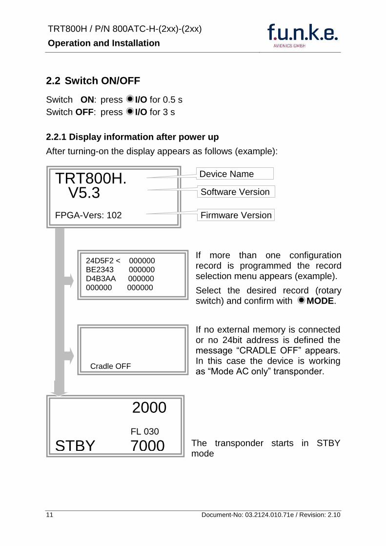
TRT800H PN 800ATC-H-(2xx)-(2xx)
Operation and Installation
12 Document-No 03212401071e Revision 210
23 Display - Indications
Value Meaning Remarks
7000 active Squawk
2000 Standby Squawk Could be changed with active Squawk by pressing
FL 030
FLerr
Flight Level
Invalid altitude measuring
Flight Level (in 100 ft steps)
Beyond -1000 35 000 ft C Mode gets inactive
ACS Operational Mode (STBY A-S ACS AC A)
Modes see section 26
IDT transmits Ident-Marking (SPI) ID (bdquoSquawk Identldquo) has been pressed ndash active for 18 s
Transponder replies
on Mode-S Mode-A or Mode-C interrogations
No indication on ADSB and squitter transmission
| Transponder is locked by a ground station and will be directly addressed
Lock Information (indicated below the diamond)
F
G
in-flight
on-ground
Ground-Switch-Info
(if installedavailable)
ACS
7000
TM
PLLTRX DC | BATDIM
IDT FL 030
STBY 2000 F
Passive Squawk
Active Squawk
Test mode indicatior
GND switch status
Operational Mode Standby
SPI indicator
Error indications
Reply indication
Lock out indication
Flight level
Backlight setup
Low battery ind
Operational Mode Active
TRT800H PN 800ATC-H-(2xx)-(2xx)
Operation and Installation
13 Document-No 03212401071e Revision 210
Value Meaning Remarks
Error indicators
PLL PLL Error Internal Error
TRX Transmit Failure Check antenna and wiring
DC Low internal voltage Internal error
FPG FPGA-Failure Internal error
BAT Battery Power too low maybe batterygenerator fault
24 Display-Brightness
In active mode (not standby) press for 2 s
Display indicates ldquoDIMrdquo Adjust brightness (DIM) with rotary knob
Return to normal operation press or wait 5 s
25 Flight-ID (FID)
The FID is an identifier required for Mode S Operation During future application of flight plans a FID could be assigned on a per flight basis If no FID is assigned (todayrsquos normal case) the registration marking of the aircraft should be used as FID The FID should not contain dashes or blanks The FID must not be confused with the 24-bit Aircraft Address
251 Display Flight-ID
Press MODE (repeatedly) until bdquoSTBYldquo appears
Press and hold ID while a counter is shown beside the active squawk During a few seconds Flight Identification is displayed
FID 02
A B C D E F G H
-
TRT800H PN 800ATC-H-(2xx)-(2xx)
Operation and Installation
14 Document-No 03212401071e Revision 210
252 Configure Flight-ID
Press MODE (repeatedly) until bdquoSTBYldquo appears
Press and hold ID while a counter is shown beside the active squawk Release ID when ldquoCHANGE FIDrdquo is displayed
Enter Flight-Id with cursor button and rotary knob
Press MODE to save and return to STBY
Please refer to section 454 for configuration of the 24-bit Address (AA) and Aircraft Category (AC)
26 Transponder Mode selection
Press MODE (repeatedly) to select from following Modes
STBY bdquoStandbyldquo Transponder does not respond to any interrogation Squitter and ADS-B output is not active
A C S bdquoMode A+C+Sldquo Standard condition transponder responds to mode A C and S interrogations
A ndash S bdquoMode A+S no Cldquo Altitude is not transmitted (neither on C nor on S requests) All other Mode-S data as well as Mode-A replies are transmitted
Enter FID left-aligned without any blanks or dashes () eg 12345621DEFAV for the marking D-EFAV The last remaining digits shall be filled with blanks
CHANGE FID
_ _ _ _ _ _ _ _ A B C D E F G H
- exit
TRT800H PN 800ATC-H-(2xx)-(2xx)
Operation and Installation
15 Document-No 03212401071e Revision 210
If no 24-bit address (AA) was defined or entered as ldquo000000ldquo the transponder operates as a Mode AC transponder in that case the following Modes are possible apart from Standby
A C ndash bdquoMode A+Cldquo Transponder replies only on Mode A and Mode-C interrogations
A ndash ndash bdquoMode Aldquo Transponder replies only on Mode A interrogations
In STBY (Standby) mode all transponder transmissions are disabled completely Therefore the transponder is not visible in this mode to air traffic control or the anti-collision systems onboard other aircrafts
Never use the STBY mode in flight unless you are requested to do so by air traffic control Always remember to put the transponder in active mode prior to take off
27 Squawk-Setting
The active Squawk is displayed in the upper line while the standby Squawk is presented at the lower line
Setting the Standby Squawk
Press to set the cursor (bdquo^ldquo) turn rotary knob to set numbers of the standby Squawk
Press to activate the Standby Squawk (this moves the current active Squawk into Standby)
28 VFR ndash Squawk
The transponder features a user-defined squawk code for VFR-flight (factory setting 7000)
Activate VFR-Squawk
Press VFR (bdquoVFRldquo is indicated) now the active Squawk is moved into Standby but not visible because the indication of the Standby Squawk is overlapped by bdquoVFRldquo
TRT800H PN 800ATC-H-(2xx)-(2xx)
Operation and Installation
16 Document-No 03212401071e Revision 210
Display Standby Squawk
Press VFR or or use the rotary knob (the VFR-Squawk remains active)
Example
VFR VFR
Now the Standby Squawk can be adjusted by using the rotary knob and activated with
In order to store the current active Squawk as new VFR-Squawk (replacing the factory setting 7000) Press and hold VFR until an bdquoSldquo is indicated (approx 3 s) after releasing the button bdquoVFRldquo is shown
29 ID ndash Special Position Identification (SPI) ldquoSquawk Identrdquo
Press ID to activate transmission of the special position identification pulse with every reply within 18 seconds ldquoIDTrdquo appears on the display
By pressing ID a special position identification pulse (SPI) is transmitted with every reply within 18 seconds which causes an accented marking on the Controllerrsquos screen The bdquoSpecial Position Identificationldquo has to be activated after the bdquoSquawk Identldquo request of the Controller
210 Error-Codes
Please refer to 23 Display - Indications for possible displayed errors
7000
FL 030
STBY 4700
7000
FL 030
STBY VFR
4700
FL 030
STBY 5600
TRT800H PN 800ATC-H-(2xx)-(2xx)
Operation and Installation
17 Document-No 03212401071e Revision 210
3 INSTALLATION
31 Notes
The following suggestions should be considered before installing
The assigned installation company will supply wiring For diagrams refer to 37 Wiring
Transponder External Memory all cables and antennas shall be installed according to bdquoFAA AC-14313-2A Acceptable Methods Techniques and Practices ndash Aircraft Alterationsldquo and the appropriate manufacturerrsquos instructions
32 Telecommunication data
Depending on your national telecommunications legislation the following data may be required when applying for the aircraft radio station license
Manufacturer funke AVIONICS GmbH
Type Designation TRT800H
EASA Number EASA21O269
Transmitter Power Output
126 W
Frequency 1090 MHz
Emission Designator 12M0M1D
33 Scope of Delivery
Item namenumber Description
TRT800H Transponder TRT800H
TRT800EMSS External Memory (Aircraft-Address-Adaptor with wiring)
M4X8ZSW (3 pieces) screw for panels up to 5 mm thickness
56S101A4 TNC antenna connector
03212401071e Manual bdquoOperation and Installationldquo
EASA Form 1
TRT800H PN 800ATC-H-(2xx)-(2xx)
Operation and Installation
18 Document-No 03212401071e Revision 210
34 Unpacking and Inspecting of the Equipment
Carefully unpack the equipment and inspect for transport damages If a damage claim has to be filed save the shipping container and all packing materials as evidence to your claim
35 Mounting
In cooperation with a maintenance shop location and kind of the installation are specified The maintenance shop can supply all cables Suitable sets of cables are available from funke AVIONICS GmbH
Select a position away from heat sources Provide space for adequate convection cooling
Leave sufficient space for the installation of cables and connectors
Avoid sharp bends and wiring close to control cables
Leave sufficient lead length for inspection or repair of the wiring of the connector (containing the memory) so that when the mounting hardware for the rear connectors is removed the assembly may be pulled forward several inches
Bend the harness at the rear connectors to inhibit water droplets (formed due to condensation) from collecting in the connector
For mounting detailsdrawing refer to chapter 3122 Mounting Advices
For storage or reshipment the original packaging should be used
TRT800H PN 800ATC-H-(2xx)-(2xx)
Operation and Installation
19 Document-No 03212401071e Revision 210
36 Equipment Connections
361 Electrical Connections
One 15 pin D-SUB miniature connector includes all electrical connections except for the antenna Use only an External Memory Adapter TRT800EMxx as this is part of the certification and includes a memory device in which the ICAO 24-bit Aircraft Address is stored
3611 Mutual Suppression
Other equipment on board (e g DME) may transmit in the same frequency band as the transponder
If such a device is installed a suppression wiring shall be installed in order to protect the receiving parts of the different devices from in-band transmissions
Mutual suppression is a synchronous pulse that is sent to the other equipment to suppress transmission of a competing transmitter for the duration of the pulse train transmission The transponder transmission may be suppressed by an external source and vice versa
To activate mutual suppression connect the SUPP_IO signal to the according signals of the other equipment
3612 Ground Switch
If an external Ground-Switch is connected to the transponder and activated in the setup the transponder can detect if the aircraft is airborne or on the ground This allows the transponder to automatically activate the Ground mode whenever the aircraft is on ground
In order to activate this feature the input bdquoFLY-GNDldquo must be connected to an external switch which connects the input pin with bdquoGNDldquo when the gear is weighted or remains open in the other case
This feature must additionally be activated in the Setup For details on configuration please refer to section 454
The (+UB)-wire has to protected by circuit breaker (2 Amp)
TRT800H PN 800ATC-H-(2xx)-(2xx)
Operation and Installation
20 Document-No 03212401071e Revision 210
3613 Auto-On
The Auto-On input allows to define how the transponder will behave when power is supplied to it
If the aircraft is equipped with a dedicated avionics master switch that switches the power supply to the transponder the pin Auto-On must be wired together with the UB+ pin to the avionic master switch The onoff button on the transponder is without function in that case The transponder will start automatically whenever power is supplied
On aircraft without such an avionics master switch the pin Auto-On must be left unconnected In this case the transponder must be switched on and off via the transponders onoff button on the front panel
362 Static Air Port
Install a silicon soft tube fitting the 5 mm static air hose at the backside of the transponder and secure plumbing with appropriate clamps
37 Wiring
371 Conductor Cross Section
Power Supply (Power GND) AWG20 (062 mmsup2)
Signals AWG22 (038 mmsup2)
The conductors must be approved for aircraft use
TRT800H PN 800ATC-H-(2xx)-(2xx)
Operation and Installation
21 Document-No 03212401071e Revision 210
372 Pin Assignment
The transponder may only be operated together with an external memory address adaptor TRT800EMxx
Pin Signal Remarks Adaptor
Typ(4)
TRT800
EM
Adaptor
Typ(4)
TRT800
EMSS
Adaptor Typ
TRT800
EMRS
1 GND -
2 Remote control(1) Input
3 EEPROM Signal TRT800EMxx internal
4 EEPROM Signal TRT800EMxx internal
5 TX RS-232 Serial Output
6 Switched +UB(1) Output
7 Remote control(1) Output
8 +UB power supply Input
9 GND -
10 EEPROM VCC TRT800EMxx internal
11 EEPROM GND TRT800EMxx internal
12 RX RS-232 Serial Input
13 Suppression Input Output
14 Auto-On(2) Input(2)
15 Fly-GND Switch(3) Input(3)
= in the plug and get out = in the plug and not get out ∕ = internal connection to the device
(1) SWITCHED +UB OUT Interface Remote control
May only be used for compatible funke AVIONICS devices Do not connect pins if interface is not used
(2) Auto-On Connect to +UB override front panel onoff button Leave unconnected to use front panel onoff button
(3) Ground Switch
FLY-GND
If an external Ground Switch is connected it must connect this pin to GND to indicate the on-ground condition Leave open otherwise
(4) Adaptors TRT800EM amp TRT800EMSS
Adaptor version does not provide full interface capability (see table for details)
TRT800H PN 800ATC-H-(2xx)-(2xx)
Operation and Installation
22 Document-No 03212401071e Revision 210
373 Cable plan External Memory EM800
3731 Cable plan TRT800EMRS (older version with interface remote)
to SN 90932013
DSUB 15pol
TRT800HTRT800A
lt PIN-5 gt
lt PIN-12gt
lt PIN-15gt
lt PIN-13gt
lt PIN-7 gt
lt PIN-2 gt
lt PIN-6 gt
lt PIN-1 gt
lt PIN-9 gt
lt PIN-8 gt
lt PIN-14gt
TXD
RXD
FLY_GND
SUPP_IO
GND
open
cable
ends
Remote Binder
Connector
female
white
black
yellow
red
shield
blue
red
brown
GND
+UB
AUTO-ON(2)(3)
black
white
red
yellow
shield
Binder Connector female
(solder side)
1 2 3 4 5 6 7 8
9 10 11 12 13 14 15
D-SUB Connector female
(solder side)
open
cable
ends
1 New interface available
-at TRT800H starting from SN 30430109 with SW V53
-at TRT800A starting with SW V53 2 New TRT800H interface starting from HW 60 3 port function not available at TRT800A
3
4 2
5 1
RMT-LIGHT
GND
RMT-TXD
RMT-SW+UB
RMT-RXD
RMT-TXD(1)
RMT-RXD(1)
RMT-SW+UB(2)(3)
RMT-LIGHT(2)
GND(1)
TRT800H PN 800ATC-H-(2xx)-(2xx)
Operation and Installation
23 Document-No 03212401071e Revision 210
3732 Cable plan TRT800EMRS (newer version with interface remote)
from SN 90932114
DSUB 15pol
TRT800HTRT800A
lt PIN-5 gt
lt PIN-12gt
lt PIN-15gt
lt PIN-13gt
lt PIN-7 gt
lt PIN-2 gt
lt PIN-6 gt
lt PIN-1 gt
lt PIN-9 gt
lt PIN-8 gt
lt PIN-14gt
TXD
RXD
FLY_GND
SUPP_IO
GND
open
cable
ends
Remote Binder
Connector
female
white
brown
yellow
green
shield
blue
red
brown
GND
+UB
AUTO-ON(2)(3)
brown
white
green
yellow
shield
Binder Connector female
(solder side)
1 2 3 4 5 6 7 8
9 10 11 12 13 14 15
D-SUB Connector female
(solder side)
open
cable
ends
1 New interface available
-at TRT800H starting from SN 30430109 with SW V53
-at TRT800A starting with SW V53 2 New TRT800H interface starting from HW 60 3 port function not available at TRT800A
3
4 2
5 1
RMT-LIGHT
GND
RMT-TXD
RMT-SW+UB
RMT-RXD
RMT-TXD(1)
RMT-RXD(1)
RMT-SW+UB(2)(3)
RMT-LIGHT(2)
GND(1)
TRT800H PN 800ATC-H-(2xx)-(2xx)
Operation and Installation
24 Document-No 03212401071e Revision 210
3733 Cable plan TRT800EMSS (newer version without interface remote)
from SN 91032115
The External ndash Memory ndash Address - Adapter TRT800EMxx contains electronic parts and must not be opened Opening or modifying the connector leads to the loss of airworthiness certification
DSUB 15pol
TRT800HTRT800A
lt PIN-5 gt
lt PIN-12gt
lt PIN-15gt
lt PIN-13gt
lt PIN-1 gt
lt PIN-9 gt
lt PIN-8 gt
lt PIN-14gt
TXD
RXD
FLY_GND
SUPP_IO
GND
open
cable
ends
white
brown
yellow
green
shield
blue
red
brown
GND
+UB
AUTO-ON(2)(3)
open
cable
ends
2 New TRT800H interface starting from HW 60 3 port function not available at TRT800A
1 2 3 4 5 6 7 8
9 10 11 12 13 14 15
D-SUB Connector female
(solder side)
TRT800H PN 800ATC-H-(2xx)-(2xx)
Operation and Installation
25 Document-No 03212401071e Revision 210
38 Antenna
381 Antenna Selection
Recommended antennas see section 311 Accessories
Choose an antenna type compatible with the vehicle and the mounting location
Specified features depend on proper installation of the antenna
The radiation pattern needs to be verified considering aircraft type and mounting location
The electrical interference between the antenna and any other equipment must be taken into account in such a way that no reduction of the performance of any other system will occur
Install only certified antennas
382 Installation Recommendation
Take note of the antenna manufacturerrsquos instructions
The usually deployed Dipole- or Blade antennas necessarily require a high frequency capable solid metal ground plane at the antenna base
For installation in composite aircrafts ground planes are to be added The ground plane should be as large as possible but in any case not smaller than 10 cm x 10 cm If in doubt please contact the aircraft manufacturer
Keep away three feet from any other antenna
Pursue mounting in vertical position under the belly in flight direction
383 Antenna Wiring
Suitable antenna cables see section 311 Accessories
Keep wiring as short as possible
The smallest cable bend radius is 10cm Avoid sharp bends
Keep away from an ADF antenna cable at least 12 inches
Electrical connections to the antenna shall be protected against moisture to avoid loss of efficiency
TRT800H PN 800ATC-H-(2xx)-(2xx)
Operation and Installation
26 Document-No 03212401071e Revision 210
39 Post-Installation Check
All steering and control functions of the aircraft are to be examined in order to exclude disturbances by the wiring
The most important factor in the transponder configuration is the setting of the ICAO address (see section 454)
Attenuation from antenna to transponder at 1090 MHz must not exceed 15 dB
A certified maintenance shop must verify proper operation of the transponder by testing in accordance with Appendix F of ldquo14 CFR Part 43 ndash ATC Transponder Tests and Inspectionsrdquo
TRT800H PN 800ATC-H-(2xx)-(2xx)
Operation and Installation
27 Document-No 03212401071e Revision 210
310 Starting Up
Turn the transponder on with IO After start-up the following screens appear
311 Accessories
Part Number Description
TRKABEL1 Antenna cable 10 m (32 ft) TNC BNC
TRKABEL2 Antenna cable 25 m (82 ft) TNC BNC
TRKABEL3 Antenna cable 40 m (132 ft) TNC BNC
TRKABEL4 Antenna cable 65 m (213 ft) TNC BNC
TRT800EMRS External-Memory (Aircraft-Address-Adaptor) Connection cable with interface TRT-Remote control
CI-105 TransponderDME Antenna TSO C66b C74c
CI105 Comant Industries Inc
Height 325rdquo Weight 90 g (02 lbs)
AV22 Transponder Rod antenna TSO C74c
AV-22 R A Miller Industries
The TRT800H starts in standby mode (indicated with STBY) In order to change into operational mode (indicated with ACS) press MODE If ground switch is connected and status ldquoin flightrdquo is selected TRT800H starts in active mode
Very important is the correct configuration of the 24bit Aircraft-Address (see 454 General Setup)
TRT800H V53
FPGA-Vers 102
2000 FL 030
STBY 7000
TRT800H PN 800ATC-H-(2xx)-(2xx)
Operation and Installation
28 Document-No 03212401071e Revision 210
312 Drawings
3121 Dimensions
20mm15 mm
170 mm
TRT800TRT800H
65 mm
65
mm
Oslash 57 mm
Static Air
Antenna
PowerRS232
3122 Mounting Advices
Connections Area
8
0 m
m
Panel Cut-out
470 mm
470
mm
575 mm
4 x Oslash 4 mm
Oslash
Connector (plug) has to be clamped with both spring locks
No screws may be turned in more than max 15mm into the device ndash even if no hard limit is noticeable
Fixing clips (spring) left right
TRT800H PN 800ATC-H-(2xx)-(2xx)
Operation and Installation
29 Document-No 03212401071e Revision 210
4 TRANSPONDER SETTINGS
41 Overview
The TRT800H is capable of storing the following information
ICAO 24-Bit Aircraft-Address (AA)
Aircraft Category (AC)
Flight Identification (FID)
Ground-Switch (YesNo)
Speed Category (RI)
RS232 Interface Configuration
All of these data are configurable in the Setup and are stored in the external memory module integrated within the housing of the D-Sub connector (included in the delivery)
The cable with this connector shall remain in the aircraft even if the unit is removed to ensure that the ICAO 24bit aircraft address is fixed to the aircraft
Additionally the following usertransponder related settings are stored transponder internally
Active Squawk
Passive Squawk
VFR Squawk
Altitude offset
Display brightness
42 Display Configuration Summary
Transponder provides the opportunity to show summary of complete current settings To access configuration summary pages push and hold
ID in Standby mode Release ID if ldquoSHOW SETUPrdquo is displayed The summary is subdivided into the following pages
TRT800H PN 800ATC-H-(2xx)-(2xx)
Operation and Installation
30 Document-No 03212401071e Revision 210
Page 1
Aircraft Address
Aircraft Category
Flight Identification
MODE
Page 2 Speed Category
Ground Switch option
Remote Header option
MODE
Page 3 RS-232 Settings
Protocol baud rate position (if available)1
MODE
Page 4 Altitude correction settings
(part 1)
MODE
Page 5 Altitude correction settings
(part 2)
Note 1 Position data will only be displayed if
a GPS protocol is set as interface protocol (NMEA FREEFLIGHT AR-NAV)
18000 ft 0ft 25000 ft + 100ft 35000 ft - 50ft
exit
ALTITUDE CORRECTION 2000 ft 0ft 10000 ft + 100ft next
RS-232 NMEA Baud 4800 Pos 481 99 next
Speed Cat 8 Ground Sw YES Remote Hd NO next
AA F E 1 2 3 4 AC 1 9 FID 4 4 E 1 2 3 next
TRT800H PN 800ATC-H-(2xx)-(2xx)
Operation and Installation
31 Document-No 03212401071e Revision 210
GPS receiver is connected and transmits data (if not ldquoPos no datardquo is displayed)
a valid position is transmitted (if not ldquoPos wrong datardquo is displayed)
While configuration summary page is displayed no new position data will be processed
43 General settings
431 ICAO 24-Bit Aircraft Address (AA)
Ask your national aviation authority (e g in Germany LBA Referat B5 Department ldquoVerkehrszulassungrdquo) how to obtain the AA In the case of aerial sports equipment the contact point would be the respective associations Only the assigned AA has to be used and must not be modified at any time because a duplicate address would jeopardize the data surveillance and integrity figures of Mode S
If no AA is stored after power on the display shows ldquoCRADLE OFFrdquo and the transponder operates in Mode AC
(Configuration of the AA see section 454)
432 Aircraft Category (AC)
Code Description Code Description
11 Emergency Vehicle 1C Ultra-Light Paraglider
12 Service Vehicle 1E Drone
19 Glider 21 Aircraft (D-Exxx) lt 15500 lbs Motor Glider (D-Kxxx)
1A Balloon amp Airship 22 Aircraft ge 15500 lbslt 75000 lbs
1B Paratrooper 27 Rotorcraft
Only one of the Codes mentioned in the table above must be used
Setuprarr454
Setuprarr454
TRT800H PN 800ATC-H-(2xx)-(2xx)
Operation and Installation
32 Document-No 03212401071e Revision 210
433 Flight-ID (FID)
Per ICAO regulation Mode-S data must contain a valid flight identification (FID) to ensure that the correlation between flight plan and radar data will work automatically
FID setting is required to correspond to the aircraft identification that has been specified at item 7 of the ICAO flight plan It contains seven characters at a maximum (left-aligned no additional zeros dashes or spacesblanks)
For an aircraft using a company call sign the Flight-ID mostly consists of the ICAO three-letter designator for the aircraft operator followed by an identification code eg KLM511 BAW213 JTR25
If no company call sign is used or no flight plan is filed the default FID to be set consists of the registration marking of the aircraft (eg DEABC) with no dashes spacesblanks or additional zeros even if they are included in the registration marking on the aircraft (tail number) While entering the FID into the transponder the last remaining digits must be filled with blanks
The ICAO Flight Plan only specifies 7 characters for FID funke AVIONICS reserves 8 characters as stated in ED-73B for further expansion of the flight plan
The user shall only program 7 characters for FID
Setuprarr454
TRT800H PN 800ATC-H-(2xx)-(2xx)
Operation and Installation
33 Document-No 03212401071e Revision 210
434 Reply Information - Speed Category (RI)
Besides AA AC and FID another important part of the Mode-S data is the Speed Category of the respective aircraft This speed category shall be configured in the setup and must contain one of the following codes
Code Description
08 No maximum airspeed data available
09 Maximum airspeed le 75 kt
10 75 kt gt maximum airspeed le 150 kt
11 150 kt gt maximum airspeed le 300 kt
12 300 kt gt maximum airspeed le 600 kt
13 600 kt gt maximum airspeed le 1200 kt
14 Maximum airspeed gt 1200 kt
15 Not assigned
44 Optional settings
441 Option Ground-Switch
If a ground switch is connected (and enabled in setup) the transponder is able to determine on-ground and in-flight state On-ground state is activated automatically once the gear touches the ground On-ground state is indicated on display by symbol G (apart from lsquoFrsquo for In-flight-state)
In On-ground-state the transponder will reply differently to certain addressed interrogations Also the transmission rate of some periodically sent data (squitters ADS-B) is reduced This allows ATC to distinguish between airborne aircraft and those on the ground and it reduces the Mode S channel load
For small aircraft authorities normally do not require such a ground switch In this case the transponder will use the same data formats on the ground as in the airborne state
Setuprarr454 Wiringrarr373
Setuprarr454
TRT800H PN 800ATC-H-(2xx)-(2xx)
Operation and Installation
34 Document-No 03212401071e Revision 210
442 Option Remote Header
The transponder provides a TRT800RT remote control interface If a remote header TRT800RT is connected transponder can be remote controlled via this interface Remote interface provides control of all standard user inputs available during standard operational mode For more information see TRT800RT manual Remote control interface de-activation is setup configurable Remote control interface must only be connected to TRT800RT
443 Serial Interface (RS232)
Using serial interface a GPS receiver can be connected to broadcast own position via ADS-B Out position message Position could be received by other appropriately equipped aircrafts and processed for collision avoidance ADS-B Out functionality
The ADS-B function of this device has not been evaluated during the FAA TSO certification process other than to ensure non-interference Due to the SW assurance of DAL D the ADS-B function cannot be used in the US National Airspace Connecting a GPS source will not comply to FAA certification requirements with regard to ADS-B
Supported formatsprotocols are
Option Description Baud rate
FREEFLIGHT GPSWAAS Sensor 1201
NexNav NNL 3101
19200
AR-NAV Bendix King
KLN 89B KLN 94 ldquoStandard RS232 Sentencerdquo
KMD 150 ldquoSentence Type 1rdquo
Garmin 400 Series ldquoSentence Type 1rdquo (with and without altitude data)
9600
NMEA NMEA-Format data format RMC is expected
4800
Setuprarr454 Wiringrarr373
Setuprarr454 Wiringrarr373
TRT800H PN 800ATC-H-(2xx)-(2xx)
Operation and Installation
35 Document-No 03212401071e Revision 210
Option Description Baud rate
FAVISIA Glass Cockpit support
FAVISIA Data format to be processed in FAVISIA avionics suite
-
FAVISIA+GPS Data format to be processed in FAVISIA avionics suite (output) and additional processing of incoming NMEA GPS-Receiver position data to support the ADS-B Out functionality
4800
Other
Comm-AB-support
Data format for special purpose An additional data link processor allows COMM-AB operation and processing of the position information of a flight management system simultaneously
38400
Disabled No communication via RS232 interface -
444 Altitude CorrectionOffset
The TRT800H has an integrated temperature compensated high-precision pressure sensor This sensor is factory-calibrated so that it will yield accurate flight level (uncorrected pressure altitude) within the entire altitude range
However due to differences in calibration of the TRT800H pressure sensor and the altimeter in the cockpit it may become necessary to adjust the TRT800H pressure readings so that the value indicated and transmitted by the TRT800H corresponds to the indication of the primary altimeter seen by the pilot within 125 feet (as specified in ETSO C88aSAE AS 8003)
Setting for all described GPS-systems
1 2 position messages per 2 sec
Setuprarr455
TRT800H PN 800ATC-H-(2xx)-(2xx)
Operation and Installation
36 Document-No 03212401071e Revision 210
The check for correspondence between the primary altimeter and the TRT800H is usually performed every 24 months as part of the aircrafts altimeter checks
Altitude correction is based on setup configurable offset values at five interpolation points ( 2000 8000 18000 25000 and 35000 ft)The offset value itself is limited to a range from -100 to + 100ft at each point (10ft steps)
45 Setup Procedure
Programming of the ICAOA 24-bit Aircraft Address and of the Aircraft Category shall be executed by qualified personnel only
A wrong Aircraft Address or Flight ID may cause serious problems ATC or with ACASTCAS systems
Pilot and owner are responsible for correctly set transponder data
451 Setup Menu Control
In order to access the functions described in the following paragraphs push and hold ID in Standby mode Release ID if desired counter value menu name is displayed to enter the menu The following menu entries are selectable
Count Displayed Name Function
03 FID FID is displayed
48 CHANGE FID Enter FID setup page
913 SHOW SETUP Enter setup summary listed on different pages (no changes possible)
2528 ENTER SETUP Enter transponder general configuration pages
3134 ALTITUDE CORRECTION
Enter altitude correction menu
TRT800H PN 800ATC-H-(2xx)-(2xx)
Operation and Installation
37 Document-No 03212401071e Revision 210
452 Transponder configurationrecord structure
Aircraft related parts of transponder configuration are stored in one out of eight possible records (record=presetting) Each record contains the following information
Aircraft Address (AA 24bit)
Aircraft category (AC)
Flight identification (FID 6-8 numbersletters)
RS-232 Interface setting (eg GPS protocol)
Ground-Switch setting (Installed YesNo)
Speed category (RI) of the respective aircraft
Remote Header setting (Installed YesNo)
User related settings (eg squawk codes display brightness) are stored once in one global record (transponder internally)
453 Transponder configurationrecord handling
At least one record is stored in external memory Up to 8 records can be additional be applied during setup process
If more than one record is applied the active record must be selected out of a list (determined by FID) during start-up of the transponder
Previously applied records can be deleted again by filling FID with zerorsquos only
454 General Setup
Any menu item can be passed by MODE If no changes are made the original settings will remain stored Modification of one menu item does not impact the others No entries will be deleted
TRT800H PN 800ATC-H-(2xx)-(2xx)
Operation and Installation
38 Document-No 03212401071e Revision 210
Step Display (Example)
1 Start-up Transponder
2 Ensure the transponder-mode is bdquoSTBYldquo If necessary change the mode by pressing MODE
3 Press ID A counter is shown at the upper-right corner Hold ID till ldquoENTER SETUPrdquo is displayed
4 After release of ID the first setup menu is displayed
5 helliphellipselect position (^)
rotary knobchange value
MODE
6 With the rotary knob you can select bdquoyesldquo if a Ground Switch is installed if not select ldquonordquo and proceed with step 7
MODE
Record 1
GND Switch YesNo
next
AA EF123456
AC 18
FID ^BCDEFG
next
AA EF123456
AC 18
FID ABCDEFG
next
ENTER SETUP 26
2000 FL 030
STBY 7000
TRT800H PN 800ATC-H-(2xx)-(2xx)
Operation and Installation
39 Document-No 03212401071e Revision 210
Step Display (Example)
7 At this stage the respective speed category shall be selected by using the rotary knob
MODE
8 At this stage a GPS receiver for ADS-B Out can be selected (Selectable by rotary knob)
MODE
9 At this stage remote interface for communication between TRT800H and remote header can be activated (Selectable by rotary knob)
Remote interface must only be activated if a remote header is connected
MODE
10 With ID further Records can now be created and configured as described in the aforementioned steps At start-up of the transponder one of the defined records with all associated configurations need to be selected
MODE
Records ID=Edit Records
EXIT
Record 1
REMOTE Header YesNo
next
Record 1
GPSINTEXT NMEA
next
Record 1
Speed Cat 08-15
next
TRT800H PN 800ATC-H-(2xx)-(2xx)
Operation and Installation
40 Document-No 03212401071e Revision 210
Step Display (Example)
11 You have now left the configuration mode and are back in normal operation
12 Switch off the transponder
13 Switch on the transponder Your ICAO 24-Bit Aircraft Address is now stored
TRT800H V53
FPGA-Vers 102
2000 FL 030
STBY 7000
TRT800H PN 800ATC-H-(2xx)-(2xx)
Operation and Installation
41 Document-No 03212401071e Revision 210
455 Altitude Correction Setup
Altitude correction setup shall be executed by qualified personnel only
Pilot and owner are responsible for correctly set altitude offset values
The usesetting of altitude correction values is only necessary in exceptional cases (see 444 for details)
Altitude correction is based on five interpolation points ( 2000 10000 18000 25000 and 35000 ft)The offset value at each interpolation point can be adjusted in a range from -100 to + 100ft at each point (10ft steps) Offset values set to zero at each interpolation point deactivates altitude correction (defaultfactory setting)
Step Display (Example)
1 Start-up Transponder
2 Ensure the transponder-mode is bdquoSTBYldquo If necessary change the mode by pressing MODE
3 Press ID A counter is shown at the upper-right corner Hold ID till ldquoALTITUDE OFFSETrdquo is displayed
ALTITUDE OFFSET 33
2000 FL 030
STBY 7000
Descriptionrarr444
TRT800H PN 800ATC-H-(2xx)-(2xx)
Operation and Installation
42 Document-No 03212401071e Revision 210
Step Display (Example)
4 After release of ID the first altitude level + corresponding offset value is displayed
5 Change offset value with rotary knob
MODE
6 (9) Repeat last step for another 4 altitude levels 10000ft 18000ft 25000ft 35000ft
MODE
10 You have now left the configuration mode and are back in normal operation
Switch off the transponder
11 Switch on the transponder New altitude offset values will now be used for altitude calculation
Altitude 10000 ft
Offset 0 ft
nextexit
Altitude 2000 ft
Offset 0 ft
next
TRT800H V53
FPGA-Vers 102
2000 FL 030
STBY 7000
Altitude 2000 ft
Offset 0 ft
next
TRT800H PN 800ATC-H-(2xx)-(2xx)
Operation and Installation
43 Document-No 03212401071e Revision 210
5 APPENDIX
51 Technical Data
Compliance CS-ETSO-2C112a
EASA21O269
FAA TSO-C112c
Applicable Documents CS-ETSO-2C112a
FAA TSO-C112c
EUROCAE ED-73C Class 1 Level 2es
RTCA DO-181D Class 1 Level 2es
EUROCAE ED-26
RTCA DO-160D
RTCA DO-178B Software-Level D
Temperature Ranges
Operation -20 degC to +55 degC for 30 min +70degC
Storage -55 degC to +85 degC
Altitude Range le 35 000 ft
Speed Range le 250 kt (TAS)
Shock 6 G Operation
20 G crash safety
Environmental Categories RTCA DO-160D EnvCat [C1Z]CAA[SM]XXXXXXZBAAA[TT]M[B3F3]XXA
Power Supply 138 VDC (10 VDC 16 VDC)
040 A 138 VDC (typ)
070 A 138 VDC (max)
10 W (max)
TRT800H PN 800ATC-H-(2xx)-(2xx)
Operation and Installation
44 Document-No 03212401071e Revision 210
Fuse External 2A-slow-blow fuse
Mounting Panel cut-out d=575 mm
Weight 06 kg (132 lbs)
Receiver Characteristics
Sensitivity
RF input power level resulting in a 90 reply rate
A MTL for ATCRBS and ATCRBSMode S All-Call interrogations -74 dBm plusmn3 dB
B MTL for Mode S interrogations -74 dBm plusmn 3 dB
Reply transmission frequency
1090 plusmn 1 MHz
RF Peak Power Output 21 dBW (126 W) at antenna base (with maximum cable attenuation of 15 dB)
Squitter (ADS-B) transmitted at random intervals uniformly distributed over the range from 08 to 12 seconds full self-verification of data and occurrence
Mode S Elementary Surveillance
ICAO 24-bit Aircraft Address (Hex-Code)
aircraft address as assigned by national aviation authority
FID Flight ID Flight Plan call sign or aircraft registration marking
Capability Report Reports the available data and means by which the transponder can report
Pressure Altitude Up to 35 000 ft in 25 ft increments
Flight Status in-flight on-ground
Mode S Enhanced Surveillance
Level 2es Comm-A Comm-B 56112-Bit-Messages
SI-capability
TRT800H PN 800ATC-H-(2xx)-(2xx)
Operation and Installation
45 Document-No 03212401071e Revision 210
52 Environmental Conditions
Characteristic DOndash160D Section Cat Condition
Temperature Altitude 40
C1
Low ground survival temperature
451 ndash 55degC
Low operating temperature 451 ndash 20degC
High ground survival Temperature
452 + 85degC
High Short-time Operating Temperature
452 + 70degC
High Operating Temperature 453 + 55degC
In-Flight Loss of Cooling 454 Z No auxiliary cooling required
Altitude 461 C1 35 000 ft
Temperature Variation 50 C 2degC change rate minimum per minute
Humidity 60 A
Shock 70 A
6 G operational shocks
20 G Crash Safety
Test Type R in all 6 directions
Vibration 80 S Vibration Curve M
Explosion Proofness 90 X No test required
Water Proofness 100 X No test required
Fluids Susceptibilities 110 X No test required
Sand and Dust 120 X No test required
Fungus Resistance 130 X No test required
Salt Spray 140 X No test required
Magnetic Effect 150 Z Less than 03 m
Power Input (DC) 160 B
Voltage Spike Conducted 170 A
Audio Frequency Conducted Susceptibility
180 A
TRT800H PN 800ATC-H-(2xx)-(2xx)
Operation and Installation
46 Document-No 03212401071e Revision 210
Characteristic DOndash160D Section Cat Condition
Induced Signal Susceptibility 190 A
Radio Frequency Susceptibility
200 TT
Emission of RF Energy 210 M
Lightning Induced Transient Susceptibility
220 B3F3
Lightning Direct Effects 230 X No test required
Icing 240 X No test required
Electrostatic Discharge (ESD) 250 A
53 DO-178B Open Problem Reports
There are no open problem reports for the software of this device
TRT800H PN 800ATC-H-(2xx)-(2xx)
Operation and Installation
47 Document-No 03212401071e Revision 210
Notes
f funke funke means ndash fabrication utilities network know-how engineering
funke AVIONICS GmbH Heinz-Strachowitz-Str 4
DE-86807 Buchloe Germany
phone +49-8241 80066 0
fax +49-8241 80066 99 E-mail
servicefunkeavionicsde wwwfunkeavionicsde
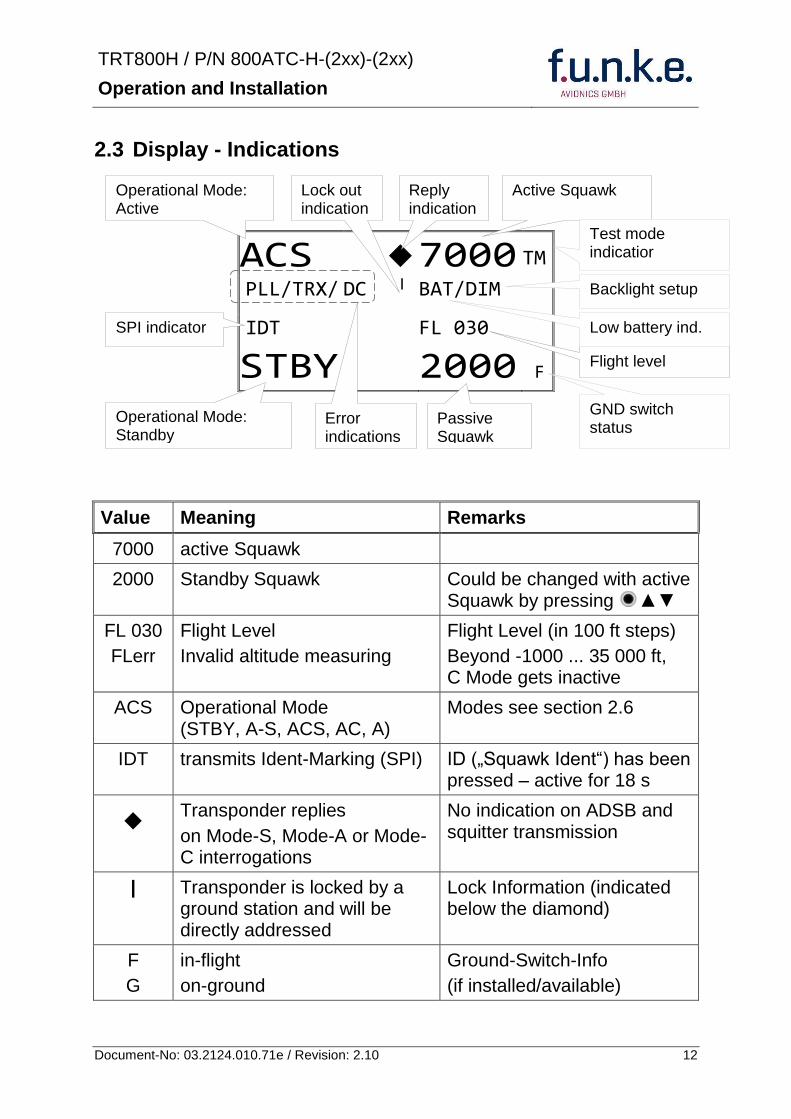
TRT800H PN 800ATC-H-(2xx)-(2xx)
Operation and Installation
13 Document-No 03212401071e Revision 210
Value Meaning Remarks
Error indicators
PLL PLL Error Internal Error
TRX Transmit Failure Check antenna and wiring
DC Low internal voltage Internal error
FPG FPGA-Failure Internal error
BAT Battery Power too low maybe batterygenerator fault
24 Display-Brightness
In active mode (not standby) press for 2 s
Display indicates ldquoDIMrdquo Adjust brightness (DIM) with rotary knob
Return to normal operation press or wait 5 s
25 Flight-ID (FID)
The FID is an identifier required for Mode S Operation During future application of flight plans a FID could be assigned on a per flight basis If no FID is assigned (todayrsquos normal case) the registration marking of the aircraft should be used as FID The FID should not contain dashes or blanks The FID must not be confused with the 24-bit Aircraft Address
251 Display Flight-ID
Press MODE (repeatedly) until bdquoSTBYldquo appears
Press and hold ID while a counter is shown beside the active squawk During a few seconds Flight Identification is displayed
FID 02
A B C D E F G H
-
TRT800H PN 800ATC-H-(2xx)-(2xx)
Operation and Installation
14 Document-No 03212401071e Revision 210
252 Configure Flight-ID
Press MODE (repeatedly) until bdquoSTBYldquo appears
Press and hold ID while a counter is shown beside the active squawk Release ID when ldquoCHANGE FIDrdquo is displayed
Enter Flight-Id with cursor button and rotary knob
Press MODE to save and return to STBY
Please refer to section 454 for configuration of the 24-bit Address (AA) and Aircraft Category (AC)
26 Transponder Mode selection
Press MODE (repeatedly) to select from following Modes
STBY bdquoStandbyldquo Transponder does not respond to any interrogation Squitter and ADS-B output is not active
A C S bdquoMode A+C+Sldquo Standard condition transponder responds to mode A C and S interrogations
A ndash S bdquoMode A+S no Cldquo Altitude is not transmitted (neither on C nor on S requests) All other Mode-S data as well as Mode-A replies are transmitted
Enter FID left-aligned without any blanks or dashes () eg 12345621DEFAV for the marking D-EFAV The last remaining digits shall be filled with blanks
CHANGE FID
_ _ _ _ _ _ _ _ A B C D E F G H
- exit
TRT800H PN 800ATC-H-(2xx)-(2xx)
Operation and Installation
15 Document-No 03212401071e Revision 210
If no 24-bit address (AA) was defined or entered as ldquo000000ldquo the transponder operates as a Mode AC transponder in that case the following Modes are possible apart from Standby
A C ndash bdquoMode A+Cldquo Transponder replies only on Mode A and Mode-C interrogations
A ndash ndash bdquoMode Aldquo Transponder replies only on Mode A interrogations
In STBY (Standby) mode all transponder transmissions are disabled completely Therefore the transponder is not visible in this mode to air traffic control or the anti-collision systems onboard other aircrafts
Never use the STBY mode in flight unless you are requested to do so by air traffic control Always remember to put the transponder in active mode prior to take off
27 Squawk-Setting
The active Squawk is displayed in the upper line while the standby Squawk is presented at the lower line
Setting the Standby Squawk
Press to set the cursor (bdquo^ldquo) turn rotary knob to set numbers of the standby Squawk
Press to activate the Standby Squawk (this moves the current active Squawk into Standby)
28 VFR ndash Squawk
The transponder features a user-defined squawk code for VFR-flight (factory setting 7000)
Activate VFR-Squawk
Press VFR (bdquoVFRldquo is indicated) now the active Squawk is moved into Standby but not visible because the indication of the Standby Squawk is overlapped by bdquoVFRldquo
TRT800H PN 800ATC-H-(2xx)-(2xx)
Operation and Installation
16 Document-No 03212401071e Revision 210
Display Standby Squawk
Press VFR or or use the rotary knob (the VFR-Squawk remains active)
Example
VFR VFR
Now the Standby Squawk can be adjusted by using the rotary knob and activated with
In order to store the current active Squawk as new VFR-Squawk (replacing the factory setting 7000) Press and hold VFR until an bdquoSldquo is indicated (approx 3 s) after releasing the button bdquoVFRldquo is shown
29 ID ndash Special Position Identification (SPI) ldquoSquawk Identrdquo
Press ID to activate transmission of the special position identification pulse with every reply within 18 seconds ldquoIDTrdquo appears on the display
By pressing ID a special position identification pulse (SPI) is transmitted with every reply within 18 seconds which causes an accented marking on the Controllerrsquos screen The bdquoSpecial Position Identificationldquo has to be activated after the bdquoSquawk Identldquo request of the Controller
210 Error-Codes
Please refer to 23 Display - Indications for possible displayed errors
7000
FL 030
STBY 4700
7000
FL 030
STBY VFR
4700
FL 030
STBY 5600
TRT800H PN 800ATC-H-(2xx)-(2xx)
Operation and Installation
17 Document-No 03212401071e Revision 210
3 INSTALLATION
31 Notes
The following suggestions should be considered before installing
The assigned installation company will supply wiring For diagrams refer to 37 Wiring
Transponder External Memory all cables and antennas shall be installed according to bdquoFAA AC-14313-2A Acceptable Methods Techniques and Practices ndash Aircraft Alterationsldquo and the appropriate manufacturerrsquos instructions
32 Telecommunication data
Depending on your national telecommunications legislation the following data may be required when applying for the aircraft radio station license
Manufacturer funke AVIONICS GmbH
Type Designation TRT800H
EASA Number EASA21O269
Transmitter Power Output
126 W
Frequency 1090 MHz
Emission Designator 12M0M1D
33 Scope of Delivery
Item namenumber Description
TRT800H Transponder TRT800H
TRT800EMSS External Memory (Aircraft-Address-Adaptor with wiring)
M4X8ZSW (3 pieces) screw for panels up to 5 mm thickness
56S101A4 TNC antenna connector
03212401071e Manual bdquoOperation and Installationldquo
EASA Form 1
TRT800H PN 800ATC-H-(2xx)-(2xx)
Operation and Installation
18 Document-No 03212401071e Revision 210
34 Unpacking and Inspecting of the Equipment
Carefully unpack the equipment and inspect for transport damages If a damage claim has to be filed save the shipping container and all packing materials as evidence to your claim
35 Mounting
In cooperation with a maintenance shop location and kind of the installation are specified The maintenance shop can supply all cables Suitable sets of cables are available from funke AVIONICS GmbH
Select a position away from heat sources Provide space for adequate convection cooling
Leave sufficient space for the installation of cables and connectors
Avoid sharp bends and wiring close to control cables
Leave sufficient lead length for inspection or repair of the wiring of the connector (containing the memory) so that when the mounting hardware for the rear connectors is removed the assembly may be pulled forward several inches
Bend the harness at the rear connectors to inhibit water droplets (formed due to condensation) from collecting in the connector
For mounting detailsdrawing refer to chapter 3122 Mounting Advices
For storage or reshipment the original packaging should be used
TRT800H PN 800ATC-H-(2xx)-(2xx)
Operation and Installation
19 Document-No 03212401071e Revision 210
36 Equipment Connections
361 Electrical Connections
One 15 pin D-SUB miniature connector includes all electrical connections except for the antenna Use only an External Memory Adapter TRT800EMxx as this is part of the certification and includes a memory device in which the ICAO 24-bit Aircraft Address is stored
3611 Mutual Suppression
Other equipment on board (e g DME) may transmit in the same frequency band as the transponder
If such a device is installed a suppression wiring shall be installed in order to protect the receiving parts of the different devices from in-band transmissions
Mutual suppression is a synchronous pulse that is sent to the other equipment to suppress transmission of a competing transmitter for the duration of the pulse train transmission The transponder transmission may be suppressed by an external source and vice versa
To activate mutual suppression connect the SUPP_IO signal to the according signals of the other equipment
3612 Ground Switch
If an external Ground-Switch is connected to the transponder and activated in the setup the transponder can detect if the aircraft is airborne or on the ground This allows the transponder to automatically activate the Ground mode whenever the aircraft is on ground
In order to activate this feature the input bdquoFLY-GNDldquo must be connected to an external switch which connects the input pin with bdquoGNDldquo when the gear is weighted or remains open in the other case
This feature must additionally be activated in the Setup For details on configuration please refer to section 454
The (+UB)-wire has to protected by circuit breaker (2 Amp)
TRT800H PN 800ATC-H-(2xx)-(2xx)
Operation and Installation
20 Document-No 03212401071e Revision 210
3613 Auto-On
The Auto-On input allows to define how the transponder will behave when power is supplied to it
If the aircraft is equipped with a dedicated avionics master switch that switches the power supply to the transponder the pin Auto-On must be wired together with the UB+ pin to the avionic master switch The onoff button on the transponder is without function in that case The transponder will start automatically whenever power is supplied
On aircraft without such an avionics master switch the pin Auto-On must be left unconnected In this case the transponder must be switched on and off via the transponders onoff button on the front panel
362 Static Air Port
Install a silicon soft tube fitting the 5 mm static air hose at the backside of the transponder and secure plumbing with appropriate clamps
37 Wiring
371 Conductor Cross Section
Power Supply (Power GND) AWG20 (062 mmsup2)
Signals AWG22 (038 mmsup2)
The conductors must be approved for aircraft use
TRT800H PN 800ATC-H-(2xx)-(2xx)
Operation and Installation
21 Document-No 03212401071e Revision 210
372 Pin Assignment
The transponder may only be operated together with an external memory address adaptor TRT800EMxx
Pin Signal Remarks Adaptor
Typ(4)
TRT800
EM
Adaptor
Typ(4)
TRT800
EMSS
Adaptor Typ
TRT800
EMRS
1 GND -
2 Remote control(1) Input
3 EEPROM Signal TRT800EMxx internal
4 EEPROM Signal TRT800EMxx internal
5 TX RS-232 Serial Output
6 Switched +UB(1) Output
7 Remote control(1) Output
8 +UB power supply Input
9 GND -
10 EEPROM VCC TRT800EMxx internal
11 EEPROM GND TRT800EMxx internal
12 RX RS-232 Serial Input
13 Suppression Input Output
14 Auto-On(2) Input(2)
15 Fly-GND Switch(3) Input(3)
= in the plug and get out = in the plug and not get out ∕ = internal connection to the device
(1) SWITCHED +UB OUT Interface Remote control
May only be used for compatible funke AVIONICS devices Do not connect pins if interface is not used
(2) Auto-On Connect to +UB override front panel onoff button Leave unconnected to use front panel onoff button
(3) Ground Switch
FLY-GND
If an external Ground Switch is connected it must connect this pin to GND to indicate the on-ground condition Leave open otherwise
(4) Adaptors TRT800EM amp TRT800EMSS
Adaptor version does not provide full interface capability (see table for details)
TRT800H PN 800ATC-H-(2xx)-(2xx)
Operation and Installation
22 Document-No 03212401071e Revision 210
373 Cable plan External Memory EM800
3731 Cable plan TRT800EMRS (older version with interface remote)
to SN 90932013
DSUB 15pol
TRT800HTRT800A
lt PIN-5 gt
lt PIN-12gt
lt PIN-15gt
lt PIN-13gt
lt PIN-7 gt
lt PIN-2 gt
lt PIN-6 gt
lt PIN-1 gt
lt PIN-9 gt
lt PIN-8 gt
lt PIN-14gt
TXD
RXD
FLY_GND
SUPP_IO
GND
open
cable
ends
Remote Binder
Connector
female
white
black
yellow
red
shield
blue
red
brown
GND
+UB
AUTO-ON(2)(3)
black
white
red
yellow
shield
Binder Connector female
(solder side)
1 2 3 4 5 6 7 8
9 10 11 12 13 14 15
D-SUB Connector female
(solder side)
open
cable
ends
1 New interface available
-at TRT800H starting from SN 30430109 with SW V53
-at TRT800A starting with SW V53 2 New TRT800H interface starting from HW 60 3 port function not available at TRT800A
3
4 2
5 1
RMT-LIGHT
GND
RMT-TXD
RMT-SW+UB
RMT-RXD
RMT-TXD(1)
RMT-RXD(1)
RMT-SW+UB(2)(3)
RMT-LIGHT(2)
GND(1)
TRT800H PN 800ATC-H-(2xx)-(2xx)
Operation and Installation
23 Document-No 03212401071e Revision 210
3732 Cable plan TRT800EMRS (newer version with interface remote)
from SN 90932114
DSUB 15pol
TRT800HTRT800A
lt PIN-5 gt
lt PIN-12gt
lt PIN-15gt
lt PIN-13gt
lt PIN-7 gt
lt PIN-2 gt
lt PIN-6 gt
lt PIN-1 gt
lt PIN-9 gt
lt PIN-8 gt
lt PIN-14gt
TXD
RXD
FLY_GND
SUPP_IO
GND
open
cable
ends
Remote Binder
Connector
female
white
brown
yellow
green
shield
blue
red
brown
GND
+UB
AUTO-ON(2)(3)
brown
white
green
yellow
shield
Binder Connector female
(solder side)
1 2 3 4 5 6 7 8
9 10 11 12 13 14 15
D-SUB Connector female
(solder side)
open
cable
ends
1 New interface available
-at TRT800H starting from SN 30430109 with SW V53
-at TRT800A starting with SW V53 2 New TRT800H interface starting from HW 60 3 port function not available at TRT800A
3
4 2
5 1
RMT-LIGHT
GND
RMT-TXD
RMT-SW+UB
RMT-RXD
RMT-TXD(1)
RMT-RXD(1)
RMT-SW+UB(2)(3)
RMT-LIGHT(2)
GND(1)
TRT800H PN 800ATC-H-(2xx)-(2xx)
Operation and Installation
24 Document-No 03212401071e Revision 210
3733 Cable plan TRT800EMSS (newer version without interface remote)
from SN 91032115
The External ndash Memory ndash Address - Adapter TRT800EMxx contains electronic parts and must not be opened Opening or modifying the connector leads to the loss of airworthiness certification
DSUB 15pol
TRT800HTRT800A
lt PIN-5 gt
lt PIN-12gt
lt PIN-15gt
lt PIN-13gt
lt PIN-1 gt
lt PIN-9 gt
lt PIN-8 gt
lt PIN-14gt
TXD
RXD
FLY_GND
SUPP_IO
GND
open
cable
ends
white
brown
yellow
green
shield
blue
red
brown
GND
+UB
AUTO-ON(2)(3)
open
cable
ends
2 New TRT800H interface starting from HW 60 3 port function not available at TRT800A
1 2 3 4 5 6 7 8
9 10 11 12 13 14 15
D-SUB Connector female
(solder side)
TRT800H PN 800ATC-H-(2xx)-(2xx)
Operation and Installation
25 Document-No 03212401071e Revision 210
38 Antenna
381 Antenna Selection
Recommended antennas see section 311 Accessories
Choose an antenna type compatible with the vehicle and the mounting location
Specified features depend on proper installation of the antenna
The radiation pattern needs to be verified considering aircraft type and mounting location
The electrical interference between the antenna and any other equipment must be taken into account in such a way that no reduction of the performance of any other system will occur
Install only certified antennas
382 Installation Recommendation
Take note of the antenna manufacturerrsquos instructions
The usually deployed Dipole- or Blade antennas necessarily require a high frequency capable solid metal ground plane at the antenna base
For installation in composite aircrafts ground planes are to be added The ground plane should be as large as possible but in any case not smaller than 10 cm x 10 cm If in doubt please contact the aircraft manufacturer
Keep away three feet from any other antenna
Pursue mounting in vertical position under the belly in flight direction
383 Antenna Wiring
Suitable antenna cables see section 311 Accessories
Keep wiring as short as possible
The smallest cable bend radius is 10cm Avoid sharp bends
Keep away from an ADF antenna cable at least 12 inches
Electrical connections to the antenna shall be protected against moisture to avoid loss of efficiency
TRT800H PN 800ATC-H-(2xx)-(2xx)
Operation and Installation
26 Document-No 03212401071e Revision 210
39 Post-Installation Check
All steering and control functions of the aircraft are to be examined in order to exclude disturbances by the wiring
The most important factor in the transponder configuration is the setting of the ICAO address (see section 454)
Attenuation from antenna to transponder at 1090 MHz must not exceed 15 dB
A certified maintenance shop must verify proper operation of the transponder by testing in accordance with Appendix F of ldquo14 CFR Part 43 ndash ATC Transponder Tests and Inspectionsrdquo
TRT800H PN 800ATC-H-(2xx)-(2xx)
Operation and Installation
27 Document-No 03212401071e Revision 210
310 Starting Up
Turn the transponder on with IO After start-up the following screens appear
311 Accessories
Part Number Description
TRKABEL1 Antenna cable 10 m (32 ft) TNC BNC
TRKABEL2 Antenna cable 25 m (82 ft) TNC BNC
TRKABEL3 Antenna cable 40 m (132 ft) TNC BNC
TRKABEL4 Antenna cable 65 m (213 ft) TNC BNC
TRT800EMRS External-Memory (Aircraft-Address-Adaptor) Connection cable with interface TRT-Remote control
CI-105 TransponderDME Antenna TSO C66b C74c
CI105 Comant Industries Inc
Height 325rdquo Weight 90 g (02 lbs)
AV22 Transponder Rod antenna TSO C74c
AV-22 R A Miller Industries
The TRT800H starts in standby mode (indicated with STBY) In order to change into operational mode (indicated with ACS) press MODE If ground switch is connected and status ldquoin flightrdquo is selected TRT800H starts in active mode
Very important is the correct configuration of the 24bit Aircraft-Address (see 454 General Setup)
TRT800H V53
FPGA-Vers 102
2000 FL 030
STBY 7000
TRT800H PN 800ATC-H-(2xx)-(2xx)
Operation and Installation
28 Document-No 03212401071e Revision 210
312 Drawings
3121 Dimensions
20mm15 mm
170 mm
TRT800TRT800H
65 mm
65
mm
Oslash 57 mm
Static Air
Antenna
PowerRS232
3122 Mounting Advices
Connections Area
8
0 m
m
Panel Cut-out
470 mm
470
mm
575 mm
4 x Oslash 4 mm
Oslash
Connector (plug) has to be clamped with both spring locks
No screws may be turned in more than max 15mm into the device ndash even if no hard limit is noticeable
Fixing clips (spring) left right
TRT800H PN 800ATC-H-(2xx)-(2xx)
Operation and Installation
29 Document-No 03212401071e Revision 210
4 TRANSPONDER SETTINGS
41 Overview
The TRT800H is capable of storing the following information
ICAO 24-Bit Aircraft-Address (AA)
Aircraft Category (AC)
Flight Identification (FID)
Ground-Switch (YesNo)
Speed Category (RI)
RS232 Interface Configuration
All of these data are configurable in the Setup and are stored in the external memory module integrated within the housing of the D-Sub connector (included in the delivery)
The cable with this connector shall remain in the aircraft even if the unit is removed to ensure that the ICAO 24bit aircraft address is fixed to the aircraft
Additionally the following usertransponder related settings are stored transponder internally
Active Squawk
Passive Squawk
VFR Squawk
Altitude offset
Display brightness
42 Display Configuration Summary
Transponder provides the opportunity to show summary of complete current settings To access configuration summary pages push and hold
ID in Standby mode Release ID if ldquoSHOW SETUPrdquo is displayed The summary is subdivided into the following pages
TRT800H PN 800ATC-H-(2xx)-(2xx)
Operation and Installation
30 Document-No 03212401071e Revision 210
Page 1
Aircraft Address
Aircraft Category
Flight Identification
MODE
Page 2 Speed Category
Ground Switch option
Remote Header option
MODE
Page 3 RS-232 Settings
Protocol baud rate position (if available)1
MODE
Page 4 Altitude correction settings
(part 1)
MODE
Page 5 Altitude correction settings
(part 2)
Note 1 Position data will only be displayed if
a GPS protocol is set as interface protocol (NMEA FREEFLIGHT AR-NAV)
18000 ft 0ft 25000 ft + 100ft 35000 ft - 50ft
exit
ALTITUDE CORRECTION 2000 ft 0ft 10000 ft + 100ft next
RS-232 NMEA Baud 4800 Pos 481 99 next
Speed Cat 8 Ground Sw YES Remote Hd NO next
AA F E 1 2 3 4 AC 1 9 FID 4 4 E 1 2 3 next
TRT800H PN 800ATC-H-(2xx)-(2xx)
Operation and Installation
31 Document-No 03212401071e Revision 210
GPS receiver is connected and transmits data (if not ldquoPos no datardquo is displayed)
a valid position is transmitted (if not ldquoPos wrong datardquo is displayed)
While configuration summary page is displayed no new position data will be processed
43 General settings
431 ICAO 24-Bit Aircraft Address (AA)
Ask your national aviation authority (e g in Germany LBA Referat B5 Department ldquoVerkehrszulassungrdquo) how to obtain the AA In the case of aerial sports equipment the contact point would be the respective associations Only the assigned AA has to be used and must not be modified at any time because a duplicate address would jeopardize the data surveillance and integrity figures of Mode S
If no AA is stored after power on the display shows ldquoCRADLE OFFrdquo and the transponder operates in Mode AC
(Configuration of the AA see section 454)
432 Aircraft Category (AC)
Code Description Code Description
11 Emergency Vehicle 1C Ultra-Light Paraglider
12 Service Vehicle 1E Drone
19 Glider 21 Aircraft (D-Exxx) lt 15500 lbs Motor Glider (D-Kxxx)
1A Balloon amp Airship 22 Aircraft ge 15500 lbslt 75000 lbs
1B Paratrooper 27 Rotorcraft
Only one of the Codes mentioned in the table above must be used
Setuprarr454
Setuprarr454
TRT800H PN 800ATC-H-(2xx)-(2xx)
Operation and Installation
32 Document-No 03212401071e Revision 210
433 Flight-ID (FID)
Per ICAO regulation Mode-S data must contain a valid flight identification (FID) to ensure that the correlation between flight plan and radar data will work automatically
FID setting is required to correspond to the aircraft identification that has been specified at item 7 of the ICAO flight plan It contains seven characters at a maximum (left-aligned no additional zeros dashes or spacesblanks)
For an aircraft using a company call sign the Flight-ID mostly consists of the ICAO three-letter designator for the aircraft operator followed by an identification code eg KLM511 BAW213 JTR25
If no company call sign is used or no flight plan is filed the default FID to be set consists of the registration marking of the aircraft (eg DEABC) with no dashes spacesblanks or additional zeros even if they are included in the registration marking on the aircraft (tail number) While entering the FID into the transponder the last remaining digits must be filled with blanks
The ICAO Flight Plan only specifies 7 characters for FID funke AVIONICS reserves 8 characters as stated in ED-73B for further expansion of the flight plan
The user shall only program 7 characters for FID
Setuprarr454
TRT800H PN 800ATC-H-(2xx)-(2xx)
Operation and Installation
33 Document-No 03212401071e Revision 210
434 Reply Information - Speed Category (RI)
Besides AA AC and FID another important part of the Mode-S data is the Speed Category of the respective aircraft This speed category shall be configured in the setup and must contain one of the following codes
Code Description
08 No maximum airspeed data available
09 Maximum airspeed le 75 kt
10 75 kt gt maximum airspeed le 150 kt
11 150 kt gt maximum airspeed le 300 kt
12 300 kt gt maximum airspeed le 600 kt
13 600 kt gt maximum airspeed le 1200 kt
14 Maximum airspeed gt 1200 kt
15 Not assigned
44 Optional settings
441 Option Ground-Switch
If a ground switch is connected (and enabled in setup) the transponder is able to determine on-ground and in-flight state On-ground state is activated automatically once the gear touches the ground On-ground state is indicated on display by symbol G (apart from lsquoFrsquo for In-flight-state)
In On-ground-state the transponder will reply differently to certain addressed interrogations Also the transmission rate of some periodically sent data (squitters ADS-B) is reduced This allows ATC to distinguish between airborne aircraft and those on the ground and it reduces the Mode S channel load
For small aircraft authorities normally do not require such a ground switch In this case the transponder will use the same data formats on the ground as in the airborne state
Setuprarr454 Wiringrarr373
Setuprarr454
TRT800H PN 800ATC-H-(2xx)-(2xx)
Operation and Installation
34 Document-No 03212401071e Revision 210
442 Option Remote Header
The transponder provides a TRT800RT remote control interface If a remote header TRT800RT is connected transponder can be remote controlled via this interface Remote interface provides control of all standard user inputs available during standard operational mode For more information see TRT800RT manual Remote control interface de-activation is setup configurable Remote control interface must only be connected to TRT800RT
443 Serial Interface (RS232)
Using serial interface a GPS receiver can be connected to broadcast own position via ADS-B Out position message Position could be received by other appropriately equipped aircrafts and processed for collision avoidance ADS-B Out functionality
The ADS-B function of this device has not been evaluated during the FAA TSO certification process other than to ensure non-interference Due to the SW assurance of DAL D the ADS-B function cannot be used in the US National Airspace Connecting a GPS source will not comply to FAA certification requirements with regard to ADS-B
Supported formatsprotocols are
Option Description Baud rate
FREEFLIGHT GPSWAAS Sensor 1201
NexNav NNL 3101
19200
AR-NAV Bendix King
KLN 89B KLN 94 ldquoStandard RS232 Sentencerdquo
KMD 150 ldquoSentence Type 1rdquo
Garmin 400 Series ldquoSentence Type 1rdquo (with and without altitude data)
9600
NMEA NMEA-Format data format RMC is expected
4800
Setuprarr454 Wiringrarr373
Setuprarr454 Wiringrarr373
TRT800H PN 800ATC-H-(2xx)-(2xx)
Operation and Installation
35 Document-No 03212401071e Revision 210
Option Description Baud rate
FAVISIA Glass Cockpit support
FAVISIA Data format to be processed in FAVISIA avionics suite
-
FAVISIA+GPS Data format to be processed in FAVISIA avionics suite (output) and additional processing of incoming NMEA GPS-Receiver position data to support the ADS-B Out functionality
4800
Other
Comm-AB-support
Data format for special purpose An additional data link processor allows COMM-AB operation and processing of the position information of a flight management system simultaneously
38400
Disabled No communication via RS232 interface -
444 Altitude CorrectionOffset
The TRT800H has an integrated temperature compensated high-precision pressure sensor This sensor is factory-calibrated so that it will yield accurate flight level (uncorrected pressure altitude) within the entire altitude range
However due to differences in calibration of the TRT800H pressure sensor and the altimeter in the cockpit it may become necessary to adjust the TRT800H pressure readings so that the value indicated and transmitted by the TRT800H corresponds to the indication of the primary altimeter seen by the pilot within 125 feet (as specified in ETSO C88aSAE AS 8003)
Setting for all described GPS-systems
1 2 position messages per 2 sec
Setuprarr455
TRT800H PN 800ATC-H-(2xx)-(2xx)
Operation and Installation
36 Document-No 03212401071e Revision 210
The check for correspondence between the primary altimeter and the TRT800H is usually performed every 24 months as part of the aircrafts altimeter checks
Altitude correction is based on setup configurable offset values at five interpolation points ( 2000 8000 18000 25000 and 35000 ft)The offset value itself is limited to a range from -100 to + 100ft at each point (10ft steps)
45 Setup Procedure
Programming of the ICAOA 24-bit Aircraft Address and of the Aircraft Category shall be executed by qualified personnel only
A wrong Aircraft Address or Flight ID may cause serious problems ATC or with ACASTCAS systems
Pilot and owner are responsible for correctly set transponder data
451 Setup Menu Control
In order to access the functions described in the following paragraphs push and hold ID in Standby mode Release ID if desired counter value menu name is displayed to enter the menu The following menu entries are selectable
Count Displayed Name Function
03 FID FID is displayed
48 CHANGE FID Enter FID setup page
913 SHOW SETUP Enter setup summary listed on different pages (no changes possible)
2528 ENTER SETUP Enter transponder general configuration pages
3134 ALTITUDE CORRECTION
Enter altitude correction menu
TRT800H PN 800ATC-H-(2xx)-(2xx)
Operation and Installation
37 Document-No 03212401071e Revision 210
452 Transponder configurationrecord structure
Aircraft related parts of transponder configuration are stored in one out of eight possible records (record=presetting) Each record contains the following information
Aircraft Address (AA 24bit)
Aircraft category (AC)
Flight identification (FID 6-8 numbersletters)
RS-232 Interface setting (eg GPS protocol)
Ground-Switch setting (Installed YesNo)
Speed category (RI) of the respective aircraft
Remote Header setting (Installed YesNo)
User related settings (eg squawk codes display brightness) are stored once in one global record (transponder internally)
453 Transponder configurationrecord handling
At least one record is stored in external memory Up to 8 records can be additional be applied during setup process
If more than one record is applied the active record must be selected out of a list (determined by FID) during start-up of the transponder
Previously applied records can be deleted again by filling FID with zerorsquos only
454 General Setup
Any menu item can be passed by MODE If no changes are made the original settings will remain stored Modification of one menu item does not impact the others No entries will be deleted
TRT800H PN 800ATC-H-(2xx)-(2xx)
Operation and Installation
38 Document-No 03212401071e Revision 210
Step Display (Example)
1 Start-up Transponder
2 Ensure the transponder-mode is bdquoSTBYldquo If necessary change the mode by pressing MODE
3 Press ID A counter is shown at the upper-right corner Hold ID till ldquoENTER SETUPrdquo is displayed
4 After release of ID the first setup menu is displayed
5 helliphellipselect position (^)
rotary knobchange value
MODE
6 With the rotary knob you can select bdquoyesldquo if a Ground Switch is installed if not select ldquonordquo and proceed with step 7
MODE
Record 1
GND Switch YesNo
next
AA EF123456
AC 18
FID ^BCDEFG
next
AA EF123456
AC 18
FID ABCDEFG
next
ENTER SETUP 26
2000 FL 030
STBY 7000
TRT800H PN 800ATC-H-(2xx)-(2xx)
Operation and Installation
39 Document-No 03212401071e Revision 210
Step Display (Example)
7 At this stage the respective speed category shall be selected by using the rotary knob
MODE
8 At this stage a GPS receiver for ADS-B Out can be selected (Selectable by rotary knob)
MODE
9 At this stage remote interface for communication between TRT800H and remote header can be activated (Selectable by rotary knob)
Remote interface must only be activated if a remote header is connected
MODE
10 With ID further Records can now be created and configured as described in the aforementioned steps At start-up of the transponder one of the defined records with all associated configurations need to be selected
MODE
Records ID=Edit Records
EXIT
Record 1
REMOTE Header YesNo
next
Record 1
GPSINTEXT NMEA
next
Record 1
Speed Cat 08-15
next
TRT800H PN 800ATC-H-(2xx)-(2xx)
Operation and Installation
40 Document-No 03212401071e Revision 210
Step Display (Example)
11 You have now left the configuration mode and are back in normal operation
12 Switch off the transponder
13 Switch on the transponder Your ICAO 24-Bit Aircraft Address is now stored
TRT800H V53
FPGA-Vers 102
2000 FL 030
STBY 7000
TRT800H PN 800ATC-H-(2xx)-(2xx)
Operation and Installation
41 Document-No 03212401071e Revision 210
455 Altitude Correction Setup
Altitude correction setup shall be executed by qualified personnel only
Pilot and owner are responsible for correctly set altitude offset values
The usesetting of altitude correction values is only necessary in exceptional cases (see 444 for details)
Altitude correction is based on five interpolation points ( 2000 10000 18000 25000 and 35000 ft)The offset value at each interpolation point can be adjusted in a range from -100 to + 100ft at each point (10ft steps) Offset values set to zero at each interpolation point deactivates altitude correction (defaultfactory setting)
Step Display (Example)
1 Start-up Transponder
2 Ensure the transponder-mode is bdquoSTBYldquo If necessary change the mode by pressing MODE
3 Press ID A counter is shown at the upper-right corner Hold ID till ldquoALTITUDE OFFSETrdquo is displayed
ALTITUDE OFFSET 33
2000 FL 030
STBY 7000
Descriptionrarr444
TRT800H PN 800ATC-H-(2xx)-(2xx)
Operation and Installation
42 Document-No 03212401071e Revision 210
Step Display (Example)
4 After release of ID the first altitude level + corresponding offset value is displayed
5 Change offset value with rotary knob
MODE
6 (9) Repeat last step for another 4 altitude levels 10000ft 18000ft 25000ft 35000ft
MODE
10 You have now left the configuration mode and are back in normal operation
Switch off the transponder
11 Switch on the transponder New altitude offset values will now be used for altitude calculation
Altitude 10000 ft
Offset 0 ft
nextexit
Altitude 2000 ft
Offset 0 ft
next
TRT800H V53
FPGA-Vers 102
2000 FL 030
STBY 7000
Altitude 2000 ft
Offset 0 ft
next
TRT800H PN 800ATC-H-(2xx)-(2xx)
Operation and Installation
43 Document-No 03212401071e Revision 210
5 APPENDIX
51 Technical Data
Compliance CS-ETSO-2C112a
EASA21O269
FAA TSO-C112c
Applicable Documents CS-ETSO-2C112a
FAA TSO-C112c
EUROCAE ED-73C Class 1 Level 2es
RTCA DO-181D Class 1 Level 2es
EUROCAE ED-26
RTCA DO-160D
RTCA DO-178B Software-Level D
Temperature Ranges
Operation -20 degC to +55 degC for 30 min +70degC
Storage -55 degC to +85 degC
Altitude Range le 35 000 ft
Speed Range le 250 kt (TAS)
Shock 6 G Operation
20 G crash safety
Environmental Categories RTCA DO-160D EnvCat [C1Z]CAA[SM]XXXXXXZBAAA[TT]M[B3F3]XXA
Power Supply 138 VDC (10 VDC 16 VDC)
040 A 138 VDC (typ)
070 A 138 VDC (max)
10 W (max)
TRT800H PN 800ATC-H-(2xx)-(2xx)
Operation and Installation
44 Document-No 03212401071e Revision 210
Fuse External 2A-slow-blow fuse
Mounting Panel cut-out d=575 mm
Weight 06 kg (132 lbs)
Receiver Characteristics
Sensitivity
RF input power level resulting in a 90 reply rate
A MTL for ATCRBS and ATCRBSMode S All-Call interrogations -74 dBm plusmn3 dB
B MTL for Mode S interrogations -74 dBm plusmn 3 dB
Reply transmission frequency
1090 plusmn 1 MHz
RF Peak Power Output 21 dBW (126 W) at antenna base (with maximum cable attenuation of 15 dB)
Squitter (ADS-B) transmitted at random intervals uniformly distributed over the range from 08 to 12 seconds full self-verification of data and occurrence
Mode S Elementary Surveillance
ICAO 24-bit Aircraft Address (Hex-Code)
aircraft address as assigned by national aviation authority
FID Flight ID Flight Plan call sign or aircraft registration marking
Capability Report Reports the available data and means by which the transponder can report
Pressure Altitude Up to 35 000 ft in 25 ft increments
Flight Status in-flight on-ground
Mode S Enhanced Surveillance
Level 2es Comm-A Comm-B 56112-Bit-Messages
SI-capability
TRT800H PN 800ATC-H-(2xx)-(2xx)
Operation and Installation
45 Document-No 03212401071e Revision 210
52 Environmental Conditions
Characteristic DOndash160D Section Cat Condition
Temperature Altitude 40
C1
Low ground survival temperature
451 ndash 55degC
Low operating temperature 451 ndash 20degC
High ground survival Temperature
452 + 85degC
High Short-time Operating Temperature
452 + 70degC
High Operating Temperature 453 + 55degC
In-Flight Loss of Cooling 454 Z No auxiliary cooling required
Altitude 461 C1 35 000 ft
Temperature Variation 50 C 2degC change rate minimum per minute
Humidity 60 A
Shock 70 A
6 G operational shocks
20 G Crash Safety
Test Type R in all 6 directions
Vibration 80 S Vibration Curve M
Explosion Proofness 90 X No test required
Water Proofness 100 X No test required
Fluids Susceptibilities 110 X No test required
Sand and Dust 120 X No test required
Fungus Resistance 130 X No test required
Salt Spray 140 X No test required
Magnetic Effect 150 Z Less than 03 m
Power Input (DC) 160 B
Voltage Spike Conducted 170 A
Audio Frequency Conducted Susceptibility
180 A
TRT800H PN 800ATC-H-(2xx)-(2xx)
Operation and Installation
46 Document-No 03212401071e Revision 210
Characteristic DOndash160D Section Cat Condition
Induced Signal Susceptibility 190 A
Radio Frequency Susceptibility
200 TT
Emission of RF Energy 210 M
Lightning Induced Transient Susceptibility
220 B3F3
Lightning Direct Effects 230 X No test required
Icing 240 X No test required
Electrostatic Discharge (ESD) 250 A
53 DO-178B Open Problem Reports
There are no open problem reports for the software of this device
TRT800H PN 800ATC-H-(2xx)-(2xx)
Operation and Installation
47 Document-No 03212401071e Revision 210
Notes
f funke funke means ndash fabrication utilities network know-how engineering
funke AVIONICS GmbH Heinz-Strachowitz-Str 4
DE-86807 Buchloe Germany
phone +49-8241 80066 0
fax +49-8241 80066 99 E-mail
servicefunkeavionicsde wwwfunkeavionicsde
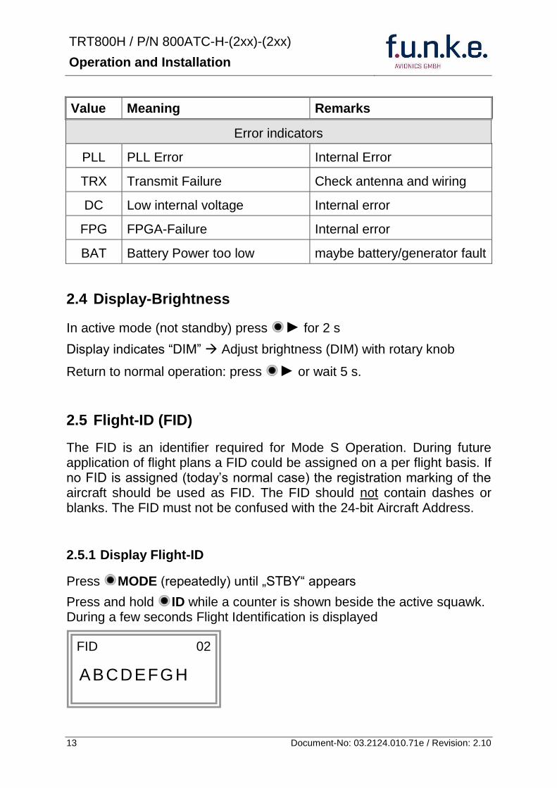
TRT800H PN 800ATC-H-(2xx)-(2xx)
Operation and Installation
14 Document-No 03212401071e Revision 210
252 Configure Flight-ID
Press MODE (repeatedly) until bdquoSTBYldquo appears
Press and hold ID while a counter is shown beside the active squawk Release ID when ldquoCHANGE FIDrdquo is displayed
Enter Flight-Id with cursor button and rotary knob
Press MODE to save and return to STBY
Please refer to section 454 for configuration of the 24-bit Address (AA) and Aircraft Category (AC)
26 Transponder Mode selection
Press MODE (repeatedly) to select from following Modes
STBY bdquoStandbyldquo Transponder does not respond to any interrogation Squitter and ADS-B output is not active
A C S bdquoMode A+C+Sldquo Standard condition transponder responds to mode A C and S interrogations
A ndash S bdquoMode A+S no Cldquo Altitude is not transmitted (neither on C nor on S requests) All other Mode-S data as well as Mode-A replies are transmitted
Enter FID left-aligned without any blanks or dashes () eg 12345621DEFAV for the marking D-EFAV The last remaining digits shall be filled with blanks
CHANGE FID
_ _ _ _ _ _ _ _ A B C D E F G H
- exit
TRT800H PN 800ATC-H-(2xx)-(2xx)
Operation and Installation
15 Document-No 03212401071e Revision 210
If no 24-bit address (AA) was defined or entered as ldquo000000ldquo the transponder operates as a Mode AC transponder in that case the following Modes are possible apart from Standby
A C ndash bdquoMode A+Cldquo Transponder replies only on Mode A and Mode-C interrogations
A ndash ndash bdquoMode Aldquo Transponder replies only on Mode A interrogations
In STBY (Standby) mode all transponder transmissions are disabled completely Therefore the transponder is not visible in this mode to air traffic control or the anti-collision systems onboard other aircrafts
Never use the STBY mode in flight unless you are requested to do so by air traffic control Always remember to put the transponder in active mode prior to take off
27 Squawk-Setting
The active Squawk is displayed in the upper line while the standby Squawk is presented at the lower line
Setting the Standby Squawk
Press to set the cursor (bdquo^ldquo) turn rotary knob to set numbers of the standby Squawk
Press to activate the Standby Squawk (this moves the current active Squawk into Standby)
28 VFR ndash Squawk
The transponder features a user-defined squawk code for VFR-flight (factory setting 7000)
Activate VFR-Squawk
Press VFR (bdquoVFRldquo is indicated) now the active Squawk is moved into Standby but not visible because the indication of the Standby Squawk is overlapped by bdquoVFRldquo
TRT800H PN 800ATC-H-(2xx)-(2xx)
Operation and Installation
16 Document-No 03212401071e Revision 210
Display Standby Squawk
Press VFR or or use the rotary knob (the VFR-Squawk remains active)
Example
VFR VFR
Now the Standby Squawk can be adjusted by using the rotary knob and activated with
In order to store the current active Squawk as new VFR-Squawk (replacing the factory setting 7000) Press and hold VFR until an bdquoSldquo is indicated (approx 3 s) after releasing the button bdquoVFRldquo is shown
29 ID ndash Special Position Identification (SPI) ldquoSquawk Identrdquo
Press ID to activate transmission of the special position identification pulse with every reply within 18 seconds ldquoIDTrdquo appears on the display
By pressing ID a special position identification pulse (SPI) is transmitted with every reply within 18 seconds which causes an accented marking on the Controllerrsquos screen The bdquoSpecial Position Identificationldquo has to be activated after the bdquoSquawk Identldquo request of the Controller
210 Error-Codes
Please refer to 23 Display - Indications for possible displayed errors
7000
FL 030
STBY 4700
7000
FL 030
STBY VFR
4700
FL 030
STBY 5600
TRT800H PN 800ATC-H-(2xx)-(2xx)
Operation and Installation
17 Document-No 03212401071e Revision 210
3 INSTALLATION
31 Notes
The following suggestions should be considered before installing
The assigned installation company will supply wiring For diagrams refer to 37 Wiring
Transponder External Memory all cables and antennas shall be installed according to bdquoFAA AC-14313-2A Acceptable Methods Techniques and Practices ndash Aircraft Alterationsldquo and the appropriate manufacturerrsquos instructions
32 Telecommunication data
Depending on your national telecommunications legislation the following data may be required when applying for the aircraft radio station license
Manufacturer funke AVIONICS GmbH
Type Designation TRT800H
EASA Number EASA21O269
Transmitter Power Output
126 W
Frequency 1090 MHz
Emission Designator 12M0M1D
33 Scope of Delivery
Item namenumber Description
TRT800H Transponder TRT800H
TRT800EMSS External Memory (Aircraft-Address-Adaptor with wiring)
M4X8ZSW (3 pieces) screw for panels up to 5 mm thickness
56S101A4 TNC antenna connector
03212401071e Manual bdquoOperation and Installationldquo
EASA Form 1
TRT800H PN 800ATC-H-(2xx)-(2xx)
Operation and Installation
18 Document-No 03212401071e Revision 210
34 Unpacking and Inspecting of the Equipment
Carefully unpack the equipment and inspect for transport damages If a damage claim has to be filed save the shipping container and all packing materials as evidence to your claim
35 Mounting
In cooperation with a maintenance shop location and kind of the installation are specified The maintenance shop can supply all cables Suitable sets of cables are available from funke AVIONICS GmbH
Select a position away from heat sources Provide space for adequate convection cooling
Leave sufficient space for the installation of cables and connectors
Avoid sharp bends and wiring close to control cables
Leave sufficient lead length for inspection or repair of the wiring of the connector (containing the memory) so that when the mounting hardware for the rear connectors is removed the assembly may be pulled forward several inches
Bend the harness at the rear connectors to inhibit water droplets (formed due to condensation) from collecting in the connector
For mounting detailsdrawing refer to chapter 3122 Mounting Advices
For storage or reshipment the original packaging should be used
TRT800H PN 800ATC-H-(2xx)-(2xx)
Operation and Installation
19 Document-No 03212401071e Revision 210
36 Equipment Connections
361 Electrical Connections
One 15 pin D-SUB miniature connector includes all electrical connections except for the antenna Use only an External Memory Adapter TRT800EMxx as this is part of the certification and includes a memory device in which the ICAO 24-bit Aircraft Address is stored
3611 Mutual Suppression
Other equipment on board (e g DME) may transmit in the same frequency band as the transponder
If such a device is installed a suppression wiring shall be installed in order to protect the receiving parts of the different devices from in-band transmissions
Mutual suppression is a synchronous pulse that is sent to the other equipment to suppress transmission of a competing transmitter for the duration of the pulse train transmission The transponder transmission may be suppressed by an external source and vice versa
To activate mutual suppression connect the SUPP_IO signal to the according signals of the other equipment
3612 Ground Switch
If an external Ground-Switch is connected to the transponder and activated in the setup the transponder can detect if the aircraft is airborne or on the ground This allows the transponder to automatically activate the Ground mode whenever the aircraft is on ground
In order to activate this feature the input bdquoFLY-GNDldquo must be connected to an external switch which connects the input pin with bdquoGNDldquo when the gear is weighted or remains open in the other case
This feature must additionally be activated in the Setup For details on configuration please refer to section 454
The (+UB)-wire has to protected by circuit breaker (2 Amp)
TRT800H PN 800ATC-H-(2xx)-(2xx)
Operation and Installation
20 Document-No 03212401071e Revision 210
3613 Auto-On
The Auto-On input allows to define how the transponder will behave when power is supplied to it
If the aircraft is equipped with a dedicated avionics master switch that switches the power supply to the transponder the pin Auto-On must be wired together with the UB+ pin to the avionic master switch The onoff button on the transponder is without function in that case The transponder will start automatically whenever power is supplied
On aircraft without such an avionics master switch the pin Auto-On must be left unconnected In this case the transponder must be switched on and off via the transponders onoff button on the front panel
362 Static Air Port
Install a silicon soft tube fitting the 5 mm static air hose at the backside of the transponder and secure plumbing with appropriate clamps
37 Wiring
371 Conductor Cross Section
Power Supply (Power GND) AWG20 (062 mmsup2)
Signals AWG22 (038 mmsup2)
The conductors must be approved for aircraft use
TRT800H PN 800ATC-H-(2xx)-(2xx)
Operation and Installation
21 Document-No 03212401071e Revision 210
372 Pin Assignment
The transponder may only be operated together with an external memory address adaptor TRT800EMxx
Pin Signal Remarks Adaptor
Typ(4)
TRT800
EM
Adaptor
Typ(4)
TRT800
EMSS
Adaptor Typ
TRT800
EMRS
1 GND -
2 Remote control(1) Input
3 EEPROM Signal TRT800EMxx internal
4 EEPROM Signal TRT800EMxx internal
5 TX RS-232 Serial Output
6 Switched +UB(1) Output
7 Remote control(1) Output
8 +UB power supply Input
9 GND -
10 EEPROM VCC TRT800EMxx internal
11 EEPROM GND TRT800EMxx internal
12 RX RS-232 Serial Input
13 Suppression Input Output
14 Auto-On(2) Input(2)
15 Fly-GND Switch(3) Input(3)
= in the plug and get out = in the plug and not get out ∕ = internal connection to the device
(1) SWITCHED +UB OUT Interface Remote control
May only be used for compatible funke AVIONICS devices Do not connect pins if interface is not used
(2) Auto-On Connect to +UB override front panel onoff button Leave unconnected to use front panel onoff button
(3) Ground Switch
FLY-GND
If an external Ground Switch is connected it must connect this pin to GND to indicate the on-ground condition Leave open otherwise
(4) Adaptors TRT800EM amp TRT800EMSS
Adaptor version does not provide full interface capability (see table for details)
TRT800H PN 800ATC-H-(2xx)-(2xx)
Operation and Installation
22 Document-No 03212401071e Revision 210
373 Cable plan External Memory EM800
3731 Cable plan TRT800EMRS (older version with interface remote)
to SN 90932013
DSUB 15pol
TRT800HTRT800A
lt PIN-5 gt
lt PIN-12gt
lt PIN-15gt
lt PIN-13gt
lt PIN-7 gt
lt PIN-2 gt
lt PIN-6 gt
lt PIN-1 gt
lt PIN-9 gt
lt PIN-8 gt
lt PIN-14gt
TXD
RXD
FLY_GND
SUPP_IO
GND
open
cable
ends
Remote Binder
Connector
female
white
black
yellow
red
shield
blue
red
brown
GND
+UB
AUTO-ON(2)(3)
black
white
red
yellow
shield
Binder Connector female
(solder side)
1 2 3 4 5 6 7 8
9 10 11 12 13 14 15
D-SUB Connector female
(solder side)
open
cable
ends
1 New interface available
-at TRT800H starting from SN 30430109 with SW V53
-at TRT800A starting with SW V53 2 New TRT800H interface starting from HW 60 3 port function not available at TRT800A
3
4 2
5 1
RMT-LIGHT
GND
RMT-TXD
RMT-SW+UB
RMT-RXD
RMT-TXD(1)
RMT-RXD(1)
RMT-SW+UB(2)(3)
RMT-LIGHT(2)
GND(1)
TRT800H PN 800ATC-H-(2xx)-(2xx)
Operation and Installation
23 Document-No 03212401071e Revision 210
3732 Cable plan TRT800EMRS (newer version with interface remote)
from SN 90932114
DSUB 15pol
TRT800HTRT800A
lt PIN-5 gt
lt PIN-12gt
lt PIN-15gt
lt PIN-13gt
lt PIN-7 gt
lt PIN-2 gt
lt PIN-6 gt
lt PIN-1 gt
lt PIN-9 gt
lt PIN-8 gt
lt PIN-14gt
TXD
RXD
FLY_GND
SUPP_IO
GND
open
cable
ends
Remote Binder
Connector
female
white
brown
yellow
green
shield
blue
red
brown
GND
+UB
AUTO-ON(2)(3)
brown
white
green
yellow
shield
Binder Connector female
(solder side)
1 2 3 4 5 6 7 8
9 10 11 12 13 14 15
D-SUB Connector female
(solder side)
open
cable
ends
1 New interface available
-at TRT800H starting from SN 30430109 with SW V53
-at TRT800A starting with SW V53 2 New TRT800H interface starting from HW 60 3 port function not available at TRT800A
3
4 2
5 1
RMT-LIGHT
GND
RMT-TXD
RMT-SW+UB
RMT-RXD
RMT-TXD(1)
RMT-RXD(1)
RMT-SW+UB(2)(3)
RMT-LIGHT(2)
GND(1)
TRT800H PN 800ATC-H-(2xx)-(2xx)
Operation and Installation
24 Document-No 03212401071e Revision 210
3733 Cable plan TRT800EMSS (newer version without interface remote)
from SN 91032115
The External ndash Memory ndash Address - Adapter TRT800EMxx contains electronic parts and must not be opened Opening or modifying the connector leads to the loss of airworthiness certification
DSUB 15pol
TRT800HTRT800A
lt PIN-5 gt
lt PIN-12gt
lt PIN-15gt
lt PIN-13gt
lt PIN-1 gt
lt PIN-9 gt
lt PIN-8 gt
lt PIN-14gt
TXD
RXD
FLY_GND
SUPP_IO
GND
open
cable
ends
white
brown
yellow
green
shield
blue
red
brown
GND
+UB
AUTO-ON(2)(3)
open
cable
ends
2 New TRT800H interface starting from HW 60 3 port function not available at TRT800A
1 2 3 4 5 6 7 8
9 10 11 12 13 14 15
D-SUB Connector female
(solder side)
TRT800H PN 800ATC-H-(2xx)-(2xx)
Operation and Installation
25 Document-No 03212401071e Revision 210
38 Antenna
381 Antenna Selection
Recommended antennas see section 311 Accessories
Choose an antenna type compatible with the vehicle and the mounting location
Specified features depend on proper installation of the antenna
The radiation pattern needs to be verified considering aircraft type and mounting location
The electrical interference between the antenna and any other equipment must be taken into account in such a way that no reduction of the performance of any other system will occur
Install only certified antennas
382 Installation Recommendation
Take note of the antenna manufacturerrsquos instructions
The usually deployed Dipole- or Blade antennas necessarily require a high frequency capable solid metal ground plane at the antenna base
For installation in composite aircrafts ground planes are to be added The ground plane should be as large as possible but in any case not smaller than 10 cm x 10 cm If in doubt please contact the aircraft manufacturer
Keep away three feet from any other antenna
Pursue mounting in vertical position under the belly in flight direction
383 Antenna Wiring
Suitable antenna cables see section 311 Accessories
Keep wiring as short as possible
The smallest cable bend radius is 10cm Avoid sharp bends
Keep away from an ADF antenna cable at least 12 inches
Electrical connections to the antenna shall be protected against moisture to avoid loss of efficiency
TRT800H PN 800ATC-H-(2xx)-(2xx)
Operation and Installation
26 Document-No 03212401071e Revision 210
39 Post-Installation Check
All steering and control functions of the aircraft are to be examined in order to exclude disturbances by the wiring
The most important factor in the transponder configuration is the setting of the ICAO address (see section 454)
Attenuation from antenna to transponder at 1090 MHz must not exceed 15 dB
A certified maintenance shop must verify proper operation of the transponder by testing in accordance with Appendix F of ldquo14 CFR Part 43 ndash ATC Transponder Tests and Inspectionsrdquo
TRT800H PN 800ATC-H-(2xx)-(2xx)
Operation and Installation
27 Document-No 03212401071e Revision 210
310 Starting Up
Turn the transponder on with IO After start-up the following screens appear
311 Accessories
Part Number Description
TRKABEL1 Antenna cable 10 m (32 ft) TNC BNC
TRKABEL2 Antenna cable 25 m (82 ft) TNC BNC
TRKABEL3 Antenna cable 40 m (132 ft) TNC BNC
TRKABEL4 Antenna cable 65 m (213 ft) TNC BNC
TRT800EMRS External-Memory (Aircraft-Address-Adaptor) Connection cable with interface TRT-Remote control
CI-105 TransponderDME Antenna TSO C66b C74c
CI105 Comant Industries Inc
Height 325rdquo Weight 90 g (02 lbs)
AV22 Transponder Rod antenna TSO C74c
AV-22 R A Miller Industries
The TRT800H starts in standby mode (indicated with STBY) In order to change into operational mode (indicated with ACS) press MODE If ground switch is connected and status ldquoin flightrdquo is selected TRT800H starts in active mode
Very important is the correct configuration of the 24bit Aircraft-Address (see 454 General Setup)
TRT800H V53
FPGA-Vers 102
2000 FL 030
STBY 7000
TRT800H PN 800ATC-H-(2xx)-(2xx)
Operation and Installation
28 Document-No 03212401071e Revision 210
312 Drawings
3121 Dimensions
20mm15 mm
170 mm
TRT800TRT800H
65 mm
65
mm
Oslash 57 mm
Static Air
Antenna
PowerRS232
3122 Mounting Advices
Connections Area
8
0 m
m
Panel Cut-out
470 mm
470
mm
575 mm
4 x Oslash 4 mm
Oslash
Connector (plug) has to be clamped with both spring locks
No screws may be turned in more than max 15mm into the device ndash even if no hard limit is noticeable
Fixing clips (spring) left right
TRT800H PN 800ATC-H-(2xx)-(2xx)
Operation and Installation
29 Document-No 03212401071e Revision 210
4 TRANSPONDER SETTINGS
41 Overview
The TRT800H is capable of storing the following information
ICAO 24-Bit Aircraft-Address (AA)
Aircraft Category (AC)
Flight Identification (FID)
Ground-Switch (YesNo)
Speed Category (RI)
RS232 Interface Configuration
All of these data are configurable in the Setup and are stored in the external memory module integrated within the housing of the D-Sub connector (included in the delivery)
The cable with this connector shall remain in the aircraft even if the unit is removed to ensure that the ICAO 24bit aircraft address is fixed to the aircraft
Additionally the following usertransponder related settings are stored transponder internally
Active Squawk
Passive Squawk
VFR Squawk
Altitude offset
Display brightness
42 Display Configuration Summary
Transponder provides the opportunity to show summary of complete current settings To access configuration summary pages push and hold
ID in Standby mode Release ID if ldquoSHOW SETUPrdquo is displayed The summary is subdivided into the following pages
TRT800H PN 800ATC-H-(2xx)-(2xx)
Operation and Installation
30 Document-No 03212401071e Revision 210
Page 1
Aircraft Address
Aircraft Category
Flight Identification
MODE
Page 2 Speed Category
Ground Switch option
Remote Header option
MODE
Page 3 RS-232 Settings
Protocol baud rate position (if available)1
MODE
Page 4 Altitude correction settings
(part 1)
MODE
Page 5 Altitude correction settings
(part 2)
Note 1 Position data will only be displayed if
a GPS protocol is set as interface protocol (NMEA FREEFLIGHT AR-NAV)
18000 ft 0ft 25000 ft + 100ft 35000 ft - 50ft
exit
ALTITUDE CORRECTION 2000 ft 0ft 10000 ft + 100ft next
RS-232 NMEA Baud 4800 Pos 481 99 next
Speed Cat 8 Ground Sw YES Remote Hd NO next
AA F E 1 2 3 4 AC 1 9 FID 4 4 E 1 2 3 next
TRT800H PN 800ATC-H-(2xx)-(2xx)
Operation and Installation
31 Document-No 03212401071e Revision 210
GPS receiver is connected and transmits data (if not ldquoPos no datardquo is displayed)
a valid position is transmitted (if not ldquoPos wrong datardquo is displayed)
While configuration summary page is displayed no new position data will be processed
43 General settings
431 ICAO 24-Bit Aircraft Address (AA)
Ask your national aviation authority (e g in Germany LBA Referat B5 Department ldquoVerkehrszulassungrdquo) how to obtain the AA In the case of aerial sports equipment the contact point would be the respective associations Only the assigned AA has to be used and must not be modified at any time because a duplicate address would jeopardize the data surveillance and integrity figures of Mode S
If no AA is stored after power on the display shows ldquoCRADLE OFFrdquo and the transponder operates in Mode AC
(Configuration of the AA see section 454)
432 Aircraft Category (AC)
Code Description Code Description
11 Emergency Vehicle 1C Ultra-Light Paraglider
12 Service Vehicle 1E Drone
19 Glider 21 Aircraft (D-Exxx) lt 15500 lbs Motor Glider (D-Kxxx)
1A Balloon amp Airship 22 Aircraft ge 15500 lbslt 75000 lbs
1B Paratrooper 27 Rotorcraft
Only one of the Codes mentioned in the table above must be used
Setuprarr454
Setuprarr454
TRT800H PN 800ATC-H-(2xx)-(2xx)
Operation and Installation
32 Document-No 03212401071e Revision 210
433 Flight-ID (FID)
Per ICAO regulation Mode-S data must contain a valid flight identification (FID) to ensure that the correlation between flight plan and radar data will work automatically
FID setting is required to correspond to the aircraft identification that has been specified at item 7 of the ICAO flight plan It contains seven characters at a maximum (left-aligned no additional zeros dashes or spacesblanks)
For an aircraft using a company call sign the Flight-ID mostly consists of the ICAO three-letter designator for the aircraft operator followed by an identification code eg KLM511 BAW213 JTR25
If no company call sign is used or no flight plan is filed the default FID to be set consists of the registration marking of the aircraft (eg DEABC) with no dashes spacesblanks or additional zeros even if they are included in the registration marking on the aircraft (tail number) While entering the FID into the transponder the last remaining digits must be filled with blanks
The ICAO Flight Plan only specifies 7 characters for FID funke AVIONICS reserves 8 characters as stated in ED-73B for further expansion of the flight plan
The user shall only program 7 characters for FID
Setuprarr454
TRT800H PN 800ATC-H-(2xx)-(2xx)
Operation and Installation
33 Document-No 03212401071e Revision 210
434 Reply Information - Speed Category (RI)
Besides AA AC and FID another important part of the Mode-S data is the Speed Category of the respective aircraft This speed category shall be configured in the setup and must contain one of the following codes
Code Description
08 No maximum airspeed data available
09 Maximum airspeed le 75 kt
10 75 kt gt maximum airspeed le 150 kt
11 150 kt gt maximum airspeed le 300 kt
12 300 kt gt maximum airspeed le 600 kt
13 600 kt gt maximum airspeed le 1200 kt
14 Maximum airspeed gt 1200 kt
15 Not assigned
44 Optional settings
441 Option Ground-Switch
If a ground switch is connected (and enabled in setup) the transponder is able to determine on-ground and in-flight state On-ground state is activated automatically once the gear touches the ground On-ground state is indicated on display by symbol G (apart from lsquoFrsquo for In-flight-state)
In On-ground-state the transponder will reply differently to certain addressed interrogations Also the transmission rate of some periodically sent data (squitters ADS-B) is reduced This allows ATC to distinguish between airborne aircraft and those on the ground and it reduces the Mode S channel load
For small aircraft authorities normally do not require such a ground switch In this case the transponder will use the same data formats on the ground as in the airborne state
Setuprarr454 Wiringrarr373
Setuprarr454
TRT800H PN 800ATC-H-(2xx)-(2xx)
Operation and Installation
34 Document-No 03212401071e Revision 210
442 Option Remote Header
The transponder provides a TRT800RT remote control interface If a remote header TRT800RT is connected transponder can be remote controlled via this interface Remote interface provides control of all standard user inputs available during standard operational mode For more information see TRT800RT manual Remote control interface de-activation is setup configurable Remote control interface must only be connected to TRT800RT
443 Serial Interface (RS232)
Using serial interface a GPS receiver can be connected to broadcast own position via ADS-B Out position message Position could be received by other appropriately equipped aircrafts and processed for collision avoidance ADS-B Out functionality
The ADS-B function of this device has not been evaluated during the FAA TSO certification process other than to ensure non-interference Due to the SW assurance of DAL D the ADS-B function cannot be used in the US National Airspace Connecting a GPS source will not comply to FAA certification requirements with regard to ADS-B
Supported formatsprotocols are
Option Description Baud rate
FREEFLIGHT GPSWAAS Sensor 1201
NexNav NNL 3101
19200
AR-NAV Bendix King
KLN 89B KLN 94 ldquoStandard RS232 Sentencerdquo
KMD 150 ldquoSentence Type 1rdquo
Garmin 400 Series ldquoSentence Type 1rdquo (with and without altitude data)
9600
NMEA NMEA-Format data format RMC is expected
4800
Setuprarr454 Wiringrarr373
Setuprarr454 Wiringrarr373
TRT800H PN 800ATC-H-(2xx)-(2xx)
Operation and Installation
35 Document-No 03212401071e Revision 210
Option Description Baud rate
FAVISIA Glass Cockpit support
FAVISIA Data format to be processed in FAVISIA avionics suite
-
FAVISIA+GPS Data format to be processed in FAVISIA avionics suite (output) and additional processing of incoming NMEA GPS-Receiver position data to support the ADS-B Out functionality
4800
Other
Comm-AB-support
Data format for special purpose An additional data link processor allows COMM-AB operation and processing of the position information of a flight management system simultaneously
38400
Disabled No communication via RS232 interface -
444 Altitude CorrectionOffset
The TRT800H has an integrated temperature compensated high-precision pressure sensor This sensor is factory-calibrated so that it will yield accurate flight level (uncorrected pressure altitude) within the entire altitude range
However due to differences in calibration of the TRT800H pressure sensor and the altimeter in the cockpit it may become necessary to adjust the TRT800H pressure readings so that the value indicated and transmitted by the TRT800H corresponds to the indication of the primary altimeter seen by the pilot within 125 feet (as specified in ETSO C88aSAE AS 8003)
Setting for all described GPS-systems
1 2 position messages per 2 sec
Setuprarr455
TRT800H PN 800ATC-H-(2xx)-(2xx)
Operation and Installation
36 Document-No 03212401071e Revision 210
The check for correspondence between the primary altimeter and the TRT800H is usually performed every 24 months as part of the aircrafts altimeter checks
Altitude correction is based on setup configurable offset values at five interpolation points ( 2000 8000 18000 25000 and 35000 ft)The offset value itself is limited to a range from -100 to + 100ft at each point (10ft steps)
45 Setup Procedure
Programming of the ICAOA 24-bit Aircraft Address and of the Aircraft Category shall be executed by qualified personnel only
A wrong Aircraft Address or Flight ID may cause serious problems ATC or with ACASTCAS systems
Pilot and owner are responsible for correctly set transponder data
451 Setup Menu Control
In order to access the functions described in the following paragraphs push and hold ID in Standby mode Release ID if desired counter value menu name is displayed to enter the menu The following menu entries are selectable
Count Displayed Name Function
03 FID FID is displayed
48 CHANGE FID Enter FID setup page
913 SHOW SETUP Enter setup summary listed on different pages (no changes possible)
2528 ENTER SETUP Enter transponder general configuration pages
3134 ALTITUDE CORRECTION
Enter altitude correction menu
TRT800H PN 800ATC-H-(2xx)-(2xx)
Operation and Installation
37 Document-No 03212401071e Revision 210
452 Transponder configurationrecord structure
Aircraft related parts of transponder configuration are stored in one out of eight possible records (record=presetting) Each record contains the following information
Aircraft Address (AA 24bit)
Aircraft category (AC)
Flight identification (FID 6-8 numbersletters)
RS-232 Interface setting (eg GPS protocol)
Ground-Switch setting (Installed YesNo)
Speed category (RI) of the respective aircraft
Remote Header setting (Installed YesNo)
User related settings (eg squawk codes display brightness) are stored once in one global record (transponder internally)
453 Transponder configurationrecord handling
At least one record is stored in external memory Up to 8 records can be additional be applied during setup process
If more than one record is applied the active record must be selected out of a list (determined by FID) during start-up of the transponder
Previously applied records can be deleted again by filling FID with zerorsquos only
454 General Setup
Any menu item can be passed by MODE If no changes are made the original settings will remain stored Modification of one menu item does not impact the others No entries will be deleted
TRT800H PN 800ATC-H-(2xx)-(2xx)
Operation and Installation
38 Document-No 03212401071e Revision 210
Step Display (Example)
1 Start-up Transponder
2 Ensure the transponder-mode is bdquoSTBYldquo If necessary change the mode by pressing MODE
3 Press ID A counter is shown at the upper-right corner Hold ID till ldquoENTER SETUPrdquo is displayed
4 After release of ID the first setup menu is displayed
5 helliphellipselect position (^)
rotary knobchange value
MODE
6 With the rotary knob you can select bdquoyesldquo if a Ground Switch is installed if not select ldquonordquo and proceed with step 7
MODE
Record 1
GND Switch YesNo
next
AA EF123456
AC 18
FID ^BCDEFG
next
AA EF123456
AC 18
FID ABCDEFG
next
ENTER SETUP 26
2000 FL 030
STBY 7000
TRT800H PN 800ATC-H-(2xx)-(2xx)
Operation and Installation
39 Document-No 03212401071e Revision 210
Step Display (Example)
7 At this stage the respective speed category shall be selected by using the rotary knob
MODE
8 At this stage a GPS receiver for ADS-B Out can be selected (Selectable by rotary knob)
MODE
9 At this stage remote interface for communication between TRT800H and remote header can be activated (Selectable by rotary knob)
Remote interface must only be activated if a remote header is connected
MODE
10 With ID further Records can now be created and configured as described in the aforementioned steps At start-up of the transponder one of the defined records with all associated configurations need to be selected
MODE
Records ID=Edit Records
EXIT
Record 1
REMOTE Header YesNo
next
Record 1
GPSINTEXT NMEA
next
Record 1
Speed Cat 08-15
next
TRT800H PN 800ATC-H-(2xx)-(2xx)
Operation and Installation
40 Document-No 03212401071e Revision 210
Step Display (Example)
11 You have now left the configuration mode and are back in normal operation
12 Switch off the transponder
13 Switch on the transponder Your ICAO 24-Bit Aircraft Address is now stored
TRT800H V53
FPGA-Vers 102
2000 FL 030
STBY 7000
TRT800H PN 800ATC-H-(2xx)-(2xx)
Operation and Installation
41 Document-No 03212401071e Revision 210
455 Altitude Correction Setup
Altitude correction setup shall be executed by qualified personnel only
Pilot and owner are responsible for correctly set altitude offset values
The usesetting of altitude correction values is only necessary in exceptional cases (see 444 for details)
Altitude correction is based on five interpolation points ( 2000 10000 18000 25000 and 35000 ft)The offset value at each interpolation point can be adjusted in a range from -100 to + 100ft at each point (10ft steps) Offset values set to zero at each interpolation point deactivates altitude correction (defaultfactory setting)
Step Display (Example)
1 Start-up Transponder
2 Ensure the transponder-mode is bdquoSTBYldquo If necessary change the mode by pressing MODE
3 Press ID A counter is shown at the upper-right corner Hold ID till ldquoALTITUDE OFFSETrdquo is displayed
ALTITUDE OFFSET 33
2000 FL 030
STBY 7000
Descriptionrarr444
TRT800H PN 800ATC-H-(2xx)-(2xx)
Operation and Installation
42 Document-No 03212401071e Revision 210
Step Display (Example)
4 After release of ID the first altitude level + corresponding offset value is displayed
5 Change offset value with rotary knob
MODE
6 (9) Repeat last step for another 4 altitude levels 10000ft 18000ft 25000ft 35000ft
MODE
10 You have now left the configuration mode and are back in normal operation
Switch off the transponder
11 Switch on the transponder New altitude offset values will now be used for altitude calculation
Altitude 10000 ft
Offset 0 ft
nextexit
Altitude 2000 ft
Offset 0 ft
next
TRT800H V53
FPGA-Vers 102
2000 FL 030
STBY 7000
Altitude 2000 ft
Offset 0 ft
next
TRT800H PN 800ATC-H-(2xx)-(2xx)
Operation and Installation
43 Document-No 03212401071e Revision 210
5 APPENDIX
51 Technical Data
Compliance CS-ETSO-2C112a
EASA21O269
FAA TSO-C112c
Applicable Documents CS-ETSO-2C112a
FAA TSO-C112c
EUROCAE ED-73C Class 1 Level 2es
RTCA DO-181D Class 1 Level 2es
EUROCAE ED-26
RTCA DO-160D
RTCA DO-178B Software-Level D
Temperature Ranges
Operation -20 degC to +55 degC for 30 min +70degC
Storage -55 degC to +85 degC
Altitude Range le 35 000 ft
Speed Range le 250 kt (TAS)
Shock 6 G Operation
20 G crash safety
Environmental Categories RTCA DO-160D EnvCat [C1Z]CAA[SM]XXXXXXZBAAA[TT]M[B3F3]XXA
Power Supply 138 VDC (10 VDC 16 VDC)
040 A 138 VDC (typ)
070 A 138 VDC (max)
10 W (max)
TRT800H PN 800ATC-H-(2xx)-(2xx)
Operation and Installation
44 Document-No 03212401071e Revision 210
Fuse External 2A-slow-blow fuse
Mounting Panel cut-out d=575 mm
Weight 06 kg (132 lbs)
Receiver Characteristics
Sensitivity
RF input power level resulting in a 90 reply rate
A MTL for ATCRBS and ATCRBSMode S All-Call interrogations -74 dBm plusmn3 dB
B MTL for Mode S interrogations -74 dBm plusmn 3 dB
Reply transmission frequency
1090 plusmn 1 MHz
RF Peak Power Output 21 dBW (126 W) at antenna base (with maximum cable attenuation of 15 dB)
Squitter (ADS-B) transmitted at random intervals uniformly distributed over the range from 08 to 12 seconds full self-verification of data and occurrence
Mode S Elementary Surveillance
ICAO 24-bit Aircraft Address (Hex-Code)
aircraft address as assigned by national aviation authority
FID Flight ID Flight Plan call sign or aircraft registration marking
Capability Report Reports the available data and means by which the transponder can report
Pressure Altitude Up to 35 000 ft in 25 ft increments
Flight Status in-flight on-ground
Mode S Enhanced Surveillance
Level 2es Comm-A Comm-B 56112-Bit-Messages
SI-capability
TRT800H PN 800ATC-H-(2xx)-(2xx)
Operation and Installation
45 Document-No 03212401071e Revision 210
52 Environmental Conditions
Characteristic DOndash160D Section Cat Condition
Temperature Altitude 40
C1
Low ground survival temperature
451 ndash 55degC
Low operating temperature 451 ndash 20degC
High ground survival Temperature
452 + 85degC
High Short-time Operating Temperature
452 + 70degC
High Operating Temperature 453 + 55degC
In-Flight Loss of Cooling 454 Z No auxiliary cooling required
Altitude 461 C1 35 000 ft
Temperature Variation 50 C 2degC change rate minimum per minute
Humidity 60 A
Shock 70 A
6 G operational shocks
20 G Crash Safety
Test Type R in all 6 directions
Vibration 80 S Vibration Curve M
Explosion Proofness 90 X No test required
Water Proofness 100 X No test required
Fluids Susceptibilities 110 X No test required
Sand and Dust 120 X No test required
Fungus Resistance 130 X No test required
Salt Spray 140 X No test required
Magnetic Effect 150 Z Less than 03 m
Power Input (DC) 160 B
Voltage Spike Conducted 170 A
Audio Frequency Conducted Susceptibility
180 A
TRT800H PN 800ATC-H-(2xx)-(2xx)
Operation and Installation
46 Document-No 03212401071e Revision 210
Characteristic DOndash160D Section Cat Condition
Induced Signal Susceptibility 190 A
Radio Frequency Susceptibility
200 TT
Emission of RF Energy 210 M
Lightning Induced Transient Susceptibility
220 B3F3
Lightning Direct Effects 230 X No test required
Icing 240 X No test required
Electrostatic Discharge (ESD) 250 A
53 DO-178B Open Problem Reports
There are no open problem reports for the software of this device
TRT800H PN 800ATC-H-(2xx)-(2xx)
Operation and Installation
47 Document-No 03212401071e Revision 210
Notes
f funke funke means ndash fabrication utilities network know-how engineering
funke AVIONICS GmbH Heinz-Strachowitz-Str 4
DE-86807 Buchloe Germany
phone +49-8241 80066 0
fax +49-8241 80066 99 E-mail
servicefunkeavionicsde wwwfunkeavionicsde
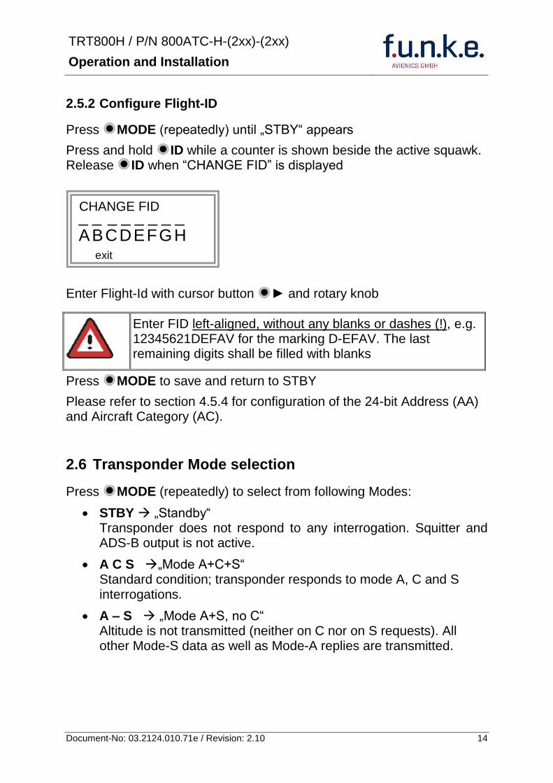
TRT800H PN 800ATC-H-(2xx)-(2xx)
Operation and Installation
15 Document-No 03212401071e Revision 210
If no 24-bit address (AA) was defined or entered as ldquo000000ldquo the transponder operates as a Mode AC transponder in that case the following Modes are possible apart from Standby
A C ndash bdquoMode A+Cldquo Transponder replies only on Mode A and Mode-C interrogations
A ndash ndash bdquoMode Aldquo Transponder replies only on Mode A interrogations
In STBY (Standby) mode all transponder transmissions are disabled completely Therefore the transponder is not visible in this mode to air traffic control or the anti-collision systems onboard other aircrafts
Never use the STBY mode in flight unless you are requested to do so by air traffic control Always remember to put the transponder in active mode prior to take off
27 Squawk-Setting
The active Squawk is displayed in the upper line while the standby Squawk is presented at the lower line
Setting the Standby Squawk
Press to set the cursor (bdquo^ldquo) turn rotary knob to set numbers of the standby Squawk
Press to activate the Standby Squawk (this moves the current active Squawk into Standby)
28 VFR ndash Squawk
The transponder features a user-defined squawk code for VFR-flight (factory setting 7000)
Activate VFR-Squawk
Press VFR (bdquoVFRldquo is indicated) now the active Squawk is moved into Standby but not visible because the indication of the Standby Squawk is overlapped by bdquoVFRldquo
TRT800H PN 800ATC-H-(2xx)-(2xx)
Operation and Installation
16 Document-No 03212401071e Revision 210
Display Standby Squawk
Press VFR or or use the rotary knob (the VFR-Squawk remains active)
Example
VFR VFR
Now the Standby Squawk can be adjusted by using the rotary knob and activated with
In order to store the current active Squawk as new VFR-Squawk (replacing the factory setting 7000) Press and hold VFR until an bdquoSldquo is indicated (approx 3 s) after releasing the button bdquoVFRldquo is shown
29 ID ndash Special Position Identification (SPI) ldquoSquawk Identrdquo
Press ID to activate transmission of the special position identification pulse with every reply within 18 seconds ldquoIDTrdquo appears on the display
By pressing ID a special position identification pulse (SPI) is transmitted with every reply within 18 seconds which causes an accented marking on the Controllerrsquos screen The bdquoSpecial Position Identificationldquo has to be activated after the bdquoSquawk Identldquo request of the Controller
210 Error-Codes
Please refer to 23 Display - Indications for possible displayed errors
7000
FL 030
STBY 4700
7000
FL 030
STBY VFR
4700
FL 030
STBY 5600
TRT800H PN 800ATC-H-(2xx)-(2xx)
Operation and Installation
17 Document-No 03212401071e Revision 210
3 INSTALLATION
31 Notes
The following suggestions should be considered before installing
The assigned installation company will supply wiring For diagrams refer to 37 Wiring
Transponder External Memory all cables and antennas shall be installed according to bdquoFAA AC-14313-2A Acceptable Methods Techniques and Practices ndash Aircraft Alterationsldquo and the appropriate manufacturerrsquos instructions
32 Telecommunication data
Depending on your national telecommunications legislation the following data may be required when applying for the aircraft radio station license
Manufacturer funke AVIONICS GmbH
Type Designation TRT800H
EASA Number EASA21O269
Transmitter Power Output
126 W
Frequency 1090 MHz
Emission Designator 12M0M1D
33 Scope of Delivery
Item namenumber Description
TRT800H Transponder TRT800H
TRT800EMSS External Memory (Aircraft-Address-Adaptor with wiring)
M4X8ZSW (3 pieces) screw for panels up to 5 mm thickness
56S101A4 TNC antenna connector
03212401071e Manual bdquoOperation and Installationldquo
EASA Form 1
TRT800H PN 800ATC-H-(2xx)-(2xx)
Operation and Installation
18 Document-No 03212401071e Revision 210
34 Unpacking and Inspecting of the Equipment
Carefully unpack the equipment and inspect for transport damages If a damage claim has to be filed save the shipping container and all packing materials as evidence to your claim
35 Mounting
In cooperation with a maintenance shop location and kind of the installation are specified The maintenance shop can supply all cables Suitable sets of cables are available from funke AVIONICS GmbH
Select a position away from heat sources Provide space for adequate convection cooling
Leave sufficient space for the installation of cables and connectors
Avoid sharp bends and wiring close to control cables
Leave sufficient lead length for inspection or repair of the wiring of the connector (containing the memory) so that when the mounting hardware for the rear connectors is removed the assembly may be pulled forward several inches
Bend the harness at the rear connectors to inhibit water droplets (formed due to condensation) from collecting in the connector
For mounting detailsdrawing refer to chapter 3122 Mounting Advices
For storage or reshipment the original packaging should be used
TRT800H PN 800ATC-H-(2xx)-(2xx)
Operation and Installation
19 Document-No 03212401071e Revision 210
36 Equipment Connections
361 Electrical Connections
One 15 pin D-SUB miniature connector includes all electrical connections except for the antenna Use only an External Memory Adapter TRT800EMxx as this is part of the certification and includes a memory device in which the ICAO 24-bit Aircraft Address is stored
3611 Mutual Suppression
Other equipment on board (e g DME) may transmit in the same frequency band as the transponder
If such a device is installed a suppression wiring shall be installed in order to protect the receiving parts of the different devices from in-band transmissions
Mutual suppression is a synchronous pulse that is sent to the other equipment to suppress transmission of a competing transmitter for the duration of the pulse train transmission The transponder transmission may be suppressed by an external source and vice versa
To activate mutual suppression connect the SUPP_IO signal to the according signals of the other equipment
3612 Ground Switch
If an external Ground-Switch is connected to the transponder and activated in the setup the transponder can detect if the aircraft is airborne or on the ground This allows the transponder to automatically activate the Ground mode whenever the aircraft is on ground
In order to activate this feature the input bdquoFLY-GNDldquo must be connected to an external switch which connects the input pin with bdquoGNDldquo when the gear is weighted or remains open in the other case
This feature must additionally be activated in the Setup For details on configuration please refer to section 454
The (+UB)-wire has to protected by circuit breaker (2 Amp)
TRT800H PN 800ATC-H-(2xx)-(2xx)
Operation and Installation
20 Document-No 03212401071e Revision 210
3613 Auto-On
The Auto-On input allows to define how the transponder will behave when power is supplied to it
If the aircraft is equipped with a dedicated avionics master switch that switches the power supply to the transponder the pin Auto-On must be wired together with the UB+ pin to the avionic master switch The onoff button on the transponder is without function in that case The transponder will start automatically whenever power is supplied
On aircraft without such an avionics master switch the pin Auto-On must be left unconnected In this case the transponder must be switched on and off via the transponders onoff button on the front panel
362 Static Air Port
Install a silicon soft tube fitting the 5 mm static air hose at the backside of the transponder and secure plumbing with appropriate clamps
37 Wiring
371 Conductor Cross Section
Power Supply (Power GND) AWG20 (062 mmsup2)
Signals AWG22 (038 mmsup2)
The conductors must be approved for aircraft use
TRT800H PN 800ATC-H-(2xx)-(2xx)
Operation and Installation
21 Document-No 03212401071e Revision 210
372 Pin Assignment
The transponder may only be operated together with an external memory address adaptor TRT800EMxx
Pin Signal Remarks Adaptor
Typ(4)
TRT800
EM
Adaptor
Typ(4)
TRT800
EMSS
Adaptor Typ
TRT800
EMRS
1 GND -
2 Remote control(1) Input
3 EEPROM Signal TRT800EMxx internal
4 EEPROM Signal TRT800EMxx internal
5 TX RS-232 Serial Output
6 Switched +UB(1) Output
7 Remote control(1) Output
8 +UB power supply Input
9 GND -
10 EEPROM VCC TRT800EMxx internal
11 EEPROM GND TRT800EMxx internal
12 RX RS-232 Serial Input
13 Suppression Input Output
14 Auto-On(2) Input(2)
15 Fly-GND Switch(3) Input(3)
= in the plug and get out = in the plug and not get out ∕ = internal connection to the device
(1) SWITCHED +UB OUT Interface Remote control
May only be used for compatible funke AVIONICS devices Do not connect pins if interface is not used
(2) Auto-On Connect to +UB override front panel onoff button Leave unconnected to use front panel onoff button
(3) Ground Switch
FLY-GND
If an external Ground Switch is connected it must connect this pin to GND to indicate the on-ground condition Leave open otherwise
(4) Adaptors TRT800EM amp TRT800EMSS
Adaptor version does not provide full interface capability (see table for details)
TRT800H PN 800ATC-H-(2xx)-(2xx)
Operation and Installation
22 Document-No 03212401071e Revision 210
373 Cable plan External Memory EM800
3731 Cable plan TRT800EMRS (older version with interface remote)
to SN 90932013
DSUB 15pol
TRT800HTRT800A
lt PIN-5 gt
lt PIN-12gt
lt PIN-15gt
lt PIN-13gt
lt PIN-7 gt
lt PIN-2 gt
lt PIN-6 gt
lt PIN-1 gt
lt PIN-9 gt
lt PIN-8 gt
lt PIN-14gt
TXD
RXD
FLY_GND
SUPP_IO
GND
open
cable
ends
Remote Binder
Connector
female
white
black
yellow
red
shield
blue
red
brown
GND
+UB
AUTO-ON(2)(3)
black
white
red
yellow
shield
Binder Connector female
(solder side)
1 2 3 4 5 6 7 8
9 10 11 12 13 14 15
D-SUB Connector female
(solder side)
open
cable
ends
1 New interface available
-at TRT800H starting from SN 30430109 with SW V53
-at TRT800A starting with SW V53 2 New TRT800H interface starting from HW 60 3 port function not available at TRT800A
3
4 2
5 1
RMT-LIGHT
GND
RMT-TXD
RMT-SW+UB
RMT-RXD
RMT-TXD(1)
RMT-RXD(1)
RMT-SW+UB(2)(3)
RMT-LIGHT(2)
GND(1)
TRT800H PN 800ATC-H-(2xx)-(2xx)
Operation and Installation
23 Document-No 03212401071e Revision 210
3732 Cable plan TRT800EMRS (newer version with interface remote)
from SN 90932114
DSUB 15pol
TRT800HTRT800A
lt PIN-5 gt
lt PIN-12gt
lt PIN-15gt
lt PIN-13gt
lt PIN-7 gt
lt PIN-2 gt
lt PIN-6 gt
lt PIN-1 gt
lt PIN-9 gt
lt PIN-8 gt
lt PIN-14gt
TXD
RXD
FLY_GND
SUPP_IO
GND
open
cable
ends
Remote Binder
Connector
female
white
brown
yellow
green
shield
blue
red
brown
GND
+UB
AUTO-ON(2)(3)
brown
white
green
yellow
shield
Binder Connector female
(solder side)
1 2 3 4 5 6 7 8
9 10 11 12 13 14 15
D-SUB Connector female
(solder side)
open
cable
ends
1 New interface available
-at TRT800H starting from SN 30430109 with SW V53
-at TRT800A starting with SW V53 2 New TRT800H interface starting from HW 60 3 port function not available at TRT800A
3
4 2
5 1
RMT-LIGHT
GND
RMT-TXD
RMT-SW+UB
RMT-RXD
RMT-TXD(1)
RMT-RXD(1)
RMT-SW+UB(2)(3)
RMT-LIGHT(2)
GND(1)
TRT800H PN 800ATC-H-(2xx)-(2xx)
Operation and Installation
24 Document-No 03212401071e Revision 210
3733 Cable plan TRT800EMSS (newer version without interface remote)
from SN 91032115
The External ndash Memory ndash Address - Adapter TRT800EMxx contains electronic parts and must not be opened Opening or modifying the connector leads to the loss of airworthiness certification
DSUB 15pol
TRT800HTRT800A
lt PIN-5 gt
lt PIN-12gt
lt PIN-15gt
lt PIN-13gt
lt PIN-1 gt
lt PIN-9 gt
lt PIN-8 gt
lt PIN-14gt
TXD
RXD
FLY_GND
SUPP_IO
GND
open
cable
ends
white
brown
yellow
green
shield
blue
red
brown
GND
+UB
AUTO-ON(2)(3)
open
cable
ends
2 New TRT800H interface starting from HW 60 3 port function not available at TRT800A
1 2 3 4 5 6 7 8
9 10 11 12 13 14 15
D-SUB Connector female
(solder side)
TRT800H PN 800ATC-H-(2xx)-(2xx)
Operation and Installation
25 Document-No 03212401071e Revision 210
38 Antenna
381 Antenna Selection
Recommended antennas see section 311 Accessories
Choose an antenna type compatible with the vehicle and the mounting location
Specified features depend on proper installation of the antenna
The radiation pattern needs to be verified considering aircraft type and mounting location
The electrical interference between the antenna and any other equipment must be taken into account in such a way that no reduction of the performance of any other system will occur
Install only certified antennas
382 Installation Recommendation
Take note of the antenna manufacturerrsquos instructions
The usually deployed Dipole- or Blade antennas necessarily require a high frequency capable solid metal ground plane at the antenna base
For installation in composite aircrafts ground planes are to be added The ground plane should be as large as possible but in any case not smaller than 10 cm x 10 cm If in doubt please contact the aircraft manufacturer
Keep away three feet from any other antenna
Pursue mounting in vertical position under the belly in flight direction
383 Antenna Wiring
Suitable antenna cables see section 311 Accessories
Keep wiring as short as possible
The smallest cable bend radius is 10cm Avoid sharp bends
Keep away from an ADF antenna cable at least 12 inches
Electrical connections to the antenna shall be protected against moisture to avoid loss of efficiency
TRT800H PN 800ATC-H-(2xx)-(2xx)
Operation and Installation
26 Document-No 03212401071e Revision 210
39 Post-Installation Check
All steering and control functions of the aircraft are to be examined in order to exclude disturbances by the wiring
The most important factor in the transponder configuration is the setting of the ICAO address (see section 454)
Attenuation from antenna to transponder at 1090 MHz must not exceed 15 dB
A certified maintenance shop must verify proper operation of the transponder by testing in accordance with Appendix F of ldquo14 CFR Part 43 ndash ATC Transponder Tests and Inspectionsrdquo
TRT800H PN 800ATC-H-(2xx)-(2xx)
Operation and Installation
27 Document-No 03212401071e Revision 210
310 Starting Up
Turn the transponder on with IO After start-up the following screens appear
311 Accessories
Part Number Description
TRKABEL1 Antenna cable 10 m (32 ft) TNC BNC
TRKABEL2 Antenna cable 25 m (82 ft) TNC BNC
TRKABEL3 Antenna cable 40 m (132 ft) TNC BNC
TRKABEL4 Antenna cable 65 m (213 ft) TNC BNC
TRT800EMRS External-Memory (Aircraft-Address-Adaptor) Connection cable with interface TRT-Remote control
CI-105 TransponderDME Antenna TSO C66b C74c
CI105 Comant Industries Inc
Height 325rdquo Weight 90 g (02 lbs)
AV22 Transponder Rod antenna TSO C74c
AV-22 R A Miller Industries
The TRT800H starts in standby mode (indicated with STBY) In order to change into operational mode (indicated with ACS) press MODE If ground switch is connected and status ldquoin flightrdquo is selected TRT800H starts in active mode
Very important is the correct configuration of the 24bit Aircraft-Address (see 454 General Setup)
TRT800H V53
FPGA-Vers 102
2000 FL 030
STBY 7000
TRT800H PN 800ATC-H-(2xx)-(2xx)
Operation and Installation
28 Document-No 03212401071e Revision 210
312 Drawings
3121 Dimensions
20mm15 mm
170 mm
TRT800TRT800H
65 mm
65
mm
Oslash 57 mm
Static Air
Antenna
PowerRS232
3122 Mounting Advices
Connections Area
8
0 m
m
Panel Cut-out
470 mm
470
mm
575 mm
4 x Oslash 4 mm
Oslash
Connector (plug) has to be clamped with both spring locks
No screws may be turned in more than max 15mm into the device ndash even if no hard limit is noticeable
Fixing clips (spring) left right
TRT800H PN 800ATC-H-(2xx)-(2xx)
Operation and Installation
29 Document-No 03212401071e Revision 210
4 TRANSPONDER SETTINGS
41 Overview
The TRT800H is capable of storing the following information
ICAO 24-Bit Aircraft-Address (AA)
Aircraft Category (AC)
Flight Identification (FID)
Ground-Switch (YesNo)
Speed Category (RI)
RS232 Interface Configuration
All of these data are configurable in the Setup and are stored in the external memory module integrated within the housing of the D-Sub connector (included in the delivery)
The cable with this connector shall remain in the aircraft even if the unit is removed to ensure that the ICAO 24bit aircraft address is fixed to the aircraft
Additionally the following usertransponder related settings are stored transponder internally
Active Squawk
Passive Squawk
VFR Squawk
Altitude offset
Display brightness
42 Display Configuration Summary
Transponder provides the opportunity to show summary of complete current settings To access configuration summary pages push and hold
ID in Standby mode Release ID if ldquoSHOW SETUPrdquo is displayed The summary is subdivided into the following pages
TRT800H PN 800ATC-H-(2xx)-(2xx)
Operation and Installation
30 Document-No 03212401071e Revision 210
Page 1
Aircraft Address
Aircraft Category
Flight Identification
MODE
Page 2 Speed Category
Ground Switch option
Remote Header option
MODE
Page 3 RS-232 Settings
Protocol baud rate position (if available)1
MODE
Page 4 Altitude correction settings
(part 1)
MODE
Page 5 Altitude correction settings
(part 2)
Note 1 Position data will only be displayed if
a GPS protocol is set as interface protocol (NMEA FREEFLIGHT AR-NAV)
18000 ft 0ft 25000 ft + 100ft 35000 ft - 50ft
exit
ALTITUDE CORRECTION 2000 ft 0ft 10000 ft + 100ft next
RS-232 NMEA Baud 4800 Pos 481 99 next
Speed Cat 8 Ground Sw YES Remote Hd NO next
AA F E 1 2 3 4 AC 1 9 FID 4 4 E 1 2 3 next
TRT800H PN 800ATC-H-(2xx)-(2xx)
Operation and Installation
31 Document-No 03212401071e Revision 210
GPS receiver is connected and transmits data (if not ldquoPos no datardquo is displayed)
a valid position is transmitted (if not ldquoPos wrong datardquo is displayed)
While configuration summary page is displayed no new position data will be processed
43 General settings
431 ICAO 24-Bit Aircraft Address (AA)
Ask your national aviation authority (e g in Germany LBA Referat B5 Department ldquoVerkehrszulassungrdquo) how to obtain the AA In the case of aerial sports equipment the contact point would be the respective associations Only the assigned AA has to be used and must not be modified at any time because a duplicate address would jeopardize the data surveillance and integrity figures of Mode S
If no AA is stored after power on the display shows ldquoCRADLE OFFrdquo and the transponder operates in Mode AC
(Configuration of the AA see section 454)
432 Aircraft Category (AC)
Code Description Code Description
11 Emergency Vehicle 1C Ultra-Light Paraglider
12 Service Vehicle 1E Drone
19 Glider 21 Aircraft (D-Exxx) lt 15500 lbs Motor Glider (D-Kxxx)
1A Balloon amp Airship 22 Aircraft ge 15500 lbslt 75000 lbs
1B Paratrooper 27 Rotorcraft
Only one of the Codes mentioned in the table above must be used
Setuprarr454
Setuprarr454
TRT800H PN 800ATC-H-(2xx)-(2xx)
Operation and Installation
32 Document-No 03212401071e Revision 210
433 Flight-ID (FID)
Per ICAO regulation Mode-S data must contain a valid flight identification (FID) to ensure that the correlation between flight plan and radar data will work automatically
FID setting is required to correspond to the aircraft identification that has been specified at item 7 of the ICAO flight plan It contains seven characters at a maximum (left-aligned no additional zeros dashes or spacesblanks)
For an aircraft using a company call sign the Flight-ID mostly consists of the ICAO three-letter designator for the aircraft operator followed by an identification code eg KLM511 BAW213 JTR25
If no company call sign is used or no flight plan is filed the default FID to be set consists of the registration marking of the aircraft (eg DEABC) with no dashes spacesblanks or additional zeros even if they are included in the registration marking on the aircraft (tail number) While entering the FID into the transponder the last remaining digits must be filled with blanks
The ICAO Flight Plan only specifies 7 characters for FID funke AVIONICS reserves 8 characters as stated in ED-73B for further expansion of the flight plan
The user shall only program 7 characters for FID
Setuprarr454
TRT800H PN 800ATC-H-(2xx)-(2xx)
Operation and Installation
33 Document-No 03212401071e Revision 210
434 Reply Information - Speed Category (RI)
Besides AA AC and FID another important part of the Mode-S data is the Speed Category of the respective aircraft This speed category shall be configured in the setup and must contain one of the following codes
Code Description
08 No maximum airspeed data available
09 Maximum airspeed le 75 kt
10 75 kt gt maximum airspeed le 150 kt
11 150 kt gt maximum airspeed le 300 kt
12 300 kt gt maximum airspeed le 600 kt
13 600 kt gt maximum airspeed le 1200 kt
14 Maximum airspeed gt 1200 kt
15 Not assigned
44 Optional settings
441 Option Ground-Switch
If a ground switch is connected (and enabled in setup) the transponder is able to determine on-ground and in-flight state On-ground state is activated automatically once the gear touches the ground On-ground state is indicated on display by symbol G (apart from lsquoFrsquo for In-flight-state)
In On-ground-state the transponder will reply differently to certain addressed interrogations Also the transmission rate of some periodically sent data (squitters ADS-B) is reduced This allows ATC to distinguish between airborne aircraft and those on the ground and it reduces the Mode S channel load
For small aircraft authorities normally do not require such a ground switch In this case the transponder will use the same data formats on the ground as in the airborne state
Setuprarr454 Wiringrarr373
Setuprarr454
TRT800H PN 800ATC-H-(2xx)-(2xx)
Operation and Installation
34 Document-No 03212401071e Revision 210
442 Option Remote Header
The transponder provides a TRT800RT remote control interface If a remote header TRT800RT is connected transponder can be remote controlled via this interface Remote interface provides control of all standard user inputs available during standard operational mode For more information see TRT800RT manual Remote control interface de-activation is setup configurable Remote control interface must only be connected to TRT800RT
443 Serial Interface (RS232)
Using serial interface a GPS receiver can be connected to broadcast own position via ADS-B Out position message Position could be received by other appropriately equipped aircrafts and processed for collision avoidance ADS-B Out functionality
The ADS-B function of this device has not been evaluated during the FAA TSO certification process other than to ensure non-interference Due to the SW assurance of DAL D the ADS-B function cannot be used in the US National Airspace Connecting a GPS source will not comply to FAA certification requirements with regard to ADS-B
Supported formatsprotocols are
Option Description Baud rate
FREEFLIGHT GPSWAAS Sensor 1201
NexNav NNL 3101
19200
AR-NAV Bendix King
KLN 89B KLN 94 ldquoStandard RS232 Sentencerdquo
KMD 150 ldquoSentence Type 1rdquo
Garmin 400 Series ldquoSentence Type 1rdquo (with and without altitude data)
9600
NMEA NMEA-Format data format RMC is expected
4800
Setuprarr454 Wiringrarr373
Setuprarr454 Wiringrarr373
TRT800H PN 800ATC-H-(2xx)-(2xx)
Operation and Installation
35 Document-No 03212401071e Revision 210
Option Description Baud rate
FAVISIA Glass Cockpit support
FAVISIA Data format to be processed in FAVISIA avionics suite
-
FAVISIA+GPS Data format to be processed in FAVISIA avionics suite (output) and additional processing of incoming NMEA GPS-Receiver position data to support the ADS-B Out functionality
4800
Other
Comm-AB-support
Data format for special purpose An additional data link processor allows COMM-AB operation and processing of the position information of a flight management system simultaneously
38400
Disabled No communication via RS232 interface -
444 Altitude CorrectionOffset
The TRT800H has an integrated temperature compensated high-precision pressure sensor This sensor is factory-calibrated so that it will yield accurate flight level (uncorrected pressure altitude) within the entire altitude range
However due to differences in calibration of the TRT800H pressure sensor and the altimeter in the cockpit it may become necessary to adjust the TRT800H pressure readings so that the value indicated and transmitted by the TRT800H corresponds to the indication of the primary altimeter seen by the pilot within 125 feet (as specified in ETSO C88aSAE AS 8003)
Setting for all described GPS-systems
1 2 position messages per 2 sec
Setuprarr455
TRT800H PN 800ATC-H-(2xx)-(2xx)
Operation and Installation
36 Document-No 03212401071e Revision 210
The check for correspondence between the primary altimeter and the TRT800H is usually performed every 24 months as part of the aircrafts altimeter checks
Altitude correction is based on setup configurable offset values at five interpolation points ( 2000 8000 18000 25000 and 35000 ft)The offset value itself is limited to a range from -100 to + 100ft at each point (10ft steps)
45 Setup Procedure
Programming of the ICAOA 24-bit Aircraft Address and of the Aircraft Category shall be executed by qualified personnel only
A wrong Aircraft Address or Flight ID may cause serious problems ATC or with ACASTCAS systems
Pilot and owner are responsible for correctly set transponder data
451 Setup Menu Control
In order to access the functions described in the following paragraphs push and hold ID in Standby mode Release ID if desired counter value menu name is displayed to enter the menu The following menu entries are selectable
Count Displayed Name Function
03 FID FID is displayed
48 CHANGE FID Enter FID setup page
913 SHOW SETUP Enter setup summary listed on different pages (no changes possible)
2528 ENTER SETUP Enter transponder general configuration pages
3134 ALTITUDE CORRECTION
Enter altitude correction menu
TRT800H PN 800ATC-H-(2xx)-(2xx)
Operation and Installation
37 Document-No 03212401071e Revision 210
452 Transponder configurationrecord structure
Aircraft related parts of transponder configuration are stored in one out of eight possible records (record=presetting) Each record contains the following information
Aircraft Address (AA 24bit)
Aircraft category (AC)
Flight identification (FID 6-8 numbersletters)
RS-232 Interface setting (eg GPS protocol)
Ground-Switch setting (Installed YesNo)
Speed category (RI) of the respective aircraft
Remote Header setting (Installed YesNo)
User related settings (eg squawk codes display brightness) are stored once in one global record (transponder internally)
453 Transponder configurationrecord handling
At least one record is stored in external memory Up to 8 records can be additional be applied during setup process
If more than one record is applied the active record must be selected out of a list (determined by FID) during start-up of the transponder
Previously applied records can be deleted again by filling FID with zerorsquos only
454 General Setup
Any menu item can be passed by MODE If no changes are made the original settings will remain stored Modification of one menu item does not impact the others No entries will be deleted
TRT800H PN 800ATC-H-(2xx)-(2xx)
Operation and Installation
38 Document-No 03212401071e Revision 210
Step Display (Example)
1 Start-up Transponder
2 Ensure the transponder-mode is bdquoSTBYldquo If necessary change the mode by pressing MODE
3 Press ID A counter is shown at the upper-right corner Hold ID till ldquoENTER SETUPrdquo is displayed
4 After release of ID the first setup menu is displayed
5 helliphellipselect position (^)
rotary knobchange value
MODE
6 With the rotary knob you can select bdquoyesldquo if a Ground Switch is installed if not select ldquonordquo and proceed with step 7
MODE
Record 1
GND Switch YesNo
next
AA EF123456
AC 18
FID ^BCDEFG
next
AA EF123456
AC 18
FID ABCDEFG
next
ENTER SETUP 26
2000 FL 030
STBY 7000
TRT800H PN 800ATC-H-(2xx)-(2xx)
Operation and Installation
39 Document-No 03212401071e Revision 210
Step Display (Example)
7 At this stage the respective speed category shall be selected by using the rotary knob
MODE
8 At this stage a GPS receiver for ADS-B Out can be selected (Selectable by rotary knob)
MODE
9 At this stage remote interface for communication between TRT800H and remote header can be activated (Selectable by rotary knob)
Remote interface must only be activated if a remote header is connected
MODE
10 With ID further Records can now be created and configured as described in the aforementioned steps At start-up of the transponder one of the defined records with all associated configurations need to be selected
MODE
Records ID=Edit Records
EXIT
Record 1
REMOTE Header YesNo
next
Record 1
GPSINTEXT NMEA
next
Record 1
Speed Cat 08-15
next
TRT800H PN 800ATC-H-(2xx)-(2xx)
Operation and Installation
40 Document-No 03212401071e Revision 210
Step Display (Example)
11 You have now left the configuration mode and are back in normal operation
12 Switch off the transponder
13 Switch on the transponder Your ICAO 24-Bit Aircraft Address is now stored
TRT800H V53
FPGA-Vers 102
2000 FL 030
STBY 7000
TRT800H PN 800ATC-H-(2xx)-(2xx)
Operation and Installation
41 Document-No 03212401071e Revision 210
455 Altitude Correction Setup
Altitude correction setup shall be executed by qualified personnel only
Pilot and owner are responsible for correctly set altitude offset values
The usesetting of altitude correction values is only necessary in exceptional cases (see 444 for details)
Altitude correction is based on five interpolation points ( 2000 10000 18000 25000 and 35000 ft)The offset value at each interpolation point can be adjusted in a range from -100 to + 100ft at each point (10ft steps) Offset values set to zero at each interpolation point deactivates altitude correction (defaultfactory setting)
Step Display (Example)
1 Start-up Transponder
2 Ensure the transponder-mode is bdquoSTBYldquo If necessary change the mode by pressing MODE
3 Press ID A counter is shown at the upper-right corner Hold ID till ldquoALTITUDE OFFSETrdquo is displayed
ALTITUDE OFFSET 33
2000 FL 030
STBY 7000
Descriptionrarr444
TRT800H PN 800ATC-H-(2xx)-(2xx)
Operation and Installation
42 Document-No 03212401071e Revision 210
Step Display (Example)
4 After release of ID the first altitude level + corresponding offset value is displayed
5 Change offset value with rotary knob
MODE
6 (9) Repeat last step for another 4 altitude levels 10000ft 18000ft 25000ft 35000ft
MODE
10 You have now left the configuration mode and are back in normal operation
Switch off the transponder
11 Switch on the transponder New altitude offset values will now be used for altitude calculation
Altitude 10000 ft
Offset 0 ft
nextexit
Altitude 2000 ft
Offset 0 ft
next
TRT800H V53
FPGA-Vers 102
2000 FL 030
STBY 7000
Altitude 2000 ft
Offset 0 ft
next
TRT800H PN 800ATC-H-(2xx)-(2xx)
Operation and Installation
43 Document-No 03212401071e Revision 210
5 APPENDIX
51 Technical Data
Compliance CS-ETSO-2C112a
EASA21O269
FAA TSO-C112c
Applicable Documents CS-ETSO-2C112a
FAA TSO-C112c
EUROCAE ED-73C Class 1 Level 2es
RTCA DO-181D Class 1 Level 2es
EUROCAE ED-26
RTCA DO-160D
RTCA DO-178B Software-Level D
Temperature Ranges
Operation -20 degC to +55 degC for 30 min +70degC
Storage -55 degC to +85 degC
Altitude Range le 35 000 ft
Speed Range le 250 kt (TAS)
Shock 6 G Operation
20 G crash safety
Environmental Categories RTCA DO-160D EnvCat [C1Z]CAA[SM]XXXXXXZBAAA[TT]M[B3F3]XXA
Power Supply 138 VDC (10 VDC 16 VDC)
040 A 138 VDC (typ)
070 A 138 VDC (max)
10 W (max)
TRT800H PN 800ATC-H-(2xx)-(2xx)
Operation and Installation
44 Document-No 03212401071e Revision 210
Fuse External 2A-slow-blow fuse
Mounting Panel cut-out d=575 mm
Weight 06 kg (132 lbs)
Receiver Characteristics
Sensitivity
RF input power level resulting in a 90 reply rate
A MTL for ATCRBS and ATCRBSMode S All-Call interrogations -74 dBm plusmn3 dB
B MTL for Mode S interrogations -74 dBm plusmn 3 dB
Reply transmission frequency
1090 plusmn 1 MHz
RF Peak Power Output 21 dBW (126 W) at antenna base (with maximum cable attenuation of 15 dB)
Squitter (ADS-B) transmitted at random intervals uniformly distributed over the range from 08 to 12 seconds full self-verification of data and occurrence
Mode S Elementary Surveillance
ICAO 24-bit Aircraft Address (Hex-Code)
aircraft address as assigned by national aviation authority
FID Flight ID Flight Plan call sign or aircraft registration marking
Capability Report Reports the available data and means by which the transponder can report
Pressure Altitude Up to 35 000 ft in 25 ft increments
Flight Status in-flight on-ground
Mode S Enhanced Surveillance
Level 2es Comm-A Comm-B 56112-Bit-Messages
SI-capability
TRT800H PN 800ATC-H-(2xx)-(2xx)
Operation and Installation
45 Document-No 03212401071e Revision 210
52 Environmental Conditions
Characteristic DOndash160D Section Cat Condition
Temperature Altitude 40
C1
Low ground survival temperature
451 ndash 55degC
Low operating temperature 451 ndash 20degC
High ground survival Temperature
452 + 85degC
High Short-time Operating Temperature
452 + 70degC
High Operating Temperature 453 + 55degC
In-Flight Loss of Cooling 454 Z No auxiliary cooling required
Altitude 461 C1 35 000 ft
Temperature Variation 50 C 2degC change rate minimum per minute
Humidity 60 A
Shock 70 A
6 G operational shocks
20 G Crash Safety
Test Type R in all 6 directions
Vibration 80 S Vibration Curve M
Explosion Proofness 90 X No test required
Water Proofness 100 X No test required
Fluids Susceptibilities 110 X No test required
Sand and Dust 120 X No test required
Fungus Resistance 130 X No test required
Salt Spray 140 X No test required
Magnetic Effect 150 Z Less than 03 m
Power Input (DC) 160 B
Voltage Spike Conducted 170 A
Audio Frequency Conducted Susceptibility
180 A
TRT800H PN 800ATC-H-(2xx)-(2xx)
Operation and Installation
46 Document-No 03212401071e Revision 210
Characteristic DOndash160D Section Cat Condition
Induced Signal Susceptibility 190 A
Radio Frequency Susceptibility
200 TT
Emission of RF Energy 210 M
Lightning Induced Transient Susceptibility
220 B3F3
Lightning Direct Effects 230 X No test required
Icing 240 X No test required
Electrostatic Discharge (ESD) 250 A
53 DO-178B Open Problem Reports
There are no open problem reports for the software of this device
TRT800H PN 800ATC-H-(2xx)-(2xx)
Operation and Installation
47 Document-No 03212401071e Revision 210
Notes
f funke funke means ndash fabrication utilities network know-how engineering
funke AVIONICS GmbH Heinz-Strachowitz-Str 4
DE-86807 Buchloe Germany
phone +49-8241 80066 0
fax +49-8241 80066 99 E-mail
servicefunkeavionicsde wwwfunkeavionicsde
TRT800H PN 800ATC-H-(2xx)-(2xx)
Operation and Installation
16 Document-No 03212401071e Revision 210
Display Standby Squawk
Press VFR or or use the rotary knob (the VFR-Squawk remains active)
Example
VFR VFR
Now the Standby Squawk can be adjusted by using the rotary knob and activated with
In order to store the current active Squawk as new VFR-Squawk (replacing the factory setting 7000) Press and hold VFR until an bdquoSldquo is indicated (approx 3 s) after releasing the button bdquoVFRldquo is shown
29 ID ndash Special Position Identification (SPI) ldquoSquawk Identrdquo
Press ID to activate transmission of the special position identification pulse with every reply within 18 seconds ldquoIDTrdquo appears on the display
By pressing ID a special position identification pulse (SPI) is transmitted with every reply within 18 seconds which causes an accented marking on the Controllerrsquos screen The bdquoSpecial Position Identificationldquo has to be activated after the bdquoSquawk Identldquo request of the Controller
210 Error-Codes
Please refer to 23 Display - Indications for possible displayed errors
7000
FL 030
STBY 4700
7000
FL 030
STBY VFR
4700
FL 030
STBY 5600
TRT800H PN 800ATC-H-(2xx)-(2xx)
Operation and Installation
17 Document-No 03212401071e Revision 210
3 INSTALLATION
31 Notes
The following suggestions should be considered before installing
The assigned installation company will supply wiring For diagrams refer to 37 Wiring
Transponder External Memory all cables and antennas shall be installed according to bdquoFAA AC-14313-2A Acceptable Methods Techniques and Practices ndash Aircraft Alterationsldquo and the appropriate manufacturerrsquos instructions
32 Telecommunication data
Depending on your national telecommunications legislation the following data may be required when applying for the aircraft radio station license
Manufacturer funke AVIONICS GmbH
Type Designation TRT800H
EASA Number EASA21O269
Transmitter Power Output
126 W
Frequency 1090 MHz
Emission Designator 12M0M1D
33 Scope of Delivery
Item namenumber Description
TRT800H Transponder TRT800H
TRT800EMSS External Memory (Aircraft-Address-Adaptor with wiring)
M4X8ZSW (3 pieces) screw for panels up to 5 mm thickness
56S101A4 TNC antenna connector
03212401071e Manual bdquoOperation and Installationldquo
EASA Form 1
TRT800H PN 800ATC-H-(2xx)-(2xx)
Operation and Installation
18 Document-No 03212401071e Revision 210
34 Unpacking and Inspecting of the Equipment
Carefully unpack the equipment and inspect for transport damages If a damage claim has to be filed save the shipping container and all packing materials as evidence to your claim
35 Mounting
In cooperation with a maintenance shop location and kind of the installation are specified The maintenance shop can supply all cables Suitable sets of cables are available from funke AVIONICS GmbH
Select a position away from heat sources Provide space for adequate convection cooling
Leave sufficient space for the installation of cables and connectors
Avoid sharp bends and wiring close to control cables
Leave sufficient lead length for inspection or repair of the wiring of the connector (containing the memory) so that when the mounting hardware for the rear connectors is removed the assembly may be pulled forward several inches
Bend the harness at the rear connectors to inhibit water droplets (formed due to condensation) from collecting in the connector
For mounting detailsdrawing refer to chapter 3122 Mounting Advices
For storage or reshipment the original packaging should be used
TRT800H PN 800ATC-H-(2xx)-(2xx)
Operation and Installation
19 Document-No 03212401071e Revision 210
36 Equipment Connections
361 Electrical Connections
One 15 pin D-SUB miniature connector includes all electrical connections except for the antenna Use only an External Memory Adapter TRT800EMxx as this is part of the certification and includes a memory device in which the ICAO 24-bit Aircraft Address is stored
3611 Mutual Suppression
Other equipment on board (e g DME) may transmit in the same frequency band as the transponder
If such a device is installed a suppression wiring shall be installed in order to protect the receiving parts of the different devices from in-band transmissions
Mutual suppression is a synchronous pulse that is sent to the other equipment to suppress transmission of a competing transmitter for the duration of the pulse train transmission The transponder transmission may be suppressed by an external source and vice versa
To activate mutual suppression connect the SUPP_IO signal to the according signals of the other equipment
3612 Ground Switch
If an external Ground-Switch is connected to the transponder and activated in the setup the transponder can detect if the aircraft is airborne or on the ground This allows the transponder to automatically activate the Ground mode whenever the aircraft is on ground
In order to activate this feature the input bdquoFLY-GNDldquo must be connected to an external switch which connects the input pin with bdquoGNDldquo when the gear is weighted or remains open in the other case
This feature must additionally be activated in the Setup For details on configuration please refer to section 454
The (+UB)-wire has to protected by circuit breaker (2 Amp)
TRT800H PN 800ATC-H-(2xx)-(2xx)
Operation and Installation
20 Document-No 03212401071e Revision 210
3613 Auto-On
The Auto-On input allows to define how the transponder will behave when power is supplied to it
If the aircraft is equipped with a dedicated avionics master switch that switches the power supply to the transponder the pin Auto-On must be wired together with the UB+ pin to the avionic master switch The onoff button on the transponder is without function in that case The transponder will start automatically whenever power is supplied
On aircraft without such an avionics master switch the pin Auto-On must be left unconnected In this case the transponder must be switched on and off via the transponders onoff button on the front panel
362 Static Air Port
Install a silicon soft tube fitting the 5 mm static air hose at the backside of the transponder and secure plumbing with appropriate clamps
37 Wiring
371 Conductor Cross Section
Power Supply (Power GND) AWG20 (062 mmsup2)
Signals AWG22 (038 mmsup2)
The conductors must be approved for aircraft use
TRT800H PN 800ATC-H-(2xx)-(2xx)
Operation and Installation
21 Document-No 03212401071e Revision 210
372 Pin Assignment
The transponder may only be operated together with an external memory address adaptor TRT800EMxx
Pin Signal Remarks Adaptor
Typ(4)
TRT800
EM
Adaptor
Typ(4)
TRT800
EMSS
Adaptor Typ
TRT800
EMRS
1 GND -
2 Remote control(1) Input
3 EEPROM Signal TRT800EMxx internal
4 EEPROM Signal TRT800EMxx internal
5 TX RS-232 Serial Output
6 Switched +UB(1) Output
7 Remote control(1) Output
8 +UB power supply Input
9 GND -
10 EEPROM VCC TRT800EMxx internal
11 EEPROM GND TRT800EMxx internal
12 RX RS-232 Serial Input
13 Suppression Input Output
14 Auto-On(2) Input(2)
15 Fly-GND Switch(3) Input(3)
= in the plug and get out = in the plug and not get out ∕ = internal connection to the device
(1) SWITCHED +UB OUT Interface Remote control
May only be used for compatible funke AVIONICS devices Do not connect pins if interface is not used
(2) Auto-On Connect to +UB override front panel onoff button Leave unconnected to use front panel onoff button
(3) Ground Switch
FLY-GND
If an external Ground Switch is connected it must connect this pin to GND to indicate the on-ground condition Leave open otherwise
(4) Adaptors TRT800EM amp TRT800EMSS
Adaptor version does not provide full interface capability (see table for details)
TRT800H PN 800ATC-H-(2xx)-(2xx)
Operation and Installation
22 Document-No 03212401071e Revision 210
373 Cable plan External Memory EM800
3731 Cable plan TRT800EMRS (older version with interface remote)
to SN 90932013
DSUB 15pol
TRT800HTRT800A
lt PIN-5 gt
lt PIN-12gt
lt PIN-15gt
lt PIN-13gt
lt PIN-7 gt
lt PIN-2 gt
lt PIN-6 gt
lt PIN-1 gt
lt PIN-9 gt
lt PIN-8 gt
lt PIN-14gt
TXD
RXD
FLY_GND
SUPP_IO
GND
open
cable
ends
Remote Binder
Connector
female
white
black
yellow
red
shield
blue
red
brown
GND
+UB
AUTO-ON(2)(3)
black
white
red
yellow
shield
Binder Connector female
(solder side)
1 2 3 4 5 6 7 8
9 10 11 12 13 14 15
D-SUB Connector female
(solder side)
open
cable
ends
1 New interface available
-at TRT800H starting from SN 30430109 with SW V53
-at TRT800A starting with SW V53 2 New TRT800H interface starting from HW 60 3 port function not available at TRT800A
3
4 2
5 1
RMT-LIGHT
GND
RMT-TXD
RMT-SW+UB
RMT-RXD
RMT-TXD(1)
RMT-RXD(1)
RMT-SW+UB(2)(3)
RMT-LIGHT(2)
GND(1)
TRT800H PN 800ATC-H-(2xx)-(2xx)
Operation and Installation
23 Document-No 03212401071e Revision 210
3732 Cable plan TRT800EMRS (newer version with interface remote)
from SN 90932114
DSUB 15pol
TRT800HTRT800A
lt PIN-5 gt
lt PIN-12gt
lt PIN-15gt
lt PIN-13gt
lt PIN-7 gt
lt PIN-2 gt
lt PIN-6 gt
lt PIN-1 gt
lt PIN-9 gt
lt PIN-8 gt
lt PIN-14gt
TXD
RXD
FLY_GND
SUPP_IO
GND
open
cable
ends
Remote Binder
Connector
female
white
brown
yellow
green
shield
blue
red
brown
GND
+UB
AUTO-ON(2)(3)
brown
white
green
yellow
shield
Binder Connector female
(solder side)
1 2 3 4 5 6 7 8
9 10 11 12 13 14 15
D-SUB Connector female
(solder side)
open
cable
ends
1 New interface available
-at TRT800H starting from SN 30430109 with SW V53
-at TRT800A starting with SW V53 2 New TRT800H interface starting from HW 60 3 port function not available at TRT800A
3
4 2
5 1
RMT-LIGHT
GND
RMT-TXD
RMT-SW+UB
RMT-RXD
RMT-TXD(1)
RMT-RXD(1)
RMT-SW+UB(2)(3)
RMT-LIGHT(2)
GND(1)
TRT800H PN 800ATC-H-(2xx)-(2xx)
Operation and Installation
24 Document-No 03212401071e Revision 210
3733 Cable plan TRT800EMSS (newer version without interface remote)
from SN 91032115
The External ndash Memory ndash Address - Adapter TRT800EMxx contains electronic parts and must not be opened Opening or modifying the connector leads to the loss of airworthiness certification
DSUB 15pol
TRT800HTRT800A
lt PIN-5 gt
lt PIN-12gt
lt PIN-15gt
lt PIN-13gt
lt PIN-1 gt
lt PIN-9 gt
lt PIN-8 gt
lt PIN-14gt
TXD
RXD
FLY_GND
SUPP_IO
GND
open
cable
ends
white
brown
yellow
green
shield
blue
red
brown
GND
+UB
AUTO-ON(2)(3)
open
cable
ends
2 New TRT800H interface starting from HW 60 3 port function not available at TRT800A
1 2 3 4 5 6 7 8
9 10 11 12 13 14 15
D-SUB Connector female
(solder side)
TRT800H PN 800ATC-H-(2xx)-(2xx)
Operation and Installation
25 Document-No 03212401071e Revision 210
38 Antenna
381 Antenna Selection
Recommended antennas see section 311 Accessories
Choose an antenna type compatible with the vehicle and the mounting location
Specified features depend on proper installation of the antenna
The radiation pattern needs to be verified considering aircraft type and mounting location
The electrical interference between the antenna and any other equipment must be taken into account in such a way that no reduction of the performance of any other system will occur
Install only certified antennas
382 Installation Recommendation
Take note of the antenna manufacturerrsquos instructions
The usually deployed Dipole- or Blade antennas necessarily require a high frequency capable solid metal ground plane at the antenna base
For installation in composite aircrafts ground planes are to be added The ground plane should be as large as possible but in any case not smaller than 10 cm x 10 cm If in doubt please contact the aircraft manufacturer
Keep away three feet from any other antenna
Pursue mounting in vertical position under the belly in flight direction
383 Antenna Wiring
Suitable antenna cables see section 311 Accessories
Keep wiring as short as possible
The smallest cable bend radius is 10cm Avoid sharp bends
Keep away from an ADF antenna cable at least 12 inches
Electrical connections to the antenna shall be protected against moisture to avoid loss of efficiency
TRT800H PN 800ATC-H-(2xx)-(2xx)
Operation and Installation
26 Document-No 03212401071e Revision 210
39 Post-Installation Check
All steering and control functions of the aircraft are to be examined in order to exclude disturbances by the wiring
The most important factor in the transponder configuration is the setting of the ICAO address (see section 454)
Attenuation from antenna to transponder at 1090 MHz must not exceed 15 dB
A certified maintenance shop must verify proper operation of the transponder by testing in accordance with Appendix F of ldquo14 CFR Part 43 ndash ATC Transponder Tests and Inspectionsrdquo
TRT800H PN 800ATC-H-(2xx)-(2xx)
Operation and Installation
27 Document-No 03212401071e Revision 210
310 Starting Up
Turn the transponder on with IO After start-up the following screens appear
311 Accessories
Part Number Description
TRKABEL1 Antenna cable 10 m (32 ft) TNC BNC
TRKABEL2 Antenna cable 25 m (82 ft) TNC BNC
TRKABEL3 Antenna cable 40 m (132 ft) TNC BNC
TRKABEL4 Antenna cable 65 m (213 ft) TNC BNC
TRT800EMRS External-Memory (Aircraft-Address-Adaptor) Connection cable with interface TRT-Remote control
CI-105 TransponderDME Antenna TSO C66b C74c
CI105 Comant Industries Inc
Height 325rdquo Weight 90 g (02 lbs)
AV22 Transponder Rod antenna TSO C74c
AV-22 R A Miller Industries
The TRT800H starts in standby mode (indicated with STBY) In order to change into operational mode (indicated with ACS) press MODE If ground switch is connected and status ldquoin flightrdquo is selected TRT800H starts in active mode
Very important is the correct configuration of the 24bit Aircraft-Address (see 454 General Setup)
TRT800H V53
FPGA-Vers 102
2000 FL 030
STBY 7000
TRT800H PN 800ATC-H-(2xx)-(2xx)
Operation and Installation
28 Document-No 03212401071e Revision 210
312 Drawings
3121 Dimensions
20mm15 mm
170 mm
TRT800TRT800H
65 mm
65
mm
Oslash 57 mm
Static Air
Antenna
PowerRS232
3122 Mounting Advices
Connections Area
8
0 m
m
Panel Cut-out
470 mm
470
mm
575 mm
4 x Oslash 4 mm
Oslash
Connector (plug) has to be clamped with both spring locks
No screws may be turned in more than max 15mm into the device ndash even if no hard limit is noticeable
Fixing clips (spring) left right
TRT800H PN 800ATC-H-(2xx)-(2xx)
Operation and Installation
29 Document-No 03212401071e Revision 210
4 TRANSPONDER SETTINGS
41 Overview
The TRT800H is capable of storing the following information
ICAO 24-Bit Aircraft-Address (AA)
Aircraft Category (AC)
Flight Identification (FID)
Ground-Switch (YesNo)
Speed Category (RI)
RS232 Interface Configuration
All of these data are configurable in the Setup and are stored in the external memory module integrated within the housing of the D-Sub connector (included in the delivery)
The cable with this connector shall remain in the aircraft even if the unit is removed to ensure that the ICAO 24bit aircraft address is fixed to the aircraft
Additionally the following usertransponder related settings are stored transponder internally
Active Squawk
Passive Squawk
VFR Squawk
Altitude offset
Display brightness
42 Display Configuration Summary
Transponder provides the opportunity to show summary of complete current settings To access configuration summary pages push and hold
ID in Standby mode Release ID if ldquoSHOW SETUPrdquo is displayed The summary is subdivided into the following pages
TRT800H PN 800ATC-H-(2xx)-(2xx)
Operation and Installation
30 Document-No 03212401071e Revision 210
Page 1
Aircraft Address
Aircraft Category
Flight Identification
MODE
Page 2 Speed Category
Ground Switch option
Remote Header option
MODE
Page 3 RS-232 Settings
Protocol baud rate position (if available)1
MODE
Page 4 Altitude correction settings
(part 1)
MODE
Page 5 Altitude correction settings
(part 2)
Note 1 Position data will only be displayed if
a GPS protocol is set as interface protocol (NMEA FREEFLIGHT AR-NAV)
18000 ft 0ft 25000 ft + 100ft 35000 ft - 50ft
exit
ALTITUDE CORRECTION 2000 ft 0ft 10000 ft + 100ft next
RS-232 NMEA Baud 4800 Pos 481 99 next
Speed Cat 8 Ground Sw YES Remote Hd NO next
AA F E 1 2 3 4 AC 1 9 FID 4 4 E 1 2 3 next
TRT800H PN 800ATC-H-(2xx)-(2xx)
Operation and Installation
31 Document-No 03212401071e Revision 210
GPS receiver is connected and transmits data (if not ldquoPos no datardquo is displayed)
a valid position is transmitted (if not ldquoPos wrong datardquo is displayed)
While configuration summary page is displayed no new position data will be processed
43 General settings
431 ICAO 24-Bit Aircraft Address (AA)
Ask your national aviation authority (e g in Germany LBA Referat B5 Department ldquoVerkehrszulassungrdquo) how to obtain the AA In the case of aerial sports equipment the contact point would be the respective associations Only the assigned AA has to be used and must not be modified at any time because a duplicate address would jeopardize the data surveillance and integrity figures of Mode S
If no AA is stored after power on the display shows ldquoCRADLE OFFrdquo and the transponder operates in Mode AC
(Configuration of the AA see section 454)
432 Aircraft Category (AC)
Code Description Code Description
11 Emergency Vehicle 1C Ultra-Light Paraglider
12 Service Vehicle 1E Drone
19 Glider 21 Aircraft (D-Exxx) lt 15500 lbs Motor Glider (D-Kxxx)
1A Balloon amp Airship 22 Aircraft ge 15500 lbslt 75000 lbs
1B Paratrooper 27 Rotorcraft
Only one of the Codes mentioned in the table above must be used
Setuprarr454
Setuprarr454
TRT800H PN 800ATC-H-(2xx)-(2xx)
Operation and Installation
32 Document-No 03212401071e Revision 210
433 Flight-ID (FID)
Per ICAO regulation Mode-S data must contain a valid flight identification (FID) to ensure that the correlation between flight plan and radar data will work automatically
FID setting is required to correspond to the aircraft identification that has been specified at item 7 of the ICAO flight plan It contains seven characters at a maximum (left-aligned no additional zeros dashes or spacesblanks)
For an aircraft using a company call sign the Flight-ID mostly consists of the ICAO three-letter designator for the aircraft operator followed by an identification code eg KLM511 BAW213 JTR25
If no company call sign is used or no flight plan is filed the default FID to be set consists of the registration marking of the aircraft (eg DEABC) with no dashes spacesblanks or additional zeros even if they are included in the registration marking on the aircraft (tail number) While entering the FID into the transponder the last remaining digits must be filled with blanks
The ICAO Flight Plan only specifies 7 characters for FID funke AVIONICS reserves 8 characters as stated in ED-73B for further expansion of the flight plan
The user shall only program 7 characters for FID
Setuprarr454
TRT800H PN 800ATC-H-(2xx)-(2xx)
Operation and Installation
33 Document-No 03212401071e Revision 210
434 Reply Information - Speed Category (RI)
Besides AA AC and FID another important part of the Mode-S data is the Speed Category of the respective aircraft This speed category shall be configured in the setup and must contain one of the following codes
Code Description
08 No maximum airspeed data available
09 Maximum airspeed le 75 kt
10 75 kt gt maximum airspeed le 150 kt
11 150 kt gt maximum airspeed le 300 kt
12 300 kt gt maximum airspeed le 600 kt
13 600 kt gt maximum airspeed le 1200 kt
14 Maximum airspeed gt 1200 kt
15 Not assigned
44 Optional settings
441 Option Ground-Switch
If a ground switch is connected (and enabled in setup) the transponder is able to determine on-ground and in-flight state On-ground state is activated automatically once the gear touches the ground On-ground state is indicated on display by symbol G (apart from lsquoFrsquo for In-flight-state)
In On-ground-state the transponder will reply differently to certain addressed interrogations Also the transmission rate of some periodically sent data (squitters ADS-B) is reduced This allows ATC to distinguish between airborne aircraft and those on the ground and it reduces the Mode S channel load
For small aircraft authorities normally do not require such a ground switch In this case the transponder will use the same data formats on the ground as in the airborne state
Setuprarr454 Wiringrarr373
Setuprarr454
TRT800H PN 800ATC-H-(2xx)-(2xx)
Operation and Installation
34 Document-No 03212401071e Revision 210
442 Option Remote Header
The transponder provides a TRT800RT remote control interface If a remote header TRT800RT is connected transponder can be remote controlled via this interface Remote interface provides control of all standard user inputs available during standard operational mode For more information see TRT800RT manual Remote control interface de-activation is setup configurable Remote control interface must only be connected to TRT800RT
443 Serial Interface (RS232)
Using serial interface a GPS receiver can be connected to broadcast own position via ADS-B Out position message Position could be received by other appropriately equipped aircrafts and processed for collision avoidance ADS-B Out functionality
The ADS-B function of this device has not been evaluated during the FAA TSO certification process other than to ensure non-interference Due to the SW assurance of DAL D the ADS-B function cannot be used in the US National Airspace Connecting a GPS source will not comply to FAA certification requirements with regard to ADS-B
Supported formatsprotocols are
Option Description Baud rate
FREEFLIGHT GPSWAAS Sensor 1201
NexNav NNL 3101
19200
AR-NAV Bendix King
KLN 89B KLN 94 ldquoStandard RS232 Sentencerdquo
KMD 150 ldquoSentence Type 1rdquo
Garmin 400 Series ldquoSentence Type 1rdquo (with and without altitude data)
9600
NMEA NMEA-Format data format RMC is expected
4800
Setuprarr454 Wiringrarr373
Setuprarr454 Wiringrarr373
TRT800H PN 800ATC-H-(2xx)-(2xx)
Operation and Installation
35 Document-No 03212401071e Revision 210
Option Description Baud rate
FAVISIA Glass Cockpit support
FAVISIA Data format to be processed in FAVISIA avionics suite
-
FAVISIA+GPS Data format to be processed in FAVISIA avionics suite (output) and additional processing of incoming NMEA GPS-Receiver position data to support the ADS-B Out functionality
4800
Other
Comm-AB-support
Data format for special purpose An additional data link processor allows COMM-AB operation and processing of the position information of a flight management system simultaneously
38400
Disabled No communication via RS232 interface -
444 Altitude CorrectionOffset
The TRT800H has an integrated temperature compensated high-precision pressure sensor This sensor is factory-calibrated so that it will yield accurate flight level (uncorrected pressure altitude) within the entire altitude range
However due to differences in calibration of the TRT800H pressure sensor and the altimeter in the cockpit it may become necessary to adjust the TRT800H pressure readings so that the value indicated and transmitted by the TRT800H corresponds to the indication of the primary altimeter seen by the pilot within 125 feet (as specified in ETSO C88aSAE AS 8003)
Setting for all described GPS-systems
1 2 position messages per 2 sec
Setuprarr455
TRT800H PN 800ATC-H-(2xx)-(2xx)
Operation and Installation
36 Document-No 03212401071e Revision 210
The check for correspondence between the primary altimeter and the TRT800H is usually performed every 24 months as part of the aircrafts altimeter checks
Altitude correction is based on setup configurable offset values at five interpolation points ( 2000 8000 18000 25000 and 35000 ft)The offset value itself is limited to a range from -100 to + 100ft at each point (10ft steps)
45 Setup Procedure
Programming of the ICAOA 24-bit Aircraft Address and of the Aircraft Category shall be executed by qualified personnel only
A wrong Aircraft Address or Flight ID may cause serious problems ATC or with ACASTCAS systems
Pilot and owner are responsible for correctly set transponder data
451 Setup Menu Control
In order to access the functions described in the following paragraphs push and hold ID in Standby mode Release ID if desired counter value menu name is displayed to enter the menu The following menu entries are selectable
Count Displayed Name Function
03 FID FID is displayed
48 CHANGE FID Enter FID setup page
913 SHOW SETUP Enter setup summary listed on different pages (no changes possible)
2528 ENTER SETUP Enter transponder general configuration pages
3134 ALTITUDE CORRECTION
Enter altitude correction menu
TRT800H PN 800ATC-H-(2xx)-(2xx)
Operation and Installation
37 Document-No 03212401071e Revision 210
452 Transponder configurationrecord structure
Aircraft related parts of transponder configuration are stored in one out of eight possible records (record=presetting) Each record contains the following information
Aircraft Address (AA 24bit)
Aircraft category (AC)
Flight identification (FID 6-8 numbersletters)
RS-232 Interface setting (eg GPS protocol)
Ground-Switch setting (Installed YesNo)
Speed category (RI) of the respective aircraft
Remote Header setting (Installed YesNo)
User related settings (eg squawk codes display brightness) are stored once in one global record (transponder internally)
453 Transponder configurationrecord handling
At least one record is stored in external memory Up to 8 records can be additional be applied during setup process
If more than one record is applied the active record must be selected out of a list (determined by FID) during start-up of the transponder
Previously applied records can be deleted again by filling FID with zerorsquos only
454 General Setup
Any menu item can be passed by MODE If no changes are made the original settings will remain stored Modification of one menu item does not impact the others No entries will be deleted
TRT800H PN 800ATC-H-(2xx)-(2xx)
Operation and Installation
38 Document-No 03212401071e Revision 210
Step Display (Example)
1 Start-up Transponder
2 Ensure the transponder-mode is bdquoSTBYldquo If necessary change the mode by pressing MODE
3 Press ID A counter is shown at the upper-right corner Hold ID till ldquoENTER SETUPrdquo is displayed
4 After release of ID the first setup menu is displayed
5 helliphellipselect position (^)
rotary knobchange value
MODE
6 With the rotary knob you can select bdquoyesldquo if a Ground Switch is installed if not select ldquonordquo and proceed with step 7
MODE
Record 1
GND Switch YesNo
next
AA EF123456
AC 18
FID ^BCDEFG
next
AA EF123456
AC 18
FID ABCDEFG
next
ENTER SETUP 26
2000 FL 030
STBY 7000
TRT800H PN 800ATC-H-(2xx)-(2xx)
Operation and Installation
39 Document-No 03212401071e Revision 210
Step Display (Example)
7 At this stage the respective speed category shall be selected by using the rotary knob
MODE
8 At this stage a GPS receiver for ADS-B Out can be selected (Selectable by rotary knob)
MODE
9 At this stage remote interface for communication between TRT800H and remote header can be activated (Selectable by rotary knob)
Remote interface must only be activated if a remote header is connected
MODE
10 With ID further Records can now be created and configured as described in the aforementioned steps At start-up of the transponder one of the defined records with all associated configurations need to be selected
MODE
Records ID=Edit Records
EXIT
Record 1
REMOTE Header YesNo
next
Record 1
GPSINTEXT NMEA
next
Record 1
Speed Cat 08-15
next
TRT800H PN 800ATC-H-(2xx)-(2xx)
Operation and Installation
40 Document-No 03212401071e Revision 210
Step Display (Example)
11 You have now left the configuration mode and are back in normal operation
12 Switch off the transponder
13 Switch on the transponder Your ICAO 24-Bit Aircraft Address is now stored
TRT800H V53
FPGA-Vers 102
2000 FL 030
STBY 7000
TRT800H PN 800ATC-H-(2xx)-(2xx)
Operation and Installation
41 Document-No 03212401071e Revision 210
455 Altitude Correction Setup
Altitude correction setup shall be executed by qualified personnel only
Pilot and owner are responsible for correctly set altitude offset values
The usesetting of altitude correction values is only necessary in exceptional cases (see 444 for details)
Altitude correction is based on five interpolation points ( 2000 10000 18000 25000 and 35000 ft)The offset value at each interpolation point can be adjusted in a range from -100 to + 100ft at each point (10ft steps) Offset values set to zero at each interpolation point deactivates altitude correction (defaultfactory setting)
Step Display (Example)
1 Start-up Transponder
2 Ensure the transponder-mode is bdquoSTBYldquo If necessary change the mode by pressing MODE
3 Press ID A counter is shown at the upper-right corner Hold ID till ldquoALTITUDE OFFSETrdquo is displayed
ALTITUDE OFFSET 33
2000 FL 030
STBY 7000
Descriptionrarr444
TRT800H PN 800ATC-H-(2xx)-(2xx)
Operation and Installation
42 Document-No 03212401071e Revision 210
Step Display (Example)
4 After release of ID the first altitude level + corresponding offset value is displayed
5 Change offset value with rotary knob
MODE
6 (9) Repeat last step for another 4 altitude levels 10000ft 18000ft 25000ft 35000ft
MODE
10 You have now left the configuration mode and are back in normal operation
Switch off the transponder
11 Switch on the transponder New altitude offset values will now be used for altitude calculation
Altitude 10000 ft
Offset 0 ft
nextexit
Altitude 2000 ft
Offset 0 ft
next
TRT800H V53
FPGA-Vers 102
2000 FL 030
STBY 7000
Altitude 2000 ft
Offset 0 ft
next
TRT800H PN 800ATC-H-(2xx)-(2xx)
Operation and Installation
43 Document-No 03212401071e Revision 210
5 APPENDIX
51 Technical Data
Compliance CS-ETSO-2C112a
EASA21O269
FAA TSO-C112c
Applicable Documents CS-ETSO-2C112a
FAA TSO-C112c
EUROCAE ED-73C Class 1 Level 2es
RTCA DO-181D Class 1 Level 2es
EUROCAE ED-26
RTCA DO-160D
RTCA DO-178B Software-Level D
Temperature Ranges
Operation -20 degC to +55 degC for 30 min +70degC
Storage -55 degC to +85 degC
Altitude Range le 35 000 ft
Speed Range le 250 kt (TAS)
Shock 6 G Operation
20 G crash safety
Environmental Categories RTCA DO-160D EnvCat [C1Z]CAA[SM]XXXXXXZBAAA[TT]M[B3F3]XXA
Power Supply 138 VDC (10 VDC 16 VDC)
040 A 138 VDC (typ)
070 A 138 VDC (max)
10 W (max)
TRT800H PN 800ATC-H-(2xx)-(2xx)
Operation and Installation
44 Document-No 03212401071e Revision 210
Fuse External 2A-slow-blow fuse
Mounting Panel cut-out d=575 mm
Weight 06 kg (132 lbs)
Receiver Characteristics
Sensitivity
RF input power level resulting in a 90 reply rate
A MTL for ATCRBS and ATCRBSMode S All-Call interrogations -74 dBm plusmn3 dB
B MTL for Mode S interrogations -74 dBm plusmn 3 dB
Reply transmission frequency
1090 plusmn 1 MHz
RF Peak Power Output 21 dBW (126 W) at antenna base (with maximum cable attenuation of 15 dB)
Squitter (ADS-B) transmitted at random intervals uniformly distributed over the range from 08 to 12 seconds full self-verification of data and occurrence
Mode S Elementary Surveillance
ICAO 24-bit Aircraft Address (Hex-Code)
aircraft address as assigned by national aviation authority
FID Flight ID Flight Plan call sign or aircraft registration marking
Capability Report Reports the available data and means by which the transponder can report
Pressure Altitude Up to 35 000 ft in 25 ft increments
Flight Status in-flight on-ground
Mode S Enhanced Surveillance
Level 2es Comm-A Comm-B 56112-Bit-Messages
SI-capability
TRT800H PN 800ATC-H-(2xx)-(2xx)
Operation and Installation
45 Document-No 03212401071e Revision 210
52 Environmental Conditions
Characteristic DOndash160D Section Cat Condition
Temperature Altitude 40
C1
Low ground survival temperature
451 ndash 55degC
Low operating temperature 451 ndash 20degC
High ground survival Temperature
452 + 85degC
High Short-time Operating Temperature
452 + 70degC
High Operating Temperature 453 + 55degC
In-Flight Loss of Cooling 454 Z No auxiliary cooling required
Altitude 461 C1 35 000 ft
Temperature Variation 50 C 2degC change rate minimum per minute
Humidity 60 A
Shock 70 A
6 G operational shocks
20 G Crash Safety
Test Type R in all 6 directions
Vibration 80 S Vibration Curve M
Explosion Proofness 90 X No test required
Water Proofness 100 X No test required
Fluids Susceptibilities 110 X No test required
Sand and Dust 120 X No test required
Fungus Resistance 130 X No test required
Salt Spray 140 X No test required
Magnetic Effect 150 Z Less than 03 m
Power Input (DC) 160 B
Voltage Spike Conducted 170 A
Audio Frequency Conducted Susceptibility
180 A
TRT800H PN 800ATC-H-(2xx)-(2xx)
Operation and Installation
46 Document-No 03212401071e Revision 210
Characteristic DOndash160D Section Cat Condition
Induced Signal Susceptibility 190 A
Radio Frequency Susceptibility
200 TT
Emission of RF Energy 210 M
Lightning Induced Transient Susceptibility
220 B3F3
Lightning Direct Effects 230 X No test required
Icing 240 X No test required
Electrostatic Discharge (ESD) 250 A
53 DO-178B Open Problem Reports
There are no open problem reports for the software of this device
TRT800H PN 800ATC-H-(2xx)-(2xx)
Operation and Installation
47 Document-No 03212401071e Revision 210
Notes
f funke funke means ndash fabrication utilities network know-how engineering
funke AVIONICS GmbH Heinz-Strachowitz-Str 4
DE-86807 Buchloe Germany
phone +49-8241 80066 0
fax +49-8241 80066 99 E-mail
servicefunkeavionicsde wwwfunkeavionicsde

TRT800H PN 800ATC-H-(2xx)-(2xx)
Operation and Installation
17 Document-No 03212401071e Revision 210
3 INSTALLATION
31 Notes
The following suggestions should be considered before installing
The assigned installation company will supply wiring For diagrams refer to 37 Wiring
Transponder External Memory all cables and antennas shall be installed according to bdquoFAA AC-14313-2A Acceptable Methods Techniques and Practices ndash Aircraft Alterationsldquo and the appropriate manufacturerrsquos instructions
32 Telecommunication data
Depending on your national telecommunications legislation the following data may be required when applying for the aircraft radio station license
Manufacturer funke AVIONICS GmbH
Type Designation TRT800H
EASA Number EASA21O269
Transmitter Power Output
126 W
Frequency 1090 MHz
Emission Designator 12M0M1D
33 Scope of Delivery
Item namenumber Description
TRT800H Transponder TRT800H
TRT800EMSS External Memory (Aircraft-Address-Adaptor with wiring)
M4X8ZSW (3 pieces) screw for panels up to 5 mm thickness
56S101A4 TNC antenna connector
03212401071e Manual bdquoOperation and Installationldquo
EASA Form 1
TRT800H PN 800ATC-H-(2xx)-(2xx)
Operation and Installation
18 Document-No 03212401071e Revision 210
34 Unpacking and Inspecting of the Equipment
Carefully unpack the equipment and inspect for transport damages If a damage claim has to be filed save the shipping container and all packing materials as evidence to your claim
35 Mounting
In cooperation with a maintenance shop location and kind of the installation are specified The maintenance shop can supply all cables Suitable sets of cables are available from funke AVIONICS GmbH
Select a position away from heat sources Provide space for adequate convection cooling
Leave sufficient space for the installation of cables and connectors
Avoid sharp bends and wiring close to control cables
Leave sufficient lead length for inspection or repair of the wiring of the connector (containing the memory) so that when the mounting hardware for the rear connectors is removed the assembly may be pulled forward several inches
Bend the harness at the rear connectors to inhibit water droplets (formed due to condensation) from collecting in the connector
For mounting detailsdrawing refer to chapter 3122 Mounting Advices
For storage or reshipment the original packaging should be used
TRT800H PN 800ATC-H-(2xx)-(2xx)
Operation and Installation
19 Document-No 03212401071e Revision 210
36 Equipment Connections
361 Electrical Connections
One 15 pin D-SUB miniature connector includes all electrical connections except for the antenna Use only an External Memory Adapter TRT800EMxx as this is part of the certification and includes a memory device in which the ICAO 24-bit Aircraft Address is stored
3611 Mutual Suppression
Other equipment on board (e g DME) may transmit in the same frequency band as the transponder
If such a device is installed a suppression wiring shall be installed in order to protect the receiving parts of the different devices from in-band transmissions
Mutual suppression is a synchronous pulse that is sent to the other equipment to suppress transmission of a competing transmitter for the duration of the pulse train transmission The transponder transmission may be suppressed by an external source and vice versa
To activate mutual suppression connect the SUPP_IO signal to the according signals of the other equipment
3612 Ground Switch
If an external Ground-Switch is connected to the transponder and activated in the setup the transponder can detect if the aircraft is airborne or on the ground This allows the transponder to automatically activate the Ground mode whenever the aircraft is on ground
In order to activate this feature the input bdquoFLY-GNDldquo must be connected to an external switch which connects the input pin with bdquoGNDldquo when the gear is weighted or remains open in the other case
This feature must additionally be activated in the Setup For details on configuration please refer to section 454
The (+UB)-wire has to protected by circuit breaker (2 Amp)
TRT800H PN 800ATC-H-(2xx)-(2xx)
Operation and Installation
20 Document-No 03212401071e Revision 210
3613 Auto-On
The Auto-On input allows to define how the transponder will behave when power is supplied to it
If the aircraft is equipped with a dedicated avionics master switch that switches the power supply to the transponder the pin Auto-On must be wired together with the UB+ pin to the avionic master switch The onoff button on the transponder is without function in that case The transponder will start automatically whenever power is supplied
On aircraft without such an avionics master switch the pin Auto-On must be left unconnected In this case the transponder must be switched on and off via the transponders onoff button on the front panel
362 Static Air Port
Install a silicon soft tube fitting the 5 mm static air hose at the backside of the transponder and secure plumbing with appropriate clamps
37 Wiring
371 Conductor Cross Section
Power Supply (Power GND) AWG20 (062 mmsup2)
Signals AWG22 (038 mmsup2)
The conductors must be approved for aircraft use
TRT800H PN 800ATC-H-(2xx)-(2xx)
Operation and Installation
21 Document-No 03212401071e Revision 210
372 Pin Assignment
The transponder may only be operated together with an external memory address adaptor TRT800EMxx
Pin Signal Remarks Adaptor
Typ(4)
TRT800
EM
Adaptor
Typ(4)
TRT800
EMSS
Adaptor Typ
TRT800
EMRS
1 GND -
2 Remote control(1) Input
3 EEPROM Signal TRT800EMxx internal
4 EEPROM Signal TRT800EMxx internal
5 TX RS-232 Serial Output
6 Switched +UB(1) Output
7 Remote control(1) Output
8 +UB power supply Input
9 GND -
10 EEPROM VCC TRT800EMxx internal
11 EEPROM GND TRT800EMxx internal
12 RX RS-232 Serial Input
13 Suppression Input Output
14 Auto-On(2) Input(2)
15 Fly-GND Switch(3) Input(3)
= in the plug and get out = in the plug and not get out ∕ = internal connection to the device
(1) SWITCHED +UB OUT Interface Remote control
May only be used for compatible funke AVIONICS devices Do not connect pins if interface is not used
(2) Auto-On Connect to +UB override front panel onoff button Leave unconnected to use front panel onoff button
(3) Ground Switch
FLY-GND
If an external Ground Switch is connected it must connect this pin to GND to indicate the on-ground condition Leave open otherwise
(4) Adaptors TRT800EM amp TRT800EMSS
Adaptor version does not provide full interface capability (see table for details)
TRT800H PN 800ATC-H-(2xx)-(2xx)
Operation and Installation
22 Document-No 03212401071e Revision 210
373 Cable plan External Memory EM800
3731 Cable plan TRT800EMRS (older version with interface remote)
to SN 90932013
DSUB 15pol
TRT800HTRT800A
lt PIN-5 gt
lt PIN-12gt
lt PIN-15gt
lt PIN-13gt
lt PIN-7 gt
lt PIN-2 gt
lt PIN-6 gt
lt PIN-1 gt
lt PIN-9 gt
lt PIN-8 gt
lt PIN-14gt
TXD
RXD
FLY_GND
SUPP_IO
GND
open
cable
ends
Remote Binder
Connector
female
white
black
yellow
red
shield
blue
red
brown
GND
+UB
AUTO-ON(2)(3)
black
white
red
yellow
shield
Binder Connector female
(solder side)
1 2 3 4 5 6 7 8
9 10 11 12 13 14 15
D-SUB Connector female
(solder side)
open
cable
ends
1 New interface available
-at TRT800H starting from SN 30430109 with SW V53
-at TRT800A starting with SW V53 2 New TRT800H interface starting from HW 60 3 port function not available at TRT800A
3
4 2
5 1
RMT-LIGHT
GND
RMT-TXD
RMT-SW+UB
RMT-RXD
RMT-TXD(1)
RMT-RXD(1)
RMT-SW+UB(2)(3)
RMT-LIGHT(2)
GND(1)
TRT800H PN 800ATC-H-(2xx)-(2xx)
Operation and Installation
23 Document-No 03212401071e Revision 210
3732 Cable plan TRT800EMRS (newer version with interface remote)
from SN 90932114
DSUB 15pol
TRT800HTRT800A
lt PIN-5 gt
lt PIN-12gt
lt PIN-15gt
lt PIN-13gt
lt PIN-7 gt
lt PIN-2 gt
lt PIN-6 gt
lt PIN-1 gt
lt PIN-9 gt
lt PIN-8 gt
lt PIN-14gt
TXD
RXD
FLY_GND
SUPP_IO
GND
open
cable
ends
Remote Binder
Connector
female
white
brown
yellow
green
shield
blue
red
brown
GND
+UB
AUTO-ON(2)(3)
brown
white
green
yellow
shield
Binder Connector female
(solder side)
1 2 3 4 5 6 7 8
9 10 11 12 13 14 15
D-SUB Connector female
(solder side)
open
cable
ends
1 New interface available
-at TRT800H starting from SN 30430109 with SW V53
-at TRT800A starting with SW V53 2 New TRT800H interface starting from HW 60 3 port function not available at TRT800A
3
4 2
5 1
RMT-LIGHT
GND
RMT-TXD
RMT-SW+UB
RMT-RXD
RMT-TXD(1)
RMT-RXD(1)
RMT-SW+UB(2)(3)
RMT-LIGHT(2)
GND(1)
TRT800H PN 800ATC-H-(2xx)-(2xx)
Operation and Installation
24 Document-No 03212401071e Revision 210
3733 Cable plan TRT800EMSS (newer version without interface remote)
from SN 91032115
The External ndash Memory ndash Address - Adapter TRT800EMxx contains electronic parts and must not be opened Opening or modifying the connector leads to the loss of airworthiness certification
DSUB 15pol
TRT800HTRT800A
lt PIN-5 gt
lt PIN-12gt
lt PIN-15gt
lt PIN-13gt
lt PIN-1 gt
lt PIN-9 gt
lt PIN-8 gt
lt PIN-14gt
TXD
RXD
FLY_GND
SUPP_IO
GND
open
cable
ends
white
brown
yellow
green
shield
blue
red
brown
GND
+UB
AUTO-ON(2)(3)
open
cable
ends
2 New TRT800H interface starting from HW 60 3 port function not available at TRT800A
1 2 3 4 5 6 7 8
9 10 11 12 13 14 15
D-SUB Connector female
(solder side)
TRT800H PN 800ATC-H-(2xx)-(2xx)
Operation and Installation
25 Document-No 03212401071e Revision 210
38 Antenna
381 Antenna Selection
Recommended antennas see section 311 Accessories
Choose an antenna type compatible with the vehicle and the mounting location
Specified features depend on proper installation of the antenna
The radiation pattern needs to be verified considering aircraft type and mounting location
The electrical interference between the antenna and any other equipment must be taken into account in such a way that no reduction of the performance of any other system will occur
Install only certified antennas
382 Installation Recommendation
Take note of the antenna manufacturerrsquos instructions
The usually deployed Dipole- or Blade antennas necessarily require a high frequency capable solid metal ground plane at the antenna base
For installation in composite aircrafts ground planes are to be added The ground plane should be as large as possible but in any case not smaller than 10 cm x 10 cm If in doubt please contact the aircraft manufacturer
Keep away three feet from any other antenna
Pursue mounting in vertical position under the belly in flight direction
383 Antenna Wiring
Suitable antenna cables see section 311 Accessories
Keep wiring as short as possible
The smallest cable bend radius is 10cm Avoid sharp bends
Keep away from an ADF antenna cable at least 12 inches
Electrical connections to the antenna shall be protected against moisture to avoid loss of efficiency
TRT800H PN 800ATC-H-(2xx)-(2xx)
Operation and Installation
26 Document-No 03212401071e Revision 210
39 Post-Installation Check
All steering and control functions of the aircraft are to be examined in order to exclude disturbances by the wiring
The most important factor in the transponder configuration is the setting of the ICAO address (see section 454)
Attenuation from antenna to transponder at 1090 MHz must not exceed 15 dB
A certified maintenance shop must verify proper operation of the transponder by testing in accordance with Appendix F of ldquo14 CFR Part 43 ndash ATC Transponder Tests and Inspectionsrdquo
TRT800H PN 800ATC-H-(2xx)-(2xx)
Operation and Installation
27 Document-No 03212401071e Revision 210
310 Starting Up
Turn the transponder on with IO After start-up the following screens appear
311 Accessories
Part Number Description
TRKABEL1 Antenna cable 10 m (32 ft) TNC BNC
TRKABEL2 Antenna cable 25 m (82 ft) TNC BNC
TRKABEL3 Antenna cable 40 m (132 ft) TNC BNC
TRKABEL4 Antenna cable 65 m (213 ft) TNC BNC
TRT800EMRS External-Memory (Aircraft-Address-Adaptor) Connection cable with interface TRT-Remote control
CI-105 TransponderDME Antenna TSO C66b C74c
CI105 Comant Industries Inc
Height 325rdquo Weight 90 g (02 lbs)
AV22 Transponder Rod antenna TSO C74c
AV-22 R A Miller Industries
The TRT800H starts in standby mode (indicated with STBY) In order to change into operational mode (indicated with ACS) press MODE If ground switch is connected and status ldquoin flightrdquo is selected TRT800H starts in active mode
Very important is the correct configuration of the 24bit Aircraft-Address (see 454 General Setup)
TRT800H V53
FPGA-Vers 102
2000 FL 030
STBY 7000
TRT800H PN 800ATC-H-(2xx)-(2xx)
Operation and Installation
28 Document-No 03212401071e Revision 210
312 Drawings
3121 Dimensions
20mm15 mm
170 mm
TRT800TRT800H
65 mm
65
mm
Oslash 57 mm
Static Air
Antenna
PowerRS232
3122 Mounting Advices
Connections Area
8
0 m
m
Panel Cut-out
470 mm
470
mm
575 mm
4 x Oslash 4 mm
Oslash
Connector (plug) has to be clamped with both spring locks
No screws may be turned in more than max 15mm into the device ndash even if no hard limit is noticeable
Fixing clips (spring) left right
TRT800H PN 800ATC-H-(2xx)-(2xx)
Operation and Installation
29 Document-No 03212401071e Revision 210
4 TRANSPONDER SETTINGS
41 Overview
The TRT800H is capable of storing the following information
ICAO 24-Bit Aircraft-Address (AA)
Aircraft Category (AC)
Flight Identification (FID)
Ground-Switch (YesNo)
Speed Category (RI)
RS232 Interface Configuration
All of these data are configurable in the Setup and are stored in the external memory module integrated within the housing of the D-Sub connector (included in the delivery)
The cable with this connector shall remain in the aircraft even if the unit is removed to ensure that the ICAO 24bit aircraft address is fixed to the aircraft
Additionally the following usertransponder related settings are stored transponder internally
Active Squawk
Passive Squawk
VFR Squawk
Altitude offset
Display brightness
42 Display Configuration Summary
Transponder provides the opportunity to show summary of complete current settings To access configuration summary pages push and hold
ID in Standby mode Release ID if ldquoSHOW SETUPrdquo is displayed The summary is subdivided into the following pages
TRT800H PN 800ATC-H-(2xx)-(2xx)
Operation and Installation
30 Document-No 03212401071e Revision 210
Page 1
Aircraft Address
Aircraft Category
Flight Identification
MODE
Page 2 Speed Category
Ground Switch option
Remote Header option
MODE
Page 3 RS-232 Settings
Protocol baud rate position (if available)1
MODE
Page 4 Altitude correction settings
(part 1)
MODE
Page 5 Altitude correction settings
(part 2)
Note 1 Position data will only be displayed if
a GPS protocol is set as interface protocol (NMEA FREEFLIGHT AR-NAV)
18000 ft 0ft 25000 ft + 100ft 35000 ft - 50ft
exit
ALTITUDE CORRECTION 2000 ft 0ft 10000 ft + 100ft next
RS-232 NMEA Baud 4800 Pos 481 99 next
Speed Cat 8 Ground Sw YES Remote Hd NO next
AA F E 1 2 3 4 AC 1 9 FID 4 4 E 1 2 3 next
TRT800H PN 800ATC-H-(2xx)-(2xx)
Operation and Installation
31 Document-No 03212401071e Revision 210
GPS receiver is connected and transmits data (if not ldquoPos no datardquo is displayed)
a valid position is transmitted (if not ldquoPos wrong datardquo is displayed)
While configuration summary page is displayed no new position data will be processed
43 General settings
431 ICAO 24-Bit Aircraft Address (AA)
Ask your national aviation authority (e g in Germany LBA Referat B5 Department ldquoVerkehrszulassungrdquo) how to obtain the AA In the case of aerial sports equipment the contact point would be the respective associations Only the assigned AA has to be used and must not be modified at any time because a duplicate address would jeopardize the data surveillance and integrity figures of Mode S
If no AA is stored after power on the display shows ldquoCRADLE OFFrdquo and the transponder operates in Mode AC
(Configuration of the AA see section 454)
432 Aircraft Category (AC)
Code Description Code Description
11 Emergency Vehicle 1C Ultra-Light Paraglider
12 Service Vehicle 1E Drone
19 Glider 21 Aircraft (D-Exxx) lt 15500 lbs Motor Glider (D-Kxxx)
1A Balloon amp Airship 22 Aircraft ge 15500 lbslt 75000 lbs
1B Paratrooper 27 Rotorcraft
Only one of the Codes mentioned in the table above must be used
Setuprarr454
Setuprarr454
TRT800H PN 800ATC-H-(2xx)-(2xx)
Operation and Installation
32 Document-No 03212401071e Revision 210
433 Flight-ID (FID)
Per ICAO regulation Mode-S data must contain a valid flight identification (FID) to ensure that the correlation between flight plan and radar data will work automatically
FID setting is required to correspond to the aircraft identification that has been specified at item 7 of the ICAO flight plan It contains seven characters at a maximum (left-aligned no additional zeros dashes or spacesblanks)
For an aircraft using a company call sign the Flight-ID mostly consists of the ICAO three-letter designator for the aircraft operator followed by an identification code eg KLM511 BAW213 JTR25
If no company call sign is used or no flight plan is filed the default FID to be set consists of the registration marking of the aircraft (eg DEABC) with no dashes spacesblanks or additional zeros even if they are included in the registration marking on the aircraft (tail number) While entering the FID into the transponder the last remaining digits must be filled with blanks
The ICAO Flight Plan only specifies 7 characters for FID funke AVIONICS reserves 8 characters as stated in ED-73B for further expansion of the flight plan
The user shall only program 7 characters for FID
Setuprarr454
TRT800H PN 800ATC-H-(2xx)-(2xx)
Operation and Installation
33 Document-No 03212401071e Revision 210
434 Reply Information - Speed Category (RI)
Besides AA AC and FID another important part of the Mode-S data is the Speed Category of the respective aircraft This speed category shall be configured in the setup and must contain one of the following codes
Code Description
08 No maximum airspeed data available
09 Maximum airspeed le 75 kt
10 75 kt gt maximum airspeed le 150 kt
11 150 kt gt maximum airspeed le 300 kt
12 300 kt gt maximum airspeed le 600 kt
13 600 kt gt maximum airspeed le 1200 kt
14 Maximum airspeed gt 1200 kt
15 Not assigned
44 Optional settings
441 Option Ground-Switch
If a ground switch is connected (and enabled in setup) the transponder is able to determine on-ground and in-flight state On-ground state is activated automatically once the gear touches the ground On-ground state is indicated on display by symbol G (apart from lsquoFrsquo for In-flight-state)
In On-ground-state the transponder will reply differently to certain addressed interrogations Also the transmission rate of some periodically sent data (squitters ADS-B) is reduced This allows ATC to distinguish between airborne aircraft and those on the ground and it reduces the Mode S channel load
For small aircraft authorities normally do not require such a ground switch In this case the transponder will use the same data formats on the ground as in the airborne state
Setuprarr454 Wiringrarr373
Setuprarr454
TRT800H PN 800ATC-H-(2xx)-(2xx)
Operation and Installation
34 Document-No 03212401071e Revision 210
442 Option Remote Header
The transponder provides a TRT800RT remote control interface If a remote header TRT800RT is connected transponder can be remote controlled via this interface Remote interface provides control of all standard user inputs available during standard operational mode For more information see TRT800RT manual Remote control interface de-activation is setup configurable Remote control interface must only be connected to TRT800RT
443 Serial Interface (RS232)
Using serial interface a GPS receiver can be connected to broadcast own position via ADS-B Out position message Position could be received by other appropriately equipped aircrafts and processed for collision avoidance ADS-B Out functionality
The ADS-B function of this device has not been evaluated during the FAA TSO certification process other than to ensure non-interference Due to the SW assurance of DAL D the ADS-B function cannot be used in the US National Airspace Connecting a GPS source will not comply to FAA certification requirements with regard to ADS-B
Supported formatsprotocols are
Option Description Baud rate
FREEFLIGHT GPSWAAS Sensor 1201
NexNav NNL 3101
19200
AR-NAV Bendix King
KLN 89B KLN 94 ldquoStandard RS232 Sentencerdquo
KMD 150 ldquoSentence Type 1rdquo
Garmin 400 Series ldquoSentence Type 1rdquo (with and without altitude data)
9600
NMEA NMEA-Format data format RMC is expected
4800
Setuprarr454 Wiringrarr373
Setuprarr454 Wiringrarr373
TRT800H PN 800ATC-H-(2xx)-(2xx)
Operation and Installation
35 Document-No 03212401071e Revision 210
Option Description Baud rate
FAVISIA Glass Cockpit support
FAVISIA Data format to be processed in FAVISIA avionics suite
-
FAVISIA+GPS Data format to be processed in FAVISIA avionics suite (output) and additional processing of incoming NMEA GPS-Receiver position data to support the ADS-B Out functionality
4800
Other
Comm-AB-support
Data format for special purpose An additional data link processor allows COMM-AB operation and processing of the position information of a flight management system simultaneously
38400
Disabled No communication via RS232 interface -
444 Altitude CorrectionOffset
The TRT800H has an integrated temperature compensated high-precision pressure sensor This sensor is factory-calibrated so that it will yield accurate flight level (uncorrected pressure altitude) within the entire altitude range
However due to differences in calibration of the TRT800H pressure sensor and the altimeter in the cockpit it may become necessary to adjust the TRT800H pressure readings so that the value indicated and transmitted by the TRT800H corresponds to the indication of the primary altimeter seen by the pilot within 125 feet (as specified in ETSO C88aSAE AS 8003)
Setting for all described GPS-systems
1 2 position messages per 2 sec
Setuprarr455
TRT800H PN 800ATC-H-(2xx)-(2xx)
Operation and Installation
36 Document-No 03212401071e Revision 210
The check for correspondence between the primary altimeter and the TRT800H is usually performed every 24 months as part of the aircrafts altimeter checks
Altitude correction is based on setup configurable offset values at five interpolation points ( 2000 8000 18000 25000 and 35000 ft)The offset value itself is limited to a range from -100 to + 100ft at each point (10ft steps)
45 Setup Procedure
Programming of the ICAOA 24-bit Aircraft Address and of the Aircraft Category shall be executed by qualified personnel only
A wrong Aircraft Address or Flight ID may cause serious problems ATC or with ACASTCAS systems
Pilot and owner are responsible for correctly set transponder data
451 Setup Menu Control
In order to access the functions described in the following paragraphs push and hold ID in Standby mode Release ID if desired counter value menu name is displayed to enter the menu The following menu entries are selectable
Count Displayed Name Function
03 FID FID is displayed
48 CHANGE FID Enter FID setup page
913 SHOW SETUP Enter setup summary listed on different pages (no changes possible)
2528 ENTER SETUP Enter transponder general configuration pages
3134 ALTITUDE CORRECTION
Enter altitude correction menu
TRT800H PN 800ATC-H-(2xx)-(2xx)
Operation and Installation
37 Document-No 03212401071e Revision 210
452 Transponder configurationrecord structure
Aircraft related parts of transponder configuration are stored in one out of eight possible records (record=presetting) Each record contains the following information
Aircraft Address (AA 24bit)
Aircraft category (AC)
Flight identification (FID 6-8 numbersletters)
RS-232 Interface setting (eg GPS protocol)
Ground-Switch setting (Installed YesNo)
Speed category (RI) of the respective aircraft
Remote Header setting (Installed YesNo)
User related settings (eg squawk codes display brightness) are stored once in one global record (transponder internally)
453 Transponder configurationrecord handling
At least one record is stored in external memory Up to 8 records can be additional be applied during setup process
If more than one record is applied the active record must be selected out of a list (determined by FID) during start-up of the transponder
Previously applied records can be deleted again by filling FID with zerorsquos only
454 General Setup
Any menu item can be passed by MODE If no changes are made the original settings will remain stored Modification of one menu item does not impact the others No entries will be deleted
TRT800H PN 800ATC-H-(2xx)-(2xx)
Operation and Installation
38 Document-No 03212401071e Revision 210
Step Display (Example)
1 Start-up Transponder
2 Ensure the transponder-mode is bdquoSTBYldquo If necessary change the mode by pressing MODE
3 Press ID A counter is shown at the upper-right corner Hold ID till ldquoENTER SETUPrdquo is displayed
4 After release of ID the first setup menu is displayed
5 helliphellipselect position (^)
rotary knobchange value
MODE
6 With the rotary knob you can select bdquoyesldquo if a Ground Switch is installed if not select ldquonordquo and proceed with step 7
MODE
Record 1
GND Switch YesNo
next
AA EF123456
AC 18
FID ^BCDEFG
next
AA EF123456
AC 18
FID ABCDEFG
next
ENTER SETUP 26
2000 FL 030
STBY 7000
TRT800H PN 800ATC-H-(2xx)-(2xx)
Operation and Installation
39 Document-No 03212401071e Revision 210
Step Display (Example)
7 At this stage the respective speed category shall be selected by using the rotary knob
MODE
8 At this stage a GPS receiver for ADS-B Out can be selected (Selectable by rotary knob)
MODE
9 At this stage remote interface for communication between TRT800H and remote header can be activated (Selectable by rotary knob)
Remote interface must only be activated if a remote header is connected
MODE
10 With ID further Records can now be created and configured as described in the aforementioned steps At start-up of the transponder one of the defined records with all associated configurations need to be selected
MODE
Records ID=Edit Records
EXIT
Record 1
REMOTE Header YesNo
next
Record 1
GPSINTEXT NMEA
next
Record 1
Speed Cat 08-15
next
TRT800H PN 800ATC-H-(2xx)-(2xx)
Operation and Installation
40 Document-No 03212401071e Revision 210
Step Display (Example)
11 You have now left the configuration mode and are back in normal operation
12 Switch off the transponder
13 Switch on the transponder Your ICAO 24-Bit Aircraft Address is now stored
TRT800H V53
FPGA-Vers 102
2000 FL 030
STBY 7000
TRT800H PN 800ATC-H-(2xx)-(2xx)
Operation and Installation
41 Document-No 03212401071e Revision 210
455 Altitude Correction Setup
Altitude correction setup shall be executed by qualified personnel only
Pilot and owner are responsible for correctly set altitude offset values
The usesetting of altitude correction values is only necessary in exceptional cases (see 444 for details)
Altitude correction is based on five interpolation points ( 2000 10000 18000 25000 and 35000 ft)The offset value at each interpolation point can be adjusted in a range from -100 to + 100ft at each point (10ft steps) Offset values set to zero at each interpolation point deactivates altitude correction (defaultfactory setting)
Step Display (Example)
1 Start-up Transponder
2 Ensure the transponder-mode is bdquoSTBYldquo If necessary change the mode by pressing MODE
3 Press ID A counter is shown at the upper-right corner Hold ID till ldquoALTITUDE OFFSETrdquo is displayed
ALTITUDE OFFSET 33
2000 FL 030
STBY 7000
Descriptionrarr444
TRT800H PN 800ATC-H-(2xx)-(2xx)
Operation and Installation
42 Document-No 03212401071e Revision 210
Step Display (Example)
4 After release of ID the first altitude level + corresponding offset value is displayed
5 Change offset value with rotary knob
MODE
6 (9) Repeat last step for another 4 altitude levels 10000ft 18000ft 25000ft 35000ft
MODE
10 You have now left the configuration mode and are back in normal operation
Switch off the transponder
11 Switch on the transponder New altitude offset values will now be used for altitude calculation
Altitude 10000 ft
Offset 0 ft
nextexit
Altitude 2000 ft
Offset 0 ft
next
TRT800H V53
FPGA-Vers 102
2000 FL 030
STBY 7000
Altitude 2000 ft
Offset 0 ft
next
TRT800H PN 800ATC-H-(2xx)-(2xx)
Operation and Installation
43 Document-No 03212401071e Revision 210
5 APPENDIX
51 Technical Data
Compliance CS-ETSO-2C112a
EASA21O269
FAA TSO-C112c
Applicable Documents CS-ETSO-2C112a
FAA TSO-C112c
EUROCAE ED-73C Class 1 Level 2es
RTCA DO-181D Class 1 Level 2es
EUROCAE ED-26
RTCA DO-160D
RTCA DO-178B Software-Level D
Temperature Ranges
Operation -20 degC to +55 degC for 30 min +70degC
Storage -55 degC to +85 degC
Altitude Range le 35 000 ft
Speed Range le 250 kt (TAS)
Shock 6 G Operation
20 G crash safety
Environmental Categories RTCA DO-160D EnvCat [C1Z]CAA[SM]XXXXXXZBAAA[TT]M[B3F3]XXA
Power Supply 138 VDC (10 VDC 16 VDC)
040 A 138 VDC (typ)
070 A 138 VDC (max)
10 W (max)
TRT800H PN 800ATC-H-(2xx)-(2xx)
Operation and Installation
44 Document-No 03212401071e Revision 210
Fuse External 2A-slow-blow fuse
Mounting Panel cut-out d=575 mm
Weight 06 kg (132 lbs)
Receiver Characteristics
Sensitivity
RF input power level resulting in a 90 reply rate
A MTL for ATCRBS and ATCRBSMode S All-Call interrogations -74 dBm plusmn3 dB
B MTL for Mode S interrogations -74 dBm plusmn 3 dB
Reply transmission frequency
1090 plusmn 1 MHz
RF Peak Power Output 21 dBW (126 W) at antenna base (with maximum cable attenuation of 15 dB)
Squitter (ADS-B) transmitted at random intervals uniformly distributed over the range from 08 to 12 seconds full self-verification of data and occurrence
Mode S Elementary Surveillance
ICAO 24-bit Aircraft Address (Hex-Code)
aircraft address as assigned by national aviation authority
FID Flight ID Flight Plan call sign or aircraft registration marking
Capability Report Reports the available data and means by which the transponder can report
Pressure Altitude Up to 35 000 ft in 25 ft increments
Flight Status in-flight on-ground
Mode S Enhanced Surveillance
Level 2es Comm-A Comm-B 56112-Bit-Messages
SI-capability
TRT800H PN 800ATC-H-(2xx)-(2xx)
Operation and Installation
45 Document-No 03212401071e Revision 210
52 Environmental Conditions
Characteristic DOndash160D Section Cat Condition
Temperature Altitude 40
C1
Low ground survival temperature
451 ndash 55degC
Low operating temperature 451 ndash 20degC
High ground survival Temperature
452 + 85degC
High Short-time Operating Temperature
452 + 70degC
High Operating Temperature 453 + 55degC
In-Flight Loss of Cooling 454 Z No auxiliary cooling required
Altitude 461 C1 35 000 ft
Temperature Variation 50 C 2degC change rate minimum per minute
Humidity 60 A
Shock 70 A
6 G operational shocks
20 G Crash Safety
Test Type R in all 6 directions
Vibration 80 S Vibration Curve M
Explosion Proofness 90 X No test required
Water Proofness 100 X No test required
Fluids Susceptibilities 110 X No test required
Sand and Dust 120 X No test required
Fungus Resistance 130 X No test required
Salt Spray 140 X No test required
Magnetic Effect 150 Z Less than 03 m
Power Input (DC) 160 B
Voltage Spike Conducted 170 A
Audio Frequency Conducted Susceptibility
180 A
TRT800H PN 800ATC-H-(2xx)-(2xx)
Operation and Installation
46 Document-No 03212401071e Revision 210
Characteristic DOndash160D Section Cat Condition
Induced Signal Susceptibility 190 A
Radio Frequency Susceptibility
200 TT
Emission of RF Energy 210 M
Lightning Induced Transient Susceptibility
220 B3F3
Lightning Direct Effects 230 X No test required
Icing 240 X No test required
Electrostatic Discharge (ESD) 250 A
53 DO-178B Open Problem Reports
There are no open problem reports for the software of this device
TRT800H PN 800ATC-H-(2xx)-(2xx)
Operation and Installation
47 Document-No 03212401071e Revision 210
Notes
f funke funke means ndash fabrication utilities network know-how engineering
funke AVIONICS GmbH Heinz-Strachowitz-Str 4
DE-86807 Buchloe Germany
phone +49-8241 80066 0
fax +49-8241 80066 99 E-mail
servicefunkeavionicsde wwwfunkeavionicsde
TRT800H PN 800ATC-H-(2xx)-(2xx)
Operation and Installation
19 Document-No 03212401071e Revision 210
36 Equipment Connections
361 Electrical Connections
One 15 pin D-SUB miniature connector includes all electrical connections except for the antenna Use only an External Memory Adapter TRT800EMxx as this is part of the certification and includes a memory device in which the ICAO 24-bit Aircraft Address is stored
3611 Mutual Suppression
Other equipment on board (e g DME) may transmit in the same frequency band as the transponder
If such a device is installed a suppression wiring shall be installed in order to protect the receiving parts of the different devices from in-band transmissions
Mutual suppression is a synchronous pulse that is sent to the other equipment to suppress transmission of a competing transmitter for the duration of the pulse train transmission The transponder transmission may be suppressed by an external source and vice versa
To activate mutual suppression connect the SUPP_IO signal to the according signals of the other equipment
3612 Ground Switch
If an external Ground-Switch is connected to the transponder and activated in the setup the transponder can detect if the aircraft is airborne or on the ground This allows the transponder to automatically activate the Ground mode whenever the aircraft is on ground
In order to activate this feature the input bdquoFLY-GNDldquo must be connected to an external switch which connects the input pin with bdquoGNDldquo when the gear is weighted or remains open in the other case
This feature must additionally be activated in the Setup For details on configuration please refer to section 454
The (+UB)-wire has to protected by circuit breaker (2 Amp)
TRT800H PN 800ATC-H-(2xx)-(2xx)
Operation and Installation
20 Document-No 03212401071e Revision 210
3613 Auto-On
The Auto-On input allows to define how the transponder will behave when power is supplied to it
If the aircraft is equipped with a dedicated avionics master switch that switches the power supply to the transponder the pin Auto-On must be wired together with the UB+ pin to the avionic master switch The onoff button on the transponder is without function in that case The transponder will start automatically whenever power is supplied
On aircraft without such an avionics master switch the pin Auto-On must be left unconnected In this case the transponder must be switched on and off via the transponders onoff button on the front panel
362 Static Air Port
Install a silicon soft tube fitting the 5 mm static air hose at the backside of the transponder and secure plumbing with appropriate clamps
37 Wiring
371 Conductor Cross Section
Power Supply (Power GND) AWG20 (062 mmsup2)
Signals AWG22 (038 mmsup2)
The conductors must be approved for aircraft use
TRT800H PN 800ATC-H-(2xx)-(2xx)
Operation and Installation
21 Document-No 03212401071e Revision 210
372 Pin Assignment
The transponder may only be operated together with an external memory address adaptor TRT800EMxx
Pin Signal Remarks Adaptor
Typ(4)
TRT800
EM
Adaptor
Typ(4)
TRT800
EMSS
Adaptor Typ
TRT800
EMRS
1 GND -
2 Remote control(1) Input
3 EEPROM Signal TRT800EMxx internal
4 EEPROM Signal TRT800EMxx internal
5 TX RS-232 Serial Output
6 Switched +UB(1) Output
7 Remote control(1) Output
8 +UB power supply Input
9 GND -
10 EEPROM VCC TRT800EMxx internal
11 EEPROM GND TRT800EMxx internal
12 RX RS-232 Serial Input
13 Suppression Input Output
14 Auto-On(2) Input(2)
15 Fly-GND Switch(3) Input(3)
= in the plug and get out = in the plug and not get out ∕ = internal connection to the device
(1) SWITCHED +UB OUT Interface Remote control
May only be used for compatible funke AVIONICS devices Do not connect pins if interface is not used
(2) Auto-On Connect to +UB override front panel onoff button Leave unconnected to use front panel onoff button
(3) Ground Switch
FLY-GND
If an external Ground Switch is connected it must connect this pin to GND to indicate the on-ground condition Leave open otherwise
(4) Adaptors TRT800EM amp TRT800EMSS
Adaptor version does not provide full interface capability (see table for details)
TRT800H PN 800ATC-H-(2xx)-(2xx)
Operation and Installation
22 Document-No 03212401071e Revision 210
373 Cable plan External Memory EM800
3731 Cable plan TRT800EMRS (older version with interface remote)
to SN 90932013
DSUB 15pol
TRT800HTRT800A
lt PIN-5 gt
lt PIN-12gt
lt PIN-15gt
lt PIN-13gt
lt PIN-7 gt
lt PIN-2 gt
lt PIN-6 gt
lt PIN-1 gt
lt PIN-9 gt
lt PIN-8 gt
lt PIN-14gt
TXD
RXD
FLY_GND
SUPP_IO
GND
open
cable
ends
Remote Binder
Connector
female
white
black
yellow
red
shield
blue
red
brown
GND
+UB
AUTO-ON(2)(3)
black
white
red
yellow
shield
Binder Connector female
(solder side)
1 2 3 4 5 6 7 8
9 10 11 12 13 14 15
D-SUB Connector female
(solder side)
open
cable
ends
1 New interface available
-at TRT800H starting from SN 30430109 with SW V53
-at TRT800A starting with SW V53 2 New TRT800H interface starting from HW 60 3 port function not available at TRT800A
3
4 2
5 1
RMT-LIGHT
GND
RMT-TXD
RMT-SW+UB
RMT-RXD
RMT-TXD(1)
RMT-RXD(1)
RMT-SW+UB(2)(3)
RMT-LIGHT(2)
GND(1)
TRT800H PN 800ATC-H-(2xx)-(2xx)
Operation and Installation
23 Document-No 03212401071e Revision 210
3732 Cable plan TRT800EMRS (newer version with interface remote)
from SN 90932114
DSUB 15pol
TRT800HTRT800A
lt PIN-5 gt
lt PIN-12gt
lt PIN-15gt
lt PIN-13gt
lt PIN-7 gt
lt PIN-2 gt
lt PIN-6 gt
lt PIN-1 gt
lt PIN-9 gt
lt PIN-8 gt
lt PIN-14gt
TXD
RXD
FLY_GND
SUPP_IO
GND
open
cable
ends
Remote Binder
Connector
female
white
brown
yellow
green
shield
blue
red
brown
GND
+UB
AUTO-ON(2)(3)
brown
white
green
yellow
shield
Binder Connector female
(solder side)
1 2 3 4 5 6 7 8
9 10 11 12 13 14 15
D-SUB Connector female
(solder side)
open
cable
ends
1 New interface available
-at TRT800H starting from SN 30430109 with SW V53
-at TRT800A starting with SW V53 2 New TRT800H interface starting from HW 60 3 port function not available at TRT800A
3
4 2
5 1
RMT-LIGHT
GND
RMT-TXD
RMT-SW+UB
RMT-RXD
RMT-TXD(1)
RMT-RXD(1)
RMT-SW+UB(2)(3)
RMT-LIGHT(2)
GND(1)
TRT800H PN 800ATC-H-(2xx)-(2xx)
Operation and Installation
24 Document-No 03212401071e Revision 210
3733 Cable plan TRT800EMSS (newer version without interface remote)
from SN 91032115
The External ndash Memory ndash Address - Adapter TRT800EMxx contains electronic parts and must not be opened Opening or modifying the connector leads to the loss of airworthiness certification
DSUB 15pol
TRT800HTRT800A
lt PIN-5 gt
lt PIN-12gt
lt PIN-15gt
lt PIN-13gt
lt PIN-1 gt
lt PIN-9 gt
lt PIN-8 gt
lt PIN-14gt
TXD
RXD
FLY_GND
SUPP_IO
GND
open
cable
ends
white
brown
yellow
green
shield
blue
red
brown
GND
+UB
AUTO-ON(2)(3)
open
cable
ends
2 New TRT800H interface starting from HW 60 3 port function not available at TRT800A
1 2 3 4 5 6 7 8
9 10 11 12 13 14 15
D-SUB Connector female
(solder side)
TRT800H PN 800ATC-H-(2xx)-(2xx)
Operation and Installation
25 Document-No 03212401071e Revision 210
38 Antenna
381 Antenna Selection
Recommended antennas see section 311 Accessories
Choose an antenna type compatible with the vehicle and the mounting location
Specified features depend on proper installation of the antenna
The radiation pattern needs to be verified considering aircraft type and mounting location
The electrical interference between the antenna and any other equipment must be taken into account in such a way that no reduction of the performance of any other system will occur
Install only certified antennas
382 Installation Recommendation
Take note of the antenna manufacturerrsquos instructions
The usually deployed Dipole- or Blade antennas necessarily require a high frequency capable solid metal ground plane at the antenna base
For installation in composite aircrafts ground planes are to be added The ground plane should be as large as possible but in any case not smaller than 10 cm x 10 cm If in doubt please contact the aircraft manufacturer
Keep away three feet from any other antenna
Pursue mounting in vertical position under the belly in flight direction
383 Antenna Wiring
Suitable antenna cables see section 311 Accessories
Keep wiring as short as possible
The smallest cable bend radius is 10cm Avoid sharp bends
Keep away from an ADF antenna cable at least 12 inches
Electrical connections to the antenna shall be protected against moisture to avoid loss of efficiency
TRT800H PN 800ATC-H-(2xx)-(2xx)
Operation and Installation
26 Document-No 03212401071e Revision 210
39 Post-Installation Check
All steering and control functions of the aircraft are to be examined in order to exclude disturbances by the wiring
The most important factor in the transponder configuration is the setting of the ICAO address (see section 454)
Attenuation from antenna to transponder at 1090 MHz must not exceed 15 dB
A certified maintenance shop must verify proper operation of the transponder by testing in accordance with Appendix F of ldquo14 CFR Part 43 ndash ATC Transponder Tests and Inspectionsrdquo
TRT800H PN 800ATC-H-(2xx)-(2xx)
Operation and Installation
27 Document-No 03212401071e Revision 210
310 Starting Up
Turn the transponder on with IO After start-up the following screens appear
311 Accessories
Part Number Description
TRKABEL1 Antenna cable 10 m (32 ft) TNC BNC
TRKABEL2 Antenna cable 25 m (82 ft) TNC BNC
TRKABEL3 Antenna cable 40 m (132 ft) TNC BNC
TRKABEL4 Antenna cable 65 m (213 ft) TNC BNC
TRT800EMRS External-Memory (Aircraft-Address-Adaptor) Connection cable with interface TRT-Remote control
CI-105 TransponderDME Antenna TSO C66b C74c
CI105 Comant Industries Inc
Height 325rdquo Weight 90 g (02 lbs)
AV22 Transponder Rod antenna TSO C74c
AV-22 R A Miller Industries
The TRT800H starts in standby mode (indicated with STBY) In order to change into operational mode (indicated with ACS) press MODE If ground switch is connected and status ldquoin flightrdquo is selected TRT800H starts in active mode
Very important is the correct configuration of the 24bit Aircraft-Address (see 454 General Setup)
TRT800H V53
FPGA-Vers 102
2000 FL 030
STBY 7000
TRT800H PN 800ATC-H-(2xx)-(2xx)
Operation and Installation
28 Document-No 03212401071e Revision 210
312 Drawings
3121 Dimensions
20mm15 mm
170 mm
TRT800TRT800H
65 mm
65
mm
Oslash 57 mm
Static Air
Antenna
PowerRS232
3122 Mounting Advices
Connections Area
8
0 m
m
Panel Cut-out
470 mm
470
mm
575 mm
4 x Oslash 4 mm
Oslash
Connector (plug) has to be clamped with both spring locks
No screws may be turned in more than max 15mm into the device ndash even if no hard limit is noticeable
Fixing clips (spring) left right
TRT800H PN 800ATC-H-(2xx)-(2xx)
Operation and Installation
29 Document-No 03212401071e Revision 210
4 TRANSPONDER SETTINGS
41 Overview
The TRT800H is capable of storing the following information
ICAO 24-Bit Aircraft-Address (AA)
Aircraft Category (AC)
Flight Identification (FID)
Ground-Switch (YesNo)
Speed Category (RI)
RS232 Interface Configuration
All of these data are configurable in the Setup and are stored in the external memory module integrated within the housing of the D-Sub connector (included in the delivery)
The cable with this connector shall remain in the aircraft even if the unit is removed to ensure that the ICAO 24bit aircraft address is fixed to the aircraft
Additionally the following usertransponder related settings are stored transponder internally
Active Squawk
Passive Squawk
VFR Squawk
Altitude offset
Display brightness
42 Display Configuration Summary
Transponder provides the opportunity to show summary of complete current settings To access configuration summary pages push and hold
ID in Standby mode Release ID if ldquoSHOW SETUPrdquo is displayed The summary is subdivided into the following pages
TRT800H PN 800ATC-H-(2xx)-(2xx)
Operation and Installation
30 Document-No 03212401071e Revision 210
Page 1
Aircraft Address
Aircraft Category
Flight Identification
MODE
Page 2 Speed Category
Ground Switch option
Remote Header option
MODE
Page 3 RS-232 Settings
Protocol baud rate position (if available)1
MODE
Page 4 Altitude correction settings
(part 1)
MODE
Page 5 Altitude correction settings
(part 2)
Note 1 Position data will only be displayed if
a GPS protocol is set as interface protocol (NMEA FREEFLIGHT AR-NAV)
18000 ft 0ft 25000 ft + 100ft 35000 ft - 50ft
exit
ALTITUDE CORRECTION 2000 ft 0ft 10000 ft + 100ft next
RS-232 NMEA Baud 4800 Pos 481 99 next
Speed Cat 8 Ground Sw YES Remote Hd NO next
AA F E 1 2 3 4 AC 1 9 FID 4 4 E 1 2 3 next
TRT800H PN 800ATC-H-(2xx)-(2xx)
Operation and Installation
31 Document-No 03212401071e Revision 210
GPS receiver is connected and transmits data (if not ldquoPos no datardquo is displayed)
a valid position is transmitted (if not ldquoPos wrong datardquo is displayed)
While configuration summary page is displayed no new position data will be processed
43 General settings
431 ICAO 24-Bit Aircraft Address (AA)
Ask your national aviation authority (e g in Germany LBA Referat B5 Department ldquoVerkehrszulassungrdquo) how to obtain the AA In the case of aerial sports equipment the contact point would be the respective associations Only the assigned AA has to be used and must not be modified at any time because a duplicate address would jeopardize the data surveillance and integrity figures of Mode S
If no AA is stored after power on the display shows ldquoCRADLE OFFrdquo and the transponder operates in Mode AC
(Configuration of the AA see section 454)
432 Aircraft Category (AC)
Code Description Code Description
11 Emergency Vehicle 1C Ultra-Light Paraglider
12 Service Vehicle 1E Drone
19 Glider 21 Aircraft (D-Exxx) lt 15500 lbs Motor Glider (D-Kxxx)
1A Balloon amp Airship 22 Aircraft ge 15500 lbslt 75000 lbs
1B Paratrooper 27 Rotorcraft
Only one of the Codes mentioned in the table above must be used
Setuprarr454
Setuprarr454
TRT800H PN 800ATC-H-(2xx)-(2xx)
Operation and Installation
32 Document-No 03212401071e Revision 210
433 Flight-ID (FID)
Per ICAO regulation Mode-S data must contain a valid flight identification (FID) to ensure that the correlation between flight plan and radar data will work automatically
FID setting is required to correspond to the aircraft identification that has been specified at item 7 of the ICAO flight plan It contains seven characters at a maximum (left-aligned no additional zeros dashes or spacesblanks)
For an aircraft using a company call sign the Flight-ID mostly consists of the ICAO three-letter designator for the aircraft operator followed by an identification code eg KLM511 BAW213 JTR25
If no company call sign is used or no flight plan is filed the default FID to be set consists of the registration marking of the aircraft (eg DEABC) with no dashes spacesblanks or additional zeros even if they are included in the registration marking on the aircraft (tail number) While entering the FID into the transponder the last remaining digits must be filled with blanks
The ICAO Flight Plan only specifies 7 characters for FID funke AVIONICS reserves 8 characters as stated in ED-73B for further expansion of the flight plan
The user shall only program 7 characters for FID
Setuprarr454
TRT800H PN 800ATC-H-(2xx)-(2xx)
Operation and Installation
33 Document-No 03212401071e Revision 210
434 Reply Information - Speed Category (RI)
Besides AA AC and FID another important part of the Mode-S data is the Speed Category of the respective aircraft This speed category shall be configured in the setup and must contain one of the following codes
Code Description
08 No maximum airspeed data available
09 Maximum airspeed le 75 kt
10 75 kt gt maximum airspeed le 150 kt
11 150 kt gt maximum airspeed le 300 kt
12 300 kt gt maximum airspeed le 600 kt
13 600 kt gt maximum airspeed le 1200 kt
14 Maximum airspeed gt 1200 kt
15 Not assigned
44 Optional settings
441 Option Ground-Switch
If a ground switch is connected (and enabled in setup) the transponder is able to determine on-ground and in-flight state On-ground state is activated automatically once the gear touches the ground On-ground state is indicated on display by symbol G (apart from lsquoFrsquo for In-flight-state)
In On-ground-state the transponder will reply differently to certain addressed interrogations Also the transmission rate of some periodically sent data (squitters ADS-B) is reduced This allows ATC to distinguish between airborne aircraft and those on the ground and it reduces the Mode S channel load
For small aircraft authorities normally do not require such a ground switch In this case the transponder will use the same data formats on the ground as in the airborne state
Setuprarr454 Wiringrarr373
Setuprarr454
TRT800H PN 800ATC-H-(2xx)-(2xx)
Operation and Installation
34 Document-No 03212401071e Revision 210
442 Option Remote Header
The transponder provides a TRT800RT remote control interface If a remote header TRT800RT is connected transponder can be remote controlled via this interface Remote interface provides control of all standard user inputs available during standard operational mode For more information see TRT800RT manual Remote control interface de-activation is setup configurable Remote control interface must only be connected to TRT800RT
443 Serial Interface (RS232)
Using serial interface a GPS receiver can be connected to broadcast own position via ADS-B Out position message Position could be received by other appropriately equipped aircrafts and processed for collision avoidance ADS-B Out functionality
The ADS-B function of this device has not been evaluated during the FAA TSO certification process other than to ensure non-interference Due to the SW assurance of DAL D the ADS-B function cannot be used in the US National Airspace Connecting a GPS source will not comply to FAA certification requirements with regard to ADS-B
Supported formatsprotocols are
Option Description Baud rate
FREEFLIGHT GPSWAAS Sensor 1201
NexNav NNL 3101
19200
AR-NAV Bendix King
KLN 89B KLN 94 ldquoStandard RS232 Sentencerdquo
KMD 150 ldquoSentence Type 1rdquo
Garmin 400 Series ldquoSentence Type 1rdquo (with and without altitude data)
9600
NMEA NMEA-Format data format RMC is expected
4800
Setuprarr454 Wiringrarr373
Setuprarr454 Wiringrarr373
TRT800H PN 800ATC-H-(2xx)-(2xx)
Operation and Installation
35 Document-No 03212401071e Revision 210
Option Description Baud rate
FAVISIA Glass Cockpit support
FAVISIA Data format to be processed in FAVISIA avionics suite
-
FAVISIA+GPS Data format to be processed in FAVISIA avionics suite (output) and additional processing of incoming NMEA GPS-Receiver position data to support the ADS-B Out functionality
4800
Other
Comm-AB-support
Data format for special purpose An additional data link processor allows COMM-AB operation and processing of the position information of a flight management system simultaneously
38400
Disabled No communication via RS232 interface -
444 Altitude CorrectionOffset
The TRT800H has an integrated temperature compensated high-precision pressure sensor This sensor is factory-calibrated so that it will yield accurate flight level (uncorrected pressure altitude) within the entire altitude range
However due to differences in calibration of the TRT800H pressure sensor and the altimeter in the cockpit it may become necessary to adjust the TRT800H pressure readings so that the value indicated and transmitted by the TRT800H corresponds to the indication of the primary altimeter seen by the pilot within 125 feet (as specified in ETSO C88aSAE AS 8003)
Setting for all described GPS-systems
1 2 position messages per 2 sec
Setuprarr455
TRT800H PN 800ATC-H-(2xx)-(2xx)
Operation and Installation
36 Document-No 03212401071e Revision 210
The check for correspondence between the primary altimeter and the TRT800H is usually performed every 24 months as part of the aircrafts altimeter checks
Altitude correction is based on setup configurable offset values at five interpolation points ( 2000 8000 18000 25000 and 35000 ft)The offset value itself is limited to a range from -100 to + 100ft at each point (10ft steps)
45 Setup Procedure
Programming of the ICAOA 24-bit Aircraft Address and of the Aircraft Category shall be executed by qualified personnel only
A wrong Aircraft Address or Flight ID may cause serious problems ATC or with ACASTCAS systems
Pilot and owner are responsible for correctly set transponder data
451 Setup Menu Control
In order to access the functions described in the following paragraphs push and hold ID in Standby mode Release ID if desired counter value menu name is displayed to enter the menu The following menu entries are selectable
Count Displayed Name Function
03 FID FID is displayed
48 CHANGE FID Enter FID setup page
913 SHOW SETUP Enter setup summary listed on different pages (no changes possible)
2528 ENTER SETUP Enter transponder general configuration pages
3134 ALTITUDE CORRECTION
Enter altitude correction menu
TRT800H PN 800ATC-H-(2xx)-(2xx)
Operation and Installation
37 Document-No 03212401071e Revision 210
452 Transponder configurationrecord structure
Aircraft related parts of transponder configuration are stored in one out of eight possible records (record=presetting) Each record contains the following information
Aircraft Address (AA 24bit)
Aircraft category (AC)
Flight identification (FID 6-8 numbersletters)
RS-232 Interface setting (eg GPS protocol)
Ground-Switch setting (Installed YesNo)
Speed category (RI) of the respective aircraft
Remote Header setting (Installed YesNo)
User related settings (eg squawk codes display brightness) are stored once in one global record (transponder internally)
453 Transponder configurationrecord handling
At least one record is stored in external memory Up to 8 records can be additional be applied during setup process
If more than one record is applied the active record must be selected out of a list (determined by FID) during start-up of the transponder
Previously applied records can be deleted again by filling FID with zerorsquos only
454 General Setup
Any menu item can be passed by MODE If no changes are made the original settings will remain stored Modification of one menu item does not impact the others No entries will be deleted
TRT800H PN 800ATC-H-(2xx)-(2xx)
Operation and Installation
38 Document-No 03212401071e Revision 210
Step Display (Example)
1 Start-up Transponder
2 Ensure the transponder-mode is bdquoSTBYldquo If necessary change the mode by pressing MODE
3 Press ID A counter is shown at the upper-right corner Hold ID till ldquoENTER SETUPrdquo is displayed
4 After release of ID the first setup menu is displayed
5 helliphellipselect position (^)
rotary knobchange value
MODE
6 With the rotary knob you can select bdquoyesldquo if a Ground Switch is installed if not select ldquonordquo and proceed with step 7
MODE
Record 1
GND Switch YesNo
next
AA EF123456
AC 18
FID ^BCDEFG
next
AA EF123456
AC 18
FID ABCDEFG
next
ENTER SETUP 26
2000 FL 030
STBY 7000
TRT800H PN 800ATC-H-(2xx)-(2xx)
Operation and Installation
39 Document-No 03212401071e Revision 210
Step Display (Example)
7 At this stage the respective speed category shall be selected by using the rotary knob
MODE
8 At this stage a GPS receiver for ADS-B Out can be selected (Selectable by rotary knob)
MODE
9 At this stage remote interface for communication between TRT800H and remote header can be activated (Selectable by rotary knob)
Remote interface must only be activated if a remote header is connected
MODE
10 With ID further Records can now be created and configured as described in the aforementioned steps At start-up of the transponder one of the defined records with all associated configurations need to be selected
MODE
Records ID=Edit Records
EXIT
Record 1
REMOTE Header YesNo
next
Record 1
GPSINTEXT NMEA
next
Record 1
Speed Cat 08-15
next
TRT800H PN 800ATC-H-(2xx)-(2xx)
Operation and Installation
40 Document-No 03212401071e Revision 210
Step Display (Example)
11 You have now left the configuration mode and are back in normal operation
12 Switch off the transponder
13 Switch on the transponder Your ICAO 24-Bit Aircraft Address is now stored
TRT800H V53
FPGA-Vers 102
2000 FL 030
STBY 7000
TRT800H PN 800ATC-H-(2xx)-(2xx)
Operation and Installation
41 Document-No 03212401071e Revision 210
455 Altitude Correction Setup
Altitude correction setup shall be executed by qualified personnel only
Pilot and owner are responsible for correctly set altitude offset values
The usesetting of altitude correction values is only necessary in exceptional cases (see 444 for details)
Altitude correction is based on five interpolation points ( 2000 10000 18000 25000 and 35000 ft)The offset value at each interpolation point can be adjusted in a range from -100 to + 100ft at each point (10ft steps) Offset values set to zero at each interpolation point deactivates altitude correction (defaultfactory setting)
Step Display (Example)
1 Start-up Transponder
2 Ensure the transponder-mode is bdquoSTBYldquo If necessary change the mode by pressing MODE
3 Press ID A counter is shown at the upper-right corner Hold ID till ldquoALTITUDE OFFSETrdquo is displayed
ALTITUDE OFFSET 33
2000 FL 030
STBY 7000
Descriptionrarr444
TRT800H PN 800ATC-H-(2xx)-(2xx)
Operation and Installation
42 Document-No 03212401071e Revision 210
Step Display (Example)
4 After release of ID the first altitude level + corresponding offset value is displayed
5 Change offset value with rotary knob
MODE
6 (9) Repeat last step for another 4 altitude levels 10000ft 18000ft 25000ft 35000ft
MODE
10 You have now left the configuration mode and are back in normal operation
Switch off the transponder
11 Switch on the transponder New altitude offset values will now be used for altitude calculation
Altitude 10000 ft
Offset 0 ft
nextexit
Altitude 2000 ft
Offset 0 ft
next
TRT800H V53
FPGA-Vers 102
2000 FL 030
STBY 7000
Altitude 2000 ft
Offset 0 ft
next
TRT800H PN 800ATC-H-(2xx)-(2xx)
Operation and Installation
43 Document-No 03212401071e Revision 210
5 APPENDIX
51 Technical Data
Compliance CS-ETSO-2C112a
EASA21O269
FAA TSO-C112c
Applicable Documents CS-ETSO-2C112a
FAA TSO-C112c
EUROCAE ED-73C Class 1 Level 2es
RTCA DO-181D Class 1 Level 2es
EUROCAE ED-26
RTCA DO-160D
RTCA DO-178B Software-Level D
Temperature Ranges
Operation -20 degC to +55 degC for 30 min +70degC
Storage -55 degC to +85 degC
Altitude Range le 35 000 ft
Speed Range le 250 kt (TAS)
Shock 6 G Operation
20 G crash safety
Environmental Categories RTCA DO-160D EnvCat [C1Z]CAA[SM]XXXXXXZBAAA[TT]M[B3F3]XXA
Power Supply 138 VDC (10 VDC 16 VDC)
040 A 138 VDC (typ)
070 A 138 VDC (max)
10 W (max)
TRT800H PN 800ATC-H-(2xx)-(2xx)
Operation and Installation
44 Document-No 03212401071e Revision 210
Fuse External 2A-slow-blow fuse
Mounting Panel cut-out d=575 mm
Weight 06 kg (132 lbs)
Receiver Characteristics
Sensitivity
RF input power level resulting in a 90 reply rate
A MTL for ATCRBS and ATCRBSMode S All-Call interrogations -74 dBm plusmn3 dB
B MTL for Mode S interrogations -74 dBm plusmn 3 dB
Reply transmission frequency
1090 plusmn 1 MHz
RF Peak Power Output 21 dBW (126 W) at antenna base (with maximum cable attenuation of 15 dB)
Squitter (ADS-B) transmitted at random intervals uniformly distributed over the range from 08 to 12 seconds full self-verification of data and occurrence
Mode S Elementary Surveillance
ICAO 24-bit Aircraft Address (Hex-Code)
aircraft address as assigned by national aviation authority
FID Flight ID Flight Plan call sign or aircraft registration marking
Capability Report Reports the available data and means by which the transponder can report
Pressure Altitude Up to 35 000 ft in 25 ft increments
Flight Status in-flight on-ground
Mode S Enhanced Surveillance
Level 2es Comm-A Comm-B 56112-Bit-Messages
SI-capability
TRT800H PN 800ATC-H-(2xx)-(2xx)
Operation and Installation
45 Document-No 03212401071e Revision 210
52 Environmental Conditions
Characteristic DOndash160D Section Cat Condition
Temperature Altitude 40
C1
Low ground survival temperature
451 ndash 55degC
Low operating temperature 451 ndash 20degC
High ground survival Temperature
452 + 85degC
High Short-time Operating Temperature
452 + 70degC
High Operating Temperature 453 + 55degC
In-Flight Loss of Cooling 454 Z No auxiliary cooling required
Altitude 461 C1 35 000 ft
Temperature Variation 50 C 2degC change rate minimum per minute
Humidity 60 A
Shock 70 A
6 G operational shocks
20 G Crash Safety
Test Type R in all 6 directions
Vibration 80 S Vibration Curve M
Explosion Proofness 90 X No test required
Water Proofness 100 X No test required
Fluids Susceptibilities 110 X No test required
Sand and Dust 120 X No test required
Fungus Resistance 130 X No test required
Salt Spray 140 X No test required
Magnetic Effect 150 Z Less than 03 m
Power Input (DC) 160 B
Voltage Spike Conducted 170 A
Audio Frequency Conducted Susceptibility
180 A
TRT800H PN 800ATC-H-(2xx)-(2xx)
Operation and Installation
46 Document-No 03212401071e Revision 210
Characteristic DOndash160D Section Cat Condition
Induced Signal Susceptibility 190 A
Radio Frequency Susceptibility
200 TT
Emission of RF Energy 210 M
Lightning Induced Transient Susceptibility
220 B3F3
Lightning Direct Effects 230 X No test required
Icing 240 X No test required
Electrostatic Discharge (ESD) 250 A
53 DO-178B Open Problem Reports
There are no open problem reports for the software of this device
TRT800H PN 800ATC-H-(2xx)-(2xx)
Operation and Installation
47 Document-No 03212401071e Revision 210
Notes
f funke funke means ndash fabrication utilities network know-how engineering
funke AVIONICS GmbH Heinz-Strachowitz-Str 4
DE-86807 Buchloe Germany
phone +49-8241 80066 0
fax +49-8241 80066 99 E-mail
servicefunkeavionicsde wwwfunkeavionicsde
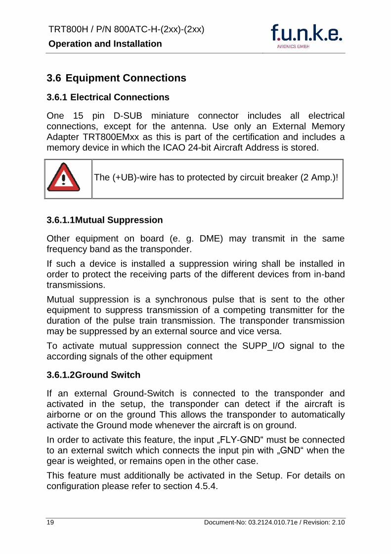
TRT800H PN 800ATC-H-(2xx)-(2xx)
Operation and Installation
20 Document-No 03212401071e Revision 210
3613 Auto-On
The Auto-On input allows to define how the transponder will behave when power is supplied to it
If the aircraft is equipped with a dedicated avionics master switch that switches the power supply to the transponder the pin Auto-On must be wired together with the UB+ pin to the avionic master switch The onoff button on the transponder is without function in that case The transponder will start automatically whenever power is supplied
On aircraft without such an avionics master switch the pin Auto-On must be left unconnected In this case the transponder must be switched on and off via the transponders onoff button on the front panel
362 Static Air Port
Install a silicon soft tube fitting the 5 mm static air hose at the backside of the transponder and secure plumbing with appropriate clamps
37 Wiring
371 Conductor Cross Section
Power Supply (Power GND) AWG20 (062 mmsup2)
Signals AWG22 (038 mmsup2)
The conductors must be approved for aircraft use
TRT800H PN 800ATC-H-(2xx)-(2xx)
Operation and Installation
21 Document-No 03212401071e Revision 210
372 Pin Assignment
The transponder may only be operated together with an external memory address adaptor TRT800EMxx
Pin Signal Remarks Adaptor
Typ(4)
TRT800
EM
Adaptor
Typ(4)
TRT800
EMSS
Adaptor Typ
TRT800
EMRS
1 GND -
2 Remote control(1) Input
3 EEPROM Signal TRT800EMxx internal
4 EEPROM Signal TRT800EMxx internal
5 TX RS-232 Serial Output
6 Switched +UB(1) Output
7 Remote control(1) Output
8 +UB power supply Input
9 GND -
10 EEPROM VCC TRT800EMxx internal
11 EEPROM GND TRT800EMxx internal
12 RX RS-232 Serial Input
13 Suppression Input Output
14 Auto-On(2) Input(2)
15 Fly-GND Switch(3) Input(3)
= in the plug and get out = in the plug and not get out ∕ = internal connection to the device
(1) SWITCHED +UB OUT Interface Remote control
May only be used for compatible funke AVIONICS devices Do not connect pins if interface is not used
(2) Auto-On Connect to +UB override front panel onoff button Leave unconnected to use front panel onoff button
(3) Ground Switch
FLY-GND
If an external Ground Switch is connected it must connect this pin to GND to indicate the on-ground condition Leave open otherwise
(4) Adaptors TRT800EM amp TRT800EMSS
Adaptor version does not provide full interface capability (see table for details)
TRT800H PN 800ATC-H-(2xx)-(2xx)
Operation and Installation
22 Document-No 03212401071e Revision 210
373 Cable plan External Memory EM800
3731 Cable plan TRT800EMRS (older version with interface remote)
to SN 90932013
DSUB 15pol
TRT800HTRT800A
lt PIN-5 gt
lt PIN-12gt
lt PIN-15gt
lt PIN-13gt
lt PIN-7 gt
lt PIN-2 gt
lt PIN-6 gt
lt PIN-1 gt
lt PIN-9 gt
lt PIN-8 gt
lt PIN-14gt
TXD
RXD
FLY_GND
SUPP_IO
GND
open
cable
ends
Remote Binder
Connector
female
white
black
yellow
red
shield
blue
red
brown
GND
+UB
AUTO-ON(2)(3)
black
white
red
yellow
shield
Binder Connector female
(solder side)
1 2 3 4 5 6 7 8
9 10 11 12 13 14 15
D-SUB Connector female
(solder side)
open
cable
ends
1 New interface available
-at TRT800H starting from SN 30430109 with SW V53
-at TRT800A starting with SW V53 2 New TRT800H interface starting from HW 60 3 port function not available at TRT800A
3
4 2
5 1
RMT-LIGHT
GND
RMT-TXD
RMT-SW+UB
RMT-RXD
RMT-TXD(1)
RMT-RXD(1)
RMT-SW+UB(2)(3)
RMT-LIGHT(2)
GND(1)
TRT800H PN 800ATC-H-(2xx)-(2xx)
Operation and Installation
23 Document-No 03212401071e Revision 210
3732 Cable plan TRT800EMRS (newer version with interface remote)
from SN 90932114
DSUB 15pol
TRT800HTRT800A
lt PIN-5 gt
lt PIN-12gt
lt PIN-15gt
lt PIN-13gt
lt PIN-7 gt
lt PIN-2 gt
lt PIN-6 gt
lt PIN-1 gt
lt PIN-9 gt
lt PIN-8 gt
lt PIN-14gt
TXD
RXD
FLY_GND
SUPP_IO
GND
open
cable
ends
Remote Binder
Connector
female
white
brown
yellow
green
shield
blue
red
brown
GND
+UB
AUTO-ON(2)(3)
brown
white
green
yellow
shield
Binder Connector female
(solder side)
1 2 3 4 5 6 7 8
9 10 11 12 13 14 15
D-SUB Connector female
(solder side)
open
cable
ends
1 New interface available
-at TRT800H starting from SN 30430109 with SW V53
-at TRT800A starting with SW V53 2 New TRT800H interface starting from HW 60 3 port function not available at TRT800A
3
4 2
5 1
RMT-LIGHT
GND
RMT-TXD
RMT-SW+UB
RMT-RXD
RMT-TXD(1)
RMT-RXD(1)
RMT-SW+UB(2)(3)
RMT-LIGHT(2)
GND(1)
TRT800H PN 800ATC-H-(2xx)-(2xx)
Operation and Installation
24 Document-No 03212401071e Revision 210
3733 Cable plan TRT800EMSS (newer version without interface remote)
from SN 91032115
The External ndash Memory ndash Address - Adapter TRT800EMxx contains electronic parts and must not be opened Opening or modifying the connector leads to the loss of airworthiness certification
DSUB 15pol
TRT800HTRT800A
lt PIN-5 gt
lt PIN-12gt
lt PIN-15gt
lt PIN-13gt
lt PIN-1 gt
lt PIN-9 gt
lt PIN-8 gt
lt PIN-14gt
TXD
RXD
FLY_GND
SUPP_IO
GND
open
cable
ends
white
brown
yellow
green
shield
blue
red
brown
GND
+UB
AUTO-ON(2)(3)
open
cable
ends
2 New TRT800H interface starting from HW 60 3 port function not available at TRT800A
1 2 3 4 5 6 7 8
9 10 11 12 13 14 15
D-SUB Connector female
(solder side)
TRT800H PN 800ATC-H-(2xx)-(2xx)
Operation and Installation
25 Document-No 03212401071e Revision 210
38 Antenna
381 Antenna Selection
Recommended antennas see section 311 Accessories
Choose an antenna type compatible with the vehicle and the mounting location
Specified features depend on proper installation of the antenna
The radiation pattern needs to be verified considering aircraft type and mounting location
The electrical interference between the antenna and any other equipment must be taken into account in such a way that no reduction of the performance of any other system will occur
Install only certified antennas
382 Installation Recommendation
Take note of the antenna manufacturerrsquos instructions
The usually deployed Dipole- or Blade antennas necessarily require a high frequency capable solid metal ground plane at the antenna base
For installation in composite aircrafts ground planes are to be added The ground plane should be as large as possible but in any case not smaller than 10 cm x 10 cm If in doubt please contact the aircraft manufacturer
Keep away three feet from any other antenna
Pursue mounting in vertical position under the belly in flight direction
383 Antenna Wiring
Suitable antenna cables see section 311 Accessories
Keep wiring as short as possible
The smallest cable bend radius is 10cm Avoid sharp bends
Keep away from an ADF antenna cable at least 12 inches
Electrical connections to the antenna shall be protected against moisture to avoid loss of efficiency
TRT800H PN 800ATC-H-(2xx)-(2xx)
Operation and Installation
26 Document-No 03212401071e Revision 210
39 Post-Installation Check
All steering and control functions of the aircraft are to be examined in order to exclude disturbances by the wiring
The most important factor in the transponder configuration is the setting of the ICAO address (see section 454)
Attenuation from antenna to transponder at 1090 MHz must not exceed 15 dB
A certified maintenance shop must verify proper operation of the transponder by testing in accordance with Appendix F of ldquo14 CFR Part 43 ndash ATC Transponder Tests and Inspectionsrdquo
TRT800H PN 800ATC-H-(2xx)-(2xx)
Operation and Installation
27 Document-No 03212401071e Revision 210
310 Starting Up
Turn the transponder on with IO After start-up the following screens appear
311 Accessories
Part Number Description
TRKABEL1 Antenna cable 10 m (32 ft) TNC BNC
TRKABEL2 Antenna cable 25 m (82 ft) TNC BNC
TRKABEL3 Antenna cable 40 m (132 ft) TNC BNC
TRKABEL4 Antenna cable 65 m (213 ft) TNC BNC
TRT800EMRS External-Memory (Aircraft-Address-Adaptor) Connection cable with interface TRT-Remote control
CI-105 TransponderDME Antenna TSO C66b C74c
CI105 Comant Industries Inc
Height 325rdquo Weight 90 g (02 lbs)
AV22 Transponder Rod antenna TSO C74c
AV-22 R A Miller Industries
The TRT800H starts in standby mode (indicated with STBY) In order to change into operational mode (indicated with ACS) press MODE If ground switch is connected and status ldquoin flightrdquo is selected TRT800H starts in active mode
Very important is the correct configuration of the 24bit Aircraft-Address (see 454 General Setup)
TRT800H V53
FPGA-Vers 102
2000 FL 030
STBY 7000
TRT800H PN 800ATC-H-(2xx)-(2xx)
Operation and Installation
28 Document-No 03212401071e Revision 210
312 Drawings
3121 Dimensions
20mm15 mm
170 mm
TRT800TRT800H
65 mm
65
mm
Oslash 57 mm
Static Air
Antenna
PowerRS232
3122 Mounting Advices
Connections Area
8
0 m
m
Panel Cut-out
470 mm
470
mm
575 mm
4 x Oslash 4 mm
Oslash
Connector (plug) has to be clamped with both spring locks
No screws may be turned in more than max 15mm into the device ndash even if no hard limit is noticeable
Fixing clips (spring) left right
TRT800H PN 800ATC-H-(2xx)-(2xx)
Operation and Installation
29 Document-No 03212401071e Revision 210
4 TRANSPONDER SETTINGS
41 Overview
The TRT800H is capable of storing the following information
ICAO 24-Bit Aircraft-Address (AA)
Aircraft Category (AC)
Flight Identification (FID)
Ground-Switch (YesNo)
Speed Category (RI)
RS232 Interface Configuration
All of these data are configurable in the Setup and are stored in the external memory module integrated within the housing of the D-Sub connector (included in the delivery)
The cable with this connector shall remain in the aircraft even if the unit is removed to ensure that the ICAO 24bit aircraft address is fixed to the aircraft
Additionally the following usertransponder related settings are stored transponder internally
Active Squawk
Passive Squawk
VFR Squawk
Altitude offset
Display brightness
42 Display Configuration Summary
Transponder provides the opportunity to show summary of complete current settings To access configuration summary pages push and hold
ID in Standby mode Release ID if ldquoSHOW SETUPrdquo is displayed The summary is subdivided into the following pages
TRT800H PN 800ATC-H-(2xx)-(2xx)
Operation and Installation
30 Document-No 03212401071e Revision 210
Page 1
Aircraft Address
Aircraft Category
Flight Identification
MODE
Page 2 Speed Category
Ground Switch option
Remote Header option
MODE
Page 3 RS-232 Settings
Protocol baud rate position (if available)1
MODE
Page 4 Altitude correction settings
(part 1)
MODE
Page 5 Altitude correction settings
(part 2)
Note 1 Position data will only be displayed if
a GPS protocol is set as interface protocol (NMEA FREEFLIGHT AR-NAV)
18000 ft 0ft 25000 ft + 100ft 35000 ft - 50ft
exit
ALTITUDE CORRECTION 2000 ft 0ft 10000 ft + 100ft next
RS-232 NMEA Baud 4800 Pos 481 99 next
Speed Cat 8 Ground Sw YES Remote Hd NO next
AA F E 1 2 3 4 AC 1 9 FID 4 4 E 1 2 3 next
TRT800H PN 800ATC-H-(2xx)-(2xx)
Operation and Installation
31 Document-No 03212401071e Revision 210
GPS receiver is connected and transmits data (if not ldquoPos no datardquo is displayed)
a valid position is transmitted (if not ldquoPos wrong datardquo is displayed)
While configuration summary page is displayed no new position data will be processed
43 General settings
431 ICAO 24-Bit Aircraft Address (AA)
Ask your national aviation authority (e g in Germany LBA Referat B5 Department ldquoVerkehrszulassungrdquo) how to obtain the AA In the case of aerial sports equipment the contact point would be the respective associations Only the assigned AA has to be used and must not be modified at any time because a duplicate address would jeopardize the data surveillance and integrity figures of Mode S
If no AA is stored after power on the display shows ldquoCRADLE OFFrdquo and the transponder operates in Mode AC
(Configuration of the AA see section 454)
432 Aircraft Category (AC)
Code Description Code Description
11 Emergency Vehicle 1C Ultra-Light Paraglider
12 Service Vehicle 1E Drone
19 Glider 21 Aircraft (D-Exxx) lt 15500 lbs Motor Glider (D-Kxxx)
1A Balloon amp Airship 22 Aircraft ge 15500 lbslt 75000 lbs
1B Paratrooper 27 Rotorcraft
Only one of the Codes mentioned in the table above must be used
Setuprarr454
Setuprarr454
TRT800H PN 800ATC-H-(2xx)-(2xx)
Operation and Installation
32 Document-No 03212401071e Revision 210
433 Flight-ID (FID)
Per ICAO regulation Mode-S data must contain a valid flight identification (FID) to ensure that the correlation between flight plan and radar data will work automatically
FID setting is required to correspond to the aircraft identification that has been specified at item 7 of the ICAO flight plan It contains seven characters at a maximum (left-aligned no additional zeros dashes or spacesblanks)
For an aircraft using a company call sign the Flight-ID mostly consists of the ICAO three-letter designator for the aircraft operator followed by an identification code eg KLM511 BAW213 JTR25
If no company call sign is used or no flight plan is filed the default FID to be set consists of the registration marking of the aircraft (eg DEABC) with no dashes spacesblanks or additional zeros even if they are included in the registration marking on the aircraft (tail number) While entering the FID into the transponder the last remaining digits must be filled with blanks
The ICAO Flight Plan only specifies 7 characters for FID funke AVIONICS reserves 8 characters as stated in ED-73B for further expansion of the flight plan
The user shall only program 7 characters for FID
Setuprarr454
TRT800H PN 800ATC-H-(2xx)-(2xx)
Operation and Installation
33 Document-No 03212401071e Revision 210
434 Reply Information - Speed Category (RI)
Besides AA AC and FID another important part of the Mode-S data is the Speed Category of the respective aircraft This speed category shall be configured in the setup and must contain one of the following codes
Code Description
08 No maximum airspeed data available
09 Maximum airspeed le 75 kt
10 75 kt gt maximum airspeed le 150 kt
11 150 kt gt maximum airspeed le 300 kt
12 300 kt gt maximum airspeed le 600 kt
13 600 kt gt maximum airspeed le 1200 kt
14 Maximum airspeed gt 1200 kt
15 Not assigned
44 Optional settings
441 Option Ground-Switch
If a ground switch is connected (and enabled in setup) the transponder is able to determine on-ground and in-flight state On-ground state is activated automatically once the gear touches the ground On-ground state is indicated on display by symbol G (apart from lsquoFrsquo for In-flight-state)
In On-ground-state the transponder will reply differently to certain addressed interrogations Also the transmission rate of some periodically sent data (squitters ADS-B) is reduced This allows ATC to distinguish between airborne aircraft and those on the ground and it reduces the Mode S channel load
For small aircraft authorities normally do not require such a ground switch In this case the transponder will use the same data formats on the ground as in the airborne state
Setuprarr454 Wiringrarr373
Setuprarr454
TRT800H PN 800ATC-H-(2xx)-(2xx)
Operation and Installation
34 Document-No 03212401071e Revision 210
442 Option Remote Header
The transponder provides a TRT800RT remote control interface If a remote header TRT800RT is connected transponder can be remote controlled via this interface Remote interface provides control of all standard user inputs available during standard operational mode For more information see TRT800RT manual Remote control interface de-activation is setup configurable Remote control interface must only be connected to TRT800RT
443 Serial Interface (RS232)
Using serial interface a GPS receiver can be connected to broadcast own position via ADS-B Out position message Position could be received by other appropriately equipped aircrafts and processed for collision avoidance ADS-B Out functionality
The ADS-B function of this device has not been evaluated during the FAA TSO certification process other than to ensure non-interference Due to the SW assurance of DAL D the ADS-B function cannot be used in the US National Airspace Connecting a GPS source will not comply to FAA certification requirements with regard to ADS-B
Supported formatsprotocols are
Option Description Baud rate
FREEFLIGHT GPSWAAS Sensor 1201
NexNav NNL 3101
19200
AR-NAV Bendix King
KLN 89B KLN 94 ldquoStandard RS232 Sentencerdquo
KMD 150 ldquoSentence Type 1rdquo
Garmin 400 Series ldquoSentence Type 1rdquo (with and without altitude data)
9600
NMEA NMEA-Format data format RMC is expected
4800
Setuprarr454 Wiringrarr373
Setuprarr454 Wiringrarr373
TRT800H PN 800ATC-H-(2xx)-(2xx)
Operation and Installation
35 Document-No 03212401071e Revision 210
Option Description Baud rate
FAVISIA Glass Cockpit support
FAVISIA Data format to be processed in FAVISIA avionics suite
-
FAVISIA+GPS Data format to be processed in FAVISIA avionics suite (output) and additional processing of incoming NMEA GPS-Receiver position data to support the ADS-B Out functionality
4800
Other
Comm-AB-support
Data format for special purpose An additional data link processor allows COMM-AB operation and processing of the position information of a flight management system simultaneously
38400
Disabled No communication via RS232 interface -
444 Altitude CorrectionOffset
The TRT800H has an integrated temperature compensated high-precision pressure sensor This sensor is factory-calibrated so that it will yield accurate flight level (uncorrected pressure altitude) within the entire altitude range
However due to differences in calibration of the TRT800H pressure sensor and the altimeter in the cockpit it may become necessary to adjust the TRT800H pressure readings so that the value indicated and transmitted by the TRT800H corresponds to the indication of the primary altimeter seen by the pilot within 125 feet (as specified in ETSO C88aSAE AS 8003)
Setting for all described GPS-systems
1 2 position messages per 2 sec
Setuprarr455
TRT800H PN 800ATC-H-(2xx)-(2xx)
Operation and Installation
36 Document-No 03212401071e Revision 210
The check for correspondence between the primary altimeter and the TRT800H is usually performed every 24 months as part of the aircrafts altimeter checks
Altitude correction is based on setup configurable offset values at five interpolation points ( 2000 8000 18000 25000 and 35000 ft)The offset value itself is limited to a range from -100 to + 100ft at each point (10ft steps)
45 Setup Procedure
Programming of the ICAOA 24-bit Aircraft Address and of the Aircraft Category shall be executed by qualified personnel only
A wrong Aircraft Address or Flight ID may cause serious problems ATC or with ACASTCAS systems
Pilot and owner are responsible for correctly set transponder data
451 Setup Menu Control
In order to access the functions described in the following paragraphs push and hold ID in Standby mode Release ID if desired counter value menu name is displayed to enter the menu The following menu entries are selectable
Count Displayed Name Function
03 FID FID is displayed
48 CHANGE FID Enter FID setup page
913 SHOW SETUP Enter setup summary listed on different pages (no changes possible)
2528 ENTER SETUP Enter transponder general configuration pages
3134 ALTITUDE CORRECTION
Enter altitude correction menu
TRT800H PN 800ATC-H-(2xx)-(2xx)
Operation and Installation
37 Document-No 03212401071e Revision 210
452 Transponder configurationrecord structure
Aircraft related parts of transponder configuration are stored in one out of eight possible records (record=presetting) Each record contains the following information
Aircraft Address (AA 24bit)
Aircraft category (AC)
Flight identification (FID 6-8 numbersletters)
RS-232 Interface setting (eg GPS protocol)
Ground-Switch setting (Installed YesNo)
Speed category (RI) of the respective aircraft
Remote Header setting (Installed YesNo)
User related settings (eg squawk codes display brightness) are stored once in one global record (transponder internally)
453 Transponder configurationrecord handling
At least one record is stored in external memory Up to 8 records can be additional be applied during setup process
If more than one record is applied the active record must be selected out of a list (determined by FID) during start-up of the transponder
Previously applied records can be deleted again by filling FID with zerorsquos only
454 General Setup
Any menu item can be passed by MODE If no changes are made the original settings will remain stored Modification of one menu item does not impact the others No entries will be deleted
TRT800H PN 800ATC-H-(2xx)-(2xx)
Operation and Installation
38 Document-No 03212401071e Revision 210
Step Display (Example)
1 Start-up Transponder
2 Ensure the transponder-mode is bdquoSTBYldquo If necessary change the mode by pressing MODE
3 Press ID A counter is shown at the upper-right corner Hold ID till ldquoENTER SETUPrdquo is displayed
4 After release of ID the first setup menu is displayed
5 helliphellipselect position (^)
rotary knobchange value
MODE
6 With the rotary knob you can select bdquoyesldquo if a Ground Switch is installed if not select ldquonordquo and proceed with step 7
MODE
Record 1
GND Switch YesNo
next
AA EF123456
AC 18
FID ^BCDEFG
next
AA EF123456
AC 18
FID ABCDEFG
next
ENTER SETUP 26
2000 FL 030
STBY 7000
TRT800H PN 800ATC-H-(2xx)-(2xx)
Operation and Installation
39 Document-No 03212401071e Revision 210
Step Display (Example)
7 At this stage the respective speed category shall be selected by using the rotary knob
MODE
8 At this stage a GPS receiver for ADS-B Out can be selected (Selectable by rotary knob)
MODE
9 At this stage remote interface for communication between TRT800H and remote header can be activated (Selectable by rotary knob)
Remote interface must only be activated if a remote header is connected
MODE
10 With ID further Records can now be created and configured as described in the aforementioned steps At start-up of the transponder one of the defined records with all associated configurations need to be selected
MODE
Records ID=Edit Records
EXIT
Record 1
REMOTE Header YesNo
next
Record 1
GPSINTEXT NMEA
next
Record 1
Speed Cat 08-15
next
TRT800H PN 800ATC-H-(2xx)-(2xx)
Operation and Installation
40 Document-No 03212401071e Revision 210
Step Display (Example)
11 You have now left the configuration mode and are back in normal operation
12 Switch off the transponder
13 Switch on the transponder Your ICAO 24-Bit Aircraft Address is now stored
TRT800H V53
FPGA-Vers 102
2000 FL 030
STBY 7000
TRT800H PN 800ATC-H-(2xx)-(2xx)
Operation and Installation
41 Document-No 03212401071e Revision 210
455 Altitude Correction Setup
Altitude correction setup shall be executed by qualified personnel only
Pilot and owner are responsible for correctly set altitude offset values
The usesetting of altitude correction values is only necessary in exceptional cases (see 444 for details)
Altitude correction is based on five interpolation points ( 2000 10000 18000 25000 and 35000 ft)The offset value at each interpolation point can be adjusted in a range from -100 to + 100ft at each point (10ft steps) Offset values set to zero at each interpolation point deactivates altitude correction (defaultfactory setting)
Step Display (Example)
1 Start-up Transponder
2 Ensure the transponder-mode is bdquoSTBYldquo If necessary change the mode by pressing MODE
3 Press ID A counter is shown at the upper-right corner Hold ID till ldquoALTITUDE OFFSETrdquo is displayed
ALTITUDE OFFSET 33
2000 FL 030
STBY 7000
Descriptionrarr444
TRT800H PN 800ATC-H-(2xx)-(2xx)
Operation and Installation
42 Document-No 03212401071e Revision 210
Step Display (Example)
4 After release of ID the first altitude level + corresponding offset value is displayed
5 Change offset value with rotary knob
MODE
6 (9) Repeat last step for another 4 altitude levels 10000ft 18000ft 25000ft 35000ft
MODE
10 You have now left the configuration mode and are back in normal operation
Switch off the transponder
11 Switch on the transponder New altitude offset values will now be used for altitude calculation
Altitude 10000 ft
Offset 0 ft
nextexit
Altitude 2000 ft
Offset 0 ft
next
TRT800H V53
FPGA-Vers 102
2000 FL 030
STBY 7000
Altitude 2000 ft
Offset 0 ft
next
TRT800H PN 800ATC-H-(2xx)-(2xx)
Operation and Installation
43 Document-No 03212401071e Revision 210
5 APPENDIX
51 Technical Data
Compliance CS-ETSO-2C112a
EASA21O269
FAA TSO-C112c
Applicable Documents CS-ETSO-2C112a
FAA TSO-C112c
EUROCAE ED-73C Class 1 Level 2es
RTCA DO-181D Class 1 Level 2es
EUROCAE ED-26
RTCA DO-160D
RTCA DO-178B Software-Level D
Temperature Ranges
Operation -20 degC to +55 degC for 30 min +70degC
Storage -55 degC to +85 degC
Altitude Range le 35 000 ft
Speed Range le 250 kt (TAS)
Shock 6 G Operation
20 G crash safety
Environmental Categories RTCA DO-160D EnvCat [C1Z]CAA[SM]XXXXXXZBAAA[TT]M[B3F3]XXA
Power Supply 138 VDC (10 VDC 16 VDC)
040 A 138 VDC (typ)
070 A 138 VDC (max)
10 W (max)
TRT800H PN 800ATC-H-(2xx)-(2xx)
Operation and Installation
44 Document-No 03212401071e Revision 210
Fuse External 2A-slow-blow fuse
Mounting Panel cut-out d=575 mm
Weight 06 kg (132 lbs)
Receiver Characteristics
Sensitivity
RF input power level resulting in a 90 reply rate
A MTL for ATCRBS and ATCRBSMode S All-Call interrogations -74 dBm plusmn3 dB
B MTL for Mode S interrogations -74 dBm plusmn 3 dB
Reply transmission frequency
1090 plusmn 1 MHz
RF Peak Power Output 21 dBW (126 W) at antenna base (with maximum cable attenuation of 15 dB)
Squitter (ADS-B) transmitted at random intervals uniformly distributed over the range from 08 to 12 seconds full self-verification of data and occurrence
Mode S Elementary Surveillance
ICAO 24-bit Aircraft Address (Hex-Code)
aircraft address as assigned by national aviation authority
FID Flight ID Flight Plan call sign or aircraft registration marking
Capability Report Reports the available data and means by which the transponder can report
Pressure Altitude Up to 35 000 ft in 25 ft increments
Flight Status in-flight on-ground
Mode S Enhanced Surveillance
Level 2es Comm-A Comm-B 56112-Bit-Messages
SI-capability
TRT800H PN 800ATC-H-(2xx)-(2xx)
Operation and Installation
45 Document-No 03212401071e Revision 210
52 Environmental Conditions
Characteristic DOndash160D Section Cat Condition
Temperature Altitude 40
C1
Low ground survival temperature
451 ndash 55degC
Low operating temperature 451 ndash 20degC
High ground survival Temperature
452 + 85degC
High Short-time Operating Temperature
452 + 70degC
High Operating Temperature 453 + 55degC
In-Flight Loss of Cooling 454 Z No auxiliary cooling required
Altitude 461 C1 35 000 ft
Temperature Variation 50 C 2degC change rate minimum per minute
Humidity 60 A
Shock 70 A
6 G operational shocks
20 G Crash Safety
Test Type R in all 6 directions
Vibration 80 S Vibration Curve M
Explosion Proofness 90 X No test required
Water Proofness 100 X No test required
Fluids Susceptibilities 110 X No test required
Sand and Dust 120 X No test required
Fungus Resistance 130 X No test required
Salt Spray 140 X No test required
Magnetic Effect 150 Z Less than 03 m
Power Input (DC) 160 B
Voltage Spike Conducted 170 A
Audio Frequency Conducted Susceptibility
180 A
TRT800H PN 800ATC-H-(2xx)-(2xx)
Operation and Installation
46 Document-No 03212401071e Revision 210
Characteristic DOndash160D Section Cat Condition
Induced Signal Susceptibility 190 A
Radio Frequency Susceptibility
200 TT
Emission of RF Energy 210 M
Lightning Induced Transient Susceptibility
220 B3F3
Lightning Direct Effects 230 X No test required
Icing 240 X No test required
Electrostatic Discharge (ESD) 250 A
53 DO-178B Open Problem Reports
There are no open problem reports for the software of this device
TRT800H PN 800ATC-H-(2xx)-(2xx)
Operation and Installation
47 Document-No 03212401071e Revision 210
Notes
f funke funke means ndash fabrication utilities network know-how engineering
funke AVIONICS GmbH Heinz-Strachowitz-Str 4
DE-86807 Buchloe Germany
phone +49-8241 80066 0
fax +49-8241 80066 99 E-mail
servicefunkeavionicsde wwwfunkeavionicsde
TRT800H PN 800ATC-H-(2xx)-(2xx)
Operation and Installation
21 Document-No 03212401071e Revision 210
372 Pin Assignment
The transponder may only be operated together with an external memory address adaptor TRT800EMxx
Pin Signal Remarks Adaptor
Typ(4)
TRT800
EM
Adaptor
Typ(4)
TRT800
EMSS
Adaptor Typ
TRT800
EMRS
1 GND -
2 Remote control(1) Input
3 EEPROM Signal TRT800EMxx internal
4 EEPROM Signal TRT800EMxx internal
5 TX RS-232 Serial Output
6 Switched +UB(1) Output
7 Remote control(1) Output
8 +UB power supply Input
9 GND -
10 EEPROM VCC TRT800EMxx internal
11 EEPROM GND TRT800EMxx internal
12 RX RS-232 Serial Input
13 Suppression Input Output
14 Auto-On(2) Input(2)
15 Fly-GND Switch(3) Input(3)
= in the plug and get out = in the plug and not get out ∕ = internal connection to the device
(1) SWITCHED +UB OUT Interface Remote control
May only be used for compatible funke AVIONICS devices Do not connect pins if interface is not used
(2) Auto-On Connect to +UB override front panel onoff button Leave unconnected to use front panel onoff button
(3) Ground Switch
FLY-GND
If an external Ground Switch is connected it must connect this pin to GND to indicate the on-ground condition Leave open otherwise
(4) Adaptors TRT800EM amp TRT800EMSS
Adaptor version does not provide full interface capability (see table for details)
TRT800H PN 800ATC-H-(2xx)-(2xx)
Operation and Installation
22 Document-No 03212401071e Revision 210
373 Cable plan External Memory EM800
3731 Cable plan TRT800EMRS (older version with interface remote)
to SN 90932013
DSUB 15pol
TRT800HTRT800A
lt PIN-5 gt
lt PIN-12gt
lt PIN-15gt
lt PIN-13gt
lt PIN-7 gt
lt PIN-2 gt
lt PIN-6 gt
lt PIN-1 gt
lt PIN-9 gt
lt PIN-8 gt
lt PIN-14gt
TXD
RXD
FLY_GND
SUPP_IO
GND
open
cable
ends
Remote Binder
Connector
female
white
black
yellow
red
shield
blue
red
brown
GND
+UB
AUTO-ON(2)(3)
black
white
red
yellow
shield
Binder Connector female
(solder side)
1 2 3 4 5 6 7 8
9 10 11 12 13 14 15
D-SUB Connector female
(solder side)
open
cable
ends
1 New interface available
-at TRT800H starting from SN 30430109 with SW V53
-at TRT800A starting with SW V53 2 New TRT800H interface starting from HW 60 3 port function not available at TRT800A
3
4 2
5 1
RMT-LIGHT
GND
RMT-TXD
RMT-SW+UB
RMT-RXD
RMT-TXD(1)
RMT-RXD(1)
RMT-SW+UB(2)(3)
RMT-LIGHT(2)
GND(1)
TRT800H PN 800ATC-H-(2xx)-(2xx)
Operation and Installation
23 Document-No 03212401071e Revision 210
3732 Cable plan TRT800EMRS (newer version with interface remote)
from SN 90932114
DSUB 15pol
TRT800HTRT800A
lt PIN-5 gt
lt PIN-12gt
lt PIN-15gt
lt PIN-13gt
lt PIN-7 gt
lt PIN-2 gt
lt PIN-6 gt
lt PIN-1 gt
lt PIN-9 gt
lt PIN-8 gt
lt PIN-14gt
TXD
RXD
FLY_GND
SUPP_IO
GND
open
cable
ends
Remote Binder
Connector
female
white
brown
yellow
green
shield
blue
red
brown
GND
+UB
AUTO-ON(2)(3)
brown
white
green
yellow
shield
Binder Connector female
(solder side)
1 2 3 4 5 6 7 8
9 10 11 12 13 14 15
D-SUB Connector female
(solder side)
open
cable
ends
1 New interface available
-at TRT800H starting from SN 30430109 with SW V53
-at TRT800A starting with SW V53 2 New TRT800H interface starting from HW 60 3 port function not available at TRT800A
3
4 2
5 1
RMT-LIGHT
GND
RMT-TXD
RMT-SW+UB
RMT-RXD
RMT-TXD(1)
RMT-RXD(1)
RMT-SW+UB(2)(3)
RMT-LIGHT(2)
GND(1)
TRT800H PN 800ATC-H-(2xx)-(2xx)
Operation and Installation
24 Document-No 03212401071e Revision 210
3733 Cable plan TRT800EMSS (newer version without interface remote)
from SN 91032115
The External ndash Memory ndash Address - Adapter TRT800EMxx contains electronic parts and must not be opened Opening or modifying the connector leads to the loss of airworthiness certification
DSUB 15pol
TRT800HTRT800A
lt PIN-5 gt
lt PIN-12gt
lt PIN-15gt
lt PIN-13gt
lt PIN-1 gt
lt PIN-9 gt
lt PIN-8 gt
lt PIN-14gt
TXD
RXD
FLY_GND
SUPP_IO
GND
open
cable
ends
white
brown
yellow
green
shield
blue
red
brown
GND
+UB
AUTO-ON(2)(3)
open
cable
ends
2 New TRT800H interface starting from HW 60 3 port function not available at TRT800A
1 2 3 4 5 6 7 8
9 10 11 12 13 14 15
D-SUB Connector female
(solder side)
TRT800H PN 800ATC-H-(2xx)-(2xx)
Operation and Installation
25 Document-No 03212401071e Revision 210
38 Antenna
381 Antenna Selection
Recommended antennas see section 311 Accessories
Choose an antenna type compatible with the vehicle and the mounting location
Specified features depend on proper installation of the antenna
The radiation pattern needs to be verified considering aircraft type and mounting location
The electrical interference between the antenna and any other equipment must be taken into account in such a way that no reduction of the performance of any other system will occur
Install only certified antennas
382 Installation Recommendation
Take note of the antenna manufacturerrsquos instructions
The usually deployed Dipole- or Blade antennas necessarily require a high frequency capable solid metal ground plane at the antenna base
For installation in composite aircrafts ground planes are to be added The ground plane should be as large as possible but in any case not smaller than 10 cm x 10 cm If in doubt please contact the aircraft manufacturer
Keep away three feet from any other antenna
Pursue mounting in vertical position under the belly in flight direction
383 Antenna Wiring
Suitable antenna cables see section 311 Accessories
Keep wiring as short as possible
The smallest cable bend radius is 10cm Avoid sharp bends
Keep away from an ADF antenna cable at least 12 inches
Electrical connections to the antenna shall be protected against moisture to avoid loss of efficiency
TRT800H PN 800ATC-H-(2xx)-(2xx)
Operation and Installation
26 Document-No 03212401071e Revision 210
39 Post-Installation Check
All steering and control functions of the aircraft are to be examined in order to exclude disturbances by the wiring
The most important factor in the transponder configuration is the setting of the ICAO address (see section 454)
Attenuation from antenna to transponder at 1090 MHz must not exceed 15 dB
A certified maintenance shop must verify proper operation of the transponder by testing in accordance with Appendix F of ldquo14 CFR Part 43 ndash ATC Transponder Tests and Inspectionsrdquo
TRT800H PN 800ATC-H-(2xx)-(2xx)
Operation and Installation
27 Document-No 03212401071e Revision 210
310 Starting Up
Turn the transponder on with IO After start-up the following screens appear
311 Accessories
Part Number Description
TRKABEL1 Antenna cable 10 m (32 ft) TNC BNC
TRKABEL2 Antenna cable 25 m (82 ft) TNC BNC
TRKABEL3 Antenna cable 40 m (132 ft) TNC BNC
TRKABEL4 Antenna cable 65 m (213 ft) TNC BNC
TRT800EMRS External-Memory (Aircraft-Address-Adaptor) Connection cable with interface TRT-Remote control
CI-105 TransponderDME Antenna TSO C66b C74c
CI105 Comant Industries Inc
Height 325rdquo Weight 90 g (02 lbs)
AV22 Transponder Rod antenna TSO C74c
AV-22 R A Miller Industries
The TRT800H starts in standby mode (indicated with STBY) In order to change into operational mode (indicated with ACS) press MODE If ground switch is connected and status ldquoin flightrdquo is selected TRT800H starts in active mode
Very important is the correct configuration of the 24bit Aircraft-Address (see 454 General Setup)
TRT800H V53
FPGA-Vers 102
2000 FL 030
STBY 7000
TRT800H PN 800ATC-H-(2xx)-(2xx)
Operation and Installation
28 Document-No 03212401071e Revision 210
312 Drawings
3121 Dimensions
20mm15 mm
170 mm
TRT800TRT800H
65 mm
65
mm
Oslash 57 mm
Static Air
Antenna
PowerRS232
3122 Mounting Advices
Connections Area
8
0 m
m
Panel Cut-out
470 mm
470
mm
575 mm
4 x Oslash 4 mm
Oslash
Connector (plug) has to be clamped with both spring locks
No screws may be turned in more than max 15mm into the device ndash even if no hard limit is noticeable
Fixing clips (spring) left right
TRT800H PN 800ATC-H-(2xx)-(2xx)
Operation and Installation
29 Document-No 03212401071e Revision 210
4 TRANSPONDER SETTINGS
41 Overview
The TRT800H is capable of storing the following information
ICAO 24-Bit Aircraft-Address (AA)
Aircraft Category (AC)
Flight Identification (FID)
Ground-Switch (YesNo)
Speed Category (RI)
RS232 Interface Configuration
All of these data are configurable in the Setup and are stored in the external memory module integrated within the housing of the D-Sub connector (included in the delivery)
The cable with this connector shall remain in the aircraft even if the unit is removed to ensure that the ICAO 24bit aircraft address is fixed to the aircraft
Additionally the following usertransponder related settings are stored transponder internally
Active Squawk
Passive Squawk
VFR Squawk
Altitude offset
Display brightness
42 Display Configuration Summary
Transponder provides the opportunity to show summary of complete current settings To access configuration summary pages push and hold
ID in Standby mode Release ID if ldquoSHOW SETUPrdquo is displayed The summary is subdivided into the following pages
TRT800H PN 800ATC-H-(2xx)-(2xx)
Operation and Installation
30 Document-No 03212401071e Revision 210
Page 1
Aircraft Address
Aircraft Category
Flight Identification
MODE
Page 2 Speed Category
Ground Switch option
Remote Header option
MODE
Page 3 RS-232 Settings
Protocol baud rate position (if available)1
MODE
Page 4 Altitude correction settings
(part 1)
MODE
Page 5 Altitude correction settings
(part 2)
Note 1 Position data will only be displayed if
a GPS protocol is set as interface protocol (NMEA FREEFLIGHT AR-NAV)
18000 ft 0ft 25000 ft + 100ft 35000 ft - 50ft
exit
ALTITUDE CORRECTION 2000 ft 0ft 10000 ft + 100ft next
RS-232 NMEA Baud 4800 Pos 481 99 next
Speed Cat 8 Ground Sw YES Remote Hd NO next
AA F E 1 2 3 4 AC 1 9 FID 4 4 E 1 2 3 next
TRT800H PN 800ATC-H-(2xx)-(2xx)
Operation and Installation
31 Document-No 03212401071e Revision 210
GPS receiver is connected and transmits data (if not ldquoPos no datardquo is displayed)
a valid position is transmitted (if not ldquoPos wrong datardquo is displayed)
While configuration summary page is displayed no new position data will be processed
43 General settings
431 ICAO 24-Bit Aircraft Address (AA)
Ask your national aviation authority (e g in Germany LBA Referat B5 Department ldquoVerkehrszulassungrdquo) how to obtain the AA In the case of aerial sports equipment the contact point would be the respective associations Only the assigned AA has to be used and must not be modified at any time because a duplicate address would jeopardize the data surveillance and integrity figures of Mode S
If no AA is stored after power on the display shows ldquoCRADLE OFFrdquo and the transponder operates in Mode AC
(Configuration of the AA see section 454)
432 Aircraft Category (AC)
Code Description Code Description
11 Emergency Vehicle 1C Ultra-Light Paraglider
12 Service Vehicle 1E Drone
19 Glider 21 Aircraft (D-Exxx) lt 15500 lbs Motor Glider (D-Kxxx)
1A Balloon amp Airship 22 Aircraft ge 15500 lbslt 75000 lbs
1B Paratrooper 27 Rotorcraft
Only one of the Codes mentioned in the table above must be used
Setuprarr454
Setuprarr454
TRT800H PN 800ATC-H-(2xx)-(2xx)
Operation and Installation
32 Document-No 03212401071e Revision 210
433 Flight-ID (FID)
Per ICAO regulation Mode-S data must contain a valid flight identification (FID) to ensure that the correlation between flight plan and radar data will work automatically
FID setting is required to correspond to the aircraft identification that has been specified at item 7 of the ICAO flight plan It contains seven characters at a maximum (left-aligned no additional zeros dashes or spacesblanks)
For an aircraft using a company call sign the Flight-ID mostly consists of the ICAO three-letter designator for the aircraft operator followed by an identification code eg KLM511 BAW213 JTR25
If no company call sign is used or no flight plan is filed the default FID to be set consists of the registration marking of the aircraft (eg DEABC) with no dashes spacesblanks or additional zeros even if they are included in the registration marking on the aircraft (tail number) While entering the FID into the transponder the last remaining digits must be filled with blanks
The ICAO Flight Plan only specifies 7 characters for FID funke AVIONICS reserves 8 characters as stated in ED-73B for further expansion of the flight plan
The user shall only program 7 characters for FID
Setuprarr454
TRT800H PN 800ATC-H-(2xx)-(2xx)
Operation and Installation
33 Document-No 03212401071e Revision 210
434 Reply Information - Speed Category (RI)
Besides AA AC and FID another important part of the Mode-S data is the Speed Category of the respective aircraft This speed category shall be configured in the setup and must contain one of the following codes
Code Description
08 No maximum airspeed data available
09 Maximum airspeed le 75 kt
10 75 kt gt maximum airspeed le 150 kt
11 150 kt gt maximum airspeed le 300 kt
12 300 kt gt maximum airspeed le 600 kt
13 600 kt gt maximum airspeed le 1200 kt
14 Maximum airspeed gt 1200 kt
15 Not assigned
44 Optional settings
441 Option Ground-Switch
If a ground switch is connected (and enabled in setup) the transponder is able to determine on-ground and in-flight state On-ground state is activated automatically once the gear touches the ground On-ground state is indicated on display by symbol G (apart from lsquoFrsquo for In-flight-state)
In On-ground-state the transponder will reply differently to certain addressed interrogations Also the transmission rate of some periodically sent data (squitters ADS-B) is reduced This allows ATC to distinguish between airborne aircraft and those on the ground and it reduces the Mode S channel load
For small aircraft authorities normally do not require such a ground switch In this case the transponder will use the same data formats on the ground as in the airborne state
Setuprarr454 Wiringrarr373
Setuprarr454
TRT800H PN 800ATC-H-(2xx)-(2xx)
Operation and Installation
34 Document-No 03212401071e Revision 210
442 Option Remote Header
The transponder provides a TRT800RT remote control interface If a remote header TRT800RT is connected transponder can be remote controlled via this interface Remote interface provides control of all standard user inputs available during standard operational mode For more information see TRT800RT manual Remote control interface de-activation is setup configurable Remote control interface must only be connected to TRT800RT
443 Serial Interface (RS232)
Using serial interface a GPS receiver can be connected to broadcast own position via ADS-B Out position message Position could be received by other appropriately equipped aircrafts and processed for collision avoidance ADS-B Out functionality
The ADS-B function of this device has not been evaluated during the FAA TSO certification process other than to ensure non-interference Due to the SW assurance of DAL D the ADS-B function cannot be used in the US National Airspace Connecting a GPS source will not comply to FAA certification requirements with regard to ADS-B
Supported formatsprotocols are
Option Description Baud rate
FREEFLIGHT GPSWAAS Sensor 1201
NexNav NNL 3101
19200
AR-NAV Bendix King
KLN 89B KLN 94 ldquoStandard RS232 Sentencerdquo
KMD 150 ldquoSentence Type 1rdquo
Garmin 400 Series ldquoSentence Type 1rdquo (with and without altitude data)
9600
NMEA NMEA-Format data format RMC is expected
4800
Setuprarr454 Wiringrarr373
Setuprarr454 Wiringrarr373
TRT800H PN 800ATC-H-(2xx)-(2xx)
Operation and Installation
35 Document-No 03212401071e Revision 210
Option Description Baud rate
FAVISIA Glass Cockpit support
FAVISIA Data format to be processed in FAVISIA avionics suite
-
FAVISIA+GPS Data format to be processed in FAVISIA avionics suite (output) and additional processing of incoming NMEA GPS-Receiver position data to support the ADS-B Out functionality
4800
Other
Comm-AB-support
Data format for special purpose An additional data link processor allows COMM-AB operation and processing of the position information of a flight management system simultaneously
38400
Disabled No communication via RS232 interface -
444 Altitude CorrectionOffset
The TRT800H has an integrated temperature compensated high-precision pressure sensor This sensor is factory-calibrated so that it will yield accurate flight level (uncorrected pressure altitude) within the entire altitude range
However due to differences in calibration of the TRT800H pressure sensor and the altimeter in the cockpit it may become necessary to adjust the TRT800H pressure readings so that the value indicated and transmitted by the TRT800H corresponds to the indication of the primary altimeter seen by the pilot within 125 feet (as specified in ETSO C88aSAE AS 8003)
Setting for all described GPS-systems
1 2 position messages per 2 sec
Setuprarr455
TRT800H PN 800ATC-H-(2xx)-(2xx)
Operation and Installation
36 Document-No 03212401071e Revision 210
The check for correspondence between the primary altimeter and the TRT800H is usually performed every 24 months as part of the aircrafts altimeter checks
Altitude correction is based on setup configurable offset values at five interpolation points ( 2000 8000 18000 25000 and 35000 ft)The offset value itself is limited to a range from -100 to + 100ft at each point (10ft steps)
45 Setup Procedure
Programming of the ICAOA 24-bit Aircraft Address and of the Aircraft Category shall be executed by qualified personnel only
A wrong Aircraft Address or Flight ID may cause serious problems ATC or with ACASTCAS systems
Pilot and owner are responsible for correctly set transponder data
451 Setup Menu Control
In order to access the functions described in the following paragraphs push and hold ID in Standby mode Release ID if desired counter value menu name is displayed to enter the menu The following menu entries are selectable
Count Displayed Name Function
03 FID FID is displayed
48 CHANGE FID Enter FID setup page
913 SHOW SETUP Enter setup summary listed on different pages (no changes possible)
2528 ENTER SETUP Enter transponder general configuration pages
3134 ALTITUDE CORRECTION
Enter altitude correction menu
TRT800H PN 800ATC-H-(2xx)-(2xx)
Operation and Installation
37 Document-No 03212401071e Revision 210
452 Transponder configurationrecord structure
Aircraft related parts of transponder configuration are stored in one out of eight possible records (record=presetting) Each record contains the following information
Aircraft Address (AA 24bit)
Aircraft category (AC)
Flight identification (FID 6-8 numbersletters)
RS-232 Interface setting (eg GPS protocol)
Ground-Switch setting (Installed YesNo)
Speed category (RI) of the respective aircraft
Remote Header setting (Installed YesNo)
User related settings (eg squawk codes display brightness) are stored once in one global record (transponder internally)
453 Transponder configurationrecord handling
At least one record is stored in external memory Up to 8 records can be additional be applied during setup process
If more than one record is applied the active record must be selected out of a list (determined by FID) during start-up of the transponder
Previously applied records can be deleted again by filling FID with zerorsquos only
454 General Setup
Any menu item can be passed by MODE If no changes are made the original settings will remain stored Modification of one menu item does not impact the others No entries will be deleted
TRT800H PN 800ATC-H-(2xx)-(2xx)
Operation and Installation
38 Document-No 03212401071e Revision 210
Step Display (Example)
1 Start-up Transponder
2 Ensure the transponder-mode is bdquoSTBYldquo If necessary change the mode by pressing MODE
3 Press ID A counter is shown at the upper-right corner Hold ID till ldquoENTER SETUPrdquo is displayed
4 After release of ID the first setup menu is displayed
5 helliphellipselect position (^)
rotary knobchange value
MODE
6 With the rotary knob you can select bdquoyesldquo if a Ground Switch is installed if not select ldquonordquo and proceed with step 7
MODE
Record 1
GND Switch YesNo
next
AA EF123456
AC 18
FID ^BCDEFG
next
AA EF123456
AC 18
FID ABCDEFG
next
ENTER SETUP 26
2000 FL 030
STBY 7000
TRT800H PN 800ATC-H-(2xx)-(2xx)
Operation and Installation
39 Document-No 03212401071e Revision 210
Step Display (Example)
7 At this stage the respective speed category shall be selected by using the rotary knob
MODE
8 At this stage a GPS receiver for ADS-B Out can be selected (Selectable by rotary knob)
MODE
9 At this stage remote interface for communication between TRT800H and remote header can be activated (Selectable by rotary knob)
Remote interface must only be activated if a remote header is connected
MODE
10 With ID further Records can now be created and configured as described in the aforementioned steps At start-up of the transponder one of the defined records with all associated configurations need to be selected
MODE
Records ID=Edit Records
EXIT
Record 1
REMOTE Header YesNo
next
Record 1
GPSINTEXT NMEA
next
Record 1
Speed Cat 08-15
next
TRT800H PN 800ATC-H-(2xx)-(2xx)
Operation and Installation
40 Document-No 03212401071e Revision 210
Step Display (Example)
11 You have now left the configuration mode and are back in normal operation
12 Switch off the transponder
13 Switch on the transponder Your ICAO 24-Bit Aircraft Address is now stored
TRT800H V53
FPGA-Vers 102
2000 FL 030
STBY 7000
TRT800H PN 800ATC-H-(2xx)-(2xx)
Operation and Installation
41 Document-No 03212401071e Revision 210
455 Altitude Correction Setup
Altitude correction setup shall be executed by qualified personnel only
Pilot and owner are responsible for correctly set altitude offset values
The usesetting of altitude correction values is only necessary in exceptional cases (see 444 for details)
Altitude correction is based on five interpolation points ( 2000 10000 18000 25000 and 35000 ft)The offset value at each interpolation point can be adjusted in a range from -100 to + 100ft at each point (10ft steps) Offset values set to zero at each interpolation point deactivates altitude correction (defaultfactory setting)
Step Display (Example)
1 Start-up Transponder
2 Ensure the transponder-mode is bdquoSTBYldquo If necessary change the mode by pressing MODE
3 Press ID A counter is shown at the upper-right corner Hold ID till ldquoALTITUDE OFFSETrdquo is displayed
ALTITUDE OFFSET 33
2000 FL 030
STBY 7000
Descriptionrarr444
TRT800H PN 800ATC-H-(2xx)-(2xx)
Operation and Installation
42 Document-No 03212401071e Revision 210
Step Display (Example)
4 After release of ID the first altitude level + corresponding offset value is displayed
5 Change offset value with rotary knob
MODE
6 (9) Repeat last step for another 4 altitude levels 10000ft 18000ft 25000ft 35000ft
MODE
10 You have now left the configuration mode and are back in normal operation
Switch off the transponder
11 Switch on the transponder New altitude offset values will now be used for altitude calculation
Altitude 10000 ft
Offset 0 ft
nextexit
Altitude 2000 ft
Offset 0 ft
next
TRT800H V53
FPGA-Vers 102
2000 FL 030
STBY 7000
Altitude 2000 ft
Offset 0 ft
next
TRT800H PN 800ATC-H-(2xx)-(2xx)
Operation and Installation
43 Document-No 03212401071e Revision 210
5 APPENDIX
51 Technical Data
Compliance CS-ETSO-2C112a
EASA21O269
FAA TSO-C112c
Applicable Documents CS-ETSO-2C112a
FAA TSO-C112c
EUROCAE ED-73C Class 1 Level 2es
RTCA DO-181D Class 1 Level 2es
EUROCAE ED-26
RTCA DO-160D
RTCA DO-178B Software-Level D
Temperature Ranges
Operation -20 degC to +55 degC for 30 min +70degC
Storage -55 degC to +85 degC
Altitude Range le 35 000 ft
Speed Range le 250 kt (TAS)
Shock 6 G Operation
20 G crash safety
Environmental Categories RTCA DO-160D EnvCat [C1Z]CAA[SM]XXXXXXZBAAA[TT]M[B3F3]XXA
Power Supply 138 VDC (10 VDC 16 VDC)
040 A 138 VDC (typ)
070 A 138 VDC (max)
10 W (max)
TRT800H PN 800ATC-H-(2xx)-(2xx)
Operation and Installation
44 Document-No 03212401071e Revision 210
Fuse External 2A-slow-blow fuse
Mounting Panel cut-out d=575 mm
Weight 06 kg (132 lbs)
Receiver Characteristics
Sensitivity
RF input power level resulting in a 90 reply rate
A MTL for ATCRBS and ATCRBSMode S All-Call interrogations -74 dBm plusmn3 dB
B MTL for Mode S interrogations -74 dBm plusmn 3 dB
Reply transmission frequency
1090 plusmn 1 MHz
RF Peak Power Output 21 dBW (126 W) at antenna base (with maximum cable attenuation of 15 dB)
Squitter (ADS-B) transmitted at random intervals uniformly distributed over the range from 08 to 12 seconds full self-verification of data and occurrence
Mode S Elementary Surveillance
ICAO 24-bit Aircraft Address (Hex-Code)
aircraft address as assigned by national aviation authority
FID Flight ID Flight Plan call sign or aircraft registration marking
Capability Report Reports the available data and means by which the transponder can report
Pressure Altitude Up to 35 000 ft in 25 ft increments
Flight Status in-flight on-ground
Mode S Enhanced Surveillance
Level 2es Comm-A Comm-B 56112-Bit-Messages
SI-capability
TRT800H PN 800ATC-H-(2xx)-(2xx)
Operation and Installation
45 Document-No 03212401071e Revision 210
52 Environmental Conditions
Characteristic DOndash160D Section Cat Condition
Temperature Altitude 40
C1
Low ground survival temperature
451 ndash 55degC
Low operating temperature 451 ndash 20degC
High ground survival Temperature
452 + 85degC
High Short-time Operating Temperature
452 + 70degC
High Operating Temperature 453 + 55degC
In-Flight Loss of Cooling 454 Z No auxiliary cooling required
Altitude 461 C1 35 000 ft
Temperature Variation 50 C 2degC change rate minimum per minute
Humidity 60 A
Shock 70 A
6 G operational shocks
20 G Crash Safety
Test Type R in all 6 directions
Vibration 80 S Vibration Curve M
Explosion Proofness 90 X No test required
Water Proofness 100 X No test required
Fluids Susceptibilities 110 X No test required
Sand and Dust 120 X No test required
Fungus Resistance 130 X No test required
Salt Spray 140 X No test required
Magnetic Effect 150 Z Less than 03 m
Power Input (DC) 160 B
Voltage Spike Conducted 170 A
Audio Frequency Conducted Susceptibility
180 A
TRT800H PN 800ATC-H-(2xx)-(2xx)
Operation and Installation
46 Document-No 03212401071e Revision 210
Characteristic DOndash160D Section Cat Condition
Induced Signal Susceptibility 190 A
Radio Frequency Susceptibility
200 TT
Emission of RF Energy 210 M
Lightning Induced Transient Susceptibility
220 B3F3
Lightning Direct Effects 230 X No test required
Icing 240 X No test required
Electrostatic Discharge (ESD) 250 A
53 DO-178B Open Problem Reports
There are no open problem reports for the software of this device
TRT800H PN 800ATC-H-(2xx)-(2xx)
Operation and Installation
47 Document-No 03212401071e Revision 210
Notes
f funke funke means ndash fabrication utilities network know-how engineering
funke AVIONICS GmbH Heinz-Strachowitz-Str 4
DE-86807 Buchloe Germany
phone +49-8241 80066 0
fax +49-8241 80066 99 E-mail
servicefunkeavionicsde wwwfunkeavionicsde
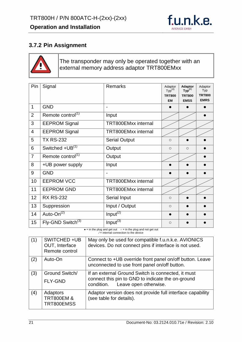
TRT800H PN 800ATC-H-(2xx)-(2xx)
Operation and Installation
22 Document-No 03212401071e Revision 210
373 Cable plan External Memory EM800
3731 Cable plan TRT800EMRS (older version with interface remote)
to SN 90932013
DSUB 15pol
TRT800HTRT800A
lt PIN-5 gt
lt PIN-12gt
lt PIN-15gt
lt PIN-13gt
lt PIN-7 gt
lt PIN-2 gt
lt PIN-6 gt
lt PIN-1 gt
lt PIN-9 gt
lt PIN-8 gt
lt PIN-14gt
TXD
RXD
FLY_GND
SUPP_IO
GND
open
cable
ends
Remote Binder
Connector
female
white
black
yellow
red
shield
blue
red
brown
GND
+UB
AUTO-ON(2)(3)
black
white
red
yellow
shield
Binder Connector female
(solder side)
1 2 3 4 5 6 7 8
9 10 11 12 13 14 15
D-SUB Connector female
(solder side)
open
cable
ends
1 New interface available
-at TRT800H starting from SN 30430109 with SW V53
-at TRT800A starting with SW V53 2 New TRT800H interface starting from HW 60 3 port function not available at TRT800A
3
4 2
5 1
RMT-LIGHT
GND
RMT-TXD
RMT-SW+UB
RMT-RXD
RMT-TXD(1)
RMT-RXD(1)
RMT-SW+UB(2)(3)
RMT-LIGHT(2)
GND(1)
TRT800H PN 800ATC-H-(2xx)-(2xx)
Operation and Installation
23 Document-No 03212401071e Revision 210
3732 Cable plan TRT800EMRS (newer version with interface remote)
from SN 90932114
DSUB 15pol
TRT800HTRT800A
lt PIN-5 gt
lt PIN-12gt
lt PIN-15gt
lt PIN-13gt
lt PIN-7 gt
lt PIN-2 gt
lt PIN-6 gt
lt PIN-1 gt
lt PIN-9 gt
lt PIN-8 gt
lt PIN-14gt
TXD
RXD
FLY_GND
SUPP_IO
GND
open
cable
ends
Remote Binder
Connector
female
white
brown
yellow
green
shield
blue
red
brown
GND
+UB
AUTO-ON(2)(3)
brown
white
green
yellow
shield
Binder Connector female
(solder side)
1 2 3 4 5 6 7 8
9 10 11 12 13 14 15
D-SUB Connector female
(solder side)
open
cable
ends
1 New interface available
-at TRT800H starting from SN 30430109 with SW V53
-at TRT800A starting with SW V53 2 New TRT800H interface starting from HW 60 3 port function not available at TRT800A
3
4 2
5 1
RMT-LIGHT
GND
RMT-TXD
RMT-SW+UB
RMT-RXD
RMT-TXD(1)
RMT-RXD(1)
RMT-SW+UB(2)(3)
RMT-LIGHT(2)
GND(1)
TRT800H PN 800ATC-H-(2xx)-(2xx)
Operation and Installation
24 Document-No 03212401071e Revision 210
3733 Cable plan TRT800EMSS (newer version without interface remote)
from SN 91032115
The External ndash Memory ndash Address - Adapter TRT800EMxx contains electronic parts and must not be opened Opening or modifying the connector leads to the loss of airworthiness certification
DSUB 15pol
TRT800HTRT800A
lt PIN-5 gt
lt PIN-12gt
lt PIN-15gt
lt PIN-13gt
lt PIN-1 gt
lt PIN-9 gt
lt PIN-8 gt
lt PIN-14gt
TXD
RXD
FLY_GND
SUPP_IO
GND
open
cable
ends
white
brown
yellow
green
shield
blue
red
brown
GND
+UB
AUTO-ON(2)(3)
open
cable
ends
2 New TRT800H interface starting from HW 60 3 port function not available at TRT800A
1 2 3 4 5 6 7 8
9 10 11 12 13 14 15
D-SUB Connector female
(solder side)
TRT800H PN 800ATC-H-(2xx)-(2xx)
Operation and Installation
25 Document-No 03212401071e Revision 210
38 Antenna
381 Antenna Selection
Recommended antennas see section 311 Accessories
Choose an antenna type compatible with the vehicle and the mounting location
Specified features depend on proper installation of the antenna
The radiation pattern needs to be verified considering aircraft type and mounting location
The electrical interference between the antenna and any other equipment must be taken into account in such a way that no reduction of the performance of any other system will occur
Install only certified antennas
382 Installation Recommendation
Take note of the antenna manufacturerrsquos instructions
The usually deployed Dipole- or Blade antennas necessarily require a high frequency capable solid metal ground plane at the antenna base
For installation in composite aircrafts ground planes are to be added The ground plane should be as large as possible but in any case not smaller than 10 cm x 10 cm If in doubt please contact the aircraft manufacturer
Keep away three feet from any other antenna
Pursue mounting in vertical position under the belly in flight direction
383 Antenna Wiring
Suitable antenna cables see section 311 Accessories
Keep wiring as short as possible
The smallest cable bend radius is 10cm Avoid sharp bends
Keep away from an ADF antenna cable at least 12 inches
Electrical connections to the antenna shall be protected against moisture to avoid loss of efficiency
TRT800H PN 800ATC-H-(2xx)-(2xx)
Operation and Installation
26 Document-No 03212401071e Revision 210
39 Post-Installation Check
All steering and control functions of the aircraft are to be examined in order to exclude disturbances by the wiring
The most important factor in the transponder configuration is the setting of the ICAO address (see section 454)
Attenuation from antenna to transponder at 1090 MHz must not exceed 15 dB
A certified maintenance shop must verify proper operation of the transponder by testing in accordance with Appendix F of ldquo14 CFR Part 43 ndash ATC Transponder Tests and Inspectionsrdquo
TRT800H PN 800ATC-H-(2xx)-(2xx)
Operation and Installation
27 Document-No 03212401071e Revision 210
310 Starting Up
Turn the transponder on with IO After start-up the following screens appear
311 Accessories
Part Number Description
TRKABEL1 Antenna cable 10 m (32 ft) TNC BNC
TRKABEL2 Antenna cable 25 m (82 ft) TNC BNC
TRKABEL3 Antenna cable 40 m (132 ft) TNC BNC
TRKABEL4 Antenna cable 65 m (213 ft) TNC BNC
TRT800EMRS External-Memory (Aircraft-Address-Adaptor) Connection cable with interface TRT-Remote control
CI-105 TransponderDME Antenna TSO C66b C74c
CI105 Comant Industries Inc
Height 325rdquo Weight 90 g (02 lbs)
AV22 Transponder Rod antenna TSO C74c
AV-22 R A Miller Industries
The TRT800H starts in standby mode (indicated with STBY) In order to change into operational mode (indicated with ACS) press MODE If ground switch is connected and status ldquoin flightrdquo is selected TRT800H starts in active mode
Very important is the correct configuration of the 24bit Aircraft-Address (see 454 General Setup)
TRT800H V53
FPGA-Vers 102
2000 FL 030
STBY 7000
TRT800H PN 800ATC-H-(2xx)-(2xx)
Operation and Installation
28 Document-No 03212401071e Revision 210
312 Drawings
3121 Dimensions
20mm15 mm
170 mm
TRT800TRT800H
65 mm
65
mm
Oslash 57 mm
Static Air
Antenna
PowerRS232
3122 Mounting Advices
Connections Area
8
0 m
m
Panel Cut-out
470 mm
470
mm
575 mm
4 x Oslash 4 mm
Oslash
Connector (plug) has to be clamped with both spring locks
No screws may be turned in more than max 15mm into the device ndash even if no hard limit is noticeable
Fixing clips (spring) left right
TRT800H PN 800ATC-H-(2xx)-(2xx)
Operation and Installation
29 Document-No 03212401071e Revision 210
4 TRANSPONDER SETTINGS
41 Overview
The TRT800H is capable of storing the following information
ICAO 24-Bit Aircraft-Address (AA)
Aircraft Category (AC)
Flight Identification (FID)
Ground-Switch (YesNo)
Speed Category (RI)
RS232 Interface Configuration
All of these data are configurable in the Setup and are stored in the external memory module integrated within the housing of the D-Sub connector (included in the delivery)
The cable with this connector shall remain in the aircraft even if the unit is removed to ensure that the ICAO 24bit aircraft address is fixed to the aircraft
Additionally the following usertransponder related settings are stored transponder internally
Active Squawk
Passive Squawk
VFR Squawk
Altitude offset
Display brightness
42 Display Configuration Summary
Transponder provides the opportunity to show summary of complete current settings To access configuration summary pages push and hold
ID in Standby mode Release ID if ldquoSHOW SETUPrdquo is displayed The summary is subdivided into the following pages
TRT800H PN 800ATC-H-(2xx)-(2xx)
Operation and Installation
30 Document-No 03212401071e Revision 210
Page 1
Aircraft Address
Aircraft Category
Flight Identification
MODE
Page 2 Speed Category
Ground Switch option
Remote Header option
MODE
Page 3 RS-232 Settings
Protocol baud rate position (if available)1
MODE
Page 4 Altitude correction settings
(part 1)
MODE
Page 5 Altitude correction settings
(part 2)
Note 1 Position data will only be displayed if
a GPS protocol is set as interface protocol (NMEA FREEFLIGHT AR-NAV)
18000 ft 0ft 25000 ft + 100ft 35000 ft - 50ft
exit
ALTITUDE CORRECTION 2000 ft 0ft 10000 ft + 100ft next
RS-232 NMEA Baud 4800 Pos 481 99 next
Speed Cat 8 Ground Sw YES Remote Hd NO next
AA F E 1 2 3 4 AC 1 9 FID 4 4 E 1 2 3 next
TRT800H PN 800ATC-H-(2xx)-(2xx)
Operation and Installation
31 Document-No 03212401071e Revision 210
GPS receiver is connected and transmits data (if not ldquoPos no datardquo is displayed)
a valid position is transmitted (if not ldquoPos wrong datardquo is displayed)
While configuration summary page is displayed no new position data will be processed
43 General settings
431 ICAO 24-Bit Aircraft Address (AA)
Ask your national aviation authority (e g in Germany LBA Referat B5 Department ldquoVerkehrszulassungrdquo) how to obtain the AA In the case of aerial sports equipment the contact point would be the respective associations Only the assigned AA has to be used and must not be modified at any time because a duplicate address would jeopardize the data surveillance and integrity figures of Mode S
If no AA is stored after power on the display shows ldquoCRADLE OFFrdquo and the transponder operates in Mode AC
(Configuration of the AA see section 454)
432 Aircraft Category (AC)
Code Description Code Description
11 Emergency Vehicle 1C Ultra-Light Paraglider
12 Service Vehicle 1E Drone
19 Glider 21 Aircraft (D-Exxx) lt 15500 lbs Motor Glider (D-Kxxx)
1A Balloon amp Airship 22 Aircraft ge 15500 lbslt 75000 lbs
1B Paratrooper 27 Rotorcraft
Only one of the Codes mentioned in the table above must be used
Setuprarr454
Setuprarr454
TRT800H PN 800ATC-H-(2xx)-(2xx)
Operation and Installation
32 Document-No 03212401071e Revision 210
433 Flight-ID (FID)
Per ICAO regulation Mode-S data must contain a valid flight identification (FID) to ensure that the correlation between flight plan and radar data will work automatically
FID setting is required to correspond to the aircraft identification that has been specified at item 7 of the ICAO flight plan It contains seven characters at a maximum (left-aligned no additional zeros dashes or spacesblanks)
For an aircraft using a company call sign the Flight-ID mostly consists of the ICAO three-letter designator for the aircraft operator followed by an identification code eg KLM511 BAW213 JTR25
If no company call sign is used or no flight plan is filed the default FID to be set consists of the registration marking of the aircraft (eg DEABC) with no dashes spacesblanks or additional zeros even if they are included in the registration marking on the aircraft (tail number) While entering the FID into the transponder the last remaining digits must be filled with blanks
The ICAO Flight Plan only specifies 7 characters for FID funke AVIONICS reserves 8 characters as stated in ED-73B for further expansion of the flight plan
The user shall only program 7 characters for FID
Setuprarr454
TRT800H PN 800ATC-H-(2xx)-(2xx)
Operation and Installation
33 Document-No 03212401071e Revision 210
434 Reply Information - Speed Category (RI)
Besides AA AC and FID another important part of the Mode-S data is the Speed Category of the respective aircraft This speed category shall be configured in the setup and must contain one of the following codes
Code Description
08 No maximum airspeed data available
09 Maximum airspeed le 75 kt
10 75 kt gt maximum airspeed le 150 kt
11 150 kt gt maximum airspeed le 300 kt
12 300 kt gt maximum airspeed le 600 kt
13 600 kt gt maximum airspeed le 1200 kt
14 Maximum airspeed gt 1200 kt
15 Not assigned
44 Optional settings
441 Option Ground-Switch
If a ground switch is connected (and enabled in setup) the transponder is able to determine on-ground and in-flight state On-ground state is activated automatically once the gear touches the ground On-ground state is indicated on display by symbol G (apart from lsquoFrsquo for In-flight-state)
In On-ground-state the transponder will reply differently to certain addressed interrogations Also the transmission rate of some periodically sent data (squitters ADS-B) is reduced This allows ATC to distinguish between airborne aircraft and those on the ground and it reduces the Mode S channel load
For small aircraft authorities normally do not require such a ground switch In this case the transponder will use the same data formats on the ground as in the airborne state
Setuprarr454 Wiringrarr373
Setuprarr454
TRT800H PN 800ATC-H-(2xx)-(2xx)
Operation and Installation
34 Document-No 03212401071e Revision 210
442 Option Remote Header
The transponder provides a TRT800RT remote control interface If a remote header TRT800RT is connected transponder can be remote controlled via this interface Remote interface provides control of all standard user inputs available during standard operational mode For more information see TRT800RT manual Remote control interface de-activation is setup configurable Remote control interface must only be connected to TRT800RT
443 Serial Interface (RS232)
Using serial interface a GPS receiver can be connected to broadcast own position via ADS-B Out position message Position could be received by other appropriately equipped aircrafts and processed for collision avoidance ADS-B Out functionality
The ADS-B function of this device has not been evaluated during the FAA TSO certification process other than to ensure non-interference Due to the SW assurance of DAL D the ADS-B function cannot be used in the US National Airspace Connecting a GPS source will not comply to FAA certification requirements with regard to ADS-B
Supported formatsprotocols are
Option Description Baud rate
FREEFLIGHT GPSWAAS Sensor 1201
NexNav NNL 3101
19200
AR-NAV Bendix King
KLN 89B KLN 94 ldquoStandard RS232 Sentencerdquo
KMD 150 ldquoSentence Type 1rdquo
Garmin 400 Series ldquoSentence Type 1rdquo (with and without altitude data)
9600
NMEA NMEA-Format data format RMC is expected
4800
Setuprarr454 Wiringrarr373
Setuprarr454 Wiringrarr373
TRT800H PN 800ATC-H-(2xx)-(2xx)
Operation and Installation
35 Document-No 03212401071e Revision 210
Option Description Baud rate
FAVISIA Glass Cockpit support
FAVISIA Data format to be processed in FAVISIA avionics suite
-
FAVISIA+GPS Data format to be processed in FAVISIA avionics suite (output) and additional processing of incoming NMEA GPS-Receiver position data to support the ADS-B Out functionality
4800
Other
Comm-AB-support
Data format for special purpose An additional data link processor allows COMM-AB operation and processing of the position information of a flight management system simultaneously
38400
Disabled No communication via RS232 interface -
444 Altitude CorrectionOffset
The TRT800H has an integrated temperature compensated high-precision pressure sensor This sensor is factory-calibrated so that it will yield accurate flight level (uncorrected pressure altitude) within the entire altitude range
However due to differences in calibration of the TRT800H pressure sensor and the altimeter in the cockpit it may become necessary to adjust the TRT800H pressure readings so that the value indicated and transmitted by the TRT800H corresponds to the indication of the primary altimeter seen by the pilot within 125 feet (as specified in ETSO C88aSAE AS 8003)
Setting for all described GPS-systems
1 2 position messages per 2 sec
Setuprarr455
TRT800H PN 800ATC-H-(2xx)-(2xx)
Operation and Installation
36 Document-No 03212401071e Revision 210
The check for correspondence between the primary altimeter and the TRT800H is usually performed every 24 months as part of the aircrafts altimeter checks
Altitude correction is based on setup configurable offset values at five interpolation points ( 2000 8000 18000 25000 and 35000 ft)The offset value itself is limited to a range from -100 to + 100ft at each point (10ft steps)
45 Setup Procedure
Programming of the ICAOA 24-bit Aircraft Address and of the Aircraft Category shall be executed by qualified personnel only
A wrong Aircraft Address or Flight ID may cause serious problems ATC or with ACASTCAS systems
Pilot and owner are responsible for correctly set transponder data
451 Setup Menu Control
In order to access the functions described in the following paragraphs push and hold ID in Standby mode Release ID if desired counter value menu name is displayed to enter the menu The following menu entries are selectable
Count Displayed Name Function
03 FID FID is displayed
48 CHANGE FID Enter FID setup page
913 SHOW SETUP Enter setup summary listed on different pages (no changes possible)
2528 ENTER SETUP Enter transponder general configuration pages
3134 ALTITUDE CORRECTION
Enter altitude correction menu
TRT800H PN 800ATC-H-(2xx)-(2xx)
Operation and Installation
37 Document-No 03212401071e Revision 210
452 Transponder configurationrecord structure
Aircraft related parts of transponder configuration are stored in one out of eight possible records (record=presetting) Each record contains the following information
Aircraft Address (AA 24bit)
Aircraft category (AC)
Flight identification (FID 6-8 numbersletters)
RS-232 Interface setting (eg GPS protocol)
Ground-Switch setting (Installed YesNo)
Speed category (RI) of the respective aircraft
Remote Header setting (Installed YesNo)
User related settings (eg squawk codes display brightness) are stored once in one global record (transponder internally)
453 Transponder configurationrecord handling
At least one record is stored in external memory Up to 8 records can be additional be applied during setup process
If more than one record is applied the active record must be selected out of a list (determined by FID) during start-up of the transponder
Previously applied records can be deleted again by filling FID with zerorsquos only
454 General Setup
Any menu item can be passed by MODE If no changes are made the original settings will remain stored Modification of one menu item does not impact the others No entries will be deleted
TRT800H PN 800ATC-H-(2xx)-(2xx)
Operation and Installation
38 Document-No 03212401071e Revision 210
Step Display (Example)
1 Start-up Transponder
2 Ensure the transponder-mode is bdquoSTBYldquo If necessary change the mode by pressing MODE
3 Press ID A counter is shown at the upper-right corner Hold ID till ldquoENTER SETUPrdquo is displayed
4 After release of ID the first setup menu is displayed
5 helliphellipselect position (^)
rotary knobchange value
MODE
6 With the rotary knob you can select bdquoyesldquo if a Ground Switch is installed if not select ldquonordquo and proceed with step 7
MODE
Record 1
GND Switch YesNo
next
AA EF123456
AC 18
FID ^BCDEFG
next
AA EF123456
AC 18
FID ABCDEFG
next
ENTER SETUP 26
2000 FL 030
STBY 7000
TRT800H PN 800ATC-H-(2xx)-(2xx)
Operation and Installation
39 Document-No 03212401071e Revision 210
Step Display (Example)
7 At this stage the respective speed category shall be selected by using the rotary knob
MODE
8 At this stage a GPS receiver for ADS-B Out can be selected (Selectable by rotary knob)
MODE
9 At this stage remote interface for communication between TRT800H and remote header can be activated (Selectable by rotary knob)
Remote interface must only be activated if a remote header is connected
MODE
10 With ID further Records can now be created and configured as described in the aforementioned steps At start-up of the transponder one of the defined records with all associated configurations need to be selected
MODE
Records ID=Edit Records
EXIT
Record 1
REMOTE Header YesNo
next
Record 1
GPSINTEXT NMEA
next
Record 1
Speed Cat 08-15
next
TRT800H PN 800ATC-H-(2xx)-(2xx)
Operation and Installation
40 Document-No 03212401071e Revision 210
Step Display (Example)
11 You have now left the configuration mode and are back in normal operation
12 Switch off the transponder
13 Switch on the transponder Your ICAO 24-Bit Aircraft Address is now stored
TRT800H V53
FPGA-Vers 102
2000 FL 030
STBY 7000
TRT800H PN 800ATC-H-(2xx)-(2xx)
Operation and Installation
41 Document-No 03212401071e Revision 210
455 Altitude Correction Setup
Altitude correction setup shall be executed by qualified personnel only
Pilot and owner are responsible for correctly set altitude offset values
The usesetting of altitude correction values is only necessary in exceptional cases (see 444 for details)
Altitude correction is based on five interpolation points ( 2000 10000 18000 25000 and 35000 ft)The offset value at each interpolation point can be adjusted in a range from -100 to + 100ft at each point (10ft steps) Offset values set to zero at each interpolation point deactivates altitude correction (defaultfactory setting)
Step Display (Example)
1 Start-up Transponder
2 Ensure the transponder-mode is bdquoSTBYldquo If necessary change the mode by pressing MODE
3 Press ID A counter is shown at the upper-right corner Hold ID till ldquoALTITUDE OFFSETrdquo is displayed
ALTITUDE OFFSET 33
2000 FL 030
STBY 7000
Descriptionrarr444
TRT800H PN 800ATC-H-(2xx)-(2xx)
Operation and Installation
42 Document-No 03212401071e Revision 210
Step Display (Example)
4 After release of ID the first altitude level + corresponding offset value is displayed
5 Change offset value with rotary knob
MODE
6 (9) Repeat last step for another 4 altitude levels 10000ft 18000ft 25000ft 35000ft
MODE
10 You have now left the configuration mode and are back in normal operation
Switch off the transponder
11 Switch on the transponder New altitude offset values will now be used for altitude calculation
Altitude 10000 ft
Offset 0 ft
nextexit
Altitude 2000 ft
Offset 0 ft
next
TRT800H V53
FPGA-Vers 102
2000 FL 030
STBY 7000
Altitude 2000 ft
Offset 0 ft
next
TRT800H PN 800ATC-H-(2xx)-(2xx)
Operation and Installation
43 Document-No 03212401071e Revision 210
5 APPENDIX
51 Technical Data
Compliance CS-ETSO-2C112a
EASA21O269
FAA TSO-C112c
Applicable Documents CS-ETSO-2C112a
FAA TSO-C112c
EUROCAE ED-73C Class 1 Level 2es
RTCA DO-181D Class 1 Level 2es
EUROCAE ED-26
RTCA DO-160D
RTCA DO-178B Software-Level D
Temperature Ranges
Operation -20 degC to +55 degC for 30 min +70degC
Storage -55 degC to +85 degC
Altitude Range le 35 000 ft
Speed Range le 250 kt (TAS)
Shock 6 G Operation
20 G crash safety
Environmental Categories RTCA DO-160D EnvCat [C1Z]CAA[SM]XXXXXXZBAAA[TT]M[B3F3]XXA
Power Supply 138 VDC (10 VDC 16 VDC)
040 A 138 VDC (typ)
070 A 138 VDC (max)
10 W (max)
TRT800H PN 800ATC-H-(2xx)-(2xx)
Operation and Installation
44 Document-No 03212401071e Revision 210
Fuse External 2A-slow-blow fuse
Mounting Panel cut-out d=575 mm
Weight 06 kg (132 lbs)
Receiver Characteristics
Sensitivity
RF input power level resulting in a 90 reply rate
A MTL for ATCRBS and ATCRBSMode S All-Call interrogations -74 dBm plusmn3 dB
B MTL for Mode S interrogations -74 dBm plusmn 3 dB
Reply transmission frequency
1090 plusmn 1 MHz
RF Peak Power Output 21 dBW (126 W) at antenna base (with maximum cable attenuation of 15 dB)
Squitter (ADS-B) transmitted at random intervals uniformly distributed over the range from 08 to 12 seconds full self-verification of data and occurrence
Mode S Elementary Surveillance
ICAO 24-bit Aircraft Address (Hex-Code)
aircraft address as assigned by national aviation authority
FID Flight ID Flight Plan call sign or aircraft registration marking
Capability Report Reports the available data and means by which the transponder can report
Pressure Altitude Up to 35 000 ft in 25 ft increments
Flight Status in-flight on-ground
Mode S Enhanced Surveillance
Level 2es Comm-A Comm-B 56112-Bit-Messages
SI-capability
TRT800H PN 800ATC-H-(2xx)-(2xx)
Operation and Installation
45 Document-No 03212401071e Revision 210
52 Environmental Conditions
Characteristic DOndash160D Section Cat Condition
Temperature Altitude 40
C1
Low ground survival temperature
451 ndash 55degC
Low operating temperature 451 ndash 20degC
High ground survival Temperature
452 + 85degC
High Short-time Operating Temperature
452 + 70degC
High Operating Temperature 453 + 55degC
In-Flight Loss of Cooling 454 Z No auxiliary cooling required
Altitude 461 C1 35 000 ft
Temperature Variation 50 C 2degC change rate minimum per minute
Humidity 60 A
Shock 70 A
6 G operational shocks
20 G Crash Safety
Test Type R in all 6 directions
Vibration 80 S Vibration Curve M
Explosion Proofness 90 X No test required
Water Proofness 100 X No test required
Fluids Susceptibilities 110 X No test required
Sand and Dust 120 X No test required
Fungus Resistance 130 X No test required
Salt Spray 140 X No test required
Magnetic Effect 150 Z Less than 03 m
Power Input (DC) 160 B
Voltage Spike Conducted 170 A
Audio Frequency Conducted Susceptibility
180 A
TRT800H PN 800ATC-H-(2xx)-(2xx)
Operation and Installation
46 Document-No 03212401071e Revision 210
Characteristic DOndash160D Section Cat Condition
Induced Signal Susceptibility 190 A
Radio Frequency Susceptibility
200 TT
Emission of RF Energy 210 M
Lightning Induced Transient Susceptibility
220 B3F3
Lightning Direct Effects 230 X No test required
Icing 240 X No test required
Electrostatic Discharge (ESD) 250 A
53 DO-178B Open Problem Reports
There are no open problem reports for the software of this device
TRT800H PN 800ATC-H-(2xx)-(2xx)
Operation and Installation
47 Document-No 03212401071e Revision 210
Notes
f funke funke means ndash fabrication utilities network know-how engineering
funke AVIONICS GmbH Heinz-Strachowitz-Str 4
DE-86807 Buchloe Germany
phone +49-8241 80066 0
fax +49-8241 80066 99 E-mail
servicefunkeavionicsde wwwfunkeavionicsde
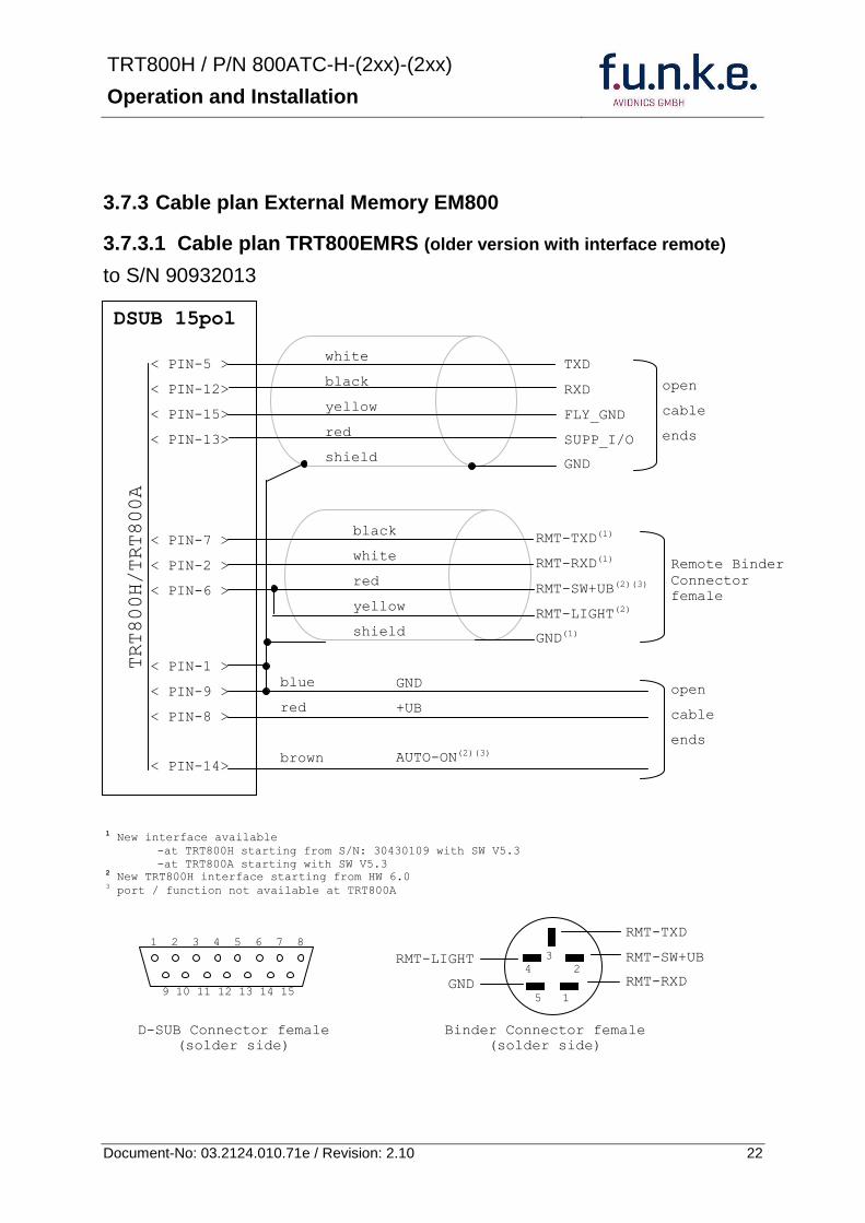
TRT800H PN 800ATC-H-(2xx)-(2xx)
Operation and Installation
23 Document-No 03212401071e Revision 210
3732 Cable plan TRT800EMRS (newer version with interface remote)
from SN 90932114
DSUB 15pol
TRT800HTRT800A
lt PIN-5 gt
lt PIN-12gt
lt PIN-15gt
lt PIN-13gt
lt PIN-7 gt
lt PIN-2 gt
lt PIN-6 gt
lt PIN-1 gt
lt PIN-9 gt
lt PIN-8 gt
lt PIN-14gt
TXD
RXD
FLY_GND
SUPP_IO
GND
open
cable
ends
Remote Binder
Connector
female
white
brown
yellow
green
shield
blue
red
brown
GND
+UB
AUTO-ON(2)(3)
brown
white
green
yellow
shield
Binder Connector female
(solder side)
1 2 3 4 5 6 7 8
9 10 11 12 13 14 15
D-SUB Connector female
(solder side)
open
cable
ends
1 New interface available
-at TRT800H starting from SN 30430109 with SW V53
-at TRT800A starting with SW V53 2 New TRT800H interface starting from HW 60 3 port function not available at TRT800A
3
4 2
5 1
RMT-LIGHT
GND
RMT-TXD
RMT-SW+UB
RMT-RXD
RMT-TXD(1)
RMT-RXD(1)
RMT-SW+UB(2)(3)
RMT-LIGHT(2)
GND(1)
TRT800H PN 800ATC-H-(2xx)-(2xx)
Operation and Installation
24 Document-No 03212401071e Revision 210
3733 Cable plan TRT800EMSS (newer version without interface remote)
from SN 91032115
The External ndash Memory ndash Address - Adapter TRT800EMxx contains electronic parts and must not be opened Opening or modifying the connector leads to the loss of airworthiness certification
DSUB 15pol
TRT800HTRT800A
lt PIN-5 gt
lt PIN-12gt
lt PIN-15gt
lt PIN-13gt
lt PIN-1 gt
lt PIN-9 gt
lt PIN-8 gt
lt PIN-14gt
TXD
RXD
FLY_GND
SUPP_IO
GND
open
cable
ends
white
brown
yellow
green
shield
blue
red
brown
GND
+UB
AUTO-ON(2)(3)
open
cable
ends
2 New TRT800H interface starting from HW 60 3 port function not available at TRT800A
1 2 3 4 5 6 7 8
9 10 11 12 13 14 15
D-SUB Connector female
(solder side)
TRT800H PN 800ATC-H-(2xx)-(2xx)
Operation and Installation
25 Document-No 03212401071e Revision 210
38 Antenna
381 Antenna Selection
Recommended antennas see section 311 Accessories
Choose an antenna type compatible with the vehicle and the mounting location
Specified features depend on proper installation of the antenna
The radiation pattern needs to be verified considering aircraft type and mounting location
The electrical interference between the antenna and any other equipment must be taken into account in such a way that no reduction of the performance of any other system will occur
Install only certified antennas
382 Installation Recommendation
Take note of the antenna manufacturerrsquos instructions
The usually deployed Dipole- or Blade antennas necessarily require a high frequency capable solid metal ground plane at the antenna base
For installation in composite aircrafts ground planes are to be added The ground plane should be as large as possible but in any case not smaller than 10 cm x 10 cm If in doubt please contact the aircraft manufacturer
Keep away three feet from any other antenna
Pursue mounting in vertical position under the belly in flight direction
383 Antenna Wiring
Suitable antenna cables see section 311 Accessories
Keep wiring as short as possible
The smallest cable bend radius is 10cm Avoid sharp bends
Keep away from an ADF antenna cable at least 12 inches
Electrical connections to the antenna shall be protected against moisture to avoid loss of efficiency
TRT800H PN 800ATC-H-(2xx)-(2xx)
Operation and Installation
26 Document-No 03212401071e Revision 210
39 Post-Installation Check
All steering and control functions of the aircraft are to be examined in order to exclude disturbances by the wiring
The most important factor in the transponder configuration is the setting of the ICAO address (see section 454)
Attenuation from antenna to transponder at 1090 MHz must not exceed 15 dB
A certified maintenance shop must verify proper operation of the transponder by testing in accordance with Appendix F of ldquo14 CFR Part 43 ndash ATC Transponder Tests and Inspectionsrdquo
TRT800H PN 800ATC-H-(2xx)-(2xx)
Operation and Installation
27 Document-No 03212401071e Revision 210
310 Starting Up
Turn the transponder on with IO After start-up the following screens appear
311 Accessories
Part Number Description
TRKABEL1 Antenna cable 10 m (32 ft) TNC BNC
TRKABEL2 Antenna cable 25 m (82 ft) TNC BNC
TRKABEL3 Antenna cable 40 m (132 ft) TNC BNC
TRKABEL4 Antenna cable 65 m (213 ft) TNC BNC
TRT800EMRS External-Memory (Aircraft-Address-Adaptor) Connection cable with interface TRT-Remote control
CI-105 TransponderDME Antenna TSO C66b C74c
CI105 Comant Industries Inc
Height 325rdquo Weight 90 g (02 lbs)
AV22 Transponder Rod antenna TSO C74c
AV-22 R A Miller Industries
The TRT800H starts in standby mode (indicated with STBY) In order to change into operational mode (indicated with ACS) press MODE If ground switch is connected and status ldquoin flightrdquo is selected TRT800H starts in active mode
Very important is the correct configuration of the 24bit Aircraft-Address (see 454 General Setup)
TRT800H V53
FPGA-Vers 102
2000 FL 030
STBY 7000
TRT800H PN 800ATC-H-(2xx)-(2xx)
Operation and Installation
28 Document-No 03212401071e Revision 210
312 Drawings
3121 Dimensions
20mm15 mm
170 mm
TRT800TRT800H
65 mm
65
mm
Oslash 57 mm
Static Air
Antenna
PowerRS232
3122 Mounting Advices
Connections Area
8
0 m
m
Panel Cut-out
470 mm
470
mm
575 mm
4 x Oslash 4 mm
Oslash
Connector (plug) has to be clamped with both spring locks
No screws may be turned in more than max 15mm into the device ndash even if no hard limit is noticeable
Fixing clips (spring) left right
TRT800H PN 800ATC-H-(2xx)-(2xx)
Operation and Installation
29 Document-No 03212401071e Revision 210
4 TRANSPONDER SETTINGS
41 Overview
The TRT800H is capable of storing the following information
ICAO 24-Bit Aircraft-Address (AA)
Aircraft Category (AC)
Flight Identification (FID)
Ground-Switch (YesNo)
Speed Category (RI)
RS232 Interface Configuration
All of these data are configurable in the Setup and are stored in the external memory module integrated within the housing of the D-Sub connector (included in the delivery)
The cable with this connector shall remain in the aircraft even if the unit is removed to ensure that the ICAO 24bit aircraft address is fixed to the aircraft
Additionally the following usertransponder related settings are stored transponder internally
Active Squawk
Passive Squawk
VFR Squawk
Altitude offset
Display brightness
42 Display Configuration Summary
Transponder provides the opportunity to show summary of complete current settings To access configuration summary pages push and hold
ID in Standby mode Release ID if ldquoSHOW SETUPrdquo is displayed The summary is subdivided into the following pages
TRT800H PN 800ATC-H-(2xx)-(2xx)
Operation and Installation
30 Document-No 03212401071e Revision 210
Page 1
Aircraft Address
Aircraft Category
Flight Identification
MODE
Page 2 Speed Category
Ground Switch option
Remote Header option
MODE
Page 3 RS-232 Settings
Protocol baud rate position (if available)1
MODE
Page 4 Altitude correction settings
(part 1)
MODE
Page 5 Altitude correction settings
(part 2)
Note 1 Position data will only be displayed if
a GPS protocol is set as interface protocol (NMEA FREEFLIGHT AR-NAV)
18000 ft 0ft 25000 ft + 100ft 35000 ft - 50ft
exit
ALTITUDE CORRECTION 2000 ft 0ft 10000 ft + 100ft next
RS-232 NMEA Baud 4800 Pos 481 99 next
Speed Cat 8 Ground Sw YES Remote Hd NO next
AA F E 1 2 3 4 AC 1 9 FID 4 4 E 1 2 3 next
TRT800H PN 800ATC-H-(2xx)-(2xx)
Operation and Installation
31 Document-No 03212401071e Revision 210
GPS receiver is connected and transmits data (if not ldquoPos no datardquo is displayed)
a valid position is transmitted (if not ldquoPos wrong datardquo is displayed)
While configuration summary page is displayed no new position data will be processed
43 General settings
431 ICAO 24-Bit Aircraft Address (AA)
Ask your national aviation authority (e g in Germany LBA Referat B5 Department ldquoVerkehrszulassungrdquo) how to obtain the AA In the case of aerial sports equipment the contact point would be the respective associations Only the assigned AA has to be used and must not be modified at any time because a duplicate address would jeopardize the data surveillance and integrity figures of Mode S
If no AA is stored after power on the display shows ldquoCRADLE OFFrdquo and the transponder operates in Mode AC
(Configuration of the AA see section 454)
432 Aircraft Category (AC)
Code Description Code Description
11 Emergency Vehicle 1C Ultra-Light Paraglider
12 Service Vehicle 1E Drone
19 Glider 21 Aircraft (D-Exxx) lt 15500 lbs Motor Glider (D-Kxxx)
1A Balloon amp Airship 22 Aircraft ge 15500 lbslt 75000 lbs
1B Paratrooper 27 Rotorcraft
Only one of the Codes mentioned in the table above must be used
Setuprarr454
Setuprarr454
TRT800H PN 800ATC-H-(2xx)-(2xx)
Operation and Installation
32 Document-No 03212401071e Revision 210
433 Flight-ID (FID)
Per ICAO regulation Mode-S data must contain a valid flight identification (FID) to ensure that the correlation between flight plan and radar data will work automatically
FID setting is required to correspond to the aircraft identification that has been specified at item 7 of the ICAO flight plan It contains seven characters at a maximum (left-aligned no additional zeros dashes or spacesblanks)
For an aircraft using a company call sign the Flight-ID mostly consists of the ICAO three-letter designator for the aircraft operator followed by an identification code eg KLM511 BAW213 JTR25
If no company call sign is used or no flight plan is filed the default FID to be set consists of the registration marking of the aircraft (eg DEABC) with no dashes spacesblanks or additional zeros even if they are included in the registration marking on the aircraft (tail number) While entering the FID into the transponder the last remaining digits must be filled with blanks
The ICAO Flight Plan only specifies 7 characters for FID funke AVIONICS reserves 8 characters as stated in ED-73B for further expansion of the flight plan
The user shall only program 7 characters for FID
Setuprarr454
TRT800H PN 800ATC-H-(2xx)-(2xx)
Operation and Installation
33 Document-No 03212401071e Revision 210
434 Reply Information - Speed Category (RI)
Besides AA AC and FID another important part of the Mode-S data is the Speed Category of the respective aircraft This speed category shall be configured in the setup and must contain one of the following codes
Code Description
08 No maximum airspeed data available
09 Maximum airspeed le 75 kt
10 75 kt gt maximum airspeed le 150 kt
11 150 kt gt maximum airspeed le 300 kt
12 300 kt gt maximum airspeed le 600 kt
13 600 kt gt maximum airspeed le 1200 kt
14 Maximum airspeed gt 1200 kt
15 Not assigned
44 Optional settings
441 Option Ground-Switch
If a ground switch is connected (and enabled in setup) the transponder is able to determine on-ground and in-flight state On-ground state is activated automatically once the gear touches the ground On-ground state is indicated on display by symbol G (apart from lsquoFrsquo for In-flight-state)
In On-ground-state the transponder will reply differently to certain addressed interrogations Also the transmission rate of some periodically sent data (squitters ADS-B) is reduced This allows ATC to distinguish between airborne aircraft and those on the ground and it reduces the Mode S channel load
For small aircraft authorities normally do not require such a ground switch In this case the transponder will use the same data formats on the ground as in the airborne state
Setuprarr454 Wiringrarr373
Setuprarr454
TRT800H PN 800ATC-H-(2xx)-(2xx)
Operation and Installation
34 Document-No 03212401071e Revision 210
442 Option Remote Header
The transponder provides a TRT800RT remote control interface If a remote header TRT800RT is connected transponder can be remote controlled via this interface Remote interface provides control of all standard user inputs available during standard operational mode For more information see TRT800RT manual Remote control interface de-activation is setup configurable Remote control interface must only be connected to TRT800RT
443 Serial Interface (RS232)
Using serial interface a GPS receiver can be connected to broadcast own position via ADS-B Out position message Position could be received by other appropriately equipped aircrafts and processed for collision avoidance ADS-B Out functionality
The ADS-B function of this device has not been evaluated during the FAA TSO certification process other than to ensure non-interference Due to the SW assurance of DAL D the ADS-B function cannot be used in the US National Airspace Connecting a GPS source will not comply to FAA certification requirements with regard to ADS-B
Supported formatsprotocols are
Option Description Baud rate
FREEFLIGHT GPSWAAS Sensor 1201
NexNav NNL 3101
19200
AR-NAV Bendix King
KLN 89B KLN 94 ldquoStandard RS232 Sentencerdquo
KMD 150 ldquoSentence Type 1rdquo
Garmin 400 Series ldquoSentence Type 1rdquo (with and without altitude data)
9600
NMEA NMEA-Format data format RMC is expected
4800
Setuprarr454 Wiringrarr373
Setuprarr454 Wiringrarr373
TRT800H PN 800ATC-H-(2xx)-(2xx)
Operation and Installation
35 Document-No 03212401071e Revision 210
Option Description Baud rate
FAVISIA Glass Cockpit support
FAVISIA Data format to be processed in FAVISIA avionics suite
-
FAVISIA+GPS Data format to be processed in FAVISIA avionics suite (output) and additional processing of incoming NMEA GPS-Receiver position data to support the ADS-B Out functionality
4800
Other
Comm-AB-support
Data format for special purpose An additional data link processor allows COMM-AB operation and processing of the position information of a flight management system simultaneously
38400
Disabled No communication via RS232 interface -
444 Altitude CorrectionOffset
The TRT800H has an integrated temperature compensated high-precision pressure sensor This sensor is factory-calibrated so that it will yield accurate flight level (uncorrected pressure altitude) within the entire altitude range
However due to differences in calibration of the TRT800H pressure sensor and the altimeter in the cockpit it may become necessary to adjust the TRT800H pressure readings so that the value indicated and transmitted by the TRT800H corresponds to the indication of the primary altimeter seen by the pilot within 125 feet (as specified in ETSO C88aSAE AS 8003)
Setting for all described GPS-systems
1 2 position messages per 2 sec
Setuprarr455
TRT800H PN 800ATC-H-(2xx)-(2xx)
Operation and Installation
36 Document-No 03212401071e Revision 210
The check for correspondence between the primary altimeter and the TRT800H is usually performed every 24 months as part of the aircrafts altimeter checks
Altitude correction is based on setup configurable offset values at five interpolation points ( 2000 8000 18000 25000 and 35000 ft)The offset value itself is limited to a range from -100 to + 100ft at each point (10ft steps)
45 Setup Procedure
Programming of the ICAOA 24-bit Aircraft Address and of the Aircraft Category shall be executed by qualified personnel only
A wrong Aircraft Address or Flight ID may cause serious problems ATC or with ACASTCAS systems
Pilot and owner are responsible for correctly set transponder data
451 Setup Menu Control
In order to access the functions described in the following paragraphs push and hold ID in Standby mode Release ID if desired counter value menu name is displayed to enter the menu The following menu entries are selectable
Count Displayed Name Function
03 FID FID is displayed
48 CHANGE FID Enter FID setup page
913 SHOW SETUP Enter setup summary listed on different pages (no changes possible)
2528 ENTER SETUP Enter transponder general configuration pages
3134 ALTITUDE CORRECTION
Enter altitude correction menu
TRT800H PN 800ATC-H-(2xx)-(2xx)
Operation and Installation
37 Document-No 03212401071e Revision 210
452 Transponder configurationrecord structure
Aircraft related parts of transponder configuration are stored in one out of eight possible records (record=presetting) Each record contains the following information
Aircraft Address (AA 24bit)
Aircraft category (AC)
Flight identification (FID 6-8 numbersletters)
RS-232 Interface setting (eg GPS protocol)
Ground-Switch setting (Installed YesNo)
Speed category (RI) of the respective aircraft
Remote Header setting (Installed YesNo)
User related settings (eg squawk codes display brightness) are stored once in one global record (transponder internally)
453 Transponder configurationrecord handling
At least one record is stored in external memory Up to 8 records can be additional be applied during setup process
If more than one record is applied the active record must be selected out of a list (determined by FID) during start-up of the transponder
Previously applied records can be deleted again by filling FID with zerorsquos only
454 General Setup
Any menu item can be passed by MODE If no changes are made the original settings will remain stored Modification of one menu item does not impact the others No entries will be deleted
TRT800H PN 800ATC-H-(2xx)-(2xx)
Operation and Installation
38 Document-No 03212401071e Revision 210
Step Display (Example)
1 Start-up Transponder
2 Ensure the transponder-mode is bdquoSTBYldquo If necessary change the mode by pressing MODE
3 Press ID A counter is shown at the upper-right corner Hold ID till ldquoENTER SETUPrdquo is displayed
4 After release of ID the first setup menu is displayed
5 helliphellipselect position (^)
rotary knobchange value
MODE
6 With the rotary knob you can select bdquoyesldquo if a Ground Switch is installed if not select ldquonordquo and proceed with step 7
MODE
Record 1
GND Switch YesNo
next
AA EF123456
AC 18
FID ^BCDEFG
next
AA EF123456
AC 18
FID ABCDEFG
next
ENTER SETUP 26
2000 FL 030
STBY 7000
TRT800H PN 800ATC-H-(2xx)-(2xx)
Operation and Installation
39 Document-No 03212401071e Revision 210
Step Display (Example)
7 At this stage the respective speed category shall be selected by using the rotary knob
MODE
8 At this stage a GPS receiver for ADS-B Out can be selected (Selectable by rotary knob)
MODE
9 At this stage remote interface for communication between TRT800H and remote header can be activated (Selectable by rotary knob)
Remote interface must only be activated if a remote header is connected
MODE
10 With ID further Records can now be created and configured as described in the aforementioned steps At start-up of the transponder one of the defined records with all associated configurations need to be selected
MODE
Records ID=Edit Records
EXIT
Record 1
REMOTE Header YesNo
next
Record 1
GPSINTEXT NMEA
next
Record 1
Speed Cat 08-15
next
TRT800H PN 800ATC-H-(2xx)-(2xx)
Operation and Installation
40 Document-No 03212401071e Revision 210
Step Display (Example)
11 You have now left the configuration mode and are back in normal operation
12 Switch off the transponder
13 Switch on the transponder Your ICAO 24-Bit Aircraft Address is now stored
TRT800H V53
FPGA-Vers 102
2000 FL 030
STBY 7000
TRT800H PN 800ATC-H-(2xx)-(2xx)
Operation and Installation
41 Document-No 03212401071e Revision 210
455 Altitude Correction Setup
Altitude correction setup shall be executed by qualified personnel only
Pilot and owner are responsible for correctly set altitude offset values
The usesetting of altitude correction values is only necessary in exceptional cases (see 444 for details)
Altitude correction is based on five interpolation points ( 2000 10000 18000 25000 and 35000 ft)The offset value at each interpolation point can be adjusted in a range from -100 to + 100ft at each point (10ft steps) Offset values set to zero at each interpolation point deactivates altitude correction (defaultfactory setting)
Step Display (Example)
1 Start-up Transponder
2 Ensure the transponder-mode is bdquoSTBYldquo If necessary change the mode by pressing MODE
3 Press ID A counter is shown at the upper-right corner Hold ID till ldquoALTITUDE OFFSETrdquo is displayed
ALTITUDE OFFSET 33
2000 FL 030
STBY 7000
Descriptionrarr444
TRT800H PN 800ATC-H-(2xx)-(2xx)
Operation and Installation
42 Document-No 03212401071e Revision 210
Step Display (Example)
4 After release of ID the first altitude level + corresponding offset value is displayed
5 Change offset value with rotary knob
MODE
6 (9) Repeat last step for another 4 altitude levels 10000ft 18000ft 25000ft 35000ft
MODE
10 You have now left the configuration mode and are back in normal operation
Switch off the transponder
11 Switch on the transponder New altitude offset values will now be used for altitude calculation
Altitude 10000 ft
Offset 0 ft
nextexit
Altitude 2000 ft
Offset 0 ft
next
TRT800H V53
FPGA-Vers 102
2000 FL 030
STBY 7000
Altitude 2000 ft
Offset 0 ft
next
TRT800H PN 800ATC-H-(2xx)-(2xx)
Operation and Installation
43 Document-No 03212401071e Revision 210
5 APPENDIX
51 Technical Data
Compliance CS-ETSO-2C112a
EASA21O269
FAA TSO-C112c
Applicable Documents CS-ETSO-2C112a
FAA TSO-C112c
EUROCAE ED-73C Class 1 Level 2es
RTCA DO-181D Class 1 Level 2es
EUROCAE ED-26
RTCA DO-160D
RTCA DO-178B Software-Level D
Temperature Ranges
Operation -20 degC to +55 degC for 30 min +70degC
Storage -55 degC to +85 degC
Altitude Range le 35 000 ft
Speed Range le 250 kt (TAS)
Shock 6 G Operation
20 G crash safety
Environmental Categories RTCA DO-160D EnvCat [C1Z]CAA[SM]XXXXXXZBAAA[TT]M[B3F3]XXA
Power Supply 138 VDC (10 VDC 16 VDC)
040 A 138 VDC (typ)
070 A 138 VDC (max)
10 W (max)
TRT800H PN 800ATC-H-(2xx)-(2xx)
Operation and Installation
44 Document-No 03212401071e Revision 210
Fuse External 2A-slow-blow fuse
Mounting Panel cut-out d=575 mm
Weight 06 kg (132 lbs)
Receiver Characteristics
Sensitivity
RF input power level resulting in a 90 reply rate
A MTL for ATCRBS and ATCRBSMode S All-Call interrogations -74 dBm plusmn3 dB
B MTL for Mode S interrogations -74 dBm plusmn 3 dB
Reply transmission frequency
1090 plusmn 1 MHz
RF Peak Power Output 21 dBW (126 W) at antenna base (with maximum cable attenuation of 15 dB)
Squitter (ADS-B) transmitted at random intervals uniformly distributed over the range from 08 to 12 seconds full self-verification of data and occurrence
Mode S Elementary Surveillance
ICAO 24-bit Aircraft Address (Hex-Code)
aircraft address as assigned by national aviation authority
FID Flight ID Flight Plan call sign or aircraft registration marking
Capability Report Reports the available data and means by which the transponder can report
Pressure Altitude Up to 35 000 ft in 25 ft increments
Flight Status in-flight on-ground
Mode S Enhanced Surveillance
Level 2es Comm-A Comm-B 56112-Bit-Messages
SI-capability
TRT800H PN 800ATC-H-(2xx)-(2xx)
Operation and Installation
45 Document-No 03212401071e Revision 210
52 Environmental Conditions
Characteristic DOndash160D Section Cat Condition
Temperature Altitude 40
C1
Low ground survival temperature
451 ndash 55degC
Low operating temperature 451 ndash 20degC
High ground survival Temperature
452 + 85degC
High Short-time Operating Temperature
452 + 70degC
High Operating Temperature 453 + 55degC
In-Flight Loss of Cooling 454 Z No auxiliary cooling required
Altitude 461 C1 35 000 ft
Temperature Variation 50 C 2degC change rate minimum per minute
Humidity 60 A
Shock 70 A
6 G operational shocks
20 G Crash Safety
Test Type R in all 6 directions
Vibration 80 S Vibration Curve M
Explosion Proofness 90 X No test required
Water Proofness 100 X No test required
Fluids Susceptibilities 110 X No test required
Sand and Dust 120 X No test required
Fungus Resistance 130 X No test required
Salt Spray 140 X No test required
Magnetic Effect 150 Z Less than 03 m
Power Input (DC) 160 B
Voltage Spike Conducted 170 A
Audio Frequency Conducted Susceptibility
180 A
TRT800H PN 800ATC-H-(2xx)-(2xx)
Operation and Installation
46 Document-No 03212401071e Revision 210
Characteristic DOndash160D Section Cat Condition
Induced Signal Susceptibility 190 A
Radio Frequency Susceptibility
200 TT
Emission of RF Energy 210 M
Lightning Induced Transient Susceptibility
220 B3F3
Lightning Direct Effects 230 X No test required
Icing 240 X No test required
Electrostatic Discharge (ESD) 250 A
53 DO-178B Open Problem Reports
There are no open problem reports for the software of this device
TRT800H PN 800ATC-H-(2xx)-(2xx)
Operation and Installation
47 Document-No 03212401071e Revision 210
Notes
f funke funke means ndash fabrication utilities network know-how engineering
funke AVIONICS GmbH Heinz-Strachowitz-Str 4
DE-86807 Buchloe Germany
phone +49-8241 80066 0
fax +49-8241 80066 99 E-mail
servicefunkeavionicsde wwwfunkeavionicsde
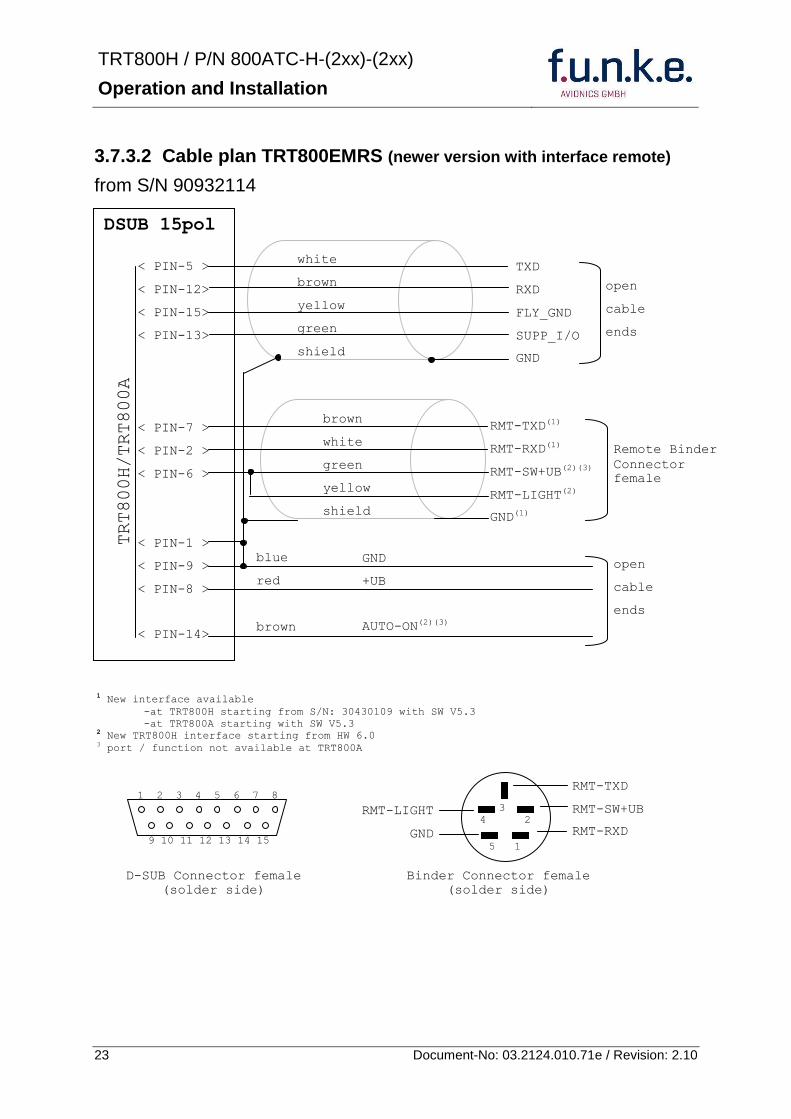
TRT800H PN 800ATC-H-(2xx)-(2xx)
Operation and Installation
24 Document-No 03212401071e Revision 210
3733 Cable plan TRT800EMSS (newer version without interface remote)
from SN 91032115
The External ndash Memory ndash Address - Adapter TRT800EMxx contains electronic parts and must not be opened Opening or modifying the connector leads to the loss of airworthiness certification
DSUB 15pol
TRT800HTRT800A
lt PIN-5 gt
lt PIN-12gt
lt PIN-15gt
lt PIN-13gt
lt PIN-1 gt
lt PIN-9 gt
lt PIN-8 gt
lt PIN-14gt
TXD
RXD
FLY_GND
SUPP_IO
GND
open
cable
ends
white
brown
yellow
green
shield
blue
red
brown
GND
+UB
AUTO-ON(2)(3)
open
cable
ends
2 New TRT800H interface starting from HW 60 3 port function not available at TRT800A
1 2 3 4 5 6 7 8
9 10 11 12 13 14 15
D-SUB Connector female
(solder side)
TRT800H PN 800ATC-H-(2xx)-(2xx)
Operation and Installation
25 Document-No 03212401071e Revision 210
38 Antenna
381 Antenna Selection
Recommended antennas see section 311 Accessories
Choose an antenna type compatible with the vehicle and the mounting location
Specified features depend on proper installation of the antenna
The radiation pattern needs to be verified considering aircraft type and mounting location
The electrical interference between the antenna and any other equipment must be taken into account in such a way that no reduction of the performance of any other system will occur
Install only certified antennas
382 Installation Recommendation
Take note of the antenna manufacturerrsquos instructions
The usually deployed Dipole- or Blade antennas necessarily require a high frequency capable solid metal ground plane at the antenna base
For installation in composite aircrafts ground planes are to be added The ground plane should be as large as possible but in any case not smaller than 10 cm x 10 cm If in doubt please contact the aircraft manufacturer
Keep away three feet from any other antenna
Pursue mounting in vertical position under the belly in flight direction
383 Antenna Wiring
Suitable antenna cables see section 311 Accessories
Keep wiring as short as possible
The smallest cable bend radius is 10cm Avoid sharp bends
Keep away from an ADF antenna cable at least 12 inches
Electrical connections to the antenna shall be protected against moisture to avoid loss of efficiency
TRT800H PN 800ATC-H-(2xx)-(2xx)
Operation and Installation
26 Document-No 03212401071e Revision 210
39 Post-Installation Check
All steering and control functions of the aircraft are to be examined in order to exclude disturbances by the wiring
The most important factor in the transponder configuration is the setting of the ICAO address (see section 454)
Attenuation from antenna to transponder at 1090 MHz must not exceed 15 dB
A certified maintenance shop must verify proper operation of the transponder by testing in accordance with Appendix F of ldquo14 CFR Part 43 ndash ATC Transponder Tests and Inspectionsrdquo
TRT800H PN 800ATC-H-(2xx)-(2xx)
Operation and Installation
27 Document-No 03212401071e Revision 210
310 Starting Up
Turn the transponder on with IO After start-up the following screens appear
311 Accessories
Part Number Description
TRKABEL1 Antenna cable 10 m (32 ft) TNC BNC
TRKABEL2 Antenna cable 25 m (82 ft) TNC BNC
TRKABEL3 Antenna cable 40 m (132 ft) TNC BNC
TRKABEL4 Antenna cable 65 m (213 ft) TNC BNC
TRT800EMRS External-Memory (Aircraft-Address-Adaptor) Connection cable with interface TRT-Remote control
CI-105 TransponderDME Antenna TSO C66b C74c
CI105 Comant Industries Inc
Height 325rdquo Weight 90 g (02 lbs)
AV22 Transponder Rod antenna TSO C74c
AV-22 R A Miller Industries
The TRT800H starts in standby mode (indicated with STBY) In order to change into operational mode (indicated with ACS) press MODE If ground switch is connected and status ldquoin flightrdquo is selected TRT800H starts in active mode
Very important is the correct configuration of the 24bit Aircraft-Address (see 454 General Setup)
TRT800H V53
FPGA-Vers 102
2000 FL 030
STBY 7000
TRT800H PN 800ATC-H-(2xx)-(2xx)
Operation and Installation
28 Document-No 03212401071e Revision 210
312 Drawings
3121 Dimensions
20mm15 mm
170 mm
TRT800TRT800H
65 mm
65
mm
Oslash 57 mm
Static Air
Antenna
PowerRS232
3122 Mounting Advices
Connections Area
8
0 m
m
Panel Cut-out
470 mm
470
mm
575 mm
4 x Oslash 4 mm
Oslash
Connector (plug) has to be clamped with both spring locks
No screws may be turned in more than max 15mm into the device ndash even if no hard limit is noticeable
Fixing clips (spring) left right
TRT800H PN 800ATC-H-(2xx)-(2xx)
Operation and Installation
29 Document-No 03212401071e Revision 210
4 TRANSPONDER SETTINGS
41 Overview
The TRT800H is capable of storing the following information
ICAO 24-Bit Aircraft-Address (AA)
Aircraft Category (AC)
Flight Identification (FID)
Ground-Switch (YesNo)
Speed Category (RI)
RS232 Interface Configuration
All of these data are configurable in the Setup and are stored in the external memory module integrated within the housing of the D-Sub connector (included in the delivery)
The cable with this connector shall remain in the aircraft even if the unit is removed to ensure that the ICAO 24bit aircraft address is fixed to the aircraft
Additionally the following usertransponder related settings are stored transponder internally
Active Squawk
Passive Squawk
VFR Squawk
Altitude offset
Display brightness
42 Display Configuration Summary
Transponder provides the opportunity to show summary of complete current settings To access configuration summary pages push and hold
ID in Standby mode Release ID if ldquoSHOW SETUPrdquo is displayed The summary is subdivided into the following pages
TRT800H PN 800ATC-H-(2xx)-(2xx)
Operation and Installation
30 Document-No 03212401071e Revision 210
Page 1
Aircraft Address
Aircraft Category
Flight Identification
MODE
Page 2 Speed Category
Ground Switch option
Remote Header option
MODE
Page 3 RS-232 Settings
Protocol baud rate position (if available)1
MODE
Page 4 Altitude correction settings
(part 1)
MODE
Page 5 Altitude correction settings
(part 2)
Note 1 Position data will only be displayed if
a GPS protocol is set as interface protocol (NMEA FREEFLIGHT AR-NAV)
18000 ft 0ft 25000 ft + 100ft 35000 ft - 50ft
exit
ALTITUDE CORRECTION 2000 ft 0ft 10000 ft + 100ft next
RS-232 NMEA Baud 4800 Pos 481 99 next
Speed Cat 8 Ground Sw YES Remote Hd NO next
AA F E 1 2 3 4 AC 1 9 FID 4 4 E 1 2 3 next
TRT800H PN 800ATC-H-(2xx)-(2xx)
Operation and Installation
31 Document-No 03212401071e Revision 210
GPS receiver is connected and transmits data (if not ldquoPos no datardquo is displayed)
a valid position is transmitted (if not ldquoPos wrong datardquo is displayed)
While configuration summary page is displayed no new position data will be processed
43 General settings
431 ICAO 24-Bit Aircraft Address (AA)
Ask your national aviation authority (e g in Germany LBA Referat B5 Department ldquoVerkehrszulassungrdquo) how to obtain the AA In the case of aerial sports equipment the contact point would be the respective associations Only the assigned AA has to be used and must not be modified at any time because a duplicate address would jeopardize the data surveillance and integrity figures of Mode S
If no AA is stored after power on the display shows ldquoCRADLE OFFrdquo and the transponder operates in Mode AC
(Configuration of the AA see section 454)
432 Aircraft Category (AC)
Code Description Code Description
11 Emergency Vehicle 1C Ultra-Light Paraglider
12 Service Vehicle 1E Drone
19 Glider 21 Aircraft (D-Exxx) lt 15500 lbs Motor Glider (D-Kxxx)
1A Balloon amp Airship 22 Aircraft ge 15500 lbslt 75000 lbs
1B Paratrooper 27 Rotorcraft
Only one of the Codes mentioned in the table above must be used
Setuprarr454
Setuprarr454
TRT800H PN 800ATC-H-(2xx)-(2xx)
Operation and Installation
32 Document-No 03212401071e Revision 210
433 Flight-ID (FID)
Per ICAO regulation Mode-S data must contain a valid flight identification (FID) to ensure that the correlation between flight plan and radar data will work automatically
FID setting is required to correspond to the aircraft identification that has been specified at item 7 of the ICAO flight plan It contains seven characters at a maximum (left-aligned no additional zeros dashes or spacesblanks)
For an aircraft using a company call sign the Flight-ID mostly consists of the ICAO three-letter designator for the aircraft operator followed by an identification code eg KLM511 BAW213 JTR25
If no company call sign is used or no flight plan is filed the default FID to be set consists of the registration marking of the aircraft (eg DEABC) with no dashes spacesblanks or additional zeros even if they are included in the registration marking on the aircraft (tail number) While entering the FID into the transponder the last remaining digits must be filled with blanks
The ICAO Flight Plan only specifies 7 characters for FID funke AVIONICS reserves 8 characters as stated in ED-73B for further expansion of the flight plan
The user shall only program 7 characters for FID
Setuprarr454
TRT800H PN 800ATC-H-(2xx)-(2xx)
Operation and Installation
33 Document-No 03212401071e Revision 210
434 Reply Information - Speed Category (RI)
Besides AA AC and FID another important part of the Mode-S data is the Speed Category of the respective aircraft This speed category shall be configured in the setup and must contain one of the following codes
Code Description
08 No maximum airspeed data available
09 Maximum airspeed le 75 kt
10 75 kt gt maximum airspeed le 150 kt
11 150 kt gt maximum airspeed le 300 kt
12 300 kt gt maximum airspeed le 600 kt
13 600 kt gt maximum airspeed le 1200 kt
14 Maximum airspeed gt 1200 kt
15 Not assigned
44 Optional settings
441 Option Ground-Switch
If a ground switch is connected (and enabled in setup) the transponder is able to determine on-ground and in-flight state On-ground state is activated automatically once the gear touches the ground On-ground state is indicated on display by symbol G (apart from lsquoFrsquo for In-flight-state)
In On-ground-state the transponder will reply differently to certain addressed interrogations Also the transmission rate of some periodically sent data (squitters ADS-B) is reduced This allows ATC to distinguish between airborne aircraft and those on the ground and it reduces the Mode S channel load
For small aircraft authorities normally do not require such a ground switch In this case the transponder will use the same data formats on the ground as in the airborne state
Setuprarr454 Wiringrarr373
Setuprarr454
TRT800H PN 800ATC-H-(2xx)-(2xx)
Operation and Installation
34 Document-No 03212401071e Revision 210
442 Option Remote Header
The transponder provides a TRT800RT remote control interface If a remote header TRT800RT is connected transponder can be remote controlled via this interface Remote interface provides control of all standard user inputs available during standard operational mode For more information see TRT800RT manual Remote control interface de-activation is setup configurable Remote control interface must only be connected to TRT800RT
443 Serial Interface (RS232)
Using serial interface a GPS receiver can be connected to broadcast own position via ADS-B Out position message Position could be received by other appropriately equipped aircrafts and processed for collision avoidance ADS-B Out functionality
The ADS-B function of this device has not been evaluated during the FAA TSO certification process other than to ensure non-interference Due to the SW assurance of DAL D the ADS-B function cannot be used in the US National Airspace Connecting a GPS source will not comply to FAA certification requirements with regard to ADS-B
Supported formatsprotocols are
Option Description Baud rate
FREEFLIGHT GPSWAAS Sensor 1201
NexNav NNL 3101
19200
AR-NAV Bendix King
KLN 89B KLN 94 ldquoStandard RS232 Sentencerdquo
KMD 150 ldquoSentence Type 1rdquo
Garmin 400 Series ldquoSentence Type 1rdquo (with and without altitude data)
9600
NMEA NMEA-Format data format RMC is expected
4800
Setuprarr454 Wiringrarr373
Setuprarr454 Wiringrarr373
TRT800H PN 800ATC-H-(2xx)-(2xx)
Operation and Installation
35 Document-No 03212401071e Revision 210
Option Description Baud rate
FAVISIA Glass Cockpit support
FAVISIA Data format to be processed in FAVISIA avionics suite
-
FAVISIA+GPS Data format to be processed in FAVISIA avionics suite (output) and additional processing of incoming NMEA GPS-Receiver position data to support the ADS-B Out functionality
4800
Other
Comm-AB-support
Data format for special purpose An additional data link processor allows COMM-AB operation and processing of the position information of a flight management system simultaneously
38400
Disabled No communication via RS232 interface -
444 Altitude CorrectionOffset
The TRT800H has an integrated temperature compensated high-precision pressure sensor This sensor is factory-calibrated so that it will yield accurate flight level (uncorrected pressure altitude) within the entire altitude range
However due to differences in calibration of the TRT800H pressure sensor and the altimeter in the cockpit it may become necessary to adjust the TRT800H pressure readings so that the value indicated and transmitted by the TRT800H corresponds to the indication of the primary altimeter seen by the pilot within 125 feet (as specified in ETSO C88aSAE AS 8003)
Setting for all described GPS-systems
1 2 position messages per 2 sec
Setuprarr455
TRT800H PN 800ATC-H-(2xx)-(2xx)
Operation and Installation
36 Document-No 03212401071e Revision 210
The check for correspondence between the primary altimeter and the TRT800H is usually performed every 24 months as part of the aircrafts altimeter checks
Altitude correction is based on setup configurable offset values at five interpolation points ( 2000 8000 18000 25000 and 35000 ft)The offset value itself is limited to a range from -100 to + 100ft at each point (10ft steps)
45 Setup Procedure
Programming of the ICAOA 24-bit Aircraft Address and of the Aircraft Category shall be executed by qualified personnel only
A wrong Aircraft Address or Flight ID may cause serious problems ATC or with ACASTCAS systems
Pilot and owner are responsible for correctly set transponder data
451 Setup Menu Control
In order to access the functions described in the following paragraphs push and hold ID in Standby mode Release ID if desired counter value menu name is displayed to enter the menu The following menu entries are selectable
Count Displayed Name Function
03 FID FID is displayed
48 CHANGE FID Enter FID setup page
913 SHOW SETUP Enter setup summary listed on different pages (no changes possible)
2528 ENTER SETUP Enter transponder general configuration pages
3134 ALTITUDE CORRECTION
Enter altitude correction menu
TRT800H PN 800ATC-H-(2xx)-(2xx)
Operation and Installation
37 Document-No 03212401071e Revision 210
452 Transponder configurationrecord structure
Aircraft related parts of transponder configuration are stored in one out of eight possible records (record=presetting) Each record contains the following information
Aircraft Address (AA 24bit)
Aircraft category (AC)
Flight identification (FID 6-8 numbersletters)
RS-232 Interface setting (eg GPS protocol)
Ground-Switch setting (Installed YesNo)
Speed category (RI) of the respective aircraft
Remote Header setting (Installed YesNo)
User related settings (eg squawk codes display brightness) are stored once in one global record (transponder internally)
453 Transponder configurationrecord handling
At least one record is stored in external memory Up to 8 records can be additional be applied during setup process
If more than one record is applied the active record must be selected out of a list (determined by FID) during start-up of the transponder
Previously applied records can be deleted again by filling FID with zerorsquos only
454 General Setup
Any menu item can be passed by MODE If no changes are made the original settings will remain stored Modification of one menu item does not impact the others No entries will be deleted
TRT800H PN 800ATC-H-(2xx)-(2xx)
Operation and Installation
38 Document-No 03212401071e Revision 210
Step Display (Example)
1 Start-up Transponder
2 Ensure the transponder-mode is bdquoSTBYldquo If necessary change the mode by pressing MODE
3 Press ID A counter is shown at the upper-right corner Hold ID till ldquoENTER SETUPrdquo is displayed
4 After release of ID the first setup menu is displayed
5 helliphellipselect position (^)
rotary knobchange value
MODE
6 With the rotary knob you can select bdquoyesldquo if a Ground Switch is installed if not select ldquonordquo and proceed with step 7
MODE
Record 1
GND Switch YesNo
next
AA EF123456
AC 18
FID ^BCDEFG
next
AA EF123456
AC 18
FID ABCDEFG
next
ENTER SETUP 26
2000 FL 030
STBY 7000
TRT800H PN 800ATC-H-(2xx)-(2xx)
Operation and Installation
39 Document-No 03212401071e Revision 210
Step Display (Example)
7 At this stage the respective speed category shall be selected by using the rotary knob
MODE
8 At this stage a GPS receiver for ADS-B Out can be selected (Selectable by rotary knob)
MODE
9 At this stage remote interface for communication between TRT800H and remote header can be activated (Selectable by rotary knob)
Remote interface must only be activated if a remote header is connected
MODE
10 With ID further Records can now be created and configured as described in the aforementioned steps At start-up of the transponder one of the defined records with all associated configurations need to be selected
MODE
Records ID=Edit Records
EXIT
Record 1
REMOTE Header YesNo
next
Record 1
GPSINTEXT NMEA
next
Record 1
Speed Cat 08-15
next
TRT800H PN 800ATC-H-(2xx)-(2xx)
Operation and Installation
40 Document-No 03212401071e Revision 210
Step Display (Example)
11 You have now left the configuration mode and are back in normal operation
12 Switch off the transponder
13 Switch on the transponder Your ICAO 24-Bit Aircraft Address is now stored
TRT800H V53
FPGA-Vers 102
2000 FL 030
STBY 7000
TRT800H PN 800ATC-H-(2xx)-(2xx)
Operation and Installation
41 Document-No 03212401071e Revision 210
455 Altitude Correction Setup
Altitude correction setup shall be executed by qualified personnel only
Pilot and owner are responsible for correctly set altitude offset values
The usesetting of altitude correction values is only necessary in exceptional cases (see 444 for details)
Altitude correction is based on five interpolation points ( 2000 10000 18000 25000 and 35000 ft)The offset value at each interpolation point can be adjusted in a range from -100 to + 100ft at each point (10ft steps) Offset values set to zero at each interpolation point deactivates altitude correction (defaultfactory setting)
Step Display (Example)
1 Start-up Transponder
2 Ensure the transponder-mode is bdquoSTBYldquo If necessary change the mode by pressing MODE
3 Press ID A counter is shown at the upper-right corner Hold ID till ldquoALTITUDE OFFSETrdquo is displayed
ALTITUDE OFFSET 33
2000 FL 030
STBY 7000
Descriptionrarr444
TRT800H PN 800ATC-H-(2xx)-(2xx)
Operation and Installation
42 Document-No 03212401071e Revision 210
Step Display (Example)
4 After release of ID the first altitude level + corresponding offset value is displayed
5 Change offset value with rotary knob
MODE
6 (9) Repeat last step for another 4 altitude levels 10000ft 18000ft 25000ft 35000ft
MODE
10 You have now left the configuration mode and are back in normal operation
Switch off the transponder
11 Switch on the transponder New altitude offset values will now be used for altitude calculation
Altitude 10000 ft
Offset 0 ft
nextexit
Altitude 2000 ft
Offset 0 ft
next
TRT800H V53
FPGA-Vers 102
2000 FL 030
STBY 7000
Altitude 2000 ft
Offset 0 ft
next
TRT800H PN 800ATC-H-(2xx)-(2xx)
Operation and Installation
43 Document-No 03212401071e Revision 210
5 APPENDIX
51 Technical Data
Compliance CS-ETSO-2C112a
EASA21O269
FAA TSO-C112c
Applicable Documents CS-ETSO-2C112a
FAA TSO-C112c
EUROCAE ED-73C Class 1 Level 2es
RTCA DO-181D Class 1 Level 2es
EUROCAE ED-26
RTCA DO-160D
RTCA DO-178B Software-Level D
Temperature Ranges
Operation -20 degC to +55 degC for 30 min +70degC
Storage -55 degC to +85 degC
Altitude Range le 35 000 ft
Speed Range le 250 kt (TAS)
Shock 6 G Operation
20 G crash safety
Environmental Categories RTCA DO-160D EnvCat [C1Z]CAA[SM]XXXXXXZBAAA[TT]M[B3F3]XXA
Power Supply 138 VDC (10 VDC 16 VDC)
040 A 138 VDC (typ)
070 A 138 VDC (max)
10 W (max)
TRT800H PN 800ATC-H-(2xx)-(2xx)
Operation and Installation
44 Document-No 03212401071e Revision 210
Fuse External 2A-slow-blow fuse
Mounting Panel cut-out d=575 mm
Weight 06 kg (132 lbs)
Receiver Characteristics
Sensitivity
RF input power level resulting in a 90 reply rate
A MTL for ATCRBS and ATCRBSMode S All-Call interrogations -74 dBm plusmn3 dB
B MTL for Mode S interrogations -74 dBm plusmn 3 dB
Reply transmission frequency
1090 plusmn 1 MHz
RF Peak Power Output 21 dBW (126 W) at antenna base (with maximum cable attenuation of 15 dB)
Squitter (ADS-B) transmitted at random intervals uniformly distributed over the range from 08 to 12 seconds full self-verification of data and occurrence
Mode S Elementary Surveillance
ICAO 24-bit Aircraft Address (Hex-Code)
aircraft address as assigned by national aviation authority
FID Flight ID Flight Plan call sign or aircraft registration marking
Capability Report Reports the available data and means by which the transponder can report
Pressure Altitude Up to 35 000 ft in 25 ft increments
Flight Status in-flight on-ground
Mode S Enhanced Surveillance
Level 2es Comm-A Comm-B 56112-Bit-Messages
SI-capability
TRT800H PN 800ATC-H-(2xx)-(2xx)
Operation and Installation
45 Document-No 03212401071e Revision 210
52 Environmental Conditions
Characteristic DOndash160D Section Cat Condition
Temperature Altitude 40
C1
Low ground survival temperature
451 ndash 55degC
Low operating temperature 451 ndash 20degC
High ground survival Temperature
452 + 85degC
High Short-time Operating Temperature
452 + 70degC
High Operating Temperature 453 + 55degC
In-Flight Loss of Cooling 454 Z No auxiliary cooling required
Altitude 461 C1 35 000 ft
Temperature Variation 50 C 2degC change rate minimum per minute
Humidity 60 A
Shock 70 A
6 G operational shocks
20 G Crash Safety
Test Type R in all 6 directions
Vibration 80 S Vibration Curve M
Explosion Proofness 90 X No test required
Water Proofness 100 X No test required
Fluids Susceptibilities 110 X No test required
Sand and Dust 120 X No test required
Fungus Resistance 130 X No test required
Salt Spray 140 X No test required
Magnetic Effect 150 Z Less than 03 m
Power Input (DC) 160 B
Voltage Spike Conducted 170 A
Audio Frequency Conducted Susceptibility
180 A
TRT800H PN 800ATC-H-(2xx)-(2xx)
Operation and Installation
46 Document-No 03212401071e Revision 210
Characteristic DOndash160D Section Cat Condition
Induced Signal Susceptibility 190 A
Radio Frequency Susceptibility
200 TT
Emission of RF Energy 210 M
Lightning Induced Transient Susceptibility
220 B3F3
Lightning Direct Effects 230 X No test required
Icing 240 X No test required
Electrostatic Discharge (ESD) 250 A
53 DO-178B Open Problem Reports
There are no open problem reports for the software of this device
TRT800H PN 800ATC-H-(2xx)-(2xx)
Operation and Installation
47 Document-No 03212401071e Revision 210
Notes
f funke funke means ndash fabrication utilities network know-how engineering
funke AVIONICS GmbH Heinz-Strachowitz-Str 4
DE-86807 Buchloe Germany
phone +49-8241 80066 0
fax +49-8241 80066 99 E-mail
servicefunkeavionicsde wwwfunkeavionicsde
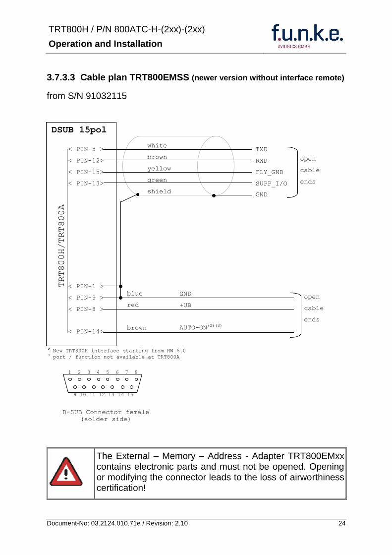
TRT800H PN 800ATC-H-(2xx)-(2xx)
Operation and Installation
25 Document-No 03212401071e Revision 210
38 Antenna
381 Antenna Selection
Recommended antennas see section 311 Accessories
Choose an antenna type compatible with the vehicle and the mounting location
Specified features depend on proper installation of the antenna
The radiation pattern needs to be verified considering aircraft type and mounting location
The electrical interference between the antenna and any other equipment must be taken into account in such a way that no reduction of the performance of any other system will occur
Install only certified antennas
382 Installation Recommendation
Take note of the antenna manufacturerrsquos instructions
The usually deployed Dipole- or Blade antennas necessarily require a high frequency capable solid metal ground plane at the antenna base
For installation in composite aircrafts ground planes are to be added The ground plane should be as large as possible but in any case not smaller than 10 cm x 10 cm If in doubt please contact the aircraft manufacturer
Keep away three feet from any other antenna
Pursue mounting in vertical position under the belly in flight direction
383 Antenna Wiring
Suitable antenna cables see section 311 Accessories
Keep wiring as short as possible
The smallest cable bend radius is 10cm Avoid sharp bends
Keep away from an ADF antenna cable at least 12 inches
Electrical connections to the antenna shall be protected against moisture to avoid loss of efficiency
TRT800H PN 800ATC-H-(2xx)-(2xx)
Operation and Installation
26 Document-No 03212401071e Revision 210
39 Post-Installation Check
All steering and control functions of the aircraft are to be examined in order to exclude disturbances by the wiring
The most important factor in the transponder configuration is the setting of the ICAO address (see section 454)
Attenuation from antenna to transponder at 1090 MHz must not exceed 15 dB
A certified maintenance shop must verify proper operation of the transponder by testing in accordance with Appendix F of ldquo14 CFR Part 43 ndash ATC Transponder Tests and Inspectionsrdquo
TRT800H PN 800ATC-H-(2xx)-(2xx)
Operation and Installation
27 Document-No 03212401071e Revision 210
310 Starting Up
Turn the transponder on with IO After start-up the following screens appear
311 Accessories
Part Number Description
TRKABEL1 Antenna cable 10 m (32 ft) TNC BNC
TRKABEL2 Antenna cable 25 m (82 ft) TNC BNC
TRKABEL3 Antenna cable 40 m (132 ft) TNC BNC
TRKABEL4 Antenna cable 65 m (213 ft) TNC BNC
TRT800EMRS External-Memory (Aircraft-Address-Adaptor) Connection cable with interface TRT-Remote control
CI-105 TransponderDME Antenna TSO C66b C74c
CI105 Comant Industries Inc
Height 325rdquo Weight 90 g (02 lbs)
AV22 Transponder Rod antenna TSO C74c
AV-22 R A Miller Industries
The TRT800H starts in standby mode (indicated with STBY) In order to change into operational mode (indicated with ACS) press MODE If ground switch is connected and status ldquoin flightrdquo is selected TRT800H starts in active mode
Very important is the correct configuration of the 24bit Aircraft-Address (see 454 General Setup)
TRT800H V53
FPGA-Vers 102
2000 FL 030
STBY 7000
TRT800H PN 800ATC-H-(2xx)-(2xx)
Operation and Installation
28 Document-No 03212401071e Revision 210
312 Drawings
3121 Dimensions
20mm15 mm
170 mm
TRT800TRT800H
65 mm
65
mm
Oslash 57 mm
Static Air
Antenna
PowerRS232
3122 Mounting Advices
Connections Area
8
0 m
m
Panel Cut-out
470 mm
470
mm
575 mm
4 x Oslash 4 mm
Oslash
Connector (plug) has to be clamped with both spring locks
No screws may be turned in more than max 15mm into the device ndash even if no hard limit is noticeable
Fixing clips (spring) left right
TRT800H PN 800ATC-H-(2xx)-(2xx)
Operation and Installation
29 Document-No 03212401071e Revision 210
4 TRANSPONDER SETTINGS
41 Overview
The TRT800H is capable of storing the following information
ICAO 24-Bit Aircraft-Address (AA)
Aircraft Category (AC)
Flight Identification (FID)
Ground-Switch (YesNo)
Speed Category (RI)
RS232 Interface Configuration
All of these data are configurable in the Setup and are stored in the external memory module integrated within the housing of the D-Sub connector (included in the delivery)
The cable with this connector shall remain in the aircraft even if the unit is removed to ensure that the ICAO 24bit aircraft address is fixed to the aircraft
Additionally the following usertransponder related settings are stored transponder internally
Active Squawk
Passive Squawk
VFR Squawk
Altitude offset
Display brightness
42 Display Configuration Summary
Transponder provides the opportunity to show summary of complete current settings To access configuration summary pages push and hold
ID in Standby mode Release ID if ldquoSHOW SETUPrdquo is displayed The summary is subdivided into the following pages
TRT800H PN 800ATC-H-(2xx)-(2xx)
Operation and Installation
30 Document-No 03212401071e Revision 210
Page 1
Aircraft Address
Aircraft Category
Flight Identification
MODE
Page 2 Speed Category
Ground Switch option
Remote Header option
MODE
Page 3 RS-232 Settings
Protocol baud rate position (if available)1
MODE
Page 4 Altitude correction settings
(part 1)
MODE
Page 5 Altitude correction settings
(part 2)
Note 1 Position data will only be displayed if
a GPS protocol is set as interface protocol (NMEA FREEFLIGHT AR-NAV)
18000 ft 0ft 25000 ft + 100ft 35000 ft - 50ft
exit
ALTITUDE CORRECTION 2000 ft 0ft 10000 ft + 100ft next
RS-232 NMEA Baud 4800 Pos 481 99 next
Speed Cat 8 Ground Sw YES Remote Hd NO next
AA F E 1 2 3 4 AC 1 9 FID 4 4 E 1 2 3 next
TRT800H PN 800ATC-H-(2xx)-(2xx)
Operation and Installation
31 Document-No 03212401071e Revision 210
GPS receiver is connected and transmits data (if not ldquoPos no datardquo is displayed)
a valid position is transmitted (if not ldquoPos wrong datardquo is displayed)
While configuration summary page is displayed no new position data will be processed
43 General settings
431 ICAO 24-Bit Aircraft Address (AA)
Ask your national aviation authority (e g in Germany LBA Referat B5 Department ldquoVerkehrszulassungrdquo) how to obtain the AA In the case of aerial sports equipment the contact point would be the respective associations Only the assigned AA has to be used and must not be modified at any time because a duplicate address would jeopardize the data surveillance and integrity figures of Mode S
If no AA is stored after power on the display shows ldquoCRADLE OFFrdquo and the transponder operates in Mode AC
(Configuration of the AA see section 454)
432 Aircraft Category (AC)
Code Description Code Description
11 Emergency Vehicle 1C Ultra-Light Paraglider
12 Service Vehicle 1E Drone
19 Glider 21 Aircraft (D-Exxx) lt 15500 lbs Motor Glider (D-Kxxx)
1A Balloon amp Airship 22 Aircraft ge 15500 lbslt 75000 lbs
1B Paratrooper 27 Rotorcraft
Only one of the Codes mentioned in the table above must be used
Setuprarr454
Setuprarr454
TRT800H PN 800ATC-H-(2xx)-(2xx)
Operation and Installation
32 Document-No 03212401071e Revision 210
433 Flight-ID (FID)
Per ICAO regulation Mode-S data must contain a valid flight identification (FID) to ensure that the correlation between flight plan and radar data will work automatically
FID setting is required to correspond to the aircraft identification that has been specified at item 7 of the ICAO flight plan It contains seven characters at a maximum (left-aligned no additional zeros dashes or spacesblanks)
For an aircraft using a company call sign the Flight-ID mostly consists of the ICAO three-letter designator for the aircraft operator followed by an identification code eg KLM511 BAW213 JTR25
If no company call sign is used or no flight plan is filed the default FID to be set consists of the registration marking of the aircraft (eg DEABC) with no dashes spacesblanks or additional zeros even if they are included in the registration marking on the aircraft (tail number) While entering the FID into the transponder the last remaining digits must be filled with blanks
The ICAO Flight Plan only specifies 7 characters for FID funke AVIONICS reserves 8 characters as stated in ED-73B for further expansion of the flight plan
The user shall only program 7 characters for FID
Setuprarr454
TRT800H PN 800ATC-H-(2xx)-(2xx)
Operation and Installation
33 Document-No 03212401071e Revision 210
434 Reply Information - Speed Category (RI)
Besides AA AC and FID another important part of the Mode-S data is the Speed Category of the respective aircraft This speed category shall be configured in the setup and must contain one of the following codes
Code Description
08 No maximum airspeed data available
09 Maximum airspeed le 75 kt
10 75 kt gt maximum airspeed le 150 kt
11 150 kt gt maximum airspeed le 300 kt
12 300 kt gt maximum airspeed le 600 kt
13 600 kt gt maximum airspeed le 1200 kt
14 Maximum airspeed gt 1200 kt
15 Not assigned
44 Optional settings
441 Option Ground-Switch
If a ground switch is connected (and enabled in setup) the transponder is able to determine on-ground and in-flight state On-ground state is activated automatically once the gear touches the ground On-ground state is indicated on display by symbol G (apart from lsquoFrsquo for In-flight-state)
In On-ground-state the transponder will reply differently to certain addressed interrogations Also the transmission rate of some periodically sent data (squitters ADS-B) is reduced This allows ATC to distinguish between airborne aircraft and those on the ground and it reduces the Mode S channel load
For small aircraft authorities normally do not require such a ground switch In this case the transponder will use the same data formats on the ground as in the airborne state
Setuprarr454 Wiringrarr373
Setuprarr454
TRT800H PN 800ATC-H-(2xx)-(2xx)
Operation and Installation
34 Document-No 03212401071e Revision 210
442 Option Remote Header
The transponder provides a TRT800RT remote control interface If a remote header TRT800RT is connected transponder can be remote controlled via this interface Remote interface provides control of all standard user inputs available during standard operational mode For more information see TRT800RT manual Remote control interface de-activation is setup configurable Remote control interface must only be connected to TRT800RT
443 Serial Interface (RS232)
Using serial interface a GPS receiver can be connected to broadcast own position via ADS-B Out position message Position could be received by other appropriately equipped aircrafts and processed for collision avoidance ADS-B Out functionality
The ADS-B function of this device has not been evaluated during the FAA TSO certification process other than to ensure non-interference Due to the SW assurance of DAL D the ADS-B function cannot be used in the US National Airspace Connecting a GPS source will not comply to FAA certification requirements with regard to ADS-B
Supported formatsprotocols are
Option Description Baud rate
FREEFLIGHT GPSWAAS Sensor 1201
NexNav NNL 3101
19200
AR-NAV Bendix King
KLN 89B KLN 94 ldquoStandard RS232 Sentencerdquo
KMD 150 ldquoSentence Type 1rdquo
Garmin 400 Series ldquoSentence Type 1rdquo (with and without altitude data)
9600
NMEA NMEA-Format data format RMC is expected
4800
Setuprarr454 Wiringrarr373
Setuprarr454 Wiringrarr373
TRT800H PN 800ATC-H-(2xx)-(2xx)
Operation and Installation
35 Document-No 03212401071e Revision 210
Option Description Baud rate
FAVISIA Glass Cockpit support
FAVISIA Data format to be processed in FAVISIA avionics suite
-
FAVISIA+GPS Data format to be processed in FAVISIA avionics suite (output) and additional processing of incoming NMEA GPS-Receiver position data to support the ADS-B Out functionality
4800
Other
Comm-AB-support
Data format for special purpose An additional data link processor allows COMM-AB operation and processing of the position information of a flight management system simultaneously
38400
Disabled No communication via RS232 interface -
444 Altitude CorrectionOffset
The TRT800H has an integrated temperature compensated high-precision pressure sensor This sensor is factory-calibrated so that it will yield accurate flight level (uncorrected pressure altitude) within the entire altitude range
However due to differences in calibration of the TRT800H pressure sensor and the altimeter in the cockpit it may become necessary to adjust the TRT800H pressure readings so that the value indicated and transmitted by the TRT800H corresponds to the indication of the primary altimeter seen by the pilot within 125 feet (as specified in ETSO C88aSAE AS 8003)
Setting for all described GPS-systems
1 2 position messages per 2 sec
Setuprarr455
TRT800H PN 800ATC-H-(2xx)-(2xx)
Operation and Installation
36 Document-No 03212401071e Revision 210
The check for correspondence between the primary altimeter and the TRT800H is usually performed every 24 months as part of the aircrafts altimeter checks
Altitude correction is based on setup configurable offset values at five interpolation points ( 2000 8000 18000 25000 and 35000 ft)The offset value itself is limited to a range from -100 to + 100ft at each point (10ft steps)
45 Setup Procedure
Programming of the ICAOA 24-bit Aircraft Address and of the Aircraft Category shall be executed by qualified personnel only
A wrong Aircraft Address or Flight ID may cause serious problems ATC or with ACASTCAS systems
Pilot and owner are responsible for correctly set transponder data
451 Setup Menu Control
In order to access the functions described in the following paragraphs push and hold ID in Standby mode Release ID if desired counter value menu name is displayed to enter the menu The following menu entries are selectable
Count Displayed Name Function
03 FID FID is displayed
48 CHANGE FID Enter FID setup page
913 SHOW SETUP Enter setup summary listed on different pages (no changes possible)
2528 ENTER SETUP Enter transponder general configuration pages
3134 ALTITUDE CORRECTION
Enter altitude correction menu
TRT800H PN 800ATC-H-(2xx)-(2xx)
Operation and Installation
37 Document-No 03212401071e Revision 210
452 Transponder configurationrecord structure
Aircraft related parts of transponder configuration are stored in one out of eight possible records (record=presetting) Each record contains the following information
Aircraft Address (AA 24bit)
Aircraft category (AC)
Flight identification (FID 6-8 numbersletters)
RS-232 Interface setting (eg GPS protocol)
Ground-Switch setting (Installed YesNo)
Speed category (RI) of the respective aircraft
Remote Header setting (Installed YesNo)
User related settings (eg squawk codes display brightness) are stored once in one global record (transponder internally)
453 Transponder configurationrecord handling
At least one record is stored in external memory Up to 8 records can be additional be applied during setup process
If more than one record is applied the active record must be selected out of a list (determined by FID) during start-up of the transponder
Previously applied records can be deleted again by filling FID with zerorsquos only
454 General Setup
Any menu item can be passed by MODE If no changes are made the original settings will remain stored Modification of one menu item does not impact the others No entries will be deleted
TRT800H PN 800ATC-H-(2xx)-(2xx)
Operation and Installation
38 Document-No 03212401071e Revision 210
Step Display (Example)
1 Start-up Transponder
2 Ensure the transponder-mode is bdquoSTBYldquo If necessary change the mode by pressing MODE
3 Press ID A counter is shown at the upper-right corner Hold ID till ldquoENTER SETUPrdquo is displayed
4 After release of ID the first setup menu is displayed
5 helliphellipselect position (^)
rotary knobchange value
MODE
6 With the rotary knob you can select bdquoyesldquo if a Ground Switch is installed if not select ldquonordquo and proceed with step 7
MODE
Record 1
GND Switch YesNo
next
AA EF123456
AC 18
FID ^BCDEFG
next
AA EF123456
AC 18
FID ABCDEFG
next
ENTER SETUP 26
2000 FL 030
STBY 7000
TRT800H PN 800ATC-H-(2xx)-(2xx)
Operation and Installation
39 Document-No 03212401071e Revision 210
Step Display (Example)
7 At this stage the respective speed category shall be selected by using the rotary knob
MODE
8 At this stage a GPS receiver for ADS-B Out can be selected (Selectable by rotary knob)
MODE
9 At this stage remote interface for communication between TRT800H and remote header can be activated (Selectable by rotary knob)
Remote interface must only be activated if a remote header is connected
MODE
10 With ID further Records can now be created and configured as described in the aforementioned steps At start-up of the transponder one of the defined records with all associated configurations need to be selected
MODE
Records ID=Edit Records
EXIT
Record 1
REMOTE Header YesNo
next
Record 1
GPSINTEXT NMEA
next
Record 1
Speed Cat 08-15
next
TRT800H PN 800ATC-H-(2xx)-(2xx)
Operation and Installation
40 Document-No 03212401071e Revision 210
Step Display (Example)
11 You have now left the configuration mode and are back in normal operation
12 Switch off the transponder
13 Switch on the transponder Your ICAO 24-Bit Aircraft Address is now stored
TRT800H V53
FPGA-Vers 102
2000 FL 030
STBY 7000
TRT800H PN 800ATC-H-(2xx)-(2xx)
Operation and Installation
41 Document-No 03212401071e Revision 210
455 Altitude Correction Setup
Altitude correction setup shall be executed by qualified personnel only
Pilot and owner are responsible for correctly set altitude offset values
The usesetting of altitude correction values is only necessary in exceptional cases (see 444 for details)
Altitude correction is based on five interpolation points ( 2000 10000 18000 25000 and 35000 ft)The offset value at each interpolation point can be adjusted in a range from -100 to + 100ft at each point (10ft steps) Offset values set to zero at each interpolation point deactivates altitude correction (defaultfactory setting)
Step Display (Example)
1 Start-up Transponder
2 Ensure the transponder-mode is bdquoSTBYldquo If necessary change the mode by pressing MODE
3 Press ID A counter is shown at the upper-right corner Hold ID till ldquoALTITUDE OFFSETrdquo is displayed
ALTITUDE OFFSET 33
2000 FL 030
STBY 7000
Descriptionrarr444
TRT800H PN 800ATC-H-(2xx)-(2xx)
Operation and Installation
42 Document-No 03212401071e Revision 210
Step Display (Example)
4 After release of ID the first altitude level + corresponding offset value is displayed
5 Change offset value with rotary knob
MODE
6 (9) Repeat last step for another 4 altitude levels 10000ft 18000ft 25000ft 35000ft
MODE
10 You have now left the configuration mode and are back in normal operation
Switch off the transponder
11 Switch on the transponder New altitude offset values will now be used for altitude calculation
Altitude 10000 ft
Offset 0 ft
nextexit
Altitude 2000 ft
Offset 0 ft
next
TRT800H V53
FPGA-Vers 102
2000 FL 030
STBY 7000
Altitude 2000 ft
Offset 0 ft
next
TRT800H PN 800ATC-H-(2xx)-(2xx)
Operation and Installation
43 Document-No 03212401071e Revision 210
5 APPENDIX
51 Technical Data
Compliance CS-ETSO-2C112a
EASA21O269
FAA TSO-C112c
Applicable Documents CS-ETSO-2C112a
FAA TSO-C112c
EUROCAE ED-73C Class 1 Level 2es
RTCA DO-181D Class 1 Level 2es
EUROCAE ED-26
RTCA DO-160D
RTCA DO-178B Software-Level D
Temperature Ranges
Operation -20 degC to +55 degC for 30 min +70degC
Storage -55 degC to +85 degC
Altitude Range le 35 000 ft
Speed Range le 250 kt (TAS)
Shock 6 G Operation
20 G crash safety
Environmental Categories RTCA DO-160D EnvCat [C1Z]CAA[SM]XXXXXXZBAAA[TT]M[B3F3]XXA
Power Supply 138 VDC (10 VDC 16 VDC)
040 A 138 VDC (typ)
070 A 138 VDC (max)
10 W (max)
TRT800H PN 800ATC-H-(2xx)-(2xx)
Operation and Installation
44 Document-No 03212401071e Revision 210
Fuse External 2A-slow-blow fuse
Mounting Panel cut-out d=575 mm
Weight 06 kg (132 lbs)
Receiver Characteristics
Sensitivity
RF input power level resulting in a 90 reply rate
A MTL for ATCRBS and ATCRBSMode S All-Call interrogations -74 dBm plusmn3 dB
B MTL for Mode S interrogations -74 dBm plusmn 3 dB
Reply transmission frequency
1090 plusmn 1 MHz
RF Peak Power Output 21 dBW (126 W) at antenna base (with maximum cable attenuation of 15 dB)
Squitter (ADS-B) transmitted at random intervals uniformly distributed over the range from 08 to 12 seconds full self-verification of data and occurrence
Mode S Elementary Surveillance
ICAO 24-bit Aircraft Address (Hex-Code)
aircraft address as assigned by national aviation authority
FID Flight ID Flight Plan call sign or aircraft registration marking
Capability Report Reports the available data and means by which the transponder can report
Pressure Altitude Up to 35 000 ft in 25 ft increments
Flight Status in-flight on-ground
Mode S Enhanced Surveillance
Level 2es Comm-A Comm-B 56112-Bit-Messages
SI-capability
TRT800H PN 800ATC-H-(2xx)-(2xx)
Operation and Installation
45 Document-No 03212401071e Revision 210
52 Environmental Conditions
Characteristic DOndash160D Section Cat Condition
Temperature Altitude 40
C1
Low ground survival temperature
451 ndash 55degC
Low operating temperature 451 ndash 20degC
High ground survival Temperature
452 + 85degC
High Short-time Operating Temperature
452 + 70degC
High Operating Temperature 453 + 55degC
In-Flight Loss of Cooling 454 Z No auxiliary cooling required
Altitude 461 C1 35 000 ft
Temperature Variation 50 C 2degC change rate minimum per minute
Humidity 60 A
Shock 70 A
6 G operational shocks
20 G Crash Safety
Test Type R in all 6 directions
Vibration 80 S Vibration Curve M
Explosion Proofness 90 X No test required
Water Proofness 100 X No test required
Fluids Susceptibilities 110 X No test required
Sand and Dust 120 X No test required
Fungus Resistance 130 X No test required
Salt Spray 140 X No test required
Magnetic Effect 150 Z Less than 03 m
Power Input (DC) 160 B
Voltage Spike Conducted 170 A
Audio Frequency Conducted Susceptibility
180 A
TRT800H PN 800ATC-H-(2xx)-(2xx)
Operation and Installation
46 Document-No 03212401071e Revision 210
Characteristic DOndash160D Section Cat Condition
Induced Signal Susceptibility 190 A
Radio Frequency Susceptibility
200 TT
Emission of RF Energy 210 M
Lightning Induced Transient Susceptibility
220 B3F3
Lightning Direct Effects 230 X No test required
Icing 240 X No test required
Electrostatic Discharge (ESD) 250 A
53 DO-178B Open Problem Reports
There are no open problem reports for the software of this device
TRT800H PN 800ATC-H-(2xx)-(2xx)
Operation and Installation
47 Document-No 03212401071e Revision 210
Notes
f funke funke means ndash fabrication utilities network know-how engineering
funke AVIONICS GmbH Heinz-Strachowitz-Str 4
DE-86807 Buchloe Germany
phone +49-8241 80066 0
fax +49-8241 80066 99 E-mail
servicefunkeavionicsde wwwfunkeavionicsde
TRT800H PN 800ATC-H-(2xx)-(2xx)
Operation and Installation
27 Document-No 03212401071e Revision 210
310 Starting Up
Turn the transponder on with IO After start-up the following screens appear
311 Accessories
Part Number Description
TRKABEL1 Antenna cable 10 m (32 ft) TNC BNC
TRKABEL2 Antenna cable 25 m (82 ft) TNC BNC
TRKABEL3 Antenna cable 40 m (132 ft) TNC BNC
TRKABEL4 Antenna cable 65 m (213 ft) TNC BNC
TRT800EMRS External-Memory (Aircraft-Address-Adaptor) Connection cable with interface TRT-Remote control
CI-105 TransponderDME Antenna TSO C66b C74c
CI105 Comant Industries Inc
Height 325rdquo Weight 90 g (02 lbs)
AV22 Transponder Rod antenna TSO C74c
AV-22 R A Miller Industries
The TRT800H starts in standby mode (indicated with STBY) In order to change into operational mode (indicated with ACS) press MODE If ground switch is connected and status ldquoin flightrdquo is selected TRT800H starts in active mode
Very important is the correct configuration of the 24bit Aircraft-Address (see 454 General Setup)
TRT800H V53
FPGA-Vers 102
2000 FL 030
STBY 7000
TRT800H PN 800ATC-H-(2xx)-(2xx)
Operation and Installation
28 Document-No 03212401071e Revision 210
312 Drawings
3121 Dimensions
20mm15 mm
170 mm
TRT800TRT800H
65 mm
65
mm
Oslash 57 mm
Static Air
Antenna
PowerRS232
3122 Mounting Advices
Connections Area
8
0 m
m
Panel Cut-out
470 mm
470
mm
575 mm
4 x Oslash 4 mm
Oslash
Connector (plug) has to be clamped with both spring locks
No screws may be turned in more than max 15mm into the device ndash even if no hard limit is noticeable
Fixing clips (spring) left right
TRT800H PN 800ATC-H-(2xx)-(2xx)
Operation and Installation
29 Document-No 03212401071e Revision 210
4 TRANSPONDER SETTINGS
41 Overview
The TRT800H is capable of storing the following information
ICAO 24-Bit Aircraft-Address (AA)
Aircraft Category (AC)
Flight Identification (FID)
Ground-Switch (YesNo)
Speed Category (RI)
RS232 Interface Configuration
All of these data are configurable in the Setup and are stored in the external memory module integrated within the housing of the D-Sub connector (included in the delivery)
The cable with this connector shall remain in the aircraft even if the unit is removed to ensure that the ICAO 24bit aircraft address is fixed to the aircraft
Additionally the following usertransponder related settings are stored transponder internally
Active Squawk
Passive Squawk
VFR Squawk
Altitude offset
Display brightness
42 Display Configuration Summary
Transponder provides the opportunity to show summary of complete current settings To access configuration summary pages push and hold
ID in Standby mode Release ID if ldquoSHOW SETUPrdquo is displayed The summary is subdivided into the following pages
TRT800H PN 800ATC-H-(2xx)-(2xx)
Operation and Installation
30 Document-No 03212401071e Revision 210
Page 1
Aircraft Address
Aircraft Category
Flight Identification
MODE
Page 2 Speed Category
Ground Switch option
Remote Header option
MODE
Page 3 RS-232 Settings
Protocol baud rate position (if available)1
MODE
Page 4 Altitude correction settings
(part 1)
MODE
Page 5 Altitude correction settings
(part 2)
Note 1 Position data will only be displayed if
a GPS protocol is set as interface protocol (NMEA FREEFLIGHT AR-NAV)
18000 ft 0ft 25000 ft + 100ft 35000 ft - 50ft
exit
ALTITUDE CORRECTION 2000 ft 0ft 10000 ft + 100ft next
RS-232 NMEA Baud 4800 Pos 481 99 next
Speed Cat 8 Ground Sw YES Remote Hd NO next
AA F E 1 2 3 4 AC 1 9 FID 4 4 E 1 2 3 next
TRT800H PN 800ATC-H-(2xx)-(2xx)
Operation and Installation
31 Document-No 03212401071e Revision 210
GPS receiver is connected and transmits data (if not ldquoPos no datardquo is displayed)
a valid position is transmitted (if not ldquoPos wrong datardquo is displayed)
While configuration summary page is displayed no new position data will be processed
43 General settings
431 ICAO 24-Bit Aircraft Address (AA)
Ask your national aviation authority (e g in Germany LBA Referat B5 Department ldquoVerkehrszulassungrdquo) how to obtain the AA In the case of aerial sports equipment the contact point would be the respective associations Only the assigned AA has to be used and must not be modified at any time because a duplicate address would jeopardize the data surveillance and integrity figures of Mode S
If no AA is stored after power on the display shows ldquoCRADLE OFFrdquo and the transponder operates in Mode AC
(Configuration of the AA see section 454)
432 Aircraft Category (AC)
Code Description Code Description
11 Emergency Vehicle 1C Ultra-Light Paraglider
12 Service Vehicle 1E Drone
19 Glider 21 Aircraft (D-Exxx) lt 15500 lbs Motor Glider (D-Kxxx)
1A Balloon amp Airship 22 Aircraft ge 15500 lbslt 75000 lbs
1B Paratrooper 27 Rotorcraft
Only one of the Codes mentioned in the table above must be used
Setuprarr454
Setuprarr454
TRT800H PN 800ATC-H-(2xx)-(2xx)
Operation and Installation
32 Document-No 03212401071e Revision 210
433 Flight-ID (FID)
Per ICAO regulation Mode-S data must contain a valid flight identification (FID) to ensure that the correlation between flight plan and radar data will work automatically
FID setting is required to correspond to the aircraft identification that has been specified at item 7 of the ICAO flight plan It contains seven characters at a maximum (left-aligned no additional zeros dashes or spacesblanks)
For an aircraft using a company call sign the Flight-ID mostly consists of the ICAO three-letter designator for the aircraft operator followed by an identification code eg KLM511 BAW213 JTR25
If no company call sign is used or no flight plan is filed the default FID to be set consists of the registration marking of the aircraft (eg DEABC) with no dashes spacesblanks or additional zeros even if they are included in the registration marking on the aircraft (tail number) While entering the FID into the transponder the last remaining digits must be filled with blanks
The ICAO Flight Plan only specifies 7 characters for FID funke AVIONICS reserves 8 characters as stated in ED-73B for further expansion of the flight plan
The user shall only program 7 characters for FID
Setuprarr454
TRT800H PN 800ATC-H-(2xx)-(2xx)
Operation and Installation
33 Document-No 03212401071e Revision 210
434 Reply Information - Speed Category (RI)
Besides AA AC and FID another important part of the Mode-S data is the Speed Category of the respective aircraft This speed category shall be configured in the setup and must contain one of the following codes
Code Description
08 No maximum airspeed data available
09 Maximum airspeed le 75 kt
10 75 kt gt maximum airspeed le 150 kt
11 150 kt gt maximum airspeed le 300 kt
12 300 kt gt maximum airspeed le 600 kt
13 600 kt gt maximum airspeed le 1200 kt
14 Maximum airspeed gt 1200 kt
15 Not assigned
44 Optional settings
441 Option Ground-Switch
If a ground switch is connected (and enabled in setup) the transponder is able to determine on-ground and in-flight state On-ground state is activated automatically once the gear touches the ground On-ground state is indicated on display by symbol G (apart from lsquoFrsquo for In-flight-state)
In On-ground-state the transponder will reply differently to certain addressed interrogations Also the transmission rate of some periodically sent data (squitters ADS-B) is reduced This allows ATC to distinguish between airborne aircraft and those on the ground and it reduces the Mode S channel load
For small aircraft authorities normally do not require such a ground switch In this case the transponder will use the same data formats on the ground as in the airborne state
Setuprarr454 Wiringrarr373
Setuprarr454
TRT800H PN 800ATC-H-(2xx)-(2xx)
Operation and Installation
34 Document-No 03212401071e Revision 210
442 Option Remote Header
The transponder provides a TRT800RT remote control interface If a remote header TRT800RT is connected transponder can be remote controlled via this interface Remote interface provides control of all standard user inputs available during standard operational mode For more information see TRT800RT manual Remote control interface de-activation is setup configurable Remote control interface must only be connected to TRT800RT
443 Serial Interface (RS232)
Using serial interface a GPS receiver can be connected to broadcast own position via ADS-B Out position message Position could be received by other appropriately equipped aircrafts and processed for collision avoidance ADS-B Out functionality
The ADS-B function of this device has not been evaluated during the FAA TSO certification process other than to ensure non-interference Due to the SW assurance of DAL D the ADS-B function cannot be used in the US National Airspace Connecting a GPS source will not comply to FAA certification requirements with regard to ADS-B
Supported formatsprotocols are
Option Description Baud rate
FREEFLIGHT GPSWAAS Sensor 1201
NexNav NNL 3101
19200
AR-NAV Bendix King
KLN 89B KLN 94 ldquoStandard RS232 Sentencerdquo
KMD 150 ldquoSentence Type 1rdquo
Garmin 400 Series ldquoSentence Type 1rdquo (with and without altitude data)
9600
NMEA NMEA-Format data format RMC is expected
4800
Setuprarr454 Wiringrarr373
Setuprarr454 Wiringrarr373
TRT800H PN 800ATC-H-(2xx)-(2xx)
Operation and Installation
35 Document-No 03212401071e Revision 210
Option Description Baud rate
FAVISIA Glass Cockpit support
FAVISIA Data format to be processed in FAVISIA avionics suite
-
FAVISIA+GPS Data format to be processed in FAVISIA avionics suite (output) and additional processing of incoming NMEA GPS-Receiver position data to support the ADS-B Out functionality
4800
Other
Comm-AB-support
Data format for special purpose An additional data link processor allows COMM-AB operation and processing of the position information of a flight management system simultaneously
38400
Disabled No communication via RS232 interface -
444 Altitude CorrectionOffset
The TRT800H has an integrated temperature compensated high-precision pressure sensor This sensor is factory-calibrated so that it will yield accurate flight level (uncorrected pressure altitude) within the entire altitude range
However due to differences in calibration of the TRT800H pressure sensor and the altimeter in the cockpit it may become necessary to adjust the TRT800H pressure readings so that the value indicated and transmitted by the TRT800H corresponds to the indication of the primary altimeter seen by the pilot within 125 feet (as specified in ETSO C88aSAE AS 8003)
Setting for all described GPS-systems
1 2 position messages per 2 sec
Setuprarr455
TRT800H PN 800ATC-H-(2xx)-(2xx)
Operation and Installation
36 Document-No 03212401071e Revision 210
The check for correspondence between the primary altimeter and the TRT800H is usually performed every 24 months as part of the aircrafts altimeter checks
Altitude correction is based on setup configurable offset values at five interpolation points ( 2000 8000 18000 25000 and 35000 ft)The offset value itself is limited to a range from -100 to + 100ft at each point (10ft steps)
45 Setup Procedure
Programming of the ICAOA 24-bit Aircraft Address and of the Aircraft Category shall be executed by qualified personnel only
A wrong Aircraft Address or Flight ID may cause serious problems ATC or with ACASTCAS systems
Pilot and owner are responsible for correctly set transponder data
451 Setup Menu Control
In order to access the functions described in the following paragraphs push and hold ID in Standby mode Release ID if desired counter value menu name is displayed to enter the menu The following menu entries are selectable
Count Displayed Name Function
03 FID FID is displayed
48 CHANGE FID Enter FID setup page
913 SHOW SETUP Enter setup summary listed on different pages (no changes possible)
2528 ENTER SETUP Enter transponder general configuration pages
3134 ALTITUDE CORRECTION
Enter altitude correction menu
TRT800H PN 800ATC-H-(2xx)-(2xx)
Operation and Installation
37 Document-No 03212401071e Revision 210
452 Transponder configurationrecord structure
Aircraft related parts of transponder configuration are stored in one out of eight possible records (record=presetting) Each record contains the following information
Aircraft Address (AA 24bit)
Aircraft category (AC)
Flight identification (FID 6-8 numbersletters)
RS-232 Interface setting (eg GPS protocol)
Ground-Switch setting (Installed YesNo)
Speed category (RI) of the respective aircraft
Remote Header setting (Installed YesNo)
User related settings (eg squawk codes display brightness) are stored once in one global record (transponder internally)
453 Transponder configurationrecord handling
At least one record is stored in external memory Up to 8 records can be additional be applied during setup process
If more than one record is applied the active record must be selected out of a list (determined by FID) during start-up of the transponder
Previously applied records can be deleted again by filling FID with zerorsquos only
454 General Setup
Any menu item can be passed by MODE If no changes are made the original settings will remain stored Modification of one menu item does not impact the others No entries will be deleted
TRT800H PN 800ATC-H-(2xx)-(2xx)
Operation and Installation
38 Document-No 03212401071e Revision 210
Step Display (Example)
1 Start-up Transponder
2 Ensure the transponder-mode is bdquoSTBYldquo If necessary change the mode by pressing MODE
3 Press ID A counter is shown at the upper-right corner Hold ID till ldquoENTER SETUPrdquo is displayed
4 After release of ID the first setup menu is displayed
5 helliphellipselect position (^)
rotary knobchange value
MODE
6 With the rotary knob you can select bdquoyesldquo if a Ground Switch is installed if not select ldquonordquo and proceed with step 7
MODE
Record 1
GND Switch YesNo
next
AA EF123456
AC 18
FID ^BCDEFG
next
AA EF123456
AC 18
FID ABCDEFG
next
ENTER SETUP 26
2000 FL 030
STBY 7000
TRT800H PN 800ATC-H-(2xx)-(2xx)
Operation and Installation
39 Document-No 03212401071e Revision 210
Step Display (Example)
7 At this stage the respective speed category shall be selected by using the rotary knob
MODE
8 At this stage a GPS receiver for ADS-B Out can be selected (Selectable by rotary knob)
MODE
9 At this stage remote interface for communication between TRT800H and remote header can be activated (Selectable by rotary knob)
Remote interface must only be activated if a remote header is connected
MODE
10 With ID further Records can now be created and configured as described in the aforementioned steps At start-up of the transponder one of the defined records with all associated configurations need to be selected
MODE
Records ID=Edit Records
EXIT
Record 1
REMOTE Header YesNo
next
Record 1
GPSINTEXT NMEA
next
Record 1
Speed Cat 08-15
next
TRT800H PN 800ATC-H-(2xx)-(2xx)
Operation and Installation
40 Document-No 03212401071e Revision 210
Step Display (Example)
11 You have now left the configuration mode and are back in normal operation
12 Switch off the transponder
13 Switch on the transponder Your ICAO 24-Bit Aircraft Address is now stored
TRT800H V53
FPGA-Vers 102
2000 FL 030
STBY 7000
TRT800H PN 800ATC-H-(2xx)-(2xx)
Operation and Installation
41 Document-No 03212401071e Revision 210
455 Altitude Correction Setup
Altitude correction setup shall be executed by qualified personnel only
Pilot and owner are responsible for correctly set altitude offset values
The usesetting of altitude correction values is only necessary in exceptional cases (see 444 for details)
Altitude correction is based on five interpolation points ( 2000 10000 18000 25000 and 35000 ft)The offset value at each interpolation point can be adjusted in a range from -100 to + 100ft at each point (10ft steps) Offset values set to zero at each interpolation point deactivates altitude correction (defaultfactory setting)
Step Display (Example)
1 Start-up Transponder
2 Ensure the transponder-mode is bdquoSTBYldquo If necessary change the mode by pressing MODE
3 Press ID A counter is shown at the upper-right corner Hold ID till ldquoALTITUDE OFFSETrdquo is displayed
ALTITUDE OFFSET 33
2000 FL 030
STBY 7000
Descriptionrarr444
TRT800H PN 800ATC-H-(2xx)-(2xx)
Operation and Installation
42 Document-No 03212401071e Revision 210
Step Display (Example)
4 After release of ID the first altitude level + corresponding offset value is displayed
5 Change offset value with rotary knob
MODE
6 (9) Repeat last step for another 4 altitude levels 10000ft 18000ft 25000ft 35000ft
MODE
10 You have now left the configuration mode and are back in normal operation
Switch off the transponder
11 Switch on the transponder New altitude offset values will now be used for altitude calculation
Altitude 10000 ft
Offset 0 ft
nextexit
Altitude 2000 ft
Offset 0 ft
next
TRT800H V53
FPGA-Vers 102
2000 FL 030
STBY 7000
Altitude 2000 ft
Offset 0 ft
next
TRT800H PN 800ATC-H-(2xx)-(2xx)
Operation and Installation
43 Document-No 03212401071e Revision 210
5 APPENDIX
51 Technical Data
Compliance CS-ETSO-2C112a
EASA21O269
FAA TSO-C112c
Applicable Documents CS-ETSO-2C112a
FAA TSO-C112c
EUROCAE ED-73C Class 1 Level 2es
RTCA DO-181D Class 1 Level 2es
EUROCAE ED-26
RTCA DO-160D
RTCA DO-178B Software-Level D
Temperature Ranges
Operation -20 degC to +55 degC for 30 min +70degC
Storage -55 degC to +85 degC
Altitude Range le 35 000 ft
Speed Range le 250 kt (TAS)
Shock 6 G Operation
20 G crash safety
Environmental Categories RTCA DO-160D EnvCat [C1Z]CAA[SM]XXXXXXZBAAA[TT]M[B3F3]XXA
Power Supply 138 VDC (10 VDC 16 VDC)
040 A 138 VDC (typ)
070 A 138 VDC (max)
10 W (max)
TRT800H PN 800ATC-H-(2xx)-(2xx)
Operation and Installation
44 Document-No 03212401071e Revision 210
Fuse External 2A-slow-blow fuse
Mounting Panel cut-out d=575 mm
Weight 06 kg (132 lbs)
Receiver Characteristics
Sensitivity
RF input power level resulting in a 90 reply rate
A MTL for ATCRBS and ATCRBSMode S All-Call interrogations -74 dBm plusmn3 dB
B MTL for Mode S interrogations -74 dBm plusmn 3 dB
Reply transmission frequency
1090 plusmn 1 MHz
RF Peak Power Output 21 dBW (126 W) at antenna base (with maximum cable attenuation of 15 dB)
Squitter (ADS-B) transmitted at random intervals uniformly distributed over the range from 08 to 12 seconds full self-verification of data and occurrence
Mode S Elementary Surveillance
ICAO 24-bit Aircraft Address (Hex-Code)
aircraft address as assigned by national aviation authority
FID Flight ID Flight Plan call sign or aircraft registration marking
Capability Report Reports the available data and means by which the transponder can report
Pressure Altitude Up to 35 000 ft in 25 ft increments
Flight Status in-flight on-ground
Mode S Enhanced Surveillance
Level 2es Comm-A Comm-B 56112-Bit-Messages
SI-capability
TRT800H PN 800ATC-H-(2xx)-(2xx)
Operation and Installation
45 Document-No 03212401071e Revision 210
52 Environmental Conditions
Characteristic DOndash160D Section Cat Condition
Temperature Altitude 40
C1
Low ground survival temperature
451 ndash 55degC
Low operating temperature 451 ndash 20degC
High ground survival Temperature
452 + 85degC
High Short-time Operating Temperature
452 + 70degC
High Operating Temperature 453 + 55degC
In-Flight Loss of Cooling 454 Z No auxiliary cooling required
Altitude 461 C1 35 000 ft
Temperature Variation 50 C 2degC change rate minimum per minute
Humidity 60 A
Shock 70 A
6 G operational shocks
20 G Crash Safety
Test Type R in all 6 directions
Vibration 80 S Vibration Curve M
Explosion Proofness 90 X No test required
Water Proofness 100 X No test required
Fluids Susceptibilities 110 X No test required
Sand and Dust 120 X No test required
Fungus Resistance 130 X No test required
Salt Spray 140 X No test required
Magnetic Effect 150 Z Less than 03 m
Power Input (DC) 160 B
Voltage Spike Conducted 170 A
Audio Frequency Conducted Susceptibility
180 A
TRT800H PN 800ATC-H-(2xx)-(2xx)
Operation and Installation
46 Document-No 03212401071e Revision 210
Characteristic DOndash160D Section Cat Condition
Induced Signal Susceptibility 190 A
Radio Frequency Susceptibility
200 TT
Emission of RF Energy 210 M
Lightning Induced Transient Susceptibility
220 B3F3
Lightning Direct Effects 230 X No test required
Icing 240 X No test required
Electrostatic Discharge (ESD) 250 A
53 DO-178B Open Problem Reports
There are no open problem reports for the software of this device
TRT800H PN 800ATC-H-(2xx)-(2xx)
Operation and Installation
47 Document-No 03212401071e Revision 210
Notes
f funke funke means ndash fabrication utilities network know-how engineering
funke AVIONICS GmbH Heinz-Strachowitz-Str 4
DE-86807 Buchloe Germany
phone +49-8241 80066 0
fax +49-8241 80066 99 E-mail
servicefunkeavionicsde wwwfunkeavionicsde
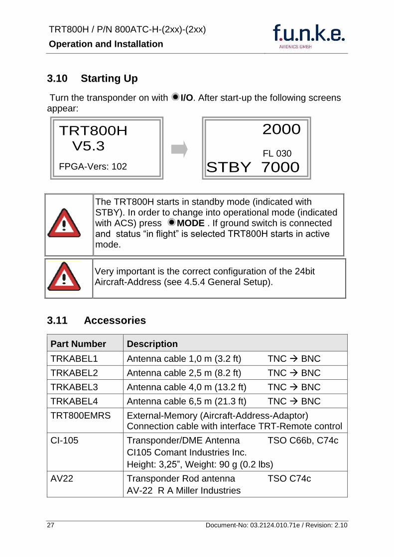
TRT800H PN 800ATC-H-(2xx)-(2xx)
Operation and Installation
28 Document-No 03212401071e Revision 210
312 Drawings
3121 Dimensions
20mm15 mm
170 mm
TRT800TRT800H
65 mm
65
mm
Oslash 57 mm
Static Air
Antenna
PowerRS232
3122 Mounting Advices
Connections Area
8
0 m
m
Panel Cut-out
470 mm
470
mm
575 mm
4 x Oslash 4 mm
Oslash
Connector (plug) has to be clamped with both spring locks
No screws may be turned in more than max 15mm into the device ndash even if no hard limit is noticeable
Fixing clips (spring) left right
TRT800H PN 800ATC-H-(2xx)-(2xx)
Operation and Installation
29 Document-No 03212401071e Revision 210
4 TRANSPONDER SETTINGS
41 Overview
The TRT800H is capable of storing the following information
ICAO 24-Bit Aircraft-Address (AA)
Aircraft Category (AC)
Flight Identification (FID)
Ground-Switch (YesNo)
Speed Category (RI)
RS232 Interface Configuration
All of these data are configurable in the Setup and are stored in the external memory module integrated within the housing of the D-Sub connector (included in the delivery)
The cable with this connector shall remain in the aircraft even if the unit is removed to ensure that the ICAO 24bit aircraft address is fixed to the aircraft
Additionally the following usertransponder related settings are stored transponder internally
Active Squawk
Passive Squawk
VFR Squawk
Altitude offset
Display brightness
42 Display Configuration Summary
Transponder provides the opportunity to show summary of complete current settings To access configuration summary pages push and hold
ID in Standby mode Release ID if ldquoSHOW SETUPrdquo is displayed The summary is subdivided into the following pages
TRT800H PN 800ATC-H-(2xx)-(2xx)
Operation and Installation
30 Document-No 03212401071e Revision 210
Page 1
Aircraft Address
Aircraft Category
Flight Identification
MODE
Page 2 Speed Category
Ground Switch option
Remote Header option
MODE
Page 3 RS-232 Settings
Protocol baud rate position (if available)1
MODE
Page 4 Altitude correction settings
(part 1)
MODE
Page 5 Altitude correction settings
(part 2)
Note 1 Position data will only be displayed if
a GPS protocol is set as interface protocol (NMEA FREEFLIGHT AR-NAV)
18000 ft 0ft 25000 ft + 100ft 35000 ft - 50ft
exit
ALTITUDE CORRECTION 2000 ft 0ft 10000 ft + 100ft next
RS-232 NMEA Baud 4800 Pos 481 99 next
Speed Cat 8 Ground Sw YES Remote Hd NO next
AA F E 1 2 3 4 AC 1 9 FID 4 4 E 1 2 3 next
TRT800H PN 800ATC-H-(2xx)-(2xx)
Operation and Installation
31 Document-No 03212401071e Revision 210
GPS receiver is connected and transmits data (if not ldquoPos no datardquo is displayed)
a valid position is transmitted (if not ldquoPos wrong datardquo is displayed)
While configuration summary page is displayed no new position data will be processed
43 General settings
431 ICAO 24-Bit Aircraft Address (AA)
Ask your national aviation authority (e g in Germany LBA Referat B5 Department ldquoVerkehrszulassungrdquo) how to obtain the AA In the case of aerial sports equipment the contact point would be the respective associations Only the assigned AA has to be used and must not be modified at any time because a duplicate address would jeopardize the data surveillance and integrity figures of Mode S
If no AA is stored after power on the display shows ldquoCRADLE OFFrdquo and the transponder operates in Mode AC
(Configuration of the AA see section 454)
432 Aircraft Category (AC)
Code Description Code Description
11 Emergency Vehicle 1C Ultra-Light Paraglider
12 Service Vehicle 1E Drone
19 Glider 21 Aircraft (D-Exxx) lt 15500 lbs Motor Glider (D-Kxxx)
1A Balloon amp Airship 22 Aircraft ge 15500 lbslt 75000 lbs
1B Paratrooper 27 Rotorcraft
Only one of the Codes mentioned in the table above must be used
Setuprarr454
Setuprarr454
TRT800H PN 800ATC-H-(2xx)-(2xx)
Operation and Installation
32 Document-No 03212401071e Revision 210
433 Flight-ID (FID)
Per ICAO regulation Mode-S data must contain a valid flight identification (FID) to ensure that the correlation between flight plan and radar data will work automatically
FID setting is required to correspond to the aircraft identification that has been specified at item 7 of the ICAO flight plan It contains seven characters at a maximum (left-aligned no additional zeros dashes or spacesblanks)
For an aircraft using a company call sign the Flight-ID mostly consists of the ICAO three-letter designator for the aircraft operator followed by an identification code eg KLM511 BAW213 JTR25
If no company call sign is used or no flight plan is filed the default FID to be set consists of the registration marking of the aircraft (eg DEABC) with no dashes spacesblanks or additional zeros even if they are included in the registration marking on the aircraft (tail number) While entering the FID into the transponder the last remaining digits must be filled with blanks
The ICAO Flight Plan only specifies 7 characters for FID funke AVIONICS reserves 8 characters as stated in ED-73B for further expansion of the flight plan
The user shall only program 7 characters for FID
Setuprarr454
TRT800H PN 800ATC-H-(2xx)-(2xx)
Operation and Installation
33 Document-No 03212401071e Revision 210
434 Reply Information - Speed Category (RI)
Besides AA AC and FID another important part of the Mode-S data is the Speed Category of the respective aircraft This speed category shall be configured in the setup and must contain one of the following codes
Code Description
08 No maximum airspeed data available
09 Maximum airspeed le 75 kt
10 75 kt gt maximum airspeed le 150 kt
11 150 kt gt maximum airspeed le 300 kt
12 300 kt gt maximum airspeed le 600 kt
13 600 kt gt maximum airspeed le 1200 kt
14 Maximum airspeed gt 1200 kt
15 Not assigned
44 Optional settings
441 Option Ground-Switch
If a ground switch is connected (and enabled in setup) the transponder is able to determine on-ground and in-flight state On-ground state is activated automatically once the gear touches the ground On-ground state is indicated on display by symbol G (apart from lsquoFrsquo for In-flight-state)
In On-ground-state the transponder will reply differently to certain addressed interrogations Also the transmission rate of some periodically sent data (squitters ADS-B) is reduced This allows ATC to distinguish between airborne aircraft and those on the ground and it reduces the Mode S channel load
For small aircraft authorities normally do not require such a ground switch In this case the transponder will use the same data formats on the ground as in the airborne state
Setuprarr454 Wiringrarr373
Setuprarr454
TRT800H PN 800ATC-H-(2xx)-(2xx)
Operation and Installation
34 Document-No 03212401071e Revision 210
442 Option Remote Header
The transponder provides a TRT800RT remote control interface If a remote header TRT800RT is connected transponder can be remote controlled via this interface Remote interface provides control of all standard user inputs available during standard operational mode For more information see TRT800RT manual Remote control interface de-activation is setup configurable Remote control interface must only be connected to TRT800RT
443 Serial Interface (RS232)
Using serial interface a GPS receiver can be connected to broadcast own position via ADS-B Out position message Position could be received by other appropriately equipped aircrafts and processed for collision avoidance ADS-B Out functionality
The ADS-B function of this device has not been evaluated during the FAA TSO certification process other than to ensure non-interference Due to the SW assurance of DAL D the ADS-B function cannot be used in the US National Airspace Connecting a GPS source will not comply to FAA certification requirements with regard to ADS-B
Supported formatsprotocols are
Option Description Baud rate
FREEFLIGHT GPSWAAS Sensor 1201
NexNav NNL 3101
19200
AR-NAV Bendix King
KLN 89B KLN 94 ldquoStandard RS232 Sentencerdquo
KMD 150 ldquoSentence Type 1rdquo
Garmin 400 Series ldquoSentence Type 1rdquo (with and without altitude data)
9600
NMEA NMEA-Format data format RMC is expected
4800
Setuprarr454 Wiringrarr373
Setuprarr454 Wiringrarr373
TRT800H PN 800ATC-H-(2xx)-(2xx)
Operation and Installation
35 Document-No 03212401071e Revision 210
Option Description Baud rate
FAVISIA Glass Cockpit support
FAVISIA Data format to be processed in FAVISIA avionics suite
-
FAVISIA+GPS Data format to be processed in FAVISIA avionics suite (output) and additional processing of incoming NMEA GPS-Receiver position data to support the ADS-B Out functionality
4800
Other
Comm-AB-support
Data format for special purpose An additional data link processor allows COMM-AB operation and processing of the position information of a flight management system simultaneously
38400
Disabled No communication via RS232 interface -
444 Altitude CorrectionOffset
The TRT800H has an integrated temperature compensated high-precision pressure sensor This sensor is factory-calibrated so that it will yield accurate flight level (uncorrected pressure altitude) within the entire altitude range
However due to differences in calibration of the TRT800H pressure sensor and the altimeter in the cockpit it may become necessary to adjust the TRT800H pressure readings so that the value indicated and transmitted by the TRT800H corresponds to the indication of the primary altimeter seen by the pilot within 125 feet (as specified in ETSO C88aSAE AS 8003)
Setting for all described GPS-systems
1 2 position messages per 2 sec
Setuprarr455
TRT800H PN 800ATC-H-(2xx)-(2xx)
Operation and Installation
36 Document-No 03212401071e Revision 210
The check for correspondence between the primary altimeter and the TRT800H is usually performed every 24 months as part of the aircrafts altimeter checks
Altitude correction is based on setup configurable offset values at five interpolation points ( 2000 8000 18000 25000 and 35000 ft)The offset value itself is limited to a range from -100 to + 100ft at each point (10ft steps)
45 Setup Procedure
Programming of the ICAOA 24-bit Aircraft Address and of the Aircraft Category shall be executed by qualified personnel only
A wrong Aircraft Address or Flight ID may cause serious problems ATC or with ACASTCAS systems
Pilot and owner are responsible for correctly set transponder data
451 Setup Menu Control
In order to access the functions described in the following paragraphs push and hold ID in Standby mode Release ID if desired counter value menu name is displayed to enter the menu The following menu entries are selectable
Count Displayed Name Function
03 FID FID is displayed
48 CHANGE FID Enter FID setup page
913 SHOW SETUP Enter setup summary listed on different pages (no changes possible)
2528 ENTER SETUP Enter transponder general configuration pages
3134 ALTITUDE CORRECTION
Enter altitude correction menu
TRT800H PN 800ATC-H-(2xx)-(2xx)
Operation and Installation
37 Document-No 03212401071e Revision 210
452 Transponder configurationrecord structure
Aircraft related parts of transponder configuration are stored in one out of eight possible records (record=presetting) Each record contains the following information
Aircraft Address (AA 24bit)
Aircraft category (AC)
Flight identification (FID 6-8 numbersletters)
RS-232 Interface setting (eg GPS protocol)
Ground-Switch setting (Installed YesNo)
Speed category (RI) of the respective aircraft
Remote Header setting (Installed YesNo)
User related settings (eg squawk codes display brightness) are stored once in one global record (transponder internally)
453 Transponder configurationrecord handling
At least one record is stored in external memory Up to 8 records can be additional be applied during setup process
If more than one record is applied the active record must be selected out of a list (determined by FID) during start-up of the transponder
Previously applied records can be deleted again by filling FID with zerorsquos only
454 General Setup
Any menu item can be passed by MODE If no changes are made the original settings will remain stored Modification of one menu item does not impact the others No entries will be deleted
TRT800H PN 800ATC-H-(2xx)-(2xx)
Operation and Installation
38 Document-No 03212401071e Revision 210
Step Display (Example)
1 Start-up Transponder
2 Ensure the transponder-mode is bdquoSTBYldquo If necessary change the mode by pressing MODE
3 Press ID A counter is shown at the upper-right corner Hold ID till ldquoENTER SETUPrdquo is displayed
4 After release of ID the first setup menu is displayed
5 helliphellipselect position (^)
rotary knobchange value
MODE
6 With the rotary knob you can select bdquoyesldquo if a Ground Switch is installed if not select ldquonordquo and proceed with step 7
MODE
Record 1
GND Switch YesNo
next
AA EF123456
AC 18
FID ^BCDEFG
next
AA EF123456
AC 18
FID ABCDEFG
next
ENTER SETUP 26
2000 FL 030
STBY 7000
TRT800H PN 800ATC-H-(2xx)-(2xx)
Operation and Installation
39 Document-No 03212401071e Revision 210
Step Display (Example)
7 At this stage the respective speed category shall be selected by using the rotary knob
MODE
8 At this stage a GPS receiver for ADS-B Out can be selected (Selectable by rotary knob)
MODE
9 At this stage remote interface for communication between TRT800H and remote header can be activated (Selectable by rotary knob)
Remote interface must only be activated if a remote header is connected
MODE
10 With ID further Records can now be created and configured as described in the aforementioned steps At start-up of the transponder one of the defined records with all associated configurations need to be selected
MODE
Records ID=Edit Records
EXIT
Record 1
REMOTE Header YesNo
next
Record 1
GPSINTEXT NMEA
next
Record 1
Speed Cat 08-15
next
TRT800H PN 800ATC-H-(2xx)-(2xx)
Operation and Installation
40 Document-No 03212401071e Revision 210
Step Display (Example)
11 You have now left the configuration mode and are back in normal operation
12 Switch off the transponder
13 Switch on the transponder Your ICAO 24-Bit Aircraft Address is now stored
TRT800H V53
FPGA-Vers 102
2000 FL 030
STBY 7000
TRT800H PN 800ATC-H-(2xx)-(2xx)
Operation and Installation
41 Document-No 03212401071e Revision 210
455 Altitude Correction Setup
Altitude correction setup shall be executed by qualified personnel only
Pilot and owner are responsible for correctly set altitude offset values
The usesetting of altitude correction values is only necessary in exceptional cases (see 444 for details)
Altitude correction is based on five interpolation points ( 2000 10000 18000 25000 and 35000 ft)The offset value at each interpolation point can be adjusted in a range from -100 to + 100ft at each point (10ft steps) Offset values set to zero at each interpolation point deactivates altitude correction (defaultfactory setting)
Step Display (Example)
1 Start-up Transponder
2 Ensure the transponder-mode is bdquoSTBYldquo If necessary change the mode by pressing MODE
3 Press ID A counter is shown at the upper-right corner Hold ID till ldquoALTITUDE OFFSETrdquo is displayed
ALTITUDE OFFSET 33
2000 FL 030
STBY 7000
Descriptionrarr444
TRT800H PN 800ATC-H-(2xx)-(2xx)
Operation and Installation
42 Document-No 03212401071e Revision 210
Step Display (Example)
4 After release of ID the first altitude level + corresponding offset value is displayed
5 Change offset value with rotary knob
MODE
6 (9) Repeat last step for another 4 altitude levels 10000ft 18000ft 25000ft 35000ft
MODE
10 You have now left the configuration mode and are back in normal operation
Switch off the transponder
11 Switch on the transponder New altitude offset values will now be used for altitude calculation
Altitude 10000 ft
Offset 0 ft
nextexit
Altitude 2000 ft
Offset 0 ft
next
TRT800H V53
FPGA-Vers 102
2000 FL 030
STBY 7000
Altitude 2000 ft
Offset 0 ft
next
TRT800H PN 800ATC-H-(2xx)-(2xx)
Operation and Installation
43 Document-No 03212401071e Revision 210
5 APPENDIX
51 Technical Data
Compliance CS-ETSO-2C112a
EASA21O269
FAA TSO-C112c
Applicable Documents CS-ETSO-2C112a
FAA TSO-C112c
EUROCAE ED-73C Class 1 Level 2es
RTCA DO-181D Class 1 Level 2es
EUROCAE ED-26
RTCA DO-160D
RTCA DO-178B Software-Level D
Temperature Ranges
Operation -20 degC to +55 degC for 30 min +70degC
Storage -55 degC to +85 degC
Altitude Range le 35 000 ft
Speed Range le 250 kt (TAS)
Shock 6 G Operation
20 G crash safety
Environmental Categories RTCA DO-160D EnvCat [C1Z]CAA[SM]XXXXXXZBAAA[TT]M[B3F3]XXA
Power Supply 138 VDC (10 VDC 16 VDC)
040 A 138 VDC (typ)
070 A 138 VDC (max)
10 W (max)
TRT800H PN 800ATC-H-(2xx)-(2xx)
Operation and Installation
44 Document-No 03212401071e Revision 210
Fuse External 2A-slow-blow fuse
Mounting Panel cut-out d=575 mm
Weight 06 kg (132 lbs)
Receiver Characteristics
Sensitivity
RF input power level resulting in a 90 reply rate
A MTL for ATCRBS and ATCRBSMode S All-Call interrogations -74 dBm plusmn3 dB
B MTL for Mode S interrogations -74 dBm plusmn 3 dB
Reply transmission frequency
1090 plusmn 1 MHz
RF Peak Power Output 21 dBW (126 W) at antenna base (with maximum cable attenuation of 15 dB)
Squitter (ADS-B) transmitted at random intervals uniformly distributed over the range from 08 to 12 seconds full self-verification of data and occurrence
Mode S Elementary Surveillance
ICAO 24-bit Aircraft Address (Hex-Code)
aircraft address as assigned by national aviation authority
FID Flight ID Flight Plan call sign or aircraft registration marking
Capability Report Reports the available data and means by which the transponder can report
Pressure Altitude Up to 35 000 ft in 25 ft increments
Flight Status in-flight on-ground
Mode S Enhanced Surveillance
Level 2es Comm-A Comm-B 56112-Bit-Messages
SI-capability
TRT800H PN 800ATC-H-(2xx)-(2xx)
Operation and Installation
45 Document-No 03212401071e Revision 210
52 Environmental Conditions
Characteristic DOndash160D Section Cat Condition
Temperature Altitude 40
C1
Low ground survival temperature
451 ndash 55degC
Low operating temperature 451 ndash 20degC
High ground survival Temperature
452 + 85degC
High Short-time Operating Temperature
452 + 70degC
High Operating Temperature 453 + 55degC
In-Flight Loss of Cooling 454 Z No auxiliary cooling required
Altitude 461 C1 35 000 ft
Temperature Variation 50 C 2degC change rate minimum per minute
Humidity 60 A
Shock 70 A
6 G operational shocks
20 G Crash Safety
Test Type R in all 6 directions
Vibration 80 S Vibration Curve M
Explosion Proofness 90 X No test required
Water Proofness 100 X No test required
Fluids Susceptibilities 110 X No test required
Sand and Dust 120 X No test required
Fungus Resistance 130 X No test required
Salt Spray 140 X No test required
Magnetic Effect 150 Z Less than 03 m
Power Input (DC) 160 B
Voltage Spike Conducted 170 A
Audio Frequency Conducted Susceptibility
180 A
TRT800H PN 800ATC-H-(2xx)-(2xx)
Operation and Installation
46 Document-No 03212401071e Revision 210
Characteristic DOndash160D Section Cat Condition
Induced Signal Susceptibility 190 A
Radio Frequency Susceptibility
200 TT
Emission of RF Energy 210 M
Lightning Induced Transient Susceptibility
220 B3F3
Lightning Direct Effects 230 X No test required
Icing 240 X No test required
Electrostatic Discharge (ESD) 250 A
53 DO-178B Open Problem Reports
There are no open problem reports for the software of this device
TRT800H PN 800ATC-H-(2xx)-(2xx)
Operation and Installation
47 Document-No 03212401071e Revision 210
Notes
f funke funke means ndash fabrication utilities network know-how engineering
funke AVIONICS GmbH Heinz-Strachowitz-Str 4
DE-86807 Buchloe Germany
phone +49-8241 80066 0
fax +49-8241 80066 99 E-mail
servicefunkeavionicsde wwwfunkeavionicsde
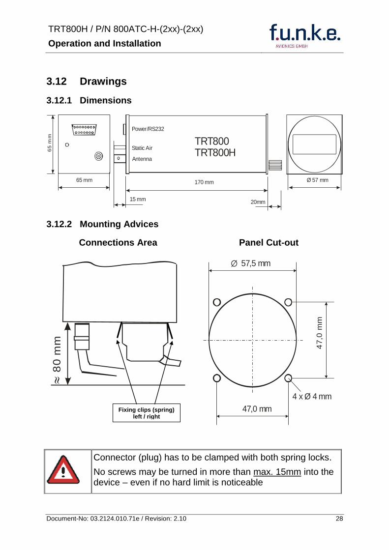
TRT800H PN 800ATC-H-(2xx)-(2xx)
Operation and Installation
29 Document-No 03212401071e Revision 210
4 TRANSPONDER SETTINGS
41 Overview
The TRT800H is capable of storing the following information
ICAO 24-Bit Aircraft-Address (AA)
Aircraft Category (AC)
Flight Identification (FID)
Ground-Switch (YesNo)
Speed Category (RI)
RS232 Interface Configuration
All of these data are configurable in the Setup and are stored in the external memory module integrated within the housing of the D-Sub connector (included in the delivery)
The cable with this connector shall remain in the aircraft even if the unit is removed to ensure that the ICAO 24bit aircraft address is fixed to the aircraft
Additionally the following usertransponder related settings are stored transponder internally
Active Squawk
Passive Squawk
VFR Squawk
Altitude offset
Display brightness
42 Display Configuration Summary
Transponder provides the opportunity to show summary of complete current settings To access configuration summary pages push and hold
ID in Standby mode Release ID if ldquoSHOW SETUPrdquo is displayed The summary is subdivided into the following pages
TRT800H PN 800ATC-H-(2xx)-(2xx)
Operation and Installation
30 Document-No 03212401071e Revision 210
Page 1
Aircraft Address
Aircraft Category
Flight Identification
MODE
Page 2 Speed Category
Ground Switch option
Remote Header option
MODE
Page 3 RS-232 Settings
Protocol baud rate position (if available)1
MODE
Page 4 Altitude correction settings
(part 1)
MODE
Page 5 Altitude correction settings
(part 2)
Note 1 Position data will only be displayed if
a GPS protocol is set as interface protocol (NMEA FREEFLIGHT AR-NAV)
18000 ft 0ft 25000 ft + 100ft 35000 ft - 50ft
exit
ALTITUDE CORRECTION 2000 ft 0ft 10000 ft + 100ft next
RS-232 NMEA Baud 4800 Pos 481 99 next
Speed Cat 8 Ground Sw YES Remote Hd NO next
AA F E 1 2 3 4 AC 1 9 FID 4 4 E 1 2 3 next
TRT800H PN 800ATC-H-(2xx)-(2xx)
Operation and Installation
31 Document-No 03212401071e Revision 210
GPS receiver is connected and transmits data (if not ldquoPos no datardquo is displayed)
a valid position is transmitted (if not ldquoPos wrong datardquo is displayed)
While configuration summary page is displayed no new position data will be processed
43 General settings
431 ICAO 24-Bit Aircraft Address (AA)
Ask your national aviation authority (e g in Germany LBA Referat B5 Department ldquoVerkehrszulassungrdquo) how to obtain the AA In the case of aerial sports equipment the contact point would be the respective associations Only the assigned AA has to be used and must not be modified at any time because a duplicate address would jeopardize the data surveillance and integrity figures of Mode S
If no AA is stored after power on the display shows ldquoCRADLE OFFrdquo and the transponder operates in Mode AC
(Configuration of the AA see section 454)
432 Aircraft Category (AC)
Code Description Code Description
11 Emergency Vehicle 1C Ultra-Light Paraglider
12 Service Vehicle 1E Drone
19 Glider 21 Aircraft (D-Exxx) lt 15500 lbs Motor Glider (D-Kxxx)
1A Balloon amp Airship 22 Aircraft ge 15500 lbslt 75000 lbs
1B Paratrooper 27 Rotorcraft
Only one of the Codes mentioned in the table above must be used
Setuprarr454
Setuprarr454
TRT800H PN 800ATC-H-(2xx)-(2xx)
Operation and Installation
32 Document-No 03212401071e Revision 210
433 Flight-ID (FID)
Per ICAO regulation Mode-S data must contain a valid flight identification (FID) to ensure that the correlation between flight plan and radar data will work automatically
FID setting is required to correspond to the aircraft identification that has been specified at item 7 of the ICAO flight plan It contains seven characters at a maximum (left-aligned no additional zeros dashes or spacesblanks)
For an aircraft using a company call sign the Flight-ID mostly consists of the ICAO three-letter designator for the aircraft operator followed by an identification code eg KLM511 BAW213 JTR25
If no company call sign is used or no flight plan is filed the default FID to be set consists of the registration marking of the aircraft (eg DEABC) with no dashes spacesblanks or additional zeros even if they are included in the registration marking on the aircraft (tail number) While entering the FID into the transponder the last remaining digits must be filled with blanks
The ICAO Flight Plan only specifies 7 characters for FID funke AVIONICS reserves 8 characters as stated in ED-73B for further expansion of the flight plan
The user shall only program 7 characters for FID
Setuprarr454
TRT800H PN 800ATC-H-(2xx)-(2xx)
Operation and Installation
33 Document-No 03212401071e Revision 210
434 Reply Information - Speed Category (RI)
Besides AA AC and FID another important part of the Mode-S data is the Speed Category of the respective aircraft This speed category shall be configured in the setup and must contain one of the following codes
Code Description
08 No maximum airspeed data available
09 Maximum airspeed le 75 kt
10 75 kt gt maximum airspeed le 150 kt
11 150 kt gt maximum airspeed le 300 kt
12 300 kt gt maximum airspeed le 600 kt
13 600 kt gt maximum airspeed le 1200 kt
14 Maximum airspeed gt 1200 kt
15 Not assigned
44 Optional settings
441 Option Ground-Switch
If a ground switch is connected (and enabled in setup) the transponder is able to determine on-ground and in-flight state On-ground state is activated automatically once the gear touches the ground On-ground state is indicated on display by symbol G (apart from lsquoFrsquo for In-flight-state)
In On-ground-state the transponder will reply differently to certain addressed interrogations Also the transmission rate of some periodically sent data (squitters ADS-B) is reduced This allows ATC to distinguish between airborne aircraft and those on the ground and it reduces the Mode S channel load
For small aircraft authorities normally do not require such a ground switch In this case the transponder will use the same data formats on the ground as in the airborne state
Setuprarr454 Wiringrarr373
Setuprarr454
TRT800H PN 800ATC-H-(2xx)-(2xx)
Operation and Installation
34 Document-No 03212401071e Revision 210
442 Option Remote Header
The transponder provides a TRT800RT remote control interface If a remote header TRT800RT is connected transponder can be remote controlled via this interface Remote interface provides control of all standard user inputs available during standard operational mode For more information see TRT800RT manual Remote control interface de-activation is setup configurable Remote control interface must only be connected to TRT800RT
443 Serial Interface (RS232)
Using serial interface a GPS receiver can be connected to broadcast own position via ADS-B Out position message Position could be received by other appropriately equipped aircrafts and processed for collision avoidance ADS-B Out functionality
The ADS-B function of this device has not been evaluated during the FAA TSO certification process other than to ensure non-interference Due to the SW assurance of DAL D the ADS-B function cannot be used in the US National Airspace Connecting a GPS source will not comply to FAA certification requirements with regard to ADS-B
Supported formatsprotocols are
Option Description Baud rate
FREEFLIGHT GPSWAAS Sensor 1201
NexNav NNL 3101
19200
AR-NAV Bendix King
KLN 89B KLN 94 ldquoStandard RS232 Sentencerdquo
KMD 150 ldquoSentence Type 1rdquo
Garmin 400 Series ldquoSentence Type 1rdquo (with and without altitude data)
9600
NMEA NMEA-Format data format RMC is expected
4800
Setuprarr454 Wiringrarr373
Setuprarr454 Wiringrarr373
TRT800H PN 800ATC-H-(2xx)-(2xx)
Operation and Installation
35 Document-No 03212401071e Revision 210
Option Description Baud rate
FAVISIA Glass Cockpit support
FAVISIA Data format to be processed in FAVISIA avionics suite
-
FAVISIA+GPS Data format to be processed in FAVISIA avionics suite (output) and additional processing of incoming NMEA GPS-Receiver position data to support the ADS-B Out functionality
4800
Other
Comm-AB-support
Data format for special purpose An additional data link processor allows COMM-AB operation and processing of the position information of a flight management system simultaneously
38400
Disabled No communication via RS232 interface -
444 Altitude CorrectionOffset
The TRT800H has an integrated temperature compensated high-precision pressure sensor This sensor is factory-calibrated so that it will yield accurate flight level (uncorrected pressure altitude) within the entire altitude range
However due to differences in calibration of the TRT800H pressure sensor and the altimeter in the cockpit it may become necessary to adjust the TRT800H pressure readings so that the value indicated and transmitted by the TRT800H corresponds to the indication of the primary altimeter seen by the pilot within 125 feet (as specified in ETSO C88aSAE AS 8003)
Setting for all described GPS-systems
1 2 position messages per 2 sec
Setuprarr455
TRT800H PN 800ATC-H-(2xx)-(2xx)
Operation and Installation
36 Document-No 03212401071e Revision 210
The check for correspondence between the primary altimeter and the TRT800H is usually performed every 24 months as part of the aircrafts altimeter checks
Altitude correction is based on setup configurable offset values at five interpolation points ( 2000 8000 18000 25000 and 35000 ft)The offset value itself is limited to a range from -100 to + 100ft at each point (10ft steps)
45 Setup Procedure
Programming of the ICAOA 24-bit Aircraft Address and of the Aircraft Category shall be executed by qualified personnel only
A wrong Aircraft Address or Flight ID may cause serious problems ATC or with ACASTCAS systems
Pilot and owner are responsible for correctly set transponder data
451 Setup Menu Control
In order to access the functions described in the following paragraphs push and hold ID in Standby mode Release ID if desired counter value menu name is displayed to enter the menu The following menu entries are selectable
Count Displayed Name Function
03 FID FID is displayed
48 CHANGE FID Enter FID setup page
913 SHOW SETUP Enter setup summary listed on different pages (no changes possible)
2528 ENTER SETUP Enter transponder general configuration pages
3134 ALTITUDE CORRECTION
Enter altitude correction menu
TRT800H PN 800ATC-H-(2xx)-(2xx)
Operation and Installation
37 Document-No 03212401071e Revision 210
452 Transponder configurationrecord structure
Aircraft related parts of transponder configuration are stored in one out of eight possible records (record=presetting) Each record contains the following information
Aircraft Address (AA 24bit)
Aircraft category (AC)
Flight identification (FID 6-8 numbersletters)
RS-232 Interface setting (eg GPS protocol)
Ground-Switch setting (Installed YesNo)
Speed category (RI) of the respective aircraft
Remote Header setting (Installed YesNo)
User related settings (eg squawk codes display brightness) are stored once in one global record (transponder internally)
453 Transponder configurationrecord handling
At least one record is stored in external memory Up to 8 records can be additional be applied during setup process
If more than one record is applied the active record must be selected out of a list (determined by FID) during start-up of the transponder
Previously applied records can be deleted again by filling FID with zerorsquos only
454 General Setup
Any menu item can be passed by MODE If no changes are made the original settings will remain stored Modification of one menu item does not impact the others No entries will be deleted
TRT800H PN 800ATC-H-(2xx)-(2xx)
Operation and Installation
38 Document-No 03212401071e Revision 210
Step Display (Example)
1 Start-up Transponder
2 Ensure the transponder-mode is bdquoSTBYldquo If necessary change the mode by pressing MODE
3 Press ID A counter is shown at the upper-right corner Hold ID till ldquoENTER SETUPrdquo is displayed
4 After release of ID the first setup menu is displayed
5 helliphellipselect position (^)
rotary knobchange value
MODE
6 With the rotary knob you can select bdquoyesldquo if a Ground Switch is installed if not select ldquonordquo and proceed with step 7
MODE
Record 1
GND Switch YesNo
next
AA EF123456
AC 18
FID ^BCDEFG
next
AA EF123456
AC 18
FID ABCDEFG
next
ENTER SETUP 26
2000 FL 030
STBY 7000
TRT800H PN 800ATC-H-(2xx)-(2xx)
Operation and Installation
39 Document-No 03212401071e Revision 210
Step Display (Example)
7 At this stage the respective speed category shall be selected by using the rotary knob
MODE
8 At this stage a GPS receiver for ADS-B Out can be selected (Selectable by rotary knob)
MODE
9 At this stage remote interface for communication between TRT800H and remote header can be activated (Selectable by rotary knob)
Remote interface must only be activated if a remote header is connected
MODE
10 With ID further Records can now be created and configured as described in the aforementioned steps At start-up of the transponder one of the defined records with all associated configurations need to be selected
MODE
Records ID=Edit Records
EXIT
Record 1
REMOTE Header YesNo
next
Record 1
GPSINTEXT NMEA
next
Record 1
Speed Cat 08-15
next
TRT800H PN 800ATC-H-(2xx)-(2xx)
Operation and Installation
40 Document-No 03212401071e Revision 210
Step Display (Example)
11 You have now left the configuration mode and are back in normal operation
12 Switch off the transponder
13 Switch on the transponder Your ICAO 24-Bit Aircraft Address is now stored
TRT800H V53
FPGA-Vers 102
2000 FL 030
STBY 7000
TRT800H PN 800ATC-H-(2xx)-(2xx)
Operation and Installation
41 Document-No 03212401071e Revision 210
455 Altitude Correction Setup
Altitude correction setup shall be executed by qualified personnel only
Pilot and owner are responsible for correctly set altitude offset values
The usesetting of altitude correction values is only necessary in exceptional cases (see 444 for details)
Altitude correction is based on five interpolation points ( 2000 10000 18000 25000 and 35000 ft)The offset value at each interpolation point can be adjusted in a range from -100 to + 100ft at each point (10ft steps) Offset values set to zero at each interpolation point deactivates altitude correction (defaultfactory setting)
Step Display (Example)
1 Start-up Transponder
2 Ensure the transponder-mode is bdquoSTBYldquo If necessary change the mode by pressing MODE
3 Press ID A counter is shown at the upper-right corner Hold ID till ldquoALTITUDE OFFSETrdquo is displayed
ALTITUDE OFFSET 33
2000 FL 030
STBY 7000
Descriptionrarr444
TRT800H PN 800ATC-H-(2xx)-(2xx)
Operation and Installation
42 Document-No 03212401071e Revision 210
Step Display (Example)
4 After release of ID the first altitude level + corresponding offset value is displayed
5 Change offset value with rotary knob
MODE
6 (9) Repeat last step for another 4 altitude levels 10000ft 18000ft 25000ft 35000ft
MODE
10 You have now left the configuration mode and are back in normal operation
Switch off the transponder
11 Switch on the transponder New altitude offset values will now be used for altitude calculation
Altitude 10000 ft
Offset 0 ft
nextexit
Altitude 2000 ft
Offset 0 ft
next
TRT800H V53
FPGA-Vers 102
2000 FL 030
STBY 7000
Altitude 2000 ft
Offset 0 ft
next
TRT800H PN 800ATC-H-(2xx)-(2xx)
Operation and Installation
43 Document-No 03212401071e Revision 210
5 APPENDIX
51 Technical Data
Compliance CS-ETSO-2C112a
EASA21O269
FAA TSO-C112c
Applicable Documents CS-ETSO-2C112a
FAA TSO-C112c
EUROCAE ED-73C Class 1 Level 2es
RTCA DO-181D Class 1 Level 2es
EUROCAE ED-26
RTCA DO-160D
RTCA DO-178B Software-Level D
Temperature Ranges
Operation -20 degC to +55 degC for 30 min +70degC
Storage -55 degC to +85 degC
Altitude Range le 35 000 ft
Speed Range le 250 kt (TAS)
Shock 6 G Operation
20 G crash safety
Environmental Categories RTCA DO-160D EnvCat [C1Z]CAA[SM]XXXXXXZBAAA[TT]M[B3F3]XXA
Power Supply 138 VDC (10 VDC 16 VDC)
040 A 138 VDC (typ)
070 A 138 VDC (max)
10 W (max)
TRT800H PN 800ATC-H-(2xx)-(2xx)
Operation and Installation
44 Document-No 03212401071e Revision 210
Fuse External 2A-slow-blow fuse
Mounting Panel cut-out d=575 mm
Weight 06 kg (132 lbs)
Receiver Characteristics
Sensitivity
RF input power level resulting in a 90 reply rate
A MTL for ATCRBS and ATCRBSMode S All-Call interrogations -74 dBm plusmn3 dB
B MTL for Mode S interrogations -74 dBm plusmn 3 dB
Reply transmission frequency
1090 plusmn 1 MHz
RF Peak Power Output 21 dBW (126 W) at antenna base (with maximum cable attenuation of 15 dB)
Squitter (ADS-B) transmitted at random intervals uniformly distributed over the range from 08 to 12 seconds full self-verification of data and occurrence
Mode S Elementary Surveillance
ICAO 24-bit Aircraft Address (Hex-Code)
aircraft address as assigned by national aviation authority
FID Flight ID Flight Plan call sign or aircraft registration marking
Capability Report Reports the available data and means by which the transponder can report
Pressure Altitude Up to 35 000 ft in 25 ft increments
Flight Status in-flight on-ground
Mode S Enhanced Surveillance
Level 2es Comm-A Comm-B 56112-Bit-Messages
SI-capability
TRT800H PN 800ATC-H-(2xx)-(2xx)
Operation and Installation
45 Document-No 03212401071e Revision 210
52 Environmental Conditions
Characteristic DOndash160D Section Cat Condition
Temperature Altitude 40
C1
Low ground survival temperature
451 ndash 55degC
Low operating temperature 451 ndash 20degC
High ground survival Temperature
452 + 85degC
High Short-time Operating Temperature
452 + 70degC
High Operating Temperature 453 + 55degC
In-Flight Loss of Cooling 454 Z No auxiliary cooling required
Altitude 461 C1 35 000 ft
Temperature Variation 50 C 2degC change rate minimum per minute
Humidity 60 A
Shock 70 A
6 G operational shocks
20 G Crash Safety
Test Type R in all 6 directions
Vibration 80 S Vibration Curve M
Explosion Proofness 90 X No test required
Water Proofness 100 X No test required
Fluids Susceptibilities 110 X No test required
Sand and Dust 120 X No test required
Fungus Resistance 130 X No test required
Salt Spray 140 X No test required
Magnetic Effect 150 Z Less than 03 m
Power Input (DC) 160 B
Voltage Spike Conducted 170 A
Audio Frequency Conducted Susceptibility
180 A
TRT800H PN 800ATC-H-(2xx)-(2xx)
Operation and Installation
46 Document-No 03212401071e Revision 210
Characteristic DOndash160D Section Cat Condition
Induced Signal Susceptibility 190 A
Radio Frequency Susceptibility
200 TT
Emission of RF Energy 210 M
Lightning Induced Transient Susceptibility
220 B3F3
Lightning Direct Effects 230 X No test required
Icing 240 X No test required
Electrostatic Discharge (ESD) 250 A
53 DO-178B Open Problem Reports
There are no open problem reports for the software of this device
TRT800H PN 800ATC-H-(2xx)-(2xx)
Operation and Installation
47 Document-No 03212401071e Revision 210
Notes
f funke funke means ndash fabrication utilities network know-how engineering
funke AVIONICS GmbH Heinz-Strachowitz-Str 4
DE-86807 Buchloe Germany
phone +49-8241 80066 0
fax +49-8241 80066 99 E-mail
servicefunkeavionicsde wwwfunkeavionicsde
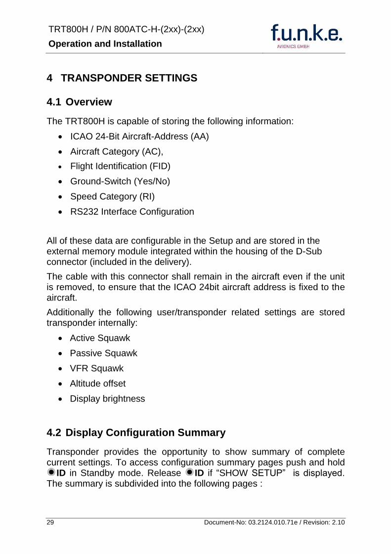
TRT800H PN 800ATC-H-(2xx)-(2xx)
Operation and Installation
30 Document-No 03212401071e Revision 210
Page 1
Aircraft Address
Aircraft Category
Flight Identification
MODE
Page 2 Speed Category
Ground Switch option
Remote Header option
MODE
Page 3 RS-232 Settings
Protocol baud rate position (if available)1
MODE
Page 4 Altitude correction settings
(part 1)
MODE
Page 5 Altitude correction settings
(part 2)
Note 1 Position data will only be displayed if
a GPS protocol is set as interface protocol (NMEA FREEFLIGHT AR-NAV)
18000 ft 0ft 25000 ft + 100ft 35000 ft - 50ft
exit
ALTITUDE CORRECTION 2000 ft 0ft 10000 ft + 100ft next
RS-232 NMEA Baud 4800 Pos 481 99 next
Speed Cat 8 Ground Sw YES Remote Hd NO next
AA F E 1 2 3 4 AC 1 9 FID 4 4 E 1 2 3 next
TRT800H PN 800ATC-H-(2xx)-(2xx)
Operation and Installation
31 Document-No 03212401071e Revision 210
GPS receiver is connected and transmits data (if not ldquoPos no datardquo is displayed)
a valid position is transmitted (if not ldquoPos wrong datardquo is displayed)
While configuration summary page is displayed no new position data will be processed
43 General settings
431 ICAO 24-Bit Aircraft Address (AA)
Ask your national aviation authority (e g in Germany LBA Referat B5 Department ldquoVerkehrszulassungrdquo) how to obtain the AA In the case of aerial sports equipment the contact point would be the respective associations Only the assigned AA has to be used and must not be modified at any time because a duplicate address would jeopardize the data surveillance and integrity figures of Mode S
If no AA is stored after power on the display shows ldquoCRADLE OFFrdquo and the transponder operates in Mode AC
(Configuration of the AA see section 454)
432 Aircraft Category (AC)
Code Description Code Description
11 Emergency Vehicle 1C Ultra-Light Paraglider
12 Service Vehicle 1E Drone
19 Glider 21 Aircraft (D-Exxx) lt 15500 lbs Motor Glider (D-Kxxx)
1A Balloon amp Airship 22 Aircraft ge 15500 lbslt 75000 lbs
1B Paratrooper 27 Rotorcraft
Only one of the Codes mentioned in the table above must be used
Setuprarr454
Setuprarr454
TRT800H PN 800ATC-H-(2xx)-(2xx)
Operation and Installation
32 Document-No 03212401071e Revision 210
433 Flight-ID (FID)
Per ICAO regulation Mode-S data must contain a valid flight identification (FID) to ensure that the correlation between flight plan and radar data will work automatically
FID setting is required to correspond to the aircraft identification that has been specified at item 7 of the ICAO flight plan It contains seven characters at a maximum (left-aligned no additional zeros dashes or spacesblanks)
For an aircraft using a company call sign the Flight-ID mostly consists of the ICAO three-letter designator for the aircraft operator followed by an identification code eg KLM511 BAW213 JTR25
If no company call sign is used or no flight plan is filed the default FID to be set consists of the registration marking of the aircraft (eg DEABC) with no dashes spacesblanks or additional zeros even if they are included in the registration marking on the aircraft (tail number) While entering the FID into the transponder the last remaining digits must be filled with blanks
The ICAO Flight Plan only specifies 7 characters for FID funke AVIONICS reserves 8 characters as stated in ED-73B for further expansion of the flight plan
The user shall only program 7 characters for FID
Setuprarr454
TRT800H PN 800ATC-H-(2xx)-(2xx)
Operation and Installation
33 Document-No 03212401071e Revision 210
434 Reply Information - Speed Category (RI)
Besides AA AC and FID another important part of the Mode-S data is the Speed Category of the respective aircraft This speed category shall be configured in the setup and must contain one of the following codes
Code Description
08 No maximum airspeed data available
09 Maximum airspeed le 75 kt
10 75 kt gt maximum airspeed le 150 kt
11 150 kt gt maximum airspeed le 300 kt
12 300 kt gt maximum airspeed le 600 kt
13 600 kt gt maximum airspeed le 1200 kt
14 Maximum airspeed gt 1200 kt
15 Not assigned
44 Optional settings
441 Option Ground-Switch
If a ground switch is connected (and enabled in setup) the transponder is able to determine on-ground and in-flight state On-ground state is activated automatically once the gear touches the ground On-ground state is indicated on display by symbol G (apart from lsquoFrsquo for In-flight-state)
In On-ground-state the transponder will reply differently to certain addressed interrogations Also the transmission rate of some periodically sent data (squitters ADS-B) is reduced This allows ATC to distinguish between airborne aircraft and those on the ground and it reduces the Mode S channel load
For small aircraft authorities normally do not require such a ground switch In this case the transponder will use the same data formats on the ground as in the airborne state
Setuprarr454 Wiringrarr373
Setuprarr454
TRT800H PN 800ATC-H-(2xx)-(2xx)
Operation and Installation
34 Document-No 03212401071e Revision 210
442 Option Remote Header
The transponder provides a TRT800RT remote control interface If a remote header TRT800RT is connected transponder can be remote controlled via this interface Remote interface provides control of all standard user inputs available during standard operational mode For more information see TRT800RT manual Remote control interface de-activation is setup configurable Remote control interface must only be connected to TRT800RT
443 Serial Interface (RS232)
Using serial interface a GPS receiver can be connected to broadcast own position via ADS-B Out position message Position could be received by other appropriately equipped aircrafts and processed for collision avoidance ADS-B Out functionality
The ADS-B function of this device has not been evaluated during the FAA TSO certification process other than to ensure non-interference Due to the SW assurance of DAL D the ADS-B function cannot be used in the US National Airspace Connecting a GPS source will not comply to FAA certification requirements with regard to ADS-B
Supported formatsprotocols are
Option Description Baud rate
FREEFLIGHT GPSWAAS Sensor 1201
NexNav NNL 3101
19200
AR-NAV Bendix King
KLN 89B KLN 94 ldquoStandard RS232 Sentencerdquo
KMD 150 ldquoSentence Type 1rdquo
Garmin 400 Series ldquoSentence Type 1rdquo (with and without altitude data)
9600
NMEA NMEA-Format data format RMC is expected
4800
Setuprarr454 Wiringrarr373
Setuprarr454 Wiringrarr373
TRT800H PN 800ATC-H-(2xx)-(2xx)
Operation and Installation
35 Document-No 03212401071e Revision 210
Option Description Baud rate
FAVISIA Glass Cockpit support
FAVISIA Data format to be processed in FAVISIA avionics suite
-
FAVISIA+GPS Data format to be processed in FAVISIA avionics suite (output) and additional processing of incoming NMEA GPS-Receiver position data to support the ADS-B Out functionality
4800
Other
Comm-AB-support
Data format for special purpose An additional data link processor allows COMM-AB operation and processing of the position information of a flight management system simultaneously
38400
Disabled No communication via RS232 interface -
444 Altitude CorrectionOffset
The TRT800H has an integrated temperature compensated high-precision pressure sensor This sensor is factory-calibrated so that it will yield accurate flight level (uncorrected pressure altitude) within the entire altitude range
However due to differences in calibration of the TRT800H pressure sensor and the altimeter in the cockpit it may become necessary to adjust the TRT800H pressure readings so that the value indicated and transmitted by the TRT800H corresponds to the indication of the primary altimeter seen by the pilot within 125 feet (as specified in ETSO C88aSAE AS 8003)
Setting for all described GPS-systems
1 2 position messages per 2 sec
Setuprarr455
TRT800H PN 800ATC-H-(2xx)-(2xx)
Operation and Installation
36 Document-No 03212401071e Revision 210
The check for correspondence between the primary altimeter and the TRT800H is usually performed every 24 months as part of the aircrafts altimeter checks
Altitude correction is based on setup configurable offset values at five interpolation points ( 2000 8000 18000 25000 and 35000 ft)The offset value itself is limited to a range from -100 to + 100ft at each point (10ft steps)
45 Setup Procedure
Programming of the ICAOA 24-bit Aircraft Address and of the Aircraft Category shall be executed by qualified personnel only
A wrong Aircraft Address or Flight ID may cause serious problems ATC or with ACASTCAS systems
Pilot and owner are responsible for correctly set transponder data
451 Setup Menu Control
In order to access the functions described in the following paragraphs push and hold ID in Standby mode Release ID if desired counter value menu name is displayed to enter the menu The following menu entries are selectable
Count Displayed Name Function
03 FID FID is displayed
48 CHANGE FID Enter FID setup page
913 SHOW SETUP Enter setup summary listed on different pages (no changes possible)
2528 ENTER SETUP Enter transponder general configuration pages
3134 ALTITUDE CORRECTION
Enter altitude correction menu
TRT800H PN 800ATC-H-(2xx)-(2xx)
Operation and Installation
37 Document-No 03212401071e Revision 210
452 Transponder configurationrecord structure
Aircraft related parts of transponder configuration are stored in one out of eight possible records (record=presetting) Each record contains the following information
Aircraft Address (AA 24bit)
Aircraft category (AC)
Flight identification (FID 6-8 numbersletters)
RS-232 Interface setting (eg GPS protocol)
Ground-Switch setting (Installed YesNo)
Speed category (RI) of the respective aircraft
Remote Header setting (Installed YesNo)
User related settings (eg squawk codes display brightness) are stored once in one global record (transponder internally)
453 Transponder configurationrecord handling
At least one record is stored in external memory Up to 8 records can be additional be applied during setup process
If more than one record is applied the active record must be selected out of a list (determined by FID) during start-up of the transponder
Previously applied records can be deleted again by filling FID with zerorsquos only
454 General Setup
Any menu item can be passed by MODE If no changes are made the original settings will remain stored Modification of one menu item does not impact the others No entries will be deleted
TRT800H PN 800ATC-H-(2xx)-(2xx)
Operation and Installation
38 Document-No 03212401071e Revision 210
Step Display (Example)
1 Start-up Transponder
2 Ensure the transponder-mode is bdquoSTBYldquo If necessary change the mode by pressing MODE
3 Press ID A counter is shown at the upper-right corner Hold ID till ldquoENTER SETUPrdquo is displayed
4 After release of ID the first setup menu is displayed
5 helliphellipselect position (^)
rotary knobchange value
MODE
6 With the rotary knob you can select bdquoyesldquo if a Ground Switch is installed if not select ldquonordquo and proceed with step 7
MODE
Record 1
GND Switch YesNo
next
AA EF123456
AC 18
FID ^BCDEFG
next
AA EF123456
AC 18
FID ABCDEFG
next
ENTER SETUP 26
2000 FL 030
STBY 7000
TRT800H PN 800ATC-H-(2xx)-(2xx)
Operation and Installation
39 Document-No 03212401071e Revision 210
Step Display (Example)
7 At this stage the respective speed category shall be selected by using the rotary knob
MODE
8 At this stage a GPS receiver for ADS-B Out can be selected (Selectable by rotary knob)
MODE
9 At this stage remote interface for communication between TRT800H and remote header can be activated (Selectable by rotary knob)
Remote interface must only be activated if a remote header is connected
MODE
10 With ID further Records can now be created and configured as described in the aforementioned steps At start-up of the transponder one of the defined records with all associated configurations need to be selected
MODE
Records ID=Edit Records
EXIT
Record 1
REMOTE Header YesNo
next
Record 1
GPSINTEXT NMEA
next
Record 1
Speed Cat 08-15
next
TRT800H PN 800ATC-H-(2xx)-(2xx)
Operation and Installation
40 Document-No 03212401071e Revision 210
Step Display (Example)
11 You have now left the configuration mode and are back in normal operation
12 Switch off the transponder
13 Switch on the transponder Your ICAO 24-Bit Aircraft Address is now stored
TRT800H V53
FPGA-Vers 102
2000 FL 030
STBY 7000
TRT800H PN 800ATC-H-(2xx)-(2xx)
Operation and Installation
41 Document-No 03212401071e Revision 210
455 Altitude Correction Setup
Altitude correction setup shall be executed by qualified personnel only
Pilot and owner are responsible for correctly set altitude offset values
The usesetting of altitude correction values is only necessary in exceptional cases (see 444 for details)
Altitude correction is based on five interpolation points ( 2000 10000 18000 25000 and 35000 ft)The offset value at each interpolation point can be adjusted in a range from -100 to + 100ft at each point (10ft steps) Offset values set to zero at each interpolation point deactivates altitude correction (defaultfactory setting)
Step Display (Example)
1 Start-up Transponder
2 Ensure the transponder-mode is bdquoSTBYldquo If necessary change the mode by pressing MODE
3 Press ID A counter is shown at the upper-right corner Hold ID till ldquoALTITUDE OFFSETrdquo is displayed
ALTITUDE OFFSET 33
2000 FL 030
STBY 7000
Descriptionrarr444
TRT800H PN 800ATC-H-(2xx)-(2xx)
Operation and Installation
42 Document-No 03212401071e Revision 210
Step Display (Example)
4 After release of ID the first altitude level + corresponding offset value is displayed
5 Change offset value with rotary knob
MODE
6 (9) Repeat last step for another 4 altitude levels 10000ft 18000ft 25000ft 35000ft
MODE
10 You have now left the configuration mode and are back in normal operation
Switch off the transponder
11 Switch on the transponder New altitude offset values will now be used for altitude calculation
Altitude 10000 ft
Offset 0 ft
nextexit
Altitude 2000 ft
Offset 0 ft
next
TRT800H V53
FPGA-Vers 102
2000 FL 030
STBY 7000
Altitude 2000 ft
Offset 0 ft
next
TRT800H PN 800ATC-H-(2xx)-(2xx)
Operation and Installation
43 Document-No 03212401071e Revision 210
5 APPENDIX
51 Technical Data
Compliance CS-ETSO-2C112a
EASA21O269
FAA TSO-C112c
Applicable Documents CS-ETSO-2C112a
FAA TSO-C112c
EUROCAE ED-73C Class 1 Level 2es
RTCA DO-181D Class 1 Level 2es
EUROCAE ED-26
RTCA DO-160D
RTCA DO-178B Software-Level D
Temperature Ranges
Operation -20 degC to +55 degC for 30 min +70degC
Storage -55 degC to +85 degC
Altitude Range le 35 000 ft
Speed Range le 250 kt (TAS)
Shock 6 G Operation
20 G crash safety
Environmental Categories RTCA DO-160D EnvCat [C1Z]CAA[SM]XXXXXXZBAAA[TT]M[B3F3]XXA
Power Supply 138 VDC (10 VDC 16 VDC)
040 A 138 VDC (typ)
070 A 138 VDC (max)
10 W (max)
TRT800H PN 800ATC-H-(2xx)-(2xx)
Operation and Installation
44 Document-No 03212401071e Revision 210
Fuse External 2A-slow-blow fuse
Mounting Panel cut-out d=575 mm
Weight 06 kg (132 lbs)
Receiver Characteristics
Sensitivity
RF input power level resulting in a 90 reply rate
A MTL for ATCRBS and ATCRBSMode S All-Call interrogations -74 dBm plusmn3 dB
B MTL for Mode S interrogations -74 dBm plusmn 3 dB
Reply transmission frequency
1090 plusmn 1 MHz
RF Peak Power Output 21 dBW (126 W) at antenna base (with maximum cable attenuation of 15 dB)
Squitter (ADS-B) transmitted at random intervals uniformly distributed over the range from 08 to 12 seconds full self-verification of data and occurrence
Mode S Elementary Surveillance
ICAO 24-bit Aircraft Address (Hex-Code)
aircraft address as assigned by national aviation authority
FID Flight ID Flight Plan call sign or aircraft registration marking
Capability Report Reports the available data and means by which the transponder can report
Pressure Altitude Up to 35 000 ft in 25 ft increments
Flight Status in-flight on-ground
Mode S Enhanced Surveillance
Level 2es Comm-A Comm-B 56112-Bit-Messages
SI-capability
TRT800H PN 800ATC-H-(2xx)-(2xx)
Operation and Installation
45 Document-No 03212401071e Revision 210
52 Environmental Conditions
Characteristic DOndash160D Section Cat Condition
Temperature Altitude 40
C1
Low ground survival temperature
451 ndash 55degC
Low operating temperature 451 ndash 20degC
High ground survival Temperature
452 + 85degC
High Short-time Operating Temperature
452 + 70degC
High Operating Temperature 453 + 55degC
In-Flight Loss of Cooling 454 Z No auxiliary cooling required
Altitude 461 C1 35 000 ft
Temperature Variation 50 C 2degC change rate minimum per minute
Humidity 60 A
Shock 70 A
6 G operational shocks
20 G Crash Safety
Test Type R in all 6 directions
Vibration 80 S Vibration Curve M
Explosion Proofness 90 X No test required
Water Proofness 100 X No test required
Fluids Susceptibilities 110 X No test required
Sand and Dust 120 X No test required
Fungus Resistance 130 X No test required
Salt Spray 140 X No test required
Magnetic Effect 150 Z Less than 03 m
Power Input (DC) 160 B
Voltage Spike Conducted 170 A
Audio Frequency Conducted Susceptibility
180 A
TRT800H PN 800ATC-H-(2xx)-(2xx)
Operation and Installation
46 Document-No 03212401071e Revision 210
Characteristic DOndash160D Section Cat Condition
Induced Signal Susceptibility 190 A
Radio Frequency Susceptibility
200 TT
Emission of RF Energy 210 M
Lightning Induced Transient Susceptibility
220 B3F3
Lightning Direct Effects 230 X No test required
Icing 240 X No test required
Electrostatic Discharge (ESD) 250 A
53 DO-178B Open Problem Reports
There are no open problem reports for the software of this device
TRT800H PN 800ATC-H-(2xx)-(2xx)
Operation and Installation
47 Document-No 03212401071e Revision 210
Notes
f funke funke means ndash fabrication utilities network know-how engineering
funke AVIONICS GmbH Heinz-Strachowitz-Str 4
DE-86807 Buchloe Germany
phone +49-8241 80066 0
fax +49-8241 80066 99 E-mail
servicefunkeavionicsde wwwfunkeavionicsde
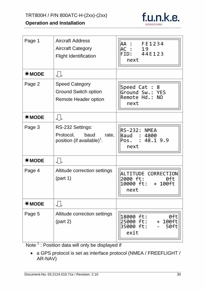
TRT800H PN 800ATC-H-(2xx)-(2xx)
Operation and Installation
31 Document-No 03212401071e Revision 210
GPS receiver is connected and transmits data (if not ldquoPos no datardquo is displayed)
a valid position is transmitted (if not ldquoPos wrong datardquo is displayed)
While configuration summary page is displayed no new position data will be processed
43 General settings
431 ICAO 24-Bit Aircraft Address (AA)
Ask your national aviation authority (e g in Germany LBA Referat B5 Department ldquoVerkehrszulassungrdquo) how to obtain the AA In the case of aerial sports equipment the contact point would be the respective associations Only the assigned AA has to be used and must not be modified at any time because a duplicate address would jeopardize the data surveillance and integrity figures of Mode S
If no AA is stored after power on the display shows ldquoCRADLE OFFrdquo and the transponder operates in Mode AC
(Configuration of the AA see section 454)
432 Aircraft Category (AC)
Code Description Code Description
11 Emergency Vehicle 1C Ultra-Light Paraglider
12 Service Vehicle 1E Drone
19 Glider 21 Aircraft (D-Exxx) lt 15500 lbs Motor Glider (D-Kxxx)
1A Balloon amp Airship 22 Aircraft ge 15500 lbslt 75000 lbs
1B Paratrooper 27 Rotorcraft
Only one of the Codes mentioned in the table above must be used
Setuprarr454
Setuprarr454
TRT800H PN 800ATC-H-(2xx)-(2xx)
Operation and Installation
32 Document-No 03212401071e Revision 210
433 Flight-ID (FID)
Per ICAO regulation Mode-S data must contain a valid flight identification (FID) to ensure that the correlation between flight plan and radar data will work automatically
FID setting is required to correspond to the aircraft identification that has been specified at item 7 of the ICAO flight plan It contains seven characters at a maximum (left-aligned no additional zeros dashes or spacesblanks)
For an aircraft using a company call sign the Flight-ID mostly consists of the ICAO three-letter designator for the aircraft operator followed by an identification code eg KLM511 BAW213 JTR25
If no company call sign is used or no flight plan is filed the default FID to be set consists of the registration marking of the aircraft (eg DEABC) with no dashes spacesblanks or additional zeros even if they are included in the registration marking on the aircraft (tail number) While entering the FID into the transponder the last remaining digits must be filled with blanks
The ICAO Flight Plan only specifies 7 characters for FID funke AVIONICS reserves 8 characters as stated in ED-73B for further expansion of the flight plan
The user shall only program 7 characters for FID
Setuprarr454
TRT800H PN 800ATC-H-(2xx)-(2xx)
Operation and Installation
33 Document-No 03212401071e Revision 210
434 Reply Information - Speed Category (RI)
Besides AA AC and FID another important part of the Mode-S data is the Speed Category of the respective aircraft This speed category shall be configured in the setup and must contain one of the following codes
Code Description
08 No maximum airspeed data available
09 Maximum airspeed le 75 kt
10 75 kt gt maximum airspeed le 150 kt
11 150 kt gt maximum airspeed le 300 kt
12 300 kt gt maximum airspeed le 600 kt
13 600 kt gt maximum airspeed le 1200 kt
14 Maximum airspeed gt 1200 kt
15 Not assigned
44 Optional settings
441 Option Ground-Switch
If a ground switch is connected (and enabled in setup) the transponder is able to determine on-ground and in-flight state On-ground state is activated automatically once the gear touches the ground On-ground state is indicated on display by symbol G (apart from lsquoFrsquo for In-flight-state)
In On-ground-state the transponder will reply differently to certain addressed interrogations Also the transmission rate of some periodically sent data (squitters ADS-B) is reduced This allows ATC to distinguish between airborne aircraft and those on the ground and it reduces the Mode S channel load
For small aircraft authorities normally do not require such a ground switch In this case the transponder will use the same data formats on the ground as in the airborne state
Setuprarr454 Wiringrarr373
Setuprarr454
TRT800H PN 800ATC-H-(2xx)-(2xx)
Operation and Installation
34 Document-No 03212401071e Revision 210
442 Option Remote Header
The transponder provides a TRT800RT remote control interface If a remote header TRT800RT is connected transponder can be remote controlled via this interface Remote interface provides control of all standard user inputs available during standard operational mode For more information see TRT800RT manual Remote control interface de-activation is setup configurable Remote control interface must only be connected to TRT800RT
443 Serial Interface (RS232)
Using serial interface a GPS receiver can be connected to broadcast own position via ADS-B Out position message Position could be received by other appropriately equipped aircrafts and processed for collision avoidance ADS-B Out functionality
The ADS-B function of this device has not been evaluated during the FAA TSO certification process other than to ensure non-interference Due to the SW assurance of DAL D the ADS-B function cannot be used in the US National Airspace Connecting a GPS source will not comply to FAA certification requirements with regard to ADS-B
Supported formatsprotocols are
Option Description Baud rate
FREEFLIGHT GPSWAAS Sensor 1201
NexNav NNL 3101
19200
AR-NAV Bendix King
KLN 89B KLN 94 ldquoStandard RS232 Sentencerdquo
KMD 150 ldquoSentence Type 1rdquo
Garmin 400 Series ldquoSentence Type 1rdquo (with and without altitude data)
9600
NMEA NMEA-Format data format RMC is expected
4800
Setuprarr454 Wiringrarr373
Setuprarr454 Wiringrarr373
TRT800H PN 800ATC-H-(2xx)-(2xx)
Operation and Installation
35 Document-No 03212401071e Revision 210
Option Description Baud rate
FAVISIA Glass Cockpit support
FAVISIA Data format to be processed in FAVISIA avionics suite
-
FAVISIA+GPS Data format to be processed in FAVISIA avionics suite (output) and additional processing of incoming NMEA GPS-Receiver position data to support the ADS-B Out functionality
4800
Other
Comm-AB-support
Data format for special purpose An additional data link processor allows COMM-AB operation and processing of the position information of a flight management system simultaneously
38400
Disabled No communication via RS232 interface -
444 Altitude CorrectionOffset
The TRT800H has an integrated temperature compensated high-precision pressure sensor This sensor is factory-calibrated so that it will yield accurate flight level (uncorrected pressure altitude) within the entire altitude range
However due to differences in calibration of the TRT800H pressure sensor and the altimeter in the cockpit it may become necessary to adjust the TRT800H pressure readings so that the value indicated and transmitted by the TRT800H corresponds to the indication of the primary altimeter seen by the pilot within 125 feet (as specified in ETSO C88aSAE AS 8003)
Setting for all described GPS-systems
1 2 position messages per 2 sec
Setuprarr455
TRT800H PN 800ATC-H-(2xx)-(2xx)
Operation and Installation
36 Document-No 03212401071e Revision 210
The check for correspondence between the primary altimeter and the TRT800H is usually performed every 24 months as part of the aircrafts altimeter checks
Altitude correction is based on setup configurable offset values at five interpolation points ( 2000 8000 18000 25000 and 35000 ft)The offset value itself is limited to a range from -100 to + 100ft at each point (10ft steps)
45 Setup Procedure
Programming of the ICAOA 24-bit Aircraft Address and of the Aircraft Category shall be executed by qualified personnel only
A wrong Aircraft Address or Flight ID may cause serious problems ATC or with ACASTCAS systems
Pilot and owner are responsible for correctly set transponder data
451 Setup Menu Control
In order to access the functions described in the following paragraphs push and hold ID in Standby mode Release ID if desired counter value menu name is displayed to enter the menu The following menu entries are selectable
Count Displayed Name Function
03 FID FID is displayed
48 CHANGE FID Enter FID setup page
913 SHOW SETUP Enter setup summary listed on different pages (no changes possible)
2528 ENTER SETUP Enter transponder general configuration pages
3134 ALTITUDE CORRECTION
Enter altitude correction menu
TRT800H PN 800ATC-H-(2xx)-(2xx)
Operation and Installation
37 Document-No 03212401071e Revision 210
452 Transponder configurationrecord structure
Aircraft related parts of transponder configuration are stored in one out of eight possible records (record=presetting) Each record contains the following information
Aircraft Address (AA 24bit)
Aircraft category (AC)
Flight identification (FID 6-8 numbersletters)
RS-232 Interface setting (eg GPS protocol)
Ground-Switch setting (Installed YesNo)
Speed category (RI) of the respective aircraft
Remote Header setting (Installed YesNo)
User related settings (eg squawk codes display brightness) are stored once in one global record (transponder internally)
453 Transponder configurationrecord handling
At least one record is stored in external memory Up to 8 records can be additional be applied during setup process
If more than one record is applied the active record must be selected out of a list (determined by FID) during start-up of the transponder
Previously applied records can be deleted again by filling FID with zerorsquos only
454 General Setup
Any menu item can be passed by MODE If no changes are made the original settings will remain stored Modification of one menu item does not impact the others No entries will be deleted
TRT800H PN 800ATC-H-(2xx)-(2xx)
Operation and Installation
38 Document-No 03212401071e Revision 210
Step Display (Example)
1 Start-up Transponder
2 Ensure the transponder-mode is bdquoSTBYldquo If necessary change the mode by pressing MODE
3 Press ID A counter is shown at the upper-right corner Hold ID till ldquoENTER SETUPrdquo is displayed
4 After release of ID the first setup menu is displayed
5 helliphellipselect position (^)
rotary knobchange value
MODE
6 With the rotary knob you can select bdquoyesldquo if a Ground Switch is installed if not select ldquonordquo and proceed with step 7
MODE
Record 1
GND Switch YesNo
next
AA EF123456
AC 18
FID ^BCDEFG
next
AA EF123456
AC 18
FID ABCDEFG
next
ENTER SETUP 26
2000 FL 030
STBY 7000
TRT800H PN 800ATC-H-(2xx)-(2xx)
Operation and Installation
39 Document-No 03212401071e Revision 210
Step Display (Example)
7 At this stage the respective speed category shall be selected by using the rotary knob
MODE
8 At this stage a GPS receiver for ADS-B Out can be selected (Selectable by rotary knob)
MODE
9 At this stage remote interface for communication between TRT800H and remote header can be activated (Selectable by rotary knob)
Remote interface must only be activated if a remote header is connected
MODE
10 With ID further Records can now be created and configured as described in the aforementioned steps At start-up of the transponder one of the defined records with all associated configurations need to be selected
MODE
Records ID=Edit Records
EXIT
Record 1
REMOTE Header YesNo
next
Record 1
GPSINTEXT NMEA
next
Record 1
Speed Cat 08-15
next
TRT800H PN 800ATC-H-(2xx)-(2xx)
Operation and Installation
40 Document-No 03212401071e Revision 210
Step Display (Example)
11 You have now left the configuration mode and are back in normal operation
12 Switch off the transponder
13 Switch on the transponder Your ICAO 24-Bit Aircraft Address is now stored
TRT800H V53
FPGA-Vers 102
2000 FL 030
STBY 7000
TRT800H PN 800ATC-H-(2xx)-(2xx)
Operation and Installation
41 Document-No 03212401071e Revision 210
455 Altitude Correction Setup
Altitude correction setup shall be executed by qualified personnel only
Pilot and owner are responsible for correctly set altitude offset values
The usesetting of altitude correction values is only necessary in exceptional cases (see 444 for details)
Altitude correction is based on five interpolation points ( 2000 10000 18000 25000 and 35000 ft)The offset value at each interpolation point can be adjusted in a range from -100 to + 100ft at each point (10ft steps) Offset values set to zero at each interpolation point deactivates altitude correction (defaultfactory setting)
Step Display (Example)
1 Start-up Transponder
2 Ensure the transponder-mode is bdquoSTBYldquo If necessary change the mode by pressing MODE
3 Press ID A counter is shown at the upper-right corner Hold ID till ldquoALTITUDE OFFSETrdquo is displayed
ALTITUDE OFFSET 33
2000 FL 030
STBY 7000
Descriptionrarr444
TRT800H PN 800ATC-H-(2xx)-(2xx)
Operation and Installation
42 Document-No 03212401071e Revision 210
Step Display (Example)
4 After release of ID the first altitude level + corresponding offset value is displayed
5 Change offset value with rotary knob
MODE
6 (9) Repeat last step for another 4 altitude levels 10000ft 18000ft 25000ft 35000ft
MODE
10 You have now left the configuration mode and are back in normal operation
Switch off the transponder
11 Switch on the transponder New altitude offset values will now be used for altitude calculation
Altitude 10000 ft
Offset 0 ft
nextexit
Altitude 2000 ft
Offset 0 ft
next
TRT800H V53
FPGA-Vers 102
2000 FL 030
STBY 7000
Altitude 2000 ft
Offset 0 ft
next
TRT800H PN 800ATC-H-(2xx)-(2xx)
Operation and Installation
43 Document-No 03212401071e Revision 210
5 APPENDIX
51 Technical Data
Compliance CS-ETSO-2C112a
EASA21O269
FAA TSO-C112c
Applicable Documents CS-ETSO-2C112a
FAA TSO-C112c
EUROCAE ED-73C Class 1 Level 2es
RTCA DO-181D Class 1 Level 2es
EUROCAE ED-26
RTCA DO-160D
RTCA DO-178B Software-Level D
Temperature Ranges
Operation -20 degC to +55 degC for 30 min +70degC
Storage -55 degC to +85 degC
Altitude Range le 35 000 ft
Speed Range le 250 kt (TAS)
Shock 6 G Operation
20 G crash safety
Environmental Categories RTCA DO-160D EnvCat [C1Z]CAA[SM]XXXXXXZBAAA[TT]M[B3F3]XXA
Power Supply 138 VDC (10 VDC 16 VDC)
040 A 138 VDC (typ)
070 A 138 VDC (max)
10 W (max)
TRT800H PN 800ATC-H-(2xx)-(2xx)
Operation and Installation
44 Document-No 03212401071e Revision 210
Fuse External 2A-slow-blow fuse
Mounting Panel cut-out d=575 mm
Weight 06 kg (132 lbs)
Receiver Characteristics
Sensitivity
RF input power level resulting in a 90 reply rate
A MTL for ATCRBS and ATCRBSMode S All-Call interrogations -74 dBm plusmn3 dB
B MTL for Mode S interrogations -74 dBm plusmn 3 dB
Reply transmission frequency
1090 plusmn 1 MHz
RF Peak Power Output 21 dBW (126 W) at antenna base (with maximum cable attenuation of 15 dB)
Squitter (ADS-B) transmitted at random intervals uniformly distributed over the range from 08 to 12 seconds full self-verification of data and occurrence
Mode S Elementary Surveillance
ICAO 24-bit Aircraft Address (Hex-Code)
aircraft address as assigned by national aviation authority
FID Flight ID Flight Plan call sign or aircraft registration marking
Capability Report Reports the available data and means by which the transponder can report
Pressure Altitude Up to 35 000 ft in 25 ft increments
Flight Status in-flight on-ground
Mode S Enhanced Surveillance
Level 2es Comm-A Comm-B 56112-Bit-Messages
SI-capability
TRT800H PN 800ATC-H-(2xx)-(2xx)
Operation and Installation
45 Document-No 03212401071e Revision 210
52 Environmental Conditions
Characteristic DOndash160D Section Cat Condition
Temperature Altitude 40
C1
Low ground survival temperature
451 ndash 55degC
Low operating temperature 451 ndash 20degC
High ground survival Temperature
452 + 85degC
High Short-time Operating Temperature
452 + 70degC
High Operating Temperature 453 + 55degC
In-Flight Loss of Cooling 454 Z No auxiliary cooling required
Altitude 461 C1 35 000 ft
Temperature Variation 50 C 2degC change rate minimum per minute
Humidity 60 A
Shock 70 A
6 G operational shocks
20 G Crash Safety
Test Type R in all 6 directions
Vibration 80 S Vibration Curve M
Explosion Proofness 90 X No test required
Water Proofness 100 X No test required
Fluids Susceptibilities 110 X No test required
Sand and Dust 120 X No test required
Fungus Resistance 130 X No test required
Salt Spray 140 X No test required
Magnetic Effect 150 Z Less than 03 m
Power Input (DC) 160 B
Voltage Spike Conducted 170 A
Audio Frequency Conducted Susceptibility
180 A
TRT800H PN 800ATC-H-(2xx)-(2xx)
Operation and Installation
46 Document-No 03212401071e Revision 210
Characteristic DOndash160D Section Cat Condition
Induced Signal Susceptibility 190 A
Radio Frequency Susceptibility
200 TT
Emission of RF Energy 210 M
Lightning Induced Transient Susceptibility
220 B3F3
Lightning Direct Effects 230 X No test required
Icing 240 X No test required
Electrostatic Discharge (ESD) 250 A
53 DO-178B Open Problem Reports
There are no open problem reports for the software of this device
TRT800H PN 800ATC-H-(2xx)-(2xx)
Operation and Installation
47 Document-No 03212401071e Revision 210
Notes
f funke funke means ndash fabrication utilities network know-how engineering
funke AVIONICS GmbH Heinz-Strachowitz-Str 4
DE-86807 Buchloe Germany
phone +49-8241 80066 0
fax +49-8241 80066 99 E-mail
servicefunkeavionicsde wwwfunkeavionicsde
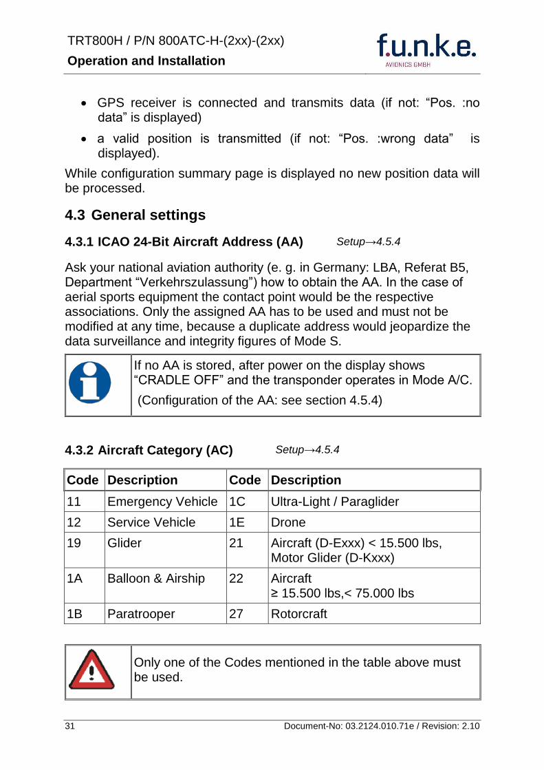
TRT800H PN 800ATC-H-(2xx)-(2xx)
Operation and Installation
32 Document-No 03212401071e Revision 210
433 Flight-ID (FID)
Per ICAO regulation Mode-S data must contain a valid flight identification (FID) to ensure that the correlation between flight plan and radar data will work automatically
FID setting is required to correspond to the aircraft identification that has been specified at item 7 of the ICAO flight plan It contains seven characters at a maximum (left-aligned no additional zeros dashes or spacesblanks)
For an aircraft using a company call sign the Flight-ID mostly consists of the ICAO three-letter designator for the aircraft operator followed by an identification code eg KLM511 BAW213 JTR25
If no company call sign is used or no flight plan is filed the default FID to be set consists of the registration marking of the aircraft (eg DEABC) with no dashes spacesblanks or additional zeros even if they are included in the registration marking on the aircraft (tail number) While entering the FID into the transponder the last remaining digits must be filled with blanks
The ICAO Flight Plan only specifies 7 characters for FID funke AVIONICS reserves 8 characters as stated in ED-73B for further expansion of the flight plan
The user shall only program 7 characters for FID
Setuprarr454
TRT800H PN 800ATC-H-(2xx)-(2xx)
Operation and Installation
33 Document-No 03212401071e Revision 210
434 Reply Information - Speed Category (RI)
Besides AA AC and FID another important part of the Mode-S data is the Speed Category of the respective aircraft This speed category shall be configured in the setup and must contain one of the following codes
Code Description
08 No maximum airspeed data available
09 Maximum airspeed le 75 kt
10 75 kt gt maximum airspeed le 150 kt
11 150 kt gt maximum airspeed le 300 kt
12 300 kt gt maximum airspeed le 600 kt
13 600 kt gt maximum airspeed le 1200 kt
14 Maximum airspeed gt 1200 kt
15 Not assigned
44 Optional settings
441 Option Ground-Switch
If a ground switch is connected (and enabled in setup) the transponder is able to determine on-ground and in-flight state On-ground state is activated automatically once the gear touches the ground On-ground state is indicated on display by symbol G (apart from lsquoFrsquo for In-flight-state)
In On-ground-state the transponder will reply differently to certain addressed interrogations Also the transmission rate of some periodically sent data (squitters ADS-B) is reduced This allows ATC to distinguish between airborne aircraft and those on the ground and it reduces the Mode S channel load
For small aircraft authorities normally do not require such a ground switch In this case the transponder will use the same data formats on the ground as in the airborne state
Setuprarr454 Wiringrarr373
Setuprarr454
TRT800H PN 800ATC-H-(2xx)-(2xx)
Operation and Installation
34 Document-No 03212401071e Revision 210
442 Option Remote Header
The transponder provides a TRT800RT remote control interface If a remote header TRT800RT is connected transponder can be remote controlled via this interface Remote interface provides control of all standard user inputs available during standard operational mode For more information see TRT800RT manual Remote control interface de-activation is setup configurable Remote control interface must only be connected to TRT800RT
443 Serial Interface (RS232)
Using serial interface a GPS receiver can be connected to broadcast own position via ADS-B Out position message Position could be received by other appropriately equipped aircrafts and processed for collision avoidance ADS-B Out functionality
The ADS-B function of this device has not been evaluated during the FAA TSO certification process other than to ensure non-interference Due to the SW assurance of DAL D the ADS-B function cannot be used in the US National Airspace Connecting a GPS source will not comply to FAA certification requirements with regard to ADS-B
Supported formatsprotocols are
Option Description Baud rate
FREEFLIGHT GPSWAAS Sensor 1201
NexNav NNL 3101
19200
AR-NAV Bendix King
KLN 89B KLN 94 ldquoStandard RS232 Sentencerdquo
KMD 150 ldquoSentence Type 1rdquo
Garmin 400 Series ldquoSentence Type 1rdquo (with and without altitude data)
9600
NMEA NMEA-Format data format RMC is expected
4800
Setuprarr454 Wiringrarr373
Setuprarr454 Wiringrarr373
TRT800H PN 800ATC-H-(2xx)-(2xx)
Operation and Installation
35 Document-No 03212401071e Revision 210
Option Description Baud rate
FAVISIA Glass Cockpit support
FAVISIA Data format to be processed in FAVISIA avionics suite
-
FAVISIA+GPS Data format to be processed in FAVISIA avionics suite (output) and additional processing of incoming NMEA GPS-Receiver position data to support the ADS-B Out functionality
4800
Other
Comm-AB-support
Data format for special purpose An additional data link processor allows COMM-AB operation and processing of the position information of a flight management system simultaneously
38400
Disabled No communication via RS232 interface -
444 Altitude CorrectionOffset
The TRT800H has an integrated temperature compensated high-precision pressure sensor This sensor is factory-calibrated so that it will yield accurate flight level (uncorrected pressure altitude) within the entire altitude range
However due to differences in calibration of the TRT800H pressure sensor and the altimeter in the cockpit it may become necessary to adjust the TRT800H pressure readings so that the value indicated and transmitted by the TRT800H corresponds to the indication of the primary altimeter seen by the pilot within 125 feet (as specified in ETSO C88aSAE AS 8003)
Setting for all described GPS-systems
1 2 position messages per 2 sec
Setuprarr455
TRT800H PN 800ATC-H-(2xx)-(2xx)
Operation and Installation
36 Document-No 03212401071e Revision 210
The check for correspondence between the primary altimeter and the TRT800H is usually performed every 24 months as part of the aircrafts altimeter checks
Altitude correction is based on setup configurable offset values at five interpolation points ( 2000 8000 18000 25000 and 35000 ft)The offset value itself is limited to a range from -100 to + 100ft at each point (10ft steps)
45 Setup Procedure
Programming of the ICAOA 24-bit Aircraft Address and of the Aircraft Category shall be executed by qualified personnel only
A wrong Aircraft Address or Flight ID may cause serious problems ATC or with ACASTCAS systems
Pilot and owner are responsible for correctly set transponder data
451 Setup Menu Control
In order to access the functions described in the following paragraphs push and hold ID in Standby mode Release ID if desired counter value menu name is displayed to enter the menu The following menu entries are selectable
Count Displayed Name Function
03 FID FID is displayed
48 CHANGE FID Enter FID setup page
913 SHOW SETUP Enter setup summary listed on different pages (no changes possible)
2528 ENTER SETUP Enter transponder general configuration pages
3134 ALTITUDE CORRECTION
Enter altitude correction menu
TRT800H PN 800ATC-H-(2xx)-(2xx)
Operation and Installation
37 Document-No 03212401071e Revision 210
452 Transponder configurationrecord structure
Aircraft related parts of transponder configuration are stored in one out of eight possible records (record=presetting) Each record contains the following information
Aircraft Address (AA 24bit)
Aircraft category (AC)
Flight identification (FID 6-8 numbersletters)
RS-232 Interface setting (eg GPS protocol)
Ground-Switch setting (Installed YesNo)
Speed category (RI) of the respective aircraft
Remote Header setting (Installed YesNo)
User related settings (eg squawk codes display brightness) are stored once in one global record (transponder internally)
453 Transponder configurationrecord handling
At least one record is stored in external memory Up to 8 records can be additional be applied during setup process
If more than one record is applied the active record must be selected out of a list (determined by FID) during start-up of the transponder
Previously applied records can be deleted again by filling FID with zerorsquos only
454 General Setup
Any menu item can be passed by MODE If no changes are made the original settings will remain stored Modification of one menu item does not impact the others No entries will be deleted
TRT800H PN 800ATC-H-(2xx)-(2xx)
Operation and Installation
38 Document-No 03212401071e Revision 210
Step Display (Example)
1 Start-up Transponder
2 Ensure the transponder-mode is bdquoSTBYldquo If necessary change the mode by pressing MODE
3 Press ID A counter is shown at the upper-right corner Hold ID till ldquoENTER SETUPrdquo is displayed
4 After release of ID the first setup menu is displayed
5 helliphellipselect position (^)
rotary knobchange value
MODE
6 With the rotary knob you can select bdquoyesldquo if a Ground Switch is installed if not select ldquonordquo and proceed with step 7
MODE
Record 1
GND Switch YesNo
next
AA EF123456
AC 18
FID ^BCDEFG
next
AA EF123456
AC 18
FID ABCDEFG
next
ENTER SETUP 26
2000 FL 030
STBY 7000
TRT800H PN 800ATC-H-(2xx)-(2xx)
Operation and Installation
39 Document-No 03212401071e Revision 210
Step Display (Example)
7 At this stage the respective speed category shall be selected by using the rotary knob
MODE
8 At this stage a GPS receiver for ADS-B Out can be selected (Selectable by rotary knob)
MODE
9 At this stage remote interface for communication between TRT800H and remote header can be activated (Selectable by rotary knob)
Remote interface must only be activated if a remote header is connected
MODE
10 With ID further Records can now be created and configured as described in the aforementioned steps At start-up of the transponder one of the defined records with all associated configurations need to be selected
MODE
Records ID=Edit Records
EXIT
Record 1
REMOTE Header YesNo
next
Record 1
GPSINTEXT NMEA
next
Record 1
Speed Cat 08-15
next
TRT800H PN 800ATC-H-(2xx)-(2xx)
Operation and Installation
40 Document-No 03212401071e Revision 210
Step Display (Example)
11 You have now left the configuration mode and are back in normal operation
12 Switch off the transponder
13 Switch on the transponder Your ICAO 24-Bit Aircraft Address is now stored
TRT800H V53
FPGA-Vers 102
2000 FL 030
STBY 7000
TRT800H PN 800ATC-H-(2xx)-(2xx)
Operation and Installation
41 Document-No 03212401071e Revision 210
455 Altitude Correction Setup
Altitude correction setup shall be executed by qualified personnel only
Pilot and owner are responsible for correctly set altitude offset values
The usesetting of altitude correction values is only necessary in exceptional cases (see 444 for details)
Altitude correction is based on five interpolation points ( 2000 10000 18000 25000 and 35000 ft)The offset value at each interpolation point can be adjusted in a range from -100 to + 100ft at each point (10ft steps) Offset values set to zero at each interpolation point deactivates altitude correction (defaultfactory setting)
Step Display (Example)
1 Start-up Transponder
2 Ensure the transponder-mode is bdquoSTBYldquo If necessary change the mode by pressing MODE
3 Press ID A counter is shown at the upper-right corner Hold ID till ldquoALTITUDE OFFSETrdquo is displayed
ALTITUDE OFFSET 33
2000 FL 030
STBY 7000
Descriptionrarr444
TRT800H PN 800ATC-H-(2xx)-(2xx)
Operation and Installation
42 Document-No 03212401071e Revision 210
Step Display (Example)
4 After release of ID the first altitude level + corresponding offset value is displayed
5 Change offset value with rotary knob
MODE
6 (9) Repeat last step for another 4 altitude levels 10000ft 18000ft 25000ft 35000ft
MODE
10 You have now left the configuration mode and are back in normal operation
Switch off the transponder
11 Switch on the transponder New altitude offset values will now be used for altitude calculation
Altitude 10000 ft
Offset 0 ft
nextexit
Altitude 2000 ft
Offset 0 ft
next
TRT800H V53
FPGA-Vers 102
2000 FL 030
STBY 7000
Altitude 2000 ft
Offset 0 ft
next
TRT800H PN 800ATC-H-(2xx)-(2xx)
Operation and Installation
43 Document-No 03212401071e Revision 210
5 APPENDIX
51 Technical Data
Compliance CS-ETSO-2C112a
EASA21O269
FAA TSO-C112c
Applicable Documents CS-ETSO-2C112a
FAA TSO-C112c
EUROCAE ED-73C Class 1 Level 2es
RTCA DO-181D Class 1 Level 2es
EUROCAE ED-26
RTCA DO-160D
RTCA DO-178B Software-Level D
Temperature Ranges
Operation -20 degC to +55 degC for 30 min +70degC
Storage -55 degC to +85 degC
Altitude Range le 35 000 ft
Speed Range le 250 kt (TAS)
Shock 6 G Operation
20 G crash safety
Environmental Categories RTCA DO-160D EnvCat [C1Z]CAA[SM]XXXXXXZBAAA[TT]M[B3F3]XXA
Power Supply 138 VDC (10 VDC 16 VDC)
040 A 138 VDC (typ)
070 A 138 VDC (max)
10 W (max)
TRT800H PN 800ATC-H-(2xx)-(2xx)
Operation and Installation
44 Document-No 03212401071e Revision 210
Fuse External 2A-slow-blow fuse
Mounting Panel cut-out d=575 mm
Weight 06 kg (132 lbs)
Receiver Characteristics
Sensitivity
RF input power level resulting in a 90 reply rate
A MTL for ATCRBS and ATCRBSMode S All-Call interrogations -74 dBm plusmn3 dB
B MTL for Mode S interrogations -74 dBm plusmn 3 dB
Reply transmission frequency
1090 plusmn 1 MHz
RF Peak Power Output 21 dBW (126 W) at antenna base (with maximum cable attenuation of 15 dB)
Squitter (ADS-B) transmitted at random intervals uniformly distributed over the range from 08 to 12 seconds full self-verification of data and occurrence
Mode S Elementary Surveillance
ICAO 24-bit Aircraft Address (Hex-Code)
aircraft address as assigned by national aviation authority
FID Flight ID Flight Plan call sign or aircraft registration marking
Capability Report Reports the available data and means by which the transponder can report
Pressure Altitude Up to 35 000 ft in 25 ft increments
Flight Status in-flight on-ground
Mode S Enhanced Surveillance
Level 2es Comm-A Comm-B 56112-Bit-Messages
SI-capability
TRT800H PN 800ATC-H-(2xx)-(2xx)
Operation and Installation
45 Document-No 03212401071e Revision 210
52 Environmental Conditions
Characteristic DOndash160D Section Cat Condition
Temperature Altitude 40
C1
Low ground survival temperature
451 ndash 55degC
Low operating temperature 451 ndash 20degC
High ground survival Temperature
452 + 85degC
High Short-time Operating Temperature
452 + 70degC
High Operating Temperature 453 + 55degC
In-Flight Loss of Cooling 454 Z No auxiliary cooling required
Altitude 461 C1 35 000 ft
Temperature Variation 50 C 2degC change rate minimum per minute
Humidity 60 A
Shock 70 A
6 G operational shocks
20 G Crash Safety
Test Type R in all 6 directions
Vibration 80 S Vibration Curve M
Explosion Proofness 90 X No test required
Water Proofness 100 X No test required
Fluids Susceptibilities 110 X No test required
Sand and Dust 120 X No test required
Fungus Resistance 130 X No test required
Salt Spray 140 X No test required
Magnetic Effect 150 Z Less than 03 m
Power Input (DC) 160 B
Voltage Spike Conducted 170 A
Audio Frequency Conducted Susceptibility
180 A
TRT800H PN 800ATC-H-(2xx)-(2xx)
Operation and Installation
46 Document-No 03212401071e Revision 210
Characteristic DOndash160D Section Cat Condition
Induced Signal Susceptibility 190 A
Radio Frequency Susceptibility
200 TT
Emission of RF Energy 210 M
Lightning Induced Transient Susceptibility
220 B3F3
Lightning Direct Effects 230 X No test required
Icing 240 X No test required
Electrostatic Discharge (ESD) 250 A
53 DO-178B Open Problem Reports
There are no open problem reports for the software of this device
TRT800H PN 800ATC-H-(2xx)-(2xx)
Operation and Installation
47 Document-No 03212401071e Revision 210
Notes
f funke funke means ndash fabrication utilities network know-how engineering
funke AVIONICS GmbH Heinz-Strachowitz-Str 4
DE-86807 Buchloe Germany
phone +49-8241 80066 0
fax +49-8241 80066 99 E-mail
servicefunkeavionicsde wwwfunkeavionicsde
TRT800H PN 800ATC-H-(2xx)-(2xx)
Operation and Installation
34 Document-No 03212401071e Revision 210
442 Option Remote Header
The transponder provides a TRT800RT remote control interface If a remote header TRT800RT is connected transponder can be remote controlled via this interface Remote interface provides control of all standard user inputs available during standard operational mode For more information see TRT800RT manual Remote control interface de-activation is setup configurable Remote control interface must only be connected to TRT800RT
443 Serial Interface (RS232)
Using serial interface a GPS receiver can be connected to broadcast own position via ADS-B Out position message Position could be received by other appropriately equipped aircrafts and processed for collision avoidance ADS-B Out functionality
The ADS-B function of this device has not been evaluated during the FAA TSO certification process other than to ensure non-interference Due to the SW assurance of DAL D the ADS-B function cannot be used in the US National Airspace Connecting a GPS source will not comply to FAA certification requirements with regard to ADS-B
Supported formatsprotocols are
Option Description Baud rate
FREEFLIGHT GPSWAAS Sensor 1201
NexNav NNL 3101
19200
AR-NAV Bendix King
KLN 89B KLN 94 ldquoStandard RS232 Sentencerdquo
KMD 150 ldquoSentence Type 1rdquo
Garmin 400 Series ldquoSentence Type 1rdquo (with and without altitude data)
9600
NMEA NMEA-Format data format RMC is expected
4800
Setuprarr454 Wiringrarr373
Setuprarr454 Wiringrarr373
TRT800H PN 800ATC-H-(2xx)-(2xx)
Operation and Installation
35 Document-No 03212401071e Revision 210
Option Description Baud rate
FAVISIA Glass Cockpit support
FAVISIA Data format to be processed in FAVISIA avionics suite
-
FAVISIA+GPS Data format to be processed in FAVISIA avionics suite (output) and additional processing of incoming NMEA GPS-Receiver position data to support the ADS-B Out functionality
4800
Other
Comm-AB-support
Data format for special purpose An additional data link processor allows COMM-AB operation and processing of the position information of a flight management system simultaneously
38400
Disabled No communication via RS232 interface -
444 Altitude CorrectionOffset
The TRT800H has an integrated temperature compensated high-precision pressure sensor This sensor is factory-calibrated so that it will yield accurate flight level (uncorrected pressure altitude) within the entire altitude range
However due to differences in calibration of the TRT800H pressure sensor and the altimeter in the cockpit it may become necessary to adjust the TRT800H pressure readings so that the value indicated and transmitted by the TRT800H corresponds to the indication of the primary altimeter seen by the pilot within 125 feet (as specified in ETSO C88aSAE AS 8003)
Setting for all described GPS-systems
1 2 position messages per 2 sec
Setuprarr455
TRT800H PN 800ATC-H-(2xx)-(2xx)
Operation and Installation
36 Document-No 03212401071e Revision 210
The check for correspondence between the primary altimeter and the TRT800H is usually performed every 24 months as part of the aircrafts altimeter checks
Altitude correction is based on setup configurable offset values at five interpolation points ( 2000 8000 18000 25000 and 35000 ft)The offset value itself is limited to a range from -100 to + 100ft at each point (10ft steps)
45 Setup Procedure
Programming of the ICAOA 24-bit Aircraft Address and of the Aircraft Category shall be executed by qualified personnel only
A wrong Aircraft Address or Flight ID may cause serious problems ATC or with ACASTCAS systems
Pilot and owner are responsible for correctly set transponder data
451 Setup Menu Control
In order to access the functions described in the following paragraphs push and hold ID in Standby mode Release ID if desired counter value menu name is displayed to enter the menu The following menu entries are selectable
Count Displayed Name Function
03 FID FID is displayed
48 CHANGE FID Enter FID setup page
913 SHOW SETUP Enter setup summary listed on different pages (no changes possible)
2528 ENTER SETUP Enter transponder general configuration pages
3134 ALTITUDE CORRECTION
Enter altitude correction menu
TRT800H PN 800ATC-H-(2xx)-(2xx)
Operation and Installation
37 Document-No 03212401071e Revision 210
452 Transponder configurationrecord structure
Aircraft related parts of transponder configuration are stored in one out of eight possible records (record=presetting) Each record contains the following information
Aircraft Address (AA 24bit)
Aircraft category (AC)
Flight identification (FID 6-8 numbersletters)
RS-232 Interface setting (eg GPS protocol)
Ground-Switch setting (Installed YesNo)
Speed category (RI) of the respective aircraft
Remote Header setting (Installed YesNo)
User related settings (eg squawk codes display brightness) are stored once in one global record (transponder internally)
453 Transponder configurationrecord handling
At least one record is stored in external memory Up to 8 records can be additional be applied during setup process
If more than one record is applied the active record must be selected out of a list (determined by FID) during start-up of the transponder
Previously applied records can be deleted again by filling FID with zerorsquos only
454 General Setup
Any menu item can be passed by MODE If no changes are made the original settings will remain stored Modification of one menu item does not impact the others No entries will be deleted
TRT800H PN 800ATC-H-(2xx)-(2xx)
Operation and Installation
38 Document-No 03212401071e Revision 210
Step Display (Example)
1 Start-up Transponder
2 Ensure the transponder-mode is bdquoSTBYldquo If necessary change the mode by pressing MODE
3 Press ID A counter is shown at the upper-right corner Hold ID till ldquoENTER SETUPrdquo is displayed
4 After release of ID the first setup menu is displayed
5 helliphellipselect position (^)
rotary knobchange value
MODE
6 With the rotary knob you can select bdquoyesldquo if a Ground Switch is installed if not select ldquonordquo and proceed with step 7
MODE
Record 1
GND Switch YesNo
next
AA EF123456
AC 18
FID ^BCDEFG
next
AA EF123456
AC 18
FID ABCDEFG
next
ENTER SETUP 26
2000 FL 030
STBY 7000
TRT800H PN 800ATC-H-(2xx)-(2xx)
Operation and Installation
39 Document-No 03212401071e Revision 210
Step Display (Example)
7 At this stage the respective speed category shall be selected by using the rotary knob
MODE
8 At this stage a GPS receiver for ADS-B Out can be selected (Selectable by rotary knob)
MODE
9 At this stage remote interface for communication between TRT800H and remote header can be activated (Selectable by rotary knob)
Remote interface must only be activated if a remote header is connected
MODE
10 With ID further Records can now be created and configured as described in the aforementioned steps At start-up of the transponder one of the defined records with all associated configurations need to be selected
MODE
Records ID=Edit Records
EXIT
Record 1
REMOTE Header YesNo
next
Record 1
GPSINTEXT NMEA
next
Record 1
Speed Cat 08-15
next
TRT800H PN 800ATC-H-(2xx)-(2xx)
Operation and Installation
40 Document-No 03212401071e Revision 210
Step Display (Example)
11 You have now left the configuration mode and are back in normal operation
12 Switch off the transponder
13 Switch on the transponder Your ICAO 24-Bit Aircraft Address is now stored
TRT800H V53
FPGA-Vers 102
2000 FL 030
STBY 7000
TRT800H PN 800ATC-H-(2xx)-(2xx)
Operation and Installation
41 Document-No 03212401071e Revision 210
455 Altitude Correction Setup
Altitude correction setup shall be executed by qualified personnel only
Pilot and owner are responsible for correctly set altitude offset values
The usesetting of altitude correction values is only necessary in exceptional cases (see 444 for details)
Altitude correction is based on five interpolation points ( 2000 10000 18000 25000 and 35000 ft)The offset value at each interpolation point can be adjusted in a range from -100 to + 100ft at each point (10ft steps) Offset values set to zero at each interpolation point deactivates altitude correction (defaultfactory setting)
Step Display (Example)
1 Start-up Transponder
2 Ensure the transponder-mode is bdquoSTBYldquo If necessary change the mode by pressing MODE
3 Press ID A counter is shown at the upper-right corner Hold ID till ldquoALTITUDE OFFSETrdquo is displayed
ALTITUDE OFFSET 33
2000 FL 030
STBY 7000
Descriptionrarr444
TRT800H PN 800ATC-H-(2xx)-(2xx)
Operation and Installation
42 Document-No 03212401071e Revision 210
Step Display (Example)
4 After release of ID the first altitude level + corresponding offset value is displayed
5 Change offset value with rotary knob
MODE
6 (9) Repeat last step for another 4 altitude levels 10000ft 18000ft 25000ft 35000ft
MODE
10 You have now left the configuration mode and are back in normal operation
Switch off the transponder
11 Switch on the transponder New altitude offset values will now be used for altitude calculation
Altitude 10000 ft
Offset 0 ft
nextexit
Altitude 2000 ft
Offset 0 ft
next
TRT800H V53
FPGA-Vers 102
2000 FL 030
STBY 7000
Altitude 2000 ft
Offset 0 ft
next
TRT800H PN 800ATC-H-(2xx)-(2xx)
Operation and Installation
43 Document-No 03212401071e Revision 210
5 APPENDIX
51 Technical Data
Compliance CS-ETSO-2C112a
EASA21O269
FAA TSO-C112c
Applicable Documents CS-ETSO-2C112a
FAA TSO-C112c
EUROCAE ED-73C Class 1 Level 2es
RTCA DO-181D Class 1 Level 2es
EUROCAE ED-26
RTCA DO-160D
RTCA DO-178B Software-Level D
Temperature Ranges
Operation -20 degC to +55 degC for 30 min +70degC
Storage -55 degC to +85 degC
Altitude Range le 35 000 ft
Speed Range le 250 kt (TAS)
Shock 6 G Operation
20 G crash safety
Environmental Categories RTCA DO-160D EnvCat [C1Z]CAA[SM]XXXXXXZBAAA[TT]M[B3F3]XXA
Power Supply 138 VDC (10 VDC 16 VDC)
040 A 138 VDC (typ)
070 A 138 VDC (max)
10 W (max)
TRT800H PN 800ATC-H-(2xx)-(2xx)
Operation and Installation
44 Document-No 03212401071e Revision 210
Fuse External 2A-slow-blow fuse
Mounting Panel cut-out d=575 mm
Weight 06 kg (132 lbs)
Receiver Characteristics
Sensitivity
RF input power level resulting in a 90 reply rate
A MTL for ATCRBS and ATCRBSMode S All-Call interrogations -74 dBm plusmn3 dB
B MTL for Mode S interrogations -74 dBm plusmn 3 dB
Reply transmission frequency
1090 plusmn 1 MHz
RF Peak Power Output 21 dBW (126 W) at antenna base (with maximum cable attenuation of 15 dB)
Squitter (ADS-B) transmitted at random intervals uniformly distributed over the range from 08 to 12 seconds full self-verification of data and occurrence
Mode S Elementary Surveillance
ICAO 24-bit Aircraft Address (Hex-Code)
aircraft address as assigned by national aviation authority
FID Flight ID Flight Plan call sign or aircraft registration marking
Capability Report Reports the available data and means by which the transponder can report
Pressure Altitude Up to 35 000 ft in 25 ft increments
Flight Status in-flight on-ground
Mode S Enhanced Surveillance
Level 2es Comm-A Comm-B 56112-Bit-Messages
SI-capability
TRT800H PN 800ATC-H-(2xx)-(2xx)
Operation and Installation
45 Document-No 03212401071e Revision 210
52 Environmental Conditions
Characteristic DOndash160D Section Cat Condition
Temperature Altitude 40
C1
Low ground survival temperature
451 ndash 55degC
Low operating temperature 451 ndash 20degC
High ground survival Temperature
452 + 85degC
High Short-time Operating Temperature
452 + 70degC
High Operating Temperature 453 + 55degC
In-Flight Loss of Cooling 454 Z No auxiliary cooling required
Altitude 461 C1 35 000 ft
Temperature Variation 50 C 2degC change rate minimum per minute
Humidity 60 A
Shock 70 A
6 G operational shocks
20 G Crash Safety
Test Type R in all 6 directions
Vibration 80 S Vibration Curve M
Explosion Proofness 90 X No test required
Water Proofness 100 X No test required
Fluids Susceptibilities 110 X No test required
Sand and Dust 120 X No test required
Fungus Resistance 130 X No test required
Salt Spray 140 X No test required
Magnetic Effect 150 Z Less than 03 m
Power Input (DC) 160 B
Voltage Spike Conducted 170 A
Audio Frequency Conducted Susceptibility
180 A
TRT800H PN 800ATC-H-(2xx)-(2xx)
Operation and Installation
46 Document-No 03212401071e Revision 210
Characteristic DOndash160D Section Cat Condition
Induced Signal Susceptibility 190 A
Radio Frequency Susceptibility
200 TT
Emission of RF Energy 210 M
Lightning Induced Transient Susceptibility
220 B3F3
Lightning Direct Effects 230 X No test required
Icing 240 X No test required
Electrostatic Discharge (ESD) 250 A
53 DO-178B Open Problem Reports
There are no open problem reports for the software of this device
TRT800H PN 800ATC-H-(2xx)-(2xx)
Operation and Installation
47 Document-No 03212401071e Revision 210
Notes
f funke funke means ndash fabrication utilities network know-how engineering
funke AVIONICS GmbH Heinz-Strachowitz-Str 4
DE-86807 Buchloe Germany
phone +49-8241 80066 0
fax +49-8241 80066 99 E-mail
servicefunkeavionicsde wwwfunkeavionicsde
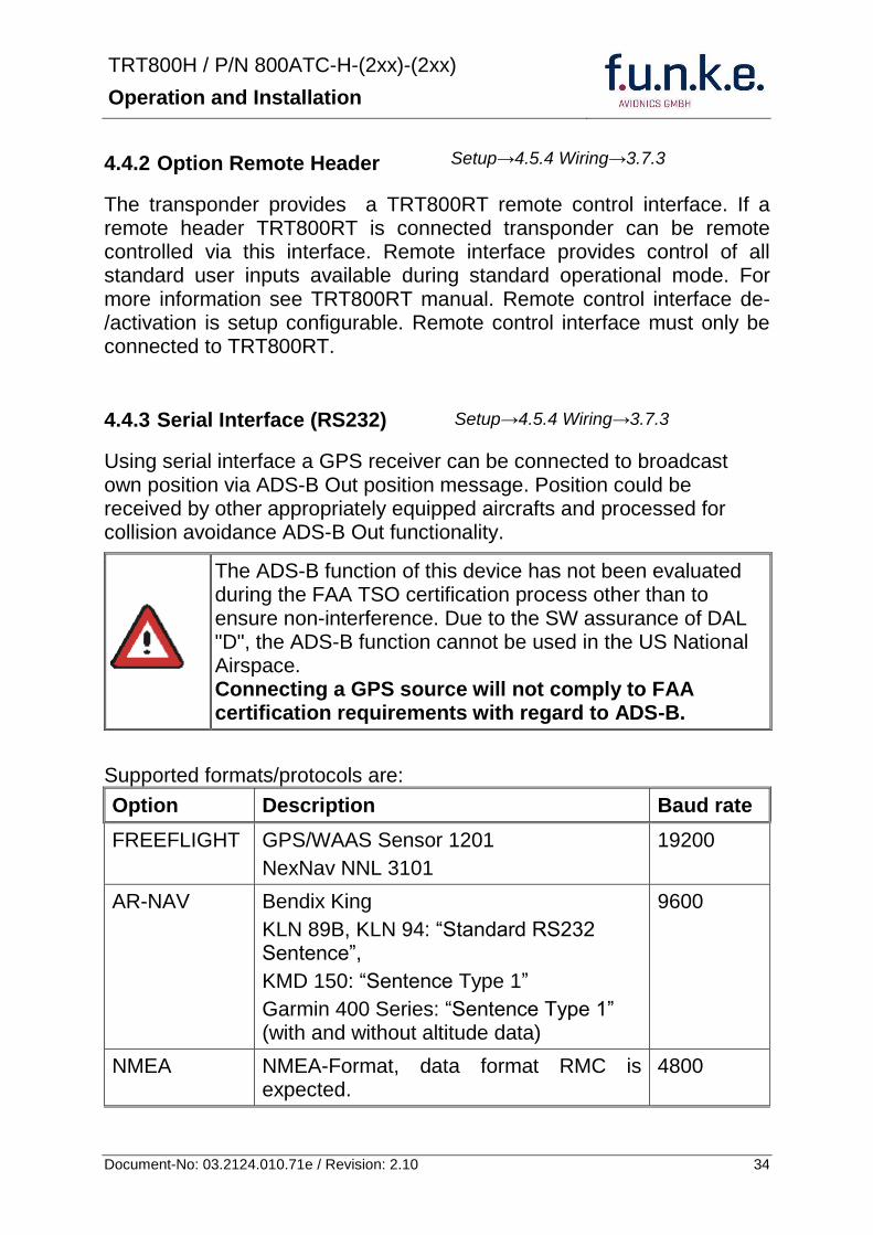
TRT800H PN 800ATC-H-(2xx)-(2xx)
Operation and Installation
35 Document-No 03212401071e Revision 210
Option Description Baud rate
FAVISIA Glass Cockpit support
FAVISIA Data format to be processed in FAVISIA avionics suite
-
FAVISIA+GPS Data format to be processed in FAVISIA avionics suite (output) and additional processing of incoming NMEA GPS-Receiver position data to support the ADS-B Out functionality
4800
Other
Comm-AB-support
Data format for special purpose An additional data link processor allows COMM-AB operation and processing of the position information of a flight management system simultaneously
38400
Disabled No communication via RS232 interface -
444 Altitude CorrectionOffset
The TRT800H has an integrated temperature compensated high-precision pressure sensor This sensor is factory-calibrated so that it will yield accurate flight level (uncorrected pressure altitude) within the entire altitude range
However due to differences in calibration of the TRT800H pressure sensor and the altimeter in the cockpit it may become necessary to adjust the TRT800H pressure readings so that the value indicated and transmitted by the TRT800H corresponds to the indication of the primary altimeter seen by the pilot within 125 feet (as specified in ETSO C88aSAE AS 8003)
Setting for all described GPS-systems
1 2 position messages per 2 sec
Setuprarr455
TRT800H PN 800ATC-H-(2xx)-(2xx)
Operation and Installation
36 Document-No 03212401071e Revision 210
The check for correspondence between the primary altimeter and the TRT800H is usually performed every 24 months as part of the aircrafts altimeter checks
Altitude correction is based on setup configurable offset values at five interpolation points ( 2000 8000 18000 25000 and 35000 ft)The offset value itself is limited to a range from -100 to + 100ft at each point (10ft steps)
45 Setup Procedure
Programming of the ICAOA 24-bit Aircraft Address and of the Aircraft Category shall be executed by qualified personnel only
A wrong Aircraft Address or Flight ID may cause serious problems ATC or with ACASTCAS systems
Pilot and owner are responsible for correctly set transponder data
451 Setup Menu Control
In order to access the functions described in the following paragraphs push and hold ID in Standby mode Release ID if desired counter value menu name is displayed to enter the menu The following menu entries are selectable
Count Displayed Name Function
03 FID FID is displayed
48 CHANGE FID Enter FID setup page
913 SHOW SETUP Enter setup summary listed on different pages (no changes possible)
2528 ENTER SETUP Enter transponder general configuration pages
3134 ALTITUDE CORRECTION
Enter altitude correction menu
TRT800H PN 800ATC-H-(2xx)-(2xx)
Operation and Installation
37 Document-No 03212401071e Revision 210
452 Transponder configurationrecord structure
Aircraft related parts of transponder configuration are stored in one out of eight possible records (record=presetting) Each record contains the following information
Aircraft Address (AA 24bit)
Aircraft category (AC)
Flight identification (FID 6-8 numbersletters)
RS-232 Interface setting (eg GPS protocol)
Ground-Switch setting (Installed YesNo)
Speed category (RI) of the respective aircraft
Remote Header setting (Installed YesNo)
User related settings (eg squawk codes display brightness) are stored once in one global record (transponder internally)
453 Transponder configurationrecord handling
At least one record is stored in external memory Up to 8 records can be additional be applied during setup process
If more than one record is applied the active record must be selected out of a list (determined by FID) during start-up of the transponder
Previously applied records can be deleted again by filling FID with zerorsquos only
454 General Setup
Any menu item can be passed by MODE If no changes are made the original settings will remain stored Modification of one menu item does not impact the others No entries will be deleted
TRT800H PN 800ATC-H-(2xx)-(2xx)
Operation and Installation
38 Document-No 03212401071e Revision 210
Step Display (Example)
1 Start-up Transponder
2 Ensure the transponder-mode is bdquoSTBYldquo If necessary change the mode by pressing MODE
3 Press ID A counter is shown at the upper-right corner Hold ID till ldquoENTER SETUPrdquo is displayed
4 After release of ID the first setup menu is displayed
5 helliphellipselect position (^)
rotary knobchange value
MODE
6 With the rotary knob you can select bdquoyesldquo if a Ground Switch is installed if not select ldquonordquo and proceed with step 7
MODE
Record 1
GND Switch YesNo
next
AA EF123456
AC 18
FID ^BCDEFG
next
AA EF123456
AC 18
FID ABCDEFG
next
ENTER SETUP 26
2000 FL 030
STBY 7000
TRT800H PN 800ATC-H-(2xx)-(2xx)
Operation and Installation
39 Document-No 03212401071e Revision 210
Step Display (Example)
7 At this stage the respective speed category shall be selected by using the rotary knob
MODE
8 At this stage a GPS receiver for ADS-B Out can be selected (Selectable by rotary knob)
MODE
9 At this stage remote interface for communication between TRT800H and remote header can be activated (Selectable by rotary knob)
Remote interface must only be activated if a remote header is connected
MODE
10 With ID further Records can now be created and configured as described in the aforementioned steps At start-up of the transponder one of the defined records with all associated configurations need to be selected
MODE
Records ID=Edit Records
EXIT
Record 1
REMOTE Header YesNo
next
Record 1
GPSINTEXT NMEA
next
Record 1
Speed Cat 08-15
next
TRT800H PN 800ATC-H-(2xx)-(2xx)
Operation and Installation
40 Document-No 03212401071e Revision 210
Step Display (Example)
11 You have now left the configuration mode and are back in normal operation
12 Switch off the transponder
13 Switch on the transponder Your ICAO 24-Bit Aircraft Address is now stored
TRT800H V53
FPGA-Vers 102
2000 FL 030
STBY 7000
TRT800H PN 800ATC-H-(2xx)-(2xx)
Operation and Installation
41 Document-No 03212401071e Revision 210
455 Altitude Correction Setup
Altitude correction setup shall be executed by qualified personnel only
Pilot and owner are responsible for correctly set altitude offset values
The usesetting of altitude correction values is only necessary in exceptional cases (see 444 for details)
Altitude correction is based on five interpolation points ( 2000 10000 18000 25000 and 35000 ft)The offset value at each interpolation point can be adjusted in a range from -100 to + 100ft at each point (10ft steps) Offset values set to zero at each interpolation point deactivates altitude correction (defaultfactory setting)
Step Display (Example)
1 Start-up Transponder
2 Ensure the transponder-mode is bdquoSTBYldquo If necessary change the mode by pressing MODE
3 Press ID A counter is shown at the upper-right corner Hold ID till ldquoALTITUDE OFFSETrdquo is displayed
ALTITUDE OFFSET 33
2000 FL 030
STBY 7000
Descriptionrarr444
TRT800H PN 800ATC-H-(2xx)-(2xx)
Operation and Installation
42 Document-No 03212401071e Revision 210
Step Display (Example)
4 After release of ID the first altitude level + corresponding offset value is displayed
5 Change offset value with rotary knob
MODE
6 (9) Repeat last step for another 4 altitude levels 10000ft 18000ft 25000ft 35000ft
MODE
10 You have now left the configuration mode and are back in normal operation
Switch off the transponder
11 Switch on the transponder New altitude offset values will now be used for altitude calculation
Altitude 10000 ft
Offset 0 ft
nextexit
Altitude 2000 ft
Offset 0 ft
next
TRT800H V53
FPGA-Vers 102
2000 FL 030
STBY 7000
Altitude 2000 ft
Offset 0 ft
next
TRT800H PN 800ATC-H-(2xx)-(2xx)
Operation and Installation
43 Document-No 03212401071e Revision 210
5 APPENDIX
51 Technical Data
Compliance CS-ETSO-2C112a
EASA21O269
FAA TSO-C112c
Applicable Documents CS-ETSO-2C112a
FAA TSO-C112c
EUROCAE ED-73C Class 1 Level 2es
RTCA DO-181D Class 1 Level 2es
EUROCAE ED-26
RTCA DO-160D
RTCA DO-178B Software-Level D
Temperature Ranges
Operation -20 degC to +55 degC for 30 min +70degC
Storage -55 degC to +85 degC
Altitude Range le 35 000 ft
Speed Range le 250 kt (TAS)
Shock 6 G Operation
20 G crash safety
Environmental Categories RTCA DO-160D EnvCat [C1Z]CAA[SM]XXXXXXZBAAA[TT]M[B3F3]XXA
Power Supply 138 VDC (10 VDC 16 VDC)
040 A 138 VDC (typ)
070 A 138 VDC (max)
10 W (max)
TRT800H PN 800ATC-H-(2xx)-(2xx)
Operation and Installation
44 Document-No 03212401071e Revision 210
Fuse External 2A-slow-blow fuse
Mounting Panel cut-out d=575 mm
Weight 06 kg (132 lbs)
Receiver Characteristics
Sensitivity
RF input power level resulting in a 90 reply rate
A MTL for ATCRBS and ATCRBSMode S All-Call interrogations -74 dBm plusmn3 dB
B MTL for Mode S interrogations -74 dBm plusmn 3 dB
Reply transmission frequency
1090 plusmn 1 MHz
RF Peak Power Output 21 dBW (126 W) at antenna base (with maximum cable attenuation of 15 dB)
Squitter (ADS-B) transmitted at random intervals uniformly distributed over the range from 08 to 12 seconds full self-verification of data and occurrence
Mode S Elementary Surveillance
ICAO 24-bit Aircraft Address (Hex-Code)
aircraft address as assigned by national aviation authority
FID Flight ID Flight Plan call sign or aircraft registration marking
Capability Report Reports the available data and means by which the transponder can report
Pressure Altitude Up to 35 000 ft in 25 ft increments
Flight Status in-flight on-ground
Mode S Enhanced Surveillance
Level 2es Comm-A Comm-B 56112-Bit-Messages
SI-capability
TRT800H PN 800ATC-H-(2xx)-(2xx)
Operation and Installation
45 Document-No 03212401071e Revision 210
52 Environmental Conditions
Characteristic DOndash160D Section Cat Condition
Temperature Altitude 40
C1
Low ground survival temperature
451 ndash 55degC
Low operating temperature 451 ndash 20degC
High ground survival Temperature
452 + 85degC
High Short-time Operating Temperature
452 + 70degC
High Operating Temperature 453 + 55degC
In-Flight Loss of Cooling 454 Z No auxiliary cooling required
Altitude 461 C1 35 000 ft
Temperature Variation 50 C 2degC change rate minimum per minute
Humidity 60 A
Shock 70 A
6 G operational shocks
20 G Crash Safety
Test Type R in all 6 directions
Vibration 80 S Vibration Curve M
Explosion Proofness 90 X No test required
Water Proofness 100 X No test required
Fluids Susceptibilities 110 X No test required
Sand and Dust 120 X No test required
Fungus Resistance 130 X No test required
Salt Spray 140 X No test required
Magnetic Effect 150 Z Less than 03 m
Power Input (DC) 160 B
Voltage Spike Conducted 170 A
Audio Frequency Conducted Susceptibility
180 A
TRT800H PN 800ATC-H-(2xx)-(2xx)
Operation and Installation
46 Document-No 03212401071e Revision 210
Characteristic DOndash160D Section Cat Condition
Induced Signal Susceptibility 190 A
Radio Frequency Susceptibility
200 TT
Emission of RF Energy 210 M
Lightning Induced Transient Susceptibility
220 B3F3
Lightning Direct Effects 230 X No test required
Icing 240 X No test required
Electrostatic Discharge (ESD) 250 A
53 DO-178B Open Problem Reports
There are no open problem reports for the software of this device
TRT800H PN 800ATC-H-(2xx)-(2xx)
Operation and Installation
47 Document-No 03212401071e Revision 210
Notes
f funke funke means ndash fabrication utilities network know-how engineering
funke AVIONICS GmbH Heinz-Strachowitz-Str 4
DE-86807 Buchloe Germany
phone +49-8241 80066 0
fax +49-8241 80066 99 E-mail
servicefunkeavionicsde wwwfunkeavionicsde
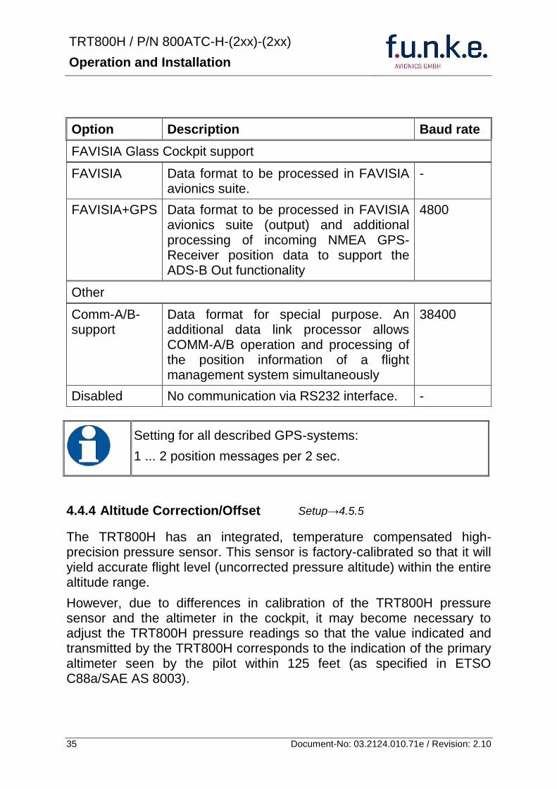
TRT800H PN 800ATC-H-(2xx)-(2xx)
Operation and Installation
36 Document-No 03212401071e Revision 210
The check for correspondence between the primary altimeter and the TRT800H is usually performed every 24 months as part of the aircrafts altimeter checks
Altitude correction is based on setup configurable offset values at five interpolation points ( 2000 8000 18000 25000 and 35000 ft)The offset value itself is limited to a range from -100 to + 100ft at each point (10ft steps)
45 Setup Procedure
Programming of the ICAOA 24-bit Aircraft Address and of the Aircraft Category shall be executed by qualified personnel only
A wrong Aircraft Address or Flight ID may cause serious problems ATC or with ACASTCAS systems
Pilot and owner are responsible for correctly set transponder data
451 Setup Menu Control
In order to access the functions described in the following paragraphs push and hold ID in Standby mode Release ID if desired counter value menu name is displayed to enter the menu The following menu entries are selectable
Count Displayed Name Function
03 FID FID is displayed
48 CHANGE FID Enter FID setup page
913 SHOW SETUP Enter setup summary listed on different pages (no changes possible)
2528 ENTER SETUP Enter transponder general configuration pages
3134 ALTITUDE CORRECTION
Enter altitude correction menu
TRT800H PN 800ATC-H-(2xx)-(2xx)
Operation and Installation
37 Document-No 03212401071e Revision 210
452 Transponder configurationrecord structure
Aircraft related parts of transponder configuration are stored in one out of eight possible records (record=presetting) Each record contains the following information
Aircraft Address (AA 24bit)
Aircraft category (AC)
Flight identification (FID 6-8 numbersletters)
RS-232 Interface setting (eg GPS protocol)
Ground-Switch setting (Installed YesNo)
Speed category (RI) of the respective aircraft
Remote Header setting (Installed YesNo)
User related settings (eg squawk codes display brightness) are stored once in one global record (transponder internally)
453 Transponder configurationrecord handling
At least one record is stored in external memory Up to 8 records can be additional be applied during setup process
If more than one record is applied the active record must be selected out of a list (determined by FID) during start-up of the transponder
Previously applied records can be deleted again by filling FID with zerorsquos only
454 General Setup
Any menu item can be passed by MODE If no changes are made the original settings will remain stored Modification of one menu item does not impact the others No entries will be deleted
TRT800H PN 800ATC-H-(2xx)-(2xx)
Operation and Installation
38 Document-No 03212401071e Revision 210
Step Display (Example)
1 Start-up Transponder
2 Ensure the transponder-mode is bdquoSTBYldquo If necessary change the mode by pressing MODE
3 Press ID A counter is shown at the upper-right corner Hold ID till ldquoENTER SETUPrdquo is displayed
4 After release of ID the first setup menu is displayed
5 helliphellipselect position (^)
rotary knobchange value
MODE
6 With the rotary knob you can select bdquoyesldquo if a Ground Switch is installed if not select ldquonordquo and proceed with step 7
MODE
Record 1
GND Switch YesNo
next
AA EF123456
AC 18
FID ^BCDEFG
next
AA EF123456
AC 18
FID ABCDEFG
next
ENTER SETUP 26
2000 FL 030
STBY 7000
TRT800H PN 800ATC-H-(2xx)-(2xx)
Operation and Installation
39 Document-No 03212401071e Revision 210
Step Display (Example)
7 At this stage the respective speed category shall be selected by using the rotary knob
MODE
8 At this stage a GPS receiver for ADS-B Out can be selected (Selectable by rotary knob)
MODE
9 At this stage remote interface for communication between TRT800H and remote header can be activated (Selectable by rotary knob)
Remote interface must only be activated if a remote header is connected
MODE
10 With ID further Records can now be created and configured as described in the aforementioned steps At start-up of the transponder one of the defined records with all associated configurations need to be selected
MODE
Records ID=Edit Records
EXIT
Record 1
REMOTE Header YesNo
next
Record 1
GPSINTEXT NMEA
next
Record 1
Speed Cat 08-15
next
TRT800H PN 800ATC-H-(2xx)-(2xx)
Operation and Installation
40 Document-No 03212401071e Revision 210
Step Display (Example)
11 You have now left the configuration mode and are back in normal operation
12 Switch off the transponder
13 Switch on the transponder Your ICAO 24-Bit Aircraft Address is now stored
TRT800H V53
FPGA-Vers 102
2000 FL 030
STBY 7000
TRT800H PN 800ATC-H-(2xx)-(2xx)
Operation and Installation
41 Document-No 03212401071e Revision 210
455 Altitude Correction Setup
Altitude correction setup shall be executed by qualified personnel only
Pilot and owner are responsible for correctly set altitude offset values
The usesetting of altitude correction values is only necessary in exceptional cases (see 444 for details)
Altitude correction is based on five interpolation points ( 2000 10000 18000 25000 and 35000 ft)The offset value at each interpolation point can be adjusted in a range from -100 to + 100ft at each point (10ft steps) Offset values set to zero at each interpolation point deactivates altitude correction (defaultfactory setting)
Step Display (Example)
1 Start-up Transponder
2 Ensure the transponder-mode is bdquoSTBYldquo If necessary change the mode by pressing MODE
3 Press ID A counter is shown at the upper-right corner Hold ID till ldquoALTITUDE OFFSETrdquo is displayed
ALTITUDE OFFSET 33
2000 FL 030
STBY 7000
Descriptionrarr444
TRT800H PN 800ATC-H-(2xx)-(2xx)
Operation and Installation
42 Document-No 03212401071e Revision 210
Step Display (Example)
4 After release of ID the first altitude level + corresponding offset value is displayed
5 Change offset value with rotary knob
MODE
6 (9) Repeat last step for another 4 altitude levels 10000ft 18000ft 25000ft 35000ft
MODE
10 You have now left the configuration mode and are back in normal operation
Switch off the transponder
11 Switch on the transponder New altitude offset values will now be used for altitude calculation
Altitude 10000 ft
Offset 0 ft
nextexit
Altitude 2000 ft
Offset 0 ft
next
TRT800H V53
FPGA-Vers 102
2000 FL 030
STBY 7000
Altitude 2000 ft
Offset 0 ft
next
TRT800H PN 800ATC-H-(2xx)-(2xx)
Operation and Installation
43 Document-No 03212401071e Revision 210
5 APPENDIX
51 Technical Data
Compliance CS-ETSO-2C112a
EASA21O269
FAA TSO-C112c
Applicable Documents CS-ETSO-2C112a
FAA TSO-C112c
EUROCAE ED-73C Class 1 Level 2es
RTCA DO-181D Class 1 Level 2es
EUROCAE ED-26
RTCA DO-160D
RTCA DO-178B Software-Level D
Temperature Ranges
Operation -20 degC to +55 degC for 30 min +70degC
Storage -55 degC to +85 degC
Altitude Range le 35 000 ft
Speed Range le 250 kt (TAS)
Shock 6 G Operation
20 G crash safety
Environmental Categories RTCA DO-160D EnvCat [C1Z]CAA[SM]XXXXXXZBAAA[TT]M[B3F3]XXA
Power Supply 138 VDC (10 VDC 16 VDC)
040 A 138 VDC (typ)
070 A 138 VDC (max)
10 W (max)
TRT800H PN 800ATC-H-(2xx)-(2xx)
Operation and Installation
44 Document-No 03212401071e Revision 210
Fuse External 2A-slow-blow fuse
Mounting Panel cut-out d=575 mm
Weight 06 kg (132 lbs)
Receiver Characteristics
Sensitivity
RF input power level resulting in a 90 reply rate
A MTL for ATCRBS and ATCRBSMode S All-Call interrogations -74 dBm plusmn3 dB
B MTL for Mode S interrogations -74 dBm plusmn 3 dB
Reply transmission frequency
1090 plusmn 1 MHz
RF Peak Power Output 21 dBW (126 W) at antenna base (with maximum cable attenuation of 15 dB)
Squitter (ADS-B) transmitted at random intervals uniformly distributed over the range from 08 to 12 seconds full self-verification of data and occurrence
Mode S Elementary Surveillance
ICAO 24-bit Aircraft Address (Hex-Code)
aircraft address as assigned by national aviation authority
FID Flight ID Flight Plan call sign or aircraft registration marking
Capability Report Reports the available data and means by which the transponder can report
Pressure Altitude Up to 35 000 ft in 25 ft increments
Flight Status in-flight on-ground
Mode S Enhanced Surveillance
Level 2es Comm-A Comm-B 56112-Bit-Messages
SI-capability
TRT800H PN 800ATC-H-(2xx)-(2xx)
Operation and Installation
45 Document-No 03212401071e Revision 210
52 Environmental Conditions
Characteristic DOndash160D Section Cat Condition
Temperature Altitude 40
C1
Low ground survival temperature
451 ndash 55degC
Low operating temperature 451 ndash 20degC
High ground survival Temperature
452 + 85degC
High Short-time Operating Temperature
452 + 70degC
High Operating Temperature 453 + 55degC
In-Flight Loss of Cooling 454 Z No auxiliary cooling required
Altitude 461 C1 35 000 ft
Temperature Variation 50 C 2degC change rate minimum per minute
Humidity 60 A
Shock 70 A
6 G operational shocks
20 G Crash Safety
Test Type R in all 6 directions
Vibration 80 S Vibration Curve M
Explosion Proofness 90 X No test required
Water Proofness 100 X No test required
Fluids Susceptibilities 110 X No test required
Sand and Dust 120 X No test required
Fungus Resistance 130 X No test required
Salt Spray 140 X No test required
Magnetic Effect 150 Z Less than 03 m
Power Input (DC) 160 B
Voltage Spike Conducted 170 A
Audio Frequency Conducted Susceptibility
180 A
TRT800H PN 800ATC-H-(2xx)-(2xx)
Operation and Installation
46 Document-No 03212401071e Revision 210
Characteristic DOndash160D Section Cat Condition
Induced Signal Susceptibility 190 A
Radio Frequency Susceptibility
200 TT
Emission of RF Energy 210 M
Lightning Induced Transient Susceptibility
220 B3F3
Lightning Direct Effects 230 X No test required
Icing 240 X No test required
Electrostatic Discharge (ESD) 250 A
53 DO-178B Open Problem Reports
There are no open problem reports for the software of this device
TRT800H PN 800ATC-H-(2xx)-(2xx)
Operation and Installation
47 Document-No 03212401071e Revision 210
Notes
f funke funke means ndash fabrication utilities network know-how engineering
funke AVIONICS GmbH Heinz-Strachowitz-Str 4
DE-86807 Buchloe Germany
phone +49-8241 80066 0
fax +49-8241 80066 99 E-mail
servicefunkeavionicsde wwwfunkeavionicsde
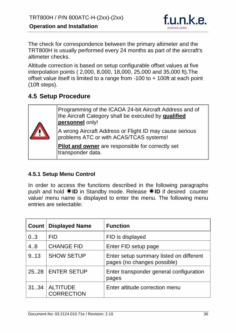
TRT800H PN 800ATC-H-(2xx)-(2xx)
Operation and Installation
37 Document-No 03212401071e Revision 210
452 Transponder configurationrecord structure
Aircraft related parts of transponder configuration are stored in one out of eight possible records (record=presetting) Each record contains the following information
Aircraft Address (AA 24bit)
Aircraft category (AC)
Flight identification (FID 6-8 numbersletters)
RS-232 Interface setting (eg GPS protocol)
Ground-Switch setting (Installed YesNo)
Speed category (RI) of the respective aircraft
Remote Header setting (Installed YesNo)
User related settings (eg squawk codes display brightness) are stored once in one global record (transponder internally)
453 Transponder configurationrecord handling
At least one record is stored in external memory Up to 8 records can be additional be applied during setup process
If more than one record is applied the active record must be selected out of a list (determined by FID) during start-up of the transponder
Previously applied records can be deleted again by filling FID with zerorsquos only
454 General Setup
Any menu item can be passed by MODE If no changes are made the original settings will remain stored Modification of one menu item does not impact the others No entries will be deleted
TRT800H PN 800ATC-H-(2xx)-(2xx)
Operation and Installation
38 Document-No 03212401071e Revision 210
Step Display (Example)
1 Start-up Transponder
2 Ensure the transponder-mode is bdquoSTBYldquo If necessary change the mode by pressing MODE
3 Press ID A counter is shown at the upper-right corner Hold ID till ldquoENTER SETUPrdquo is displayed
4 After release of ID the first setup menu is displayed
5 helliphellipselect position (^)
rotary knobchange value
MODE
6 With the rotary knob you can select bdquoyesldquo if a Ground Switch is installed if not select ldquonordquo and proceed with step 7
MODE
Record 1
GND Switch YesNo
next
AA EF123456
AC 18
FID ^BCDEFG
next
AA EF123456
AC 18
FID ABCDEFG
next
ENTER SETUP 26
2000 FL 030
STBY 7000
TRT800H PN 800ATC-H-(2xx)-(2xx)
Operation and Installation
39 Document-No 03212401071e Revision 210
Step Display (Example)
7 At this stage the respective speed category shall be selected by using the rotary knob
MODE
8 At this stage a GPS receiver for ADS-B Out can be selected (Selectable by rotary knob)
MODE
9 At this stage remote interface for communication between TRT800H and remote header can be activated (Selectable by rotary knob)
Remote interface must only be activated if a remote header is connected
MODE
10 With ID further Records can now be created and configured as described in the aforementioned steps At start-up of the transponder one of the defined records with all associated configurations need to be selected
MODE
Records ID=Edit Records
EXIT
Record 1
REMOTE Header YesNo
next
Record 1
GPSINTEXT NMEA
next
Record 1
Speed Cat 08-15
next
TRT800H PN 800ATC-H-(2xx)-(2xx)
Operation and Installation
40 Document-No 03212401071e Revision 210
Step Display (Example)
11 You have now left the configuration mode and are back in normal operation
12 Switch off the transponder
13 Switch on the transponder Your ICAO 24-Bit Aircraft Address is now stored
TRT800H V53
FPGA-Vers 102
2000 FL 030
STBY 7000
TRT800H PN 800ATC-H-(2xx)-(2xx)
Operation and Installation
41 Document-No 03212401071e Revision 210
455 Altitude Correction Setup
Altitude correction setup shall be executed by qualified personnel only
Pilot and owner are responsible for correctly set altitude offset values
The usesetting of altitude correction values is only necessary in exceptional cases (see 444 for details)
Altitude correction is based on five interpolation points ( 2000 10000 18000 25000 and 35000 ft)The offset value at each interpolation point can be adjusted in a range from -100 to + 100ft at each point (10ft steps) Offset values set to zero at each interpolation point deactivates altitude correction (defaultfactory setting)
Step Display (Example)
1 Start-up Transponder
2 Ensure the transponder-mode is bdquoSTBYldquo If necessary change the mode by pressing MODE
3 Press ID A counter is shown at the upper-right corner Hold ID till ldquoALTITUDE OFFSETrdquo is displayed
ALTITUDE OFFSET 33
2000 FL 030
STBY 7000
Descriptionrarr444
TRT800H PN 800ATC-H-(2xx)-(2xx)
Operation and Installation
42 Document-No 03212401071e Revision 210
Step Display (Example)
4 After release of ID the first altitude level + corresponding offset value is displayed
5 Change offset value with rotary knob
MODE
6 (9) Repeat last step for another 4 altitude levels 10000ft 18000ft 25000ft 35000ft
MODE
10 You have now left the configuration mode and are back in normal operation
Switch off the transponder
11 Switch on the transponder New altitude offset values will now be used for altitude calculation
Altitude 10000 ft
Offset 0 ft
nextexit
Altitude 2000 ft
Offset 0 ft
next
TRT800H V53
FPGA-Vers 102
2000 FL 030
STBY 7000
Altitude 2000 ft
Offset 0 ft
next
TRT800H PN 800ATC-H-(2xx)-(2xx)
Operation and Installation
43 Document-No 03212401071e Revision 210
5 APPENDIX
51 Technical Data
Compliance CS-ETSO-2C112a
EASA21O269
FAA TSO-C112c
Applicable Documents CS-ETSO-2C112a
FAA TSO-C112c
EUROCAE ED-73C Class 1 Level 2es
RTCA DO-181D Class 1 Level 2es
EUROCAE ED-26
RTCA DO-160D
RTCA DO-178B Software-Level D
Temperature Ranges
Operation -20 degC to +55 degC for 30 min +70degC
Storage -55 degC to +85 degC
Altitude Range le 35 000 ft
Speed Range le 250 kt (TAS)
Shock 6 G Operation
20 G crash safety
Environmental Categories RTCA DO-160D EnvCat [C1Z]CAA[SM]XXXXXXZBAAA[TT]M[B3F3]XXA
Power Supply 138 VDC (10 VDC 16 VDC)
040 A 138 VDC (typ)
070 A 138 VDC (max)
10 W (max)
TRT800H PN 800ATC-H-(2xx)-(2xx)
Operation and Installation
44 Document-No 03212401071e Revision 210
Fuse External 2A-slow-blow fuse
Mounting Panel cut-out d=575 mm
Weight 06 kg (132 lbs)
Receiver Characteristics
Sensitivity
RF input power level resulting in a 90 reply rate
A MTL for ATCRBS and ATCRBSMode S All-Call interrogations -74 dBm plusmn3 dB
B MTL for Mode S interrogations -74 dBm plusmn 3 dB
Reply transmission frequency
1090 plusmn 1 MHz
RF Peak Power Output 21 dBW (126 W) at antenna base (with maximum cable attenuation of 15 dB)
Squitter (ADS-B) transmitted at random intervals uniformly distributed over the range from 08 to 12 seconds full self-verification of data and occurrence
Mode S Elementary Surveillance
ICAO 24-bit Aircraft Address (Hex-Code)
aircraft address as assigned by national aviation authority
FID Flight ID Flight Plan call sign or aircraft registration marking
Capability Report Reports the available data and means by which the transponder can report
Pressure Altitude Up to 35 000 ft in 25 ft increments
Flight Status in-flight on-ground
Mode S Enhanced Surveillance
Level 2es Comm-A Comm-B 56112-Bit-Messages
SI-capability
TRT800H PN 800ATC-H-(2xx)-(2xx)
Operation and Installation
45 Document-No 03212401071e Revision 210
52 Environmental Conditions
Characteristic DOndash160D Section Cat Condition
Temperature Altitude 40
C1
Low ground survival temperature
451 ndash 55degC
Low operating temperature 451 ndash 20degC
High ground survival Temperature
452 + 85degC
High Short-time Operating Temperature
452 + 70degC
High Operating Temperature 453 + 55degC
In-Flight Loss of Cooling 454 Z No auxiliary cooling required
Altitude 461 C1 35 000 ft
Temperature Variation 50 C 2degC change rate minimum per minute
Humidity 60 A
Shock 70 A
6 G operational shocks
20 G Crash Safety
Test Type R in all 6 directions
Vibration 80 S Vibration Curve M
Explosion Proofness 90 X No test required
Water Proofness 100 X No test required
Fluids Susceptibilities 110 X No test required
Sand and Dust 120 X No test required
Fungus Resistance 130 X No test required
Salt Spray 140 X No test required
Magnetic Effect 150 Z Less than 03 m
Power Input (DC) 160 B
Voltage Spike Conducted 170 A
Audio Frequency Conducted Susceptibility
180 A
TRT800H PN 800ATC-H-(2xx)-(2xx)
Operation and Installation
46 Document-No 03212401071e Revision 210
Characteristic DOndash160D Section Cat Condition
Induced Signal Susceptibility 190 A
Radio Frequency Susceptibility
200 TT
Emission of RF Energy 210 M
Lightning Induced Transient Susceptibility
220 B3F3
Lightning Direct Effects 230 X No test required
Icing 240 X No test required
Electrostatic Discharge (ESD) 250 A
53 DO-178B Open Problem Reports
There are no open problem reports for the software of this device
TRT800H PN 800ATC-H-(2xx)-(2xx)
Operation and Installation
47 Document-No 03212401071e Revision 210
Notes
f funke funke means ndash fabrication utilities network know-how engineering
funke AVIONICS GmbH Heinz-Strachowitz-Str 4
DE-86807 Buchloe Germany
phone +49-8241 80066 0
fax +49-8241 80066 99 E-mail
servicefunkeavionicsde wwwfunkeavionicsde
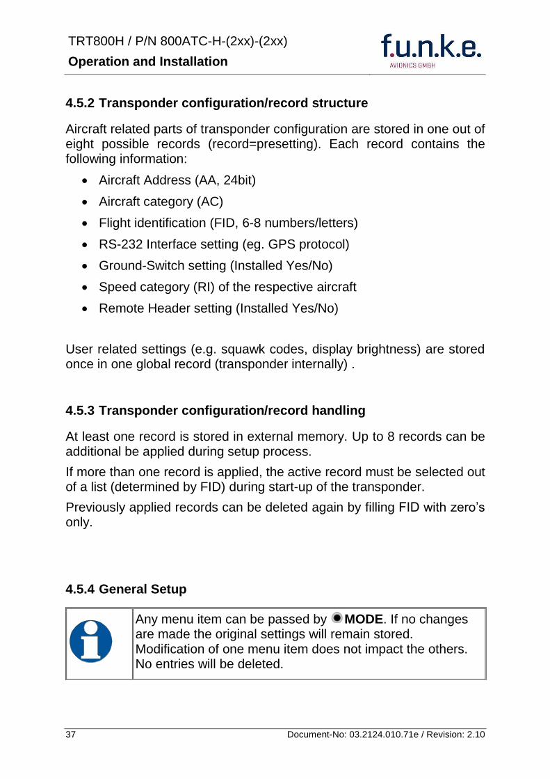
TRT800H PN 800ATC-H-(2xx)-(2xx)
Operation and Installation
38 Document-No 03212401071e Revision 210
Step Display (Example)
1 Start-up Transponder
2 Ensure the transponder-mode is bdquoSTBYldquo If necessary change the mode by pressing MODE
3 Press ID A counter is shown at the upper-right corner Hold ID till ldquoENTER SETUPrdquo is displayed
4 After release of ID the first setup menu is displayed
5 helliphellipselect position (^)
rotary knobchange value
MODE
6 With the rotary knob you can select bdquoyesldquo if a Ground Switch is installed if not select ldquonordquo and proceed with step 7
MODE
Record 1
GND Switch YesNo
next
AA EF123456
AC 18
FID ^BCDEFG
next
AA EF123456
AC 18
FID ABCDEFG
next
ENTER SETUP 26
2000 FL 030
STBY 7000
TRT800H PN 800ATC-H-(2xx)-(2xx)
Operation and Installation
39 Document-No 03212401071e Revision 210
Step Display (Example)
7 At this stage the respective speed category shall be selected by using the rotary knob
MODE
8 At this stage a GPS receiver for ADS-B Out can be selected (Selectable by rotary knob)
MODE
9 At this stage remote interface for communication between TRT800H and remote header can be activated (Selectable by rotary knob)
Remote interface must only be activated if a remote header is connected
MODE
10 With ID further Records can now be created and configured as described in the aforementioned steps At start-up of the transponder one of the defined records with all associated configurations need to be selected
MODE
Records ID=Edit Records
EXIT
Record 1
REMOTE Header YesNo
next
Record 1
GPSINTEXT NMEA
next
Record 1
Speed Cat 08-15
next
TRT800H PN 800ATC-H-(2xx)-(2xx)
Operation and Installation
40 Document-No 03212401071e Revision 210
Step Display (Example)
11 You have now left the configuration mode and are back in normal operation
12 Switch off the transponder
13 Switch on the transponder Your ICAO 24-Bit Aircraft Address is now stored
TRT800H V53
FPGA-Vers 102
2000 FL 030
STBY 7000
TRT800H PN 800ATC-H-(2xx)-(2xx)
Operation and Installation
41 Document-No 03212401071e Revision 210
455 Altitude Correction Setup
Altitude correction setup shall be executed by qualified personnel only
Pilot and owner are responsible for correctly set altitude offset values
The usesetting of altitude correction values is only necessary in exceptional cases (see 444 for details)
Altitude correction is based on five interpolation points ( 2000 10000 18000 25000 and 35000 ft)The offset value at each interpolation point can be adjusted in a range from -100 to + 100ft at each point (10ft steps) Offset values set to zero at each interpolation point deactivates altitude correction (defaultfactory setting)
Step Display (Example)
1 Start-up Transponder
2 Ensure the transponder-mode is bdquoSTBYldquo If necessary change the mode by pressing MODE
3 Press ID A counter is shown at the upper-right corner Hold ID till ldquoALTITUDE OFFSETrdquo is displayed
ALTITUDE OFFSET 33
2000 FL 030
STBY 7000
Descriptionrarr444
TRT800H PN 800ATC-H-(2xx)-(2xx)
Operation and Installation
42 Document-No 03212401071e Revision 210
Step Display (Example)
4 After release of ID the first altitude level + corresponding offset value is displayed
5 Change offset value with rotary knob
MODE
6 (9) Repeat last step for another 4 altitude levels 10000ft 18000ft 25000ft 35000ft
MODE
10 You have now left the configuration mode and are back in normal operation
Switch off the transponder
11 Switch on the transponder New altitude offset values will now be used for altitude calculation
Altitude 10000 ft
Offset 0 ft
nextexit
Altitude 2000 ft
Offset 0 ft
next
TRT800H V53
FPGA-Vers 102
2000 FL 030
STBY 7000
Altitude 2000 ft
Offset 0 ft
next
TRT800H PN 800ATC-H-(2xx)-(2xx)
Operation and Installation
43 Document-No 03212401071e Revision 210
5 APPENDIX
51 Technical Data
Compliance CS-ETSO-2C112a
EASA21O269
FAA TSO-C112c
Applicable Documents CS-ETSO-2C112a
FAA TSO-C112c
EUROCAE ED-73C Class 1 Level 2es
RTCA DO-181D Class 1 Level 2es
EUROCAE ED-26
RTCA DO-160D
RTCA DO-178B Software-Level D
Temperature Ranges
Operation -20 degC to +55 degC for 30 min +70degC
Storage -55 degC to +85 degC
Altitude Range le 35 000 ft
Speed Range le 250 kt (TAS)
Shock 6 G Operation
20 G crash safety
Environmental Categories RTCA DO-160D EnvCat [C1Z]CAA[SM]XXXXXXZBAAA[TT]M[B3F3]XXA
Power Supply 138 VDC (10 VDC 16 VDC)
040 A 138 VDC (typ)
070 A 138 VDC (max)
10 W (max)
TRT800H PN 800ATC-H-(2xx)-(2xx)
Operation and Installation
44 Document-No 03212401071e Revision 210
Fuse External 2A-slow-blow fuse
Mounting Panel cut-out d=575 mm
Weight 06 kg (132 lbs)
Receiver Characteristics
Sensitivity
RF input power level resulting in a 90 reply rate
A MTL for ATCRBS and ATCRBSMode S All-Call interrogations -74 dBm plusmn3 dB
B MTL for Mode S interrogations -74 dBm plusmn 3 dB
Reply transmission frequency
1090 plusmn 1 MHz
RF Peak Power Output 21 dBW (126 W) at antenna base (with maximum cable attenuation of 15 dB)
Squitter (ADS-B) transmitted at random intervals uniformly distributed over the range from 08 to 12 seconds full self-verification of data and occurrence
Mode S Elementary Surveillance
ICAO 24-bit Aircraft Address (Hex-Code)
aircraft address as assigned by national aviation authority
FID Flight ID Flight Plan call sign or aircraft registration marking
Capability Report Reports the available data and means by which the transponder can report
Pressure Altitude Up to 35 000 ft in 25 ft increments
Flight Status in-flight on-ground
Mode S Enhanced Surveillance
Level 2es Comm-A Comm-B 56112-Bit-Messages
SI-capability
TRT800H PN 800ATC-H-(2xx)-(2xx)
Operation and Installation
45 Document-No 03212401071e Revision 210
52 Environmental Conditions
Characteristic DOndash160D Section Cat Condition
Temperature Altitude 40
C1
Low ground survival temperature
451 ndash 55degC
Low operating temperature 451 ndash 20degC
High ground survival Temperature
452 + 85degC
High Short-time Operating Temperature
452 + 70degC
High Operating Temperature 453 + 55degC
In-Flight Loss of Cooling 454 Z No auxiliary cooling required
Altitude 461 C1 35 000 ft
Temperature Variation 50 C 2degC change rate minimum per minute
Humidity 60 A
Shock 70 A
6 G operational shocks
20 G Crash Safety
Test Type R in all 6 directions
Vibration 80 S Vibration Curve M
Explosion Proofness 90 X No test required
Water Proofness 100 X No test required
Fluids Susceptibilities 110 X No test required
Sand and Dust 120 X No test required
Fungus Resistance 130 X No test required
Salt Spray 140 X No test required
Magnetic Effect 150 Z Less than 03 m
Power Input (DC) 160 B
Voltage Spike Conducted 170 A
Audio Frequency Conducted Susceptibility
180 A
TRT800H PN 800ATC-H-(2xx)-(2xx)
Operation and Installation
46 Document-No 03212401071e Revision 210
Characteristic DOndash160D Section Cat Condition
Induced Signal Susceptibility 190 A
Radio Frequency Susceptibility
200 TT
Emission of RF Energy 210 M
Lightning Induced Transient Susceptibility
220 B3F3
Lightning Direct Effects 230 X No test required
Icing 240 X No test required
Electrostatic Discharge (ESD) 250 A
53 DO-178B Open Problem Reports
There are no open problem reports for the software of this device
TRT800H PN 800ATC-H-(2xx)-(2xx)
Operation and Installation
47 Document-No 03212401071e Revision 210
Notes
f funke funke means ndash fabrication utilities network know-how engineering
funke AVIONICS GmbH Heinz-Strachowitz-Str 4
DE-86807 Buchloe Germany
phone +49-8241 80066 0
fax +49-8241 80066 99 E-mail
servicefunkeavionicsde wwwfunkeavionicsde
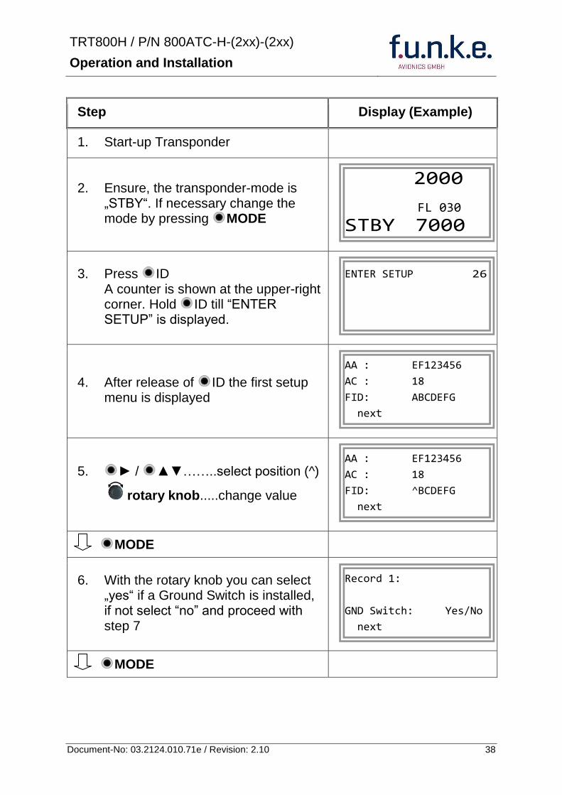
TRT800H PN 800ATC-H-(2xx)-(2xx)
Operation and Installation
39 Document-No 03212401071e Revision 210
Step Display (Example)
7 At this stage the respective speed category shall be selected by using the rotary knob
MODE
8 At this stage a GPS receiver for ADS-B Out can be selected (Selectable by rotary knob)
MODE
9 At this stage remote interface for communication between TRT800H and remote header can be activated (Selectable by rotary knob)
Remote interface must only be activated if a remote header is connected
MODE
10 With ID further Records can now be created and configured as described in the aforementioned steps At start-up of the transponder one of the defined records with all associated configurations need to be selected
MODE
Records ID=Edit Records
EXIT
Record 1
REMOTE Header YesNo
next
Record 1
GPSINTEXT NMEA
next
Record 1
Speed Cat 08-15
next
TRT800H PN 800ATC-H-(2xx)-(2xx)
Operation and Installation
40 Document-No 03212401071e Revision 210
Step Display (Example)
11 You have now left the configuration mode and are back in normal operation
12 Switch off the transponder
13 Switch on the transponder Your ICAO 24-Bit Aircraft Address is now stored
TRT800H V53
FPGA-Vers 102
2000 FL 030
STBY 7000
TRT800H PN 800ATC-H-(2xx)-(2xx)
Operation and Installation
41 Document-No 03212401071e Revision 210
455 Altitude Correction Setup
Altitude correction setup shall be executed by qualified personnel only
Pilot and owner are responsible for correctly set altitude offset values
The usesetting of altitude correction values is only necessary in exceptional cases (see 444 for details)
Altitude correction is based on five interpolation points ( 2000 10000 18000 25000 and 35000 ft)The offset value at each interpolation point can be adjusted in a range from -100 to + 100ft at each point (10ft steps) Offset values set to zero at each interpolation point deactivates altitude correction (defaultfactory setting)
Step Display (Example)
1 Start-up Transponder
2 Ensure the transponder-mode is bdquoSTBYldquo If necessary change the mode by pressing MODE
3 Press ID A counter is shown at the upper-right corner Hold ID till ldquoALTITUDE OFFSETrdquo is displayed
ALTITUDE OFFSET 33
2000 FL 030
STBY 7000
Descriptionrarr444
TRT800H PN 800ATC-H-(2xx)-(2xx)
Operation and Installation
42 Document-No 03212401071e Revision 210
Step Display (Example)
4 After release of ID the first altitude level + corresponding offset value is displayed
5 Change offset value with rotary knob
MODE
6 (9) Repeat last step for another 4 altitude levels 10000ft 18000ft 25000ft 35000ft
MODE
10 You have now left the configuration mode and are back in normal operation
Switch off the transponder
11 Switch on the transponder New altitude offset values will now be used for altitude calculation
Altitude 10000 ft
Offset 0 ft
nextexit
Altitude 2000 ft
Offset 0 ft
next
TRT800H V53
FPGA-Vers 102
2000 FL 030
STBY 7000
Altitude 2000 ft
Offset 0 ft
next
TRT800H PN 800ATC-H-(2xx)-(2xx)
Operation and Installation
43 Document-No 03212401071e Revision 210
5 APPENDIX
51 Technical Data
Compliance CS-ETSO-2C112a
EASA21O269
FAA TSO-C112c
Applicable Documents CS-ETSO-2C112a
FAA TSO-C112c
EUROCAE ED-73C Class 1 Level 2es
RTCA DO-181D Class 1 Level 2es
EUROCAE ED-26
RTCA DO-160D
RTCA DO-178B Software-Level D
Temperature Ranges
Operation -20 degC to +55 degC for 30 min +70degC
Storage -55 degC to +85 degC
Altitude Range le 35 000 ft
Speed Range le 250 kt (TAS)
Shock 6 G Operation
20 G crash safety
Environmental Categories RTCA DO-160D EnvCat [C1Z]CAA[SM]XXXXXXZBAAA[TT]M[B3F3]XXA
Power Supply 138 VDC (10 VDC 16 VDC)
040 A 138 VDC (typ)
070 A 138 VDC (max)
10 W (max)
TRT800H PN 800ATC-H-(2xx)-(2xx)
Operation and Installation
44 Document-No 03212401071e Revision 210
Fuse External 2A-slow-blow fuse
Mounting Panel cut-out d=575 mm
Weight 06 kg (132 lbs)
Receiver Characteristics
Sensitivity
RF input power level resulting in a 90 reply rate
A MTL for ATCRBS and ATCRBSMode S All-Call interrogations -74 dBm plusmn3 dB
B MTL for Mode S interrogations -74 dBm plusmn 3 dB
Reply transmission frequency
1090 plusmn 1 MHz
RF Peak Power Output 21 dBW (126 W) at antenna base (with maximum cable attenuation of 15 dB)
Squitter (ADS-B) transmitted at random intervals uniformly distributed over the range from 08 to 12 seconds full self-verification of data and occurrence
Mode S Elementary Surveillance
ICAO 24-bit Aircraft Address (Hex-Code)
aircraft address as assigned by national aviation authority
FID Flight ID Flight Plan call sign or aircraft registration marking
Capability Report Reports the available data and means by which the transponder can report
Pressure Altitude Up to 35 000 ft in 25 ft increments
Flight Status in-flight on-ground
Mode S Enhanced Surveillance
Level 2es Comm-A Comm-B 56112-Bit-Messages
SI-capability
TRT800H PN 800ATC-H-(2xx)-(2xx)
Operation and Installation
45 Document-No 03212401071e Revision 210
52 Environmental Conditions
Characteristic DOndash160D Section Cat Condition
Temperature Altitude 40
C1
Low ground survival temperature
451 ndash 55degC
Low operating temperature 451 ndash 20degC
High ground survival Temperature
452 + 85degC
High Short-time Operating Temperature
452 + 70degC
High Operating Temperature 453 + 55degC
In-Flight Loss of Cooling 454 Z No auxiliary cooling required
Altitude 461 C1 35 000 ft
Temperature Variation 50 C 2degC change rate minimum per minute
Humidity 60 A
Shock 70 A
6 G operational shocks
20 G Crash Safety
Test Type R in all 6 directions
Vibration 80 S Vibration Curve M
Explosion Proofness 90 X No test required
Water Proofness 100 X No test required
Fluids Susceptibilities 110 X No test required
Sand and Dust 120 X No test required
Fungus Resistance 130 X No test required
Salt Spray 140 X No test required
Magnetic Effect 150 Z Less than 03 m
Power Input (DC) 160 B
Voltage Spike Conducted 170 A
Audio Frequency Conducted Susceptibility
180 A
TRT800H PN 800ATC-H-(2xx)-(2xx)
Operation and Installation
46 Document-No 03212401071e Revision 210
Characteristic DOndash160D Section Cat Condition
Induced Signal Susceptibility 190 A
Radio Frequency Susceptibility
200 TT
Emission of RF Energy 210 M
Lightning Induced Transient Susceptibility
220 B3F3
Lightning Direct Effects 230 X No test required
Icing 240 X No test required
Electrostatic Discharge (ESD) 250 A
53 DO-178B Open Problem Reports
There are no open problem reports for the software of this device
TRT800H PN 800ATC-H-(2xx)-(2xx)
Operation and Installation
47 Document-No 03212401071e Revision 210
Notes
f funke funke means ndash fabrication utilities network know-how engineering
funke AVIONICS GmbH Heinz-Strachowitz-Str 4
DE-86807 Buchloe Germany
phone +49-8241 80066 0
fax +49-8241 80066 99 E-mail
servicefunkeavionicsde wwwfunkeavionicsde
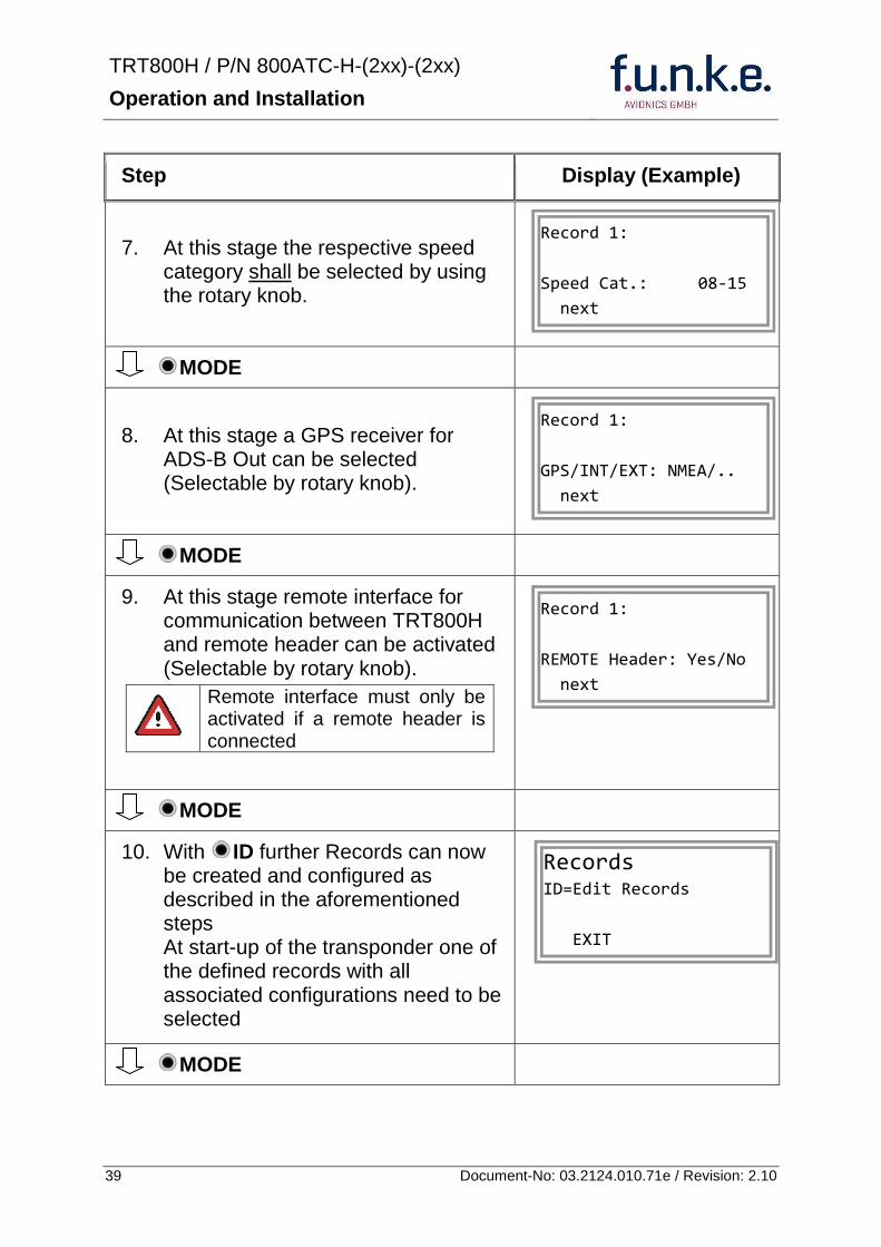
TRT800H PN 800ATC-H-(2xx)-(2xx)
Operation and Installation
41 Document-No 03212401071e Revision 210
455 Altitude Correction Setup
Altitude correction setup shall be executed by qualified personnel only
Pilot and owner are responsible for correctly set altitude offset values
The usesetting of altitude correction values is only necessary in exceptional cases (see 444 for details)
Altitude correction is based on five interpolation points ( 2000 10000 18000 25000 and 35000 ft)The offset value at each interpolation point can be adjusted in a range from -100 to + 100ft at each point (10ft steps) Offset values set to zero at each interpolation point deactivates altitude correction (defaultfactory setting)
Step Display (Example)
1 Start-up Transponder
2 Ensure the transponder-mode is bdquoSTBYldquo If necessary change the mode by pressing MODE
3 Press ID A counter is shown at the upper-right corner Hold ID till ldquoALTITUDE OFFSETrdquo is displayed
ALTITUDE OFFSET 33
2000 FL 030
STBY 7000
Descriptionrarr444
TRT800H PN 800ATC-H-(2xx)-(2xx)
Operation and Installation
42 Document-No 03212401071e Revision 210
Step Display (Example)
4 After release of ID the first altitude level + corresponding offset value is displayed
5 Change offset value with rotary knob
MODE
6 (9) Repeat last step for another 4 altitude levels 10000ft 18000ft 25000ft 35000ft
MODE
10 You have now left the configuration mode and are back in normal operation
Switch off the transponder
11 Switch on the transponder New altitude offset values will now be used for altitude calculation
Altitude 10000 ft
Offset 0 ft
nextexit
Altitude 2000 ft
Offset 0 ft
next
TRT800H V53
FPGA-Vers 102
2000 FL 030
STBY 7000
Altitude 2000 ft
Offset 0 ft
next
TRT800H PN 800ATC-H-(2xx)-(2xx)
Operation and Installation
43 Document-No 03212401071e Revision 210
5 APPENDIX
51 Technical Data
Compliance CS-ETSO-2C112a
EASA21O269
FAA TSO-C112c
Applicable Documents CS-ETSO-2C112a
FAA TSO-C112c
EUROCAE ED-73C Class 1 Level 2es
RTCA DO-181D Class 1 Level 2es
EUROCAE ED-26
RTCA DO-160D
RTCA DO-178B Software-Level D
Temperature Ranges
Operation -20 degC to +55 degC for 30 min +70degC
Storage -55 degC to +85 degC
Altitude Range le 35 000 ft
Speed Range le 250 kt (TAS)
Shock 6 G Operation
20 G crash safety
Environmental Categories RTCA DO-160D EnvCat [C1Z]CAA[SM]XXXXXXZBAAA[TT]M[B3F3]XXA
Power Supply 138 VDC (10 VDC 16 VDC)
040 A 138 VDC (typ)
070 A 138 VDC (max)
10 W (max)
TRT800H PN 800ATC-H-(2xx)-(2xx)
Operation and Installation
44 Document-No 03212401071e Revision 210
Fuse External 2A-slow-blow fuse
Mounting Panel cut-out d=575 mm
Weight 06 kg (132 lbs)
Receiver Characteristics
Sensitivity
RF input power level resulting in a 90 reply rate
A MTL for ATCRBS and ATCRBSMode S All-Call interrogations -74 dBm plusmn3 dB
B MTL for Mode S interrogations -74 dBm plusmn 3 dB
Reply transmission frequency
1090 plusmn 1 MHz
RF Peak Power Output 21 dBW (126 W) at antenna base (with maximum cable attenuation of 15 dB)
Squitter (ADS-B) transmitted at random intervals uniformly distributed over the range from 08 to 12 seconds full self-verification of data and occurrence
Mode S Elementary Surveillance
ICAO 24-bit Aircraft Address (Hex-Code)
aircraft address as assigned by national aviation authority
FID Flight ID Flight Plan call sign or aircraft registration marking
Capability Report Reports the available data and means by which the transponder can report
Pressure Altitude Up to 35 000 ft in 25 ft increments
Flight Status in-flight on-ground
Mode S Enhanced Surveillance
Level 2es Comm-A Comm-B 56112-Bit-Messages
SI-capability
TRT800H PN 800ATC-H-(2xx)-(2xx)
Operation and Installation
45 Document-No 03212401071e Revision 210
52 Environmental Conditions
Characteristic DOndash160D Section Cat Condition
Temperature Altitude 40
C1
Low ground survival temperature
451 ndash 55degC
Low operating temperature 451 ndash 20degC
High ground survival Temperature
452 + 85degC
High Short-time Operating Temperature
452 + 70degC
High Operating Temperature 453 + 55degC
In-Flight Loss of Cooling 454 Z No auxiliary cooling required
Altitude 461 C1 35 000 ft
Temperature Variation 50 C 2degC change rate minimum per minute
Humidity 60 A
Shock 70 A
6 G operational shocks
20 G Crash Safety
Test Type R in all 6 directions
Vibration 80 S Vibration Curve M
Explosion Proofness 90 X No test required
Water Proofness 100 X No test required
Fluids Susceptibilities 110 X No test required
Sand and Dust 120 X No test required
Fungus Resistance 130 X No test required
Salt Spray 140 X No test required
Magnetic Effect 150 Z Less than 03 m
Power Input (DC) 160 B
Voltage Spike Conducted 170 A
Audio Frequency Conducted Susceptibility
180 A
TRT800H PN 800ATC-H-(2xx)-(2xx)
Operation and Installation
46 Document-No 03212401071e Revision 210
Characteristic DOndash160D Section Cat Condition
Induced Signal Susceptibility 190 A
Radio Frequency Susceptibility
200 TT
Emission of RF Energy 210 M
Lightning Induced Transient Susceptibility
220 B3F3
Lightning Direct Effects 230 X No test required
Icing 240 X No test required
Electrostatic Discharge (ESD) 250 A
53 DO-178B Open Problem Reports
There are no open problem reports for the software of this device
TRT800H PN 800ATC-H-(2xx)-(2xx)
Operation and Installation
47 Document-No 03212401071e Revision 210
Notes
f funke funke means ndash fabrication utilities network know-how engineering
funke AVIONICS GmbH Heinz-Strachowitz-Str 4
DE-86807 Buchloe Germany
phone +49-8241 80066 0
fax +49-8241 80066 99 E-mail
servicefunkeavionicsde wwwfunkeavionicsde
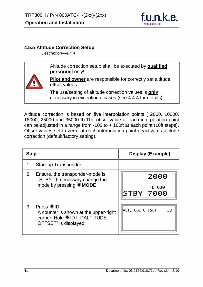
TRT800H PN 800ATC-H-(2xx)-(2xx)
Operation and Installation
42 Document-No 03212401071e Revision 210
Step Display (Example)
4 After release of ID the first altitude level + corresponding offset value is displayed
5 Change offset value with rotary knob
MODE
6 (9) Repeat last step for another 4 altitude levels 10000ft 18000ft 25000ft 35000ft
MODE
10 You have now left the configuration mode and are back in normal operation
Switch off the transponder
11 Switch on the transponder New altitude offset values will now be used for altitude calculation
Altitude 10000 ft
Offset 0 ft
nextexit
Altitude 2000 ft
Offset 0 ft
next
TRT800H V53
FPGA-Vers 102
2000 FL 030
STBY 7000
Altitude 2000 ft
Offset 0 ft
next
TRT800H PN 800ATC-H-(2xx)-(2xx)
Operation and Installation
43 Document-No 03212401071e Revision 210
5 APPENDIX
51 Technical Data
Compliance CS-ETSO-2C112a
EASA21O269
FAA TSO-C112c
Applicable Documents CS-ETSO-2C112a
FAA TSO-C112c
EUROCAE ED-73C Class 1 Level 2es
RTCA DO-181D Class 1 Level 2es
EUROCAE ED-26
RTCA DO-160D
RTCA DO-178B Software-Level D
Temperature Ranges
Operation -20 degC to +55 degC for 30 min +70degC
Storage -55 degC to +85 degC
Altitude Range le 35 000 ft
Speed Range le 250 kt (TAS)
Shock 6 G Operation
20 G crash safety
Environmental Categories RTCA DO-160D EnvCat [C1Z]CAA[SM]XXXXXXZBAAA[TT]M[B3F3]XXA
Power Supply 138 VDC (10 VDC 16 VDC)
040 A 138 VDC (typ)
070 A 138 VDC (max)
10 W (max)
TRT800H PN 800ATC-H-(2xx)-(2xx)
Operation and Installation
44 Document-No 03212401071e Revision 210
Fuse External 2A-slow-blow fuse
Mounting Panel cut-out d=575 mm
Weight 06 kg (132 lbs)
Receiver Characteristics
Sensitivity
RF input power level resulting in a 90 reply rate
A MTL for ATCRBS and ATCRBSMode S All-Call interrogations -74 dBm plusmn3 dB
B MTL for Mode S interrogations -74 dBm plusmn 3 dB
Reply transmission frequency
1090 plusmn 1 MHz
RF Peak Power Output 21 dBW (126 W) at antenna base (with maximum cable attenuation of 15 dB)
Squitter (ADS-B) transmitted at random intervals uniformly distributed over the range from 08 to 12 seconds full self-verification of data and occurrence
Mode S Elementary Surveillance
ICAO 24-bit Aircraft Address (Hex-Code)
aircraft address as assigned by national aviation authority
FID Flight ID Flight Plan call sign or aircraft registration marking
Capability Report Reports the available data and means by which the transponder can report
Pressure Altitude Up to 35 000 ft in 25 ft increments
Flight Status in-flight on-ground
Mode S Enhanced Surveillance
Level 2es Comm-A Comm-B 56112-Bit-Messages
SI-capability
TRT800H PN 800ATC-H-(2xx)-(2xx)
Operation and Installation
45 Document-No 03212401071e Revision 210
52 Environmental Conditions
Characteristic DOndash160D Section Cat Condition
Temperature Altitude 40
C1
Low ground survival temperature
451 ndash 55degC
Low operating temperature 451 ndash 20degC
High ground survival Temperature
452 + 85degC
High Short-time Operating Temperature
452 + 70degC
High Operating Temperature 453 + 55degC
In-Flight Loss of Cooling 454 Z No auxiliary cooling required
Altitude 461 C1 35 000 ft
Temperature Variation 50 C 2degC change rate minimum per minute
Humidity 60 A
Shock 70 A
6 G operational shocks
20 G Crash Safety
Test Type R in all 6 directions
Vibration 80 S Vibration Curve M
Explosion Proofness 90 X No test required
Water Proofness 100 X No test required
Fluids Susceptibilities 110 X No test required
Sand and Dust 120 X No test required
Fungus Resistance 130 X No test required
Salt Spray 140 X No test required
Magnetic Effect 150 Z Less than 03 m
Power Input (DC) 160 B
Voltage Spike Conducted 170 A
Audio Frequency Conducted Susceptibility
180 A
TRT800H PN 800ATC-H-(2xx)-(2xx)
Operation and Installation
46 Document-No 03212401071e Revision 210
Characteristic DOndash160D Section Cat Condition
Induced Signal Susceptibility 190 A
Radio Frequency Susceptibility
200 TT
Emission of RF Energy 210 M
Lightning Induced Transient Susceptibility
220 B3F3
Lightning Direct Effects 230 X No test required
Icing 240 X No test required
Electrostatic Discharge (ESD) 250 A
53 DO-178B Open Problem Reports
There are no open problem reports for the software of this device
TRT800H PN 800ATC-H-(2xx)-(2xx)
Operation and Installation
47 Document-No 03212401071e Revision 210
Notes
f funke funke means ndash fabrication utilities network know-how engineering
funke AVIONICS GmbH Heinz-Strachowitz-Str 4
DE-86807 Buchloe Germany
phone +49-8241 80066 0
fax +49-8241 80066 99 E-mail
servicefunkeavionicsde wwwfunkeavionicsde
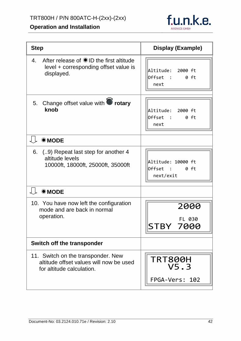
TRT800H PN 800ATC-H-(2xx)-(2xx)
Operation and Installation
43 Document-No 03212401071e Revision 210
5 APPENDIX
51 Technical Data
Compliance CS-ETSO-2C112a
EASA21O269
FAA TSO-C112c
Applicable Documents CS-ETSO-2C112a
FAA TSO-C112c
EUROCAE ED-73C Class 1 Level 2es
RTCA DO-181D Class 1 Level 2es
EUROCAE ED-26
RTCA DO-160D
RTCA DO-178B Software-Level D
Temperature Ranges
Operation -20 degC to +55 degC for 30 min +70degC
Storage -55 degC to +85 degC
Altitude Range le 35 000 ft
Speed Range le 250 kt (TAS)
Shock 6 G Operation
20 G crash safety
Environmental Categories RTCA DO-160D EnvCat [C1Z]CAA[SM]XXXXXXZBAAA[TT]M[B3F3]XXA
Power Supply 138 VDC (10 VDC 16 VDC)
040 A 138 VDC (typ)
070 A 138 VDC (max)
10 W (max)
TRT800H PN 800ATC-H-(2xx)-(2xx)
Operation and Installation
44 Document-No 03212401071e Revision 210
Fuse External 2A-slow-blow fuse
Mounting Panel cut-out d=575 mm
Weight 06 kg (132 lbs)
Receiver Characteristics
Sensitivity
RF input power level resulting in a 90 reply rate
A MTL for ATCRBS and ATCRBSMode S All-Call interrogations -74 dBm plusmn3 dB
B MTL for Mode S interrogations -74 dBm plusmn 3 dB
Reply transmission frequency
1090 plusmn 1 MHz
RF Peak Power Output 21 dBW (126 W) at antenna base (with maximum cable attenuation of 15 dB)
Squitter (ADS-B) transmitted at random intervals uniformly distributed over the range from 08 to 12 seconds full self-verification of data and occurrence
Mode S Elementary Surveillance
ICAO 24-bit Aircraft Address (Hex-Code)
aircraft address as assigned by national aviation authority
FID Flight ID Flight Plan call sign or aircraft registration marking
Capability Report Reports the available data and means by which the transponder can report
Pressure Altitude Up to 35 000 ft in 25 ft increments
Flight Status in-flight on-ground
Mode S Enhanced Surveillance
Level 2es Comm-A Comm-B 56112-Bit-Messages
SI-capability
TRT800H PN 800ATC-H-(2xx)-(2xx)
Operation and Installation
45 Document-No 03212401071e Revision 210
52 Environmental Conditions
Characteristic DOndash160D Section Cat Condition
Temperature Altitude 40
C1
Low ground survival temperature
451 ndash 55degC
Low operating temperature 451 ndash 20degC
High ground survival Temperature
452 + 85degC
High Short-time Operating Temperature
452 + 70degC
High Operating Temperature 453 + 55degC
In-Flight Loss of Cooling 454 Z No auxiliary cooling required
Altitude 461 C1 35 000 ft
Temperature Variation 50 C 2degC change rate minimum per minute
Humidity 60 A
Shock 70 A
6 G operational shocks
20 G Crash Safety
Test Type R in all 6 directions
Vibration 80 S Vibration Curve M
Explosion Proofness 90 X No test required
Water Proofness 100 X No test required
Fluids Susceptibilities 110 X No test required
Sand and Dust 120 X No test required
Fungus Resistance 130 X No test required
Salt Spray 140 X No test required
Magnetic Effect 150 Z Less than 03 m
Power Input (DC) 160 B
Voltage Spike Conducted 170 A
Audio Frequency Conducted Susceptibility
180 A
TRT800H PN 800ATC-H-(2xx)-(2xx)
Operation and Installation
46 Document-No 03212401071e Revision 210
Characteristic DOndash160D Section Cat Condition
Induced Signal Susceptibility 190 A
Radio Frequency Susceptibility
200 TT
Emission of RF Energy 210 M
Lightning Induced Transient Susceptibility
220 B3F3
Lightning Direct Effects 230 X No test required
Icing 240 X No test required
Electrostatic Discharge (ESD) 250 A
53 DO-178B Open Problem Reports
There are no open problem reports for the software of this device
TRT800H PN 800ATC-H-(2xx)-(2xx)
Operation and Installation
47 Document-No 03212401071e Revision 210
Notes
f funke funke means ndash fabrication utilities network know-how engineering
funke AVIONICS GmbH Heinz-Strachowitz-Str 4
DE-86807 Buchloe Germany
phone +49-8241 80066 0
fax +49-8241 80066 99 E-mail
servicefunkeavionicsde wwwfunkeavionicsde
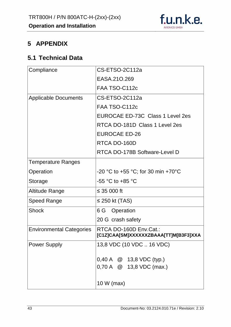
TRT800H PN 800ATC-H-(2xx)-(2xx)
Operation and Installation
44 Document-No 03212401071e Revision 210
Fuse External 2A-slow-blow fuse
Mounting Panel cut-out d=575 mm
Weight 06 kg (132 lbs)
Receiver Characteristics
Sensitivity
RF input power level resulting in a 90 reply rate
A MTL for ATCRBS and ATCRBSMode S All-Call interrogations -74 dBm plusmn3 dB
B MTL for Mode S interrogations -74 dBm plusmn 3 dB
Reply transmission frequency
1090 plusmn 1 MHz
RF Peak Power Output 21 dBW (126 W) at antenna base (with maximum cable attenuation of 15 dB)
Squitter (ADS-B) transmitted at random intervals uniformly distributed over the range from 08 to 12 seconds full self-verification of data and occurrence
Mode S Elementary Surveillance
ICAO 24-bit Aircraft Address (Hex-Code)
aircraft address as assigned by national aviation authority
FID Flight ID Flight Plan call sign or aircraft registration marking
Capability Report Reports the available data and means by which the transponder can report
Pressure Altitude Up to 35 000 ft in 25 ft increments
Flight Status in-flight on-ground
Mode S Enhanced Surveillance
Level 2es Comm-A Comm-B 56112-Bit-Messages
SI-capability
TRT800H PN 800ATC-H-(2xx)-(2xx)
Operation and Installation
45 Document-No 03212401071e Revision 210
52 Environmental Conditions
Characteristic DOndash160D Section Cat Condition
Temperature Altitude 40
C1
Low ground survival temperature
451 ndash 55degC
Low operating temperature 451 ndash 20degC
High ground survival Temperature
452 + 85degC
High Short-time Operating Temperature
452 + 70degC
High Operating Temperature 453 + 55degC
In-Flight Loss of Cooling 454 Z No auxiliary cooling required
Altitude 461 C1 35 000 ft
Temperature Variation 50 C 2degC change rate minimum per minute
Humidity 60 A
Shock 70 A
6 G operational shocks
20 G Crash Safety
Test Type R in all 6 directions
Vibration 80 S Vibration Curve M
Explosion Proofness 90 X No test required
Water Proofness 100 X No test required
Fluids Susceptibilities 110 X No test required
Sand and Dust 120 X No test required
Fungus Resistance 130 X No test required
Salt Spray 140 X No test required
Magnetic Effect 150 Z Less than 03 m
Power Input (DC) 160 B
Voltage Spike Conducted 170 A
Audio Frequency Conducted Susceptibility
180 A
TRT800H PN 800ATC-H-(2xx)-(2xx)
Operation and Installation
46 Document-No 03212401071e Revision 210
Characteristic DOndash160D Section Cat Condition
Induced Signal Susceptibility 190 A
Radio Frequency Susceptibility
200 TT
Emission of RF Energy 210 M
Lightning Induced Transient Susceptibility
220 B3F3
Lightning Direct Effects 230 X No test required
Icing 240 X No test required
Electrostatic Discharge (ESD) 250 A
53 DO-178B Open Problem Reports
There are no open problem reports for the software of this device
TRT800H PN 800ATC-H-(2xx)-(2xx)
Operation and Installation
47 Document-No 03212401071e Revision 210
Notes
f funke funke means ndash fabrication utilities network know-how engineering
funke AVIONICS GmbH Heinz-Strachowitz-Str 4
DE-86807 Buchloe Germany
phone +49-8241 80066 0
fax +49-8241 80066 99 E-mail
servicefunkeavionicsde wwwfunkeavionicsde
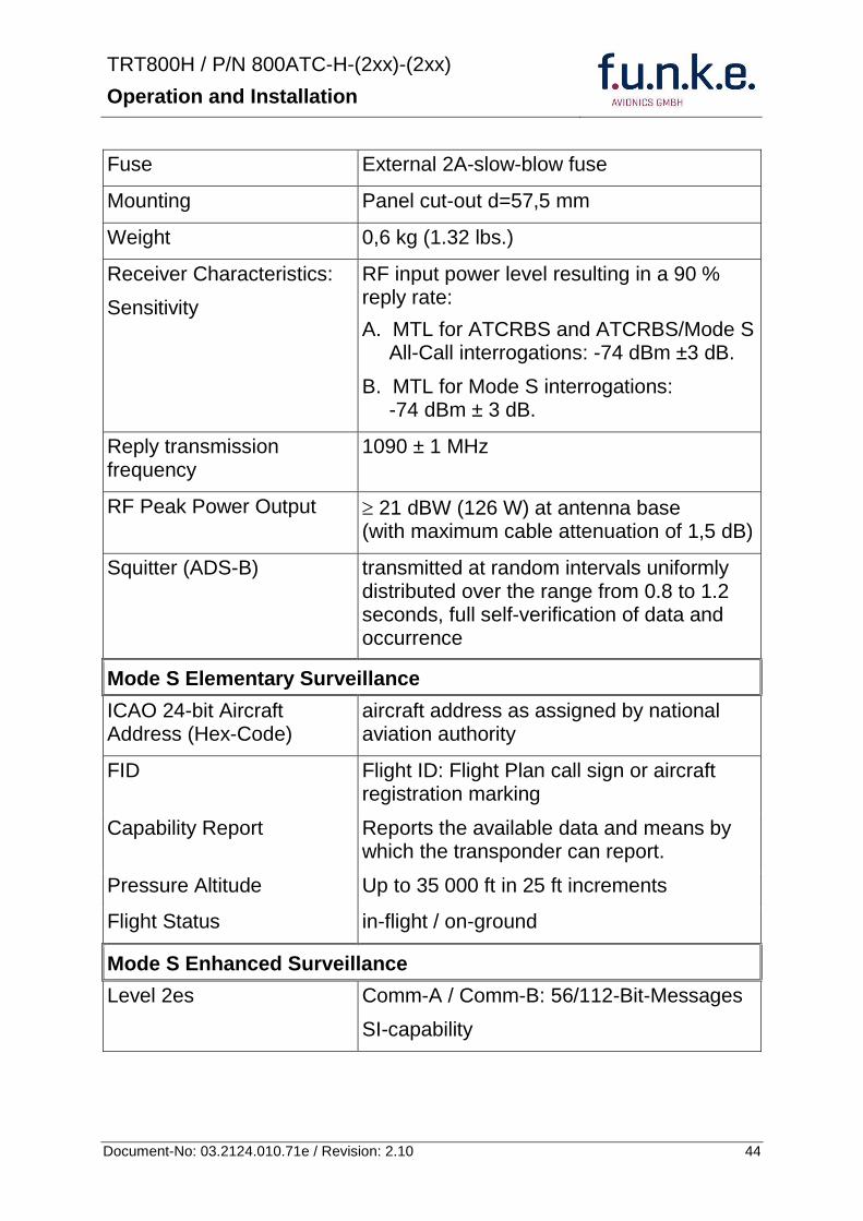
TRT800H PN 800ATC-H-(2xx)-(2xx)
Operation and Installation
45 Document-No 03212401071e Revision 210
52 Environmental Conditions
Characteristic DOndash160D Section Cat Condition
Temperature Altitude 40
C1
Low ground survival temperature
451 ndash 55degC
Low operating temperature 451 ndash 20degC
High ground survival Temperature
452 + 85degC
High Short-time Operating Temperature
452 + 70degC
High Operating Temperature 453 + 55degC
In-Flight Loss of Cooling 454 Z No auxiliary cooling required
Altitude 461 C1 35 000 ft
Temperature Variation 50 C 2degC change rate minimum per minute
Humidity 60 A
Shock 70 A
6 G operational shocks
20 G Crash Safety
Test Type R in all 6 directions
Vibration 80 S Vibration Curve M
Explosion Proofness 90 X No test required
Water Proofness 100 X No test required
Fluids Susceptibilities 110 X No test required
Sand and Dust 120 X No test required
Fungus Resistance 130 X No test required
Salt Spray 140 X No test required
Magnetic Effect 150 Z Less than 03 m
Power Input (DC) 160 B
Voltage Spike Conducted 170 A
Audio Frequency Conducted Susceptibility
180 A
TRT800H PN 800ATC-H-(2xx)-(2xx)
Operation and Installation
46 Document-No 03212401071e Revision 210
Characteristic DOndash160D Section Cat Condition
Induced Signal Susceptibility 190 A
Radio Frequency Susceptibility
200 TT
Emission of RF Energy 210 M
Lightning Induced Transient Susceptibility
220 B3F3
Lightning Direct Effects 230 X No test required
Icing 240 X No test required
Electrostatic Discharge (ESD) 250 A
53 DO-178B Open Problem Reports
There are no open problem reports for the software of this device
TRT800H PN 800ATC-H-(2xx)-(2xx)
Operation and Installation
47 Document-No 03212401071e Revision 210
Notes
f funke funke means ndash fabrication utilities network know-how engineering
funke AVIONICS GmbH Heinz-Strachowitz-Str 4
DE-86807 Buchloe Germany
phone +49-8241 80066 0
fax +49-8241 80066 99 E-mail
servicefunkeavionicsde wwwfunkeavionicsde
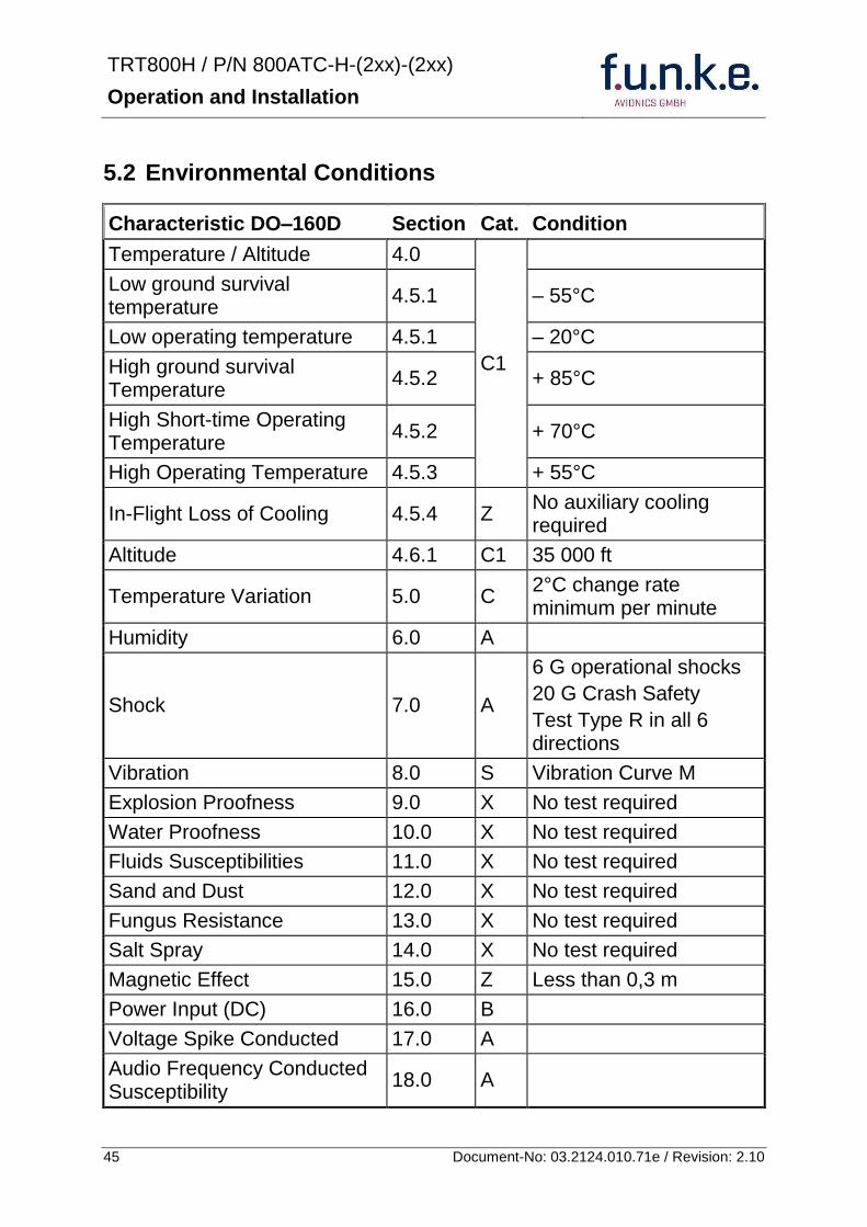
TRT800H PN 800ATC-H-(2xx)-(2xx)
Operation and Installation
46 Document-No 03212401071e Revision 210
Characteristic DOndash160D Section Cat Condition
Induced Signal Susceptibility 190 A
Radio Frequency Susceptibility
200 TT
Emission of RF Energy 210 M
Lightning Induced Transient Susceptibility
220 B3F3
Lightning Direct Effects 230 X No test required
Icing 240 X No test required
Electrostatic Discharge (ESD) 250 A
53 DO-178B Open Problem Reports
There are no open problem reports for the software of this device
TRT800H PN 800ATC-H-(2xx)-(2xx)
Operation and Installation
47 Document-No 03212401071e Revision 210
Notes
f funke funke means ndash fabrication utilities network know-how engineering
funke AVIONICS GmbH Heinz-Strachowitz-Str 4
DE-86807 Buchloe Germany
phone +49-8241 80066 0
fax +49-8241 80066 99 E-mail
servicefunkeavionicsde wwwfunkeavionicsde
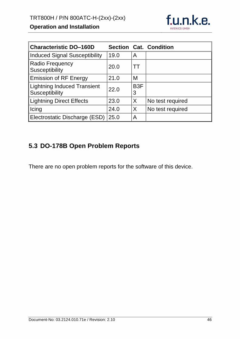
TRT800H PN 800ATC-H-(2xx)-(2xx)
Operation and Installation
47 Document-No 03212401071e Revision 210
Notes
f funke funke means ndash fabrication utilities network know-how engineering
funke AVIONICS GmbH Heinz-Strachowitz-Str 4
DE-86807 Buchloe Germany
phone +49-8241 80066 0
fax +49-8241 80066 99 E-mail
servicefunkeavionicsde wwwfunkeavionicsde

f funke funke means ndash fabrication utilities network know-how engineering
funke AVIONICS GmbH Heinz-Strachowitz-Str 4
DE-86807 Buchloe Germany
phone +49-8241 80066 0
fax +49-8241 80066 99 E-mail
servicefunkeavionicsde wwwfunkeavionicsde