Embed Size (px)
Citation preview
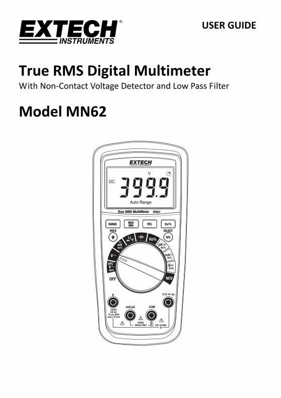
USER GUIDE
True RMS Digital Multimeter With Non‐Contact Voltage Detector and Low Pass Filter
Model MN62
MN62‐en‐GB_V1.1 12/15 2
Introduction Thank you for selecting the Model MN62 True RMS Auto‐ranging Multimeter. This meter measures AC/DC Voltage, AC/DC Current, Variable Frequency Voltage (VFC), Resistance, Capacitance, Frequency, Duty Cycle (AC only), Diode Test, and Continuity; a Non‐Contact Voltage Detector is also built‐in. This device is shipped fully tested and calibrated and, with proper use, will provide years of reliable service. Please visit our website (www.extech.com) to check for the latest version of this User Guide, Product Updates, Product Registration, and Customer Support.
Features
True RMS AC Measurements
Non‐contact Voltage Detector
4000 Count Multifunction LCD Display
Automatic and Manual Ranging
MAX‐MIN Reading Memory
Relative Mode
Data Hold
Variable Frequency Voltage mode (VFC) offers low pass filter
Automatic Power OFF (APO)
Rugged, Battery Operated, and Portable
MN62‐en‐GB_V1.1 12/15 3
Safety
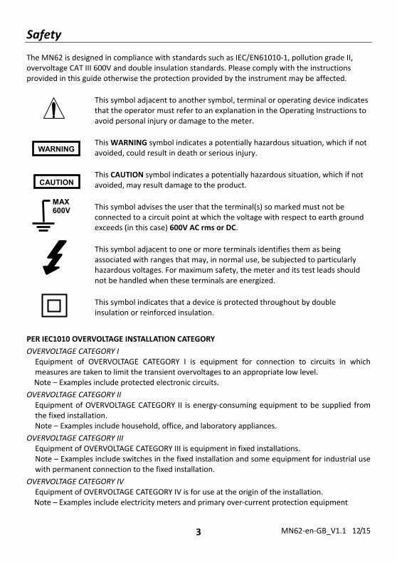
The MN62 is designed in compliance with standards such as IEC/EN61010‐1, pollution grade II, overvoltage CAT III 600V and double insulation standards. Please comply with the instructions provided in this guide otherwise the protection provided by the instrument may be affected.
This symbol adjacent to another symbol, terminal or operating device indicates that the operator must refer to an explanation in the Operating Instructions to avoid personal injury or damage to the meter.
This WARNING symbol indicates a potentially hazardous situation, which if not avoided, could result in death or serious injury.
This CAUTION symbol indicates a potentially hazardous situation, which if not avoided, may result damage to the product.
This symbol advises the user that the terminal(s) so marked must not be connected to a circuit point at which the voltage with respect to earth ground exceeds (in this case) 600V AC rms or DC.
This symbol adjacent to one or more terminals identifies them as being associated with ranges that may, in normal use, be subjected to particularly hazardous voltages. For maximum safety, the meter and its test leads should not be handled when these terminals are energized.
This symbol indicates that a device is protected throughout by double insulation or reinforced insulation.
PER IEC1010 OVERVOLTAGE INSTALLATION CATEGORY
OVERVOLTAGE CATEGORY I Equipment of OVERVOLTAGE CATEGORY I is equipment for connection to circuits in which measures are taken to limit the transient overvoltages to an appropriate low level.
Note – Examples include protected electronic circuits.
OVERVOLTAGE CATEGORY II Equipment of OVERVOLTAGE CATEGORY II is energy‐consuming equipment to be supplied from the fixed installation.
Note – Examples include household, office, and laboratory appliances.
OVERVOLTAGE CATEGORY III Equipment of OVERVOLTAGE CATEGORY III is equipment in fixed installations.
Note – Examples include switches in the fixed installation and some equipment for industrial use with permanent connection to the fixed installation.
OVERVOLTAGE CATEGORY IV Equipment of OVERVOLTAGE CATEGORY IV is for use at the origin of the installation. Note – Examples include electricity meters and primary over‐current protection equipment
WARNING
CAUTION
MAX 600V
MN62‐en‐GB_V1.1 12/15 4
CAUTIONS Improper use of this meter can cause damage, shock, injury or death. Read and understand this user
manual before operating the meter.
Always remove the test leads before replacing the battery or fuses.
Inspect the condition of the test leads and the meter itself for any damage before operating the meter.
Use great care when making measurements if the voltages are greater than 30VAC rms or 60VDC. These voltages are considered a shock hazard.
Always discharge capacitors and remove power from the device under test before performing Diode, Resistance or Continuity tests.
Voltage checks on electrical outlets can be difficult and misleading because of the uncertainty of connection to the recessed electrical contacts. Other means should be used to ensure that the terminals are not "live".
If the equipment is used in a manner not specified by the manufacturer, the protection provided by the equipment may be impaired.
This device is not a toy and must not reach children’s hands. It contains hazardous objects as well as small parts that the children could swallow.
In case the device is going to be unused for an extended period of time, remove the batteries and store them separately.
Expired or damaged batteries can cause cauterization on contact with the skin. Use protective gloves when handling.
Do not short‐circuit the batteries. Do not throw batteries into a fire.
This meter has been designed for safe use, but must be operated with caution. The rules listed below must be carefully followed for safe operation.
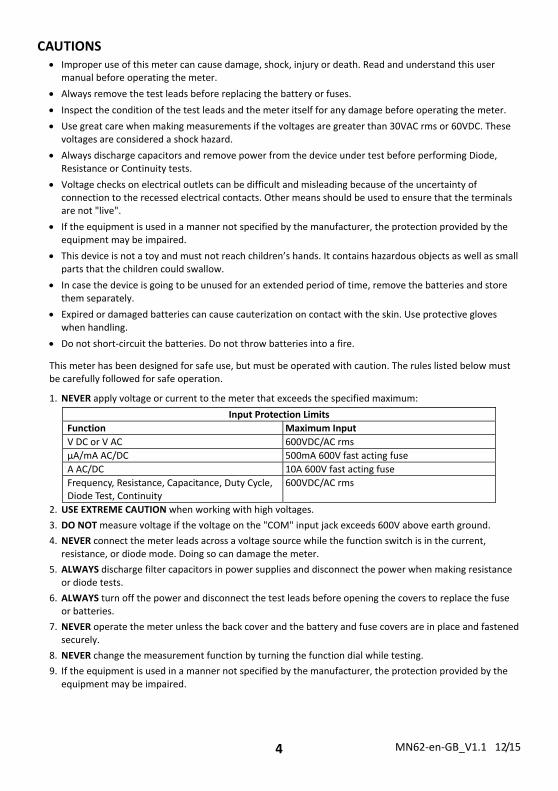
1. NEVER apply voltage or current to the meter that exceeds the specified maximum:
Input Protection Limits
Function Maximum Input
V DC or V AC 600VDC/AC rms
µA/mA AC/DC 500mA 600V fast acting fuse
A AC/DC 10A 600V fast acting fuse
Frequency, Resistance, Capacitance, Duty Cycle, Diode Test, Continuity
600VDC/AC rms
2. USE EXTREME CAUTION when working with high voltages.
3. DO NOT measure voltage if the voltage on the "COM" input jack exceeds 600V above earth ground.
4. NEVER connect the meter leads across a voltage source while the function switch is in the current, resistance, or diode mode. Doing so can damage the meter.
5. ALWAYS discharge filter capacitors in power supplies and disconnect the power when making resistance or diode tests.
6. ALWAYS turn off the power and disconnect the test leads before opening the covers to replace the fuse or batteries.
7. NEVER operate the meter unless the back cover and the battery and fuse covers are in place and fastened securely.
8. NEVER change the measurement function by turning the function dial while testing.
9. If the equipment is used in a manner not specified by the manufacturer, the protection provided by the equipment may be impaired.
MN62‐en‐GB_V1.1 12/15 5
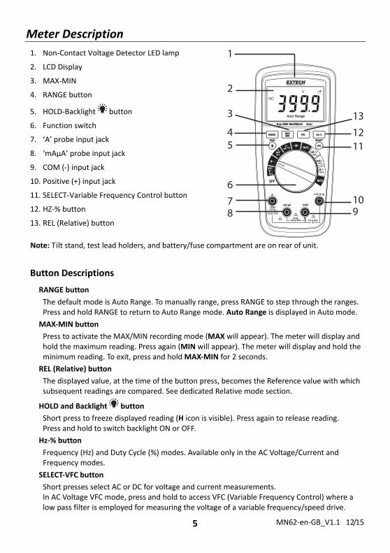
Meter Description
1. Non‐Contact Voltage Detector LED lamp
2. LCD Display
3. MAX‐MIN
4. RANGE button
5. HOLD‐Backlight button
6. Function switch
7. ‘A’ probe input jack
8. ‘mAµA’ probe input jack
9. COM (‐) input jack
10. Positive (+) input jack
11. SELECT‐Variable Frequency Control button
12. HZ‐% button
13. REL (Relative) button
Note: Tilt stand, test lead holders, and battery/fuse compartment are on rear of unit.
Button Descriptions
RANGE button
The default mode is Auto Range. To manually range, press RANGE to step through the ranges. Press and hold RANGE to return to Auto Range mode. Auto Range is displayed in Auto mode.
MAX‐MIN button
Press to activate the MAX/MIN recording mode (MAX will appear). The meter will display and hold the maximum reading. Press again (MIN will appear). The meter will display and hold the minimum reading. To exit, press and hold MAX‐MIN for 2 seconds.
REL (Relative) button
The displayed value, at the time of the button press, becomes the Reference value with which subsequent readings are compared. See dedicated Relative mode section.
HOLD and Backlight button
Short press to freeze displayed reading (H icon is visible). Press again to release reading. Press and hold to switch backlight ON or OFF.
Hz‐% button
Frequency (Hz) and Duty Cycle (%) modes. Available only in the AC Voltage/Current and Frequency modes.
SELECT‐VFC button
Short presses select AC or DC for voltage and current measurements. In AC Voltage VFC mode, press and hold to access VFC (Variable Frequency Control) where a low pass filter is employed for measuring the voltage of a variable frequency/speed drive.
1
2
3
45
6
78 9
10
1112
13
MN62‐en‐GB_V1.1 12/15 6
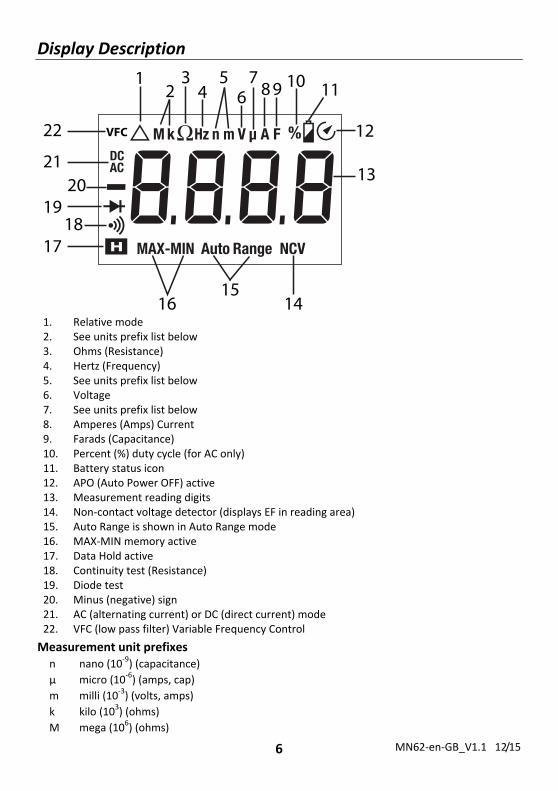
Display Description
12
34
56
78 9 10 11
12
1415
16
1718
1920
2113
VFC22
1. Relative mode 2. See units prefix list below 3. Ohms (Resistance) 4. Hertz (Frequency) 5. See units prefix list below 6. Voltage 7. See units prefix list below 8. Amperes (Amps) Current 9. Farads (Capacitance) 10. Percent (%) duty cycle (for AC only) 11. Battery status icon 12. APO (Auto Power OFF) active 13. Measurement reading digits 14. Non‐contact voltage detector (displays EF in reading area) 15. Auto Range is shown in Auto Range mode 16. MAX‐MIN memory active 17. Data Hold active 18. Continuity test (Resistance) 19. Diode test 20. Minus (negative) sign 21. AC (alternating current) or DC (direct current) mode 22. VFC (low pass filter) Variable Frequency Control
Measurement unit prefixes n nano (10‐9) (capacitance)
µ micro (10‐6) (amps, cap)
m milli (10‐3) (volts, amps)
k kilo (103) (ohms)
M mega (106) (ohms)
MN62‐en‐GB_V1.1 12/15 7
Operating Instructions
WARNING: Risk of electrocution. High‐voltage circuits, both AC and DC, are very dangerous and should be measured with great care.
1. ALWAYS turn the function switch to the OFF position when the meter is not in use.
2. If OL appears in the display during a measurement, the value exceeds the selected range. Change to a higher range.
3. If the meter does not switch on when the function dial is turned to any position other than OFF, please check the batteries. Refer to the Battery Installation section of this guide.
AUTO POWER OFF (APO) The APO feature turns the meter off after 15 minutes of inactivity. To disable APO, hold the SELECT button while turning the meter on. The meter will emit 5 beeps indicating that APO has been disabled (the APO clock icon will not be visible on the display). Turn the meter off and then on again to re‐enable APO (the APO clock icon will be visible on the display when APO is active).
AUTOMATIC and MANUAL Range The meter defaults to AUTO Range mode when it is switched ON. In this mode the meter automatically selects the best range for the measurements being made and is generally the best mode for most measurements. For measurement situations requiring that a range be manually selected, perform the following:
1. Press the RANGE button. The “AUTO RANGE” display indicator will turn off.
2. Press the RANGE button to step through the available ranges.
3. To exit the Manual Ranging mode and return to Auto ranging, press and hold the RANGE button for 2 seconds.
MAX/MIN Memory 1. Press the MAX/MIN button to activate the MAX/MIN recording mode. The display icon MAX
will appear. The meter will display and hold the maximum reading and will update only when a new maximum reading occurs.
2. Press the MAX/MIN button again and the display icon MIN will appear. The meter will display and hold the minimum reading and will update only when a new minimum reading occurs.
3. To exit MAX/MIN mode press and hold the MAX/MIN button for 2 seconds.
Relative mode The relative measurement feature allows the user to make measurements relative to a stored reference value. A reference voltage, current, etc. can be stored where subsequent measurements can be made in comparison to that stored reference value. The displayed value is the difference between the reference value and the measured value.
1. Perform a measurement as described in the operating instructions.
2. Press the REL button to store the reading; the Relative indicator will appear on the display.
3. The display will now indicate the difference between the stored and measured value.
4. Press the REL button to exit the relative mode. The Relative indicator will switch OFF.

MN62‐en‐GB_V1.1 12/15 8
Display Backlight
Press and hold the button to turn the backlight ON/OFF. The backlight will automatically turn off after 30 seconds.
Data Hold The Data Hold function freezes the reading in the display. Press the HOLD button to switch Data Hold ON/OFF. When the Data Hold mode is active the display will show the H icon.
DC VOLTAGE MEASUREMENTS
CAUTION: Do not measure DC voltages if a motor on the circuit is being switched ON or OFF. Large voltage surges may occur that can damage the meter.
1. Set the function switch to the V position.
2. Press the SELECT button to switch to DC if necessary.
3. Insert the black test lead banana plug into the negative COM jack. Insert the red test lead banana plug into the positive V jack.
4. Touch the black test probe tip to the negative side of the circuit. Touch the red test probe tip to the positive side of the circuit.
5. Use the RANGE button to manually range the reading. Press and hold the RANGE button to return to Auto Range Mode. Read the voltage in the display.
AC VOLTAGE MEASUREMENTS
WARNING: Risk of Electrocution. The probe tips may not be long enough to contact the live parts inside some 240V outlets for appliances because the contacts are recessed deep in the outlets. As a result, the reading may show 0 volts when the outlet actually has voltage on it. Make sure the probe tips are touching the metal contacts inside the outlet before assuming that no voltage is present.
CAUTION: Do not measure AC voltages if a motor on the circuit is being switched ON or OFF. Large voltage surges may occur that can damage the meter.
1. Set the function switch to the V position.
2. Press the SELECT button to switch to AC if necessary.
3. Insert the black test lead banana plug into the negative COM jack. Insert red test lead banana plug into the positive V jack.
4. Touch the black test probe tip to the neutral side of the circuit. Touch the red test probe tip to the “hot” side of the circuit.
5. Read the voltage in the display.
6. Use the RANGE button to manually range the reading. Press and hold the RANGE button to return to Auto Range Mode.
MN62‐en‐GB_V1.1 12/15 9
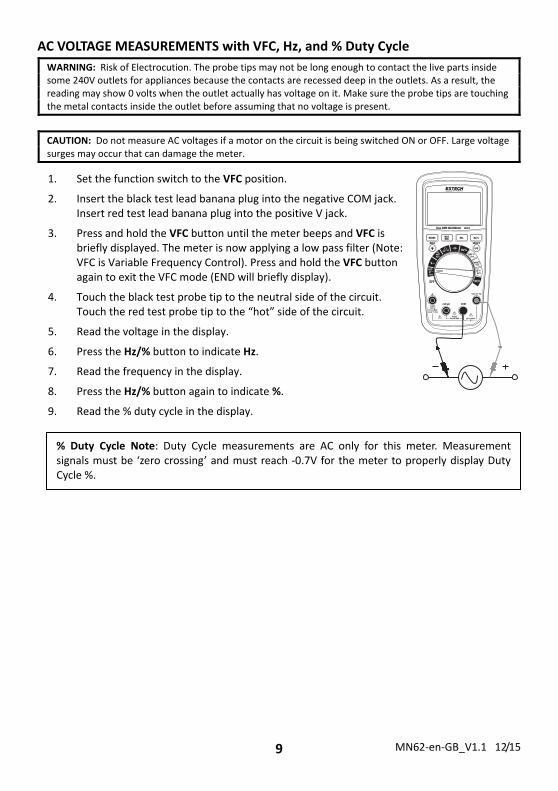
AC VOLTAGE MEASUREMENTS with VFC, Hz, and % Duty Cycle
WARNING: Risk of Electrocution. The probe tips may not be long enough to contact the live parts inside some 240V outlets for appliances because the contacts are recessed deep in the outlets. As a result, the reading may show 0 volts when the outlet actually has voltage on it. Make sure the probe tips are touching the metal contacts inside the outlet before assuming that no voltage is present.
CAUTION: Do not measure AC voltages if a motor on the circuit is being switched ON or OFF. Large voltage surges may occur that can damage the meter.
1. Set the function switch to the VFC position.
2. Insert the black test lead banana plug into the negative COM jack. Insert red test lead banana plug into the positive V jack.
3. Press and hold the VFC button until the meter beeps and VFC is briefly displayed. The meter is now applying a low pass filter (Note: VFC is Variable Frequency Control). Press and hold the VFC button again to exit the VFC mode (END will briefly display).
4. Touch the black test probe tip to the neutral side of the circuit. Touch the red test probe tip to the “hot” side of the circuit.
5. Read the voltage in the display.
6. Press the Hz/% button to indicate Hz.
7. Read the frequency in the display.
8. Press the Hz/% button again to indicate %.
9. Read the % duty cycle in the display.
% Duty Cycle Note: Duty Cycle measurements are AC only for this meter. Measurement signals must be ‘zero crossing’ and must reach ‐0.7V for the meter to properly display Duty Cycle %.
MN62‐en‐GB_V1.1 12/15 10
DC/AC MILLIVOLT MEASUREMENTS
CAUTION: Do not measure DC/AC voltages if a motor on the circuit is being switched ON or OFF. Large voltage surges may occur that can damage the meter.
1. Set the function switch to the mV position.
2. Insert the black test lead banana plug into the negative COM jack. Insert the red test lead banana plug into the positive V jack.
3. Press the SELECT button to select DC or AC millivolts.
4. Touch the black test probe tip to the negative side of the circuit. Touch the red test probe tip to the positive side of the circuit. (Figure at right shows DC measurement only).
5. Read the voltage in the display.
6. For AC, press the Hz/% button to indicate Hz.
7. Read the frequency in the display.
8. For AC, press the Hz/% button again to indicate %.
9. Read the % duty cycle in the display.
DC CURRENT MEASUREMENTS
CAUTION: Do not make 5A current measurements for longer than 30 seconds. Allow 15 minutes between tests. Exceeding 30 seconds may cause damage to the meter and/or the test leads.
1. Insert black test lead banana plug into the negative COM jack.
2. For current measurements up to 6000µA DC, set the function switch to the µA position and insert the red test lead banana plug into the µA/mA jack.
3. For current measurements up to 600mA DC, set the function switch to the mA position and insert the red test lead banana plug into the µA/mA jack.
4. For current measurements up to 10A DC, set the function switch to the A position and insert the red test lead banana plug into the 10A jack.
5. Press the SELECT button to indicate DC on the display.
6. Remove power from the circuit under test, then open up the circuit at the point where you wish to measure current.
7. Touch the black test probe tip to the negative side of the circuit. Touch the red test probe tip to the positive side of the circuit.
8. Apply power to the circuit.
9. Read the current in the display.
MN62‐en‐GB_V1.1 12/15 11
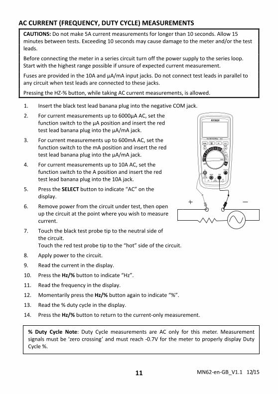
AC CURRENT (FREQUENCY, DUTY CYCLE) MEASUREMENTS
CAUTIONS: Do not make 5A current measurements for longer than 10 seconds. Allow 15 minutes between tests. Exceeding 10 seconds may cause damage to the meter and/or the test leads.
Before connecting the meter in a series circuit turn off the power supply to the series loop. Start with the highest range possible if unsure of expected current measurement.
Fuses are provided in the 10A and µA/mA input jacks. Do not connect test leads in parallel to any circuit when test leads are connected to these jacks.
Pressing the HZ‐% button, while taking AC current measurements, is allowed.
1. Insert the black test lead banana plug into the negative COM jack.
2. For current measurements up to 6000µA AC, set the function switch to the µA position and insert the red test lead banana plug into the µA/mA jack.
3. For current measurements up to 600mA AC, set the function switch to the mA position and insert the red test lead banana plug into the µA/mA jack.
4. For current measurements up to 10A AC, set the function switch to the A position and insert the red test lead banana plug into the 10A jack.
5. Press the SELECT button to indicate “AC” on the display.
6. Remove power from the circuit under test, then open up the circuit at the point where you wish to measure current.
7. Touch the black test probe tip to the neutral side of the circuit. Touch the red test probe tip to the “hot” side of the circuit.
8. Apply power to the circuit.
9. Read the current in the display.
10. Press the Hz/% button to indicate “Hz”.
11. Read the frequency in the display.
12. Momentarily press the Hz/% button again to indicate “%”.
13. Read the % duty cycle in the display.
14. Press the Hz/% button to return to the current‐only measurement.
% Duty Cycle Note: Duty Cycle measurements are AC only for this meter. Measurement signals must be ‘zero crossing’ and must reach ‐0.7V for the meter to properly display Duty Cycle %.
MN62‐en‐GB_V1.1 12/15 12
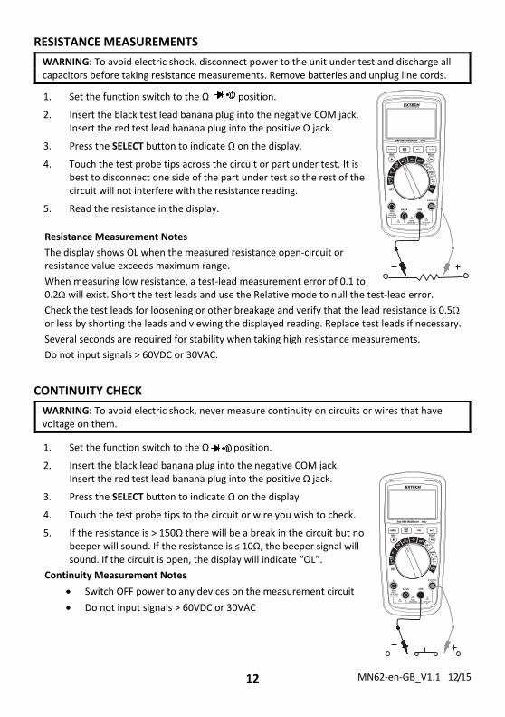
RESISTANCE MEASUREMENTS
WARNING: To avoid electric shock, disconnect power to the unit under test and discharge all capacitors before taking resistance measurements. Remove batteries and unplug line cords.
1. Set the function switch to the Ω position.
2. Insert the black test lead banana plug into the negative COM jack. Insert the red test lead banana plug into the positive Ω jack.
3. Press the SELECT button to indicate Ω on the display.
4. Touch the test probe tips across the circuit or part under test. It is best to disconnect one side of the part under test so the rest of the circuit will not interfere with the resistance reading.
5. Read the resistance in the display.
Resistance Measurement Notes
The display shows OL when the measured resistance open‐circuit or resistance value exceeds maximum range.
When measuring low resistance, a test‐lead measurement error of 0.1 to 0.2 will exist. Short the test leads and use the Relative mode to null the test‐lead error.
Check the test leads for loosening or other breakage and verify that the lead resistance is 0.5 or less by shorting the leads and viewing the displayed reading. Replace test leads if necessary.
Several seconds are required for stability when taking high resistance measurements.
Do not input signals > 60VDC or 30VAC.
CONTINUITY CHECK
WARNING: To avoid electric shock, never measure continuity on circuits or wires that have voltage on them.
1. Set the function switch to the Ω position.
2. Insert the black lead banana plug into the negative COM jack. Insert the red test lead banana plug into the positive Ω jack.
3. Press the SELECT button to indicate Ω on the display
4. Touch the test probe tips to the circuit or wire you wish to check.
5. If the resistance is > 150Ω there will be a break in the circuit but no beeper will sound. If the resistance is ≤ 10Ω, the beeper signal will sound. If the circuit is open, the display will indicate “OL”.
Continuity Measurement Notes
Switch OFF power to any devices on the measurement circuit
Do not input signals > 60VDC or 30VAC
MN62‐en‐GB_V1.1 12/15 13
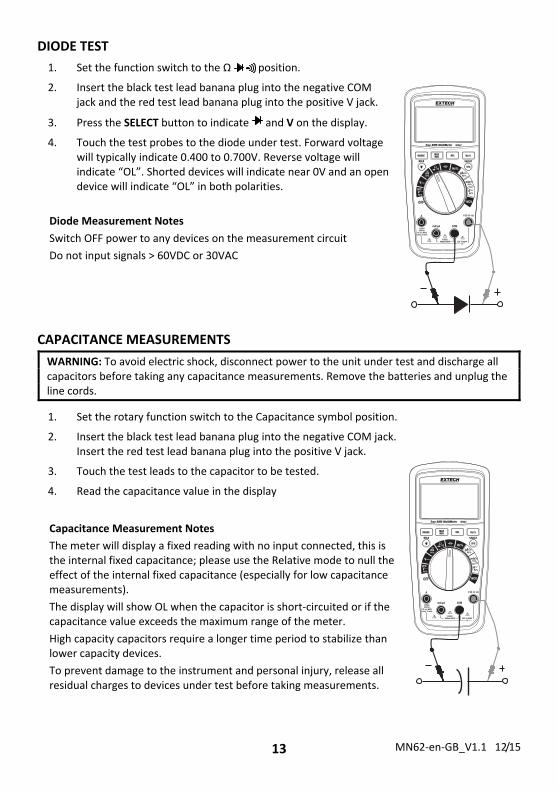
DIODE TEST
1. Set the function switch to the Ω position.
2. Insert the black test lead banana plug into the negative COM jack and the red test lead banana plug into the positive V jack.
3. Press the SELECT button to indicate and V on the display.
4. Touch the test probes to the diode under test. Forward voltage will typically indicate 0.400 to 0.700V. Reverse voltage will indicate “OL”. Shorted devices will indicate near 0V and an open device will indicate “OL” in both polarities.
Diode Measurement Notes
Switch OFF power to any devices on the measurement circuit
Do not input signals > 60VDC or 30VAC
CAPACITANCE MEASUREMENTS
WARNING: To avoid electric shock, disconnect power to the unit under test and discharge all capacitors before taking any capacitance measurements. Remove the batteries and unplug the line cords.
1. Set the rotary function switch to the Capacitance symbol position.
2. Insert the black test lead banana plug into the negative COM jack. Insert the red test lead banana plug into the positive V jack.
3. Touch the test leads to the capacitor to be tested.
4. Read the capacitance value in the display
Capacitance Measurement Notes
The meter will display a fixed reading with no input connected, this is the internal fixed capacitance; please use the Relative mode to null the effect of the internal fixed capacitance (especially for low capacitance measurements).
The display will show OL when the capacitor is short‐circuited or if the capacitance value exceeds the maximum range of the meter.
High capacity capacitors require a longer time period to stabilize than lower capacity devices.
To prevent damage to the instrument and personal injury, release all residual charges to devices under test before taking measurements.
MN62‐en‐GB_V1.1 12/15 14
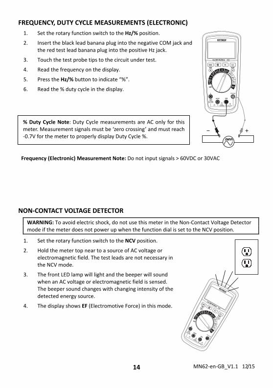
FREQUENCY, DUTY CYCLE MEASUREMENTS (ELECTRONIC)
1. Set the rotary function switch to the Hz/% position.
2. Insert the black lead banana plug into the negative COM jack and the red test lead banana plug into the positive Hz jack.
3. Touch the test probe tips to the circuit under test.
4. Read the frequency on the display.
5. Press the Hz/% button to indicate “%”.
6. Read the % duty cycle in the display.
Frequency (Electronic) Measurement Note: Do not input signals > 60VDC or 30VAC
NON‐CONTACT VOLTAGE DETECTOR
WARNING: To avoid electric shock, do not use this meter in the Non‐Contact Voltage Detector mode if the meter does not power up when the function dial is set to the NCV position.
1. Set the rotary function switch to the NCV position.
2. Hold the meter top near to a source of AC voltage or electromagnetic field. The test leads are not necessary in the NCV mode.
3. The front LED lamp will light and the beeper will sound when an AC voltage or electromagnetic field is sensed. The beeper sound changes with changing intensity of the detected energy source.
4. The display shows EF (Electromotive Force) in this mode.
% Duty Cycle Note: Duty Cycle measurements are AC only for this meter. Measurement signals must be ‘zero crossing’ and must reach ‐0.7V for the meter to properly display Duty Cycle %.
MN62‐en‐GB_V1.1 12/15 15
Maintenance
WARNING: To avoid electric shock, disconnect the test leads from any source of voltage before removing the back cover or the battery or fuse covers.
WARNING: To avoid electric shock, do not operate your meter until the battery and fuse covers are in place and fastened securely.
This meter is designed to provide years of dependable service, if the following care instructions are performed:
1. KEEP THE METER DRY. If it gets wet, wipe it off.
2. USE AND STORE THE METER IN NORMAL TEMPERATURES. Temperature extremes can shorten the life of the electronic parts and distort or melt plastic parts.
3. HANDLE THE METER GENTLY AND CAREFULLY. Dropping it can damage the electronic parts or the case.
4. KEEP THE METER CLEAN. Wipe the case occasionally with a damp cloth. DO NOT use chemicals, cleaning solvents, or detergents.
5. USE ONLY FRESH BATTERIES OF THE RECOMMENDED SIZE AND TYPE. Remove old or weak batteries so they do not leak and damage the unit.
6. IF THE METER IS TO BE STORED FOR A LONG PERIOD OF TIME, the batteries should be removed to prevent damage to the unit.
BATTERY INSTALLATION
WARNING: To avoid electric shock, disconnect the test leads from any source of voltage before removing the battery cover.
1. Turn power off and disconnect the test leads from the meter.
2. Open the rear battery cover (behind the tilt stand) by removing the screw using a Phillips head screwdriver.
3. Replace the two (2) 1.5V AA batteries in the battery holder, observing correct polarity.
4. Put the battery cover back in place. Secure with the screw.
Never dispose of used batteries or rechargeable batteries in household waste. As consumers, users are legally required to take used batteries to appropriate collection sites, the retail store where the batteries were purchased, or wherever batteries are sold.
Disposal: Do not dispose of this instrument in household waste. The user is obligated to take end‐of‐life devices to a designated collection point for the disposal of electrical and electronic equipment.
WARNING: To avoid electric shock, do not operate the meter until the battery cover is in place and fastened securely.
NOTE: If the meter does not work properly, check the fuses and batteries to make sure that they are still good and that they are properly inserted.
MN62‐en‐GB_V1.1 12/15 16
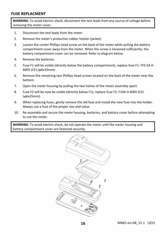
FUSE REPLACMENT
WARNING: To avoid electric shock, disconnect the test leads from any source of voltage before removing the meter cover.
1. Disconnect the test leads from the meter.
2. Remove the meter’s protective rubber holster (jacket).
3. Loosen the center Phillips head screw on the back of the meter while pulling the battery compartment cover away from the meter. When the screw is loosened sufficiently, the battery compartment cover can be removed. Refer to diagram below.
4. Remove the batteries.
5. Fuse F1 will be visible (directly below the battery compartment); replace fuse F1: FF0.5A H 600V (CE) (ϕ6x32mm).
6. Remove the remaining two Phillips head screws located on the back of the meter near the bottom.
7. Open the meter housing by pulling the two halves of the meter assembly apart.
8. Fuse F2 will be now be visible (directly below F1); replace fuse F2: F10A H 600V (CE) (ϕ6x25mm).
9. When replacing fuses, gently remove the old fuse and install the new fuse into the holder. Always use a fuse of the proper size and value.
10. Re‐assemble and secure the meter housing, batteries, and battery cover before attempting to use the meter.
WARNING: To avoid electric shock, do not operate the meter until the meter housing and battery compartment cover are fastened securely.
MN62‐en‐GB_V1.1 12/15 17
Specifications
Specifications stated for ambient conditions 23oC ±5oC (73.4oF ±9oF); Relative Humidity < 75%
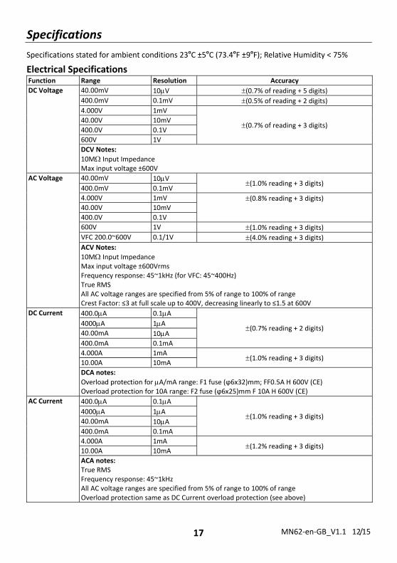
Electrical Specifications Function Range Resolution Accuracy
DC Voltage
40.00mV 10V (0.7% of reading + 5 digits) 400.0mV 0.1mV (0.5% of reading + 2 digits) 4.000V 1mV
(0.7% of reading + 3 digits) 40.00V 10mV
400.0V 0.1V
600V 1V
DCV Notes:
10M Input Impedance Max input voltage ±600V
AC Voltage
40.00mV 10V (1.0% reading + 3 digits)
400.0mV 0.1mV
4.000V 1mV (0.8% reading + 3 digits) 40.00V 10mV
400.0V 0.1V
600V 1V (1.0% reading + 3 digits) VFC 200.0~600V 0.1/1V (4.0% reading + 3 digits) ACV Notes:
10M Input Impedance Max input voltage ±600Vrms Frequency response: 45~1kHz (for VFC: 45~400Hz) True RMS All AC voltage ranges are specified from 5% of range to 100% of range Crest Factor: ≤3 at full scale up to 400V, decreasing linearly to ≤1.5 at 600V
DC Current 400.0A 0.1A
(0.7% reading + 2 digits) 4000A 1A 40.00mA 10A 400.0mA 0.1mA
4.000A 1mA(1.0% reading + 3 digits)
10.00A 10mA
DCA notes:
Overload protection for A/mA range: F1 fuse (ϕ6x32)mm; FF0.5A H 600V (CE) Overload protection for 10A range: F2 fuse (ϕ6x25)mm F 10A H 600V (CE)
AC Current
400.0A 0.1A
(1.0% reading + 3 digits) 4000A 1A 40.00mA 10A 400.0mA 0.1mA
4.000A 1mA(1.2% reading + 3 digits)
10.00A 10mA
ACA notes: True RMS Frequency response: 45~1kHz All AC voltage ranges are specified from 5% of range to 100% of range Overload protection same as DC Current overload protection (see above)
MN62‐en‐GB_V1.1 12/15 18
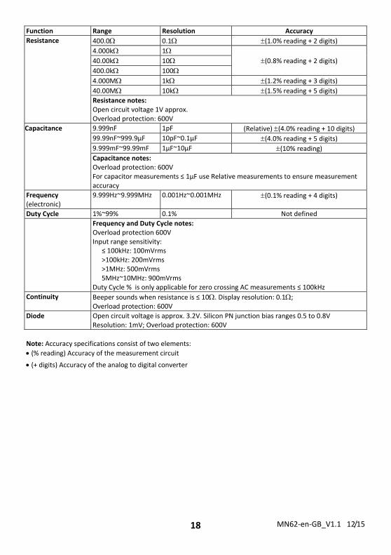
Function Range Resolution Accuracy
Resistance 400.0 0.1 (1.0% reading + 2 digits) 4.000k 1
(0.8% reading + 2 digits) 40.00k 10
400.0k 100
4.000M 1k (1.2% reading + 3 digits) 40.00M 10k (1.5% reading + 5 digits) Resistance notes:Open circuit voltage 1V approx. Overload protection: 600V
Capacitance 9.999nF 1pF (Relative) (4.0% reading + 10 digits) 99.99nF~999.9µF 10pF~0.1µF (4.0% reading + 5 digits) 9.999mF~99.99mF 1µF~10µF (10% reading) Capacitance notes:Overload protection: 600V For capacitor measurements ≤ 1µF use Relative measurements to ensure measurement accuracy
Frequency (electronic)
9.999Hz~9.999MHz 0.001Hz~0.001MHz (0.1% reading + 4 digits)
Duty Cycle 1%~99% 0.1% Not defined
Frequency and Duty Cycle notes:Overload protection 600V Input range sensitivity:
≤ 100kHz: 100mVrms >100kHz: 200mVrms >1MHz: 500mVrms 5MHz~10MHz: 900mVrms
Duty Cycle % is only applicable for zero crossing AC measurements ≤ 100kHz
Continuity Beeper sounds when resistance is ≤ 10. Display resolution: 0.1; Overload protection: 600V
Diode Open circuit voltage is approx. 3.2V. Silicon PN junction bias ranges 0.5 to 0.8VResolution: 1mV; Overload protection: 600V
Note: Accuracy specifications consist of two elements:
(% reading) Accuracy of the measurement circuit
(+ digits) Accuracy of the analog to digital converter
MN62‐en‐GB_V1.1 12/15 19
General Specifications
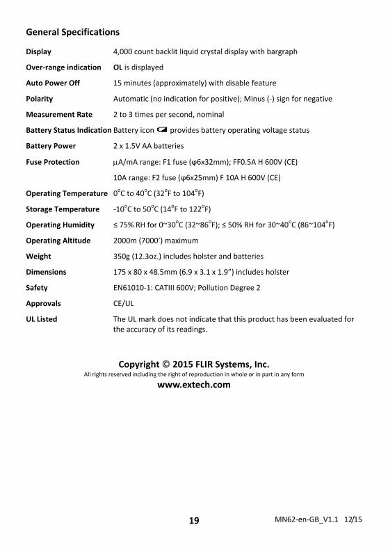
Display 4,000 count backlit liquid crystal display with bargraph
Over‐range indication OL is displayed
Auto Power Off 15 minutes (approximately) with disable feature
Polarity Automatic (no indication for positive); Minus (‐) sign for negative
Measurement Rate 2 to 3 times per second, nominal
Battery Status Indication Battery icon provides battery operating voltage status
Battery Power 2 x 1.5V AA batteries
Fuse Protection A/mA range: F1 fuse (ϕ6x32mm); FF0.5A H 600V (CE)
10A range: F2 fuse (ϕ6x25mm) F 10A H 600V (CE)
Operating Temperature 0oC to 40oC (32oF to 104oF)
Storage Temperature ‐10oC to 50oC (14oF to 122oF)
Operating Humidity ≤ 75% RH for 0~30oC (32~86oF); ≤ 50% RH for 30~40oC (86~104oF)
Operating Altitude 2000m (7000’) maximum
Weight 350g (12.3oz.) includes holster and batteries
Dimensions 175 x 80 x 48.5mm (6.9 x 3.1 x 1.9”) includes holster
Safety EN61010‐1: CATIII 600V; Pollution Degree 2
Approvals CE/UL
UL Listed The UL mark does not indicate that this product has been evaluated for the accuracy of its readings.
Copyright © 2015 FLIR Systems, Inc.
All rights reserved including the right of reproduction in whole or in part in any form
www.extech.com


![Investigating%20 earthquakes%20with%20arcexplorer%20gis[1]](https://img.pdfslide.net/doc/110x75/55bac8ddbb61ebfc108b47c1/investigating20-earthquakes20with20arcexplorer20gis1.jpg)