Embed Size (px)
Citation preview
8/25/2007 11:20 AM 18/25/2007 1
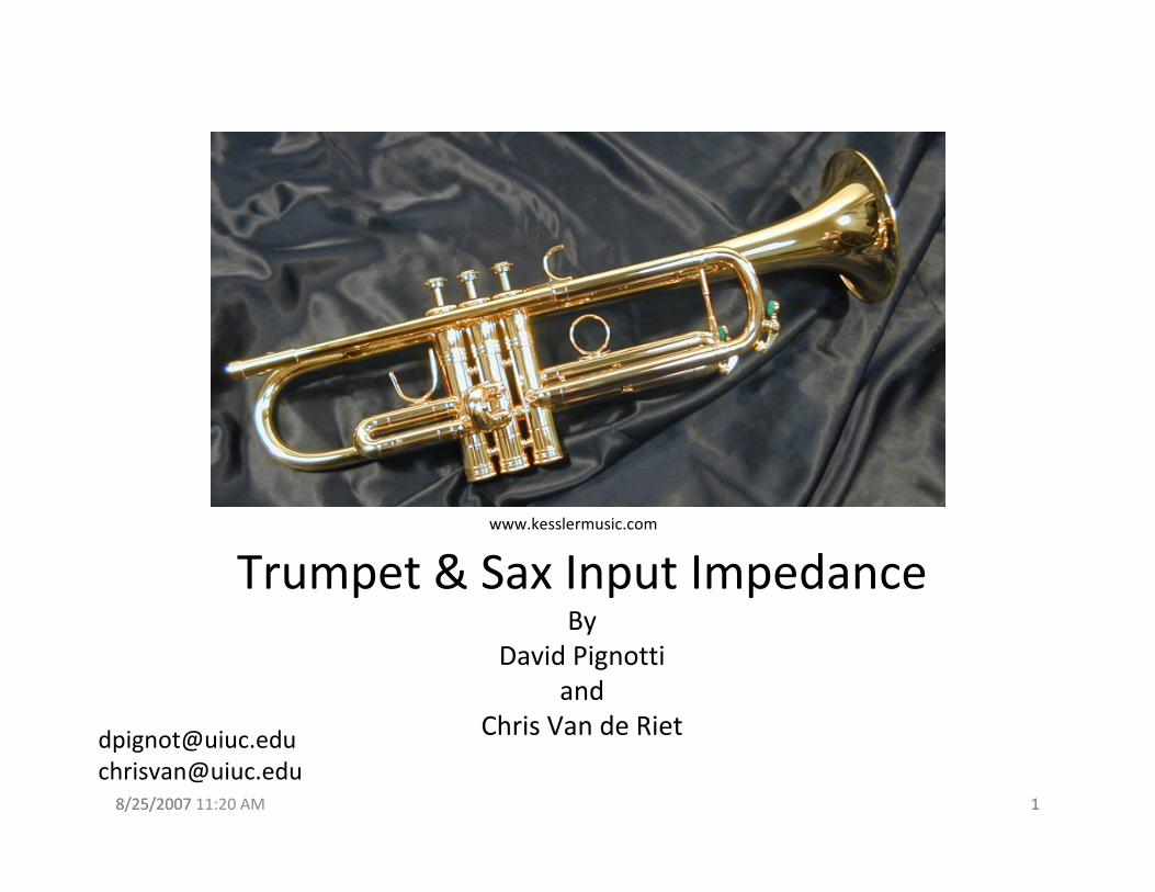
Trumpet & Sax Input ImpedanceBy
David Pignottiand
Chris Van de [email protected]@uiuc.edu
www.kesslermusic.com
8/25/2007 11:20 AM 28/25/2007 2
Outline of Presentation:
• Brief Music Theory
• Construction of Trumpet
• Experimental Apparatus
• Future Work
8/25/2007 11:20 AM 38/25/2007 3
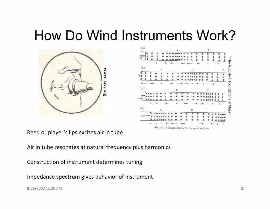
How Do Wind Instruments Work?
Reed or player’s lips excites air in tube
Air in tube resonates at natural frequency plus harmonics
Construction of instrument determines tuning
Impedance spectrum gives behavior of instrument
www.navy.org
“The Acoustical Foundations of M
usic”
8/25/2007 11:20 AM 48/25/2007 4
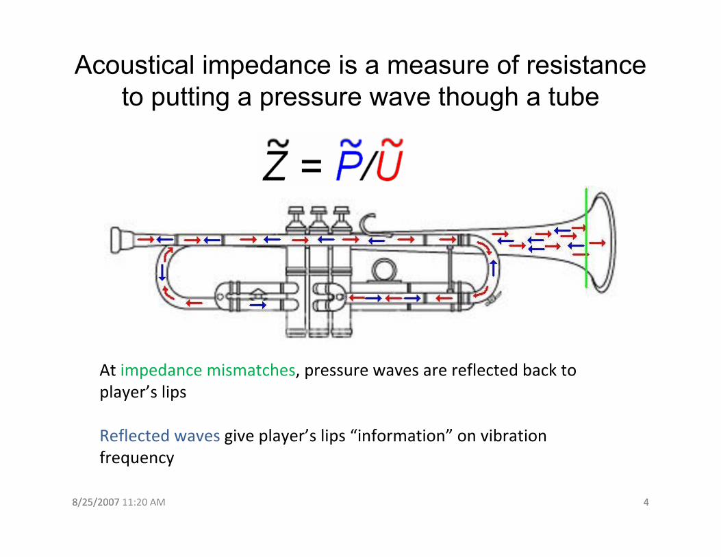
Acoustical impedance is a measure of resistance to putting a pressure wave though a tube
At impedance mismatches, pressure waves are reflected back to player’s lips
Reflected waves give player’s lips “information” on vibration frequency
8/25/2007 11:20 AM 58/25/2007 5
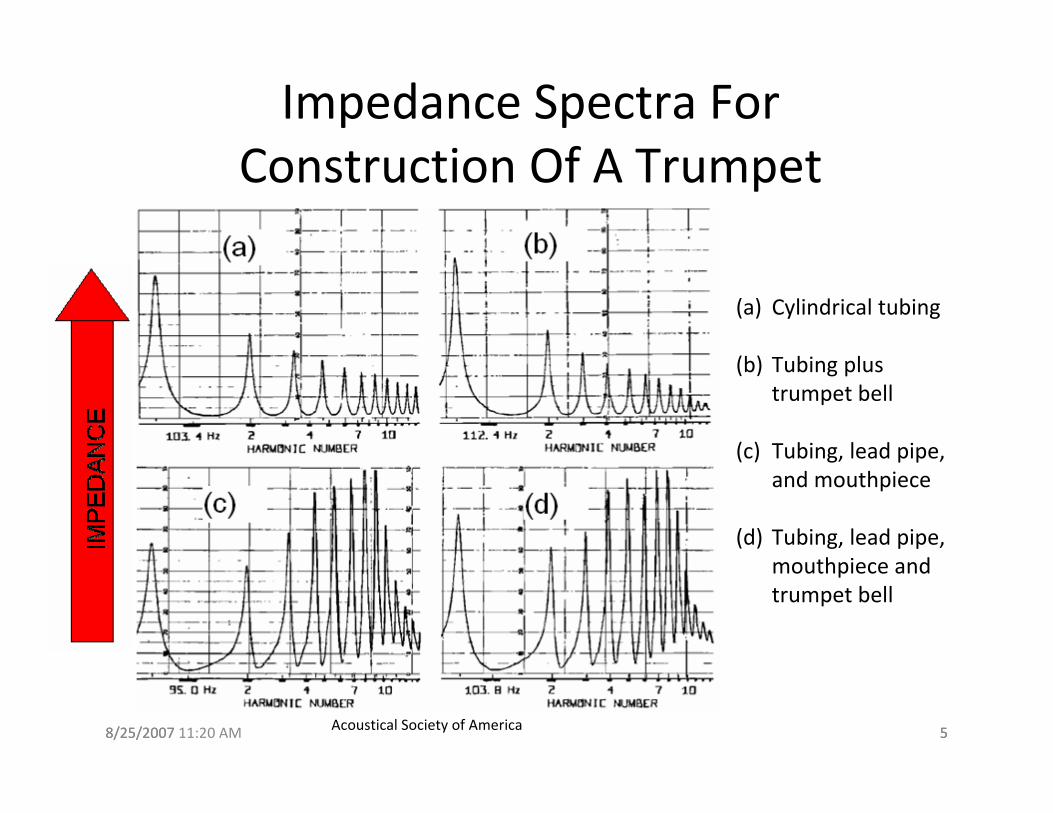
Impedance Spectra For Construction Of A Trumpet
(a) Cylindrical tubing
(b) Tubing plus trumpet bell
(c) Tubing, lead pipe, and mouthpiece
(d) Tubing, lead pipe, mouthpiece and trumpet bell
Acoustical Society of America
8/25/2007 11:20 AM 68/25/2007 6
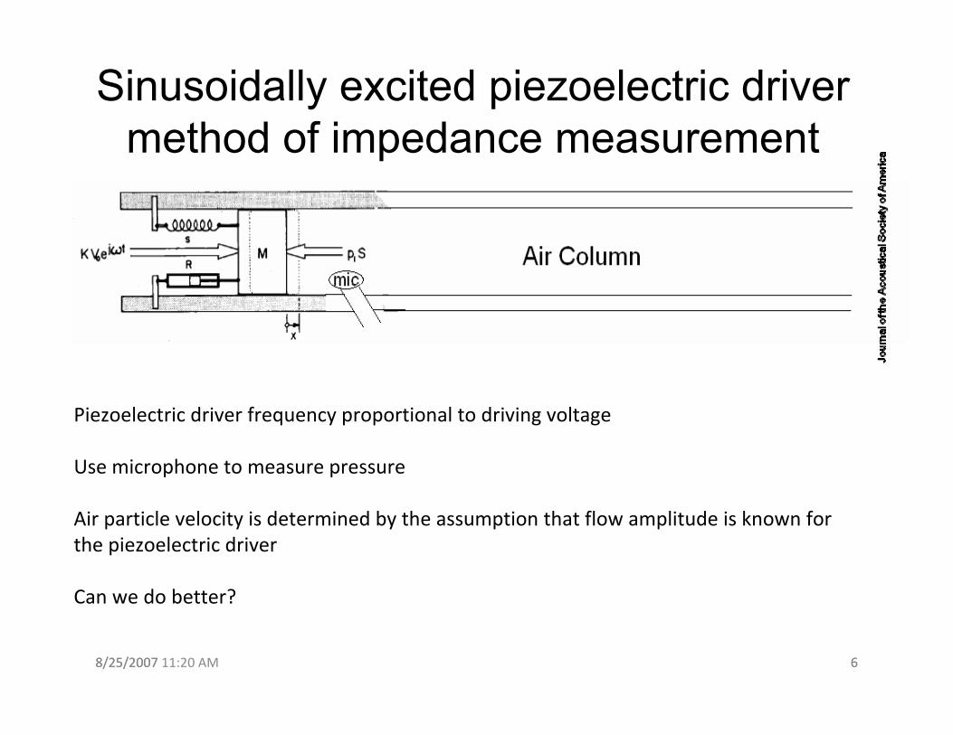
Sinusoidally excited piezoelectric driver method of impedance measurement
Piezoelectric driver frequency proportional to driving voltage
Use microphone to measure pressure
Air particle velocity is determined by the assumption that flow amplitude is known for the piezoelectric driver
Can we do better?
8/25/2007 11:20 AM 78/25/2007 7
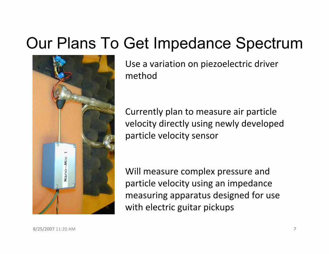
Our Plans To Get Impedance SpectrumUse a variation on piezoelectric driver method
Currently plan to measure air particle velocity directly using newly developed particle velocity sensor
Will measure complex pressure and particle velocity using an impedance measuring apparatus designed for use with electric guitar pickups
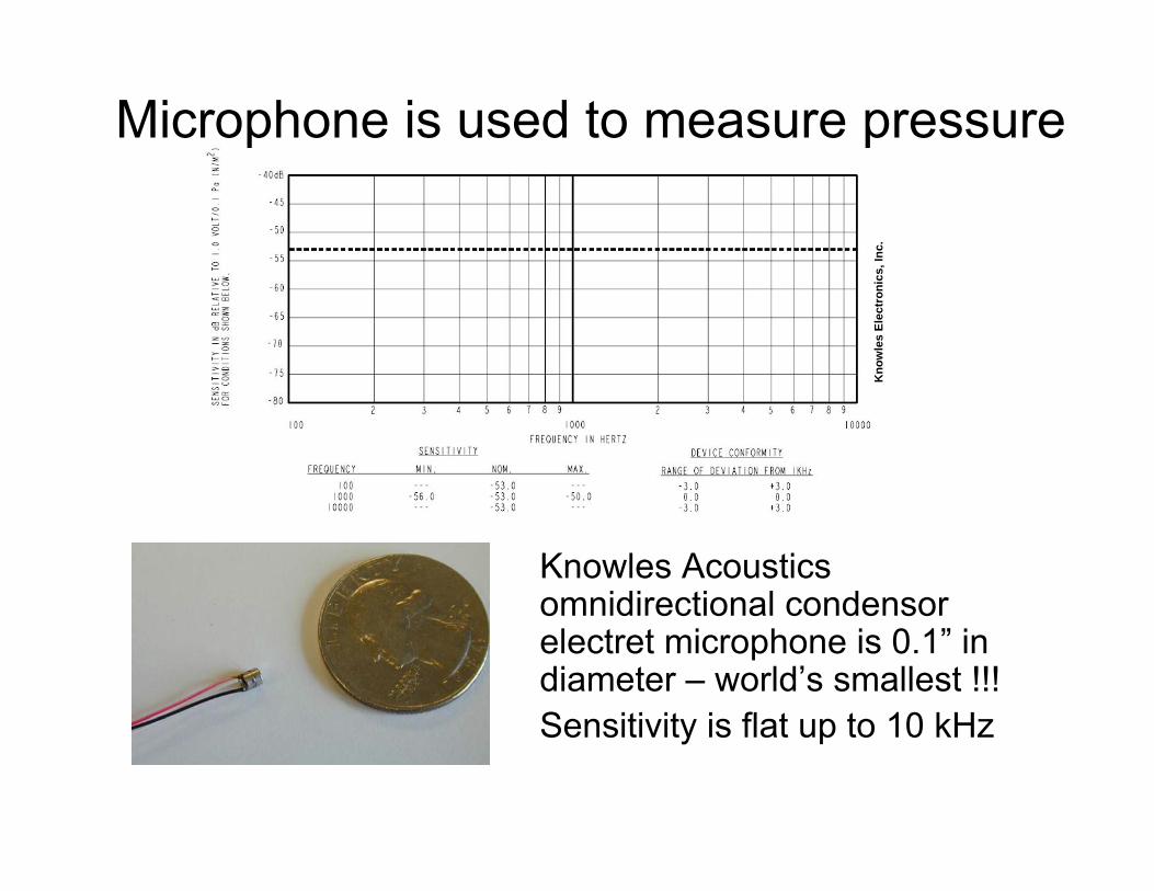
Microphone is used to measure pressure
Knowles Acoustics omnidirectional condensorelectret microphone is 0.1” in diameter – world’s smallest !!! Sensitivity is flat up to 10 kHz
Kno
wle
s El
ectr
onic
s, In
c.
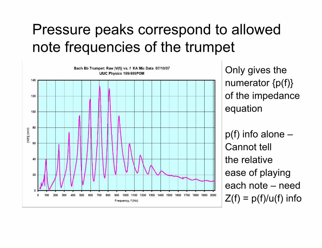
Pressure peaks correspond to allowed note frequencies of the trumpet
Only gives the numerator {p(f)} of the impedance equation
p(f) info alone –Cannot tell the relative ease of playing each note – needZ(f) = p(f)/u(f) info
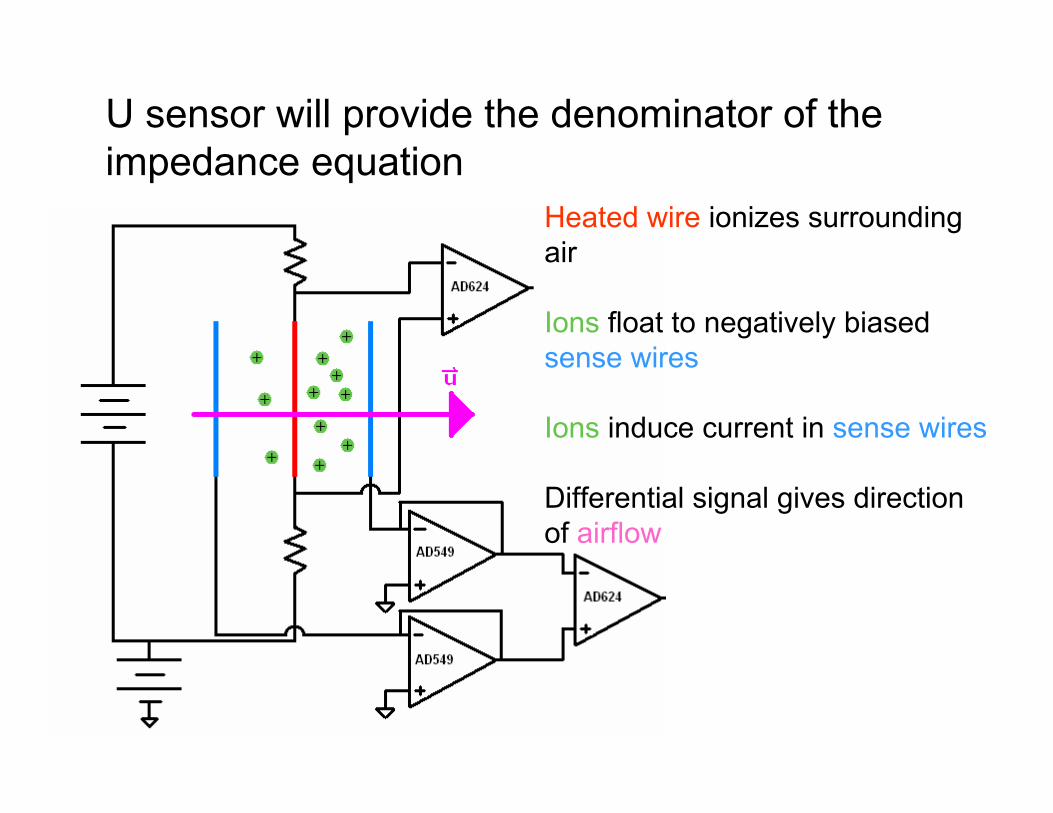
U sensor will provide the denominator of the impedance equation
Heated wire ionizes surrounding air
Ions float to negatively biased sense wires
Ions induce current in sense wires
Differential signal gives direction of airflow
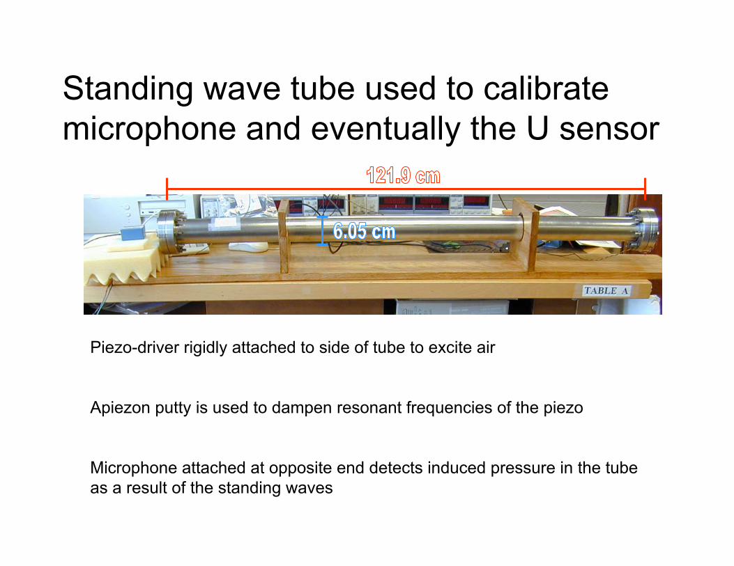
Standing wave tube used to calibrate microphone and eventually the U sensor
Piezo-driver rigidly attached to side of tube to excite air
Apiezon putty is used to dampen resonant frequencies of the piezo
Microphone attached at opposite end detects induced pressure in the tube as a result of the standing waves
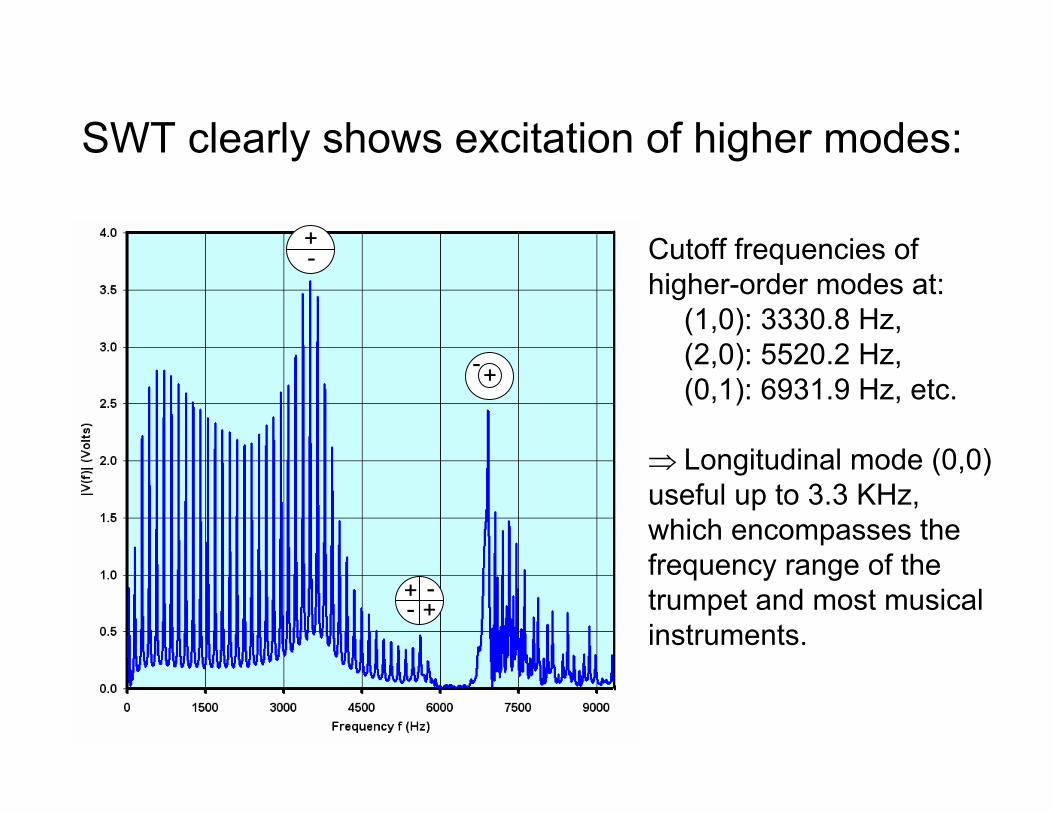
Cutoff frequencies of higher-order modes at:
(1,0): 3330.8 Hz, (2,0): 5520.2 Hz, (0,1): 6931.9 Hz, etc.
⇒ Longitudinal mode (0,0)useful up to 3.3 KHz,which encompasses the frequency range of thetrumpet and most musical instruments.
+ -+
+
-
-
SWT clearly shows excitation of higher modes:
+-
8/25/2007 11:20 AM 138/25/2007 13
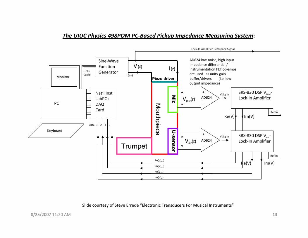
The UIUC Physics 498POM PC‐Based Pickup Impedance Measuring System:
PC
Nat’l Inst LabPC+ DAQ Card
Sine‐Wave Function GeneratorGPIB
CableMonitor
+
−AD624
+
−
AD624
AD624 low‐noise, high input impedance differential / instrumentation FET op‐amps are used as unity‐gain buffer/drivers (i.e. low output impedance)
SRS‐830 DSP Vair‐Lock‐In Amplifier
Vmic(t)
Ref In
Ref In
SRS‐830 DSP Vmic‐Lock‐In Amplifier
V Sig In
V Sig In
Gnd
Lock‐In Amplifier Reference Signal
Re(V) Im(V)
Re(V) Im(V)
ADC 3 2 1 0
Re(Vmic)
Im(Vmic)
Re(Vair)
Im(Vair)
Keyboard
V (t)
Slide courtesy of Steve Errede “Electronic Transducers For Musical InstrumentsElectronic Transducers For Musical Instruments””
Vair(t)
Mouthpiece
Piezo-driver
Mic
U-sensorTrumpet
I (t)
8/25/2007 11:20 AM 148/25/2007 14
Example Results:• Experiment covers entire human audio range
(20 Hz → 20,000 Hz in 10 Hz steps)
• Program takes ~3 hours to run (~5 s wait for lock-ins to settle/frequency point)
• Results plotted on 21 separate on-line graphs (Re(Z) vs. f, Im(Z) vs. f, Re(P) vs. f, Re(U) vs. f, etc…, writes out data file for offline analysis…)
8/25/2007 11:20 AM 158/25/2007 15
Long-term Plans:• Construction of air particle velocity sensor
• “Universal” apparatus: can be used for measuring complex Z = p/u and I = pu for anywind instrument, as well as for arbitrary sound fields!
Questions? Email- [email protected]
Special thanks to Prof. Steve Errede.


![SCORE IN C - Amos Elkana [Composer]Sop. Sax. Alto Sax. Ten. Sax. Bari. Sax. Mar. Vln. 85 Sop. Sax. Alto Sax. Ten. Sax. Bari. Sax. Mar. Pno. Vln. 88 pp pp &, , &, ,?, ,?, , & & > >](https://img.pdfslide.net/doc/110x75/60a8fffc38c9f319c0407756/score-in-c-amos-elkana-composer-sop-sax-alto-sax-ten-sax-bari-sax-mar.jpg)