Embed Size (px)
DESCRIPTION
timber
Citation preview
TIMBER FRAMING 74 • DECEMBER 2004#
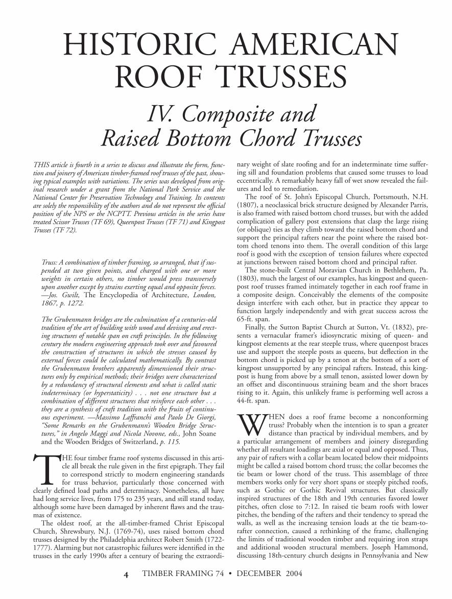
HISTORIC AMERICANROOF TRUSSES
IV. Composite and Raised Bottom Chord Trusses
Truss: A combination of timber framing, so arranged, that if sus-pended at two given points, and charged with one or moreweights in certain others, no timber would press transverselyupon another except by strains exerting equal and opposite forces. —Jos. Gwilt, The Encyclopedia of Architecture, London,1867, p. 1272.
The Grubenmann bridges are the culmination of a centuries-oldtradition of the art of building with wood and devising and erect-ing structures of notable span on craft principles. In the followingcentury the modern engineering approach took over and favouredthe construction of structures in which the stresses caused byexternal forces could be calculated mathematically. By contrastthe Grubenmann brothers apparently dimensioned their struc-tures only by empirical methods; their bridges were characterizedby a redundancy of structural elements and what is called staticindeterminacy (or hyperstaticity) . . . not one structure but acombination of different structures that reinforce each other . . .they are a synthesis of craft tradition with the fruits of continu-ous experiment. —Massimo Laffranchi and Paolo De Giorgi,“Some Remarks on the Grubenmann’s Wooden Bridge Struc-tures,” in Angelo Maggi and Nicola Novone, eds., John Soaneand the Wooden Bridges of Switzerland, p. 115.
THE four timber frame roof systems discussed in this arti-cle all break the rule given in the first epigraph. They failto correspond strictly to modern engineering standardsfor truss behavior, particularly those concerned with
clearly defined load paths and determinacy. Nonetheless, all havehad long service lives, from 175 to 235 years, and still stand today,although some have been damaged by inherent flaws and the trau-mas of existence.
The oldest roof, at the all-timber-framed Christ EpiscopalChurch, Shrewsbury, N.J. (1769-74), uses raised bottom chordtrusses designed by the Philadelphia architect Robert Smith (1722-1777). Alarming but not catastrophic failures were identified in thetrusses in the early 1990s after a century of bearing the extraordi-
nary weight of slate roofing and for an indeterminate time suffer-ing sill and foundation problems that caused some trusses to loadeccentrically. A remarkably heavy fall of wet snow revealed the fail-ures and led to remediation.
The roof of St. John’s Episcopal Church, Portsmouth, N.H.(1807), a neoclassical brick structure designed by Alexander Parris,is also framed with raised bottom chord trusses, but with the addedcomplication of gallery post extensions that clasp the large rising(or oblique) ties as they climb toward the raised bottom chord andsupport the principal rafters near the point where the raised bot-tom chord tenons into them. The overall condition of this largeroof is good with the exception of tension failures where expectedat junctions between raised bottom chord and principal rafter.
The stone-built Central Moravian Church in Bethlehem, Pa.(1803), much the largest of our examples, has kingpost and queen-post roof trusses framed intimately together in each roof frame ina composite design. Conceivably the elements of the compositedesign interfere with each other, but in practice they appear tofunction largely independently and with great success across the65-ft. span.
Finally, the Sutton Baptist Church at Sutton, Vt. (1832), pre-sents a vernacular framer’s idiosyncratic mixing of queen- andkingpost elements at the rear steeple truss, where queenpost bracesuse and support the steeple posts as queens, but deflection in thebottom chord is picked up by a tenon at the bottom of a sort ofkingpost unsupported by any principal rafters. Instead, this king-post is hung from above by a small tenon, assisted lower down byan offset and discontinuous straining beam and the short bracesrising to it. Again, this unlikely frame is performing well across a44-ft. span.
WHEN does a roof frame become a nonconformingtruss? Probably when the intention is to span a greaterdistance than practical by individual members, and by
a particular arrangement of members and joinery disregardingwhether all resultant loadings are axial or equal and opposed. Thus,any pair of rafters with a collar beam located below their midpointsmight be called a raised bottom chord truss; the collar becomes thetie beam or lower chord of the truss. This assemblage of threemembers works only for very short spans or steeply pitched roofs,such as Gothic or Gothic Revival structures. But classicallyinspired structures of the 18th and 19th centuries favored lowerpitches, often close to 7:12. In raised tie beam roofs with lowerpitches, the bending of the rafters and their tendency to spread thewalls, as well as the increasing tension loads at the tie beam-to-rafter connection, caused a rethinking of the frame, challengingthe limits of traditional wooden timber and requiring iron strapsand additional wooden structural members. Joseph Hammond,discussing 18th-century church designs in Pennsylvania and New
THIS article is fourth in a series to discuss and illustrate the form, func-tion and joinery of American timber-framed roof trusses of the past, show-ing typical examples with variations. The series was developed from orig-inal research under a grant from the National Park Service and theNational Center for Preservation Technology and Training. Its contentsare solely the responsibility of the authors and do not represent the officialposition of the NPS or the NCPTT. Previous articles in the series havetreated Scissor Trusses (TF 69), Queenpost Trusses (TF 71) and KingpostTrusses (TF 72).
TIMBER FRAMING 74 • DECEMBER 2004 $
Jersey, traced the evolution of the low-pitch, long-span raised bot-tom chord truss from Christopher Wren’s design for St. Paul’sCathedral in London (1706) through the various editions ofFrancis Price’s The British Carpenter (first published 1733), to thePhiladelphia area churches of Robert Smith, including St. Paul’sEpiscopal (1760-61) with its span of 65 ft. (Hammond, 16). Asimilar design, though with less iron reinforcement, shows uphundreds of miles to the northwest at the Cazenovia, N.Y., FirstPresbyterian Church by 1805.
Truss assemblies composed of two truss forms are not histori-cally unusual. Numerous 18th- and 19th-century church roofs andwooden bridges employ queenpost trusses with a kingpost orkingrod captured in the middle panel, and with struts rising fromthe queenposts to stiffen the straining beam where the kingroddescends from it. Indeed, this same composite truss shows upmuch earlier in Palladio’s 16th-century bridge designs and again inThe British Carpenter, where in some cases a kingpost truss issuperimposed above the queenpost truss with the kingpost sus-pending the straining beam, incidentally providing a peak for theroof. In numerous surviving bridge trusses of this compositedesign, all the elements, whether tension or compression, appear tobe loaded, and we can conclude they are contributing to the over-all functioning of the truss (Figs. 1 and 2).
In long-span bridge framing, it is common for a timber or plankarch to be superimposed or integrally framed into (typically) amultiple kingpost truss, as in the Burr Arch designs or the greatLong Truss variant at North Blenheim, N.Y., but the only exampleI know of arch trussing in a church roof is the polygonal arch con-structed in 1752 in the Reformed Church at Grub, Switzerland,and that truss runs longitudinally in the church, interacting with aseries of transverse roof frames (Maggi and Navone, 124).
However, some trusses do have superfluous members thatunder service conditions remain unloaded or even loose, and fromthese we can infer on the part of the designer an unclear under-standing of load paths and truss behavior. The powerful truss at
the Central Moravian Church is one of these, where field exami-nation discloses that the struts rising from kingpost feet to queen-post heads and from queenpost feet to the central joggle of thekingpost are randomly tight and loose, suggesting that each of theinterpenetrated truss types is managing to work alone or in paral-lel with the other.
English and Continental sources show us numerous roof framesthat either don’t qualify as trusses at all, for example queenpost sys-tems that depend entirely upon a stout cambered tie beam for sta-bility, or kingpost systems equipped with numerous braces thatlook useful when the frame is lying on the ground but becomeloose as soon as the truss is stood up bearing only its own weight.Some of these apparently superfluous members may earn theirkeep when the roof is loaded eccentrically by heavy snow or highwind, much as the crossing braces in the central panels of bridgetrusses take turns being loaded when a moving vehicle shifts thecenter of the bridge slightly and causes a reversal of stresses aroundthe midpoint.
The examination of church attics of notable span in easternNorth America (qualified by the small percentage it is possible tosee in one lifetime) generally reveals trusses so rationalized that wesuspect the builders were very experienced and endowed with goodstructural instincts, or they were in possession of builders’ guidesthat included sound truss designs. Exceptions exist. Puny rakingstruts or ties rising from tie beam to rafter in such roofs as at theStrafford, Vt., Town House (1799) or at the Windham, Vt.,Congregational Church (1801), discussed in Part III of this series(see TF 72), are archaic holdovers that play no role or only a tinyone in the functioning of these otherwise completely realizedtrusses. Another puzzling example is the kingpost truss roof of the1829 Newbury, Vt., Methodist Church, where 9x9 vertical mem-bers parallel the kingpost at the quarter points of the span, unsup-ported by struts or bracing, seemingly awaiting (nonexistent)gallery posts below to help them prop the midspan of the rafters.Without the gallery posts, these unsupported posts at Newburyserve merely to load and deflect the bottom chord at a point 10 ft.distant from the kingpost tension joint (Fig. 3).
All of the four roof trusses discussed below have members orjoinery that lead contemporary observers to shake their heads andwonder why such framing choices were made, and how such non-conforming trusses actually work. By examining these trusses forwhat is loose or open, broken or heavily compressed, by enteringthin rulers into supposed bearing surfaces of joints, by strikingbraces and struts with mallets to hear how they ring, we can hopeto find out where the forces run.
Fig. 3. Naïve truss at Newbury, Vermont, Methodist Church, 1829.Apparent queenpost merely adds unwanted load to truss chord.
Ken Rower
Fig. 1. Kingpost truss superimposed above queenpost truss, from PlateI of Francis Price, The British Carpenter, 1733.
Fig. 2. Queenpost truss with kingpost captured in middle panel,shown in Palladio’s Four Books (1570), from a 1738 London edition.
TIMBER FRAMING 74 • DECEMBER 2004%
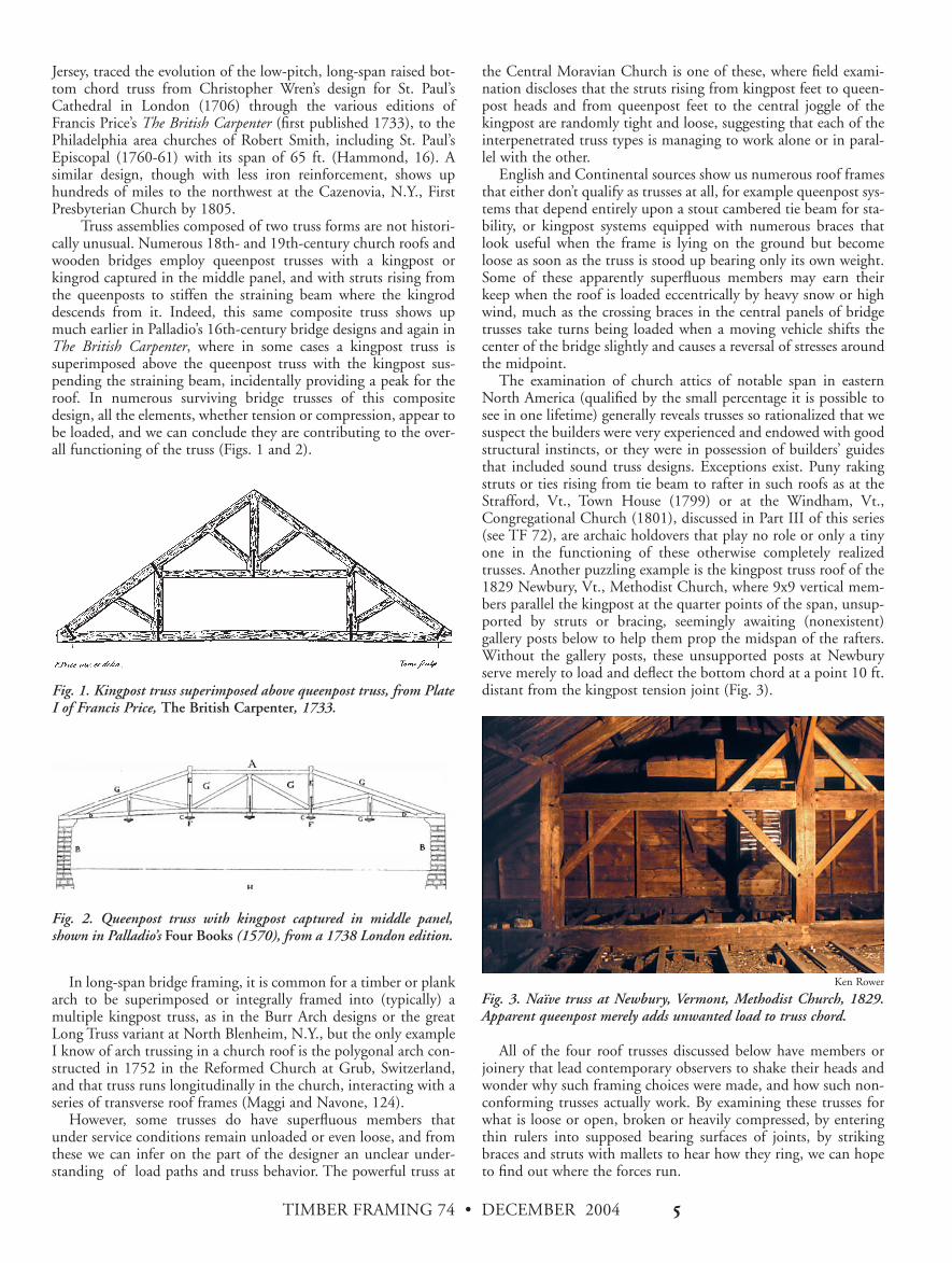
CENTRAL MORAVIAN CHURCH, Bethlehem, Pa.(1803-1806). This immense church is crowned by a mostcommodious attic, spacious and well floored, permitting
researchers to walk about upright (an unusual liberty) among ten65-ft.-span trusses spaced a nominal 10 ft. on center. In the mid-dle of the building, rather than at one end, the sleepers for thebraces and posts of the sturdy cupola spread themselves across thebottom chords of six trusses. The entire ensemble of roof framingbears on 17x6 timber plates over mortared and parged rubble stonewalls, typically 27 in. thick.
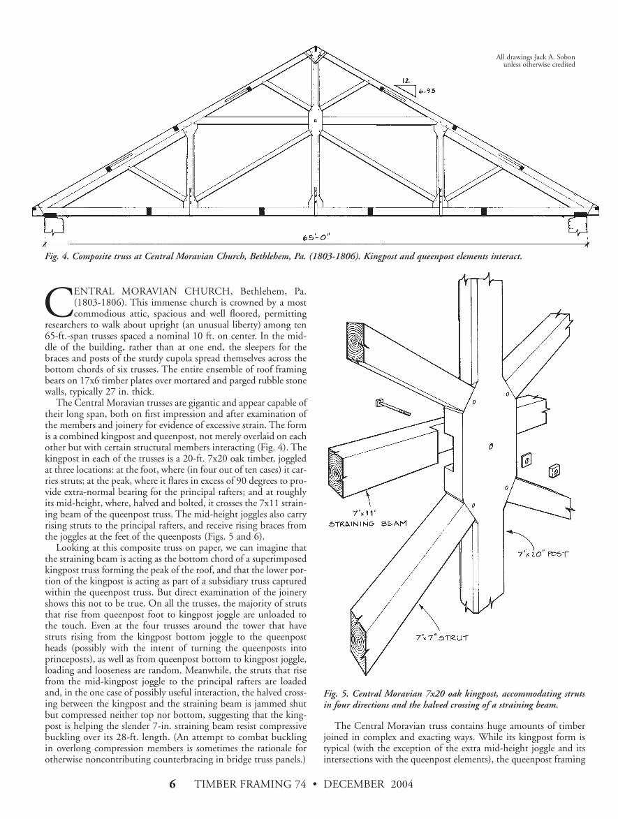
The Central Moravian trusses are gigantic and appear capable oftheir long span, both on first impression and after examination ofthe members and joinery for evidence of excessive strain. The formis a combined kingpost and queenpost, not merely overlaid on eachother but with certain structural members interacting (Fig. 4). Thekingpost in each of the trusses is a 20-ft. 7x20 oak timber, joggledat three locations: at the foot, where (in four out of ten cases) it car-ries struts; at the peak, where it flares in excess of 90 degrees to pro-vide extra-normal bearing for the principal rafters; and at roughlyits mid-height, where, halved and bolted, it crosses the 7x11 strain-ing beam of the queenpost truss. The mid-height joggles also carryrising struts to the principal rafters, and receive rising braces fromthe joggles at the feet of the queenposts (Figs. 5 and 6).
Looking at this composite truss on paper, we can imagine thatthe straining beam is acting as the bottom chord of a superimposedkingpost truss forming the peak of the roof, and that the lower por-tion of the kingpost is acting as part of a subsidiary truss capturedwithin the queenpost truss. But direct examination of the joineryshows this not to be true. On all the trusses, the majority of strutsthat rise from queenpost foot to kingpost joggle are unloaded tothe touch. Even at the four trusses around the tower that havestruts rising from the kingpost bottom joggle to the queenpostheads (possibly with the intent of turning the queenposts intoprinceposts), as well as from queenpost bottom to kingpost joggle,loading and looseness are random. Meanwhile, the struts that risefrom the mid-kingpost joggle to the principal rafters are loadedand, in the one case of possibly useful interaction, the halved cross-ing between the kingpost and the straining beam is jammed shutbut compressed neither top nor bottom, suggesting that the king-post is helping the slender 7-in. straining beam resist compressivebuckling over its 28-ft. length. (An attempt to combat bucklingin overlong compression members is sometimes the rationale forotherwise noncontributing counterbracing in bridge truss panels.)
The Central Moravian truss contains huge amounts of timberjoined in complex and exacting ways. While its kingpost form istypical (with the exception of the extra mid-height joggle and itsintersections with the queenpost elements), the queenpost framing
Fig. 4. Composite truss at Central Moravian Church, Bethlehem, Pa. (1803-1806). Kingpost and queenpost elements interact.
Fig. 5. Central Moravian 7x20 oak kingpost, accommodating strutsin four directions and the halved crossing of a straining beam.
All drawings Jack A. Sobon unless otherwise credited
TIMBER FRAMING 74 • DECEMBER 2004 &
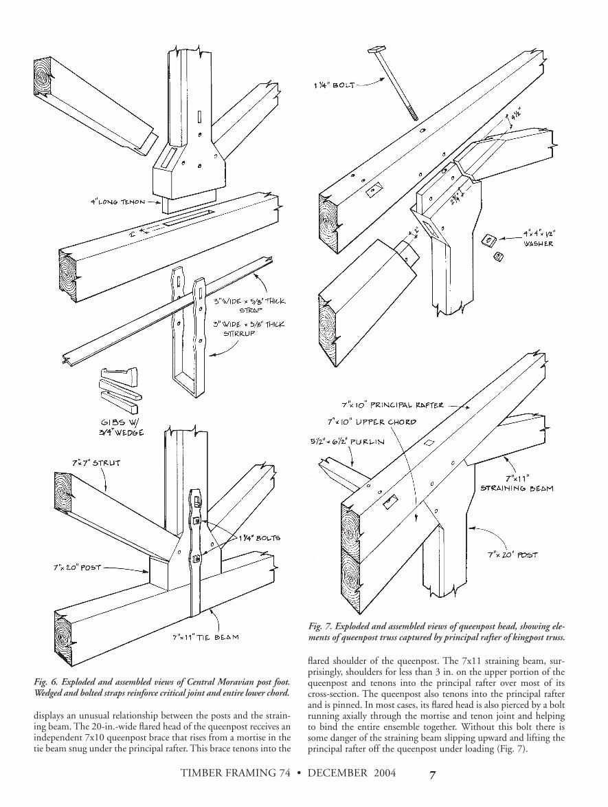
displays an unusual relationship between the posts and the strain-ing beam. The 20-in.-wide flared head of the queenpost receives anindependent 7x10 queenpost brace that rises from a mortise in thetie beam snug under the principal rafter. This brace tenons into the
flared shoulder of the queenpost. The 7x11 straining beam, sur-prisingly, shoulders for less than 3 in. on the upper portion of thequeenpost and tenons into the principal rafter over most of itscross-section. The queenpost also tenons into the principal rafterand is pinned. In most cases, its flared head is also pierced by a boltrunning axially through the mortise and tenon joint and helpingto bind the entire ensemble together. Without this bolt there issome danger of the straining beam slipping upward and lifting theprincipal rafter off the queenpost under loading (Fig. 7).
Fig. 6. Exploded and assembled views of Central Moravian post foot.Wedged and bolted straps reinforce critical joint and entire lower chord.
Fig. 7. Exploded and assembled views of queenpost head, showing ele-ments of queenpost truss captured by principal rafter of kingpost truss.
TIMBER FRAMING 74 • DECEMBER 2004'
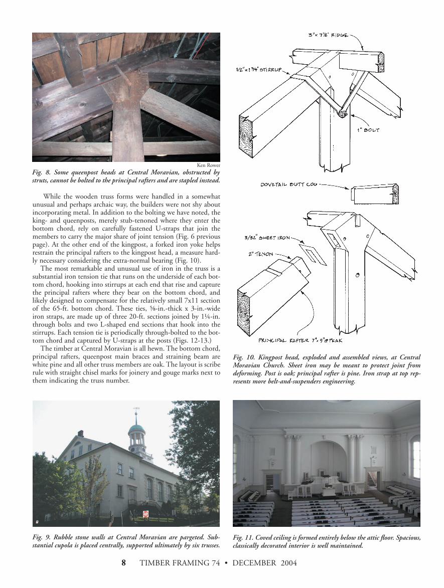
While the wooden truss forms were handled in a somewhatunusual and perhaps archaic way, the builders were not shy aboutincorporating metal. In addition to the bolting we have noted, theking- and queenposts, merely stub-tenoned where they enter thebottom chord, rely on carefully fastened U-straps that join themembers to carry the major share of joint tension (Fig. 6 previouspage). At the other end of the kingpost, a forked iron yoke helpsrestrain the principal rafters to the kingpost head, a measure hard-ly necessary considering the extra-normal bearing (Fig. 10).
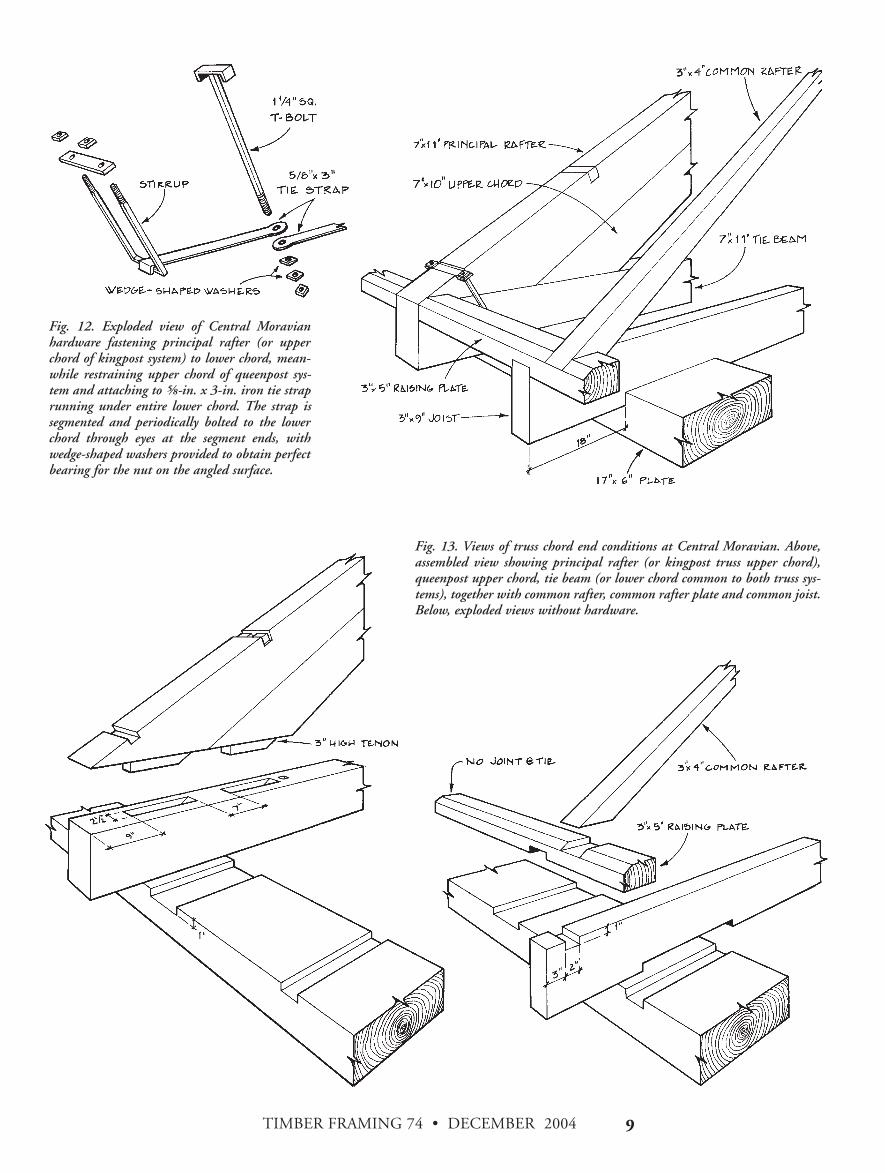
The most remarkable and unusual use of iron in the truss is asubstantial iron tension tie that runs on the underside of each bot-tom chord, hooking into stirrups at each end that rise and capturethe principal rafters where they bear on the bottom chord, andlikely designed to compensate for the relatively small 7x11 sectionof the 65-ft. bottom chord. These ties, )-in.-thick x 3-in.-wideiron straps, are made up of three 20-ft. sections joined by 1(-in.through bolts and two L-shaped end sections that hook into thestirrups. Each tension tie is periodically through-bolted to the bot-tom chord and captured by U-straps at the posts (Figs. 12-13.)
The timber at Central Moravian is all hewn. The bottom chord,principal rafters, queenpost main braces and straining beam arewhite pine and all other truss members are oak. The layout is scriberule with straight chisel marks for joinery and gouge marks next tothem indicating the truss number.
Fig. 10. Kingpost head, exploded and assembled views, at CentralMoravian Church. Sheet iron may be meant to protect joint fromdeforming. Post is oak; principal rafter is pine. Iron strap at top rep-resents more belt-and-suspenders engineering.
Fig. 11. Coved ceiling is formed entirely below the attic floor. Spacious,classically decorated interior is well maintained.
Fig. 9. Rubble stone walls at Central Moravian are pargeted. Sub-stantial cupola is placed centrally, supported ultimately by six trusses.
Fig. 8. Some queenpost heads at Central Moravian, obstructed bystruts, cannot be bolted to the principal rafters and are stapled instead.
Ken Rower
TIMBER FRAMING 74 • DECEMBER 2004 (
Fig. 12. Exploded view of Central Moravianhardware fastening principal rafter (or upperchord of kingpost system) to lower chord, mean-while restraining upper chord of queenpost sys-tem and attaching to !-in. x 3-in. iron tie straprunning under entire lower chord. The strap issegmented and periodically bolted to the lowerchord through eyes at the segment ends, withwedge-shaped washers provided to obtain perfectbearing for the nut on the angled surface.
Fig. 13. Views of truss chord end conditions at Central Moravian. Above,assembled view showing principal rafter (or kingpost truss upper chord),queenpost upper chord, tie beam (or lower chord common to both truss sys-tems), together with common rafter, common rafter plate and common joist.Below, exploded views without hardware.
TIMBER FRAMING 74 • DECEMBER 2004)*
CHRIST EPISCOPAL CHURCH, Shrewsbury, N. J. (1769).Three others of colonial architect Robert Smith’s docu-mented church commissions also employed such a raised
bottom chord truss to support the roof (see TF 73). At St. Peter’sEpiscopal (1771) in nearby Freehold is another almost identicalsurviving truss that probably can be attributed to Smith. The trussdesign appears in Price’s The British Carpenter by 1733, andChristopher Wren used it as early as 1706. A great many medievalroof frames employed the collared rafter pair with braces risingfrom rafter to collar, but the change that turns it into a sort of trussis the introduction of oblique ties that bear on the wall andattempt to restrain the load of the rafters in the fashion of a typi-cal truss bottom chord. These ties rise and join the raised tie beamnear its midpoint, where an attempt is made to produce a strongtension joint through the use of long mortise and tenon joints withmultiple pegs, often reinforced by iron straps (Fig. 14).
A further recognition of the high tensile forces developed by thisnonconforming truss, particularly when used in a low-pitch roof(Shrewsbury is slightly under 7:12), is implied by the appearanceof iron straps at a great many of the joints in every printed illustra-tion of the form. The 1786 Rules for Measuring and Valuing House-Carpenters Work promulgated by The Carpenters’ Company ofPhiladelphia depicts the truss with extensive iron work on Plate VI,and describes it using the curious term “hammerbeam” for theoblique rising ties, a term also used by Smith and Price. The sametruss design appears in Nicholson’s New Carpenters Guide (Plate45) as late as 1837, and in Thomas Tredgold’s Elementary Principlesof Carpentry (Plate 9) in that same year. Tredgold, while praisingPrice’s work in general, criticizes this truss, particularly for the highstrains developed by the oblique disposition of the “beams”(Prices’s “hammerbeams” or my “oblique ties”), and points outdefects such as the excessive number of joints and the “certainty ofthe considerable change of figure from flexure” (Tredgold, 93).
Among modern commentators, David Yeomans, author of TheTrussed Roof, also finds “hammerbeam” for the oblique tie not thecustomary use for the term, and relates that “in spite of the appar-ent weakness of the raised tie beam arrangement, in England itremained the standard solution to the high vaulted ceiling through-out the 18th century” (Yeomans, 130). The late Cecil Hewett, inEnglish Cathedral and Monastic Carpentry, refers to the truss overthe west portico of St. Paul's as “a king-post with raking strutdesign . . . mounted upon collars with which the other compo-nents form built camber beams” (Hewett, 69).
The eight trusses (excluding end walls) at Shrewsbury span 38ft. and are spaced between 5 ft. 10 in. and 8 ft. 7 in. apart, reflect-ing window positions in the supporting timber-framed walls.Combined with the diagonal bracing rising from wall post tooblique tie, the trusses collectively provide the rough form for avaulted ceiling, the usual reason for employing the raised bottom
chord. The scribe-ruled timber frame is composed of mixed whiteand red oak timber, most members hewn but some braces andcommon rafters vertically sawn, and fastened with both *-in. and1(-in. pins. The timber-framed walls of this church are not solid-sheathed but carry spaced let-in nailers to which long white cedarshakes are affixed, in the manner of several other 18th-centuryNew Jersey churches I have examined. Shrewsbury is the only oneof Smith’s churches to employ the raised bottom chord truss unac-companied by the mass of a masonry wall.
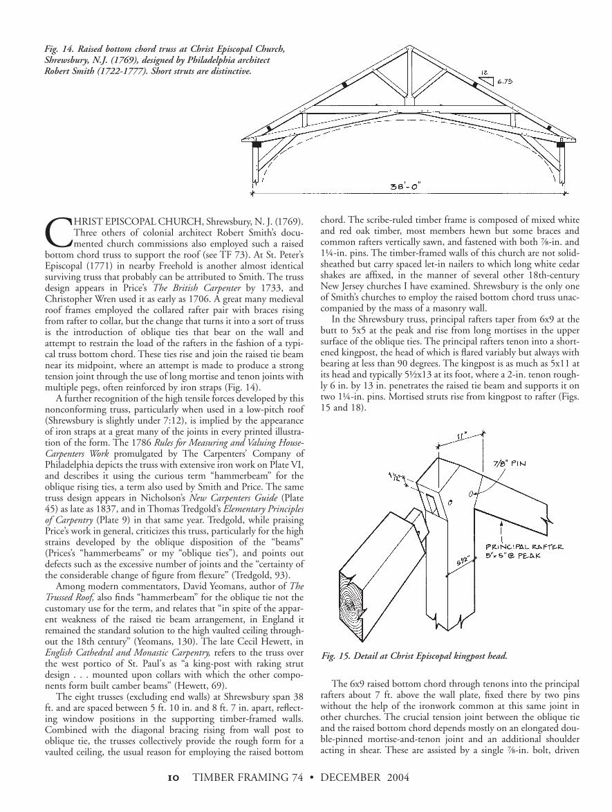
In the Shrewsbury truss, principal rafters taper from 6x9 at thebutt to 5x5 at the peak and rise from long mortises in the uppersurface of the oblique ties. The principal rafters tenon into a short-ened kingpost, the head of which is flared variably but always withbearing at less than 90 degrees. The kingpost is as much as 5x11 atits head and typically 5+x13 at its foot, where a 2-in. tenon rough-ly 6 in. by 13 in. penetrates the raised tie beam and supports it ontwo 1(-in. pins. Mortised struts rise from kingpost to rafter (Figs.15 and 18).
The 6x9 raised bottom chord through tenons into the principalrafters about 7 ft. above the wall plate, fixed there by two pinswithout the help of the ironwork common at this same joint inother churches. The crucial tension joint between the oblique tieand the raised bottom chord depends mostly on an elongated dou-ble-pinned mortise-and-tenon joint and an additional shoulderacting in shear. These are assisted by a single *-in. bolt, driven
Fig. 14. Raised bottom chord truss at Christ Episcopal Church,Shrewsbury, N.J. (1769), designed by Philadelphia architect Robert Smith (1722-1777). Short struts are distinctive.
Fig. 15. Detail at Christ Episcopal kingpost head.
TIMBER FRAMING 74 • DECEMBER 2004 ))
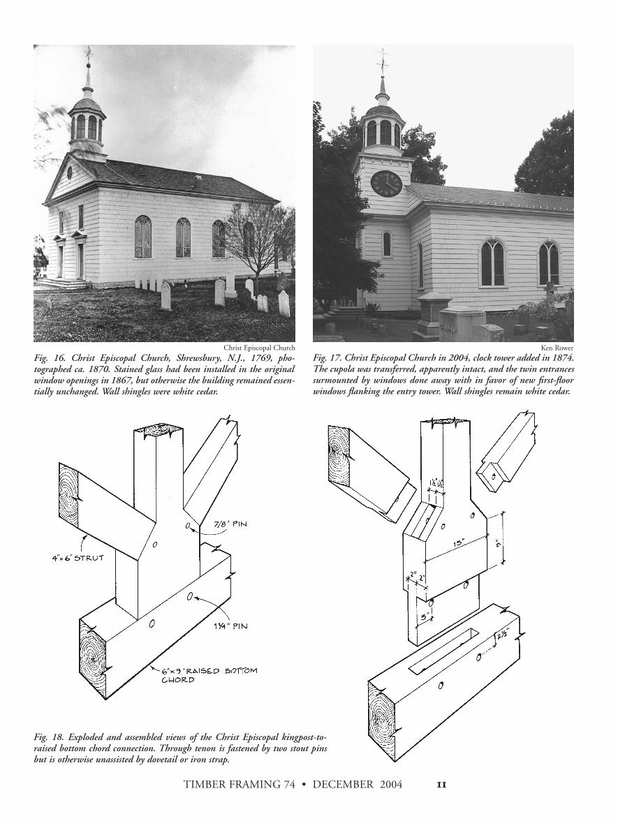
Fig. 18. Exploded and assembled views of the Christ Episcopal kingpost-to-raised bottom chord connection. Through tenon is fastened by two stout pinsbut is otherwise unassisted by dovetail or iron strap.
Fig. 16. Christ Episcopal Church, Shrewsbury, N.J., 1769, pho-tographed ca. 1870. Stained glass had been installed in the originalwindow openings in 1867, but otherwise the building remained essen-tially unchanged. Wall shingles were white cedar.
Fig. 17. Christ Episcopal Church in 2004, clock tower added in 1874.The cupola was transferred, apparently intact, and the twin entrancessurmounted by windows done away with in favor of new first-floorwindows flanking the entry tower. Wall shingles remain white cedar.
Ken RowerChrist Episcopal Church
TIMBER FRAMING 74 • DECEMBER 2004)!
from the bottom of the tie and clinched around a short section ofwooden pin on top of the chord (Figs. 19-21).
Most designs for this joint, including the 1786 Philadelphia rulebook plate and the Freehold drawing (Hammond, 21), featurebolts and a steel yoke that links the oblique ties, the raised chordand the kingpost, in recognition of the trouble likely to occur herewhere tension is not carried in a straight line.
The term “raised bottom chord” probably should not refer mere-ly to the horizontal member in this system. The functional bottomchord—that is, the principal wall-to-wall tension member—reallycomprises the two oblique ties and a middle section of the raisedchord, giving an arched three-piece bottom chord. The task ofkeeping this arched chord from stretching and flattening falls to itsjoinery, which is difficult to make adequate in wood, and to thekingpost that suspends the middle section of the chord.
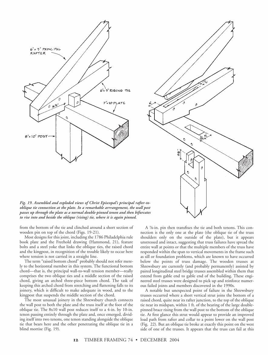
The most unusual joinery in the Shrewsbury church connectsthe wall post to both the plate and the truss itself at the foot of theoblique tie. The 8x10 wall post reduces itself to a 4-in. by 10-in.tenon passing entirely through the plate and, once emerged, divid-ing itself into two tenons, one tenon standing alongside the obliquetie that bears here and the other penetrating the oblique tie in ablind mortise (Fig. 19).
A *-in. pin then transfixes the tie and both tenons. This con-nection is the only one at the plate (the oblique tie of the trussshoulders only on the outside of the plate), but it appearsunstressed and intact, suggesting that truss failures have spread theentire wall at points or that the multiple members of the truss haveresponded within the span to vertical movements in the frame suchas sill or foundation problems, which are known to have occurredbelow the points of truss damage. The wooden trusses atShrewsbury are currently (and probably permanently) assisted bypaired longitudinal steel bridge trusses assembled within them thatextend from gable end to gable end of the building. These engi-neered steel trusses were designed to pick up and reinforce numer-ous failed joints and members discovered in the 1990s.
A notable but unexpected point of failure in the Shrewsburytrusses occurred where a short vertical strut joins the bottom of araised chord, quite near its rafter junction, to the top of the obliquetie near its midspan, within 1 ft. of the bearing of the large double-pinned brace rising from the wall post to the bottom of the obliquetie. At first glance this strut would appear to provide an improvedload path from rafter and collar to a point lower on the wall post(Fig. 22). But an oblique tie broke at exactly this point on the westside of one of the trusses. It appears that the truss can fail at this
Fig. 19. Assembled and exploded views of Christ Episcopal’s principal rafter-to-oblique tie connection at the plate. In a remarkable arrrangement, the wall postpasses up through the plate as a normal double-pinned tenon and then bifurcatesto rise into and beside the oblique (rising) tie, where it is again pinned.
TIMBER FRAMING 74 • DECEMBER 2004 )"
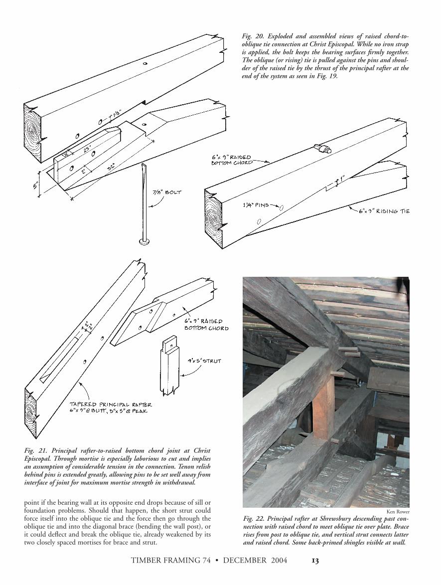
point if the bearing wall at its opposite end drops because of sill orfoundation problems. Should that happen, the short strut couldforce itself into the oblique tie and the force then go through theoblique tie and into the diagonal brace (bending the wall post), orit could deflect and break the oblique tie, already weakened by itstwo closely spaced mortises for brace and strut.
Fig. 20. Exploded and assembled views of raised chord-to-oblique tie connection at Christ Episcopal. While no iron strapis applied, the bolt keeps the bearing surfaces firmly together.The oblique (or rising) tie is pulled against the pins and shoul-der of the raised tie by the thrust of the principal rafter at theend of the system as seen in Fig. 19.
Fig. 21. Principal rafter-to-raised bottom chord joint at ChristEpiscopal. Through mortise is especially laborious to cut and impliesan assumption of considerable tension in the connection. Tenon relishbehind pins is extended greatly, allowing pins to be set well away frominterface of joint for maximum mortise strength in withdrawal.
Fig. 22. Principal rafter at Shrewsbury descending past con-nection with raised chord to meet oblique tie over plate. Bracerises from post to oblique tie, and vertical strut connects latterand raised chord. Some back-primed shingles visible at wall.
Ken Rower
TIMBER FRAMING 74 • DECEMBER 2004)#
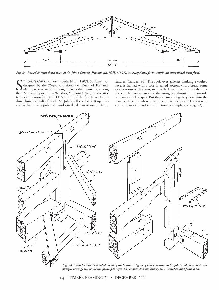
ST. JOHN’S CHURCH, Portsmouth, N.H. (1807). St. John’s wasdesigned by the 26-year-old Alexander Parris of Portland,Maine, who went on to design many other churches, among
them St. Paul’s Episcopal in Windsor, Vermont (1822), whose attictrusses are scissor-form (see TF 69). One of the first New Hamp-shire churches built of brick, St. John’s reflects Asher Benjamin’sand William Pain’s published works in the design of some exterior
features (Candee, 86). The roof, over galleries flanking a vaultednave, is framed with a sort of raised bottom chord truss. Somespecifications of this truss, such as the large dimensions of the tim-ber and the continuation of the rising ties almost to the outsidewall, imply a clear span. But the extension of gallery posts into theplane of the truss, where they intersect in a deliberate fashion withseveral members, renders its functioning complicated (Fig. 23).
Fig. 23. Raised bottom chord truss at St. John’s Church, Portsmouth, N.H. (1807), an exceptional form within an exceptional truss form.
Fig. 24. Assembled and exploded views of the laminated gallery post extension at St. John’s, where it clasps theoblique (rising) tie, while the principal rafter passes over and the gallery tie is strapped and pinned on.
TIMBER FRAMING 74 • DECEMBER 2004 )$
its lower chord’s tenoned junction with the principal rafters (Kelly,I, 303 and II, 86). In addition, the raised kingpost is supported byinner main braces that descend to the lower chord and bear overthe gallery posts. In such cases, because of their support, the tiebeam’s function as a bottom chord ends at the gallery posts.
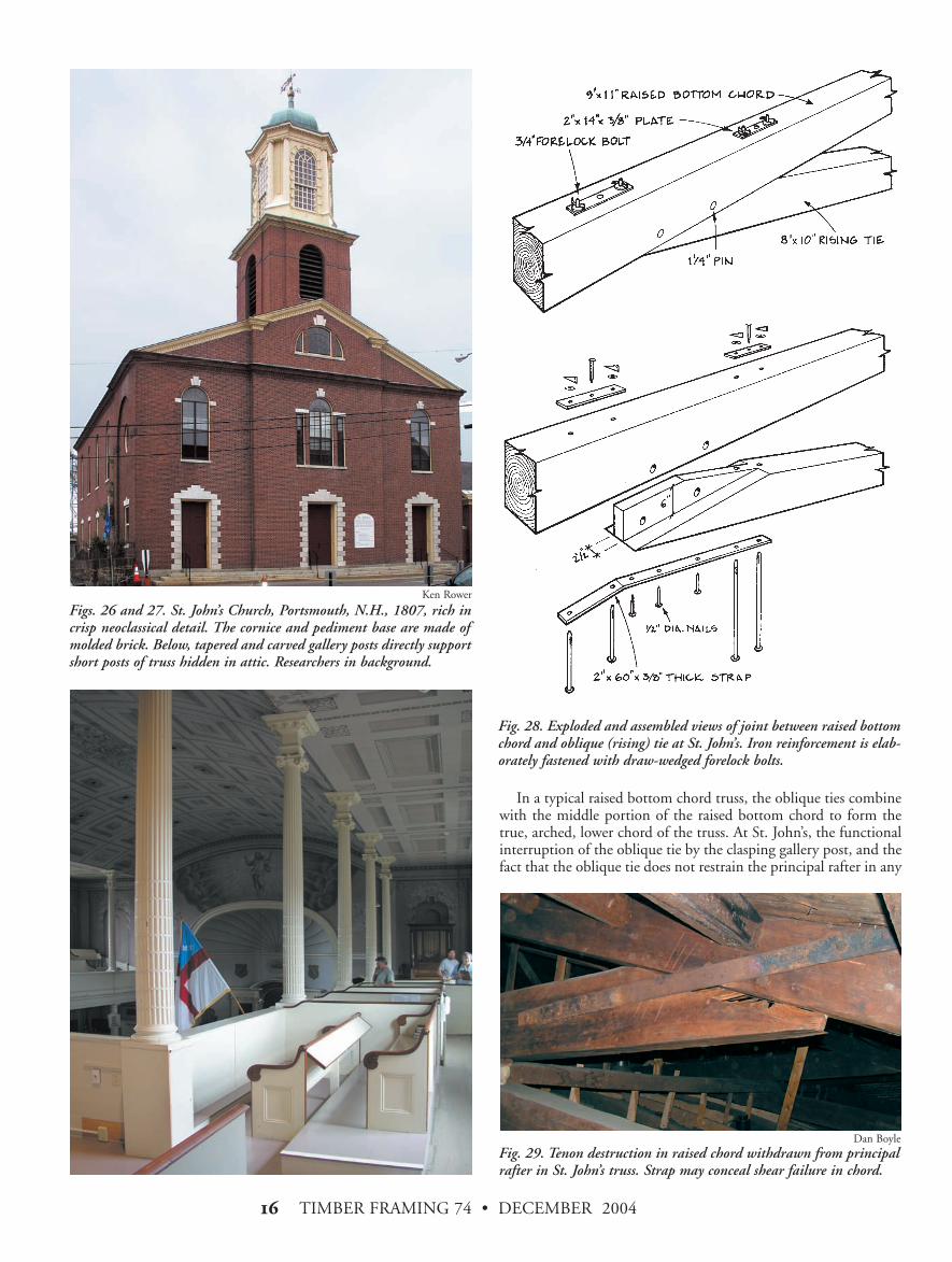
The problem at St. John’s is that the gallery post extensions propthe principal rafters near midspan but do not directly or evenclosely support the raised bottom chord and its joints with theprincipal rafter. Perhaps consequent from this anomaly are the onlyfailures we observed at St. John’s: two separated junctions betweenraised bottom chords and principal rafters, one noteworthy andone resulting in complete destruction of the chord tenon at thispinned and strapped joint (Fig. 29 overleaf ).
The unfortunate positioning of the gallery post-chord-rafterjunction may not have been the framer’s original intention. Anupside-down chalk drawing on the side of one of the oblique tiesprovides an elevation of the truss, obviously drawn before erectionand probably before assembly. In the drawing, the gallery postjoins the chord and rafter at a discrete node.
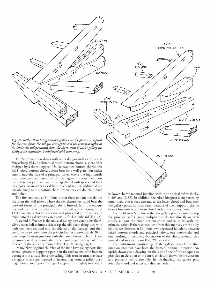
The St. John’s truss shares with other designs such as the one atShrewsbury, N.J., a substantial raised bottom chord, suspended atmidspan by a short kingpost. Unlike base-tied bottom chords, this9x11 raised bottom chord doesn’t bear on a wall plate, but rathertenons into the side of a principal rafter, where the high tensileloads developed are restrained by an elongated triple-pinned mor-tise and tenon joint and an iron strap affixed with spikes and fore-lock bolts. As in other raised bottom chord trusses, additional tiesrise obliquely to this bottom chord, where they are double-pinnedand bolted.
The first anomaly at St. John’s is that these oblique ties do notrise from the wall plates, where the ties themselves could bear theoutward thrust of the principal rafters. Instead, both the obliqueties and the principal rafters rise from gallery tie beams, stout11x12 members that lap over the wall plates and at the other endtenon into the gallery post extensions 12 ft. 4 in. inboard (Fig. 25).
A second difference is the unusual gallery post extensions them-selves, sawn half-columns that clasp the obliquely rising ties, withboth members reduced and shouldered at the passage, and thencontinue on to tenon into the principal rafter approximately 20 in.downslope from its junction with the raised bottom chord. Theseextensions sit directly over the turned and carved gallery columnsexposed in the audience room below (Fig. 24 facing page).
Many New England churches of the time have gallery posts thatextend upward to support a purlin in the roof system or to becomequeenposts in a truss above the ceiling. This truss in turn may havea kingpost truss superimposed on its straining beam, or gallery postsmight extend to support the upper kingpost truss slightly inboard of
Fig. 25. Rather than being joined together over the plate as is typicalfor the truss form, the oblique (rising) tie and the principal rafter atSt. John’s rise independently from the short, stout (11x12) gallery tie.Oblique tie connection is reinforced with iron strap.
TIMBER FRAMING 74 • DECEMBER 2004)%
In a typical raised bottom chord truss, the oblique ties combinewith the middle portion of the raised bottom chord to form thetrue, arched, lower chord of the truss. At St. John’s, the functionalinterruption of the oblique tie by the clasping gallery post, and thefact that the oblique tie does not restrain the principal rafter in any
Figs. 26 and 27. St. John’s Church, Portsmouth, N.H., 1807, rich incrisp neoclassical detail. The cornice and pediment base are made ofmolded brick. Below, tapered and carved gallery posts directly supportshort posts of truss hidden in attic. Researchers in background.
Fig. 28. Exploded and assembled views of joint between raised bottomchord and oblique (rising) tie at St. John’s. Iron reinforcement is elab-orately fastened with draw-wedged forelock bolts.
Ken Rower
Fig. 29. Tenon destruction in raised chord withdrawn from principalrafter in St. John’s truss. Strap may conceal shear failure in chord.
Dan Boyle

TIMBER FRAMING 74 • DECEMBER 2004 )&
compressed main brace. Without being able to attribute directinfluence on the design of St. John’s Portsmouth, we have fromsuch sources an idea of concepts current at the time in prestigiousand large-scale framing.
The kingposts and braces at St. John’s Portsmouth are oak, butthe remaining large and long timber is white pine. The oak pins are* and 1( inch according to use. The framing is scribe ruled and,most unusual, much of the joinery is centered rather than set clos-er to one face. The roof pitch is relatively low, approximately 5:12,and the five interior trusses are spaced typically 12 ft. 6 in. apart.The overall condition of the truss system is very good.
direct fashion, changes our view of its work. Inward of its jointwith the post, the oblique tie works as a brace (usually in com-pression but perhaps in tension under unbalanced roof loads)propping the raised bottom chord. Outward of the gallery post, theoblique tie works as a brace stiffening the post extension against theseveral forces it is opposing. A survey of Asher Benjamin andWilliam Pain imprints before 1806 shows the problem of aisledchurches with vaulted naves dealt with somewhat differently. Bothauthors illustrate the raised bottom chord truss in aisled buildings,but the oblique ties are omitted and replaced by steep braces risingfrom gallery post extension to bottom chord, or else the raised bot-tom chord itself is turned into a straining beam with the galleryextensions serving as queenposts (Benjamin 1797, pl. 27, 2; Pain1792, pl. 5, 7; Pain 1791, pl. 135 ).
Yeomans reproduces two drawings for roof trusses, in the 18th-century London church St. John’s of Smith Square, that bear inter-esting similarities to St. John’s of Portsmouth (Yeomans, 80). TheEnglish examples have flat-ceilinged aisles with vaulted naves andraised bottom chord kingpost trusses high in the ceiling. In onedrawing, braces rise from the aisle post extensions to strut the prin-cipal rafters several feet short of the raised chord-rafter junction. Inthe other drawing, an oblique tie rises from the short tie beam overthe aisle, as in Portsmouth, passes through or alongside a gallerypost extension, crosses the raised bottom chord and terminates atjoggles on the short kingpost, transforming itself from a tie into a
Fig. 30. Exploded and assembled views of side-strapped joint betweenprincipal rafter and raised bottom chord at St. John’s. Stout bolts inchord are not matched by spikes in rafter, perhaps because of mortise. Fig. 31. Exploded views of St. John’s kingpost head and foot joints.
TIMBER FRAMING 74 • DECEMBER 2004)'
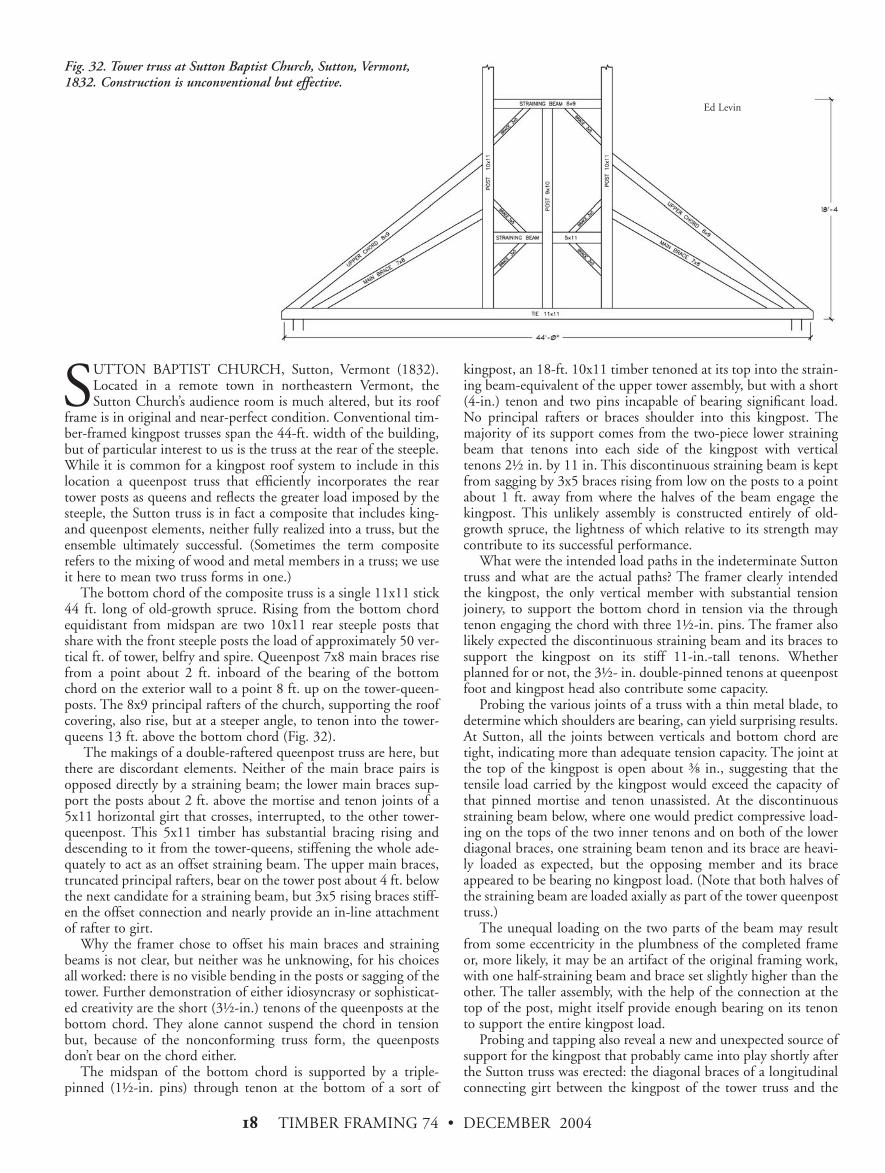
SUTTON BAPTIST CHURCH, Sutton, Vermont (1832).Located in a remote town in northeastern Vermont, theSutton Church’s audience room is much altered, but its roof
frame is in original and near-perfect condition. Conventional tim-ber-framed kingpost trusses span the 44-ft. width of the building,but of particular interest to us is the truss at the rear of the steeple.While it is common for a kingpost roof system to include in thislocation a queenpost truss that efficiently incorporates the reartower posts as queens and reflects the greater load imposed by thesteeple, the Sutton truss is in fact a composite that includes king-and queenpost elements, neither fully realized into a truss, but theensemble ultimately successful. (Sometimes the term compositerefers to the mixing of wood and metal members in a truss; we useit here to mean two truss forms in one.)
The bottom chord of the composite truss is a single 11x11 stick44 ft. long of old-growth spruce. Rising from the bottom chordequidistant from midspan are two 10x11 rear steeple posts thatshare with the front steeple posts the load of approximately 50 ver-tical ft. of tower, belfry and spire. Queenpost 7x8 main braces risefrom a point about 2 ft. inboard of the bearing of the bottomchord on the exterior wall to a point 8 ft. up on the tower-queen-posts. The 8x9 principal rafters of the church, supporting the roofcovering, also rise, but at a steeper angle, to tenon into the tower-queens 13 ft. above the bottom chord (Fig. 32).
The makings of a double-raftered queenpost truss are here, butthere are discordant elements. Neither of the main brace pairs isopposed directly by a straining beam; the lower main braces sup-port the posts about 2 ft. above the mortise and tenon joints of a5x11 horizontal girt that crosses, interrupted, to the other tower-queenpost. This 5x11 timber has substantial bracing rising anddescending to it from the tower-queens, stiffening the whole ade-quately to act as an offset straining beam. The upper main braces,truncated principal rafters, bear on the tower post about 4 ft. belowthe next candidate for a straining beam, but 3x5 rising braces stiff-en the offset connection and nearly provide an in-line attachmentof rafter to girt.
Why the framer chose to offset his main braces and strainingbeams is not clear, but neither was he unknowing, for his choicesall worked: there is no visible bending in the posts or sagging of thetower. Further demonstration of either idiosyncrasy or sophisticat-ed creativity are the short (3+-in.) tenons of the queenposts at thebottom chord. They alone cannot suspend the chord in tensionbut, because of the nonconforming truss form, the queenpostsdon’t bear on the chord either.
The midspan of the bottom chord is supported by a triple-pinned (1+-in. pins) through tenon at the bottom of a sort of
kingpost, an 18-ft. 10x11 timber tenoned at its top into the strain-ing beam-equivalent of the upper tower assembly, but with a short(4-in.) tenon and two pins incapable of bearing significant load.No principal rafters or braces shoulder into this kingpost. Themajority of its support comes from the two-piece lower strainingbeam that tenons into each side of the kingpost with verticaltenons 2+ in. by 11 in. This discontinuous straining beam is keptfrom sagging by 3x5 braces rising from low on the posts to a pointabout 1 ft. away from where the halves of the beam engage thekingpost. This unlikely assembly is constructed entirely of old-growth spruce, the lightness of which relative to its strength maycontribute to its successful performance.
What were the intended load paths in the indeterminate Suttontruss and what are the actual paths? The framer clearly intendedthe kingpost, the only vertical member with substantial tensionjoinery, to support the bottom chord in tension via the throughtenon engaging the chord with three 1+-in. pins. The framer alsolikely expected the discontinuous straining beam and its braces tosupport the kingpost on its stiff 11-in.-tall tenons. Whetherplanned for or not, the 3+- in. double-pinned tenons at queenpostfoot and kingpost head also contribute some capacity.
Probing the various joints of a truss with a thin metal blade, todetermine which shoulders are bearing, can yield surprising results.At Sutton, all the joints between verticals and bottom chord aretight, indicating more than adequate tension capacity. The joint atthe top of the kingpost is open about % in., suggesting that thetensile load carried by the kingpost would exceed the capacity ofthat pinned mortise and tenon unassisted. At the discontinuousstraining beam below, where one would predict compressive load-ing on the tops of the two inner tenons and on both of the lowerdiagonal braces, one straining beam tenon and its brace are heavi-ly loaded as expected, but the opposing member and its braceappeared to be bearing no kingpost load. (Note that both halves ofthe straining beam are loaded axially as part of the tower queenposttruss.)
The unequal loading on the two parts of the beam may resultfrom some eccentricity in the plumbness of the completed frameor, more likely, it may be an artifact of the original framing work,with one half-straining beam and brace set slightly higher than theother. The taller assembly, with the help of the connection at thetop of the post, might itself provide enough bearing on its tenonto support the entire kingpost load.
Probing and tapping also reveal a new and unexpected source ofsupport for the kingpost that probably came into play shortly afterthe Sutton truss was erected: the diagonal braces of a longitudinalconnecting girt between the kingpost of the tower truss and the
Fig. 32. Tower truss at Sutton Baptist Church, Sutton, Vermont,1832. Construction is unconventional but effective.
Ed Levin
TIMBER FRAMING 74 • DECEMBER 2004 )(
lower portion of the kingpost on the next interior truss. Themechanics are straightforward and arise from an endemic problemof a great many early New England churches. The front of Sutton’ssteeple, heavy, tall and exposed to wind loading, bears on a con-tinuously framed gable wall of the church, while the rear (the twoqueenposts and their superimposed load), rests on the first interiortruss, a clear-span the width of the church. No matter how power-ful the truss, some deflection will occur here from transverseshrinkage of vertical members, end-grain compression of mainbraces and even the small percentage of longitudinal shrinkage thatadds up significantly in very long main braces. Since the front ofthe steeple is fully supported to the ground and will not deflect, thesagging of the truss at the rear produces a rearward rotation of thesteeple, further increasing the load on the interior truss, finally pro-ducing that appearance of backward lean and even a slight kink inthe roof so often seen on early churches.
The tower truss kingpost at Sutton now bears back heavily onits longitudinal brace and connector, and the thrust is carriedthrough the connector and its lower diagonal brace to the foot ofthe next interior kingpost. The latter is through-tenoned to a tiebeam carrying joists and a finished ceiling and thus quite capableof resisting the partly horizontal thrust. The longitudinal bracesthat rise toward the tower truss kingpost are very heavily com-pressed on their bearing shoulders, whereas the braces rising awayare loose in their mortises. —JAN LEWANDOSKIJan Lewandoski of Restoration and Traditional Building in Stannard,Vt. ([email protected]), has examined hundreds of trusses and steeples.Co-investigators for the truss series Ed Levin, Ken Rower and JackSobon contributed research and advice for this article. Marcus Brandt,of Bethlehem, Pa., contributed significant research and support to theinvestigation of the Central Moravian Church in Bethlehem. JosephHammond provided help at Christ Episcopal Church in Shrewsbury,N.J., and Dan Boyle at St. John’s Church, Portsmouth, N.H.
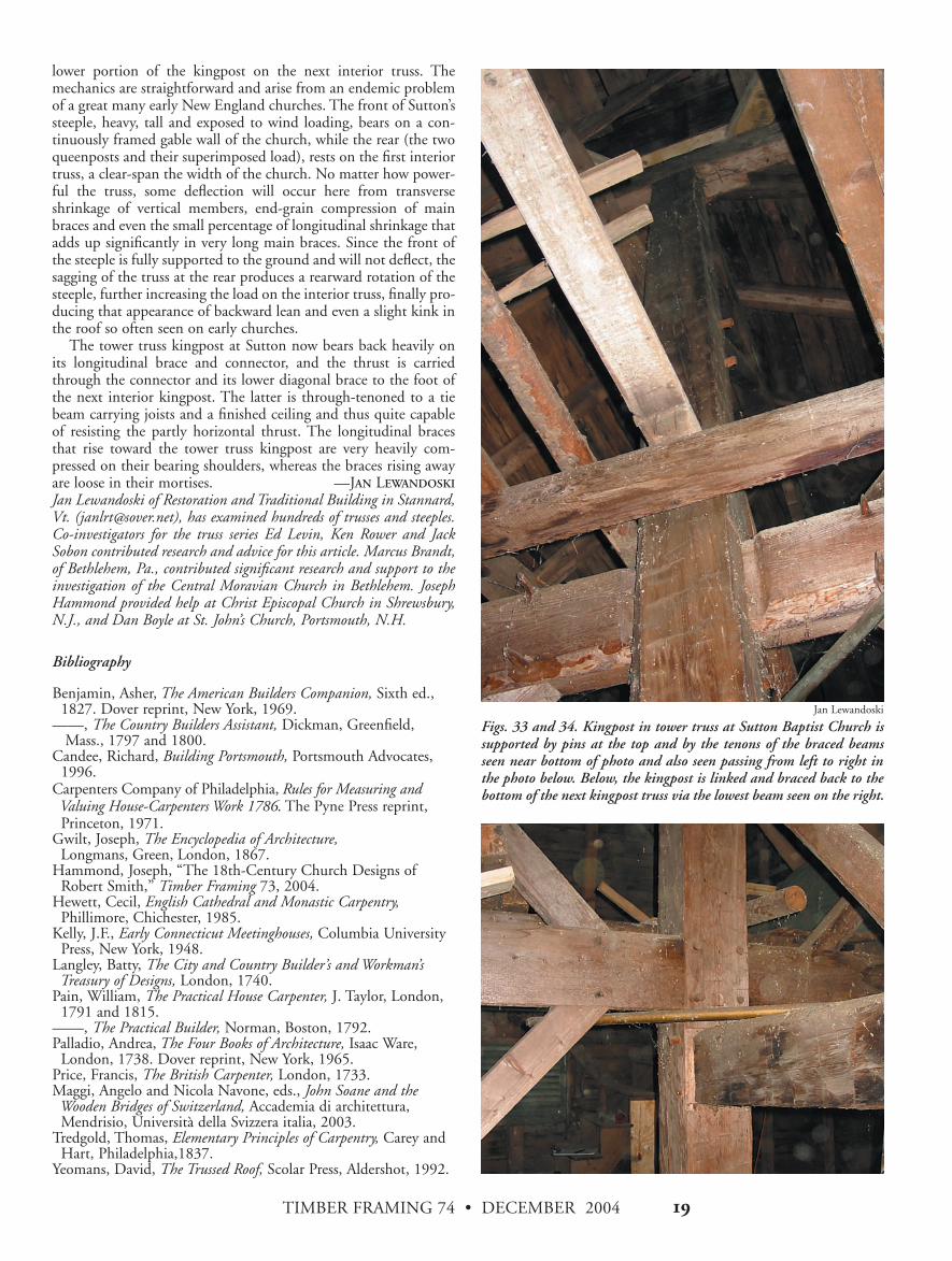
Figs. 33 and 34. Kingpost in tower truss at Sutton Baptist Church issupported by pins at the top and by the tenons of the braced beamsseen near bottom of photo and also seen passing from left to right inthe photo below. Below, the kingpost is linked and braced back to thebottom of the next kingpost truss via the lowest beam seen on the right.
Jan Lewandoski
Bibliography
Benjamin, Asher, The American Builders Companion, Sixth ed.,1827. Dover reprint, New York, 1969.
——, The Country Builders Assistant, Dickman, Greenfield, Mass., 1797 and 1800.
Candee, Richard, Building Portsmouth, Portsmouth Advocates,1996.
Carpenters Company of Philadelphia, Rules for Measuring andValuing House-Carpenters Work 1786. The Pyne Press reprint,Princeton, 1971.
Gwilt, Joseph, The Encyclopedia of Architecture,Longmans, Green, London, 1867.
Hammond, Joseph, “The 18th-Century Church Designs ofRobert Smith,” Timber Framing 73, 2004.
Hewett, Cecil, English Cathedral and Monastic Carpentry,Phillimore, Chichester, 1985.
Kelly, J.F., Early Connecticut Meetinghouses, Columbia UniversityPress, New York, 1948.
Langley, Batty, The City and Country Builder’s and Workman’sTreasury of Designs, London, 1740.
Pain, William, The Practical House Carpenter, J. Taylor, London,1791 and 1815.
——, The Practical Builder, Norman, Boston, 1792.Palladio, Andrea, The Four Books of Architecture, Isaac Ware,
London, 1738. Dover reprint, New York, 1965. Price, Francis, The British Carpenter, London, 1733.Maggi, Angelo and Nicola Navone, eds., John Soane and theWooden Bridges of Switzerland, Accademia di architettura,Mendrisio, Università della Svizzera italia, 2003.
Tredgold, Thomas, Elementary Principles of Carpentry, Carey andHart, Philadelphia,1837.
Yeomans, David, The Trussed Roof, Scolar Press, Aldershot, 1992.
TIMBER FRAMING 74 • DECEMBER 2004!*
From the beginning of this series, roof live load applied to all trussframe models has been based on 65 psf ground snow load. This figuremade sense in interior northern New England but, in the cases ofPortsmouth, N.H., and especially Bethlehem, Pa., and Shrewsbury,N.J., it represents an unrealistically high load. Therefore I havereduced roof live load at Portsmouth to 75 percent of the prior stan-dard and, on the Pennsylvania and New Jersey trusses, to half.—EL
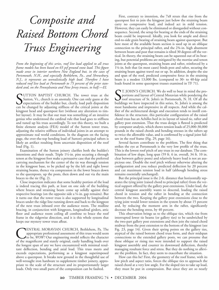
SUTTON BAPTIST CHURCH. The tower truss at theSutton, Vt., church is an anomaly. One can only guess at theexpectations of the builder but, clearly, load path disposition
can be changed by adjusting stiffness of the critical joints at thekingpost head and queenpost feet (without any alteration to tim-ber layout). It may be that our man was something of an intuitivegenius who understood the cardinal rule that load goes to stiffnessand tuned up his truss accordingly. To test this theory, we built afinite element analysis (FEA) model of the Sutton tower truss,adjusting the relative stiffness of individual joints in an attempt toapproximate real world conditions. In the diagram on the facingpage, the over-the-top bending load of Sutton’s principal rafters islikely an artifact resulting from uncertain disposition of the roofload (Fig. 1).
Examination of the Sutton joinery clarifies both the builder’sintentions and their result. Triple 1+-in. pins securing a throughtenon at the kingpost foot make a persuasive case that the preferredcarrying mechanism for the center of the tie was through tensionin the kingpost base, to be picked up by the left and right lowerstraining beams, thence via compression in the lower braces downto the queenposts, up the posts, then down and out via the mainbraces to the tie (Fig. 2).
Close inspection indicates that some healthy portion of the loadis indeed tracing this path, at least on one side of the buildingwhere braces and straining beam come up solidly against theirrespective bearings (on the opposite side a (-in. gap remains). Butit turns out that the tower truss is also supported by longitudinalbraces under the ridge line running down and back to the kingpostof the next truss inboard over the audience room. The midlinebracing, in conjunction with kingposts, longitudinal girders, atticfloor and audience room ceiling all combine to brace the roofframe in the ridgewise direction, and it is this whole system thatkeeps our mystery tower truss afloat.
CENTRAL MORAVIAN CHURCH, Bethlehem, Pa. Theappropriate professional assessment of this truss would seemto be, WOW! Our engineering model reflects the character
of the magnificent and stately original, easily handling loads overthe longest span of any we have encountered with minimal resul-tant deflection, bending and axial load. This truss meets andexceeds expectations, performing as a kingpost superimposedabove a queenpost. It breaks new ground in the thoughtful use ofwell-wrought iron hardware to supplement timber joinery, appro-priate to the scale of the structure and its proportionately largerloads. Only two small parts of the composition can be faulted.
First, contrary to intention, the 7x8 struts that rise from thequeenpost feet to join the kingpost just below the straining beamcarry no compressive load, and indeed act in mild tension.However, they can easily be eliminated or disregarded without con-sequence. Second, the setup for bearing at the ends of the strainingbeam could be improved. Ideally, you look for ample and directend-to-side grain bearing of straining beam against queenpost. Buthere most of the available beam section is used up in an obliqueconnection to the principal rafter, and the 2'-in. high abutmentbetween beam and post that remains is tilted 30 degrees off the ver-tical. In theory, the straining beam can be squeezed out of its bear-ing, but potential problems are mitigated by the mortise and tenonjoints at the queenpost, straining beam and rafter, reinforced by a1(-in. bolt that (in most cases) binds post and rafter, securing thestraining beam against travel out or up. In addition, despite the sizeand span of the roof, predicted compressive force in the strainingbeam is a modest 13,000 lbs. (compared to 30- to 40-kip axialloads found in some queenpost trusses examined in TF 71).
ST. JOHN’S CHURCH. We do well to bear in mind the pro-portions and layout of Central Moravian while pondering theroof structure of St. John’s in Portsmouth, N. H. Of all the
buildings we have inspected in this series, St. John’s is among themost handsome and impressive in all respects. And while the cal-iber of the architectural design and execution tends to instill con-fidence in the structure, this particular configuration of the raisedchord truss has an Achilles heel in its layout of raised tie, rafter andgallery post extension. That the truss design is flawed is predictedby computer analysis, which shows tension loads of 25,000-30,000pounds in the raised chords and bending stresses in the rafters upto twice the allowable value, and is confirmed by a signal joint fail-ure in the roof frame (Fig. 29, page 16).
Several factors contribute to the problem. The first thing thatstrikes the eye at Portsmouth is the very low profile of the truss.This is the lowest roof pitch of any truss in our database. The com-bination of low slope, long span (59 ft. 6 in. overall, 34 ft. 10 in.clear between gallery posts) and relatively heavy load is not an aus-picious one. Double the roof pitch without otherwise altering theconfiguration and you reduce predicted deflection by 20 percentand cut maximum tension load in half (although bending stressremains essentially unchanged).
But the principal issue is the 2-ft. distance that horizontally sep-arates the tying joint (raised chord to principal rafter) from the ver-tical support offered by the gallery post extensions. Under load, thecentral kingpost assembly wants to descend, loading the raisedchord in tension and the rafter in bending at the connectionbetween the two. Keeping the gallery post extensions close to thetying joint would lower tension in the system by about 15 percentand, by reducing the moment arm in the rafter, significantlydecrease the bending stress, by 40 percent.
This observation brings us to the oblique ties, which rise frominterrupted lower tie beams (or gallery ties) to be sandwiched bythe two-part gallery post extensions and then join the raised chordmidway from the post extension to the bottom of the kingpost (seeFig. 23, page 14). Given their spring points on the gallery ties,atypical of the raised bottom chord truss form, and their midspanconnections to the extended gallery posts, we can presume thatthese oblique or rising ties were intended to support the raisedkingpost assembly and counter its downward deflection, therebymanaging resultant force and stress. But they do nothing to allevi-ate the problem. In fact, they seem to exacerbate the situation.
How can this be? First, the geometry of the roof frame, with itslow pitch and aspect ratio, forces the oblique ties to approach theraised chord at a very low angle. For the sloped ties to take up load,they must be put in compression. But since they are so nearly
Composite andRaised Bottom Chord
Truss Engineering
TIMBER FRAMING 74 • DECEMBER 2004 !)
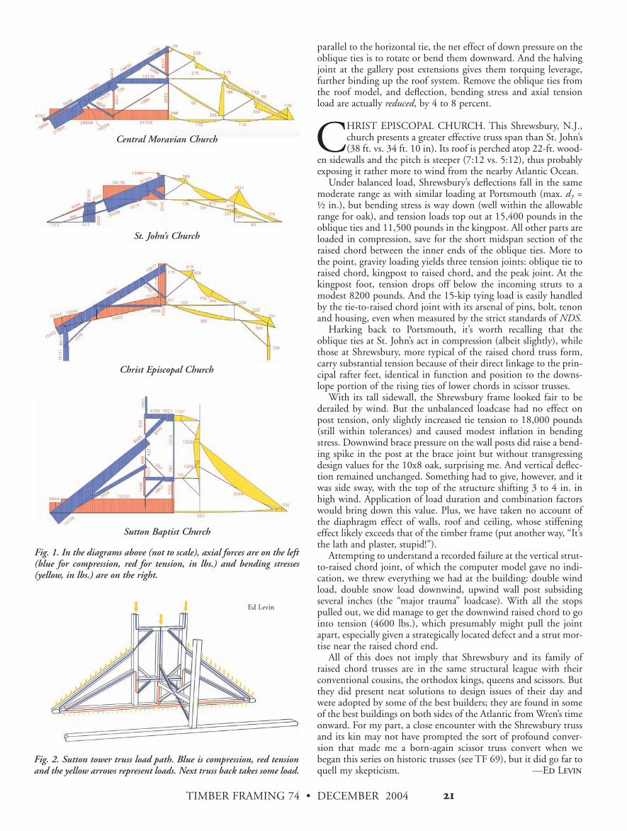
Fig. 1. In the diagrams above (not to scale), axial forces are on the left(blue for compression, red for tension, in lbs.) and bending stresses(yellow, in lbs.) are on the right.
Central Moravian Church
St. John’s Church
Christ Episcopal Church
Sutton Baptist Church
Fig. 2. Sutton tower truss load path. Blue is compression, red tensionand the yellow arrows represent loads. Next truss back takes some load.
parallel to the horizontal tie, the net effect of down pressure on theoblique ties is to rotate or bend them downward. And the halvingjoint at the gallery post extensions gives them torquing leverage,further binding up the roof system. Remove the oblique ties fromthe roof model, and deflection, bending stress and axial tensionload are actually reduced, by 4 to 8 percent.
CHRIST EPISCOPAL CHURCH. This Shrewsbury, N.J.,church presents a greater effective truss span than St. John’s(38 ft. vs. 34 ft. 10 in). Its roof is perched atop 22-ft. wood-
en sidewalls and the pitch is steeper (7:12 vs. 5:12), thus probablyexposing it rather more to wind from the nearby Atlantic Ocean.
Under balanced load, Shrewsbury’s deflections fall in the samemoderate range as with similar loading at Portsmouth (max. dy =+ in.), but bending stress is way down (well within the allowablerange for oak), and tension loads top out at 15,400 pounds in theoblique ties and 11,500 pounds in the kingpost. All other parts areloaded in compression, save for the short midspan section of theraised chord between the inner ends of the oblique ties. More tothe point, gravity loading yields three tension joints: oblique tie toraised chord, kingpost to raised chord, and the peak joint. At thekingpost foot, tension drops off below the incoming struts to amodest 8200 pounds. And the 15-kip tying load is easily handledby the tie-to-raised chord joint with its arsenal of pins, bolt, tenonand housing, even when measured by the strict standards of NDS.
Harking back to Portsmouth, it’s worth recalling that theoblique ties at St. John’s act in compression (albeit slightly), whilethose at Shrewsbury, more typical of the raised chord truss form,carry substantial tension because of their direct linkage to the prin-cipal rafter feet, identical in function and position to the downs-lope portion of the rising ties of lower chords in scissor trusses.
With its tall sidewall, the Shrewsbury frame looked fair to bederailed by wind. But the unbalanced loadcase had no effect onpost tension, only slightly increased tie tension to 18,000 pounds(still within tolerances) and caused modest inflation in bendingstress. Downwind brace pressure on the wall posts did raise a bend-ing spike in the post at the brace joint but without transgressingdesign values for the 10x8 oak, surprising me. And vertical deflec-tion remained unchanged. Something had to give, however, and itwas side sway, with the top of the structure shifting 3 to 4 in. inhigh wind. Application of load duration and combination factorswould bring down this value. Plus, we have taken no account ofthe diaphragm effect of walls, roof and ceiling, whose stiffeningeffect likely exceeds that of the timber frame (put another way, “It’sthe lath and plaster, stupid!”).
Attempting to understand a recorded failure at the vertical strut-to-raised chord joint, of which the computer model gave no indi-cation, we threw everything we had at the building: double windload, double snow load downwind, upwind wall post subsidingseveral inches (the “major trauma” loadcase). With all the stopspulled out, we did manage to get the downwind raised chord to gointo tension (4600 lbs.), which presumably might pull the jointapart, especially given a strategically located defect and a strut mor-tise near the raised chord end.
All of this does not imply that Shrewsbury and its family ofraised chord trusses are in the same structural league with theirconventional cousins, the orthodox kings, queens and scissors. Butthey did present neat solutions to design issues of their day andwere adopted by some of the best builders; they are found in someof the best buildings on both sides of the Atlantic from Wren’s timeonward. For my part, a close encounter with the Shrewsbury trussand its kin may not have prompted the sort of profound conver-sion that made me a born-again scissor truss convert when webegan this series on historic trusses (see TF 69), but it did go far toquell my skepticism. —ED LEVIN
Ed Levin