Embed Size (px)
Citation preview
ETSI TS 102 636-6-1 V1.1.1 (2011-03)
Technical Specification
Intelligent Transport Systems (ITS);Vehicular Communications;
GeoNetworking;Part 6: Internet Integration;
Sub-part 1: Transmission of IPv6 Packets overGeoNetworking Protocols
ETSI
ETSI TS 102 636-6-1 V1.1.1 (2011-03) 2
Reference DTS/ITS-0030005
Keywords ITS, IPv6, addressing, network,
point-to-multipoint, point-to-point, protocol
ETSI
650 Route des Lucioles F-06921 Sophia Antipolis Cedex - FRANCE
Tel.: +33 4 92 94 42 00 Fax: +33 4 93 65 47 16
Siret N° 348 623 562 00017 - NAF 742 C
Association à but non lucratif enregistrée à la Sous-Préfecture de Grasse (06) N° 7803/88
Important notice
Individual copies of the present document can be downloaded from: http://www.etsi.org
The present document may be made available in more than one electronic version or in print. In any case of existing or perceived difference in contents between such versions, the reference version is the Portable Document Format (PDF).
In case of dispute, the reference shall be the printing on ETSI printers of the PDF version kept on a specific network drive within ETSI Secretariat.
Users of the present document should be aware that the document may be subject to revision or change of status. Information on the current status of this and other ETSI documents is available at
http://portal.etsi.org/tb/status/status.asp
If you find errors in the present document, please send your comment to one of the following services: http://portal.etsi.org/chaircor/ETSI_support.asp
Copyright Notification
No part may be reproduced except as authorized by written permission. The copyright and the foregoing restriction extend to reproduction in all media.
© European Telecommunications Standards Institute 2011.
All rights reserved.
DECTTM, PLUGTESTSTM, UMTSTM, TIPHONTM, the TIPHON logo and the ETSI logo are Trade Marks of ETSI registered for the benefit of its Members.
3GPPTM is a Trade Mark of ETSI registered for the benefit of its Members and of the 3GPP Organizational Partners. LTE™ is a Trade Mark of ETSI currently being registered
for the benefit of its Members and of the 3GPP Organizational Partners. GSM® and the GSM logo are Trade Marks registered and owned by the GSM Association.
ETSI
ETSI TS 102 636-6-1 V1.1.1 (2011-03) 3
Contents
Intellectual Property Rights ................................................................................................................................ 6
Foreword ............................................................................................................................................................. 6
Introduction ........................................................................................................................................................ 6
1 Scope ........................................................................................................................................................ 8
2 References ................................................................................................................................................ 9
2.1 Normative references ......................................................................................................................................... 9
2.2 Informative references ...................................................................................................................................... 10
3 Definitions, symbols and abbreviations ................................................................................................. 12
3.1 Definitions ........................................................................................................................................................ 12
3.2 Symbols ............................................................................................................................................................ 12
3.3 Abbreviations ................................................................................................................................................... 12
4 GN6ASL in the ITS station architecture ................................................................................................ 13
5 IPv6 link models and interfaces ............................................................................................................. 14
5.1 Rationales ......................................................................................................................................................... 14
5.2 Required properties of supported IPv6 link models ......................................................................................... 15
5.2.1 Number and types of virtual link ................................................................................................................ 15
5.2.2 Geographical virtual links ........................................................................................................................... 15
5.2.3 Topological virtual links ............................................................................................................................. 15
5.3 Recommended properties of virtual interfaces ................................................................................................. 15
5.3.1 Number and types of virtual interfaces ....................................................................................................... 15
5.3.2 Usage of specific virtual interfaces ............................................................................................................. 16
5.3.2.1 Ethernet V2.0/IEEE 802.3 LAN virtual interfaces ................................................................................ 16
5.3.2.2 NBMA virtual interfaces ....................................................................................................................... 16
5.3.2.3 Point-to-point virtual interfaces ............................................................................................................ 16
6 Bridging support ..................................................................................................................................... 17
6.1 Rationales ......................................................................................................................................................... 17
6.2 Required properties .......................................................................................................................................... 18
6.3 Media-dependent implementations .................................................................................................................. 18
6.3.1 IEEE 802 integration service ...................................................................................................................... 18
7 IPv6/GeoNetworking interface service specification ............................................................................. 19
8 Encapsulation characteristics ................................................................................................................. 19
8.1 Maximum transmission unit ............................................................................................................................. 19
8.2 Packet delivery ................................................................................................................................................. 19
8.2.1 Outbound traffic .......................................................................................................................................... 19
8.2.2 Inbound traffic ............................................................................................................................................ 21
8.3 Frame format .................................................................................................................................................... 22
9 IPv6 multicast and anycast support ........................................................................................................ 23
9.1 Overview .......................................................................................................................................................... 23
9.2 Legacy IPv6 multicast support ......................................................................................................................... 23
9.2.1 IPv6 link-local multicast ............................................................................................................................. 23
9.2.2 IPv6 wider-scope multicast ......................................................................................................................... 24
9.2.3 Geocasting of legacy IPv6 multicast traffic ................................................................................................ 24
9.3 Legacy IPv6 anycast support ............................................................................................................................ 24
10 IPv6 neighbor discovery support ............................................................................................................ 24
10.1 On-link determination ...................................................................................................................................... 24
10.2 Address configuration ...................................................................................................................................... 25
10.2.1 Stateless address autoconfiguration ............................................................................................................ 25
10.2.2 Stateful address configuration..................................................................................................................... 25
10.2.3 Manual address configuration ..................................................................................................................... 26
10.3 Address resolution ............................................................................................................................................ 26
ETSI
ETSI TS 102 636-6-1 V1.1.1 (2011-03) 4
10.3.1 Non-ND-based address resolution .............................................................................................................. 26
10.3.2 ND-based address resolution ...................................................................................................................... 26
10.4 Neighbor unreachability detection ................................................................................................................... 27
10.5 Protocol constants............................................................................................................................................. 27
11 Support for pseudonym change .............................................................................................................. 27
11.1 Rationales ......................................................................................................................................................... 27
11.2 Required operations .......................................................................................................................................... 28
Annex A (normative): ASN.1 encoding of the GN6ASL MIB .......................................................... 29
A.1 Modules .................................................................................................................................................. 29
A.1.1 ITSGN6ASL-MIB ............................................................................................................................................ 29
Annex B (normative): MIB attributes ................................................................................................ 32
B.1 ITSGN6ASL-MIB attributes values ....................................................................................................... 32
Annex C (informative): IPv6/GeoNetworking data SAP .................................................................... 33
C.1 Basic data SAP (GN6_SAP) .................................................................................................................. 33
C.1.1 Overview .......................................................................................................................................................... 33
C.1.2 Service primitives ............................................................................................................................................. 33
C.1.2.1 GN6-UNITDATA.request .......................................................................................................................... 33
C.1.2.1.1 Semantics .............................................................................................................................................. 33
C.1.2.1.2 When generated ..................................................................................................................................... 33
C.1.2.1.3 Effect on receipt .................................................................................................................................... 33
C.1.2.2 GN6-UNITDATA.indication ...................................................................................................................... 34
C.1.2.2.1 Semantics .............................................................................................................................................. 34
C.1.2.2.2 When generated ..................................................................................................................................... 34
C.1.2.2.3 Effect on receipt .................................................................................................................................... 34
C.2 Experimental extended data SAP (EGN6_SAP) .................................................................................... 34
C.2.1 Overview .......................................................................................................................................................... 34
C.2.2 Service primitives ............................................................................................................................................. 35
C.2.2.1 EGN6-UNITDATA.request ........................................................................................................................ 35
C.2.2.1.1 Semantics .............................................................................................................................................. 35
C.2.2.1.2 When generated ..................................................................................................................................... 35
C.2.2.1.3 Effect on receipt .................................................................................................................................... 35
C.2.2.2 EGN6-UNITDATA.indication ................................................................................................................... 35
C.2.2.2.1 Semantics .............................................................................................................................................. 35
C.2.2.2.2 When generated ..................................................................................................................................... 36
C.2.2.2.3 Effect on receipt .................................................................................................................................... 36
Annex D (informative): Geographic IPv6 multicast support (experimental) ................................... 37
D.1 Overview ................................................................................................................................................ 37
D.2 Pre-defined geographical IPv6 multicast groups .................................................................................... 37
D.3 Other studied mechanisms...................................................................................................................... 37
Annex E (informative): Exemplary implementations ......................................................................... 39
E.1 Virtual links and interfaces ..................................................................................................................... 39
E.2 Packet delivery with Ethernet V2.0/IEEE 802.3 LAN virtual interfaces ............................................... 39
E.2.1 Outbound traffic ............................................................................................................................................... 39
E.2.2 Inbound traffic .................................................................................................................................................. 40
E.3 Bridging support ..................................................................................................................................... 40
E.4 GeoNet project implementations results ................................................................................................ 41
Annex F (informative): Support for Network Mobility Basic Support ............................................. 42
F.1 Purpose of this annex ............................................................................................................................. 42

ETSI
ETSI TS 102 636-6-1 V1.1.1 (2011-03) 5
F.2 Mode of operation via GN6ASL ............................................................................................................ 42
F.3 Sub-optimal routing issues ..................................................................................................................... 42
Annex G (informative): Security and privacy considerations ............................................................ 43
G.1 Purpose of this annex ............................................................................................................................. 43
G.2 Recommendations for security mechanisms .......................................................................................... 43
G.3 Recommendations for privacy-protecting deployment .......................................................................... 43
Annex H (informative): Bibliography ................................................................................................... 44
History .............................................................................................................................................................. 45

ETSI
ETSI TS 102 636-6-1 V1.1.1 (2011-03) 6
Intellectual Property Rights IPRs essential or potentially essential to the present document may have been declared to ETSI. The information pertaining to these essential IPRs, if any, is publicly available for ETSI members and non-members, and can be found in ETSI SR 000 314: "Intellectual Property Rights (IPRs); Essential, or potentially Essential, IPRs notified to ETSI in respect of ETSI standards", which is available from the ETSI Secretariat. Latest updates are available on the ETSI Web server (http://webapp.etsi.org/IPR/home.asp).
Pursuant to the ETSI IPR Policy, no investigation, including IPR searches, has been carried out by ETSI. No guarantee can be given as to the existence of other IPRs not referenced in ETSI SR 000 314 (or the updates on the ETSI Web server) which are, or may be, or may become, essential to the present document.
Foreword This Technical Specification (TS) has been produced by ETSI Technical Committee Intelligent Transport System (ITS).
The present document is part 6, sub-part 1 of a multi-part deliverable covering GeoNetworking and Transport, as identified below:
Part 1: "Requirements for GeoNetworking and Data Transport Protocol ";
Part 2: "Scenarios for GeoNetworking";
Part 3: "Network architecture";
Part 4: "Geographical addressing and forwarding for point-to-point and point-to-multipoint communications;
Part 5: "Transport protocols";
Part 6: "Internet integration";
Sub-part 1: "Transmission of IPv6 Packets over GeoNetworking Protocols";
Part 7: "Network management";
Introduction The ETSI GeoNetworking protocol [i.25] and [i.26] is a non-IP network-layer protocol that provides geographic addressing and forwarding. Applications and facilities specifically designed for GeoNetworking exploit these functionalities, for example to disseminate warning or generic information messages to geographically scoped areas. This approach satisfies the requirements of several ITS services, whose application domain is limited to networks that are disconnected from large existing network infrastructures. However, several ITS applications require the integration of ITS stations with larger networks like private transport networks or the Internet.
In order to connect networks based on GeoNetworking to networks running the Internet Protocol (IP), which represent the majority of currently deployed large networks, it is necessary to allow GeoNetworking stations to act like Internet hosts or routers. ETSI Technical Committee ITS recognizes IP version 6 (IPv6,[7]) as the primary and only version of IP to be necessarily supported by ITS stations.
The present document introduces a set of mechanisms that allow GeoNetworking to transport IPv6 packets without introducing modifications to existing IPv6 protocol implementations. By deploying these mechanisms, the following two main advantages are achieved:
1) coverage offered by point-of-attachment to the Internet like road-side ITS stations is extended by means of sub-IP geographic routing; and
2) IPv6 multicast traffic can be geocasted, i.e. addressed and delivered to all ITS stations currently located within a geographic area.

ETSI
ETSI TS 102 636-6-1 V1.1.1 (2011-03) 7
The present document includes a data SAP that enables an IPv6 protocol entity to send and receive packets over GeoNetworking. This SAP is defined in annex C. The present document does not include a management SAP towards the ITS station management entity.
NOTE: In the reminder of the present document, when the sole term "GeoNetworking" is used, it is to be intended as the ETSI GeoNetworking protocol consisting of the combination of the media-independent part [i.25] and at least one of the media-dependent parts (such as [i.26]). It should be noted that the media-dependent extensions do not represent distinct protocol layers.
ETSI
ETSI TS 102 636-6-1 V1.1.1 (2011-03) 8
1 Scope The present document specifies the transmission of IPv6 packets over the ETSI GeoNetworking protocol [i.25] via a protocol adaptation sub-layer referred to as the GN6ASL (GeoNetworking to IPv6 Adaptation Sub-Layer). The scope of the present document is limited to the GN6ASL.
The techniques specified in the present document fulfil the requirements for GeoNetworking and IPv6 integration described in [3], clause 5.9. In particular, these techniques allow for the transport of IPv6 packets by ETSI GeoNetworking protocol [i.25], enabling sub-IP multi-hop delivery of IPv6 packets, e.g. in a vehicular network. As a result, the connectivity provided by point-of-attachments to IPv6 infrastructure networks is extended by means of mobile relay nodes. In addition to that, the techniques described in the present document allow for geocasting of IPv6 multicast packets.
The scope of the GN6ASL is limited to the fulfilment of the requirements for GeoNetworking and IPv6 integration described in [3], clause 5.9, by enabling an ITS station including a Geoadhoc router [5] running GeoNetworking and an IPv6-compliant protocol layer to:
1) exchange IPv6 packets with other ITS stations using link-local IPv6 addresses;
2) acquire globally routable IPv6 unicast addresses and communicate with an arbitrary IPv6 host located in the Internet, whenever an ITS station including a Geoadhoc router and including or connected to an access router [5] providing IPv6 connectivity to the Internet is reachable directly or via other relay ITS stations;
3) to perform the operations required by [20] for a Mobile Router whenever i) an ITS mobile router supporting Network Mobility Basic Support (NEMO BS) [20] is present in the ITS station and runs on top of the GN6ASL and ii) an ITS station including a Geoadhoc router and including or connected to an access router [5] providing IPv6 connectivity to the Internet is reachable directly or via other relay ITS stations.
NOTE: The present document adopts the definition of "IPv6-compliant" and "sub-IP multi-hop delivery" introduced in clause 3.1.
Extending the IPv6 basic standards [7], [8], [9], [10] and [12] to support new features is outside the scope of the present document. Extensions to NEMO BS [15] are outside the scope of the present document. Mechanisms for the dissemination of IPv6 routing information for hosts and routers not directly attaching to the network where GeoNetworking is used are outside the scope of the present document (e.g. discovery of IPv6 in-vehicle prefixes). However, the present document aims at providing the underlying support for the dissemination of such routing information, i.e. IPv6 multicast support for the network where the GeoNetworking protocol is used.
With respect to IPv6 multicast and anycast support, the present document is limited to the support required to enable distribution of IPv6 multicast and anycast traffic on a shared link. Amendments to specific IPv6 multicast forwarding mechanisms are out of the scope of the present document. However, the present document aims at not preventing existing IPv6 multicast forwarding mechanisms from being used in conjunction with the GN6ASL.
In order to facilitate the deployment of ITS systems, the present document aims at maintaining backward compatibility with pre-existent IPv6-compliant protocol implementations and NEMO BS implementations compliant with [15]. An exemplary usage of NEMO BS with the GN6ASL is overviewed in the informative annex F.
The present document does not request any assignment or reservation of IPv6 prefixes or suffixes for specific purposes.
The mechanisms specified in the present document are distinct from but compatible with the IPv6-related functionalities in [i.24], which specifies how IPv6 networking is generally operated in ITS stations. The techniques described in the present document provide a way to transport IPv6 packets that is fully compatible with the IPv6 specifications and pre-existing implementations, and hence is compatible with [i.19].
ETSI
ETSI TS 102 636-6-1 V1.1.1 (2011-03) 9
2 References References are either specific (identified by date of publication and/or edition number or version number) or non-specific. For specific references, only the cited version applies. For non-specific references, the latest version of the reference document (including any amendments) applies.
Referenced documents which are not found to be publicly available in the expected location might be found at http://docbo0x.etsi.org/Reference.
NOTE: While any hyperlinks included in this clause were valid at the time of publication ETSI cannot guarantee their long term validity.
2.1 Normative references The following referenced documents are necessary for the application of the present document.
[1] ETSI EN 302 665: "Intelligent Transport Systems (ITS); Communications Architecture".
[2] ETSI ES 202 663: "Intelligent Transport Systems (ITS); European profile standard for the physical and medium access control layer of Intelligent Transport Systems operating in the 5 GHz frequency band".
[3] ETSI TS 102 636-1: "Intelligent Transport Systems (ITS); Vehicular Communications; GeoNetworking; Part 1: Requirements".
[4] ETSI TS 102 636-2: "Intelligent Transport Systems (ITS); Vehicular Communications; GeoNetworking; Part 2: Scenarios".
[5] ETSI TS 102 636-3: "Intelligent Transport Systems (ITS); Vehicular Communications; GeoNetworking; Part 3: Network architecture".
[6] ETSI EN 302 931: "Intelligent Transport Systems (ITS); Vehicular Communications; Geographical Area Definition".
[7] IETF RFC 2460: "Internet Protocol, Version 6 (IPv6) Specification".
[8] IETF RFC 4291: "IP Version 6 (IPv6) Addressing Architecture".
[9] IETF RFC 4007: "IPv6 Scoped Address Architecture".
[10] IETF RFC 4861: "Neighbor Discovery for IP version 6 (IPv6)".
[11] IETF RFC 5942: "IPv6 Subnet Model: The Relationship between Links and Subnet Prefixes".
[12] IETF RFC 4862: "IPv6 Stateless Address Autoconfiguration".
[13] IETF RFC 3753: "Mobility Related Terminology".
[14] IETF RFC 4885: "Network Mobility Support Terminology".
[15] IETF RFC 3963: "Network Mobility (NEMO) Basic Support Protocol".
[16] IETF RFC 3484: "Default Address Selection for Internet Protocol version 6 (IPv6)".
[17] IETF RFC 2464: "Transmission of IPv6 Packets over Ethernet Networks".
[18] IETF RFC 2491: "IPv6 over Non-Broadcast Multiple Access (NBMA) networks".
[19] IETF RFC 2472: "IP Version 6 over PPP".
[20] IETF RFC 3810: "Multicast Listener Discovery Version 2 (MLDv2) for IPv6".
[21] IETF RFC 4601: "Protocol Independent Multicast - Sparse Mode (PIM-SM): Protocol Specification (Revised)".

ETSI
ETSI TS 102 636-6-1 V1.1.1 (2011-03) 10
[22] IETF RFC 4605: "Internet Group Management Protocol (IGMP) / Multicast Listener Discovery (MLD)-Based Multicast Forwarding ("IGMP/MLD Proxying")".
[23] IETF RFC 3306: "Unicast-Prefix-based IPv6 Multicast Addresses".
[24] IETF RFC 2022: "Support for Multicast over UNI 3.0/3.1 based ATM Networks".
[25] IETF RFC 1042: "A Standard for the Transmission of IP Datagrams over IEEE 802 Networks".
[26] IETF RFC 3971: "SEcure Neighbor Discovery (SEND)".
[27] IETF RFC 4293: "Management Information Base for the Internet Protocol (IP)".
[28] ISO/IEC 8802-2:1998: "Information technology-Telecommunications and information exchange between systems-Local and metropolitan area networks-Specific requirements-Part 2: Logical link control".
[29] ISO/IEC 15802-3: "Information Technology-Telecommunications and information exchange between systems-Local and metropolitan area networks-Common specifications-Part 3: Media Access Control (MAC) Bridges" (previously known as IEEE Std 802.1D-1998).
[30] IEEE 802.11:2007: "IEEE Standard for Information Technology - Telecommunications and Information Exchange Between Systems-Local and Metropolitan Area Networks - Specific Requirements - Part 11: Wireless LAN Medium Access Control (MAC) and Physical Layer (PHY) Specifications".
[31] IEEE 802.1Q:1998: "IEEE Standards for Local and Metropolitan Area Networks: Virtual Bridged Local Area Networks".
[32] IEEE 802.3:2005: "IEEE Standard for Information Technology - Telecommunications and information exchange between systems-Local and metropolitan area networks - Specific requirements - Part 3: Carrier Sense Multiple Access with Collision Detection (CSMA/CD) Access Method and Physical Layer Specifications".
[33] IEEE "Guidelines For 64-bit Global Identifier (EUI-64)".
NOTE: Available at: http://standards.ieee.org/regauth/oui/tutorials/EUI64.html.
2.2 Informative references The following referenced documents are not necessary for the application of the present document but they assist the user with regard to a particular subject area.
[i.1] IETF RFC 4294: "IPv6 Node Requirements".
[i.2] IETF RFC 4903: "Multi-Link Subnet Issues".
[i.3] IETF RFC 4840: "Multiple Encapsulation Methods Considered Harmful".
[i.4] IETF RFC 3316: "Internet Protocol Version 6 (IPv6) for Some Second and Third Generation Cellular Hosts".
[i.5] IETF RFC 5154: "IP over IEEE 802.16 Problem Statement and Goals".
[i.6] IETF RFC 3549: "Linux Netlink as an IP Services Protocol".
[i.7] IETF RFC 3314: "Recommendations for IPv6 in Third Generation Partnership Project (3GPP) Standards".
[i.8] IETF RFC 1661: "The Point-to-Point Protocol (PPP)".
[i.9] IETF RFC 1902: "Structure of Management Information for Version 2 of the Simple Network Management Protocol (SNMPv2)". Textual Conventions for SMIv2.
[i.10] IETF RFC 2579: "Textual Conventions for SMIv2".

ETSI
ETSI TS 102 636-6-1 V1.1.1 (2011-03) 11
[i.11] IETF draft: "6LoWPAN Neighbor Discovery", draft-ietf-6lowpan-nd-14, September 2009, work in progress.
[i.12] ETSI TR 102 893: "Intelligent Transport Systems (ITS); Security; Threat, Vulnerability and Risk Analysis (TVRA)".
[i.13] ETSI TS 102 731: "Intelligent Transport Systems (ITS); Security; Security Services and Architecture".
[i.14] ETSI TS 102 637-2: "Intelligent Transport Systems (ITS); Vehicular Communications; Basic Set of Applications; Part 2: Specification of Cooperative Awareness Basic Service".
[i.15] Universal TUN/TAP driver for Linux, Solaris and FreeBSD.
NOTE: Available at: http://vtun.sourceforge.net/tun/index.html.
[i.16] FP7 STREP N 216269 European Project GeoNet - Geographic addressing and routing for vehicular communications - Deliverable D1.2 v1.1: "Final GeoNet Architecture Design".
[i.17] FP7 STREP N 216269 European Project GeoNet - Geographic addressing and routing for vehicular communications - Deliverable D2.2 v1.1: "Specification - Final Release".
[i.18] FP7 STREP N 216269 European Project GeoNet - Geographic addressing and routing for vehicular communications - Deliverable D7.1 v1.0: "GeoNet Experimentation Results".
[i.19] ISO 21210-2010: "Intelligent Transport Systems - Communications access for land mobiles (CALM) - IPv6 networking".
[i.20] IETF draft-ietf-mext-nemo-ro-automotive-req-02 (July 2009): "Automotive Industry Requirements for NEMO Route Optimization", (work in progress).
[i.21] ETSI TS 123 060: "Digital cellular telecommunications system (Phase 2+); Universal Mobile Telecommunications System (UMTS); General Packet Radio Service (GPRS); Service description; Stage 2 (3GPP TS 23.060 Release 9)".
[i.22] R. Baldessari, C. J. Bernardos, M. Calderon, GeoSAC - Scalable Address Autoconfiguration for VANET Using Geographic Networking Concepts, IEEE PIMRC 2008, The 19th IEEE International Symposium on Personal, Indoor and Mobile Radio Communications, Cannes, France, Sept. 2008.
[i.23] C. Harsch, A. Festag, P. Papadimitratos, Secure Position-Based Routing for VANETs, IEEE VTC 2007 Fall, The 66th IEEE Vehicular Technology Conference, Baltimore, USA, Oct. 2007.
[i.24] ISO/IEC Technical Report 11802-5:1997(E): "Information technology-Telecommunications and information exchange between systems-Local and metropolitan area networks-Technical reports and guidelines-Part 5: Medium Access Control (MAC) Bridging of Ethernet V2.0 in Local Area Networks" (previously known as IEEE Std 802.1H-1997).
[i.25] ETSI TS 102 636-4-1: "Intelligent Transport System (ITS); Vehicular communications; GeoNetworking; Part 4: Geographical addressing and forwarding for point-to-point and point-to-multipoint communications; Sub-part 1: Media independent functionalities".
[i.26] ETSI TS 102 636-4-2: "Intelligent Transport Systems (ITS); Vehicular Communications; GeoNetworking; Part 4: Geographical addressing and forwarding for point-to-point and point-to-multipoint communications; Sub-part 2: Media dependent functionalities for ITS-G5A media".
[i.27] ETSI TS 102 723-10: "Intelligent Transport Systems; OSI cross-layer topics; Part 10: Interface between access layer and network and transport layers".
ETSI
ETSI TS 102 636-6-1 V1.1.1 (2011-03) 12
3 Definitions, symbols and abbreviations
3.1 Definitions For the purposes of the present document, the terms and definitions given in [1], [5], [10], [13], [14] and the following apply:
Geographical Virtual Link: link-local multicast-capable virtual link spanning multiple physical links with geographically scoped boundaries
GN6 Adaptation Sub-Layer: protocol adaptation sub-layer supporting the transmission of IPv6 packets over GeoNetworking
GVL Area: geographical area associated to a GVL
IPv6-compliant: compliant with [7], [8], [9], [10] and [12]
sub-IP multi-hop delivery: IP packet delivery traversing several ITS stations where the Hop Limit field of the IPv6 header [7] is not decreased
Topological Virtual Link: Non-Broadcast Multi-Access (NBMA) virtual link spanning multiple physical links with topologically scoped boundaries
3.2 Symbols For the purposes of the present document, the following symbols apply:
GEOMAX Size of the largest GeoNetworking header GEOSECMAX Size of the largest optional GeoNetworking security header MTUAL Maximum transmission unit offered by the protocol layer below GeoNetworking MTUGN6 Maximum transmission unit offered by GN6ASL to IPv6 MTUVI Typical maximum transmission unit associated to the type of a virtual interface
3.3 Abbreviations For the purposes of the present document, the following abbreviations apply:
ASL Adaptation Sub-Layer CGA Cryptographically Generated Addresses GN6 GeoNetworking-IPv6 GN6ASL GeoNetworking-IPv6 Adaptation Sub-Layer GN6SDU GN6 Service Data Unit GPRS General Packet Radio Service GVL Geographical Virtual Link IID Interface Identifier IP Internet Protocol ITS Intelligent Transport System LAN Local Area Network LLC Logical Link Control MAC Media Access Control MIB Managed Information Base MTU Maximum Transmission Unit NA Neighbor Advertisement NBMA Non-Broadcast Multiple Access ND Neighbor Discovery NEMO BS NEtwork MObility Basic Support NH Next Header NS Neighbor Solicitation NUD Neighbor Unreachability Detection
ETSI
ETSI TS 102 636-6-1 V1.1.1 (2011-03) 13
PDCP Packet Data Convergence Protocol PHY PHYsical PPP Point-to-Point Protocol RA Router Advertissement SAP Service Access Point SEND SEcure Neighbor Discovery SLAAC StateLess Address AutoConfiguration SMI Structure of Management Information SNAP SubNetwork Access Protocol STA STAtion TAP Terminal Access Point TCP Transmission Control Protocol TUN network TUNnel TVL Topological Virtual Link UDP User Datagram Protocol UMTS Universal Mobile Telecommunications Systems VC Virtual Circuit
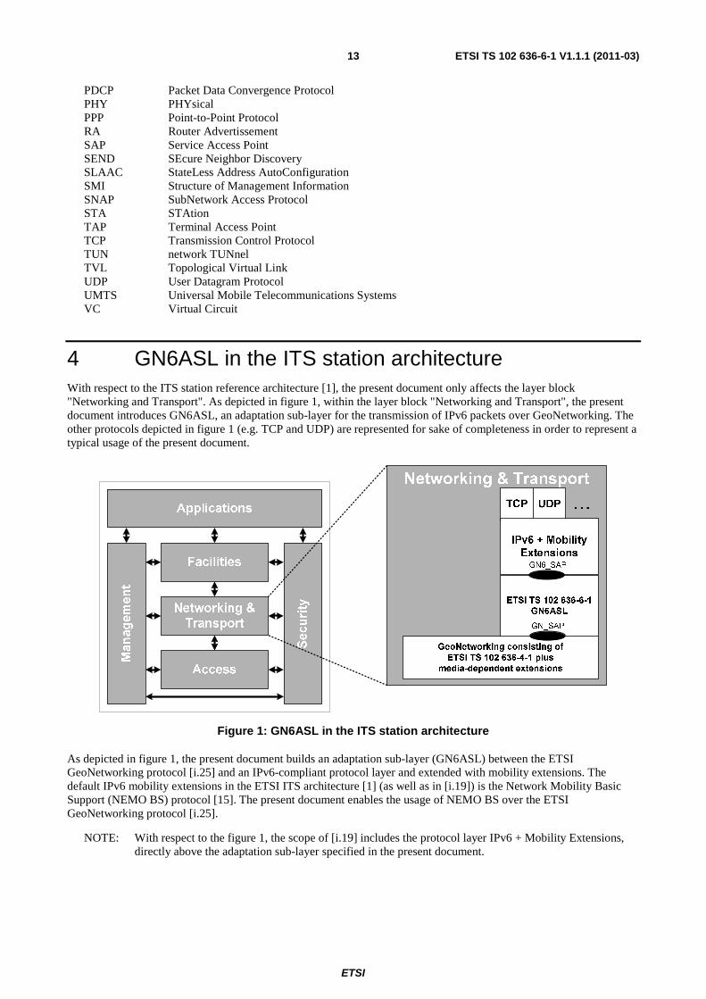
4 GN6ASL in the ITS station architecture With respect to the ITS station reference architecture [1], the present document only affects the layer block "Networking and Transport". As depicted in figure 1, within the layer block "Networking and Transport", the present document introduces GN6ASL, an adaptation sub-layer for the transmission of IPv6 packets over GeoNetworking. The other protocols depicted in figure 1 (e.g. TCP and UDP) are represented for sake of completeness in order to represent a typical usage of the present document.
Figure 1: GN6ASL in the ITS station architecture
As depicted in figure 1, the present document builds an adaptation sub-layer (GN6ASL) between the ETSI GeoNetworking protocol [i.25] and an IPv6-compliant protocol layer and extended with mobility extensions. The default IPv6 mobility extensions in the ETSI ITS architecture [1] (as well as in [i.19]) is the Network Mobility Basic Support (NEMO BS) protocol [15]. The present document enables the usage of NEMO BS over the ETSI GeoNetworking protocol [i.25].
NOTE: With respect to the figure 1, the scope of [i.19] includes the protocol layer IPv6 + Mobility Extensions, directly above the adaptation sub-layer specified in the present document.

ETSI
ETSI TS 102 636-6-1 V1.1.1 (2011-03) 14
5 IPv6 link models and interfaces
5.1 Rationales The Neighbor Discovery (ND) protocol [10] is a mandatory part of IPv6 stacks that includes functionalities like Router and Prefix Discovery as well as Address Resolution and Neighbor Unreachability Detection. Some of ND's services use link-layer multicast addresses. This implies that the link-layer protocol is required to support multicast addressing in order to run the ND protocol as described in [10]. ND adaptations or alternative protocols or mechanisms to implement its services are commonly introduced for link-layer technologies that do not support multicast addressing (e.g. [18], [i.4], [i.5]).
GN6ASL is presented to the IPv6 layer as a link-layer protocol which relies on GeoNetworking [i.25]. GeoNetworking provides both point-to-point and point-to-multipoint communications, as well as geographically scoped addressing like GeoAnycast and GeoBroadcast [4]. Furthermore, [i.25] provides upper layers with a sub-IP multi-hop delivery service as required by [3].
NOTE: "sub-IP multi-hop delivery" is defined in clause 3.1.
When IPv6 makes use of the sub-IP multi-hop delivery service provided by ETSI GeoNetworking protocol [i.25] via GN6ASL, virtual links are used that span multiple physical links. These virtual links are modelled and characterized in the present document such that they can be utilized by an IPv6-compliant protocol layer. In particular, link-layer multicast support in a virtual link that spans multiple physical links requires symmetric reachability (defined in [10]) be satisfied by the virtual link. Virtual links for mobile ad-hoc networks that define the virtual link's boundary based on the number of hops do not provide symmetric reachability in mobile environments due to the changing network topology. GN6ASL provides virtual links that present symmetric reachability, since the virtual links' boundaries are defined as geographical coordinates.
The present document introduces two types of virtual link, one designed to be link-local multicast capable by means of geographically scoped boundaries and the other one with no link-local multicast support but not subject to geographic boundaries. The combination of these two types of virtual link in the same station allows running the ND protocol including SLAAC [12] as well as to distribute other IPv6 link-local multicast traffic and, at the same time, to reach nodes that are outside specific geographic boundaries. The two properties are split up in two different virtual link types in order to maintain full compliance with the link properties required by ND.
EXAMPLE: In 3GPP Release 9, IPv6 is transported directly over PDCP, and optionally via PPP [i.21]. In both cases, over PDCP and via PPP, virtual point-to-point links are used. [i.21] uses some ND operations like the issuing of a Router Solicitation although, as pointed out in [i.7], the IETF has not specified a point-to-point architecture and how the standard IPv6 address assignment mechanisms are applicable to IPv6 over point-to-point links. [i.7] called for the (at that time still existing) IPv6 WG to carry out these activities but to date no specification exists. Consequently, whenever possible, it is recommended to provide link-local multicast capable virtual links, which is achieved in the present document by means of a geographically scoped virtual link.
In the followings, virtual links are distinguished from virtual interfaces. A virtual interface represents an instance of a virtual link that is presented to the IPv6 layer in an implementation-specific way. Compliance to the present document is required for virtual links but not for virtual interfaces, being virtual interfaces an implementation-specific way to provide virtual links. For this reason, the following sections distinguish between required and recommended properties. However, the properties and usage of virtual interfaces as described in the present document maximize backward compatibility with pre-existing IPv6-compliant implementations, such that these implementations can be used over GN6ASL.
It should be noted that the specific virtual interface chosen by an implementation does not affect the encapsulation method nor the link properties. Further, the emulation operated by a virtual interface shall maintain the link properties (e.g. with respect to symmetric reachability). Therefore, the issues described in [i.3] do not arise.
ETSI
ETSI TS 102 636-6-1 V1.1.1 (2011-03) 15
5.2 Required properties of supported IPv6 link models
5.2.1 Number and types of virtual link
GN6ASL of a Geoadhoc router shall support at least one Geographical Virtual Link (GVL) as defined in clause 5.2.2 and exactly one Topological Virtual Link (TVL) as defined in clause 5.2.3.
EXAMPLE: An example implementation of virtual links and virtual interfaces is described in clause E.1.
5.2.2 Geographical virtual links
A Geographical Virtual Link (GVL) is a link-local multicast-capable virtual link spanning multiple physical links with geographically scoped boundaries.
Each GVL shall be associated with one single GeoNetworking GEOBROADCAST/GEOANYCAST area (also called geoarea in [i.25] and specified in [6]) stored in the per-GVL MIB attributes itsGn6aslGvlAreaCenterLatitude itsGn6aslGvlAreaCenterLongitude itsGn6aslGvlAreaDistA itsGn6aslGvlAreaDistB itsGn6aslAreaAngle. These attributes are referred to as the GVL Area and shall be:
• derived from a received GeoNetworking header encapsulating a Router Advertisements (RA) messages [10] as described in clause 10.2.1; or
• assigned by the ITS station management entity.
IPv6 ND shall be supported by GVLs with the amendments specified in clause 10.
A GVL is shared among several Geoadhoc routers when all of the Geoadhoc routers use the same GVL area.
The per-link MIB attributes of a GVL are specified in annex B.
5.2.3 Topological virtual links
A Topological Virtual Link (TVL) is a non-broadcast multi-access (NBMA) virtual link spanning multiple physical links with topologically scoped boundaries. IPv6 multicast traffic may not be exchanged through a TVL.
An interface associated to a TVL shall only be assigned the IPv6 link-local unicast address [9] and no other IPv6 addresses.
The per-link MIB attributes of a TVL are specified in annex B.
5.3 Recommended properties of virtual interfaces
5.3.1 Number and types of virtual interfaces
The IPv6 virtual link types described in clause 5.2 should be provided by GN6ASL to IPv6 in the form of virtual network interfaces.
Virtual network interfaces can be associated to either GVLs or TVLs. A single virtual interface can only be associated to one GVL or one TVL. One or several virtual interfaces can be associated to one single physical interface (e.g. an ITS-G5 [2] physical interface). Given a physical interface:
• only one TVL can be associated to the physical interface and only one virtual interface can be associated to that TVL;
• multiple GVLs can be associated to the physical interface and only one virtual interface can be associated to each GVL.
ETSI
ETSI TS 102 636-6-1 V1.1.1 (2011-03) 16
In order to allow for backward compatibility with pre-existing IPv6 protocol implementations, as well as to support IEEE 802-based passing bridge IPv6 packets, GN6ASL should support at least virtual network interfaces of the type Ethernet V2.0/IEEE 802.3 [32] LAN in the way described in clause 5.3.2.1. Geoadhoc routers can also support other types of virtual interfaces.
Virtual interfaces used to implement GVLs and TVLs and the underlying operating system should support bidirectional communications. This is required in order to maintain symmetric reachability in a GVL. This recommendation originates from the implementation experience offered by the European GeoNet project (more references in clause E.4).
5.3.2 Usage of specific virtual interfaces
5.3.2.1 Ethernet V2.0/IEEE 802.3 LAN virtual interfaces
Virtual network interfaces of type Ethernet V2.0/IEEE 802.3 LAN [32] should be supported by GN6ASL for the transmission of IPv6 packets over GeoNetworking protocol [i.25]. Virtual network interfaces of the type Ethernet V2.0/IEEE 802.3 LAN should only be associated to GVLs, since TVLs do not support native link-layer multicast/broadcast.
The transmission of IPv6 packets over GeoNetworking protocol [i.25] via Ethernet V2.0/IEEE 802.3 LAN virtual interfaces should be compliant with [17] regarding all operations undertaken by IPv6. The alternative encapsulation method described in [25] and utilizing the 802.2 Sub-Network Access Protocol (SNAP) header extension should not be used. In any case, as depicted in figure 3, no virtual interface-specific protocol header may be added between the GeoNetworking header(s) and the IPv6 header. Thus, the issues described in [i.3] do not arise.
The MAC address of a virtual interface of type Ethernet V2.0/IEEE 802.3 LAN should be derived from the 48-bit M_ID field of the GN_Addr [i.25] of the local Geoadhoc router. Consequently, the IID part of IPv6 addresses generated by means of SLAAC as described in clause 10.2.1 for virtual Ethernet V2.0/IEEE 802.3 LAN also embeds the M_ID. According to [i.25], clause 6.3, second note, the address space of GN_Addr is 48 bits long. This means that the IID derived in this way maps to one and only one GN_Addr.
NOTE: In order to protect the user's privacy, GN_Addr may be modified upon a request of the ITS station management entity. This implies that the IPv6 address shall be modified accordingly. See clause 11.2.
EXAMPLE: Examples of virtual interfaces of type Ethernet V2.0/IEEE 802.3 LAN are TAP virtual devices which are supported by several operating systems [i.15] and are also adopted by the prototype implementations of the European project GeoNet [i.18].
5.3.2.2 NBMA virtual interfaces
Virtual network interfaces of any type recognized by IPv6 as NBMA link can be adopted by GN6ASL for the transmission of IPv6 packets over GeoNetworking protocol [i.25]. Virtual network interfaces of the type NBMA should only be associated to TVLs.
The transmission of IPv6 packets over NBMA virtual interfaces should be compliant with [18], clause 4.4.1. If the virtual interface does not use LLC/SNAP encapsulation, the amendments specified in the NBMA-specific companion document of [18] should apply. Since TVLs provide a connectionless service, a point-to-point Virtual Circuit (VC) between two arbitrary nodes should be considered to implicitly exist and no VC call shall be placed. Further, convergence protocols like [24] are not necessary because IPv6 link-local multicast is not allowed on TVLs.
The non-ND-based address resolution specified in clause 10.3.1 should be used on NBMA virtual interfaces.
5.3.2.3 Point-to-point virtual interfaces
Virtual network interfaces of type point-to-point can be adopted by GN6ASL for the transmission of IPv6 packets over GeoNetworking protocol [i.25]. Virtual network interfaces of the type point-to-point should only be associated to TVLs.
Virtual point-to-point interfaces are commonly provided as part of various operating systems for VPN tunnelling. Virtual point-to-point interfaces differ from physical point-to-point network interfaces (e.g. GPRS and UMTS [i.4]) in that they are an abstraction of point-to-point links and do not require link-layer adaptation protocols like PPP [i.8]. Consequently, when virtual point-to-point interfaces are adopted for the transmission of IPv6 packets via GN6ASL, the mechanisms described in [19] are not necessary and should not be used.
ETSI
ETSI TS 102 636-6-1 V1.1.1 (2011-03) 17
A point-to-point virtual interface that does not support native broadcast/multicast should be used as a pre-configured NBMA point-to-point VC and the transmission of IPv6 packets over GeoNetworking protocol via this type of virtual interface should be compliant to clause 5.3.2.2.
Some IPv6 implementations in conjunction with specific point-to-point virtual interface implementations, like [i.15], allow for the transmission of IPv6 link-local multicast traffic over a point-to-point virtual interface. As pointed out in the example in clause 5.1, although [i.7] called for the (at that time still existing) IPv6 WG to produce one, to date no specification
exists which describes how IPv6 link-local multicast traffic should be transmitted on a point-to-point (virtual) link. Therefore existing IPv6 implementations might not issue IPv6 link-local multicast traffic on point-to-point virtual interfaces. Consequently, it is recommended to associate point-to-point virtual interfaces only to TVLs and use other types of virtual interfaces (like Ethernet V2.0/IEEE 802.3 LAN) on GVLs.
EXAMPLE: TUN virtual devices, supported by several operating systems [i.15], are adopted by the reference implementations of the European project GeoNet [i.18] for both unicast and link-local multicast IPv6 traffic. Experiences in this project have shown that the Linux IPv6 stack allows link-local multicast traffic to be issued on point-to-point virtual interfaces. Since this is not a standard-based behaviour, other IPv6 implementations might behave differently.
6 Bridging support
6.1 Rationales In the ETSI ITS network architecture [5], an access router provides an ad hoc network with access to the Internet (see [5], Figure 3). The GeoNetworking protocol [i.25] and the GN6ASL are implemented by the Geoadhoc router.
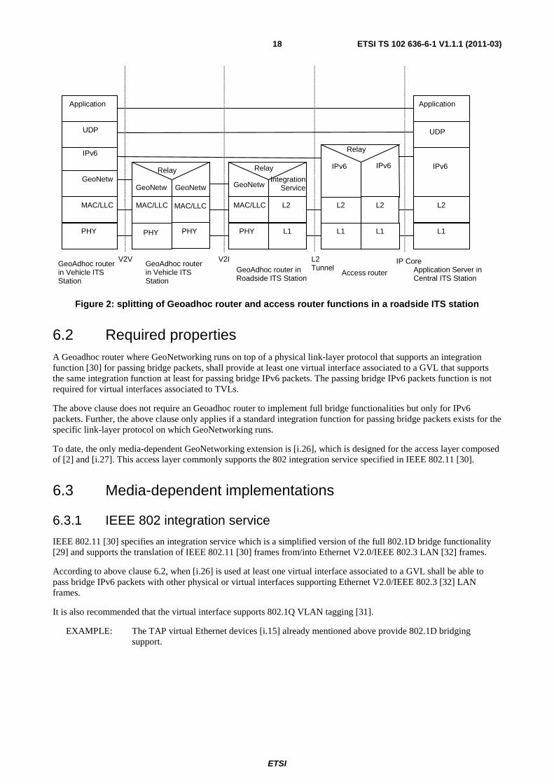
According to [5] clause 6.2, the Geoadhoc router and the access router are two separate logical network components that optionally collapse into one single component of an ITS station. If these functions are collapsed, the access router directly terminates the GeoNetworking protocol transport of IPv6 packets and no additional transport function is required. If Geoadhoc router and the access router are in two separate components (see Figure 2), it is necessary to extend the transport termination from the Geoadhoc router to the access router.
Since the transport of IPv6 packets has to be extended without modifying the IPv6 packets, a link-layer or a tunnelling transport mechanism shall be adopted. The present document provides a link-layer mechanism based on bridging that is specified in clause 6.2.
EXAMPLE: When a roadside ITS station provides vehicle ITS stations with connectivity to the Internet, vehicle ITS stations select the access router as the IPv6 default gateway (and therefore as IPv6 next hop for all IPv6 traffic targeted to addresses determined to be off-link). GeoNetworking protocol transport of IPv6 packets terminates in the Geoadhoc router of a roadside ITS station. The separation of Geoadhoc router and access router (see Figure 2) allows for diversified deployment scenarios. In fact, the access router is not required to reside in the roadside ITS station but could be physically located far away from the road, e.g. in a traffic control operations center. A layer-2 tunnel transport technology can be adopted to connect a roadside ITS station with the access network where the access router resides.
ETSI
ETSI TS 102 636-6-1 V1.1.1 (2011-03) 18
Access router Application Server in Central ITS Station
IP Core
MAC/LLC
PHY PHY
GeoNetw GeoNetw
Relay
GeoNetw
L2
Relay
MAC/LLC
PHY L1
IPv6 IPv6
L2
Relay
L2
L1 L1
IPv6
GeoNetw
MAC/LLC
PHY
UDP
Application
IPv6
L2
L1
UDP
Application
L2 Tunnel
V2I V2V GeoAdhoc router in Roadside ITS Station
GeoAdhoc router in Vehicle ITS Station
GeoAdhoc router in Vehicle ITS Station
MAC/LLC
IntegrationService
Figure 2: splitting of Geoadhoc router and access router functions in a roadside ITS station
6.2 Required properties A Geoadhoc router where GeoNetworking runs on top of a physical link-layer protocol that supports an integration function [30] for passing bridge packets, shall provide at least one virtual interface associated to a GVL that supports the same integration function at least for passing bridge IPv6 packets. The passing bridge IPv6 packets function is not required for virtual interfaces associated to TVLs.
The above clause does not require an Geoadhoc router to implement full bridge functionalities but only for IPv6 packets. Further, the above clause only applies if a standard integration function for passing bridge packets exists for the specific link-layer protocol on which GeoNetworking runs.
To date, the only media-dependent GeoNetworking extension is [i.26], which is designed for the access layer composed of [2] and [i.27]. This access layer commonly supports the 802 integration service specified in IEEE 802.11 [30].
6.3 Media-dependent implementations
6.3.1 IEEE 802 integration service
IEEE 802.11 [30] specifies an integration service which is a simplified version of the full 802.1D bridge functionality [29] and supports the translation of IEEE 802.11 [30] frames from/into Ethernet V2.0/IEEE 802.3 LAN [32] frames.
According to above clause 6.2, when [i.26] is used at least one virtual interface associated to a GVL shall be able to pass bridge IPv6 packets with other physical or virtual interfaces supporting Ethernet V2.0/IEEE 802.3 [32] LAN frames.
It is also recommended that the virtual interface supports 802.1Q VLAN tagging [31].
EXAMPLE: The TAP virtual Ethernet devices [i.15] already mentioned above provide 802.1D bridging support.
ETSI
ETSI TS 102 636-6-1 V1.1.1 (2011-03) 19
7 IPv6/GeoNetworking interface service specification The services offered by GN6ASL to IPv6 are delivered through GN6_SAP which is designed based on the service user/provider model described in [28].
GN6_SAP shall only provide unacknowledged connectionless-mode services to IPv6, which consist of a set of data transfer services by which IPv6 protocol entities of different Geoadhoc routers can exchange IPv6 packets without the establishment of data link level connections.
The primitives associated with the data transfer services provided by GN6_SAP are as follows:
• GN6-UNITDATA.request
• GN6-UNITDATA.indication
The GN6-UNITDATA.request primitive is passed by GN6ASL to request that a GN6SDU be sent using unacknowledged connectionless-mode procedures. The GN6-UNITDATA.indication primitive is passed to IPv6 to indicate the arrival of an IPv6 header.
The primitives parameters are specified in the informative annex C.
8 Encapsulation characteristics
8.1 Maximum transmission unit The MTU of a virtual interface associated to a GVL or TVL (MTUGN6) shall be set to a value that depends on the MTU of the access layer technology that transports the GeoNetworking protocol (MTUAL). In particular, MTUGN6 shall be less or equal to MTUAL reduced by the size of the largest GeoNetworking protocol header used to transport IPv6 packets (GEOMAX, corresponding to itsGnMaxGeoNetworkingHeaderSize in ITSGN-MIB [i.25]) and by the size of the largest GeoNetworking Security header (GEOSECMAX). Moreover, MTUGN6 shall also be less or equal to the typical MTU supported by the specific type of virtual interface MTUVI.
The previous clause is expressed by the following equation.
},min{6 MAXMAXALVIGN GEOSECGEOMTUMTUMTU −−= (1)
Since the minimum required MTU by IPv6 is 1280 octets, IPv6 over GeoNetworking is enabled only when the access layer is such that:
MAXMAXAL GEOSECGEOMTU ++≥ 1280 (2)
EXAMPLE: When the media-dependent extension [i.26] is used, the access layer is given by the combination of [2] and [i.27] (i.e. ITS-G5 PHY, MAC and LLC). This combination is expected to result in a MTUAL bigger than 2000 octets, similarly to the combination of [30] and [28]. This guarantees not only that the condition expressed by equation 2 is fulfilled, but also that the Ethernet MTU (1500) is supported, as soon as the sum GEOMAX + GEOSECMAX is smaller than 720 octets. This condition is expected to be met by far.
8.2 Packet delivery
8.2.1 Outbound traffic
The following list describes the steps that shall be undertaken by the GN6ASL upon the transmission of an IPv6 packet over GeoNetworking. The procedure applies to both IPv6 packets generated by the ITS station itself or being forwarded by the IPv6 protocol layer residing in the ITS station.

ETSI
ETSI TS 102 636-6-1 V1.1.1 (2011-03) 20
The following procedure only describes the logical steps that shall be undertaken by the GN6ASL and not the steps undertaken by the virtual interfaces (implementation-specific). An example of virtual interface operations is provided in clause E.2.
Procedure:
1) Preliminary IPv6 operations: the IPv6 layer shall execute the ordinary procedures according to the IPv6 base specifications [7], [16]. These procedures include IPv6 header assembling, Routing and Forwarding Information Bases lookup, outgoing interface selection, and source address selection. These procedures are outside the scope of the present document. If the selected outgoing interface is one of the virtual interfaces associated to a GVL or TVL provided by the GN6ASL, the next steps shall be executed.
NOTE 1: The IPv6 protocol layer does not distinguish an interface associated to a GVL/TVL from any other interface. However, an interface associated to a GVL/TVL may be automatically selected if the default route is associated to that interface, e.g. as a consequence of SLAAC as described in clause 10.2.1. Alternatively, proper configuration of the IPv6 routing table is required, which is outside the scope of the present document.
2) The GN6ASL shall perform a check on the source IPv6 address. If the address was automatically configured via SLAAC (clause 10.2.1) and the IID part of the address does not match the current GN_Addr of GeoNetworking, the packet shall be silently discarded by the GN6ASL.
NOTE 2: The above check is required in order to preserve the effectiveness of the pseudonym change mechanism to preserve the user's privacy. See clause 11.2 for more details.
3) The link-layer destination address resolution shall be performed according to the procedures specified in clause 10.3. After completion of address resolution, IPv6 shall invoke GN6-UNITDATA.request.
4) Upon a GN6-UNITDATA.request primitive call, the GN6ASL shall determine the set of parameters to be passed to GeoNetworking as specified in table 1. In particular:
a. If the destination address parameter of GN6-UNITDATA.request is a IPv6 unicast address, the GN6ASL shall univocally derive the M_ID part of a unicast GN_Addr from it.
b. If the destination address parameter of GN6-UNITDATA.request is a IPv6 multicast or anycast address, the GN6ASL shall apply the procedures described in clause 9.2.1 or 9.3, respectively.
5) The GN6ASL shall invoke the GeoNetworking GN-Data.request service primitive with the parameters determined in the previous step.
NOTE 3: In various implementations of IPv6, the link-layer SAP invocation is implemented by IPv6 passing down a partially filled link-layer header. If such an implementation is used to deploy the GN6ASL, it should be noted that the link-layer header appended by IPv6 depends on the virtual interface type and is to be removed by the GN6ASL.
ETSI
ETSI TS 102 636-6-1 V1.1.1 (2011-03) 21
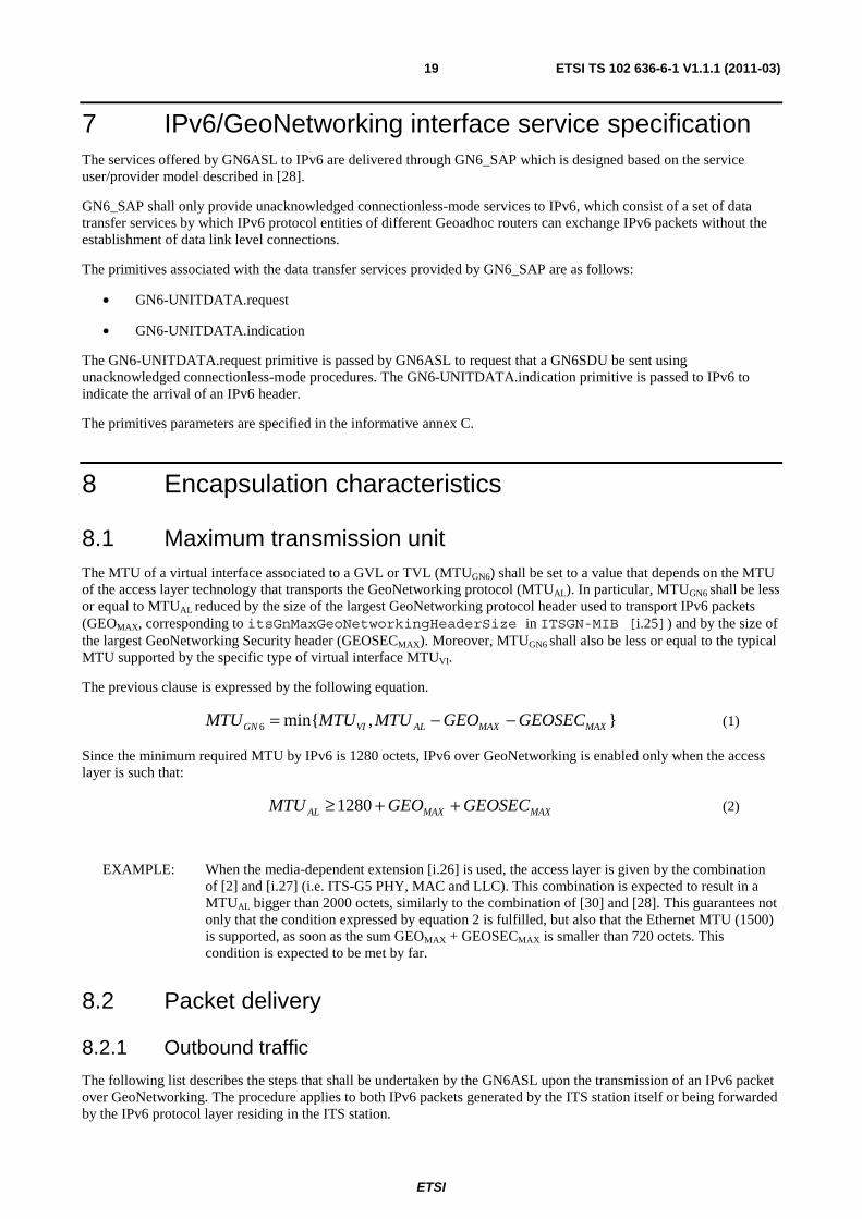
Table 1: Service primitive parameter determination for outbound traffic
GN-Data.request primitive parameter
Value set by the GN6ASL If GN6-UNITDATA.request is
called with IPv6 unicast destination address
If GN6-UNITDATA.request is called with IPv6 multicast
destination address Packet transport type GeoUnicast GeoBroadcast Destination GN_Addr consisting of M_ID
derived from the destination IPv6 address received in GN6-UNITDATA.request and remaining fields set to 0
GVL Area (see clause 9.2.1) of the outgoing virtual link
Maximum lifetime 0 Repetition interval 0 Traffic class (see note 1) 0x0F if priority < 64
0x0E if 63 < priority < 128 0x0D if 127 < priority < 192 0x0C if priority > 193
Length Length of the GN6SDU Data The GN6SDU passed to GN6-UNITDATA.request NOTE 1: As explained in [i.25], clause 6.3, the address space of GN_Addr is 48-bits wide, i.e. the
M_ID field alone is sufficient to univocally identify a Geoadhoc router. The GeoNetworking protocol recognizes that the destination parameter of the GN-Data.request primitive only contains the M_ID field. The GeoNetworking protocol is responsible for deriving a full GN_Addr from the M_ID.
NOTE 2: At the time of writing the present document, no specification exists that mandates a certain usage of link-layer QoS facilities for IPv6. For example EDCA Access Categories are selected in implementation-specific ways for IPv6 over 802.2 LLC [28] over 802.11 MAC/PHY [30] by checking the traffic class field of the IPv6 header [7]. The present document provides IPv6 with the priority primitive parameter for similar purposes. Mapping between IPv6 traffic class field values and the priority primitive parameter is outside the scope of the present document. The present table only specifies the mapping between the primitive parameter and the GeoNetworking traffic class field.
8.2.2 Inbound traffic
The following list describes the steps that shall be undertaken by the GN6ASL upon the reception of a GeoNetworking header transporting an IPv6 header.
The following procedure only describes the logical steps that shall be undertaken by the GN6ASL and not the steps undertaken by the virtual interfaces (implementation-specific). An example of virtual interface operations is provided in clause E.2.
Procedure:
1) Preliminary GeoNetworking operations: the GeoNetworking protocol header shall perform the regular operations described in [i.25] regarding header checks, optional security checks, update of data structures and packet forwarding. If the Geoadhoc router belongs to the addressed stations and the NH field of the GeoNetworking header notifies the presence of an IPv6 header, the GN6ASL shall be notified via a GN-Data.indication primitive call and execute the next steps.
2) Virtual link selection: in this step, the GN6ASL determines which virtual link the packet belongs to.
a. If the GeoNetworking header is of type GEOBROADCAST/GEOANYCAST, the GN6ASL shall first check if a GVL exists in the itsGn6aslVLTable whose GVL Area matches the destination area specified in the GEOBROADCAST/GEOANYCAST header. If such a GVL exists, it should be selected as inbound virtual link. If such a GVL is not found and the GEOBROADCAST/ GEOANYCAST header carries an IPv6 Router Advertisement, a new GVL link shall be created as specified in clause 10.2.1 and selected as inbound virtual link. If the GEOBROADCAST/GEOANYCAST header does not carry an IPv6 Router Advertisement and a GVL with the same GVL Area does not exist in the itsGn6aslVLTable, the packet shall be silently discarded.
ETSI
ETSI TS 102 636-6-1 V1.1.1 (2011-03) 22
b. If the GeoNetworking header is of type GEOUNICAST, the GN6ASL shall check the IPv6 destination address scope of the IPv6 header transported by the GEOUNICAST. If the IPv6 destination address is the link-local unicast address FE80 ::<IID>/10, the GN6ASL shall select the TVL as inbound virtual link. If the IPv6 destination address has a scope greater than link-scope and no GVL exists in the itsGn6aslVLTable whose GVL Area contains the GeoNetworking source node's position, the GN6ASL shall silently discard the packet. If the IPv6 destination address has a scope greater than link-scope and one or more GVLs exist in the itsGn6aslVLTable whose GVL Area contains the GeoNetworking source node's position, the GN6ASL shall, among those GVLs, select one (if present) that is associated to a virtual interface for which the IPv6 destination address prefix is considered to be on-link. If the IPv6 destination address prefix is considered to be on-link for more than one GVL, the GVL associated to the prefix with the highest invalidation timer value in the Prefix List [10], [11] shall be selected as inbound GVL. If no GVL exists in the itsGn6aslVLTable that matches the above criteria, the packet shall be silently discarded.
NOTE 1: The IPv6 on-link determination is defined in [10] and updated in [11]. Checking if a prefix is considered to be on-link for a certain interface corresponds to checking the IPv6 Prefix List or ipv6AddrPrefixTable in the IPv6 MIB [27]. See clause 10.1 for on-link determination.
NOTE 2: According to other IPv6 deployments [i.2], it is recommended to avoid that a prefix is considered to be on-link for multiple links. The present document also recommends to avoid this situation by proper IPv6 prefixes assignment and access router configuration. In particular, clause 10.2.1 recommends that the same prefix is not advertised in a Router Advertisement Prefix Information option with the L-bit set on different GVLs by one or more IPv6 routers.
3) The GN6ASL shall invoke the GN6-UNITDATA.indication primitive.
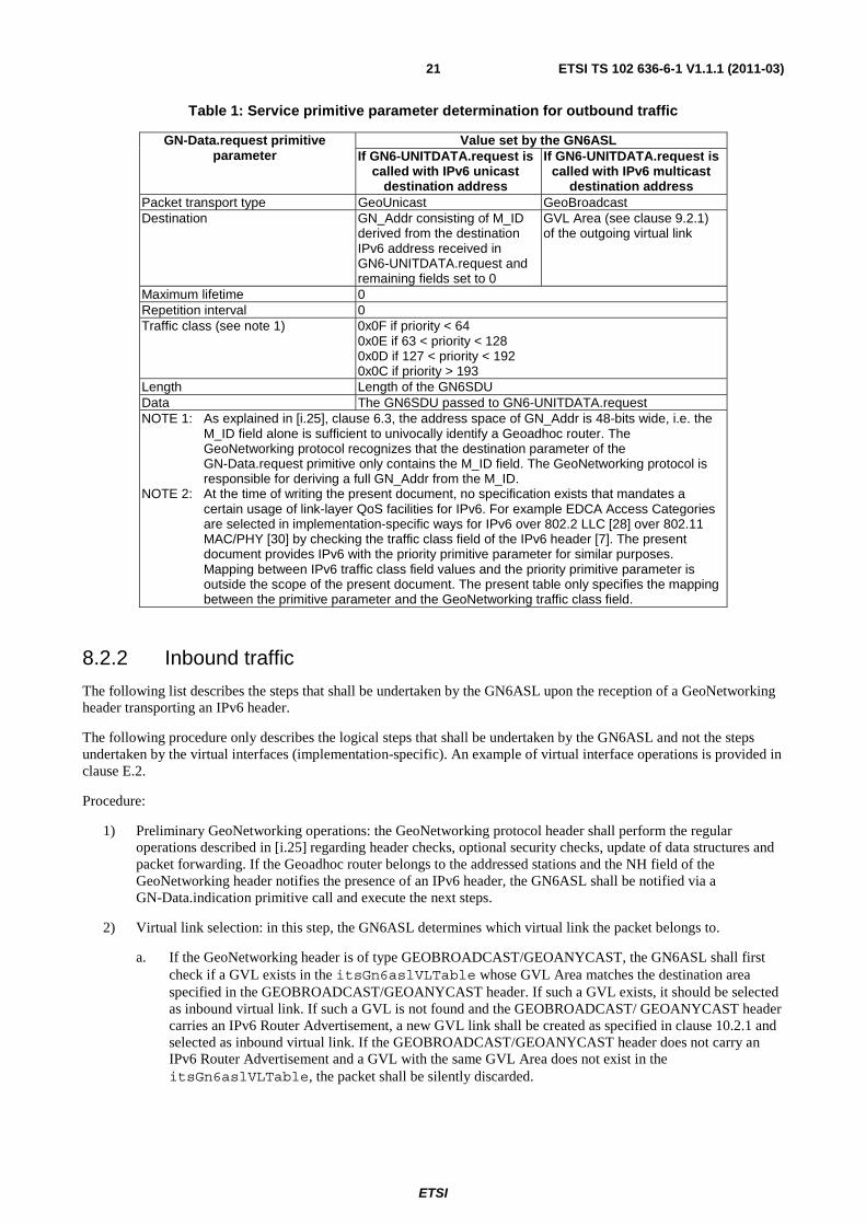
8.3 Frame format The present document does not introduce new frame formats. Neither modifications to the IPv6 headers defined in [7], [8], [9], [10] and [12] are introduced, nor changes to the format of the GeoNetworking header [i.25] are amended. The structure of GeoNetworking header transporting an IPv6 header and its payload is derived by appending the IPv6 header and its payload to the GeoNetworking header directly or after an optional GeoNetworking security header. The resulting packet is represented in Figure 3 from the perspective of the physical layer.
The format of the GeoNetworking header is defined in [i.25].
MAC Header
LLC Header
GeoNetworking Header
GeoNetworking Security Header
(optional)
IPv6 Header
IPv6 Payload
(optional)
MAC Trailer
(optional)
Figure 3: generic packet format of an IPv6 header and payload transported by GeoNetworking
EXAMPLE 1: As shown in Figure 4, the IPv6 Payload field depicted in Figure 3 can consist of IPv6 extension headers, followed by a transport header and the transport protocol payload.
IPv6 Extension Header(s)
Transport Header (UDP, TCP, other
transport protocols)
Transport Payload
Figure 4: generic packet format of an IPv6 header and payload transported by GeoNetworking
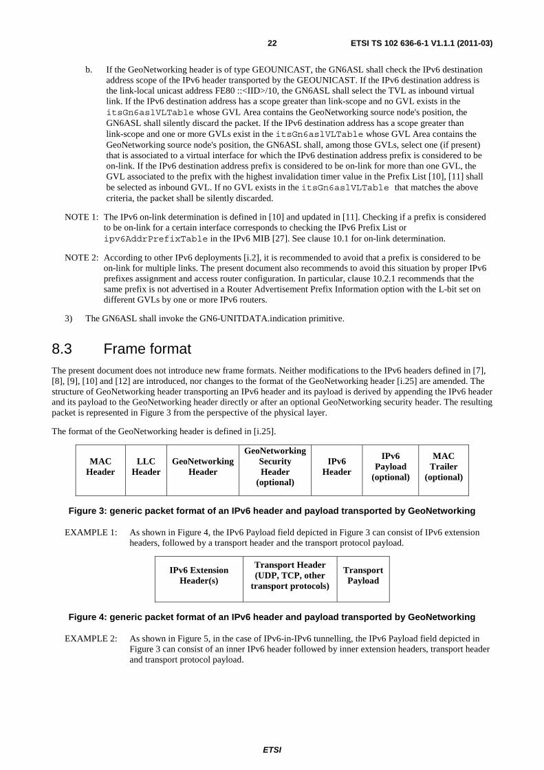
EXAMPLE 2: As shown in Figure 5, in the case of IPv6-in-IPv6 tunnelling, the IPv6 Payload field depicted in Figure 3 can consist of an inner IPv6 header followed by inner extension headers, transport header and transport protocol payload.
ETSI
ETSI TS 102 636-6-1 V1.1.1 (2011-03) 23
IPv6 Inner Header IPv6 Inner Extension
Header(s)
Transport Header (UDP, TCP, other
transport protocols)
Transport Payload
Figure 5: generic packet format of an IPv6 header and payload transported by GeoNetworking
9 IPv6 multicast and anycast support
9.1 Overview This clause describes how legacy IPv6 multicast addressing is supported over GeoNetworking. In this context, legacy refers to non-geographic IPv6 multicast addressing, i.e., multicast addresses that are created according to IPv6 specifications and that do not embed any sort of specification of a geographical area. Geographic IPv6 multicast, instead, is an experimental type of IPv6 multicast addressing studied by the European GeoNet project [i.17] where IPv6 addresses contain an encoding of geographical areas. Geographic IPv6 multicast support is affected by drawbacks and is therefore considered experimental and described in annex D for informative purposes.
Unlike geographic IPv6 multicast described in annex D, the mechanisms specified in clause 9.2.3 allow for geocasting of IPv6 multicast traffic by hiding the geographic addressing from IPv6. Consequently, these mechanisms can be easily deployed as they do not require changes to existing IPv6 protocol implementations.
9.2 Legacy IPv6 multicast support
9.2.1 IPv6 link-local multicast
IPv6 link-local multicast traffic shall be transmitted via the GN6ASL only on GVLs. IPv6 link-local multicast traffic shall not be transmitted via the TVL. As specified in clause 5.2.2, each GVL is associated to a geographical area specified by its GVL Area. An outgoing IPv6 packet with a link-local multicast destination address shall be transmitted by GeoNetworking in a GEOBROADCAST header ( [i.25], clause 6.5.4). The fields describing the destination area of the GEOBROADCAST header shall be set to the values of the equivalent fields of GVL Area of the outgoing GVL.
NOTE: GeoNetworking [i.25] GEOBROADCAST/GEOANYCAST headers do not contain a destination GN_Addr by design. This implies that the group ID of an IPv6 multicast address is not encapsulated into a sub-IP layer address that is actually transmitted (link-layer headers of virtual interfaces are removed before sending, see NOTE2 in clause 8.2.1). Consequently, all IPv6 multicast/anycast traffic will be received by every Geoadhoc router attached to the GVL and the IPv6 layer will filter out incoming IPv6 multicast packets whose target groups it has not joined.
EXAMPLE 1: In an exemplary implementation using virtual interfaces of type Ethernet V2.0/IEEE 802.3 LAN, an outgoing IPv6 packet with a IPv6 link-local multicast destination can be recognized by the GN6ASL implementation from the first 2 bytes of the destination MAC address that are set to 0x3333 according to [17].
The behaviour described above shall apply to any outgoing IPv6 packets with IPv6 link-local multicast addresses, including pre-defined, permanently and non-permanently assigned addresses.
EXAMPLE 2: The "all nodes on-link multicast IPv6 address" (FF02::1/16), which is particularly important for SLAAC (clause 10.2.1) belongs to this category and is subject to the processing described in this section.
The IPv6 layer of an ITS station implementing the present document should support the MLDv2 protocol specified in [20] for group membership management. Based on the distribution of IPv6 link-local multicast traffic described above, distribution of MLDv2 signalling messages on GVLs is fully supported. However, bandwidth-sensitive and highly-mobile technology-specific deployments may be required to limit or even completely disable any IPv6 multicast group membership management.
ETSI
ETSI TS 102 636-6-1 V1.1.1 (2011-03) 24
9.2.2 IPv6 wider-scope multicast
IPv6 multicast traffic with scope wider than link-local may be transmitted over GeoNetworking only on GVLs.
The GN6ASL specified in the present document is affected by the transmission of wider-scope IPv6 multicast traffic only with regard to the multicasting of this traffic on a GVL. In fact, the IPv6 protocol layer above the GN6ASL deals with forwarding of IPv6 multicast traffic. Should the IPv6 layer determine that this traffic is to be distributed to GVL on-link nodes (e.g. by one access router of the GVL), the GN6ASL shall utilize the same technique as for IPv6 link-local multicast traffic described in clause 9.2.1, i.e. the traffic shall be transmitted by GeoNetworking in a GEOBROADCAST header.
Standard IPv6 mechanisms for IPv6 multicast traffic forwarding [21], [22] are expected to work properly on the virtual links provided by GeoNetworking. However, their usage is deployment-dependent and an ITS station implementing the present document may also not support these protocols. In particular, bandwidth-sensitive and highly-mobile technology-specific deployments may be required to limit or even completely disable any signalling caused by IPv6 multicast forwarding mechanisms.
9.2.3 Geocasting of legacy IPv6 multicast traffic
Based on the properties of GVLs, it is possible to realize geocasting of IPv6 traffic without introducing new IPv6 multicast groups or address types. Both link-local and wider-scope multicast IPv6 traffic can be used. With the first, any Geoadhoc router attached to a shared GVL can geocast IPv6 traffic by simply addressing the "all nodes on link" IPv6 pre-defined address FF02::1/16 [8]. With the latter, wider-scope IPv6 multicast traffic originated by remote hosts can be distributed to all nodes on a GVL link, once it has reached a router attached to the GVL which supports multicast forwarding.
NOTE: According to clause 9.2.1 anyIPv6 multicast/anycast traffic sent to a GVL will be geocasted by GeoNetworking to all nodes attached to the GVL, generating an amount of load that depends on the size of the GVL Area.
EXAMPLE: A road-side ITS station providing access to a wider IPv6 network can be associated to a geographical area by enabling at least one GVL and administratively setting its GVL Area. The road-side ITS station is then capable of geocasting IPv6 traffic to the associated area. The IPv6 traffic could be generated by the road-side ITS station itself or by a remote node located in the Internet. In the latter case, several techniques are available to convey the data traffic from the remote host to the road-side ITS station. For instance, global-scoped unicast-prefix-based IPv6 multicast addresses [23] can be used to address all ITS stations in the subnet identified by the network prefix of the unicast subnet owning the multicast address, e.g. all Geoadhoc routers on the GVL. The network prefix is univocally assigned to the GVL and is the only information that a source node located in the Internet is required to know, i.e. the GVL is opaque to nodes in the Internet. Alternatively, wider-scope multicast into unicast encapsulation can be used. Another alternative is the usage of application-level protocols to instruct a road-side ITS station to issue link-local multicast traffic.
9.3 Legacy IPv6 anycast support The same procedures described in clause 9.2 for legacy IPv6 multicast traffic shall apply to IPv6 anycast traffic, with the sole difference that GEOANYCAST headers instead of GEOBROADCAST headers shall be used to transport the IPv6 packets.
ETSI
ETSI TS 102 636-6-1 V1.1.1 (2011-03) 25
10 IPv6 neighbor discovery support
10.1 On-link determination As described in the inbound traffic procedures (clause 8.2.2), both the GeoNetworking source node position (included in the Source Position Vector field of GEOBROADCAST/GEOANYCAST and GEOUNICAST packets) and the IPv6 destination address prefix are used by GN6ASL to de-multiplex IPv6 packets and select the inbound GVL. This implies that the on-link determination of a certain address for a certain virtual interface determines whether a packet is passed to the IPv6 layer or discarded.
The IPv6 on-link determination is defined in [10] and updated in [11]. IPv6 determines a prefix to be on-link if it is included in the Prefix List [10] for that link. A prefix is added to the Prefix List upon the receipt of a valid Router Advertisement (RA) that specifies a prefix with the L-bit set or via manual configuration. ITS stations compliant to the present document shall always set the L-bit when sending Router Advertisements.
IPv6 determines an address to be on-link if it is covered by one of the link's prefixes or if a neighboring router specifies the address as the target of a Redirect message (being the last two bullets of Section 2.1 in [10] deprecated by [i.11]). The same policy shall apply for GVLs. Since TVLs only transport IPv6 traffic with link-local addresses and the link-local prefix is effectively considered a permanent entry on the Prefix List [10], no on-link determination is necessary for TVLs.
10.2 Address configuration
10.2.1 Stateless address autoconfiguration
IPv6 SLAAC [12] shall be supported by ITS stations compliant to the present document. IPv6 SLAAC may only be used on GVLs. IPv6 routers issuing Router Advertisements shall always set the L-bit and the A-bit of the Prefix Information option. The same prefix should not be advertised in a Prefix Information option with the L-bit set on different GVLs by one or more IPv6 routers. If a Source Link-layer Address Option is appended to the Router Advertisement, it shall contain the link-layer address of the virtual interface associated to the GVL on which the Router Advertisement is being sent.
NOTE 1: Outgoing Router Advertisements are always addressed to the all nodes on link multicast address. According to clause 9.2.1, GN6ASL maps this address to a geographical area. As a result, Router Advertisements are geocasted, leading to the advantages pointed out in [i.22] and [i.17].
NOTE 2: The recommendation to not advertise the same prefix on different GVLs is introduced in order to avoid that an ITS station considers a prefix to be on-link on multiple GVLs, which affects the inbound GVL selection (see clause 8.2.2).
An IPv6 router issuing Router Advertisements shall have permanently configured values of the GVL Area for each GVL it is acting as a router for.
Upon the reception of a Router Advertisement, GN6ASL shall create a new GVL and assign a GVL Area equal to the destination area specified in the GEOBROADCAST header. The destination area specified in the GEOBROADCAST header is passed to the GN6ASL via the GN-DATA.indication primitive of the GN_SAP specified in [i.25], as part of the destination address primitive parameter.
The GVL Area of a GVL created as a consequence of the receipt of a Router Advertisement may not be modified. The GVL shall be destroyed whenever the invalidation timer expires for all of the Prefix List entries associated to that GVL (see [10]).
Both solicited and unsolicited Router Advertisements shall be supported. External information on the possible presence of a router, like router maps and current geographical position, may be used by an ITS station to decide upon issuing a Router Solicitation.
The IPv6 router parameters included in Router Advertisement carrying Prefix Information Options (Router Lifetime, Reachable Time, Retrans Timer, prefix Valid Lifetime and Preferred Lifetime) shall be deployment-specific. In particular, these parameters become critical in bandwidth-sensitive and highly-mobile deployments (like those envisaged for [2]). Careful parameter tuning based on field trial results should be adopted.
ETSI
ETSI TS 102 636-6-1 V1.1.1 (2011-03) 26
For any aspect of SLAAC not mentioned in this sub-clause, the standard mechanisms specified in [12] shall be used.
10.2.2 Stateful address configuration
IPv6 stateful address configuration should not be used in deployments of the present specification because of the higher latency due to the several round-trip signalling messages and the higher administrative effort required for the management of IPv6 routers.
10.2.3 Manual address configuration
In operational deployments, IPv6 addresses shall not be manually added to virtual interfaces associated to GVLs created upon the reception of a Router Advertisement. IPv6 addresses shall also not be manually added to TVLs. Manually configured addresses shall only be used with manually configured GVLs.
NOTE: The usage of manually configured addresses might decrease the effectiveness of pseudonym change schemes, as pointed out in clause G.3, and is therefore not recommended.
In experimental deployments and test environments, IPv6 addresses might be manually configured.
10.3 Address resolution
10.3.1 Non-ND-based address resolution
According to IPv6 ND [10], address resolution is performed only on non-multicast addresses that are determined to be on-link and for which the sender does not know the corresponding link-layer address. In the case of transmission of IPv6 packets via the GN6ASL, whenever the destination IPv6 address contains an IID that resolves directly to a corresponding GN_Addr and the MIB attribute itsGn6aslVIResolAddr is true, for the purpose of saving wireless resources address resolution shall be omitted and the procedure described in this clause shall be adopted.
NOTE 1: Omitting address resolution when the destination link-layer address is known to the sender is not in conflict with any IPv6 specification (see [10], clause 7.2). It should also be noted that the IPv6 implementations supporting [i.6] already omit address resolution whenever an IPv6 interface has the flag IFF_NOARP [i.6] set. The MIB attribute itsGn6aslVIResolAddr has the same meaning as IFF_NOARP specified in [i.6].
EXAMPLE: An example of IPv6 usage with direct mapping between the IPv6 address IID and the link-layer address, in which address resolution based on [10] is omitted, can be found in [i.11].
When the IPv6 non-multicast destination address contains an IID that resolves directly to a GN_Addr and the MIB attribute itsGn6aslVIResolAddr is true, IPv6 may specify any value as the destination GeoNetworking address to the ETSI GeoNetworking protocol via the GN6-UNITDATA.request primitive.
If the MIB attribute itsGn6aslVIResolAddr is true, upon a GN6-UNITDATA.request call the GN6ASL shall inspect the destination IPv6 address contained in the IPv6 header. If the destination IPv6 address is not a multicast address and contains an IID that is a 64-bit Global Identifier (EUI-64) [33], the GN6ASL shall derive the GN_Addr from the IID. The mechanism to derive the GN_Addr from the IID depends on the virtual interface type. The present document only defines it for virtual interfaces of type Ethernet V2.0/IEEE 802.3 LAN in clause 5.3.2.1.
If the MIB attribute itsGn6aslVIResolAddr is false, the GN6ASL shall not perform any address resolution and shall adopt as destination GN_Addr a value univocally derived from the destination address parameter of the GN6-UNITDATA.request primitive, which may be for example a MAC address of a type that depends on the virtual interface type. If itsGn6aslVIResolAddr is false, IPv6 shall use the ND-based address resolution procedure specified in clause 10.3 to determine the destination address parameter of the GN6-UNITDATA.request primitive.
ETSI
ETSI TS 102 636-6-1 V1.1.1 (2011-03) 27
NOTE 2: When the MIB attribute itsGn6aslVIResolAddr is false, any other mechanism compliant with IPv6 can be adopted for the purpose of avoiding unnecessary IPv6 ND signalling for address resolution (i.e. when the GeoNetworking address is known by the sender). For example, the ITS station management entity can proactively populate the IPv6 Neighbor Cache based on any traffic transported by GeoNetworking protocol, e.g. based on the protocol defined in [i.14]. A proactive population of the IPv6 Neighbor Cache will let IPv6 find the corresponding GeoNetworking address for destination addresses associated to neighboring nodes and prevents IPv6 from using ND-based address resolution.
10.3.2 ND-based address resolution
An ITS station compliant with the present document should use IPv6 addresses containing IIDs that directly resolve to GN_Addr, such that non-ND-based address resolution described in clause 10.3.1 can be applied. When this is not possible, an implementation of the present document may adopt ND-based address resolution only on virtual interfaces associated to GVLs. IPv6 addresses with IID that do not directly resolve to GN_Addr may also be used on virtual interfaces associated to GVLs.
ND-based address resolution shall be compliant to [10]. Careful tuning of ND protocol constants listed in clause 10.5 based on field tests should be adopted in order to limit the resources consumed by ND-based address resolution in highly-dynamic and resources-sensitive deployments.
10.4 Neighbor unreachability detection When IPv6 packets are transmitted over GeoNetworking via the GN6ASL, the IPv6 next hop may be several physical hops away from the source. In some deployments, e.g. where the connectivity is intermittent and available for short time intervals, frequent execution of the NUD procedure [10] is not desirable. For this reason this sub-clause introduces some specific NUD behaviour for IPv6 over GeoNetworking.
In accordance to [10], clause 7.3.3, implementations of the present document shall not have an explicit timeout event associated with the expiration of ReachableTime.
Successful bi-directional exchange of GeoNetworking packets, even if not carrying IPv6 packets, shall be used as reachability confirmation.
When an Geoadhoc router leaves the GVL Area associated to a GVL, Neighbor Cache entries corresponding to nodes on that GVL shall be purged. This behaviour is compliant with [10], clause 7.3.3, where link-specific information may indicate that a path to a neighbor has failed.
According to [10], the receipt of an unsolicited Router Advertisement may not be considered as a reachability confirmation since it does not guarantee that bi-directional connectivity exists. Therefore, upon the receipt of an unsolicited Router Advertisement, an IPv6 node sets the corresponding Neighbor Cache entry state to STALE. In deployment-specific implementations of the present document, performing NS/NA to insure that a router is bi-directionally reachable after the receipt of an unsolicited RA is superfluous and may be omitted.
10.5 Protocol constants IPv6 ND protocol constants are listed in clause 10 of [10]. Implementations of the present document may utilize different values of these parameters in a technology- and scenario-specific way. System specifications for the implementation of the present document shall provide such values.
NOTE: It is recommended that value of these protocol constants are selected based on field test results. Particular care shall be taken for the parameters: RTR_SOLICITATION_INTERVAL, MAX_RTR_SOLICITATIONS, MAX_MULTICAST_SOLICIT, MAX_UNICAST_SOLICIT, REACHABLE_TIME.
ETSI
ETSI TS 102 636-6-1 V1.1.1 (2011-03) 28
11 Support for pseudonym change
11.1 Rationales Location privacy concerns in addition to those considered in [i.12] may arise due to the GVLs' binding between geographical areas and IPv6 prefixes. This means that a node, whose IID suffix is statically and permanently configured, could be geographically tracked by an attacker located in the Internet that gets to know the binding for a set of areas/IPv6 prefixes.
These attacks can be strongly limited by adopting temporary pseudonyms instead of constant identifiers, a countermeasure already identified in [i.12] and further explained in [i.13]. With respect to GeoNetworking, a pseudonym is in the form of a GN_Addr [i.25], which can be modified by means of the GN-MGMT primitives of GeoNetworking [i.25].
Whenever the GN_Addr changes, it is necessary that all IPv6 addresses derived from it change accordingly. This is required to allow for the address resolution mechanisms described in clause 10.3. Further, this is required in order to prevent attackers from linking consecutive pseudonyms by means of IPv6 addresses.
A change in the MAC address implies a change in the IPv6 address associated to a virtual interface. Consequently, sessions opened with the previous IPv6 address are interrupted. If NEMO BS is supported by the ITS station, the new IPv6 address can be registered by updating the binding at the Home Agent. This allows sessions to not be interrupted, as they are created using IPv6 addresses belonging to the Mobile Network Prefix, which does not change upon a GN_Addr change. However, NEMO BS needs to be notified about the IPv6 address change in an implementation-specific way.
NOTE: A management primitive for notifying the GN6ASL of a GN_Addr is not introduced by design. Such interface would increase the level of complexity, since synchronization between the GN_Addr stored in the GeoNetworking protocol implementation and the GN_Addr stored in the GN6ASL implementation is required. Since GeoNetworking and the GN6ASL are expected to be coupled in an implementation, it is assumed that implementation-specific notification mechanisms are more appropriate than a management primitive.
11.2 Required operations In an implementation-specific way, the GN6ASL shall be notified every time the GN_Addr in use by GeoNetworking changes. Upon such a notification, the GN6ASL shall immediately modify the MAC address of each virtual interface associated to GVLs and TVLs. The GN6ASL shall not transmit any IPv6 packet with an automatically generated IPv6 source address that does not match the current GN_Addr of GeoNetworking.
NOTE: The check on the IPv6 source address for outgoing packets is already performed as part of the outbound packet delivery procedure specified in clause 8.2.1.
EXAMPLE: Since the GN_Addr is represented by the ITSGN-MIB parameter itsGnLocalGnAddr, implementations of the GN6ASL are expected to be able to access the current GN_Addr.
If NEMO BS is supported by the ITS station implementing the GN6ASL and a virtual interface associated to a GVL is used by the NEMO BS Mobile Router as the egress interface, the NEMO BS Mobile Router shall be notified upon the MAC address change of the egress interface in an implementation-specific way.
ETSI
ETSI TS 102 636-6-1 V1.1.1 (2011-03) 29
Annex A (normative): ASN.1 encoding of the GN6ASL MIB
A.1 Modules
A.1.1 ITSGN6ASL-MIB This ASN.1 module adopts textual conventions defined separately and imported as modules. Objects defined using textual conventions are always encoded by means of the rules that define their primitive type.
The present document does not amend any modification to the IPv6 MIB specified in [27]. The adapted subsets of ASN.1 notation described in [i.9] (SNMPv2-SMI) and [i.10] (SNMPv2-TC) are imported.
-- ***************************************************************************** -- * ETSI TC ITS TS 102 636-6-1 IPv6 over GeoNetworking MIB -- ***************************************************************************** ITSGN6ASL-MIB DEFINITIONS ::= BEGIN IMPORTS MODULE-IDENTITY, OBJECT-TYPE, NOTIFICATION-TYPE, Unsigned32, Integer32, enterprises FROM SNMPv2-SMI Utf8String FROM SYSAPPL-MIB TEXTUAL-CONVENTION, TruthValue FROM SNMPv2-TC InterfaceIndex FROM IF-MIB Ipv6IfIndex FROM IPV6-TC; -- ***************************************************************************** -- * MODULE IDENTITY -- ***************************************************************************** -- prefix for types: ItsGn6asl itsGn6asl MODULE-IDENTITY LAST-UPDATED "201101260000Z" ORGANIZATION "ETSI Technical Committee ITS WG3" CONTACT-INFO "WG Email: [email protected]" DESCRIPTION "The MIB module for TS 102 636-6-1 (IPv6 over GeoNetworking) entities itu-t(0).identified-organization(4).etsi(0).itsgn(263661)" REVISION "201101260000Z" DESCRIPTION "TS 102 636-6-1 V1.1.1" ::= { enterprises 13019 26366 } -- ***************************************************************************** -- * PRIMARY GROUPS -- ***************************************************************************** itsGn6aslObjects OBJECT IDENTIFIER ::= { itsGn6asl 1 } itsGn6aslStatistics OBJECT IDENTIFIER ::= { itsGn6asl 2 } itsGn6aslConformance OBJECT IDENTIFIER ::= { itsGn6asl 3 } -- ***************************************************************************** -- * SUB GROUPS -- ***************************************************************************** itsGn6aslMgmt OBJECT IDENTIFIER ::= { itsGn6aslObjects 1 } -- ***************************************************************************** -- * SUB SUB GROUPS -- ***************************************************************************** itsGn6aslSystem OBJECT IDENTIFIER ::= { itsGn6aslMgmt 1 }
ETSI
ETSI TS 102 636-6-1 V1.1.1 (2011-03) 30
itsGn6aslConfig OBJECT IDENTIFIER ::= { itsGn6aslMgmt 2 } -- ***************************************************************************** -- * TEXTUAL CONVENTIONS -- ***************************************************************************** -- Unsigned16 currently does not exist in SNMPv2-SMI Unsigned16TC ::= TEXTUAL-CONVENTION STATUS current DESCRIPTION "An Unsigned32 further restricted to 16 Bits. Note that the ASN.1 BER encoding may still require 24 Bits for some values." SYNTAX Unsigned32 (0..65535) -- ***************************************************************************** -- * GN6ASL OBJECTS GROUP -- ***************************************************************************** -- ***************************************************************************** -- * GN6ASL SYSTEM GROUP -- ***************************************************************************** -- Virtual Links table itsGn6aslVLTable OBJECT-TYPE SYNTAX SEQUENCE OF ItsGn6aslVLEntry MAX-ACCESS not-accessible STATUS current DESCRIPTION "GN6ASL Virtual Links Table." ::= { itsGn6aslSystem 1 } -- Virtual Links table entry itsGn6aslVLEntry OBJECT-TYPE SYNTAX ItsGn6aslVLEntry MAX-ACCESS not-accessible STATUS current DESCRIPTION "An entry in the GN6ASL Virtual Links Table." INDEX { itsGn6aslVLIndex } ::= { itsGn6aslVLTable 1 } ItsGn6aslVLEntry ::= SEQUENCE { itsGn6aslVLType INTEGER, itsGn6aslGvlAreaCenterLatitude Integer32, itsGn6aslGvlAreaCenterLongitude Integer32, itsGn6aslGvlAreaDistA Unsigned16TC, itsGn6aslGvlAreaDistB Unsigned16TC, itsGn6aslAreaAngle Unsigned16TC, itsGn6aslVLIndex InterfaceIndex, itsGn6aslVIIndex Ipv6IfIndex } -- Fields of a Virtual Links table entry itsGn6aslVLType OBJECT-TYPE SYNTAX INTEGER { gvl(1), tvl(2) } MAX-ACCESS read-only STATUS current DESCRIPTION "Indicates the type of the virtual link." ::= { itsGn6aslVLEntry 1 } itsGn6aslGvlAreaCenterLatitude OBJECT-TYPE SYNTAX Integer32 MAX-ACCESS read-write STATUS current DESCRIPTION "The latitude of the center of the GVL Area." ::= { itsGn6aslVLEntry 2 } itsGn6aslGvlAreaCenterLongitude OBJECT-TYPE SYNTAX Integer32 MAX-ACCESS read-write
ETSI
ETSI TS 102 636-6-1 V1.1.1 (2011-03) 31
STATUS current DESCRIPTION "The longitude of the center of the GVL Area." ::= { itsGn6aslVLEntry 3 } itsGn6aslGvlAreaDistA OBJECT-TYPE SYNTAX Unsigned16TC MAX-ACCESS read-write STATUS current DESCRIPTION " The distance A that describes the GVL Area." ::= { itsGn6aslVLEntry 4 } itsGn6aslGvlAreaDistB OBJECT-TYPE SYNTAX Unsigned16TC MAX-ACCESS read-write STATUS current DESCRIPTION " The distance B that describes the GVL Area." ::= { itsGn6aslVLEntry 5 } itsGn6aslAreaAngle OBJECT-TYPE SYNTAX Unsigned16TC MAX-ACCESS read-write STATUS current DESCRIPTION " The angle that describes the GVL Area." ::= { itsGn6aslVLEntry 6 } itsGn6aslVLIndex OBJECT-TYPE SYNTAX InterfaceIndex MAX-ACCESS not-accessible STATUS current DESCRIPTION "The index of the virtual link in the virtual links table." ::= { itsGn6aslVLEntry 7 } itsGn6aslVIIndex OBJECT-TYPE SYNTAX Ipv6IfIndex MAX-ACCESS read-write STATUS current DESCRIPTION " The index of the IPv6 interface associated to the VL. This index is used to bind a virtual link with a virtual interface and e.g. retrieve the Prefix List." ::= { itsGn6aslVLEntry 8 } -- ***************************************************************************** -- * GN6ASL CONFIGURATION GROUP -- ***************************************************************************** itsGn6aslVIResolAddr OBJECT-TYPE SYNTAX TruthValue MAX-ACCESS read-write STATUS current DESCRIPTION "Indicates whether the GN6ASL shall resolve the destination link-layer address from the IPv6 address. If true, IPv6 shall not perform address resolution. If false, IPv6 shall perform address resolution." DEFVAL { true } ::= { itsGn6aslConfig 1 } itsgn6aslTSversion OBJECT-TYPE SYNTAX Utf8String MAX-ACCESS read-only STATUS current DESCRIPTION "The version of the TS." DEFVAL { "TS1.1.1" } ::= { itsGn6aslConfig 2 } END
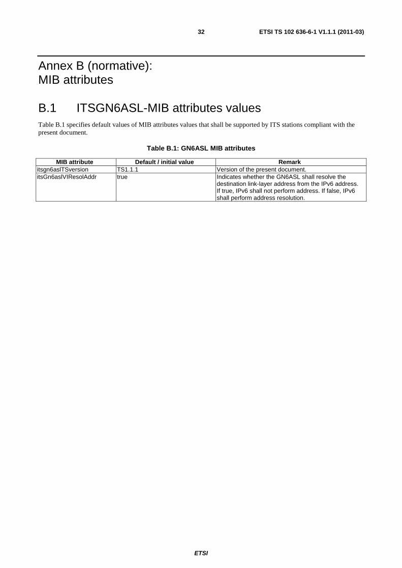
ETSI
ETSI TS 102 636-6-1 V1.1.1 (2011-03) 32
Annex B (normative): MIB attributes
B.1 ITSGN6ASL-MIB attributes values Table B.1 specifies default values of MIB attributes values that shall be supported by ITS stations compliant with the present document.
Table B.1: GN6ASL MIB attributes
MIB attribute Default / initial value Remark itsgn6aslTSversion TS1.1.1 Version of the present document. itsGn6aslVIResolAddr true Indicates whether the GN6ASL shall resolve the
destination link-layer address from the IPv6 address. If true, IPv6 shall not perform address. If false, IPv6 shall perform address resolution.
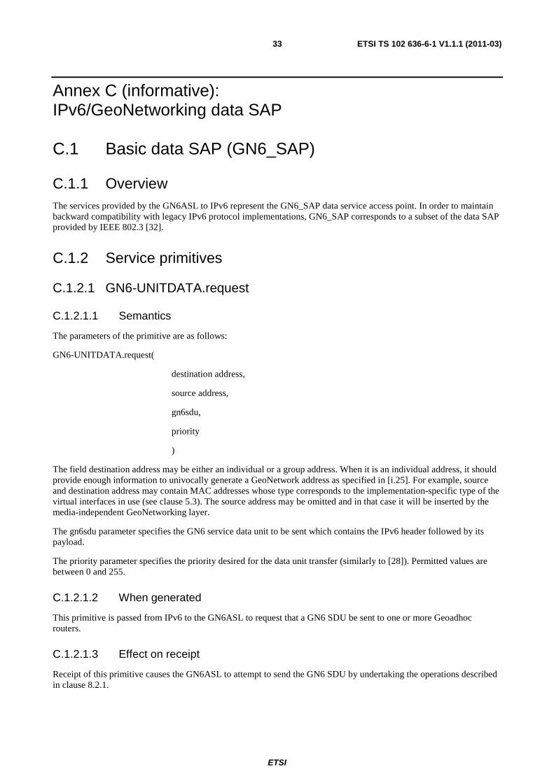
ETSI
ETSI TS 102 636-6-1 V1.1.1 (2011-03) 33
Annex C (informative): IPv6/GeoNetworking data SAP
C.1 Basic data SAP (GN6_SAP)
C.1.1 Overview The services provided by the GN6ASL to IPv6 represent the GN6_SAP data service access point. In order to maintain backward compatibility with legacy IPv6 protocol implementations, GN6_SAP corresponds to a subset of the data SAP provided by IEEE 802.3 [32].
C.1.2 Service primitives
C.1.2.1 GN6-UNITDATA.request
C.1.2.1.1 Semantics
The parameters of the primitive are as follows:
GN6-UNITDATA.request(
destination address,
source address,
gn6sdu,
priority
)
The field destination address may be either an individual or a group address. When it is an individual address, it should provide enough information to univocally generate a GeoNetwork address as specified in [i.25]. For example, source and destination address may contain MAC addresses whose type corresponds to the implementation-specific type of the virtual interfaces in use (see clause 5.3). The source address may be omitted and in that case it will be inserted by the media-independent GeoNetworking layer.
The gn6sdu parameter specifies the GN6 service data unit to be sent which contains the IPv6 header followed by its payload.
The priority parameter specifies the priority desired for the data unit transfer (similarly to [28]). Permitted values are between 0 and 255.
C.1.2.1.2 When generated
This primitive is passed from IPv6 to the GN6ASL to request that a GN6 SDU be sent to one or more Geoadhoc routers.
C.1.2.1.3 Effect on receipt
Receipt of this primitive causes the GN6ASL to attempt to send the GN6 SDU by undertaking the operations described in clause 8.2.1.
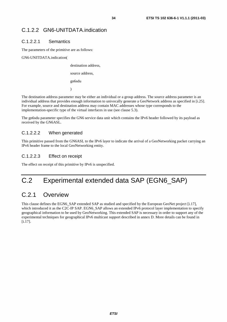
ETSI
ETSI TS 102 636-6-1 V1.1.1 (2011-03) 34
C.1.2.2 GN6-UNITDATA.indication
C.1.2.2.1 Semantics
The parameters of the primitive are as follows:
GN6-UNITDATA.indication(
destination address,
source address,
gn6sdu
)
The destination address parameter may be either an individual or a group address. The source address parameter is an individual address that provides enough information to univocally generate a GeoNetwork address as specified in [i.25]. For example, source and destination address may contain MAC addresses whose type corresponds to the implementation-specific type of the virtual interfaces in use (see clause 5.3).
The gn6sdu parameter specifies the GN6 service data unit which contains the IPv6 header followed by its payload as received by the GN6ASL.
C.1.2.2.2 When generated
This primitive passed from the GN6ASL to the IPv6 layer to indicate the arrival of a GeoNetworking packet carrying an IPv6 header frame to the local GeoNetworking entity.
C.1.2.2.3 Effect on receipt
The effect on receipt of this primitive by IPv6 is unspecified.
C.2 Experimental extended data SAP (EGN6_SAP)
C.2.1 Overview This clause defines the EGN6_SAP extended SAP as studied and specified by the European GeoNet project [i.17], which introduced it as the C2C-IP SAP. EGN6_SAP allows an extended IPv6 protocol layer implementation to specify geographical information to be used by GeoNetworking. This extended SAP is necessary in order to support any of the experimental techniques for geographical IPv6 multicast support described in annex D. More details can be found in [i.17].
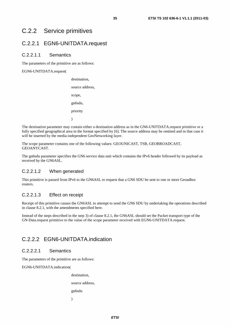
ETSI
ETSI TS 102 636-6-1 V1.1.1 (2011-03) 35
C.2.2 Service primitives
C.2.2.1 EGN6-UNITDATA.request
C.2.2.1.1 Semantics
The parameters of the primitive are as follows:
EGN6-UNITDATA.request(
destination,
source address,
scope,
gn6sdu,
priority
)
The destination parameter may contain either a destination address as in the GN6-UNITDATA.request primitive or a fully specified geographical area in the format specified by [6]. The source address may be omitted and in that case it will be inserted by the media-independent GeoNetworking layer.
The scope parameter contains one of the following values: GEOUNICAST, TSB, GEOBROADCAST, GEOANYCAST.
The gn6sdu parameter specifies the GN6 service data unit which contains the IPv6 header followed by its payload as received by the GN6ASL.
C.2.2.1.2 When generated
This primitive is passed from IPv6 to the GN6ASL to request that a GN6 SDU be sent to one or more Geoadhoc routers.
C.2.2.1.3 Effect on receipt
Receipt of this primitive causes the GN6ASL to attempt to send the GN6 SDU by undertaking the operations described in clause 8.2.1, with the amendments specified here.
Instead of the steps described in the step 3) of clause 8.2.1, the GN6ASL should set the Packet transport type of the GN-Data.request primitive to the value of the scope parameter received with EGN6-UNITDATA.request.
C.2.2.2 EGN6-UNITDATA.indication
C.2.2.2.1 Semantics
The parameters of the primitive are as follows:
EGN6-UNITDATA.indication(
destination,
source address,
gn6sdu
)

ETSI
ETSI TS 102 636-6-1 V1.1.1 (2011-03) 36
The destination address parameter may be either an individual or a group address. It may contain either a destination address as in the GN6-UNITDATA.request primitive or a GVL Area. The source address parameter is an individual address that provides enough information to univocally generate a GeoNetwork address as specified in [i.25].
The gn6sdu parameter specifies the GN6 service data unit which contains the IPv6 header followed by its payload as received by the GN6ASL.
C.2.2.2.2 When generated
This primitive passed from the GN6ASL to the IPv6 layer to indicate the arrival of a GeoNetworking packet carrying an IPv6 header frame to the local GeoNetworking entity.
C.2.2.2.3 Effect on receipt
The effect on receipt of this primitive by IPv6 is unspecified.
ETSI
ETSI TS 102 636-6-1 V1.1.1 (2011-03) 37
Annex D (informative): Geographic IPv6 multicast support (experimental)
D.1 Overview This annex describes experimental addressing schemes, studied and specified by the European GeoNet project [i.17], that aim at providing IPv6 applications with ways to specify target geographical areas as IPv6 group destination addresses. For example, this allows IPv6 hosts connected to an ITS station including a GeoAdhoc router to specify a desired geographical area as the target of IPv6 multicast traffic. It should be noted that achieving this functionality by making IPv6 geo-aware is outside the scope of the present document. However, the techniques studied by GeoNet for this specific purpose are overviewed in this annex as subject of further research and to facilitate further discussions.
The mechanisms specified in this annex have drawbacks which make them not suitable for immediate deployment. The recommended technique for the geographic distribution of IPv6 packets is described in clause 9.2.3.
The techniques described in this sub-clause were studied and specified by the European GeoNet project. More information can be found in [i.17].
The techniques described in this sub-clause require IPv6 to pass information regarding geographical areas to the GN6ASL. This is accomplished by the experimental EGN6_SAP specified in clause C.2.
D.2 Pre-defined geographical IPv6 multicast groups The GeoNet project implemented a simplified solution to allow the IPv6 layer to specify a target area as part of the IPv6 destination address. This solution consists of a pre-defined static table embedded in each ITS station running a GeoAdhoc router, containing the matching between pre-defined geographical areas and their corresponding multicast group IDs. Geographical areas are specified relatively to the Geoadhoc router position, e.g. a 1 000 m range circle around the Geoadhoc router.
Two main drawbacks affect this solution:
1) The IPv6 multicast groups corresponding to the pre-defined group IDs are moving targets due to the fact that the position is specified relatively to the Geoadhoc router position. This implies that the characterizing aspect of the multicast group changes over time, which conflicts with the assumptions of IPv6 multicasting and multicast group management.
2) The management of the table matching group IDs and geographical areas introduces further complexity. GeoNet adopted a statically defined table which limits the capability of nodes to choose the area. Dynamic management of the table would still require homogeneity across nodes and would therefore increase complexity.
D.3 Other studied mechanisms The GeoNet project studied alternative solutions to the one described in clause D.2, which are briefly recalled here. More information can be found in [i.17].
a) IPv6-in-IPv6 tunnel with areas encoded in the outer header and multicast groups in the inner header. With this solution, IPv6 nodes do not subscribe to relatively defined multicast groups but only to absolutely defined group. Therefore, the IPv6 host originating the packets need to know the absolute destination position. The granularity of the position encoding in the IPv6 group ID is deemed as too coarse. Additional overhead is caused by the IPv6-in-IPv6 tunnel.

ETSI
ETSI TS 102 636-6-1 V1.1.1 (2011-03) 38
b) Geographical area encoded in an IPv6 Hop-by-Hop option. This solution does not exploit IPv6 multicast group IDs as containers of the target group and therefore does not require IPv6 multicast group management. However, this solution introduces a new IPv6 option and therefore is not compatible with existing IPv6 protocol implementations.
c) IPv6-in-IPv6 tunnel with areas encoded in an IPv6 Hop-by-Hop option of the outer header. In this solution, the outer header is removed when the packet is received by the GeoAdhoc router. This solution reduces the overhead but introduces a new IPv6 option and therefore is not compatible with existing IPv6 protocol implementations.
d) Encoding of geographic information in group ID. In this solution, the destination area is encoded in the 112-bit IPv6 multicast group ID. If absolute positions are encoded, the limited space offers too coarse granularity. If relative positions are encoded, IPv6 multicast group membership management becomes ineffective.
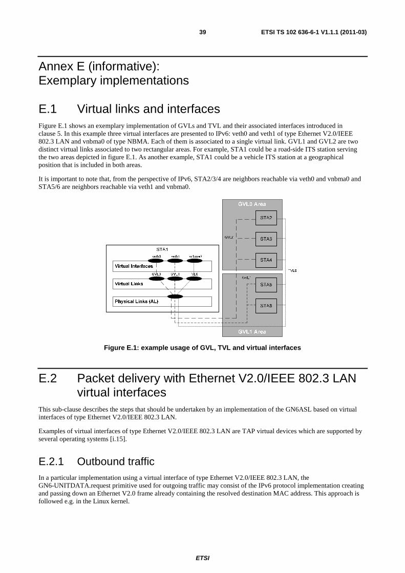
ETSI
ETSI TS 102 636-6-1 V1.1.1 (2011-03) 39
Annex E (informative): Exemplary implementations
E.1 Virtual links and interfaces Figure E.1 shows an exemplary implementation of GVLs and TVL and their associated interfaces introduced in clause 5. In this example three virtual interfaces are presented to IPv6: veth0 and veth1 of type Ethernet V2.0/IEEE 802.3 LAN and vnbma0 of type NBMA. Each of them is associated to a single virtual link. GVL1 and GVL2 are two distinct virtual links associated to two rectangular areas. For example, STA1 could be a road-side ITS station serving the two areas depicted in figure E.1. As another example, STA1 could be a vehicle ITS station at a geographical position that is included in both areas.
It is important to note that, from the perspective of IPv6, STA2/3/4 are neighbors reachable via veth0 and vnbma0 and STA5/6 are neighbors reachable via veth1 and vnbma0.
Figure E.1: example usage of GVL, TVL and virtual interfaces
E.2 Packet delivery with Ethernet V2.0/IEEE 802.3 LAN virtual interfaces
This sub-clause describes the steps that should be undertaken by an implementation of the GN6ASL based on virtual interfaces of type Ethernet V2.0/IEEE 802.3 LAN.
Examples of virtual interfaces of type Ethernet V2.0/IEEE 802.3 LAN are TAP virtual devices which are supported by several operating systems [i.15].
E.2.1 Outbound traffic In a particular implementation using a virtual interface of type Ethernet V2.0/IEEE 802.3 LAN, the GN6-UNITDATA.request primitive used for outgoing traffic may consist of the IPv6 protocol implementation creating and passing down an Ethernet V2.0 frame already containing the resolved destination MAC address. This approach is followed e.g. in the Linux kernel.
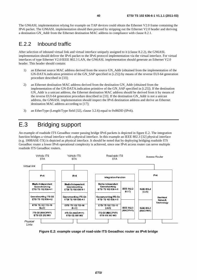
ETSI
ETSI TS 102 636-6-1 V1.1.1 (2011-03) 40
The GN6ASL implementation relying for example on TAP devices could obtain the Ethernet V2.0 frame containing the IPv6 packet. The GN6ASL implementation should then proceed by stripping out the Ethernet V2.0 header and deriving a destination GN_Addr from the Ethernet destination MAC address in compliance with clause 8.2.1.
E.2.2 Inbound traffic After selection of inbound virtual link and virtual interface uniquely assigned to it (clause 8.2.2), the GN6ASL implementation should deliver the IPv6 packet to the IPv6 protocol implementation via the virtual interface. For virtual interfaces of type Ethernet V2.0/IEEE 802.3 LAN, the GN6ASL implementation should generate an Ethernet V2.0 header. This header should contain:
1) an Ethernet source MAC address derived from the source GN_Addr (obtained from the implementation of the GN-DATA.indication primitive of the GN_SAP specified in [i.25]) by means of the reverse EUI-64 generation procedure described in [33];
2) an Ethernet destination MAC address derived from the destination GN_Addr (obtained from the implementation of the GN-DATA.indication primitive of the GN_SAP specified in [i.25]). If the destination GN_Addr is a unicast address, the Ethernet destination MAC address should be derived from it by means of the reverse EUI-64 generation procedure described in [33]. If the destination GN_Addr is not a unicast address, the GN6ASL implementation should inspect the IPv6 destination address and derive an Ethernet destination MAC address according to [17];
3) an EtherType (Length/Type field [32], clause 3.2.6) equal to 0x86DD (IPv6).
E.3 Bridging support An example of roadside ITS Geoadhoc router passing bridge IPv6 packets is depicted in figure E.2. The integration function bridges a virtual interface with a physical interface. In this example an IEEE 802.3 [32] physical interface (e.g. 100BASE-TX) is depicted as physical interface. It should be noted that by deploying bridging roadside ITS Geoadhoc router a lower IPv6 operational complexity is achieved, since one IPv6 access router can serve multiple roadside ITS Geoadhoc routers.
Figure E.2: example usage of road-side ITS Geoadhoc router as IPv6 bridge

ETSI
ETSI TS 102 636-6-1 V1.1.1 (2011-03) 41
E.4 GeoNet project implementations results The European GeoNet project [i.16] and [i.17] specified and implemented several mechanisms described in the present document, including the experimental approach described in clause D.2. A detailed report of the implementation and experimentation results is provided in [i.18].
ETSI
ETSI TS 102 636-6-1 V1.1.1 (2011-03) 42
Annex F (informative): Support for Network Mobility Basic Support
F.1 Purpose of this annex As pointed out in clause 1, extensions to NEMO BS [15] are outside the scope of the present document. However, the present document aims at providing full compatibility with NEMO BS, including pre-existing implementations. This annex briefly presents how NEMO BS can be utilized with GN6ASL.
F.2 Mode of operation via GN6ASL NEMO Basic Support [15] can be used in conjunction with GeoNetworking and the GN6ASL in order to provide session continuity and global reachability at a constant network prefix (the Mobile Network Prefix) for an entire moving network.
In particular, NEMO BS can be used on virtual interfaces associated to GVLs, since they provide link-local multicast support and SLAAC. Via a GVL, a NEMO BS Mobile Router can establish an IPv6-in-IPv6-in-GeoNetworking tunnel. In this configuration, access to an infrastructure network is provided by an ITS station including a Geoadhoc router and an access router (these functions may collapse or may also be separate, see clause 6.1). The Geoadhoc router represents the end point of the IPv6-in-GeoNetworking tunnel or, in other terms, the "GeoNetworking next hop". The access router represents the "IPv6 next hop" and the NEMO BS Home Agent the end point of the IPv6-in-IPv6 tunnel.
Via GVLs, a NEMO BS Mobile Router included in an ITS station receives IPv6 Router Advertisements and configures an address via SLAAC. Router Advertisements are the most commonly used mechanism for Movement Detection procedures in both NEMO BS and Mobile IPv6 [i.1]. In addition to the basic usage, GVLs can also be used to deploy sophisticated Movement Detection procedures, e.g. including make-before-break approaches by utilizing slightly overlapping geographical areas associated to GVLs and announced by road-side ITS stations.
More information about NEMO operation over GeoNetworking can also be found in [i.17] and [i.18], including experimental results.
F.3 Sub-optimal routing issues At the time of writing the present document, a standardized Route Optimization technique for NEMO BS has not been produced by the IETF. An ITS-specific effort [i.20] to provide specific requirements for automotive deployments of NEMO BS has been initiated and still needs to be completed. The issues related to the sub-optimal routing caused by the lack of Route Optimization techniques in NEMO BS are described in [i.20]. Deployments of the present document would extremely benefit from a standardized Route Optimization technique which specifically addressed the ITS requirements described in [i.20].
ETSI
ETSI TS 102 636-6-1 V1.1.1 (2011-03) 43
Annex G (informative): Security and privacy considerations
G.1 Purpose of this annex At the time of completing the present document, ETSI has not yet produced a GeoNetworking-specific privacy and security threat analysis, being [i.12] focused on ITS applications and not on specific protocols. It is recommended that such analysis is produced and that it includes possible attacks introduced by the GN6ASL. Aside from the threat analysis, security and privacy mechanisms to protect GeoNetworking have to be standardized in order to implement the services described in [i.13]. To facilitate this work, some preliminary considerations are provided in this annex.
G.2 Recommendations for security mechanisms It is expected that solutions providing authentication of GeoNetworking messages will strongly limit possible specific attacks to the GN6ASL. The most discussed approaches in the literature for authentication of GeoNetworking [i.23] [i.13] consist of asymmetric cryptography-based authentication of packets by means of specifically designed and administered digital certificates. Assuming that such a solution providing certificate-based authentication for GeoNetworking exists, IPv6 over GeoNetworking traffic can easily be secured without requiring any particular security extension to IPv6 and SEND [26].
A potential limitation of the applicability of SEND to the transmission of IPv6 over GeoNetworking is related to CGAs. Non-repudiation of messages requires the Certificate Authority to be able to match pseudonyms with real identity. This may limit the applicability of CGAs.
G.3 Recommendations for privacy-protecting deployment The usage of temporary GeoNetworking identifiers (GN_Addr) with the GN6ASL is explained in clause 11. By using these pseudonyms with an appropriate changing scheme, location privacy threats are strongly limited. However, these countermeasures might become ineffective as soon as other identifiers are transmitted in clear text that do not vary over time and might enable attackers to link different pseudonyms to the user's identity.
Consequently, it is highly recommended to not utilize manually generated IPv6 addresses on the interfaces assigned to GVLs and TVLs. Only automatically generated addresses should be used, so that a change in the GN_Addr will be reflected in a change in the IPv6 address (see clause 11.2).
Similarly, particular care should be put in avoiding that other information or identifiers that might be used to link pseudonyms are transmitted in clear-text. These include NEMO BS [15] signalling information like the Mobile Network Prefix and the Home Address.
ETSI
ETSI TS 102 636-6-1 V1.1.1 (2011-03) 44
Annex H (informative): Bibliography ETSI TS 102 636-5-1: "Intelligent Transport Systems (ITS); Vehicular Communications; GeoNetworking; Part 5: Transport Protocols; Sub-part 1: Basic Transport Protocol".
IETF draft-ietf-6man-ipv6-subnet-model-12 (April 2010): "IPv6 Subnet Model: the Relationship between Links and Subnet Prefixes" (work in progress).
ITU-T- Recommendation X.691:2008: "Information technology - ASN.1 encoding rules: Specification of Packed Encoding Rules (PER)".
IETF RFC 4213: "Basic Transition Mechanisms for IPv6 Hosts and Routers".
IETF RFC 4968: "Analysis of IPv6 Link Models for IEEE 802.16 Based Networks".
IETF RFC 4259: "A Framework for Transmission of IP Datagrams over MPEG-2 Networks".
IETF RFC 2009: "GPS-Based Addressing and Routing".
IETF RFC 3775: "Mobility Support in IPv6".

ETSI
ETSI TS 102 636-6-1 V1.1.1 (2011-03) 45
History
Document history
V1.1.1 March 2011 Publication