Embed Size (px)
Citation preview

ETSI TS 102 658 V1.2.1 (2009-09)
Technical Specification
Electromagnetic compatibility andRadio spectrum Matters (ERM);
Digital Private Mobile Radio (dPMR) usingFDMA with a channel spacing of 6,25 kHz
ETSI
ETSI TS 102 658 V1.2.1 (2009-09)2
Reference RTS/ERM-TGDMR-283
Keywords air interface, digital, FDMA, PMR, protocol, radio
ETSI
650 Route des Lucioles F-06921 Sophia Antipolis Cedex - FRANCE
Tel.: +33 4 92 94 42 00 Fax: +33 4 93 65 47 16
Siret N° 348 623 562 00017 - NAF 742 C
Association à but non lucratif enregistrée à la Sous-Préfecture de Grasse (06) N° 7803/88
Important notice
Individual copies of the present document can be downloaded from: http://www.etsi.org
The present document may be made available in more than one electronic version or in print. In any case of existing or perceived difference in contents between such versions, the reference version is the Portable Document Format (PDF).
In case of dispute, the reference shall be the printing on ETSI printers of the PDF version kept on a specific network drive within ETSI Secretariat.
Users of the present document should be aware that the document may be subject to revision or change of status. Information on the current status of this and other ETSI documents is available at
http://portal.etsi.org/tb/status/status.asp
If you find errors in the present document, please send your comment to one of the following services: http://portal.etsi.org/chaircor/ETSI_support.asp
Copyright Notification
No part may be reproduced except as authorized by written permission. The copyright and the foregoing restriction extend to reproduction in all media.
© European Telecommunications Standards Institute 2009.
All rights reserved.
DECTTM, PLUGTESTSTM, UMTSTM, TIPHONTM, the TIPHON logo and the ETSI logo are Trade Marks of ETSI registered for the benefit of its Members.
3GPPTM is a Trade Mark of ETSI registered for the benefit of its Members and of the 3GPP Organizational Partners. LTE™ is a Trade Mark of ETSI currently being registered
for the benefit of its Members and of the 3GPP Organizational Partners. GSM® and the GSM logo are Trade Marks registered and owned by the GSM Association.

ETSI
ETSI TS 102 658 V1.2.1 (2009-09)3
Contents
Intellectual Property Rights .............................................................................................................................. 11
Foreword ........................................................................................................................................................... 11
1 Scope ...................................................................................................................................................... 12
2 References .............................................................................................................................................. 12
2.1 Normative references ....................................................................................................................................... 12
2.2 Informative references ...................................................................................................................................... 13
3 Definitions, symbols and abbreviations ................................................................................................. 13
3.1 Definitions ........................................................................................................................................................ 13
3.2 Symbols ............................................................................................................................................................ 15
3.3 Abbreviations ................................................................................................................................................... 15
4 Overview ................................................................................................................................................ 16
4.1 Protocol architecture......................................................................................................................................... 17
4.1.1 Air Interface Physical Layer (layer 1)......................................................................................................... 17
4.1.2 Air Interface Data Link Layer (layer 2) ...................................................................................................... 18
4.1.3 Air Interface Call Control Layer (layer 3) .................................................................................................. 18
4.1.4 Architectural Configurations ...................................................................................................................... 18
4.1.4.1 Peer-to-Peer Direct Network (Mode 1) ................................................................................................. 18
4.1.4.2 Centralized Repeater Network (Mode 2) .............................................................................................. 19
4.1.4.3 Managed Centralized Repeater Network (Mode 3) ............................................................................... 19
4.1.4.3.1 Beacon Channel ............................................................................................................................... 19
4.1.4.3.2 Traffic Channel ................................................................................................................................ 20
4.1.5 Channel Access Mechanisms ...................................................................................................................... 20
4.1.5.1 Random Access (Mode 1, Mode 2) ....................................................................................................... 20
4.1.5.2 Regulated Random Access (Mode 3) .................................................................................................... 20
4.1.5.3 Polling ................................................................................................................................................... 20
4.1.5.4 Beacon Signal ....................................................................................................................................... 21
4.2 FDMA Structure ............................................................................................................................................... 21
4.2.1 Overview of transmission and burst structure ............................................................................................. 21
4.2.2 Transmission format ................................................................................................................................... 21
4.2.2.1 Traffic Channel Message Frame ........................................................................................................... 21
4.2.2.2 Traffic Channel Payload Frame ............................................................................................................ 22
4.2.2.2.1 Traffic Channel Superframe ............................................................................................................ 22
4.2.2.2 Traffic Channel Packet Data Header Frame .......................................................................................... 22
4.2.2.3 Traffic Channel End Frame ................................................................................................................... 23
4.2.2.4 Beacon SYScast Frame ......................................................................................................................... 23
4.2.3 Transmission sequences .............................................................................................................................. 23
4.2.3.1 Traffic Channel Voice or data payload item transmission .................................................................... 23
4.2.3.2 Traffic Channel Call set up, service request, etc. .................................................................................. 24
4.2.3.3 Traffic Channel Acknowledgement ...................................................................................................... 24
4.2.3.4 Traffic Channel Status request acknowledgements ............................................................................... 24
4.2.3.5 Traffic Channel Disconnection ............................................................................................................. 24
4.2.3.6 Traffic Channel Preservation Message.................................................................................................. 25
4.2.3.7 Mode 3 Beacon Channel ....................................................................................................................... 25
4.2.3.8 Mode 1 Call Exchange .......................................................................................................................... 25
4.2.3.8.1 Mode 1 Voice Call ........................................................................................................................... 25
4.2.3.8.2 Mode 1 Data Call............................................................................................................................. 26
4.2.3.9 Mode 2 Call Exchange .......................................................................................................................... 27
4.2.3.10 Co-channel BS networks ....................................................................................................................... 28
4.2.3.11 Mode 3 Operation ................................................................................................................................. 29
4.3 Addressing ........................................................................................................................................................ 31
4.4 Unified Data Transport Mechanism ................................................................................................................. 31
4.5 Complementary Data ........................................................................................................................................ 31
4.5.1 Support for Voice and Data call services .................................................................................................... 32
4.5.2 Transport of complementary data for MS control ....................................................................................... 32
ETSI
ETSI TS 102 658 V1.2.1 (2009-09)4
5 Frame coding .......................................................................................................................................... 32
5.1 Payload Frame [T] ............................................................................................................................................ 34
5.2 Message_Frame [BT] ....................................................................................................................................... 34
5.2.1 Communications_Start Header [T] ............................................................................................................. 35
5.2.1.1 Concatenated Superframe to a Communications_Start Header [T] ...................................................... 35
5.2.2 Connection_Request Header [T] ................................................................................................................. 37
5.2.2.1 Called Party Check [T] .......................................................................................................................... 37
5.2.2.2 Repeat Last Ack (RLA) [T] .................................................................................................................. 38
5.2.2.3 Status Delivery Header message [T] ..................................................................................................... 38
5.2.2.4 Call Diversion [T] ................................................................................................................................. 39
5.2.3 Disconnect_Request Header [T] ................................................................................................................. 39
5.2.4 T_ACK B_ACK Message [T] .................................................................................................................... 39
5.2.4.1 Message Information for acknowledgements ........................................................................................ 40
5.2.5 Maintenance_Message [T] .......................................................................................................................... 40
5.2.5.1 Idle Message [T] ................................................................................................................................... 41
5.2.5.2 Preservation message ............................................................................................................................ 41
5.2.5.3 Guard_Message [T] ............................................................................................................................... 42
5.2.6 System_Request Header [T] ....................................................................................................................... 42
5.2.7 ACK header response to a System Request [T] .......................................................................................... 43
5.2.8 System Delivery Header [T] ....................................................................................................................... 43
5.2.9 Status Polling Response Message [T] ......................................................................................................... 43
5.2.10 Status Polling Request Message [T] ........................................................................................................... 44
5.2.11 BS_Command header(U) and response(D) [T]........................................................................................... 44
5.2.12 BS_Access header(U) and response(D) [T] ................................................................................................ 44
5.2.13 Broadcast Messages [B] [T]........................................................................................................................ 45
5.2.13.1 Broadcast Aloha Message [B] ............................................................................................................... 45
5.2.13.2 Broadcast Announcements [B].............................................................................................................. 46
5.2.13.2.1 Broadcast Announcement - Call Timers [B] ................................................................................... 47
5.2.13.2.2 Broadcast Announcement - Vote Now [B] ...................................................................................... 47
5.2.13.2.3 Broadcast Announcement - Mass Registration [B] ......................................................................... 48
5.2.13.2.4 Broadcast Announcement - Real Time [B]...................................................................................... 48
5.2.13.3 Move Channel Broadcast [BT] ............................................................................................................. 49
5.2.13.4 Goto Channel Broadcast [BT] ............................................................................................................... 49
5.2.13.4.1 Appended_Data to the Goto Channel) ............................................................................................. 50
5.2.13.5 Ambience Listening [T] ........................................................................................................................ 50
5.2.14 AHOY / Random Access Request Message [B] ......................................................................................... 51
5.2.14.1 B_AHOY Message Downlink [B] ........................................................................................................ 51
5.2.14.2 Random Access Request Uplink [B] ..................................................................................................... 53
5.2.15 UDT Header messages [B] ......................................................................................................................... 54
5.3 End_Frame ....................................................................................................................................................... 55
5.4 Packet Data Header [T] .................................................................................................................................... 56
5.5 Field Descriptions............................................................................................................................................. 56
5.5.1 Active ACTIVE [B] .................................................................................................................................... 57
5.5.2 Appended_ Data [BT] ................................................................................................................................. 57
5.5.3 ARQ [T] ...................................................................................................................................................... 57
5.5.4 Backoff [B] ................................................................................................................................................. 58
5.5.5 Call Timers [BT] ......................................................................................................................................... 58
5.5.6 Communication format [BT] ...................................................................................................................... 59
5.5.7 Communication Mode [BT] ........................................................................................................................ 59
5.5.8 COMP [B] ................................................................................................................................................... 59
5.5.9 Continuation_Flag [T] ................................................................................................................................ 60
5.5.10 Day of Week (DAYSOF_WEEK) [B] ........................................................................................................ 60
5.4.11 Digits [BT] .................................................................................................................................................. 60
5.5.12 Emergency Priority [BT] ............................................................................................................................ 61
5.5.13 End_Type [T] .............................................................................................................................................. 61
5.5.14 Frame numbering [T] .................................................................................................................................. 61
5.5.15 Frequency Definitions FR, FT, SEP, BAND [BT] ..................................................................................... 62
5.5.16 Guard_Kind [T] .......................................................................................................................................... 62
5.5.17 Long [B] ..................................................................................................................................................... 63
5.5.18 Mask [B] ..................................................................................................................................................... 63
5.5.19 Message Information [BT] .......................................................................................................................... 63
5.5.19.1 Message Information for Powersave [T] ............................................................................................... 64

ETSI
ETSI TS 102 658 V1.2.1 (2009-09)5
5.5.19.2 Message Information for Types 1 and 2 data [T] .................................................................................. 64
5.5.19.3 Message Information for Type 3 (packet) data [T] ............................................................................... 65
5.5.19.4 Message Information for system transactions [T] ................................................................................. 65
5.5.19.5 Message Information for B_ACK T_ACK acknowledgements [BT] ................................................... 66
5.5.19.6 Message Information for Broadcast headers [BT] ................................................................................ 66
5.5.19.7 Message Information for BS Command headers [T] ............................................................................ 66
5.5.19.8 Message Information for additional services [B] .................................................................................. 67
5.5.20 Message_Type [BT] ................................................................................................................................... 68
5.5.21 Month B_MONTH ..................................................................................................................................... 68
5.5.22 NRand_Wait [B] ......................................................................................................................................... 68
5.5.23 Preservation_Message PM [T] .................................................................................................................... 69
5.5.24 POL_FMT [BT] .......................................................................................................................................... 69
5.5.25 Reason [BT] ................................................................................................................................................ 69
5.5.26 Reg [B] ....................................................................................................................................................... 72
5.5.27 Reserved [BT] ............................................................................................................................................. 72
5.5.28 Service Function [B] ................................................................................................................................... 72
5.5.29 SLD format [T] ........................................................................................................................................... 73
5.5.29.1 SLow Data in the voice superframe ...................................................................................................... 73
5.5.29.2 SLow Data field use with Type 1 or 2 data ........................................................................................... 73
5.5.30 Status [T] .................................................................................................................................................... 74
5.5.31 SYMB [BT] ................................................................................................................................................ 74
5.5.32 SYScast [B] ................................................................................................................................................ 74
5.5.32.1 SYScast1 [B] ......................................................................................................................................... 74
5.5.32.2 SYScast2 or SYScast3 [B] .................................................................................................................... 74
5.5.32.2.1 SYScast2 or SYScast3 Call Timer MS to MS [B] ........................................................................... 75
5.5.32.2.2 Call Timer for line connected calls and packet data [B] .................................................................. 75
5.5.32.2.3 SYScast2 or SYScast3 Real Time [B] ............................................................................................. 75
5.5.32.2.4 SYScast2 or SYScast3 Common Frame Counter [B] ...................................................................... 76
5.5.33 System Identity Code [B] ........................................................................................................................... 76
5.5.34 Tx_Wait [T] ................................................................................................................................................ 76
5.5.35 UAD [BT] ................................................................................................................................................... 77
5.5.36 UDT_Format [BT] ...................................................................................................................................... 77
5.5.37 Version [BT] ............................................................................................................................................... 77
5.5.38 Vote Now Advice Parameters [B] .............................................................................................................. 77
5.5.39 Withdrawn W [B] ....................................................................................................................................... 78
5.6 Appended_Data Messages [BT] ....................................................................................................................... 78
5.6.1 Appended_Datan MS ID Format ................................................................................................................ 78
5.6.2 Appended_Data Binary Format .................................................................................................................. 78
5.6.3 Appended_Data BCD Format ..................................................................................................................... 79
5.6.4 Appended_Data (ISO 7 bit character set Format) ....................................................................................... 79
5.6.5 Appended_Data (ISO 8 bit character set format) ........................................................................................ 80
5.6.6 Appended_Data NMEA (EN 61162-1) format ........................................................................................... 80
5.6.7 Appended_Data IPV4 format ..................................................................................................................... 81
5.6.8 Appended_Data IPV6 format ..................................................................................................................... 81
5.6.9 Appended_Data Filler ................................................................................................................................. 82
6 Synchronization ...................................................................................................................................... 82
6.1 Frame synchronization ..................................................................................................................................... 82
6.1.1 FS1 .............................................................................................................................................................. 82
6.1.2 FS2 .............................................................................................................................................................. 82
6.1.3 FS3 .............................................................................................................................................................. 82
6.1.4 FS4 .............................................................................................................................................................. 83
6.1.5 Colour Code ................................................................................................................................................ 83
6.1.6 Preamble ..................................................................................................................................................... 85
7 Interleaving and FEC coding .................................................................................................................. 85
7.1 CRC addition .................................................................................................................................................... 85
7.2 Hamming code ................................................................................................................................................. 85
7.3 Scrambling ....................................................................................................................................................... 86
7.4 Interleaving....................................................................................................................................................... 86
7.5 FEC coding of CCH (superframe) .................................................................................................................... 87
7.6 FEC coding of MI (message info') and HI (header info') ................................................................................. 87

ETSI
ETSI TS 102 658 V1.2.1 (2009-09)6
7.7 FEC coding of END information ..................................................................................................................... 87
8 Bearer services, tele-services and supplementary services .................................................................... 88
8.2 Call types .......................................................................................................................................................... 89
8.2.1 Individual call ............................................................................................................................................. 89
8.2.2 Group call ................................................................................................................................................... 89
8.3 Addressing ........................................................................................................................................................ 90
8.4 Colour Codes .................................................................................................................................................... 90
8.5 Messages .......................................................................................................................................................... 90
8.5.1 Downlink Traffic Channel messages .......................................................................................................... 90
8.5.2 Uplink Traffic Channel messages ............................................................................................................... 91
8.5.3 Downlink Beacon messages ....................................................................................................................... 91
8.5.4 Uplink Beacon messages ............................................................................................................................ 92
9 Packet data .............................................................................................................................................. 92
9.1 Format .............................................................................................................................................................. 92
9.2 Receiving party ................................................................................................................................................ 93
9.3 Packet frame coding ......................................................................................................................................... 94
9.4 Data frame size ................................................................................................................................................. 94
9.5 Valid data length .............................................................................................................................................. 95
9.6 Data checksum ................................................................................................................................................. 95
9.7 Standard Packet Exchange Format ................................................................................................................... 96
10 Call Procedures ...................................................................................................................................... 97
10.1 Call procedures for Mode 1 .............................................................................................................................. 98
10.1.1 Common procedures for Voice and Data calls ........................................................................................... 98
10.1.1.1 Call set up.............................................................................................................................................. 98
10.1.2 Voice calls ................................................................................................................................................ 100
10.1.2.1 Voice Call in progress ......................................................................................................................... 100
10.1.2.2 Voice Call with Slow Data .................................................................................................................. 101
10.1.2.3 Voice Call with Attached Data............................................................................................................ 101
10.1.2.4 Voice Call Termination ....................................................................................................................... 101
10.1.3 Data Calls.................................................................................................................................................. 101
10.1.3.1 T1 and T2 Data calls ........................................................................................................................... 101
10.1.3.2 T3 (Packet) Data Calls ........................................................................................................................ 103
10.1.3.3 Individual Status polling ..................................................................................................................... 105
10.1.3.4 Short Data Delivery............................................................................................................................. 107
10.1.3 Traffic Channel Powersave ....................................................................................................................... 108
10.1.3.1 Transmitted format .............................................................................................................................. 109
10.1.3.2 Receive format .................................................................................................................................... 109
10.2 Call procedures for Mode 2 ............................................................................................................................ 110
10.2.1 MS to MS Call set up. ............................................................................................................................... 110
10.2.2 MS to MS Voice Calls .............................................................................................................................. 111
10.2.3 Data Calls.................................................................................................................................................. 112
10.2.3.1 T1 and T2 Data Calls .......................................................................................................................... 112
10.2.3.2 T3 (Packet) Data Calls ........................................................................................................................ 113
10.2.3.3 MS to MS Status request and responses .............................................................................................. 113
10.2.3.4 MS to MS Short Data .......................................................................................................................... 113
10.2.4 MS Mode 2 Call Diversion ....................................................................................................................... 114
10.2.4.1 Setting the diversion ............................................................................................................................ 115
10.2.4.2 Cancelling the diversion ...................................................................................................................... 115
10.2.5 Mode 2 Connection to line connected destinations ................................................................................... 115
10.2.5.1 Voice Call Connection_Request message ........................................................................................... 118
10.2.5.2 Call Matrix for calls to line connected destinations ............................................................................ 118
10.2.6 Mode 2 calls from line connected sources ................................................................................................ 119
10.2.6.1 Call Matrix for calls from line connected destinations ....................................................................... 119
10.2.7 Co-channel repeater networks................................................................................................................... 119
10.2.7.1 MS originated repeater polling ............................................................................................................ 119
10.2.7.1.1 Description of the messages .......................................................................................................... 121
10.2.7.2 BS originated repeater polling............................................................................................................. 121
10.2.7.2.1 Description of the messages .......................................................................................................... 122
10.2.7.3 Access and Response timing ............................................................................................................... 123
10.3 Call Procedures for Mode 3 ............................................................................................................................ 123

ETSI
ETSI TS 102 658 V1.2.1 (2009-09)7
10.3.1 Mode 3 UDT Mechanism ......................................................................................................................... 124
10.3.1.1 Format of the Appended_Data ............................................................................................................ 125
10.3.1.2 UDT Structure ..................................................................................................................................... 126
10.3.1.2.1 UDT Content for Services Carried on the Downlink channel ....................................................... 126
10.3.1.2.2 UDT Mechanism for the Uplink channel ...................................................................................... 127
10.3.1.3 Single Part and Multi-part call set-up ................................................................................................. 127
10.3.1.4 MS behaviour to B_AHOY messages ................................................................................................. 127
10.3.2 Mode 3 call examples ............................................................................................................................... 128
10.3.2.1 An individual voice call example ........................................................................................................ 128
10.3.2.2 A talkgroup call example .................................................................................................................... 129
10.3.2.3 Example Short Data call example ....................................................................................................... 129
10.3.2.4 Example Call to PABX/PSTN example .............................................................................................. 130
10.3.2.5 Call from the PABX/PSTN example .................................................................................................. 130
10.3.2.6 Example - transport of complementary data ....................................................................................... 131
10.3.2.7 Example - transport of complementary data and an extended address. ............................................... 131
10.3.3 Detailed Call procedures ........................................................................................................................... 132
10.3.3.1 Procedures common to Voice calls and Data Calls ............................................................................. 132
10.3.3.1.1 Availability of requesting MS ....................................................................................................... 132
10.3.3.1.2 Call Cancellation ................................................................................................................................. 132
10.3.3.1.3 Acknowledgements sent to calling MS ............................................................................................... 133
10.3.3.1.4 Maintenance of call progress waiting timers ....................................................................................... 133
10.3.3.1.5 Traffic Channel Assignment ............................................................................................................... 134
10.3.4 Voice Call Procedures .............................................................................................................................. 134
10.3.4.1 Voice Call Procedures for the BS ....................................................................................................... 135
10.3.4.1.1 BS Response to single-part voice call set-up ................................................................................. 135
10.3.4.1.2 BS Response to multi-part voice call set-up .................................................................................. 135
10.3.4.1.3 Acknowledgements sent on the BS to the calling MS (voice) ....................................................... 136
10.3.4.1.4 Voice Radio Check ........................................................................................................................ 136
10.3.4.1.5 Availability Check for Voice Calls connected through Gateways ................................................ 136
10.3.4.2 Voice Call Procedures for MS ............................................................................................................ 136
10.3.4.2.1 Initiating a single-part voice call service ....................................................................................... 137
10.3.4.2.2 Response to the single-part individual voice service request ........................................................ 137
10.3.4.2.3 Response to the multi-part voice service request ........................................................................... 138
10.3.4.2.4 Acknowledgements received by the calling MS (voice) ............................................................... 138
10.3.4.2.5 Availability Check to the called MS (voice) ................................................................................. 139
10.3.4.2.6 Traffic Channel Allocation ............................................................................................................ 139
10.3.4.3 Procedures for the Voice Traffic Channel ..................................................................................... 139
10.3.4.3.1 BS Procedures for the Voice Traffic Channel ............................................................................... 139
10.3.4.3.2 MS Procedures for the Voice Traffic Channel .............................................................................. 140
10.3.5. Data Call Procedures ................................................................................................................................ 142
10.3.5.1 Data Call Procedures for the BS ......................................................................................................... 142
10.3.5.1.1 BS Response to single-part data call set-up ................................................................................... 142
10.3.5.1.2 BS Response to multi-part data call set-up .................................................................................... 143
10.3.5.1.3 Acknowledgements sent on the BS to the calling MS (data) ......................................................... 143
10.3.5.1.4 Radio Check for Data .................................................................................................................... 143
10.3.5.1.5 Availability Check for Data Calls connected through Gateways .................................................. 144
10.3.5.2 Data Call Procedures for MS .............................................................................................................. 144
10.3.5.2.1 Initiating a single-part data call service ......................................................................................... 145
10.3.5.2.2 Response to the single-part data call service request ..................................................................... 145
10.3.5.2.3 Response to the multi-part data service request ............................................................................. 145
10.3.5.2.4 Acknowledgements received by the calling MS (data) ................................................................. 145
10.3.5.2.5 Availability Check to the called MS (data) ................................................................................... 146
10.3.5.2.6 Traffic Channel Allocation ............................................................................................................ 146
10.3.5.3 Procedures for the Data Traffic Channel ............................................................................................. 146
10.3.5.3.1 BS Procedures for the Data Traffic Channel ................................................................................. 146
10.3.5.3.2 MS Procedures for the Data Traffic Channel ................................................................................ 147
10.3.5.4 Short Data Message Procedure ........................................................................................................... 148
10.3.5.4.1 Short Data Procedures for the BS .................................................................................................. 149
10.3.5.4.2 Short Data Message procedures for MS ........................................................................................ 151
10.3.5.4.3 Initiating a Short Data Message service ........................................................................................ 152
10.3.5.4.4 Response to a random access short data message .......................................................................... 152
10.3.5.4.5 Acknowledgements received by the calling MS ............................................................................ 152

ETSI
ETSI TS 102 658 V1.2.1 (2009-09)8
10.3.5.4.6 Timeout waiting for further signalling .......................................................................................... 152
10.3.5.4.7 MS receiving a short data message ................................................................................................ 152
10.3.5.5 Short Data Polling Service .................................................................................................................. 153
10.3.5.5.1 Short Data Polling Procedures for the BS ..................................................................................... 154
10.3.5.5.2 Short Data Polling Message procedures for MS ............................................................................ 155
10.3.5.5.3 Initiating a Short Data Polling service ........................................................................................... 155
10.3.5.5.4 Response to a random access short data polling message ............................................................. 155
10.3.5.5.5 Final Acknowledgement transmitted by the calling MS ................................................................ 156
10.3.5.5.6 Timeout waiting for further signalling .......................................................................................... 156
10.3.5.5.7 MS receiving a B_AHOY poll for a short polling message .......................................................... 156
10.3.5.6 Status Call Service .............................................................................................................................. 156
10.3.5.6.1 Status Service Delivery Procedure ................................................................................................ 156
10.3.5.7 Call Diversion ..................................................................................................................................... 159
10.3.5.7.1 Call Diversion Service ................................................................................................................... 159
10.3.5.7.2 Call set-up to an MS that has a Diverted address .......................................................................... 162
10.3.5.8 MS Stun/Revive Procedures................................................................................................................ 162
10.3.5.8.1 MS Stun/Revive without authentication ........................................................................................ 162
11 Channel coding process ........................................................................................................................ 163
11.1 Voice superframe ........................................................................................................................................... 163
11.5 Messages ........................................................................................................................................................ 173
11.7 SYScast Frames .............................................................................................................................................. 176
12 Channel access ..................................................................................................................................... 176
12.1 Channel access for Mode 1 [M1] ................................................................................................................... 177
12.1.1 Listen Before Transmit (LBT) [M1] ......................................................................................................... 177
12.1.2 Hang time messages and timers [M1] ....................................................................................................... 178
12.1.2.1 Definition [M1] ................................................................................................................................... 178
12.1.2.2 Action by receiving stations [M1] ....................................................................................................... 178
12.1.2.3 Call duration timers [M1] .................................................................................................................... 178
12.1.2.3.1 Item Duration Timer for Voice Calls [M1] ................................................................................... 178
12.1.2.3.2 Item Duration Timer for Data Calls [M1] ..................................................................................... 178
12.1.3 Transmit admit criteria [M1] .................................................................................................................... 178
12.1.3.1 Channel "Politeness" [M1] .................................................................................................................. 178
12.1.3.2 General Timing [M1] .......................................................................................................................... 179
12.1.3.3 Transmission re-tries [M1] .................................................................................................................. 179
12.1.3.4 Emergency channel access procedures [M1] ...................................................................................... 179
12.1.3.4.1 Emergency Break-in requests [M1] ............................................................................................... 179
12.2 Channel access for Mode 2 [M2] ................................................................................................................... 180
12.2.1 Listen Before Transmit (LBT) [M2] ......................................................................................................... 180
12.2.2 Hang time messages and timers [M2] ....................................................................................................... 181
12.2.2.1 Definition [M2] ................................................................................................................................... 181
12.2.2.2 Action by receiving stations [M2] ....................................................................................................... 181
12.2.2.3 Call duration timers [M2] .................................................................................................................... 182
12.2.2.3.1 Item Duration Timer for Voice Calls [M2] ................................................................................... 182
12.2.2.3.2 Item Duration Timer for Data Calls [M2] ..................................................................................... 182
12.2.3 Transmit admit criteria [M2] .................................................................................................................... 182
12.2.3.1 Channel "Politeness" [M2] .................................................................................................................. 182
12.2.3.2 General Timing [M2] .......................................................................................................................... 182
12.2.3.3 Transmission re-tries [M2] .................................................................................................................. 183
12.2.3.4 Emergency channel access procedures [M2] ...................................................................................... 183
12.2.3.4.1 Emergency Break-in requests [M2] ............................................................................................... 184
12.3 Channel access for Mode 3 [M3] .............................................................................................................. 184
12.3.1 Mode 3 Channel Structure ........................................................................................................................ 184
12.3.2 Introduction to the Beacon Structure ........................................................................................................ 185
12.3.2.1 Beacon Timing .................................................................................................................................... 185
12.3.3 Network architecture................................................................................................................................. 186
12.3.3.1 Network functions ............................................................................................................................... 186
12.3.3.1.1 Establishing service ....................................................................................................................... 186
12.3.3.1.2 Network Identifier ......................................................................................................................... 186
12.3.3.2 MS Location by Registration .............................................................................................................. 186
12.3.4 Trunking methods ..................................................................................................................................... 187
ETSI
ETSI TS 102 658 V1.2.1 (2009-09)9
12.3.5 Beacon Channel Formats .......................................................................................................................... 187
12.3.5.1 Use of the SYScast Frames ................................................................................................................. 188
12.3.5.1.1 SYC1 SYScast Frame .................................................................................................................... 188
12.3.5.1.2 SYC2 or SYSC3 SYScast Frame .................................................................................................. 188
12.3.5.2 Beacon Frame Structure ...................................................................................................................... 188
12.3.5.2.1 Frames on the Beacon downlink channel ...................................................................................... 188
12.3.5.2.2 Frames on the Beacon uplink channel ........................................................................................... 189
12.3.6 Channel Access for a Beacon Channel ..................................................................................................... 189
12.3.6.1 Basic Structure .................................................................................................................................... 189
12.3.6.1.1 Channel Structure .......................................................................................................................... 189
12.3.6.1.2 Physical Channel Addressing ........................................................................................................ 190
12.3.6.1.3 Sub-Division of the MS population ............................................................................................... 190
12.3.7 Random Access Procedures ...................................................................................................................... 191
12.3.7.1 The Random Access Principle ............................................................................................................ 191
12.3.7.1.1 Random Access Control ................................................................................................................ 191
12.3.7.1.2 Action after receiving an acknowledgement ................................................................................. 196
12.3.7.1.3 MS Arriving on a Beacon Channel ................................................................................................ 197
12.3.8 Beacon Channel Acquisition and Retention ............................................................................................. 197
12.3.8.1 MS Parameter Volatility ..................................................................................................................... 198
12.3.8.2 Beacon Channel Acquisition Procedures ............................................................................................ 198
12.3.8.2.1 Entry into Beacon Acquisition Procedures .................................................................................... 199
12.3.8.2.2 Identifying a Candidate Beacon Channel ...................................................................................... 199
12.3.8.2.3 Confirmation - Monitoring the BS downlink channel signal quality ............................................. 202
12.3.8.3 MS Leaving a Beacon Channel ........................................................................................................... 202
12.3.8.3.1 Leaving a Beacon Channel Whilst Waiting for Signalling ............................................................ 203
12.3.8.4 Registration, Power Save, and Authentication Procedures ................................................................. 203
12.3.8.4.1 General .......................................................................................................................................... 203
12.3.8.4.2 Registration Procedures ................................................................................................................. 205
12.3.9 Mass re-registration .................................................................................................................................. 207
12.3.9.1 Procedure for MS on receipt of Mass Re-registration Broadcast ........................................................ 207
12.3.9.2 De-registration .................................................................................................................................... 208
12.3.10 Beacon Power Save .................................................................................................................................. 208
12.3.10.1 Overview ............................................................................................................................................. 208
12.3.10.2 Power Save Procedures ....................................................................................................................... 209
12.3.10.2.1 Basic Power Save Procedures ........................................................................................................ 209
12.3.11 Electronic Serial Number Check Procedures ............................................................................................ 211
12.3.11.1 ESN Procedures for the BS to authenticate an MS ............................................................................. 212
12.3.11.2 ESN Procedures for the MS ................................................................................................................ 212
13 Timers, constants levels and addresses ................................................................................................ 213
13.1 Timers ............................................................................................................................................................ 213
13.2 Constants ........................................................................................................................................................ 214
13.3 Levels ............................................................................................................................................................. 214
13.4 Gateways/Identifiers ....................................................................................................................................... 215
13.5 Message Matrix's ............................................................................................................................................ 216
14 Physical Layer ...................................................................................................................................... 217
14.1 General parameters ......................................................................................................................................... 217
14.1.1 Frequency range ........................................................................................................................................ 217
14.1.2 RF carrier bandwidth ................................................................................................................................ 217
14.1.3 Transmit frequency error .......................................................................................................................... 217
14.1.4 Time base clock drift error ........................................................................................................................ 217
14.2 Modulation ..................................................................................................................................................... 217
14.2.1 Symbols .................................................................................................................................................... 217
14.2.2 4FSK generation ....................................................................................................................................... 217
14.2.2.1 Deviation index ................................................................................................................................... 217
14.2.2.2 Square root raised cosine filter ............................................................................................................ 218
14.2.2.3 4FSK Modulator ................................................................................................................................. 219
Annex A (normative): Standard User Interface .............................................................................. 220
A.1 Numbering and dialling plan ................................................................................................................ 220
A.1.1 Introduction to the numbering and dialling plan ............................................................................................ 220

ETSI
ETSI TS 102 658 V1.2.1 (2009-09)10
A.1.2 Subscriber mapping ........................................................................................................................................ 221
A.1.2.1 User Interface - Air Interface .................................................................................................................... 221
A.1.2.1.1 Mapping for MS address space ........................................................................................................... 222
A.1.2.1.1.1 The concept of the wildcard character ........................................................................................... 222
A.1.2.1.1.2 The concept of stored parameters .................................................................................................. 222
A.1.2.1.1.3 The concept of ad-hoc arrangement .............................................................................................. 222
A.1.2.1.1.4 The rules for the sender ................................................................................................................. 222
A.1.2.1.1.5 The rules for the recipient .............................................................................................................. 222
A.1.2.1.1.6 Mapping of dialled strings to the AI address space ....................................................................... 223
A.1.2.2 Addresses .................................................................................................................................................. 224
A.1.2.3 Conversion rules ....................................................................................................................................... 224
A.1.2.3.1 MS addresses....................................................................................................................................... 224
A.1.2.3.2 Limiting the length of the destination address .................................................................................... 225
A.1.2.3.3 All talkgroup address .......................................................................................................................... 225
A.1.3 User dialling plan ........................................................................................................................................... 225
A.1.3.1 User numbering ........................................................................................................................................ 225
A.1.3.1.1 Dialling method ................................................................................................................................... 225
A.1.3.1.2 Call Type determination ...................................................................................................................... 225
A.1.3.1.3 Call modifier strings ............................................................................................................................ 225
A.1.3.2 Dialled digits to address mapping ............................................................................................................. 226
A.1.3.3 Storage requirements ................................................................................................................................ 226
A.1.3.3.1 MS individual address ......................................................................................................................... 226
A.1.3.3.2 Talkgroups .......................................................................................................................................... 226
A.1.3.3.3 All MSs ............................................................................................................................................... 226
A.1.3.3.4 Non-dialable numbers ......................................................................................................................... 226
A.1.3.3.5 Talkgroup recognition ......................................................................................................................... 227
A.1.3.3.5.1 All numeric talkgroups .................................................................................................................. 227
A.1.3.3.5.2 Talkgroups defined by wildcards................................................................................................... 227
A.1.3.3.5.3 MS receives a talkgroup call ......................................................................................................... 227
A.1.3.4 Dialling procedures ................................................................................................................................... 228
A.1.3.4.1 MS calls .............................................................................................................................................. 228
A.1.3.4.1.1 Seven digit dialling ........................................................................................................................ 228
A.1.3.4.1.2 Abbreviated dialling ...................................................................................................................... 228
A.1.3.4.1.3 Masked dialling ............................................................................................................................. 228
A.1.3.4.2 Gateway Calls ..................................................................................................................................... 229
A.1.3.4.2.1 Telephone call ............................................................................................................................... 229
A.1.3.4.2.2 PABX call ...................................................................................................................................... 229
A.1.3.4.2.3 IP call ............................................................................................................................................. 230
A.1.3.4.3 Call modifiers ...................................................................................................................................... 230
A.1.3.4.3.1 Broadcast call ................................................................................................................................ 230
A.1.3.4.3.2 Priority call .................................................................................................................................... 231
A.1.3.4.3.3 Emergency Call ............................................................................................................................. 231
A.1.3.4.3.4 Status poll call ............................................................................................................................... 231
A.1.3.4.3.5 Status delivery call ........................................................................................................................ 231
A.1.3.4.3.6 Divert own call .............................................................................................................................. 231
A.1.3.4.3.7 Force talkgroup service ................................................................................................................. 231
A.1.3.4.4 Call set-up abandon or call complete .................................................................................................. 231
Annex B (informative): Beacon Channel Hunting Procedures ........................................................ 232
B.1 Introduction .......................................................................................................................................... 232
B.1.1 Resuming a Beacon hunt channel ................................................................................................................... 234
B.1.2 Commanded Beacon hunt channel ................................................................................................................. 234
B.1.2.1 Conditions to enter a Commanded Beacon hunt ....................................................................................... 234
B.1.2.2 Nominated Channel for the Single Channel Hunt..................................................................................... 235
B.1.2.3 Short Hunt Sequence ................................................................................................................................ 235
B.1.2.3.1 Conditions to enter a Short Channel Hunt ........................................................................................... 235
B.1.2.4 Comprehensive Hunt Sequence ................................................................................................................ 236
B.1.2.4.1 Conditions to enter a Comprehensive Channel Hunt .......................................................................... 236
B.1.2.5 Receiver Sensitivity During Beacon Channel Acquisition ....................................................................... 236
History ............................................................................................................................................................ 237
ETSI
ETSI TS 102 658 V1.2.1 (2009-09)11
Intellectual Property Rights IPRs essential or potentially essential to the present document may have been declared to ETSI. The information pertaining to these essential IPRs, if any, is publicly available for ETSI members and non-members, and can be found in ETSI SR 000 314: "Intellectual Property Rights (IPRs); Essential, or potentially Essential, IPRs notified to ETSI in respect of ETSI standards", which is available from the ETSI Secretariat. Latest updates are available on the ETSI Web server (http://webapp.etsi.org/IPR/home.asp).
Pursuant to the ETSI IPR Policy, no investigation, including IPR searches, has been carried out by ETSI. No guarantee can be given as to the existence of other IPRs not referenced in ETSI SR 000 314 (or the updates on the ETSI Web server) which are, or may be, or may become, essential to the present document.
Foreword This Technical Specification (TS) has been produced by ETSI Technical Committee Electromagnetic compatibility and Radio spectrum Matters (ERM).

ETSI
ETSI TS 102 658 V1.2.1 (2009-09)12
1 Scope The present document covers digital Private Mobile Radio (dPMR) equipment using FDMA technology with channel spacing of 6,25 kHz supporting voice and data applications capable of operating in the existing licensed land mobile service frequency bands below 1 000 MHz.
The present document includes the baseband signal processing parameters of the physical layer and the protocol structure at the air interface. The protocol supports different levels of functionality from peer to peer mode to managed base station access mode:
Mode 1 Peer to peer (direct mode) operation without Base Stations or infrastructure.
Mode 2 dPMR systems incorporating one or more Base Stations for repeating or providing system gateways.
Mode 3 dPMR systems operating under a managed access mode in systems incorporating one or more Base Stations.
All three modes of operation of the present air interface are designed to be compliant with the appropriate harmonized standard for spectrum use, EN 301 166-2 [4] A polite spectrum access protocol for sharing the physical channel has also been specified.
2 References References are either specific (identified by date of publication and/or edition number or version number) or non-specific.
• For a specific reference, subsequent revisions do not apply.
• Non-specific reference may be made only to a complete document or a part thereof and only in the following cases:
- if it is accepted that it will be possible to use all future changes of the referenced document for the purposes of the referring document;
- for informative references.
Referenced documents which are not found to be publicly available in the expected location might be found at http://docbox.etsi.org/Reference.
NOTE: While any hyperlinks included in this clause were valid at the time of publication ETSI cannot guarantee their long term validity.
2.1 Normative references The following referenced documents are indispensable for the application of the present document. For dated references, only the edition cited applies. For non-specific references, the latest edition of the referenced document (including any amendments) applies.
[1] IEC EN 61162-1 (2008): "Maritime navigation and radiocommunication equipment and systems - Digital Interfaces - Part 1: Single talker and multiple listeners".
[2] ISO/IEC 646 (1991): "Information technology - ISO 7-bit coded character set for information interchange".
[3] ISO/IEC 8859 all parts (1998 - 2001): "Information technology - 8-bit single-byte coded graphic character sets".

ETSI
ETSI TS 102 658 V1.2.1 (2009-09)13
[4] ETSI EN 301 166-2: "Electromagnetic compatibility and Radio spectrum Matters (ERM); Land Mobile Service; Radio equipment for analogue and/or digital communication (speech and/or data) and operating on narrow band channels and having an antenna connector; Part 2: Harmonized EN covering essential requirements of article 3.2 of the R&TTE Directive".
2.2 Informative references The following referenced documents are not essential to the use of the present document but they assist the user with regard to a particular subject area. For non-specific references, the latest version of the referenced document (including any amendments) applies.
[i.1] ETSI ETS 300 230: "Radio Equipment and Systems (RES); Land mobile service; Binary Interchange of Information and Signalling (BIIS) at 1 200 bit/s (BIIS 1 200)".
[i.2] MPT 1327 (June 1997): "A Signalling Standard for Trunked Private Land Mobile Radio Systems".
3 Definitions, symbols and abbreviations
3.1 Definitions For the purposes of the present document, the following terms and definitions apply:
active_hang_time: time during which a Mode 2 BS preserves the channel for the parties involved in a call
Appended_Data: message carrying principally data that is formatted according to the present document
Base Station (BS): fixed end equipment that is used to obtain dPMR services
beacon channel: channel that carries synchronous beacon frames timed from a BS
bearer service: type of telecommunication service that provides the capability for the information transfer between user network interfaces, involving only low layer functions (layers 1 to 3 of the OSI model)
NOTE: Confirmed Data and Unconfirmed Data are examples of bearer services.
burst: smallest predefined block of continuous bits containing information or signalling
NOTE: The burst may include a guard time at the beginning and end of the burst used for power ramp-up and ramp-down.
call: complete sequence of related transactions between MS
NOTE: Transactions may be one or more bursts containing specific call related information.
Caller Line Identity (CLI): ability to see who is calling you before answering the telephone
call_hang_time: time during which a Mode 1 or Mode 2 channel is available for an emergency pre-emption
complementary service: dPMR service that enables complementary data to be passed between MS and BS as part of the call set-up phase of another service (such as voice)
Control plane (C-plane): part of the protocol stack dedicated to control and data services
downlink: transmission from BS to MS(s)
extended address: address of an entity that is not a native MS/BS individual/group identity
feature: attribute intrinsic to a station, e.g. MS has an address
intrinsic service: service which is inherent within a voice or data service

ETSI
ETSI TS 102 658 V1.2.1 (2009-09)14
late entry: where receiving stations that have missed the start of a transmission are able to recover all information about the call from subsequent message frames
line connected: call whereby one end of the call is connected to the radio system that does not use the DMR Air Interface
NOTE: Examples may be connection to the PSTN or a PABX.
logical channel: distinct data path between logical endpoints
Manufacturers ID (MID): 8 bit identifier assigned to a particular manufacturer
Mobile Station (MS): physical grouping that contains all of the mobile equipment that is used to obtain dPMR mobile services
mode: class of operation of a dPMR system
multi-part call set-up: call set-up procedure whereby the full information to be exchanged between entities cannot be accommodated in a single message frame
NOTE: The UDT procedure is invoked to transfer the address information using UDT signalling. UDT is also invoked to transport complementary and user data between dPMR entities.
network personalization: configuration parameters appropriate to network configuration programmed into an MS that may be set by an external agency but not by the user of an MS
payload: part of a data stream representing the user information
peer-to-peer mode: mode of operation where MS may communicate outside the control of a network
NOTE: This is communication technique where any MS may communicate with one or more other MS(s) without the need for any additional equipment (e.g. BS).
personalization: address and configuration information that characterizes a particular dPMR MS
NOTE: This information may be implanted by the installer before putting an MS into service.
physical channel: FDMA transmission
polite protocol: Listen Before Transmit (LBT) protocol
NOTE: This is a medium access protocol that implements a LBT function in order to ensure that the channel is free before transmitting.
prefix: most significant digit of an MS address in the user domain
radio frequency channel: radio frequency carrier (RF carrier)
NOTE: This is a specified portion of the RF spectrum. The RF carrier separation is 6,25 kHz.
Received Signal Strength Indication (RSSI): root mean squared value of the signal received at the receiver antenna
signalling: exchange of information specifically concerned with the establishment and control of connections, and with management, in a telecommunication network
simplex: mode of working by which information can be transferred in both directions but not at the same time
NOTE: Simplex is also known as half duplex.
superframe: four concatenated FDMA frames
NOTE: A superframe has a length of 320 ms.
supplementary service: supplementary service modifies or supplements a tele-service or bearer service
NOTE: Consequently, it cannot be offered to a user as a standalone service. It is offered together with or in association with a tele-service or bearer service. The same supplementary service may be common to a number of telecommunication services. Late entry is an example of supplementary service.
ETSI
ETSI TS 102 658 V1.2.1 (2009-09)15
talkgroup: collection of MSs that have the same group address
traffic channel: channel in which control/payload frames are exchanged asynchronously
uplink: transmission from MS to BS
user numbering: decimal representation of dPMR air interface addresses, as seen by the user, i.e. user visible numbering
telecommunication service: offered by a dPMR entity in order to satisfy a specific telecommunication requirement
tele-service: type of telecommunication service that provides the complete capability, including terminal equipment functions, for communication between users
NOTE: Individual voice calls and talkgroup voice calls are examples of tele-services.
User plane (U-plane): part of the protocol stack dedicated to user voice services
vocoder socket: 216 bits vocoder payload
wildcard: character in the user domain that represents all digits 0 to 9
3.2 Symbols For the purposes of the present document, the following symbols apply:
B2 algorithm that converts MS dialable talkgroup addresses between the User Interface and the Air
Interface dBm absolute power level relative to 1 mW, expressed in dB dBp Power relative to the average power transmitted over a burst in decibel Hz frequency Eb Energy per bit ms milli-seconds No Noise per Hz ppm parts per million
3.3 Abbreviations For the purposes of the present document, the following abbreviations apply:
4FSK Four-level Frequency Shift Keying ACK ACKnowledgment ANNS ANNouncement parameterS ANT ANnouncement Type BCD Binary Coded Decimal BSID Base Station IDentity AI Air Interface ARQ Automatic Retransmission reQuest BS Base Station CC Colour Code CCH Control CHannel CCL Call Control Layer CLI Caller Line Identity COCHIn CO-CHannel Identity n (n = 1 to 15) COG Course Over Ground COMP COMPlementary data service Cont Continuation flag C-plane Control-plane CRC Cyclic Redundancy Checksum
NOTE: For data error detection.
ETSI
ETSI TS 102 658 V1.2.1 (2009-09)16
DISPAT DISPATcher DLL Data Link Layer DP Data Position dPMR digital Private Mobile Radio ET End Type ESN Electronic Serial Number FDMA Frequency Division Multiple Access FEC Forward Error Correction FN Frame Numbering GBSID Global Base Station IDentity HI Header Information HT Header Type ID IDentifier IPV Internet Protocol Version LBT Listen Before Transmit MI Message Information MID Manufacturer's ID MMI Man Machine Interface MS Mobile Station MSs Multiplicity of mobile or handportable Stations NACK Negative ACKnowledgment NMEA National Marine & electronics Association OACSU Off Air Call Set Up OSI Open System Interconnection PABX Private Automatic Branch eXchange PAR Parameter data PARMS PARaMeterS PDF Packet Data Format PL Physical Layer PSTN Public Switched Telephone Network PTT Push-To-Talk QACK Queue wait ACKnowledgment
NOTE: The call is in a queue. More signalling to follow.
RSVD ReSerVeD RF Radio Frequency RLA Repeat Last Ack RSSI Received Signal Strength Indication SLD SLow Data SOG Speed Over Ground SYMB SYMBol SYNC SYNChronization TCH Traffic CHannel UDT Unified Data Transport U-plane User-plane VFRMS Vote FRaMeSets VSYS Vote SYStem identity code WACK Wait ACKnowledgement
NOTE: More signalling to follow.
4 Overview The present document describes a narrow band Digital Private Mobile Radio system which employs a Frequency Division Multiple Access (FDMA) technology with an RF carrier bandwidth of 6,25 kHz.
The present document describes the Physical Layer (PL) and the Data Link Layer (DLL) of the Air Interface (AI) as well as the standardized services and facilities of the radio. Radio equipments which conform to the present document shall be interoperable at the PL and DLL with equipment from other manufacturers.
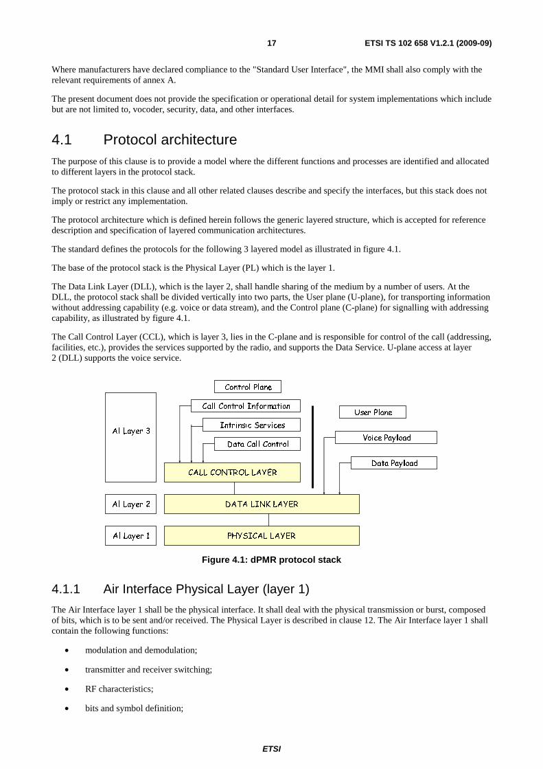
ETSI
ETSI TS 102 658 V1.2.1 (2009-09)17
Where manufacturers have declared compliance to the "Standard User Interface", the MMI shall also comply with the relevant requirements of annex A.
The present document does not provide the specification or operational detail for system implementations which include but are not limited to, vocoder, security, data, and other interfaces.
4.1 Protocol architecture The purpose of this clause is to provide a model where the different functions and processes are identified and allocated to different layers in the protocol stack.
The protocol stack in this clause and all other related clauses describe and specify the interfaces, but this stack does not imply or restrict any implementation.
The protocol architecture which is defined herein follows the generic layered structure, which is accepted for reference description and specification of layered communication architectures.
The standard defines the protocols for the following 3 layered model as illustrated in figure 4.1.
The base of the protocol stack is the Physical Layer (PL) which is the layer 1.
The Data Link Layer (DLL), which is the layer 2, shall handle sharing of the medium by a number of users. At the DLL, the protocol stack shall be divided vertically into two parts, the User plane (U-plane), for transporting information without addressing capability (e.g. voice or data stream), and the Control plane (C-plane) for signalling with addressing capability, as illustrated by figure 4.1.
The Call Control Layer (CCL), which is layer 3, lies in the C-plane and is responsible for control of the call (addressing, facilities, etc.), provides the services supported by the radio, and supports the Data Service. U-plane access at layer 2 (DLL) supports the voice service.
PHYSICAL LAYER
DATA LINK LAYER
User Plane
Voice Payload
Al Layer 1
Al Layer 2
Al Layer 3
Control Plane
CALL CONTROL LAYER
Call Control Information
Intrinsic Services
Data Payload
Data Call Control
Figure 4.1: dPMR protocol stack
4.1.1 Air Interface Physical Layer (layer 1)
The Air Interface layer 1 shall be the physical interface. It shall deal with the physical transmission or burst, composed of bits, which is to be sent and/or received. The Physical Layer is described in clause 12. The Air Interface layer 1 shall contain the following functions:
• modulation and demodulation;
• transmitter and receiver switching;
• RF characteristics;
• bits and symbol definition;

ETSI
ETSI TS 102 658 V1.2.1 (2009-09)18
• frequency and symbol synchronization;
• transmission or burst building.
4.1.2 Air Interface Data Link Layer (layer 2)
The Air Interface layer 2 shall handle logical connections and shall hide the physical medium from the upper layers. The Data Link Layer is described in clauses 11 to 14.
The main functions are as follows:
• channel coding (FEC, CRC);
• interleaving, de-interleaving and bit ordering;
• acknowledgement and retry mechanism;
• media access control and channel management;
• framing, superframe building and synchronization;
• burst and parameter definition;
• link addressing (source and/or destination);
• interfacing of voice applications (vocoder data) with the PL;
• data bearer services;
• exchanging signalling and/or user data with the CCL.
4.1.3 Air Interface Call Control Layer (layer 3)
Air Interface layer 3 (CCL) is applicable only to the C-plane, and shall be an entity for the services and facilities supported by the radio on top of the layer 2 functionality.
The CCL provides the following functions:
• establishing, maintaining and terminating of calls;
• individual or talkgroup call transmission and reception;
• destination addressing;
• support of intrinsic services (late entry, call divert, etc.);
• data call control.
4.1.4 Architectural Configurations
A network of MS and/or BS shall be configured into one of three modes, Mode 1, Mode 2 or Mode 3. Within a network all entities shall be configured with the matching mode.
4.1.4.1 Peer-to-Peer Direct Network (Mode 1)
A Peer-to-Peer Direct Network illustrated in figure 4.2 is characterized by multiple MS communicating with each other directly on a single frequency channel (i.e. MS ftx = MS frx = f1).
Peer-to-Peer operation on a given channel is governed by the MS on that channel. There is no "Master-Slave" relationship on such a channel and each MS is responsible for adhering to the channel access rules. Peer-to-Peer communication is directly between the MS.
Signalling between entities is asynchronous using a traffic channel.

ETSI
ETSI TS 102 658 V1.2.1 (2009-09)19
f1
f1
f1
f1
Figure 4.2: Peer-to-Peer Direct Network (Mode 1)
4.1.4.2 Centralized Repeater Network (Mode 2)
A Centralized BS Network illustrated in figure 4.3 is characterized by multiple MS communicating with a BS on up-link and down-link channels (i.e. MS ftx = BS frx = fuplink, MS frx = BS ftx = fdownlink). All Centralized
communication is via the BS. For polite operation, the BS is required to indicate on the down-link when the up-link is busy.
Signalling between entities is asynchronous using a traffic channel.
fdo wn
fup
fdo wn
fup
f do wn
fup
fup
fdo wn
BA SE STA TION
W IREINTERFA CE
(UNDEFINED)
FIXED
EQUIPMENT
Figure 4.3: Centralized Repeater Network (Mode 2)
4.1.4.3 Managed Centralized Repeater Network (Mode 3)
A Managed Centralized BS Network illustrated in figure 4.4 is characterized by multiple MS communicating with a BS on up-link and down-link channels (i.e. MS ftx = BS frx = fuplink, MS frx = BS ftx = fdownlink). There is a "Master-Slave"
relationship on such a channel where the BS is considered the Master and the MS are considered the Slaves. All Centralized communication is via the BS.
A Mode 3 physical channel may be operating as a beacon channel or a traffic channel.
4.1.4.3.1 Beacon Channel
Signalling between entities is synchronous. Frames are transmitted by the BS to provide MS bit and slot timing. All call set-ups use a beacon channel.
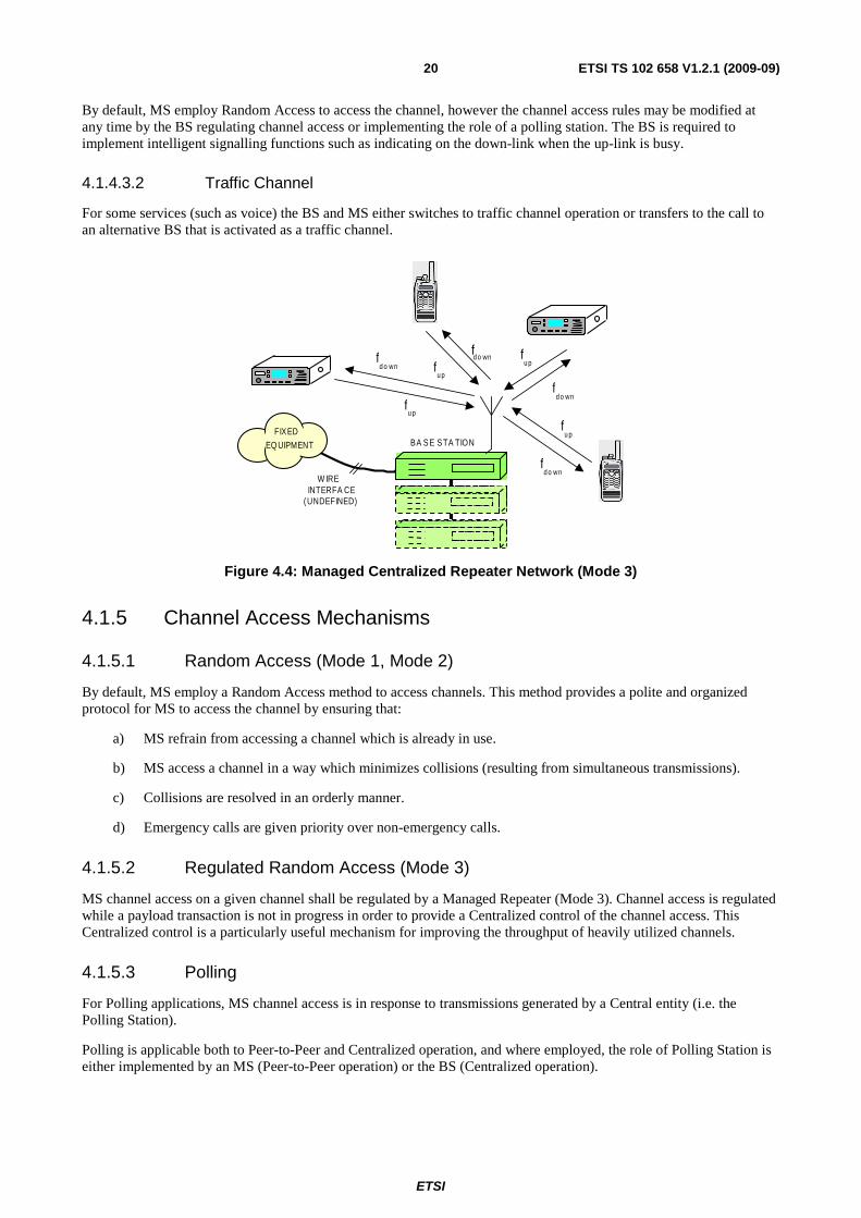
ETSI
ETSI TS 102 658 V1.2.1 (2009-09)20
By default, MS employ Random Access to access the channel, however the channel access rules may be modified at any time by the BS regulating channel access or implementing the role of a polling station. The BS is required to implement intelligent signalling functions such as indicating on the down-link when the up-link is busy.
4.1.4.3.2 Traffic Channel
For some services (such as voice) the BS and MS either switches to traffic channel operation or transfers to the call to an alternative BS that is activated as a traffic channel.
fd o wn
fu p
fd o wn
fd o wn
fu p
fu p
W IREINTERFA CE
(UNDEFINED)
FIXED
EQ UIPMENT
fu pf
d o wn
BA SE STA TION
Figure 4.4: Managed Centralized Repeater Network (Mode 3)
4.1.5 Channel Access Mechanisms
4.1.5.1 Random Access (Mode 1, Mode 2)
By default, MS employ a Random Access method to access channels. This method provides a polite and organized protocol for MS to access the channel by ensuring that:
a) MS refrain from accessing a channel which is already in use.
b) MS access a channel in a way which minimizes collisions (resulting from simultaneous transmissions).
c) Collisions are resolved in an orderly manner.
d) Emergency calls are given priority over non-emergency calls.
4.1.5.2 Regulated Random Access (Mode 3)
MS channel access on a given channel shall be regulated by a Managed Repeater (Mode 3). Channel access is regulated while a payload transaction is not in progress in order to provide a Centralized control of the channel access. This Centralized control is a particularly useful mechanism for improving the throughput of heavily utilized channels.
4.1.5.3 Polling
For Polling applications, MS channel access is in response to transmissions generated by a Central entity (i.e. the Polling Station).
Polling is applicable both to Peer-to-Peer and Centralized operation, and where employed, the role of Polling Station is either implemented by an MS (Peer-to-Peer operation) or the BS (Centralized operation).
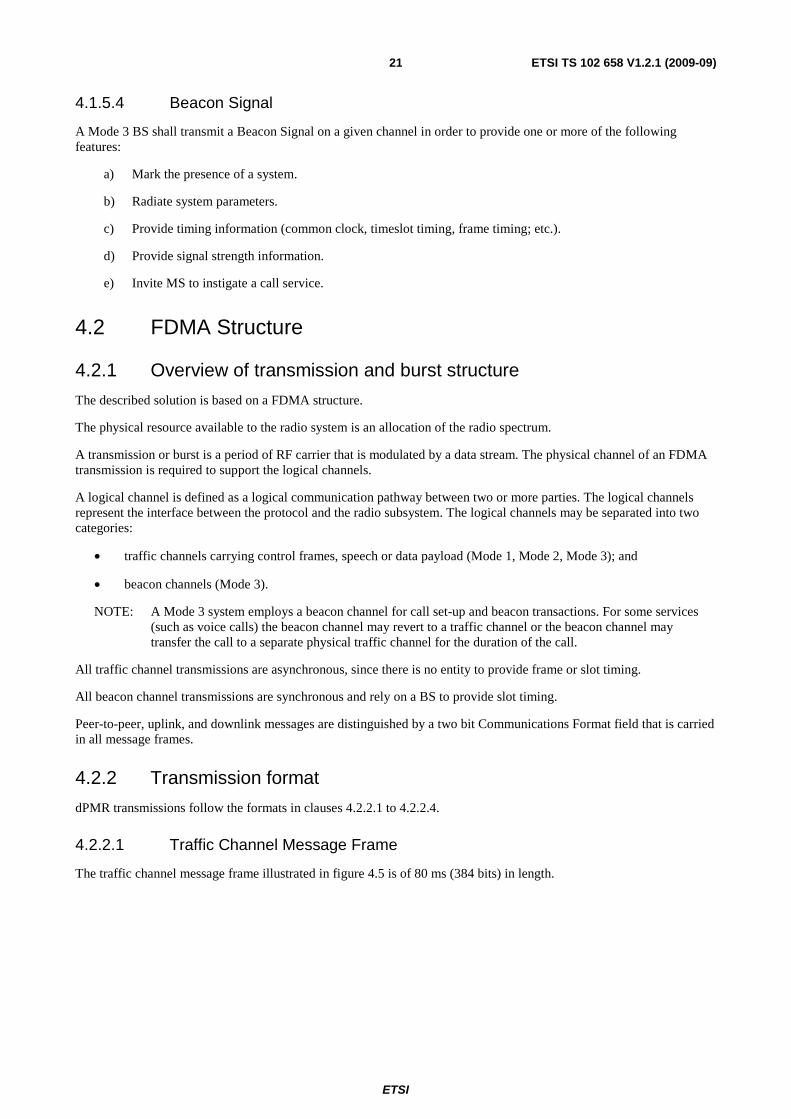
ETSI
ETSI TS 102 658 V1.2.1 (2009-09)21
4.1.5.4 Beacon Signal
A Mode 3 BS shall transmit a Beacon Signal on a given channel in order to provide one or more of the following features:
a) Mark the presence of a system.
b) Radiate system parameters.
c) Provide timing information (common clock, timeslot timing, frame timing; etc.).
d) Provide signal strength information.
e) Invite MS to instigate a call service.
4.2 FDMA Structure
4.2.1 Overview of transmission and burst structure
The described solution is based on a FDMA structure.
The physical resource available to the radio system is an allocation of the radio spectrum.
A transmission or burst is a period of RF carrier that is modulated by a data stream. The physical channel of an FDMA transmission is required to support the logical channels.
A logical channel is defined as a logical communication pathway between two or more parties. The logical channels represent the interface between the protocol and the radio subsystem. The logical channels may be separated into two categories:
• traffic channels carrying control frames, speech or data payload (Mode 1, Mode 2, Mode 3); and
• beacon channels (Mode 3).
NOTE: A Mode 3 system employs a beacon channel for call set-up and beacon transactions. For some services (such as voice calls) the beacon channel may revert to a traffic channel or the beacon channel may transfer the call to a separate physical traffic channel for the duration of the call.
All traffic channel transmissions are asynchronous, since there is no entity to provide frame or slot timing.
All beacon channel transmissions are synchronous and rely on a BS to provide slot timing.
Peer-to-peer, uplink, and downlink messages are distinguished by a two bit Communications Format field that is carried in all message frames.
4.2.2 Transmission format
dPMR transmissions follow the formats in clauses 4.2.2.1 to 4.2.2.4.
4.2.2.1 Traffic Channel Message Frame
The traffic channel message frame illustrated in figure 4.5 is of 80 ms (384 bits) in length.
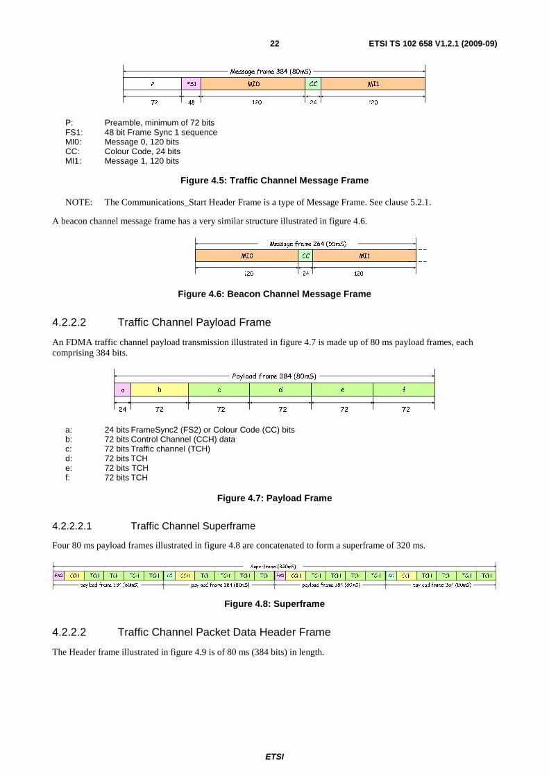
ETSI
ETSI TS 102 658 V1.2.1 (2009-09)22
Message frame 384 (80mS)
P MI0 CC MI1FS1
72 120 12048 24
P: Preamble, minimum of 72 bits FS1: 48 bit Frame Sync 1 sequence MI0: Message 0, 120 bits CC: Colour Code, 24 bits MI1: Message 1, 120 bits
Figure 4.5: Traffic Channel Message Frame
NOTE: The Communications_Start Header Frame is a type of Message Frame. See clause 5.2.1.
A beacon channel message frame has a very similar structure illustrated in figure 4.6.
Message frame 264 (55mS)
MI0 CC MI1
120 12024
Figure 4.6: Beacon Channel Message Frame
4.2.2.2 Traffic Channel Payload Frame
An FDMA traffic channel payload transmission illustrated in figure 4.7 is made up of 80 ms payload frames, each comprising 384 bits.
Payload frame 384 (80mS)
a b c d e f
7272727224 72
a: 24 bits FrameSync2 (FS2) or Colour Code (CC) bits b: 72 bits Control Channel (CCH) data c: 72 bits Traffic channel (TCH) d: 72 bits TCH e: 72 bits TCH f: 72 bits TCH
Figure 4.7: Payload Frame
4.2.2.2.1 Traffic Channel Superframe
Four 80 ms payload frames illustrated in figure 4.8 are concatenated to form a superframe of 320 ms.
payload frame 384 (80mS)payload frame 384 (80mS)payload frame 384 (80mS)payload frame 384 (80mS)
FS2 CCH TCH TCH TCH TCH
Superframe (320mS)
CC CCH TCH TCH TCH TCH FS2 CCH TCH TCH TCH TCH CC CCH TCH TCH TCH TCH
Figure 4.8: Superframe
4.2.2.2 Traffic Channel Packet Data Header Frame
The Header frame illustrated in figure 4.9 is of 80 ms (384 bits) in length.
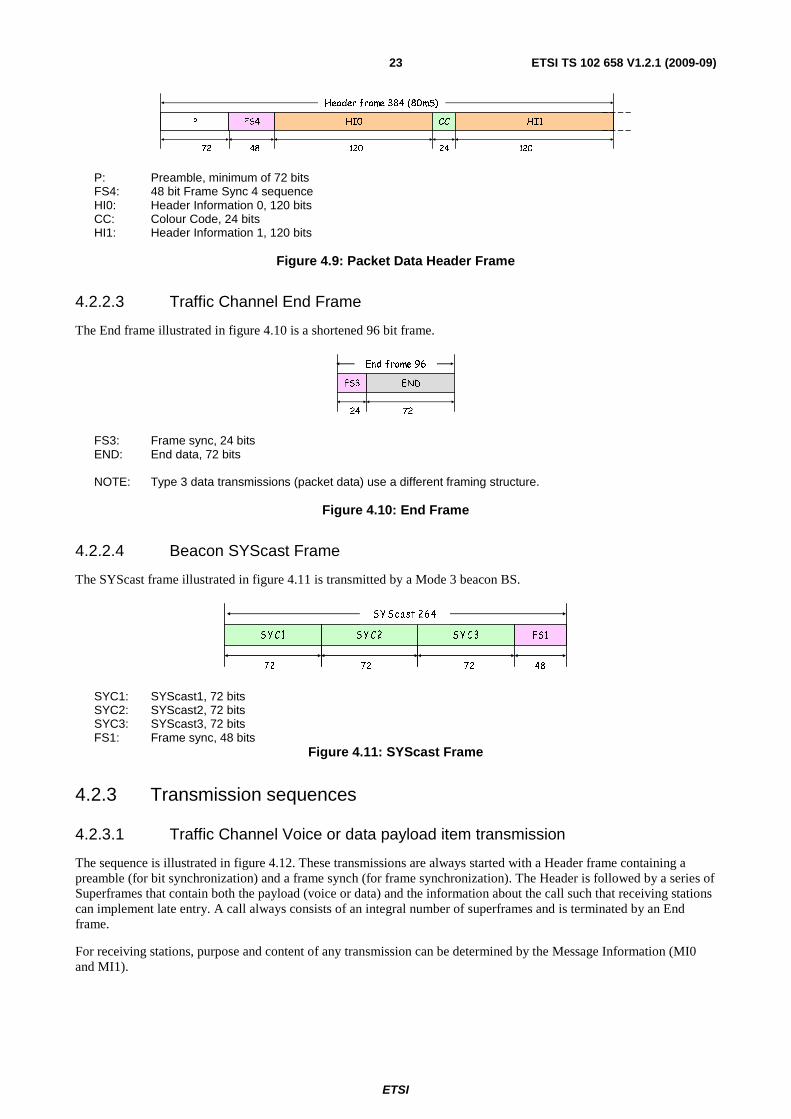
ETSI
ETSI TS 102 658 V1.2.1 (2009-09)23
Header frame 384 (80mS)
P HI0 CC HI1FS4
72 120 12048 24
P: Preamble, minimum of 72 bits FS4: 48 bit Frame Sync 4 sequence HI0: Header Information 0, 120 bits CC: Colour Code, 24 bits HI1: Header Information 1, 120 bits
Figure 4.9: Packet Data Header Frame
4.2.2.3 Traffic Channel End Frame
The End frame illustrated in figure 4.10 is a shortened 96 bit frame.
7224
End frame 96
ENDFS3
FS3: Frame sync, 24 bits END: End data, 72 bits NOTE: Type 3 data transmissions (packet data) use a different framing structure.
Figure 4.10: End Frame
4.2.2.4 Beacon SYScast Frame
The SYScast frame illustrated in figure 4.11 is transmitted by a Mode 3 beacon BS.
FS1S Y C 3SY C2S Y C1
72 72 72
SY Sca st 2 64
48
SYC1: SYScast1, 72 bits SYC2: SYScast2, 72 bits SYC3: SYScast3, 72 bits FS1: Frame sync, 48 bits
Figure 4.11: SYScast Frame
4.2.3 Transmission sequences
4.2.3.1 Traffic Channel Voice or data payload item transmission
The sequence is illustrated in figure 4.12. These transmissions are always started with a Header frame containing a preamble (for bit synchronization) and a frame synch (for frame synchronization). The Header is followed by a series of Superframes that contain both the payload (voice or data) and the information about the call such that receiving stations can implement late entry. A call always consists of an integral number of superframes and is terminated by an End frame.
For receiving stations, purpose and content of any transmission can be determined by the Message Information (MI0 and MI1).

ETSI
ETSI TS 102 658 V1.2.1 (2009-09)24
SFH SF SF ESFSF
H: Header frame SF: Superframe E: End frame
Figure 4.12: Voice or Data Payload continuous transmission
4.2.3.2 Traffic Channel Call set up, service request, etc.
The transmission illustrated in figure 4.13 may be sent by Mode 1 and Mode 2 systems on a traffic channel at the start of a call. They are a concatenation of a Header frame and an End frame. Their purpose is to inform the receiving station of the call, type of call or information required.
EH
Figure 4.13: Call Set-up
The transmission may be sent for an individual call manually as a kind of "polling call" to check if the called party is listening on the same channel.
These transmissions may be sent automatically by as the first part of an OACSU sequence or for initiating an individual data call.
4.2.3.3 Traffic Channel Acknowledgement
Traffic channel acknowledgements are sent in response to applicable messages back to the originator. Acknowledgements are a type of Header that contains information such as confirmation of received data, errors in received data, etc.
H
Figure 4.14: Acknowledgement
4.2.3.4 Traffic Channel Status request acknowledgements
Traffic channel status request acknowledgements illustrated in figure 4.15 are sent by Mode 1 and Mode 2 systems. As the status information is contained within the End frame then the response of a receiving station to a status request call shall be a Header + End frame pair.
EH
Figure 4.15: Status Request Acknowledgement
4.2.3.5 Traffic Channel Disconnection
Sending stations can signal that all exchanges of a call have been completed by transmitting a disconnection request. This is a Header + End frame pair that is repeated illustrated in figure 4.16.
EH EH
Figure 4.16: Disconnection
These transmissions may be sent manually as confirmation to the called party that the communication is complete.
These transmissions may also be sent automatically to the called party to indicate that an individual data call is completed.
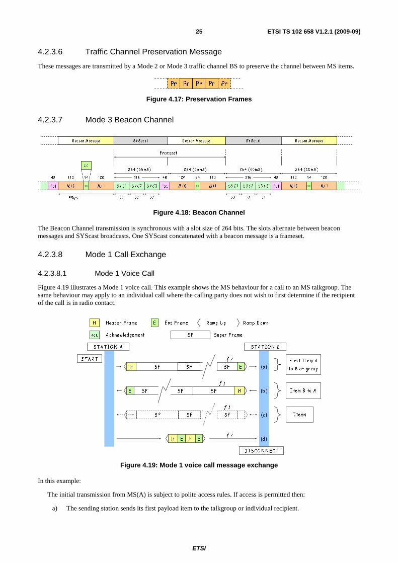
ETSI
ETSI TS 102 658 V1.2.1 (2009-09)25
4.2.3.6 Traffic Channel Preservation Message
These messages are transmitted by a Mode 2 or Mode 3 traffic channel BS to preserve the channel between MS items.
Pr Pr Pr PrPr
Figure 4.17: Preservation Frames
4.2.3.7 Mode 3 Beacon Channel
55mS
120 24 120
CC
26 4 (55 mS )
S Y C1
26 4 (55 mS )
48
FS 1
216
72 72 72
S Y C 2 S Y C 3
F ra meset
M I1M I0 c c
120 24 120
26 4 (55 mS )
S Y C1
26 4 (55 mS )
48
FS 1
216
72 72 72
S Y C 2 S Y C 3 M I1M I0 c c
SY Scast SY Scas tB eacon M ess age B eacon M es s ageB eacon M ess age
120 24 12048
FS 1 M I1M I0 c c
Figure 4.18: Beacon Channel
The Beacon Channel transmission is synchronous with a slot size of 264 bits. The slots alternate between beacon messages and SYScast broadcasts. One SYScast concatenated with a beacon message is a frameset.
4.2.3.8 Mode 1 Call Exchange
4.2.3.8.1 Mode 1 Voice Call
Figure 4.19 illustrates a Mode 1 voice call. This example shows the MS behaviour for a call to an MS talkgroup. The same behaviour may apply to an individual call where the calling party does not wish to first determine if the recipient of the call is in radio contact.
S T A R T
H E H E
S T A T IO N A S T A T I O N B
D IS C O N N E C T
S F S F S F
S F HE S F S F
f 1
f 1
F irst Item A
to B or gr oup
Item B to A
Items
f 1
S FH S F S F E
(c)
(a)
(b )
(d)
f 1
H
AC K
H eader F rame
A ck now ledgement S up er F r ameS F
E E nd F r ame R amp U p R amp D ow n
Figure 4.19: Mode 1 voice call message exchange
In this example:
The initial transmission from MS(A) is subject to polite access rules. If access is permitted then:
a) The sending station sends its first payload item to the talkgroup or individual recipient.
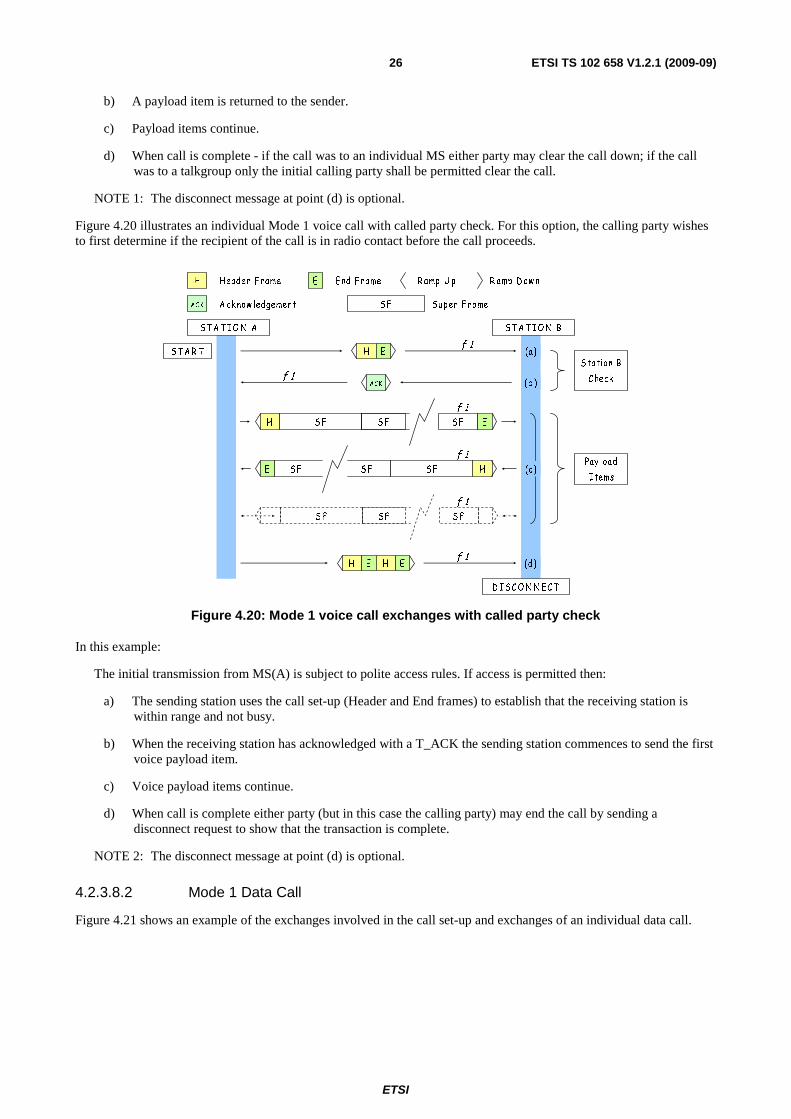
ETSI
ETSI TS 102 658 V1.2.1 (2009-09)26
b) A payload item is returned to the sender.
c) Payload items continue.
d) When call is complete - if the call was to an individual MS either party may clear the call down; if the call was to a talkgroup only the initial calling party shall be permitted clear the call.
NOTE 1: The disconnect message at point (d) is optional.
Figure 4.20 illustrates an individual Mode 1 voice call with called party check. For this option, the calling party wishes to first determine if the recipient of the call is in radio contact before the call proceeds.
H
AC K
H eader F rame
A ck now ledgement Sup er F rameS F
E E nd F rame R amp U p R amp D ow n
S T A R T H E
AC K
H E H E
S T A T IO N A ST A T IO N B
D ISC O N N E C T
S F SF S F
f 1
f 1
S F S F SF HE
f 1
f 1
S tation B
C heck
Pay load
Items
f 1
S FH S F SF E
(c)
(a)
(b )
(d)
f 1
Figure 4.20: Mode 1 voice call exchanges with called party check
In this example:
The initial transmission from MS(A) is subject to polite access rules. If access is permitted then:
a) The sending station uses the call set-up (Header and End frames) to establish that the receiving station is within range and not busy.
b) When the receiving station has acknowledged with a T_ACK the sending station commences to send the first voice payload item.
c) Voice payload items continue.
d) When call is complete either party (but in this case the calling party) may end the call by sending a disconnect request to show that the transaction is complete.
NOTE 2: The disconnect message at point (d) is optional.
4.2.3.8.2 Mode 1 Data Call
Figure 4.21 shows an example of the exchanges involved in the call set-up and exchanges of an individual data call.
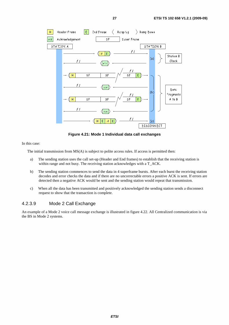
ETSI
ETSI TS 102 658 V1.2.1 (2009-09)27
H E
ACK
ACK
AC K
H E H E
S T A TIO N A S TA T IO N B
D IS CO N N EC T
S FH S F S F E
S FH S F S F E
f 1
f 1
f 1
f 1
f 1
f 1
f 1
S tation B
Check
D ata
F ragments
A to B
(c)
(a)
(b )
H
ACK
Header F rame
A cknow ledgement S up er F rameS F
E End F rame R amp U p R amp D ow n
Figure 4.21: Mode 1 Individual data call exchanges
In this case:
The initial transmission from MS(A) is subject to polite access rules. If access is permitted then:
a) The sending station uses the call set-up (Header and End frames) to establish that the receiving station is within range and not busy. The receiving station acknowledges with a T_ACK.
b) The sending station commences to send the data in 4 superframe bursts. After each burst the receiving station decodes and error checks the data and if there are no uncorrectable errors a positive ACK is sent. If errors are detected then a negative ACK would be sent and the sending station would repeat that transmission.
c) When all the data has been transmitted and positively acknowledged the sending station sends a disconnect request to show that the transaction is complete.
4.2.3.9 Mode 2 Call Exchange
An example of a Mode 2 voice call message exchange is illustrated in figure 4.22. All Centralized communication is via the BS in Mode 2 systems.
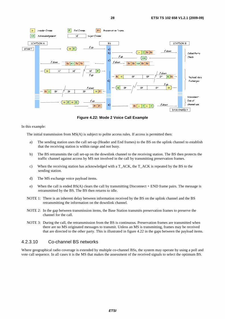
ETSI
ETSI TS 102 658 V1.2.1 (2009-09)28
H Header Frame
ACK Acknowledgement Super FrameSF
End FrameE Pr Preservation Frame
START H E
SFH SF SF E
H E H E
STATION A BS
DISCONNECT
STATION B
ACK
f up
f up
f up
f up
f downPrH E Pr
PrSFH SF SF E
f down
Pr
f downPr H E H E
a)
b)
c)f down
Pr Pr PrPr ACKf down
Pr PrACK Pr
PrPr
f up
SF SF SF HE
PrSF HSF SFE
f down
Pr
Payload item
Exchanges
Called Party
Check
Disconnect -
End of
channel usee)
d)
Figure 4.22: Mode 2 Voice Call Example
In this example:
The initial transmission from MS(A) is subject to polite access rules. If access is permitted then:
a) The sending station uses the call set-up (Header and End frames) to the BS on the uplink channel to establish that the receiving station is within range and not busy.
b) The BS retransmits the call set-up on the downlink channel to the receiving station. The BS then protects the traffic channel against access by MS not involved in the call by transmitting preservation frames.
c) When the receiving station has acknowledged with a T_ACK, the T_ACK is repeated by the BS to the sending station.
d) The MS exchange voice payload items.
e) When the call is ended BS(A) clears the call by transmitting Disconnect + END frame pairs. The message is retransmitted by the BS. The BS then returns to idle.
NOTE 1: There is an inherent delay between information received by the BS on the uplink channel and the BS retransmitting the information on the downlink channel.
NOTE 2: In the gap between transmission items, the Base Station transmits preservation frames to preserve the channel for the call.
NOTE 3: During the call, the retransmission from the BS is continuous. Preservation frames are transmitted when there are no MS originated messages to transmit. Unless an MS is transmitting, frames may be received that are directed to the other party. This is illustrated in figure 4.22 in the gaps between the payload items.
4.2.3.10 Co-channel BS networks
Where geographical radio coverage is extended by multiple co-channel BSs, the system may operate by using a poll and vote call sequence. In all cases it is the MS that makes the assessment of the received signals to select the optimum BS.

ETSI
ETSI TS 102 658 V1.2.1 (2009-09)29
BASE STATIONBASE STATION
BASE STATION
A
B
C
D
FMS Poll
MS Rx Signal
COCHI3
A
A
C D
B
A E
BS1
BS2BS3COCHI2
COCHI1
BS3Tx Burst
BS1Tx Burst
BS2Tx Burst
Figure 4.23: Co-channel Base Station networks
A network employing three co-channel BSs is illustrated in figure 4.23. An MS wishes to select the BS that will provide the best signal quality for the call.
Referring to the illustration in figure 4.23:
a) The MS makes an initial polling call to all BSs within range.
b) The BS with the highest assigned co-channel address (COCHI3 in this example) send s a response to the poll message. The timing of the poll message is determined by the particular COCHI index number.
c) The BS assigned as COCHI2 sends a response to the poll message.
d) The BS assigned as COCHI1 sends a response to the poll message.
e) The MS assess the signal quality of each of the poll responses. In this example, BS2 has the best signal quality. The MS then sends an acknowledgement to the gateway address COCHI2.
f) BS2 then asserts its carrier transmitting protection frames until the MS transmits its first call set-up or payload burst.
4.2.3.11 Mode 3 Operation
When idle, MSs listen to a beacon channel. All call services originate on this beacon with an exchange of call set-up messages. For some services such as voice, the MS participants in the call are transferred to a traffic channel for the transaction. When the call is complete the MSs return to the beacon channel.
An example of a Mode 3 call set-up is illustrated in figure 4.24. MS(A) and MS(B) is initially tuned to the Beacon Channel. This example illustrates a voice call set-up where the call is transferred to a traffic channel for the transaction.

ETSI
ETSI TS 102 658 V1.2.1 (2009-09)30
- B eacon M essages- S YS cast - R ecip ient of a m essage
A D G O TO
C H A N N E L
- Appended D ata
F ram e
- Preservation
F ram ePR ES
ALO HA
M S (A)
U plink
M S (B )
U p link
ALO HA A LO HAA HO Y
(B)A LO HA
G O T O
CH ANNEL
A B
C
D
Beacon
D ow nlink
110 +110 +110 +110+110 +110 =66 0 m S
A D G O TO
C H A N N E L
E
ALOH AGO T O
CHANNEL
A D G O TO
C H A N NE LALOH AALO HA
R EQ
SER V
ACK
P R E SPR ES PR ES PR ES PR ES PR ES PR ES Traf f ic Channel
D ow nlink
Figure 4.24: Mode 3 Beacon Channel Individual Voice Call Set-up
In this example:
The initial request for a transmission from MS(A) is permission subject to fully managed access rules. If access is permitted then:
a) The calling MS sends a service request to the beacon.
b) The beacon sends an AHOY message to MS(B) to determine if MS(B) is in radio contact.
c) MS(B) sends an acknowledgement to the beacon.
d) The beacon sends a Goto Channel message to MS(A) and MS(B) to direct the MSs to a traffic channel for the transaction. The system activates the traffic channel. The Goto Channel message contains the address of the called MS and the uplink and downlink frequencies of the traffic channel. The beacon may also concatenate an Appended Data message to the Goto Channel that contains the address of the calling MS.
e) Since the Goto Channel message is not acknowledged, the BS may repeat this message to the MSs.
If unacknowledged messages containing appended data are repeated there shall be at least one SYScast frame inserted between the two messages.
An example of a group call set-up is illustrated in figure 4.25.
1 10 +1 10 +11 0 +11 0 = 4 4 0 m S
11 0 +1 10 =2 2 0 m S
C
A LO H A
M S (A)
U plin k
M S (B )
U p lin k
A LO H A A LO H AG O TO
CH AN N EL
G O TO
CH AN N EL
A B
B ea c on
D ow n lin k
T raf f ic Chan ne l D o w n link
A D G O TO
CH A N NE LA LO H A
A D G O TO
CH A N NE LA LO H A
R E Q
S E R V
P RE SPR E S PR ES PR ES PR E S PR E S PR ES
- B ea c on M essages- S YS c ast - Rec ipien t o f a m essa ge
A D G O TO
C HA NN E L
- Appen d ed D ata
Cod ew o rd s
- Reservatio n
F ram ePR E S
Figure 4.25: Talkgroup Voice Call-Setup

ETSI
ETSI TS 102 658 V1.2.1 (2009-09)31
In this example:
The initial request for a transmission from MS(A) is permission subject to fully managed access rules. If access is permitted then:
a) The calling MS sends a service request to the beacon.
b) The beacon sends a Goto Channel message to MS(A) and MS(B) to direct the MSs to a traffic channel for the transaction. The system activates the traffic channel. The Goto Channel message contains the address of the called MS and the uplink and downlink frequencies of the traffic channel. The beacon may also concatenate an Appended Data message to the Goto Channel that contains the address of the calling MS.
c) Since the Goto Channel message is not acknowledged, the BS may repeat the message to the MSs.
If unacknowledged messages containing appended data are repeated there shall be at least one SYScast frame inserted between the two messages.
4.3 Addressing All entities defined in the present document shall be assigned a unique individual IDentity. MSs may also be assigned one or more group identities to form a talkgroup. MSs and talkgroups use a 24 bit Identity.
Other entities connecting to MS and BS conforming to the present document may employ different addressing formats. As an example, PSTN destinations may be described by a string of numeric digits. An IP address may be defined by a 32 bit (IPV4) or a 128 bit address (IPV6). In the present document, these destinations are defined as extended addresses.
When many different types of entity are linked in a system conforming to the present document, a way of identifying these entities is essential The present document uses Gateway Addresses that identity both destinations and certain intrinsic call services. A table listing these addresses is illustrated in clause 13.4.
4.4 Unified Data Transport Mechanism A dPMR network supports a wide range of facilities. To support these facilities, the transporting of data is a very common necessity. For example, although Short Data is a primary Mode 2 and Mode 3 data service, there are many instances where data needs to be transported to support other facilities. (For example when an MS dials a PABX or PSTN destination, the dialled digits are uploaded to the BS. This extended addressing is transported between MS and BS using the UDT. In addition, as part of the call set-up the MS may exchange complementary information. Complementary information is user data that may be passed between MS and other entities as part of another call service. To reduce the dPMR complexity, all short data, extended addressing and complementary data transport between MS and BS share this common method - the Unified Data Transport mechanism.
The UDT defines Appended_Data messages that contain principally data that may be concatenated to other message frames.
In Mode 1 and Mode 2 systems Appended_Data Messages may be concatenated to Connection_Request messages. Mode 3 systems concatenate Appended_Data carrying short data, extended addresses and complementary data to a UDT Header message.
The data in these Appended_Data messages are coded in a uniform way and support dPMR addresses, binary, BCD, 7 bit text, 8 bit octets, EN 61162-1 [1] and IP addressing. The format of Appended_Data messages is described in clause 5.6.
4.5 Complementary Data In Mode 3 systems, a feature of the Unified Data Transport mechanism is complementary data. In Mode 3 systems, complementary data may be passed from MS to BS or from BS to MS. The data sent by the UDT mechanism and the recipient is able to determine the format of the received data (binary, BCD, text, etc.).

ETSI
ETSI TS 102 658 V1.2.1 (2009-09)32
4.5.1 Support for Voice and Data call services
Complementary data may be invoked by an MS to send this data as part of another user call service. However it shall be noted that the motive for the MS to send the data and the use that the BS puts to this data is outside the scope of the present document.
EXAMPLE: A system is designed such that An MS uses the complementary data feature to send its GPS location as part of all voice call set-ups.
4.5.2 Transport of complementary data for MS control
The present document prescribes a number of facilities that use complementary data. These include:
a) MS stun/unstun.
b) MS Electronic serial number check.
The use of complementary data to provide these facilities simplifies the protocol. MS stun and ESN check is described in clause 12.
5 Frame coding The following clauses contain descriptions of the Frames and fields contained within them. The structure of the frame definition represented by the tables is as follows:
• the FIELD column gives the name or description of the field;
• the LENGTH and TRANSFER column defines the length of the field in bits;
• the MEANING contains further description of the field;
• the FEC field provides the pointer to the clauses that describe the FEC;
• the ALIAS contains a shorthand for the field;
• MNEMONIC is a description of the particular value of a field or alias.
If a field is marked RSVD, all bits of the reserved field shall be set to 02.
If a field is marked SPARE, the bits are not used by this protocol and may be set to any value.
If a field is marked N/A that means the field is not applicable for that particular message. The field shall be set to all zeros.
The differing frame structures are identified by one of four synchronization fields FS1, FS2, FS3 and FS4.
The organization of the frames is illustrated in figures 5.1 and 5.2.
The four structures that are defined for a dPMR traffic channel illustrated in figure 5.1. Traffic channels are exclusively used in Mode 1 and Mode 2 systems. Mode 3 systems use a beacon channel for call set-up. Traffic channels carry voice and data payload in a Mode 3 system.
The Packet_Data header shares the same CRC and FEC as a Message_Frame but is separately identified by a different synchronization sequence.

ETSI
ETSI TS 102 658 V1.2.1 (2009-09)33
7224
End frame
ENDFS3
Message Frame 384 (80mS)
P MI0 CC MI1FS1
72 120 12048 24
Packet Header 384 (80mS)
P HI0 CC HI1FS4
72 120 12048 24
Payload Frame 384 (80mS)
CCH TCH TCH TCH TCH
7272727224 72FS2
CC or
End Frame
Packet Data
Header
dPMR
Traffic
Channel
Message Frame
Payload Frame
Figure 5.1: dPMR Traffic Channel Frame Structures
Four structures make up a dPMR beacon frame used for Mode 3 systems illustrated in figure 5.2.
dPMR
Beacon
Channel
Beacon Channel
Downlink Frame
Downlink
Syscast Frame
Appended Data
Frame
Beacon Channel
Uplink Frame
Beacon Message frame 264
MI0 CC MI1FS1
120 12048 24
Appended Data frame 264
DI0 CC DI1
120 12024
Header frame 384 (80mS)
P MI0 CC MI1FS1
72 120 12048 24
SYScast 264
FS1
72
SYC3SYC1
487272
216
SYC2
Figure 5.2: Beacon Message Frames
A Mode 3 Beacon Channel downlink is a continuous transmission therefore the preamble field is not needed. Hence a message frame is constructed as illustrated in the Beacon Message Downlink Frame in figure 5.2. Figure 5.3 illustrates how a SYScast frame is concatenated with a beacon message to position the FS1 field in the correct position for the receiving MSs.
CC
48 120 24 120
MI1MI0FS1
120 24 120
MI1MI0
48 120 24 120
MI1MI0
264( 55mS)
216
264 (55mS)264 (55mS)
FS1SYC1
264 (55mS)
48
FS1
216
72 72 72
SYC2 SYC3 SYC1 SYC2 SYC3
Beacon Message SYScast SYScastBeacon Message Beacon Message
Beacon Frameset Beacon Frameset
Figure 5.3: Beacon Frameset Example

ETSI
ETSI TS 102 658 V1.2.1 (2009-09)34
In clauses 5.1 to 5.6, the headings prefixed by a [T] and/or a [B] to indicate if that particular message is valid for a [T]raffic channel and/or a [B]eacon channel.
5.1 Payload Frame [T] The content of a payload frame is illustrated in table 5.1.
Table 5.1: Payload frame
Alias Length Meaning FS2 or CC 24 Frame sync 2 or Colour Code
TCH 72 Payload TCH 72 Payload TCH 72 Payload TCH 72 Payload
5.2 Message_Frame [BT] The content for the Message_Frame is illustrated in table 5.2.
Table 5.2: Message_Frame content
Alias Field Length CRC + FEC Transfer P Preamble ≥ 72 none 72
FS1 Frame Sync 48 none 48
MI0 MT Message_Type 4
clause 7.6 120 PARMS Parameters for this Message Type 68 CRC+FEC CRC (8 bits) and FEC(40 bits) 8 + 40
CC Colour Code 24 clause 6.1.5 24
MI1 MT Message_Type 4
clause 7.6 120 PARMS Parameters for this Message Type 68 CRC+FEC CRC (8 bits) and FEC(40 bits) 8 + 40
The MI0 and MI1 fields are transmitted as duplicates. Where Message_Frames are illustrated by the tables in the following clauses, it is therefore only necessary to show one of the MI fields.
The purpose of the messages is defined by the Message_Type (MT). For each Message_Type (MT) defined in the present document, the parameters (PARMS) are specified in clauses 5.2.1 to 5.2.15.

ETSI
ETSI TS 102 658 V1.2.1 (2009-09)35
Table 5.3: Message_Type
Alias Length Value Uplink/ Downlink
Traffic/ Beacon
Meaning
MT 4
00002 U/D T Communications_Start header (a superframe follows)
00012 U/D T Connection_Request header (an END frame follows)
00102 U/D T Disconnect_Request header (an END frame follows)
00112 U/D BT T_ACK B_ACK (this a single frame, ACK or NACK is differentiated by the MI bits setting)
01002 D T
Traffic Channel Maintenance U System_Request header (an END frame follows)
01012 U T ACK header reply to a system request(a superframe follows)
01102 D T System Delivery Header(a superframe follows)
01112 U/D T Status Polling Response header (an END frame follows)
10002 U/D T Status Polling Request header
10012 U/D T BS_Command header(U) and response(D)
10102 U/D T BS_Access header(U) and response(D)
10112 D BT Broadcast
11002 D B
Beacon Ahoy (B_AHOY) U Beacon Random Access Request (B_RAND)
11012 - - Reserved
11102 U/D B UDT_Header
11112 U/D B UDT_Appended Data
NOTE: BS_Command header and response, and BS_Access header and response are used for transactions directly between MS and BS.
5.2.1 Communications_Start Header [T]
This is a Message_Frame identified by MT=00002.The header is transmitted at the start of a traffic channel transmission
item. A payload superframe is concatenated to this header.
Table 5.4: Communications_Start Header
Alias Alias Alias Length Value Meaning MT 4 00002 Message type = Communications Start Header
PARMS
ID0 + 1 24 Called Station ID or gateway ID2 + 3 24 Calling Station ID or gateway
M 3 Communications Mode V 2 Version F 2 Comms Format
EP 1 Emergency Priority PM 1 N/A Not Applicable for this particular message
MI MI_TYPE 3 Message_Information_Type MI_DET 8 Message Detail
5.2.1.1 Concatenated Superframe to a Communications_Start Header [T]
The structure of a superframe is illustrated in figure 5.4.
payload frame 384 (80mS)payload frame 384 (80mS)payload frame 384 (80mS)payload frame 384 (80mS)
FS2 CCH TCH TCH TCH TCH
Superframe (320mS)
CC CCH TCH TCH TCH TCH FS2 CCH TCH TCH TCH TCH CC CCH TCH TCH TCH TCH
Figure 5.4: Superframe Structure

ETSI
ETSI TS 102 658 V1.2.1 (2009-09)36
The content for the four frames that make up a superframe are illustrated in tables 5.5 to 5.8.
Table 5.5: Superframe content, payload frame 1
FRAME 1 Alias Meaning Length FEC Transfer Rate FS2 Frame Sync 24 None 24
CCH
FN Frame Number 2
See clause 7.5 72
25 bps ID0 Called ID (most sig' 12 bits) 12 38 bps M Communications Mode 3 38 bps V Version 2 25 bps F Comms format 2 25 bps
EP Emergency Priority 1 12 bps RSVD Reserved 1 SLD Slow Data 18 225 bps
CRC 7 FEC 24
TCH Payload 72 × 4 288
Table 5.6: Superframe content, payload frame 2
FRAME 2 Alias Meaning Length FEC Transfer Rate CC Colour Code 24 Clause 6.1.5 24
CCH
FN Frame Number 2
See clause 7.5 72
25 bps ID1 Called ID (least sig' 12 bits) 12 38 bps M Communications Mode 3 38 bps V Version 2 25 bps F Comms_Format 2 25 bps
EP Emergency Priority 1 12 bps RSVD Reserved 1 SLD Slow_Data 18 225 bps
CRC 7 FEC 24
TCH Payload 72 × 4 288
Table 5.7: Superframe content, payload frame 3
FRAME 3 Alias Meaning Length FEC Transfer Rate FS2 Frame Sync 24 None 24
CCH
FN Frame Number 2
See clause 7.5 72
25 bps ID2 Calling ID (most sig' 12 bits) 12 38 bps M Communications Mode 3 38 bps V Version 2 25 bps F Comms_Format 2 25 bps
EP Emergency Priority 1 12 bps RSVD Reserved 1 SLD Slow_Data 18 225 bps
CRC 7 FEC 24
TCH Payload 72 × 4 288

ETSI
ETSI TS 102 658 V1.2.1 (2009-09)37
Table 5.8: Superframe content, payload frame 4
FRAME 4 Alias Meaning Length FEC Transfer Rate CC Colour Code 24 Clause 6.1.5 24
CCH
FN Frame Number 2
See clause 7.5 72
25 bps ID3 Calling ID (least sig 12 bits) 12 38 bps M Communications Mode 3 38 bps V Version 2 25 bps F Comms_Format 2 25 bps
EP Emergency Priority 1 12 bps RSVD Reserved 1 SLD Slow_Data 18 225 bps
CRC 7 FEC 24
TCH Payload 72 × 4 288
5.2.2 Connection_Request Header [T]
This is a Message_Frame identified by MT=00012.
Table 5.8a: Connection_Request Header Message
Alias Alias Alias Length Value Meaning MT 4 00012 Message Type = Connection_Request Header
PARMS
ID0 + 1 24 Called Station ID or gateway ID2 + 3 24 Calling Station ID or gateway
M 3 Communications Mode V 2 Version F 2 Comms Format
EP 1 Emergency Priority PM 1 N/A Not Applicable for this particular message
MI MI_TYPE 3 MI_DET 8
5.2.2.1 Called Party Check [T]
A Called_Party Check Header message is used in Mode 1 and Mode 2 systems and is identified as a Connection_Request message with M in the range 0002 to 1012.
Table 5.9: Called Party Check
Alias Alias Alias Length Value Meaning MT 4 00012 Message Type = Connection_Request
Header
PARMS
ID0 + 1 24 Called Station ID or gateway ID2 + 3 24 Calling Station ID or gateway
M 3 0002 to 1012 Communications Mode V 2 Version F 2 Comms Format
EP 1 Emergency Priority PM 1 N/A Not Applicable for this particular message
MI MI_TYPE 3 MI_DET 8
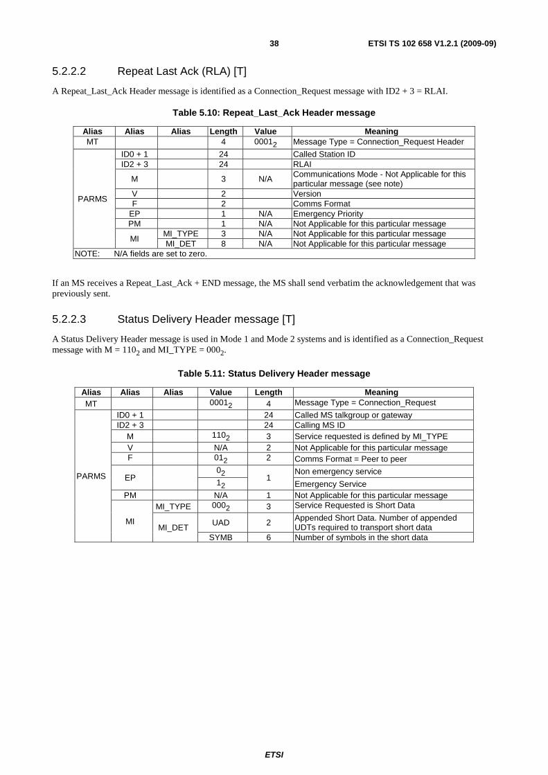
ETSI
ETSI TS 102 658 V1.2.1 (2009-09)38
5.2.2.2 Repeat Last Ack (RLA) [T]
A Repeat_Last_Ack Header message is identified as a Connection_Request message with ID2 + 3 = RLAI.
Table 5.10: Repeat_Last_Ack Header message
Alias Alias Alias Length Value Meaning MT 4 00012 Message Type = Connection_Request Header
PARMS
ID0 + 1 24 Called Station ID ID2 + 3 24 RLAI
M 3 N/A Communications Mode - Not Applicable for this particular message (see note)
V 2 Version F 2 Comms Format
EP 1 N/A Emergency Priority PM 1 N/A Not Applicable for this particular message
MI MI_TYPE 3 N/A Not Applicable for this particular message MI_DET 8 N/A Not Applicable for this particular message
NOTE: N/A fields are set to zero.
If an MS receives a Repeat_Last_Ack + END message, the MS shall send verbatim the acknowledgement that was previously sent.
5.2.2.3 Status Delivery Header message [T]
A Status Delivery Header message is used in Mode 1 and Mode 2 systems and is identified as a Connection_Request message with M = 1102 and MI_TYPE = 0002.
Table 5.11: Status Delivery Header message
Alias Alias Alias Value Length Meaning MT 00012 4 Message Type = Connection_Request
PARMS
ID0 + 1 24 Called MS talkgroup or gateway ID2 + 3 24 Calling MS ID
M 1102 3 Service requested is defined by MI_TYPE V N/A 2 Not Applicable for this particular message F 012 2 Comms Format = Peer to peer
EP 02
1 Non emergency service
12 Emergency Service PM N/A 1 Not Applicable for this particular message
MI
MI_TYPE 0002 3 Service Requested is Short Data
MI_DET UAD 2 Appended Short Data. Number of appended
UDTs required to transport short data SYMB 6 Number of symbols in the short data
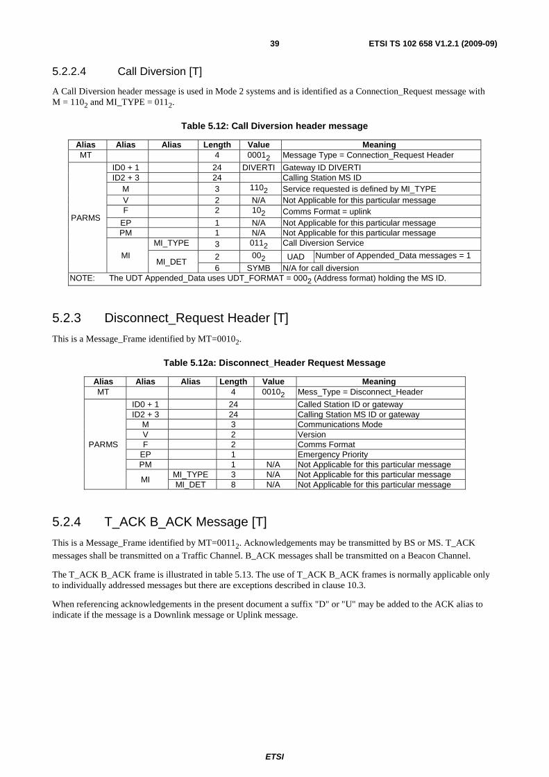
ETSI
ETSI TS 102 658 V1.2.1 (2009-09)39
5.2.2.4 Call Diversion [T]
A Call Diversion header message is used in Mode 2 systems and is identified as a Connection_Request message with M = 1102 and MI_TYPE = 0112.
Table 5.12: Call Diversion header message
Alias Alias Alias Length Value Meaning MT 4 00012 Message Type = Connection_Request Header
PARMS
ID0 + 1 24 DIVERTI Gateway ID DIVERTI ID2 + 3 24 Calling Station MS ID
M 3 1102 Service requested is defined by MI_TYPE V 2 N/A Not Applicable for this particular message F 2 102 Comms Format = uplink
EP 1 N/A Not Applicable for this particular message PM 1 N/A Not Applicable for this particular message
MI
MI_TYPE 3 0112 Call Diversion Service
MI_DET 2 002 UAD Number of Appended_Data messages = 1
6 SYMB N/A for call diversion NOTE: The UDT Appended_Data uses UDT_FORMAT = 0002 (Address format) holding the MS ID.
5.2.3 Disconnect_Request Header [T]
This is a Message_Frame identified by MT=00102.
Table 5.12a: Disconnect_Header Request Message
Alias Alias Alias Length Value Meaning MT 4 00102 Mess_Type = Disconnect_Header
PARMS
ID0 + 1 24 Called Station ID or gateway ID2 + 3 24 Calling Station MS ID or gateway
M 3 Communications Mode V 2 Version F 2 Comms Format
EP 1 Emergency Priority PM 1 N/A Not Applicable for this particular message
MI MI_TYPE 3 N/A Not Applicable for this particular message MI_DET 8 N/A Not Applicable for this particular message
5.2.4 T_ACK B_ACK Message [T]
This is a Message_Frame identified by MT=00112. Acknowledgements may be transmitted by BS or MS. T_ACK
messages shall be transmitted on a Traffic Channel. B_ACK messages shall be transmitted on a Beacon Channel.
The T_ACK B_ACK frame is illustrated in table 5.13. The use of T_ACK B_ACK frames is normally applicable only to individually addressed messages but there are exceptions described in clause 10.3.
When referencing acknowledgements in the present document a suffix "D" or "U" may be added to the ACK alias to indicate if the message is a Downlink message or Uplink message.

ETSI
ETSI TS 102 658 V1.2.1 (2009-09)40
Table 5.13: T_ACK B_ACK frame content
Alias Alias Alias Length Value Meaning MT 4 00112 Mess_Type = T_ACK B_ACK
PARMS
ID0 + 1 24 Station ID or gateway address that
originated the message for which this acknowledgement is being sent
ID2 + 3 24 Station ID or gateway that is sending this Acknowledgement
M 3 Communications Mode V 2 Version F 2 Comms Format
EP 1 Emergency Priority PM 1 N/A Not Applicable for this particular message
MI MI_TYPE 3 Message information Type MI_DET 8 Reason
5.2.4.1 Message Information for acknowledgements
Table 5.14: Acknowledgement types
Alias MI_TYPE Definition B_ACK
B_NACK B_WACK B_QACK
0002 Acknowledgement - Acknowledgement type defined by REASON
Acknowledgements transmitted on a Beacon Channel
T_ACK
0012 ACK (Rx OK) Acknowledgements transmitted on a Traffic Channel
0102 NACK (data error, resend request)
0112 NACK (request denied)
Other Reserved
Table 5.15: Acknowledgement Information
MI_DET Definition 0 Reserved
1 to 255 ACK / NACK status (reason see clause 5.5.25)
5.2.5 Maintenance_Message [T]
This is a Message_Frame identified by MT=01002.
The message is transmitted by a BS to provide traffic channel call maintenance. Maintenance messages are not acknowledged. The functions that maintenance messages provide are:
a) An Idle Message.
b) A Preservation Message.
c) A protection message.
d) Guard Message.
For this class of message MI_TYPE = 0102 to 1112 is reserved.
This message shall not be transmitted by an MS.
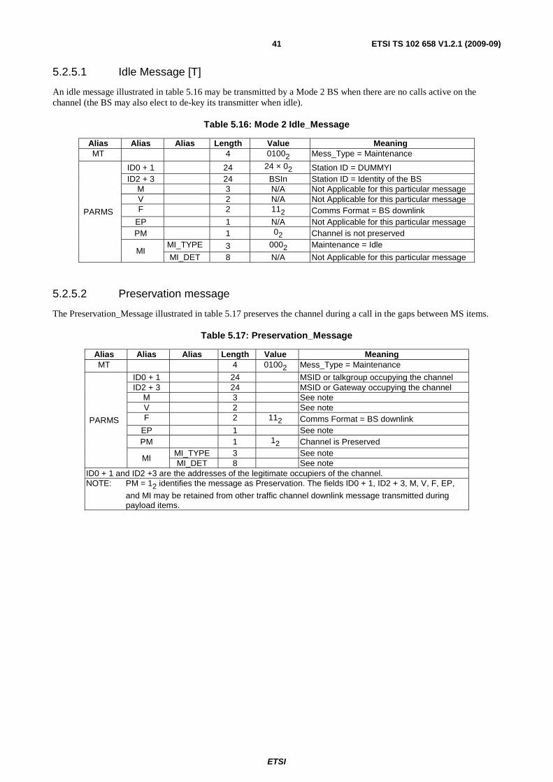
ETSI
ETSI TS 102 658 V1.2.1 (2009-09)41
5.2.5.1 Idle Message [T]
An idle message illustrated in table 5.16 may be transmitted by a Mode 2 BS when there are no calls active on the channel (the BS may also elect to de-key its transmitter when idle).
Table 5.16: Mode 2 Idle_Message
Alias Alias Alias Length Value Meaning MT 4 01002 Mess_Type = Maintenance
PARMS
ID0 + 1 24 24 × 02 Station ID = DUMMYI ID2 + 3 24 BSIn Station ID = Identity of the BS
M 3 N/A Not Applicable for this particular message V 2 N/A Not Applicable for this particular message F 2 112 Comms Format = BS downlink
EP 1 N/A Not Applicable for this particular message PM 1 02 Channel is not preserved
MI MI_TYPE 3 0002 Maintenance = Idle
MI_DET 8 N/A Not Applicable for this particular message
5.2.5.2 Preservation message
The Preservation_Message illustrated in table 5.17 preserves the channel during a call in the gaps between MS items.
Table 5.17: Preservation_Message
Alias Alias Alias Length Value Meaning MT 4 01002 Mess_Type = Maintenance
PARMS
ID0 + 1 24 MSID or talkgroup occupying the channel ID2 + 3 24 MSID or Gateway occupying the channel
M 3 See note V 2 See note F 2 112 Comms Format = BS downlink
EP 1 See note PM 1 12 Channel is Preserved
MI MI_TYPE 3 See note MI_DET 8 See note
ID0 + 1 and ID2 +3 are the addresses of the legitimate occupiers of the channel. NOTE: PM = 12 identifies the message as Preservation. The fields ID0 + 1, ID2 + 3, M, V, F, EP,
and MI may be retained from other traffic channel downlink message transmitted during payload items.
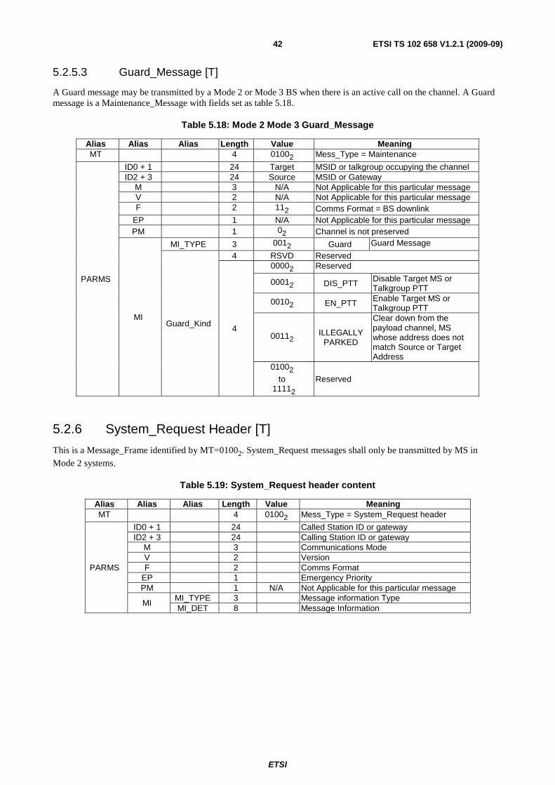
ETSI
ETSI TS 102 658 V1.2.1 (2009-09)42
5.2.5.3 Guard_Message [T]
A Guard message may be transmitted by a Mode 2 or Mode 3 BS when there is an active call on the channel. A Guard message is a Maintenance_Message with fields set as table 5.18.
Table 5.18: Mode 2 Mode 3 Guard_Message
Alias Alias Alias Length Value Meaning MT 4 01002 Mess_Type = Maintenance
PARMS
ID0 + 1 24 Target MSID or talkgroup occupying the channel ID2 + 3 24 Source MSID or Gateway
M 3 N/A Not Applicable for this particular message V 2 N/A Not Applicable for this particular message F 2 112 Comms Format = BS downlink
EP 1 N/A Not Applicable for this particular message PM 1 02 Channel is not preserved
MI
MI_TYPE 3 0012 Guard Guard Message
Guard_Kind
4 RSVD Reserved
4
00002 Reserved
00012 DIS_PTT Disable Target MS or Talkgroup PTT
00102 EN_PTT Enable Target MS or Talkgroup PTT
00112 ILLEGALLY PARKED
Clear down from the payload channel, MS whose address does not match Source or Target Address
01002
to 11112
Reserved
5.2.6 System_Request Header [T]
This is a Message_Frame identified by MT=01002. System_Request messages shall only be transmitted by MS in
Mode 2 systems.
Table 5.19: System_Request header content
Alias Alias Alias Length Value Meaning MT 4 01002 Mess_Type = System_Request header
PARMS
ID0 + 1 24 Called Station ID or gateway ID2 + 3 24 Calling Station ID or gateway
M 3 Communications Mode V 2 Version F 2 Comms Format
EP 1 Emergency Priority PM 1 N/A Not Applicable for this particular message
MI MI_TYPE 3 Message information Type MI_DET 8 Message Information
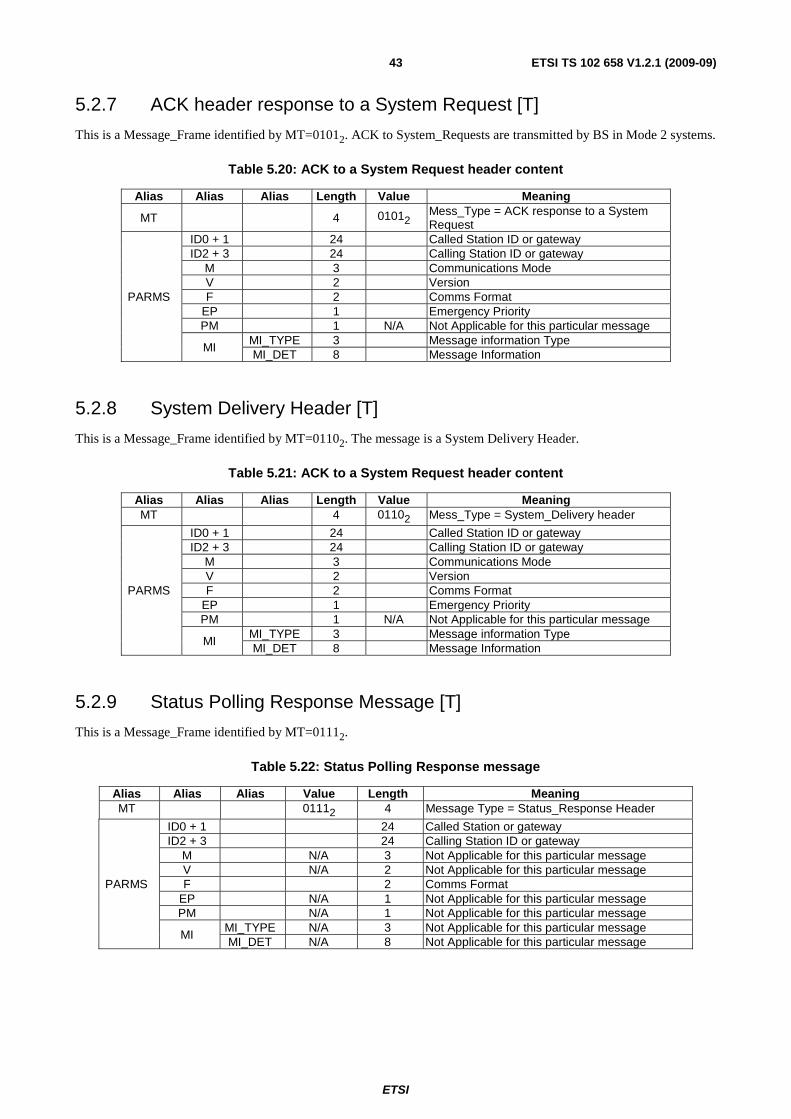
ETSI
ETSI TS 102 658 V1.2.1 (2009-09)43
5.2.7 ACK header response to a System Request [T]
This is a Message_Frame identified by MT=01012. ACK to System_Requests are transmitted by BS in Mode 2 systems.
Table 5.20: ACK to a System Request header content
Alias Alias Alias Length Value Meaning
MT 4 01012 Mess_Type = ACK response to a System Request
PARMS
ID0 + 1 24 Called Station ID or gateway ID2 + 3 24 Calling Station ID or gateway
M 3 Communications Mode V 2 Version F 2 Comms Format
EP 1 Emergency Priority PM 1 N/A Not Applicable for this particular message
MI MI_TYPE 3 Message information Type MI_DET 8 Message Information
5.2.8 System Delivery Header [T]
This is a Message_Frame identified by MT=01102. The message is a System Delivery Header.
Table 5.21: ACK to a System Request header content
Alias Alias Alias Length Value Meaning MT 4 01102 Mess_Type = System_Delivery header
PARMS
ID0 + 1 24 Called Station ID or gateway ID2 + 3 24 Calling Station ID or gateway
M 3 Communications Mode V 2 Version F 2 Comms Format
EP 1 Emergency Priority PM 1 N/A Not Applicable for this particular message
MI MI_TYPE 3 Message information Type MI_DET 8 Message Information
5.2.9 Status Polling Response Message [T]
This is a Message_Frame identified by MT=01112.
Table 5.22: Status Polling Response message
Alias Alias Alias Value Length Meaning MT 01112 4 Message Type = Status_Response Header
PARMS
ID0 + 1 24 Called Station or gateway ID2 + 3 24 Calling Station ID or gateway
M N/A 3 Not Applicable for this particular message V N/A 2 Not Applicable for this particular message F 2 Comms Format
EP N/A 1 Not Applicable for this particular message PM N/A 1 Not Applicable for this particular message
MI MI_TYPE N/A 3 Not Applicable for this particular message MI_DET N/A 8 Not Applicable for this particular message

ETSI
ETSI TS 102 658 V1.2.1 (2009-09)44
5.2.10 Status Polling Request Message [T]
This is a Message_Frame identified by MT=10002.
Table 5.23: Status Polling Request header
Alias Alias Alias Value Length Meaning MT 10012 4 Message Type = Status_Request Header
PARMS
ID0 + 1 24 Called Station or gateway ID2 + 3 24 Calling Station or gateway
M N/A 3 Not Applicable for this particular message V N/A 2 Not Applicable for this particular message F 2 Comms Format
EP N/A 1 Not Applicable for this particular message PM N/A 1 Not Applicable for this particular message
MI MI_TYPE N/A 3 Not Applicable for this particular message MI_DET N/A 8 Not Applicable for this particular message
5.2.11 BS_Command header(U) and response(D) [T]
This is a Message_Frame identified by MT=10012.
Table 5.23a
Alias Alias Alias Value Length Meaning
MT 10012 4 Message Type = BS_Command header and response
PARMS
ID0 + 1 24 Called Station or gateway ID2 + 3 24 Calling Station ID or gateway
M N/A 3 Not Applicable for this particular message V N/A 2 Not Applicable for this particular message F 2 Comms Format
EP N/A 1 Not Applicable for this particular message PM N/A 1 Not Applicable for this particular message
MI MI_TYPE N/A 3 Not Applicable for this particular message MI_DET N/A 8 Not Applicable for this particular message
5.2.12 BS_Access header(U) and response(D) [T]
This is a Message_Frame identified by MT=10102.
Table 5.23b
Alias Alias Alias Value Length Meaning
MT 10102 4 Message Type = BS_Access header and response
PARMS
ID0 + 1 24 Called Station or gateway ID2 + 3 24 Calling Station or gateway
M N/A 3 Not Applicable for this particular message V N/A 2 Not Applicable for this particular message F 2 Comms Format
EP N/A 1 Not Applicable for this particular message PM N/A 1 Not Applicable for this particular message
MI MI_TYPE
0002
3
No Appended_Data
0012 An Appended_Data message is concatenated to this header
other Reserved MI_DET N/A 8 Not Applicable for this particular message

ETSI
ETSI TS 102 658 V1.2.1 (2009-09)45
NOTE: The BS_Access response message transmitted by a BS may itself demand an acknowledgement.
5.2.13 Broadcast Messages [B] [T]
This is a Message_Frame transmitted by a BS and identified by MT=10112. These messages are unacknowledged. The
structure is illustrated in figure 5.5.
Real Time Clk
System Parms
Broadcasts
Alohas
Announcements
Call Timers
Vote Now
Tx with Mic open
Go to Channel
Individual
Group
Talkgroup
Move Chanmnel
Figure 5.5: Broadcast Structure
Broadcast messages are divided into the functionality of Aloha, Announcements, Move messages, Goto Channel messages, and Ambience listening activation messages, by the MI_TYPE field as illustrated in table 5.24.
Table 5.24: Types of Broadcast
Alias Length Value Meaning
MI_TYPE 3
0002 Broadcast = Aloha
0012 Broadcast = Announcement
0102 Broadcast = Move
0112 Broadcast = Goto_Channel
1002 Broadcast = Ambience Listening
1012 Reserved
1102 Reserved
1112 Reserved
5.2.13.1 Broadcast Aloha Message [B]
The Aloha message (B_ALOHA) is transmitted by a Mode3 BS to all MS or a sub-set of MS defined by the contents of the Aloha.

ETSI
ETSI TS 102 658 V1.2.1 (2009-09)46
Table 5.25: Aloha Message Content
Alias Alias Alias Length Value Meaning MT 4 10112 Message Type = Broadcast
PARMS
ID0 + 1 24 MS ID or DUMMYI SYS 14 System Identity Code
RSVD 10 10 × 02 Reserved
MASK 5 NRAND_WAIT 4 Wait between random access attempts
MI_TYPE 3 0002 Broadcast = Aloha
MI_DET
SF 2 Service_Function BACKOFF 4 Backoff Number for random access
ACTIVE 1 02 Radio site is isolated
12 Radio site is connected to the network
REG 1 02 Registration Not Required
12 Registration Required
5.2.13.2 Broadcast Announcements [B]
Announcements are transmitted by a Mode 3 BS to all MS or a sub-set of MS. Announcements are defined by MI_TYPE = 0012.
Table 5.26: Broadcast Announcements
Alias Alias Alias Alias length value Meaning MT 4 10012 Header type
PARMS
ANT 4
00002 Announcement Type = Timers
00012 Announcement Type = Vote Now
00102 Announcement Type = Mass Reg
00112 Announce Real Time
others Reserved ANNS 53 Announcement Parameters
MI
MI_TYPE 3 0012 Call Information = Announcement
MI_DET
RSVD 2 002 Reserved
BACKOFF 4 Backoff Number
ACTIVE 1 02 Radio site is isolated
12 Radio site is connected to the network
REG 1 02 Registration Not Required
12 Registration Required
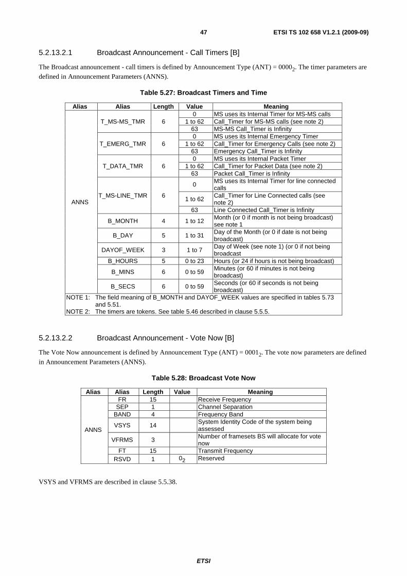
ETSI
ETSI TS 102 658 V1.2.1 (2009-09)47
5.2.13.2.1 Broadcast Announcement - Call Timers [B]
The Broadcast announcement - call timers is defined by Announcement Type (ANT) = 00002. The timer parameters are
defined in Announcement Parameters (ANNS).
Table 5.27: Broadcast Timers and Time
Alias Alias Length Value Meaning
ANNS
T_MS-MS_TMR 6 0 MS uses its Internal Timer for MS-MS calls
1 to 62 Call_Timer for MS-MS calls (see note 2) 63 MS-MS Call_Timer is Infinity
T_EMERG_TMR 6 0 MS uses its Internal Emergency Timer
1 to 62 Call_Timer for Emergency Calls (see note 2) 63 Emergency Call_Timer is Infinity
T_DATA_TMR 6 0 MS uses its Internal Packet Timer
1 to 62 Call_Timer for Packet Data (see note 2) 63 Packet Call_Timer is Infinity
T_MS-LINE_TMR 6
0 MS uses its Internal Timer for line connected calls
1 to 62 Call_Timer for Line Connected calls (see note 2)
63 Line Connected Call_Timer is Infinity
B_MONTH 4 1 to 12 Month (or 0 if month is not being broadcast) see note 1
B_DAY 5 1 to 31 Day of the Month (or 0 if date is not being broadcast)
DAYOF_WEEK 3 1 to 7 Day of Week (see note 1) (or 0 if not being broadcast
B_HOURS 5 0 to 23 Hours (or 24 if hours is not being broadcast)
B_MINS 6 0 to 59 Minutes (or 60 if minutes is not being broadcast)
B_SECS 6 0 to 59 Seconds (or 60 if seconds is not being broadcast)
NOTE 1: The field meaning of B_MONTH and DAYOF_WEEK values are specified in tables 5.73 and 5.51.
NOTE 2: The timers are tokens. See table 5.46 described in clause 5.5.5.
5.2.13.2.2 Broadcast Announcement - Vote Now [B]
The Vote Now announcement is defined by Announcement Type (ANT) = 00012. The vote now parameters are defined
in Announcement Parameters (ANNS).
Table 5.28: Broadcast Vote Now
Alias Alias Length Value Meaning
ANNS
FR 15 Receive Frequency SEP 1 Channel Separation
BAND 4 Frequency Band
VSYS 14 System Identity Code of the system being assessed
VFRMS 3 Number of framesets BS will allocate for vote now
FT 15 Transmit Frequency RSVD 1 02 Reserved
VSYS and VFRMS are described in clause 5.5.38.
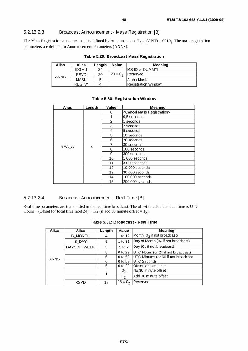
ETSI
ETSI TS 102 658 V1.2.1 (2009-09)48
5.2.13.2.3 Broadcast Announcement - Mass Registration [B]
The Mass Registration announcement is defined by Announcement Type (ANT) = 00102. The mass registration
parameters are defined in Announcement Parameters (ANNS).
Table 5.29: Broadcast Mass Registration
Alias Alias Length Value Meaning
ANNS
ID0 + 1 24 MS ID or DUMMYI RSVD 20 20 × 02 Reserved
MASK 5 Aloha Mask REG_W 4 Registration Window
Table 5.30: Registration Window
Alias Length Value Meaning
REG_W 4
0 <Cancel Mass Registration> 1 0,5 seconds 2 1 seconds 3 2 seconds 4 5 seconds 5 10 seconds 6 20 seconds 7 30 seconds 8 100 seconds 9 300 seconds 10 1 000 seconds 11 3 000 seconds 12 10 000 seconds 13 30 000 seconds 14 100 000 seconds 15 200 000 seconds
5.2.13.2.4 Broadcast Announcement - Real Time [B]
Real time parameters are transmitted in the real time broadcast. The offset to calculate local time is UTC Hours + (Offset for local time mod 24) + 1/2 (if add 30 minute offset = 12).
Table 5.31: Broadcast - Real Time
Alias Alias Length Value Meaning
ANNS
B_MONTH 4 1 to 12 Month (02 if not broadcast)
B_DAY 5 1 to 31 Day of Month (02 if not broadcast)
DAYSOF_WEEK 3 1 to 7 Day (02 if not broadcast)
5 0 to 23 UTC Hours (or 24 if not broadcast) 6 0 to 59 UTC Minutes (or 60 if not broadcast 6 0 to 59 UTC Seconds 5 0 to 23 Offset for local time
1 02 No 30 minute offset
12 Add 30 minute offset
RSVD 18 18 × 02 Reserved
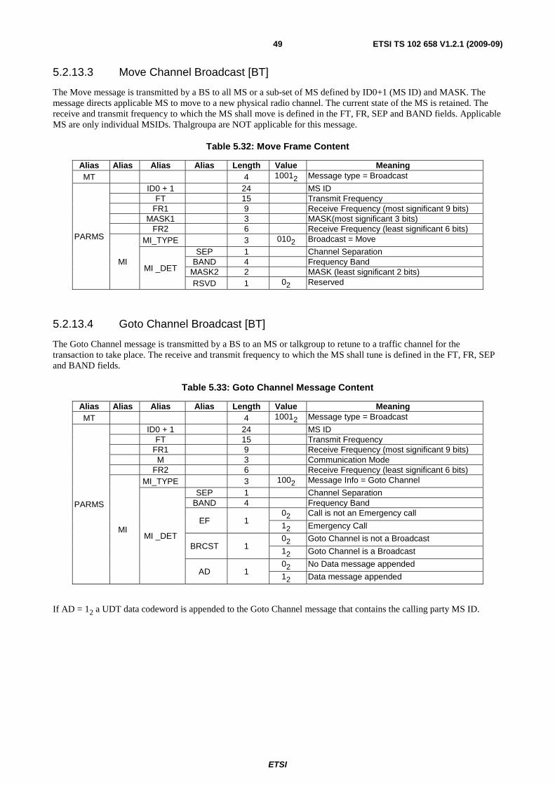
ETSI
ETSI TS 102 658 V1.2.1 (2009-09)49
5.2.13.3 Move Channel Broadcast [BT]
The Move message is transmitted by a BS to all MS or a sub-set of MS defined by ID0+1 (MS ID) and MASK. The message directs applicable MS to move to a new physical radio channel. The current state of the MS is retained. The receive and transmit frequency to which the MS shall move is defined in the FT, FR, SEP and BAND fields. Applicable MS are only individual MSIDs. Thalgroupa are NOT applicable for this message.
Table 5.32: Move Frame Content
Alias Alias Alias Alias Length Value Meaning MT 4 10012 Message type = Broadcast
PARMS
ID0 + 1 24 MS ID FT 15 Transmit Frequency FR1 9 Receive Frequency (most significant 9 bits) MASK1 3 MASK(most significant 3 bits) FR2 6 Receive Frequency (least significant 6 bits)
MI
MI_TYPE 3 0102 Broadcast = Move
MI _DET
SEP 1 Channel Separation BAND 4 Frequency Band
MASK2 2 MASK (least significant 2 bits) RSVD 1 02 Reserved
5.2.13.4 Goto Channel Broadcast [BT]
The Goto Channel message is transmitted by a BS to an MS or talkgroup to retune to a traffic channel for the transaction to take place. The receive and transmit frequency to which the MS shall tune is defined in the FT, FR, SEP and BAND fields.
Table 5.33: Goto Channel Message Content
Alias Alias Alias Alias Length Value Meaning MT 4 10012 Message type = Broadcast
PARMS
ID0 + 1 24 MS ID FT 15 Transmit Frequency FR1 9 Receive Frequency (most significant 9 bits) M 3 Communication Mode FR2 6 Receive Frequency (least significant 6 bits)
MI
MI_TYPE 3 1002 Message Info = Goto Channel
MI _DET
SEP 1 Channel Separation BAND 4 Frequency Band
EF 1 02 Call is not an Emergency call
12 Emergency Call
BRCST 1 02 Goto Channel is not a Broadcast
12 Goto Channel is a Broadcast
AD 1 02 No Data message appended
12 Data message appended
If AD = 12 a UDT data codeword is appended to the Goto Channel message that contains the calling party MS ID.
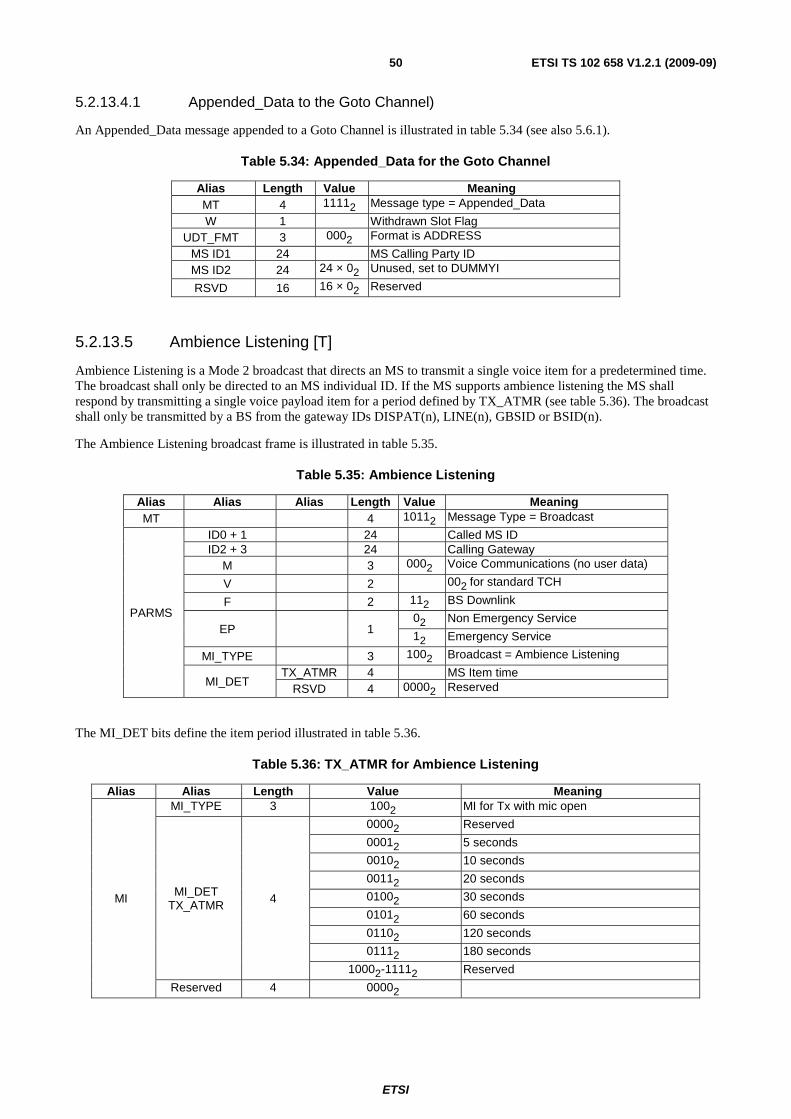
ETSI
ETSI TS 102 658 V1.2.1 (2009-09)50
5.2.13.4.1 Appended_Data to the Goto Channel)
An Appended_Data message appended to a Goto Channel is illustrated in table 5.34 (see also 5.6.1).
Table 5.34: Appended_Data for the Goto Channel
Alias Length Value Meaning MT 4 11112 Message type = Appended_Data
W 1 Withdrawn Slot Flag UDT_FMT 3 0002 Format is ADDRESS
MS ID1 24 MS Calling Party ID MS ID2 24 24 × 02 Unused, set to DUMMYI
RSVD 16 16 × 02 Reserved
5.2.13.5 Ambience Listening [T]
Ambience Listening is a Mode 2 broadcast that directs an MS to transmit a single voice item for a predetermined time. The broadcast shall only be directed to an MS individual ID. If the MS supports ambience listening the MS shall respond by transmitting a single voice payload item for a period defined by TX_ATMR (see table 5.36). The broadcast shall only be transmitted by a BS from the gateway IDs DISPAT(n), LINE(n), GBSID or BSID(n).
The Ambience Listening broadcast frame is illustrated in table 5.35.
Table 5.35: Ambience Listening
Alias Alias Alias Length Value Meaning MT 4 10112 Message Type = Broadcast
PARMS
ID0 + 1 24 Called MS ID ID2 + 3 24 Calling Gateway
M 3 0002 Voice Communications (no user data)
V 2 002 for standard TCH
F 2 112 BS Downlink
EP 1 02 Non Emergency Service
12 Emergency Service
MI_TYPE 3 1002 Broadcast = Ambience Listening
MI_DET TX_ATMR 4 MS Item time
RSVD 4 00002 Reserved
The MI_DET bits define the item period illustrated in table 5.36.
Table 5.36: TX_ATMR for Ambience Listening
Alias Alias Length Value Meaning
MI
MI_TYPE 3 1002 MI for Tx with mic open
MI_DET TX_ATMR 4
00002 Reserved
00012 5 seconds
00102 10 seconds
00112 20 seconds
01002 30 seconds
01012 60 seconds
01102 120 seconds
01112 180 seconds
10002-11112 Reserved
Reserved 4 00002
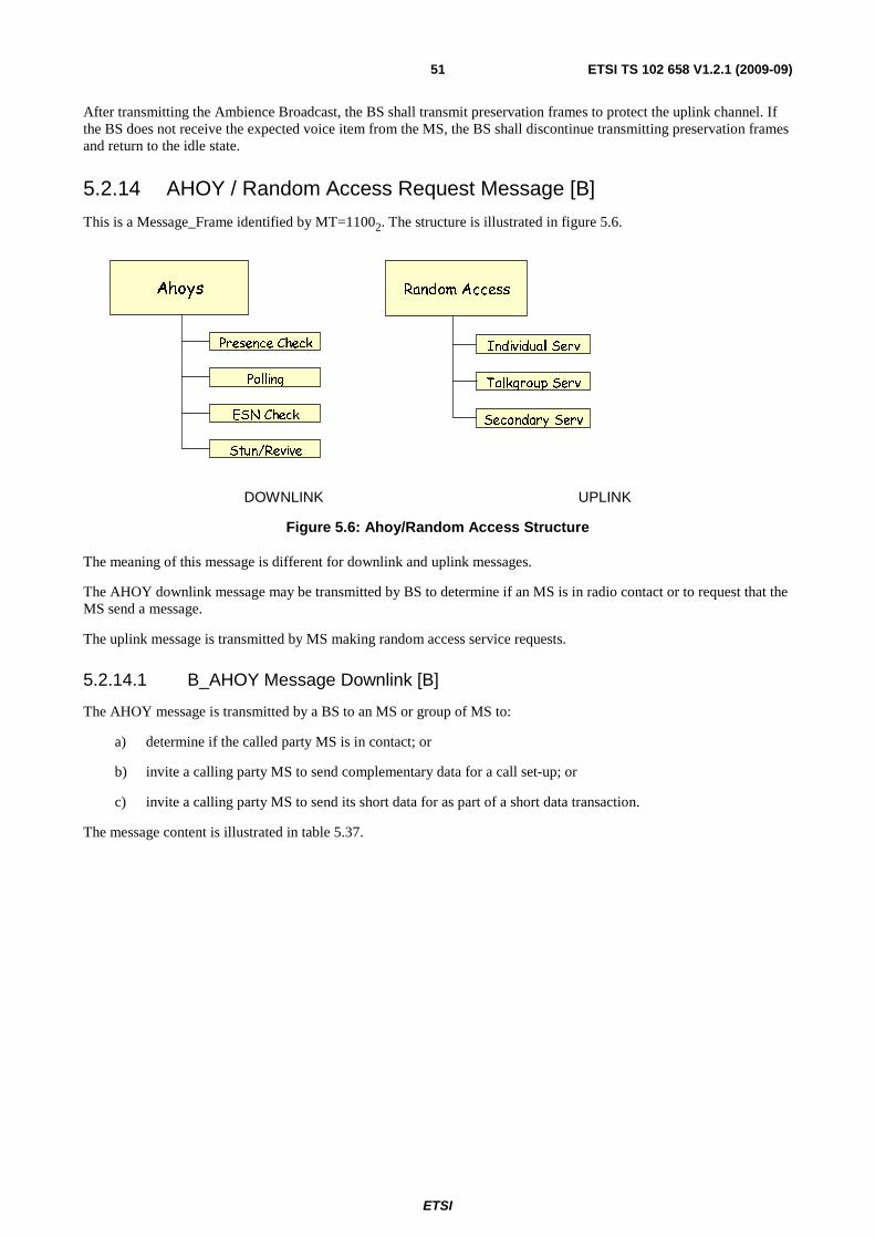
ETSI
ETSI TS 102 658 V1.2.1 (2009-09)51
After transmitting the Ambience Broadcast, the BS shall transmit preservation frames to protect the uplink channel. If the BS does not receive the expected voice item from the MS, the BS shall discontinue transmitting preservation frames and return to the idle state.
5.2.14 AHOY / Random Access Request Message [B]
This is a Message_Frame identified by MT=11002. The structure is illustrated in figure 5.6.
DOWNLINK UPLINK
Figure 5.6: Ahoy/Random Access Structure
The meaning of this message is different for downlink and uplink messages.
The AHOY downlink message may be transmitted by BS to determine if an MS is in radio contact or to request that the MS send a message.
The uplink message is transmitted by MS making random access service requests.
5.2.14.1 B_AHOY Message Downlink [B]
The AHOY message is transmitted by a BS to an MS or group of MS to:
a) determine if the called party MS is in contact; or
b) invite a calling party MS to send complementary data for a call set-up; or
c) invite a calling party MS to send its short data for as part of a short data transaction.
The message content is illustrated in table 5.37.
Ahoys
Polling
Presence Check
ESN Check
Stun/Revive
Random Access
Talkgroup Serv
Individual Serv
Secondary Serv
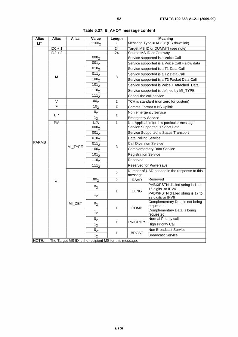
ETSI
ETSI TS 102 658 V1.2.1 (2009-09)52
Table 5.37: B_AHOY message content
Alias Alias Alias Value Length Meaning MT 11002 4 Message Type = AHOY (BS downlink)
PARMS
ID0 + 1 24 Target MS ID or DUMMYI (see note) ID2 + 3 24 Source MS ID or Gateway
M
0002
3
Service supported is a Voice Call 0012 Service supported is a Voice Call + slow data 0102 Service supported is a T1 Data Call 0112 Service supported is a T2 Data Call 1002 Service supported is a T3 Packet Data Call 1012 Service supported is Voice + Attached_Data 1102 Service supported is defined by MI_TYPE 1112 Cancel the call service
V 002 2 TCH is standard (non zero for custom) F 102 2 Comms Format = BS Uplink
EP 02
1 Non emergency service
12 Emergency Service PM N/A 1 Not Applicable for this particular message
MI
MI_TYPE
0002
3
Service Supported is Short Data
0012 Service Supported is Status Transport
0102 Data Polling Service
0112 Call Diversion Service
1002 Complementary Data Service
1012 Registration Service
1102 Reserved
1112 Reserved for Powersave
MI_DET
2 Number of UAD needed in the response to this message
002 2 RSVD Reserved
02 1 LONG
PABX/PSTN dialled string is 1 to 16 digits. or IPV4
12 PABX/PSTN dialled string is 17 to 32 digits or IPV6
02 1 COMP
Complementary Data is not being requested
12 Complementary Data is being requested
02 1 PRIORITY
Normal Priority call
12 High Priority Call
02 1 BRCST
Non Broadcast Service
12 Broadcast Service
NOTE: The Target MS ID is the recipient MS for this message.
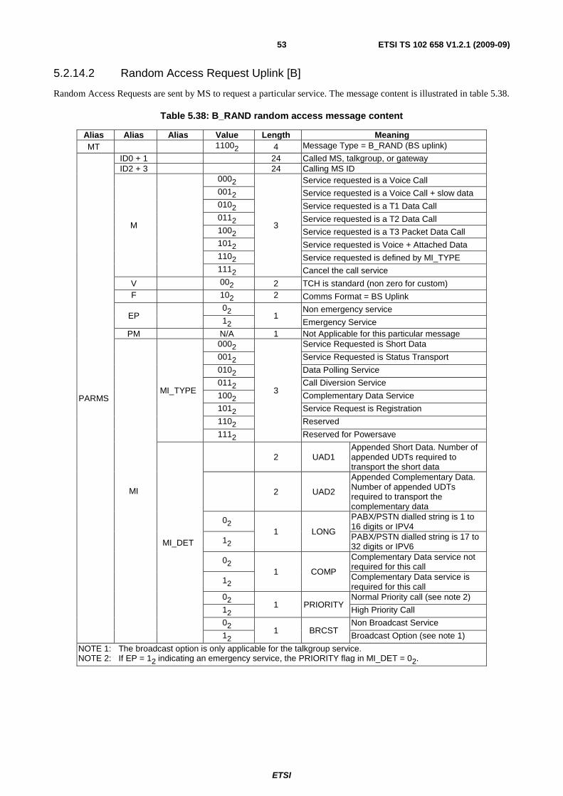
ETSI
ETSI TS 102 658 V1.2.1 (2009-09)53
5.2.14.2 Random Access Request Uplink [B]
Random Access Requests are sent by MS to request a particular service. The message content is illustrated in table 5.38.
Table 5.38: B_RAND random access message content
Alias Alias Alias Value Length Meaning MT 11002 4 Message Type = B_RAND (BS uplink)
PARMS
ID0 + 1 24 Called MS, talkgroup, or gateway ID2 + 3 24 Calling MS ID
M
0002
3
Service requested is a Voice Call 0012 Service requested is a Voice Call + slow data 0102 Service requested is a T1 Data Call 0112 Service requested is a T2 Data Call 1002 Service requested is a T3 Packet Data Call 1012 Service requested is Voice + Attached Data 1102 Service requested is defined by MI_TYPE 1112 Cancel the call service
V 002 2 TCH is standard (non zero for custom) F 102 2 Comms Format = BS Uplink
EP 02
1 Non emergency service
12 Emergency Service PM N/A 1 Not Applicable for this particular message
MI
MI_TYPE
0002
3
Service Requested is Short Data
0012 Service Requested is Status Transport
0102 Data Polling Service
0112 Call Diversion Service
1002 Complementary Data Service
1012 Service Request is Registration
1102 Reserved
1112 Reserved for Powersave
MI_DET
2 UAD1 Appended Short Data. Number of appended UDTs required to transport the short data
2 UAD2
Appended Complementary Data. Number of appended UDTs required to transport the complementary data
02 1 LONG
PABX/PSTN dialled string is 1 to 16 digits or IPV4
12 PABX/PSTN dialled string is 17 to 32 digits or IPV6
02 1 COMP
Complementary Data service not required for this call
12 Complementary Data service is required for this call
02 1 PRIORITY
Normal Priority call (see note 2)
12 High Priority Call
02 1 BRCST
Non Broadcast Service
12 Broadcast Option (see note 1)
NOTE 1: The broadcast option is only applicable for the talkgroup service. NOTE 2: If EP = 12 indicating an emergency service, the PRIORITY flag in MI_DET = 02.

ETSI
ETSI TS 102 658 V1.2.1 (2009-09)54
5.2.15 UDT Header messages [B]
This is a Message_Frame identified by MT=11102. The structure is illustrated in figure 5.7.
DOWNLINK UPLINK
Figure 5.7: UDT Header
UDT Header messages may be transmitted both on the uplink and downlink for Mode 3 systems. The message is illustrated in table 5.39. Between 1 and 4 Appended_Data messages may be concatenated to the UDT header. The number of UDT Appended_Data Messages is indicated by the Appended_Data (UAD) field. The format of the data carried in the Appended_Data messages is defined in UDT_FORMAT. If this UDT header + Appended_Data is carrying user data (short data) and the short data is formatted BCD, 7 bit, or 8 bit, the SYMB field contains the number of user symbols in the Appended_Data (see note).
NOTE: If the number of symbols = 64, SYMB = 00 00002.
Supplementary Data
Uplink Extended Address
Short Data Message
Individual
Talkgroup
All Call
Uplink Data
Uplink Dial Digits
Unified Data UploadUnified Data
Download
Short Data Message
Supplementary Data
CLI
System message
Emergency
Individual
Group
All
Call Diversion
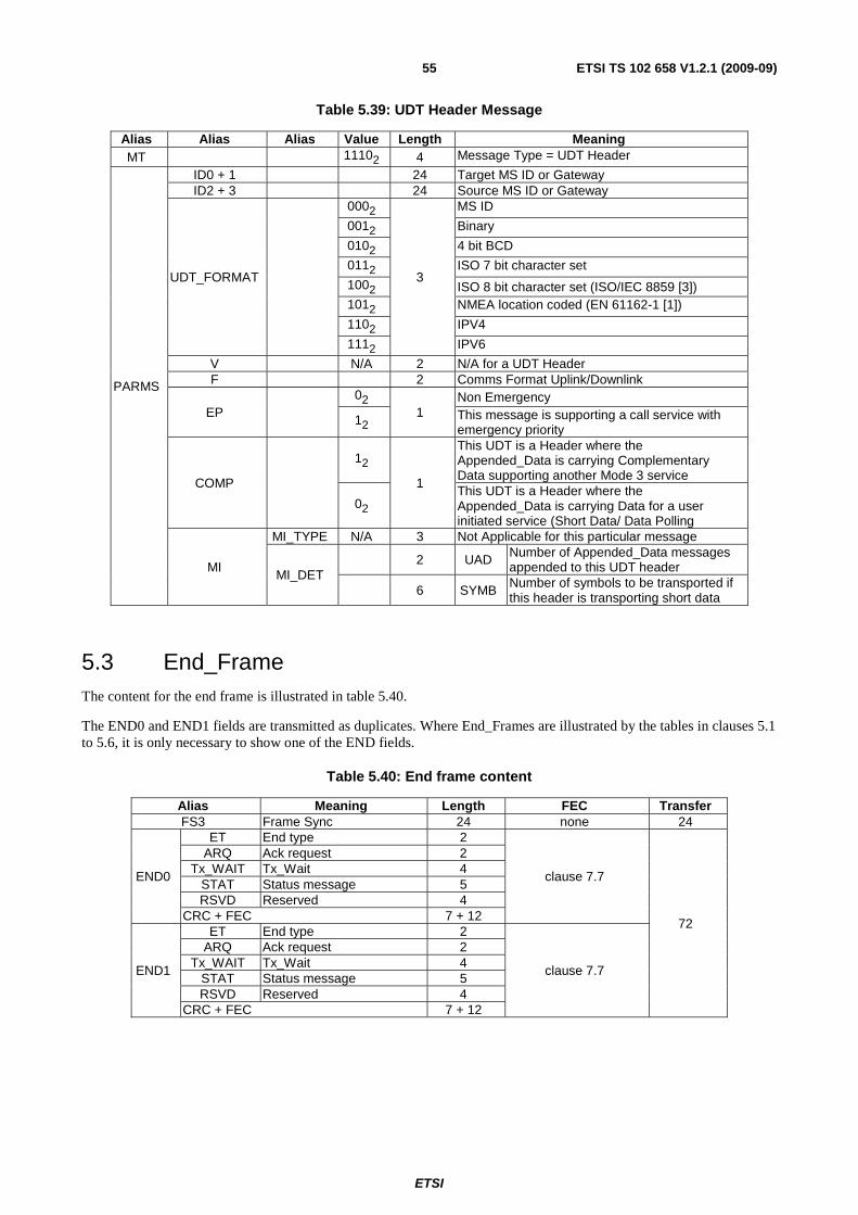
ETSI
ETSI TS 102 658 V1.2.1 (2009-09)55
Table 5.39: UDT Header Message
Alias Alias Alias Value Length Meaning MT 11102 4 Message Type = UDT Header
PARMS
ID0 + 1 24 Target MS ID or Gateway ID2 + 3 24 Source MS ID or Gateway
UDT_FORMAT
0002
3
MS ID
0012 Binary
0102 4 bit BCD
0112 ISO 7 bit character set
1002 ISO 8 bit character set (ISO/IEC 8859 [3]) 1012 NMEA location coded (EN 61162-1 [1])
1102 IPV4
1112 IPV6
V N/A 2 N/A for a UDT Header F 2 Comms Format Uplink/Downlink
EP 02
1 Non Emergency
12 This message is supporting a call service with emergency priority
COMP
12
1
This UDT is a Header where the Appended_Data is carrying Complementary Data supporting another Mode 3 service
02 This UDT is a Header where the Appended_Data is carrying Data for a user initiated service (Short Data/ Data Polling
MI
MI_TYPE N/A 3 Not Applicable for this particular message
MI_DET 2 UAD Number of Appended_Data messages
appended to this UDT header
6 SYMB Number of symbols to be transported if this header is transporting short data
5.3 End_Frame The content for the end frame is illustrated in table 5.40.
The END0 and END1 fields are transmitted as duplicates. Where End_Frames are illustrated by the tables in clauses 5.1 to 5.6, it is only necessary to show one of the END fields.
Table 5.40: End frame content
Alias Meaning Length FEC Transfer FS3 Frame Sync 24 none 24
END0
ET End type 2
clause 7.7
72
ARQ Ack request 2 Tx_WAIT Tx_Wait 4
STAT Status message 5 RSVD Reserved 4
CRC + FEC 7 + 12
END1
ET End type 2
clause 7.7
ARQ Ack request 2 Tx_WAIT Tx_Wait 4
STAT Status message 5 RSVD Reserved 4
CRC + FEC 7 + 12
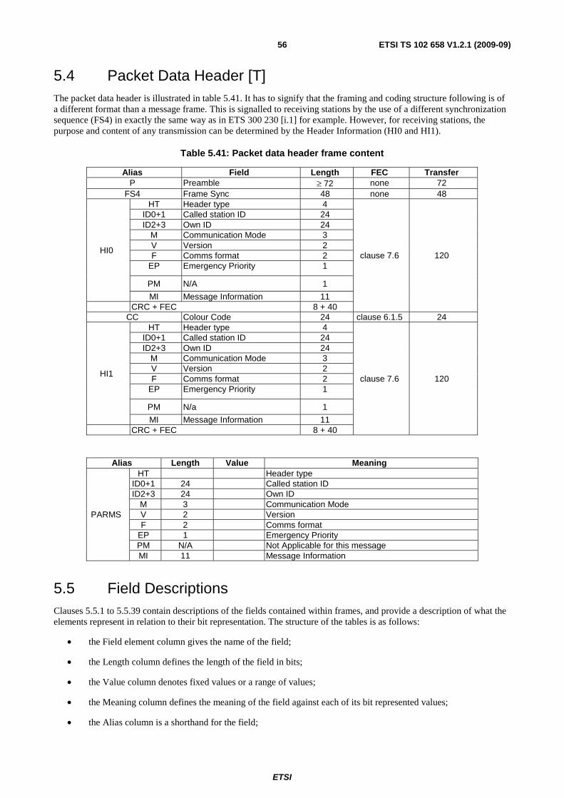
ETSI
ETSI TS 102 658 V1.2.1 (2009-09)56
5.4 Packet Data Header [T] The packet data header is illustrated in table 5.41. It has to signify that the framing and coding structure following is of a different format than a message frame. This is signalled to receiving stations by the use of a different synchronization sequence (FS4) in exactly the same way as in ETS 300 230 [i.1] for example. However, for receiving stations, the purpose and content of any transmission can be determined by the Header Information (HI0 and HI1).
Table 5.41: Packet data header frame content
Alias Field Length FEC Transfer P Preamble ≥ 72 none 72
FS4 Frame Sync 48 none 48
HI0
HT Header type 4
clause 7.6 120
ID0+1 Called station ID 24 ID2+3 Own ID 24
M Communication Mode 3 V Version 2 F Comms format 2
EP Emergency Priority 1
PM N/A 1
MI Message Information 11 CRC + FEC 8 + 40
CC Colour Code 24 clause 6.1.5 24
HI1
HT Header type 4
clause 7.6 120
ID0+1 Called station ID 24 ID2+3 Own ID 24
M Communication Mode 3 V Version 2 F Comms format 2
EP Emergency Priority 1
PM N/a 1
MI Message Information 11 CRC + FEC 8 + 40
Alias Length Value Meaning
PARMS
HT Header type ID0+1 24 Called station ID ID2+3 24 Own ID
M 3 Communication Mode V 2 Version F 2 Comms format
EP 1 Emergency Priority PM N/A Not Applicable for this message MI 11 Message Information
5.5 Field Descriptions Clauses 5.5.1 to 5.5.39 contain descriptions of the fields contained within frames, and provide a description of what the elements represent in relation to their bit representation. The structure of the tables is as follows:
• the Field element column gives the name of the field;
• the Length column defines the length of the field in bits;
• the Value column denotes fixed values or a range of values;
• the Meaning column defines the meaning of the field against each of its bit represented values;
• the Alias column is a shorthand for the field;

ETSI
ETSI TS 102 658 V1.2.1 (2009-09)57
• the Mnemonic is a description of the particular value of a field or alias.
5.5.1 Active ACTIVE [B]
On a BS downlink channel, the active field indicates if the radio site is isolated from the network or has an active connection to the network.
Table 5.42: Active Field
Alias Length Value Meaning
ACTIVE 1 02 The radio site BS is isolated from the network
12 The radio site is connected to the network
5.5.2 Appended_ Data [BT]
If the Complementary Data Service has been invoked as an option with other voice or data services, the Appended Complementary Data field is used to pass the number of Appended_Data UDTs needed to upload the Complementary Data.
If the Short Data Service has been invoked, the Appended Short Data field is used by an MS to pass the number of Appended_Data UDTs needed to upload the Short Data.
Table 5.43: Appended Complementary Data field
Field Length Alias Value Meaning
Appended_Data 2 UAD
002 Number of Appended_Data UDTs needed to transfer the data = 1
012 Number of Appended_Data UDTs needed to transfer the data = 2
102 Number of Appended_Data UDTs needed to transfer the data = 3
112 Number of Appended_Data UDTs needed to transfer the data = 4
5.5.3 ARQ [T]
Table 5.44 describes the ARQ field. This field is part of an END frame.
Table 5.44: ARQ
Alias Length Value Meaning
ARQ 2
002 No ACK request to called station
012 ACK request to called station
102 Reserved
112 Reserved

ETSI
ETSI TS 102 658 V1.2.1 (2009-09)58
5.5.4 Backoff [B]
The Backoff field is illustrated in table 5.45.
Table 5.45: Backoff Number
Alias Length Value Meaning
BACKOFF 4
0 0 - Reserved 1 Backoff Frameset length = 1 2 Backoff Frameset length = 2 3 Backoff Frameset length = 3 4 Backoff Frameset length = 4 5 Backoff Frameset length = 5 6 Backoff Frameset length = 8 7 Backoff Frameset length = 11 8 Backoff Frameset length = 15 9 Backoff Frameset length = 20 10 Backoff Frameset length = 26 11 Backoff Frameset length = 33 12 Backoff Frameset length = 41 13 Backoff Frameset length = 50 14 Backoff Frameset length = 70 15 Backoff Frameset length = 100
5.5.5 Call Timers [BT]
The Call timers specified in this clause use tokens to extend the real time Values from what could be expressed using a purely binary representation.
Table 5.46: Call Timer Tokens
Alias Value Length Meaning
T_MS-MS
T_EMERG_T
T_PACKET
T_MS-LINE
0
6
MS uses its Internal Timers for the appropriate call type
1 to 10 Call_Timer in seconds
11 to 20 Call timer in increments of 5 seconds from - 11 = 15 seconds to 20 = 60 seconds
21 to 18 Call timer in increments of 15 seconds from - 11 = 75 seconds to 20 = 180 seconds
19 to 31 Call timer in increments of 30 seconds from - 19 = 3 minutes to 31 = 9 minutes
32 to 42 Call timer in increments of 1 minute from - 32 = 10 minutes to 42 = 19 minutes
43 to 62 Call timer in increments of 5 minutes from - 43 = 20 minutes to 42 = 115 minutes
63 Call timer is infinity
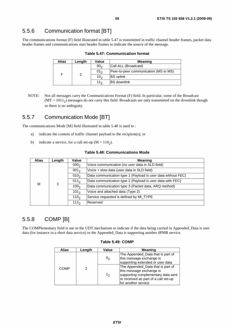
ETSI
ETSI TS 102 658 V1.2.1 (2009-09)59
5.5.6 Communication format [BT]
The communications format [F] field illustrated in table 5.47 is transmitted in traffic channel header frames, packet data header frames and communications start header frames to indicate the source of the message.
Table 5.47: Communication format
Alias Length Value Meaning
F 2
002 Call ALL (Broadcast)
012 Peer-to-peer communication (MS to MS)
102 BS uplink
112 BS downlink
NOTE: Not all messages carry the Communications Format (F) field. In particular, some of the Broadcast (MT = 10112) messages do not carry this field. Broadcasts are only transmitted on the downlink though
so there is no ambiguity.
5.5.7 Communication Mode [BT]
The communications Mode [M] field illustrated in table 5.48 is used to :
a) indicate the content of traffic channel payload to the recipient(s); or
b) indicate a service, for a call set-up (M = 1102).
Table 5.48: Communications Mode
Alias Length Value Meaning
M 3
0002 Voice communication (no user data in SLD field)
0012 Voice + slow data (user data in SLD field)
0102 Data communication type 1 (Payload is user data without FEC)
0112 Data communication type 2 (Payload is user data with FEC)
1002 Data communication type 3 (Packet data, ARQ method)
1012 Voice and attached data (Type 2)
1102 Service requested is defined by MI_TYPE
1112 Reserved
5.5.8 COMP [B]
The COMPlementary field is use in the UDT mechanism to indicate if the data being carried in Appended_Data is user data (for instance in a short data service) or the Appended_Data is supporting another dPMR service.
Table 5.49: COMP
Alias Length Value Meaning
COMP 2
02 The Appended_Data that is part of this message exchange is supporting extended or user data
12
The Appended_Data that is part of this message exchange is supporting complementary data sent or received as part of a call set-up for another service
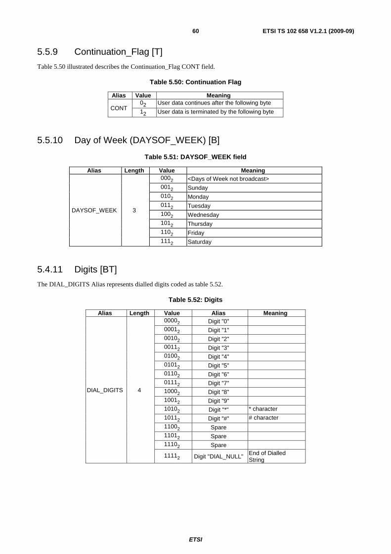
ETSI
ETSI TS 102 658 V1.2.1 (2009-09)60
5.5.9 Continuation_Flag [T]
Table 5.50 illustrated describes the Continuation_Flag CONT field.
Table 5.50: Continuation Flag
Alias Value Meaning
CONT 02 User data continues after the following byte
12 User data is terminated by the following byte
5.5.10 Day of Week (DAYSOF_WEEK) [B]
Table 5.51: DAYSOF_WEEK field
Alias Length Value Meaning
DAYSOF_WEEK 3
0002 <Days of Week not broadcast> 0012 Sunday 0102 Monday 0112 Tuesday 1002 Wednesday 1012 Thursday 1102 Friday 1112 Saturday
5.4.11 Digits [BT]
The DIAL_DIGITS Alias represents dialled digits coded as table 5.52.
Table 5.52: Digits
Alias Length Value Alias Meaning
DIAL_DIGITS 4
00002 Digit "0"
00012 Digit "1"
00102 Digit "2"
00112 Digit "3"
01002 Digit "4"
01012 Digit "5"
01102 Digit "6"
01112 Digit "7"
10002 Digit "8"
10012 Digit "9"
10102 Digit "*" * character
10112 Digit "#" # character
11002 Spare
11012 Spare
11102 Spare
11112 Digit "DIAL_NULL" End of Dialled String

ETSI
ETSI TS 102 658 V1.2.1 (2009-09)61
If dialled digits are transported between entities as part of a PABX or PSTN call setup the number of dialled digits shall be determined as follows:
• The sending entity shall fill unused BCD digits in the Appended_Data message(s) with DIAL_NULL (11112).
• The receiving entity shall then count the dialled digits until DIAL_NULL is encountered.
5.5.12 Emergency Priority [BT]
The emergency priority [EP] field illustrated in table 5.53 is transmitted in traffic channel header frames, packet data header frames and communications start header frames to indicate if the call has emergency priority.
Table 5.53: Priority
Alias Length Value Meaning
EP 1 02 Normal Priority
12 Emergency Priority
5.5.13 End_Type [T]
Table 5.54 illustrated below describes the End_Type field. This field is part of an END frame.
Table 5.54: End type
Alias Length Value Meaning
ET 2
002 Normal end frame
012 End frame with status message
102 Reserved
112 Reserved
5.5.14 Frame numbering [T]
The frame numbering field illustrated in table 5.55 is used in traffic channel superframes to indicate the particular superframe being transmitted.
Table 5.55: Frame numbering
Alias Length Value meaning
FN 2
002 frame 1 012 frame 2 102 frame 3 112 frame 4
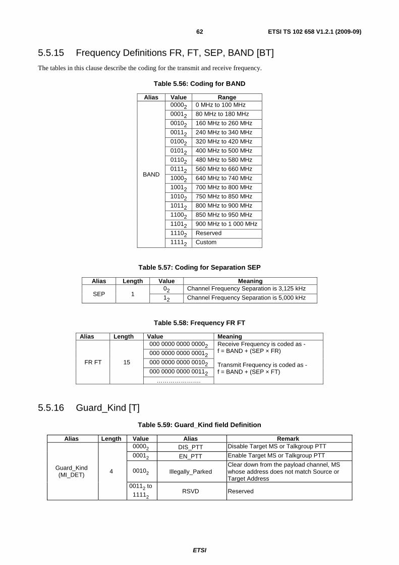
ETSI
ETSI TS 102 658 V1.2.1 (2009-09)62
5.5.15 Frequency Definitions FR, FT, SEP, BAND [BT]
The tables in this clause describe the coding for the transmit and receive frequency.
Table 5.56: Coding for BAND
Alias Value Range
BAND
00002 0 MHz to 100 MHz
00012 80 MHz to 180 MHz
00102 160 MHz to 260 MHz
00112 240 MHz to 340 MHz
01002 320 MHz to 420 MHz
01012 400 MHz to 500 MHz
01102 480 MHz to 580 MHz
01112 560 MHz to 660 MHz
10002 640 MHz to 740 MHz
10012 700 MHz to 800 MHz
10102 750 MHz to 850 MHz
10112 800 MHz to 900 MHz
11002 850 MHz to 950 MHz
11012 900 MHz to 1 000 MHz
11102 Reserved
11112 Custom
Table 5.57: Coding for Separation SEP
Alias Length Value Meaning
SEP 1 02 Channel Frequency Separation is 3,125 kHz
12 Channel Frequency Separation is 5,000 kHz
Table 5.58: Frequency FR FT
Alias Length Value Meaning
FR FT 15
000 0000 0000 00002 Receive Frequency is coded as - f = BAND + (SEP × FR) Transmit Frequency is coded as - f = BAND + (SEP × FT)
000 0000 0000 00012
000 0000 0000 00102
000 0000 0000 00112
………………….
5.5.16 Guard_Kind [T]
Table 5.59: Guard_Kind field Definition
Alias Length Value Alias Remark
Guard_Kind (MI_DET)
4
00002 DIS_PTT Disable Target MS or Talkgroup PTT
00012 EN_PTT Enable Target MS or Talkgroup PTT
00102 Illegally_Parked Clear down from the payload channel, MS whose address does not match Source or Target Address
00112 to 11112 RSVD Reserved
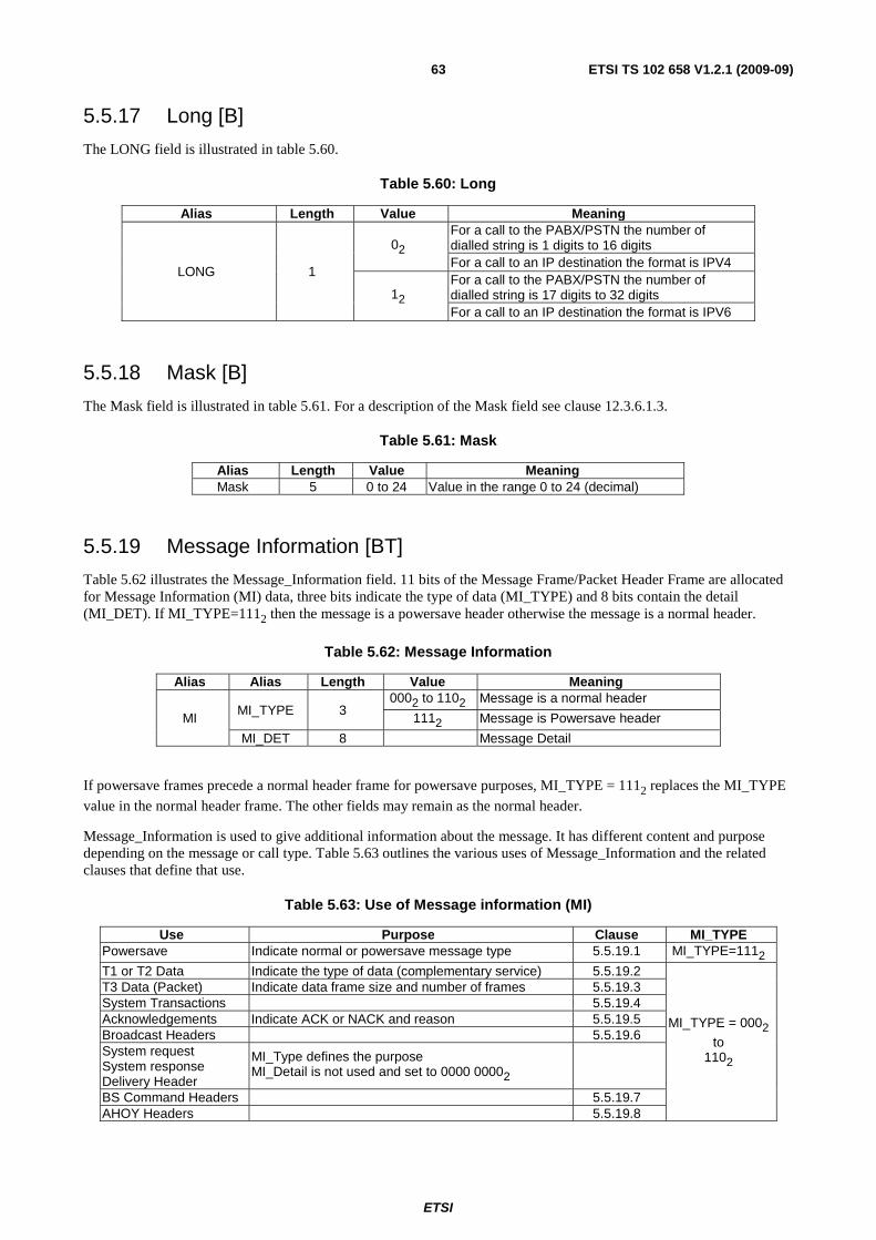
ETSI
ETSI TS 102 658 V1.2.1 (2009-09)63
5.5.17 Long [B]
The LONG field is illustrated in table 5.60.
Table 5.60: Long
Alias Length Value Meaning
LONG 1
02 For a call to the PABX/PSTN the number of dialled string is 1 digits to 16 digits For a call to an IP destination the format is IPV4
12 For a call to the PABX/PSTN the number of dialled string is 17 digits to 32 digits For a call to an IP destination the format is IPV6
5.5.18 Mask [B]
The Mask field is illustrated in table 5.61. For a description of the Mask field see clause 12.3.6.1.3.
Table 5.61: Mask
Alias Length Value Meaning Mask 5 0 to 24 Value in the range 0 to 24 (decimal)
5.5.19 Message Information [BT]
Table 5.62 illustrates the Message_Information field. 11 bits of the Message Frame/Packet Header Frame are allocated for Message Information (MI) data, three bits indicate the type of data (MI_TYPE) and 8 bits contain the detail (MI_DET). If MI_TYPE=1112 then the message is a powersave header otherwise the message is a normal header.
Table 5.62: Message Information
Alias Alias Length Value Meaning
MI MI_TYPE 3
0002 to 1102 Message is a normal header
1112 Message is Powersave header
MI_DET 8 Message Detail
If powersave frames precede a normal header frame for powersave purposes, MI_TYPE = 1112 replaces the MI_TYPE
value in the normal header frame. The other fields may remain as the normal header.
Message_Information is used to give additional information about the message. It has different content and purpose depending on the message or call type. Table 5.63 outlines the various uses of Message_Information and the related clauses that define that use.
Table 5.63: Use of Message information (MI)
Use Purpose Clause MI_TYPE Powersave Indicate normal or powersave message type 5.5.19.1 MI_TYPE=1112
T1 or T2 Data Indicate the type of data (complementary service) 5.5.19.2
MI_TYPE = 0002
to 1102
T3 Data (Packet) Indicate data frame size and number of frames 5.5.19.3 System Transactions 5.5.19.4 Acknowledgements Indicate ACK or NACK and reason 5.5.19.5 Broadcast Headers 5.5.19.6 System request System response Delivery Header
MI_Type defines the purpose MI_Detail is not used and set to 0000 00002
BS Command Headers 5.5.19.7 AHOY Headers 5.5.19.8

ETSI
ETSI TS 102 658 V1.2.1 (2009-09)64
5.5.19.1 Message Information for Powersave [T]
Powersave messages are only transmitted by Mode 1 MS and Mode 2 MS/BS.
For powersave wake-up headers, the WU bits indicate how many (powersave-1) frames follow the current one (i.e. counting down to zero).
Table 5.64: MI bits for powersave
Alias Alias Length Value Meaning
MI
MI_TYPE 3 1112 Powersave header
RSVD 4 00002 Reserved
WU 4
11112
-- ↓ -- 00012
Extended Header frame 15 Extended Header frame 1
00002 Normal header frame
5.5.19.2 Message Information for Types 1 and 2 data [T]
Message Information bits for type 1 and 2 data is illustrated in table 5.65.
Table 5.65: MI bits for type 1 and 2 data
Alias Alias Length Value Meaning
MI
MI_TYPE 3 0012 MI for Types 1 and 2 data
TFormat 4
00002 Status message
00012 Pre-coded message
00102 Free text message (radio generated data)
00112 Short file transfer
01002 User defined data 1
01012 User defined data 2
01102 User defined data 3
01112 User defined data 4
10002 to11112 Reserved
Reserved 4 00002
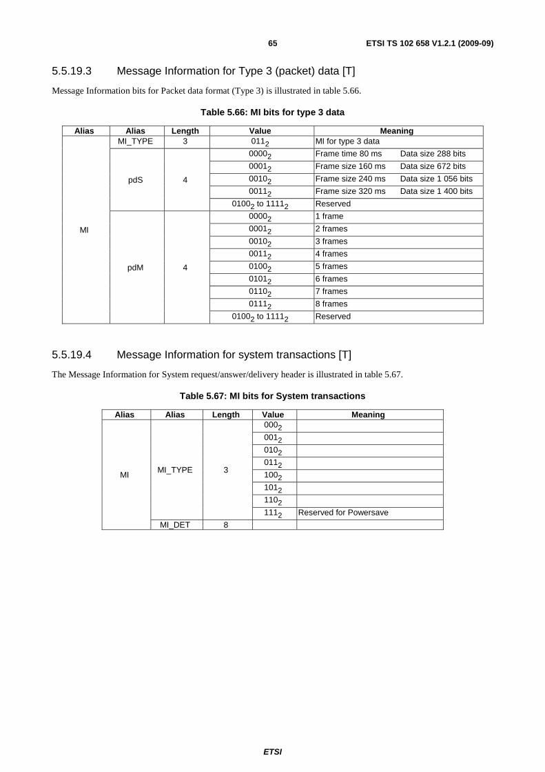
ETSI
ETSI TS 102 658 V1.2.1 (2009-09)65
5.5.19.3 Message Information for Type 3 (packet) data [T]
Message Information bits for Packet data format (Type 3) is illustrated in table 5.66.
Table 5.66: MI bits for type 3 data
Alias Alias Length Value Meaning
MI
MI_TYPE 3 0112 MI for type 3 data
pdS 4
00002 Frame time 80 ms Data size 288 bits
00012 Frame size 160 ms Data size 672 bits
00102 Frame size 240 ms Data size 1 056 bits
00112 Frame size 320 ms Data size 1 400 bits
01002 to 11112 Reserved
pdM 4
00002 1 frame
00012 2 frames
00102 3 frames
00112 4 frames
01002 5 frames
01012 6 frames
01102 7 frames
01112 8 frames
01002 to 11112 Reserved
5.5.19.4 Message Information for system transactions [T]
The Message Information for System request/answer/delivery header is illustrated in table 5.67.
Table 5.67: MI bits for System transactions
Alias Alias Length Value Meaning
MI MI_TYPE 3
0002
0012
0102
0112
1002
1012
1102
1112 Reserved for Powersave
MI_DET 8
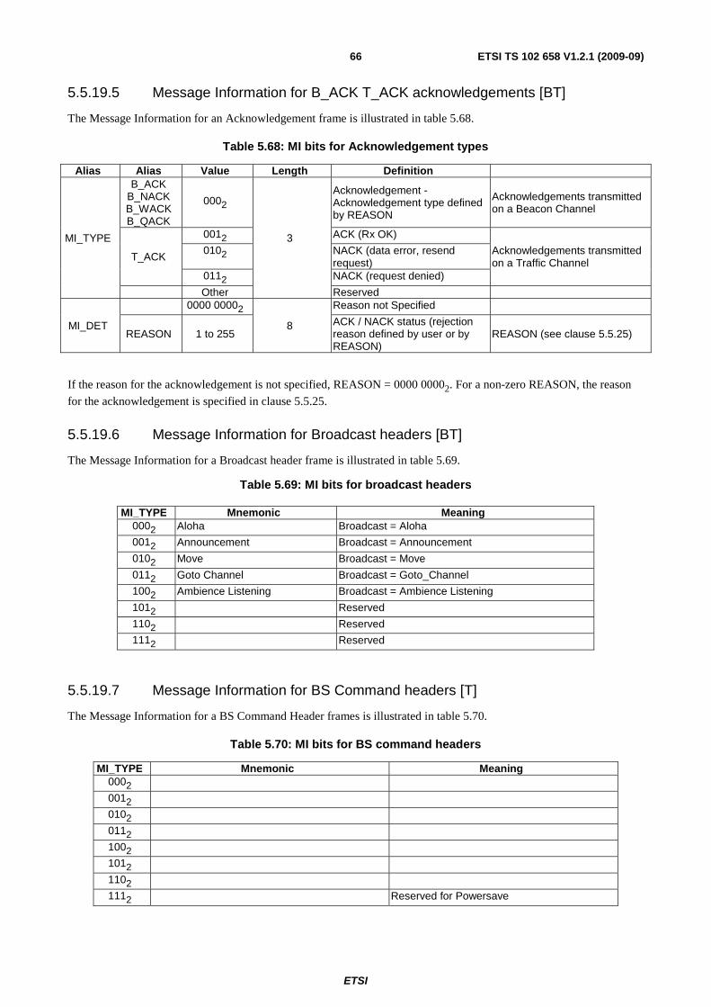
ETSI
ETSI TS 102 658 V1.2.1 (2009-09)66
5.5.19.5 Message Information for B_ACK T_ACK acknowledgements [BT]
The Message Information for an Acknowledgement frame is illustrated in table 5.68.
Table 5.68: MI bits for Acknowledgement types
Alias Alias Value Length Definition
MI_TYPE
B_ACK B_NACK B_WACK B_QACK
0002
3
Acknowledgement - Acknowledgement type defined by REASON
Acknowledgements transmitted on a Beacon Channel
T_ACK
0012 ACK (Rx OK)
Acknowledgements transmitted on a Traffic Channel
0102 NACK (data error, resend request)
0112 NACK (request denied)
Other Reserved
MI_DET
0000 00002
8
Reason not Specified
REASON 1 to 255 ACK / NACK status (rejection reason defined by user or by REASON)
REASON (see clause 5.5.25)
If the reason for the acknowledgement is not specified, REASON = 0000 00002. For a non-zero REASON, the reason
for the acknowledgement is specified in clause 5.5.25.
5.5.19.6 Message Information for Broadcast headers [BT]
The Message Information for a Broadcast header frame is illustrated in table 5.69.
Table 5.69: MI bits for broadcast headers
MI_TYPE Mnemonic Meaning 0002 Aloha Broadcast = Aloha
0012 Announcement Broadcast = Announcement
0102 Move Broadcast = Move
0112 Goto Channel Broadcast = Goto_Channel
1002 Ambience Listening Broadcast = Ambience Listening
1012 Reserved
1102 Reserved
1112 Reserved
5.5.19.7 Message Information for BS Command headers [T]
The Message Information for a BS Command Header frames is illustrated in table 5.70.
Table 5.70: MI bits for BS command headers
MI_TYPE Mnemonic Meaning 0002
0012
0102
0112
1002
1012
1102
1112 Reserved for Powersave

ETSI
ETSI TS 102 658 V1.2.1 (2009-09)67
Table 5.71: MI bits for Tech status requests
Alias Alias Length Value Meaning
MI
MI_TYPE 3 0002
MI_DET Parameter 3
0002
0012
0102
0112
1002
1012 to 1112
Reserved 5 000002
5.5.19.8 Message Information for additional services [B]
The Message Information for additional Beacon frames that cannot be described by the M field is illustrated in table 5.72.
Therefore the M field and the MI_TYPE field combine to fully define the service. If M = 1102 then table 5.72 applies.
Table 5.72: MI bits for B_AHOY Header Frames
MI_TYPE Mnemonic Meaning 0002 Short Data Service Requested is Short Data
0012 Status Transport Service Requested is Status Transport
0102 Data Polling Data Polling Service
0112 Call Diversion Call Diversion Service
1002 Complementary Service Complementary Service
1012 Registration or authentication Service Registration or authentication Service
1102 Reserved Reserved
1112 Powersave Reserved for Powersave
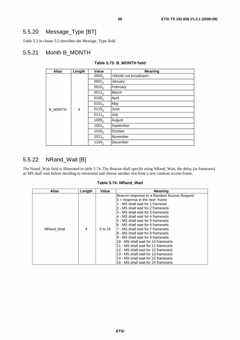
ETSI
ETSI TS 102 658 V1.2.1 (2009-09)68
5.5.20 Message_Type [BT]
Table 5.3 in clause 5.2 describes the Message_Type field.
5.5.21 Month B_MONTH
Table 5.73: B_MONTH field
Alias Length Value Meaning
B_MONTH 4
00002 <Month not broadcast>
00012 January
00102 February
00112 March
01002 April
01012 May
01102 June
01112 July
10002 August
10012 September
10102 October
10112 November
11002 December
5.5.22 NRand_Wait [B]
The Nrand_Wait field is illustrated in table 5.74. The Beacon shall specify using NRand_Wait, the delay (in framesets) an MS shall wait before deciding to retransmit and choose another slot from a new random-access-frame.
Table 5.74: NRand_Wait
Alias Length Value Meaning
NRand_Wait 4 0 to 15
Beacon response to a Random Access Request 0 = response in the next -frame 1 - MS shall wait for 1 frameset 2 - MS shall wait for 2 framesets 3 - MS shall wait for 3 framesets 4 - MS shall wait for 4 framesets 5 - MS shall wait for 5 framesets 6 - MS shall wait for 6 framesets 7 - MS shall wait for 7 framesets 8 - MS shall wait for 8 framesets 9 - MS shall wait for 9 framesets 10 - MS shall wait for 10 framesets 11 - MS shall wait for 11 framesets 12 - MS shall wait for 12 framesets 13 - MS shall wait for 13 framesets 14 - MS shall wait for 15 framesets 15 - MS shall wait for 24 framesets
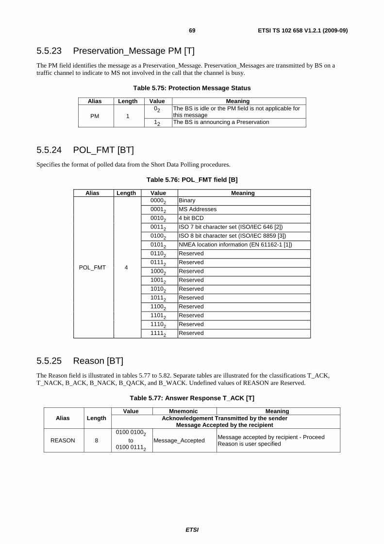
ETSI
ETSI TS 102 658 V1.2.1 (2009-09)69
5.5.23 Preservation_Message PM [T]
The PM field identifies the message as a Preservation_Message. Preservation_Messages are transmitted by BS on a traffic channel to indicate to MS not involved in the call that the channel is busy.
Table 5.75: Protection Message Status
Alias Length Value Meaning
PM 1 02 The BS is idle or the PM field is not applicable for
this message 12 The BS is announcing a Preservation
5.5.24 POL_FMT [BT]
Specifies the format of polled data from the Short Data Polling procedures.
Table 5.76: POL_FMT field [B]
Alias Length Value Meaning
POL_FMT 4
00002 Binary
00012 MS Addresses
00102 4 bit BCD
00112 ISO 7 bit character set (ISO/IEC 646 [2])
01002 ISO 8 bit character set (ISO/IEC 8859 [3])
01012 NMEA location information (EN 61162-1 [1])
01102 Reserved
01112 Reserved
10002 Reserved
10012 Reserved
10102 Reserved
10112 Reserved
11002 Reserved
11012 Reserved
11102 Reserved
11112 Reserved
5.5.25 Reason [BT]
The Reason field is illustrated in tables 5.77 to 5.82. Separate tables are illustrated for the classifications T_ACK, T_NACK, B_ACK, B_NACK, B_QACK, and B_WACK. Undefined values of REASON are Reserved.
Table 5.77: Answer Response T_ACK [T]
Alias Length Value Mnemonic Meaning
Acknowledgement Transmitted by the sender Message Accepted by the recipient
REASON 8
0100 01002
to 0100 01112
Message_Accepted Message accepted by recipient - Proceed Reason is user specified
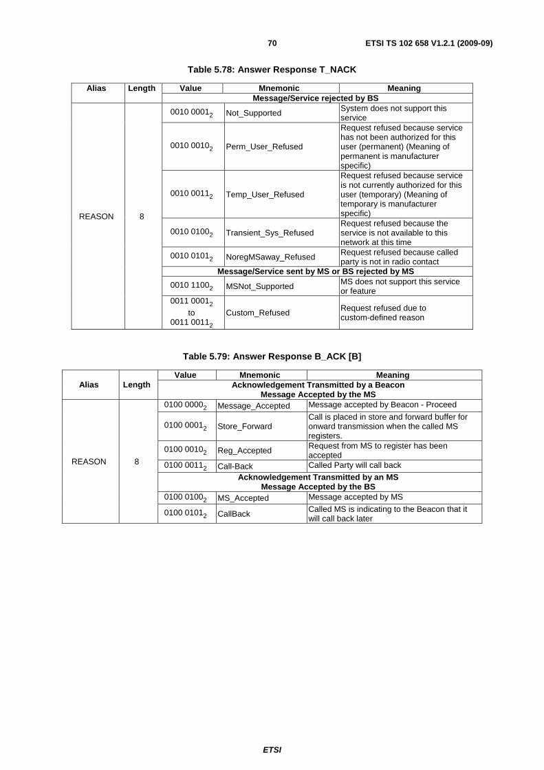
ETSI
ETSI TS 102 658 V1.2.1 (2009-09)70
Table 5.78: Answer Response T_NACK
Alias Length Value Mnemonic Meaning Message/Service rejected by BS
REASON 8
0010 00012 Not_Supported System does not support this service
0010 00102 Perm_User_Refused
Request refused because service has not been authorized for this user (permanent) (Meaning of permanent is manufacturer specific)
0010 00112 Temp_User_Refused
Request refused because service is not currently authorized for this user (temporary) (Meaning of temporary is manufacturer specific)
0010 01002 Transient_Sys_Refused Request refused because the service is not available to this network at this time
0010 01012 NoregMSaway_Refused Request refused because called party is not in radio contact
Message/Service sent by MS or BS rejected by MS
0010 11002 MSNot_Supported MS does not support this service or feature
0011 00012
to 0011 00112
Custom_Refused Request refused due to custom-defined reason
Table 5.79: Answer Response B_ACK [B]
Alias Length Value Mnemonic Meaning
Acknowledgement Transmitted by a Beacon Message Accepted by the MS
REASON 8
0100 00002 Message_Accepted Message accepted by Beacon - Proceed
0100 00012 Store_Forward Call is placed in store and forward buffer for onward transmission when the called MS registers.
0100 00102 Reg_Accepted Request from MS to register has been accepted
0100 00112 Call-Back Called Party will call back
Acknowledgement Transmitted by an MS Message Accepted by the BS
0100 01002 MS_Accepted Message accepted by MS
0100 01012 CallBack Called MS is indicating to the Beacon that it will call back later

ETSI
ETSI TS 102 658 V1.2.1 (2009-09)71
Table 5.80: Answer Response B_NACK
Alias Length Value Mnemonic Meaning Message/Service rejected by network (BS)
REASON 8
0010 00012 Not_Supported Network does not support this service
0010 00102 Perm_User_Refused
Request refused because service has not been authorized for this user (permanent) (Meaning of permanent is manufacturer specific)
0010 00112 Temp_User_Refused
Request refused because service is not currently authorized for this user (temporary) (Meaning of temporary is manufacturer specific)
0010 01002 Transient_Sys_Refused Request refused because the service is not available to this network at this time
0010 01012 NoregMSaway_Refused Request refused because called party is not in radio contact (and is not registered with the network)
0010 01102 MSaway_Refused Request refused because called party is not in radio contact (but is registered with the network)
0010 01112 Div_Cause_Fail Call cannot be processed because the MS has diverted its calls
0010 10002 SYSbusy_Refused Request refused because the network is experiencing congestion (Network Overload)
0010 10012 SYS_NotReady Request refused because the network is not ready (try later)
0010 10102 Call_Cancel_Refused Request to cancel a call has been refused i.e. the call may still mature
0010 10112 Reg_Refused Request from an MS to register has been refused
0010 11002 Reg_Denied Request from an MS to register has been denied
0010 11012 IP_Connection_failed Request from an MS to inform IP connection advice failed
Message/Service rejected by MS
0010 11002 MSNot_Supported MS does not support this service or feature
0010 11012 LineNot_Supported Request refused because service is not supported by the called party (Line)
0010 11102 StackFull_Refused Request refused because the called party's internal call stack is full and is not employing a FIFO
0010 11112 EuipBusy_Refused Request refused because called party ancillary equipment is busy
0011 00002 Recipient_Refused Request refused by called party user (like in FOACSU)
0011 00012 Custom_Refused Request refused due to custom-defined reason
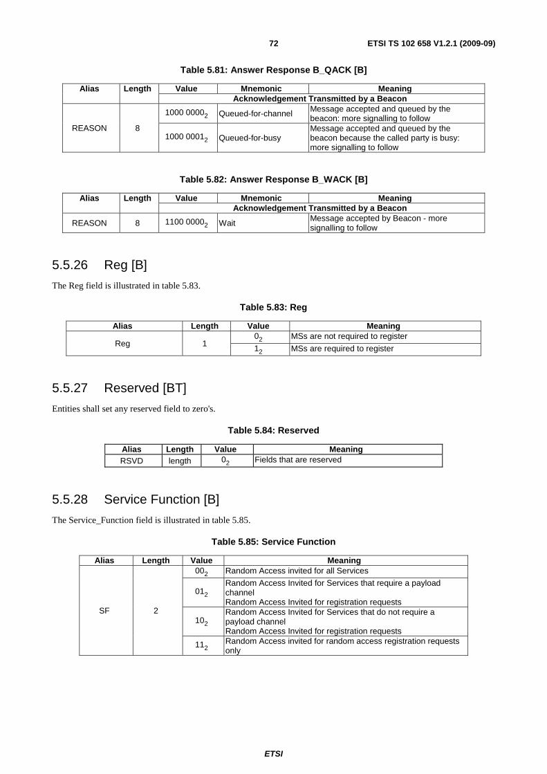
ETSI
ETSI TS 102 658 V1.2.1 (2009-09)72
Table 5.81: Answer Response B_QACK [B]
Alias Length Value Mnemonic Meaning Acknowledgement Transmitted by a Beacon
REASON 8
1000 00002 Queued-for-channel Message accepted and queued by the beacon: more signalling to follow
1000 00012 Queued-for-busy Message accepted and queued by the beacon because the called party is busy: more signalling to follow
Table 5.82: Answer Response B_WACK [B]
Alias Length Value Mnemonic Meaning Acknowledgement Transmitted by a Beacon
REASON 8 1100 00002 Wait Message accepted by Beacon - more signalling to follow
5.5.26 Reg [B]
The Reg field is illustrated in table 5.83.
Table 5.83: Reg
Alias Length Value Meaning
Reg 1 02 MSs are not required to register
12 MSs are required to register
5.5.27 Reserved [BT]
Entities shall set any reserved field to zero's.
Table 5.84: Reserved
Alias Length Value Meaning RSVD length 02 Fields that are reserved
5.5.28 Service Function [B]
The Service_Function field is illustrated in table 5.85.
Table 5.85: Service Function
Alias Length Value Meaning
SF 2
002 Random Access invited for all Services
012 Random Access Invited for Services that require a payload channel Random Access Invited for registration requests
102 Random Access Invited for Services that do not require a payload channel Random Access Invited for registration requests
112 Random Access invited for random access registration requests only
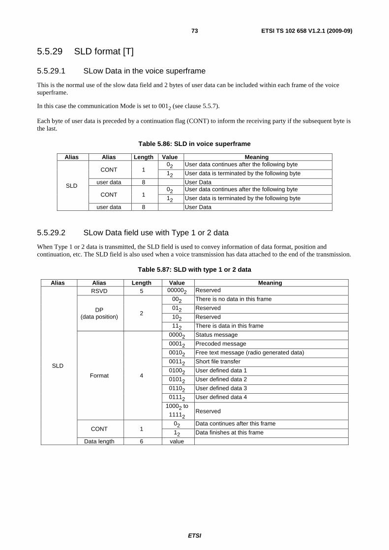
ETSI
ETSI TS 102 658 V1.2.1 (2009-09)73
5.5.29 SLD format [T]
5.5.29.1 SLow Data in the voice superframe
This is the normal use of the slow data field and 2 bytes of user data can be included within each frame of the voice superframe.
In this case the communication Mode is set to 0012 (see clause 5.5.7).
Each byte of user data is preceded by a continuation flag (CONT) to inform the receiving party if the subsequent byte is the last.
Table 5.86: SLD in voice superframe
Alias Alias Length Value Meaning
SLD
CONT 1 02 User data continues after the following byte
12 User data is terminated by the following byte
user data 8 User Data
CONT 1 02 User data continues after the following byte
12 User data is terminated by the following byte
user data 8 User Data
5.5.29.2 SLow Data field use with Type 1 or 2 data
When Type 1 or 2 data is transmitted, the SLD field is used to convey information of data format, position and continuation, etc. The SLD field is also used when a voice transmission has data attached to the end of the transmission.
Table 5.87: SLD with type 1 or 2 data
Alias Alias Length Value Meaning
SLD
RSVD 5 000002 Reserved
DP (data position)
2
002 There is no data in this frame
012 Reserved
102 Reserved
112 There is data in this frame
Format 4
00002 Status message
00012 Precoded message
00102 Free text message (radio generated data)
00112 Short file transfer
01002 User defined data 1
01012 User defined data 2
01102 User defined data 3
01112 User defined data 4
10002 to
11112 Reserved
CONT 1 02 Data continues after this frame
12 Data finishes at this frame
Data length 6 value
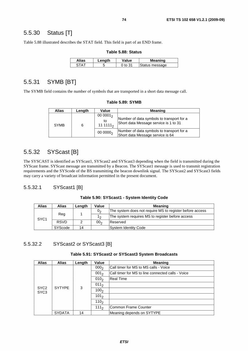
ETSI
ETSI TS 102 658 V1.2.1 (2009-09)74
5.5.30 Status [T]
Table 5.88 illustrated describes the STAT field. This field is part of an END frame.
Table 5.88: Status
Alias Length Value Meaning STAT 5 0 to 31 Status message
5.5.31 SYMB [BT]
The SYMB field contains the number of symbols that are transported in a short data message call.
Table 5.89: SYMB
Alias Length Value Meaning
SYMB 6
00 00012
to 11 11112
Number of data symbols to transport for a Short data Message service is 1 to 31
00 00002 Number of data symbols to transport for a Short data Message service is 64
5.5.32 SYScast [B]
The SYSCAST is identified as SYScast1, SYScast2 and SYScast3 depending when the field is transmitted during the SYScast frame. SYScast message are transmitted by a Beacon. The SYScast1 message is used to transmit registration requirements and the SYScode of the BS transmitting the beacon downlink signal. The SYScast2 and SYScast3 fields may carry a variety of broadcast information permitted in the present document.
5.5.32.1 SYScast1 [B]
Table 5.90: SYScast1 - System Identity Code
Alias Alias Length Value Meaning
SYC1 Reg 1
02 The system does not require MS to register before access
12 The system requires MS to register before access
RSVD 2 002 Reserved
SYScode 14 System Identity Code
5.5.32.2 SYScast2 or SYScast3 [B]
Table 5.91: SYScast2 or SYScast3 System Broadcasts
Alias Alias Length Value Meaning
SYC2 SYC3
SYTYPE 3
0002 Call timer for MS to MS calls - Voice
0012 Call timer for MS to line connected calls - Voice
0102 Real Time
0112
1002
1012
1102
1112 Common Frame Counter
SYDATA 14 Meaning depends on SYTYPE

ETSI
ETSI TS 102 658 V1.2.1 (2009-09)75
5.5.32.2.1 SYScast2 or SYScast3 Call Timer MS to MS [B]
Table 5.92: SYScast2 or SYScast3 Call timer 1
Alias Alias Alias Length Value Meaning
SYC2 SYC3
SYTYPE 3 0002 Call_Timer for MS to MS connected voice calls
RSVD 2 002 Reserved
SYDATA
T_MS-MS_TMR 6 0 MS uses its Internal Timer for MS-MS calls
1 to 62 Call_Timer for MS-MS calls (see note) 63 MS-MS Call_Timer is Infinity
T_EMERG_T 6 0 MS uses its Internal Emergency Timer
1 to 62 Call_Timer for Emergency Calls (see note) 63 Emergency Call_Timer is Infinity
NOTE: The values are tokens that are translated to real time by the table 5.46 described in clause 5.5.5.
5.5.32.2.2 Call Timer for line connected calls and packet data [B]
Table 5.93: SYScast2 or SYScast3 call timer 2
Alias Alias Alias Length Value Meaning
SYC2 SYC3
SYTYPE 3 0012 Call_Timer for Packet, and Line connected voice calls
RSVD 2 002 Reserved
SYDATA
T_DATA_TMR 6 0 MS uses its Internal Packet Timer
1 to 62 Call_Timer for Packet Data (see note) 63 Packet Call_Timer is Infinity
T_MS-LINE_TMR 6 0 MS uses its Internal Timer for line connected
calls 1 to 62 Call_Timer for Line Connected calls (see note)
63 Line Connected Call_Timer is Infinity NOTE: The values are tokens that are translated to real time by the table 5.46 described in clause 5.5.5.
5.5.32.2.3 SYScast2 or SYScast3 Real Time [B]
Table 5.94 illustrates how a beacon may synchronize MS clocks. There are not enough bits in this message to transmit the full UTC time and date. The message is split by the RTFMT field. If RTFMT = 02 then day of week and UTC hours
is broadcast. Designers may which to transmit this message only occasionally. If RTFMT = 12 the UTC hours and
minutes are broadcast.
Table 5.94: SYScast2 or SYScast3 real time
Alias Alias Alias Length Value Meaning
SYC2 SYC3
SYTYPE 3 0102 Real Time
SYDATA
RTFMT 1 02
5 0 00002 Reserved
DAYSOF_WEEK 3 0 to 7 Day of Week (see table 5.51)
5 0 to 23 UTC hours (or 60 if not broadcast)
Alias Alias Alias Length Value Meaning
SYC2 SYC3
SYTYPE 3 0102 Real Time
SYDATA
RTFMT 1 12
1 02 Reserved
6 0 to 59 UTC minutes (or 60 if not broadcast)
6 0 to 59 UTC seconds (or 60 if not broadcast)
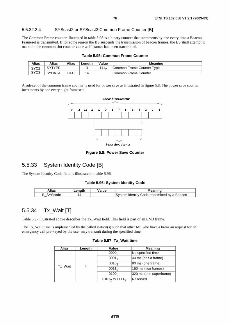
ETSI
ETSI TS 102 658 V1.2.1 (2009-09)76
5.5.32.2.4 SYScast2 or SYScast3 Common Frame Counter [B]
The Common Frame counter illustrated in table 5.95 is a binary counter that increments by one every time a Beacon Frameset is transmitted. If for some reason the BS suspends the transmission of beacon frames, the BS shall attempt to maintain the common slot counter value as if frames had been transmitted.
Table 5.95: Common Frame Counter
Alias Alias Alias Length Value Meaning SYC2 SYC3
SYTYPE 3 1112 Common Frame Counter Type
SYDATA CFC 14 Common Frame Counter
A sub-set of the common frame counter is used for power save as illustrated in figure 5.8. The power save counter increments by one every eight framesets.
12345678910111214 13
Common Frame Counter
Power Save Counter
Figure 5.8: Power Save Counter
5.5.33 System Identity Code [B]
The System Identity Code field is illustrated in table 5.96.
Table 5.96: System Identity Code
Alias Length Value Meaning B_SYScode 14 System identity Code transmitted by a Beacon
5.5.34 Tx_Wait [T]
Table 5.97 illustrated above describes the Tx_Wait field. This field is part of an END frame.
The Tx_Wait time is implemented by the called station(s) such that other MS who have a break-in request for an emergency call pre-keyed by the user may transmit during the specified time.
Table 5.97: Tx_Wait time
Alias Length Value Meaning
Tx_Wait 4
00002 No specified time
00012 40 ms (half a frame)
00102 80 ms (one frame)
00112 160 ms (two frames)
01002 320 ms (one superframe)
01012 to 11112 Reserved

ETSI
ETSI TS 102 658 V1.2.1 (2009-09)77
5.5.35 UAD [BT]
The UAD is a field in bursts that have Appended_Data concatenated to a message frame. The field indicates the number of Appended_Data messages in the burst.
Table 5.98: UAD field
Alias Length Value Meaning
UAD 2
002 One Appended_Data message
012 Two Appended_Data messages
102 Three Appended_Data messages
112 Four Appended_Data messages
5.5.36 UDT_Format [BT]
Specifies the format of the user or complementary data carried in UDT Header frames for the UDT mechanism.
Table 5.99: UDT_Format field
Alias Length Value Meaning
UDT_FORMAT 3
0002 MS ID 0012 Binary 0102 4 bit BCD 0112 ISO 7 bit character set (ISO/IEC 646 ( [2]) 1002 ISO 8 bit character set (ISO/IEC 8859 [3]) 1012 NMEA location coded (EN 61162-1 [1]) 1102 IPV4 1112 IPV6
NOTE: If the Appended_Data message is carrying PABX or PTSN dialled digits, there is no necessity for a specific field that indicates the number of dialled digits. The sender marks the end of the dialled string by a DIAL_NULL symbol (11112).
5.5.37 Version [BT]
The version [V] field illustrated in table 5.100 is transmitted in traffic channel header frames, packet data header frames and communications start header frames to indicate if the payload is dPMR standard traffic channel content.
Table 5.100: Version
Alias Length Value Meaning
V 2
002 Standard TCH content
012 TBD
102 TBD
112 Manufacturer Specific
5.5.38 Vote Now Advice Parameters [B]
Table 5.101: Vote Now Advice Parameters
Alias Length Value Meaning VSYS 14 System Identity Code of the beacon being assessed
VFRMS 5 Number of framesets BS will allocate for vote now
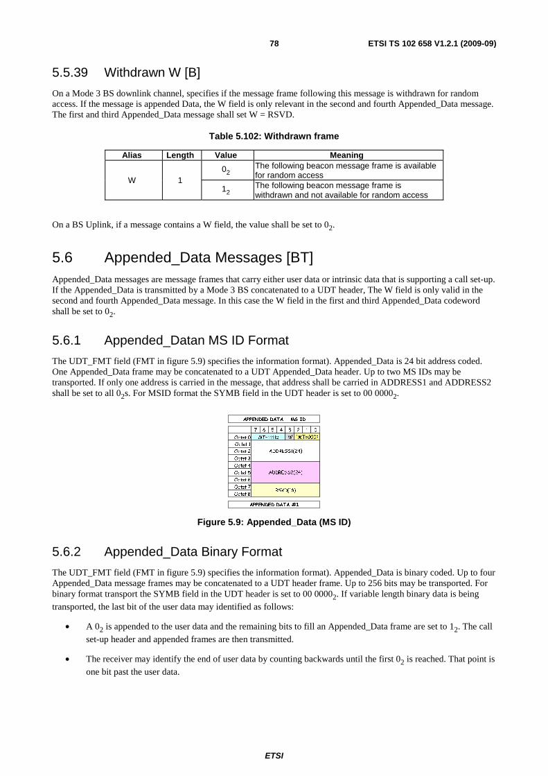
ETSI
ETSI TS 102 658 V1.2.1 (2009-09)78
5.5.39 Withdrawn W [B]
On a Mode 3 BS downlink channel, specifies if the message frame following this message is withdrawn for random access. If the message is appended Data, the W field is only relevant in the second and fourth Appended_Data message. The first and third Appended_Data message shall set W = RSVD.
Table 5.102: Withdrawn frame
Alias Length Value Meaning
W 1 02 The following beacon message frame is available
for random access
12 The following beacon message frame is withdrawn and not available for random access
On a BS Uplink, if a message contains a W field, the value shall be set to 02.
5.6 Appended_Data Messages [BT] Appended_Data messages are message frames that carry either user data or intrinsic data that is supporting a call set-up. If the Appended_Data is transmitted by a Mode 3 BS concatenated to a UDT header, The W field is only valid in the second and fourth Appended_Data message. In this case the W field in the first and third Appended_Data codeword shall be set to 02.
5.6.1 Appended_Datan MS ID Format
The UDT_FMT field (FMT in figure 5.9) specifies the information format). Appended_Data is 24 bit address coded. One Appended_Data frame may be concatenated to a UDT Appended_Data header. Up to two MS IDs may be transported. If only one address is carried in the message, that address shall be carried in ADDRESS1 and ADDRESS2 shall be set to all 02s. For MSID format the SYMB field in the UDT header is set to 00 00002.
APPENDED DATA #1
7 6 5 4 3 2 1 0
Octet 0
Octet 1
Octet 2
Octet 3
Octet 4
Octet 5
Octet 6
Octet 7
Octet 8
APPENDED DATA - MS ID
RSVD(16)
ADDRESS2(24)
ADDRESS1(24)
MT=11112 FMT=0002W
Figure 5.9: Appended_Data (MS ID)
5.6.2 Appended_Data Binary Format
The UDT_FMT field (FMT in figure 5.9) specifies the information format). Appended_Data is binary coded. Up to four Appended_Data message frames may be concatenated to a UDT header frame. Up to 256 bits may be transported. For binary format transport the SYMB field in the UDT header is set to 00 00002. If variable length binary data is being
transported, the last bit of the user data may identified as follows:
• A 02 is appended to the user data and the remaining bits to fill an Appended_Data frame are set to 12. The call
set-up header and appended frames are then transmitted.
• The receiver may identify the end of user data by counting backwards until the first 02 is reached. That point is
one bit past the user data.
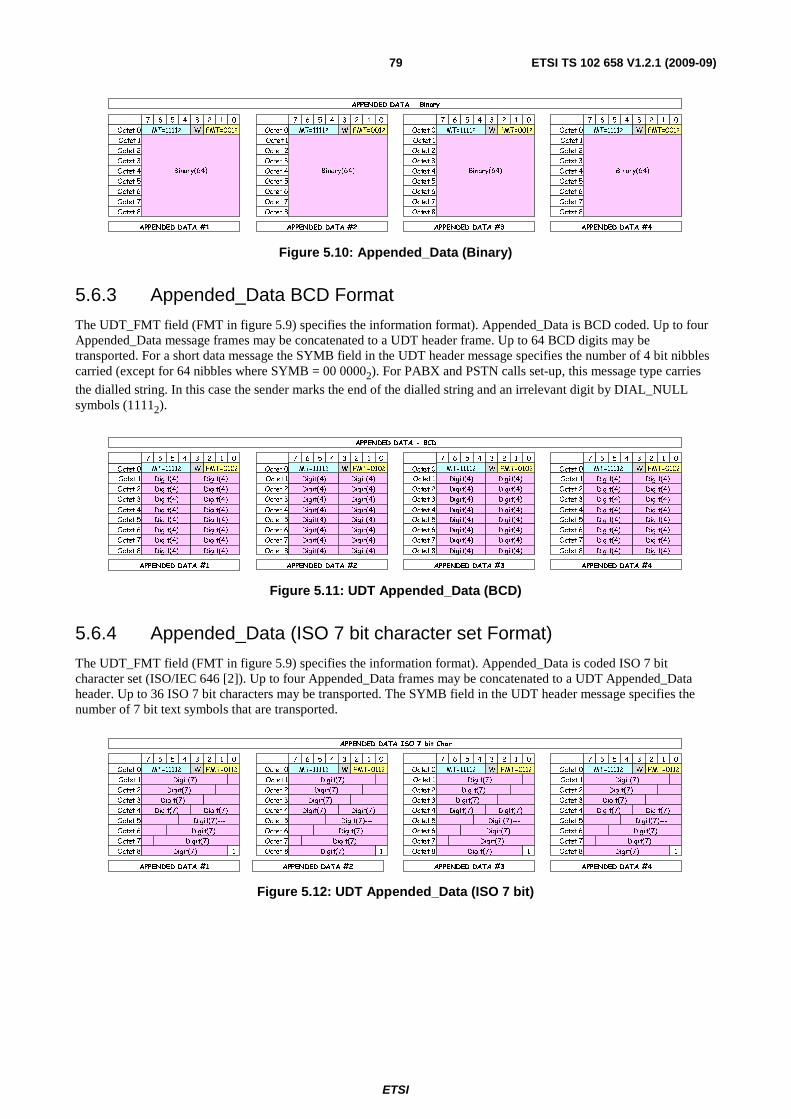
ETSI
ETSI TS 102 658 V1.2.1 (2009-09)79
Binary(64)
7 6 5 4 3 2 1 0
Octet 0
Octet 1
Octet 2
Octet 3
Octet 4
Octet 5
Octet 6
Octet 7
Octet 8
APPENDED DATA - Binary
MT=11112
APPENDED DATA #1
Binary(64)
7 6 5 4 3 2 1 0
Octet 0
Octet 1
Octet 2
Octet 3
Octet 4
Octet 5
Octet 6
Octet 7
Octet 8
MT=11112
APPENDED DATA #2
Binary(64)
7 6 5 4 3 2 1 0
Octet 0
Octet 1
Octet 2
Octet 3
Octet 4
Octet 5
Octet 6
Octet 7
Octet 8
MT=11112
APPENDED DATA #3
Binary(64)
7 6 5 4 3 2 1 0
Octet 0
Octet 1
Octet 2
Octet 3
Octet 4
Octet 5
Octet 6
Octet 7
Octet 8
MT=11112
APPENDED DATA #4
FMT=0012W FMT=0012W FMT=0012WFMT=0012W
Figure 5.10: Appended_Data (Binary)
5.6.3 Appended_Data BCD Format
The UDT_FMT field (FMT in figure 5.9) specifies the information format). Appended_Data is BCD coded. Up to four Appended_Data message frames may be concatenated to a UDT header frame. Up to 64 BCD digits may be transported. For a short data message the SYMB field in the UDT header message specifies the number of 4 bit nibbles carried (except for 64 nibbles where SYMB = 00 00002). For PABX and PSTN calls set-up, this message type carries
the dialled string. In this case the sender marks the end of the dialled string and an irrelevant digit by DIAL_NULL symbols (11112).
7 6 5 4 3 2 1 0
Octet 0
Octet 1
Octet 2
Octet 3
Octet 4
Octet 5
Octet 6
Octet 7
Octet 8
Digit(4)
Digit(4)
Digit(4)
Digit(4) Digit(4)
Digit(4) Digit(4)
Digit(4) Digit(4)
Digit(4) Digit(4)
Digit(4) Digit(4)
Digit(4) Digit(4)
Digit(4)
APPENDED DATA #2
MT=11112
7 6 5 4 3 2 1 0
Octet 0
Octet 1
Octet 2
Octet 3
Octet 4
Octet 5
Octet 6
Octet 7
Octet 8
APPENDED DATA - BCD
Digit(4)
Digit(4)
Digit(4)
Digit(4) Digit(4)
Digit(4) Digit(4)
Digit(4) Digit(4)
Digit(4) Digit(4)
Digit(4) Digit(4)
Digit(4) Digit(4)
Digit(4)
APPENDED DATA #1
MT=11112
7 6 5 4 3 2 1 0
Octet 0
Octet 1
Octet 2
Octet 3
Octet 4
Octet 5
Octet 6
Octet 7
Octet 8
Digit(4)
Digit(4)
Digit(4)
Digit(4) Digit(4)
Digit(4) Digit(4)
Digit(4) Digit(4)
Digit(4) Digit(4)
Digit(4) Digit(4)
Digit(4) Digit(4)
Digit(4)
APPENDED DATA #3
MT=11112
7 6 5 4 3 2 1 0
Octet 0
Octet 1
Octet 2
Octet 3
Octet 4
Octet 5
Octet 6
Octet 7
Octet 8
Digit(4)
Digit(4)
Digit(4)
Digit(4) Digit(4)
Digit(4) Digit(4)
Digit(4) Digit(4)
Digit(4) Digit(4)
Digit(4) Digit(4)
Digit(4) Digit(4)
Digit(4)
APPENDED DATA #4
MT=11112FMT=0102W FMT=0102W FMT=0102WFMT=0102W
Figure 5.11: UDT Appended_Data (BCD)
5.6.4 Appended_Data (ISO 7 bit character set Format)
The UDT_FMT field (FMT in figure 5.9) specifies the information format). Appended_Data is coded ISO 7 bit character set (ISO/IEC 646 [2]). Up to four Appended_Data frames may be concatenated to a UDT Appended_Data header. Up to 36 ISO 7 bit characters may be transported. The SYMB field in the UDT header message specifies the number of 7 bit text symbols that are transported.
APPENDED DATA #4APPENDED DATA #3APPENDED DATA #2APPENDED DATA #1
APPENDED DATA ISO 7 bit Char
7 6 5 4 3 2 1
Octet 0
Octet 1
Octet 2
Octet 3
Octet 4
Octet 5
Octet 6
Octet 7
Octet 8
0
Digit(7)
Digit(7)
Digit(7)
Digit(7)
Digit(7)
MT=11112
Digit(7)
Digit(7)
Digit(7)---
1
FMT=0112W
Digit(7)
7 6 5 4 3 2 1
Octet 0
Octet 1
Octet 2
Octet 3
Octet 4
Octet 5
Octet 6
Octet 7
Octet 8
0
Digit(7)
Digit(7)
Digit(7)
Digit(7)
Digit(7)
MT=11112
Digit(7)
Digit(7)
Digit(7)---
1
FMT=0112W
Digit(7)
7 6 5 4 3 2 1
Octet 0
Octet 1
Octet 2
Octet 3
Octet 4
Octet 5
Octet 6
Octet 7
Octet 8
0
Digit(7)
Digit(7)
Digit(7)
Digit(7)
Digit(7)
MT=11112
Digit(7)
Digit(7)
Digit(7)---
1
FMT=0112W
Digit(7)
7 6 5 4 3 2 1
Octet 0
Octet 1
Octet 2
Octet 3
Octet 4
Octet 5
Octet 6
Octet 7
Octet 8
0
Digit(7)
Digit(7)
Digit(7)
Digit(7)
Digit(7)
MT=11112
Digit(7)
Digit(7)
Digit(7)---
1
FMT=0112W
Digit(7)
Figure 5.12: UDT Appended_Data (ISO 7 bit)
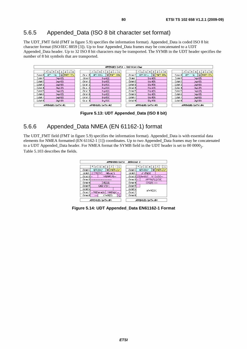
ETSI
ETSI TS 102 658 V1.2.1 (2009-09)80
5.6.5 Appended_Data (ISO 8 bit character set format)
The UDT_FMT field (FMT in figure 5.9) specifies the information format). Appended_Data is coded ISO 8 bit character format (ISO/IEC 8859 [3]). Up to four Appended_Data frames may be concatenated to a UDT Appended_Data header. Up to 32 ISO 8 bit characters may be transported. The SYMB in the UDT header specifies the number of 8 bit symbols that are transported.
APPENDED DATA - ISO 8 bit Char
APPENDED DATA #1 APPENDED DATA #2 APPENDED DATA #3 APPENDED DATA #4
7 6 5 4 3 2 1 0
Octet 0
Octet 1
Octet 2
Octet 3
Octet 4
Octet 5
Octet 6
Octet 7
Octet 8
Digit(8)
Digit(8)
Digit(8)
Digit(8)
Digit(8)
Digit(8)
Digit(8)
Digit(8)
MT=11112 FMT=1002W
7 6 5 4 3 2 1 0
Octet 0
Octet 1
Octet 2
Octet 3
Octet 4
Octet 5
Octet 6
Octet 7
Octet 8
Digit(8)
Digit(8)
Digit(8)
Digit(8)
Digit(8)
Digit(8)
Digit(8)
Digit(8)
MT=11112 FMT=1002W
7 6 5 4 3 2 1 0
Octet 0
Octet 1
Octet 2
Octet 3
Octet 4
Octet 5
Octet 6
Octet 7
Octet 8
Digit(8)
Digit(8)
Digit(8)
Digit(8)
Digit(8)
Digit(8)
Digit(8)
Digit(8)
MT=11112 FMT=1002W
7 6 5 4 3 2 1 0
Octet 0
Octet 1
Octet 2
Octet 3
Octet 4
Octet 5
Octet 6
Octet 7
Octet 8
Digit(8)
Digit(8)
Digit(8)
Digit(8)
Digit(8)
Digit(8)
Digit(8)
Digit(8)
MT=11112 FMT=1002W
Figure 5.13: UDT Appended_Data (ISO 8 bit)
5.6.6 Appended_Data NMEA (EN 61162-1) format
The UDT_FMT field (FMT in figure 5.9) specifies the information format). Appended_Data is with essential data elements for NMEA formatted (EN 61162-1 [1]) coordinates. Up to two Appended_Data frames may be concatenated to a UDT Appended_Data header. For NMEA format the SYMB field in the UDT header is set to 00 00002.
Table 5.103 describes the fields.
SPARE(31)
7 6 5 4 3 2 1 0
Octet 0
Octet 1
Octet 2
Octet 3
Octet 4
Octet 5
Octet 6
Octet 7
Octet 8
APPENDED DATA - IEC61162-2
C NS EW
Q
NDEG(7)---
NMIN(6)---
--------------------------
EMINF(14)----
--EMINmm(6)
--
EDEG(8)
SPEED(7) [SOG]
NMINF(14)---
----------------------
APPENDED DATA #1
FMT=1012WMT=11112
APPENDED DATA #2
7 6 5 4 3 2 1 0
Octet 0
Octet 1
Octet 2
Octet 3
Octet 4
Octet 5
Octet 6
Octet 7
Octet 8
UTChh(5)
UTCmm(6)
---
UTCss(6)---
--
MT=11112FMT=1012W
---- SPARE(5)
COG(9) ----
--
Figure 5.14: UDT Appended_Data EN61162-1 Format
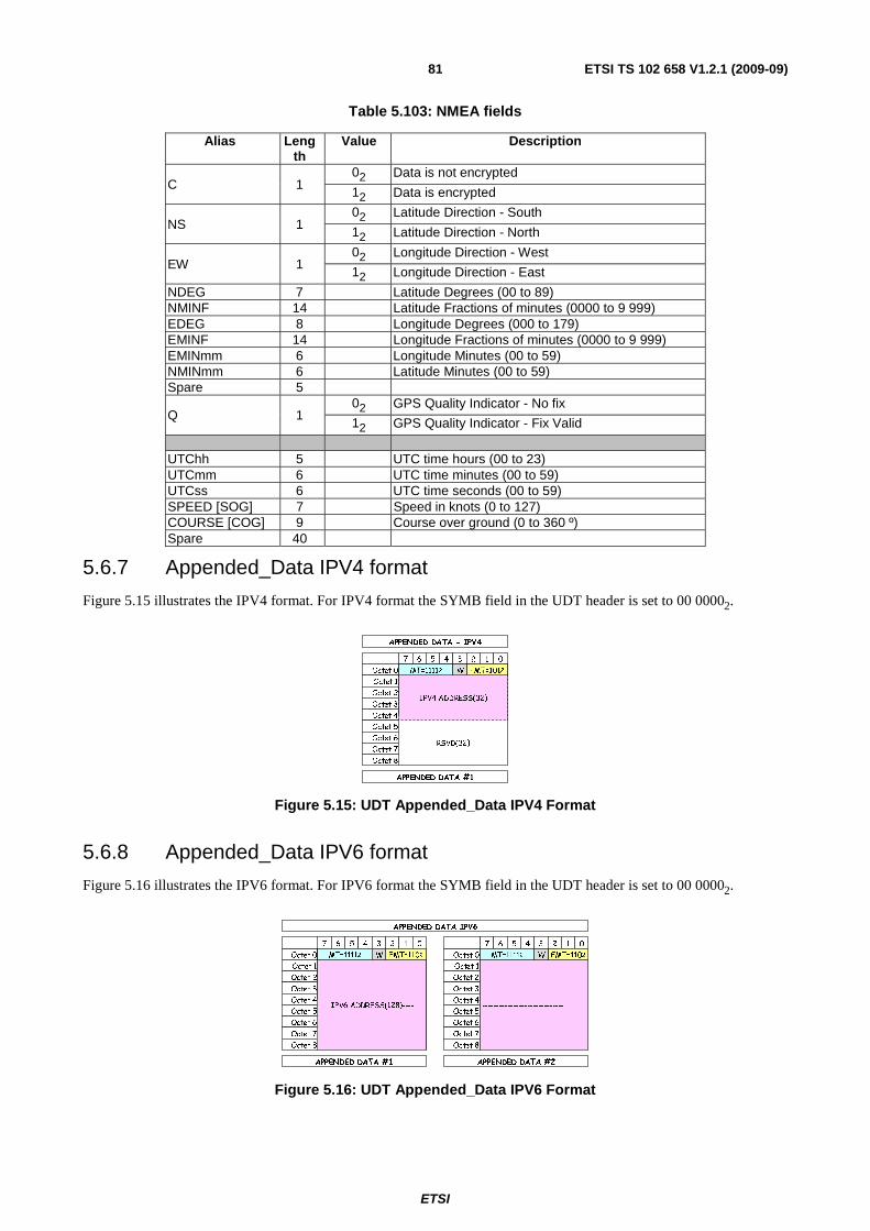
ETSI
ETSI TS 102 658 V1.2.1 (2009-09)81
Table 5.103: NMEA fields
Alias Length
Value Description
C 1 02 Data is not encrypted
12 Data is encrypted
NS 1 02 Latitude Direction - South
12 Latitude Direction - North
EW 1 02 Longitude Direction - West
12 Longitude Direction - East
NDEG 7 Latitude Degrees (00 to 89) NMINF 14 Latitude Fractions of minutes (0000 to 9 999) EDEG 8 Longitude Degrees (000 to 179) EMINF 14 Longitude Fractions of minutes (0000 to 9 999) EMINmm 6 Longitude Minutes (00 to 59) NMINmm 6 Latitude Minutes (00 to 59) Spare 5
Q 1 02 GPS Quality Indicator - No fix
12 GPS Quality Indicator - Fix Valid
UTChh 5 UTC time hours (00 to 23) UTCmm 6 UTC time minutes (00 to 59) UTCss 6 UTC time seconds (00 to 59) SPEED [SOG] 7 Speed in knots (0 to 127) COURSE [COG] 9 Course over ground (0 to 360 º) Spare 40
5.6.7 Appended_Data IPV4 format
Figure 5.15 illustrates the IPV4 format. For IPV4 format the SYMB field in the UDT header is set to 00 00002.
RSVD(32)
7 6 5 4 3 2 1 0
Octet 0
Octet 1
Octet 2
Octet 3
Octet 4
Octet 5
Octet 6
Octet 7
Octet 8
APPENDED DATA - IPV4
IPV4 ADDRESS(32)
APPENDED DATA #1
MT=11112 FMT=1012W
Figure 5.15: UDT Appended_Data IPV4 Format
5.6.8 Appended_Data IPV6 format
Figure 5.16 illustrates the IPV6 format. For IPV6 format the SYMB field in the UDT header is set to 00 00002.
IPV6 ADDRESS(128)----
7 6 5 4 3 2 1 0
Octet 0
Octet 1
Octet 2
Octet 3
Octet 4
Octet 5
Octet 6
Octet 7
Octet 8
APPENDED DATA IPV6
APPENDED DATA #1 APPENDED DATA #2
7 6 5 4 3 2 1 0
Octet 0
Octet 1
Octet 2
Octet 3
Octet 4
Octet 5
Octet 6
Octet 7
Octet 8
-----------------------------
MT=11112 FMT=1102W MT=11112 FMT=1102W
Figure 5.16: UDT Appended_Data IPV6 Format
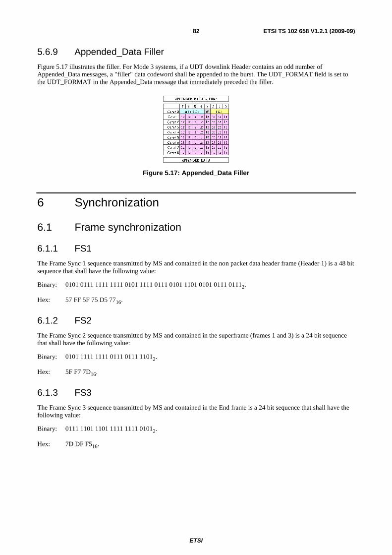
ETSI
ETSI TS 102 658 V1.2.1 (2009-09)82
5.6.9 Appended_Data Filler
Figure 5.17 illustrates the filler. For Mode 3 systems, if a UDT downlink Header contains an odd number of Appended_Data messages, a "filler" data codeword shall be appended to the burst. The UDT_FORMAT field is set to the UDT_FORMAT in the Appended_Data message that immediately preceded the filler.
7 6 5 4 3 2 1 0
Oc tet 0
O ctet 1
Oc tet 2
Oc tet 3
Oc tet 4
Oc tet 5
Oc tet 6
Oc tet 7
Oc tet 8
APPENDED DATA - F i l ler
M T =11112
APPEN DED DATA
F MTW
1212 12 12 1212 12 12
1212 12 12 1212 12 12
1212 12 12 1212 12 12
1212 12 12 1212 12 12
1212 12 12 1212 12 12
1212 12 12 1212 12 12
1212 12 12 1212 12 12
1212 12 12 1212 12 12
Figure 5.17: Appended_Data Filler
6 Synchronization
6.1 Frame synchronization
6.1.1 FS1
The Frame Sync 1 sequence transmitted by MS and contained in the non packet data header frame (Header 1) is a 48 bit sequence that shall have the following value:
Binary: 0101 0111 1111 1111 0101 1111 0111 0101 1101 0101 0111 01112.
Hex: 57 FF 5F 75 D5 7716.
6.1.2 FS2
The Frame Sync 2 sequence transmitted by MS and contained in the superframe (frames 1 and 3) is a 24 bit sequence that shall have the following value:
Binary: 0101 1111 1111 0111 0111 11012.
Hex: 5F F7 7D16.
6.1.3 FS3
The Frame Sync 3 sequence transmitted by MS and contained in the End frame is a 24 bit sequence that shall have the following value:
Binary: 0111 1101 1101 1111 1111 01012.
Hex: 7D DF F516.
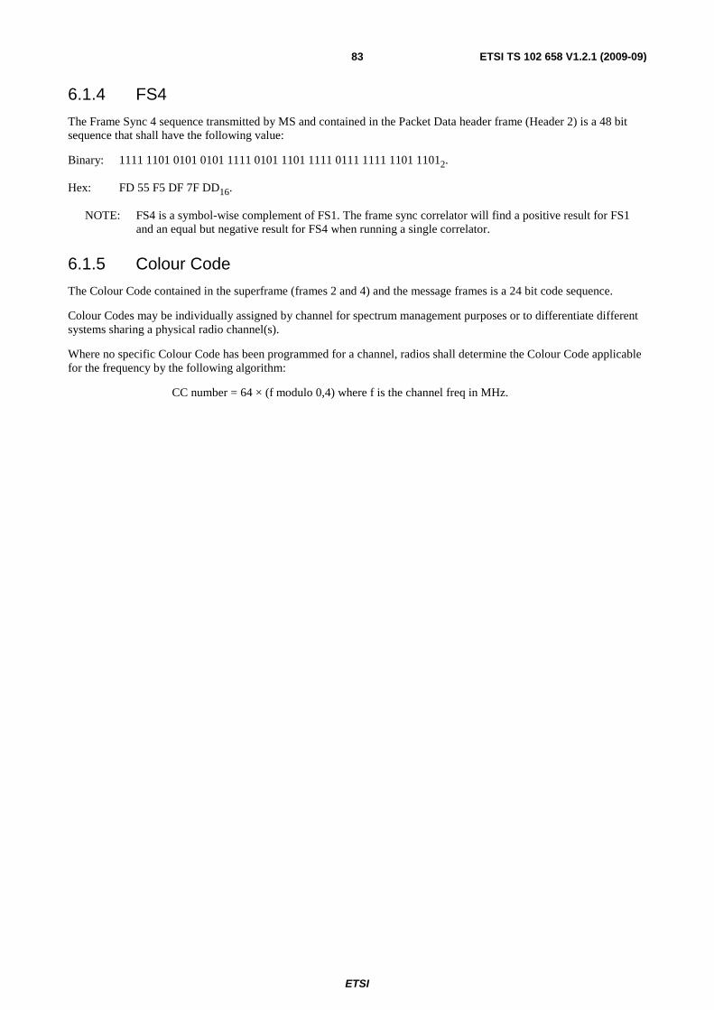
ETSI
ETSI TS 102 658 V1.2.1 (2009-09)83
6.1.4 FS4
The Frame Sync 4 sequence transmitted by MS and contained in the Packet Data header frame (Header 2) is a 48 bit sequence that shall have the following value:
Binary: 1111 1101 0101 0101 1111 0101 1101 1111 0111 1111 1101 11012.
Hex: FD 55 F5 DF 7F DD16.
NOTE: FS4 is a symbol-wise complement of FS1. The frame sync correlator will find a positive result for FS1 and an equal but negative result for FS4 when running a single correlator.
6.1.5 Colour Code
The Colour Code contained in the superframe (frames 2 and 4) and the message frames is a 24 bit code sequence.
Colour Codes may be individually assigned by channel for spectrum management purposes or to differentiate different systems sharing a physical radio channel(s).
Where no specific Colour Code has been programmed for a channel, radios shall determine the Colour Code applicable for the frequency by the following algorithm:
CC number = 64 × (f modulo 0,4) where f is the channel freq in MHz.
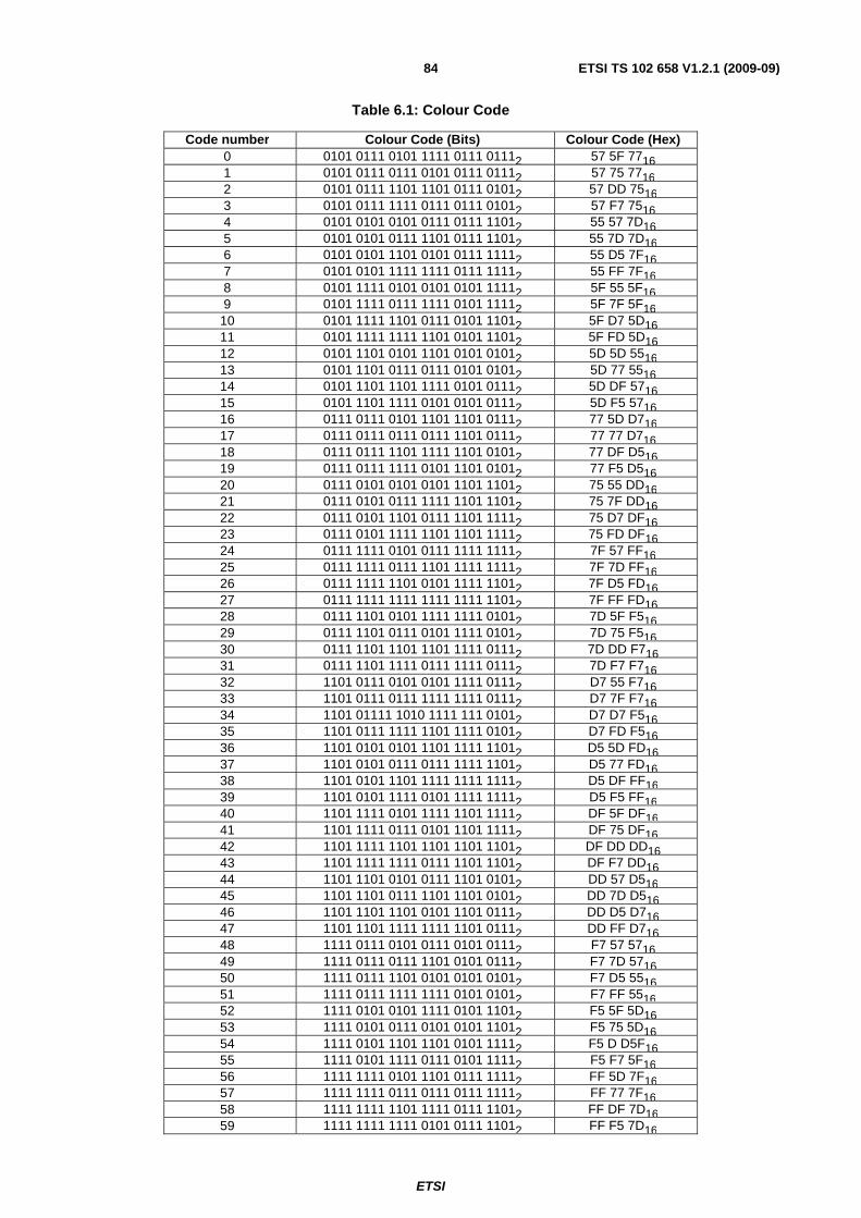
ETSI
ETSI TS 102 658 V1.2.1 (2009-09)84
Table 6.1: Colour Code
Code number Colour Code (Bits) Colour Code (Hex) 0 0101 0111 0101 1111 0111 01112 57 5F 7716 1 0101 0111 0111 0101 0111 01112 57 75 7716 2 0101 0111 1101 1101 0111 01012 57 DD 7516 3 0101 0111 1111 0111 0111 01012 57 F7 7516 4 0101 0101 0101 0111 0111 11012 55 57 7D16 5 0101 0101 0111 1101 0111 11012 55 7D 7D16 6 0101 0101 1101 0101 0111 11112 55 D5 7F16 7 0101 0101 1111 1111 0111 11112 55 FF 7F16 8 0101 1111 0101 0101 0101 11112 5F 55 5F16 9 0101 1111 0111 1111 0101 11112 5F 7F 5F16
10 0101 1111 1101 0111 0101 11012 5F D7 5D16 11 0101 1111 1111 1101 0101 11012 5F FD 5D16 12 0101 1101 0101 1101 0101 01012 5D 5D 5516 13 0101 1101 0111 0111 0101 01012 5D 77 5516 14 0101 1101 1101 1111 0101 01112 5D DF 5716 15 0101 1101 1111 0101 0101 01112 5D F5 5716 16 0111 0111 0101 1101 1101 01112 77 5D D716 17 0111 0111 0111 0111 1101 01112 77 77 D716 18 0111 0111 1101 1111 1101 01012 77 DF D516 19 0111 0111 1111 0101 1101 01012 77 F5 D516 20 0111 0101 0101 0101 1101 11012 75 55 DD16 21 0111 0101 0111 1111 1101 11012 75 7F DD16 22 0111 0101 1101 0111 1101 11112 75 D7 DF16 23 0111 0101 1111 1101 1101 11112 75 FD DF16 24 0111 1111 0101 0111 1111 11112 7F 57 FF16 25 0111 1111 0111 1101 1111 11112 7F 7D FF16 26 0111 1111 1101 0101 1111 11012 7F D5 FD16 27 0111 1111 1111 1111 1111 11012 7F FF FD16 28 0111 1101 0101 1111 1111 01012 7D 5F F516 29 0111 1101 0111 0101 1111 01012 7D 75 F516 30 0111 1101 1101 1101 1111 01112 7D DD F716 31 0111 1101 1111 0111 1111 01112 7D F7 F716 32 1101 0111 0101 0101 1111 01112 D7 55 F716 33 1101 0111 0111 1111 1111 01112 D7 7F F716 34 1101 01111 1010 1111 111 01012 D7 D7 F516 35 1101 0111 1111 1101 1111 01012 D7 FD F516 36 1101 0101 0101 1101 1111 11012 D5 5D FD16 37 1101 0101 0111 0111 1111 11012 D5 77 FD16 38 1101 0101 1101 1111 1111 11112 D5 DF FF16 39 1101 0101 1111 0101 1111 11112 D5 F5 FF16 40 1101 1111 0101 1111 1101 11112 DF 5F DF16 41 1101 1111 0111 0101 1101 11112 DF 75 DF16 42 1101 1111 1101 1101 1101 11012 DF DD DD16 43 1101 1111 1111 0111 1101 11012 DF F7 DD16 44 1101 1101 0101 0111 1101 01012 DD 57 D516 45 1101 1101 0111 1101 1101 01012 DD 7D D516 46 1101 1101 1101 0101 1101 01112 DD D5 D716 47 1101 1101 1111 1111 1101 01112 DD FF D716 48 1111 0111 0101 0111 0101 01112 F7 57 5716 49 1111 0111 0111 1101 0101 01112 F7 7D 5716 50 1111 0111 1101 0101 0101 01012 F7 D5 5516 51 1111 0111 1111 1111 0101 01012 F7 FF 5516 52 1111 0101 0101 1111 0101 11012 F5 5F 5D16 53 1111 0101 0111 0101 0101 11012 F5 75 5D16 54 1111 0101 1101 1101 0101 11112 F5 D D5F16 55 1111 0101 1111 0111 0101 11112 F5 F7 5F16 56 1111 1111 0101 1101 0111 11112 FF 5D 7F16 57 1111 1111 0111 0111 0111 11112 FF 77 7F16 58 1111 1111 1101 1111 0111 11012 FF DF 7D16 59 1111 1111 1111 0101 0111 11012 FF F5 7D16

ETSI
ETSI TS 102 658 V1.2.1 (2009-09)85
Code number Colour Code (Bits) Colour Code (Hex) 60 1111 1101 0101 0101 0111 01012 FD 55 7516 61 1111 1101 0111 1111 0111 01012 FD 7F 7516 62 1111 1101 1101 0111 0111 01112 FD D7 7716 63 1111 1101 1111 1101 0111 01112 FD FD 7716
6.1.6 Preamble
The preamble consists of a minimum of 72 bits and shall have the form 5F 5F 5F 5F 5F 5F 5F 5F 5F16. If a preamble
pattern longer than 72 bits is used then the repeated 5F16 pattern (0101 11112) shall be maintained.
7 Interleaving and FEC coding
7.1 CRC addition
Table 7.1: CRC coding
Use CRC Polynomial Frame (CCH) CRC7 X7 + X3 + 1 Message (MI
and Header (HI)
CRC8 X8 + X2 + X1 + 1
7.2 Hamming code A shortened Hamming code (12,8) is employed and the generator matrix is illustrated in table 7.2.
X7, X6, X5, X4, X3, X2, X1, 1 are Identity bits (8 bit): C3,C2,C1,C0 are Parity bits (4 bit).
Table 7.2: Generator matrix
12 11 10 9 8 7 6 5 4 3 2 1 X7 X6 X5 X4 X3 X2 X1 1 C3 C2 C1 C0
1 1 0 0 0 0 0 0 0 1 1 1 0 2 0 1 0 0 0 0 0 0 0 1 1 1 3 0 0 1 0 0 0 0 0 1 0 1 0 4 0 0 0 1 0 0 0 0 0 1 0 1 5 0 0 0 0 1 0 0 0 1 0 1 1 6 0 0 0 0 0 1 0 0 1 1 0 0 7 0 0 0 0 0 0 1 0 0 1 1 0 8 0 0 0 0 0 0 0 1 0 0 1 1
Shortened Hamming code (12,8) Polynomial: X4 + X + 1.

ETSI
ETSI TS 102 658 V1.2.1 (2009-09)86
7.3 Scrambling The scrambling polynomial is X9 + X5 + 1 with an initial preset value of all "1"s.
S9 S8 S7 S6 S5 S4 S3 S2 S1
+ SCRAMBLED
DATA OUT
X9 + X5 + 1 Initial Value = all '12'
+
DATA IN
Figure 7.1: Scrambling format
7.4 Interleaving There are two interleaving matrices, one for the TCH and one for the MI/HI field.
TCH interleave structure matrix:
Table 7.3: TCH Interleaving matrix
1 2 3 4 5 6 1 1 13 25 37 49 61 2 2 14 26 38 50 62 3 3 15 27 39 51 63 4 4 16 28 40 52 64 5 5 17 29 41 53 65 6 6 18 30 42 54 66 7 7 19 31 43 55 67 8 8 20 32 44 56 68 9 9 21 33 45 57 69 10 10 22 34 46 58 70 11 11 23 35 47 59 71 12 12 24 36 48 60 72
The Interleave Structure Matrix Map (Tx side: 12 bit × 10).
Table 7.4: MI and HI field Interleaving matrix
1 2 3 4 5 6 7 8 9 10 1 1 13 25 37 49 61 73 85 97 109 2 2 14 26 38 50 62 74 86 98 110 3 3 15 27 39 51 63 75 87 99 111 4 4 16 28 40 52 64 76 88 100 112 5 5 17 29 41 53 65 77 89 101 113 6 6 18 30 42 54 66 78 90 102 114 7 7 19 31 43 55 67 79 91 103 115 8 8 20 32 44 56 68 80 92 104 116 9 9 21 33 45 57 69 81 93 105 117 10 10 22 34 46 58 70 82 94 106 118 11 11 23 35 47 59 71 83 95 107 119 12 12 24 36 48 60 72 84 96 108 120
NOTE: Applied in the Header MI0/MI1 and HI0/HI1.

ETSI
ETSI TS 102 658 V1.2.1 (2009-09)87
Use of interleaving matrices:
• Transmit data is input to the matrix in vertical columns from top left to lower right. Data is output from the matrix in horizontal rows from top left to lower right.
• Receive data is input to the matrix in horizontal rows from top left to lower right. Data is output from the matrix in vertical columns from top left to lower right.
7.5 FEC coding of CCH (superframe) There are a total of 41 bits of CCH data.
The 7 bit CRC checksum is added using the polynomial given in clause 7.1 giving a total of 48 bits.
These 48 bits are now separated into 6 bytes. Each byte is now coded by a shortened 12,8 Hamming Code (see clause 7.2) giving 6 × 12 bit blocks.
To protect against burst interference, these 6 × 12 bit blocks are now interleaved using the 12 × 6 TCH interleaving matrix given in table 7.4.
Then the interleaved CCH data is scrambled using the polynomial given in clause 7.3.
7.6 FEC coding of MI (message info') and HI (header info') There are a total of 72 bits of MI/HI data.
The 8 bit CRC checksum is added using the polynomial given in clause 7.1 giving a total of 80 bits.
These 80 bits are now separated into 10 bytes. Each byte is now coded by a shortened 12,8 Hamming Code (see clause 7.2) giving 10 × 12 bit blocks.
To protect against burst interference, these 10 × 12 bit blocks are now interleaved using the 12 × 10 HI interleaving matrix given in clause 7.4.
Then the interleaved MI/HI data is scrambled using the polynomial given in clause 7.3.
7.7 FEC coding of END information There are a total of 17 bits of END information.
The 7 bit CRC checksum is added using the polynomial given in clause 7.1 giving a total of 24 bits.
These 24 bits are now separated into 3 bytes. Each byte is now coded by a shortened 12,8 Hamming Code (see clause 7.2) giving 3 × 12 bit blocks. These 36 bits are now repeated and the total 72 bits are scrambled using the polynomial described in clause 7.3.
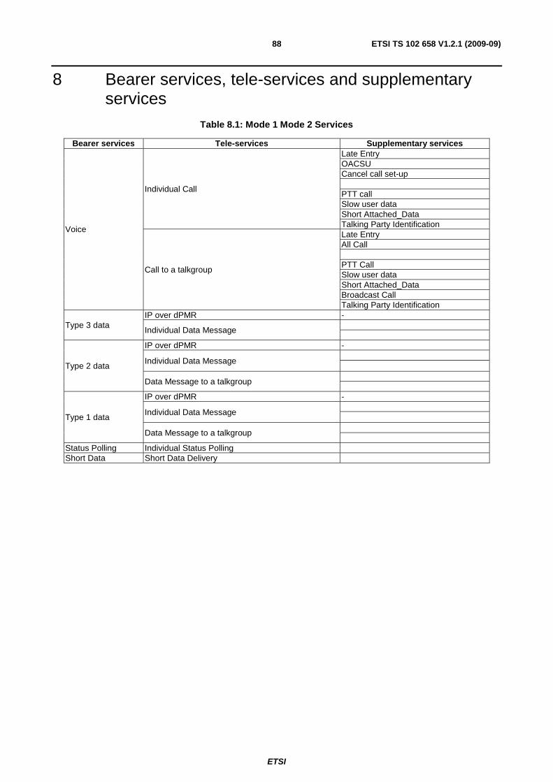
ETSI
ETSI TS 102 658 V1.2.1 (2009-09)88
8 Bearer services, tele-services and supplementary services
Table 8.1: Mode 1 Mode 2 Services
Bearer services Tele-services Supplementary services
Voice
Individual Call
Late Entry OACSU Cancel call set-up PTT call Slow user data Short Attached_Data Talking Party Identification
Call to a talkgroup
Late Entry All Call PTT Call Slow user data Short Attached_Data Broadcast Call Talking Party Identification
Type 3 data IP over dPMR -
Individual Data Message
Type 2 data
IP over dPMR -
Individual Data Message
Data Message to a talkgroup
Type 1 data
IP over dPMR -
Individual Data Message
Data Message to a talkgroup
Status Polling Individual Status Polling Short Data Short Data Delivery
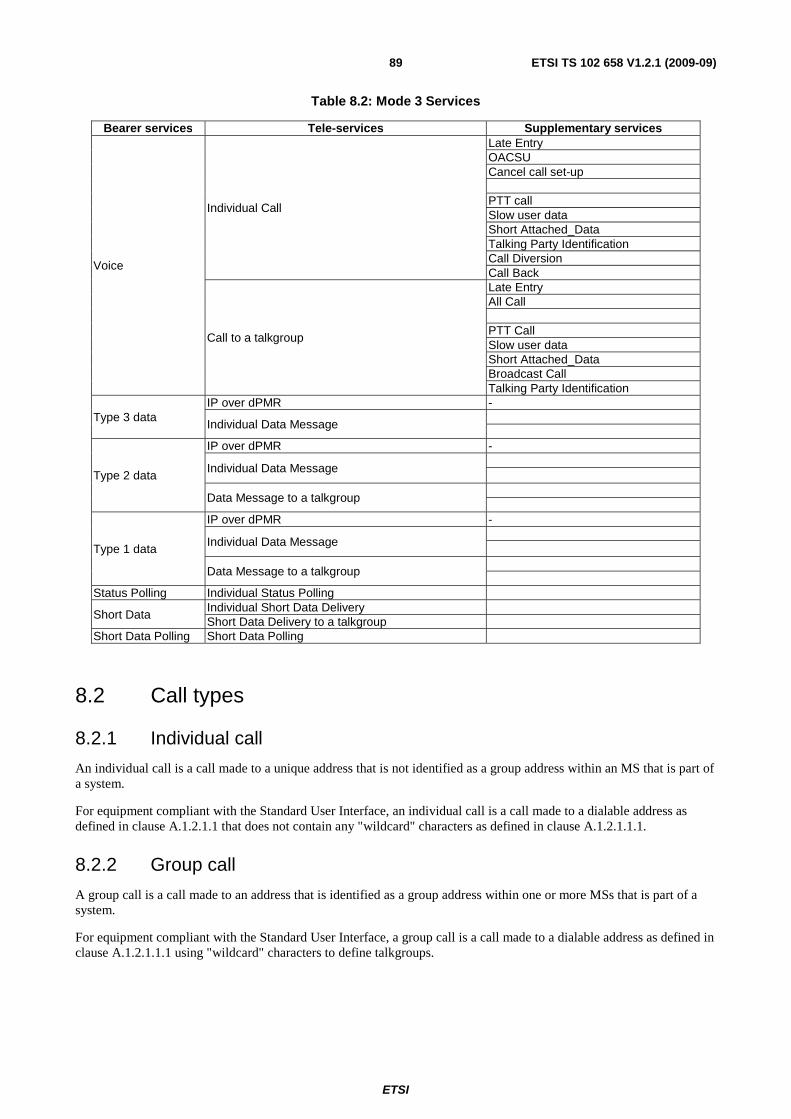
ETSI
ETSI TS 102 658 V1.2.1 (2009-09)89
Table 8.2: Mode 3 Services
Bearer services Tele-services Supplementary services
Voice
Individual Call
Late Entry OACSU Cancel call set-up PTT call Slow user data Short Attached_Data Talking Party Identification Call Diversion Call Back
Call to a talkgroup
Late Entry All Call PTT Call Slow user data Short Attached_Data Broadcast Call Talking Party Identification
Type 3 data IP over dPMR -
Individual Data Message
Type 2 data
IP over dPMR -
Individual Data Message
Data Message to a talkgroup
Type 1 data
IP over dPMR -
Individual Data Message
Data Message to a talkgroup
Status Polling Individual Status Polling
Short Data Individual Short Data Delivery Short Data Delivery to a talkgroup
Short Data Polling Short Data Polling
8.2 Call types
8.2.1 Individual call
An individual call is a call made to a unique address that is not identified as a group address within an MS that is part of a system.
For equipment compliant with the Standard User Interface, an individual call is a call made to a dialable address as defined in clause A.1.2.1.1 that does not contain any "wildcard" characters as defined in clause A.1.2.1.1.1.
8.2.2 Group call
A group call is a call made to an address that is identified as a group address within one or more MSs that is part of a system.
For equipment compliant with the Standard User Interface, a group call is a call made to a dialable address as defined in clause A.1.2.1.1.1 using "wildcard" characters to define talkgroups.

ETSI
ETSI TS 102 658 V1.2.1 (2009-09)90
8.3 Addressing MS, BS and Gateway addresses that do not require extended addressing is based on an allocation of 24 bits.
For equipment compliant with the Standard User Interface radios shall use a 7 digit addressing scheme that is encoded into the 24 bit address field as detailed in annex A.
8.4 Colour Codes Colour Codes can be individually assigned by channel for spectrum management purposes or to differentiate independent co-channel networks.
Where no specific Colour Code has been programmed for a channel, MS shall determine the Colour Code applicable for the frequency by the algorithm defined in clause 6.1.5.
8.5 Messages
8.5.1 Downlink Traffic Channel messages
Ind icates a data m essage
m ay be appended
Ind icates a superf ram e
is be appended
Acknow ledgem ents
N ACK (negative)
ACK (positive)
Headers
S upefram e Vo ice header
T raffic Ch anne l
Dow nlink messages
M essage
T erm ination
EN D
Payload
Voice Pay load
D ata Pay load
D ata H eader
Packet D ata H eader
Connection R equest
D isconnection Request
M a intenance
Id le
Preservation
Protection
Figure 8.1: Downlink Traffic Channel Messages
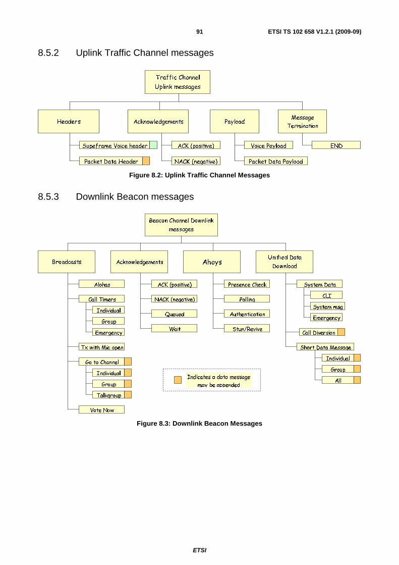
ETSI
ETSI TS 102 658 V1.2.1 (2009-09)91
8.5.2 Uplink Traffic Channel messages
Acknowledgements
NACK (negative)
ACK (positive)
Headers
Supeframe Voice header
Traffic Channel
Uplink messages
Message
Termination
END
Payload
Voice Payload
Packet Data PayloadPacket Data Header
Figure 8.2: Uplink Traffic Channel Messages
8.5.3 Downlink Beacon messages
AhoysAcknowledgementsUnified Data
Download
Beacon Channel Downlink
messages
Broadcasts
Alohas
Call Timers
Individual
Group
Emergency
Tx with Mic open
Go to Channel
Individual
Group
Talkgroup
NACK (negative)
ACK (positive)
Queued
Wait
Polling
Presence Check
Authentication
Vote Now
Short Data Message
System Data
Stun/Revive
CLI
System msg
Emergency
Individual
Group
AllIndicates a data message
may be appended
Call Diversion
Figure 8.3: Downlink Beacon Messages

ETSI
ETSI TS 102 658 V1.2.1 (2009-09)92
8.5.4 Uplink Beacon messages
Acknowledgements
Beacon Channel
Uplink messages
NACK
ACK
ESN Response
Complementary Data
Uplink Extended Address
Short Data Message
Individual
Talkgroup
All Call
Uplink Data
Unified Data UploadRandom Access
Talkgroup Serv
Individual Serv
Secondary Serv
Indicates a data message
may be appended
Uplink Dial Digits
Call Support
Uplink IP adress Digits
Figure 8.4: Uplink Beacon Messages
9 Packet data
9.1 Format Packet data uses a different format to the normal communications frame format. The use of frame sync 4 (FS4) indicates that the frames following are in the PDF format.
The basic PDF format is illustrated in figure 9.1.
H 2 H eader F rame T y p e 2 E nd F r amePack et D ata F rameD E
ED 0 D 1 D 2 D NH 2
Figure 9.1: PDF format
Total length of a data frame D(N) = 80 × (pdS + 1) ms.
The value of pdS transmitted indicates the number of 80 ms frames.
Figure 9.2 illustrates concatenated PDF frames.
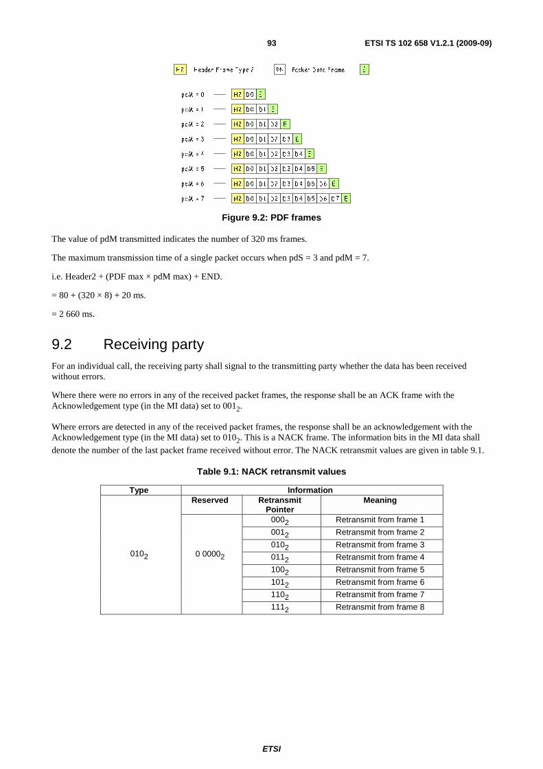
ETSI
ETSI TS 102 658 V1.2.1 (2009-09)93
H 2 H eader F rame T y p e 2 Pack et D ata F rameDN E
ED 0 D 1 D 2H2 D 3 D 4 D 5
ED 0 D 1 D 2H2 D 3 D 4
ED 0 D 1 D 2H2 D 3
ED 0 D 1 D 2H2
ED 0 D 1H2
ED 0H2
ED 0 D 1 D 2H2 D 3 D 4 D 5 D 6
ED 0 D 1 D 2 D 7H2 D 3 D 4 D 5 D 6
p dM = 0
p dM = 1
p dM = 2
p dM = 3
p dM = 4
p dM = 5
p dM = 6
p dM = 7
Figure 9.2: PDF frames
The value of pdM transmitted indicates the number of 320 ms frames.
The maximum transmission time of a single packet occurs when pdS = 3 and pdM = 7.
i.e. Header2 + (PDF max × pdM max) + END.
= 80 + (320 × 8) + 20 ms.
= 2 660 ms.
9.2 Receiving party For an individual call, the receiving party shall signal to the transmitting party whether the data has been received without errors.
Where there were no errors in any of the received packet frames, the response shall be an ACK frame with the Acknowledgement type (in the MI data) set to 0012.
Where errors are detected in any of the received packet frames, the response shall be an acknowledgement with the Acknowledgement type (in the MI data) set to 0102. This is a NACK frame. The information bits in the MI data shall
denote the number of the last packet frame received without error. The NACK retransmit values are given in table 9.1.
Table 9.1: NACK retransmit values
Type Information
0102
Reserved Retransmit Pointer
Meaning
0 00002
0002 Retransmit from frame 1
0012 Retransmit from frame 2
0102 Retransmit from frame 3
0112 Retransmit from frame 4
1002 Retransmit from frame 5
1012 Retransmit from frame 6
1102 Retransmit from frame 7
1112 Retransmit from frame 8

ETSI
ETSI TS 102 658 V1.2.1 (2009-09)94
9.3 Packet frame coding Packet Data Frame format.
Table 9.2: Packet Data Frame Format
CC PAR DATA 24 bits 72 = bits 288 bits (pdS = 0), 672 (pdS = 1), 1 056 (pdS = 2), 1 440 (pdS = 3)
Table 9.3: Packet data frame coding
Tx frame Info bits FEC Transfer bits CC Colour Code ALL 24 Clause 6.1.5 24
PAR Parameter (41) CRC 7 bit (12,8)
Short Hamming Interleave
12 × 6 Scramble
72
288 672
1 056 1 440
N Packet frame number ALL 3 LEN Data length (BYTE) *1 ALL 8
DUMMY DUMMY BITS ALL 14 CRC-D CRC for DATA field ALL 16 DATA User data pdS = 0
pdS = 1 pdS = 2 pdS = 3
ALL ALL ALL ALL
288 672
1 056 1 440
NONE
NOTE 1: DUMMY bits in the data frame are all set to zero. NOTE 2: N: Number of each individual packet frame transmitted in this item counting from 0 up to the value given by
pdM in the Packet data Header. Data length 3 bit.
Definition.
Table 9.4: Number of Packet Frames
field value length meaning N 0 to 7 (dec) 3 Frame Number
9.4 Data frame size The data frame size is declared in the Header frame MI field pdS (see table 5.5.19.3).
The length of a packet data transmission shall always be an integral number of 80 ms units (i.e. same as the normal FDMA frames).
Table 9.5: Data Frame Size
pdS = 0 total length = 80 ms / 384 bits.
CC PAR Data 288 bits (36 bytes)
pdS = 1 total length = 160 ms / 768 bits.
CC PAR Data 672 bits (84 bytes)
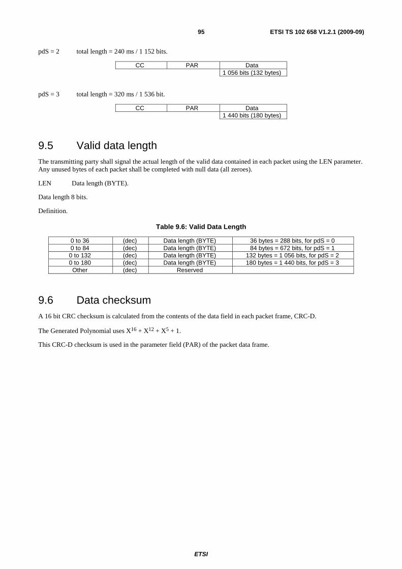
ETSI
ETSI TS 102 658 V1.2.1 (2009-09)95
pdS = 2 total length = 240 ms / 1 152 bits.
CC PAR Data 1 056 bits (132 bytes)
pdS = 3 total length = 320 ms / 1 536 bit.
CC PAR Data 1 440 bits (180 bytes)
9.5 Valid data length The transmitting party shall signal the actual length of the valid data contained in each packet using the LEN parameter. Any unused bytes of each packet shall be completed with null data (all zeroes).
LEN Data length (BYTE).
Data length 8 bits.
Definition.
Table 9.6: Valid Data Length
0 to 36 (dec) Data length (BYTE) 36 bytes = 288 bits, for pdS = 0 0 to 84 (dec) Data length (BYTE) 84 bytes = 672 bits, for pdS = 1
0 to 132 (dec) Data length (BYTE) 132 bytes = 1 056 bits, for pdS = 2 0 to 180 (dec) Data length (BYTE) 180 bytes = 1 440 bits, for pdS = 3
Other (dec) Reserved
9.6 Data checksum A 16 bit CRC checksum is calculated from the contents of the data field in each packet frame, CRC-D.
The Generated Polynomial uses X16 + X12 + X5 + 1.
This CRC-D checksum is used in the parameter field (PAR) of the packet data frame.
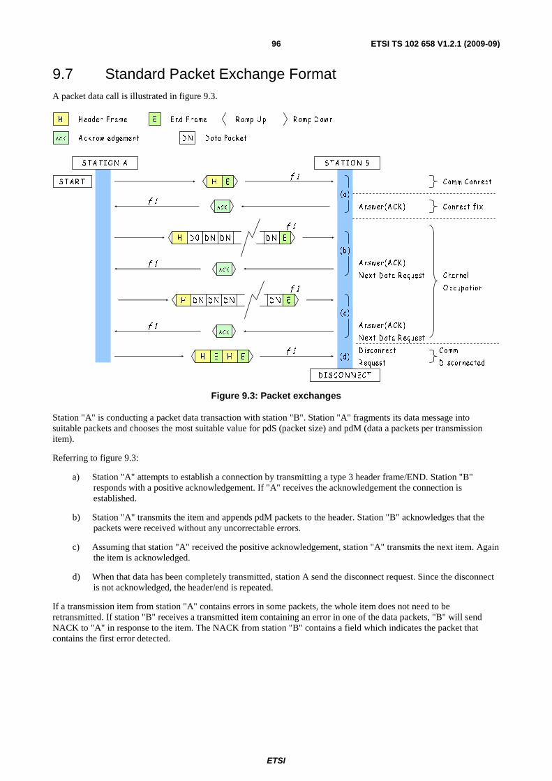
ETSI
ETSI TS 102 658 V1.2.1 (2009-09)96
9.7 Standard Packet Exchange Format A packet data call is illustrated in figure 9.3.
H
AC K
Header F rame
A ck now ledgement D ata Pack etD N
E E nd F rame R amp U p R amp D ow n
S TA R T H E
ACK
AC K
AC K
H E H E
ST A TI O N A S TA TI O N B
D I SC O N N E C T
f 1
f 1
f 1
f 1
f 1
f 1
A nswer(A C K )
C omm C onnect
A nswer(A C K )
N ext D ata R equest
A nswer(A C K )
N ext D ata R equest
C onnect fix
C hannel
O ccup ation
D isconnect
R equest
C omm
D isconnected
EH D ND 0 D N D N
f 1
EH D ND N D N D N
(a)
(d)
(b )
(c)
Figure 9.3: Packet exchanges
Station "A" is conducting a packet data transaction with station "B". Station "A" fragments its data message into suitable packets and chooses the most suitable value for pdS (packet size) and pdM (data a packets per transmission item).
Referring to figure 9.3:
a) Station "A" attempts to establish a connection by transmitting a type 3 header frame/END. Station "B" responds with a positive acknowledgement. If "A" receives the acknowledgement the connection is established.
b) Station "A" transmits the item and appends pdM packets to the header. Station "B" acknowledges that the packets were received without any uncorrectable errors.
c) Assuming that station "A" received the positive acknowledgement, station "A" transmits the next item. Again the item is acknowledged.
d) When that data has been completely transmitted, station A send the disconnect request. Since the disconnect is not acknowledged, the header/end is repeated.
If a transmission item from station "A" contains errors in some packets, the whole item does not need to be retransmitted. If station "B" receives a transmitted item containing an error in one of the data packets, "B" will send NACK to "A" in response to the item. The NACK from station "B" contains a field which indicates the packet that contains the first error detected.

ETSI
ETSI TS 102 658 V1.2.1 (2009-09)97
Figure 9.4 illustrates a packet data call with an error.
H
ACK
H eader F rame
A ck now ledgement D ata Pack etD N
E E nd F rame R amp U p R amp D ow n
S T A R T H E
ACK
AC K
S T A T I O N A S T A T I O N B
f 1
f 1
f 1
f 1
f 1
f 1
A nsw er(A C K )
C omm C onnect
A nsw er(A C K )
N ext D ata R equest
A nsw er(N A C K )
N ext D ata R equest
C onnect fix
C hannel
O ccup ation
H ED 1D 0 D 2 D 3 D 4 D 5 D 6 D 7
NAC K
H ED 1 D 8D 2 D 3 D 4 D 5 D 6 D 7
(b )
(c )
(a )
(d)
f 1
H ED 9 D16D10 D11 D12 D13 D14 D15 (f )
(e)
Figure 9.4: Packet retransmissions
Referring to figure 9.4:
a) Station "A" attempts to establish a connection by transmitting a type 3 header frame/END. Station "B" responds with a positive acknowledgement. Station "A" receives the acknowledgement and the connection was established.
b) Station "A" transmits the item and appends 8 (pdM=01112) packets to the header;.
c) Station "B" received the header and D0 correctly but D1 was received with errors. Station "B" therefore transmitted a NACK (Type=0102, Information = 0 asking for a retransmission from data packet #1.
d) Station "A" transmits the item from data packet #1.
e) When that data has been completely transmitted, station "A" send the disconnect request. Since the disconnect is not acknowledged, the header/end is repeated.
If Station "A" has sent a packet and does not receive any acknowledgement, station "A" may send a Repeat_Last_Ack + END message instead of repeating the packet data item. If station B receives a Repeat_Last_Ack + END message, it shall send verbatim the acknowledgement that was previously sent.
10 Call Procedures The facilities described for dPMR are related to user initiated call procedures, e.g. talkgroup speech call, individual speech call, data call etc. The services defined for dPMR contains intrinsic (embedded) signalling or procedures which may support user initiated call procedures. Some services are visible to users others are not and will be processed by the MS or BS itself.
The individual call service provides voice call or data call service between two parties. Only the parties engaged in the call can hear each other. The individual call is initiated at the user level by selecting the desired individual called party ID via a predefined selection procedure and then activating a mechanism to initiate the call.
ETSI
ETSI TS 102 658 V1.2.1 (2009-09)98
The group call service provides voice call or data call service between one individual user and a predetermined group of MS. All parties in the talkgroup can hear each other. The talkgroup call is initiated at the user level by selecting the desired talkgroup ID via a predefined selection procedure and then activating a mechanism to initiate the call.
For a voice call, dPMR MSs shall employ a traffic channel transmit TimeOut timer (TV_Item) which limits the time of a single transmission item. This timer shall be set to the value TV_Item whenever the PTT key is pressed and counts down to zero. For a data call, dPMR MSs shall have a traffic channel transmit TimeOut timer (TD_Item) which limits the maximum time of a single data transmission item.
If the transmit TimeOut timer expires during a voice transmission, then the MS shall stop transmitting after the end of the current superframe plus the END frame, and may not re-transmit until PTT has been released and pressed again. If the transmit TimeOut timer expires during a data transmission, then the MS shall stop transmitting immediately (see note).
NOTE: MS are configured with the parameter TD_Item timer and are therefore able determine a data frame length that ensures the TimeOut timer will not expire.
A Mode 1 system can support a range of services including MS to MS individual calls for voice, status, and data, and calls to talkgroups.
A Mode 2 or Mode 3 system can allocate resources for additional services including calls to and from line connected destinations, and complementary services.
Complementary data may be sent between MS and the network during the call set-up phase using the Complementary Data Transfer Service to poll for, or deliver additional information using a Unified Data Transport method. Examples include:
• the uplink of dialling digits for calls to the PSTN, PABX extensions;
• the transport of MS location information using data collected from EN 61162-1 [1] compatible devices;
• the transport of any complementary user or system data;
• the downlink of CLI information for calls from PSTN and PABX gateways to the called MS(s).
10.1 Call procedures for Mode 1 This clause defines the following facilities for Mode 1 equipment. MS may support:
a) MS to MS Individual Voice Call Service;
b) MS to talkgroup Voice Call Service;
c) MS to MS Individual T1, T2 and T3 Data Call Service;
d) MS from MS Individual status polling;
e) MS to MS Individual Short Data Delivery Service;
f) MS to talkgroup Short Data Delivery Service.
In addition a power save feature is specified.
10.1.1 Common procedures for Voice and Data calls
10.1.1.1 Call set up.
Individual Mode 1 calls may be preceded by a called party check illustrated in figure 10.1.

ETSI
ETSI TS 102 658 V1.2.1 (2009-09)99
H
ACK
Header Frame
Acknowledgement
E End Frame Ramp Up Ramp Down
START H E
ACK
STATION A STATION B
f 1
f 1
Station B
Check
(a)
(b)
Figure 10.1: Mode 1 Called Party Check
The called party check consists of a Connection_Request Header + End_Message pair described in tables 10.1 and 10.2.
Table 10.1: Connection_Request Header for a Mode_1 Called Party Check
Alias Alias Alias Value Length Meaning MT 00012 4 Message Type = Connection_Request Header
PARMS
ID0 + 1 24 Called Station individual MS ID ID2 + 3 24 Calling Station ID
M 3 Communications Mode V 2 Version (002 for standard TCH)
F 012 2 Comms Format = peer to peer
EP 1 Priority (02 for normal priority 12 for emergency)
PM N/A 1 Not Applicable for this particular message
MI MI_TYPE N/A 3 Called Party Check = 0002
MI_DET N/A 8 Not Applicable for this particular message
The M field indicates the service that will form the content of the payload (voice/data, etc).
The V field indicates if the payload is dPMR standard traffic channel content.
The EP field = 02 for a normal priority call or 12 for an emergency call.
Table 10.2: END message fields for a Mode 1 called party check
Alias Length Value Meaning ET 2 002 End type = Normal End Frame
ARQ 2 012 ACK requested
Tx_WAIT 4 value Tx_Wait STAT 5 N/A Not Applicable for this particular message RSVD 4 00002 Reserved
Called parties receiving a Connection_Request shall respond with a T_ACK frame. If the called party wishes to accept the call and is able to support the call service being checked, the T_ACK frame shall set the MI_TYPE = 0012 as
illustrated in table 10.3.
Table 10.3: MI Parameters in a T_ACK for a called party check
Alias Length Value Meaning
MI_TYPE 3
0012 ACK Connection_Request accepted. Call may proceed
0112 NACK Connection_Request Denied or the called party does not support the call service requested
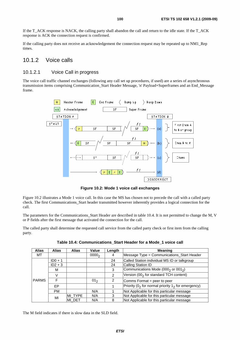
ETSI
ETSI TS 102 658 V1.2.1 (2009-09)100
If the T_ACK response is NACK, the calling party shall abandon the call and return to the idle state. If the T_ACK response is ACK the connection request is confirmed.
If the calling party does not receive an acknowledgement the connection request may be repeated up to NM1_Rep times.
10.1.2 Voice calls
10.1.2.1 Voice Call in progress
The voice call traffic channel exchanges (following any call set up procedures, if used) are a series of asynchronous transmission items comprising Communication_Start Header Message, 'n' Payload+Superframes and an End_Message frame.
S T A R T
H E H E
S T A T IO N A S T A T I O N B
D IS C O N N E C T
S F S F S F
S F HE S F S F
f 1
f 1
F irst Item A
to B or gr oup
Item B to A
Items
f 1
S FH S F S F E
(c)
(a)
(b )
(d)
f 1
H
AC K
H eader F rame
A ck now ledgement S up er F r ameS F
E E nd F r ame R amp U p R amp D ow n
Figure 10.2: Mode 1 voice call exchanges
Figure 10.2 illustrates a Mode 1 voice call. In this case the MS has chosen not to precede the call with a called party check. The first Communications_Start header transmitted however inherently provides a logical connection for the call.
The parameters for the Communications_Start Header are described in table 10.4. It is not permitted to change the M, V or P fields after the first message that activated the connection for the call.
The called party shall determine the requested call service from the called party check or first item from the calling party.
Table 10.4: Communications_Start Header for a Mode_1 voice call
Alias Alias Alias Value Length Meaning MT 00002 4 Message Type = Communications_Start Header
PARMS
ID0 + 1 24 Called Station individual MS ID or talkgroup ID2 + 3 24 Calling Station ID
M 3 Communications Mode (0002 or 0012)
V 2 Version (002 for standard TCH content)
F 012 2 Comms Format = peer to peer
EP 1 Priority (02 for normal priority 12 for emergency)
PM N/A 1 Not Applicable for this particular message
MI MI_TYPE N/A 3 Not Applicable for this particular message MI_DET N/A 8 Not Applicable for this particular message
The M field indicates if there is slow data in the SLD field.
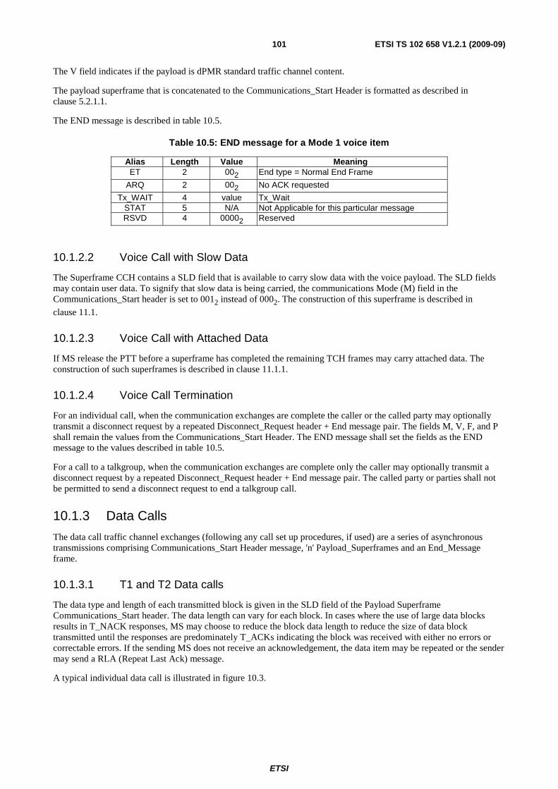
ETSI
ETSI TS 102 658 V1.2.1 (2009-09)101
The V field indicates if the payload is dPMR standard traffic channel content.
The payload superframe that is concatenated to the Communications_Start Header is formatted as described in clause 5.2.1.1.
The END message is described in table 10.5.
Table 10.5: END message for a Mode 1 voice item
Alias Length Value Meaning ET 2 002 End type = Normal End Frame
ARQ 2 002 No ACK requested
Tx_WAIT 4 value Tx_Wait STAT 5 N/A Not Applicable for this particular message RSVD 4 00002 Reserved
10.1.2.2 Voice Call with Slow Data
The Superframe CCH contains a SLD field that is available to carry slow data with the voice payload. The SLD fields may contain user data. To signify that slow data is being carried, the communications Mode (M) field in the Communications_Start header is set to 0012 instead of 0002. The construction of this superframe is described in
clause 11.1.
10.1.2.3 Voice Call with Attached Data
If MS release the PTT before a superframe has completed the remaining TCH frames may carry attached data. The construction of such superframes is described in clause 11.1.1.
10.1.2.4 Voice Call Termination
For an individual call, when the communication exchanges are complete the caller or the called party may optionally transmit a disconnect request by a repeated Disconnect_Request header + End message pair. The fields M, V, F, and P shall remain the values from the Communications_Start Header. The END message shall set the fields as the END message to the values described in table 10.5.
For a call to a talkgroup, when the communication exchanges are complete only the caller may optionally transmit a disconnect request by a repeated Disconnect_Request header + End message pair. The called party or parties shall not be permitted to send a disconnect request to end a talkgroup call.
10.1.3 Data Calls
The data call traffic channel exchanges (following any call set up procedures, if used) are a series of asynchronous transmissions comprising Communications_Start Header message, 'n' Payload_Superframes and an End_Message frame.
10.1.3.1 T1 and T2 Data calls
The data type and length of each transmitted block is given in the SLD field of the Payload Superframe Communications_Start header. The data length can vary for each block. In cases where the use of large data blocks results in T_NACK responses, MS may choose to reduce the block data length to reduce the size of data block transmitted until the responses are predominately T_ACKs indicating the block was received with either no errors or correctable errors. If the sending MS does not receive an acknowledgement, the data item may be repeated or the sender may send a RLA (Repeat Last Ack) message.
A typical individual data call is illustrated in figure 10.3.
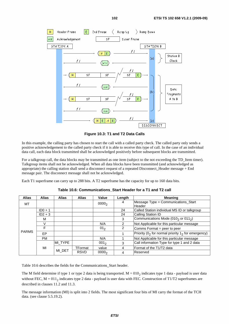
ETSI
ETSI TS 102 658 V1.2.1 (2009-09)102
H E
ACK
ACK
AC K
H E H E
S T A TIO N A S TA T IO N B
D IS CO N N EC T
S FH S F S F E
S FH S F S F E
f 1
f 1
f 1
f 1
f 1
f 1
f 1
S tation B
Check
D ata
F ragments
A to B
(c)
(a)
(b )
H
ACK
Header F rame
A cknow ledgement S up er F rameS F
E End F rame R amp U p R amp D ow n
Figure 10.3: T1 and T2 Data Calls
In this example, the calling party has chosen to start the call with a called party check. The called party only sends a positive acknowledgement to the called party check if it is able to receive this type of call. In the case of an individual data call, each data block transmitted shall be acknowledged positively before subsequent blocks are transmitted.
For a talkgroup call, the data blocks may be transmitted as one item (subject to the not exceeding the TD_Item timer). Talkgroup items shall not be acknowledged. When all data blocks have been transmitted (and acknowledged as appropriate) the calling station shall send a disconnect request of a repeated Disconnect_Header message + End message pair. The disconnect message shall not be acknowledged.
Each T1 superframe can carry up to 288 bits. A T2 superframe has the capacity for up to 160 data bits.
Table 10.6: Communications_Start Header for a T1 and T2 call
Alias Alias Alias Alias Value Length Meaning
MT 00002 4 Message Type = Communications_Start Header
PARMS
ID0 + 1 24 Called Station individual MS ID or talkgroup ID2 + 3 24 Calling Station ID
M 3 Communications Mode (0102 or 0112)
V N/A 2 Not Applicable for this particular message F 012 2 Comms Format = peer to peer
EP 1 Priority (02 for normal priority 12 for emergency)
PM N/A 1 Not Applicable for this particular message
MI
MI_TYPE 0012 3 Call information Type for type 1 and 2 data
MI_DET TFormat value 4 Format of the T1/T2 data RSVD 00002 4 Reserved
Table 10.6 describes the fields for the Communications_Start header.
The M field determine if type 1 or type 2 data is being transported. M = 0102 indicates type 1 data - payload is user data
without FEC, M = 0112 indicates type 2 data - payload is user data with FEC. Construction of T1/T2 superframes are
described in clauses 11.2 and 11.3.
The message information (MI) is split into 2 fields. The most significant four bits of MI carry the format of the TCH data. (see clause 5.5.19.2).

ETSI
ETSI TS 102 658 V1.2.1 (2009-09)103
10.1.3.2 T3 (Packet) Data Calls
Packet data uses a different format to the normal communications frame format. The use of frame sync 4 (FS4) indicates to a recipient of a message that the frames following are in a packet data format.
The basic packet data format is illustrated in figure 10.4.
EH2 D1 D2 D3 D4 DN
H2 Header Frame Type 2 End FramePacket Data Frame E
Ramp Up Ramp Down
DN
Figure 10.4: Packet Data Format
The Message Information field in a Header Frame type 2 (H2) contains a parameter pdS that indicates the number of bits carried in each packet data frame (DN in figure 10.4).
The value of pdS transmitted indicates the number of 80 ms frames in a data packet frame.
Total length of a packet data frame D(N) = 80 × (pdS + 1) ms.
Figure 10.5 illustrates concatenated Packet Data Frames:
pdM = 0
pdM = 1
pdM = 2
pdM = 3
pdM = 4
pdM = 5
pdM = 6
pdM = 7
H2 ED1 D2
H2 ED1
H2 ED1 D2 D3
H2 ED1 D2 D3 D4
H2 ED1 D2 D3 D4 D5
H2 ED1 D2 D3 D4 D5 D6
H2 ED1 D2 D3 D4 D5 D6 D7
H2 ED1 D2 D3 D4 D5 D6 D7 D8
H2 Header Frame Type 2 Packet Data Frame E End FrameDN
Figure 10.5: Packet Data frames
The value - pdM indicates the number of packet data frames.
The maximum transmission time of a single packet occurs when pdS = 3 and pdM = 7.
i.e. Header2 + (80 × [pdS+1]) max × pdM max) + END.
= 80 + (320 × 8) + 20 ms.
= 2 660 ms.
T3 (Packet) data calls are by definition always individual calls as each packet is acknowledged. MS may choose to initiate a called party check before the first packet item is transmitted.
A packet data call is illustrated in figure 10.6.

ETSI
ETSI TS 102 658 V1.2.1 (2009-09)104
H
ACK
Header Frame
Acknowledgement Data PacketDN
E End Frame Ramp Up Ramp Down
START H E
ACK
ACK
ACK
H E H E
STATION A STATION B
END
f 1
f 1
f 1
f 1
f 1
f 1
Answer(ACK)
Call Party
Answer(ACK)
Next Data Request
Answer(ACK)
Next Data Request Channel
Occupation
End of
Transaction
EH2 DND1 DN DN
f 1
EH2 DNDN DN DN
(a)
(d)
(b)
(c)
Check
Figure 10.6: T3 (Packet) Data Call
Station "A" is conducting a packet data transaction with station "B". Station "A" fragments its data message into suitable packets and chooses the most suitable value for pdS (packet size) and pdM (data a packets per transmission item).
Referring to figure 10.6:
a) Station "A" chooses to send a called party check before sending the first packet by transmitting a Called Party Check frame MT = 00012 header frame/END. Station "B" responds with a positive acknowledgement.
b) Station "A" transmits the item and appends pdM packets to the header. Station "B" acknowledges that the packets were received without any uncorrectable errors.
c) Assuming that station "A" received the positive acknowledgement, station "A" transmits the next item. Again the item is acknowledged.
d) When that data has been completely transmitted, station "A" send the disconnect request. Since the disconnect is not acknowledged, the header/end is repeated. That ends the transaction.
If a transmission item from station "A" contains errors in some packets, the whole item does not need to be retransmitted. If station "B" receives a transmitted item containing an error in one of the data packets, "B" shall send a NACK to "A" in response to the item. The NACK from station "B" contains the Message_Information field that indicates the packet that contains the first error detected.
Construction of T3 superframes is described in clause 11.4.
Figure 10.7 illustrates a packet data call with an errors.
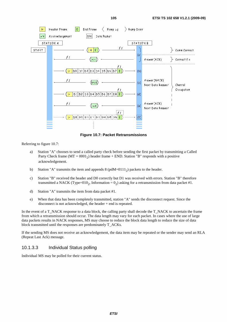
ETSI
ETSI TS 102 658 V1.2.1 (2009-09)105
H
ACK
H eader F rame
A ck now ledgement D ata Pack etD N
E E nd F rame R amp U p R amp D ow n
S T A R T H E
ACK
ACK
S T A T I O N A S T A T I O N B
f 1
f 1
f 1
f 1
f 1
f 1
A nsw er (A C K )
C omm C onnect
A nsw er (A C K )
N ext D ata R equest
A nsw er (N A C K )
N ext D ata R equest
C onnect f ix
C hannel
O ccup ation
H ED 1D 0 D 2 D 3 D 4 D 5 D 6 D 7
NACK
H ED 1 D 8D 2 D 3 D 4 D 5 D 6 D 7
(b )
(c)
(a )
(d)
f 1
H ED 9 D16D10 D11 D12 D13 D14 D15 (f )
(e)
Figure 10.7: Packet Retransmissions
Referring to figure 10.7:
a) Station "A" chooses to send a called party check before sending the first packet by transmitting a Called Party Check frame (MT = 00012) header frame + END. Station "B" responds with a positive
acknowledgement.
b) Station "A" transmits the item and appends 8 (pdM=01112) packets to the header.
c) Station "B" received the header and D0 correctly but D1 was received with errors. Station "B" therefore transmitted a NACK (Type=0102, Information = 02) asking for a retransmission from data packet #1.
d) Station "A" transmits the item from data packet #1.
e) When that data has been completely transmitted, station "A" sends the disconnect request. Since the disconnect is not acknowledged, the header + end is repeated.
In the event of a T_NACK response to a data block, the calling party shall decode the T_NACK to ascertain the frame from which a retransmission should occur. The data length may vary for each packet. In cases where the use of large data packets results in NACK responses, MS may choose to reduce the block data length to reduce the size of data block transmitted until the responses are predominately T_ACKs.
If the sending MS does not receive an acknowledgement, the data item may be repeated or the sender may send an RLA (Repeat Last Ack) message.
10.1.3.3 Individual Status polling
Individual MS may be polled for their current status.
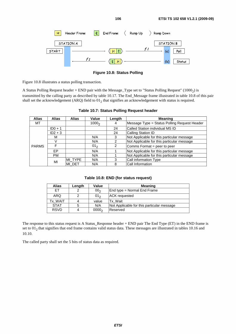
ETSI
ETSI TS 102 658 V1.2.1 (2009-09)106
H Header Frame E End Frame Ramp Up Ramp Down
START H E
STATION A STATION B
f 1
f 1
Poll(a)
(b)HE Status
Figure 10.8: Status Polling
Figure 10.8 illustrates a status polling transaction.
A Status Polling Request header + END pair with the Message_Type set to "Status Polling Request" (10002) is
transmitted by the calling party as described by table 10.17. The End_Message frame illustrated in table 10.8 of this pair shall set the acknowledgement (ARQ) field to 012 that signifies an acknowledgement with status is required.
Table 10.7: Status Polling Request header
Alias Alias Alias Value Length Meaning MT 10002 4 Message Type = Status Polling Request Header
PARMS
ID0 + 1 24 Called Station individual MS ID ID2 + 3 24 Calling Station ID
M N/A 3 Not Applicable for this particular message V N/A 2 Not Applicable for this particular message F 012 2 Comms Format = peer to peer
EP N/A 1 Not Applicable for this particular message PM N/A 1 Not Applicable for this particular message
MI MI_TYPE N/A 3 Call information Type MI_DET N/A 8 Call Information
Table 10.8: END (for status request)
Alias Length Value Meaning ET 2 002 End type = Normal End Frame
ARQ 2 012 ACK requested
Tx_WAIT 4 value Tx_Wait STAT 5 N/A Not Applicable for this particular message RSVD 4 00002 Reserved
The response to this status request is A Status_Response header + END pair The End Type (ET) in the END frame is set to 012 that signifies that end frame contains valid status data. These messages are illustrated in tables 10.16 and
10.10.
The called party shall set the 5 bits of status data as required.
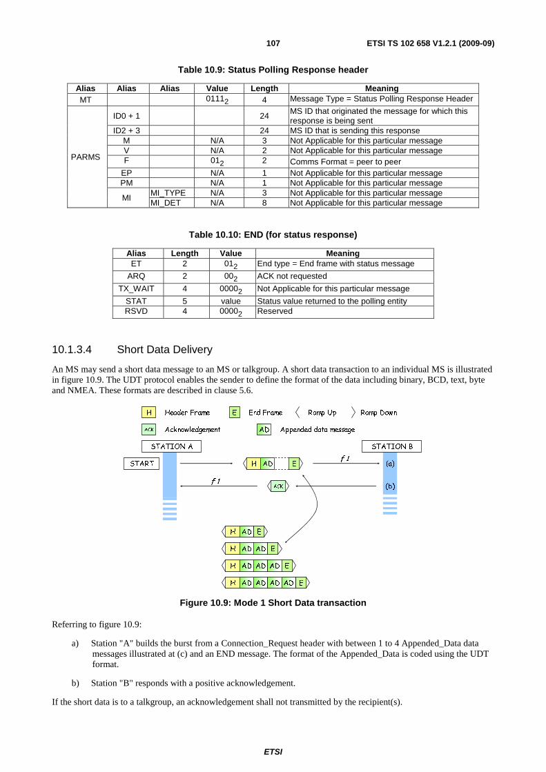
ETSI
ETSI TS 102 658 V1.2.1 (2009-09)107
Table 10.9: Status Polling Response header
Alias Alias Alias Value Length Meaning MT 01112 4 Message Type = Status Polling Response Header
PARMS
ID0 + 1
24 MS ID that originated the message for which this response is being sent
ID2 + 3 24 MS ID that is sending this response M N/A 3 Not Applicable for this particular message V N/A 2 Not Applicable for this particular message F 012 2 Comms Format = peer to peer
EP N/A 1 Not Applicable for this particular message PM N/A 1 Not Applicable for this particular message
MI MI_TYPE N/A 3 Not Applicable for this particular message MI_DET N/A 8 Not Applicable for this particular message
Table 10.10: END (for status response)
Alias Length Value Meaning ET 2 012 End type = End frame with status message
ARQ 2 002 ACK not requested
TX_WAIT 4 00002 Not Applicable for this particular message
STAT 5 value Status value returned to the polling entity RSVD 4 00002 Reserved
10.1.3.4 Short Data Delivery
An MS may send a short data message to an MS or talkgroup. A short data transaction to an individual MS is illustrated in figure 10.9. The UDT protocol enables the sender to define the format of the data including binary, BCD, text, byte and NMEA. These formats are described in clause 5.6.
START
ACK
STATION A STATION B
f 1
f 1
(a)
(b)
H EAD
H EAD
H AD AD E
EH AD AD AD AD
H AD AD AD E
H
ACK
Header Frame
Acknowledgement
E End Frame Ramp Up Ramp Down
AD Appended data message
Figure 10.9: Mode 1 Short Data transaction
Referring to figure 10.9:
a) Station "A" builds the burst from a Connection_Request header with between 1 to 4 Appended_Data data messages illustrated at (c) and an END message. The format of the Appended_Data is coded using the UDT format.
b) Station "B" responds with a positive acknowledgement.
If the short data is to a talkgroup, an acknowledgement shall not transmitted by the recipient(s).
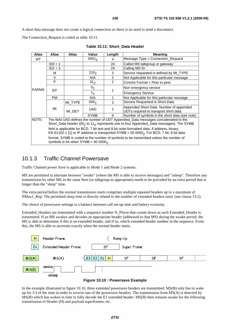
ETSI
ETSI TS 102 658 V1.2.1 (2009-09)108
A short data message does not create a logical connection so there is no need to send a disconnect.
The Connection_Request is coded as table 10.11.
Table 10.11: Short_Data Header
Alias Alias Alias Value Length Meaning MT 00012 4 Message Type = Connection_Request
PARMS
ID0 + 1 24 Called MS talkgroup or gateway ID2 + 3 24 Calling MS ID
M 1102 3 Service requested is defined by MI_TYPE V N/A 2 Not Applicable for this particular message F 012 2 Comms Format = Peer to peer
EP 02
1 Non emergency service
12 Emergency Service PM N/A 1 Not Applicable for this particular message
MI
MI_TYPE 0002 3 Service Requested is Short Data
MI_DET UAD 2 Appended Short Data. Number of appended
UDTs required to transport short data SYMB 6 Number of symbols in the short data (see note)
NOTE: The field UAD defines the number of UDT Appended_Data messages concatenated to the Short_Data header (002 to 112 represents one to four Appended_Data messages). The SYMB
field is applicable for BCD, 7 bit text and 8 bit octet formatted data. If address, binary, EN 61162-1 [1] or IP address is transported SYMB = 00 00002. For BCD, 7 bit, 8 bit data
format, SYMB is coded to the number of symbols to be transmitted unless the number of symbols is 64 when SYMB = 00 00002.
10.1.3 Traffic Channel Powersave
Traffic Channel power Save is applicable to Mode 1 and Mode 2 systems.
MS are permitted to alternate between "awake" (where the MS is able to receive messages) and "asleep". Therefore any transmission by other MS in the same fleet (or talkgroup as appropriate) needs to be preceded by an extra period that is longer than the "sleep" time.
The extra period before the normal transmission starts comprises multiple repeated headers up to a maximum of NMax1_Rep. The permitted sleep time is directly related to the number of extended headers used. (see clause 13.2).
The choice of powersave settings is a balance between call set-up time and battery economy.
Extended_Headers are transmitted with a sequence number N_PSave that counts down as each Extended_Header is transmitted. If an MS awakes and decodes an appropriate header (addressed to that MS) during the awake period, the MS is able to determine if this is an extended header, and if so, which extended header number in the sequence. From this, the MS is able to ascertain exactly when the normal header starts.
H Header Frame Ramp Up
En Super FrameSFExtended Header Frame
E3 E2 E1 H SF SF SFMS(A)
MS(B)
MS(A)
asleep
awake
Figure 10.10 : Powersave Example
In the example illustrated in figure 10.10, three extended powersave headers are transmitted. MS(B) only has to wake up for 1/3 of the time in order to receive one of the powersave headers. The transmission from MS(A) is detected by MS(B) which has woken in time to fully decode the E1 extended header. MS(B) then remains awake for the following transmission of Header (H) and payload superframes, etc.
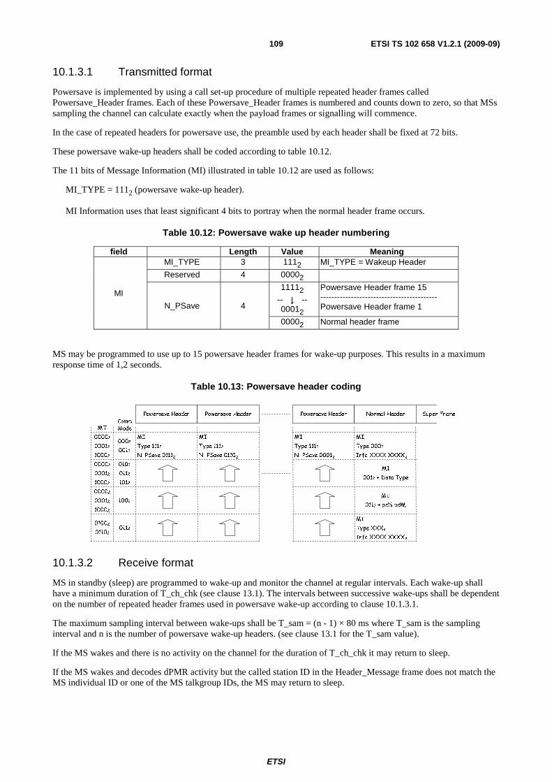
ETSI
ETSI TS 102 658 V1.2.1 (2009-09)109
10.1.3.1 Transmitted format
Powersave is implemented by using a call set-up procedure of multiple repeated header frames called Powersave_Header frames. Each of these Powersave_Header frames is numbered and counts down to zero, so that MSs sampling the channel can calculate exactly when the payload frames or signalling will commence.
In the case of repeated headers for powersave use, the preamble used by each header shall be fixed at 72 bits.
These powersave wake-up headers shall be coded according to table 10.12.
The 11 bits of Message Information (MI) illustrated in table 10.12 are used as follows:
MI_TYPE = 1112 (powersave wake-up header).
MI Information uses that least significant 4 bits to portray when the normal header frame occurs.
Table 10.12: Powersave wake up header numbering
field Length Value Meaning
MI
MI_TYPE 3 1112 MI_TYPE = Wakeup Header
Reserved 4 00002
N_PSave 4
11112
-- ↓ -- 00012
Powersave Header frame 15 ------------------------------------------ Powersave Header frame 1
00002 Normal header frame
MS may be programmed to use up to 15 powersave header frames for wake-up purposes. This results in a maximum response time of 1,2 seconds.
Table 10.13: Powersave header coding
CommModeMT
0002
0012
00002
00012
10002
MI
Type 1112
N_PSave 01102
MI
Type 1112
N_PSave 01112
0102
0112
1012
00002
00012
10002
00002
00012
10002
1002
01002
01102
Super FramePowersave Header Powersave Header Powersave Header Normal Header
MI
0012 + Data Type
0112
MI
Type 1112
N_PSave 00012
MI
Type 0002
Info XXXX XXXX2
MI
Type XXX2
Info XXXX XXXX2
MI
0112 + pdS pdM
10.1.3.2 Receive format
MS in standby (sleep) are programmed to wake-up and monitor the channel at regular intervals. Each wake-up shall have a minimum duration of T_ch_chk (see clause 13.1). The intervals between successive wake-ups shall be dependent on the number of repeated header frames used in powersave wake-up according to clause 10.1.3.1.
The maximum sampling interval between wake-ups shall be T_sam = (n - 1) × 80 ms where T_sam is the sampling interval and n is the number of powersave wake-up headers. (see clause 13.1 for the T_sam value).
If the MS wakes and there is no activity on the channel for the duration of T_ch_chk it may return to sleep.
If the MS wakes and decodes dPMR activity but the called station ID in the Header_Message frame does not match the MS individual ID or one of the MS talkgroup IDs, the MS may return to sleep.
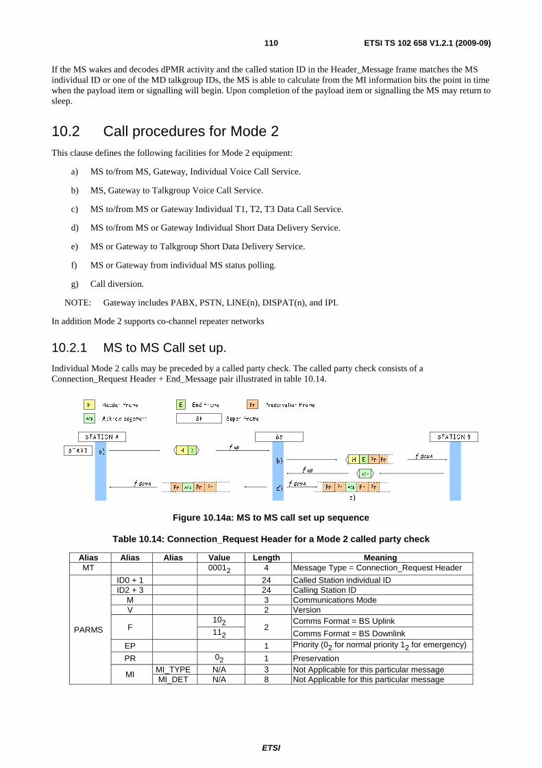
ETSI
ETSI TS 102 658 V1.2.1 (2009-09)110
If the MS wakes and decodes dPMR activity and the called station ID in the Header_Message frame matches the MS individual ID or one of the MD talkgroup IDs, the MS is able to calculate from the MI information bits the point in time when the payload item or signalling will begin. Upon completion of the payload item or signalling the MS may return to sleep.
10.2 Call procedures for Mode 2 This clause defines the following facilities for Mode 2 equipment:
a) MS to/from MS, Gateway, Individual Voice Call Service.
b) MS, Gateway to Talkgroup Voice Call Service.
c) MS to/from MS or Gateway Individual T1, T2, T3 Data Call Service.
d) MS to/from MS or Gateway Individual Short Data Delivery Service.
e) MS or Gateway to Talkgroup Short Data Delivery Service.
f) MS or Gateway from individual MS status polling.
g) Call diversion.
NOTE: Gateway includes PABX, PSTN, LINE(n), DISPAT(n), and IPI.
In addition Mode 2 supports co-channel repeater networks
10.2.1 MS to MS Call set up.
Individual Mode 2 calls may be preceded by a called party check. The called party check consists of a Connection_Request Header + End_Message pair illustrated in table 10.14.
H Header F rame
AC K A ck now ledgement Sup er F rameSF
End F rameE Pr Preservation F rame
ST A R T H E
S T A T IO N A BS ST A T IO N B
AC K
f up
f up
f dow nPrH E Pr
a )
b)
c )
d)f down
Pr Pr PrPr A CKf down
Pr PrAC K Pr
Figure 10.14a: MS to MS call set up sequence
Table 10.14: Connection_Request Header for a Mode 2 called party check
Alias Alias Alias Value Length Meaning MT 00012 4 Message Type = Connection_Request Header
PARMS
ID0 + 1 24 Called Station individual ID ID2 + 3 24 Calling Station ID
M 3 Communications Mode V 2 Version
F 102
2 Comms Format = BS Uplink
112 Comms Format = BS Downlink
EP 1 Priority (02 for normal priority 12 for emergency)
PR 02 1 Preservation
MI MI_TYPE N/A 3 Not Applicable for this particular message MI_DET N/A 8 Not Applicable for this particular message
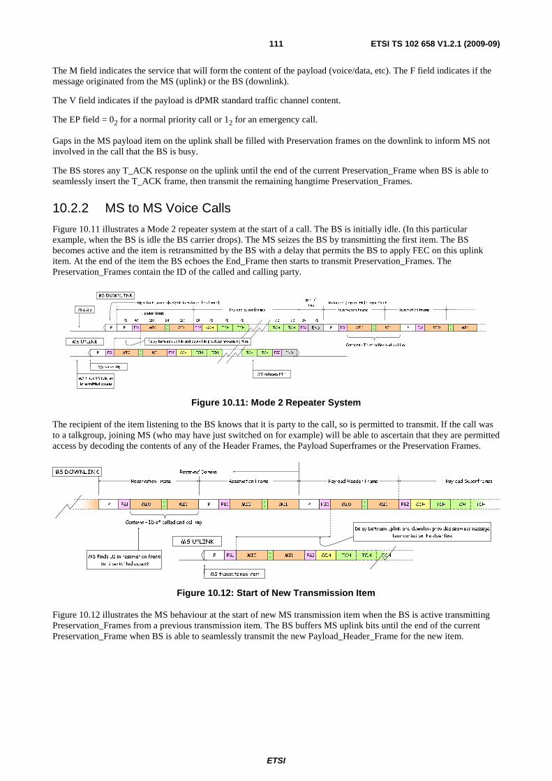
ETSI
ETSI TS 102 658 V1.2.1 (2009-09)111
The M field indicates the service that will form the content of the payload (voice/data, etc). The F field indicates if the message originated from the MS (uplink) or the BS (downlink).
The V field indicates if the payload is dPMR standard traffic channel content.
The EP field = 02 for a normal priority call or 12 for an emergency call.
Gaps in the MS payload item on the uplink shall be filled with Preservation frames on the downlink to inform MS not involved in the call that the BS is busy.
The BS stores any T_ACK response on the uplink until the end of the current Preservation_Frame when BS is able to seamlessly insert the T_ACK frame, then transmit the remaining hangtime Preservation_Frames.
10.2.2 MS to MS Voice Calls
Figure 10.11 illustrates a Mode 2 repeater system at the start of a call. The BS is initially idle. (In this particular example, when the BS is idle the BS carrier drops). The MS seizes the BS by transmitting the first item. The BS becomes active and the item is retransmitted by the BS with a delay that permits the BS to apply FEC on this uplink item. At the end of the item the BS echoes the End_Frame then starts to transmit Preservation_Frames. The Preservation_Frames contain the ID of the called and calling party.
P MI0 MI1 CCH TCH TCH TCH TCH
FS2 CCH TCH TCH TCH TCH
72 48 120 24 120 7224 72 72
END
72 72
FS3
7224
ENDFS3
MS releases PTT
MS UPLINK
BS DOWNLINK
BS IDLE
MS finds BS idle so
is permitted access
MS seizes RE
FS2FS1
Payload Superframes
MI1P MI0
CC
FS1
Header 80mS
Delay between uplink and downlink provides processing time
f FEC
P
RE asserts preamble ASAP to reserve the channel
CC
Reserved Domain
Contains - ID of called and callling
Hold timer starts
MI1MI0FS1CC MI1MI0FS1
CC
End of
ItemReservation Frame Reservation Frame
P P
Figure 10.11: Mode 2 Repeater System
The recipient of the item listening to the BS knows that it is party to the call, so is permitted to transmit. If the call was to a talkgroup, joining MS (who may have just switched on for example) will be able to ascertain that they are permitted access by decoding the contents of any of the Header Frames, the Payload Superframes or the Preservation Frames.
TCH
TCH
Reserved Domain
Contains - ID of called and callling
MI1MI0FS1CC MI1MI0FS1
CC FS1
Reservation Frame Reservation Frame
P MI0 MI1 CCH TCH TCH
MS UPLINK
MS transmits new item
FS2FS1CC
Delay between uplink and downlink provides seamless message
boundaries on the downlink
FS2 CCH TCH TCH
Payload Superframes
MI1MI0CC
Payload Header Frame
MS finds ID in reservation frame
so is permitted access
BS DOWNLINK
PPP
Figure 10.12: Start of New Transmission Item
Figure 10.12 illustrates the MS behaviour at the start of new MS transmission item when the BS is active transmitting Preservation_Frames from a previous transmission item. The BS buffers MS uplink bits until the end of the current Preservation_Frame when BS is able to seamlessly transmit the new Payload_Header_Frame for the new item.
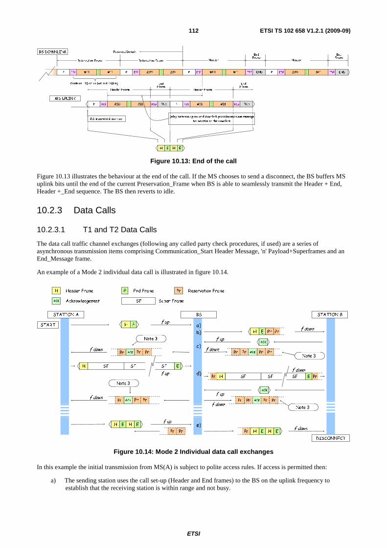
ETSI
ETSI TS 102 658 V1.2.1 (2009-09)112
Reserved Domain
Contains - ID of called and callling
MI1MI0FS1CC MI1MI0FS1
CC FS1
Reservation Frame Reservation Frame
MI1MI0CC
Header
BS DOWNLINK
P MI0 MI1 END
MS transmits disconnect
FS3FS1CC
ENDFS3 ENDFS3
Header Frame
ENDFS3
PPP
P MI0 MI1FS1CC
FrameEnd
Header FrameFrameEnd
Delay between uplink and downlink provides seamless message
boundaries on the downlink
FS1 MI1MI0CC
Header
P
FrameEnd
FrameEnd
H E H E
MS UPLINK
Figure 10.13: End of the call
Figure 10.13 illustrates the behaviour at the end of the call. If the MS chooses to send a disconnect, the BS buffers MS uplink bits until the end of the current Preservation_Frame when BS is able to seamlessly transmit the Header + End, Header +_End sequence. The BS then reverts to idle.
10.2.3 Data Calls
10.2.3.1 T1 and T2 Data Calls
The data call traffic channel exchanges (following any called party check procedures, if used) are a series of asynchronous transmission items comprising Communication_Start Header Message, 'n' Payload+Superframes and an End_Message frame.
An example of a Mode 2 individual data call is illustrated in figure 10.14.
H Header Frame
ACK Acknowledgement Super FrameSF
End FrameE Pr Reservation Frame
START H E
SFH SF SF E
STATION A BS
DISCONNECT
STATION B
ACK
ACK
f up
f up
f up
f up
f downPrH E Pr
PrSFH SF SF E
f down
Pr
f down
a)
b)
c)
d)
f downPr Pr PrPr ACK
f down
f down
Note 3
Note 3
Note 3
Pr PrACK Pr
H E H E
Pr PrACK Pr Pr Pr PrPr ACK
f up
f downPr H E H Ef)PrPr
Note 3
e)
Figure 10.14: Mode 2 Individual data call exchanges
In this example the initial transmission from MS(A) is subject to polite access rules. If access is permitted then:
a) The sending station uses the call set-up (Header and End frames) to the BS on the uplink frequency to establish that the receiving station is within range and not busy.

ETSI
ETSI TS 102 658 V1.2.1 (2009-09)113
b) The BS retransmits the call set-up on the downlink frequency to the receiving station. The BS protects the traffic channel against access by MS not involved in the call by transmitting preservation frames.
c) When the receiving station has acknowledged with a T_ACK, the T_ACK is repeated by the BS to the sending station. The sending station commences to send the data in 4 superframe bursts. After each burst the receiving station decodes and error checks the data and if there are no errors a positive T_ACK is sent. If errors are detected then a negative T_ACK would be sent and the sending station would repeat that transmission.
d) The BS retransmits the T_ACK on the downlink.
e) When all the data has been transmitted and positively acknowledged the sending station sends a disconnect request through the BS to show that the transaction is complete. The BS then drops its carrier.
NOTE 1: There is an inherent delay between information received by the BS on the uplink channel and the BS retransmitting the information on the downlink channel.
NOTE 2: In the gap between transmission items, the Base Station transmits preservation frames to preserve the system for the call.
NOTE 3: During the call the transmission from the BS is continuous. Preservation frames are transmitted when there are no MS originated messages to transmit. Unless an MS is transmitting, frames may be received that are directed to the other party. This is illustrated in figure 4.22 in the acknowledgement frames.
For a data call to a talkgroup, acknowledgements are not transmitted.
If the sending MS does not receive an acknowledgement, the data item may be repeated or the sender may send an RLA (Repeat Last Ack) message.
10.2.3.2 T3 (Packet) Data Calls
T3 (Packet) data calls are always individual calls as each packet is acknowledged. MS may choose to send a called party check before the first packet data item is transmitted. The packet items follow the same format as clause 10.1.3.2. Uplink and Downlink headers are distinguished by the F field (102 for uplink and 112 for downlink).
10.2.3.3 MS to MS Status request and responses
These consist of a Status_Request + End frame pair. Called parties receiving a status request shall reply with a Status_Response message.
The BS shall insert preservation frames immediately after the Status_Request + End frame pair has been re-transmitted on the downlink preserving the channel for the polled party acknowledgement. The BS buffers any status response from the polled party until the end of the current Preservation_Frame when BS is able to seamlessly transmit the H+E frame pair of the status response. At the end of the transaction the BS shall return to idle.
10.2.3.4 MS to MS Short Data
An MS may send a short data message to an MS or talkgroup. The UDT protocol enables the sender to define the format of the data including binary, BCD, text, byte and NMEA. These formats are described in clause 5.6.
If the short data destination is a talkgroup, an acknowledgement is not transmitted by the recipient(s).
A short data message does not create a logical connection so there is no need to send a disconnect.
The burst sequence is a Connection_Request header + 1 to 4 Appended_Data messages + END frame.
The Connection_Request from the calling MS is coded as table 10.15. The BS shall transmit the burst on the downlink substituting F = 112 for the downlink. The BS shall insert preservation frames on the downlink until the transaction is
complete then the BS shall revert to idle.
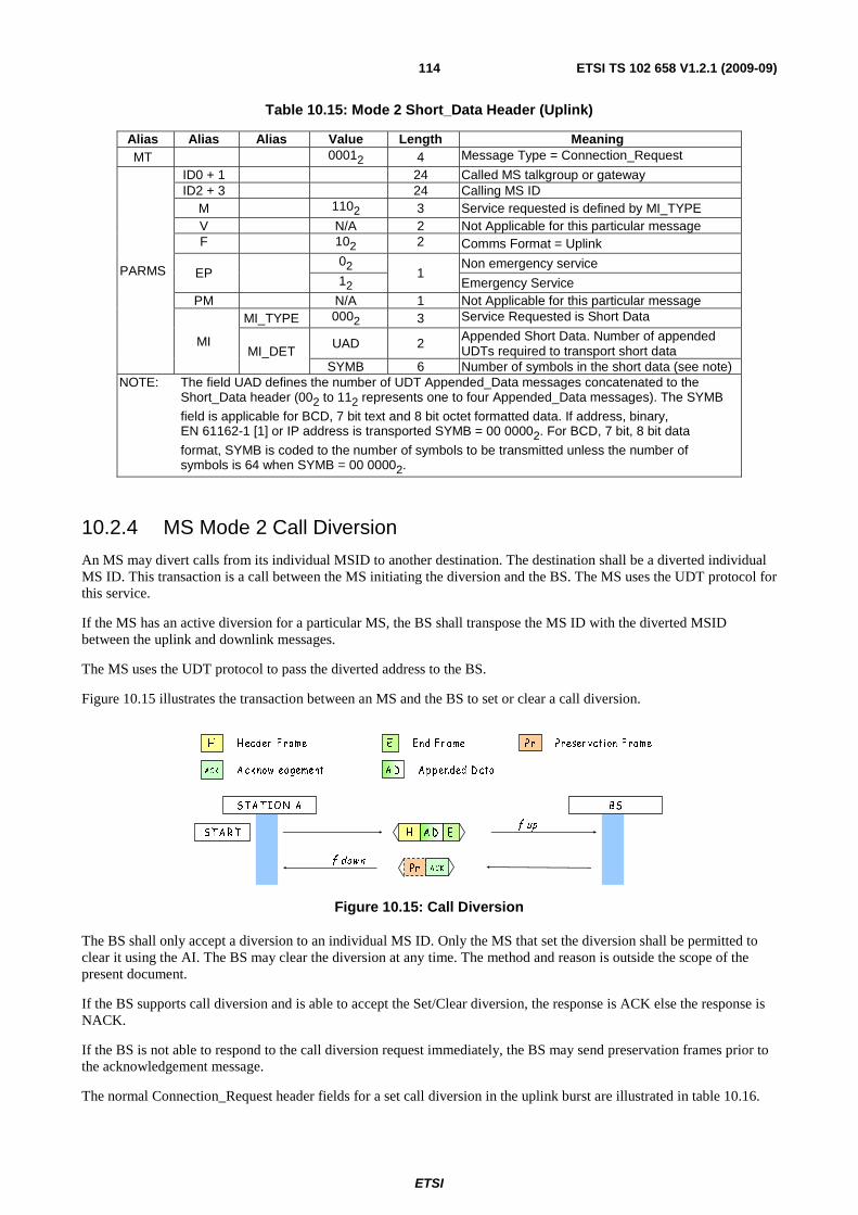
ETSI
ETSI TS 102 658 V1.2.1 (2009-09)114
Table 10.15: Mode 2 Short_Data Header (Uplink)
Alias Alias Alias Value Length Meaning MT 00012 4 Message Type = Connection_Request
PARMS
ID0 + 1 24 Called MS talkgroup or gateway ID2 + 3 24 Calling MS ID
M 1102 3 Service requested is defined by MI_TYPE V N/A 2 Not Applicable for this particular message F 102 2 Comms Format = Uplink
EP 02
1 Non emergency service
12 Emergency Service PM N/A 1 Not Applicable for this particular message
MI
MI_TYPE 0002 3 Service Requested is Short Data
MI_DET UAD 2 Appended Short Data. Number of appended
UDTs required to transport short data SYMB 6 Number of symbols in the short data (see note)
NOTE: The field UAD defines the number of UDT Appended_Data messages concatenated to the Short_Data header (002 to 112 represents one to four Appended_Data messages). The SYMB
field is applicable for BCD, 7 bit text and 8 bit octet formatted data. If address, binary, EN 61162-1 [1] or IP address is transported SYMB = 00 00002. For BCD, 7 bit, 8 bit data
format, SYMB is coded to the number of symbols to be transmitted unless the number of symbols is 64 when SYMB = 00 00002.
10.2.4 MS Mode 2 Call Diversion
An MS may divert calls from its individual MSID to another destination. The destination shall be a diverted individual MS ID. This transaction is a call between the MS initiating the diversion and the BS. The MS uses the UDT protocol for this service.
If the MS has an active diversion for a particular MS, the BS shall transpose the MS ID with the diverted MSID between the uplink and downlink messages.
The MS uses the UDT protocol to pass the diverted address to the BS.
Figure 10.15 illustrates the transaction between an MS and the BS to set or clear a call diversion.
H H eader F r ame
ACK A ck now ledgement
End F r ameE Pr Pr eser vation F rame
A D A p p ended D ata
S T A R T
S T A T IO N A BS
f up
f downPr ACK
H EA D
Figure 10.15: Call Diversion
The BS shall only accept a diversion to an individual MS ID. Only the MS that set the diversion shall be permitted to clear it using the AI. The BS may clear the diversion at any time. The method and reason is outside the scope of the present document.
If the BS supports call diversion and is able to accept the Set/Clear diversion, the response is ACK else the response is NACK.
If the BS is not able to respond to the call diversion request immediately, the BS may send preservation frames prior to the acknowledgement message.
The normal Connection_Request header fields for a set call diversion in the uplink burst are illustrated in table 10.16.
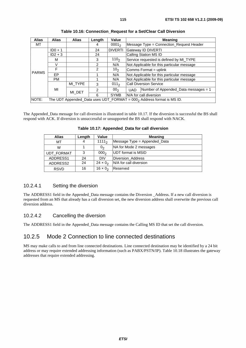
ETSI
ETSI TS 102 658 V1.2.1 (2009-09)115
Table 10.16: Connection_Request for a Set/Clear Call Diversion
Alias Alias Alias Length Value Meaning MT 4 00012 Message Type = Connection_Request Header
PARMS
ID0 + 1 24 DIVERTI Gateway ID DIVERTI ID2 + 3 24 Calling Station MS ID
M 3 1102 Service requested is defined by MI_TYPE V 2 N/A Not Applicable for this particular message F 2 102 Comms Format = uplink
EP 1 N/A Not Applicable for this particular message PM 1 N/A Not Applicable for this particular message
MI
MI_TYPE 3 0112 Call Diversion Service
MI_DET 2 002 UAD Number of Appended_Data messages = 1
6 SYMB N/A for call diversion NOTE: The UDT Appended_Data uses UDT_FORMAT = 0002 Address format is MS ID.
The Appended_Data message for call diversion is illustrated in table 10.17. If the diversion is successful the BS shall respond with ACK. If diversion is unsuccessful or unsupported the BS shall respond with NACK.
Table 10.17: Appended_Data for call diversion
Alias Length Value Meaning MT 4 11112 Message Type = Appended_Data
W 1 02 NA for Mode 2 messages
UDT_FORMAT 3 0002 UDT format is MSID
ADDRESS1 24 DIV Diversion_Address ADDRESS2 24 24 × 02 N/A for call diversion
RSVD 16 16 × 02 Reserved
10.2.4.1 Setting the diversion
The ADDRESS1 field in the Appended_Data message contains the Diversion _Address. If a new call diversion is requested from an MS that already has a call diversion set, the new diversion address shall overwrite the previous call diversion address.
10.2.4.2 Cancelling the diversion
The ADDRESS1 field in the Appended_Data message contains the Calling MS ID that set the call diversion.
10.2.5 Mode 2 Connection to line connected destinations
MS may make calls to and from line connected destinations. Line connected destination may be identified by a 24 bit address or may require extended addressing information (such as PABX/PSTN/IP). Table 10.18 illustrates the gateway addresses that require extended addressing.

ETSI
ETSI TS 102 658 V1.2.1 (2009-09)116
Table 10.18: Matrix for Mode 2 calls to line connected destinations
Type of Call Gateway Extended Addressing
Format of Extended Addressing
Call to the system line connected dispatcher
LINEIn n = 1 to 4 No
Call to the system dispatched
DISPATIn n = 1 to 4 No
Call to the PABX PABXI Yes BCD terminated in DIAL_NULL
Call to the PSTN PSTNI Yes BCD terminated in DIAL_NULL
Call to an IP Destination IPI Yes IPV4 or IPV6
Table 10.18 illustrates the destinations that do not require extended addressing only requiring the gateway address. For destinations that do require extended addressing, this extended addressing is dialling information using BCD digits for PABX and PSTN, or an IPV4/IPV6 address for an IP destination. Destinations that use BCD coding and "*" and "#" characters, the digits symbol table in clause 5.4.11 describes the alphabet.
The method by which an MS builds the burst for a Connection Request is uniform and logical. The steps are illustrated in figure 10.16.
Normal Header+
Appended Data
Extended
Address
Power Save
Header
Power Save
Header
Power Save
Header + + + + END
(a) (b) (c) (d)
Figure 10.16: Burst build-up for a line connected call
The steps to build a call set-up burst are:
a) If necessary powersave messages preceded a normal Connection_Request header.
b) The Connection_Request header contains fields that define the call service requested and if Appended_Data message(s) are necessary. The called ID field contains a gateway ID that indicates the type of line connected equipment that the MS wishes to connect to. Valid gateway IDs are PABXI, PSTNI, LINEI(n), IPI.
c) If the call set-up requires extended address information (such as dialled digits for PSTN), that extended information is encapsulated in an Appended_Data message.
d) Finally the END message completes the call set-up burst.
For a call to a PABX/PSTN destination the format of the Extended Address in an Appended_Data message is BCD.
For a call to an IP destination the format of the Extended Address in an Appended_Data message is IPV4 or IPV6.
Calls set-up to line connected destinations shall begin with a Connection Request using a Connection_Request header. For destinations requiring extended addressing, the Connection_Request header is the header to a UDT Appended_Data message. The Appended_Data messages are described in clause 5.6.
The call set-up to establish a connection between an MS and a line type entity that does not use extended addressing is illustrated in figure 10.17.

ETSI
ETSI TS 102 658 V1.2.1 (2009-09)117
H H eader F rame
ACK A ck now ledgement
End F rameE Pr Preservation F rame
S T A R T
S T A T I O N A B S
f up
f downPr PrACK Pr
H E
Figure 10.17: Call to LINEIn or DISPATIn Gateway
If the call destination requires extended addressing an Appended_Data message is concatenated to the Connection_Request Header. An example of a complete call to a PABX/PSTN destination that requires extended addressing is illustrated in figure 10.17a.
H Header F rame
ACK A cknow ledgement Sup er F rameSF
End F rameE Pr Preservation F rame
D A p p ended D ata
S T A R T
H E H E
ST A T IO N A BS
D ISC O N N EC T
f up
f dow n
H EA D
S F HS F S FE
f dow n
SFH S F S F E
f up
PrACK Pr A nsw er (A C K )
C al led Par ty C heck(a)
C hannel
O ccup ation
End of C al l(d)
(b )
(c)
and up l ink dia l led digits
Figure 10.17a: Call to PSTN/PABX
Referring to figure 10.17a the call set-up procedure is:
The calling MS selects the destination PABX extension or PSTN number.
a) The MS sends a called Connection_Request header setting the destination ID to the gateway address. The destination ID is PABXI for a PABX extension or PSTNI for a PSTN destination. This step creates the call connection. The channel is protected by preservation frames transmitted by the BS. The dialled digits are carried in the Appended_Data message.
b) A positive acknowledgement is sent from the BS.
c) During channel occupation the voice path from the gateway to the MS is continuous. The voice path from the MS to the gateway is active when the MS is transmitting a voice item.
d) The MS has disconnected the call. If the BS is able to detect the line connected party has hung up, the BS shall send the disconnect message.

ETSI
ETSI TS 102 658 V1.2.1 (2009-09)118
When the BS receives the connection request it shall protect the channel by transmitting Preservation frames on the downlink. When the BS has processed the uplink burst, the BS shall acknowledge the call by transmitting an appropriate acknowledgement. If the BS is able to connect the call requested, the acknowledgement shall be ACK. If the BS is unable to connect the call the acknowledgement shall be a NACK and the BS shall enter the idle state.
The payload and disconnect messages shall use the called party = gateway ident to identify the users of the channel.
10.2.5.1 Voice Call Connection_Request message
The normal Connection_Request header fields in the MS uplink burst are set as table 10.19.
Table 10.19: Connection_Request for call to a line connected destination
Alias Alias Alias Length Value Meaning MT 4 00012 Message Type = Connection_Request Header
PARMS
ID0 + 1 24 Gateway ID PABXI, PSTNI, LINEIn, DISPATIn ID2 + 3 24 Calling Station MS ID
M 3 Call Service - Voice/data, etc. V 2 Payload TCH content (if standard = 002)
F 2 102 Comms Format = uplink
EP 1 02 Normal Priority = 02 Emergency Priority = 12
PM 1 N/A Not Applicable for this particular message
MI
MI_TYPE 3
0002 Appended_Data messages not required
0012 Appended_Data Message(s) needed for this call
0102 to
1102 Reserved
1112 Not a normal frame. This is a powersave frame
MI_DET 1 002 UAD Number of Appended_Data messages
needed to transport dialling digits 6 N/A Not Applicable for this particular message
For a call to LINEI(n) or DISPATI(n) the Appended_Data message is not required. For a call to the PSTN/PABX the Appended_Data message(s) carry the dialled digits.
10.2.5.2 Call Matrix for calls to line connected destinations
Table 10.20 illustrates the fields for a Connection_Request header for line connected destinations described in the present document.
Table 10.20: Message matrix for calls to line connected destinations
Call to ID0 + 1 MI_TYPE MI_DET
Appended_Data UAD Dialled Digits
Line(n) LINEIn 0002 002 No
Dispatcher(n) DISPATIn 0002 002 No
PABX PABXI 0012
002 Digits = 1 to 16
Yes UDP_FORMAT = 0102
012 Digits = 17 to 32
PSTN PSTNI 002 Digits = 1 to 16 012 Digits = 17 to 32
IP (IPV4) IPI 0012
002 Yes UDP_FORMAT = 1112
IP (IPV6) 012
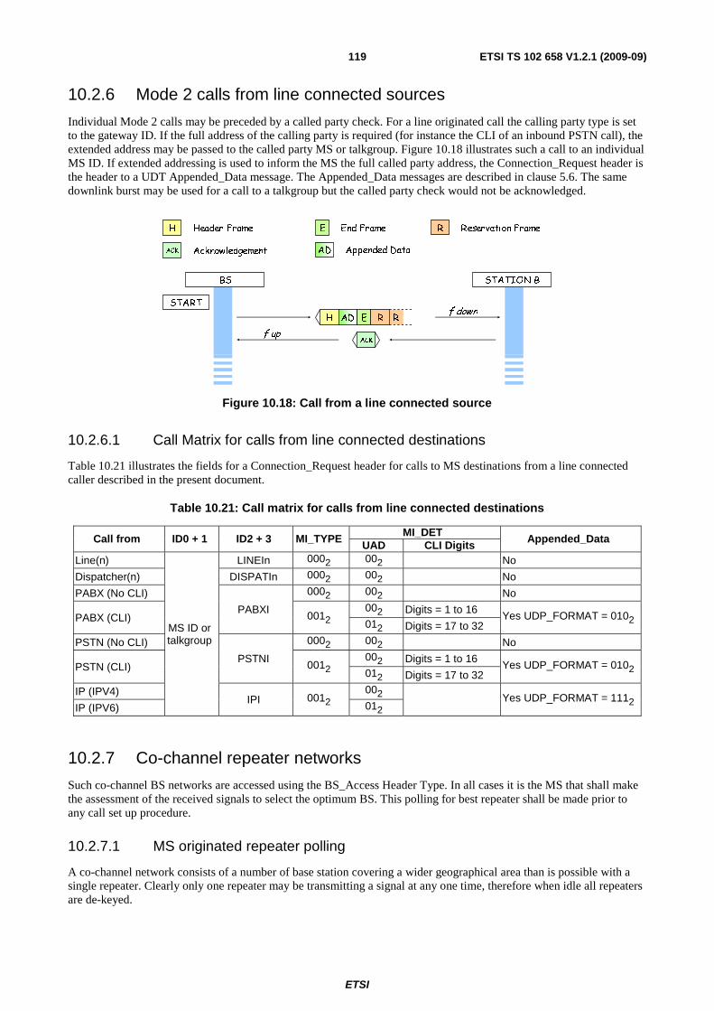
ETSI
ETSI TS 102 658 V1.2.1 (2009-09)119
10.2.6 Mode 2 calls from line connected sources
Individual Mode 2 calls may be preceded by a called party check. For a line originated call the calling party type is set to the gateway ID. If the full address of the calling party is required (for instance the CLI of an inbound PSTN call), the extended address may be passed to the called party MS or talkgroup. Figure 10.18 illustrates such a call to an individual MS ID. If extended addressing is used to inform the MS the full called party address, the Connection_Request header is the header to a UDT Appended_Data message. The Appended_Data messages are described in clause 5.6. The same downlink burst may be used for a call to a talkgroup but the called party check would not be acknowledged.
H Header Frame
ACK Acknowledgement
End FrameE R Reservation Frame
AD Appended Data
START
BS STATION B
ACKf up
f downRH E RAD
Figure 10.18: Call from a line connected source
10.2.6.1 Call Matrix for calls from line connected destinations
Table 10.21 illustrates the fields for a Connection_Request header for calls to MS destinations from a line connected caller described in the present document.
Table 10.21: Call matrix for calls from line connected destinations
Call from ID0 + 1 ID2 + 3 MI_TYPE MI_DET
Appended_Data UAD CLI Digits
Line(n)
MS ID or talkgroup
LINEIn 0002 002 No
Dispatcher(n) DISPATIn 0002 002 No
PABX (No CLI)
PABXI
0002 002 No
PABX (CLI) 0012 002 Digits = 1 to 16
Yes UDP_FORMAT = 0102 012 Digits = 17 to 32
PSTN (No CLI)
PSTNI
0002 002 No
PSTN (CLI) 0012 002 Digits = 1 to 16
Yes UDP_FORMAT = 0102 012 Digits = 17 to 32
IP (IPV4) IPI 0012
002 Yes UDP_FORMAT = 1112
IP (IPV6) 012
10.2.7 Co-channel repeater networks
Such co-channel BS networks are accessed using the BS_Access Header Type. In all cases it is the MS that shall make the assessment of the received signals to select the optimum BS. This polling for best repeater shall be made prior to any call set up procedure.
10.2.7.1 MS originated repeater polling
A co-channel network consists of a number of base station covering a wider geographical area than is possible with a single repeater. Clearly only one repeater may be transmitting a signal at any one time, therefore when idle all repeaters are de-keyed.

ETSI
ETSI TS 102 658 V1.2.1 (2009-09)120
An MS shall select a repeater that provides the best signal quality before initiating the call to the called party. To identify separate BSs in the co-channel network, each BS is given a gateway address for the purposes of co-channel operation. Fifteen co channel addresses are defined in the present document - COCHI1 to COCHI15.
Figure 10.19 illustrates a four repeater Mode 2 network. MS may choose to select the repeater that provides the best grade of service by the following process:
• MS shall transmit a BS_Access H + End frame (Message type = 10102, MI_TYPE=0002) to Gateway ID
COCHI0. Each repeater receiving this call shall respond in sequence with a BS_Access response (MI_TYPE = 0002) + End that is transmitted after a time delay calculated from its own COCHIn. The MS with
the highest COCHIn shall transmit its polling response first, then the other repeaters counting down in turn.
• The MS shall then evaluate the quality of each received response and use the best signal to identify the repeater that it shall use. (MS may use RSSI other method to measure the quality of the responses).
• MS shall determine from any received replies when the final (COCHI = 1) transmission in the sequence will occur, and the downlink channel may be assumed to be free. The BS originated BS_Access Header demands an acknowledgement. The MS selects the COCH BS that will be used for the call and sends a acknowledgement with ID1 + 0 set to the co-channel gateway address that will be used for the call. (In this example BS3 has been selected).
• The selected BS then asserts its carrier and transmits preservation frames until the MS makes its call set-up or payload transmission. (or the BS hang timer expires).
The call set up and call exchanges are then exactly as for normal repeater calls.
Relative Frame Number
MS UPLINK
BS 4 DOWNLINK
BS 3 DOWNLINK
BS 2 DOWNLINK
BS 1 DOWNLINK
1 2 3 4 5 6 7 8 9 10 11 12
BS Access header
EH AK
PrPr
EH
EH
EH
EH
BS Access
response
BS Access
response
BS Access
response
BS Access
response
MS
Acknowledgement
Figure 10.19: MS polling of a 4 repeater network
In a co-channel network, each call shall be preceded by the BS selection. It shall not be possible to seize a BS without this selection process. If the BS times out and becomes idle (de-keys), the selection process shall be repeated.
NOTE: The BS hang time is configurable. For co-channel networks designers may choose to set a BS hang time that is different for certain call services. For example voice services may have a longer BS hang time than data services.
When the selected BS assets its carrier and transmits Preservation frames, the address of the called party is not known. The Preservation messages shall therefore contain the address of the calling party and DUMMYI until the BS is able to determine the called party address(or gateway) whereupon it shall substitute the legitimate users of the channel.

ETSI
ETSI TS 102 658 V1.2.1 (2009-09)121
10.2.7.1.1 Description of the messages
The initial BS_Access_Header is illustrated in table 10.22 followed by the BS_Access Response and T_ACK message.
Table 10.22: BS_Access Header, Response and T_ACK for Co Channel Access
Alias Alias Alias Value Length Meaning
MT 10102 4 Message Type = BS_Access header and response
PARMS
ID0 + 1 24 Gateway COCHI0 ID2 + 3 24 Calling MS ID
M N/A 3 Not Applicable for this particular message V N/A 2 Not Applicable for this particular message F 102 2 Comms Format = BS Uplink
EP N/A 1 Not Applicable for this particular message PM N/A 1 Not Applicable for this particular message
MI MI_TYPE
0002 3
No Appended_Data
other Reserved MI_DET N/A 8 Not Applicable for this particular message
Alias Alias Alias Value Length Meaning
MT 10102 4 Message Type = BS_Access header and response
PARMS
ID0 + 1 24 MS ID ID2 + 3 24 Gateway COCHIn
M N/A 3 Not Applicable for this particular message V N/A 2 Not Applicable for this particular message F 112 2 Comms Format = BS Downlink
EP N/A 1 Not Applicable for this particular message PM N/A 1 Not Applicable for this particular message
MI MI_TYPE
0002 3
No Appended_Data
other Reserved MI_DET N/A 8 Not Applicable for this particular message
Alias Alias Alias Length Value Meaning MT 4 00112 Mess_Type = T_ACK
PARMS
ID0 + 1 24 Gateway address of the chosen BS ID2 + 3 24 MSID
M N/A 1 Not Applicable for this particular message V N/A 1 Not Applicable for this particular message F 102 2 Comms Format = BS Uplink
EP N/A 1 Not Applicable for this particular message PM 1 N/A Not Applicable for this particular message
MI MI_TYPE 3 0012 ACK (Rx OK)
MI_DET 8 Reason
10.2.7.2 BS originated repeater polling
An individual call to an MS may originate from a line connected source. In this case the network shall determine the best BS for the call by polling the called party from each BS in turn.
Figure 10.20 illustrates a four repeater Mode 2 network.
The repeater with the highest COCHIn shall transmit a BS_Access response +End frame (MI_TYPE = 0002). The other
BS shall transmit a BS_Access response after a time delay calculated from its own COCHIn in turn.
MS shall determine from any received replies when the final (COCHI = 1) transmission in the sequence will occur, and the downlink channel may be assumed to be free. The BS originated BS_Access Header demands an acknowledgement.
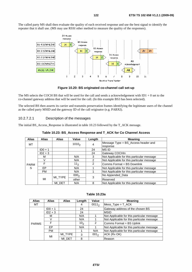
ETSI
ETSI TS 102 658 V1.2.1 (2009-09)122
The called party MS shall then evaluate the quality of each received response and use the best signal to identify the repeater that it shall use. (MS may use RSSI other method to measure the quality of the responses).
BS 4 DOWNLINK
BS 3 DOWNLINK
BS 2 DOWNLINK
BS 1 DOWNLINK
MS(B) UPLINK
Relative Frame Number
1 2 3 4 5 6 7 8 9 10 11
EH
AK
PrPrEH
EH
EH
BS Access
response
BS Access
response
BS Access
response
MS
Acknowledgement
BS Access
response
Figure 10.20: BS originated co-channel call set-up
The MS selects the COCH BS that will be used for the call and sends a acknowledgement with ID1 + 0 set to the co-channel gateway address that will be used for the call. (In this example BS3 has been selected).
The selected BS then asserts its carrier and transmits preservation frames identifying the legitimate users of the channel as the called party MSID and the gateway ID of the call originator (e.g. PABXI).
10.2.7.2.1 Description of the messages
The initial BS_Access_Response is illustrated in table 10.23 followed by the T_ACK message.
Table 10.23: BS_Access Response and T_ACK for Co Channel Access
Alias Alias Alias Value Length Meaning
MT 10102 4 Message Type = BS_Access header and response
PARMS
ID0 + 1 24 MS ID ID2 + 3 24 Gateway COCHIn
M N/A 3 Not Applicable for this particular message V N/A 2 Not Applicable for this particular message F 112 2 Comms Format = BS Downlink
EP N/A 1 Not Applicable for this particular message PM N/A 1 Not Applicable for this particular message
MI MI_TYPE
0002 3
No Appended_Data
other Reserved MI_DET N/A 8 Not Applicable for this particular message
Table 10.23a
Alias Alias Alias Length Value Meaning MT 4 00112 Mess_Type = T_ACK
PARMS
ID0 + 1 24 Gateway address of the chosen BS ID2 + 3 24 MSID
M N/A 1 Not Applicable for this particular message V N/A 1 Not Applicable for this particular message F 102 2 Comms Format = BS Uplink
EP N/A 1 Not Applicable for this particular message PM 1 N/A Not Applicable for this particular message
MI MI_TYPE 3 0012 ACK (Rx OK)
MI_DET 8 Reason

ETSI
ETSI TS 102 658 V1.2.1 (2009-09)123
10.2.7.3 Access and Response timing
Figure 10.21 illustrates the timing from which each message in the co-channel network polling sequence is timed.
EH
80mS 20mS EH
80mS 20mS EH
80mS 20mSAK
80mS
80mSA
B
C
D
80mS
80mS
Figure 10.21: Co-Channel BS/MS timing
"A" is the first message from which the timing for subsequent messages shall be timed.
For MS originated repeater polling "A" is the BS Access Header on the uplink. "B" is the BS Access response with the highest COCHIn in the network. "C" is the BS with ID COCHI1 and "D" is the acknowledgement from MS(A).
For BS originated polling "A" is the BS Access response with the highest COCHIn in the network. "B" is COCHIn-1, "C" is the BS with ID COCHI1 and "D" is the acknowledgement from MS(B).
Although Mode 2 operation is asynchronous, for the purposes of co-channel polling, messages shall be timed into slots equal to a message frame as illustrated in figure 10.21.
NOTE: In a practical environment an MS listening to the BS Access Response messages, not all messages may be received because one or more BSs may be out of range. The BS is however able to calculate when the acknowledgement is sent form the COCHIn embedded in the message if it receives any one of the BS responses.
10.3 Call Procedures for Mode 3 The channel access mechanism for Mode 3 systems are described in clause 12.3. Channel access is synchronous and aligned to a beacon channel frame structure.
Access to Mode 3 Services from MS shall be by random access using the random access protocol described in clause 12.3.7. The B_RAND random access frame contains all parameters necessary to signify the particular Mode 3 service requested.
Mode 3 equipment may support the following facilities:
• MS to/from MS or Gateway Individual Voice Call Service.
• MS or Gateway Voice Call Service to talkgroup.
• MS to/from MS or Gateway Individual Data Call Service.
• MS or Gateway Data Call Service to talkgroup.
• MS to/from MS/Gateway Individual Short Data Delivery Service.
• MS or Gateway Short Data Delivery Service to talkgroup.
• MS from MS or Gateway Individual data polling.
• Call Diversion Service.
• MS stun Service.
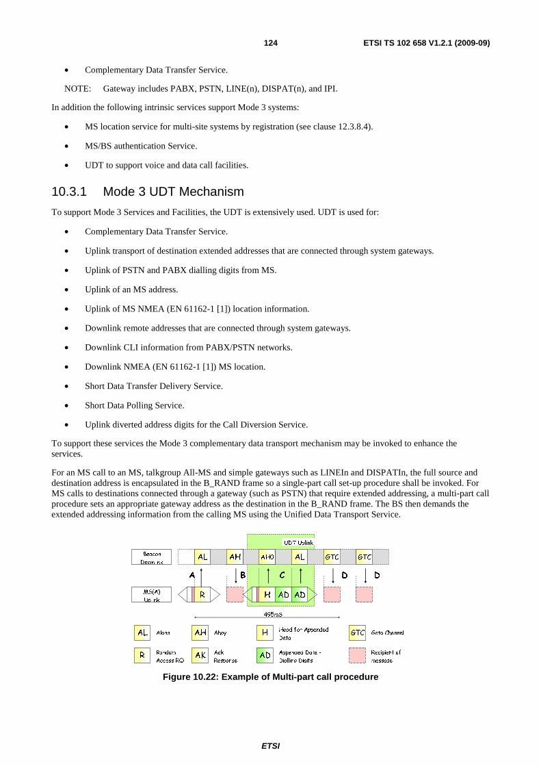
ETSI
ETSI TS 102 658 V1.2.1 (2009-09)124
• Complementary Data Transfer Service.
NOTE: Gateway includes PABX, PSTN, LINE(n), DISPAT(n), and IPI.
In addition the following intrinsic services support Mode 3 systems:
• MS location service for multi-site systems by registration (see clause 12.3.8.4).
• MS/BS authentication Service.
• UDT to support voice and data call facilities.
10.3.1 Mode 3 UDT Mechanism
To support Mode 3 Services and Facilities, the UDT is extensively used. UDT is used for:
• Complementary Data Transfer Service.
• Uplink transport of destination extended addresses that are connected through system gateways.
• Uplink of PSTN and PABX dialling digits from MS.
• Uplink of an MS address.
• Uplink of MS NMEA (EN 61162-1 [1]) location information.
• Downlink remote addresses that are connected through system gateways.
• Downlink CLI information from PABX/PSTN networks.
• Downlink NMEA (EN 61162-1 [1]) MS location.
• Short Data Transfer Delivery Service.
• Short Data Polling Service.
• Uplink diverted address digits for the Call Diversion Service.
To support these services the Mode 3 complementary data transport mechanism may be invoked to enhance the services.
For an MS call to an MS, talkgroup All-MS and simple gateways such as LINEIn and DISPATIn, the full source and destination address is encapsulated in the B_RAND frame so a single-part call set-up procedure shall be invoked. For MS calls to destinations connected through a gateway (such as PSTN) that require extended addressing, a multi-part call procedure sets an appropriate gateway address as the destination in the B_RAND frame. The BS then demands the extended addressing information from the calling MS using the Unified Data Transport Service.
AL AH AL GTC GTC
495mS
AH0
UDT Uplink
AL Aloha AH Ahoy HHead for Appended
Data
Appended Data -
Dialling DigitsAK
Ack
ResponseADR
Random
Access RQ
Recipient of
message
GTC Goto Channel
MS(A)
Uplink
Beacon
Downlink
BA C D D
R H AD AD
Figure 10.22: Example of Multi-part call procedure
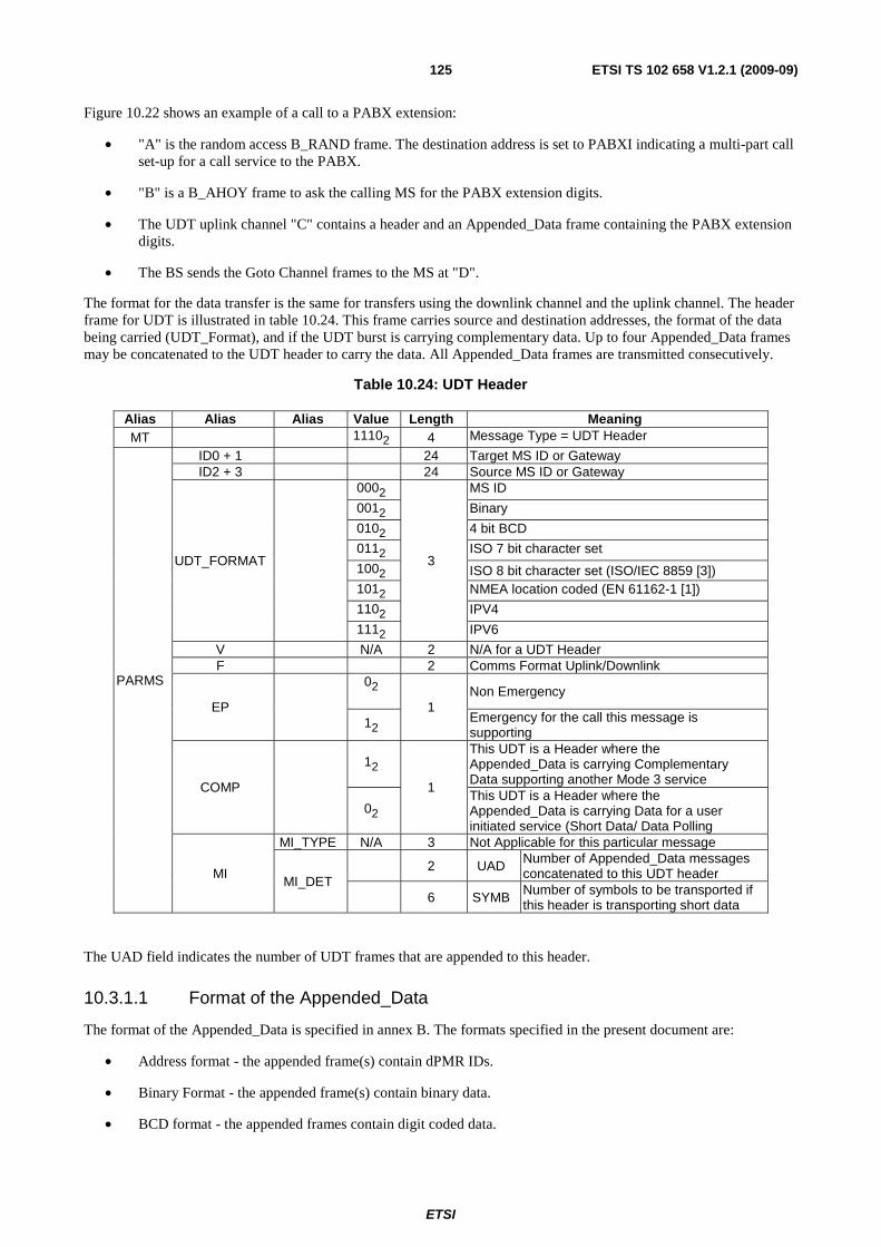
ETSI
ETSI TS 102 658 V1.2.1 (2009-09)125
Figure 10.22 shows an example of a call to a PABX extension:
• "A" is the random access B_RAND frame. The destination address is set to PABXI indicating a multi-part call set-up for a call service to the PABX.
• "B" is a B_AHOY frame to ask the calling MS for the PABX extension digits.
• The UDT uplink channel "C" contains a header and an Appended_Data frame containing the PABX extension digits.
• The BS sends the Goto Channel frames to the MS at "D".
The format for the data transfer is the same for transfers using the downlink channel and the uplink channel. The header frame for UDT is illustrated in table 10.24. This frame carries source and destination addresses, the format of the data being carried (UDT_Format), and if the UDT burst is carrying complementary data. Up to four Appended_Data frames may be concatenated to the UDT header to carry the data. All Appended_Data frames are transmitted consecutively.
Table 10.24: UDT Header
Alias Alias Alias Value Length Meaning MT 11102 4 Message Type = UDT Header
PARMS
ID0 + 1 24 Target MS ID or Gateway ID2 + 3 24 Source MS ID or Gateway
UDT_FORMAT
0002
3
MS ID
0012 Binary
0102 4 bit BCD
0112 ISO 7 bit character set
1002 ISO 8 bit character set (ISO/IEC 8859 [3]) 1012 NMEA location coded (EN 61162-1 [1])
1102 IPV4
1112 IPV6
V N/A 2 N/A for a UDT Header F 2 Comms Format Uplink/Downlink
EP
02 1
Non Emergency
12 Emergency for the call this message is supporting
COMP
12
1
This UDT is a Header where the Appended_Data is carrying Complementary Data supporting another Mode 3 service
02 This UDT is a Header where the Appended_Data is carrying Data for a user initiated service (Short Data/ Data Polling
MI
MI_TYPE N/A 3 Not Applicable for this particular message
MI_DET 2 UAD Number of Appended_Data messages
concatenated to this UDT header
6 SYMB Number of symbols to be transported if this header is transporting short data
The UAD field indicates the number of UDT frames that are appended to this header.
10.3.1.1 Format of the Appended_Data
The format of the Appended_Data is specified in annex B. The formats specified in the present document are:
• Address format - the appended frame(s) contain dPMR IDs.
• Binary Format - the appended frame(s) contain binary data.
• BCD format - the appended frames contain digit coded data.
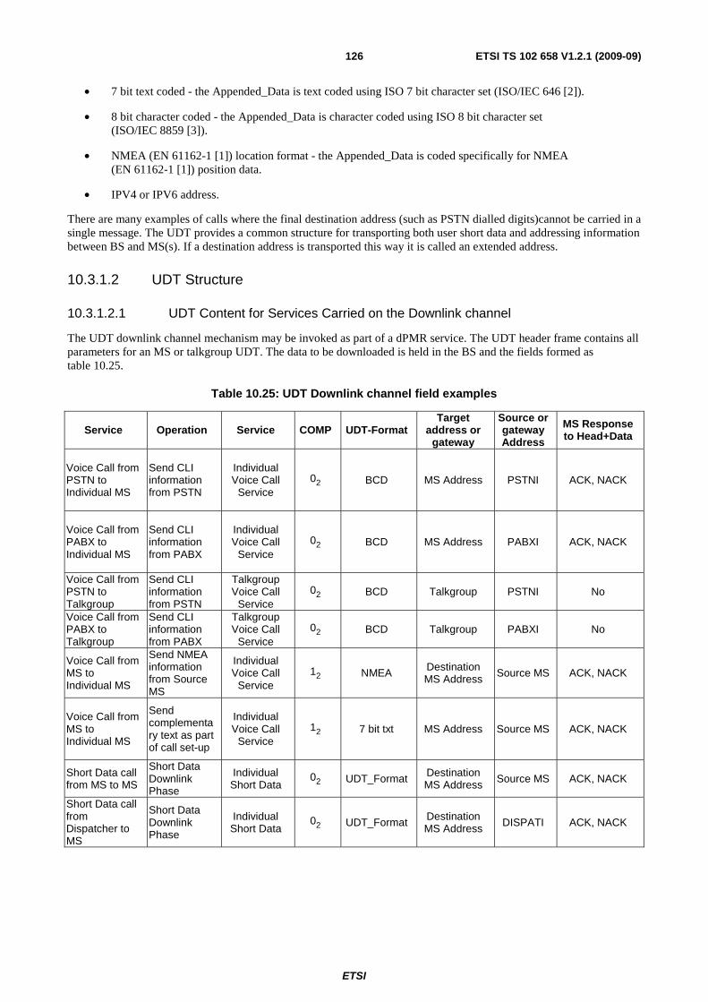
ETSI
ETSI TS 102 658 V1.2.1 (2009-09)126
• 7 bit text coded - the Appended_Data is text coded using ISO 7 bit character set (ISO/IEC 646 [2]).
• 8 bit character coded - the Appended_Data is character coded using ISO 8 bit character set (ISO/IEC 8859 [3]).
• NMEA (EN 61162-1 [1]) location format - the Appended_Data is coded specifically for NMEA (EN 61162-1 [1]) position data.
• IPV4 or IPV6 address.
There are many examples of calls where the final destination address (such as PSTN dialled digits)cannot be carried in a single message. The UDT provides a common structure for transporting both user short data and addressing information between BS and MS(s). If a destination address is transported this way it is called an extended address.
10.3.1.2 UDT Structure
10.3.1.2.1 UDT Content for Services Carried on the Downlink channel
The UDT downlink channel mechanism may be invoked as part of a dPMR service. The UDT header frame contains all parameters for an MS or talkgroup UDT. The data to be downloaded is held in the BS and the fields formed as table 10.25.
Table 10.25: UDT Downlink channel field examples
Service Operation Service COMP UDT-Format Target
address or gateway
Source or gateway Address
MS Response to Head+Data
Voice Call from PSTN to Individual MS
Send CLI information from PSTN
Individual Voice Call
Service 02 BCD MS Address PSTNI ACK, NACK
Voice Call from PABX to Individual MS
Send CLI information from PABX
Individual Voice Call
Service 02 BCD MS Address PABXI ACK, NACK
Voice Call from PSTN to Talkgroup
Send CLI information from PSTN
Talkgroup Voice Call
Service 02 BCD Talkgroup PSTNI No
Voice Call from PABX to Talkgroup
Send CLI information from PABX
Talkgroup Voice Call
Service 02 BCD Talkgroup PABXI No
Voice Call from MS to Individual MS
Send NMEA information from Source MS
Individual Voice Call
Service 12 NMEA Destination
MS Address Source MS ACK, NACK
Voice Call from MS to Individual MS
Send complementary text as part of call set-up
Individual Voice Call
Service 12 7 bit txt MS Address Source MS ACK, NACK
Short Data call from MS to MS
Short Data Downlink Phase
Individual Short Data
02 UDT_Format Destination MS Address Source MS ACK, NACK
Short Data call from Dispatcher to MS
Short Data Downlink Phase
Individual Short Data
02 UDT_Format Destination MS Address DISPATI ACK, NACK

ETSI
ETSI TS 102 658 V1.2.1 (2009-09)127
10.3.1.2.2 UDT Mechanism for the Uplink channel
The UDT uplink channel mechanism may be invoked as part of a dPMR service. The UDT head frame contains all parameters for the UDT. The data to be uploaded is set as table 10.26. This table is not exhaustive and many other arrangements are possible to support Mode 3 services.
Table 10.26: UDT Uplink channel field examples
Service Operation Service COMP Format Target
address or gateway
Source Address or
gateway
Voice Call from Individual MS to PSTN
Send PSTN dialling information from MS
Individual Voice Call
Service 02 BCD PSTNI MS Address
Voice Call from Individual MS to PABX
Send PABX dialling information from MS
Individual Voice Call
Service 02 BCD PABXI MS Address
Voice Call from MS to Individual MS
Uplink NMEA information from Source MS
Individual Voice Call
Service 12 NMEA Destination
MS MS Address
Short Data call from MS to MS
Short Data Uplink Phase
Individual Short Data
02 UDT_Format
Destination MS Source MS
NMEA polling from a gateway
Short Data Uplink Phase
Short data polling service
02 NMEA A BS Gateway Polled MS
Call Diversion Service
Diversion Uplink phase
Call Diversion service
02 value DIVERTI MS
10.3.1.3 Single Part and Multi-part call set-up
A fundamental characteristic of the UDT mechanism is that a call set-up may require a number of message exchanges between MS and BS.
A single part call set-up is a call where the initial message from the calling party is able to fully specify the destination address.
A multi-part call set-up requires at least two message exchanges to transport addresses or user information between the entities involved in the call transaction.
10.3.1.4 MS behaviour to B_AHOY messages
B_AHOY messages may be transmitted by a Mode 3 BS to ascertain if an MS is in radio contact and able to receive the call service specified by the B_AHOY messages. Mode 3 systems may also send called party checks to talkgroups. If an MS receives an AHOY called party check to one of its talkgroups, it shall acknowledge the message. In practice, it is understood that multiple MS may respond to such a message and the acknowledgement will most likely be undecodable. Mode 3 networks may cover a wide geographical area using many radio sites. If such a Mode 3 network supports wide area talkgroup calls, and a B_AHOY is transmitted on these radio sites, the lack of a response would indicate that there are no talkgroups registered with that particular site. The system may then remove that site from the call thus saving spectrum usage.
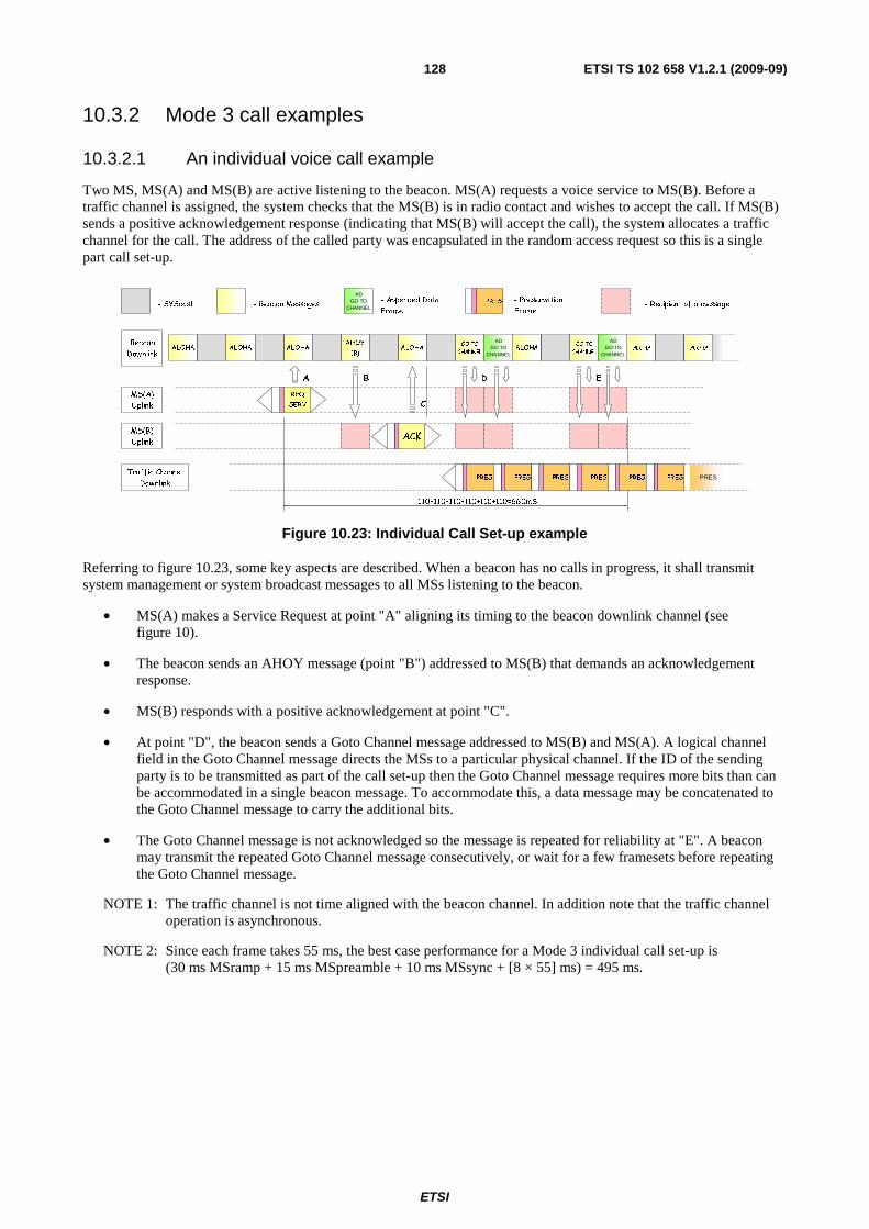
ETSI
ETSI TS 102 658 V1.2.1 (2009-09)128
10.3.2 Mode 3 call examples
10.3.2.1 An individual voice call example
Two MS, MS(A) and MS(B) are active listening to the beacon. MS(A) requests a voice service to MS(B). Before a traffic channel is assigned, the system checks that the MS(B) is in radio contact and wishes to accept the call. If MS(B) sends a positive acknowledgement response (indicating that MS(B) will accept the call), the system allocates a traffic channel for the call. The address of the called party was encapsulated in the random access request so this is a single part call set-up.
- Beacon Messages- SYScast - Recipient of a message
AD GO TO
CHANNEL- Appended Data
Frame
- Preservation
FramePRES
ALOHA
MS(A)
Uplink
MS(B)
Uplink
ALOHA ALOHAAHOY
(B)ALOHA
GO TO
CHANNEL
A B
C
D
Beacon
Downlink
110+110+110+110+110+110=660mS
AD GO TO
CHANNEL
E
ALOHAGO TO
CHANNEL
AD GO TO
CHANNELALOHAALOHA
REQ
SERV
ACK
PRESPRES PRES PRES PRES PRES PRES Traffic Channel
Downlink
Figure 10.23: Individual Call Set-up example
Referring to figure 10.23, some key aspects are described. When a beacon has no calls in progress, it shall transmit system management or system broadcast messages to all MSs listening to the beacon.
• MS(A) makes a Service Request at point "A" aligning its timing to the beacon downlink channel (see figure 10).
• The beacon sends an AHOY message (point "B") addressed to MS(B) that demands an acknowledgement response.
• MS(B) responds with a positive acknowledgement at point "C".
• At point "D", the beacon sends a Goto Channel message addressed to MS(B) and MS(A). A logical channel field in the Goto Channel message directs the MSs to a particular physical channel. If the ID of the sending party is to be transmitted as part of the call set-up then the Goto Channel message requires more bits than can be accommodated in a single beacon message. To accommodate this, a data message may be concatenated to the Goto Channel message to carry the additional bits.
• The Goto Channel message is not acknowledged so the message is repeated for reliability at "E". A beacon may transmit the repeated Goto Channel message consecutively, or wait for a few framesets before repeating the Goto Channel message.
NOTE 1: The traffic channel is not time aligned with the beacon channel. In addition note that the traffic channel operation is asynchronous.
NOTE 2: Since each frame takes 55 ms, the best case performance for a Mode 3 individual call set-up is (30 ms MSramp + 15 ms MSpreamble + 10 ms MSsync + [8 × 55] ms) = 495 ms.
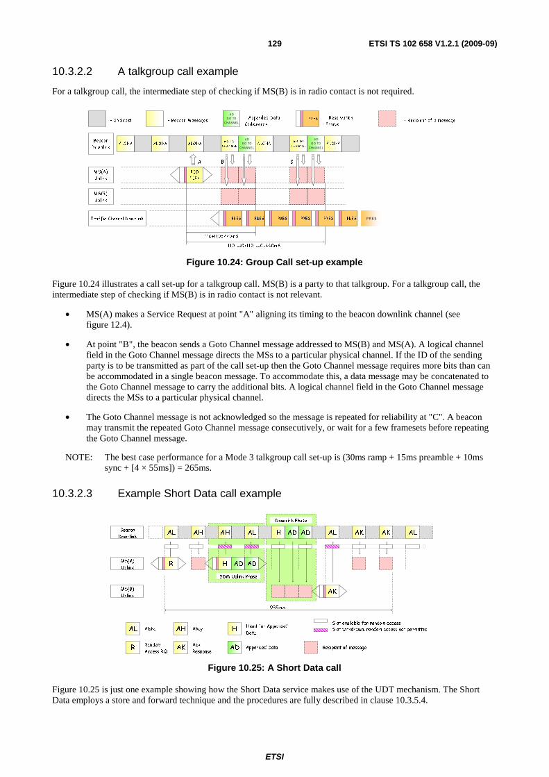
ETSI
ETSI TS 102 658 V1.2.1 (2009-09)129
10.3.2.2 A talkgroup call example
For a talkgroup call, the intermediate step of checking if MS(B) is in radio contact is not required.
110 +1 10 +110 +110 =4 4 0 m S
110 +1 10 =2 2 0 m S
C
A LO HA
M S(A)
U plin k
M S(B )
U plin k
A LO HA A LO HAG O T O
CH AN N EL
G O T O
C H A NN EL
A B
Beacon
D ow n lin k
T raff ic Channel D ow n link
A D G O TO
C HA NN E LA L O HA
A D G O TO
C HA N NE LA LO H A
R EQ
S E R V
P R E SPR ES PR E S PR E S PR E S PR E S PR E S
- Beacon M essages- SYScast - Rec ipien t o f a m essage
A D G O TO
C HA NN E L
- Appended D ata
Codew ords
- Reservatio n
F ram ePR ES
Figure 10.24: Group Call set-up example
Figure 10.24 illustrates a call set-up for a talkgroup call. MS(B) is a party to that talkgroup. For a talkgroup call, the intermediate step of checking if MS(B) is in radio contact is not relevant.
• MS(A) makes a Service Request at point "A" aligning its timing to the beacon downlink channel (see figure 12.4).
• At point "B", the beacon sends a Goto Channel message addressed to MS(B) and MS(A). A logical channel field in the Goto Channel message directs the MSs to a particular physical channel. If the ID of the sending party is to be transmitted as part of the call set-up then the Goto Channel message requires more bits than can be accommodated in a single beacon message. To accommodate this, a data message may be concatenated to the Goto Channel message to carry the additional bits. A logical channel field in the Goto Channel message directs the MSs to a particular physical channel.
• The Goto Channel message is not acknowledged so the message is repeated for reliability at "C". A beacon may transmit the repeated Goto Channel message consecutively, or wait for a few framesets before repeating the Goto Channel message.
NOTE: The best case performance for a Mode 3 talkgroup call set-up is (30ms ramp + 15ms preamble + 10ms sync + [4 × 55ms]) = 265ms.
10.3.2.3 Example Short Data call example
AL Slot withdrawn, random access not permittedAlohaSlot available for random access
AH Ahoy HHead for Appended
Data
Appended DataAKAck
ResponseADR
Random
Access RQRecipient of message
AL AH AL H AL AK AK AL
935mS
AD
SDM Uplink Phase
MS(A)
Uplink
MS(B)
Uplink
Beacon
Downlink
Downlink Phase
AD
R
AK
H AD AD
AH
Figure 10.25: A Short Data call
Figure 10.25 is just one example showing how the Short Data service makes use of the UDT mechanism. The Short Data employs a store and forward technique and the procedures are fully described in clause 10.3.5.4.
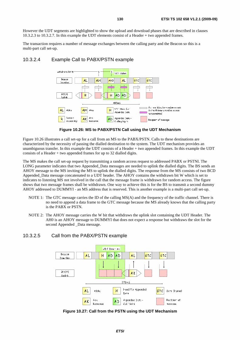
ETSI
ETSI TS 102 658 V1.2.1 (2009-09)130
However the UDT segments are highlighted to show the upload and download phases that are described in clauses 10.3.2.3 to 10.3.2.7. In this example the UDT elements consist of a Header + two appended frames.
The transaction requires a number of message exchanges between the calling party and the Beacon so this is a multi-part call set-up.
10.3.2.4 Example Call to PABX/PSTN example
AL Slot withdrawn, random access
not permitted
AlohaSlot available for random access
AH Ahoy HUDT Head for
Appended Data
Appended Data -
Dialling DigitsAK
Ack
ResponseADR
Random
Access RQRecipient of message
495mS
withdrawn bit W 11UDT Uplink
MS(A)
Uplink
Beacon
DownlinkAL AH AH0 AL GTC GTC
H AD ADR
Figure 10.26: MS to PABX/PSTN Call using the UDT Mechanism
Figure 10.26 illustrates a call set-up for a call from an MS to the PABX/PSTN. Calls to these destinations are characterized by the necessity of passing the dialled destination to the system. The UDT mechanism provides an unambiguous transfer. In this example the UDT consists of a Header + two appended frames. In this example the UDT consists of a Header + two appended frames for up to 32 dialled digits.
The MS makes the call set-up request by transmitting a random access request to addressed PABX or PSTNI. The LONG parameter indicates that two Appended_Data messages are needed to uplink the dialled digits. The BS sends an AHOY message to the MS inviting the MS to uplink the dialled digits. The response from the MS consists of two BCD Appended_Data message concatenated to a UDT header. The AHOY contains the withdrawn bit W which is set to indicates to listening MS not involved in the call that the message frame is withdrawn for random access. The figure shows that two message frames shall be withdrawn. One way to achieve this is for the BS to transmit a second dummy AHOY addressed to DUMMYI - an MS address that is reserved. This is another example is a multi-part call set-up.
NOTE 1: The GTC message carries the ID of the calling MS(A) and the frequency of the traffic channel. There is no need to append a data frame to the GTC message because the MS already knows that the calling party is the PABX or PSTN.
NOTE 2: The AHOY message carries the W bit that withdraws the uplink slot containing the UDT Header. The AH0 is an AHOY message to DUMMYI that does not expect a response but withdraws the slot for the second Appended _Data message.
10.3.2.5 Call from the PABX/PSTN example
A L Aloha HH ead f or Appended
D ata
Appended D ata -
CLI D ig itsAK
Ack
R esponseAD
R ec ip ient of
m essage
GTC G oto Channel
U D T D ow n link
A L AL GTC GTCH AD
2 7 0 m S
M S (A)
U plink
Beacon
D ow n linkAD
AK
Figure 10.27: Call from the PSTN using the UDT Mechanism
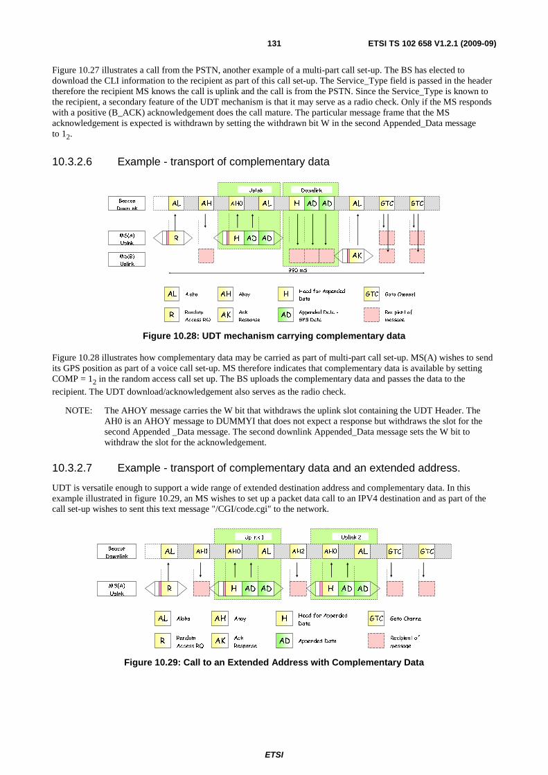
ETSI
ETSI TS 102 658 V1.2.1 (2009-09)131
Figure 10.27 illustrates a call from the PSTN, another example of a multi-part call set-up. The BS has elected to download the CLI information to the recipient as part of this call set-up. The Service_Type field is passed in the header therefore the recipient MS knows the call is uplink and the call is from the PSTN. Since the Service_Type is known to the recipient, a secondary feature of the UDT mechanism is that it may serve as a radio check. Only if the MS responds with a positive (B_ACK) acknowledgement does the call mature. The particular message frame that the MS acknowledgement is expected is withdrawn by setting the withdrawn bit W in the second Appended_Data message to 12.
10.3.2.6 Example - transport of complementary data
AL Aloha AH Ahoy HHead for Appended
Data
Appended Data -
GPS DataAK
Ack
ResponseADR
Random
Access RQ
Recipient of
message
GTC Goto Channel
Uplink
990 mS
Downlink
AL AH ALAH0 AL GTC GTCH AD
MS(A)
Uplnk
MS(B)
Uplink
Beacon
DownlinkAD
AK
R H AD AD
Figure 10.28: UDT mechanism carrying complementary data
Figure 10.28 illustrates how complementary data may be carried as part of multi-part call set-up. MS(A) wishes to send its GPS position as part of a voice call set-up. MS therefore indicates that complementary data is available by setting COMP = 12 in the random access call set up. The BS uploads the complementary data and passes the data to the
recipient. The UDT download/acknowledgement also serves as the radio check.
NOTE: The AHOY message carries the W bit that withdraws the uplink slot containing the UDT Header. The AH0 is an AHOY message to DUMMYI that does not expect a response but withdraws the slot for the second Appended _Data message. The second downlink Appended_Data message sets the W bit to withdraw the slot for the acknowledgement.
10.3.2.7 Example - transport of complementary data and an extended address.
UDT is versatile enough to support a wide range of extended destination address and complementary data. In this example illustrated in figure 10.29, an MS wishes to set up a packet data call to an IPV4 destination and as part of the call set-up wishes to sent this text message "/CGI/code.cgi" to the network.
AL Aloha AH Ahoy HHead for Appended
Data
Appended Data AKAck
ResponseADR
Random
Access RQ
Recipient of
message
GTC Goto Channel
Uplink 1
AL AH1 ALAH0 GTC GTC
MS(A)
Uplnk
Beacon
Downlink
R H AD AD
Uplink 2
AH2 ALAH0
H AD AD
Figure 10.29: Call to an Extended Address with Complementary Data
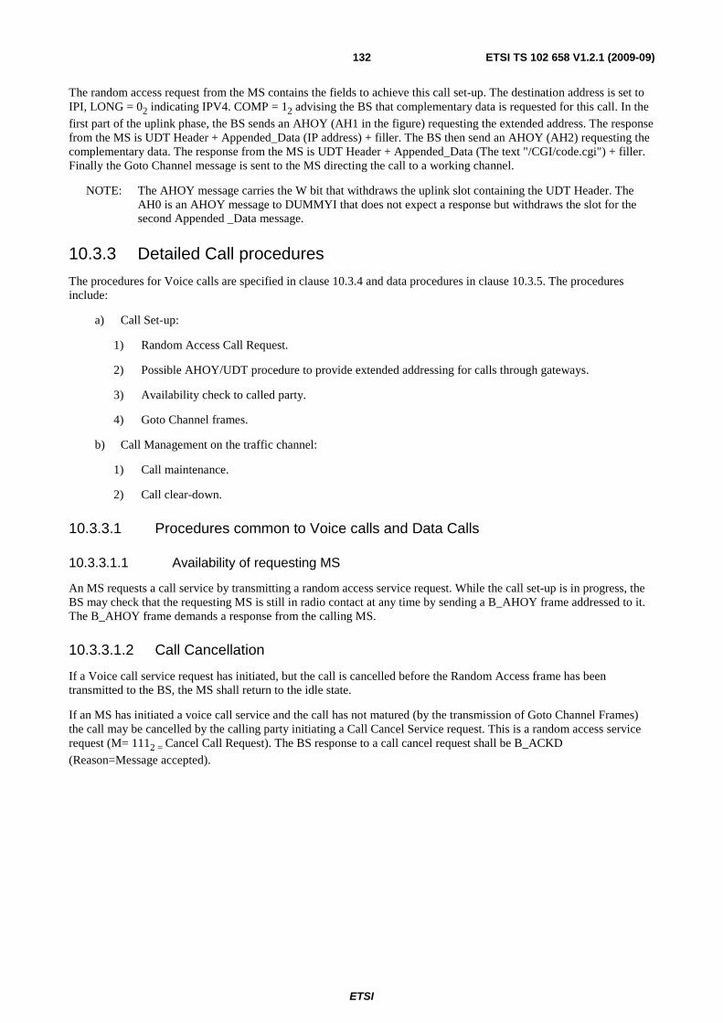
ETSI
ETSI TS 102 658 V1.2.1 (2009-09)132
The random access request from the MS contains the fields to achieve this call set-up. The destination address is set to IPI, LONG = 02 indicating IPV4. COMP = 12 advising the BS that complementary data is requested for this call. In the
first part of the uplink phase, the BS sends an AHOY (AH1 in the figure) requesting the extended address. The response from the MS is UDT Header + Appended_Data (IP address) + filler. The BS then send an AHOY (AH2) requesting the complementary data. The response from the MS is UDT Header + Appended_Data (The text "/CGI/code.cgi") + filler. Finally the Goto Channel message is sent to the MS directing the call to a working channel.
NOTE: The AHOY message carries the W bit that withdraws the uplink slot containing the UDT Header. The AH0 is an AHOY message to DUMMYI that does not expect a response but withdraws the slot for the second Appended _Data message.
10.3.3 Detailed Call procedures
The procedures for Voice calls are specified in clause 10.3.4 and data procedures in clause 10.3.5. The procedures include:
a) Call Set-up:
1) Random Access Call Request.
2) Possible AHOY/UDT procedure to provide extended addressing for calls through gateways.
3) Availability check to called party.
4) Goto Channel frames.
b) Call Management on the traffic channel:
1) Call maintenance.
2) Call clear-down.
10.3.3.1 Procedures common to Voice calls and Data Calls
10.3.3.1.1 Availability of requesting MS
An MS requests a call service by transmitting a random access service request. While the call set-up is in progress, the BS may check that the requesting MS is still in radio contact at any time by sending a B_AHOY frame addressed to it. The B_AHOY frame demands a response from the calling MS.
10.3.3.1.2 Call Cancellation
If a Voice call service request has initiated, but the call is cancelled before the Random Access frame has been transmitted to the BS, the MS shall return to the idle state.
If an MS has initiated a voice call service and the call has not matured (by the transmission of Goto Channel Frames) the call may be cancelled by the calling party initiating a Call Cancel Service request. This is a random access service request (M= 1112 = Cancel Call Request). The BS response to a call cancel request shall be B_ACKD
(Reason=Message accepted).
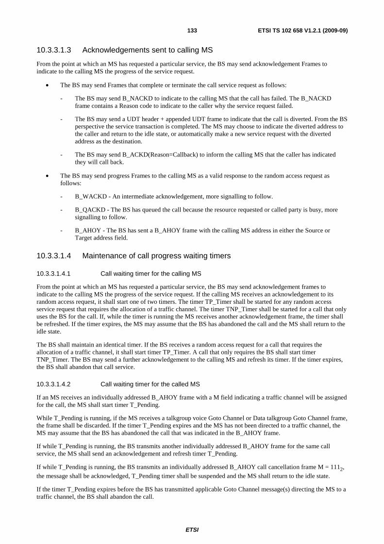
ETSI
ETSI TS 102 658 V1.2.1 (2009-09)133
10.3.3.1.3 Acknowledgements sent to calling MS
From the point at which an MS has requested a particular service, the BS may send acknowledgement Frames to indicate to the calling MS the progress of the service request.
• The BS may send Frames that complete or terminate the call service request as follows:
- The BS may send B_NACKD to indicate to the calling MS that the call has failed. The B_NACKD frame contains a Reason code to indicate to the caller why the service request failed.
- The BS may send a UDT header + appended UDT frame to indicate that the call is diverted. From the BS perspective the service transaction is completed. The MS may choose to indicate the diverted address to the caller and return to the idle state, or automatically make a new service request with the diverted address as the destination.
- The BS may send B_ACKD(Reason=Callback) to inform the calling MS that the caller has indicated they will call back.
• The BS may send progress Frames to the calling MS as a valid response to the random access request as follows:
- B_WACKD - An intermediate acknowledgement, more signalling to follow.
- B_QACKD - The BS has queued the call because the resource requested or called party is busy, more signalling to follow.
- B_AHOY - The BS has sent a B_AHOY frame with the calling MS address in either the Source or Target address field.
10.3.3.1.4 Maintenance of call progress waiting timers
10.3.3.1.4.1 Call waiting timer for the calling MS
From the point at which an MS has requested a particular service, the BS may send acknowledgement frames to indicate to the calling MS the progress of the service request. If the calling MS receives an acknowledgement to its random access request, it shall start one of two timers. The timer TP_Timer shall be started for any random access service request that requires the allocation of a traffic channel. The timer TNP_Timer shall be started for a call that only uses the BS for the call. If, while the timer is running the MS receives another acknowledgement frame, the timer shall be refreshed. If the timer expires, the MS may assume that the BS has abandoned the call and the MS shall return to the idle state.
The BS shall maintain an identical timer. If the BS receives a random access request for a call that requires the allocation of a traffic channel, it shall start timer TP_Timer. A call that only requires the BS shall start timer TNP_Timer. The BS may send a further acknowledgement to the calling MS and refresh its timer. If the timer expires, the BS shall abandon that call service.
10.3.3.1.4.2 Call waiting timer for the called MS
If an MS receives an individually addressed B_AHOY frame with a M field indicating a traffic channel will be assigned for the call, the MS shall start timer T_Pending.
While T_Pending is running, if the MS receives a talkgroup voice Goto Channel or Data talkgroup Goto Channel frame, the frame shall be discarded. If the timer T_Pending expires and the MS has not been directed to a traffic channel, the MS may assume that the BS has abandoned the call that was indicated in the B_AHOY frame.
If while T_Pending is running, the BS transmits another individually addressed B_AHOY frame for the same call service, the MS shall send an acknowledgement and refresh timer T_Pending.
If while T_Pending is running, the BS transmits an individually addressed B_AHOY call cancellation frame M = 1112,
the message shall be acknowledged, T_Pending timer shall be suspended and the MS shall return to the idle state.
If the timer T_Pending expires before the BS has transmitted applicable Goto Channel message(s) directing the MS to a traffic channel, the BS shall abandon the call.
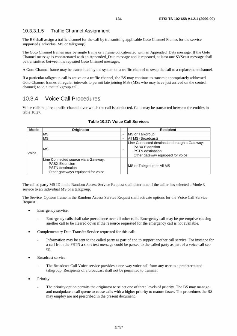
ETSI
ETSI TS 102 658 V1.2.1 (2009-09)134
10.3.3.1.5 Traffic Channel Assignment
The BS shall assign a traffic channel for the call by transmitting applicable Goto Channel Frames for the service supported (individual MS or talkgroup).
The Goto Channel frames may be single frame or a frame concatenated with an Appended_Data message. If the Goto Channel message is concatenated with an Appended_Data message and is repeated, at least one SYScast message shall be transmitted between the repeated Goto Channel messages.
A Goto Channel frame may be transmitted by the system on a traffic channel to swap the call to a replacement channel.
If a particular talkgroup call is active on a traffic channel, the BS may continue to transmit appropriately addressed Goto Channel frames at regular intervals to permit late joining MSs (MSs who may have just arrived on the control channel) to join that talkgroup call.
10.3.4 Voice Call Procedures
Voice calls require a traffic channel over which the call is conducted. Calls may be transacted between the entities in table 10.27.
Table 10.27: Voice Call Services
Mode Originator Recipient
Voice
MS - MS or Talkgroup MS - All MS (Broadcast)
MS -
Line Connected destination through a Gateway: PABX Extension PSTN destination Other gateway equipped for voice
Line Connected source via a Gateway: PABX Extension PSTN destination Other gateways equipped for voice
- MS or Talkgroup or All MS
The called party MS ID in the Random Access Service Request shall determine if the caller has selected a Mode 3 service to an individual MS or a talkgroup.
The Service_Options frame in the Random Access Service Request shall activate options for the Voice Call Service Request:
• Emergency service:
- Emergency calls shall take precedence over all other calls. Emergency call may be pre-emptive causing another call to be cleared down if the resource requested for the emergency call is not available.
• Complementary Data Transfer Service requested for this call:
- Information may be sent to the called party as part of and to support another call service. For instance for a call from the PSTN a short text message could be passed to the called party as part of a voice call set-up.
• Broadcast service:
- The Broadcast Call Voice service provides a one-way voice call from any user to a predetermined talkgroup. Recipients of a broadcast shall not be permitted to transmit.
• Priority:
- The priority option permits the originator to select one of three levels of priority. The BS may manage and manipulate a call queue to cause calls with a higher priority to mature faster. The procedures the BS may employ are not prescribed in the present document.
ETSI
ETSI TS 102 658 V1.2.1 (2009-09)135
10.3.4.1 Voice Call Procedures for the BS
An MS requests a Mode 3 voice service by generating a random access request frame with the Target Address set to one of the following:
• an individual MS address (single-part call set-up);
• a group MS address (single-part call set-up);
• a gateway address that indicates a multi-part call set-up.
When the BS responds to the random access request, it shall start a timer (TP_Timer). This timer shall be refreshed if the BS sends further call related Frames B_WACKD, B_QACKD or B_AHOY, to the calling party.
10.3.4.1.1 BS Response to single-part voice call set-up
When a random access voice service frame is received on the BS, the BS shall send a response in accordance with the random access procedures prescribed in clause 12.3.7.
The frames that represent a valid response to the voice call single-part service random access request are:
• An acknowledgement frame B_NACKD, B_QACKD, B_WACKD, B_ACKD(reason=callback).
• A UDT Head + appended frame(s) (voice call is diverted) UDT Header Frames ID = DIVERTI (conveying a diverted address) COMP = 02.
• A B_AHOY frame (called party radio check) if the call is to an individual MS address.
• A Goto Channel frame(s) for this call.
10.3.4.1.2 BS Response to multi-part voice call set-up
For calls to extended addresses, the MS requests multi-part addressing by generating a voice call random access request with the Destination Address field set to a gateway address (PABXI, PSTNI, etc) and the LONG field to indicate if the number of Appended_Data messages are required to transport the extended address from the MS. For calls to the PABX/PSTN one appended UDT can carry up to 16 dialled digits (LONG = 02), and for the number of dialled
digits = 17 to 32 (LONG = 12).
The Frames that shall represent a valid response to the voice call multi-part part voice service random access request are:
• An acknowledgement frame B_NACKD, B_WACKD(reason=Wait), B_QACKD.
• A B_AHOY frame for the calling MS to send the extended address information.
• A B_AHOY frame for the calling MS to send complementary data (see clause 4.5).
For b) The BS shall then invoke the UDT procedure by sending a B_AHOY to the calling MS to send the extended address information. For a call to the PABX or PSTN the extended address information shall be BCD digits. The LONG field in the B-AHOY frame shall be copied from the LONG field received from the MS B_RAND frame. If the BS does not successfully receive the UDT from the MS, the BS may repeat the B_AHOY, or transmit a B_NACKD to indicate failure of the call.
For c) The BS shall then invoke the UDT procedure by sending a B_AHOY to the calling MS to send the complementary data. The format of the complementary data is specified in the UDT. If the BS does not successfully receive the UDT from the MS, the BS may repeat the B_AHOY, or transmit a B_NACKD to indicate failure of the call, or continue with the call set-up and abandon the complementary data.

ETSI
ETSI TS 102 658 V1.2.1 (2009-09)136
10.3.4.1.3 Acknowledgements sent on the BS to the calling MS (voice)
The BS may send acknowledgement Frames following the random access voice service request to indicate the progress of the call, to terminate the call or indicate call-back. If the BS sends a frame to indicate the progress of a call it shall start a waiting timer TP_Timer. (The calling party MS maintains a similar timer):
• Progress Frames are:
- B_WACKD: Intermediate acknowledgement. More Frames to follow;
- B_QACKD: Called MS engaged in another call;
- B_QACKD: Call is queued because the resource is in use at the moment.
• Termination Frames are selected from an appropriate Reason field in a B_NACKD frame (see clause 5.5.25).
- B_NACKD.
• Call-Back Frames indicate to the calling MS that the voice call service has been accepted by the called party for call back.
- B_ACKD(reason=CallBack).
• If the TS has previously accepted a call diversion indicating that this type of service request should be directed to another called party, the BS shall invoke the UDT and send a UDT Head + Appended_Data to the calling party. UDT Header Frames Source Address=DIVERTI (conveying a diverted address) COMP = 02.
10.3.4.1.4 Voice Radio Check
For calls to individual MS, the BS shall check that the called party is in radio contact and shall accept the call before a traffic channel is allocated.
The BS may check availability of the called party by:
• Sending a B_AHOY frame to that called party.
• Sending a UDT header with complementary data (if the complementary data service is active for this call).
If a response is not received from the called party the BS may repeat the B_AHOY.
The availability check demands a response from the called party:
• If the response is B_NACKU, the BS shall send an appropriate call failed response to the calling MS and echo the Reason in the B_NACKU frame.
• If the response is B_ACKU(Reason=CallBack), the BS shall send an appropriate CallBack response to the calling MS.
• If the response is B_ACKU(Reason=Message_Accepted), the BS shall progress the service request and allocate a traffic channel by transmitting appropriate Goto Channel frames.
10.3.4.1.5 Availability Check for Voice Calls connected through Gateways
For calls connected through gateways the BS equipment may wait until the destination is ready before allocating the traffic channel. For example a BS may wait until the PSTN handset has been answered before sending Goto Channel frames.
10.3.4.2 Voice Call Procedures for MS
An MS is able to request a voice call service to another individual MS or a talkgroup using a single-part service request. For a voice service requested to extended addresses through a gateway the MS requests a multi-part service request. For multi-part service requests the MS sets the gateway address as the called party. The full destination address is then uploaded from the MS to the BS by the UDT procedure.

ETSI
ETSI TS 102 658 V1.2.1 (2009-09)137
An MS requests a voice service by sending a B_RAND random access request complying with the random access procedures in clause 12.3.7. The fields in the random access request are set appropriately as prescribed in table 10.28.
Table 10.28: B_RAND fields for a Voice Call Service
Alias Alias Alias Value Length Meaning MT 11002 4 Message Type = B_RAND (BS uplink)
PARMS
ID0 + 1 24 Called MS, talkgroup, or gateway ID2 + 3 24 Calling MS ID
M
0002
3
Service requested is a Voice Call 0012 Service requested is a Voice Call + slow data 1012 Service requested is Voice + Appended_Data 1112 Cancel the call service
V 002 2 TCH is standard (non zero for custom) F 102 2 Comms Format = BS Uplink
EP 02
1 Non emergency service
12 Emergency Service PM N/A 1 Not Applicable for this particular message
MI
MI_TYPE 0002 3 N/A for a voice call service
MI_DET
002 2 UAD1 Appended Short Data. Number of appended UDTs required to transport the short data
2 UAD2
Appended Complementary Data. Number of appended UDTs required to transport the complementary data
02 1 LONG
PABX/PSTN dialled string is 1 to 16 digits. or IPV4
1 PABX/PSTN dialled string is 17 to 32 digits. or IPV6
02 1 COMP
Complementary Data service not required for this call
12 Complementary Data service is required for this call
02 1 PRIORITY
Normal Priority call
12 High Priority Call
02 1 BRCST
Non Broadcast Service
12 Broadcast Option
10.3.4.2.1 Initiating a single-part voice call service
For a voice service request to an individual MS or talkgroup, the destination address is completely expressed by the Called MS Address field in the random access frame. The M field specifies the voice call options when a traffic channel is allocated.
10.3.4.2.2 Response to the single-part individual voice service request
MS shall accept the following Frames as valid response to the single-part voice service request:
• an acknowledgement B_WACKD, B_QACKD, B_NACKD, B_ACKD(reason=callback);
• for an individual call service request, a B_AHOY called party radio check;
• a UDT header + appended UDT frame. UDT Header Source_Address=DIVERTI (conveying a diverted address) COMP = 02;
• a Goto Channel frame;
• if COMP = 12 a B_AHOY to upload the complementary data from the calling MS.

ETSI
ETSI TS 102 658 V1.2.1 (2009-09)138
10.3.4.2.3 Response to the multi-part voice service request
MS shall accept the following Frames as valid response to the multi-part voice service request:
• an acknowledgement B_WACKD, B_QACKD, B_NACKD;
• a B_AHOY frame to upload the extended address:
- for a call to the PABX/PSTN a B_AHOY to upload the dialled digits;
- if the Service_Options SUPED_SV = 12 a B_AHOY to upload the complementary data from the calling MS.
For b), if the Voice Call Service Request requires extended address information and the calling MS has selected the Complementary Data in the Service_Options, the BS uploads the information in two steps. The order in which the information is uploaded is not prescribed because the B_AHOY specifically indicates which UDT uplink procedure has been invoked by setting appropriate unambiguous Gateway fields in the B_AHOY frame. The gateway fields for B_AHOY Frames to support voice services are prescribed in table 10.29.
Table 10.29: B_AHOY fields for multi-part voice call set-up
Action Gateway address
Remark
MS send PSTN digits PSTNI The calling party shall send BCD dialled digits MS sends PABX digits PABXI The calling party shall send BCD dialled digits MS sends complementary data COMPI The format of the data shall be determined by the calling party
10.3.4.2.4 Acknowledgements received by the calling MS (voice)
At some time after sending the voice service request random access frame the calling MS may receive an acknowledgement. On receiving the acknowledgement, the MS shall start or restart a waiting timer, TP_Timer. (The BS maintains a similar timer.)
The MS shall take the actions prescribed:
• Progress Frames for a single-part voice call Service Request are:
- B_WACKD: Intermediate acknowledgement. More Frames to follow. The MS shall start TP_Timer for further signalling and may indicate a possible delay to the calling MS.
- B_QACKD: Called MS engaged in another call. The MS shall start TP_Timer for further signalling.
- B_QACKD: Call is queued because the resource is in use at the moment. The MS shall start TP_Timer for further signalling and may indicate a possible delay to the calling MS.
NOTE: The MS may choose to differentiate between 1), 2) and 3) by providing the calling MS with a visual or audible indication for each of the conditions.
• Termination Frames are selected from an appropriate Reason field in a B_NACKD frame (see clause 5.5.25).
- B_NACKD: Call refused and terminated. The B_NACKD frame provides a versatile range of Reason codes to indicate to the calling party why the Service request was terminated. The calling party shall return to the idle state.
• Call-Back frame to indicate to the calling MS that the voice call service has been accepted by the called party for call back. Service concluded. The calling party shall return to the idle state:
- B_ACKD(reason=CallBack).
• If the BS has previously accepted a call diversion indicating that this type of service request be directed to another called party, a UDT Head + Appended_Data indicating the diverted address.
ETSI
ETSI TS 102 658 V1.2.1 (2009-09)139
10.3.4.2.5 Availability Check to the called MS (voice)
For an individual MS address call set-up, the called MS shall receive a radio check to which it shall respond with an appropriate acknowledgement:
• The called party shall respond B_NACKU, if it cannot accept the call (the BS shall send an appropriate call failed response to the calling MS).
• The called party shall respond B_ACKU(Reason=CallBack), if the called MS wishes to return the call at some future time (the BS shall send an appropriate CallBack response to the calling MS).
• The calling party shall respond B_ACKU(Reason=Message_Accepted), if the call is accepted (the BS shall progress the service request and allocate a traffic channel by transmitting appropriate Goto Channel Frames).
10.3.4.2.6 Traffic Channel Allocation
MS shall check the address fields received in Goto Channel frames. If it is determined that the Goto Channel frame is applicable then it shall retune to the indicated traffic channel to commence the Voice Service.
• For Private Voice Goto Channel frame:
1) If an MS receives an individual Goto Channel frame where either the Source Address or the Target Address field matches its individual address then that frame is applicable.
• Group Voice Goto Channel frame:
1) If an MS receives a talkgroup Goto Channel frame with the Target Address field matching one of its talkgroup addresses then that frame is applicable.
2) If an MS receives a talkgroup Goto Channel frame with the Source Address matching its individual address then that frame is applicable.
3) If an MS receives a Broadcast Goto Channel frame with the Target Address matching one of its talkgroup addresses then that frame is applicable.
4) If an MS receives a Broadcast Goto Channel frame with the Source Address matching its individual address then that frame is applicable.
10.3.4.3 Procedures for the Voice Traffic Channel
MSs are directed to a voice traffic channel by an applicable Goto Channel frame transmitted on the beacon channel. When the voice call is terminated, MS returns to the beacon channel and the traffic channel is returned to idle for reassignment to another call.
A voice call may extend over several MS PTT items for the duration of the call (unless the call is terminated prematurely by the expiry of the voice traffic channel timer).
10.3.4.3.1 BS Procedures for the Voice Traffic Channel
A traffic channel shall carry one voice call at any one time. When the traffic channel is assigned for a call, the voice channel traffic timer shall be initialized as follows:
• For an individual MS/MS or MS/talkgroup normal or high priority call T_MS-MS_TMR.
• For a gateway individual MS or talkgroup normal or high priority call T_MS-LINE_TMR.
• For an emergency call T_EMERG_TMR.
10.3.4.3.1.1 Traffic Channel MS radio check
The BS may poll an individual MS on the traffic channel to check if the MS is active on the traffic channel by transmitting a Connection_Request header. This is identical to the Mode 2 called party check described in clause 10.2.1.
The response is T_ACK.

ETSI
ETSI TS 102 658 V1.2.1 (2009-09)140
The BS may also poll a talkgroup to check if at least one member of the talkgroup is active on the traffic channel by transmitting the called party check to the talkgroup.
The response is ACK. If more than one MS makes a response to this frame, it is likely that the BS will be unable to decode it because of collisions. The purpose of this procedure is to determine if any talkgroups are active, therefore the BS may use the presence of the burst for the result of the talkgroup radio check.
10.3.4.3.1.2 Disabling/enabling a users PTT
The BS may at any time send a Guard message (Guard_Type=DIS_PTT) addressed to an individual MS, talkgroup, or All Unit ID to disable the PTT. Since the T_PROTECT frame is unacknowledged the frame may be repeated at layer 2.
The BS may also at any time send a Guard message (Guard_Type=EN_PTT) addressed to an individual MS, talkgroup, or All Unit ID to enable the PTT. Since the Guard message is unacknowledged the frame may be repeated.
10.3.4.3.1.3 Swapping the call to a replacement voice traffic channel
The BS may send Goto Channel Frames on the traffic channel to move MS already active to an alternative voice traffic channel. If MS had previously received a Guard(Guard_Type=DIS_PTT to disable their PTT, the PTT shall be re-enabled on the replacement voice traffic channel unless the call service was a broadcast when called party(s) shall retain their PTT status (enable/disable) from the original call.
10.3.4.3.1.4 Removing MS from the traffic channel that are not legitimate parties
The BS may transmit Guard(Illegally_Parked) messages at any time. An MS whose address does not match either of the address fields in the Guard(Illegally_Parked) messages shall leave the traffic channel without making any further transmissions.
10.3.4.3.1.5 Clearing down the voice call
The BS shall clear the parties involved in the traffic voice call if:
• The relevant overall traffic call timer T_MS-MS_TMR, T_MS-LINE_TMR or T_EMERG_TMR expires.
• The BS receives a Disconnect_Request header + END frame with ID2 + 3 = ALLI.
• The BS detects by any other means that the call has ended (e.g. PSTN destination on hook).
• The TV_Hangtime interval timer expires.
The BS shall clear down the call by transmitting Disconnect_Request header + END frame(s). Since this frame is not acknowledged it may be repeated
10.3.4.3.1.6 Clearing down a particular MS or talkgroup
The BS may selectively clear an individual MS by transmitting a Disconnect_Request header with ID2 + 3 addressed to the particular MS ID to be cleared down.
A Disconnect_Request header with ID2 + 3 addressed to the particular MS ID to be cleared down.
The BS may clear a talkgroup by transmitting a Disconnect_Request header with ID2 + 3 addressed to the talkgroup to be cleared down.
10.3.4.3.2 MS Procedures for the Voice Traffic Channel
10.3.4.3.2.1 MS receives an MS radio check
If an MS receives a Connection_Request header addressed to its individual address then it shall respond with ACK.
If an MS receives a Connection_Request header to the talkgroup address previously transmitted in the Goto Channel frame that directed this MS to the traffic channel then it shall respond with a ACK.
ETSI
ETSI TS 102 658 V1.2.1 (2009-09)141
10.3.4.3.2.2 Disabling/enabling a users PTT
If the MS receives a Guard(Guard_Type=DIS_PTT) addressed to its individual address, or to its talkgroup address previously transmitted in the Goto Channel frame directing the MS to the traffic channel, or All Unit ID, the MS shall disable its PTT.
If the MS receives a Guard(Guard_Type=EN_PTT) addressed to its individual address, or to its talkgroup address previously transmitted in the Goto Channel frame, or All Unit ID, the MS shall re-enable its PTT unless this MS was the recipient of a broadcast call.
10.3.4.3.2.3 MS receives a Goto Channel frame(s)
If an MS receives an applicable Goto Channel addressed to its individual address or to its talkgroup address previously transmitted in the Goto Channel frame directing the MS to the traffic channel, then the MS shall retune to the new traffic channel. If the PTT was disabled prior to receiving the Goto Channel frame, the PTT shall be re-enabled unless this MS was the recipient of a broadcast call set-up or a call to All-Unit ID.
10.3.4.3.2.4 End of call
The MS shall signify the end of the call by transmitting Disconnect_Request + END frames on the traffic channel. The MS shall send the Disconnect_Request header + END frames consecutively then return to the beacon channel acquisition procedures (it is suggested that the BS sampled is the BS that transferred the call to the traffic channel).
10.3.4.3.2.5 MS receives Disconnect_Request header + END frame to ALLI
If an MS receives a Disconnect_Request header + END frame directed to ALLI then it shall return to the beacon channel acquisition procedures (it is suggested that the BS sampled is the BS that transferred the call to the traffic channel).
10.3.4.3.2.6 MS receives an individually addressed Disconnect Request
If an MS receives a Disconnect_Request header + END frame directed to the individual MS ID then it shall return to the beacon channel acquisition procedures (it is suggested that the BS sampled is the BS that transferred the call to the traffic channel).
10.3.4.3.2.7 MS receives a Disconnect Request addressed to a talkgroup
If an MS receives a Disconnect_Request header + END frame directed to a the MS talkgroup then it shall return to the beacon channel acquisition procedures (it is suggested that the BS sampled is the BS that transferred the call to the traffic channel).
10.3.4.3.2.8 MS receives a Guard message(s)
If an MS receives a Guard(Illegally_Parked) message, and the source or target address in the Guard(Illegally_Parked) message does not match the source or target address from the Goto Channel frame that directed the MS to the traffic channel, the MS shall leave the traffic channel without making any further transmissions.
10.3.4.3.2.9 Time out on the Traffic Channel
An MS shall maintain a number of timers while active on a voice traffic channel.
• Inactivity timer:
- An MS shall measure the length of time the MS is unable to detect adequate signal quality. If the MS fails to detect adequate signal quality for a continuous time TV_Inactive, the MS shall assume that the call has ended and return to the beacon channel acquisition procedures without sending any call termination signalling (it is suggested that the BS sampled is the BS that transferred the call to the traffic channel).

ETSI
ETSI TS 102 658 V1.2.1 (2009-09)142
• Item Duration timer:
- An MS shall maintain a maximum item duration timer. If the MS reaches the maximum item duration TV_Item, the MS shall disable the PTT and wait until the user releases the PTT before re-enabling the PTT.
• An overall traffic call timer:
- If the overall voice traffic call timer T_MS-MS_TMR, T_MS-LINE_TMR or T_EMERG_TMR expires, the MS shall transmit a number (N_Maint) of P_MAINT frames consecutively then return to the beacon channel acquisition procedures (it is suggested that the BS sampled is the BS that transferred the call to the traffic channel).
10.3.5. Data Call Procedures
Data calls require a traffic channel over which the call is conducted. Calls may be transacted between the entities in table 10.30.
Table 10.30: Data Call Services
Mode Originator Recipient
Data
MS - MS or talkgroup MS - All MS (Broadcast)
MS - Line Connected destination through a Gateway: Data Gateway Other gateway equipped for data
Line Connected source via a Gateway: Data Gateway Other gateway equipped for data
- MS or talkgroup or All MS
10.3.5.1 Data Call Procedures for the BS
An MS requests a Mode 3 service by generating a random access request frame with the Target Address set to:
• An individual MS address (single-part call set-up).
• A talkgroup MS address (single-part call set-up).
• A gateway address that indicates a multi-part call set-up.
When the BS responds to the random access request, it shall start a timer (TP_Timer). This timer shall be refreshed if the BS sends further call progress frames to the calling party.
10.3.5.1.1 BS Response to single-part data call set-up
When a random access data frame is received by the beacon, the BS shall send a response in accordance with the random access procedures prescribed in clause 12.3.7.
The frames that represent a valid response to the data call single-part service random access request are:
• An acknowledgement frame B_NACKD, B_QACKD, B_WACKD.
• A UDT Head + Appended_Data(s) (data call is diverted) UDT Header Frames Source_Address=DIVERTI (conveying a diverted address) Complementary Flag = 12 and UDT_Response = 02.
• A B_AHOY frame (called party radio check).
• A B_AHOY frame to upload complementary data from calling MS.
• A Goto Channel frame(s) for this call.

ETSI
ETSI TS 102 658 V1.2.1 (2009-09)143
10.3.5.1.2 BS Response to multi-part data call set-up
For calls to extended addresses, the MS requests multi-part addressing by generating a voice call random access request with the Destination Address field set to a gateway address (PABXI, PSTNI, etc) and the LONG field to indicate if the number of Appended_Data messages are required to transport the extended address from the MS. For calls to the PABX/PSTN one appended UDT can carry up to 16 dialled digits (LONG = 02), and for the number of dialled
digits = 17 to 32 (LONG = 12). For calls to an IP destination one appended UDT can carry an IPV4 address
(LONG = 02), and for IPV6 (LONG = 12).
The frames that shall represent a valid response to the voice call multi-part part voice service random access request are:
• An acknowledgement frame B_NACKD, B_WACKD(reason=Wait).
• A B_AHOY frame for the calling MS to send the extended address information.
• A B_AHOY frame for the calling MS to send complementary data (see clause 4.5).
For b) The BS shall then invoke the UDT procedure by sending a B_AHOY to the calling MS to send the extended address information. For a call to the PABX or PSTN the extended address information shall be BCD digits. The LONG Flag field in the B_AHOY frame shall be copied from the LONG Flag field received from the MS B_RAND frame.
For c) The BS shall then invoke the UDT procedure by sending a B_AHOY to the calling MS to send the complementary data. The format of the complementary data is specified in the UDT.
If the BS does not successfully receive the UDT from the MS, the BS may repeat the B_AHOY or transmit a B_NACKD to indicate failure of the call.
10.3.5.1.3 Acknowledgements sent on the BS to the calling MS (data)
The BS may send acknowledgement Frames following the random access data service request to indicate the progress of the call, to terminate the call. If the BS sends a frame to indicate the progress of a call it shall start a waiting timer TP_Timer. (The calling party MS maintains a similar timer).
• Progress Frames are:
- B_WACKD: Intermediate acknowledgement. More frames to follow.
- B_QACKD: Called MS engaged in another call.
- B_QACKD: Call is queued because the resource is in use at the moment.
• Termination Frames are selected from an appropriate Reason field in a B_NACKD frame):
- B_NACKD.
• If the beacon has previously accepted a call diversion indicating that this type of service request be directed to another called party, the BS shall invoke the UDT and send a UDT Head + Appended_Data to the calling party.
10.3.5.1.4 Radio Check for Data
For calls to individual MS, the BS shall check that the called party is in radio contact and will accept the call before a traffic channel is allocated. The radio check may also indicate that the called party data terminal equipment is ready.
The BS may check availability of the called party by:
a) Sending a B_AHOY frame to that called party.
b) Sending a Multi-frame UDT with complementary data (if the complementary data service is active for this call).
If a response is not received from the calling party the BS may repeat the B_AHOY.
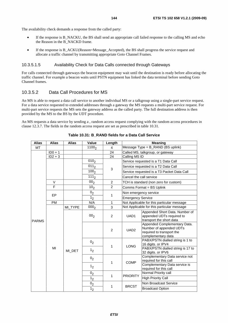
ETSI
ETSI TS 102 658 V1.2.1 (2009-09)144
The availability check demands a response from the called party:
• If the response is B_NACKU, the BS shall send an appropriate call failed response to the calling MS and echo the Reason in the B_NACKD frame.
• If the response is B_ACKU(Reason=Message_Accepted), the BS shall progress the service request and allocate a traffic channel by transmitting appropriate Goto Channel Frames.
10.3.5.1.5 Availability Check for Data Calls connected through Gateways
For calls connected through gateways the beacon equipment may wait until the destination is ready before allocating the traffic channel. For example a beacon waits until PSTN equipment has linked the data terminal before sending Goto Channel frames.
10.3.5.2 Data Call Procedures for MS
An MS is able to request a data call service to another individual MS or a talkgroup using a single-part service request. For a data service requested to extended addresses through a gateway the MS requests a multi-part service request. For multi-part service requests the MS sets the gateway address as the called party. The full destination address is then provided by the MS to the BS by the UDT procedure.
An MS requests a data service by sending a , random access request complying with the random access procedures in clause 12.3.7. The fields in the random access request are set as prescribed in table 10.31.
Table 10.31: B_RAND fields for a Data Call Service
Alias Alias Alias Value Length Meaning MT 11002 4 Message Type = B_RAND (BS uplink)
PARMS
ID0 + 1 24 Called MS, talkgroup, or gateway ID2 + 3 24 Calling MS ID
0102
3
Service requested is a T1 Data Call 0112 Service requested is a T2 Data Call 1002 Service requested is a T3 Packet Data Call 1112 Cancel the call service
V 002 2 TCH is standard (non zero for custom) F 102 2 Comms Format = BS Uplink
EP 02
1 Non emergency service
12 Emergency Service PM N/A 1 Not Applicable for this particular message
MI
MI_TYPE 0002 3 Not Applicable for this particular message
MI_DET
002 2 UAD1 Appended Short Data. Number of appended UDTs required to transport the short data
2 UAD2
Appended Complementary Data. Number of appended UDTs required to transport the complementary data
02 1 LONG
PABX/PSTN dialled string is 1 to 16 digits. or IPV4
12 PABX/PSTN dialled string is 17 to 32 digits. or IPV6
02 1 COMP
Complementary Data service not required for this call
12 Complementary Data service is required for this call
02 1 PRIORITY
Normal Priority call
12 High Priority Call
02 1 BRCST
Non Broadcast Service
12 Broadcast Option
ETSI
ETSI TS 102 658 V1.2.1 (2009-09)145
10.3.5.2.1 Initiating a single-part data call service
For a data service request to an individual MS or talkgroup, the destination address is completely expressed by the Target Address field in the random access frame. The Service_Type specifies if the data call service is addressed to an individual address or a talkgroup.
10.3.5.2.2 Response to the single-part data call service request
MS shall accept the following Frames as valid response to the single-part data service request:
a) an acknowledgement B_WACKD, B_QACKD, B_NACKD;
b) for an individual call service request, a B_AHOY called party radio check;
c) a Goto Channel frame;
d) if the COMP = 12 a B_AHOY to upload the complementary data from the calling MS;
e) a UDT Head + appended frames UDT Header Frames Source_Address=DIVERTI, COMP = 02.
10.3.5.2.3 Response to the multi-part data service request
MS shall accept the following Frames as valid response to the multi-part data service request:
f) an acknowledgement B_WACKD, B_QACKD, B_NACKD;
g) a B_AHOY frame to upload the extended address:
1) for a call to the PABX/PSTN a B_AHOY to upload the dialled digits;
2) if COMP = 12 a B_AHOY to upload the complementary data from the calling MS.
NOTE: For b), if the Data Call Service Request requires extended address information and the calling MS has selected the Complementary Data in the Service option, the BS uploads the information in two steps. The order in which the information is uploaded is not prescribed because the B_AHOY specifically indicates which UDT uplink procedure has been invoked by setting appropriate unambiguous fields in the B_AHOY frame.
10.3.5.2.4 Acknowledgements received by the calling MS (data)
At some time after sending the data service request random access frame the calling MS may receive an acknowledgement. On receiving the acknowledgement, the MS shall start or restart a waiting timer, TP_Timer. (The BS maintains a similar timer).
The MS shall take the actions prescribed:
a) Progress Frames for a single-part data call Service Request are:
1) B_WACKD: Intermediate acknowledgement. More Frames to follow. The MS shall start TP_Timer for further signalling and may indicate a possible delay to the calling MS;
2) B_QACKD (Reason=1000 00012): Called MS engaged in another call. The MS shall start TP_Timer for further signalling and may indicate a possible delay to the calling MS;
3) B_QACKD (Reason=1000 00002): Call is queued because the resource is in use at the moment. The MS shall start TP_Timer for further signalling and may indicate a possible delay to the calling MS. The MS may choose to differentiate between 1), 2) and 3) by providing the calling MS with a particular indication for each of the conditions.
b) Termination Frames are selected from an appropriate Reason field in a B_NACKD frame:
1) B_NACKD: Call refused and terminated. The B_NACKD frame provides a versatile range of Reason codes to indicate to the calling party why the Service request was terminated. The calling party shall return to the idle state.
ETSI
ETSI TS 102 658 V1.2.1 (2009-09)146
10.3.5.2.5 Availability Check to the called MS (data)
For an individual MS address call set-up, the called MS shall receive a radio check to which it will respond with an appropriate acknowledgement.
• The called party shall respond B_NACKU, if it cannot accept the call or its data terminal equipment is not ready (the BS shall send an appropriate call failed response to the calling MS).
• The calling party shall respond B_ACKU (Reason=Message_Accepted), if the call is accepted (the BS shall progress the service request and allocate a traffic channel by transmitting appropriate Goto Channel frames).
10.3.5.2.6 Traffic Channel Allocation
MS shall check the address fields received in Data Goto Channel frames. If it is determined that the Goto Channel frame is applicable then it shall retune to the indicated physical traffic channel to commence the Data Service.
a) For an individual MS Data Goto Channel frame:
1) If an MS receives a Goto Channel frame where either the Source Address or the Target Address field matches its individual address then that frame is applicable.
b) Talkgroup Data Goto Channel frame:
1) If an MS receives a talkgroup Goto Channel frame with the Target Address field matching one of its talkgroup addresses then that frame is applicable.
2) If an MS receives a talkgroup Goto Channel frame with the Source Address matching its individual address then that frame is applicable.
10.3.5.3 Procedures for the Data Traffic Channel
MSs are directed to a Data traffic channel by the beacon. When the Data call is terminated by either the BS or MS, the MS shall return to the beacon. When a physical channel has been assigned, data Frames of arbitrary length are transferred over the dPMR Air Interface using the data procedures described in clause 10.2.3. A Data call may continue unless the call is terminated by a) the MS or b) the BS or c) terminated prematurely as a result of the expiry of an overall traffic channel call timer). In the Mode 3 environment however, additional call maintenance Frames may be transmitted by the BS.
10.3.5.3.1 BS Procedures for the Data Traffic Channel
If a new physical channel is allocated by an applicable Goto Channel frame, the MS shall start the Data traffic timer T_DATA_TMR for T1, T2 and T3 data.
10.3.5.3.1.1 MS radio check
The BS may poll an individual MS on the traffic channel to check if the MS is active on the traffic channel by transmitting a Connection_Request header + END. This is identical to the Mode 2 called party check described in clause 10.2.1.
The response is T_ACK.
The BS may also poll a talkgroup to check if at least one member of the talkgroup is active on the traffic channel by transmitting a Connection_Request + END to a talkgroup.
The response is T_ACK. If more than one MS makes a response to this frame, it is likely that the BS will be unable to decode it because of collisions. The purpose of this procedure is to determine if any talkgroups are active therefore the BS may use the presence of the burst for the result of the talkgroup radio check.
10.3.5.3.1.2 Disabling/enabling a users transmission
The BS may at any time send a Guard(Guard_Type=DIS_PTT) addressed to an individual MS, talkgroup, or All Unit ID to disable all MS transmissions for the remainder of the call. Since the Guard message is unacknowledged the message may be repeated.
ETSI
ETSI TS 102 658 V1.2.1 (2009-09)147
The BS may also at any time send a Guard(Guard_Type=EN_PTT) addressed to an individual MS, talkgroup, or All Unit ID to enable the users transmission. Since the Guard message is unacknowledged the frame may be repeated.
10.3.5.3.1.3 Swapping the call to a replacement Data Traffic Channel
The BS may send Goto Channel frames to move MS already active to an alternative data traffic channel. If MS had previously received a GUARD to disable its transmissions, the transmissions shall be re-enabled on the replacement data traffic channel.
10.3.5.3.1.4 Clearing down the Data Channel
The BS shall clear down the parties involved in all traffic channel calls if:
• the relevant overall traffic channel call timer T_DATA_TMR expires;
• the BS receives a Disconnect_Request Header + END frame;
• the BS detects by any other means that the call has ended;
• the TV_Hangtime interval timer expires.
The BS shall clear down the data call by transmitting Disconnect_Request header + END frame(s). Since this frame is not acknowledged it may be repeated.
10.3.5.3.1.5 Clearing down a particular MS or talkgroup
The BS is able to clear down the parties involved in a data call if:
• the BS receives a Disconnect_Request header + END frame;
• the BS detects by any other means that the data call has ended.
The BS response to an applicable Disconnect_Request header is T_ACK.
The BS may selectively clear an MS by transmitting a Disconnect_Request header addressed to the individual MD ID.
The permitted response is T_ACK.
10.3.5.3.2 MS Procedures for the Data Traffic Channel
10.3.5.3.2.1 MS receives an MS radio check
If an MS receives a Connection_Request header to its individual address, then it shall respond with a T_ACK.
If an MS receives a Connection_Request header to it's the talkgroup address previously transmitted in the Goto Channel frame that directed this MS to the traffic channel then it shall respond with a T_ACK.
10.3.5.3.2.2 Disabling/enabling a user transmission
If the MS receives a Guard(Guard_Type=DIS_PTT) addressed to its individual address, or to it is talkgroup address previously transmitted in the Goto Channel frame, or All Unit ID, the MS shall disable it is transmissions.
If the MS receives a Guard(Guard_Type=EN_PTT) addressed to its individual address, to it is talkgroup address previously transmitted in the Goto Channel frame, or All Unit ID, the MS shall re-enable it is transmissions.
10.3.5.3.2.3 MS receives a Goto Channel frame(s)
If an MS receives an applicable Goto Channel addressed to its individual address or to its talkgroup address previously transmitted in the Goto Channel frame, then it shall retune to the designated physical channel.

ETSI
ETSI TS 102 658 V1.2.1 (2009-09)148
10.3.5.3.2.4 End of call
The MS shall signify the end of the call by transmitting a number of Connection_Request header _ + END headers. The MS shall send the Connection_Request header +END frames consecutively then return to the beacon channel acquisition procedures (it is suggested that the BS initially sampled is the BS that transferred the call to the traffic channel).
10.3.5.3.2.5 MS receives P_CLEAR
If an MS receives a Disconnect_Request header + END frame then it shall abandon the traffic channel and enter control channel acquisition procedures.
10.3.5.3.2.6 MS receives a selective clear P_AHOY
If an MS receives an individually addressed Disconnect_Request Header + END frame then it shall send a T_ACK, abandon the traffic channel and return to the beacon channel acquisition procedures (it is suggested that the BS initially sampled is the BS that transferred the call to the traffic channel).
If an MS receives a Disconnect_Request Header + END addressed to its talkgroup address previously transmitted in the Goto Channel frame the talkgroup then it shall send a T_ACK abandon the traffic channel and return to the beacon channel acquisition procedures (it is suggested that the BS initially sampled is the BS that transferred the call to the traffic channel).
10.3.5.3.2.7 Time-out on the Traffic Channel
An MS shall maintain a number of timers while active on a data traffic channel.
a) Inactivity timer:
- An MS shall measure the length of time the MS is unable to detect adequate signal quality. If the MS fails to detect adequate signal quality for a continuous time TD_Inactive, the MS shall assume that the call has ended and return to the beacon channel acquisition procedures without sending any call termination signalling (it is suggested that the BS sampled is the BS that transferred the call to the traffic channel).
b) Item Duration timer:
- An MS shall maintain the maximum item duration timer TD_Item. If the MS reaches the maximum item duration TD_Item, the MS shall discontinue the item and indicate to the application layer that the item was not successfully transmitted.
c) An overall traffic channel call timer:
- If the overall data traffic channel call timer T_DATA_TMR expires, the MS shall transmit a Disconnect_Request Header + END frames then return to the beacon channel acquisition procedures (it is suggested that the BS sampled is the BS that transferred the call to the traffic channel) If the MS was sending data frames when the overall data traffic call timer expires, the MS shall indicate to the application layer prior to transmitting the Disconnect_Request Header + END frames.
10.3.5.4 Short Data Message Procedure
The Short Data Message service enables data to be transmitted between dPMR entities using the beacon channel. Up to 256 bits of data may be transported using this service in a number of formats including binary, BCD, 7 bit text, 8 bit characters, and NMEA (EN 61162-1 [1]).
The Short Data Message procedure uses the multi-part call set-up. An MS may send a Short Data Message to an MS, a talkgroup, the PSTN or PABX, a line connected gateway, a dispatcher gateway, or all MS (if the BS permits it). The BS may also transmit a short data message from a gateway addressed to an individual MS or talkgroup.
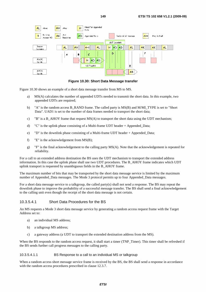
ETSI
ETSI TS 102 658 V1.2.1 (2009-09)149
AL Aloha AH Ahoy HHead for Appended
Data
Appended DataAKAck
ResponseR
Random
Access RQAD Recipient of message AH0 Ahoy to Null
AL AH H AL AK AK ALADAL
UDT Uplink
UDT Downlink
A B CD
E
F
MS(A)
Uplink
MS(B)
Uplink
Beacon
DownlinkAD
H AD AD
AK
AH0
Figure 10.30: Short Data Message transfer
Figure 10.30 shows an example of a short data message transfer from MS to MS.
a) MS(A) calculates the number of appended UDTs needed to transmit the short data. In this example, two appended UDTs are required;
b) "A" is the random access B_RAND frame. The called party is MS(B) and M/MI_TYPE is set to "Short Data". UAD1 is set to the number of data frames needed to transport the short data;
c) "B" is a B_AHOY frame that request MS(A) to transport the short data using the UDT mechanism;
d) "C" is the uplink phase consisting of a Multi-frame UDT header + Appended_Data;
e) "D" is the downlink phase consisting of a Multi-frame UDT header + Appended_Data;
f) "E" is the acknowledgement from MS(B);
g) "F" is the final acknowledgement to the calling party MS(A). Note that the acknowledgement is repeated for reliability.
For a call to an extended address destination the BS uses the UDT mechanism to transport the extended address information. In this case the uplink phase shall use two UDT procedures. The B_AHOY frame indicates which UDT uplink transport is requested by unambiguous fields in the B_AHOY frame.
The maximum number of bits that may be transported by the short data message service is limited by the maximum number of Appended_Data messages. The Mode 3 protocol permits up to four Appended_Data messages.
For a short data message service to a talkgroup, the called party(s) shall not send a response. The BS may repeat the downlink phase to improve the probability of a successful message transfer. The BS shall send a final acknowledgement to the calling unit even though the receipt of the short data message is not certain.
10.3.5.4.1 Short Data Procedures for the BS
An MS requests a Mode 3 short data message service by generating a random access request frame with the Target Address set to:
a) an individual MS address;
b) a talkgroup MS address;
c) a gateway address (a UDT to transport the extended destination address from the MS).
When the BS responds to the random access request, it shall start a timer (TNP_Timer). This timer shall be refreshed if the BS sends further call progress messages to the calling party.
10.3.5.4.1.1 BS Response to a call to an individual MS or talkgroup
When a random access short message service frame is received by the BS, the BS shall send a response in accordance with the random access procedures prescribed in clause 12.3.7.
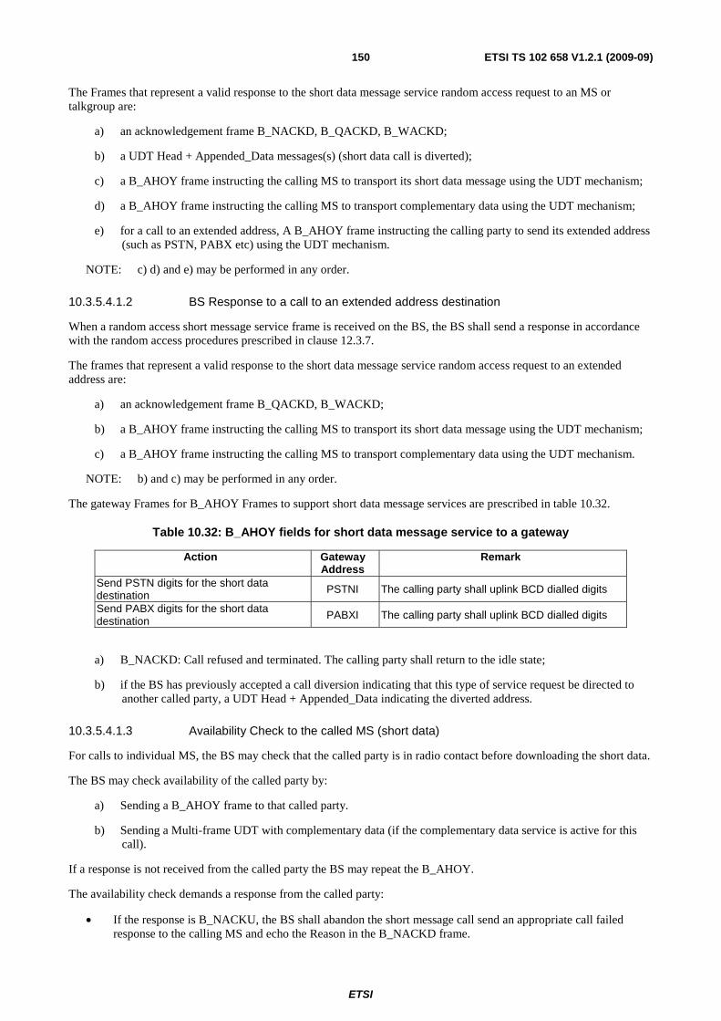
ETSI
ETSI TS 102 658 V1.2.1 (2009-09)150
The Frames that represent a valid response to the short data message service random access request to an MS or talkgroup are:
a) an acknowledgement frame B_NACKD, B_QACKD, B_WACKD;
b) a UDT Head + Appended_Data messages(s) (short data call is diverted);
c) a B_AHOY frame instructing the calling MS to transport its short data message using the UDT mechanism;
d) a B_AHOY frame instructing the calling MS to transport complementary data using the UDT mechanism;
e) for a call to an extended address, A B_AHOY frame instructing the calling party to send its extended address (such as PSTN, PABX etc) using the UDT mechanism.
NOTE: c) d) and e) may be performed in any order.
10.3.5.4.1.2 BS Response to a call to an extended address destination
When a random access short message service frame is received on the BS, the BS shall send a response in accordance with the random access procedures prescribed in clause 12.3.7.
The frames that represent a valid response to the short data message service random access request to an extended address are:
a) an acknowledgement frame B_QACKD, B_WACKD;
b) a B_AHOY frame instructing the calling MS to transport its short data message using the UDT mechanism;
c) a B_AHOY frame instructing the calling MS to transport complementary data using the UDT mechanism.
NOTE: b) and c) may be performed in any order.
The gateway Frames for B_AHOY Frames to support short data message services are prescribed in table 10.32.
Table 10.32: B_AHOY fields for short data message service to a gateway
Action Gateway Address
Remark
Send PSTN digits for the short data destination PSTNI The calling party shall uplink BCD dialled digits
Send PABX digits for the short data destination PABXI The calling party shall uplink BCD dialled digits
a) B_NACKD: Call refused and terminated. The calling party shall return to the idle state;
b) if the BS has previously accepted a call diversion indicating that this type of service request be directed to another called party, a UDT Head + Appended_Data indicating the diverted address.
10.3.5.4.1.3 Availability Check to the called MS (short data)
For calls to individual MS, the BS may check that the called party is in radio contact before downloading the short data.
The BS may check availability of the called party by:
a) Sending a B_AHOY frame to that called party.
b) Sending a Multi-frame UDT with complementary data (if the complementary data service is active for this call).
If a response is not received from the called party the BS may repeat the B_AHOY.
The availability check demands a response from the called party:
• If the response is B_NACKU, the BS shall abandon the short message call send an appropriate call failed response to the calling MS and echo the Reason in the B_NACKD frame.

ETSI
ETSI TS 102 658 V1.2.1 (2009-09)151
• If the response is B_ACKU (Reason=Message_Accepted), the BS shall progress the service request and download the short data message using the UDT mechanism.
10.3.5.4.1.4 Final acknowledgement to the calling party
In the downlink phase, the BS downloads the short data message to the called party. If the recipient is an individual MS an acknowledgement shall be received on the BS. For a short data message service to a talkgroup, the downlink phase may be repeated but no acknowledgement shall be expected.
The BS shall send an appropriate acknowledgement to the calling party to indicate the outcome of the short data transfer request.
10.3.5.4.2 Short Data Message procedures for MS
An MS requests a short data message call service to another individual MS or a talkgroup or gateway using a multi-part service request. For calls to an extended address the transport of the extended address and the short data message is uploaded by two separate UDT transfers.
An MS requests a short data service by sending a B_RAND random access request complying with the random access procedures in clause 12.3.7. The Fields in the random access request are passed from the application layers - set appropriately as prescribed in table 10.33.
Table 10.33: B_RAND fields for a Short Data Message Service
Alias Alias Alias Value Length Meaning MT 11002 4 Message Type = B_RAND (BS uplink)
PARMS
ID0 + 1 24 Called MS, talkgroup, or gateway ID2 + 3 24 Calling MS ID
1102
3 Service requested is defined by MI_TYPE
1112 Cancel the call service
V 002 2 TCH is standard (non zero for custom) F 102 2 Comms Format = BS Uplink
EP 02
1 Non emergency service
12 Emergency Service PM N/A 1 Not Applicable for this particular message
MI
MI_TYPE 0002 3 Service Requested is Short Data
MI_DET
2 UAD1 Appended Short Data. Number of appended UDTs required to transport the short data
2 UAD2
Appended Complementary Data. Number of appended UDTs required to transport the complementary data
02 1 LONG
PABX/PSTN dialled string is 1 to 16 digits. or IPV4
12 PABX/PSTN dialled string is 17 to 32 digits. or IPV6
02 1 COMP
Complementary Data service not required for this call
12 Complementary Data service is required for this call
02 1 PRIORITY
Normal Priority call
12 High Priority Call
02 1 BRCST
Non Broadcast Service
12 Broadcast Option

ETSI
ETSI TS 102 658 V1.2.1 (2009-09)152
10.3.5.4.3 Initiating a Short Data Message service
For a short data message service request to an individual MS or talkgroup, the destination address is completely expressed by the ID0 + 1 field in the B_RAND random access frame. For calls to a gateway addresses the Target_address or Gateway field in the B_RAND is set to the gateway address.
The MS shall attempt access until it receives a valid response, or the service is cancelled by the user, or the attempt fails by sending the maximum number of random access Frames or the random access timer expires.
10.3.5.4.4 Response to a random access short data message
The calling MS shall accept the following Frames a valid response to the SDM random access request:
a) an acknowledgement frame B_NACKD, B_QACKD, B_WACKD;
b) a UDT Head + appended data message(s) (short data call is diverted);
c) a B_AHOY frame instructing the calling MS to transport its short data message using the UDT mechanism;
d) a B_AHOY frame instructing the calling MS to transport complementary data using the UDT mechanism;
e) for a call to an extended address, A B_AHOY frame instructing the calling party to send its extended address using the UDT mechanism.
NOTE: c) d) and e) may be performed in any order.
10.3.5.4.5 Acknowledgements received by the calling MS
When the B_RAND frame has been transmitted by the calling party, an initial response may be received by the calling party as specified in clause 10.3.5.4.4.
At any time further Frames may be sent to the calling party as follows:
a) a B_NACKD at any time to indicate the call has failed. The Reason field shall be set to indicate the reason for the call failure;
b) a B_WACKD if more signalling will follow;
c) after the short data message has been successfully transported, B_ACKD frame.
If a B_NACKD is received, the calling MS shall abandon the short data message call and return to the idle state.
Any applicable call progress acknowledgements received shall restart the TNP_timer.
10.3.5.4.6 Timeout waiting for further signalling
An MS waiting for further signalling shall abandon the short data message service and return to the idle state if the TNP_Timer expires.
10.3.5.4.7 MS receiving a short data message
If an MS receives a multi frame UDT Head frame with the Target Address matching its individual address, it shall respond with an appropriate acknowledgement. The Appended_Data field in the UDT header indicates the number of appended UDT messages.
If an MS receives a multi UDT Header message with the Target Address matching a talkgroup, it shall accept the information contained in the Appended_Data message, but shall transmit no response.
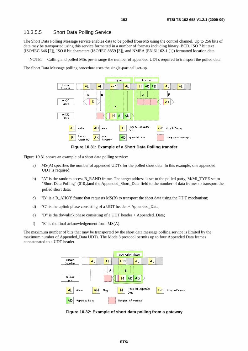
ETSI
ETSI TS 102 658 V1.2.1 (2009-09)153
10.3.5.5 Short Data Polling Service
The Short Data Polling Message service enables data to be polled from MS using the control channel. Up to 256 bits of data may be transported using this service formatted in a number of formats including binary, BCD, ISO 7 bit text (ISO/IEC 646 [2]), ISO 8 bit characters (ISO/IEC 8859 [3]), and NMEA (EN 61162-1 [1]) formatted location data.
NOTE: Calling and polled MSs pre-arrange the number of appended UDTs required to transport the polled data.
The Short Data Message polling procedure uses the single-part call set-up.
AL AH AL H AL ALAD
Uplink Downlink
A B
C
D E
MS(A)
Uplink
MS(B)
Uplink
Beacon
Downlink
R AK
H AD AD
ADAH0
AL Aloha AH Ahoy HHead for Appended
Data
Appended DataAKAck
ResponseADR
Random
Access RQRecipient of message
AH0 Ahoy to Dummy
Figure 10.31: Example of a Short Data Polling transfer
Figure 10.31 shows an example of a short data polling service:
a) MS(A) specifies the number of appended UDTs for the polled short data. In this example, one appended UDT is required;
b) "A" is the random access B_RAND frame. The target address is set to the polled party, M/MI_TYPE set to "Short Data Polling" (0102)and the Appended_Short_Data field to the number of data frames to transport the
polled short data;
c) "B" is a B_AHOY frame that requests MS(B) to transport the short data using the UDT mechanism;
d) "C" is the uplink phase consisting of a UDT header + Appended_Data;
e) "D" is the downlink phase consisting of a UDT header + Appended_Data;
f) "E" is the final acknowledgement from MS(A).
The maximum number of bits that may be transported by the short data message polling service is limited by the maximum number of Appended_Data UDTs. The Mode 3 protocol permits up to four Appended Data frames concatenated to a UDT header.
AL AH AH0 AL AL
UDT Uplink Phase
A B
MS(A)
Uplink
Beacon
Downlink
H AD AD
AL Aloha AH Ahoy HHead for Appended
Data
Appended DataAD Recipient of message
AH0 Ahoy to Dummy
Figure 10.32: Example of short data polling from a gateway
ETSI
ETSI TS 102 658 V1.2.1 (2009-09)154
Figure 10.32 shows a short data polling transfer from a gateway to an MS. The BS requests the short data by transmitting a B_AHOY frame addressed to MS(A). MS(A) responds with the UDT head + short data.
10.3.5.5.1 Short Data Polling Procedures for the BS
An MS requests a Mode 3 short data polling message service by generating a random access request frame with the Target Address set to an individual address.
When the BS responds to the random access request, it shall start a timer (TNP_Timer). This timer shall be refreshed if the BS sends further call progress frames to the calling party.
10.3.5.5.1.1 BS Response to a poll request from an MS
When a random access short data poll service frame is received on the BS, the BS shall send a response in accordance with the random access procedures prescribed in clause 12.3.7.
The Frames that represent a valid response to the short data polling service random access request to an MS or talkgroup are:
a) an acknowledgement frame B_NACKD, B_QACKD, B_WACKD;
b) a B_AHOY frame instructing the polled MS to transport complementary data using the UDT mechanism.
NOTE: If the polled MS has diverted its calls the response is B_NACKD (Reason= Div_Cause_Fail).
10.3.5.5.1.2 Availability Check to the called MS (short data poll)
The BS may check that the called party is in radio contact before polling the MS for the short data.
The BS may check availability of the polled party by sending a B_AHOY frame addressed to the polled MS individual address. If a response is not received from the calling party the BS may repeat the B_AHOY.
The availability check demands a response from the called party:
a) If the response is B_NACKU, the BS shall abandon the short message polling transaction, send an appropriate call failed response to the calling MS and echo the Reason in the B_NACKU frame.
b) If the response is B_ACKU (Reason=Message_Accepted), the BS shall progress the service request and poll the MS for the short data using the UDT mechanism.
10.3.5.5.1.3 Delivery of the polled data to the calling party
In the downlink phase, the BS downloads the short data polled message to the calling party using the UDT mechanism.
The calling MS shall send an appropriate acknowledgement to the BS to indicate the outcome of the short data polling request.
10.3.5.5.1.4 Final acknowledgement by the calling party to the BS
The final phase of the polling transaction is the acknowledgement from the calling MS that the polled data was successfully received. If the BS does not receive a response, it may repeat the downlink phase described in clause 10.3.5.5.1.3.
10.3.5.5.1.5 Short Data Polling procedures from a BS gateway
The short polling service initiated through a gateway is illustrated in figure 10.32. The BS transmits a B_AHOY frame addressed to an individual MS. The B_AHOY frame demands a response:
a) If the response is B_NACKU, the BS shall abandon the short message polling transaction.
b) If the response is a multi-frame UDT containing the polled data, the transaction is complete.
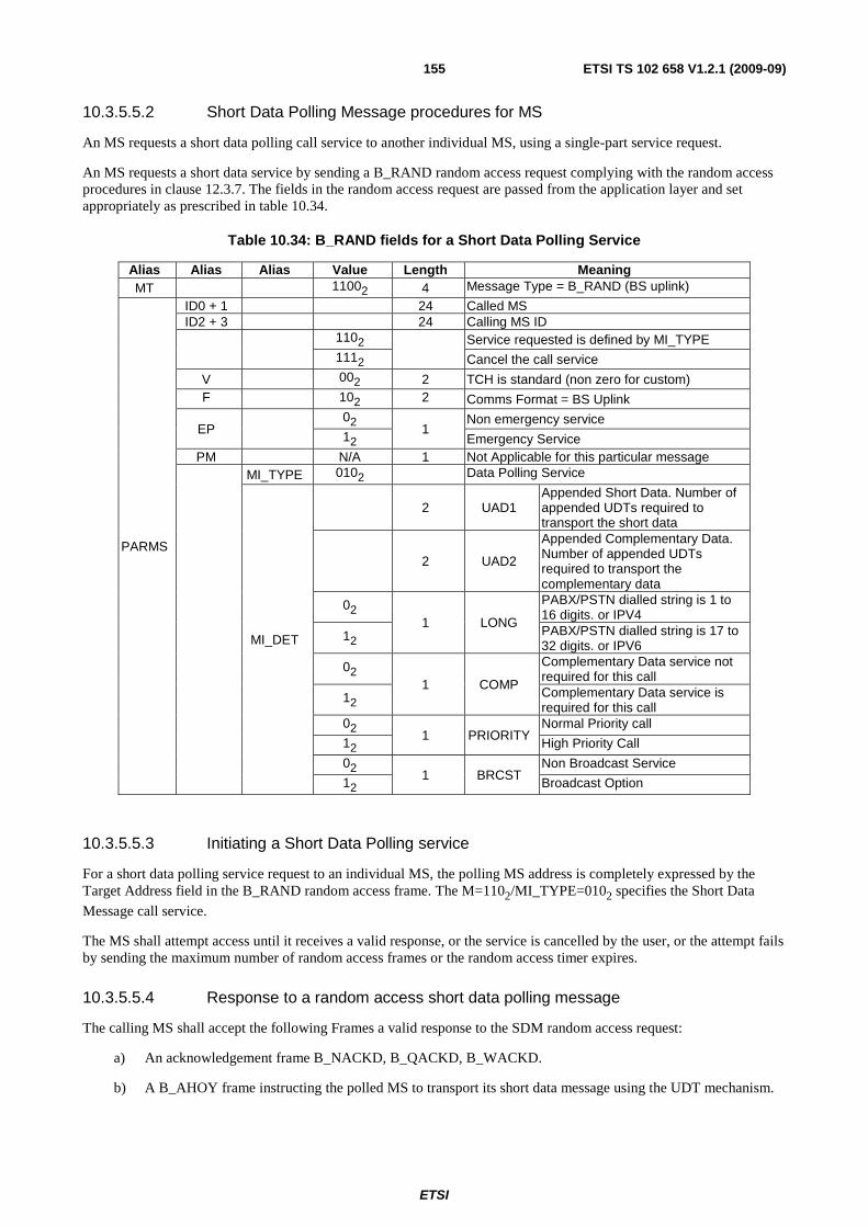
ETSI
ETSI TS 102 658 V1.2.1 (2009-09)155
10.3.5.5.2 Short Data Polling Message procedures for MS
An MS requests a short data polling call service to another individual MS, using a single-part service request.
An MS requests a short data service by sending a B_RAND random access request complying with the random access procedures in clause 12.3.7. The fields in the random access request are passed from the application layer and set appropriately as prescribed in table 10.34.
Table 10.34: B_RAND fields for a Short Data Polling Service
Alias Alias Alias Value Length Meaning MT 11002 4 Message Type = B_RAND (BS uplink)
PARMS
ID0 + 1 24 Called MS ID2 + 3 24 Calling MS ID
1102
Service requested is defined by MI_TYPE
1112 Cancel the call service
V 002 2 TCH is standard (non zero for custom) F 102 2 Comms Format = BS Uplink
EP 02
1 Non emergency service
12 Emergency Service PM N/A 1 Not Applicable for this particular message
MI_TYPE 0102 Data Polling Service
MI_DET
2 UAD1 Appended Short Data. Number of appended UDTs required to transport the short data
2 UAD2
Appended Complementary Data. Number of appended UDTs required to transport the complementary data
02 1 LONG
PABX/PSTN dialled string is 1 to 16 digits. or IPV4
12 PABX/PSTN dialled string is 17 to 32 digits. or IPV6
02 1 COMP
Complementary Data service not required for this call
12 Complementary Data service is required for this call
02 1 PRIORITY
Normal Priority call
12 High Priority Call
02 1 BRCST
Non Broadcast Service
12 Broadcast Option
10.3.5.5.3 Initiating a Short Data Polling service
For a short data polling service request to an individual MS, the polling MS address is completely expressed by the Target Address field in the B_RAND random access frame. The M=1102/MI_TYPE=0102 specifies the Short Data
Message call service.
The MS shall attempt access until it receives a valid response, or the service is cancelled by the user, or the attempt fails by sending the maximum number of random access frames or the random access timer expires.
10.3.5.5.4 Response to a random access short data polling message
The calling MS shall accept the following Frames a valid response to the SDM random access request:
a) An acknowledgement frame B_NACKD, B_QACKD, B_WACKD.
b) A B_AHOY frame instructing the polled MS to transport its short data message using the UDT mechanism.
ETSI
ETSI TS 102 658 V1.2.1 (2009-09)156
10.3.5.5.5 Final Acknowledgement transmitted by the calling MS
In the downlink phase, the BS downloads the short data polled message to the calling party. Valid responses to the BS are:
a) An acknowledgement frame B_NACKU indicating the transaction has failed.
b) An acknowledgement frame B_ACKU indicating the transaction was successful.
10.3.5.5.6 Timeout waiting for further signalling
An MS waiting for further signalling shall abandon the short data polling service and return to the idle state if the TNP_Timer expires.
10.3.5.5.7 MS receiving a B_AHOY poll for a short polling message
If an MS receives a B_AHOY frame with the Target Address matching its individual address and the Service_Type = Short Data Polling Service it shall respond with:
c) A UDT Header frame with the Target Address matching its calling party (source) address from the B_AHOY frame. The Appended_Frames field in the UDT header indicates the number of appended UDT frames.
d) A B_NACKU frame if the polled MS does not wish to accept the polling request.
10.3.5.6 Status Call Service
The Status Message service enables data to be transmitted between dPMR entities on the beacon channel. Seven bits of data may be transported using this service. The status delivery service transports a status message from the initiator to a recipient. The status polling service enables an initiator to request a status message from an addressed entity. Seven bits are transported representing 256 status messages. Each status message has a user-defined meaning.
Status messages addressed from MS to the beacon are system messages.
10.3.5.6.1 Status Service Delivery Procedure
The Status Message procedure employs a store and forward mechanism. An MS may send a Status Message to an individual MS, the PSTN or PABX, a line connected gateway, a dispatcher gateway or the BS. The BS may also transmit a short data message from a gateway or special ID addressed to an individual MS.
10.3.5.6.1.1 Status Service Delivery Procedures for the BS
An MS initiates a Status Service by random access addressed to:
a) An individual MS address (single-part call set-up).
b) A gateway address that indicates a multi-part call set-up.
c) The BS.
When the BS responds to the random access request it shall start timer (TNP_Timer). This timer shall be refreshed if the BS sends further call progress messages to the calling party.
10.3.5.6.1.1.1 BS Response to a single part Status Service Delivery call set-up
On receipt of the random access service request the BS shall transmit either:
a) An acknowledgement frame B_NACKD, B_WACKD (Reason=Wait), B_ACKD addressed to the calling MS.
b) A B_AHOY frame addressed to the called party for this call to pass the status to the called MS.
ETSI
ETSI TS 102 658 V1.2.1 (2009-09)157
c) A UDT Head + Appended_Data frame(s) status message service is diverted. If the BS has previously accepted a call diversion indicating that this type of service request be directed to another called party, the BS shall invoke the UDT and send a UDT Head + Appended_Data to the calling party.
10.3.5.6.1.1.2 BS Response to a multi part Status Service Delivery call set-up
For calls to extended addresses, the MS requests multi-part addressing by generating a status call random access request with the Destination Address field set to a gateway address (PABXI, PSTNI, etc) and the LONG Flag field to indicate the number of digits for the extended address. For the number of dialled digits = 1 to 16 the LONG Flag field shall be set to 02. For the number of dialled digits = 17 to 32 the LONG Flag field shall be set to 12. The Frames that shall represent a valid response to the multi-part part Status service random access request are:
a) An acknowledgement frame B_NACKD, B_WACKD(reason=Wait).
b) A B_AHOY frame for the calling MS to send the extended address information.
c) A B_AHOY frame for the calling MS to send complementary data (see clause 4.5).
For b) The BS shall then invoke the UDT procedure by sending a B_AHOY to the calling MS to send the extended address information. For a call to the PABX or PSTN the extended address information shall be BCD digits. The LONG Flag field in the B_AHOY frame shall be copied from the LONG Flag field received from the MS B_RAND frame. If the BS does not successfully receive the UDT from the MS, the BS may repeat the B_AHOY, or transmit a B_NACKD to indicate failure of the call.
For c) The BS shall then invoke the UDT procedure by sending a B_AHOY to the calling MS to send the complementary data. The format of the complementary data is specified in the UDT. If the BS does not successfully receive the UDT from the MS, the BS may repeat the B_AHOY, transmit a B_NACKD to indicate failure of the call or continue with the call set-up and abandon the complementary data.
10.3.5.6.1.1.3 Acknowledgements sent on the BS to the calling MS (status)
The BS may send acknowledgement Frames following the random access Status service request to indicate the progress of the call, or terminate the call. If the BS sends a frame to indicate the progress of a call it shall start a waiting timer TNP_Timer. (The calling party MS maintains a similar timer).
a) Progress Frames may be:
1) B_WACKD: Intermediate acknowledgement. More Frames to follow.
2) B_QACKD: Called MS engaged in another call.
3) B_QACKD: Call is queued because the resource is in use at the moment.
b) Termination Frames are selected from an appropriate Reason field in a B_NACKD frame (see clause 5.5.25):
1) B_NACKD.
10.3.5.6.1.1.4 Delivery of the status to the called party
The BS delivers the status to the called MS by transmitting a B_AHOY frame containing the Status field. The status message may have originated from another MS, a gateway or the BS. The B_AHOY frame demands a response from the called MS. If the response is B_ACKU or B_NACKU, the BS shall send an equivalent acknowledgement to the calling party. If no response is received the BS may repeat the B_AHOY or abandon the service and indicate the failure to the called party by transmitting a B_NACKD.
10.3.5.6.1.1.5 Call Time Out
The BS shall maintain a timeout defining the maximum time it shall store a status message request waiting for the called MS or BS resource to become free.
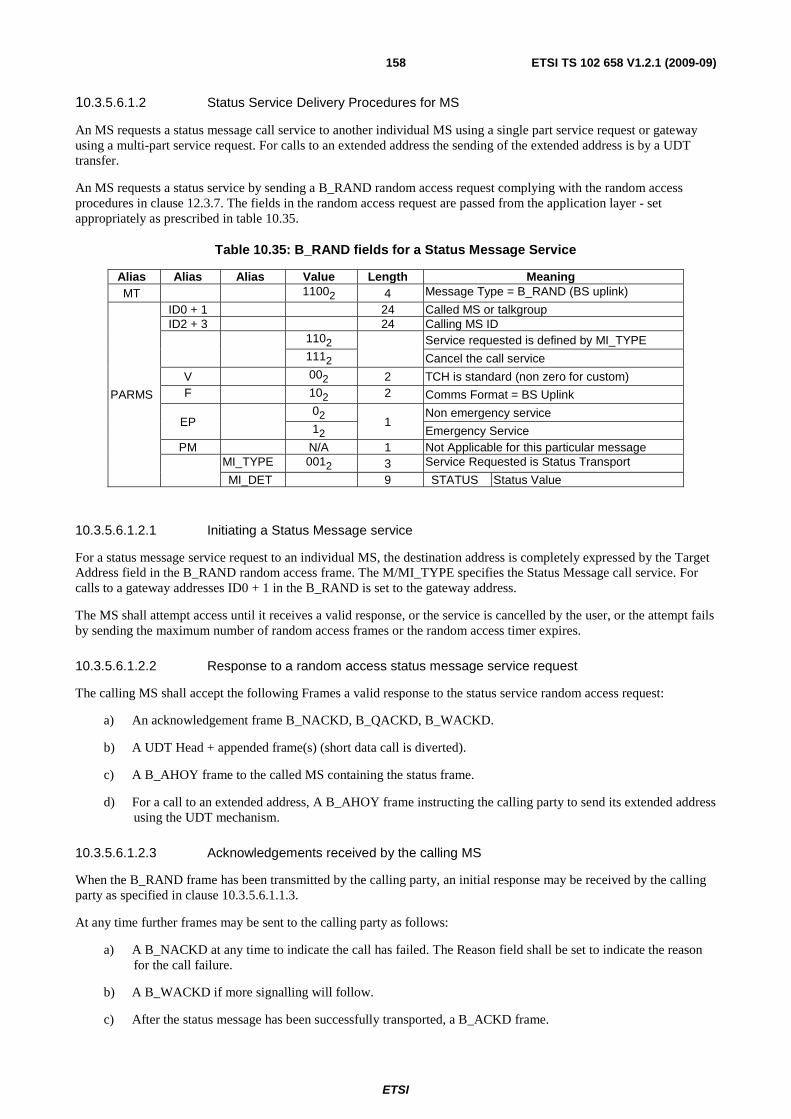
ETSI
ETSI TS 102 658 V1.2.1 (2009-09)158
10.3.5.6.1.2 Status Service Delivery Procedures for MS
An MS requests a status message call service to another individual MS using a single part service request or gateway using a multi-part service request. For calls to an extended address the sending of the extended address is by a UDT transfer.
An MS requests a status service by sending a B_RAND random access request complying with the random access procedures in clause 12.3.7. The fields in the random access request are passed from the application layer - set appropriately as prescribed in table 10.35.
Table 10.35: B_RAND fields for a Status Message Service
Alias Alias Alias Value Length Meaning MT 11002 4 Message Type = B_RAND (BS uplink)
PARMS
ID0 + 1 24 Called MS or talkgroup ID2 + 3 24 Calling MS ID
1102
Service requested is defined by MI_TYPE
1112 Cancel the call service
V 002 2 TCH is standard (non zero for custom) F 102 2 Comms Format = BS Uplink
EP 02
1 Non emergency service
12 Emergency Service PM N/A 1 Not Applicable for this particular message
MI_TYPE 0012 3 Service Requested is Status Transport
MI_DET 9 STATUS Status Value
10.3.5.6.1.2.1 Initiating a Status Message service
For a status message service request to an individual MS, the destination address is completely expressed by the Target Address field in the B_RAND random access frame. The M/MI_TYPE specifies the Status Message call service. For calls to a gateway addresses ID0 + 1 in the B_RAND is set to the gateway address.
The MS shall attempt access until it receives a valid response, or the service is cancelled by the user, or the attempt fails by sending the maximum number of random access frames or the random access timer expires.
10.3.5.6.1.2.2 Response to a random access status message service request
The calling MS shall accept the following Frames a valid response to the status service random access request:
a) An acknowledgement frame B_NACKD, B_QACKD, B_WACKD.
b) A UDT Head + appended frame(s) (short data call is diverted).
c) A B_AHOY frame to the called MS containing the status frame.
d) For a call to an extended address, A B_AHOY frame instructing the calling party to send its extended address using the UDT mechanism.
10.3.5.6.1.2.3 Acknowledgements received by the calling MS
When the B_RAND frame has been transmitted by the calling party, an initial response may be received by the calling party as specified in clause 10.3.5.6.1.1.3.
At any time further frames may be sent to the calling party as follows:
a) A B_NACKD at any time to indicate the call has failed. The Reason field shall be set to indicate the reason for the call failure.
b) A B_WACKD if more signalling will follow.
c) After the status message has been successfully transported, a B_ACKD frame.
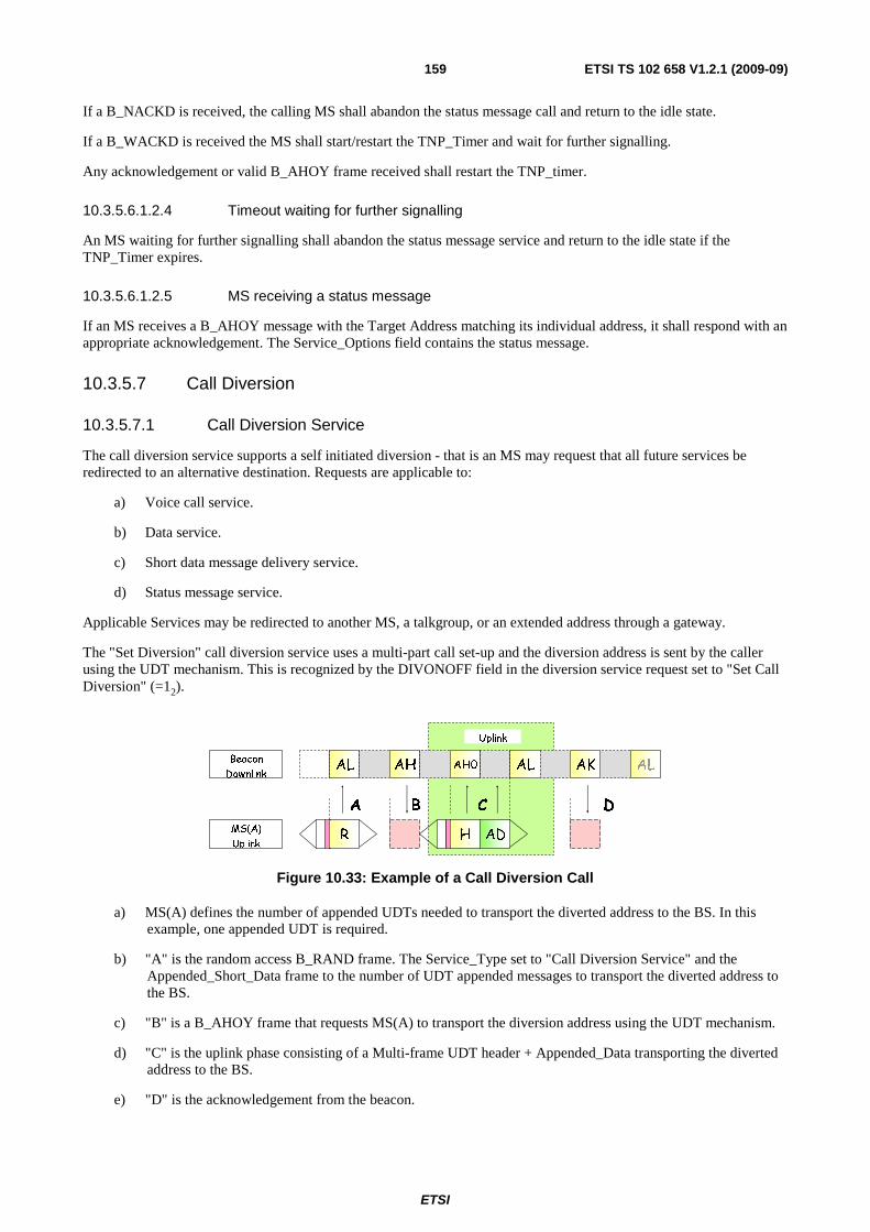
ETSI
ETSI TS 102 658 V1.2.1 (2009-09)159
If a B_NACKD is received, the calling MS shall abandon the status message call and return to the idle state.
If a B_WACKD is received the MS shall start/restart the TNP_Timer and wait for further signalling.
Any acknowledgement or valid B_AHOY frame received shall restart the TNP_timer.
10.3.5.6.1.2.4 Timeout waiting for further signalling
An MS waiting for further signalling shall abandon the status message service and return to the idle state if the TNP_Timer expires.
10.3.5.6.1.2.5 MS receiving a status message
If an MS receives a B_AHOY message with the Target Address matching its individual address, it shall respond with an appropriate acknowledgement. The Service_Options field contains the status message.
10.3.5.7 Call Diversion
10.3.5.7.1 Call Diversion Service
The call diversion service supports a self initiated diversion - that is an MS may request that all future services be redirected to an alternative destination. Requests are applicable to:
a) Voice call service.
b) Data service.
c) Short data message delivery service.
d) Status message service.
Applicable Services may be redirected to another MS, a talkgroup, or an extended address through a gateway.
The "Set Diversion" call diversion service uses a multi-part call set-up and the diversion address is sent by the caller using the UDT mechanism. This is recognized by the DIVONOFF field in the diversion service request set to "Set Call Diversion" (=12).
Uplink
AL AH ALAH0 AK
A B C
AL
MS(A)
Uplink
Beacon
Downlink
D
R H AD
Figure 10.33: Example of a Call Diversion Call
a) MS(A) defines the number of appended UDTs needed to transport the diverted address to the BS. In this example, one appended UDT is required.
b) "A" is the random access B_RAND frame. The Service_Type set to "Call Diversion Service" and the Appended_Short_Data frame to the number of UDT appended messages to transport the diverted address to the BS.
c) "B" is a B_AHOY frame that requests MS(A) to transport the diversion address using the UDT mechanism.
d) "C" is the uplink phase consisting of a Multi-frame UDT header + Appended_Data transporting the diverted address to the BS.
e) "D" is the acknowledgement from the beacon.
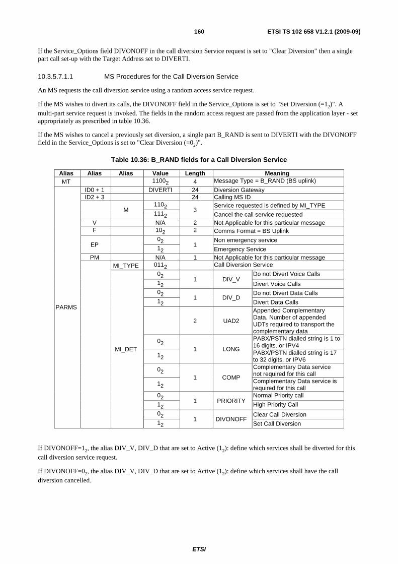
ETSI
ETSI TS 102 658 V1.2.1 (2009-09)160
If the Service_Options field DIVONOFF in the call diversion Service request is set to "Clear Diversion" then a single part call set-up with the Target Address set to DIVERTI.
10.3.5.7.1.1 MS Procedures for the Call Diversion Service
An MS requests the call diversion service using a random access service request.
If the MS wishes to divert its calls, the DIVONOFF field in the Service_Options is set to "Set Diversion (=12)". A multi-part service request is invoked. The fields in the random access request are passed from the application layer - set appropriately as prescribed in table 10.36.
If the MS wishes to cancel a previously set diversion, a single part B_RAND is sent to DIVERTI with the DIVONOFF field in the Service_Options is set to "Clear Diversion (=02)".
Table 10.36: B_RAND fields for a Call Diversion Service
Alias Alias Alias Value Length Meaning MT 11002 4 Message Type = B_RAND (BS uplink)
PARMS
ID0 + 1 DIVERTI 24 Diversion Gateway ID2 + 3 24 Calling MS ID
M 1102
3 Service requested is defined by MI_TYPE
1112 Cancel the call service requested V N/A 2 Not Applicable for this particular message F 102 2 Comms Format = BS Uplink
EP 02
1 Non emergency service
12 Emergency Service PM N/A 1 Not Applicable for this particular message
MI_TYPE 0112 Call Diversion Service
MI_DET
02 1 DIV_V
Do not Divert Voice Calls
12 Divert Voice Calls 02
1 DIV_D Do not Divert Data Calls
12 Divert Data Calls
2 UAD2
Appended Complementary Data. Number of appended UDTs required to transport the complementary data
02 1 LONG
PABX/PSTN dialled string is 1 to 16 digits. or IPV4
12 PABX/PSTN dialled string is 17 to 32 digits. or IPV6
02 1 COMP
Complementary Data service not required for this call
12 Complementary Data service is required for this call
02 1 PRIORITY
Normal Priority call
12 High Priority Call
02 1 DIVONOFF
Clear Call Diversion 12 Set Call Diversion
If DIVONOFF=12, the alias DIV_V, DIV_D that are set to Active (12): define which services shall be diverted for this call diversion service request.
If DIVONOFF=02, the alias DIV_V, DIV_D that are set to Active (12): define which services shall have the call diversion cancelled.

ETSI
ETSI TS 102 658 V1.2.1 (2009-09)161
Table 10.37: Field definitions for the Call Diversion Service
Diversion Address Target Address or Gateway LONG Individual MS Address MSI 02
talkgroup Address GPI 02
PSTN Address (1 to 16 dialled digits) PSTNI 02
PSTN Address (17 to 32 dialled digits) PSTNI 12
PABX Address(1 to 16 dialled digits) PABXI 02
PABX Address (17 to 32 dialled digits) PABXI 12
10.3.5.7.1.2 BS Procedures for the Call Diversion Service
An MS initiates a Set Call Diversion Service by random access addressed to the gateway identifier appropriate to the diverted destination - individual MS address, talkgroup, PTSN, PABX. The set call diversion service uses the multi-part call set-up. When the BS responds to the random access request it shall start timer (TNP_Timer). This timer shall be refreshed if the BS sends further call progress Frames to the calling party.
An MS initiates a Clear Call Diversion Service by random access addressed to the gateway identifier DIVERTI. The clear call diversion service uses the single-part call set-up. When the BS responds to the random access request it shall start timer (TNP_Timer). This timer shall be refreshed if the BS sends further call progress Frames to the calling party.
10.3.5.7.1.2.1 BS Response to a multi-part Set Call Diversion Service call set-up
To set call diversion service, the MS generates a random access diversion service request with the B_RAND fields set as table 10.36 and the DIVONOFF field set to Set Call Diversion (=12).
The frames that shall represent a valid response to the set call diversion service multi-part random access request are:
a) An acknowledgement frame B_NACKD, B_WACKD(reason=Wait).
b) A B_AHOY frame for the calling MS to send the diverted address using the UDT mechanism.
For b) The BS shall invoke the UDT procedure by sending a B_AHOY to the calling MS to send the diverted address information. For a call diversion to the PABX or PSTN the diverted address information shall be BCD digits. The LONG Flag field in the B_AHOY frame shall be copied from the LONG Flag field received from the MS B_RAND frame. If the BS does not successfully receive the UDT from the MS, the BS may repeat the B_AHOY, or transmit a B_NACKD to indicate failure of the call.
The gateway fields for B_AHOY Frames to upload the diverted address is prescribed in table 10.38.
Table 10.38: B_AHOY fields for the Set Call Diversion Service
Action Gateway Address
Remark
Send the individual MS Address MSI The calling party shall send the MS Individual diversion address
Send the talkgroup Address GPI The calling party shall send the MS talkgroup diversion address
Send PSTN digits PSTNI The calling party shall send BCD dialled digits Send PABX digits PABXI The calling party shall send BCD dialled digits
10.3.5.7.1.2.2 BS Response to a single-part Clear Call Diversion Service set-up
For the clear call diversion service, the MS generates a random access diversion service request with the B_RAND fields set as table 10.37 and the DIVONOFF field set to Clear Call Diversion (=02).
The frames that shall represent a valid response to the clear call diversion service multi-part random access request are:
a) An acknowledgement frame B_NACKD indicating that the service request has not succeeded.
b) B_WACKD(reason=Wait) further signalling to follow.
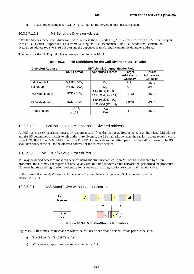
ETSI
ETSI TS 102 658 V1.2.1 (2009-09)162
c) An acknowledgement B_ACKD indicating that the service request has succeeded.
10.3.5.7.1.2.3 MS Sends the Diversion Address
After the MS has made a call diversion service request, the BS sends a B_AHOY frame to which the MS shall respond with a UDT Header + Appended_Data frame(s) using the UDT mechanism. The UDT header shall contain the destination address type (MS, PSTN etc) and the appended frame(s) shall contain the diversion address.
The fields for the UDT uplink Header are specified in table 10.39.
Table 10.39: Field Definitions for the Call Diversion UDT Header
Diversion Address UDT Uplink Channel Header Field UDT Format Appended Frames Target
Address or Gateway
Source Address or
Gateway Individual MS MS ID - 0002 002 MSI MS ID Talkgroup MS ID - 0002 002 GPI MS ID
PSTN destination BCD - 0102 1 to 16 digits - 002
17 to 32 digits - 012 PSTNI MS ID
PABX destination BCD - 0102 1 to 16 digits - 002
17 to 32 digits - 012 PABXI MS ID
IP destination IP - 1102 or 1112
IPV4 IPV6 IPI MS ID
10.3.5.7.2 Call set-up to an MS that has a Diverted address
An MS makes a service access request by random access. If the destination address selected is an individual MS address and the BS determines that calls to this address are diverted, the BS shall acknowledge the random access request with a B_WACK, ID0 + 1 = Calling MS, ID2 + 3 = DIVERTI to indicate to the calling party that the call is diverted. The BS shall then connect the call to the diverted address for the selected service.
10.3.5.8 MS Stun/Revive Procedures
MS may be denied access to most call services using the stun mechanism. If an MS has been disabled by a stun procedure, the MS may not request nor receive any user initiated services on the network that performed the procedure. However hunting and registration, authentication, stun/unstun and registration services shall remain active.
In the present document, MS shall only be stunned/revived from a BS gateway STUNI as described in clause 10.3.5.8.1.1.
10.3.5.8.1 MS Stun/Revive without authentication
AL AL
A
AH AL
MS(A)
Uplink
Beacon
Downlink
B
AK
Figure 10.34: MS Stun/Revive Procedure
Figure 10.34 illustrates the mechanism where the MS does not demand authentication prior to the stun.
a) The BS sends a B_AHOY at "A".
b) MS makes an appropriate acknowledgement at "B".
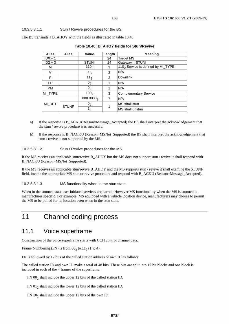
ETSI
ETSI TS 102 658 V1.2.1 (2009-09)163
10.3.5.8.1.1 Stun / Revive procedures for the BS
The BS transmits a B_AHOY with the fields as illustrated in table 10.40.
Table 10.40: B_AHOY fields for Stun/Revive
Alias Alias Value Length Meaning ID0 + 1 24 Target MS ID2 + 3 STUNI 24 Gateway = STUNI
M 1102 3 1102 Service is defined by MI_TYPE
V 002 2 N/A
F 112 2 Downlink
EP 02 1 N/A
PM 02 1 N/A
MI_TYPE 1002 3 Complementary Service
MI_DET
000 00002 7 N/A
STUNF 02
1 MS shall stun
12 MS shall unstun
a) If the response is B_ACKU(Reason=Message_Accepted) the BS shall interpret the acknowledgement that the stun / revive procedure was successful.
b) If the response is B_NACKU (Reason=MSNot_Supported) the BS shall interpret the acknowledgement that stun / revive is not supported by the MS.
10.3.5.8.1.2 Stun / Revive procedures for the MS
If the MS receives an applicable stun/revive B_AHOY but the MS does not support stun / revive it shall respond with B_NACKU (Reason=MSNot_Supported).
If the MS receives an applicable stun/revive B_AHOY and the MS supports stun / revive it shall examine the STUNF field, invoke the appropriate MS stun or revive procedure and respond with B_ACKU (Reason=Message_Accepted).
10.3.5.8.1.3 MS functionality when in the stun state
When in the stunned state user initiated services are barred. However MS functionality when the MS is stunned is manufacturer specific. For example, MS equipped with a vehicle location device, manufacturers may choose to permit the MS to be polled for its location even when in the stun state.
11 Channel coding process
11.1 Voice superframe Construction of the voice superframe starts with CCH control channel data.
Frame Numbering (FN) is from 002 to 112 (1 to 4).
FN is followed by 12 bits of the called station address or own ID as follows:
The called station ID and own ID make a total of 48 bits. These bits are split into 12 bit blocks and one block is included in each of the 4 frames of the superframe.
FN 002 shall include the upper 12 bits of the called station ID.
FN 012 shall include the lower 12 bits of the called station ID.
FN 102 shall include the upper 12 bits of the own ID.
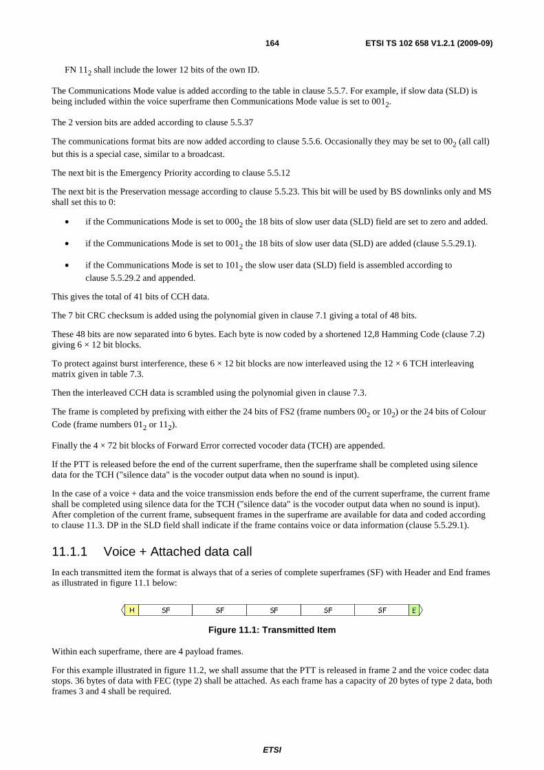
ETSI
ETSI TS 102 658 V1.2.1 (2009-09)164
FN 112 shall include the lower 12 bits of the own ID.
The Communications Mode value is added according to the table in clause 5.5.7. For example, if slow data (SLD) is being included within the voice superframe then Communications Mode value is set to 0012.
The 2 version bits are added according to clause 5.5.37
The communications format bits are now added according to clause 5.5.6. Occasionally they may be set to 002 (all call)
but this is a special case, similar to a broadcast.
The next bit is the Emergency Priority according to clause 5.5.12
The next bit is the Preservation message according to clause 5.5.23. This bit will be used by BS downlinks only and MS shall set this to 0:
• if the Communications Mode is set to 0002 the 18 bits of slow user data (SLD) field are set to zero and added.
• if the Communications Mode is set to 0012 the 18 bits of slow user data (SLD) are added (clause 5.5.29.1).
• if the Communications Mode is set to 1012 the slow user data (SLD) field is assembled according to
clause 5.5.29.2 and appended.
This gives the total of 41 bits of CCH data.
The 7 bit CRC checksum is added using the polynomial given in clause 7.1 giving a total of 48 bits.
These 48 bits are now separated into 6 bytes. Each byte is now coded by a shortened 12,8 Hamming Code (clause 7.2) giving 6 × 12 bit blocks.
To protect against burst interference, these 6 × 12 bit blocks are now interleaved using the 12 × 6 TCH interleaving matrix given in table 7.3.
Then the interleaved CCH data is scrambled using the polynomial given in clause 7.3.
The frame is completed by prefixing with either the 24 bits of FS2 (frame numbers 002 or 102) or the 24 bits of Colour
Code (frame numbers 012 or 112).
Finally the 4 × 72 bit blocks of Forward Error corrected vocoder data (TCH) are appended.
If the PTT is released before the end of the current superframe, then the superframe shall be completed using silence data for the TCH ("silence data" is the vocoder output data when no sound is input).
In the case of a voice + data and the voice transmission ends before the end of the current superframe, the current frame shall be completed using silence data for the TCH ("silence data" is the vocoder output data when no sound is input). After completion of the current frame, subsequent frames in the superframe are available for data and coded according to clause 11.3. DP in the SLD field shall indicate if the frame contains voice or data information (clause 5.5.29.1).
11.1.1 Voice + Attached data call
In each transmitted item the format is always that of a series of complete superframes (SF) with Header and End frames as illustrated in figure 11.1 below:
SFH SF SF ESFSF
Figure 11.1: Transmitted Item
Within each superframe, there are 4 payload frames.
For this example illustrated in figure 11.2, we shall assume that the PTT is released in frame 2 and the voice codec data stops. 36 bytes of data with FEC (type 2) shall be attached. As each frame has a capacity of 20 bytes of type 2 data, both frames 3 and 4 shall be required.

ETSI
ETSI TS 102 658 V1.2.1 (2009-09)165
payload frame 384 (80mS)payload frame 384 (80mS)payload frame 384 (80mS)payload frame 384 (80mS)
FS2 CCH TCH TCH TCH TCH
Superframe (320mS)
CC CCH TCH TCH TCH TCH FS2 CCH TCH TCH TCH TCH CC CCH TCH TCH TCH TCH
Figure 11.2: Transmitted Item Example
The SLD field in each of these frames is composed as illustrated in figure 11.3:
Frame 1: with voice payload
Reserved DP Format Cont. Data length (bytes) 000002 002 4 bits 12 0000002
Frame 2: with voice payload ending in this frame
Reserved DP Format Cont. Data length (bytes) 000002 002 4 bits 12 0000002
Frame 3: with data payload starting in this frame
Reserved DP Format Cont. Data length (bytes) 000002 112 4 bits 02 0101002 (20 bytes in this frame)
Frame 4: with data payload ending in this frame
Reserved DP Format Cont. Data length (bytes) 000002 112 4 bits 12 0100002 (16 bytes in this frame)
Figure 11.3: Frame Construction
Notes for TCH payload:
• In frame 2 the voice codec data ends when the PTT is released. "Silence data" is used to complete the TCH payload of frame 2 as previously stated.
• In frame 4 the 16 bytes of data is not enough to complete the frame. Therefore 4 bytes of dummy data (i.e. zeros) is attached to complete the TCH payload of frame 4. The TCH payload is coded according to clause 9.3. The receiving party knows that there are 4 bytes of dummy data as the SLD data length field indicates that only 16 of the 20 bytes are valid data.
Table 11.1: CM, SLD, MI use
Communication mode SLD field (CCH) see clause 5.9 MI field (Header) see clause 5.10 0002 Voice Comm ALL "02" (No user data) Header Type
0012 Voice + User SLD User Slow Data (clause 5.5.29.1) Header Type
0102 Data Type 1 TCH data information (clause 5.5.29.2) Header Type (see note) / Data Format
0112 Data Type 2 TCH data information (clause 5.5.29.2) Header Type (see note) / Data Format
1002 Data Type 3 --------- Header Type (see note) / pdS,pdM
1012 Voice and attached Data Type 2
TCH data information Header Type
NOTE: Use Extended Header (clause 11.1).

ETSI
ETSI TS 102 658 V1.2.1 (2009-09)166
8 bits
CCH DATA
41 bits
8 bits8 bits
8 bits4
bits8 bits
4
bits8 bits
4
bits
72 bits
1 13 25 37 49 61
61read
1
2 2 14 26 38 50 62
12 12 24 36 48 60 72
write
after interleave CCH DATA
72 bits
Scramble x9 + x
5 + 1
FS2 / CC
24 bits
FS2 / CC
24 bits
CCH
72 bits
FEC (12,8)
Shortened Hamming
Interleave
12 x 6
384 bits
48 bits
CCH DATA
41 bits
CRC
7 bits
Add CRC
Divide
TCH
72 bits
TCH
72 bits
TCH
72 bits
TCH
72 bits
TCH
72 bits
TCH
72 bits
TCH
72 bits
TCH
72 bits
Figure 11.4 : Voice frame coding

ETSI
ETSI TS 102 658 V1.2.1 (2009-09)167
11.2 Type 1 data superframe A characteristic of a type 1 data superframe is that no error correction is applied to the user data.
Construction of the type 1 data superframe starts with CCH control channel data.
Frame Numbering (FN) is from 002 to 112 (1 to 4)
FN is followed by 12 bits of the called station address or own ID as follows:
The called station ID and own ID make a total of 48 bits. These bits are split into 12 bit blocks and one block is included in each of the 4 frames of the superframe.
FN 002 shall include the upper 12 bits of the called station ID.
FN 012 shall include the lower 12 bits of the called station ID.
FN 102 shall include the upper 12 bits of the own ID.
FN 112 shall include the lower 12 bits of the own ID.
The Communications Mode, 0102 is added (clause 5.5.7).
The 2 version bits are added according to clause 5.5.37.
The communications format bits are now added according to clause 5.8. Occasionally they may be set to 002 (all call)
but this is a special case, similar to a broadcast.
The next bit is the Emergency Priority according to clause 5.5.12
The next bit is the Preservation message according to clause 5.5.23. This bit will be used by BS downlinks only and MS shall set this to 0.
Then there are the 18 bits of the slow user data field (SLD). These bits are set according to clause 5.5.29.2 depending on the data to be transmitted.
This gives the total of 41 bits of CCH data.
The 7 bit CRC checksum is added using the polynomial given in clause 7.1 giving a total of 48 bits.
These 48 bits are now separated into 6 bytes. Each byte is now coded by a shortened 12,8 Hamming Code (clause 7.2) giving 6 × 12 bit blocks.
To protect against burst interference, these 6 × 12 bit blocks are now interleaved using the 12 × 6 TCH interleaving matrix given in table 7.3.
Next the 288 bit block of uncorrected user data are attached.
Finally the interleaved CCH data and attached data blocks are scrambled using the polynomial given in clause 7.3.
The frame is completed by prefixing with either the 24 bits of FS2 (frame numbers 002 or 102) or the 24 bits of Colour
Code (frame numbers 012 or 112).
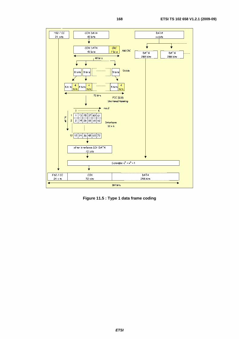
ETSI
ETSI TS 102 658 V1.2.1 (2009-09)168
8 bits
CCH DATA
41 bits
CCH DATA
41 bits
CRC
7 bits
48 bits
8 bits8 bits
8 bits4
bits8 bits
4
bits8 bits
4
bits
72 bits
1 13 25 37 49 61
61read
1
2 2 14 26 38 50 62
12 12 24 36 48 60 72
write
after interleave CCH DATA
72 bits
Scramble x9 + x
5 + 1
FS2 / CC
24 bits
FS2 / CC
24 bits
CCH
72 bits
FEC (12,8)
Shortened Hamming
Interleave
12 x 6
384 bits
Add CRC
Divide
DATA
xxbits
DATA
288 bits
DATA
288 bits
DATA
288 bits
Figure 11.5 : Type 1 data frame coding

ETSI
ETSI TS 102 658 V1.2.1 (2009-09)169
11.3 Type 2 Data superframe Construction of the type 2 data superframe starts with CCH control channel data.
Frame numbering (FN) is from 002 to 112 (1 to 4).
FN is followed by 12 bits of the called station address or own ID as follows:
The called station ID and own ID make a total of 48 bits. These bits are split into 12 bit blocks and one block is included in each of the 4 frames of the superframe.
FN 002 shall include the upper 12 bits of the called station ID.
FN 012 shall include the lower 12 bits of the called station ID.
FN 102 shall include the upper 12 bits of the own ID.
FN 112 shall include the lower 12 bits of the own ID.
The Communications Mode, 0112 is added (clause 5.5.7).
The 2 version bits are added according to clause 5.5.37.
The communications format bits are now added according to clause 5.8. Occasionally they may be set to 002 (all call)
but this is a special case, similar to a broadcast.
The next bit is the Emergency Priority according to clause 5.5.12.
The next bit is the Preservation message according to clause 5.5.23. This bit will be used by BS downlinks only and MS shall set this to 0.
Finally there are the 18 bits of the slow user data field (SLD). These bits are set according to clause 5.5.29.2 depending on the data to be transmitted.
This gives the total of 41 bits of CCH data.
The 7 bit CRC checksum is added using the polynomial given in clause 7.1 giving a total of 48 bits.
These 48 bits are now separated into 6 bytes. Each byte is now coded by a shortened 12,8 Hamming Code (clause 7.2) giving 6 × 12 bit blocks.
To protect against burst interference, these 6 × 12 bit blocks are now interleaved using the 12 × 6 TCH interleaving matrix given in clause 7.4.
The user data is broken down into 5 byte blocks (40 bits) to which 1 bit of null data (i.e. set to 02) is attached. Four of
these 41 bit blocks shall be allocated to each frame.
The 7 bit CRC checksum is added to each 41 bit block using the polynomial given in clause 7.1 giving a total of 48 data bits.
These 48 data bits are now separated into 6 bytes. Each byte is now coded by a shortened 12,8 Hamming Code (clause 7.2) giving 6 × 12 bit blocks.
To protect against burst interference, these 6 × 12 bit blocks are now interleaved using the 12 × 6 TCH interleaving matrix given in table 7.4.
Next four of the 72 bit coded data blocks are concatenated to the interleaved CCH data and scrambled using the polynomial given in clause 7.3.
The frame is completed by prefixing with either the 24 bits of FS2 (frame numbers 002 or 102) or the 24 bits of Colour
Code (frame numbers 012 or 112).
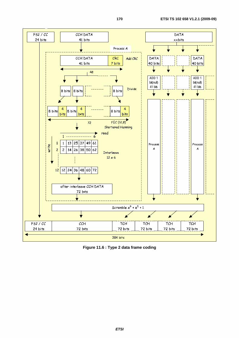
ETSI
ETSI TS 102 658 V1.2.1 (2009-09)170
384 bits
DATA
xxbits
8 bits
CCH DATA
41 bits
DATA
40 bits
DATA
40 bits
ADD 1 bit(null)41 bits
Process
A
Process
A
8 bits8 bits
8 bits4
bits8 bits
4
bits8 bits
4
bits
72
ADD 1 bit(null)41 bits
1 13 25 37 49 61
61read
1
2 2 14 26 38 50 62
12 12 24 36 48 60 72
write
after interleave CCH DATA
72 bits
Scramble x9 + x
5 + 1
FS2 / CC
24 bits
FS2 / CC
24 bits
CCH
72 bits
TCH
72 bits
TCH
72 bits
TCH
72 bits
TCH
72 bits
FEC (12,8)
Shortened Hamming
Interleave
12 x 6
Process A
CCH DATA
41 bits
CRC
7 bits
48
Add CRC
Divide
Figure 11.6 : Type 2 data frame coding
ETSI
ETSI TS 102 658 V1.2.1 (2009-09)171
11.4 Type 3 (Packet) Data frame Construction of the type 3 Packet starts with the PAR (parameter) data.
The packet burst can consist of up to 8 data frames. The current data frame number (N) is from 0002 to 1112.
N is followed by 8 bits that give the total number of data bytes contained in the current burst.
This is followed by 14 dummy bits that are set to zero.
The next 16 bits are the CRC for the data field contained in this burst.
The 7 bit CRC checksum is added to these 41 bits using the polynomial given in clause 7.1 giving a total of 48 bits.
These 48 data bits are now separated into 6 bytes. Each byte is now coded by a shortened 12,8 Hamming Code (clause 7.2) giving 6 × 12 bit blocks.
To protect against burst interference, these 6 × 12 bit blocks are now interleaved using the 12 × 6 TCH interleaving matrix given in clause 7.4.
Next the associated data frames are concatenated to the interleaved PAR data and scrambled using the polynomial given in clause 7.3.
The frame is completed by prefixing the 24 bits of Colour Code.
NOTE: The packet data format used in these frames is indicated by the Message Information (MI) contained in the Packet data Header. See clause 9.3.
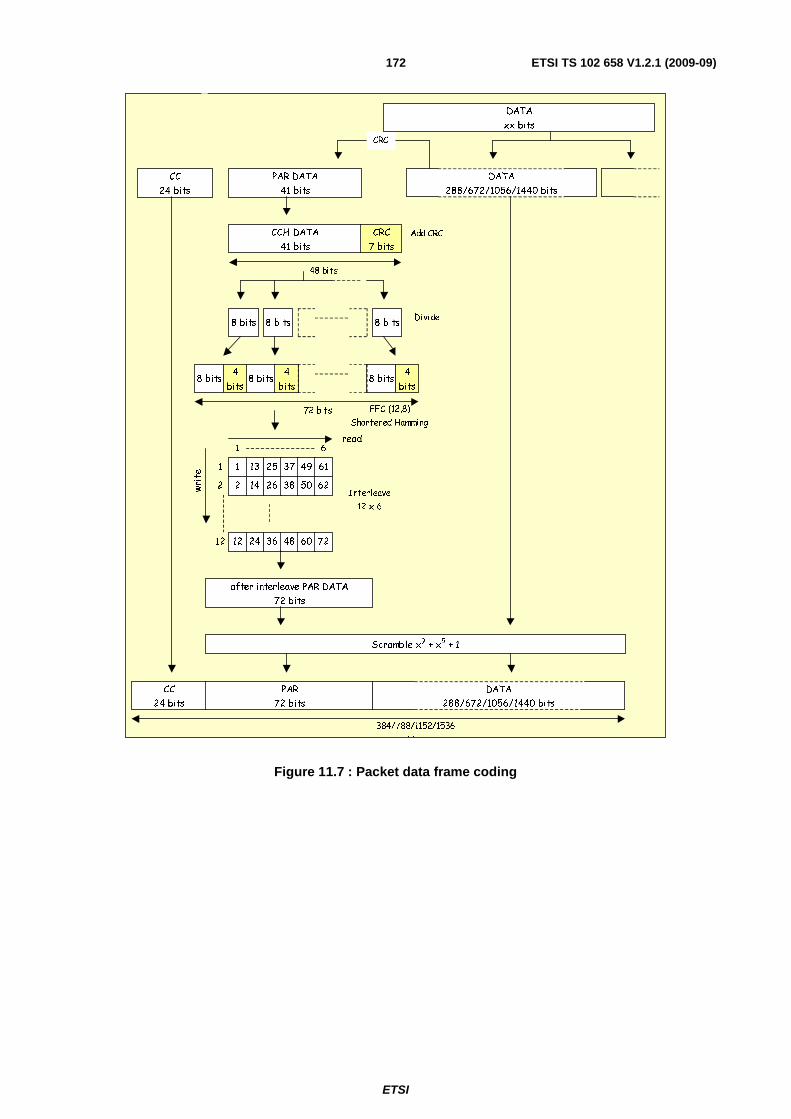
ETSI
ETSI TS 102 658 V1.2.1 (2009-09)172
8 bits
PAR DATA
41 bits
CCH DATA
41 bits
CRC
7 bits
48 bits
8 bits8 bits
8 bits4
bits8 bits
4
bits8 bits
4
bits
72 bits
1 13 25 37 49 61
61read
1
2 2 14 26 38 50 62
12 12 24 36 48 60 72
write
after interleave PAR DATA
72 bits
Scramble x9 + x
5 + 1
CC
24 bits
CC
24 bits
PAR
72 bits
DATA
288/672/1056/1440 bits
FEC (12,8)
Shortened Hamming
Interleave
12 x 6
384/788/1152/1536
bi
Add CRC
Divide
DATA
288/672/1056/1440 bits
CRC
DATA
xx bits
Figure 11.7 : Packet data frame coding
ETSI
ETSI TS 102 658 V1.2.1 (2009-09)173
11.5 Messages Construction of a Message starts with the Message Information (MI) bits.
First there are 4 bits allocated to Message Type (MT) which is selected according to clause 5.5.20.
MT is followed by the 24 bits of the called station ID. To this the 24 bits of the own ID is added.
The Communications Mode value is added according to the table in clause 5.5.7.
The 2 version bits are added according to clause 5.5.37.
The communications format bits are now added according to clause 5.5.6. Occasionally they may be set to 002 (all call)
but this is a special case, similar to a broadcast.
The next bit is the Emergency Priority according to clause 5.5.12.
The next bit is the Preservation message according to clause 5.5.23. This bit will be used by BS downlinks only and MS shall set this to 0.
Finally there are the 11 bits of Message Information (MI) that are made up of 3 MI Type bits and 8 MI_Detail bits as described in clause 5.5.19 (see table 11.1).
This gives the total of 72 bits of MI data.
The 8 bit CRC checksum is added using the polynomial given in clause 7.1 giving a total of 80 bits.
These 80 bits are now separated into 10 bytes. Each byte is now coded by a shortened 12,8 Hamming Code (clause 7.2) giving 10 × 12 bit blocks.
To protect against burst interference, these 10 × 12 bit blocks are now interleaved using the 12 × 10 MI interleaving matrix given in clause 7.4.
Then the interleaved MI data is scrambled using the polynomial given in clause 7.3.
The 24 bit Colour Code is concatenated to the MI data and then the MI data is repeated after the CC.
The message is completed by prefixing with the 48 bit FS1 synchronization sequence (see note 1) and then prefixing the synchronization sequence with a minimum of 72 bits of preamble.
Table 11.1: Use of Message Information
Use Purpose Clause Powersave Indicate normal or extended header type 5.5.19.1 T1 or T2 Data Indicate the type of data (complementary
service) 5.5.19.2
T3 Data (Packet) Indicate data frame size and number of frames 5.5.19.3 Acknowledgements Indicate ACK or NACK and reason 5.5.19.5 System request System response Delivery Header
MI Type defines the purpose MI_Detail is not used and set to 0000 00002
5.5.19.4
Broadcast 5.5.19.6 BS Command Header
MI type defines the purpose MI_Detail may give extra parameters
5.5.19.7
Ahoys 5.5.19.8
NOTE 1: In the case where this is a Packet Data header, the 48 bit FS4 synchronization sequence is used, H10 replaces M10, H11 replaces M11 and HT replaces MT. Normally receiving stations determine the call type from the Header Information but techniques such as determination by FS type (as used by ETS 300 230 [i.1], MPT 1327 [i.2] and others) are equally valid.
NOTE 2: The preamble and FS1 is not present for a beacon channel message frame.

ETSI
ETSI TS 102 658 V1.2.1 (2009-09)174
8 bits
MI
72 bits
MI
72 bits
CRC
8 bits
80 bits
8 bits8 bits
8 bits4
bits8 bits
4
bits8 bits
4
bits
120 bits
1 13 25 37 49 61
1read
1
2 2 14 26 38 50 62
12 12 24 36 48 60 72
write
after interleave CI DATA
120 bits
Scramble x9 + x
5 + 1
Preamble
>=72 bits
MI0
120 bits
FEC (12,8)
Shortened Hamming
Interleave
12 x 10
Add CRC
Divide
FS1
48 bits
10
911
0
10
12
0
Preamble
>=72 bits
FS1
48 bits
CC
24 bits
MI1
120 bits
Scramble x9 + x
5 + 1
after interleave CI DATA
120 bits
Copy
CC
24 bits
>=384 bits
Figure 11.8 : Message coding

ETSI
ETSI TS 102 658 V1.2.1 (2009-09)175
11.6 End frames Construction of the End frame starts with the 17 bits of End data.
The end data starts with the End Type (ET) which is either 002 (normal end frame) or 012 (end frame with status
message).
The next 2 bit are the acknowledgement request (ARQ). 002 signifies that no acknowledgement is requested and 01
requires an acknowledgement.
The next 4 bits define any Tx_Wait time (WAIT) using the values given in clause 5.5.34.
5 bit of status message shall then follow if ET has been set to 012 (or 5 bits of dummy data if ET = 002).
Finally the 4 reserved bits are set to 00002.
The 7 bit CRC checksum is added using the polynomial given in clause 7.1 giving a total of 24 bits.
These 24 bits are now separated into 3 bytes. Each byte is now coded by a shortened 12,8 Hamming Code (clause 7.2) giving 3 × 12 bit blocks. These 36 bits are now repeated and the total 72 bits are scrambled using the polynomial given in clause 7.3.
Finally the 24 bit FS3 synchronization sequence is prefixed to these end data bits.
8 bits
END DATA
17 bits
8 bits8 bits
8 bits4
bits8 bits
4
bits
36 bits
END DATA
36 bits
Scramble x9 + x
5 + 1
FEC (12,8)
Shortened Hamming
Divide
FS3
24 bits
FS3
24 bits
Copy
CRC
7 bits
24 bits
Add CRCEND DATA
17 bits
8 bits4
bits
END DATA
36 bits
END DATA
36 bits
END DATA
36 bits
96 bits
Figure 11.9 : End frame coding

ETSI
ETSI TS 102 658 V1.2.1 (2009-09)176
11.7 SYScast Frames SYScast frames are transmitted by a Mode 3 Beacon Channel.
Construction of the SYScast frame starts with the 17 bits of SYScast1, SYScast2 and SYScast 3 data.
The SYScast1, SYScast2 and SYScast3 fields are defined in clause 5.5.32.
For each SYScast frame:
The 7 bit CRC checksum is added using the polynomial given in clause 7.1 giving a total of 24 bits.
These 24 bits are now separated into 3 bytes. Each byte is now coded by a shortened 12,8 Hamming Code (clause 7.2) giving 3 × 12 bit blocks. These 36 bits are now repeated and the total 72 bits are scrambled using the polynomial given in clause 7.3.
The three blocks of 72 bits are concatenated to produce a 216 bit message.
8 bits
SYScast1
17 bits
8 bits8 bits
8
bits
4
bits
8
bits
4
bits
36 bits
Scramble x9 + x
5 + 1
FEC (12,8)
Shortened Hamming
Divide
Copy
CRC
7 bits
24 bits
Add CRCSYScast1
17 bits
8
bits
4
bits
SYScast1
36 bits
SYScast1
36 bits
SYScast1
36 bits
72 bits
SYScast1
36 bits
8 bits
SYScast2
17 bits
8 bits8 bits
8
bits
4
bits
8
bits
4
bits
36 bits
Scramble x9 + x
5 + 1
FEC (12,8)
Shortened Hamming
Divide
Copy
CRC
7 bits
24 bits
Add CRCSYScast2
17 bits
8
bits
4
bits
SYScast2
36 bits
SYScast2
36 bits
SYScast2
36 bits
72 bits
SYScast2
36 bits
8 bits
SYScast3
17 bits
8 bits8 bits
8
bits
4
bits
8
bits
4
bits
36 bits
Scramble x9 + x
5 + 1
FEC (12,8)
Shortened Hamming
Divide
Copy
CRC
7 bits
24 bits
Add CRCSYScast3
17 bits
8
bits
4
bits
SYScast3
36 bits
SYScast3
36 bits
SYScast3
36 bits
SYScast3
36 bits
72 bits
Figure 11.10 : SYScast frame coding
12 Channel access Systems compliant with the present document may operate in one of three Modes. Mode 1 systems are peer-to-peer described in clause 12.1. Clause 12.2 describes Mode 2 centralized repeater systems. Mode 3 systems are fully managed systems intended for a high throughput of traffic supporting a number of traffic channels. In addition to describing the basic channel access for Mode 3 systems, the additional services needed for effective system management are also described in clause 12.3.
Where an MS has been solicited to transmit a response, the preamble at the start of the transmission shall be timed to conform with figure 12.1. Figure 12.1 shows the case where MS(A) (or BS) has transmitted a message that solicits a response from MS(B). The MS transmitting the response shall send its first bit of preamble 30ms from the last bit of the message that solicited the response. The diagram does not imply any limitation on the start of the MS Tx RF power ramp which does not need to have attained full power for the first 24 bits of the preamble.
The response shall be sent irrespective of whether the channel is "Idle" or "Busy".
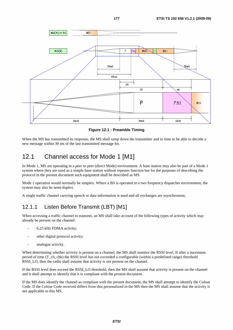
ETSI
ETSI TS 102 658 V1.2.1 (2009-09)177
MS(A) or BS
MS(B)
MI1
P MI1MI0FS1 cc
30mS
45mS
P MI1
15mS
FS1
10mS30mS
72 48
30mS
24
Figure 12.1 : Preamble Timing
When the MS has transmitted its response, the MS shall ramp down the transmitter and in time to be able to decode a new message within 30 ms of the last transmitted message bit.
12.1 Channel access for Mode 1 [M1] In Mode 1, MS are operating in a peer to peer (direct Mode) environment. A base station may also be part of a Mode 1 system where they are used as a simple base station without repeater function but for the purposes of describing the protocol in the present document such equipment shall be described as MS.
Mode 1 operation would normally be simplex. Where a BS is operated in a two frequency dispatcher environment, the system may also be semi-duplex.
A single traffic channel carrying speech or data information is used and all exchanges are asynchronous.
12.1.1 Listen Before Transmit (LBT) [M1]
When accessing a traffic channel to transmit, an MS shall take account of the following types of activity which may already be present on the channel:
- 6,25 kHz FDMA activity;
- other digital protocol activity;
- analogue activity.
When determining whether activity is present on a channel, the MS shall monitor the RSSI level. If after a maximum period of time (T_ch_chk) the RSSI level has not exceeded a configurable (within a predefined range) threshold RSSI_LO, then the radio shall assume that activity is not present on the channel.
If the RSSI level does exceed the RSSI_LO threshold, then the MS shall assume that activity is present on the channel and it shall attempt to identify that it is compliant with the present document.
If the MS does identify the channel as compliant with the present document, the MS shall attempt to identify the Colour Code. If the Colour Code received differs from that personalized in the MS then the MS shall assume that the activity is not applicable to this MS.

ETSI
ETSI TS 102 658 V1.2.1 (2009-09)178
12.1.2 Hang time messages and timers [M1]
12.1.2.1 Definition [M1]
A voice call consists of a series of speech items separated by gaps known as "call hang time periods". A talkgroup data call consists of one or more data items.
As the protocol is inherently asynchronous, these gaps are of random duration but it is possible for an MS involved in a talkgroup call to define a minimum call hang time period using the Tx_Wait parameter transmitted at the end of each item in the END frame. The Tx_Wait timer commences immediately after the last bit of the END frame of the transmission that announces a Tx_Wait period.
12.1.2.2 Action by receiving stations [M1]
When a transmitting MS involved in a talkgroup call announces a none zero Tx_Wait time then the next item shall not be permitted to start during this Tx_Wait time irrespective of any polite or impolite criteria employed.
During the TX_Wait period, MS shall monitor the channel for a possible break-in request.
Where an MS receives an emergency break-in request during the announced Tx_Wait time then the MS shall generate a suitable audible prompt to the user to leave the channel free for the station that has requested the channel.
12.1.2.3 Call duration timers [M1]
12.1.2.3.1 Item Duration Timer for Voice Calls [M1]
For a voice call, MSs shall maintain a traffic channel transmit TimeOut timer (TV_Item) which limits the time of a single voice transmission item. This timer shall be set to the value of TV_Item seconds whenever the PTT key is pressed and counts down to zero.
If the transmit TimeOut timer expires, then the MS shall complete the current superframe, transmit an END frame then stop transmitting. The MS may not re-transmit until PTT has been released and pressed again.
12.1.2.3.2 Item Duration Timer for Data Calls [M1]
MSs shall maintain a data maximum item duration timer TD_Item. If the MS reaches the maximum item duration TD_Item, the MS shall discontinue the item immediately and indicate to the application layer that the item was not successfully transmitted.
12.1.3 Transmit admit criteria [M1]
12.1.3.1 Channel "Politeness" [M1]
While an MS is party to a voice call, it may transmit irrespective of whether the channel is "Idle" or "Busy" with 6,25 kHz FDMA activity pertaining to the same voice call but may not transmit if a Tx_Wait time has been invoked and the timer is running. However, for all other situations including data transmissions, MSs shall be configurable to employ the following levels of "politeness" on a channel:
a) Polite to own Talkgroup: The MS shall refrain from transmitting on a channel while the channel is "Busy" already present on the channel, the MS shall transmit regardless, with other 6,25 kHz FDMA activity from MSs within its own talkgroup. For all other types of activity.
b) Polite to own Colour Code: The MS shall refrain from transmitting on a channel while the channel is "Busy" with other 6,25 kHz FDMA activity from MSs using the same Colour Code. For all other types of activity already present on the channel, the MS shall transmit regardless.
c) Impolite: The radio shall transmit on a channel regardless of any other activity (either 6,25 kHz FDMA or otherwise) already present on the channel.
On a given channel, not all features may be supported the same level of politeness. So for example, voice transmissions may be configured to be "impolite" while packet data transmissions are configured to be "polite".
ETSI
ETSI TS 102 658 V1.2.1 (2009-09)179
12.1.3.2 General Timing [M1]
Where an MS has been solicited to transmit a response, it shall conform to the timing specified in clause 12.
If an MS is soliciting a response and does not receive it, there are two possibilities:
a) The message that solicited the response was not received by the called party.
b) The message that solicited the response was received by the polled party, an acknowledgement was sent by the polled party but the acknowledgement was not received by the calling party.
If a repeat message is sent by the calling party, any repeat message shall be delayed to account for case b) above.
12.1.3.3 Transmission re-tries [M1]
Certain transmissions solicit responses and where these responses are not received (e.g. due to collisions, interference, etc.) the transmitting entity may repeat the original transmission NM1_Rep times.
12.1.3.4 Emergency channel access procedures [M1]
In systems where emergency channel access is required, it shall be implemented as follows:
a) MS shall be specifically configured to permit emergency calls;
b) If the channel is idle, an MS may make an emergency call. While an emergency call is in progress the MS engaged in the call shall set Tx_Wait = 0;
c) An active emergency call shall not be interrupted by a new emergency call;
d) If, at the time emergency access is required the channel is occupied by a normal priority call, emergency channel access shall be by means of a pre-keyed break in request which shall be transmitted during the Tx_Wait delay announced by the last END frame;
e) MS who were previously involved in a call shall continue to decode the message information (MI) of the frames received and shall not transmit as they are no longer party to this call. Such MS may also provide some indication to the user that the channel has been pre-empted for an emergency call. MS that have been pre-empted and idle MSs (not involved in the call) shall monitor the channel and be inhibited from transmitting until they are able to determine the emergency call has ended by the following:
1) The MS monitoring the channel decode a disconnect message ending the emergency call; or
2) MS have not decoded an item from the emergency call for T_Emer_Barr seconds.
12.1.3.4.1 Emergency Break-in requests [M1]
When a transmitting station engaged in a normal priority call has announced a non-zero Tx_Wait time (thus inviting emergency break-in request), then this period is available for emergency break-in requests from stations that are not involved in the call:
a) Break-in requests are permitted for normal priority talkgroup calls. They shall not be permitted for individual calls or All Calls;
b) A user that wishes to break-in to the channel shall have pre-keyed a break-in request on their MS. That MS shall not transmit the request until the start of the announced Tx_Wait time. The break-in request transmission shall be of the "connection request" format using one header and one end frame. The Header Type is set to 00012 (Connection_Request) and the Called Station ID is set to the new destination MS ID.
The P bit shall be set to Emergency (P = 12);
c) An emergency call shall not break-in to an existing emergency call.
Although an emergency call shall not break-in to an existing emergency call, An MS may monitor the channel for the emergency call to complete then make a pre-keyed break in request. If more than one MS is trying to access the channel using a break-in request then there is a strong chance a collision will occur.
ETSI
ETSI TS 102 658 V1.2.1 (2009-09)180
12.2 Channel access for Mode 2 [M2] In Mode 2, MS are operating in a centralized repeater network.
Mode 2 operation is normally semi-duplex for MS and duplex for BS repeaters. MS cannot directly hear transmissions from other MS directly since they are listening to the BS downlink channel. MS transmissions are retransmitted by the BS on the downlink channel after appropriate FEC and CRC processing. This causes an inherent delay to the retransmission by the BS.
A single traffic channel carrying speech or data information is used for Mode 2 transactions and all access to the BS is asynchronous. BS may also use the traffic channel to broadcast information. BS shall use the downlink traffic channel for the purposes of:
a) preserving the channel during call set-up;
b) preserving the channel between items during the carrier hang time;
c) marking the channel for MS to identify the current users of the system;
d) identifying the particular BS.
Effective management of Mode2 systems relies on MS polite access. MS that are listening on the BS downlink channel are able to determine if a call is in progress. MS would normally be aware if they were party to a call, but there are instances where an MS may have just joined a channel and be party to an on-going group call. The protocol is able to deal with this.
When the BS is not engaged in a call it is idle. When idle, the BS may either de-key its carrier or transmit IDLE messages. If a BS chooses to transmit IDLE messages, MS are able to use the received RSSI to determine the quality of the link.
When the BS is idle MS may access the channel to start a call.
M2 systems shall only use polite criteria.
During a call, MS transmit items that the BS then retransmits on the downlink channel. Between items the BS transmits preservation frames to preserve the channel for parties to the call. The preservation frames shall be displaced by the next item re-transmitted. The channel shall remain preserved for the call unless:
1) parties stop transmitting items and a preservation timer N_PreserveX expires;
2) a disconnect message is received by the BS and the disconnect has been completely retransmitted to MS;
3) a call timeout has occurred.
When the preservation state is no longer in force the channel shall revert to idle.
12.2.1 Listen Before Transmit (LBT) [M2]
When accessing a traffic channel to transmit, an MS shall take account of the following types of activity which may already be present on the downlink channel:
- 6,25 kHz FDMA activity;
- other digital protocol activity;
- analogue activity.
When determining whether activity is present on a channel, the MS shall monitor the RSSI level. If after a maximum period of time (T_ch_chk) the RSSI level has not exceeded a configurable (within a predefined range) threshold RSSI_LO, then the radio shall assume that activity is not present on the channel.
If the RSSI level does exceed the RSSI_LO threshold, then the MS shall assume that activity is present on the channel and it shall attempt to identify that it is compliant with the present document.

ETSI
ETSI TS 102 658 V1.2.1 (2009-09)181
If the MS does identify the channel as compliant with the present document, the MS shall attempt to identify the Colour Code. If the Colour Code received differs from that personalized in the MS then the MS shall assume that the activity is not applicable to this MS. When idle, a Mode 2 BS may de-key its transmitter or transmit idle messages inviting access.
12.2.2 Hang time messages and timers [M2]
12.2.2.1 Definition [M2]
A voice call consists of a series of speech items separated by gaps known as "call_hang_time periods". A talkgroup data call consists of one or more data items. As the protocol is inherently asynchronous, these gaps on the uplink channel are of random duration but it is possible for an MS involved in a talkgroup call to define a minimum call_hang_time period using the Tx_Wait parameter transmitted at the end of each item in the END frame. Tx_Wait commences immediately after the END frame of the transmission that announces a Tx_Wait period.
On the downlink channel, after the item from the MS has been re-transmitted to the listener the BS shall insert preservation frames in the gaps to preserve the channel for the parties involved in the call. BS shall operate with an active_hang_time that is configurable and during the active_hang_time period the BS shall transmit N_PReserve preservation frames. If a new item is not received by the BS after N_PReserve frames have been transmitted, the BS shall become idle. Five N_PReserve values are defined as follows:
a) for a voice call, the carrier hang time is N_PReserveV preservation frames;
b) for an emergency voice call, the carrier hang time is N_PReserveE preservation frames;
c) for a data call, the carrier hang time is N_PReserveD preservation frames;
d) for a packet data call, the carrier hang time is N_PReserveP preservation frames; for a packet data call the carrier hang time between the packet data message and the acknowledgement is N_PReservePI preservation frames.
NOTE: Packet data is a connectionless call. Setting the value of N_PReserveP=0 causes the BS to immediately become idle when the acknowledgement to a packet has been retransmitted by the BS.
Carrier_hang_time shall not be implemented following the downlink transmission of any of the following:
• Disconnect request.
• BS/RPT Command header responses.
• Repeater Access header responses.
• Status responses.
• BS broadcast information.
• Packet data transmissions.
Where the logical channel connecting the called party is not the traffic channel downlink (in the case for example of a call to a line connected destination), the BS shall transmit preservation frames for the duration of the connection.
12.2.2.2 Action by receiving stations [M2]
When a transmitting MS involved in a group or talkgroup call announces a none zero Tx_Wait time, that parameter is retransmitted by the BS on the downlink. The next item shall not be permitted to start during this Tx_Wait time irrespective of any polite or impolite criteria employed.
During the TX_Wait period, MS shall monitor the channel for a possible break-in request.
Where an MS receives an emergency break-in request during the announced Tx_Wait time then the MS shall generate a suitable audible prompt to the user to leave the channel free for the station that has requested the channel.

ETSI
ETSI TS 102 658 V1.2.1 (2009-09)182
12.2.2.3 Call duration timers [M2]
12.2.2.3.1 Item Duration Timer for Voice Calls [M2]
For a voice call, MSs shall maintain a traffic channel transmit TimeOut timer (TV_Item) which limits the time of a single voice transmission item. This timer shall be set to the value of TV_Item seconds whenever the PTT key is pressed and counts down to zero.
If the transmit TimeOut timer expires, then the MS shall complete the current superframe, transmit an END frame then stop transmitting. The MS may not re-transmit until PTT has been released and pressed again.
12.2.2.3.2 Item Duration Timer for Data Calls [M2]
MSs shall maintain a data maximum item duration timer TD_Item. If the MS reaches the maximum item duration TD_Item, the MS shall discontinue the item immediately and indicate to the application layer that the item was not successfully transmitted.
12.2.3 Transmit admit criteria [M2]
12.2.3.1 Channel "Politeness" [M2]
While an MS is party to a voice call, it may transmit irrespective of whether the channel is "Idle" or "Busy" with 6,25 kHz FDMA activity pertaining to the same voice call but may not transmit if a Tx_Wait time has been invoked and the timer is running. However, for all other situations including data transmissions, MSs shall be configurable to employ the following levels of "politeness" on a channel:
• Polite to own Talkgroup: The MS shall refrain from transmitting on a channel while the channel is "Busy" with other 6,25 kHz FDMA activity from MSs within its own talkgroup. For all other types of activity already present on the channel, the MS shall transmit regardless.
• Polite to own Colour Code: The MS shall refrain from transmitting on a channel while the channel is "Busy" with other 6,25 kHz FDMA activity from MSs using the same Colour Code. For all other types of activity already present on the channel, the MS shall transmit regardless.
On a given channel, not all features may be supported the same level of politeness. So for example, voice transmissions may be configured to be "polite to own talkgroup" while packet data transmissions are configured to be "polite to own Colour Code".
12.2.3.2 General Timing [M2]
The MS transmitter ramp shall be timed as specified in clause 12.
Where an MS has been solicited to transmit a response, it shall be noted that the message from the MS is re-transmitted by the BS on the downlink. The message is therefore delayed reaching the called party. An acknowledgement from the called party back to the sender is similarly delayed. The delay is variable caused by:
a) the design of the BS - how the BS buffers the information on the uplink and processes CRC and FEC;
b) the timing that enables the uplink message to displace Preservation_Messages.
MS waiting for a response shall be configured with a timer (M2T_ack) that expires when there is no possibility that an acknowledgment message would ever be received. Timings for such a response are illustrated in figure 12.2. MS(A) has transmitted a message that solicits a response from MS(B). There is a delay between the BS receiving the message and re-transmitting the message on the downlink. At this point, the BS protects the channel by transmitting Preservation_Messages. When MS(B) transmits the response on the uplink, the BS shall process that message then seamlessly displace Preservation_Messages and insert the response message on the downlink. This causes a further delay transmitting the response.

ETSI
ETSI TS 102 658 V1.2.1 (2009-09)183
MS(A)
MS(B) P MI1MI0 s
i
BS MI1MI1 P MI1MI0 s
i
P MI1MI0 s
i
P MI1MI0 s
i
POLLING MESSAGE PRESERVATION FRAMES
MS (B) ACK TO POLL
ACK RETRANSMITTED
BY BS TO MS(A)RETRANSMISSION OF POLLING MESSAGE
P MI1MI0 s
i
Delay
Delay
Figure 12.2: Mode 2 Response Timing
The response shall be sent irrespective of whether the channel is "Idle" or "Busy".
If an MS is soliciting a response and does not receive it, there are two possibilities:
1) The message that solicited the response was not received by the called party.
2) The message that solicited the response was received by the polled party, an acknowledgement was sent by the polled party but the acknowledgement was not received by the calling party.
If a repeat message is sent by the calling party, any repeat message shall be delayed to account for case b) above.
12.2.3.3 Transmission re-tries [M2]
Certain transmissions solicit responses and where these responses are not received (e.g. due to collisions, interference, etc.) the transmitting entity may repeat the original transmission NM1_Rep times.
12.2.3.4 Emergency channel access procedures [M2]
For Mode 2 systems preservation frames are inserted by the BS in the period between items. Normal and emergency priority calls are identified in preservation frames therefore MS not involved in a call can always determine the priority of the current call.
In systems where emergency channel access is required, it shall be implemented as follows:
a) MS shall be specifically configured to permit emergency calls.
b) If the channel is idle, an MS may make an emergency call. While an emergency call is in progress the MS engaged in the call shall set Tx_Wait = 0.
c) An active emergency call shall not be interrupted by a new emergency call.
d) If, at the time emergency access is required the channel is occupied by a normal priority call, emergency channel access shall be by means of a pre-keyed break in request which shall be transmitted during the Tx_Wait delay announced by the last END frame.
e) MS who were previously involved in a call shall continue to decode the message information (MI) of the frames received and shall not transmit as they are no longer party to this call. Such MS may also provide some indication to the user that the channel has been pre-empted for an emergency call. MS that have been pre-empted and idle MSs (not involved in the call) shall monitor the channel and be inhibited from transmitting until they are able to determine the emergency call has ended by the following.
1) The MS monitoring the channel decode a disconnect message ending the emergency call; or
2) MS have not decoded an item from the emergency call for T_Emer_Barr seconds.
ETSI
ETSI TS 102 658 V1.2.1 (2009-09)184
12.2.3.4.1 Emergency Break-in requests [M2]
When a transmitting station engaged in a normal priority call has announced a non-zero Tx_Wait time (thus inviting emergency break-in request), then this period is available for emergency break-in requests from stations that are not involved in the call.
a) Break-in requests are permitted for normal priority talkgroup calls. They shall not be permitted for individual calls or All Calls.
b) A user that wishes to break-in to the channel shall have pre-keyed a break-in request on their MS. That MS shall not transmit the request until the start of the announced Tx_Wait time (during the preservation frame). The break-in request transmission shall be of the "connection request" format using one header and one end frame. The Header Type is set to 00012 (Connection_Request) and the Called Station ID is set to the new
destination. The P bit shall be set to Emergency (P = 12).
c) An emergency call shall not break-in to an existing emergency call.
d) Preservation frames subsequent to this emergency break in request shall use the called and calling party IDs of the break in request MS, with the P field set to 12 and the PM field set to 12.
e) MS who were previously involved in a call shall continue to decode the message information (MI) from the preservation and other message frames and shall not transmit as they are no longer party to this call. Such MS may also provide some indication to the user that the channel has been pre-empted for an emergency call.
Although an emergency call shall not break-in to an existing emergency call, An MS may monitor the channel for the emergency call to complete then make a pre-keyed break in request. If more than one MS is trying to access the channel using a break-in request then there is a strong chance a collision will occur.
12.3 Channel access for Mode 3 [M3]
In Mode 3, MS are operating in a centralized managed repeater network. This Mode of operation yields the highest performance and throughput.
Mode 3 radio systems are characterized by regulating channel access by means of a beacon channel. Beacon channel packets generated by a Mode 3 BS transmit on the downlink path that all MSs listen to when not involved in a call. MSs request access to the system by managed random access. For services such as a voice call service, the call set-up is done by an exchange of messages on the beacon channel that result in the MSs being directed to a traffic channel. When the call is complete, the MSs return to the beacon channel. One beacon can support a large number of traffic channels. There are a number of Mode 3 services (such as short data messaging) that only require the beacon channel.
Mode 3 operation would normally be semi-duplex for MS and duplex for BS repeaters. Common to Mode 2, Mode 3 MS cannot directly hear transmissions from other MS directly since they are listening to the BS downlink channel.
The channel access procedure described for Mode 1 and Mode 2 system have no meaning for Mode 3. In Mode 3 systems, access to system resources is managed by the beacon channel.
12.3.1 Mode 3 Channel Structure
The logical channels are separated into two categories:
• a beacon channel carrying slotted signalling (in framesets); and
• traffic channels (beacon/payload) carrying speech or data information.
MSs operate in half duplex Mode. BSs are full duplex.
A generalized diagram of exchanges between the BS Beacon channel and MS is illustrated in figure 12.3 where the beacon messages and SYScasts are illustrated.
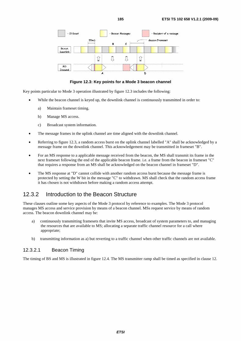
ETSI
ETSI TS 102 658 V1.2.1 (2009-09)185
A D
Beacon
Downlink
MS
Inbound
B C
55mS
- Beacon Messages- SYScast
Beacon Frameset
- Recipient of a message
Figure 12.3: Key points for a Mode 3 beacon channel
Key points particular to Mode 3 operation illustrated by figure 12.3 includes the following:
• While the beacon channel is keyed up, the downlink channel is continuously transmitted in order to:
a) Maintain frameset timing.
b) Manage MS access.
c) Broadcast system information.
• The message frames in the uplink channel are time aligned with the downlink channel.
• Referring to figure 12.3, a random access burst on the uplink channel labelled "A" shall be acknowledged by a message frame on the downlink channel. This acknowledgement may be transmitted in frameset "B".
• For an MS response to a applicable message received from the beacon, the MS shall transmit its frame in the next frameset following the end of the applicable beacon frame. i.e. a frame from the beacon in frameset "C" that requires a response from an MS shall be acknowledged on the beacon channel in frameset "D".
• The MS response at "D" cannot collide with another random access burst because the message frame is protected by setting the W bit in the message "C" to withdrawn. MS shall check that the random access frame it has chosen is not withdrawn before making a random access attempt.
12.3.2 Introduction to the Beacon Structure
These clauses outline some key aspects of the Mode 3 protocol by reference to examples. The Mode 3 protocol manages MS access and service provision by means of a beacon channel. MSs request service by means of random access. The beacon downlink channel may be:
a) continuously transmitting framesets that invite MS access, broadcast of system parameters to, and managing the resources that are available to MS; allocating a separate traffic channel resource for a call where appropriate;
b) transmitting information as a) but reverting to a traffic channel when other traffic channels are not available.
12.3.2.1 Beacon Timing
The timing of BS and MS is illustrated in figure 12.4. The MS transmitter ramp shall be timed as specified in clause 12.

ETSI
ETSI TS 102 658 V1.2.1 (2009-09)186
T x ra mp
3 0mS
T x ra mp
3 0 mS
72
PMS # 1
MS # 2
48 120 24 120
H I1H I0FS1 si
220mS
BS
120 24 12048
FS 1 MI1MI0 c c
72
P
120 24 12048
FS 1 MI1MI0 c c
48 120 24 120
H I1H I0FS1 si
55mS
120 24 120
CC
264 (55mS)
SY C1
264 (55mS)
48
FS 1
216
72 72 72
SY C2 SY C3 MI1MI0 c c
120 24 120
264 (55mS)
SY C1
264 (55mS)
48
FS 1
216
72 72 72
SY C2 SY C3 MI1MI0 c c
120 24 12048
FS 1 MI1MI0 c c
F ra meset
SY Scas t SY ScastB eacon Message B eacon M essageB eacon Message
Figure 12.4: Beacon Timing
Beacon messages and SYScast messages are transmitted alternately. MS transmissions are time aligned. The MS times its transmissions so that its bit 1 of its FS1 sync line up with bit 1 of FS1 from the Beacon downlink channel. Two MS transmissions (from MS #1 and MS #2) are illustrated. The timing constraints ensure that MS transmissions in adjacent framesets do not overlap.
SYScast messages are transmitted by the BS to broadcast information about the system to which MS are listening. If there are more bits to send than may be contained within a beacon message, SYScast frames may be displaced by data frames that are appended to a message frame to provide the additional bits.
12.3.3 Network architecture
12.3.3.1 Network functions
In addition to the normal call handling functions required to provide the telecommunication services identified above, a number of standard network procedures are needed for the efficient operation of the system and to provide an acceptable grade of service to the users.
12.3.3.1.1 Establishing service
A notable feature of a Mode 3 system is that physical channel acquisition is performed automatically when an MS is powered up. The user does not need to manually select physical channels. The relevant physical channel is stored in the MS or a search is performed to find an applicable Mode 3 beacon. If the MS is directed to a traffic channel, the applicable traffic channel is transmitted to the MS by a GoTo Channel frame that specifies the physical channel.
12.3.3.1.2 Network Identifier
All Mode 3 beacons carry a network and radio site identifier. This identifier, the System Identity Code (SYScode) is transmitted frequently by the beacon in the SYScast1 frame. The SYScode is composed of MODEL, NET and SITE information. Within a particular network, the NET remains a constant. Within a particular radio network, each beacon station is designated a different SITE parameter. MSs use the NET to determine if they are authorized to attempt to become active on that network.
12.3.3.2 MS Location by Registration
The coverage area of a Mode 3 network is divided into a number of Location Areas (dPMRLAs). A dPMRLA corresponds to a single radio site or a small number of radio sites structured as dPMRLAs.
Implicit registration is the network functionality that registers the location of the MS without need for an explicit registration frame. Implicit registration can be attained by any uplink beacon frame that conveys the MS individual identity, e.g. call request, service answer response.

ETSI
ETSI TS 102 658 V1.2.1 (2009-09)187
It is possible that due to adverse conditions the registration information held by the network and that held by the MS may not be the same. To restore and maintain the registration records:
a) The system shall update its registration records from MS random access call requests (The network may however deny the service requested by the MS for other reasons).
b) Responses from MS (resulting from a radio check for example) implicitly update the system registration records.
12.3.4 Trunking methods
Mode 3 systems implement the "message trunking" method.
Message trunking is a traffic (beacon/payload) channel allocation strategy in which the traffic channel is continuously allocated for the whole duration of a call, which may include several separate call items or transactions (i.e. PTT activation by separate terminals). The traffic channel is only de-allocated when the call is explicitly cleared by the call owner in the case of a group call, either party hanging up during an individual call or if a traffic channel inactivity timer expires. The BS may also clear the call at any time but the BS shall be confident that all parties in the call are able to hear the particular frame that clears down the call.
When a traffic channel has been allocated the users will experience the minimum delay for each transmission item since there is no queuing for the allocation of channel resources. The absence of any perceptible delay when the PTT is activated ensures that a conversation can proceed without interruption. This strategy is likely to minimize the processing and signalling overheads in the network infrastructure.
12.3.5 Beacon Channel Formats
A beacon shall employ one physical channel.
When idle, MSs shall listen to the beacon downlink channel.
Signalling on the beacon downlink channel is nominally continuous.
55mS
Beacon Frameset
Power-Save-Frameset = 8 x Beacon framesets =880mS
Beacon Frameset
Beacon
Outbound
Beacon Frame SYScast Frame
Figure 12.5: Beacon frames and Framesets
Figure 12.5 illustrates Beacon Frames, Beacon Framesets and Power-Save-Framesets.
A Beacon Frameset encompasses a SYScast Frame followed by a Beacon Frame.
A power_save-frame is defined by transmission of 8 consecutive Beacon Framesets. A power_save frame is transmitted by a Beacon every 880 ms. Power save is described in clause 12.3.10.
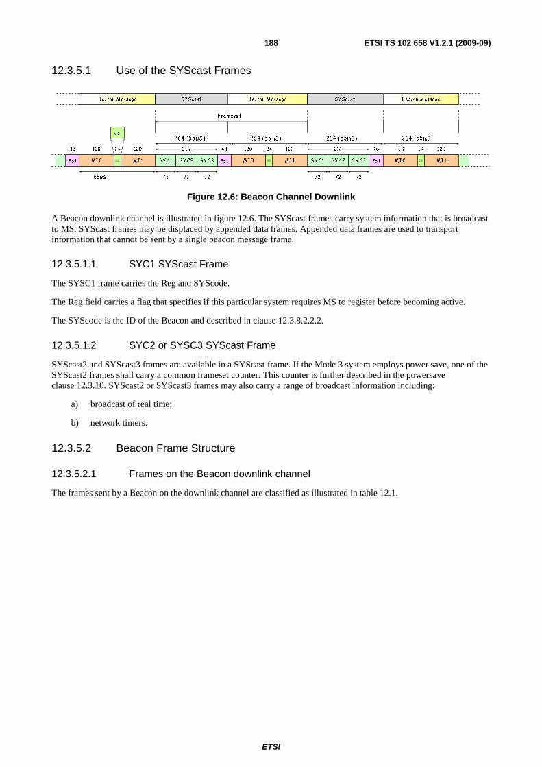
ETSI
ETSI TS 102 658 V1.2.1 (2009-09)188
12.3.5.1 Use of the SYScast Frames
55mS
120 24 120
CC
26 4 (55 mS )
S Y C1
26 4 (55 mS )
48
FS 1
216
72 72 72
S Y C 2 S Y C 3
F ra meset
M I1M I0 c c
120 24 120
26 4 (55 mS )
S Y C1
26 4 (55 mS )
48
FS 1
216
72 72 72
S Y C 2 S Y C 3 M I1M I0 c c
SY Scast SY Scas tB eacon M ess age B eacon M es s ageB eacon M ess age
120 24 12048
FS 1 M I1M I0 c c
Figure 12.6: Beacon Channel Downlink
A Beacon downlink channel is illustrated in figure 12.6. The SYScast frames carry system information that is broadcast to MS. SYScast frames may be displaced by appended data frames. Appended data frames are used to transport information that cannot be sent by a single beacon message frame.
12.3.5.1.1 SYC1 SYScast Frame
The SYSC1 frame carries the Reg and SYScode.
The Reg field carries a flag that specifies if this particular system requires MS to register before becoming active.
The SYScode is the ID of the Beacon and described in clause 12.3.8.2.2.2.
12.3.5.1.2 SYC2 or SYSC3 SYScast Frame
SYScast2 and SYScast3 frames are available in a SYScast frame. If the Mode 3 system employs power save, one of the SYScast2 frames shall carry a common frameset counter. This counter is further described in the powersave clause 12.3.10. SYScast2 or SYScast3 frames may also carry a range of broadcast information including:
a) broadcast of real time;
b) network timers.
12.3.5.2 Beacon Frame Structure
12.3.5.2.1 Frames on the Beacon downlink channel
The frames sent by a Beacon on the downlink channel are classified as illustrated in table 12.1.
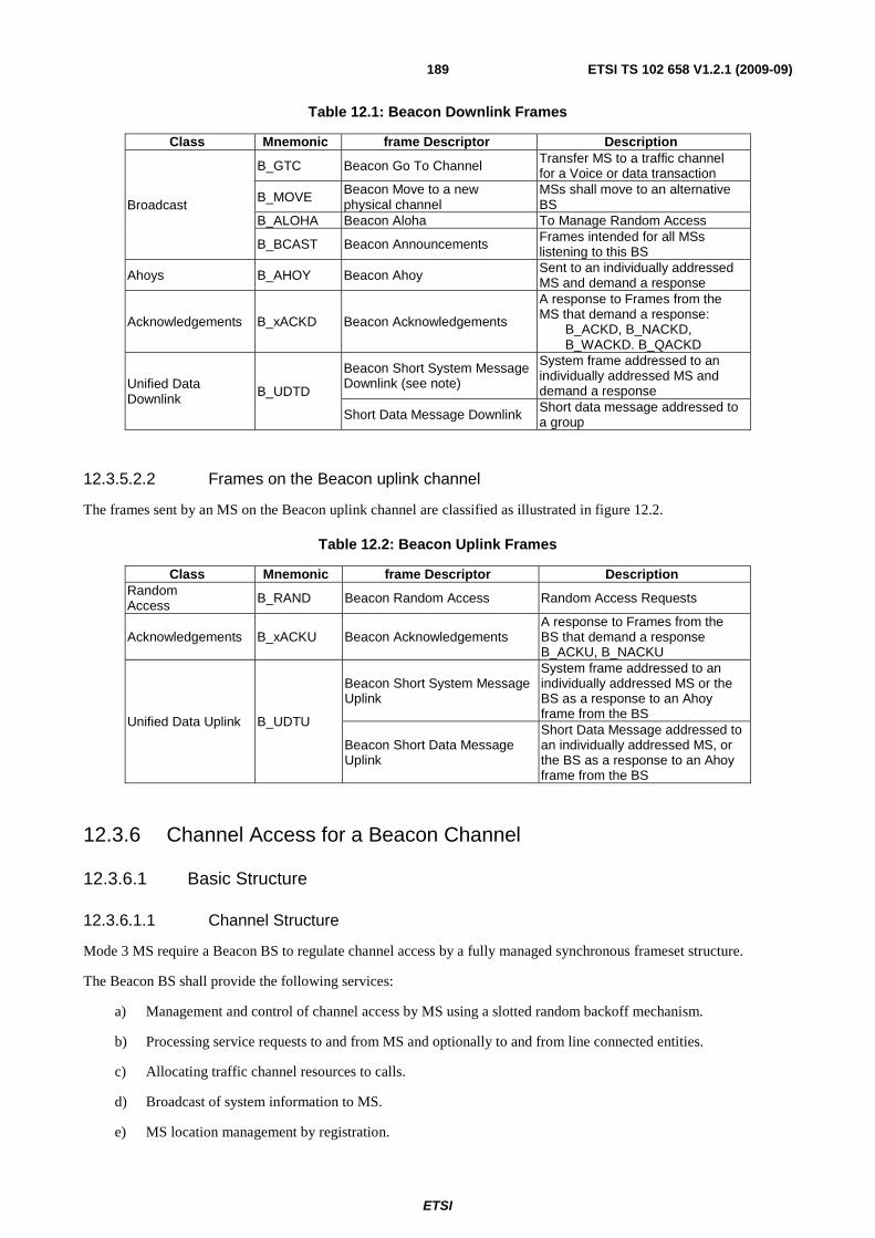
ETSI
ETSI TS 102 658 V1.2.1 (2009-09)189
Table 12.1: Beacon Downlink Frames
Class Mnemonic frame Descriptor Description
Broadcast
B_GTC Beacon Go To Channel Transfer MS to a traffic channel for a Voice or data transaction
B_MOVE Beacon Move to a new physical channel
MSs shall move to an alternative BS
B_ALOHA Beacon Aloha To Manage Random Access
B_BCAST Beacon Announcements Frames intended for all MSs listening to this BS
Ahoys B_AHOY Beacon Ahoy Sent to an individually addressed MS and demand a response
Acknowledgements B_xACKD Beacon Acknowledgements
A response to Frames from the MS that demand a response: B_ACKD, B_NACKD,
B_WACKD. B_QACKD
Unified Data Downlink B_UDTD
Beacon Short System Message Downlink (see note)
System frame addressed to an individually addressed MS and demand a response
Short Data Message Downlink Short data message addressed to a group
12.3.5.2.2 Frames on the Beacon uplink channel
The frames sent by an MS on the Beacon uplink channel are classified as illustrated in figure 12.2.
Table 12.2: Beacon Uplink Frames
Class Mnemonic frame Descriptor Description Random Access B_RAND Beacon Random Access Random Access Requests
Acknowledgements B_xACKU Beacon Acknowledgements A response to Frames from the BS that demand a response B_ACKU, B_NACKU
Unified Data Uplink B_UDTU
Beacon Short System Message Uplink
System frame addressed to an individually addressed MS or the BS as a response to an Ahoy frame from the BS
Beacon Short Data Message Uplink
Short Data Message addressed to an individually addressed MS, or the BS as a response to an Ahoy frame from the BS
12.3.6 Channel Access for a Beacon Channel
12.3.6.1 Basic Structure
12.3.6.1.1 Channel Structure
Mode 3 MS require a Beacon BS to regulate channel access by a fully managed synchronous frameset structure.
The Beacon BS shall provide the following services:
a) Management and control of channel access by MS using a slotted random backoff mechanism.
b) Processing service requests to and from MS and optionally to and from line connected entities.
c) Allocating traffic channel resources to calls.
d) Broadcast of system information to MS.
e) MS location management by registration.

ETSI
ETSI TS 102 658 V1.2.1 (2009-09)190
f) Provision of complementary services such as beacon short data polling and transfer.
g) Beacon power save.
12.3.6.1.2 Physical Channel Addressing
The Mode 3 protocol supports a number of different physical channel strategies to accommodate operation in physical radio channels that may be dedicated, in blocks or allocated on an ad-hoc basis by an external agency. Physical radio channels are specified by a mechanism whereby the absolute transmitter and receiver frequencies are specified in the fields of frames that are passed between dPMR entities at the air interface.
12.3.6.1.3 Sub-Division of the MS population
Certain messages transmitted by the BS may be directed to and applicable only to a sub-set of the MS population. Examples are Aloha (B_ALOHA) Frames and Broadcast (B_BCAST) Frames. Applicable Frames contain a 24 bit address fields and a 5 bit (Mask) number field. The sub-set division is achieved by using the address qualifier (Mask) from the frame. This parameter instructs an MS to compare the "Mask" least significant bits of its individual address with the "Mask" least significant bits of the address field from the frame (containing the MASK) to determine if that frame is applicable.
An MS shall note the population subdivision contained in each applicable frame that it receives. For Mask = 0 to 24, the frame is applicable to the unit if the "Mask" least significant bits of the Aloha address match the "Mask" least significant bits of its individual address.
In this way, the MS population is effectively divided into 2Masksubsets:
• If Mask = 0 then no address bits are compared, so there is no subdivision.
• If Mask = 1 then only MS whose least significant individual address bit matches the least significant individual address bit from the frame received shall consider the frame to be applicable to that particular MS.
This process continues up to Mask = 24. In this case the frame is only applicable to one MS.
Beacon Outbound
Individual Address
0000 0000 0010 1010 0001 10012
Applicable Message
Address Mask
24 bits 5 bits
0 0 1 0 1 0 1 0 0 0 0 0 1 0 0 10 0 0 0 0 0 0 0
0 0 1 0 1 0 1 0 0 0 0 1 1 0 0 10 0 0 0 0 0 0 0
MS
Figure 12.7: Example of frame containing the "Mask" field
Figure 12.7 illustrates an MS personalized with the address 0000 0000 0010 1010 0001 10012.
A frame is received that contains a Mask field. The MS shall therefore determine if that frame is applicable or the frame shall be discarded.
EXAMPLE 1: The Mask field contains the value 0 01002.
The value of the Mask is 4 therefore the MS compares the 4 least significant bits of the address field in the frame received with the 4 least significant bits of the MS individual address.
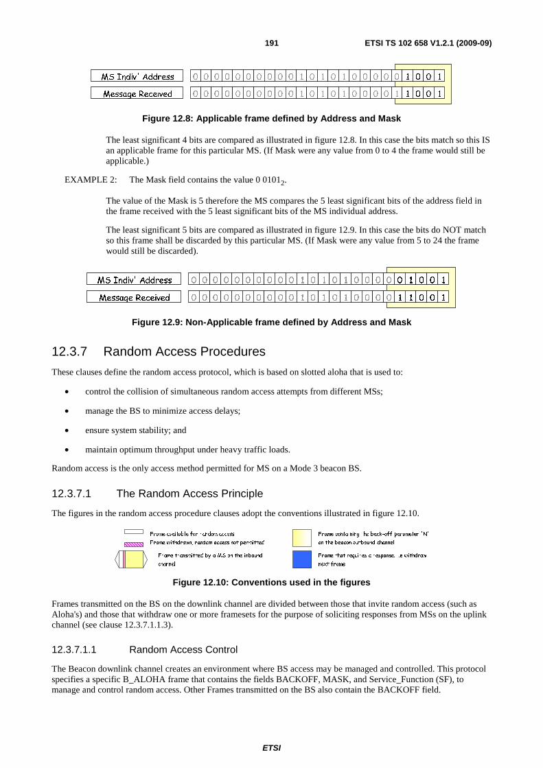
ETSI
ETSI TS 102 658 V1.2.1 (2009-09)191
0 0 1 0 1 0 1 0 0 0 0 1 1 0 0 10 0 0 0 0 0 0 0
0 0 1 0 1 0 1 0 0 0 0 0 1 0 0 10 0 0 0 0 0 0 0
Message Received
MS Indiv' Address
Figure 12.8: Applicable frame defined by Address and Mask
The least significant 4 bits are compared as illustrated in figure 12.8. In this case the bits match so this IS an applicable frame for this particular MS. (If Mask were any value from 0 to 4 the frame would still be applicable.)
EXAMPLE 2: The Mask field contains the value 0 01012.
The value of the Mask is 5 therefore the MS compares the 5 least significant bits of the address field in the frame received with the 5 least significant bits of the MS individual address.
The least significant 5 bits are compared as illustrated in figure 12.9. In this case the bits do NOT match so this frame shall be discarded by this particular MS. (If Mask were any value from 5 to 24 the frame would still be discarded).
0 0 1 0 1 0 1 0 0 0 0 1 1 0 0 10 0 0 0 0 0 0 0
0 0 1 0 1 0 1 0 0 0 0 0 1 0 0 10 0 0 0 0 0 0 0
Message Received
MS Indiv' Address
Figure 12.9: Non-Applicable frame defined by Address and Mask
12.3.7 Random Access Procedures
These clauses define the random access protocol, which is based on slotted aloha that is used to:
• control the collision of simultaneous random access attempts from different MSs;
• manage the BS to minimize access delays;
• ensure system stability; and
• maintain optimum throughput under heavy traffic loads.
Random access is the only access method permitted for MS on a Mode 3 beacon BS.
12.3.7.1 The Random Access Principle
The figures in the random access procedure clauses adopt the conventions illustrated in figure 12.10.
Frame containing the back-off parameter 'N'
on the beacon outbound channel
Frame that requires a response. i.e withdraw
next frame
Frame withdrawn, random access not permitted
Frame available for random access
Frame transmitted by a MS on the inbound
channel
Figure 12.10: Conventions used in the figures
Frames transmitted on the BS on the downlink channel are divided between those that invite random access (such as Aloha's) and those that withdraw one or more framesets for the purpose of soliciting responses from MSs on the uplink channel (see clause 12.3.7.1.1.3).
12.3.7.1.1 Random Access Control
The Beacon downlink channel creates an environment where BS access may be managed and controlled. This protocol specifies a specific B_ALOHA frame that contains the fields BACKOFF, MASK, and Service_Function (SF), to manage and control random access. Other Frames transmitted on the BS also contain the BACKOFF field.
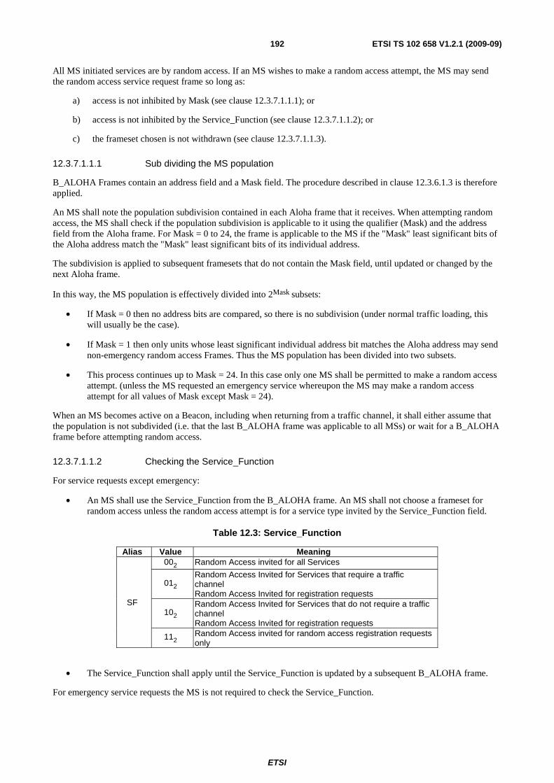
ETSI
ETSI TS 102 658 V1.2.1 (2009-09)192
All MS initiated services are by random access. If an MS wishes to make a random access attempt, the MS may send the random access service request frame so long as:
a) access is not inhibited by Mask (see clause 12.3.7.1.1.1); or
b) access is not inhibited by the Service_Function (see clause 12.3.7.1.1.2); or
c) the frameset chosen is not withdrawn (see clause 12.3.7.1.1.3).
12.3.7.1.1.1 Sub dividing the MS population
B_ALOHA Frames contain an address field and a Mask field. The procedure described in clause 12.3.6.1.3 is therefore applied.
An MS shall note the population subdivision contained in each Aloha frame that it receives. When attempting random access, the MS shall check if the population subdivision is applicable to it using the qualifier (Mask) and the address field from the Aloha frame. For Mask = 0 to 24, the frame is applicable to the MS if the "Mask" least significant bits of the Aloha address match the "Mask" least significant bits of its individual address.
The subdivision is applied to subsequent framesets that do not contain the Mask field, until updated or changed by the next Aloha frame.
In this way, the MS population is effectively divided into 2Mask subsets:
• If Mask = 0 then no address bits are compared, so there is no subdivision (under normal traffic loading, this will usually be the case).
• If Mask = 1 then only units whose least significant individual address bit matches the Aloha address may send non-emergency random access Frames. Thus the MS population has been divided into two subsets.
• This process continues up to Mask = 24. In this case only one MS shall be permitted to make a random access attempt. (unless the MS requested an emergency service whereupon the MS may make a random access attempt for all values of Mask except Mask = 24).
When an MS becomes active on a Beacon, including when returning from a traffic channel, it shall either assume that the population is not subdivided (i.e. that the last B_ALOHA frame was applicable to all MSs) or wait for a B_ALOHA frame before attempting random access.
12.3.7.1.1.2 Checking the Service_Function
For service requests except emergency:
• An MS shall use the Service_Function from the B_ALOHA frame. An MS shall not choose a frameset for random access unless the random access attempt is for a service type invited by the Service_Function field.
Table 12.3: Service_Function
Alias Value Meaning
SF
002 Random Access invited for all Services
012 Random Access Invited for Services that require a traffic channel Random Access Invited for registration requests
102 Random Access Invited for Services that do not require a traffic channel Random Access Invited for registration requests
112 Random Access invited for random access registration requests only
• The Service_Function shall apply until the Service_Function is updated by a subsequent B_ALOHA frame.
For emergency service requests the MS is not required to check the Service_Function.
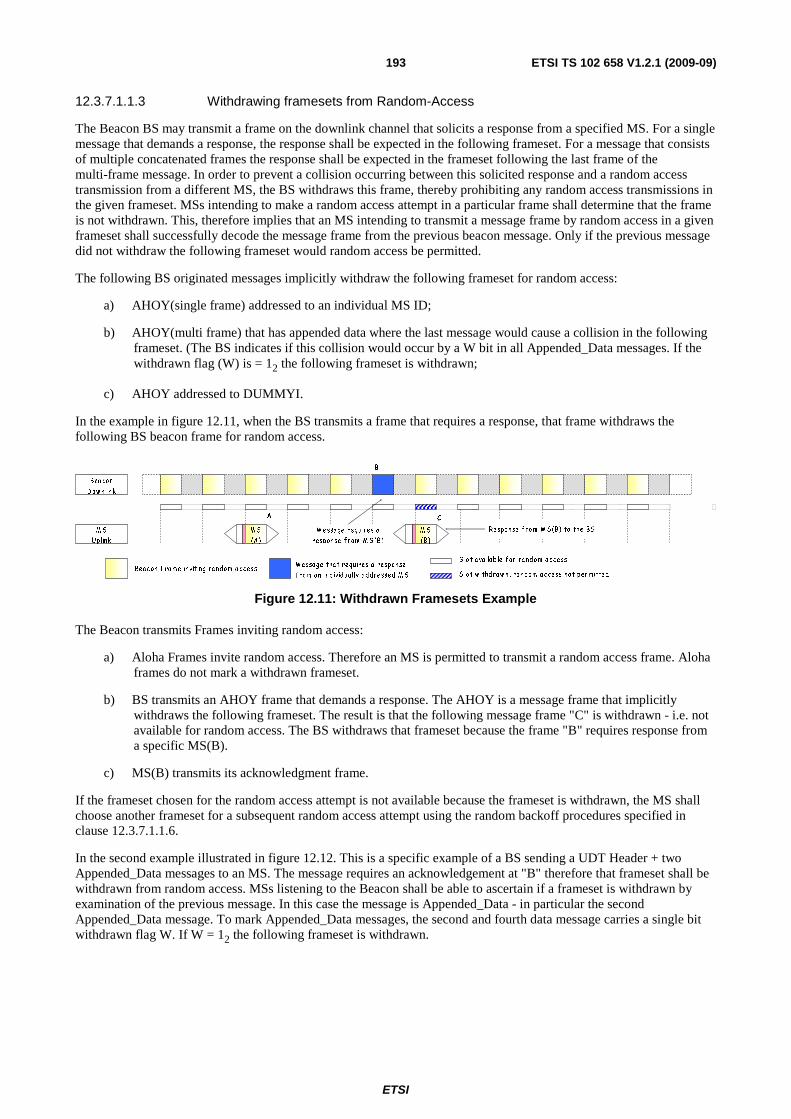
ETSI
ETSI TS 102 658 V1.2.1 (2009-09)193
12.3.7.1.1.3 Withdrawing framesets from Random-Access
The Beacon BS may transmit a frame on the downlink channel that solicits a response from a specified MS. For a single message that demands a response, the response shall be expected in the following frameset. For a message that consists of multiple concatenated frames the response shall be expected in the frameset following the last frame of the multi-frame message. In order to prevent a collision occurring between this solicited response and a random access transmission from a different MS, the BS withdraws this frame, thereby prohibiting any random access transmissions in the given frameset. MSs intending to make a random access attempt in a particular frame shall determine that the frame is not withdrawn. This, therefore implies that an MS intending to transmit a message frame by random access in a given frameset shall successfully decode the message frame from the previous beacon message. Only if the previous message did not withdraw the following frameset would random access be permitted.
The following BS originated messages implicitly withdraw the following frameset for random access:
a) AHOY(single frame) addressed to an individual MS ID;
b) AHOY(multi frame) that has appended data where the last message would cause a collision in the following frameset. (The BS indicates if this collision would occur by a W bit in all Appended_Data messages. If the withdrawn flag (W) is = 12 the following frameset is withdrawn;
c) AHOY addressed to DUMMYI.
In the example in figure 12.11, when the BS transmits a frame that requires a response, that frame withdraws the following BS beacon frame for random access.
Bea con
D ow n link
M S
U plink
B
S lot w ithd ra w n , ra ndom a ccess not perm ittedM essa ge that requ ires a response
from a n ind ividua lly a ddressed M SBea con F ra m e inviting ra ndom a ccess
S lot a va ila b le f or ra ndom access
M essa ge requires a
response f rom M S (B)
Response f rom M S (B) to the BS
CA
M S
(A)
M S
(B )
Figure 12.11: Withdrawn Framesets Example
The Beacon transmits Frames inviting random access:
a) Aloha Frames invite random access. Therefore an MS is permitted to transmit a random access frame. Aloha frames do not mark a withdrawn frameset.
b) BS transmits an AHOY frame that demands a response. The AHOY is a message frame that implicitly withdraws the following frameset. The result is that the following message frame "C" is withdrawn - i.e. not available for random access. The BS withdraws that frameset because the frame "B" requires response from a specific MS(B).
c) MS(B) transmits its acknowledgment frame.
If the frameset chosen for the random access attempt is not available because the frameset is withdrawn, the MS shall choose another frameset for a subsequent random access attempt using the random backoff procedures specified in clause 12.3.7.1.1.6.
In the second example illustrated in figure 12.12. This is a specific example of a BS sending a UDT Header + two Appended_Data messages to an MS. The message requires an acknowledgement at "B" therefore that frameset shall be withdrawn from random access. MSs listening to the Beacon shall be able to ascertain if a frameset is withdrawn by examination of the previous message. In this case the message is Appended_Data - in particular the second Appended_Data message. To mark Appended_Data messages, the second and fourth data message carries a single bit withdrawn flag W. If W = 12 the following frameset is withdrawn.
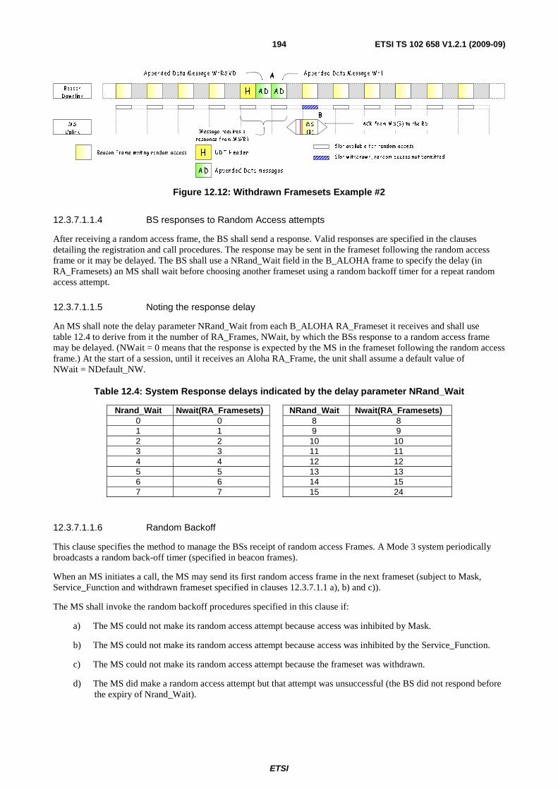
ETSI
ETSI TS 102 658 V1.2.1 (2009-09)194
Beac on
D ow nlink
M S
U plink
S lot w ithdraw n, ra ndom a c cess not perm ittedUD T H ea d erBea con F ra m e inviting ra ndom a cc ess
S lot ava ilab le f or random ac c ess
M essage requires a
response f rom M S(B )
ACK f rom M S (B) to the BS
B
A
AD AD
H
AD
H
A ppend ed D ata m essa ges
A ppend ed D ata M essage W =RS V D A ppend ed D a ta M essage W =1
M S
(B)
Figure 12.12: Withdrawn Framesets Example #2
12.3.7.1.1.4 BS responses to Random Access attempts
After receiving a random access frame, the BS shall send a response. Valid responses are specified in the clauses detailing the registration and call procedures. The response may be sent in the frameset following the random access frame or it may be delayed. The BS shall use a NRand_Wait field in the B_ALOHA frame to specify the delay (in RA_Framesets) an MS shall wait before choosing another frameset using a random backoff timer for a repeat random access attempt.
12.3.7.1.1.5 Noting the response delay
An MS shall note the delay parameter NRand_Wait from each B_ALOHA RA_Frameset it receives and shall use table 12.4 to derive from it the number of RA_Frames, NWait, by which the BSs response to a random access frame may be delayed. (NWait = 0 means that the response is expected by the MS in the frameset following the random access frame.) At the start of a session, until it receives an Aloha RA_Frame, the unit shall assume a default value of NWait = NDefault_NW.
Table 12.4: System Response delays indicated by the delay parameter NRand_Wait
Nrand_Wait Nwait(RA_Framesets) NRand_Wait Nwait(RA_Framesets) 0 0 8 8 1 1 9 9 2 2 10 10 3 3 11 11 4 4 12 12 5 5 13 13 6 6 14 15 7 7 15 24
12.3.7.1.1.6 Random Backoff
This clause specifies the method to manage the BSs receipt of random access Frames. A Mode 3 system periodically broadcasts a random back-off timer (specified in beacon frames).
When an MS initiates a call, the MS may send its first random access frame in the next frameset (subject to Mask, Service_Function and withdrawn frameset specified in clauses 12.3.7.1.1 a), b) and c)).
The MS shall invoke the random backoff procedures specified in this clause if:
a) The MS could not make its random access attempt because access was inhibited by Mask.
b) The MS could not make its random access attempt because access was inhibited by the Service_Function.
c) The MS could not make its random access attempt because the frameset was withdrawn.
d) The MS did make a random access attempt but that attempt was unsuccessful (the BS did not respond before the expiry of Nrand_Wait).

ETSI
ETSI TS 102 658 V1.2.1 (2009-09)195
If the MS makes a random access attempt and is unsuccessful, the MS shall choose a frameset for its next random access attempt by choosing a random number between the limits of one and the BACKOFF parameter using a statistically uniform distribution.
Figure 12.13 illustrates a BS using parameters NRand_Wait=0. The most recent value of BACKOFF received=4.
Expected Beacon response w indow for N rand_ W ait=0
A
Beacon
D ow n link
M S
U plink
B 1 2 3 4
R
Figure 12.13: Random Backoff Example #1
a) At "A" the MS makes a random access attempt. NRand_Wait=0 indicates that the BS shall respond in the next frameset at "B".
b) After frameset "B" a response has not been received, therefore the MS chooses one of the framesets 1, 2, 3, 4 randomly for its next access attempt.
Figure 12.14 illustrates a BS using parameters NRand_Wait=1. The most recent value of back-off received=4.
Beacon
D ow nlink
M S
Uplink
B 1 2 3 4
Expected TS CC response w indow for N rand_W ait=1
A
R
Figure 12.14: Random backoff Example #2
a) The MS makes a random access attempt. NRand_Wait=1 indicates that the BS shall respond in one of the next two framesets at "B".
b) After frameset "B" a response has not been received, therefore the MS chooses one of the framesets 1, 2, 3, 4 randomly for its next access attempt.
A number of downlink channel Frames including an Aloha frame contain the BACKOFF field.
The BACKOFF may be altered by the BS and broadcast to MS to respond to varying load conditions presented to the system throughout the course of operation. If the system has a light traffic load, the BACKOFF may be small, so decreasing random access latency. If the traffic load increases a longer backoff may be warranted to spread competing of random access attempts from different MSs by the BS transmitting a larger backoff number. This traffic load may be estimated from historical usage or may be calculated from the burst traffic being received at that time.
The BACKOFF parameter may change while the MS is already making random access attempts. When the MS has chosen a random frameset, that frameset shall be preserved for the duration of the current random access attempt. Any new value of backoff parameter from the BS shall be noted by the MS and shall be employed if the MS needs to choose a new random frameset for its next random access attempt.
For Frames that contain the BACKOFF field, the number of backoff RA_Framesets is coded, so that more backoff RA_Framesets can be realized than a pure binary representation would permit. The explicit numbers of RA_Framesets resulting from the back-off number is indicated by table 12.5.

ETSI
ETSI TS 102 658 V1.2.1 (2009-09)196
Table 12.5: Number of backoff framesets indicated by the Backoff Number
Backoff Number Back-off Framesets Backoff Number Back-off Framesets 0 Reserved 8 15 1 1 9 20 2 2 10 26 3 3 11 33 4 4 12 41 5 5 13 50 6 8 14 70 7 11 15 100
Note that:
a) A B_ALOHA frame with M=24 invites access only for one specific individual MS;
b) In the example in figure 12.11, if an MS had chosen the frameset "C" for a random access attempt, that MS would be able to determine that the frameset was not available for random access because the frameset was withdrawn by decoding the W bit from the previous beacon message and noting that the frameset the MS had chosen was withdrawn. The MS would abandon that random access attempt, and choose another candidate frameset using the random backoff parameter;
c) The MS shall rely on the W bit to determine if the following random-access frameset is withdrawn. If the MS does not successfully receive the preceding beacon message, the MS shall assume the frameset is withdrawn and abandon that particular random access attempt.
12.3.7.1.1.8 Retry decision and time-outs
After sending a random access frame, an MS shall wait to receive a response from the BS. Various frames shall be accepted as a valid response (as specified in the clauses detailing the registration and call procedures).
The MS shall abandon its access attempt if it has sent the maximum permitted number of random access for the particular service requested and received no valid response. This number depends on the service and priority of service being requested:
• For non-emergency random access requests, it is NRand_NR.
• For emergency random access requests, it is NRand_NE.
The MS shall also operate a time-out TRand_TC that defines the maximum time it waits trying to achieve random access, and abandon the attempt if this time-out expires.
If the unit's access attempt fails as a result of TRand_TC timeout then:
a) if the MS has not transmitted a frame, it shall return to the idle state (and may indicate the failure to the user);
b) otherwise, (the MS has made at least one random access attempt) if the TRand_TC timer expires while the MS is waiting Nwait+1 for the last random access attempt, the MS shall complete the Nwait+1 RA_Frames before abandoning its random access.
12.3.7.1.2 Action after receiving an acknowledgement
The MS shall not re-transmit any further random access frame when an appropriate acknowledgement has been received from the BS. Various Frames that are acceptable in addition to specific acknowledgement Frames are indicated in the procedures specified in the present document. An applicable BS response to a random access request shall start an MS timer. This timer may be restarted by the reception of a further applicable acknowledgement frame from the BS. Two values are specified for this timer. One value TP_Timer shall be used if the random access service requires a traffic channel (for example a speech or data service). The second value TNP_Timer shall be used for services that only make use of the BS resource (for example Registration, Short Data service).
ETSI
ETSI TS 102 658 V1.2.1 (2009-09)197
12.3.7.1.3 MS Arriving on a Beacon Channel
Channel access regulation for trunked systems is implemented by a BS transmitting signalling on the downlink channel with periodic Frames that define regulated channel access.
When an MS tunes to a new channel where the recent history of channel activity is unknown, the MS shall establish that the BS is identified as one that the MS is permitted to access.
a) The MS shall wait until it receives a Colour Code field. The MS shall check that this particular channel is transmitting a Colour Code that is expected by the MS; and
b) The MS shall wait until it explicitly receives the SYScode being transmitted on the BS. If the MS is authorized to access this BS, the MS shall wait for an applicable B_ALOHA frame before it attempts access by random access procedures defined in these clauses.
12.3.8 Beacon Channel Acquisition and Retention
Unless assigned to a traffic channel (including immediately after switch-on), the MS shall attempt to find a BS beacon appropriate to the MSs selected network. The search for a BS may be performed by a general hunt through all likely channels or by reference to parameters stored within the MS. A framework for MS hunting is described in annex B.
An MS shall not make any transmissions on a beacon BS unless it is active on that channel. It shall not become active until it has received a SYScode that authorizes the MS to access that BS.
If an MS is hunting over a number of candidate channels, it shall leave the selected channel as soon as it becomes evident that the MS shall not be permitted service.
The discipline for MSs whilst active a BS and the circumstances which may result in a search for a new BS are the subjects of clause 12.3.8.2.
In particular:
• the method by which the MS searches for an appropriate BS;
• the criteria to which a BS shall be considered appropriate by the MS - authorization;
• procedures for returning to the BS acquisition procedures.
The methods specified in this clause recognize that designers of networks may choose from a variety of beacon channel.
The beacon channel acquisition and retention procedures specified in the present document may result in the MS encountering a variety of beacon channel situations, including:
a) receiving a BS which suffers short-term interruptions (radio fading and multi-path reception);
b) suffering long-term interruptions to BS reception during which no appropriate BS can be received by the MS (moving out of range of the network);
c) being in a location where it is possible for more than one BS to be received from the selected network, involving the unit in a choice;
d) being instructed to leave a BS;
e) being instructed to leave or being barred from access to, a BS as a result of a network load sharing arrangement;
f) Being instructed to sample an alternative BS on an adjacent radio site (Vote Now).
Procedures have been specified in the present document to indicate to MS when they may sample an adjacent radio site for a BS that may provide an improved grade of service for the MS user. This is achieved on the BS transmitting a frame that invites all MS to leave the BS momentarily. During this sample time the BS can discontinue call transactions. Notwithstanding this, manufacturers may devise their own procedures that will allow an MS to leave the current BS to sample for an alternative BS. However it shall be noted that if the MS leaves the BS on its own volition the MS may miss a BS transaction specifically addressed to that MS.
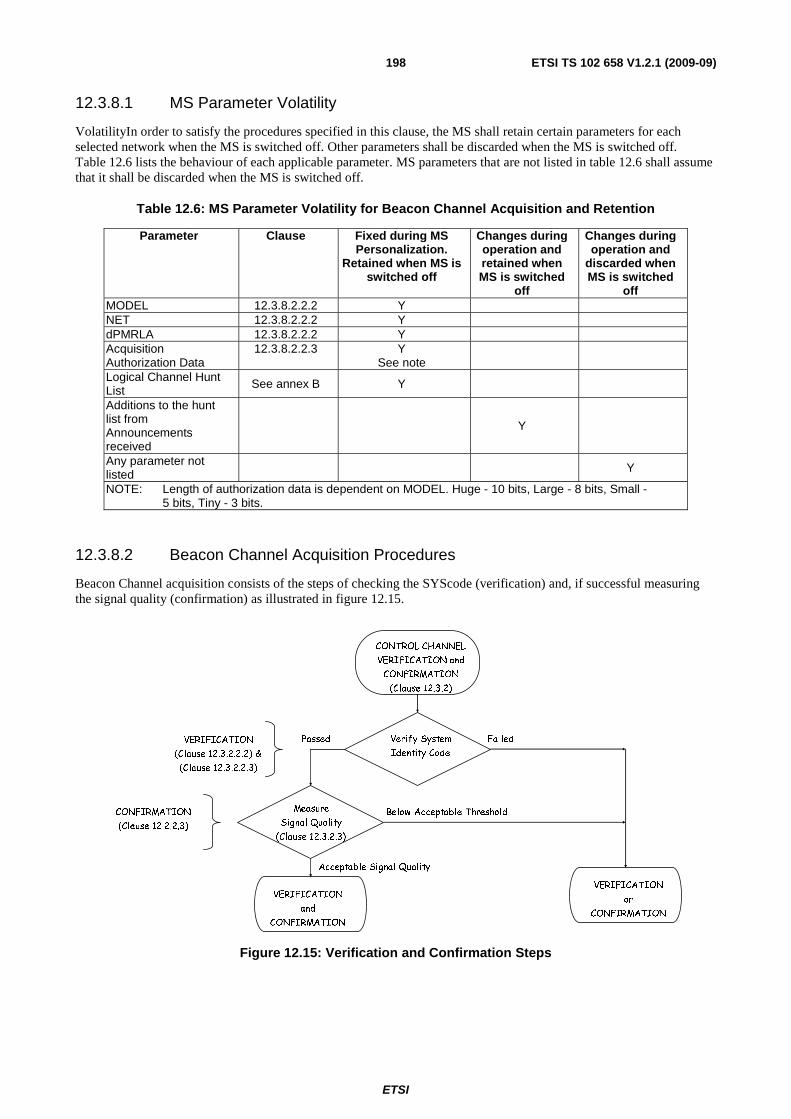
ETSI
ETSI TS 102 658 V1.2.1 (2009-09)198
12.3.8.1 MS Parameter Volatility
VolatilityIn order to satisfy the procedures specified in this clause, the MS shall retain certain parameters for each selected network when the MS is switched off. Other parameters shall be discarded when the MS is switched off. Table 12.6 lists the behaviour of each applicable parameter. MS parameters that are not listed in table 12.6 shall assume that it shall be discarded when the MS is switched off.
Table 12.6: MS Parameter Volatility for Beacon Channel Acquisition and Retention
Parameter Clause Fixed during MS Personalization.
Retained when MS is switched off
Changes during operation and retained when MS is switched
off
Changes during operation and
discarded when MS is switched
off MODEL 12.3.8.2.2.2 Y NET 12.3.8.2.2.2 Y dPMRLA 12.3.8.2.2.2 Y Acquisition Authorization Data
12.3.8.2.2.3 Y See note
Logical Channel Hunt List See annex B Y
Additions to the hunt list from Announcements received
Y
Any parameter not listed
Y
NOTE: Length of authorization data is dependent on MODEL. Huge - 10 bits, Large - 8 bits, Small - 5 bits, Tiny - 3 bits.
12.3.8.2 Beacon Channel Acquisition Procedures
Beacon Channel acquisition consists of the steps of checking the SYScode (verification) and, if successful measuring the signal quality (confirmation) as illustrated in figure 12.15.
Passed Failed
Measure
Signal Quality
(Clause 12.3.2.3)
Below Acceptable Threshold
VERIFICATION
and
CONFIRMATION
Verify System
Identity Code
CONFIRMATION
(Clause 12.2.2.3)
VERIFICATION
(Clause 12.3.2.2.2) &
(Clause 12.3.2.2.3)
CONTROL CHANNEL
VERIFICATION and
CONFIRMATION
(Clause 12.3.2)
Acceptable Signal Quality
VERIFICATION
or
CONFIRMATION
Figure 12.15: Verification and Confirmation Steps

ETSI
ETSI TS 102 658 V1.2.1 (2009-09)199
12.3.8.2.1 Entry into Beacon Acquisition Procedures
The Beacon acquisition procedures enable an MS that is not assigned to a traffic channel to attempt to select a suitable BS. Beacon acquisition is a procedure that consists of hunting for candidate BSs and attempting to verify that the MS is authorized to become active on that selected BS.
The MS shall enter into the BS acquisition procedures under the following circumstances:
a) immediately after switch-on;
b) a user-initiated change of selected network;
c) when it has relinquished the current BS under the procedures specified in clause 12.3.8.3;
d) when it has received a T_CLEAR frame on a traffic channel;
e) when it has sent Disconnect_Request Header Frames or timed-out on a traffic channel;
f) when it has received a call T_AHOY(M=Cancel Call Service) frame on a traffic channel which requires it to vacate that channel.
At all times during the BS acquisition procedures the MS shall mute its received audio and transmission shall be inhibited.
A framework for BS beacon channel hunting is provided in annex B.
12.3.8.2.2 Identifying a Candidate Beacon Channel
When an MS is searching for a suitable beacon channel, the MS shall examine any signal detected for conformity with BS structure. The MS shall accept as a candidate BS any channel on which a BS FS1 synchronization sequence is detected.
The method by which the MS identifies candidate BSs during hunting is not detailed in the present document. In particular no maximum time allowance for this procedure is specified, although attention is drawn to the necessity of completing tests as quickly as possible, notably on channels which can be easily rejected as BS candidates (e.g. invalid parameters from the SYScode), since the overall speed of the hunt (and thus efficiency of service to the user) depends on the rapidity with which these tests can be carried out.
12.3.8.2.2.1 Checking the System Identity Code
When the MS has identified a candidate Beacon, it shall examine the values of the SYScode fields from the BS Frames that transmit the SYScode field and the Colour Code.
The time which the MS may continue to search for a value of SYScode field and frames that contain the Colour Code for verification is not specified since this depends on the regularity by which the BS transmits these parameters.
When the MS checked the Colour Code and has selected a SYScode field for verification, it shall decide if it is authorized to acquire the BS (see clause 12.3.8.2.2.3). If acquisition is permitted then the MS shall become active on that BS and start the signal quality checking procedures specified in clause 12.3.8.2.3.
Whilst active on a BS, after verification but prior to confirmation, the MS shall not transmit any random access frames, but it shall comply with any applicable frames received, as required, provided that to do so does not involve transmitting to the BS.
12.3.8.2.2.2 Structure of the System Identity Code (SYScode)
dPMR trunked networks may range from tiny systems consisting of a very small number of sites to very large systems covering a wide geographic area. To accommodate this wide range of networks, dPMR specifies four network Models, each with characteristics appropriate to each Model.
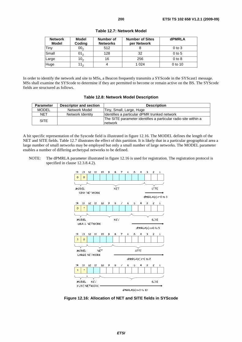
ETSI
ETSI TS 102 658 V1.2.1 (2009-09)200
Table 12.7: Network Model
Network Model
Model Coding
Number of Networks
Number of Sites per Network
dPMRLA
Tiny 002 512 8 0 to 3
Small 012 128 32 0 to 5
Large 102 16 256 0 to 8
Huge 112 4 1 024 0 to 10
In order to identify the network and site to MSs, a Beacon frequently transmits a SYScode in the SYScast1 message. MSs shall examine the SYScode to determine if they are permitted to become or remain active on the BS. The SYScode fields are structured as follows.
Table 12.8: Network Model Description
Parameter Descriptor and section Description MODEL Network Model Tiny, Small, Large, Huge
NET Network Identity Identifies a particular dPMR trunked network
SITE The SITE parameter identifies a particular radio site within a network
A bit specific representation of the Syscode field is illustrated in figure 12.16. The MODEL defines the length of the NET and SITE fields. Table 12.7 illustrates the effect of this partition. It is likely that in a particular geographical area a large number of small networks may be employed but only a small number of large networks. The MODEL parameter enables a number of differing archetypal networks to be defined.
NOTE: The dPMRLA parameter illustrated in figure 12.16 is used for registration. The registration protocol is specified in clause 12.3.8.4.2).
0 0
dPMRLA(n) n=0 to 3
12345678910111214 13
SITENETMODEL
TINY NETWORK
0 1
MODEL
dPMRLA(n) n=0 to 5
SITENET
SMALL NETWORK
12345678910111214 13
1 0
MODEL
dPMRLA(n) n=0 to 8
SITENET
LARGE NETWORK
12345678910111214 13
1 1
MODEL
dPMRLA(n) n=0 to 10
SITENET
HUGE NETWORK
12345678910111214 13
Figure 12.16: Allocation of NET and SITE fields in SYScode

ETSI
ETSI TS 102 658 V1.2.1 (2009-09)201
12.3.8.2.2.3 BS Authorization Procedure
The MS shall read the SYScode being transmitted by the beacon BS:
a) Checking the MODEL:
- The MS shall compare the MODEL transmitted in the SYScode on the BS with the MODEL stored in MS fixed non-volatile storage. If there is no match then the MS unit shall assume that it is not authorized to acquire the BS under test.
b) Checking the NET:
• If the MS has successfully verified a) above then:
- The MS shall compare the NET transmitted in the SYS code on the BS with the NET stored in MS fixed non-volatile storage. If there is no match then the MS unit shall assume that it is not authorized to acquire the BS under test.
c) Checking the SITE Acquisition Authorization Data:
- If the MS has successfully verified a) and b) above then:
� The MS shall first check if it has stored any SITE acquisition authorization parameters. If no SITE acquisition authorization parameters are stored then no checking of SITE acquisition authorization shall be performed. However if the MS holds at least one parameter, each value stored shall be compared with the SITE parameter transmitted in the SYScode on the BS. If there are no matches then the MS unit shall assume that it is not authorized to acquire the BS under test.
Syscode Received
MODEL, NET,
SITE
Match No Match
No
Validate System
Identity Code
Check MODEL
Check NET
No Match
At least one Entry in
Acquisition Auth'
Data
Match
Yes Check for match on SITE
with any of entries in
Acqusition Auth Data
No Match
Match
Syscode
Authorisation
Failed
Syscode
Authorisation
Successful
MS Read Only Memory
Acquistion Auth' Data
Acquistion Auth' Data
Acquistion Auth' Data
Acquistion Auth' Data
Acquistion Auth' Data
Acquistion Auth' Data
Acquistion Auth' Data
Acquistion Auth' Data
NET
MODEL
Figure 12.17: Checking the SYScode
Figure 12.17 illustrates the Beacon Authorization procedure specified in clauses 12.3.8.2.2.3 a), b), c) and d).
12.3.8.2.2.4 Checking the SYS_AREA field
If the MS has successfully verified the SYScode (according to clause 12.3.8.2.2.3), then it shall examine the SYS_AREA field from the SYScode. The SYS_AREA is formed by applying a mask to the Site field of width specified by dPMRLA.
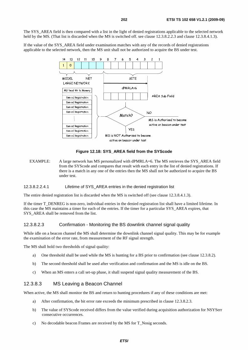
ETSI
ETSI TS 102 658 V1.2.1 (2009-09)202
The SYS_AREA field is then compared with a list in the light of denied registrations applicable to the selected network held by the MS. (That list is discarded when the MS is switched off. see clause 12.3.8.2.2.3 and clause 12.3.8.4.1.3).
If the value of the SYS_AREA field under examination matches with any of the records of denied registrations applicable to the selected network, then the MS unit shall not be authorized to acquire the BS under test.
1 0
MODEL
dPMRLA=6
12345678910111214 13
SITENET
LARGE NETWORK
AREA Sub Field
MS Read Write Memory
Denied Registration
Denied Registration
Denied Registration
Denied Registration
Denied Registration
Denied Registration
Denied Registration
Match?NO
YES
MS is NOT Authorised to become
active on beacon under test
MS is Authorised to become
active on beacon under test
Figure 12.18: SYS_AREA field from the SYScode
EXAMPLE: A large network has MS personalized with dPMRLA=6. The MS retrieves the SYS_AREA field from the SYScode and compares that result with each entry in the list of denied registrations. If there is a match in any one of the entries then the MS shall not be authorized to acquire the BS under test.
12.3.8.2.2.4.1 Lifetime of SYS_AREA entries in the denied registration list
The entire denied registration list is discarded when the MS is switched off (see clause 12.3.8.4.1.3).
If the timer T_DENREG is non-zero, individual entries in the denied registration list shall have a limited lifetime. In this case the MS maintains a timer for each of the entries. If the timer for a particular SYS_AREA expires, that SYS_AREA shall be removed from the list.
12.3.8.2.3 Confirmation - Monitoring the BS downlink channel signal quality
While idle on a beacon channel the MS shall determine the downlink channel signal quality. This may be for example the examination of the error rate, from measurement of the RF signal strength.
The MS shall hold two thresholds of signal quality:
a) One threshold shall be used while the MS is hunting for a BS prior to confirmation (see clause 12.3.8.2).
b) The second threshold shall be used after verification and confirmation and the MS is idle on the BS.
c) When an MS enters a call set-up phase, it shall suspend signal quality measurement of the BS.
12.3.8.3 MS Leaving a Beacon Channel
When active, the MS shall monitor the BS and return to hunting procedures if any of these conditions are met:
a) After confirmation, the bit error rate exceeds the minimum prescribed in clause 12.3.8.2.3.
b) The value of SYScode received differs from the value verified during acquisition authorization for NSYSerr consecutive occurrences.
c) No decodable beacon Frames are received by the MS for T_Nosig seconds.

ETSI
ETSI TS 102 658 V1.2.1 (2009-09)203
d) The user initiates a change of selected network.
e) A B_MOVE frame applicable to the MS is received. In this case the MS shall note the values of the transmit and receive frequencies from the B_MOVE frame.
f) The MS receives N_ACK(Reason=Denied) as a result of sending a random access registration frame. In the case of a random access registration request, the MS shall assume the hunt stage that it was last engaged in prior to the registration attempt.
g) After SYScode confirmation, the MS receives N_ACK(Reason=failed) as a result of random access registration procedures. In this case the MS shall assume the hunt stage that it was last engaged in prior to the registration attempt.
h) After confirmation, the MS has timed out after a random access registration procedure due to NRand_NR being reached or TRand_TC being exceeded. In this case the MS shall assume the hunt stage that it was last engaged in prior to the registration attempt.
i) After confirmation, the MS has timed-out after a random access attempt for a service request, except registration, due to NRand_NR or NRand_NE being reached or TRand_TC being exceeded.
12.3.8.3.1 Leaving a Beacon Channel Whilst Waiting for Signalling
An MS waiting for signalling shall leave the BS on which it is currently active when any of the following events as listed in clause 12.3.8.3 occur - b), c), and e). In such circumstances the MS shall retain its state of waiting for signalling during any hunting procedures and subsequent BS confirmation tests. Any timers relevant to the waiting state shall be maintained.
12.3.8.4 Registration, Power Save, and Authentication Procedures
12.3.8.4.1 General
12.3.8.4.1.1 Introduction
Registration is a method of recording the area or group of geographic areas where an MS is likely to be located within a wide area network. This information avoids searching for MSs throughout the whole network, consequently reducing call set-up time and BS loading.
A secondary feature is that it provides a means of restricting the service to individual MSs to specific BSs by allowing the network to deny other registration requests (see clause 12.3.8.4.2.5).
The registration strategy describes two types of registration. The first of these is explicit registration, where registration is achieved by means of an MS random access procedure. The second is implicit registration, where registration is achieved as the result of any Frames exchanged between a BS and an MS.
Explicit registration also enables MS to request power save. Power save is prescribed in clause 12.3.10.
12.3.8.4.1.2 The Principle
The principle of registration requires that the MS shall only retain a valid registration record where it has received confirmation that it is the same record as that currently held within the network. If an MS fails to receive a response to a registration request, this could be due to:
a) the registration request not being received by the network, in which case the network shall regard the previous successful registration by the unit as the currently-valid registration record;
b) the registration request being accepted by the network but the service answer response not being received by the MS, in which case the network shall regard the unsuccessful registration by the unit as the currently-valid registration record.
Accordingly, in such cases the MS is not able to confirm whether the network holds a valid record for the unit and if it does, whether it is the previous registration or the present registration. The MS shall therefore only replace its current registration record when a successful registration is confirmed by a suitable service answer response to the registration service random access request from the BS.
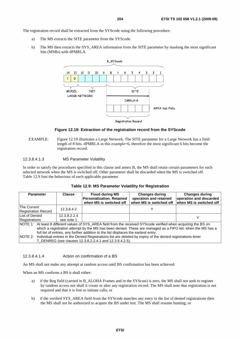
ETSI
ETSI TS 102 658 V1.2.1 (2009-09)204
The registration record shall be extracted from the SYScode using the following procedure:
a) The MS extracts the SITE parameter from the SYScode.
b) The MS then extracts the SYS_AREA information from the SITE parameter by masking the most significant bits (MSBs) with dPMRLA.
1 0
MODEL
DMRLA=6
12345678910111214 13
SITENET
LARGE NETWORK
AREA Sub Field
B_SYScode
Registration Record
Figure 12.19: Extraction of the registration record from the SYScode
EXAMPLE: Figure 12.19 illustrates a Large Network. The SITE parameter for a Large Network has a field length of 8 bits. dPMRLA in this example=6, therefore the most significant 6 bits become the registration record.
12.3.8.4.1.3 MS Parameter Volatility
In order to satisfy the procedures specified in this clause and annex B, the MS shall retain certain parameters for each selected network when the MS is switched off. Other parameter shall be discarded when the MS is switched off. Table 12.9 lists the behaviour of each applicable parameter.
Table 12.9: MS Parameter Volatility for Registration
Parameter Clause Fixed during MS Personalization. Retained when MS is switched off
Changes during operation and retained
when MS is switched off
Changes during operation and discarded when MS is switched off
The Current Registration Record 12.3.8.4.2 Y
List of Denied Registrations
12.3.8.2.2.4 see note 1
Y
NOTE 1: At least 8 different values of SYS_AREA field from the received SYScode verified when acquiring the BS on which a registration attempt by the MS has been denied. These are managed as a FIFO list: when the MS has a full list of entries, any further addition to the list displaces the earliest entry.
NOTE 2: Individual entries in the Denied Registrations list are deleted by expiry of the denied registrations timer T_DENREG (see clauses 12.3.8.2.2.4.1 and 12.3.8.4.2.5).
12.3.8.4.1.4 Action on confirmation of a BS
An MS shall not make any attempt at random access until BS confirmation has been achieved.
When an MS confirms a BS it shall either:
a) if the Reg field (carried in B_ALOHA Frames and in the SYScast) is zero, the MS shall not seek to register by random access nor shall it create or alter any registration record. The MS shall note that registration is not required and that it is free to initiate calls; or
b) if the verified SYS_AREA field from the SYScode matches any entry in the list of denied registrations then the MS shall not be authorized to acquire the BS under test. The MS shall resume hunting; or

ETSI
ETSI TS 102 658 V1.2.1 (2009-09)205
c) if the MS does not hold a successful registration record for the verified SYS_AREA, the MS shall attempt to register by random access.
Once confirmed on a BS, the MS shall not transmit any frame other than:
a) registration service random access request frame; or
b) an acknowledgement to an authentication challenge as specified in clause 12.3.11.2.
until it holds a successful registration record relating to the verified SYS_AREA unless Reg = 0;
If the MS holds a successful registration record relating to the verified SYS_AREA code, it is free to transmit any frame conforming to the requirements of the present document.
12.3.8.4.2 Registration Procedures
The procedures for explicit MS registration are prescribed in these clauses. An example of a registration is illustrated in figure 12.20.
AL AK AL
A
B
MS(A)
Uplink
Beacon
Downlink
R
Figure 12.20: Registration Exchange
12.3.8.4.2.1 Registration by Random Access
When an MS determines that it is required to register, it shall attempt to do so by random access using the procedures defined in clause 12.3.7. If the random access timeout B_RandTC expires and the MS has not sent a random access registration request, the MS shall enter the BS channel acquisition procedures.
The B_RAND for a registration are set as prescribed in table 12.10.
Table 12.10: B_RAND fields for a Registration Request
Alias Alias Alias Value Length Meaning MT 11002 4 Message Type = B_RAND (BS uplink)
PARMS
ID0 + 1 24 REGI gateway ID2 + 3 24 Calling MS ID
1102 3 Service requested is defined by MI_TYPE V N/A 2 Not Applicable for this particular message F 102 2 Comms Format = BS Uplink
EP 02 1 Non emergency service PM N/A 1 Not Applicable for this particular message
MI MI_TYPE 1012 3 Service Requested is Registration
MI_DET N/A 8 Not Applicable for this particular message
Immediately upon sending the registration request by random access, the MS shall delete its current SYS_AREA code retained from its previous registration.
Valid BS responses to the random access request are B_WACKD(Reason=Wait) more signalling to follow, B_ACKD(Reason=Reg_Accepted), B_NACKD(Reason=Reg_Refused), B_NACKD(Reason=Reg_Denied), or B_AHOY(Source Address or Gateway=SERIALI0) (see clause 12.3.11).
NOTE: SERIALI0 is the serial number identifier (see clause 13.4).
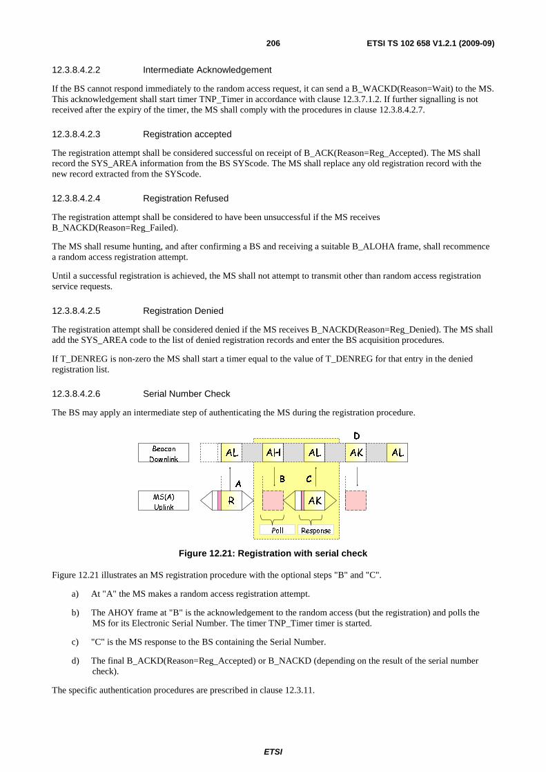
ETSI
ETSI TS 102 658 V1.2.1 (2009-09)206
12.3.8.4.2.2 Intermediate Acknowledgement
If the BS cannot respond immediately to the random access request, it can send a B_WACKD(Reason=Wait) to the MS. This acknowledgement shall start timer TNP_Timer in accordance with clause 12.3.7.1.2. If further signalling is not received after the expiry of the timer, the MS shall comply with the procedures in clause 12.3.8.4.2.7.
12.3.8.4.2.3 Registration accepted
The registration attempt shall be considered successful on receipt of B_ACK(Reason=Reg_Accepted). The MS shall record the SYS_AREA information from the BS SYScode. The MS shall replace any old registration record with the new record extracted from the SYScode.
12.3.8.4.2.4 Registration Refused
The registration attempt shall be considered to have been unsuccessful if the MS receives B_NACKD(Reason=Reg_Failed).
The MS shall resume hunting, and after confirming a BS and receiving a suitable B_ALOHA frame, shall recommence a random access registration attempt.
Until a successful registration is achieved, the MS shall not attempt to transmit other than random access registration service requests.
12.3.8.4.2.5 Registration Denied
The registration attempt shall be considered denied if the MS receives B_NACKD(Reason=Reg_Denied). The MS shall add the SYS_AREA code to the list of denied registration records and enter the BS acquisition procedures.
If T_DENREG is non-zero the MS shall start a timer equal to the value of T_DENREG for that entry in the denied registration list.
12.3.8.4.2.6 Serial Number Check
The BS may apply an intermediate step of authenticating the MS during the registration procedure.
AL AK AL
AB
D
Poll Response
AL
C
AH
MS(A)
Uplink
Beacon
Downlink
R AK
Figure 12.21: Registration with serial check
Figure 12.21 illustrates an MS registration procedure with the optional steps "B" and "C".
a) At "A" the MS makes a random access registration attempt.
b) The AHOY frame at "B" is the acknowledgement to the random access (but the registration) and polls the MS for its Electronic Serial Number. The timer TNP_Timer timer is started.
c) "C" is the MS response to the BS containing the Serial Number.
d) The final B_ACKD(Reason=Reg_Accepted) or B_NACKD (depending on the result of the serial number check).
The specific authentication procedures are prescribed in clause 12.3.11.

ETSI
ETSI TS 102 658 V1.2.1 (2009-09)207
12.3.8.4.2.7 Registration Attempt Times Out
If the MS times out from waiting for further signalling for the registration (expiry of timer TNP_Timer), it shall enter the BS acquisition procedures.
12.3.8.4.2.8 Registration Demand Received During Random Access Registration
The beacon BS shall avoid conflict in the protocol. If, while waiting for a response to a random access registration request frame, the MS receives a B_BCAST(Announcement_type=MassReg) frame applicable to the MS, the MS shall note the fields from the B_BCAST and initiate the procedure specified in clause 12.3.9.1 then continue with its registration request in accordance with the random access procedures.
12.3.8.4.2.9 No answer response Received after the maximum number of random access attempts
If no response is received within WAIT+1 framesets after the MS has transmitted NRand_NR random access attempts, the MS shall make no consequential changes to its registration record.
12.3.8.4.2.10 Registration Action on Switch-on or equivalent
If an MS determines that the BS requires MS to register, the MS shall register by random access on switch on or change of selected network.
12.3.9 Mass re-registration
A wide area network relies on the integrity of the registration records for MS location management. It is possible that the records may be suspect for many reasons including loss of connections between the various beacons in a network. This clause describes a mechanism whereby a BS may re-establish those registration records from the MS that are currently confirmed on that BS. A broadcast frame is transmitted on the BS that causes all applicable MS that are confirmed to re-register by random access. If this re-registration procedure is activated it is essential to avoid congestion from the increased random access activity that would result. To manage this process therefore, a REG_WINDOW field is transmitted in the broadcast frame that permits MS to make their random access registration attempt over an extended period of time.
An MS shall note the delay parameter REG_WINDOW from the B_BCAST(Announcement_type=MassReg) frame it receives and shall use table 12.11 to derive from it a time window to make a random access registration attempt.
The Mass registration may be used to demand a registration from a specific MS by setting the MS address in the Mass Registration Broadcast frame to the individual address of an MS and setting the Mask = 24.
12.3.9.1 Procedure for MS on receipt of Mass Re-registration Broadcast
When confirmed on a BS an MS shall make use of information B_BCAST(Announcement_type=MassReg). This frame may be transmitted on the BS to cause all MS or a subset of the MS population to re-register by random access.
An MS shall note the population subdivision contained in each B_BCAST(Announcement_type=MassReg) frame that it receives (as prescribed in clause 12.3.6.1.3) using the qualifier (Mask) and the address field from the B_BCAST frame. For Mask = 0 to 24, the frame is applicable to the MS if the "Mask" least significant bits of the B_BCAST address field match the "Mask" least significant bits of its individual address.
Table 12.11: REG_WINDOW lookup for Mass-Registration
REG_WINDOW Treg_Window REG_WINDOW Treg_Window 0 Cancel Mass Reg 8 100 1 .5 9 300 2 1 10 1 000 3 2 11 3 000 4 5 12 10 000 5 10 13 30 000 6 20 14 100 000 7 30 15 200000

ETSI
ETSI TS 102 658 V1.2.1 (2009-09)208
If the MS determines that the B_BCAST(Announcement_type=MassReg) frame is applicable, the MS shall:
a) examine the REG_WINDOW field from the B_BCAST(Announcement_type=MassReg). If the REG_WINDOW field is non-zero, the MS shall derive the window size TREG_WINDOW (in seconds) for a Random Access Registration attempt using table 12.11;
b) choose a random number (using a statistically uniform distribution) from zero to TREG_WINDOW;
c) count real time seconds until the random value is reached;
d) make a random access registration attempt using the procedures prescribed in clause 12.3.8.4. If the MS is in power save Mode, the PowerSave_RQ field in the Service_Options of the registration service request shall be set to maintain the power save Mode currently in operation;
e) also count real time seconds until the TREG_WINDOW frameset is reached. If the MS receives other applicable B_BCAST(Announcement_type=MassReg) containing a non zero REG_WINDOW field before REG_WINDOW is reached the MS shall ignore that B_BCAST frame;
f) if Power Save is in operation, the BS shall ensure that the Mass-Registration is transmitted in the wake period.
If the MS is confirmed on a BS and the MS receives other applicable B_BCAST(Announcement_type=MassReg) containing a zero REG_WINDOW field the mass re-registration procedure and any pending random access attempt shall be cancelled. If such a broadcast is received when the random access procedure is in progress that random access procedure shall be completed before the mass re-registration procedure is cancelled.
If the MS leaves the currently confirmed BS, and successfully confirms a different BS, any Mass-registration procedure shall be cancelled.
12.3.9.2 De-registration
When an MS is switched off, or a user initiated change of system is invoked, the MS may first attempt to de-register from the current system. It shall attempt to do so by random access using the procedures defined in clause 12.3.7. In the Service_Options of the registration service request the fields shall be set to IP_Inform=02, Reg_Dereg=02 and PowerSave_RQ=0002.
When an MS switch-off or change of network is performed, the MS shall start a timer T_Dereg.
Immediately upon sending the de-registration request by random access, the MS shall discard its current SYS_AREA code retained from its previous registration.
The only valid BS response to the de-register random access request shall be B_ACKD(Reason=Reg_Accepted). If the acknowledgement is received, the MS shall complete the switch off or change of network.
If timer T_Dereg expires, the MS shall abandon the de-registration procedure and complete the action of switch-off or change of network.
12.3.10 Beacon Power Save
12.3.10.1 Overview
Mode 3 systems may support a synchronous power saving feature.
An MS can synchronize to the timing parameters that have been exchanged with the BS and adopt a periodic sleep cycle. Calls to that MS shall be synchronized to the wake-up periods (power save frames) that are agreed between MS and the BS.

ETSI
ETSI TS 102 658 V1.2.1 (2009-09)209
Power Save Frame
MS Awake
MS Asleep
x x x x x x x x 0 0 0x x x x x x x x x x x 1 1 1x x x
Beacon Slot Counter
Frameset
PS_Counter
Figure 12.22: Power Save Frame Structure
The power save frames are defined by the PS_Counter field, a sub-set of the Beacon_Frameset _Counter broadcast in a SYScast2 message. A sleeping MS shall wake for a designated power save frame. If the BS has a frame or transaction for the sleeping MS, that frame shall be queued until a designated power save frame is transmitted on the BS. MS or other entity that initiates a transaction to a sleeping MS (or group of MSs) shall be queued on the BS until the designated power save frame has been reached. Figure 12.22 illustrates a power save frame. There are eight framesets available to signal MS during a designated power save frame:
a) The MS and BS shall have previously synchronized a particular wake frame.
b) The BS knows when a particular MS has woken and is able to receive signalling addressed to that MS. If several MSs are in a fleet and are party to a group call, all MSs in that particular group may share the same wakeup frame. The way in which the BS manages the power save and allocates particular wakeup frames is not prescribed in the present document.
c) Different MSs sharing a common BS may have differing power save and the BS/MSs shall be able to deal with this.
d) The SYScast2 that carries the Power Save Counter does not have to be continuously transmitted. When MS have received a Power Save SYScast2, they are able to calculate power save frames from that point. MS may then refresh by occasional appropriate SYScast2 Frames.
12.3.10.2 Power Save Procedures
12.3.10.2.1 Basic Power Save Procedures
For an MS to activate power save, it registers with the BS. In the registration service request the MS may ask for power save it wishes to employ, by sending a non-zero three bit PowerSave_RQ field with a number between 1 and 7. A registration service request with a zero PowerSave_RQ indicates that no power save is required or a previous power save is cancelled. The BS responds positively if it supports power save for that request, with a PowerSave_Offset field (length 7) in the range 0 to 1, 0 to 3, 0 to 7, 0 to 15, 0 to 31, 0 to 63 or 0 to 127.
Table 12.12: Power Save fields during MS registration
Power Save PowerSave_RQ PowerSave_Offset OFF 0 0 1:2 1 0 to 1 1:4 2 0 to 3 1:8 3 0 to 7
1:16 4 0 to 15 1:32 5 0 to 31 1:64 6 0 to 63
1:128 7 0 to 127
A PowerSave_RQ=1 indicates the MS shall sleep for one Power Save Frame and awake for the second. A "2" indicate 1awake and 3 sleeping. A "3" indicates 1 in 8 awake and so on. In this example the greatest power save would be "7" indicating 1 in 128 awake as illustrated in table 12.12.

ETSI
ETSI TS 102 658 V1.2.1 (2009-09)210
The BS responds with an acknowledgement containing a PowerSave_Offset field (the Response_Info field in the acknowledgement frame) that indicates the power save frame number that the BS shall send signalling to that particular MS. The BS may therefore average out signalling across all power save frames for differing fleets (or differing groups). The frame number is read by the MS and a mask applied according to the power save request. The answer gives the power save frame number for that power save value asked for in the registration request. The MS can then calculate when to wake for incoming traffic.
EXAMPLE: An MS requests a power save of 4 by setting the value of PowerSave_RQ = 2 in the registration service request. The BS responds with Powersave_Offset = 2.
The PS_Counter is counting up continuously. Suppose the PS_Counter at this moment = 65 decimal.
Table 12.13: Power Save Example - MS state
PS_Counter Count Mask Counter with PowerSave RQ MS state … …… . . . 65 010 00012 0 1 0 0 0 0 1 - Sleep
66 010 00102 0 1 0 0 0 1 0 - Wake
67 010 00112 0 1 0 0 0 1 1 - Sleep
68 010 01002 0 1 0 0 1 0 0 - Sleep
69 010 01012 0 1 0 0 1 0 1 - Sleep
70 010 01102 0 1 0 0 1 1 0 - Wake … …… . . . . . . . ….
Table 12.13 illustrates how a BS determines when an MS is awake. The BS applies a mask of length PowerSave_RQ. In this example the mask leaves two bits. When the masked PS_Counter equals the PowerSave_Offset the BS may signal the MS.
MS can sample a relevant SYScast2 message at any time, read the Common_Frameset Counter and determine when the wake frame will be transmitted. The MS may then sleep until a point at which its wake frame is scheduled. A frame addressed to the MS by its individual address shall cause the MS to awaken for T_Awake seconds. Each MS individually addressed or applicable group address frame transmitted on the BS or MS shall refresh T_Awake. If no Frames have been transmitted or received by the MS when T_Awake expires the MS shall return to its sleeping state retaining its previous power save settings.
If an MS awakes and receives an applicable B_AHOY frame that will result in a traffic channel being assigned, the MS shall stay awake for a time T_Pending for the Channel Grant Frames to be transmitted. When that call is completed and the MS returns to the BS, the MS shall wait for T_Awake seconds and then return to the sleeping state.
If while awake, the MS receives a B_MOVE frame, the MS shall retain its T_Awake timer and return to its sleeping state after T_Awake expires, unless the move to the replacement BS causes the MS to re-register when new power save fields shall be exchanged.
In the example illustrated in figure 12.23 displays a power save of 4:1 in operation. MS(A) an MS(B) are part of the same fleet and share the same powersave offset. When MS(A) is awake, MS(B) is awake. MS(A) makes a ransom access request at "A". The BS is aware that the powersave awake window is open and therefore sends a B_AHOY to MS(B) at point "B". MS"B" is awake, responds and the call completes.

ETSI
ETSI TS 102 658 V1.2.1 (2009-09)211
B eac on F ram es SY S cast fram es
M S (B)
Pow er Sa ve F ram es
8 8 0 m S 8 8 0 m S 8 8 0 m S 8 8 0 m S 8 8 0 m S 8 8 0 m S
M S Asleep
M S Aw ake
M S (A )
CA S E (1)
A
B C
D
rec ip ient of a fram e
Figure 12.23: Power Save Frame Example
Example 2 illustrated in figure 12.24 shows MS(A) making a random access call set-up to MS(B) at point "E". The beacon is aware of the power save window and realizes that a B_AHOY to MS(B) would be futile since MS(B) window has closed. The beacon therefore sends a ACKQ message to MS(A) to queue the call. When the beacon knows the next awake window has been reached the beacon sends the B_AHOY to MS(B) at point "G". MS(B) acknowledges it is awake and available to receive the call at point "H" and the call set-up completes.
Pow er Save F ram es8 8 0 m S 8 8 0 m S 8 8 0m S 88 0 m S 8 8 0 m S 8 8 0 m S
M S Asleep
M S Aw ake
T im eslot # 1 T im eslot # 2
M S (B)
G
CA S E (2 )
H
I
M S (A )
D elay caused by Pow er Save
rec ipient of a fram e
FE
Figure 12.24: Power Save Frame Example 2
12.3.11 Electronic Serial Number Check Procedures
An Electronic Serial Number (ESN) check is a procedure to verify that an MS is genuine.
AL
A
AH
B
AL
Response
AL
MS(A)
Uplink
Beacon
Downlink
Poll
AV
Figure 12.25: Serial Number Check
Figure 12.25 illustrates the mechanism. The BS polls the MS for its serial number. The serial number is signed by an algorithm. The algorithm is not part of the present document.
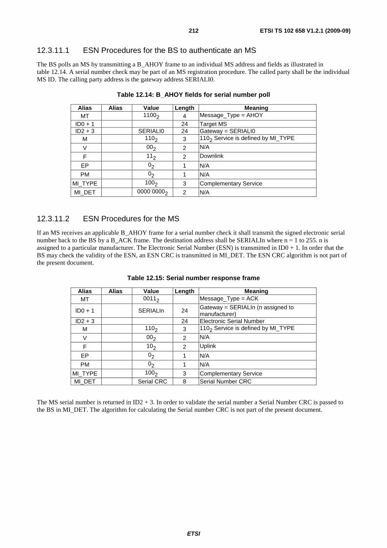
ETSI
ETSI TS 102 658 V1.2.1 (2009-09)212
12.3.11.1 ESN Procedures for the BS to authenticate an MS
The BS polls an MS by transmitting a B_AHOY frame to an individual MS address and fields as illustrated in table 12.14. A serial number check may be part of an MS registration procedure. The called party shall be the individual MS ID. The calling party address is the gateway address SERIALI0.
Table 12.14: B_AHOY fields for serial number poll
Alias Alias Value Length Meaning MT 11002 4 Message_Type = AHOY
ID0 + 1 24 Target MS ID2 + 3 SERIALI0 24 Gateway = SERIALI0
M 1102 3 1102 Service is defined by MI_TYPE
V 002 2 N/A
F 112 2 Downlink
EP 02 1 N/A
PM 02 1 N/A
MI_TYPE 1002 3 Complementary Service
MI_DET 0000 00002 2 N/A
12.3.11.2 ESN Procedures for the MS
If an MS receives an applicable B_AHOY frame for a serial number check it shall transmit the signed electronic serial number back to the BS by a B_ACK frame. The destination address shall be SERIALIn where n = 1 to 255. n is assigned to a particular manufacturer. The Electronic Serial Number (ESN) is transmitted in ID0 + 1. In order that the BS may check the validity of the ESN, an ESN CRC is transmitted in MI_DET. The ESN CRC algorithm is not part of the present document.
Table 12.15: Serial number response frame
Alias Alias Value Length Meaning MT 00112 Message_Type = ACK
ID0 + 1 SERIALIn 24 Gateway = SERIALIn (n assigned to manufacturer)
ID2 + 3 24 Electronic Serial Number M 1102 3 1102 Service is defined by MI_TYPE
V 002 2 N/A
F 102 2 Uplink
EP 02 1 N/A
PM 02 1 N/A
MI_TYPE 1002 3 Complementary Service MI_DET Serial CRC 8 Serial Number CRC
The MS serial number is returned in ID2 + 3. In order to validate the serial number a Serial Number CRC is passed to the BS in MI_DET. The algorithm for calculating the Serial number CRC is not part of the present document.
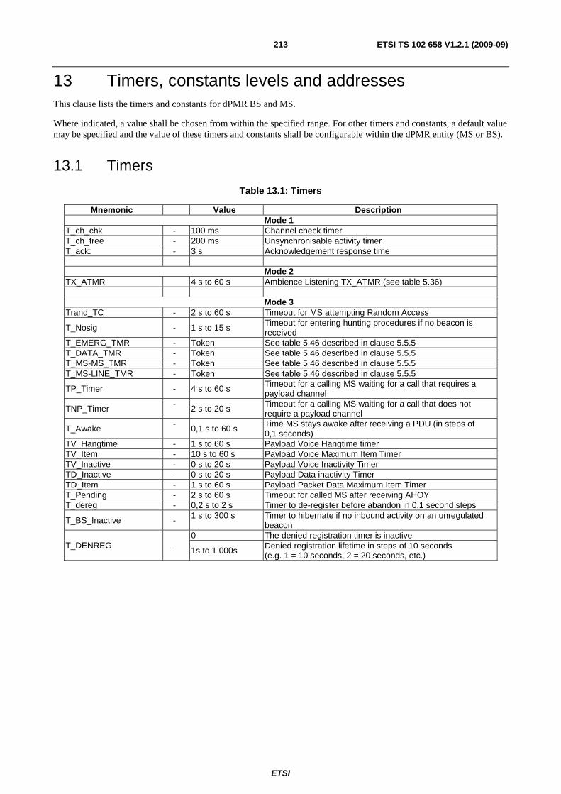
ETSI
ETSI TS 102 658 V1.2.1 (2009-09)213
13 Timers, constants levels and addresses This clause lists the timers and constants for dPMR BS and MS.
Where indicated, a value shall be chosen from within the specified range. For other timers and constants, a default value may be specified and the value of these timers and constants shall be configurable within the dPMR entity (MS or BS).
13.1 Timers
Table 13.1: Timers
Mnemonic Value Description Mode 1
T_ch_chk - 100 ms Channel check timer T_ch_free - 200 ms Unsynchronisable activity timer T_ack: - 3 s Acknowledgement response time
Mode 2 TX_ATMR 4 s to 60 s Ambience Listening TX_ATMR (see table 5.36)
Mode 3 Trand_TC - 2 s to 60 s Timeout for MS attempting Random Access
T_Nosig - 1 s to 15 s Timeout for entering hunting procedures if no beacon is received
T_EMERG_TMR - Token See table 5.46 described in clause 5.5.5 T_DATA_TMR - Token See table 5.46 described in clause 5.5.5 T_MS-MS_TMR - Token See table 5.46 described in clause 5.5.5 T_MS-LINE_TMR - Token See table 5.46 described in clause 5.5.5
TP_Timer - 4 s to 60 s Timeout for a calling MS waiting for a call that requires a payload channel
TNP_Timer - 2 s to 20 s Timeout for a calling MS waiting for a call that does not require a payload channel
T_Awake - 0,1 s to 60 s Time MS stays awake after receiving a PDU (in steps of 0,1 seconds)
TV_Hangtime - 1 s to 60 s Payload Voice Hangtime timer TV_Item - 10 s to 60 s Payload Voice Maximum Item Timer TV_Inactive - 0 s to 20 s Payload Voice Inactivity Timer TD_Inactive - 0 s to 20 s Payload Data inactivity Timer TD_Item - 1 s to 60 s Payload Packet Data Maximum Item Timer T_Pending - 2 s to 60 s Timeout for called MS after receiving AHOY T_dereg - 0,2 s to 2 s Timer to de-register before abandon in 0,1 second steps
T_BS_Inactive - 1 s to 300 s Timer to hibernate if no inbound activity on an unregulated beacon
T_DENREG - 0 The denied registration timer is inactive
1s to 1 000s Denied registration lifetime in steps of 10 seconds (e.g. 1 = 10 seconds, 2 = 20 seconds, etc.)
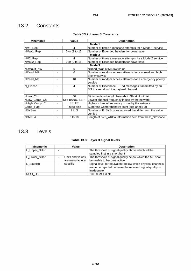
ETSI
ETSI TS 102 658 V1.2.1 (2009-09)214
13.2 Constants
Table 13.2: Layer 3 Constants
Mnemonic Value Description Mode 1
NM1_Rep - 4 Number of times a message attempts for a Mode 1 service NMax1_Rep 0 or (2 to 15) Number of Extended headers for powersave
Mode 2 NM2_Rep - 4 Number of times a message attempts for a Mode 2 service NMax2_Rep 0 or (2 to 15) Number of Extended headers for powersave
Mode 3 NDefault_NW - 5 NRand_Wait at MS switch on NRand_NR - 6 Number of random access attempts for a normal and high
priority service NRand_NE - 10 Number of random access attempts for a emergency priority
service N_Discon - 4 Number of Disconnect + End messages transmitted by an
MS to clear down the payload channel Nmax_Ch - 50 Minimum Number of channels in Short Hunt List NLow_Comp_Ch - See BAND, SEP,
FR, FT Lowest channel frequency in use by the network
NHigh_Comp_Ch - Highest channel frequency in use by the network Comp_Flag - True/False Suppress Comprehensive Hunt (see annex D) NSYSerr - 1 to 3 Number of B_SYScodes received that differ from the value
verified dPMRLA - 0 to 10 Length of SYS_AREA information field from the B_SYScode
13.3 Levels
Table 13.3: Layer 3 signal levels
Mnemonic Value Description L_Upper_SHort -
Units and values are manufacturer specific
The threshold of signal quality above which will be sampled first in a short hunt
L_Lower_SHort - The threshold of signal quality below which the MS shall be unable to become active
L_Squelch - Signal level (or equivalent) below which physical channels are to be rejected because the received signal quality is inadequate
RSSI_LO -105 dBm ± 3 dB
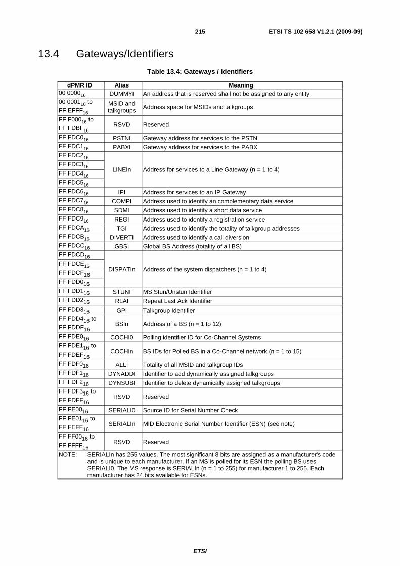
ETSI
ETSI TS 102 658 V1.2.1 (2009-09)215
13.4 Gateways/Identifiers
Table 13.4: Gateways / Identifiers
dPMR ID Alias Meaning 00 000016 DUMMYI An address that is reserved shall not be assigned to any entity 00 000116 to FF EFFF16
MSID and talkgroups Address space for MSIDs and talkgroups
FF F00016 to FF FDBF16 RSVD Reserved
FF FDC016 PSTNI Gateway address for services to the PSTN FF FDC116 PABXI Gateway address for services to the PABX FF FDC216
LINEIn Address for services to a Line Gateway (n = 1 to 4) FF FDC316
FF FDC416
FF FDC516
FF FDC616 IPI Address for services to an IP Gateway FF FDC716 COMPI Address used to identify an complementary data service FF FDC816 SDMI Address used to identify a short data service FF FDC916 REGI Address used to identify a registration service FF FDCA16 TGI Address used to identify the totality of talkgroup addresses FF FDCB16 DIVERTI Address used to identify a call diversion FF FDCC16 GBSI Global BS Address (totality of all BS) FF FDCD16
DISPATIn Address of the system dispatchers (n = 1 to 4) FF FDCE16
FF FDCF16
FF FDD016
FF FDD116 STUNI MS Stun/Unstun Identifier FF FDD216 RLAI Repeat Last Ack Identifier FF FDD316 GPI Talkgroup Identifier FF FDD416 to
FF FDDF16 BSIn Address of a BS (n = 1 to 12)
FF FDE016 COCHI0 Polling identifier ID for Co-Channel Systems FF FDE116 to
FF FDEF16 COCHIn BS IDs for Polled BS in a Co-Channel network (n = 1 to 15)
FF FDF016 ALLI Totality of all MSID and talkgroup IDs FF FDF116 DYNADDI Identifier to add dynamically assigned talkgroups FF FDF216 DYNSUBI Identifier to delete dynamically assigned talkgroups FF FDF316 to
FF FDFF16 RSVD Reserved
FF FE0016 SERIALI0 Source ID for Serial Number Check FF FE0116 to
FF FEFF16 SERIALIn MID Electronic Serial Number Identifier (ESN) (see note)
FF FF0016 to
FF FFFF16 RSVD Reserved
NOTE: SERIALIn has 255 values. The most significant 8 bits are assigned as a manufacturer's code and is unique to each manufacturer. If an MS is polled for its ESN the polling BS uses SERIALI0. The MS response is SERIALIn (n = 1 to 255) for manufacturer 1 to 255. Each manufacturer has 24 bits available for ESNs.

ETSI
ETSI TS 102 658 V1.2.1 (2009-09)216
13.5 Message Matrix's
Table 13.5: Message Description Matrix
Beacon Channel Traffic Channel
MT Uplink/ Downlink Description M1 M2/
M3 M3
00002 U/D Communication_Start header Y Y
00012 U/D Connection_Request header Y Y
00102 U/D Disconnect_Request header Y Y
00112 U/D B_ACK T_ACK (this a single frame, ACK or NACK is differentiated by the MI bits setting)
Y Y Y
01002 D Traffic Channel Maintenance Y U System_Request header (an END frame follows)
01012 U ACK header reply to a system request(a superframe follows)
01102 D System Delivery Header(a superframe follows)
01112 U/D Status_Response header (an END frame follows) Y Y
10002 U/D Status_Request header Y Y
10012 U/D BS_Command header and response
10102 U/D BS_Access header and response Y
10112 D Broadcast Y
11002 D Beacon Ahoy (B_Ahoy) Y U Beacon Random Access Request Y
11012 U/D Beacon ACK (B_ACK) Y
11102 U/D UDT_Header Y
11112 U/D UDT_Appended Message Y Y Y
Table 13.6: Call Service Matrix
M MI_TYPE Value Call Service M1 M2 M3 Y 0002 Service Requested is a voice call Y Y Y Y 0012 Service Requested is a Voice Call + Slow Data Y Y Y Y 0102 Service Requested is a T1 data call Y Y Y Y 0112 Service Requested is a T2 data call Y Y Y Y 1002 Service Requested is a T3 data call Y Y Y Y 1012 Service Requested is a Voice + embedded data call Y Y Y Y 1102 Service Requested is defined by MI_TYPE - - - Y 1112 Cancel the call service Y Y 0002 Service Requested is Short Data Y Y Y Y 0012 Service Requested is Status Delivery Y Y 0102 Service Requested is Data Polling Y Y 0112 Service Requested is Call Diversion Y Y 1002 Complementary Data Service Y Y 1012 Registration and Authentication Service Y Y 1102 Reserved Y 1112 Reserved for Powersave Y Y

ETSI
ETSI TS 102 658 V1.2.1 (2009-09)217
14 Physical Layer
14.1 General parameters The radio shall comply with the essential requirements as stated in EN 301 166-2 [4].
14.1.1 Frequency range
14.1.2 RF carrier bandwidth
The radio system operates within a 6,25 kHz RF carrier bandwidth.
14.1.3 Transmit frequency error
The maximum transmit frequency error from the assigned RF carrier centre shall be within ±625 Hz as stated in EN 301 166-2 [4].
14.1.4 Time base clock drift error
The maximum time base clock drift error shall be ±2 ppm. This error is the amount of clock drift that is acceptable during a transmission.
14.2 Modulation
14.2.1 Symbols
The modulation sends 2 400 symbols/sec with each symbol conveying 2 bits of information. The maximum deviation, D , of the symbol is defined as:
ThD 2/3=
Where:
- h is the deviation index defined for the particular modulation; and
- T is the symbol time (1/2 400) in seconds.
14.2.2 4FSK generation
This clause describes the characteristics of the constant-envelope modulation, entitled 4FSK.
14.2.2.1 Deviation index
The deviation index, h , for 4FSK is defined to be 0,29. This yields a symbol deviation of 1 050 Hz at the symbol centre. The mapping between symbols and bits is given in table 14.1.
Information Bits Symbol Mapping to 4FSK Deviation.

ETSI
ETSI TS 102 658 V1.2.1 (2009-09)218
Table 14.1: FSK symbol mapping
Information Bits Symbol 4FSK Deviation
Bit 1 Bit 0 02 12 +3 +1 050 Hz
02 02 +1 +350 Hz
12 02 -1 -350 Hz
12 12 -3 -1 050 Hz
14.2.2.2 Square root raised cosine filter
0 ≤│ f │ < (1 - α ) / 2T│H ( f )│= c o s [(T / 4α )(2π│ f │ -π ( 1 - α ) / T ]
(1 + α ) / 2T ≤│ f │ (1 - α ) / 2T ≤│ f │ < (1 + α ) / 2T
,,,
1
0
α = 0.2 T = 1/2400
* T x B aseb and F i l ter
F requency
M odulator
4 F S K
O utp ut
Information
b its inp ut
H (f )
F i lter
4 F S K De via tio n
D i-b it S y m bol D evia t ion
012 + 3 + 1 050H z
+ 350H z
-350H z
-1050H z
+ 1
-1
-3
002
102
112
* R x B aseb and F i l ter
F requency
D emod
F M IF
signal
H (f )
F i lter
D (f )
F i lter
Information
b its outp ut
0 ≤│ f │ < (1 - α ) / 2T│H ( f )│= c o s [(T / 4α )(2π│ f │ -π ( 1 - α ) / T ]
(1 + α ) / 2T ≤│ f │ (1 - α ) / 2T ≤│ f │ < (1 + α ) / 2T
,,,
1
0
│D ( f )│=s in (π f T )π f T
α = 0.2 T = 1/2400
Figure 14.0

ETSI
ETSI TS 102 658 V1.2.1 (2009-09)219
14.2.2.3 4FSK Modulator
The 4FSK modulator consists of a Square Root Raised Cosine Filter, cascaded with a frequency modulator as illustrated in figure 14.1. The Square Root Raised Cosine Filter is described in clause 14.2.2.2.
F(f )
Filter
4FSKFrequency
Modulator Output
Information
bits input
Figure 14.1: 4FSK Modulator

ETSI
ETSI TS 102 658 V1.2.1 (2009-09)220
Annex A (normative): Standard User Interface It is recognized that manufacturers of MSs may wish to exercise design independence in their products and, accordingly, the requirements of these annexes are only applicable to equipment where the manufacturer has declared compliance with the "Standard User Interface".
A.1 Numbering and dialling plan
A.1.1 Introduction to the numbering and dialling plan This annex is intended to:
a) define the user visible numbering (User Interface domain); and
b) dialling in an MS for accessing other MS(s) over the AI; and
c) to describe how the visible user numbering and dial strings may be mapped on to the AI.
The Man Machine Interface (MMI) issues have been addressed in these annex only to the extent of those strictly related to numbering and dialling.
It should be ensured in the MS implementation, that no non-deterministic user input results in an ambiguous call set-up attempt over the Air Interface. For example, if a user inputs a dialled string of digits that is not assigned to any of the presented dialling algorithms, then the MS should not try to establish the call and appropriate feedback or alert should be given to the user.
As not to restrict manufacturers' independence, it is envisaged that dialling selection may be initiated in many ways. Some methods are:
a) direct number entry via a keypad;
b) mode selection buttons; and
c) soft key menu selection.
The dialling method may vary according to the MS terminal type. This annex is applicable to MSs with a basic CCITT number keypad, as illustrated in figure A.1 and/or with a display capable of displaying the decimal numbers "0" to "9" and the keys "*" and "#". However, manufacturers may employ other keypad layouts.
1 2 3
4 5 6
7 8 9
* 0 #
Figure A.1: CCITT keypad layout
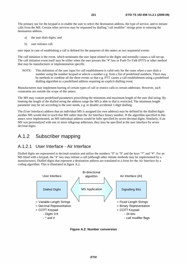
ETSI
ETSI TS 102 658 V1.2.1 (2009-09)221
The primary use for the keypad is to enable the user to select the destination address, the type of service, and to initiate calls from the MS. Certain other services may be requested by dialling "call modifier" strings prior to entering the destination address.
a) the user dials digits; and
b) user initiates call.
user input in case of establishing a call is defined for the purposes of this annex as two sequential events:
The call initiation is the event, which terminates the user input related to the digits and normally causes a call set-up. The call initiation event itself may be either when the user presses the "#" key or Push-To-Talk (PTT) or other method that may be manufacturer or implementation specific.
NOTE: This definition of the user input for call establishment is valid only for the cases when a user dials a number using the number keypad or selects a number e.g. from a list of predefined numbers. There may be methods to combine all the three events so that e.g. PTT causes a call establishment using a predefined dialling algorithm to a predefined address requiring no explicit dialling event.
Manufacturers may implement barring of certain types of call or restrict calls to certain addresses. However, such constraints are outside the scope of this annex.
The MS may contain predefined parameters prescribing the minimum and maximum length of the user dial string. By limiting the length of the dialled string the address range the MS is able to dial is restricted. The minimum length parameter may be set according to the user needs, e.g. to disable accidental 1-digit dialling.
The (User Interface) address that an individual MS is assigned (its own address) may be defined by the dialled digits another MS would dial to reach that MS rather than the Air Interface binary number. If the algorithm specified in this annex were implemented, an MS individual address would be fully specified by seven decimal digits. Similarly, if an MS was personalized with one or more talkgroup addresses, they may be specified at the user interface by seven decimal digits.
A.1.2 Subscriber mapping
A.1.2.1 User Interface - Air Interface
Dialled digits are represented in decimal notation and utilize the numbers "0" to "9" and the keys "*" and "#". For an MS fitted with a keypad, the "#" key may initiate a call (although other initiate methods may be implemented by a manufacturer). Dialled digits that represent a destination address are translated to a form for the Air Interface by a coding algorithm. This is illustrated in figure A.2.
Signalling BitsDialled Digits
Air Interface (AI)User Interface
= Variable Length Strings= Decimal Representation= CCITT Keypad - Digits 0-9 - * and #
= Fixed Length Strings= Binary Representation= CCITT Keypad - 24 bits - call modifier flags
Bi-directional algorithm
MS Application
Figure A.2: Number conversion
ETSI
ETSI TS 102 658 V1.2.1 (2009-09)222
Address fields in the Air-Interface domain structure has a length of 24 bits.
The content of a 24-bit AI MS address field may represent:
a) an MS individual address;
b) an MS talkgroup address.
The Air Interface provides call services for voice and data. The AI also permits the call services to be modified. The application that converts the User Interface to the Air Interface recognizes the "call modifier" and request the lower layers to set appropriate bits in the messages carried between the entities. At the User Interface, the "call modifier" is indicated by preceding the destination address digits with additional "call modifier" digits.
A.1.2.1.1 Mapping for MS address space
Each call is made to a numeric or non-numeric address (with "wildcards"). The mapping between the User-Interface domain and the Air Interface uses a reversible coding algorithm.
MS are able to establish the call type from analysis of the decoded Air Interface address. There are a number of methods by which an MS may distinguish between talkgroup and individual calls and these are described in the following clauses.
A.1.2.1.1.1 The concept of the wildcard character
The MS may discriminate a talkgroup call from an individual call by the use of the "wildcard".
In the User Interface domain structure, if the dialled string represents an MS address, and contains a "*" in any of the four least significant characters, then that MS address represents a talkgroup of MSs. The "*" character is the "wildcard" and represents all numeric values in that digit position, as defined in examples 1 to 3.
EXAMPLE 1: The user dials "012345*" means that the MS is addressing 10 separate MSs whose individual addresses are "0123450", "0123451", "0123452", "0123453", "0123454", "0123455", "0123456", "0123457", "0123458", and "0123459".
EXAMPLE 2: The user dials "01234*6" means the MS is addressing 10 separate MSs whose individual addresses are "0123406", "0123416", "0123426", "0123436", "0123446", "0123456", "0123466", "0123476", "0123486", and "0123496".
EXAMPLE 3: Wildcards may be combined. The user dials "01234**" represents 100 MSs in the range "0123400" to "0123499".
For operators who have no interest in this method of defining talkgroups, the "wildcard" feature may be disabled by MS programming.
A.1.2.1.1.2 The concept of stored parameters
The MS equipment may contain predefined parameters prescribing the MS addresses that can be interpreted as talkgroup addresses. These addresses may be stored as a list programmed during manufacture or before connecting an MS into service.
A.1.2.1.1.3 The concept of ad-hoc arrangement
The MS equipment may simply rely on a range of addresses that all equipment is known to be talkgroup addresses.
A.1.2.1.1.4 The rules for the sender
The MS codes the dialled user digits to a 24 bit Air Interface address by using the reversible algorithm B2.
A.1.2.1.1.5 The rules for the recipient
These rules determine whether a call is to a talkgroup or individual address and will be accepted by an MS. (All reference to MS in this clause refer to the recipient.)
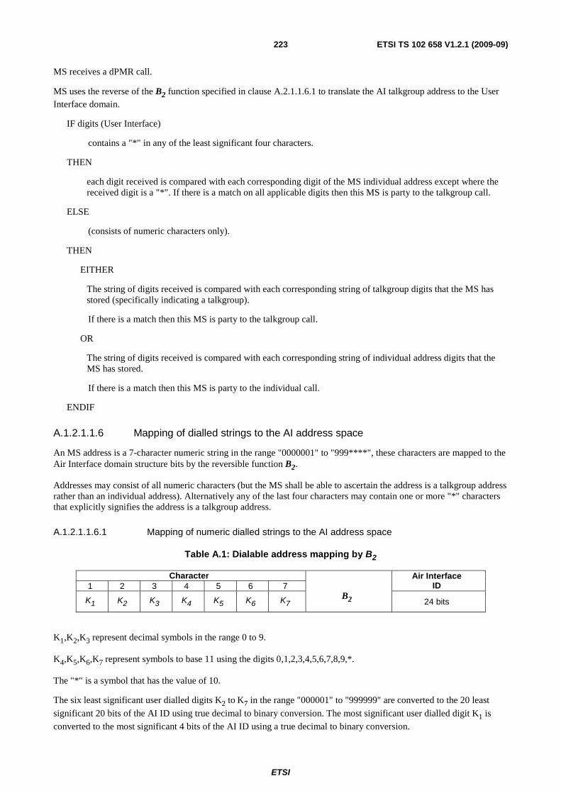
ETSI
ETSI TS 102 658 V1.2.1 (2009-09)223
MS receives a dPMR call.
MS uses the reverse of the B2 function specified in clause A.2.1.1.6.1 to translate the AI talkgroup address to the User Interface domain.
IF digits (User Interface)
contains a "*" in any of the least significant four characters.
THEN
each digit received is compared with each corresponding digit of the MS individual address except where the received digit is a "*". If there is a match on all applicable digits then this MS is party to the talkgroup call.
ELSE
(consists of numeric characters only).
THEN
EITHER
The string of digits received is compared with each corresponding string of talkgroup digits that the MS has stored (specifically indicating a talkgroup).
If there is a match then this MS is party to the talkgroup call.
OR
The string of digits received is compared with each corresponding string of individual address digits that the MS has stored.
If there is a match then this MS is party to the individual call.
ENDIF
A.1.2.1.1.6 Mapping of dialled strings to the AI address space
An MS address is a 7-character numeric string in the range "0000001" to "999****", these characters are mapped to the Air Interface domain structure bits by the reversible function B2.
Addresses may consist of all numeric characters (but the MS shall be able to ascertain the address is a talkgroup address rather than an individual address). Alternatively any of the last four characters may contain one or more "*" characters that explicitly signifies the address is a talkgroup address.
A.1.2.1.1.6.1 Mapping of numeric dialled strings to the AI address space
Table A.1: Dialable address mapping by B2
Character
B2
Air Interface ID 1 2 3 4 5 6 7
K1 K2 K3 K4 K5 K6 K7 24 bits
K1,K2,K3 represent decimal symbols in the range 0 to 9.
K4,K5,K6,K7 represent symbols to base 11 using the digits 0,1,2,3,4,5,6,7,8,9,*.
The "*" is a symbol that has the value of 10.
The six least significant user dialled digits K2 to K7 in the range "000001" to "999999" are converted to the 20 least
significant 20 bits of the AI ID using true decimal to binary conversion. The most significant user dialled digit K1 is
converted to the most significant 4 bits of the AI ID using a true decimal to binary conversion.

ETSI
ETSI TS 102 658 V1.2.1 (2009-09)224
Figure A.3: B2 Algorithm
The following steps are needed to convert the dialled digits to an ID in the AI domain:
a) take the first digit (0 to 9) and multiply by 1 464 100;
b) take the second digit (0 to 9), multiply by 146 410;
c) take the third digit (0 to 9) and multiply by 14 641;
d) take the fourth digit (0 to 9) or * (* has a value of 10) and multiply by 1 331;
e) take the fifth digit (0 to 9) or * (* has a value of 10) and multiply by 121;
f) take the sixth digit (0 to 9) or * (* has a value of 10) and multiply by 11;
g) take the seventh digit (0 to 9) or * (* has a value of 10);
h) add c) to i); and
i) convert the sum to a 24-bit binary number.
Examples are illustrated in table A.2.
Table A.2: Examples of address translation
User-Interface Air-Interface (Hex) Air Interface (Binary) 1234567 1B 91 FD16 0001 1011 1001 0001 1111 11012
468956* 68 BF 0816 0110 1000 1011 1111 0000 10002
012345* 02 C0 0A16 0000 0010 1100 0000 0000 10102
0123460 02 C0 0B16 0000 0010 C000 0000 0000 10112
999**** DF 67 6716 1101 1111 0110 0111 0110 01112
A.1.2.2 Addresses
An MS is pre-programmed with at least one individual identity.
An MS is permitted to have multiple individual identities and one or more talkgroup identities.
Where an MS has more than one individual identity then one of these shall be assigned as the primary individual identity. This primary individual identity is the one that shall be used for all forms of abbreviated or masked dialling (see clauses A.3.4.1.2 and A.3.4.1.3).
An MS may contain a list of talkgroup identities, which may be pre-programmed or dynamically updated (manually or over the AI).
The User Interface domain maps to the AI address space by the B2 algorithm.
A.1.2.3 Conversion rules
A.1.2.3.1 MS addresses
An MS address in the User-Interface structure is defined as 7 characters of which for an individual MS address contain the characters "0" to "9". For a talkgroup address the three most significant contain the characters "0" to "9" and least significant four characters contain the characters "0" to "9" or "*".

ETSI
ETSI TS 102 658 V1.2.1 (2009-09)225
A.1.2.3.2 Limiting the length of the destination address
The MS equipment may contain predefined parameters prescribing the minimum and maximum length of the user dial string. By limiting the length of the dialled string, the address range that the MS is able to dial is restricted.
A.1.2.3.3 All talkgroup address
The All Call dialled string "n******" (All Call within a prefix) is mapped as illustrated in table A.3.
Table A.3: Mapping of prefixed All Call to the AI
User dialled string Air Interface ID Meaning "0******" 18 CC 3E16 All Talkgroup ID0
"1******" 2F 23 6216 All Talkgroup ID1
etc. etc. etc. "9******" E1 DC 8216 All Talkgroup ID9
The All Call dialled string: "******" is mapped to the All Talkgroup ID15 and addresses all MSs irrespective of their prefix.
Table A.4: Mapping of all prefix call to the AI
User dialled string Air Interface ID Meaning "*******" F8 33 A616 All Talkgroup ID15
A.1.3 User dialling plan
A.1.3.1 User numbering
All dialled strings, as defined in the clause A.3 of the present document, are read from left to right and are dialled in the sequence in which they are read. Throughout this clause all representations of dialled strings are underlined.
MSs may only be required to dial sufficient numbers of characters unambiguously define the destination and service required.
A.1.3.1.1 Dialling method
To maximize channel utilization, the user should enter a string of digits and then press a button to initiate the call.
The "#" key or a dedicated "send" key is used to initiate the call. The "#" key has an additional purpose of modifying the call type or priority.
A.1.3.1.2 Call Type determination
Underlying signalling and system functionality is hidden from the user. MSs determine the call type and function from the length and content of the dialled string.
A.1.3.1.3 Call modifier strings
Dialled strings that commence with a hash "#" provide secondary uses for the keypad.
Secondary dialling functions may be as follows:
a) Status Call.
b) Broadcast Call.
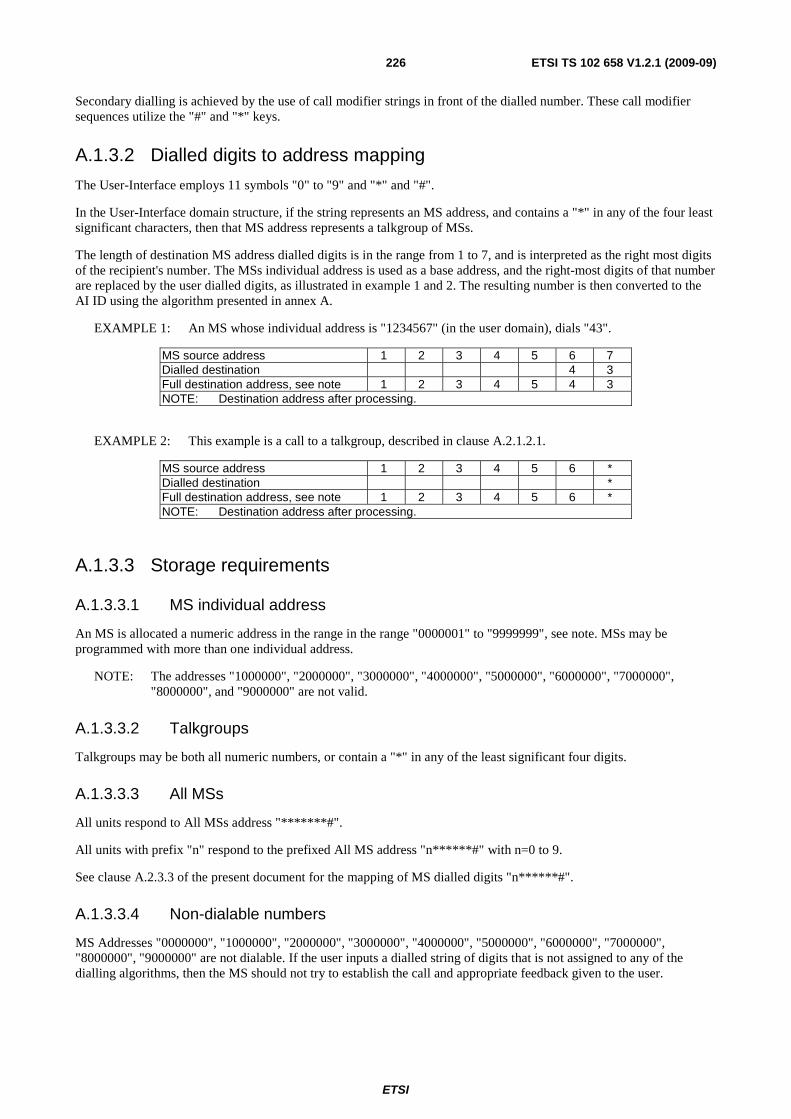
ETSI
ETSI TS 102 658 V1.2.1 (2009-09)226
Secondary dialling is achieved by the use of call modifier strings in front of the dialled number. These call modifier sequences utilize the "#" and "*" keys.
A.1.3.2 Dialled digits to address mapping
The User-Interface employs 11 symbols "0" to "9" and "*" and "#".
In the User-Interface domain structure, if the string represents an MS address, and contains a "*" in any of the four least significant characters, then that MS address represents a talkgroup of MSs.
The length of destination MS address dialled digits is in the range from 1 to 7, and is interpreted as the right most digits of the recipient's number. The MSs individual address is used as a base address, and the right-most digits of that number are replaced by the user dialled digits, as illustrated in example 1 and 2. The resulting number is then converted to the AI ID using the algorithm presented in annex A.
EXAMPLE 1: An MS whose individual address is "1234567" (in the user domain), dials "43".
MS source address 1 2 3 4 5 6 7 Dialled destination 4 3 Full destination address, see note 1 2 3 4 5 4 3 NOTE: Destination address after processing.
EXAMPLE 2: This example is a call to a talkgroup, described in clause A.2.1.2.1.
MS source address 1 2 3 4 5 6 * Dialled destination * Full destination address, see note 1 2 3 4 5 6 * NOTE: Destination address after processing.
A.1.3.3 Storage requirements
A.1.3.3.1 MS individual address
An MS is allocated a numeric address in the range in the range "0000001" to "9999999", see note. MSs may be programmed with more than one individual address.
NOTE: The addresses "1000000", "2000000", "3000000", "4000000", "5000000", "6000000", "7000000", "8000000", and "9000000" are not valid.
A.1.3.3.2 Talkgroups
Talkgroups may be both all numeric numbers, or contain a "*" in any of the least significant four digits.
A.1.3.3.3 All MSs
All units respond to All MSs address "*******#".
All units with prefix "n" respond to the prefixed All MS address "n******#" with n=0 to 9.
See clause A.2.3.3 of the present document for the mapping of MS dialled digits "n******#".
A.1.3.3.4 Non-dialable numbers
MS Addresses "0000000", "1000000", "2000000", "3000000", "4000000", "5000000", "6000000", "7000000", "8000000", "9000000" are not dialable. If the user inputs a dialled string of digits that is not assigned to any of the dialling algorithms, then the MS should not try to establish the call and appropriate feedback given to the user.

ETSI
ETSI TS 102 658 V1.2.1 (2009-09)227
A.1.3.3.5 Talkgroup recognition
A.1.3.3.5.1 All numeric talkgroups
Each MS has storage allocated for numeric talkgroup addresses. The table is populated during MS personalization by the user. The sender (MS) may use entries in this table to establish that the destination address is a talkgroup rather than an individual address.
The talkgroup table contains entries consisting of the full talkgroup address consisting of 7 characters as illustrated in the example.
EXAMPLE: The sender (MS) whose individual address is "1234561" has the destination "1234567" stored in its talkgroup table. The user enters a single digit "7" as the destination address. The full destination address is formed from the dialled digit(s) and the MS own individual address.
MS source address 1 2 3 4 5 6 1 Dialled destination 7 Full (Talkgroup), see note 1 2 3 4 5 6 7 NOTE: Destination address after processing.
The talkgroup table is searched for a match. In this example there is a match so the destination address is a talkgroup addresses
A.1.3.3.5.2 Talkgroups defined by wildcards
The dialled string is examined by the initiating MS. If the destination is identified as a talkgroup because the address contains a "wildcard" character in one of the four least significant digits then call set-up procedure is to a talkgroup as illustrated in the example. Abbreviated dialling minimizes the number of dialled digits. An advantage of using "wildcard" to define talkgroups is that no pre-arrangement is necessary, i.e. there is no need for a talkgroup table or other MS configuration to recognize an address as a talkgroup.
EXAMPLE:
MS source address 1 2 3 4 5 6 1 Dialled destination * Full destination address, see note 1 2 3 4 5 6 * NOTE: Destination address after processing.
A.1.3.3.5.3 MS receives a talkgroup call
The recipient MS applies the reverse B2 to recover the dialled digits K1 to K7.
a) If the received digits contain a "*" in the digits K4 to K7 then:
- each digit is compared in turn with the corresponding digit of the MS individual identity looking for a match. If an "*" is encountered then a match for that digit is assumed.
- If the received digits are all numeric then:
� the digits K1 to K7 are compared with each of the entries in the talkgroup table looking for a match
(after each entry in the table has been expanded to the full 7 address digits as described in clause A.3.3.5.1).
There shall be a match between the received digit and an entry in the talkgroup table for the MS to respond to the talkgroup call.
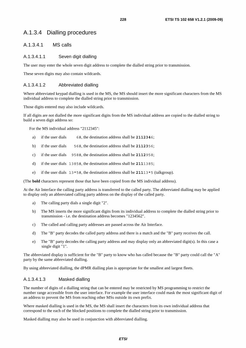
ETSI
ETSI TS 102 658 V1.2.1 (2009-09)228
A.1.3.4 Dialling procedures
A.1.3.4.1 MS calls
A.1.3.4.1.1 Seven digit dialling
The user may enter the whole seven digit address to complete the dialled string prior to transmission.
These seven digits may also contain wildcards.
A.1.3.4.1.2 Abbreviated dialling
Where abbreviated keypad dialling is used in the MS, the MS should insert the more significant characters from the MS individual address to complete the dialled string prior to transmission.
Those digits entered may also include wildcards.
If all digits are not dialled the more significant digits from the MS individual address are copied to the dialled string to build a seven digit address so:
For the MS individual address "2112345":
a) if the user dials 6#, the destination address shall be 2112346;
b) if the user dials 56#, the destination address shall be 2112356;
c) if the user dials 958#, the destination address shall be 2112958;
d) if the user dials 1385#, the destination address shall be 2111385;
e) if the user dials 13*5#, the destination address shall be 21113*5 (talkgroup).
(The bold characters represent those that have been copied from the MS individual address).
At the Air Interface the calling party address is transferred to the called party. The abbreviated dialling may be applied to display only an abbreviated calling party address on the display of the called party.
a) The calling party dials a single digit "2".
b) The MS inserts the more significant digits from its individual address to complete the dialled string prior to transmission - i.e. the destination address becomes "1234562".
c) The called and calling party addresses are passed across the Air Interface.
d) The "B" party decodes the called party address and there is a match and the "B" party receives the call.
e) The "B" party decodes the calling party address and may display only an abbreviated digit(s). In this case a single digit "1".
The abbreviated display is sufficient for the "B" party to know who has called because the "B" party could call the "A" party by the same abbreviated dialling.
By using abbreviated dialling, the dPMR dialling plan is appropriate for the smallest and largest fleets.
A.1.3.4.1.3 Masked dialling
The number of digits of a dialling string that can be entered may be restricted by MS programming to restrict the number range accessible from the user interface. For example the user interface could mask the most significant digit of an address to prevent the MS from reaching other MSs outside its own prefix.
Where masked dialling is used in the MS, the MS shall insert the characters from its own individual address that correspond to the each of the blocked positions to complete the dialled string prior to transmission.
Masked dialling may also be used in conjunction with abbreviated dialling.

ETSI
ETSI TS 102 658 V1.2.1 (2009-09)229
Those digits entered may also include wildcards.
EXAMPLE:
For the MS individual address of 3456789.
The dialling string entry mask is [X] [X] [X] [X] [ ] [ ] [ ].
The user may only enter digits in those positions not marked with an X.
- If the user enters 888# then the resulting dialling string is be 3456888.
- If the user enters 8# then the resulting dialling string is be 3456788.
- If the user enters 88*# then the resulting dialling string is be 345688* (Talkgroup call).
A.1.3.4.2 Gateway Calls
Mode 2 and Mode 3 systems supports calls through gateways to and from line connected destinations. The dialled strings to address these destinations is described in this clause.
A.1.3.4.2.1 Telephone call
PSTN telephone numbers may be dialled using two alternative methods.
A.1.3.4.2.1.1 Telephone numeric padding format
PSTN telephone numbers are called by entering the "9" or a "0" followed by a 7 to 20 digit telephone number followed by the "#" character to indicate that dialling is complete and that the call is to be initiated.
EXAMPLE 1: "91234530#" should initiate a telephone call to the telephone subscriber "1234530". Likewise dialling "001256484530#" should dial telephone subscriber "01256484530".
Telephone numbers can be of length 7 to 20 digits and can have any digit 0 to 9 in any position in the dialled string.
Any telephone numbers that are outside this range (e.g. four digit PSTN numbers) should require to be padded with leading digits to a length that can be dialled. This padding may be stripped by the telephone interconnect (at the physical gateway) to ensure correct dialling.
If the first dialled digit is the "#" key and the key is held for more than DIALn seconds, the international dialling symbol "+" should be inserted into the dialled string, replacing the "*" character. For an MS employing a display, the "+" character should be shown.
EXAMPLE 2: "+441253123456#" should initiate a telephone call to the U.K. The number is compiled as follows: "+" international gateway "44" U.K "1253" National Code "123456" Local Number.
A.1.3.4.2.1.2 Telephone star modifier format
PSTN telephone numbers are called by entering "*9" or "*0" followed by a 3 to 20 digit telephone number followed by the "#" character to indicate that dialling is complete and that the call is to be initiated.
EXAMPLE: "*9845#" should initiate a PSTN telephone call to the telephone subscriber "845". Likewise dialling "*035276#" should dial telephone subscriber "35276".
Telephone numbers can be of length 3 to 20 digits and can have any digit 0 to 9 in any position in the dialled string.
A.1.3.4.2.2 PABX call
PABX telephone numbers may be dialled using two alternative methods.
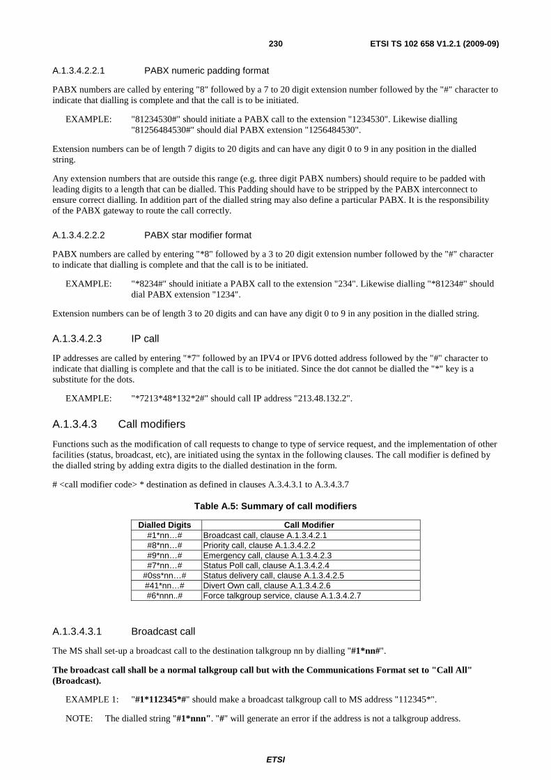
ETSI
ETSI TS 102 658 V1.2.1 (2009-09)230
A.1.3.4.2.2.1 PABX numeric padding format
PABX numbers are called by entering "8" followed by a 7 to 20 digit extension number followed by the "#" character to indicate that dialling is complete and that the call is to be initiated.
EXAMPLE: "81234530#" should initiate a PABX call to the extension "1234530". Likewise dialling "81256484530#" should dial PABX extension "1256484530".
Extension numbers can be of length 7 digits to 20 digits and can have any digit 0 to 9 in any position in the dialled string.
Any extension numbers that are outside this range (e.g. three digit PABX numbers) should require to be padded with leading digits to a length that can be dialled. This Padding should have to be stripped by the PABX interconnect to ensure correct dialling. In addition part of the dialled string may also define a particular PABX. It is the responsibility of the PABX gateway to route the call correctly.
A.1.3.4.2.2.2 PABX star modifier format
PABX numbers are called by entering "*8" followed by a 3 to 20 digit extension number followed by the "#" character to indicate that dialling is complete and that the call is to be initiated.
EXAMPLE: "*8234#" should initiate a PABX call to the extension "234". Likewise dialling "*81234#" should dial PABX extension "1234".
Extension numbers can be of length 3 to 20 digits and can have any digit 0 to 9 in any position in the dialled string.
A.1.3.4.2.3 IP call
IP addresses are called by entering "*7" followed by an IPV4 or IPV6 dotted address followed by the "#" character to indicate that dialling is complete and that the call is to be initiated. Since the dot cannot be dialled the "*" key is a substitute for the dots.
EXAMPLE: "*7213*48*132*2#" should call IP address "213.48.132.2".
A.1.3.4.3 Call modifiers
Functions such as the modification of call requests to change to type of service request, and the implementation of other facilities (status, broadcast, etc), are initiated using the syntax in the following clauses. The call modifier is defined by the dialled string by adding extra digits to the dialled destination in the form.
# <call modifier code> * destination as defined in clauses A.3.4.3.1 to A.3.4.3.7
Table A.5: Summary of call modifiers
Dialled Digits Call Modifier #1*nn…# Broadcast call, clause A.1.3.4.2.1 #8*nn…# Priority call, clause A.1.3.4.2.2 #9*nn…# Emergency call, clause A.1.3.4.2.3 #7*nn…# Status Poll call, clause A.1.3.4.2.4
#0ss*nn…# Status delivery call, clause A.1.3.4.2.5 #41*nn…# Divert Own call, clause A.1.3.4.2.6 #6*nnn..# Force talkgroup service, clause A.1.3.4.2.7
A.1.3.4.3.1 Broadcast call
The MS shall set-up a broadcast call to the destination talkgroup nn by dialling "#1*nn#".
The broadcast call shall be a normal talkgroup call but with the Communications Format set to "Call All" (Broadcast).
EXAMPLE 1: "#1*112345*#" should make a broadcast talkgroup call to MS address "112345*".
NOTE: The dialled string "#1*nnn". "#" will generate an error if the address is not a talkgroup address.

ETSI
ETSI TS 102 658 V1.2.1 (2009-09)231
EXAMPLE 2: If the MS calling party address is "1234567". "#1**#" should make a broadcast talkgroup call to "123456*" (i.e. to "1234560", "1234561", etc. "1234569").
A.1.3.4.3.2 Priority call
The MS may set up a high priority call to the destination address nn by dialling "#8*nn#".
EXAMPLE 1: To make a high priority call from MS 1122345 to MS 1122346 dial "#8*6#".
EXAMPLE 2: To make a high priority talkgroup call from MS 1122345 to MSs fleet 112234* dial "#8**#".
EXAMPLE 3: To make a high priority individual call to PABX extension 234 using start modifier format dial "#8**8234#".
A.1.3.4.3.3 Emergency Call
The MS may set-up an emergency priority call to the destination address nn dialling "#9*nn#".
EXAMPLE 1: To make an emergency call from MS 1122345 to talkgroup MSs 11223*6 dial "#9**6#".
EXAMPLE 2: To make an emergency call to telephone number 456 (using telephone star modifier format) dial "#9**9456#".
EXAMPLE 3: To make an emergency call to telephone number 01772123456 (using telephone numeric padding format) dial "#9*901772123456#".
A.1.3.4.3.4 Status poll call
The string "#0ss*nnn#" causes the MS to set up a status poll to the destination address nnn.
A.1.3.4.3.5 Status delivery call
The string "#0ss*nnn#" causes the MS to set up a status call to the destination address nnn. The status digits "ss" are numeric in the range 0 to 31.
Entry of a status value of greater than 31 shall generate an error warning to the user.
A.1.3.4.3.6 Divert own call
The string "#41*nn#" instructs a repeater BS to offer the number "nn..n" back to any caller who is attempting to make a call to the originating MS as an alternative destination for the call. The number to which calls are to be diverted, and which follows the code, should be any number which the user is able to dial between 0 and 99.
The MS should instruct the repeater BS to cancel the diverted state dialling "#41#" or "#41*#".
A.1.3.4.3.7 Force talkgroup service
The string "#6*nnn..#" causes the MS to set up a talkgroup call to destination talkgroup nnn. where nnn. is a numeric string of length from 1 to 7 digits.
EXAMPLE: To make a talkgroup call from MS 1122345 to talkgroup MSs 1122356 dial "#6*1122356#". In this case dialling "#6*56#" would achieve the same result.
A.1.3.4.4 Call set-up abandon or call complete
"##" may be dialled after digits and a terminator have been entered on the keyboard. If the radio unit has not transmitted a call request, it shall abandon the call.
ETSI
ETSI TS 102 658 V1.2.1 (2009-09)232
Annex B (informative): Beacon Channel Hunting Procedures
B.1 Introduction In order to locate a valid Beacon, the MS hunts through a list candidate physical channels until an appropriate Beacon is selected and confirmed. This Beacon hunting may involve a variety of hunting sequences depending on the circumstances of the hunt. This annex shows a framework for MS hunting strategy.
The MS may use information from any of the messages that contain the SYScode field to use for verification tests specified in clause 12.3.8.2.2.1.
The Beacon Channel Hunting Procedure stages are:
a) The "resuming a Beacon hunt channel" allows an MS, after a period of activity on a traffic channel, to resume the Beacon on which it was last confirmed prior to the payload Goto Channel message.
b) The "commanded Beacon hunt channel" is employed when an MS is directed on the Beacon to a particular Beacon (from a B_MOVE or T_CLEAR message) or seeks to regain a Beacon after a period of inactivity on the selected network (due to being switched off or a user-initiated change of selected network when details of the last confirmed Beacon channel has been stored by the MS in non-volatile storage).
"Short Hunt Sequence": A hunting sequence, which samples all physical channel frequencies likely to be employed as Beacons by the selected network. A list of Nmax_Ch likely logical candidate physical channel frequency pairs is held in MS fixed non-volatile storage for the selected network. The MS should have the storage for up to 64 values of the logical physical channel information element defining the extent of the "short hunt sequence". Unused storage locations are marked such that the MS may ignore them. Particular Physical channel numbers may be stored in the list numerous times to provide a bias to that particular Beacon.
a) "Comprehensive Hunt Sequence". A hunting sequence, that samples all possible physical channel numbers in use by the network. This hunting sequence provides a contingency to allow Beacons to be acquired even when physical channel numbers not normally employed for this purpose are in use. The "comprehensive hunt sequence" may be temporarily suspended to sample likely physical channels or repeat a "short hunt sequence". The lowest Low_Comp_Ch and highest High_Comp_Ch is held in the MS fixed non-volatile storage.
NOTE 1: The "Comprehensive Hunt Sequence" may be suppressed by network personalization.
When carrying out a "resuming a Beacon hunt channel" or "commanded Beacon hunt channel" the hunting procedure is considered complete when the MS has tuned directly to the physical channel and has carried out the appropriate verification and confirmation procedures specified in clause 12.3.8.2.
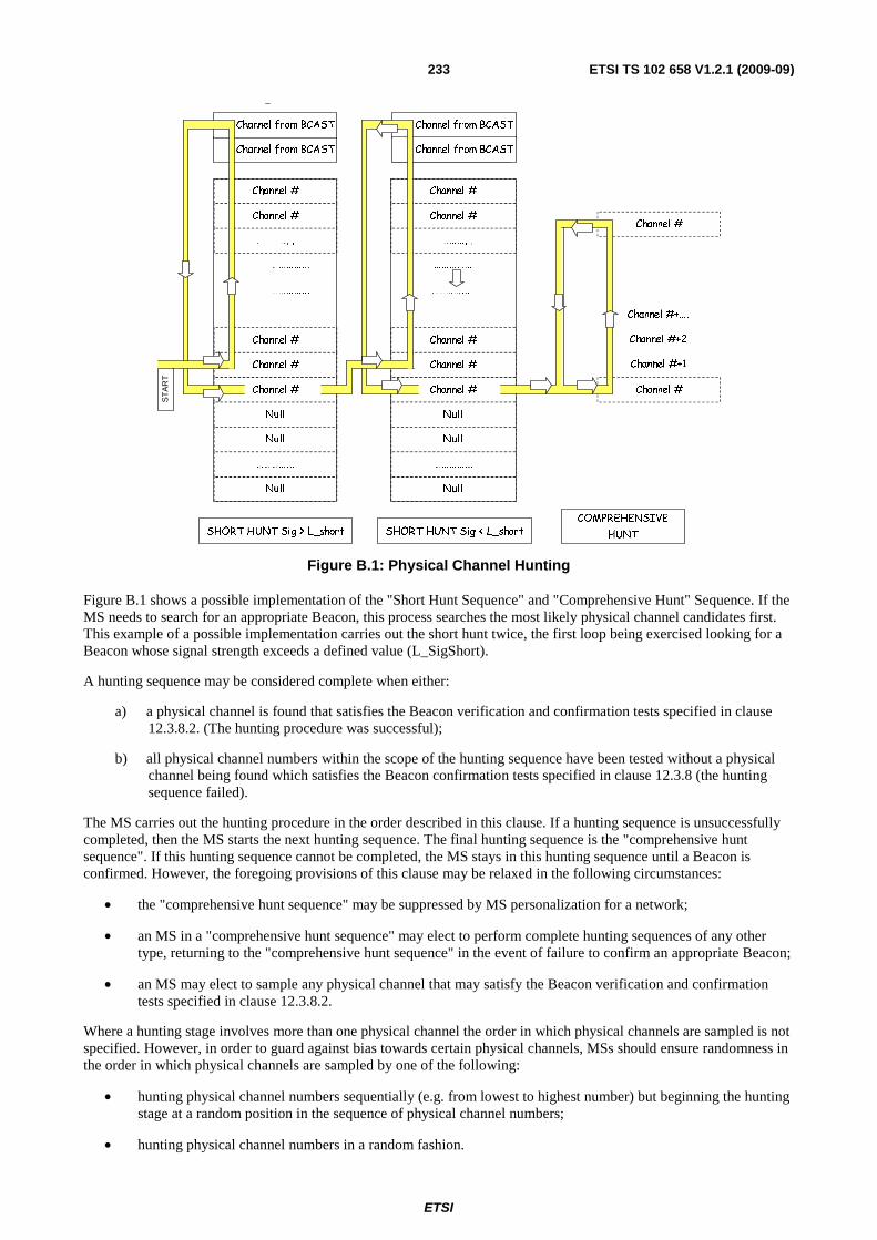
ETSI
ETSI TS 102 658 V1.2.1 (2009-09)233
Channel #+1
Channel #+2
Channel #+….
Channel #
Channel #
Channel #
Null
Null
Channel #
Channel #
Null
…………...
…………...
…………...
…………...
Channel #
Channel #
Channel #
Null
Null
Channel #
Channel #
Null
…………...
…………...
…………...
…………...
Channel #
Channel #
SHORT HUNT Sig < L_shortCOMPREHENSIVE
HUNT
Channel from BCAST
Channel from BCAST
Channel from BCAST
Channel from BCAST
Channel from BCAST
ST
AR
T
SHORT HUNT Sig > L_short
Figure B.1: Physical Channel Hunting
Figure B.1 shows a possible implementation of the "Short Hunt Sequence" and "Comprehensive Hunt" Sequence. If the MS needs to search for an appropriate Beacon, this process searches the most likely physical channel candidates first. This example of a possible implementation carries out the short hunt twice, the first loop being exercised looking for a Beacon whose signal strength exceeds a defined value (L_SigShort).
A hunting sequence may be considered complete when either:
a) a physical channel is found that satisfies the Beacon verification and confirmation tests specified in clause 12.3.8.2. (The hunting procedure was successful);
b) all physical channel numbers within the scope of the hunting sequence have been tested without a physical channel being found which satisfies the Beacon confirmation tests specified in clause 12.3.8 (the hunting sequence failed).
The MS carries out the hunting procedure in the order described in this clause. If a hunting sequence is unsuccessfully completed, then the MS starts the next hunting sequence. The final hunting sequence is the "comprehensive hunt sequence". If this hunting sequence cannot be completed, the MS stays in this hunting sequence until a Beacon is confirmed. However, the foregoing provisions of this clause may be relaxed in the following circumstances:
• the "comprehensive hunt sequence" may be suppressed by MS personalization for a network;
• an MS in a "comprehensive hunt sequence" may elect to perform complete hunting sequences of any other type, returning to the "comprehensive hunt sequence" in the event of failure to confirm an appropriate Beacon;
• an MS may elect to sample any physical channel that may satisfy the Beacon verification and confirmation tests specified in clause 12.3.8.2.
Where a hunting stage involves more than one physical channel the order in which physical channels are sampled is not specified. However, in order to guard against bias towards certain physical channels, MSs should ensure randomness in the order in which physical channels are sampled by one of the following:
• hunting physical channel numbers sequentially (e.g. from lowest to highest number) but beginning the hunting stage at a random position in the sequence of physical channel numbers;
• hunting physical channel numbers in a random fashion.
ETSI
ETSI TS 102 658 V1.2.1 (2009-09)234
The procedures defined in the present document are intended to provide a comprehensive range of methods that may be used as a basis for the design of MSs.
NOTE 2: The specified mechanism is a framework for MSs. The use of additional or differing procedures is not prohibited provided that they satisfy the verification and confirmation procedures defined in the present document.
EXAMPLE: An MS locating a physical channel which satisfies the Beacon confirmation tests specified in clause 12.3.8.2 may continue the hunt in anticipation that an alternative Beacon may be found with a higher received signal quality or level. Also, MSs need not limit the hunting procedures to the receiver sensitivity threshold levels specified and may conduct additional hunts at other levels.
B.1.1 Resuming a Beacon hunt channel When "resuming a Beacon hunt channel" the MS retunes to the logical physical channel number of the Beacon on which it was last confirmed. The MS should be capable of receiving on the Beacon outbound channel, which it is resuming within two framesets of the following instants:
a) the end of any Disconnect_Request Header message, which requires the MS to cease activity on the traffic channel to which it is currently tuned;
b) the end of the last Disconnect_Request Header message sent by the MS on a traffic channel;
c) the end of any Guard message (Guard_Kind=Illegally_Parked received on a traffic channel where either MS ID in the Guard message does NOT match one of the MS IDs from the Goto Channel message that directed the MS to the traffic channel;
d) the operation of the any user initiated "call end request" by the user during a group call when the MS was not the call originator of the call.
Before confirming the Beacon the MS should verify any SYScode received on the channel in accordance with the procedures of clause 12.3.8.2.2.1. In the event of the SYScode fails the verification procedures, the hunting sequence is considered unsuccessfully completed and the MS enters the "short hunt sequence".
B.1.2 Commanded Beacon hunt channel
B.1.2.1 Conditions to enter a Commanded Beacon hunt
A "single channel hunt" applies when the MS is directed to a Beacon other than the one on which it was last confirmed, or when it is switched on whilst still retaining valid network information from previous activity on the selected network, or the user initiates a change of selected network and the MS still retains valid information of previous activity on the new selected network. The MS should be able to receive the nominated physical channel within 3 framesets of the following instants:
a) the end of any valid B_MOVE message that is applicable to the MS;
b) the MS being switched on, provided that the unit holds a valid record of the channel number on which the MS was most recently confirmed;
c) a change of selected network being initiated by the user, provided that the MS holds a valid record of the channel number on which the MS was most recently confirmed on the new selected network.
ETSI
ETSI TS 102 658 V1.2.1 (2009-09)235
B.1.2.2 Nominated Channel for the Single Channel Hunt
The nominated channel is:
a) the logical physical channel number indicated in the CONT information element of the T_CLEAR message; or
b) the channel number indicated in the CONT information element the B_MOVE message; or
c) the channel number held in the MSs read/write storage as the Beacon on which the unit was most recently confirmed on the selected network.
The MS does not make any transmissions on a Beacon until it has confirmed the channel in accordance with the procedure specified in clause 12.3.8.2.2.3. In the event of a failure of the Beacon to meet the channel confirmation criteria the hunting sequence is considered unsuccessfully completed. Upon unsuccessful completion of the "commanded Beacon hunt channel" the MS enters the "short hunt sequence".
B.1.2.3 Short Hunt Sequence
A "Short Hunt Sequence" samples all physical channels most likely to be employed as Beacons by the selected network. There are many strategies that may be employed but all will search from a shortlist of candidates as follows:
a) A list of likely physical channels specified by an external agency will be stored in MS fixed non-volatile storage.
b) The MS may modify the scope of the shortlist of physical channels from information broadcast from the network and held in its non-volatile storage as follows:
1) by adding to the compass of the hunting sequence channel numbers received in B_BCAST (Announce/Withdraw) message from the selected network;
2) by removing from the compass of the hunting sequence channel numbers received in B_BCAST (Announce/Withdraw) messages from the selected network.
One strategy illustrated in figure B.1 entails hunting the list of physical channel numbers sequentially (e.g. from the randomly chosen list position to the highest then circling to the lowest list position) but beginning the hunting stage at a random position in the sequence of physical channel numbers. The shortlist is sampled twice, the first loop being exercised looking for a Beacon whose signal strength exceeds a defined value (L_Short).
Another possible strategy entails hunting the complete shortlist of physical channel numbers sequentially (e.g. from lowest list position to highest list position) recording the signal strength and/or BER. After sampling all channels in the list the MS chooses the most appropriate Beacon.
B.1.2.3.1 Conditions to enter a Short Channel Hunt
An MS enters the "short hunt sequence":
a) immediately after switch-on, provided that the MS holds no valid information of previous activity on the selected network;
b) when the user indicates a change of selected network, provided that the MS holds no valid information of previous activity on the selected network.
The MS may enter the "short hunt sequence" at any time during the "comprehensive hunt sequence", at the MSs discretion.
The MS should not make any transmissions on a Beacon located during the "short hunt sequence" until it has verified and confirmed the channel in accordance with the procedures specified in clause 12.3.8.2.
Upon unsuccessful completion of the "short hunt sequence" the MS enters the "comprehensive hunt sequence", except when the "comprehensive hunt sequence" has been suppressed by MS personalization for a network.
ETSI
ETSI TS 102 658 V1.2.1 (2009-09)236
B.1.2.4 Comprehensive Hunt Sequence
The "comprehensive hunt sequence" includes every channel within the range set by the lowest and highest channel numbers set by the network personalization, held in the MSs fixed non-volatile storage.
B.1.2.4.1 Conditions to enter a Comprehensive Channel Hunt
An MS enters the "comprehensive hunt sequence" when a "short hunt sequence" has been unsuccessfully completed.
An MS may repeat the "comprehensive hunt stage" until such a time as a physical channel which satisfies the Beacon confirmation tests specified in clause 12.3.8.2 is found.
The MS will not make any transmissions on a Beacon located during the "comprehensive hunt sequence" until it has confirmed the channel in accordance with the procedures specified in clause 12.3.8.2.
At any time during the "comprehensive hunt sequence" an MS may undertake a "short hunt sequence", or sample any physical channels that the MS is able to determine may be successful, returning to the "comprehensive hunt sequence" in the event that these choices is unsuccessful.
The possibility to suppress the "comprehensive hunt sequence" by MS network personalization. In this case the MS will remain in the "short hunt sequence" with the acquisition threshold set to a level L_Squelch until such time as a channel which satisfies the Beacon confirmation tests specified in clause 12.3.8.2.
B.1.2.5 Receiver Sensitivity During Beacon Channel Acquisition
The MS should not attempt to become active on any physical channel for which the received signal level (or signal quality) is less than the specified acquisition threshold.
The acquisition threshold L_SHort is set to a signal level within the range L_Upper_SHort to L_Lower_SHort at the input of the receiver (or an equivalent if the receiver measures signal quality).
L_Squelch is set at a level determined by the MS manufacturer which enables unsuitable physical channels to be rejected on which the received signal is inadequate for a suitable grade of service (or an equivalent if the receiver measures signal quality).
NOTE: The MS may be unable to determine the received signal level but may use other methods such as bit error measurements to determine the signal quality.

ETSI
ETSI TS 102 658 V1.2.1 (2009-09)237
History
Document history
V1.1.1 December 2008 Publication
V1.2.1 September 2009 Publication