Embed Size (px)
Citation preview

ETSI TS 103 161-15 V1.1.1 (2011-10)
Access, Terminals, Transmission and Multiplexing (ATTM); Integrated Broadband Cable and Television Networks;
IPCablecom 1.5; Part 15: Analog Trunking for PBX Specification
Technical Specification

ETSI
ETSI TS 103 161-15 V1.1.1 (2011-10)2
Reference DTS/ATTM-003011-15
Keywords access, broadband, cable, IP, multimedia, PSTN
ETSI
650 Route des Lucioles F-06921 Sophia Antipolis Cedex - FRANCE
Tel.: +33 4 92 94 42 00 Fax: +33 4 93 65 47 16
Siret N° 348 623 562 00017 - NAF 742 C
Association à but non lucratif enregistrée à la Sous-Préfecture de Grasse (06) N° 7803/88
Important notice
Individual copies of the present document can be downloaded from: http://www.etsi.org
The present document may be made available in more than one electronic version or in print. In any case of existing or perceived difference in contents between such versions, the reference version is the Portable Document Format (PDF).
In case of dispute, the reference shall be the printing on ETSI printers of the PDF version kept on a specific network drive within ETSI Secretariat.
Users of the present document should be aware that the document may be subject to revision or change of status. Information on the current status of this and other ETSI documents is available at
http://portal.etsi.org/tb/status/status.asp
If you find errors in the present document, please send your comment to one of the following services: http://portal.etsi.org/chaircor/ETSI_support.asp
Copyright Notification
No part may be reproduced except as authorized by written permission. The copyright and the foregoing restriction extend to reproduction in all media.
© European Telecommunications Standards Institute 2011.
All rights reserved.
DECTTM, PLUGTESTSTM, UMTSTM and the ETSI logo are Trade Marks of ETSI registered for the benefit of its Members. 3GPPTM and LTE™ are Trade Marks of ETSI registered for the benefit of its Members and
of the 3GPP Organizational Partners. GSM® and the GSM logo are Trade Marks registered and owned by the GSM Association.
ETSI
ETSI TS 103 161-15 V1.1.1 (2011-10)3
Contents
Intellectual Property Rights ................................................................................................................................ 5
Foreword ............................................................................................................................................................. 5
1 Scope ........................................................................................................................................................ 7
1.1 Introduction and Purpose .................................................................................................................................... 7
1.2 Relation to Other IPCablecom Specifications .................................................................................................... 7
1.3 NCS Package Requirements ............................................................................................................................... 8
2 References ................................................................................................................................................ 8
2.1 Normative references ......................................................................................................................................... 8
2.2 Informative references ........................................................................................................................................ 8
3 Definitions and abbreviations ................................................................................................................... 9
3.1 Definitions .......................................................................................................................................................... 9
3.2 Abbreviations ..................................................................................................................................................... 9
4 Void .......................................................................................................................................................... 9
5 Overview .................................................................................................................................................. 9
5.1 Functional Responsibility ................................................................................................................................... 9
5.2 Physical Endpoint Interface .............................................................................................................................. 10
5.2.1 Loop-Start Line Interface ............................................................................................................................ 10
5.2.2 Ground-Start Line Interface ........................................................................................................................ 10
5.2.3 DID PBX Trunk Interface ........................................................................................................................... 10
5.2.4 E&M ........................................................................................................................................................... 11
5.2.4.1 Two-wire E&M ..................................................................................................................................... 11
5.2.4.2 Four-wire E&M ..................................................................................................................................... 11
5.3 NCS Package Support ...................................................................................................................................... 11
6 Analog Trunking for PBX Functional Requirements ............................................................................. 12
6.1 Endpoint Configuration .................................................................................................................................... 12
6.1.1 Physical Interface Type Configuration ....................................................................................................... 12
6.1.2 PBX Trunk Type Configuration ................................................................................................................. 13
6.1.3 Start of Dialling Method Configuration ...................................................................................................... 13
6.1.4 Out-pulse Dialling Method ......................................................................................................................... 13
6.1.5 Maximum Out-pulsed Dial String Length .................................................................................................. 13
6.1.6 Re-seizure Delay ......................................................................................................................................... 14
6.2 Signalling Support ............................................................................................................................................ 14
6.2.1 Digit and Digit Related Events ................................................................................................................... 15
6.2.2 Digit Events over E&M .............................................................................................................................. 15
6.2.3 Local Tones ................................................................................................................................................ 15
6.2.3.1 Local Tones over E&M ......................................................................................................................... 16
6.2.4 Caller ID and VMWI .................................................................................................................................. 16
6.2.5 Hook Events................................................................................................................................................ 16
6.2.6 Open Signal Interval ................................................................................................................................... 16
6.2.7 Ring Requests ............................................................................................................................................. 17
6.2.8 T1 Trunk Signalling Requirements ............................................................................................................. 17
Annex A (normative): Event Packages ............................................................................................... 18
A.1 IPCablecom Analog Trunking for PBX Package ................................................................................... 18
Annex B (informative): Sample Call Flows .......................................................................................... 22
B.1 CALL SETUP Call Flow Example ........................................................................................................ 22
B.2 CALL TEARDOWN Call Flow Example .............................................................................................. 27
B.3 CALL BLOCK/RELEASE Call Flow Example - Network Initiated ..................................................... 29
B.4 CALL BLOCK/RELEASE Call Flow Example - PBX Initiated ........................................................... 31

ETSI
ETSI TS 103 161-15 V1.1.1 (2011-10)4
Annex C (informative): Bibliography ................................................................................................... 34
History .............................................................................................................................................................. 35

ETSI
ETSI TS 103 161-15 V1.1.1 (2011-10)5
Intellectual Property Rights IPRs essential or potentially essential to the present document may have been declared to ETSI. The information pertaining to these essential IPRs, if any, is publicly available for ETSI members and non-members, and can be found in ETSI SR 000 314: "Intellectual Property Rights (IPRs); Essential, or potentially Essential, IPRs notified to ETSI in respect of ETSI standards", which is available from the ETSI Secretariat. Latest updates are available on the ETSI Web server (http://ipr.etsi.org).
Pursuant to the ETSI IPR Policy, no investigation, including IPR searches, has been carried out by ETSI. No guarantee can be given as to the existence of other IPRs not referenced in ETSI SR 000 314 (or the updates on the ETSI Web server) which are, or may be, or may become, essential to the present document.
Foreword This Technical Specification (TS) has been produced by ETSI Technical Committee Access, Terminals, Transmission and Multiplexing (ATTM).
The present document is part 15 of a multi-part IPCablecom 1.5 deliverable covering the Digital Broadband Cable Access to the Public Telecommunications Network; IP Multimedia Time Critical Services, as identified below:
Part 1: "Overview";
Part 2: "Architectural framework for the delivery of time critical services over Cable Television Networks using Cable Modems";
Part 3: "Audio Codec Requirements for the Provision of Bi-Directional Audio Service over Cable Television Networks using Cable Modems";
Part 4: "Network Call Signalling Protocol";
Part 5: "Dynamic Quality of Service for the Provision of Real Time Services over Cable Television Networks using Cable Modems";
Part 6: "Event Message Specification";
Part 7: "Media Terminal Adapter (MTA Management Information Base (MIB)";
Part 8: "Network Call Signalling (NCS) MIB Requirements";
Part 9: "Security";
Part 10: "Management Information Base (MIB) Framework";
Part 11: "Media terminal adapter (MTA) device provisioning";
Part 12: "Management Event Mechanism";
Part 13: "Trunking Gateway Control Protocol - MGCP option";
Part 14: "Embedded MTA Analog Interface and Powering Specification"
Part 15: "Analog Trunking for PBX Specification";
Part 16: "Signalling for Call Management Server";
Part 17: "CMS Subscriber Provisioning Specification";
Part 18: "Media Terminal Adapter Extension MIB";
Part 19: "IPCablecom Audio Server Protocol Specification - MGCP option";
Part 20: "Management Event MIB Specification";

ETSI
ETSI TS 103 161-15 V1.1.1 (2011-10)6
Part 21: "Signalling Extension MIB Specification".
NOTE 1: Additional parts may be proposed and will be added to the list in future versions.
NOTE 2: The choice of a multi-part format for this deliverable is to facilitate maintenance and future enhancements.

ETSI
ETSI TS 103 161-15 V1.1.1 (2011-10)7
1 Scope
1.1 Introduction and Purpose The present document defines extensions to the IPCablecom Network-based Call Signalling (NCS) [2] protocol to support the following analogue trunking for PBX interfaces on an embedded Voice-Over-IP client device in a IPCablecom environment:
• Ground-start lines.
• PBX one-way and two-way DTMF (dual-tone multi frequency tones) trunks.
As shown in figure 1, the IPCablecom NCS specification [2] already defines the Loop-Start line interface typically used for residential services today. The present document is designed for additional line/trunk interfaces to support analogue trunking for PBX so that the MTA (multimedia terminal adapter) may be used to interface directly to a Legacy PBX via a Ground-Start line or other trunk interface (E&M - E and M Signalling or DID - Direct Inward Dialling). Example PBX trunk interfaces are shown below.
Figure 1: Ground-Start Line and Loop Trunk Interfaces
1.2 Relation to Other IPCablecom Specifications Analog Trunking for PBX is defined here as a supplement to the IPCablecom NCS interface. Though the present document is included as part of the IPCablecom 1.5 release, the features specific to IPCablecom 1.5 are not required to support analogue trunking for PBX. The capabilities defined in the present document may be supported by components that conform to the IPCablecom 1.0 release. Full support for the IPCablecom 1.5 release is recommended for analogue trunking for PBX due to the inclusion of additional features such as [5] and [4].

ETSI
ETSI TS 103 161-15 V1.1.1 (2011-10)8
1.3 NCS Package Requirements The IPCablecom analogue trunking (PAT) for PBX package is defined in the present document as an extension to the NCS Line package to provide the needed functionality specific to analogue trunking for PBX. Both packages are required to support analogue trunking for PBX. It should be noted that the PAT package is designed in such a way as to provide a complete abstraction of the physical characteristics of an endpoint to the Call Agent. For example, the Call Agent is unaware of the physical endpoint interface (e.g. E&M or DID), start of dialling method (e.g. wink start), and out-pulse dialling type (e.g. DTMF). This abstraction exists due to time-to-market considerations. As such, the endpoint is required to alter its behaviour based on these physical characteristics given a particular command from the Call Agent. In some cases this behaviour breaks the general rules of NCS. The exceptions to NCS are documented in this specification and apply only to analogue trunking for PBX.
2 References References are either specific (identified by date of publication and/or edition number or version number) or non-specific. For specific references, only the cited version applies. For non-specific references, the latest version of the reference document (including any amendments) applies.
Referenced documents which are not found to be publicly available in the expected location might be found at http://docbox.etsi.org/Reference.
NOTE: While any hyperlinks included in this clause were valid at the time of publication, ETSI cannot guarantee their long term validity.
2.1 Normative references The following referenced documents are necessary for the application of the present document.
[1] ANSI T1.401: "Network to Customer Installations - Analog Voicegrade Switched Access Lines Using Loop-Start and Ground-Start Signaling".
[2] ETSI TS 103 161-4: "Access, Terminals, Transmission and Multiplexing (ATTM); Integrated Broadband Cable and Television Networks; IPCablecom 1.5; Part 4: Network Call Signalling Protocol".".
[3] TIA-464-C: "Requirements for Private Branch Exchange (PBX) Switching Equipment".
[4] IETF RFC 2833: "RTP Payload for DTMF Digits, Telephony Tones and Telephony Signals", May 2000.
[5] ITU-T Recommendation T.38: "Procedures for real-time group 3 facsimile communication over IP networks", September 2010.
2.2 Informative references The following referenced documents are not necessary for the application of the present document but they assist the user with regard to a particular subject area.
[i.1] Telcordia GR-31-CORE LSSGR, Issue 4: "CLASS Feature: Calling Number Delivery", June 2006.
[i.2] Telcordia GR-1188: "LSSGR CLASS Feature: Calling Name Delivery, Generic Requirements", April 2009.
[i.3] ANSI 0600407: "Network-to-Customer Installation Interfaces - Direct Inward Dialing Analog Voicegrade Switched Access Using Loop Reverse-Battery Signaling", formerly T1.405.
[i.4] Telcordia GR-506: "LSSGR: Signaling for Analog Interfaces", December 2006.

ETSI
ETSI TS 103 161-15 V1.1.1 (2011-10)9
3 Definitions and abbreviations
3.1 Definitions For the purposes of the present document, the terms and definitions following apply:
endpoint: terminal, gateway or Multipoint Conference Unit (MCU)
gateway: devices bridging between the IPCablecom IP Voice Communication world and the PSTN
NOTE: Examples are the Media Gateway, which provides the bearer circuit interfaces to the PSTN and transcodes the media stream, and the Signalling Gateway, which sends and receives circuit switched network signalling to the edge of the IPCablecom network.
trunk: analogue or digital connection from a circuit switch that carries user media content and may carry voice signalling (MF, R2, etc.)
3.2 Abbreviations For the purposes of the present document, the following abbreviations apply:
CAS Channel Associated Signalling CMS Call Management Server DID Direct Inward Dialling DOD Direct Outward Dialling DTMF Dual-tone Multi Frequency (tones) E&M E and M Signalling GS Ground-start LS Loop-start MTA Multimedia Terminal Adapter NCS Network-based Call Signalling PBX Private Branch Exchange PAT IPCablecom Analog Trunking (package) PSTN Public Switched Telephone Network RLCF Reverse Loop Current Feed
4 Void
5 Overview The present document describes the functional requirements for an embedded client to support one-way incoming, one-way outgoing, and two-way PBX trunks. The physical interfaces used to support these trunk types are also defined.
5.1 Functional Responsibility To maintain compliance with the IPCablecom NCS specification [2], the Call Agent will remain responsible for all higher order functionality whenever possible. Only when timing is critical will the endpoint be responsible for the required functionality. For example, the endpoint is expected to out-pulse a string of successive digits when requested by the Call Agent. In this case, the endpoint is responsible for the timing of the duration of each digit and the delay between them.
The endpoint is also responsible for all timing requirements related to the start method in use - wink, delay or immediate. In fact, the start method used by the interface is transparent to the Call Agent.

ETSI
ETSI TS 103 161-15 V1.1.1 (2011-10)10
5.2 Physical Endpoint Interface Various physical interfaces provided by an endpoint of an MTA are used to support the following PBX trunks:
• One-way incoming trunk - supports calls originating from the network towards the PBX via the MTA. A specific example of a one-way incoming trunk is a DID PBX (direct inward dialling private branch exchange) trunk which is to be provided using a DID PBX physical interface.
• One-way outgoing trunk - supports calls originating on the PBX towards the network via the MTA. A specific example of a one-way outgoing trunk is a DOD PBX trunk which may be provided over a number of physical interfaces.
• Two-way trunk - supports calls originating and terminating on the PBX via the MTA. A four-wire E&M physical interface is typically used to support two-way PBX trunks; however, other interfaces may also be used.
The following clauses describe each physical interface that may be provided on an MTA to support one or more of the above defined PBX trunks.
5.2.1 Loop-Start Line Interface
The NCS Line package defined in the IPCablecom NCS specification [2] is used to support loop-start lines. Loop-start lines are typically used for residential voice services, but may be used to support analogue trunking for PBX.
5.2.2 Ground-Start Line Interface
Ground-start signalling interfaces are used to provide two-way service to customer-installation switching systems, e.g. legacy PBX systems.
According to [1] ground-start signalling for two-way dial facilities was introduced to reduce the likelihood of seizure of the line at both ends during the silent interval of the alerting signal. Ground-start signalling is typically used on one-way or two-way seizure PBX lines with Direct Outward Dialling (DOD) and attendant-handled incoming call service. Ground-start lines are also used for automatically originated data service. The two-wire ground-start line conductors transmit common-battery loop supervision, loop dial pulses or DTMF address signals, alerting signals, and voice-band signals. Ground-start lines are often used rather than loop-start lines for the following reasons:
• To avoid simultaneous seizure, i.e. glare conditions.
• To allow the application of a dc voltage between tip and ring and the closure of a path from the tip conductor to ground as a start dial signal.
• To provide a positive indication of network disconnect.
See [1] for the network interface requirements for ground-start access lines.
5.2.3 DID PBX Trunk Interface
A one-way Direct Inward Dialling (DID) trunk interface as described in [3] is required to support a DID interface of a PBX. DID trunks can only make calls in the direction from the network towards the PBX.
Electrically, a DID trunk looks similar to the reverse of a 2-wire loop-start interface. The PBX provides loop current by applying -48 volt battery to the ring lead and grounding the tip lead. The MTA signals off-hook and on-hook towards the PBX by closing and opening the loop. The PBX signals answer supervision (off-hook) by reversing battery and ground on the tip and ring leads [i.3]. The PBX signals call release (on-hook) by restoring battery to ring and ground to tip. Since this is a one-way trunk, there is no ringing voltage as seen on a loop-start interface.
The MTA may dial using either dial-pulse at 10 pulses per second with 300 ms between digits or DTMF at 10 tones per second. Dial-pulse may be done either by opening and closing the loop in a manner similar to loop-start dialling; or it may use battery and ground pulsing. With dial-pulse interfaces, the network typically only dials the last 2 or 3 address digits to minimize call setup delay.

ETSI
ETSI TS 103 161-15 V1.1.1 (2011-10)11
The interface has three methods for start of dialling:
• Immediate start - The MTA starts dial-pulsing shortly after closing the loop indicating off-hook condition. This method cannot be used for DTMF.
• Wink start - The MTA waits for the PBX to signal that it is ready to accept digits. The signal from the PBX is a 200 ms battery reversal (off-hook).
• Delay start - The MTA waits for the PBX to signal that it is ready to accept digits. The signal from the PBX is a battery reversal of at least 100 ms (off-hook) followed by restoration of battery (on-hook) some time later.
Of the three start-of-dialling methods, wink start is most common.
5.2.4 E&M
E&M is described in annex F of [3] and is typically used as a PBX tie trunk. E&M trunks may be configured to be 2-way or 1-way. Signalling may be either dial pulse or DTMF. The interface is extremely simple and only off-hook and on-hook are signalled in each direction. The PBX signals off-hook and on-hook on the M-lead (Mouth) and listens for off-hook and on-hook signals on the E-lead (Ear). The three dialling methods found in DID are also used in E&M.
The interface has three methods for start of dialling:
• Immediate start - The calling side of the interface goes off-hook. It starts dial pulsing shortly afterwards (at least 65 ms). This method cannot be used for DTMF.
• Wink start - The calling side goes off-hook and waits for the called side to signal that it is ready to accept digits. The signal from the called side is a 200 ms off-hook wink.
• Delay start - The calling side goes off-hook and waits for the called side to signal that it is ready to accept digits. The signal from the called side is an off-hook transition within 150 ms of detecting off-hook and lasting at least 140 ms followed by an on-hook some time later.
Answer supervision is transmitted on the called side by a transition to off-hook.
Release supervision is transmitted by a transition to on-hook.
5.2.4.1 Two-wire E&M
Two-wire E&M (or Type I E&M) has two conductors on the interface called the E-lead (or Ear) and the M-lead (or Mouth). The PBX provides -48 volt battery on both leads. The MTA signals off-hook by shorting the PBX E-lead to ground. The PBX signals off-hook by closing a contact to provide battery to the M-lead.
5.2.4.2 Four-wire E&M
Four-wire E&M (Type II E&M) has four conductors called the E-Lead, the M-Lead, Sleeve Battery, and Sleeve Ground. The PBX applies -48 volt battery to the E-Lead and grounds the Sleeve Ground. The MTA provides -48 volt battery on the Sleeve Battery and grounds the M-Lead with a current detector. The MTA signals off-hook by shorting the E-Lead to Sleeve Ground. The PBX signals off-hook by shorting the M-Lead to Sleeve Battery.
5.3 NCS Package Support In order to avoid the unnecessary complexity of supporting redundant signals and events, an additional package above and beyond the NCS Line package is defined here to include only those events and signals that are needed to support analogue trunking for PBX, but do not already exist in the NCS Line package. Due to this design, the PAT package relies heavily on the NCS Line package. In other words, both packages must be supported when providing analogue trunking for PBX.
As shown in table 1 below, support for the NCS Line package is required regardless of the interface type and service provided. Support for the PAT package is required only for analogue trunking for PBX.

ETSI
ETSI TS 103 161-15 V1.1.1 (2011-10)12
6 Analog Trunking for PBX Functional Requirements In general, support for analogue trunking for PBX as defined in the present document is optional, i.e. not required for IPCablecom compliancy. Analog Trunking for PBX is an add-on to existing functionality already defined in other IPCablecom specifications.
Table 1 describes the support required based on the physical interface type. In some cases the configuration parameter does not apply to the particular interface or trunk type. In this case, the parameter is marked as "Not Needed".
Table 1: Interface Requirements Matrix
Interface Type
Trunk Type NCS Package Support
Start of Dialling Method
Out-pulse Dialling Method
Max Length of Out-pulse Dial String Line PAT
Loop-Start Residential voice Yes No Dial tone Not Needed Not Needed 1-way incoming Yes Yes Not Needed Needed Needed 1-way outgoing Yes Yes Dial tone Not Needed Not Needed 2-way Yes Yes Dial tone Needed Needed
Ground-Start 1-way incoming Yes Yes Not Needed Needed Needed 1-way outgoing Yes Yes Dial tone Not Needed Not Needed 2-way Yes Yes Dial tone Needed Needed
DID PBX 1-way incoming Yes Yes Needed Needed Needed E&M 1-way incoming Yes Yes Needed Needed Needed
1-way outgoing Yes Yes Needed Not Needed Not Needed 2-way Yes Yes Needed Needed Needed
T1 1-way incoming Yes Yes Needed1 Needed Needed 1-way outgoing Yes Yes Needed1 Not Needed Not Needed 2-way Yes Yes Needed1 Needed Needed
NOTE: For T1 the start method depends on the physical interface being emulated.
6.1 Endpoint Configuration To support the trunk types defined in clause 5.2, the endpoint must be configured with the following:
• Physical interface type
• PBX Trunk type
• Start of dialling method
• Out-pulse dialling method
• Maximum length of out-pulsed dial string
• Re-seizure delay
6.1.1 Physical Interface Type Configuration
At any given point in time, an endpoint supports one and only one type of interface:
• Loop-start line interface
• Ground-start line interface
• E&M 2-wire line interface
• E&M 4-wire line interface
• DID PBX trunk interface
• T1

ETSI
ETSI TS 103 161-15 V1.1.1 (2011-10)13
The question of how a particular endpoint is configured for a particular interface type is beyond the scope of the present document. For example, the endpoint may be configured via provisioning or separate MTA hardware used to provide the interface requirements defined here. The only point is that an endpoint - once configured - will provide one type of interface.
See clause 5.2 for the interface requirements between the MTA and the PBX.
6.1.2 PBX Trunk Type Configuration
As stated in clause 5.2, the following PBX trunk types are supported:
• One-way incoming trunk
• One-way outgoing trunk
• Two-way trunk
The endpoint must be configured as such when used to interface to a PBX to provide one of the above trunk types. When this configuration information is missing, the default behaviour is to provide residential voice service, which may or may not be applicable to the physical interface (see table 1).
6.1.3 Start of Dialling Method Configuration
In order for the MTA to provide an interface to a PBX using either a PBX DID or E&M physical interface, the start of dialling method must be configured to something other than the default "dial tone" method. The configured start of dialling method for two-way E&M PBX trunks is used in both directions - PBX to endpoint and endpoint to PBX. For loop-start and ground-start lines the default "dial tone" method must be used which indicates that dial tone is provided as a signal to the PBX to start dialling. The start of dialling methods in which the endpoint may be configured are as follows:
• Dial tone (default)
• Immediate start
• Wink start
• Delay start
6.1.4 Out-pulse Dialling Method
When an endpoint is configured to support incoming PBX calls, the endpoint will be expected to out-pulse a dial string towards the PBX. In this case, the endpoint must be configured to out-pulse one of the following digit types:
• DTMF
• Dial Pulse
6.1.5 Maximum Out-pulsed Dial String Length
The Call Agent may provide the entire external phone number of the extension being dialled in the PBX. Typically, however, only the last few digits are needed. As such, the endpoint must be configured with the maximum dial string length when configured to support incoming PBX calls. When the Call Agent provides a dial string that exceeds the maximum length configured, the endpoint must out-pulse only the last digits received up to the configured maximum length. For example, let us say that the maximum out-pulsed dial string length is configured to be four and the Call Agent provides the following dial string to out-pulse:
(1, 7, 7, 0, 5, 5, 5, 1, 2, 1, 2)
The endpoint would out-pulse only the last four digits in this case (1, 2, 1, 2).
The maximum out-pulsed dial string length is limited to 32 digits.

ETSI
ETSI TS 103 161-15 V1.1.1 (2011-10)14
6.1.6 Re-seizure Delay
Due to PBX requirements once a trunk is released it cannot be seized again for a short period of time. The MTA must be configured with the amount of time required to wait (in ms). The default is zero, i.e. no delay. The MTA must not re-seize a trunk during this period of time. If a new Call Setup request is received during this time, the MTA must delay execution of the command until such time has passed. The command must not, however, be rejected due to this requirement.
6.2 Signalling Support In order to help quickly detect configuration issues (e.g. endpoint is configured for residential voice while the Call Agent is configured for PBX service), commands issued to the endpoint that are specific to a particular service must be rejected when the endpoint is configured to support any other service. The reverse is also true. If the endpoint notifies an event that is specific to a service other than its current configuration via the Call Agent, then the Call Agent must reject the NTFY.
When an endpoint is configured for residential voice, independent of the physical interface, support for the PAT package must be suppressed. As such, the endpoint must not include the PAT package in the list of supported packages when audited via the AUEP command. An endpoint that is requested to detect an event or apply a signal that is specific to the PAT package must return an error (error code 518 - unsupported or unknown package).
When an endpoint is configured to be a one-way or two-way PBX trunk, independent of the physical interface, the PAT package must be fully supported. When endpoint capabilities are audited via the AUEP command, the PAT package must be included in the list of supported packages. The default NCS Line package must also be included. If however, the endpoint is requested to detect an event or apply a signal included in the NCS Line package according to table 2 that the interface is unable to support an error must be returned (error code 512 or 513 - not equipped to detect event or generate signal). Some signals/events that are shown to be "not required" are allowed to be requested by the Call Agent. The endpoint must apply the signal or process the event as requested if the endpoint is physically capable of doing so.
NOTE: The T1 physical interface is not listed in table 2. The required signalling support for T1 mirrors the physical interface being emulated.

ETSI
ETSI TS 103 161-15 V1.1.1 (2011-10)15
Table 2: NCS Line Package Support
NCS Line Package Signal / Event
Required for… LS Residential
Voice LS/GS PBX
Trunk E&M PBX Trunk DID PBX Trunk
0-9,*,#,A,B,C,D Yes Yes Yes No bz Yes Yes Yes Yes cf Yes No No No ci(ti, nu, na) Yes No No No dl Yes Yes Yes No ft Yes Yes Yes Yes hd Yes Yes Yes Yes hf Yes Yes Yes Yes hu Yes Yes Yes Yes L Yes Yes Yes No ld Yes Yes Yes Yes ma Yes Yes Yes Yes mt Yes Yes Yes Yes mwi Yes No No No oc Yes Yes Yes Yes of Yes Yes Yes Yes osi Yes No No No ot Yes No No No r0, r1, r2, r3, r4, r5, r6 or r7 Yes No No No rg Yes No No No ro Yes Yes Yes Yes rs Yes No No No rt Yes Yes Yes Yes sl Yes No No No t Yes Yes Yes No TDD Yes Yes Yes Yes vmwi Yes No No No wt1, wt2, wt3, wt4 Yes No No No X Yes Yes Yes No
There are some special considerations related to the use of the NCS Line package with analogue trunking for PBX as detailed in the clauses below.
6.2.1 Digit and Digit Related Events
When the endpoint is expected to receive digits from the PBX and the Call Agent is to be notified of these events, the Call Agent must use the NCS Line package digit (0-9,*,#,A,B,C,D,X) and digit related events (L, t) to request them. The Call Agent may request the processing of digit events in any manor allowed by NCS. For example, the endpoint may be instructed to collect digits according to a supplied Digit Map.
6.2.2 Digit Events over E&M
When an E&M PBX trunk is setup to use a start of dialling method of "immediate start" the Call Agent should take special precautions to insure that digits are not missed from the PBX. The PBX will start dialling after a short delay after going off-hook. This may occur before the Call Agent requests digits from the endpoint after being notified of the off-hook event. There are mechanisms allowed by NCS to guard against this. For example, the endpoint may be instructed to quarantine digits while in this state. This is accomplished by the use of the detectEvents parameter. Another option is to use an embedded request to instruct the endpoint to autonomously collect digits upon off-hook detection. See [2] for more information.
6.2.3 Local Tones
Though only a few local tones (MTA ≥ PBX) are required for analogue trunking for PBX as indicated in table 2, each physical interface should be capable of applying all requested NCS Line package tones towards the PBX. To maintain as much flexibility as possible and to support potential future PBX-like features, the endpoint must apply the requested tones (with noted exceptions below) as per the rules of NCS as long as the endpoint is physically capable of doing so.

ETSI
ETSI TS 103 161-15 V1.1.1 (2011-10)16
6.2.3.1 Local Tones over E&M
Dial tone is not applied over an E&M physical interface. When either dial-tone (L/dl), stutter dial tone (L/sl) or message waiting indicator tone (L/mwi) is requested by the Call Agent to be applied over an E&M interface, the MTA must not apply the tone itself. Instead, the MTA must use the signal request to aid in detecting "no dial" occurrences. As such, the MTA must generate an operation complete event if digits are not detected in time just as it does when dial tone itself is applied (as long as the "keep alive" action is not used in the request).
NOTE: This is simply one example of a timeout signal being stopped by the occurrence of an event. All NCS rules governing the application of a timeout signal is to be followed.
All other local tones, when requested, are applied towards the PBX over an E&M interface.
6.2.4 Caller ID and VMWI
The Caller ID and VMWI NCS Line package signals apply only to LS/GS (loop-start/ground-start) PBX trunk interfaces.
The call setup (PAT/sup) signal defined in the PAT package is used to deliver caller ID information; however, the Call Agent may alternatively use the Line package Caller ID signal to provide caller ID information. Though the PBX typically only expects to receive caller ID information during call setup, the Call Agent may use the Line package Caller ID signal to attempt to display caller ID when the PBX is off-hook (e.g. Caller ID with Call Waiting). To maintain as much flexibility as possible with the use of the NCS Line package the endpoint must honour such a request and attempt to deliver the caller ID information as defined in NCS.
The same is true of VMWI. Though the PBX typically does not expect to receive VMWI information, the Call Agent may use the Line package VMWI signal. To maintain as much flexibility as possible with the use of the NCS Line package the endpoint must honour such a request and attempt to deliver the VMWI information as defined in NCS.
6.2.5 Hook Events
For all physical interface types, the NCS Line package hook events (L/hd, L/hf, L/hu) are used to indicate hook state at the PBX.
For LS/GS, hook events are detected and generated as defined in NCS.
Similarly, for E&M, on-hook and off-hook events are generated when the corresponding signal is detected from the PBX. Based on timing, a flash-hook event may also be generated.
For DID battery reversal is considered to be an off-hook signal from the PBX. Likewise, the transition from reversed to normal battery is considered an on-hook signal. Battery removal is also considered to be an off-hook signal from the PBX. The transition from no battery to battery being detected is considered to be an on-hook signal. Based on the timing of the battery events, e.g. battery removal followed by battery restoration, a flash-hook event may also be signalled by the PBX. The endpoint must generate the corresponding NCS Line package hook events.
NOTE: A PBX uses an off-hook signal to block further calls from being initiated on the trunk.
For T1, in addition to the emulated on-hook and off-hook events, a red alarm condition indicates that no further calls may be processed; however, an off-hook event must not be generated when this condition occurs. Instead the endpoint must be taken out of service and an RSIP Forced must be sent to the Call Agent.
6.2.6 Open Signal Interval
For loop-start lines the L/osi NCS Line package signal is used as a trigger for the endpoint to perform a "timed disconnect release". For ground-start lines, the signal is used as a trigger for the endpoint to provide a "guard release" which has similar characteristics to the loop-start "timed disconnect release". This signal is defined in [i.4] in general terms as an "open signal interval" for both loop-start and ground-start interfaces.

ETSI
ETSI TS 103 161-15 V1.1.1 (2011-10)17
For all PBX trunks, the PAT/rel signal is used as a trigger for the PBX to release the call. For LS/GS the semantics are identical to the L/osi signal. In order to maintain the concept of a physical layer abstraction to the Call Agent and to provide the increased flexibility of the L/osi signal for LS/GS, the L/osi signal is further defined to be identical to the PAT/rel signal for E&M and DID physical interfaces which results in an on-hook from the endpoint. As such, the L/osi signal may be used by the CMS (call management server) as an alternative for PAT/rel for all physical interface types.
For GS/LS the Call Agent may adjust the OSI interval using the L/osi signal parameterized with the "to" parameter, e.g. L/osi(to=800). For E&M and DID, however, the "to" parameter has no effect and, if provided, must be ignored.
6.2.7 Ring Requests
The ring NCS Line package signal requests only apply to LS/GS trunks.
The call setup (PAT/sup) signal defined in the PAT package is used as a trigger to seize the trunk by applying standard ringing; however, the Call Agent may alternatively use the Line package RG signal to provide ringing. Though the PBX typically only expects to receive standard ringing, the Call Agent may request other defined the Line package ring signals (R0 - R7, RS) to seize the trunk. To maintain as much flexibility as possible with the use of the NCS Line package the endpoint must honour such a request and attempt to seize the trunk using the defined ring signal.
6.2.8 T1 Trunk Signalling Requirements
T1 is a digital trunk interface. As such, the signalling between the MTA and PBX required to support one-way incoming, one-way outgoing and two-way PBX trunks is emulated using Channel Associated Signalling (CAS). The signalling between the MTA and Call Agent, however, remains unchanged. In other words, the fact that the physical interface is emulated digitally is of no consequence to the Call Agent.

ETSI
ETSI TS 103 161-15 V1.1.1 (2011-10)18
Annex A (normative): Event Packages This clause defines a set of event packages for the various types of endpoints currently defined by IPCablecom for embedded clients.
Each package defines a package name for the package and event codes and definitions for each of the events in the package. In the tables of events/signals for each package, there are five columns:
Code The package unique event code used for the event/signal.
Description A short description of the event/signal.
Event A check mark appears in this column if the event can be Requested by the Call Agent. Alternatively, one or more of the following symbols may appear:
"P" indicating that the event is persistent,
"S" indicating that the event is an event-state that may be audited,
"C" indicating that the event/signal may be detected/applied on a connection.
Signal If nothing appears in this column for an event, then the event cannot be signalled on command by the Call Agent. Otherwise, the following symbols identify the type of event:
"OO" On/Off signal. The signal is turned on until commanded by the Call Agent to turn it off, and vice versa.
"TO" Timeout signal. The signal lasts for a given duration unless it is superseded by a new signal. Default time-out values are supplied. A value of zero indicates that the time-out period is infinite. The provisioning process may alter these default values.
"BR" Brief signal. The event has a short, known duration.
Additional info Provides additional information about the event/signal, e.g. the default duration of TO signals.
Unless otherwise stated, all events are detected on endpoints. Likewise, unless otherwise stated, all signals are applied onto endpoints. When the application of a signal onto an endpoint results in the generation of audio, the audio is not forwarded onto any connection residing on the endpoint. However, when the signal is applied to a connection, the audio generated by will be forwarded onto the associated connection irrespective of the connection mode.
A.1 IPCablecom Analog Trunking for PBX Package Package name: PAT
The codes listed in table A.1 are used to identify events and signals for the "IPCablecom Analog Trunking for PBX" package for "analogue access lines". This package provides missing functionality from the NCS Line package required to support analogue trunking for PBX and, therefore, must be used in conjunction with the NCS Line package.
Table A.1: PAT Package Codes for Events and Signals
Code Description Event Signal Additional Info ans Call Answer BR bl Call Block OO oc Operation
Complete √ -
of Operation Failure
√ -
rel Release Call BR sup(addr, ti, nu, na) Call Setup TO Time-out = infinite

ETSI
ETSI TS 103 161-15 V1.1.1 (2011-10)19
The definition of the individual events and signals are as follows:
Call answer (ans): A signal indicating that the far end has answered. For loop-start and ground-start PBX trunks a Reverse Loop Current Feed (RLCF) condition is applied as defined in [i.4]. For E&M PBX trunks, an off-hook signal is applied which indicates that the call has been answered and that cut-through has been established.
When the call is answered at the PBX an off-hook event is generated as defined in the NCS Line package. This is applicable to all interface types except DID.
Call block (bl): Depending on the physical interface, this is either a battery removal or a steady off-hook signal typically applied to one-way outgoing trunks (PBX � endpoint), but may be applied to one-way incoming and two-way PBX trunks to indicate that no further calls will be accepted. Call block is enabled via the Call Agent by using either "bl" or "bl(+)". The blocked condition remains in effect until disabled via the Call Agent by using "bl(-)". As with other signals of this type, the call block state does not survive a reset.
In the case of DID, an off-hook is not applied towards the PBX. Instead, the endpoint is simply marked as "blocked" internally. Regardless of the physical interface or trunk type, subsequent call setup requests must be rejected using error code 513 - not equipped to generate signal.
NOTE 1: In this case that the error condition is not permanent. The Call Agent should correct the condition when it finds an endpoint unintentionally left in the "blocked" state. One way to detect such a condition before a call setup is attempted is to audit active signals on the endpoint.
NOTE 2: A PBX may also block a trunk by either going off-hook (LS/GS/E&M) or removing battery (DID). When the PBX goes off-hook to block a trunk, the off-hook event defined in the NCS Line package is generated.
Operation complete (oc): The operation complete event is generated when the gateway was asked to apply one or several signals of type TO on the endpoint, and one or more of those signals completed without being stopped by the detection of a requested event such as off-hook transition or dialled digit. The completion report may carry as a parameter the name of the signal that came to the end of its live time, as in:
O: PAT/oc(PAT/sup)
When the operation complete event is requested, it cannot be parameterized with any event parameters.
NOTE 3: When requested with the "sup" signal (out-pulsing - a TO event), the operation complete event will indicate when out-pulsing is complete.
Operation failure (of): In general, the operation failure event may be generated when the endpoint was asked to apply one or several signals of type TO on the endpoint, and one or more of those signals failed prior to timing out. The completion report may carry as a parameter the name of the signal that failed, as in:
O: PAT/of(PAT/sup)
When the operation failure event is requested, event parameters can not be specified.
Release call (rel): A "rel" signal sent by the Call Agent to the MTA is a request to release all of the resources associated with the telephony leg of the call. As a result of a "rel" signal, the MTA will respond with an "on-hook" event defined in the NCS Line package, whenever the resources have been released. Releasing resources associated with the telephony leg of the call does not affect existing connections (network legs). It 1s up to the Call Agent to send the appropriate delete connection commands in order to release any network connections to that endpoint.
For loop-start PBX trunks the "rel" signal results in a "timed disconnect release" which is identical to the OSI signal defined in NCS. For ground-start PBX trunks the "rel" signal results in a tip-ground release which is also considered to be an open signal interval
For E&M and DID PBX trunks the "rel" signal results in on on-hook being applied towards the PBX
The endpoint generates an "on-hook" event defined in the NCS Line package whenever a call is released as a result of an on-hook event from an originating end of a call (normal release) or due to an abnormal event that resulted in releasing the call. It is always up to the Call Agent to release the call (by sending the "rel" signal) for the terminating end of a call.
Following are two scenarios to demonstrate the use of the "rel" signal.

ETSI
ETSI TS 103 161-15 V1.1.1 (2011-10)20
PBX goes on-hook first: when the PBX goes on-hook, the on-hook event is generated and is typically notified to the Call Agent. The Call Agent will respond at some point in time with the "rel" signal. This signal has no affect in this case for LS/GS trunks since the call has already been released. For E&M/DID, however, the endpoint goes on-hook.
Network goes on-hook first: when the network side goes on-hook, the CMS will respond at some point in time with the "rel" signal. The endpoint will provide the signal as defined above towards the PBX. Some time later the PBX will go on-hook. The on-hook is detected by the endpoint and is processed accordingly.
Call Setup (sup(address, time, number, name)): This signal is used for incoming call setup (endpoint to PBX). An "off-hook" event as defined in the NCS Line package is used to indicate when an outgoing call arrives (corresponding to the outgoing off-hook event).
On an incoming trunk, the "sup" signal is used to seize a trunk and possibly out-pulse digits and/or caller ID information. For LS/GS trunks standard ringing is applied to seize the trunk.
Although a time-out signal, call setup time-out must be infinite. The endpoint must generate either a PAT/oc (for success) or PAT/of (for failure) event to signify its completion. The PAT/oc event must occur upon successful completion of out-pulsing of the last stage of information, otherwise PAT/of event must occur. The "sup" signal is parameterized with the following comma separated list of parameters sup(address, time, number, name). As shown in table A.2, depending on the physical interface, some of the parameters are either optional or ignored when provided. In any case, when these parameters are missing from the request each of the commas will always be included.
Table A.2: Call Setup Parameters
Interface Type Address Time Number Name LS or GS Ignored Optional Optional Optional E&M or DID Mandatory Ignored Optional Ignored
The four parameters of the "sup" signal are defined below:
The address parameter is coded as an ASCII character string of decimal digits that identify the destination number. White spaces are permitted if the string is quoted, however they will be ignored. For LS/GS trunks the address parameter, if provided, must be ignored. For E&M/DID trunks this parameter must be present. In this case the command containing the "sup" signal must be rejected if the address parameter is not present. To maintain the physical layer abstraction, it is RECOMMENDED that the Call Agent always provide the address parameter.
• The time parameter contains the calling timestamp and is coded as "MM/DD/HH/MM", where the first MM is a two-digit value for Month between 01 and 12, DD is a two-digit value for Day between 1 and 31, and Hour and Minute are two-digit values coded according to military local time, e.g. 00 is midnight, 01 is 1 a.m., and 13 is 1 p.m. For E&M/DID trunks the time parameter, if provided, must be ignored.
• The number parameter is coded as an ASCII character string of decimal digits that identify the calling line number. White spaces are permitted if the string is quoted, however they will be ignored.
• The name parameter is coded as a string of ASCII characters that identify the calling line name. White spaces, commas, and parentheses are permitted if the string is quoted. For E&M/DID trunks the name parameter, if provided, must be ignored.
See [i.2] and [i.1] for more information on the caller ID parameters of the "sup" signal.
As shown above, caller ID information may be supplied to the endpoint via the "sup" signal. Only the fields relevant to the physical interface are used. The rest are ignored. For LS/GS trunks, full caller ID information may be delivered. For E&M and DID trunks, however, only the caller ID number is delivered as shown in table A.3.
When the "sup" signal is requested and Caller ID information is not present, the operation complete event is generated after the last destination address digit is out-pulsed as described above. If the destination address parameter is either excluded from the "sup" signal request or ignored, then the operation complete event is generated after the PBX goes off-hook. This is applicable only to LS/GS trunks. For E&M/DID the destination address must be provided.
The following table shows some interactions between the MTA and the PBX for single stage out-pulsing applications (i.e. "sup" signal with <addr> field present in command only).

ETSI
ETSI TS 103 161-15 V1.1.1 (2011-10)21
Table A.3: PBX Sequencing during Call Setup (single stage)
Interface Type Setup Interactions Wink start sup(address, , , ) MTA off-hook � PBX
MTA � wink PBX MTA address � PBX
Immediate start sup(address, , , ) MTA off-hook � PBX MTA address � PBX
An example Call Setup signal using DTMF digits is as follows:
PAT/sup(5551234, , , )
Table A.4 shows an example of multi-stage signalling (i.e. both caller ID number and address parameters present in command). There are many variations of caller ID delivery to a PBX and most are specific to the PBX itself. The example in table A.4 is only one variation. The MTA may need to be configured with the caller ID delivery method if it supports more than one.
Table A.4: PBX Sequencing during Call Setup (multi-stage)
Setup Interactions sup(address, , number, ) MTA off-hook � PBX
MTA � wink PBX MTA number � PBX MTA address � PBX
In either case the off-hook event defined in the NCS Line package is an indication of off-hook from the far end (the other end answered).

ETSI
ETSI TS 103 161-15 V1.1.1 (2011-10)22
Annex B (informative): Sample Call Flows Sample call flows are provided below to demonstrate call setup, call teardown, and call block/release. In order to show both variations of call setup - PBX initiated and network initiated - the call is originated on one PBX and terminated on another. The same is true of the call teardown example. The call, prior to teardown, is setup between two separate PBX's which in essence shows both variations of call teardown - PBX initiated and network initiated.
For simplicity only one Call Agent is used in all call flow examples below since intra Call Agent communications is beyond the scope of the present document.
B.1 CALL SETUP Call Flow Example In the following example call flow, the call is originated on PBX-o which uses either a one-way outgoing or two-way PBX trunk connected to an endpoint on either an MTA or Media Gateway and is denoted as EP-o. The call is terminated on PBX-t which is connected to another MTA or Media Gateway using either a one-way incoming or two-way PBX trunk and is denoted as EP-t.
------------------------------------------------------------------------ | #| PBX-o | EP-o | CA | EP-t | PBX-t | |==|===========|=============|===============|=============|===========| | 1| off-hook|-> | | | | | 2| | NTFY(hd)|-> | | | | 3| | <-|200 | | | | 4| | <-|RQNT(dl,digits)| | | | 5| | 200|-> | | | | 6| <-|start dial | | | | | 7| digits|-> | | | | | 8| | NTFY(digits)|-> | | | | 9| | <-|200 | | | |10| | <-|RQNT(rt,hu) | | | |11| | 200|-> | | | |12| <-|ring back | | | | |13| | <-|CRCX | | | |14| | 200 (sdp-o)|-> | | | |--|-----------|-------------|---------------|-------------|-----------| |15| | |RQNT(sup,oc,of)|-> | | |16| | | <-|200 | | |17| | | | call setup|-> | |18| | | | <-|setup ack | |19| | | | address/cid|-> | |20| | | <-|NTFY(oc(sup))| | |21| | | 200|-> | | |22| | | RQNT(hd)|-> | | |23| | | <-|200 | | |24| | | | <-|off-hook | |25| | | <-|NTFY(hd) | | |26| | | 200|-> | | |27| | | RQNT(hu)|-> | | |28| | | <-|200 | | |29| | | CRCX(sdp-o)|-> | | |30| | | <-|200 (sdp-t) | | |--|-----------|-------------|---------------|-------------|-----------| |31| | <-|MDCX(sdp-t) | | | |32| | 200|-> | | | |33| | <-|RQNT(ans) | | | |34| | 200|-> | | | |35| <-|answer sup. | | | |
Step 1:
A user behind PBX-o goes off-hook and dials "9", for example, to seize an outside line. PBX-o signals off-hook towards EP-o to seize an available trunk.

ETSI
ETSI TS 103 161-15 V1.1.1 (2011-10)23
Step 2:
The off-hook event is notified to the Call Agent.
NTFY 6 aaln/[email protected] MGCP 1.0 NCS 1.0
X: 36
O: hd
Step 3:
The Call Agent acknowledges the NTFY.
200 6 OK
Step 4:
The Call Agent sends an RQNT to play dial tone and request digits according to the supplied digit map.
RQNT 41 aaln/[email protected] MGCP 1.0 NCS 1.0
X: 37
D: (xxxxxxx|x.[T#])
R: hu, [0-9*#T](D)
S: dl
Step 5:
EP-o acknowledges the RQNT.
200 41 OK
Step 6:
EP-o applies the start of dialling signal. For LS and GS dial tone is applied. For E&M, start of dialling is signalled according to the start of dialling method configured. For wink start a 200 ms off-hook wink is applied towards the PBX. For delay start a 140 ms off-hook signal is generated. The dial tone requested in step 4 above is not applied, but a timer is set at this point based on the configuration for default dial tone timeout. An "operation complete" event is generated if digits are not detected in time.
Step 7:
EP-o collects the digits generated by PBX-o.
Step 8:
The digits collected in step 7 trigger a match in the digit map. EP-o sends a NTFY to the Call Agent.
NTFY 7 aaln/[email protected] MGCP 1.0 NCS 1.0
X: 37
O: 5,5,5,1,2,1,2
Step 9:
The Call Agent acknowledges the NTFY.
200 7 OK
Step 10:
The Call Agent sends an RQNT to play ring back tone and requests notification of on-hook.
RQNT 42 aaln/[email protected] MGCP 1.0 NCS 1.0
ETSI
ETSI TS 103 161-15 V1.1.1 (2011-10)24
X: 38
R: hu
S: rt
Step 11:
EP-o acknowledges the RQNT.
200 42 OK
Step 12:
EP-o applies ring back tone towards PBX-o.
Step 13:
The Call Agent creates a connection on EP-o.
CRCX 43 aaln/[email protected] MGCP 1.0 NCS 1.0
C: 51005E4E0003A9ED1700
M: inactive
L: mp:20, a:PCMU
Step 14:
EP-o creates the connection, acknowledges the CRCX and returns its SDP.
200 43 OK
I: 3
<sdp-o>
Step 15:
The Call Agent requests call setup on EP-t by sending an RQNT with PAT/sup.
RQNT 44 aaln/[email protected] MGCP 1.0 NCS 1.0
X: 39
R: hd, PAT/oc, PAT/of
S: PAT/sup(5551212, 02/13/06/59, 5551313, "John Doe")
Step 16:
EP-t acknowledges the RQNT.
200 44 OK
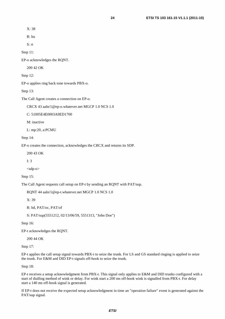
Step 17:
EP-t applies the call setup signal towards PBX-t to seize the trunk. For LS and GS standard ringing is applied to seize the trunk. For E&M and DID EP-t signals off-hook to seize the trunk.
Step 18:
EP-t receives a setup acknowledgment from PBX-t. This signal only applies to E&M and DID trunks configured with a start of dialling method of wink or delay. For wink start a 200 ms off-hook wink is signalled from PBX-t. For delay start a 140 ms off-hook signal is generated.
If EP-t does not receive the expected setup acknowledgment in time an "operation failure" event is generated against the PAT/sup signal.
ETSI
ETSI TS 103 161-15 V1.1.1 (2011-10)25
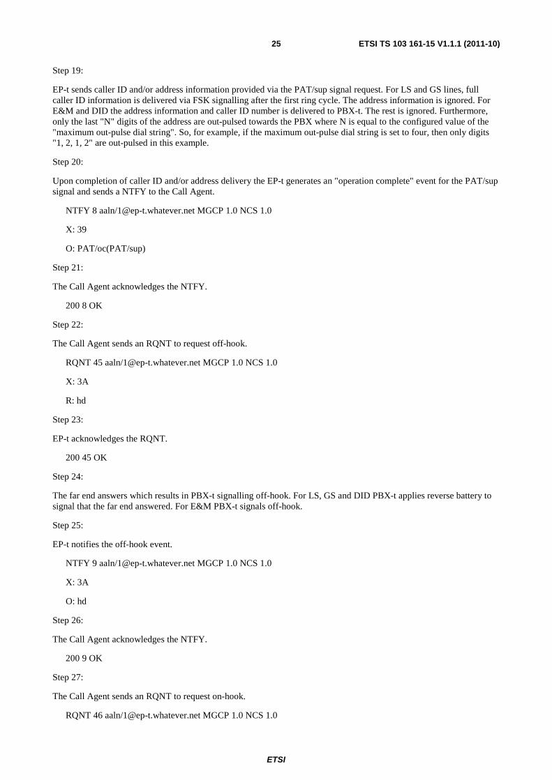
Step 19:
EP-t sends caller ID and/or address information provided via the PAT/sup signal request. For LS and GS lines, full caller ID information is delivered via FSK signalling after the first ring cycle. The address information is ignored. For E&M and DID the address information and caller ID number is delivered to PBX-t. The rest is ignored. Furthermore, only the last "N" digits of the address are out-pulsed towards the PBX where N is equal to the configured value of the "maximum out-pulse dial string". So, for example, if the maximum out-pulse dial string is set to four, then only digits "1, 2, 1, 2" are out-pulsed in this example.
Step 20:
Upon completion of caller ID and/or address delivery the EP-t generates an "operation complete" event for the PAT/sup signal and sends a NTFY to the Call Agent.
NTFY 8 aaln/[email protected] MGCP 1.0 NCS 1.0
X: 39
O: PAT/oc(PAT/sup)
Step 21:
The Call Agent acknowledges the NTFY.
200 8 OK
Step 22:
The Call Agent sends an RQNT to request off-hook.
RQNT 45 aaln/[email protected] MGCP 1.0 NCS 1.0
X: 3A
R: hd
Step 23:
EP-t acknowledges the RQNT.
200 45 OK
Step 24:
The far end answers which results in PBX-t signalling off-hook. For LS, GS and DID PBX-t applies reverse battery to signal that the far end answered. For E&M PBX-t signals off-hook.
Step 25:
EP-t notifies the off-hook event.
NTFY 9 aaln/[email protected] MGCP 1.0 NCS 1.0
X: 3A
O: hd
Step 26:
The Call Agent acknowledges the NTFY.
200 9 OK
Step 27:
The Call Agent sends an RQNT to request on-hook.
RQNT 46 aaln/[email protected] MGCP 1.0 NCS 1.0

ETSI
ETSI TS 103 161-15 V1.1.1 (2011-10)26
X: 3B
R: hu
Step 28:
EP-t acknowledges the RQNT.
200 46 OK
Step 29:
The Call Agent creates a connection on EP-t which includes sdp-o.
CRCX 47 aaln/[email protected] MGCP 1.0 NCS 1.0
C: 51005E4E0003A9ED1700
M: sendrecv
L: mp:20, a:PCMU
<sdp-o>
Step 30:
EP-t acknowledges the CRCX and returns its SDP.
200 47 OK
I: 4
<sdp-t>
Step 31:
The Call Agent modifies the connection on EP-o to send-receive.
MDCX 48 aaln/[email protected] MGCP 1.0 NCS 1.0
C: 51005E4E0003A9ED1700
I: 3
M: sendrecv
Step: 31:
EP-o acknowledges the MDCX.
200 48 OK
Step 32:
The Call Agent sends an RQNT to EP-o to apply answer supervision.
RQNT 49 aaln/[email protected] MGCP 1.0 NCS 1.0
X: 3C
R: hu
S: PAT/ans
Step 33:
EP-o acknowledges the RQNT.
200 49 OK

ETSI
ETSI TS 103 161-15 V1.1.1 (2011-10)27
Step 34:
EP-o applies answer supervision towards PBX-o. For LS and GS EP-o applies reverse battery.
For E&M EP-o applies off-hook. At this point the call is fully established.
B.2 CALL TEARDOWN Call Flow Example In the following example call flow, PBX-o is connected to either an MTA or Media Gateway via a one-way or two-way PBX trunk. The endpoint is denoted as EP-o. PBX-t is connected to either an MTA or Media Gateway via a one-way or two-way PBX trunk. The endpoint is denoted as EP-t. A call is fully established between PBX-o and PBX-t.
------------------------------------------------------------------------ | #| PBX-o | EP-o | CA | EP-t | PBX-t | |==|===========|=============|===============|=============|===========| | 1| on-hook|-> | | | | | 2| | NTFY(hu)|-> | | | | 3| | 200|-> | | | | 4| | <-|DLCX | | | | 5| | 250|-> | | | | 6| | <-|RQNT(rel) | | | | 7| | 200|-> | | | | 8| <-|release | | | | |--|-----------|-------------|---------------|-------------|-----------| | 9| | | RQNT(rel)|-> | | |10| | | <-|200 | | |11| | | | release|-> | |12| | | | <-|on-hook | |13| | | <-|NTFY(hu) | | |14| | | 200|-> | | |15| | | DLCX|-> | | |16| | | <-|250 | | |17| | | RQNT(hd)|-> | | |18| | | <-|200 | |
Step 1:
PBX-o signals on-hook to EP-o. For DID normal battery is applied from PBX-o to signal on-hook.
Step 2:
EP-o notifies the on-hook event.
NTFY 10 aaln/[email protected] MGCP 1.0 NCS 1.0
X: 3C
O: hu
Step 3:
The Call Agent acknowledges the NTFY.
200 10 OK
Step 4:
The Call Agent deletes the connection on EP-o.
DLCX 50 aaln/[email protected] MGCP 1.0 NCS 1.0
C: 51005E4E0003A9ED1700
I: 3
Step 5:
EP-o acknowledges the DLCX.

ETSI
ETSI TS 103 161-15 V1.1.1 (2011-10)28
250 50 OK
P: PS=110, OS=110, PR=110, OR=110, PL=0, JI=0, LA=0, PC/RCS=110, PC/ROS=110, PC/RPL=0, PC/RJI=0
Step 6:
The Call Agents sends an RQNT to EP-o to release the resources to PBX-o.
RQNT 51 aaln/[email protected] MGCP 1.0 NCS 1.0
X: 3D
R: hd
S: PAT/rel
NOTE 1: The Call Agent may also use S: osi to signal call release.
Step 7:
EP-o acknowledges the RQNT.
200 51 OK
Step 8:
EP-o signals a release towards PBX-o to allow the PBX to release internal resources. For LS and GS normal battery is applied. For E&M and DID an on-hook signal is applied.
Step 9:
The Call Agent sends an RQNT to EP-t to release the call.
RQNT 52 aaln/[email protected] MGCP 1.0 NCS 1.0
X: 3E
R: hu
S: PAT/rel
NOTE 2: The Call agent may also use S: osi to signal call release.
Step 10:
EP-t acknowledges the RQNT.
200 52 OK
Step 11:
EP-t signals a release towards PBX-t to indicate that the far end has disconnected. For LS and GS EP-t applies forward disconnect (OSI) for a default duration of 900 ms. For E&M and DID an on-hook signal is applied.
Step 12:
PBX-t signals on-hook. For DID normal battery is applied from PBX-t.
Step 13:
EP-t notifies the on-hook event to the Call Agent.
NTFY 11 aaln/[email protected] MGCP 1.0 NCS 1.0
X: 3E
O: hu
ETSI
ETSI TS 103 161-15 V1.1.1 (2011-10)29
Step 14:
The Call Agent acknowledges the NTFY.
200 11 OK
Step 15:
The Call Agent deletes the connection on EP-t.
DLCX 53 aaln/[email protected] MGCP 1.0 NCS 1.0
C: 51005E4E0003A9ED1700
I: 4
Step 16:
EP-o acknowledges the DLCX.
250 53 OK
P: PS=110, OS=110, PR=110, OR=110, PL=0, JI=0, LA=0, PC/RCS=110, PC/ROS=110, PC/RPL=0, PC/RJI=0
Step 17:
The Call Agent sends an RQNT for off-hook.
Step 18:
RQNT 54 aaln/[email protected] MGCP 1.0 NCS 1.0
X: 3F
R: hd
Step 19:
EP-t acknowledges the RQNT.
200 54 OK
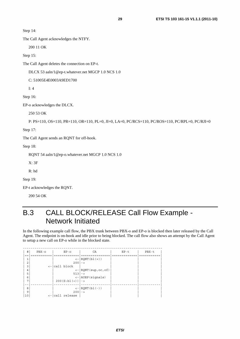
B.3 CALL BLOCK/RELEASE Call Flow Example - Network Initiated
In the following example call flow, the PBX trunk between PBX-o and EP-o is blocked then later released by the Call Agent. The endpoint is on-hook and idle prior to being blocked. The call flow also shows an attempt by the Call Agent to setup a new call on EP-o while in the blocked state.
------------------------------------------------------------------------ | #| PBX-o | EP-o | CA | EP-t | PBX-t | |==|===========|=============|===============|=============|===========| | 1| | <-|RQNT(bl(+)) | | | | 2| | 200|-> | | | | 3| <-|call block | | | | | 4| | <-|RQNT(sup,oc,of)| | | | 5| | 513|-> | | | | 6| | <-|AUEP(signals) | | | | 7| | 200(S:bl(+))|-> | | | |--|-----------|-------------|---------------|-------------|-----------| | 8| | <-|RQNT(bl(-)) | | | | 9| | 200|-> | | | |10| <-|call release | | | |

ETSI
ETSI TS 103 161-15 V1.1.1 (2011-10)30
Step 1:
The Call Agent sends an RQNT to EP-o to block PBX-o from initiating further calls on the trunk.
RQNT 55 aaln/[email protected] MGCP 1.0 NCS 1.0
X: 40
R: hd
S: PAT/bl(+)
Step 2:
EP-o acknowledges the RQNT.
200 55 OK
Step 3:
EP-o signals call block towards PBX-o. For LS and GS battery is removed by EP-o. For E&M a steady off-hook signal is applied. For DID the internal state of EP-o is set to "blocked" only.
Step 4:
The Call Agents attempts call setup by sending an RQNT with the PAT/sup signal.
RQNT 56 aaln/[email protected] MGCP 1.0 NCS 1.0
X: 41
R: hd, PAT/oc, PAT/of
S: PAT/sup(5551212, 02/13/06/59, 5551313, "John Doe")
Step 5:
EP-o sends error code 513 to the Call Agent since the call setup can not be executed at this time.
513 56 Not Equipped to Apply Signal (Endpoint Blocked)
Step 6:
The Call Agent sends an EUEP to EP-o to audit active signals.
AUEP 57 aaln/[email protected] MGCP 1.0 NCS 1.0
F: S
Step 7:
EP-o responds to the AUEP message indicating that the endpoint is blocked.
200 57 OK
S: PAT/bl(+)
Step 8:
The Call Agents sends an RQNT to EP-o to release the blocked condition.
RQNT 58 aaln/[email protected] MGCP 1.0 NCS 1.0
X: 42
R: hd
S: PAT/bl(-)

ETSI
ETSI TS 103 161-15 V1.1.1 (2011-10)31
Step 9:
EP-o acknowledges the RQNT.
200 58 OK
Step 10:
EP-o releases the blocked condition. For LS and GS EP-o applies battery. For E&M EP-o goes on-hook. For DID the internal state is changed to normal (from blocked).
B.4 CALL BLOCK/RELEASE Call Flow Example - PBX Initiated
In the following example call flow, the PBX trunk between PBX-o and EP-o is blocked then later released by the PBX. The endpoint is on-hook and idle prior to being blocked. The call flow also shows an attempt by the Call Agent to setup a new call on EP-o while in the blocked state.
------------------------------------------------------------------------ | #| PBX-o | EP-o | CA | EP-t | PBX-t | |==|===========|=============|===============|=============|===========| | 1| off-hook|-> | | | | | 2| | NTFY(hd)|-> | | | | 3| | <-|200 | | | | 4| | <-|RQNT(dl,digits)| | | | 5| | 200|-> | | | | 6| <-|start dial | | | | | 7|(no digits)|-> | | | | | 8| | NTFY(oc(dl))|-> | | | | 9| | <-|200 | | | |10| | <-|RQNT(hu) | | | |11| | 200|-> | | | |12| | <-|RQNT(sup,oc,of)| | | |13| | 401|-> | | | |14| | <-|RQNT(hu) | | | |15| | 200|-> | | | |--|-----------|-------------|---------------|-------------|-----------| |16| on-hook|-> | | | | |17| | NTFY(hu)|-> | | | |18| | <-|200 | | | |19| | <-|RQNT(hd) | | | |20| | 200|-> | | |
Step 1:
PBX-o signals off-hook to block the trunk from further calls. For DID battery is removed by PBX-o.
Step 2:
The off-hook event is notified to the Call Agent.
NTFY 12 aaln/[email protected] MGCP 1.0 NCS 1.0
X: 42
O: hd
Step 3:
The Call Agent acknowledges the NTFY.
200 12 OK
Step 4:
The Call Agent sends an RQNT to play dial tone and request digits according to the supplied digit map.

ETSI
ETSI TS 103 161-15 V1.1.1 (2011-10)32
RQNT 59 aaln/[email protected] MGCP 1.0 NCS 1.0
X: 43
D: (xxxxxxx|x.[T#])
R: hu, [0-9*#T](D)
S: dl
Step 5:
EP-o acknowledges the RQNT.
200 59 OK
Step 6:
EP-o applies the start of dialling signal. For LS and GS dial tone is applied. For E&M, start of dialling is signalled according to the start of dialling method configured. For wink start a 200 ms off-hook wink is applied towards the PBX. For delay start a 140 ms off-hook signal is generated. The dial tone requested in step 4 above is not applied, but a timer is set at this point based on the configuration for default dial tone timeout. An "operation complete" event is generated if digits are not detected in time.
Step 7:
No digits are detected in time as described in Step 6.
Step 8:
EP-o sends a NTFY to the Call Agent indicating that dial tone timed out.
NTFY 13 aaln/[email protected] MGCP 1.0 NCS 1.0
X: 43
O: oc(dl)
Step 9:
The Call Agent acknowledges the NTFY.
200 13 OK
Step 10:
The Call Agent sends an RQNT to request notification of on-hook. At this point the endpoint is blocked from the perspective of the Call Agent.
RQNT 60 aaln/[email protected] MGCP 1.0 NCS 1.0
X: 44
R: hu
Step 11:
EP-o acknowledges the RQNT.
200 60 OK
Step 12:
The Call Agents attempts call setup by sending an RQNT with the PAT/sup signal.
RQNT 61 aaln/[email protected] MGCP 1.0 NCS 1.0
X: 45

ETSI
ETSI TS 103 161-15 V1.1.1 (2011-10)33
R: PAT/oc, PAT/of
S: PAT/sup(5551212, 02/13/06/59, 5551313, "John Doe")
Step 13:
EP-o sends error code 401 to the Call Agent since the call setup can not be executed at this time.
401 61 Phone Already Off-hook
Step 14:
The Call Agent sends an RQNT to once again request notification of on-hook.
RQNT 62 aaln/[email protected] MGCP 1.0 NCS 1.0
X: 46
R: hu
Step 15:
EP-o acknowledges the RQNT.
200 62 OK
Step 16:
PBX-o releases the blocked condition by signalling on-hook. For DID battery is restored by PBX-o.
Step 17:
EP-o sends a NTFY to the Call Agent indicating that PBX-o has gone on-hook.
NTFY 14 aaln/[email protected] MGCP 1.0 NCS 1.0
X: 46
O: hu
Step 18:
The Call Agent acknowledges the NTFY.
200 14 OK
Step 19:
The Call Agent sends an RQNT to request notification of off-hook.
RQNT 63 aaln/[email protected] MGCP 1.0 NCS 1.0
X: 47
R: hu
Step 15:
EP-o acknowledges the RQNT.
200 63 OK

ETSI
ETSI TS 103 161-15 V1.1.1 (2011-10)34
Annex C (informative): Bibliography
• GR-505: "Call Processing", December 1997, Telcordia.
• ANSI T1.403-1999: "Network-to-Customer Installation Interfaces - DS-1 - Electrical Interface".
• IETF RFC 3064: "MGCP CAS Packages", February 2001.
• IETF RFC 3435: "Media Gateway Control Protocol (MGCP) Version 1.0", January 2003.
• IETF RFC 2327: "Session Description Protocol (SDP)", April 1998.

ETSI
ETSI TS 103 161-15 V1.1.1 (2011-10)35
History
Document history
V1.1.1 October 2011 Publication