Embed Size (px)
Citation preview
ETSI TS 124 526 V15.0.0 (2018-09)
5G; User Equipment (UE) policies for 5G System (5GS);
Stage 3 (3GPP TS 24.526 version 15.0.0 Release 15)
TECHNICAL SPECIFICATION
ETSI
ETSI TS 124 526 V15.0.0 (2018-09)13GPP TS 24.526 version 15.0.0 Release 15
Reference DTS/TSGC-0124526vf00
Keywords 5G
ETSI
650 Route des Lucioles F-06921 Sophia Antipolis Cedex - FRANCE
Tel.: +33 4 92 94 42 00 Fax: +33 4 93 65 47 16
Siret N° 348 623 562 00017 - NAF 742 C
Association à but non lucratif enregistrée à la Sous-Préfecture de Grasse (06) N° 7803/88
Important notice
The present document can be downloaded from: http://www.etsi.org/standards-search
The present document may be made available in electronic versions and/or in print. The content of any electronic and/or print versions of the present document shall not be modified without the prior written authorization of ETSI. In case of any
existing or perceived difference in contents between such versions and/or in print, the only prevailing document is the print of the Portable Document Format (PDF) version kept on a specific network drive within ETSI Secretariat.
Users of the present document should be aware that the document may be subject to revision or change of status. Information on the current status of this and other ETSI documents is available at
https://portal.etsi.org/TB/ETSIDeliverableStatus.aspx
If you find errors in the present document, please send your comment to one of the following services: https://portal.etsi.org/People/CommiteeSupportStaff.aspx
Copyright Notification
No part may be reproduced or utilized in any form or by any means, electronic or mechanical, including photocopying and microfilm except as authorized by written permission of ETSI.
The content of the PDF version shall not be modified without the written authorization of ETSI. The copyright and the foregoing restriction extend to reproduction in all media.
© ETSI 2018.
All rights reserved.
DECTTM, PLUGTESTSTM, UMTSTM and the ETSI logo are trademarks of ETSI registered for the benefit of its Members. 3GPPTM and LTETM are trademarks of ETSI registered for the benefit of its Members and
of the 3GPP Organizational Partners. oneM2M logo is protected for the benefit of its Members.
GSM® and the GSM logo are trademarks registered and owned by the GSM Association.
ETSI
ETSI TS 124 526 V15.0.0 (2018-09)23GPP TS 24.526 version 15.0.0 Release 15
Intellectual Property Rights Essential patents
IPRs essential or potentially essential to normative deliverables may have been declared to ETSI. The information pertaining to these essential IPRs, if any, is publicly available for ETSI members and non-members, and can be found in ETSI SR 000 314: "Intellectual Property Rights (IPRs); Essential, or potentially Essential, IPRs notified to ETSI in respect of ETSI standards", which is available from the ETSI Secretariat. Latest updates are available on the ETSI Web server (https://ipr.etsi.org/).
Pursuant to the ETSI IPR Policy, no investigation, including IPR searches, has been carried out by ETSI. No guarantee can be given as to the existence of other IPRs not referenced in ETSI SR 000 314 (or the updates on the ETSI Web server) which are, or may be, or may become, essential to the present document.
Trademarks
The present document may include trademarks and/or tradenames which are asserted and/or registered by their owners. ETSI claims no ownership of these except for any which are indicated as being the property of ETSI, and conveys no right to use or reproduce any trademark and/or tradename. Mention of those trademarks in the present document does not constitute an endorsement by ETSI of products, services or organizations associated with those trademarks.
Foreword This Technical Specification (TS) has been produced by ETSI 3rd Generation Partnership Project (3GPP).
The present document may refer to technical specifications or reports using their 3GPP identities, UMTS identities or GSM identities. These should be interpreted as being references to the corresponding ETSI deliverables.
The cross reference between GSM, UMTS, 3GPP and ETSI identities can be found under http://webapp.etsi.org/key/queryform.asp.
Modal verbs terminology In the present document "shall", "shall not", "should", "should not", "may", "need not", "will", "will not", "can" and "cannot" are to be interpreted as described in clause 3.2 of the ETSI Drafting Rules (Verbal forms for the expression of provisions).
"must" and "must not" are NOT allowed in ETSI deliverables except when used in direct citation.
ETSI
ETSI TS 124 526 V15.0.0 (2018-09)33GPP TS 24.526 version 15.0.0 Release 15
Contents Intellectual Property Rights ................................................................................................................................ 2
Foreword ............................................................................................................................................................. 2
Modal verbs terminology .................................................................................................................................... 2
Foreword ............................................................................................................................................................. 5
1 Scope ........................................................................................................................................................ 6
2 References ................................................................................................................................................ 6
3 Definitions, symbols and abbreviations ................................................................................................... 6
3.1 Definitions .......................................................................................................................................................... 6
3.2 Abbreviations ..................................................................................................................................................... 7
4 Descriptions of UE policies for 5GS ........................................................................................................ 7
4.1 Overview ............................................................................................................................................................ 7
4.2 URSP .................................................................................................................................................................. 7
4.2.1 General .......................................................................................................................................................... 7
4.2.2 Association between an application and a PDU session ............................................................................... 8
4.3 ANDSP ............................................................................................................................................................. 10
4.3.1 Overview .................................................................................................................................................... 10
4.3.2 WLAN selection policy .............................................................................................................................. 10
4.3.2.1 General .................................................................................................................................................. 10
4.3.2.2 WLAN access selection ........................................................................................................................ 11
4.3.3 N3AN node configuration information ....................................................................................................... 11
4.3.3.1 General .................................................................................................................................................. 11
4.3.3.2 N3AN node selection ............................................................................................................................ 11
4.4 Interworking with EPC ..................................................................................................................................... 11
5 Coding of UE policies ............................................................................................................................ 12
5.1 Overview .......................................................................................................................................................... 12
5.2 URSP definition ............................................................................................................................................... 12
5.3 ANDSP definition ............................................................................................................................................ 18
5.3.1 General ........................................................................................................................................................ 18
5.3.2 ANDSP definition ....................................................................................................................................... 18
5.3.2.1 WLANSP definition .............................................................................................................................. 19
5.3.2.2 N3AN node configuration information definition ................................................................................. 28
5.3.2.2.1 General ............................................................................................................................................ 28
5.3.2.2.2 N3AN node selection information ................................................................................................... 29
5.3.2.2.3 Home N3IWF identifier configuration ............................................................................................ 30
5.3.2.2.4 Home ePDG identifier configuration ............................................................................................... 32
Annex A (informative): 5GS N3AN Access Network Discovery and Selection Policy (ANDSP) .... 34
A.2 WLAN selection policy .................................................................................................................................... 34
A.2.3 WLANSP information parameters .............................................................................................................. 34
A.2.3.1 WLANSP .............................................................................................................................................. 34
A.2.3.2 WLANSP/<X> ...................................................................................................................................... 34
A.2.3.3 WLANSP/<X>/RulePriority ................................................................................................................. 34
A.2.3.4 WLANSP/<X>/SelectionCriteria .......................................................................................................... 34
A.2.3.5 WLANSP/<X>/SelectionCriteria/<X> ................................................................................................. 34
A.2.3.6 WLANSP/<X>/SelectionCriteria/<X>/CriteriaPriority ........................................................................ 35
A.2.3.7 WLANSP/<X>/SelectionCriteria/<X>/HomeNetworkIndication......................................................... 35
A.2.3.8 WLANSP/<X>/SelectionCriteria/<X>/PreferredRoamingPartnerList ................................................. 35
A.2.3.9 WLANSP/<X>/SelectionCriteria/<X>/MinBackhaulThreshold .......................................................... 35
A.2.3.10 WLANSP/<X>/SelectionCriteria/<X>/MaximumBSSLoadValue ....................................................... 36
A.2.3.11 WLANSP/<X>/SelectionCriteria/<X>/RequiredProtoPortTuple ......................................................... 36
A.2.3.12 WLANSP/<X>/SelectionCriteria/<X>/SPExclusionList ...................................................................... 36
A.2.3.13 WLANSP/<X>/SelectionCriteria/<X>/PreferredSSIDList ................................................................... 36
A.2.3.14 WLANSP/<X>/SelectionCriteria/<X>/PreferredSSIDList/<X> .......................................................... 37
A.2.3.15 WLANSP/<X>/SelectionCriteria/<X>/PreferredSSIDList/<X>WLANPriority .................................. 37
ETSI
ETSI TS 124 526 V15.0.0 (2018-09)43GPP TS 24.526 version 15.0.0 Release 15
A.2.3.16 WLANSP/<X>/SelectionCriteria/<X>/PreferredSSIDList/<X>/SSID ................................................ 37
A.2.3.17 WLANSP/<X>/SelectionCriteria/<X>/PreferredSSIDList/<X>/HESSID ........................................... 37
Annex B (informative): Change history ............................................................................................... 38
History .............................................................................................................................................................. 39
ETSI
ETSI TS 124 526 V15.0.0 (2018-09)53GPP TS 24.526 version 15.0.0 Release 15
Foreword This Technical Specification has been produced by the 3rd Generation Partnership Project (3GPP).
The contents of the present document are subject to continuing work within the TSG and may change following formal TSG approval. Should the TSG modify the contents of the present document, it will be re-released by the TSG with an identifying change of release date and an increase in version number as follows:
Version x.y.z
where:
x the first digit:
1 presented to TSG for information;
2 presented to TSG for approval;
3 or greater indicates TSG approved document under change control.
y the second digit is incremented for all changes of substance, i.e. technical enhancements, corrections, updates, etc.
z the third digit is incremented when editorial only changes have been incorporated in the document.
ETSI
ETSI TS 124 526 V15.0.0 (2018-09)63GPP TS 24.526 version 15.0.0 Release 15
1 Scope The present document defines UE policies for 5G System (5GS) as specified in 3GPP TS 23.503 [2] including:
- UE route selection policy; and
- Access network discovery & selection policy.
2 References The following documents contain provisions which, through reference in this text, constitute provisions of the present document.
- References are either specific (identified by date of publication, edition number, version number, etc.) or non-specific.
- For a specific reference, subsequent revisions do not apply.
- For a non-specific reference, the latest version applies. In the case of a reference to a 3GPP document (including a GSM document), a non-specific reference implicitly refers to the latest version of that document in the same Release as the present document.
[1] 3GPP TR 21.905: "Vocabulary for 3GPP Specifications".
[2] 3GPP TS 23.503: " Policy and Charging Control Framework for the 5G System; Stage 2".
[3] 3GPP TS 24.502: "Access to the 3GPP 5G Core Network (5GCN) via Non-3GPP Access Networks (N3AN); Stage 3".
[4] 3GPP TS 23.003: "Numbering, addressing and identification".
[5] 3GPP TS 25.331: "Radio Resource Control (RRC); Protocol Specification".
[6] 3GPP TS 36.331: "Evolved Universal Terrestrial Radio Access (E-UTRA) Radio Resource Control (RRC); Protocol specification".
[7] 3GPP TS 23.032: "Universal Geographical Area Description (GAD)".
[8] IEEE Std 802.11™-2012: "Information Technology- Telecommunications and information exchange between systems-Local and metropolitan area networks-Specific requirements-Part 11: Wireless LAN Medium Access Control (MAC) and Physical Layer (PHY) Specifications".
[9] Wi-Fi Alliance: "Hotspot 2.0 (Release 2) Technical Specification, version 1.0.0", 2014-08-08.
[10] ITU-T Recommendation E.212: "The international identification plan for mobile terminals and mobile users".
[11] 3GPP TS 24.501: "Non-Access-Stratum (NAS) protocol for 5G System (5GS); Stage 3".
[12] IETF RFC 1035: "Domain names - implementation and specification".
[13] ISO 8601:2004: "Data elements and interchange formats -- Information interchange -- Representation of dates and times".
3 Definitions, symbols and abbreviations 3.1 Definitions For the purposes of the present document, the terms and definitions given in 3GPP TR 21.905 [1] and the following apply. A term defined in the present document takes precedence over the definition of the same term, if any, in 3GPP TR 21.905 [1].
ETSI
ETSI TS 124 526 V15.0.0 (2018-09)73GPP TS 24.526 version 15.0.0 Release 15
3.2 Abbreviations For the purposes of the present document, the abbreviations given in 3GPP TR 21.905 [1] and the following apply. An abbreviation defined in the present document takes precedence over the definition of the same abbreviation, if any, in 3GPP TR 21.905 [1].
5GCN 5G Core Network 5GS 5G System ANDSP Access Network Discovery & Selection Policy DNN Data Network Name ePDG evolved Packet Data Gateway FQDN Fully Qualified Domain Name MCC Mobile Country Code MNC Mobile Network Code N3AN Non-3GPP Access Network N3IWF Non-3GPP InterWorking Function PCF Policy Control Function S-NSSAI Single Network Slice Selection Assistance Information SSC Session and Service Continuity URSP UE Route Selection Policy WLANSP WLAN Selection Policy
4 Descriptions of UE policies for 5GS 4.1 Overview The UE policies for 5GS include:
- UE route selection policy (see subclause 4.2); and
- Access network discovery & selection policy (see subclause 4.3).
The UE policies can be delivered from the PCF to the UE. The UE policy delivery procedure is specified in 3GPP TS 24.501 [11].
The UE policies can also be pre-configured in the UE. The pre-configured policy shall be applied by the UE only when the UE has not received the same type of policy from the PCF. The implementation of pre-configured UE policies is out of scope of this specification.
4.2 URSP 4.2.1 General The URSP defined in 3GPP TS 23.503 [2] is a set of one or more URSP rules, where a URSP rule is composed of:
a) a precedence value of the URSP rule;
b) a traffic descriptor, including either:
1) match all traffic descriptor; or
2) at least one of the followings:
A) application identifier(s);
B) IP 3 tuple(s) as defined in 3GPP TS 23.503 [2];
C) non-IP descriptor(s); and
D) DNN(s); and
c) one or more route selection descriptors each consisting of a precedence value of the route selection descriptor and either
ETSI
ETSI TS 124 526 V15.0.0 (2018-09)83GPP TS 24.526 version 15.0.0 Release 15
1) at least one of the followings:
A) SSC mode;
B) S-NSSAI(s);
C) DNN(s);
D) PDU session type; and
E) preferred access type; or
2) non-seamless non-3GPP offload indication.
Only one URSP rule in URSP can be a default URSP rule and the default URSP rule shall contain a match all traffic descriptor. If a default URSP rule and one or more non-default URSP rules are included in URSP, any non-default URSP rule shall have lower precedence value than (i.e. shall be prioritised over) the default URSP rule.
If one or more DNNs are included in the traffic descriptor of a URSP rule, the route selection descriptor of the URSP rule shall not include any DNN.
4.2.2 Association between an application and a PDU session When the upper layers request information of the PDU session via which to send a PDU of an application, the UE shall evaluate all URSP rules that are available in the UE in increasing order of their precedence values by matching the application information with the traffic descriptor in the URSP rules. If the UE finds the traffic descriptor in a URSP rule matching the application information and:
a) if there exists a PDU session matching one of the route selection descriptors of the URSP rule, the UE shall provide information on the PDU session to the upper layers; or
b) otherwise:
1) the UE shall search a route selection descriptor with the next smallest precedence value which has not yet been evaluated;
2) if the searched route selection descriptor:
i) contains a non-seamless non-3GPP offload indication, information on the non-3GPP access outside of a PDU session shall be provided to the upper layers, if available, and the UE shall stop searching a route selection descriptor matching the application information. If information about the non-3GPP access is not available, or non-3GPP access is not available the UE shall proceed to step 3); or
ii) does not contain a non-seamless non-3GPP offload indication, the URSP handling layer requests the UE NAS layer to establish a PDU session providing the following PDU session attributes:
A) SSC mode in the route selection descriptor, if any, or otherwise SSC mode in the user preference for the application, if any SSC mode is included in the user preference for the application;
B) one S-NSSAI, if applicable, with the following conditions:
- the S-NSSAI is in the route selection descriptor; and
- the S-NSSAI is in the allowed NSSAI
Otherwise, the S-NSSAI shall not be used as a PDU session attribute for establishing a PDU session;
NOTE 1: If there are multiple S-NSSAIs in the route selection descriptor, an S-NSSAI is chosen among the S-NSSAIs based on UE implementation.
C) one DNN, with the following conditions:
- the DNN is in the user preference for the application, if any, or otherwise in the route selection descriptor, if any; and
- if the DNN is an LADN DNN, the UE is in the service area of this LADN;
ETSI
ETSI TS 124 526 V15.0.0 (2018-09)93GPP TS 24.526 version 15.0.0 Release 15
NOTE 2: If one or more DNNs are included in the traffic descriptor of a URSP rule, the DNNs in the user preference (if any) and in the route selection descriptor (if any) for the application need to be ignored.
NOTE 3: If there is no DNN in either the traffic descriptor or the user preference and there are multiple DNNs in the route selection descriptor, a DNN is chosen based on UE implementation.
D) PDU session type in the user preference for the application, if any, or otherwise PDU session type in the route selection descriptor, if any PDU session type is included in the route selection descriptor; and
E) preferred access type in the user preference for the application, if any, or otherwise preferred access type in the route selection descriptor, if any preferred access type is included in the route selection descriptor.
The UE NAS layer indicates the result of the PDU session establishment. Upon successful completion of the PDU session establishment, the UE NAS layer shall additionally indicate the attributes of the established PDU session (e.g. PDU session identity, SSC mode, S-NSSAI, DNN, PDU session type, access type, PDU address) to the URSP handling layer, and provide information (e.g. PDU address) of the successfully established PDU session to the upper layers. The UE shall stop searching a route selection descriptor matching the application information. If the PDU session establishment is unsuccessful, the UE shall proceed to step 3); and
3) the UE shall proceed to step 1) if there is any route selection descriptor which has not yet been evaluated; otherwise, information on a PDU session shall not be provided to the upper layers and the UE shall stop searching a route selection descriptor matching the application information.
The HPLMN may pre-configure the UE with URSP or provide URSP to the UE by signalling (see annex D of 3GPP TS 24.501 [11]). If available, the pre-configured URSP and the signalled URSP shall be stored in a non-volatile memory in the ME together with the SUPI from the USIM. If the UE has both pre-configured URSP and signalled URSP, the UE shall only use the signalled URSP only. The pre-configured URSP shall be stored until a new URSP is configured by HPLMN or the USIM is removed. The signalled URSP may be modified by the procedures defined in annex D of 3GPP TS 24.501 [11] and shall be stored until USIM is removed. The URSP can only be used if the SUPI from the USIM matches the SUPI stored in the non-volatile memory of the ME; else the UE shall delete it.
The UE may re-evaluate the URSP rules and change the association of an application to a PDU session when:
NOTE 4: The time when the UE performs the re-evaluation is up to UE implementation. It is recommended that the UE performs the re-evaluation in a timely manner.
a) the UE performs periodic URSP rules re-evaluation based on UE implementation;
b) the UE NAS layer indicates that an existing PDU session used for routing traffic of an application based on a URSP rule is released;
c) the URSP is updated by the PCF;
d) the UE NAS layer indicates that the UE performs inter-system change from S1 mode to N1 mode;
e) the UE NAS layer indicates that the UE is successfully registered in N1 mode over 3GPP access or non-3GPP access;
f) the UE establishes or releases a connection to a WLAN access and transmission of a PDU of the application via non-3GPP access outside of a PDU session becomes available/unavailable;
g) the allowed NSSAI is changed; or
h) the LADN information is changed.
The URSP handling layer may request the UE NAS layer to release an existing PDU session after the re-evaluation.
ETSI
ETSI TS 124 526 V15.0.0 (2018-09)103GPP TS 24.526 version 15.0.0 Release 15
4.3 ANDSP 4.3.1 Overview The Access Network Discovery & Selection policy (ANDSP) is used to control UE behaviour related to access network discovery and selection over non-3GPP access network.
ANDSP consists of:
- WLAN Selection Policy (WLANSP); and
- Non-3GPP access network (N3AN) node configuration information.
WLAN Selection Policy (WLANSP) is further described in subclause 4.3.2.
Non-3GPP access network (N3AN) node configuration information is described in subclause 4.3.3.
4.3.2 WLAN selection policy 4.3.2.1 General
WLAN Selection Policy (WLANSP) is used to control UE behaviour related to selection and reselection of a WLAN.
The WLANSP consists of zero or more WLANSP rules.
Each WLANSP rule consists of:
- one or more WLAN selection criteria;
- validityArea;
- zero or more TimeOfDay;
- rule priority;
- roaming; and
- PLMN identity.
Each selection criterion contains:
- CriteriaPriority;
- HomeNetworkIndication;
- PreferredRoamingPartnerList;
- MinBackhaulThreshold;
- MaximumBSSLoadValue;
- RequiredProtoPortTuple;
- SPExclusionList; and
- PreferredSSIDList.
The priority of a selection criterion is encoded in the CriteriaPriority field. The WLAN priority defined in the PreferredSSIDList represents the priority of the WLAN matching the selection criterion.
The validity of the WLANSP rule can be restricted by validity conditions. The validity of the WLANSP rule takes into account ValidityArea, Roaming, and TimeOfDay where each condition must match in order to make the WLANSP rule valid.
Each ValidityArea consists of:
- 3GPP location;
ETSI
ETSI TS 124 526 V15.0.0 (2018-09)113GPP TS 24.526 version 15.0.0 Release 15
- WLAN location; and
- Geo-location.
Each TimeOfDay consists of:
- TimeStart;
- TimeStop;
- DateStart;
- DateStop; and
- DayOfWeek.
The WLANSP rule is considered valid if none of the validity conditions exist or all validity conditions match.
There can be multiple valid WLANSP rules at the same time. In addition to validity conditions and selection criteria, there is a rule priority that shall be set for each WLANSP rule. The rule priority is encoded in the RulePriority field, and it enables the UE to determine which WLANSP rule, out of potentially several valid WLANSP rules, it should consider as active. A WLANSP rule is active if it is valid and has highest rule priority out of the valid WLANSP rules. At any point in time, there shall be at most one active WLANSP rule. A WLAN that matches a selection criterion of the active WLANSP rule is considered as matching the selection criterion.
If the UE is roaming and WLANSP rules from both HPLMN and VPLMN are available, visited WLANSP rules takes precedence.
4.3.2.2 WLAN access selection
The procedure of UE selecting WLAN access network based on WLAN selection policy is specified in 3GPP TS 24.502 [3].
4.3.3 N3AN node configuration information 4.3.3.1 General
Non-3GPP access network (N3AN) node configuration information is used to control UE behaviour related to selection of either N3IWF or ePDG for accessing 5GCN via non-3GPP access.
The non-3GPP access network (N3AN) node configuration information consists of:
- Non-3GPP access network (N3AN) node selection information;
- optionally, home ePDG identifier configuration; and
- optionally, home N3IWF identifier configuration.
4.3.3.2 N3AN node selection
The procedure of UE selecting an N3AN node based on N3AN node configuration information is specified in 3GPP TS 24.502 [3].
4.4 Interworking with EPC If the UE supports both S1 mode and N1 mode, the UE shall:
- always use the ANDSP information and applicable user preferences, if available at the UE, for non-3GPP access node selection;
NOTE: This includes the case when the UE is registered to the 5GCN via 3GPP access, the case when the UE is registered to the EPC via 3GPP access, and the case when the UE is not registered to any CN via 3GPP access.
- if the UE is:
ETSI
ETSI TS 124 526 V15.0.0 (2018-09)123GPP TS 24.526 version 15.0.0 Release 15
a) registered to the 5GCN via 3GPP access and not registered to any CN via non-3GPP access; or
b) registered to the 5GCN via 3GPP access and registered to the 5GCN via non-3GPP access,
apply URSP rules and applicable user preferences, if available at the UE, to all uplink user data;
- If the UE is registered to the 5GCN via 3GPP access and registered to the EPC via non-3GPP access:
a) use the ANDSF rules and RAN rules, if available at the UE, for uplink user data sent via the ePDG; and
b) apply URSP rules and applicable user preferences, if available at the UE, to all other uplink user data;
- if the UE is:
a) registered to the EPC via 3GPP access and not registered to any CN via non-3GPP access; or
b) registered to the EPC via 3GPP access and registered to the EPC via non-3GPP access,
use the ANDSF rules and RAN rules, if available at the UE, for all uplink user data, except for the rules and parameters related to non-3GPP access node selection; and
- if the UE is registered to the EPC via 3GPP access and registered to the 5GCN via non-3GPP access:
a) apply URSP rules and applicable user preferences, if available at the UE, to uplink user data sent via the N3IWF; and
b) use the ANDSF rules and RAN rules, if available at the UE, for all other uplink user data, except for the rules and parameters related to non-3GPP access node selection.
5 Coding of UE policies 5.1 Overview The content of UE policies is included in the UE policy part contents defined in annex D.6.2 of 3GPP TS 24.501 [11].
The UE policy part contents include URSP or ANDSP.
For URSP definition, the coding is defined in subclause 5.2.
For ANDSP definition, it includes coding of WLANSP and coding of N3AN node configuration information. The coding of WLANSP is defined in subclause 5.3.2.1. The coding of N3AN node configuration information is defined in subclause 5.3.2.2.
5.2 URSP definition As described in subclause 4.2, the URSP includes one or more URSP rules and the URSP rule(s) may be included in the UE policy part contents defined in annex D.6.2 of 3GPP TS 24.501 [11].
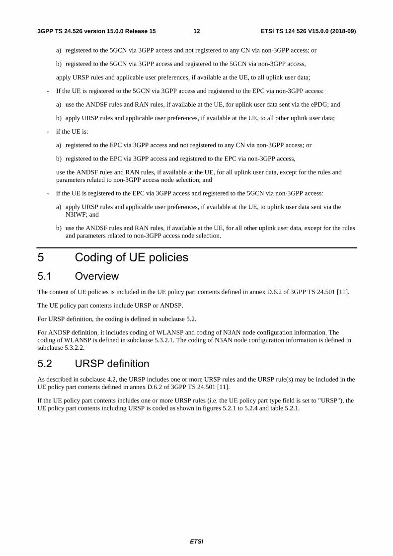
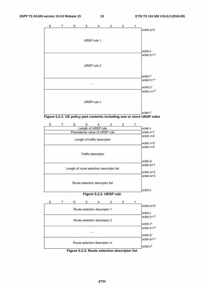
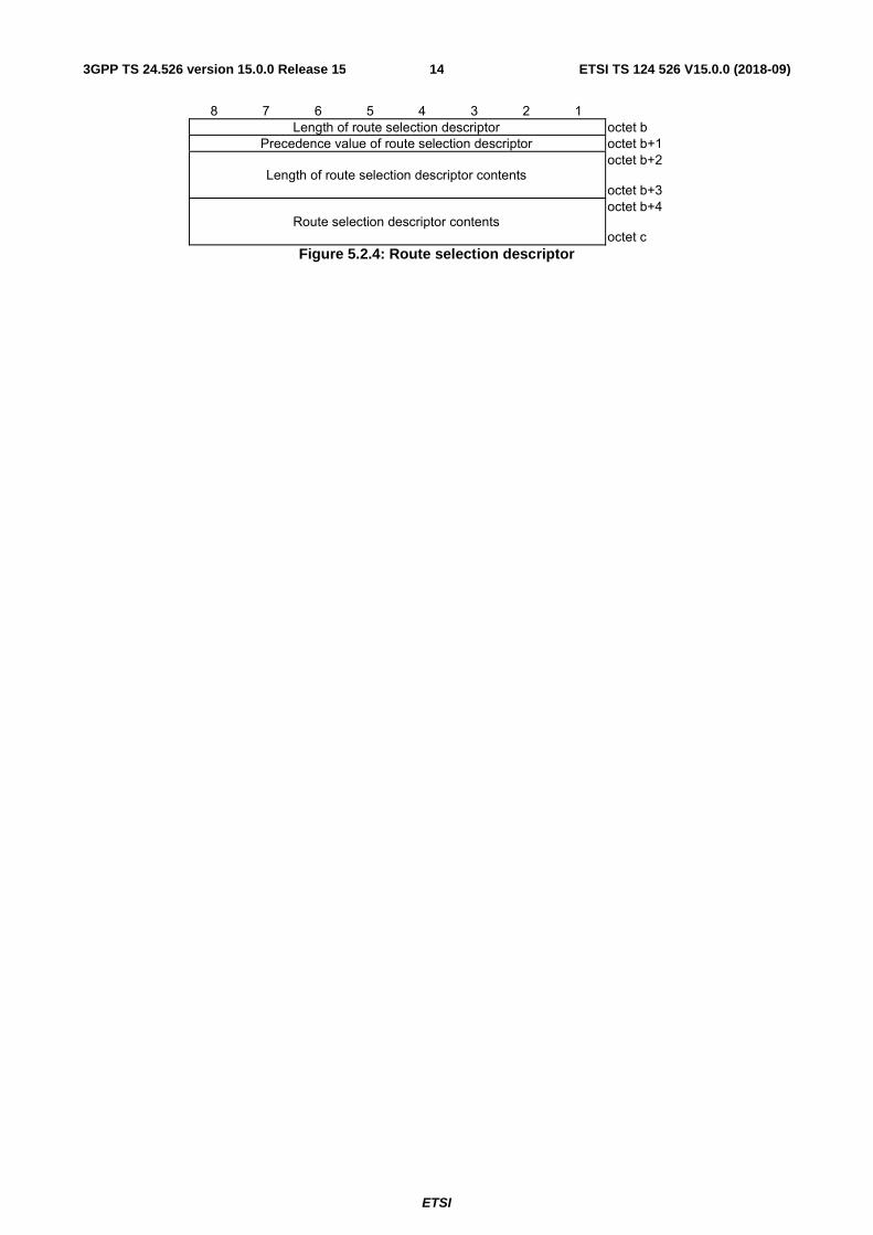
If the UE policy part contents includes one or more URSP rules (i.e. the UE policy part type field is set to "URSP"), the UE policy part contents including URSP is coded as shown in figures 5.2.1 to 5.2.4 and table 5.2.1.
ETSI
ETSI TS 124 526 V15.0.0 (2018-09)133GPP TS 24.526 version 15.0.0 Release 15
8 7 6 5 4 3 2 1
URSP rule 1
octet q+3 octet s
URSP rule 2
octet s+1* octet t*
…
octet t+1* octet u*
URSP rule n
octet u+1* octet r*
Figure 5.2.1: UE policy part contents including one or more URSP rules
8 7 6 5 4 3 2 1 Length of URSP rule octet v
Precedence value of URSP rule octet v+1
Length of traffic descriptor
octet v+2 octet v+3
Traffic descriptor
octet v+4 octet w
Length of route selection descriptor list
octet w+1 octet w+2
Route selection descriptor list
octet w+3 octet x
Figure 5.2.2: URSP rule
8 7 6 5 4 3 2 1
Route selection descriptor 1 octet w+3 octet y
Route selection descriptor 2
octet y+1* octet z*
…
octet z+1* octet a*
Route selection descriptor m
octet a+1* octet x*
Figure 5.2.3: Route selection descriptor list
ETSI
ETSI TS 124 526 V15.0.0 (2018-09)143GPP TS 24.526 version 15.0.0 Release 15
8 7 6 5 4 3 2 1 Length of route selection descriptor octet b
Precedence value of route selection descriptor octet b+1
Length of route selection descriptor contents
octet b+2 octet b+3
Route selection descriptor contents
octet b+4 octet c
Figure 5.2.4: Route selection descriptor
ETSI
ETSI TS 124 526 V15.0.0 (2018-09)153GPP TS 24.526 version 15.0.0 Release 15
Table 5.2.1: UE policy part contents including a URSP rule
ETSI
ETSI TS 124 526 V15.0.0 (2018-09)163GPP TS 24.526 version 15.0.0 Release 15
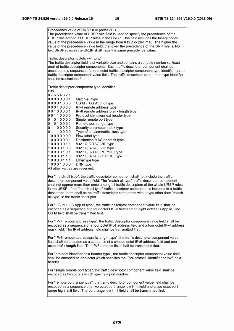
Precedence value of URSP rule (octet v+1) The precedence value of URSP rule field is used to specify the precedence of the URSP rule among all URSP rules in the URSP. This field includes the binary coded value of the precedence value in the range from 0 to 255 (decimal). The higher the value of the precedence value field, the lower the precedence of the URP rule is. No two URSP rules in the URSP shall have the same precedence value. Traffic descriptor (octets v+4 to w) The traffic descriptor field is of variable size and contains a variable number (at least one) of traffic descriptor components. Each traffic descriptor component shall be encoded as a sequence of a one octet traffic descriptor component type identifier and a traffic descriptor component value field. The traffic descriptor component type identifier shall be transmitted first. Traffic descriptor component type identifier Bits 8 7 6 5 4 3 2 1 0 0 0 0 0 0 0 1 Match-all type 0 0 0 0 1 0 0 0 OS Id + OS App Id type 0 0 0 1 0 0 0 0 IPv4 remote address type 0 0 1 0 0 0 0 1 IPv6 remote address/prefix length type 0 0 1 1 0 0 0 0 Protocol identifier/next header type 0 1 0 1 0 0 0 0 Single remote port type 0 1 0 1 0 0 0 1 Remote port range type 0 1 1 0 0 0 0 0 Security parameter index type 0 1 1 1 0 0 0 0 Type of service/traffic class type 1 0 0 0 0 0 0 0 Flow label type 1 0 0 0 0 0 0 1 Destination MAC address type 1 0 0 0 0 0 1 1 802.1Q C-TAG VID type 1 0 0 0 0 1 0 0 802.1Q S-TAG VID type 1 0 0 0 0 1 0 1 802.1Q C-TAG PCP/DEI type 1 0 0 0 0 1 1 0 802.1Q S-TAG PCP/DEI type 1 0 0 0 0 1 1 1 Ethertype type 1 0 0 0 1 0 0 0 DNN type All other values are reserved. For "match-all type", the traffic descriptor component shall not include the traffic descriptor component value field. The "match-all type" traffic descriptor component shall not appear more than once among all traffic descriptors of the whole URSP rules in the URSP. If the "match-all type" traffic descriptor component is included in a traffic descriptor, there shall be no traffic descriptor component with a type other than "match-all type" in the traffic descriptor. For "OS Id + OS App Id type", the traffic descriptor component value field shall be encoded as a sequence of a four octet OS Id field and an eight octet OS App Id. The OS Id field shall be transmitted first. For "IPv4 remote address type", the traffic descriptor component value field shall be encoded as a sequence of a four octet IPv4 address field and a four octet IPv4 address mask field. The IPv4 address field shall be transmitted first. For "IPv6 remote address/prefix length type", the traffic descriptor component value field shall be encoded as a sequence of a sixteen octet IPv6 address field and one octet prefix length field. The IPv6 address field shall be transmitted first. For "protocol identifier/next header type", the traffic descriptor component value field shall be encoded as one octet which specifies the IPv4 protocol identifier or Ipv6 next header. For "single remote port type", the traffic descriptor component value field shall be encoded as two octets which specify a port number. For "remote port range type", the traffic descriptor component value field shall be encoded as a sequence of a two octet port range low limit field and a two octet port range high limit field. The port range low limit field shall be transmitted first.
ETSI
ETSI TS 124 526 V15.0.0 (2018-09)173GPP TS 24.526 version 15.0.0 Release 15
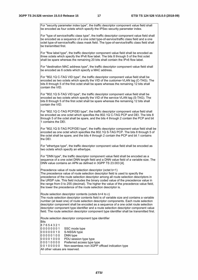
For "security parameter index type", the traffic descriptor component value field shall be encoded as four octets which specify the IPSec security parameter index. For "type of service/traffic class type", the traffic descriptor component value field shall be encoded as a sequence of a one octet type-of-service/traffic class field and a one octet type-of-service/traffic class mask field. The type-of-service/traffic class field shall be transmitted first. For "flow label type", the traffic descriptor component value field shall be encoded as three octets which specify the IPv6 flow label. The bits 8 through 5 of the first octet shall be spare whereas the remaining 20 bits shall contain the IPv6 flow label. For "destination MAC address type", the traffic descriptor component value field shall be encoded as 6 octets which specify a MAC address. For "802.1Q C-TAG VID type", the traffic descriptor component value field shall be encoded as two octets which specify the VID of the customer-VLAN tag (C-TAG). The bits 8 through 5 of the first octet shall be spare whereas the remaining 12 bits shall contain the VID. For "802.1Q S-TAG VID type", the traffic descriptor component value field shall be encoded as two octets which specify the VID of the service-VLAN tag (S-TAG). The bits 8 through 5 of the first octet shall be spare whereas the remaining 12 bits shall contain the VID. For "802.1Q C-TAG PCP/DEI type", the traffic descriptor component value field shall be encoded as one octet which specifies the 802.1Q C-TAG PCP and DEI. The bits 8 through 5 of the octet shall be spare, and the bits 4 through 2 contain the PCP and bit 1 contains the DEI. For "802.1Q S-TAG PCP/DEI type", the traffic descriptor component value field shall be encoded as one octet which specifies the 802.1Q S-TAG PCP. The bits 8 through 5 of the octet shall be spare, and the bits 4 through 2 contain the PCP and bit 1 contains the DEI. For "ethertype type", the traffic descriptor component value field shall be encoded as two octets which specify an ethertype. For "DNN type", the traffic descriptor component value field shall be encoded as a sequence of a one octet DNN length field and a DNN value field of a variable size. The DNN value contains an APN as defined in 3GPP TS 23.003 [4]. Precedence value of route selection descriptor (octet b+1) The precedence value of route selection descriptor field is used to specify the precedence of the route selection descriptor among all route selection descriptors in the URSP rule. This field includes the binary coded value of the precedence value in the range from 0 to 255 (decimal). The higher the value of the precedence value field, the lower the precedence of the route selection descriptor is. Route selection descriptor contents (octets b+4 to c) The route selection descriptor contents field is of variable size and contains a variable number (at least one) of route selection descriptor components. Each route selection descriptor component shall be encoded as a sequence of a one octet route selection descriptor component type identifier and a route selection descriptor component value field. The route selection descriptor component type identifier shall be transmitted first. Route selection descriptor component type identifier Bits 8 7 6 5 4 3 2 1 0 0 0 0 0 0 0 1 SSC mode type 0 0 0 0 0 0 1 0 S-NSSAI type 0 0 0 0 0 1 0 0 DNN type 0 0 0 0 1 0 0 0 PDU session type type 0 0 0 1 0 0 0 0 Preferred access type type 0 0 1 0 0 0 0 0 Non-seamless non-3GPP offload indication type All other values are reserved.
ETSI
ETSI TS 124 526 V15.0.0 (2018-09)183GPP TS 24.526 version 15.0.0 Release 15
For "SSC mode type", the route selection descriptor component value field shall be encoded as a one octet SSC mode field. The bits 8 through 5 of the octet shall be spare, and the bits 4 through 1 shall be encoded as the value part of the SSC mode information element defined in subclause 9.8.4.12 of 3GPP TS 24.501 [11]. The "SSC mode type" route selection descriptor component shall not appear more than once in the route selection descriptor. For "S-NSSAI type", the route selection descriptor component value field shall be encoded as a sequence of a one octet S-NSSAI length field and an S-NSSAI value field of a variable size. The S-NSSAI value shall be encoded as the value part of S-NSSAI information element defined in subclause 9.8.3.47 of 3GPP TS 24.501 [11]. For "DNN type", the route selection descriptor component value field shall be encoded as a sequence of a one octet DNN length field and a DNN value field of a variable size. The DNN value contains an APN as defined in 3GPP TS 23.003 [4]. For "PDU session type", the route selection descriptor component value field shall be encoded as a one octet PDU session type field. The bits 8 through 5 of the octet shall be spare, and the bits 4 through 1 shall be encoded as the value part of the PDU session type information element defined in subclause 9.8.4.8 of 3GPP TS 24.501 [11]. The "PDU session type" route selection descriptor component shall not appear more than once in the route selection descriptor. For "preferred access type", the route selection descriptor component value field shall be encoded as a one octet preferred access type field. The bits 8 through 3 shall be spare, and the bits 2 and 1 shall be encoded as the value par to the access type information element defined in subclause 9.8.3.8 of 3GPP TS 24.501 [11]. The "preferred access type" route selection descriptor component shall not appear more than once in the route selection descriptor. For "non-seamless non-3GPP offload indication type", the route selection descriptor component shall not include the route selection descriptor component value field. The "non-seamless non-3GPP offload indication type" route selection descriptor component shall not appear more than once in the route selection descriptor. If the "non-seamless non-3GPP offload indication type" route selection descriptor component is included in a route selection descriptor, there shall be no route selection descriptor component with a type other than "non-seamless non-3GPP offload indication type" in the route selection descriptor.
5.3 ANDSP definition 5.3.1 General
5.3.2 ANDSP definition The purpose of the ANDSP is to indicate the WLAN Selection Policy (WLANSP) and non-3GPP access network (N3AN) node configuration information related to access network discovery and selection and N3AN node selection for non-3GPP access network.
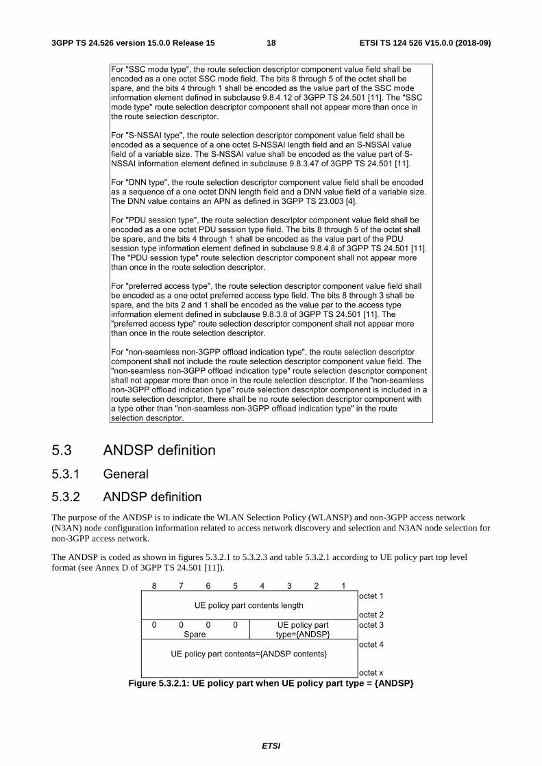
The ANDSP is coded as shown in figures 5.3.2.1 to 5.3.2.3 and table 5.3.2.1 according to UE policy part top level format (see Annex D of 3GPP TS 24.501 [11]).
8 7 6 5 4 3 2 1
UE policy part contents length
octet 1 octet 2
0 0 0 0 UE policy part type={ANDSP}
octet 3 Spare
UE policy part contents={ANDSP contents}
octet 4 octet x
Figure 5.3.2.1: UE policy part when UE policy part type = {ANDSP}
ETSI
ETSI TS 124 526 V15.0.0 (2018-09)193GPP TS 24.526 version 15.0.0 Release 15
8 7 6 5 4 3 2 1
ANDSP info #1
octet 4 octet a
ANDSP info #2
octet a+1 octet b
…
octet b+1 octet w
ANDSP info #n
octet w+1 octet x
Figure 5.3.2.2: ANDSP contents
8 7 6 5 4 3 2 1 0 0 0 0 ANDSP Info type octet k
Spare
Length of ANDSP info
octet k+1 octet k+2
ANDSP info contents
octet k+3 octet l
Figure 5.3.2.3: ANDSP Info
Table 5.3.2.1: ANDSP information format
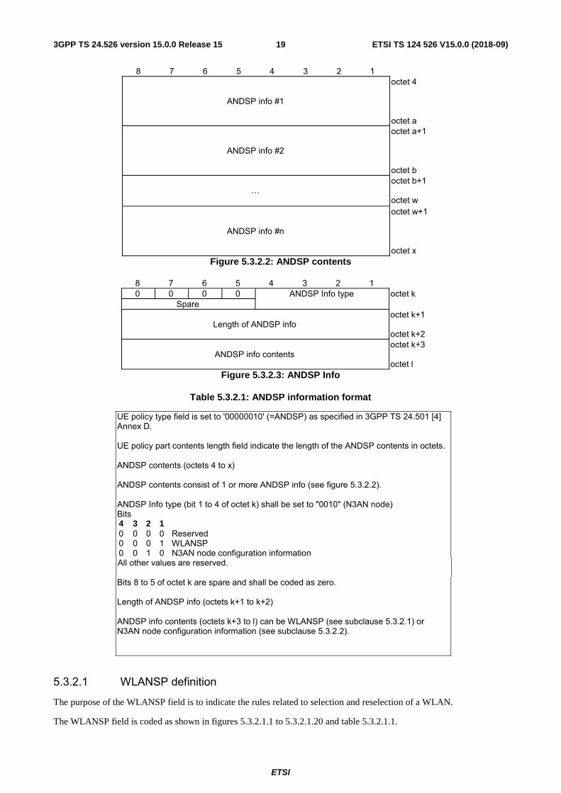
UE policy type field is set to '00000010' (=ANDSP) as specified in 3GPP TS 24.501 [4] Annex D. UE policy part contents length field indicate the length of the ANDSP contents in octets. ANDSP contents (octets 4 to x) ANDSP contents consist of 1 or more ANDSP info (see figure 5.3.2.2). ANDSP Info type (bit 1 to 4 of octet k) shall be set to "0010" (N3AN node) Bits 4 3 2 1 0 0 0 0 Reserved 0 0 0 1 WLANSP 0 0 1 0 N3AN node configuration information All other values are reserved. Bits 8 to 5 of octet k are spare and shall be coded as zero. Length of ANDSP info (octets k+1 to k+2) ANDSP info contents (octets k+3 to l) can be WLANSP (see subclause 5.3.2.1) or N3AN node configuration information (see subclause 5.3.2.2).
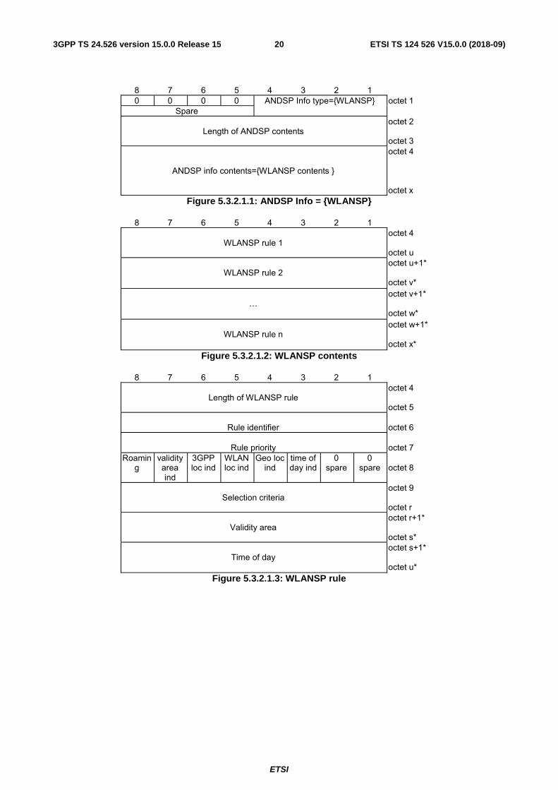
5.3.2.1 WLANSP definition
The purpose of the WLANSP field is to indicate the rules related to selection and reselection of a WLAN.
The WLANSP field is coded as shown in figures 5.3.2.1.1 to 5.3.2.1.20 and table 5.3.2.1.1.
ETSI
ETSI TS 124 526 V15.0.0 (2018-09)203GPP TS 24.526 version 15.0.0 Release 15
8 7 6 5 4 3 2 1 0 0 0 0 ANDSP Info type={WLANSP} octet 1
Spare
Length of ANDSP contents
octet 2 octet 3
ANDSP info contents={WLANSP contents }
octet 4 octet x
Figure 5.3.2.1.1: ANDSP Info = {WLANSP}
8 7 6 5 4 3 2 1
WLANSP rule 1 octet 4 octet u
WLANSP rule 2
octet u+1* octet v*
…
octet v+1* octet w*
WLANSP rule n
octet w+1* octet x*
Figure 5.3.2.1.2: WLANSP contents
8 7 6 5 4 3 2 1
Length of WLANSP rule
octet 4 octet 5
Rule identifier
octet 6
Rule priority
octet 7
Roaming
validity area ind
3GPP loc ind
WLAN loc ind
Geo loc ind
time of day ind
0 spare
0 spare
octet 8
Selection criteria
octet 9 octet r
Validity area
octet r+1* octet s*
Time of day
octet s+1* octet u*
Figure 5.3.2.1.3: WLANSP rule
ETSI
ETSI TS 124 526 V15.0.0 (2018-09)213GPP TS 24.526 version 15.0.0 Release 15
8 7 6 5 4 3 2 1
length of selection criteria octet 9 octet 10
number of selection criteria entries
octet 11
Selection criteria entry 1
octet 12 octet a
Selection criteria entry 2
octet a+1* octet b*
…
octet b+1* octet c*
Selection criteria entry n
octet c+1* octet r*
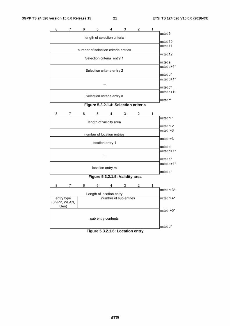
Figure 5.3.2.1.4: Selection criteria
8 7 6 5 4 3 2 1
length of validity area octet r+1 octet r+2
number of location entries
octet r+3
location entry 1
octet r+3 octet d
….
octet d+1* octet e*
location entry m
octet e+1* octet s*
Figure 5.3.2.1.5: Validity area
8 7 6 5 4 3 2 1
Length of location entry octet r+3*
entry type {3GPP, WLAN,
Geo}
number of sub entries octet r+4*
sub entry contents
octet r+5* octet d*
Figure 5.3.2.1.6: Location entry
ETSI
ETSI TS 124 526 V15.0.0 (2018-09)223GPP TS 24.526 version 15.0.0 Release 15
8 7 6 5 4 3 2 1
Length of location entry octet r+3*
entry type= {3GPP location}
number of sub entries octet r+4*
3GPP location sub entry 1
octet r+5 octet f
3GPP location sub entry 2
octet f+1* octet g*
…
octet g+1* octet h*
3GPP location sub entry o
octet h+1* octet d*
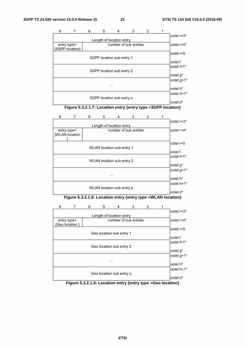
Figure 5.3.2.1.7: Location entry {entry type =3GPP location}
8 7 6 5 4 3 2 1
Length of location entry octet r+3*
entry type= {WLAN location
}
number of sub entries octet r+4*
WLAN location sub entry 1
octet r+5 octet f
WLAN location sub entry 2
octet f+1* octet g*
…
octet g+1* octet h*
WLAN location sub entry p
octet h+1* octet d*
Figure 5.3.2.1.8: Location entry {entry type =WLAN location}
8 7 6 5 4 3 2 1
Length of location entry octet r+3*
entry type= {Geo location }
number of sub entries octet r+4*
Geo location sub entry 1
octet r+5 octet f
Geo location sub entry 2
octet f+1* octet g*
…
octet g+1* octet h*
Geo location sub entry q
octet h+1* octet d*
Figure 5.3.2.1.9: Location entry {entry type =Geo location}
ETSI
ETSI TS 124 526 V15.0.0 (2018-09)233GPP TS 24.526 version 15.0.0 Release 15
8 7 6 5 4 3 2 1
Length of 3GPP location sub entry octet r+5 octet r+6
MCC digit 2
MCC digit 1
octet r+7
MNC digit 3
MCC digit 3
octet r+8
MNC digit 2
MNC digit 1
octet r+9
number of location fields
octet r+10*
location field 1
octet r+11* octet l*
…
octet l+1* octet m*
location field n
octet m+1* octet f*
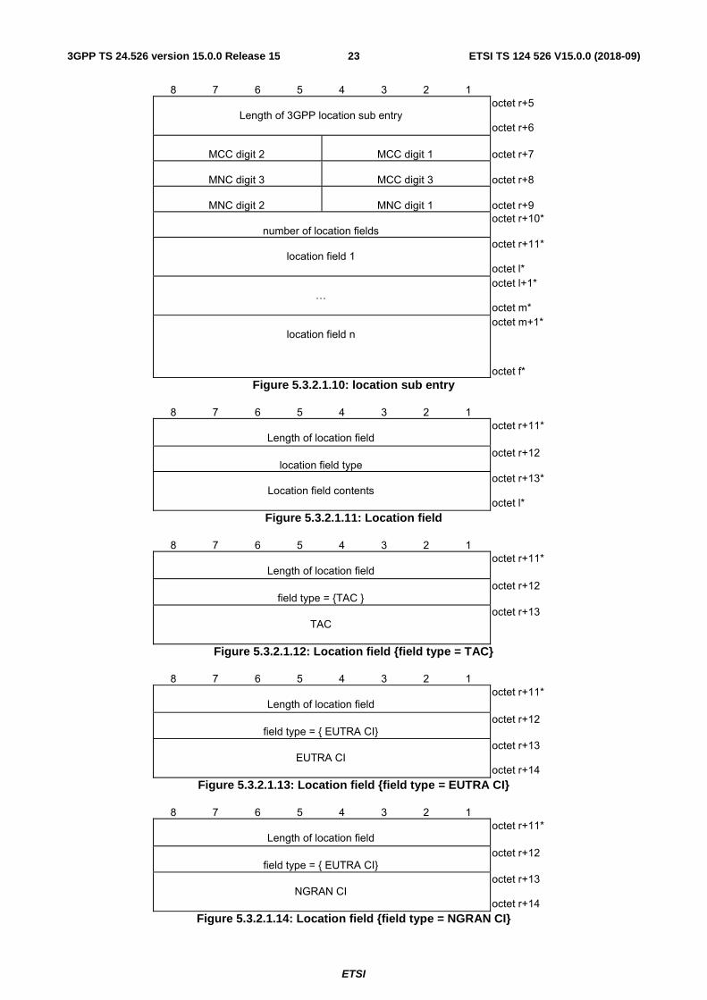
Figure 5.3.2.1.10: location sub entry
8 7 6 5 4 3 2 1
Length of location field octet r+11*
location field type
octet r+12
Location field contents
octet r+13* octet l*
Figure 5.3.2.1.11: Location field
8 7 6 5 4 3 2 1
Length of location field octet r+11*
field type = {TAC }
octet r+12
TAC
octet r+13
Figure 5.3.2.1.12: Location field {field type = TAC}
8 7 6 5 4 3 2 1
Length of location field octet r+11*
field type = { EUTRA CI}
octet r+12
EUTRA CI
octet r+13 octet r+14
Figure 5.3.2.1.13: Location field {field type = EUTRA CI}
8 7 6 5 4 3 2 1
Length of location field octet r+11*
field type = { EUTRA CI}
octet r+12
NGRAN CI
octet r+13 octet r+14
Figure 5.3.2.1.14: Location field {field type = NGRAN CI}
ETSI
ETSI TS 124 526 V15.0.0 (2018-09)243GPP TS 24.526 version 15.0.0 Release 15
8 7 6 5 4 3 2 1
Length of time of day octet s+1 octet s+2
number of time of day entries
octet s+3
Time of day entry 1
octet s+4 octet n1
Time of day entry 2
octet n1+1* octet n2*
…
octet n2+1* octet n3*
Time of day entry n
octet n3+1* octet u*
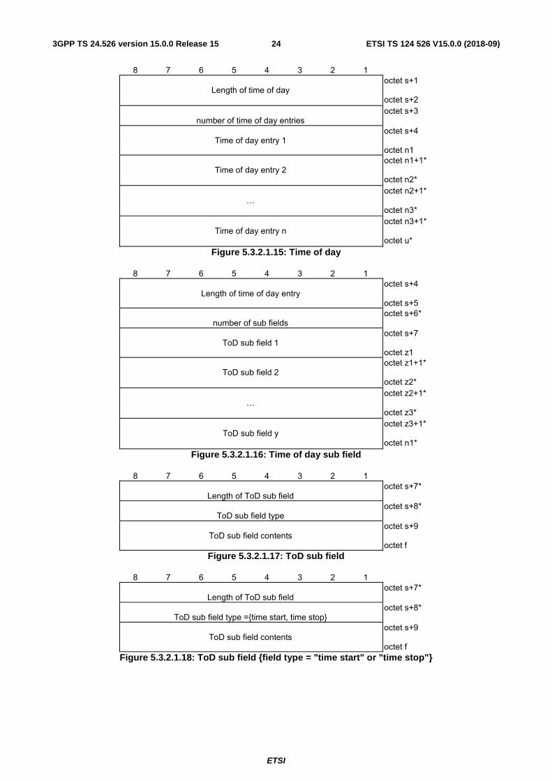
Figure 5.3.2.1.15: Time of day
8 7 6 5 4 3 2 1
Length of time of day entry octet s+4 octet s+5
number of sub fields
octet s+6*
ToD sub field 1
octet s+7 octet z1
ToD sub field 2
octet z1+1* octet z2*
…
octet z2+1* octet z3*
ToD sub field y
octet z3+1* octet n1*
Figure 5.3.2.1.16: Time of day sub field
8 7 6 5 4 3 2 1
Length of ToD sub field octet s+7*
ToD sub field type
octet s+8*
ToD sub field contents
octet s+9 octet f
Figure 5.3.2.1.17: ToD sub field
8 7 6 5 4 3 2 1
Length of ToD sub field octet s+7*
ToD sub field type ={time start, time stop}
octet s+8*
ToD sub field contents
octet s+9 octet f
Figure 5.3.2.1.18: ToD sub field {field type = "time start" or "time stop"}
ETSI
ETSI TS 124 526 V15.0.0 (2018-09)253GPP TS 24.526 version 15.0.0 Release 15
8 7 6 5 4 3 2 1
Length of ToD sub field octet s+7*
ToD sub field type ={ date start, date stop }
octet s+8*
ToD sub field contents
octet s+9 octet f
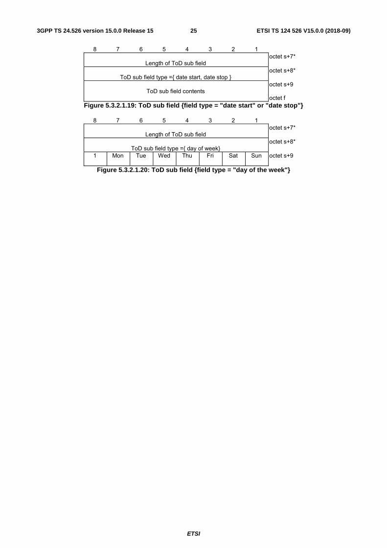
Figure 5.3.2.1.19: ToD sub field {field type = "date start" or "date stop"}
8 7 6 5 4 3 2 1
Length of ToD sub field octet s+7*
ToD sub field type ={ day of week}
octet s+8*
1 Mon Tue Wed Thu Fri Sat Sun octet s+9
Figure 5.3.2.1.20: ToD sub field {field type = "day of the week"}
ETSI
ETSI TS 124 526 V15.0.0 (2018-09)263GPP TS 24.526 version 15.0.0 Release 15
Table 5.3.1.1: WLANSP information element
ETSI
ETSI TS 124 526 V15.0.0 (2018-09)273GPP TS 24.526 version 15.0.0 Release 15
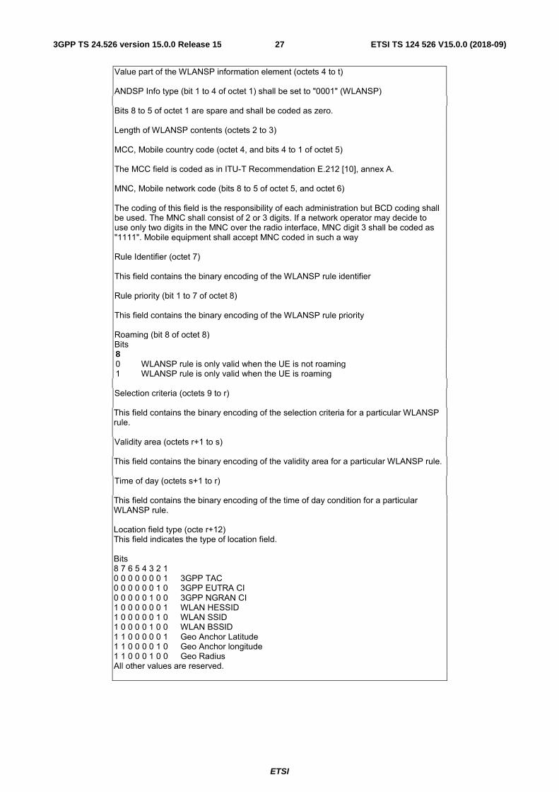
Value part of the WLANSP information element (octets 4 to t) ANDSP Info type (bit 1 to 4 of octet 1) shall be set to "0001" (WLANSP) Bits 8 to 5 of octet 1 are spare and shall be coded as zero. Length of WLANSP contents (octets 2 to 3) MCC, Mobile country code (octet 4, and bits 4 to 1 of octet 5) The MCC field is coded as in ITU-T Recommendation E.212 [10], annex A. MNC, Mobile network code (bits 8 to 5 of octet 5, and octet 6) The coding of this field is the responsibility of each administration but BCD coding shall be used. The MNC shall consist of 2 or 3 digits. If a network operator may decide to use only two digits in the MNC over the radio interface, MNC digit 3 shall be coded as "1111". Mobile equipment shall accept MNC coded in such a way Rule Identifier (octet 7) This field contains the binary encoding of the WLANSP rule identifier Rule priority (bit 1 to 7 of octet 8) This field contains the binary encoding of the WLANSP rule priority Roaming (bit 8 of octet 8) Bits 8 0 WLANSP rule is only valid when the UE is not roaming 1 WLANSP rule is only valid when the UE is roaming Selection criteria (octets 9 to r) This field contains the binary encoding of the selection criteria for a particular WLANSP rule. Validity area (octets r+1 to s) This field contains the binary encoding of the validity area for a particular WLANSP rule. Time of day (octets s+1 to r) This field contains the binary encoding of the time of day condition for a particular WLANSP rule. Location field type (octe r+12) This field indicates the type of location field. Bits 8 7 6 5 4 3 2 1 0 0 0 0 0 0 0 1 3GPP TAC 0 0 0 0 0 0 1 0 3GPP EUTRA CI 0 0 0 0 0 1 0 0 3GPP NGRAN CI 1 0 0 0 0 0 0 1 WLAN HESSID 1 0 0 0 0 0 1 0 WLAN SSID 1 0 0 0 0 1 0 0 WLAN BSSID 1 1 0 0 0 0 0 1 Geo Anchor Latitude 1 1 0 0 0 0 1 0 Geo Anchor longitude 1 1 0 0 0 1 0 0 Geo Radius All other values are reserved.
ETSI
ETSI TS 124 526 V15.0.0 (2018-09)283GPP TS 24.526 version 15.0.0 Release 15
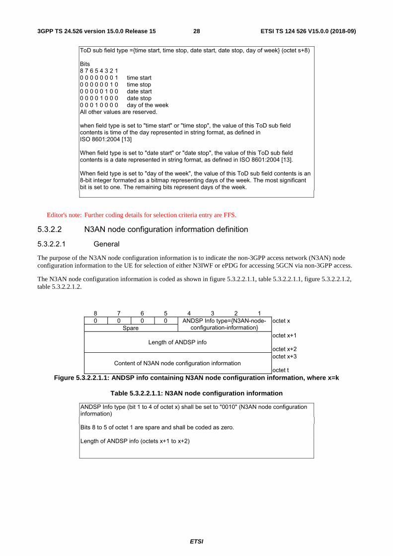
ToD sub field type ={time start, time stop, date start, date stop, day of week} (octet s+8) Bits 8 7 6 5 4 3 2 1 0 0 0 0 0 0 0 1 time start 0 0 0 0 0 0 1 0 time stop 0 0 0 0 0 1 0 0 date start 0 0 0 0 1 0 0 0 date stop 0 0 0 1 0 0 0 0 day of the week All other values are reserved. when field type is set to "time start" or "time stop", the value of this ToD sub field contents is time of the day represented in string format, as defined in ISO 8601:2004 [13] When field type is set to "date start" or "date stop", the value of this ToD sub field contents is a date represented in string format, as defined in ISO 8601:2004 [13]. When field type is set to "day of the week", the value of this ToD sub field contents is an 8-bit integer formated as a bitmap representing days of the week. The most significant bit is set to one. The remaining bits represent days of the week.
Editor's note: Further coding details for selection criteria entry are FFS.
5.3.2.2 N3AN node configuration information definition
5.3.2.2.1 General
The purpose of the N3AN node configuration information is to indicate the non-3GPP access network (N3AN) node configuration information to the UE for selection of either N3IWF or ePDG for accessing 5GCN via non-3GPP access.
The N3AN node configuration information is coded as shown in figure 5.3.2.2.1.1, table 5.3.2.2.1.1, figure 5.3.2.2.1.2, table 5.3.2.2.1.2.
8 7 6 5 4 3 2 1 0 0 0 0 ANDSP Info type={N3AN-node-
configuration-information} octet x
Spare
Length of ANDSP info
octet x+1 octet x+2
Content of N3AN node configuration information
octet x+3 octet t
Figure 5.3.2.2.1.1: ANDSP info containing N3AN node configuration information, where x=k
Table 5.3.2.2.1.1: N3AN node configuration information
ANDSP Info type (bit 1 to 4 of octet x) shall be set to "0010" (N3AN node configuration information) Bits 8 to 5 of octet 1 are spare and shall be coded as zero. Length of ANDSP info (octets x+1 to x+2)
ETSI
ETSI TS 124 526 V15.0.0 (2018-09)293GPP TS 24.526 version 15.0.0 Release 15
8 7 6 5 4 3 2 1
Length of N3AN node selection information octet x+3 octet x+4
Content of N3AN node selection information
octet x+5 octet v
N3AN node configuration information type (type = home N3IWF identifier configuration)
octet v+1
Length of home N3IWF identifier configuration
octet v+2 octet v+3
Content of home N3IWF identifier configuration
octet v+4 octet w
N3AN node configuration information type (type = home ePDG identifier configuration)
octet w+1
Length of home ePDG identifier configuration
octet w+2 octet w+3
Content of home ePDG identifier configuration
octet w+4 octet z
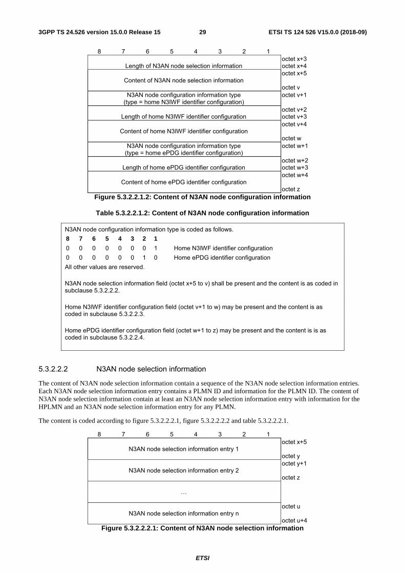
Figure 5.3.2.2.1.2: Content of N3AN node configuration information
Table 5.3.2.2.1.2: Content of N3AN node configuration information
N3AN node configuration information type is coded as follows. 8 7 6 5 4 3 2 1 0 0 0 0 0 0 0 1 Home N3IWF identifier configuration 0 0 0 0 0 0 1 0 Home ePDG identifier configuration All other values are reserved. N3AN node selection information field (octet x+5 to v) shall be present and the content is as coded in subclause 5.3.2.2.2. Home N3IWF identifier configuration field (octet v+1 to w) may be present and the content is as coded in subclause 5.3.2.2.3. Home ePDG identifier configuration field (octet w+1 to z) may be present and the content is is as coded in subclause 5.3.2.2.4.
5.3.2.2.2 N3AN node selection information
The content of N3AN node selection information contain a sequence of the N3AN node selection information entries. Each N3AN node selection information entry contains a PLMN ID and information for the PLMN ID. The content of N3AN node selection information contain at least an N3AN node selection information entry with information for the HPLMN and an N3AN node selection information entry for any PLMN.
The content is coded according to figure 5.3.2.2.2.1, figure 5.3.2.2.2.2 and table 5.3.2.2.2.1.
8 7 6 5 4 3 2 1
N3AN node selection information entry 1 octet x+5 octet y
N3AN node selection information entry 2
octet y+1 octet z
…
N3AN node selection information entry n
octet u octet u+4
Figure 5.3.2.2.2.1: Content of N3AN node selection information
ETSI
ETSI TS 124 526 V15.0.0 (2018-09)303GPP TS 24.526 version 15.0.0 Release 15
8 7 6 5 4 3 2 1 Length of N3AN node selection information entry octet x+5 MCC digit 2 MCC digit 1 octet x+6 MNC digit 3 MCC digit 3 octet x+7 MNC digit 2 MNC digit 1 octet x+8
FQDN format Preference
Priority octet x+9
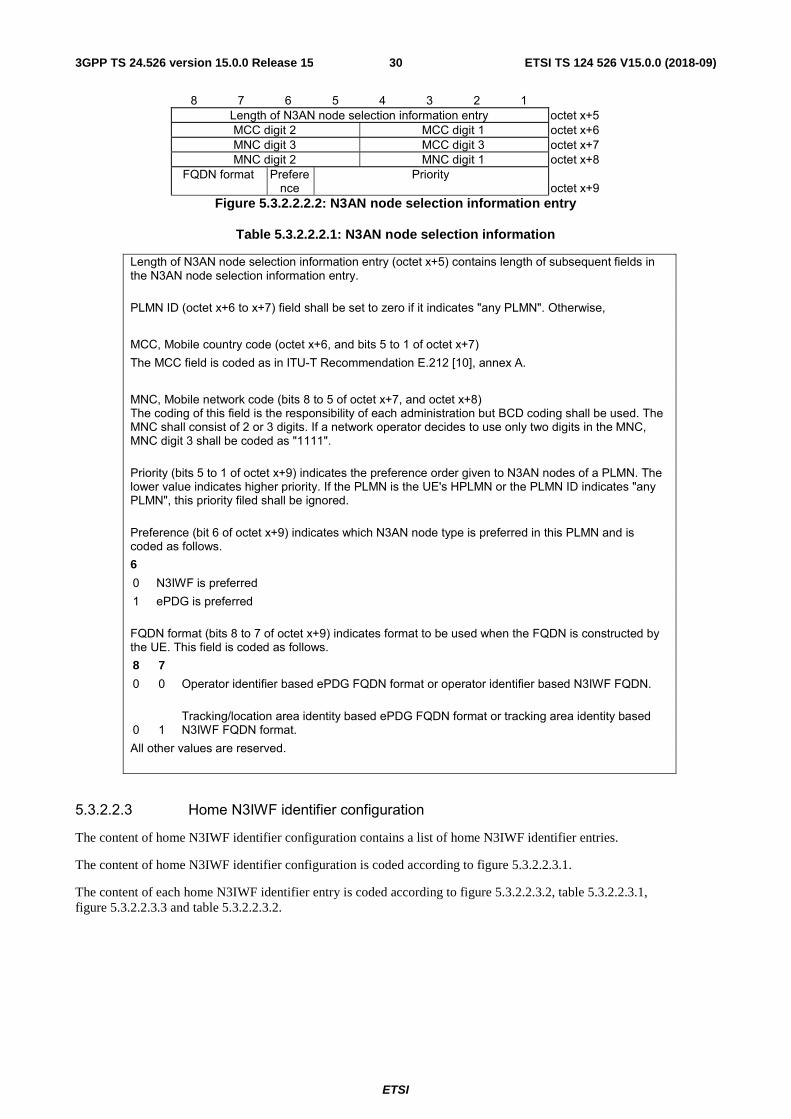
Figure 5.3.2.2.2.2: N3AN node selection information entry
Table 5.3.2.2.2.1: N3AN node selection information
Length of N3AN node selection information entry (octet x+5) contains length of subsequent fields in the N3AN node selection information entry. PLMN ID (octet x+6 to x+7) field shall be set to zero if it indicates "any PLMN". Otherwise, MCC, Mobile country code (octet x+6, and bits 5 to 1 of octet x+7) The MCC field is coded as in ITU-T Recommendation E.212 [10], annex A. MNC, Mobile network code (bits 8 to 5 of octet x+7, and octet x+8) The coding of this field is the responsibility of each administration but BCD coding shall be used. The MNC shall consist of 2 or 3 digits. If a network operator decides to use only two digits in the MNC, MNC digit 3 shall be coded as "1111". Priority (bits 5 to 1 of octet x+9) indicates the preference order given to N3AN nodes of a PLMN. The lower value indicates higher priority. If the PLMN is the UE's HPLMN or the PLMN ID indicates "any PLMN", this priority filed shall be ignored. Preference (bit 6 of octet x+9) indicates which N3AN node type is preferred in this PLMN and is coded as follows. 6 0 N3IWF is preferred 1 ePDG is preferred FQDN format (bits 8 to 7 of octet x+9) indicates format to be used when the FQDN is constructed by the UE. This field is coded as follows. 8 7 0 0 Operator identifier based ePDG FQDN format or operator identifier based N3IWF FQDN.
0 1 Tracking/location area identity based ePDG FQDN format or tracking area identity based N3IWF FQDN format.
All other values are reserved.
5.3.2.2.3 Home N3IWF identifier configuration
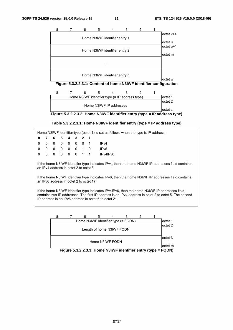
The content of home N3IWF identifier configuration contains a list of home N3IWF identifier entries.
The content of home N3IWF identifier configuration is coded according to figure 5.3.2.2.3.1.
The content of each home N3IWF identifier entry is coded according to figure 5.3.2.2.3.2, table 5.3.2.2.3.1, figure 5.3.2.2.3.3 and table 5.3.2.2.3.2.
ETSI
ETSI TS 124 526 V15.0.0 (2018-09)313GPP TS 24.526 version 15.0.0 Release 15
8 7 6 5 4 3 2 1
Home N3IWF identifier entry 1 octet v+4 octet u
Home N3IWF identifier entry 2
octet u+1 octet m
…
Home N3IWF identifier entry n
octet w
Figure 5.3.2.2.3.1: Content of home N3IWF identifier configuration
8 7 6 5 4 3 2 1 Home N3IWF identifier type (= IP address type) octet 1
Home N3IWF IP addresses
octet 2 octet z
Figure 5.3.2.2.3.2: Home N3IWF identifier entry (type = IP address type)
Table 5.3.2.2.3.1: Home N3IWF identifier entry (type = IP address type)
Home N3IWF identifier type (octet 1) is set as follows when the type is IP address. 8 7 6 5 4 3 2 1 0 0 0 0 0 0 0 1 IPv4 0 0 0 0 0 0 1 0 IPv6 0 0 0 0 0 0 1 1 IPv4IPv6 If the home N3IWF identifier type indicates IPv4, then the home N3IWF IP addresses field contains an IPv4 address in octet 2 to octet 5. If the home N3IWF identifier type indicates IPv6, then the home N3IWF IP addresses field contains an IPv6 address in octet 2 to octet 17. If the home N3IWF identifier type indicates IPv4IPv6, then the home N3IWF IP addresses field contains two IP addresses. The first IP address is an IPv4 address in octet 2 to octet 5. The second IP address is an IPv6 address in octet 6 to octet 21.
8 7 6 5 4 3 2 1 Home N3IWF identifier type (= FQDN) octet 1
Length of home N3IWF FQDN
octet 2
Home N3IWF FQDN
octet 3 octet m
Figure 5.3.2.2.3.3: Home N3IWF identifier entry (type = FQDN)
ETSI
ETSI TS 124 526 V15.0.0 (2018-09)323GPP TS 24.526 version 15.0.0 Release 15
Table 5.3.2.2.3.2: Home N3IWF identifier entry (type = FQDN)
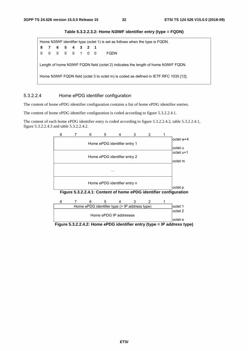
Home N3IWF identifier type (octet 1) is set as follows when the type is FQDN. 8 7 6 5 4 3 2 1 0 0 0 0 0 1 0 0 FQDN Length of home N3IWF FQDN field (octet 2) indicates the length of home N3IWF FQDN. Home N3IWF FQDN field (octet 3 to octet m) is coded as defined in IETF RFC 1035 [12].
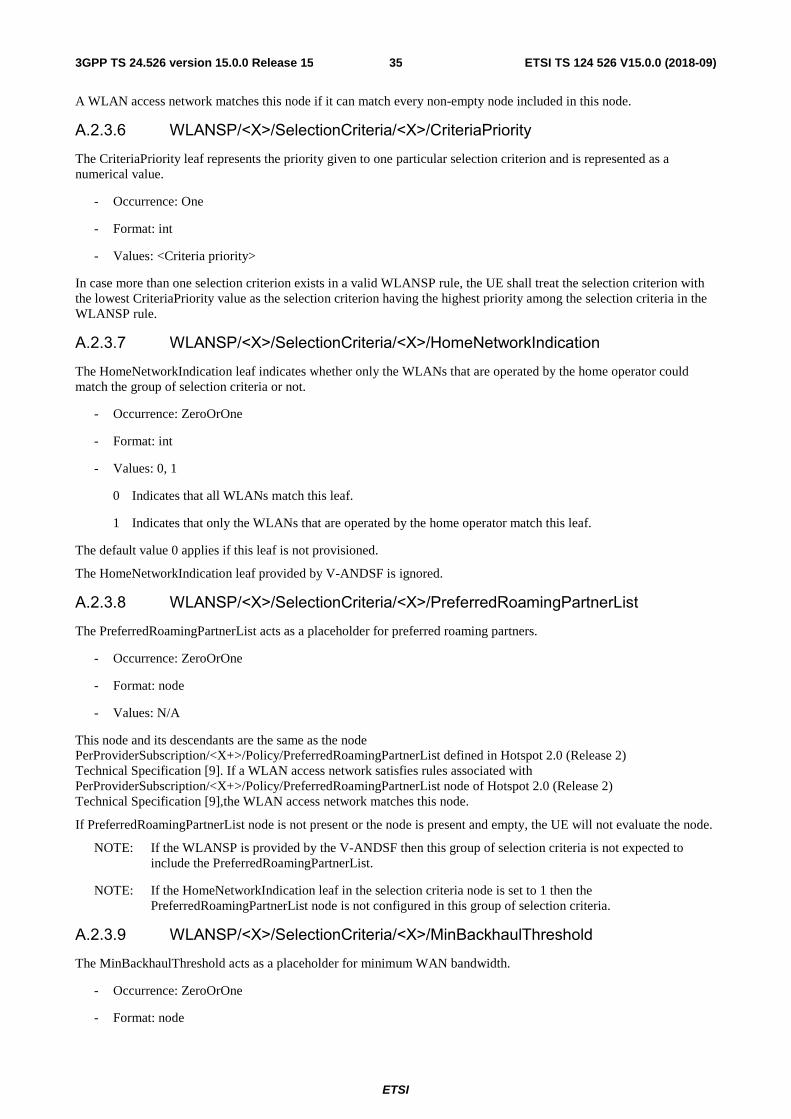
5.3.2.2.4 Home ePDG identifier configuration
The content of home ePDG identifier configuration contains a list of home ePDG identifier entries.
The content of home ePDG identifier configuration is coded according to figure 5.3.2.2.4.1.
The content of each home ePDG identifier entry is coded according to figure 5.3.2.2.4.2, table 5.3.2.2.4.1, figure 5.3.2.2.4.3 and table 5.3.2.2.4.2.
8 7 6 5 4 3 2 1
Home ePDG identifier entry 1 octet w+4 octet u
Home ePDG identifier entry 2
octet u+1 octet m
…
Home ePDG identifier entry n
octet p
Figure 5.3.2.2.4.1: Content of home ePDG identifier configuration
8 7 6 5 4 3 2 1 Home ePDG identifier type (= IP address type) octet 1
Home ePDG IP addresses
octet 2 octet e
Figure 5.3.2.2.4.2: Home ePDG identifier entry (type = IP address type)
ETSI
ETSI TS 124 526 V15.0.0 (2018-09)333GPP TS 24.526 version 15.0.0 Release 15
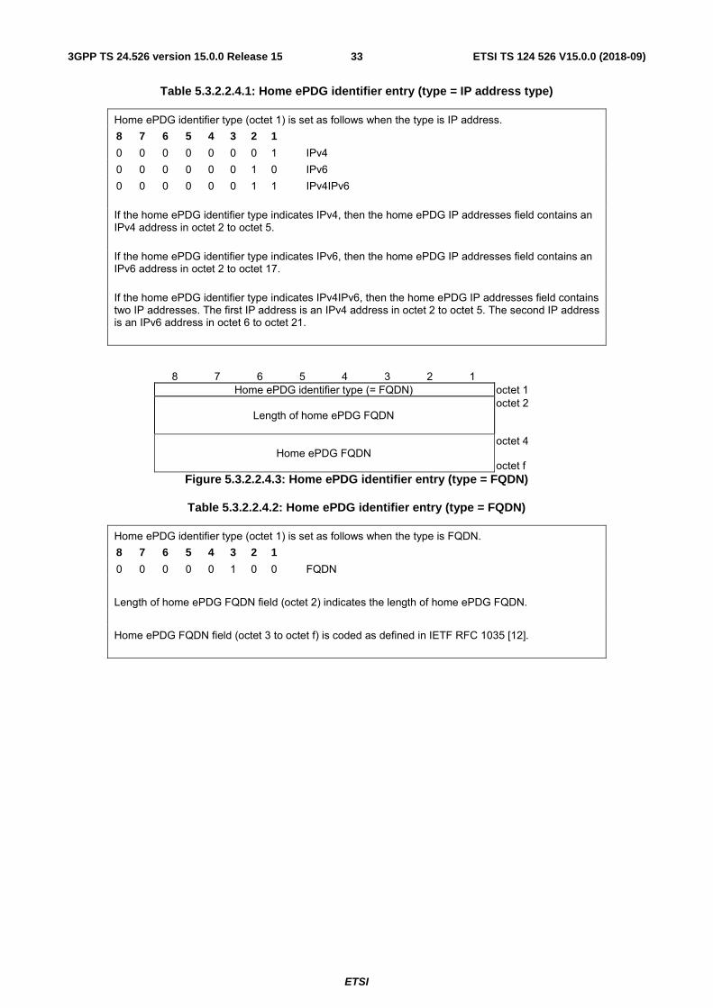
Table 5.3.2.2.4.1: Home ePDG identifier entry (type = IP address type)
Home ePDG identifier type (octet 1) is set as follows when the type is IP address. 8 7 6 5 4 3 2 1 0 0 0 0 0 0 0 1 IPv4 0 0 0 0 0 0 1 0 IPv6 0 0 0 0 0 0 1 1 IPv4IPv6 If the home ePDG identifier type indicates IPv4, then the home ePDG IP addresses field contains an IPv4 address in octet 2 to octet 5. If the home ePDG identifier type indicates IPv6, then the home ePDG IP addresses field contains an IPv6 address in octet 2 to octet 17. If the home ePDG identifier type indicates IPv4IPv6, then the home ePDG IP addresses field contains two IP addresses. The first IP address is an IPv4 address in octet 2 to octet 5. The second IP address is an IPv6 address in octet 6 to octet 21.
8 7 6 5 4 3 2 1 Home ePDG identifier type (= FQDN) octet 1
Length of home ePDG FQDN
octet 2
Home ePDG FQDN
octet 4 octet f
Figure 5.3.2.2.4.3: Home ePDG identifier entry (type = FQDN)
Table 5.3.2.2.4.2: Home ePDG identifier entry (type = FQDN)
Home ePDG identifier type (octet 1) is set as follows when the type is FQDN. 8 7 6 5 4 3 2 1 0 0 0 0 0 1 0 0 FQDN Length of home ePDG FQDN field (octet 2) indicates the length of home ePDG FQDN. Home ePDG FQDN field (octet 3 to octet f) is coded as defined in IETF RFC 1035 [12].
ETSI
ETSI TS 124 526 V15.0.0 (2018-09)343GPP TS 24.526 version 15.0.0 Release 15
Annex A (informative): 5GS N3AN Access Network Discovery and Selection Policy (ANDSP) A.2 WLAN selection policy A.2.3 WLANSP information parameters A.2.3.1 WLANSP
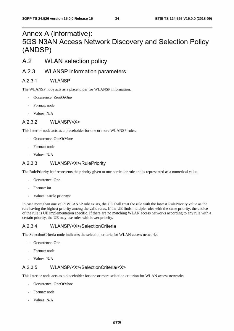
The WLANSP node acts as a placeholder for WLANSP information.
- Occurrence: ZeroOrOne
- Format: node
- Values: N/A
A.2.3.2 WLANSP/<X>
This interior node acts as a placeholder for one or more WLANSP rules.
- Occurrence: OneOrMore
- Format: node
- Values: N/A
A.2.3.3 WLANSP/<X>/RulePriority
The RulePriority leaf represents the priority given to one particular rule and is represented as a numerical value.
- Occurrence: One
- Format: int
- Values: <Rule priority>
In case more than one valid WLANSP rule exists, the UE shall treat the rule with the lowest RulePriority value as the rule having the highest priority among the valid rules. If the UE finds multiple rules with the same priority, the choice of the rule is UE implementation specific. If there are no matching WLAN access networks according to any rule with a certain priority, the UE may use rules with lower priority.
A.2.3.4 WLANSP/<X>/SelectionCriteria
The SelectionCriteria node indicates the selection criteria for WLAN access networks.
- Occurrence: One
- Format: node
- Values: N/A
A.2.3.5 WLANSP/<X>/SelectionCriteria/<X>
This interior node acts as a placeholder for one or more selection criterion for WLAN access networks.
- Occurrence: OneOrMore
- Format: node
- Values: N/A
ETSI
ETSI TS 124 526 V15.0.0 (2018-09)353GPP TS 24.526 version 15.0.0 Release 15
A WLAN access network matches this node if it can match every non-empty node included in this node.
A.2.3.6 WLANSP/<X>/SelectionCriteria/<X>/CriteriaPriority
The CriteriaPriority leaf represents the priority given to one particular selection criterion and is represented as a numerical value.
- Occurrence: One
- Format: int
- Values: <Criteria priority>
In case more than one selection criterion exists in a valid WLANSP rule, the UE shall treat the selection criterion with the lowest CriteriaPriority value as the selection criterion having the highest priority among the selection criteria in the WLANSP rule.
A.2.3.7 WLANSP/<X>/SelectionCriteria/<X>/HomeNetworkIndication
The HomeNetworkIndication leaf indicates whether only the WLANs that are operated by the home operator could match the group of selection criteria or not.
- Occurrence: ZeroOrOne
- Format: int
- Values: 0, 1
0 Indicates that all WLANs match this leaf.
1 Indicates that only the WLANs that are operated by the home operator match this leaf.
The default value 0 applies if this leaf is not provisioned.
The HomeNetworkIndication leaf provided by V-ANDSF is ignored.
A.2.3.8 WLANSP/<X>/SelectionCriteria/<X>/PreferredRoamingPartnerList
The PreferredRoamingPartnerList acts as a placeholder for preferred roaming partners.
- Occurrence: ZeroOrOne
- Format: node
- Values: N/A
This node and its descendants are the same as the node PerProviderSubscription/<X+>/Policy/PreferredRoamingPartnerList defined in Hotspot 2.0 (Release 2) Technical Specification [9]. If a WLAN access network satisfies rules associated with PerProviderSubscription/<X+>/Policy/PreferredRoamingPartnerList node of Hotspot 2.0 (Release 2) Technical Specification [9],the WLAN access network matches this node.
If PreferredRoamingPartnerList node is not present or the node is present and empty, the UE will not evaluate the node.
NOTE: If the WLANSP is provided by the V-ANDSF then this group of selection criteria is not expected to include the PreferredRoamingPartnerList.
NOTE: If the HomeNetworkIndication leaf in the selection criteria node is set to 1 then the PreferredRoamingPartnerList node is not configured in this group of selection criteria.
A.2.3.9 WLANSP/<X>/SelectionCriteria/<X>/MinBackhaulThreshold
The MinBackhaulThreshold acts as a placeholder for minimum WAN bandwidth.
- Occurrence: ZeroOrOne
- Format: node
ETSI
ETSI TS 124 526 V15.0.0 (2018-09)363GPP TS 24.526 version 15.0.0 Release 15
- Values: N/A
This node and its descendants are the same as the node PerProviderSubscription/<X+>/Policy/MinBackhaulThreshold defined in Hotspot 2.0 (Release 2) Technical Specification [9]. If a WLAN access network satisfies rules associated with PerProviderSubscription/<X+>/Policy/MinBackhaulThreshold node of Hotspot 2.0 (Release 2) Technical Specification [9], the WLAN access network matches this node .
If MinBackhaulThreshold node is not present or the node is present and empty, the UE will not evaluate the node.
A.2.3.10 WLANSP/<X>/SelectionCriteria/<X>/MaximumBSSLoadValue
The MaximumBSSLoadValue leaf node acts as a placeholder for maximum BSS load.
- Occurrence: ZeroOrOne
- Format: int
- Values: N/A
This node is the same as the node PerProviderSubscription/<X+>/Policy/MaximumBSSLoadValue defined in Hotspot 2.0 (Release 2) Technical Specification [9]. If a WLAN access network satisfies rules associated with PerProviderSubscription/<X+>/Policy/MaximumBSSLoadValue node of Hotspot 2.0 (Release 2) Technical Specification [9], the WLAN access network matches this node .
If MaximumBSSLoadValue node is not present or the node is present and empty, the UE will not evaluate the node.
A.2.3.11 WLANSP/<X>/SelectionCriteria/<X>/RequiredProtoPortTuple
The RequiredProtoPortTuple acts as a placeholder for IP protocol and destination port tuples.
- Occurrence: ZeroOrOne
- Format: node
- Values: N/A
This node is the same as the node PerProviderSubscription/<X+>/Policy/RequiredProtoPortTuple defined in Hotspot 2.0 (Release 2) Technical Specification [9]. If a WLAN access network satisfies rules associated with PerProviderSubscription/<X+>/Policy/RequiredProtoPortTuple node of Hotspot 2.0 (Release 2) Technical Specification [9], the WLAN access network matches this node.
If RequiredProtoPortTuple node is not present or the node is present and empty, the UE will not evaluate the node.
A.2.3.12 WLANSP/<X>/SelectionCriteria/<X>/SPExclusionList
The SPExclusionList acts as a placeholder for SSIDs not preferred to select.
- Occurrence: ZeroOrOne
- Values: N/A
This node is the same as the node PerProviderSubscription/<X+>/Policy/SPExclusionList defined in Hotspot 2.0 (Release 2) Technical Specification [9]. If a WLAN access network satisfies rules associated with PerProviderSubscription/<X+>/Policy/SPExclusionList node of Hotspot 2.0 (Release 2) Technical Specification [9], the WLAN access network matches this node.
If SPExclusionList node is not present or the node is present and empty, the UE will not evaluate the node.
A.2.3.13 WLANSP/<X>/SelectionCriteria/<X>/PreferredSSIDList
The PreferredSSIDList acts as a placeholder for preferred WLAN access network identifiers.
- Occurrence: ZeroOrOne
- Format: node
- Values: N/A
ETSI
ETSI TS 124 526 V15.0.0 (2018-09)373GPP TS 24.526 version 15.0.0 Release 15
A WLAN access network matches this node if the identifier of the WLAN access network is present in the list specified in this node.
If PreferredSSIDList node is not present or the node is present and empty, the UE will not evaluate the node.
NOTE: If the HomeNetworkIndication in the selection criteria node is set to 1 then the PreferredSSIDList is not configured in this group of selection criteria.
A.2.3.14 WLANSP/<X>/SelectionCriteria/<X>/PreferredSSIDList/<X>
This interior node acts as a placeholder for one or more preferred network identifier for WLAN access network selection.
- Occurrence: OneOrMore
- Format: node
- Values: N/A
A.2.3.15 WLANSP/<X>/SelectionCriteria/<X>/PreferredSSIDList/<X>WLANPriority
The Priority leaf represents the priority given to one particular WLAN and is represented as a numerical value.
- Occurrence: One
- Format: int
- Values: <WLAN priority>
In case more than one WLAN exists in a valid PreferredSSIDList, the WLAN with the lowest Priority value shall be treated as the WLAN having the highest priority among the WLANs in the PreferredSSIDList. If there are multiple WLANs with the same priority, the choice of the WLAN is UE implementation specific.
A.2.3.16 WLANSP/<X>/SelectionCriteria/<X>/PreferredSSIDList/<X>/SSID
The SSID leaf indicates the preferred SSID for WLAN access network selection.
- Occurrence: ZeroOrOne
- Format: chr
- Values: <SSID>
The format of the SSID is defined by IEEE Std 802.11™-2012 [8].
A.2.3.17 WLANSP/<X>/SelectionCriteria/<X>/PreferredSSIDList/<X>/HESSID
The HESSID leaf indicates the preferred HESSID for WLAN access network selection.
- Occurrence: ZeroOrOne
- Format: chr
- Values: <HESSID>
The format of the HESSID is defined by IEEE Std 802.11™-2012 [8].
ETSI
ETSI TS 124 526 V15.0.0 (2018-09)383GPP TS 24.526 version 15.0.0 Release 15
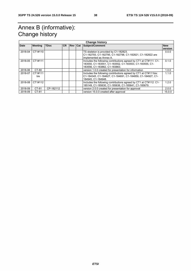
Annex B (informative): Change history
Change history Date Meeting TDoc CR Rev Cat Subject/Comment New
version 2018-04 CT1#110 TS skeleton is provided by C1-182823.
C1-182793, C1-182795, C1-182798, C1-182821, C1-182822 are implemented as Annex A.
0.0.0
2018-05 CT1#111 Includes the following contributions agreed by CT1 at CT#111: C1-183550, C1-183551, C1-183552, C1-183553, C1-183555, C1-183556, C1-183862, C1-183863.
0.1.0
2018-06 CT-80 version 1.0.0 created for presentation for information 1.0.0 2018-07 CT1#111
bis Includes the following contributions agreed by CT1 at CT#111bis:
C1-184345, C1-184627, C1-184691, C1-184859, C1-184927, C1-184945, C1-184948.
1.1.0
2018-08 CT1#112 Includes the following contributions agreed by CT1 at CT#112: C1-185149, C1-185630, C1-185636, C1-185641, C1-185679.
1.2.0
2018-09 CT-81 CP-182112 version 2.0.0 created for presentation for approval 2.0.0 2018-09 CT-81 version 15.0.0 created after approval 15.0.0
ETSI
ETSI TS 124 526 V15.0.0 (2018-09)393GPP TS 24.526 version 15.0.0 Release 15
History Document history
V15.0.0 September 2018 Publication