Embed Size (px)
Citation preview
ETSI TS 143 129 V14.0.0 (2017-04)
Digital cellular telecommunications system (Phase 2+) (GSM); Packet-switched handover for GERAN A/Gb mode;
Stage 2 (3GPP TS 43.129 version 14.0.0 Release 14)
TECHNICAL SPECIFICATION
GLOBAL SYSTEM FOR MOBILE COMMUNICATIONS
R
ETSI
ETSI TS 143 129 V14.0.0 (2017-04)13GPP TS 43.129 version 14.0.0 Release 14
Reference RTS/TSGR-0643129ve00
Keywords GSM
ETSI
650 Route des Lucioles F-06921 Sophia Antipolis Cedex - FRANCE
Tel.: +33 4 92 94 42 00 Fax: +33 4 93 65 47 16
Siret N° 348 623 562 00017 - NAF 742 C
Association à but non lucratif enregistrée à la Sous-Préfecture de Grasse (06) N° 7803/88
Important notice
The present document can be downloaded from: http://www.etsi.org/standards-search
The present document may be made available in electronic versions and/or in print. The content of any electronic and/or print versions of the present document shall not be modified without the prior written authorization of ETSI. In case of any
existing or perceived difference in contents between such versions and/or in print, the only prevailing document is the print of the Portable Document Format (PDF) version kept on a specific network drive within ETSI Secretariat.
Users of the present document should be aware that the document may be subject to revision or change of status. Information on the current status of this and other ETSI documents is available at
https://portal.etsi.org/TB/ETSIDeliverableStatus.aspx
If you find errors in the present document, please send your comment to one of the following services: https://portal.etsi.org/People/CommiteeSupportStaff.aspx
Copyright Notification
No part may be reproduced or utilized in any form or by any means, electronic or mechanical, including photocopying and microfilm except as authorized by written permission of ETSI.
The content of the PDF version shall not be modified without the written authorization of ETSI. The copyright and the foregoing restriction extend to reproduction in all media.
© European Telecommunications Standards Institute 2017.
All rights reserved.
DECTTM, PLUGTESTSTM, UMTSTM and the ETSI logo are Trade Marks of ETSI registered for the benefit of its Members. 3GPPTM and LTE™ are Trade Marks of ETSI registered for the benefit of its Members and
of the 3GPP Organizational Partners. oneM2M logo is protected for the benefit of its Members
GSM® and the GSM logo are Trade Marks registered and owned by the GSM Association.
ETSI
ETSI TS 143 129 V14.0.0 (2017-04)23GPP TS 43.129 version 14.0.0 Release 14
Intellectual Property Rights IPRs essential or potentially essential to the present document may have been declared to ETSI. The information pertaining to these essential IPRs, if any, is publicly available for ETSI members and non-members, and can be found in ETSI SR 000 314: "Intellectual Property Rights (IPRs); Essential, or potentially Essential, IPRs notified to ETSI in respect of ETSI standards", which is available from the ETSI Secretariat. Latest updates are available on the ETSI Web server (https://ipr.etsi.org/).
Pursuant to the ETSI IPR Policy, no investigation, including IPR searches, has been carried out by ETSI. No guarantee can be given as to the existence of other IPRs not referenced in ETSI SR 000 314 (or the updates on the ETSI Web server) which are, or may be, or may become, essential to the present document.
Foreword This Technical Specification (TS) has been produced by ETSI 3rd Generation Partnership Project (3GPP).
The present document may refer to technical specifications or reports using their 3GPP identities, UMTS identities or GSM identities. These should be interpreted as being references to the corresponding ETSI deliverables.
The cross reference between GSM, UMTS, 3GPP and ETSI identities can be found under http://webapp.etsi.org/key/queryform.asp.
Modal verbs terminology In the present document "shall", "shall not", "should", "should not", "may", "need not", "will", "will not", "can" and "cannot" are to be interpreted as described in clause 3.2 of the ETSI Drafting Rules (Verbal forms for the expression of provisions).
"must" and "must not" are NOT allowed in ETSI deliverables except when used in direct citation.
ETSI
ETSI TS 143 129 V14.0.0 (2017-04)33GPP TS 43.129 version 14.0.0 Release 14
Contents
Intellectual Property Rights ................................................................................................................................ 2
Foreword ............................................................................................................................................................. 2
Modal verbs terminology .................................................................................................................................... 2
Foreword ............................................................................................................................................................. 7
Introduction ........................................................................................................................................................ 7
1 Scope ........................................................................................................................................................ 8
2 References ................................................................................................................................................ 8
3 Definitions and abbreviations ................................................................................................................... 9
3.1 Definitions .......................................................................................................................................................... 9
3.2 Void .................................................................................................................................................................. 10
3.3 Abbreviations ................................................................................................................................................... 10
4 Architecture and principles .................................................................................................................... 12
4.1 Reference architecture ...................................................................................................................................... 12
4.2 Handover principles ......................................................................................................................................... 12
4.2.1 General ........................................................................................................................................................ 12
4.2.2 PS Handover preparation phase .................................................................................................................. 13
4.2.3 PS Handover execution phase ..................................................................................................................... 14
4.2.4 PS Handover Network Node Responsibilities ............................................................................................ 14
4.3 Protocol architecture......................................................................................................................................... 14
4.3.1 User plane overview ................................................................................................................................... 14
4.3.2 Control plane overview ............................................................................................................................... 14
4.3.3 Physical Layer ............................................................................................................................................ 15
4.3.3.1 Shared Channels .................................................................................................................................... 15
4.3.3.1.1 General ............................................................................................................................................ 15
4.3.4 RLC/MAC .................................................................................................................................................. 15
4.3.5 Radio Resource (RR) .................................................................................................................................. 16
4.3.6 BSSGP ........................................................................................................................................................ 16
4.3.7 Overview of PS Handover Signalling Messages ........................................................................................ 16
4.3.7.1 PS handover signalling messages on the Um interface ......................................................................... 16
4.3.7.2 PS handover signalling messages on the Gb interface .......................................................................... 16
4.3.7.3 PS handover signalling messages on the Gn interface .......................................................................... 17
4.3.7.4 PS handover signalling messages on the Up interface .......................................................................... 18
4.4 Identifiers ......................................................................................................................................................... 18
4.4.1 NSAPI, PFI, RAB ID relation during inter-RAT, inter-mode UTRAN/GERAN Iu PS handover ............. 19
4.4.2 NSAPI, PFI, EPS Bearer ID relation during inter-RAT GERAN / E-UTRAN PS handover .................... 20
5 Signalling procedures ............................................................................................................................. 20
5.1 GERAN (A/Gb mode) � GERAN (A/Gb mode) handover ............................................................................. 20
5.1.1 Intra Cell ..................................................................................................................................................... 20
5.1.2 Intra BSS ..................................................................................................................................................... 21
5.1.2.1 General .................................................................................................................................................. 21
5.1.2.2 Intra BSS HO; Preparation phase .......................................................................................................... 21
5.1.2.3 Intra BSS HO; Execution phase ............................................................................................................ 22
5.1.2.4 Intra BSS Handover - Optimised .......................................................................................................... 23
5.1.3 Intra SGSN.................................................................................................................................................. 25
5.1.3.1 Intra SGSN/Inter BSS HO, Preparation phase ...................................................................................... 25
5.1.3.2 Intra SGSN/Inter BSS HO, Execution phase ........................................................................................ 26
5.1.4 Inter SGSN.................................................................................................................................................. 28
5.1.4.1 Inter SGSN HO, Preparation phase ....................................................................................................... 28
5.1.4.2 Inter SGSN HO, Execution phase ......................................................................................................... 31
5.2 Inter-RAT/mode handover (GERAN A/Gb mode � UTRAN/ GERAN Iu mode) ......................................... 35
5.2.1 Intra SGSN.................................................................................................................................................. 35
5.2.1.1 Intra-SGSN GERAN A/Gb mode to UTRAN/GERAN Iu mode HO; Preparation phase ..................... 35
ETSI
ETSI TS 143 129 V14.0.0 (2017-04)43GPP TS 43.129 version 14.0.0 Release 14
5.2.1.2 Intra-SGSN GERAN A/Gb mode to UTRAN/GERAN Iu mode HO; Execution phase ....................... 37
5.2.2 Inter SGSN.................................................................................................................................................. 40
5.2.2.1 Inter-SGSN GERAN A/Gb mode to UTRAN/GERAN Iu mode HO; Preparation phase ..................... 40
5.2.2.2 Inter-SGSN GERAN A/Gb mode to UTRAN/GERAN Iu mode HO; Execution phase ....................... 42
5.3 Inter-RAT/mode Handover (UTRAN/GERAN Iu mode � GERAN A/Gb mode).......................................... 46
5.3.1 Intra SGSN.................................................................................................................................................. 46
5.3.1.1 Inter RAT/mode UTRAN/GERAN Iu mode to GERAN A/Gb mode PS HO; Preparation phase ........ 46
5.3.1.2 Inter RAT/mode UTRAN/GERAN Iu mode to GERAN A/Gb mode PS HO; Execution phase .......... 48
5.3.2 Inter SGSN.................................................................................................................................................. 51
5.3.2.1 Inter RAT/mode UTRAN/GERAN Iu mode to GERAN A/Gb mode PS HO; Preparation phase ........ 51
5.3.2.2 Inter RAT UTRAN/GERAN Iu mode to GERAN A/Gb mode PS HO; Execution phase .................... 53
5.3a Inter-RAT Handover (GERAN A/Gb mode to E-UTRAN) .............................................................................. 56
5.3a.1 General ........................................................................................................................................................ 56
5.3a.2 Preparation phase ........................................................................................................................................ 56
5.3a.3 Execution phase .......................................................................................................................................... 57
5.3b Inter-RAT Handover (E-UTRAN to GERAN A/Gb mode) .............................................................................. 57
5.3b.1 General ........................................................................................................................................................ 57
5.3b.2 Preparation phase ........................................................................................................................................ 57
5.3b.3 Execution phase .......................................................................................................................................... 57
5.4 Handover reject ................................................................................................................................................ 58
5.4.1 General ........................................................................................................................................................ 58
5.4.2 Inter-SGSN HO Reject; Signalling procedure ............................................................................................ 58
5.5 Handover cancel ............................................................................................................................................... 58
5.5.1 General ........................................................................................................................................................ 58
5.5.2 Signalling procedures ................................................................................................................................. 59
5.5.2.1 Inter-SGSN case, GERAN A/Gb mode� GERAN A/Gb mode .......................................................... 59
5.5.2.2 Inter-SGSN case, GERAN A/Gb mode� UTRAN/GERAN Iu mode ................................................. 60
5.5.2.3 Inter-SGSN case, UTRAN/GERAN Iu mode� GERAN A/Gb mode ................................................. 61
5.5.2.4 Inter-SGSN, GERAN A/Gb mode � E-UTRAN ................................................................................. 61
5.5.2.5 Inter-SGSN case, E - UTRAN� GERAN A/Gb mode ........................................................................ 61
5.6 Container handling ........................................................................................................................................... 61
5.6.1 Contents of the containers ........................................................................................................................... 63
5.6.1.1 Contents of the GERAN A/Gb mode or GAN mode → GERAN A/Gb mode Transparent Containers ............................................................................................................................................. 64
5.6.1.1.1 Source BSS to Target BSS Transparent Container .......................................................................... 64
5.6.1.1.2 Target BSS to Source BSS Transparent Container .......................................................................... 64
5.6.1.2 Contents of the GERAN A/Gb mode or GAN mode → UTRAN Transparent Containers................... 64
5.6.1.2.1 Source to Target Transparent Container .......................................................................................... 64
5.6.1.2.2 Target to Source Transparent Container .......................................................................................... 65
5.6.1.3 Contents of the UTRAN → GERAN A/Gb Mode or GAN mode Transparent Containers .................. 65
5.6.1.3.1 Source BSS to Target BSS Transparent Container .......................................................................... 65
5.6.1.3.2 Target BSS to Source BSS Transparent Container .......................................................................... 65
5.6.1.4 Contents of the GERAN A/Gb mode → GERAN Iu mode Transparent Containers ............................ 66
5.6.1.4.1 Source to Target Transparent Container .......................................................................................... 66
5.6.1.4.2 Target to Source Transparent Container .......................................................................................... 66
5.6.1.5 Content of GERAN Iu mode → GERAN A/Gb mode Transparent Containers ................................... 66
5.6.1.5.1 Source BSS to Target BSS Transparent Container .......................................................................... 66
5.6.1.5.2 Target BSS to Source BSS Transparent Container .......................................................................... 66
5.6.1.6 Contents of the GERAN A/Gb mode → GAN mode Transparent Containers ..................................... 67
5.6.1.6.1 Source BSS to Target BSS Transparent Container .......................................................................... 67
5.6.1.6.2 Target BSS to Source BSS Transparent Container .......................................................................... 67
5.6.1.7 Contents of the GERAN A/Gb mode → E-UTRAN Transparent Containers ...................................... 67
5.6.1.7.1 Source to Target Transparent Container ........................................................................................ 67
5.6.1.7.2 Target to Source Transparent Container ........................................................................................ 67
5.6.1.8 Contents of the E-UTRAN → GERAN A/Gb mode Transparent Containers ...................................... 68
5.6.1.8.1 Source BSS to Target BSS Transparent Container .......................................................................... 68
5.6.1.8.2 Target BSS to Source BSS Transparent Container .......................................................................... 68
5.7 PS Handover Failure ........................................................................................................................................ 68
5.7.1 Preparations Phase Failure Scenarios ......................................................................................................... 69
5.7.1.1 PS Handover preparation phase failure scenarios on the Um interface ................................................. 69
5.7.1.2 PS Handover preparation phase failure scenarios on the Gb interface .................................................. 69
5.7.1.3 PS Handover preparation phase failure scenarios on the Gn interface .................................................. 69
ETSI
ETSI TS 143 129 V14.0.0 (2017-04)53GPP TS 43.129 version 14.0.0 Release 14
5.7.1.4 PS Handover preparation phase failure scenarios on the Up interface .................................................. 69
5.7.2 Execution Phase Failure Scenarios ............................................................................................................. 70
5.7.2.1 Execution phase failures on the Um interface ....................................................................................... 70
5.7.2.1.1 Initial Access Failure in the Target Cell during PS handover.......................................................... 70
5.7.2.1.2 Radio contact with the MS is lost: ................................................................................................... 71
5.7.2.2 Execution phase failures on the Gb interface ........................................................................................ 73
5.7.2.3 Execution phase failures on the Gn interface ........................................................................................ 74
5.8 GAN Handover ................................................................................................................................................ 74
5.8.1 Intra-SGSN Handover (GERAN A/Gb mode � GAN mode handover) .................................................... 74
5.8.1.1 Intra SGSN PS Handover, Preparation phase ....................................................................................... 74
5.8.1.2 Intra SGSN PS Handover, Execution phase .......................................................................................... 75
5.8.2 Intra-SGSN Handover (GAN mode � GERAN A/Gb mode handover).................................................... 75
5.8.2.1 Intra SGSN PS Handover, Preparation phase ....................................................................................... 75
5.8.2.2 Intra SGSN PS Handover, Execution phase .......................................................................................... 76
5.8.3 Inter-SGSN Handover (GERAN A/Gb mode � GAN mode handover) .................................................... 76
5.8.3.1 Inter SGSN PS Handover, Preparation phase ....................................................................................... 76
5.8.3.2 Inter SGSN PS Handover, Execution phase .......................................................................................... 76
5.8.4 Inter-SGSN Handover (GAN mode � GERAN A/Gb mode handover).................................................... 76
5.8.4.1 Inter SGSN PS Handover, Preparation phase ....................................................................................... 76
5.8.4.2 Inter SGSN, Execution phase ................................................................................................................ 77
5.8.5 Inter RAT Handover; Intra SGSN (UTRAN � GAN mode handover) ..................................................... 77
5.8.5.1 Intra SGSN PS Handover, Preparation phase ....................................................................................... 77
5.8.5.2 Intra SGSN PS Handover, Execution phase .......................................................................................... 78
5.8.6 Inter RAT Handover; Intra SGSN (GAN mode �UTRAN handover) ...................................................... 78
5.8.6.1 Intra SGSN PS Handover, Preparation phase ....................................................................................... 78
5.8.6.2 Intra SGSN, Execution phase ................................................................................................................ 78
5.8.7 Inter RAT Handover; Inter SGSN (UTRAN � GAN mode handover) ..................................................... 79
5.8.7.1 Inter SGSN PS Handover, Preparation phase ....................................................................................... 79
5.8.7.2 Inter SGSN PS Handover, Execution phase .......................................................................................... 79
5.8.8 Inter RAT Handover; Inter SGSN (GAN mode � UTRAN handover) ..................................................... 79
5.8.8.1 Inter SGSN PS Handover, Preparation phase ....................................................................................... 79
5.8.8.2 Inter SGSN PS Handover, Execution phase .......................................................................................... 79
6 Radio interface Signalling ...................................................................................................................... 79
6.1 PS Handover Signalling (Um) .......................................................................................................................... 79
6.1.1 General ........................................................................................................................................................ 79
6.1.2 Overview of PS Handover messages .......................................................................................................... 80
6.1.2.1 GERAN A/Gb mode/GAN mode to GERAN A/Gb mode PS Handover ............................................. 80
6.1.2.2 UTRAN/GERAN Iu mode to GERAN A/Gb mode/GAN mode PS Handover .................................... 80
6.1.2.3 GERAN A/Gb mode to GERAN Iu mode PS Handover ...................................................................... 81
6.1.2.4 GERAN A/Gb mode/GAN mode to UTRAN mode PS Handover ....................................................... 82
6.1.2.5 GERAN A/Gb mode to GAN mode PS Handover ................................................................................ 82
6.1.2.6 GERAN A/Gb mode to E-UTRAN PS Handover ................................................................................. 82
6.1.2.7 E-UTRAN to GERAN A/Gb mode PS Handover ................................................................................. 83
6.1.3 RLC/MAC segmentation ............................................................................................................................ 83
6.1.4 Inter RAT/mode PS Handover to GERAN A/Gb ....................................................................................... 83
6.1.5 Inter RAT/mode PS Handover from GERAN A/Gb ................................................................................... 83
6.2 Mechanisms for Initial Access in the Target Cell ............................................................................................ 83
6.2.1 General ........................................................................................................................................................ 83
6.2.2 Synchronisation of handovers ..................................................................................................................... 84
6.2.3 Option 1 - Downlink Data sent after performing access in the target cell .................................................. 84
6.2.3.1 Unsynchronised Networks Call Flow.................................................................................................... 84
6.2.3.2 Synchronised Networks Call Flow ........................................................................................................ 85
6.2.4 Option 2 - Downlink Data sent before performing access in the target cell (Blind Transmission) ............ 85
6.2.4.1 Unsynchronised Networks Call Flow.................................................................................................... 86
6.2.4.2 Synchronised Network Call Flow ......................................................................................................... 86
6.3 Methods for triggering PS Handover................................................................................................................ 87
Annex A (normative): Agreed handover principles .......................................................................... 88
A.1 Agreed handover principles .................................................................................................................... 88
Annex B (informative): PS Handover Primitives ................................................................................ 90
ETSI
ETSI TS 143 129 V14.0.0 (2017-04)63GPP TS 43.129 version 14.0.0 Release 14
B.1 Overview ................................................................................................................................................ 90
B.2 Primitives in Source BSS ....................................................................................................................... 90
B.3 Primitives in Old SGSN ......................................................................................................................... 91
B.4 Primitives in New SGSN ........................................................................................................................ 92
B.5 Primitives in Target BSS ........................................................................................................................ 93
B.6 Primitives in MS ..................................................................................................................................... 93
Annex C (informative): Change history ............................................................................................... 94
History .............................................................................................................................................................. 97
ETSI
ETSI TS 143 129 V14.0.0 (2017-04)73GPP TS 43.129 version 14.0.0 Release 14
Foreword This Technical Specification has been produced by the 3rd Generation Partnership Project (3GPP).
The contents of the present document are subject to continuing work within the TSG and may change following formal TSG approval. Should the TSG modify the contents of the present document, it will be re-released by the TSG with an identifying change of release date and an increase in version number as follows:
Version x.y.z
where:
x the first digit:
1 presented to TSG for information;
2 presented to TSG for approval;
3 or greater indicates TSG approved document under change control.
y the second digit is incremented for all changes of substance, i.e. technical enhancements, corrections, updates, etc.
z the third digit is incremented when editorial only changes have been incorporated in the document.
Introduction Packet Switched (PS) handover is introduced in order to support real-time packet-switched with strict QoS requirements on low latency and packet loss. Packet switched handover reduces the service interruption of the user plane information at cell change compared to the cell-reselection and enables methods to improve buffer handling of user plane data in order to reduce packet loss at cell-change.
ETSI
ETSI TS 143 129 V14.0.0 (2017-04)83GPP TS 43.129 version 14.0.0 Release 14
1 Scope The present document defines the stage-2 service description for packet switched handover in GERAN A/Gb mode and GAN mode. ITU-T Recommendation I.130 [8] describes a three-stage method for characterisation of telecommunication services, and ITU-T Recommendation Q.65 [9] defines stage 2 of the method. The present document refers to packet switched handover in GERAN A/Gb mode/GAN mode, and therefore focuses on the corresponding radio protocol enhancements to the packet switched domain only i.e. when services are provided through the Gb interface.
2 References The following documents contain provisions which, through reference in this text, constitute provisions of the present document.
• References are either specific (identified by date of publication, edition number, version number, etc.) or non-specific.
• For a specific reference, subsequent revisions do not apply.
• For a non-specific reference, the latest version applies. In the case of a reference to a 3GPP document (including a GSM document), a non-specific reference implicitly refers to the latest version of that document in the same Release as the present document.
[1] 3GPP TR 21.905: "Vocabulary for 3GPP Specifications".
[2] 3GPP TS 22.105: "Services and service capabilities".
[3] 3GPP TS 22.060: "General Packet Radio Service (GPRS); Service description; Stage 1".
[4] 3GPP TS 43.064: "Overall description of the GPRS radio interface; Stage 2".
[5] 3GPP TS 25.922: "Radio Resource Management strategies".
[6] 3GPP TS 23.107: "Quality of Service (QoS) concept and architecture".
[7] 3GPP TS 44.060: "General Packet Radio Service (GPRS); Mobile Station (MS) - Base Station System (BSS) interface; Radio Link Control/Medium Access Control (RLC/MAC) protocol".
[8] ITU-T Recommendations I.130: "Method for the characterization of telecommunication services supported by an ISDN and network capabilities of an ISDN".
[9] ITU-T Recommendation Q.65: "The unified functional methodology for the characterization of services and network capabilities".
[10] 3GPP TS 48.018: "General Packet Radio Service (GPRS); Base Station System (BSS) - Serving GPRS Support Node (SGSN); BSS GPRS Protocol".
[11] 3GPP TS 29.060: "General Packet Radio Service (GPRS); GPRS Tunnelling Protocol (GTP) across the Gn and Gp interface".
[12] 3GPP TS 23.003: "Numbering, addressing and identification".
[13] 3GPP TS 25.401: "UTRAN overall description".
[14] 3GPP TS 43.051: "GSM/EDGE Radio Access Network (GERAN) overall description; Stage 2".
[15] 3GPP TS 24.008: "Mobile radio interface Layer 3 specification; Core network protocols; Stage 3".
[16] 3GPP TS 44.118: "Mobile radio interface layer 3 specification, Radio Resource Control (RRC) protocol; Iu mode".
[17] 3GPP TS 25.331: "Radio Resource Control (RRC) protocol specification".
ETSI
ETSI TS 143 129 V14.0.0 (2017-04)93GPP TS 43.129 version 14.0.0 Release 14
[18] 3GPP TS 24.007: "Mobile radio interface signalling layer 3; General Aspects".
[19] 3GPP TS 23.060: "General Packet Radio Service (GPRS); Service description; Stage 2".
[20] 3GPP TS 23.108: "Mobile radio interface layer 3 specification core network protocols; Stage 2 (structured procedures)".
[21] 3GPP TS 44.064: "Mobile Station - Serving GPRS Support Node (MS-SGSN) Logical Link Control (LLC) Layer Specification".
[22] 3GPP TS 23.236: "Intra-domain connection of Radio Access Network (RAN) nodes to multiple Core Network (CN) nodes".
[23] 3GPP TS 25.413: "UTRAN Iu interface Radio Access Network Application Part (RANAP) signalling".
[24] Void.
[25] 3GPP TS 44.018: "Mobile radio interface layer 3 specification; Radio Resource Control (RRC) protocol".
[26] 3GPP TS 45.010: "Radio subsystem synchronization".
[27] 3GPP TS 33.102: “Security architecture”.
[28] 3GPP TS 44.318: “Generic access to the A/Gb interface; Mobile GA interface layer 3 specification”.
[29] 3GPP TS 43.318: “Generic access to the A/Gb interface; Stage 2”.
[30] 3GPP TS 36.300: “Evolved Universal Terrestrial Radio Access (E-UTRA) and Evolved Universal Terrestrial Radio Access (E-UTRAN); Overall description; Stage 2”.
[31] 3GPP TS 36.331:” Evolved Universal Terrestrial Radio Access (E-UTRA); Radio Resource Control (RRC); Protocol specification”.
[32] 3GPP TS 36.401: “Evolved Universal Terrestrial Radio Access Network (E-UTRAN); Architecture description”.
[33] 3GPP TS 23.401: “General Packet Radio Service (GPRS) enhancements for Evolved Universal Terrestrial Radio Access Network (E-UTRAN) access”.
[34] 3GPP TS 36.413: "Evolved Universal Terrestrial Radio Access (E-UTRA); S1 Application Protocol (S1AP)".
[35] 3GPP TS 24.301: “Non-Access-Stratum (NAS) protocol for Evolved Packet System (EPS); Stage 3”.
[36] 3GPP TS 22.220: "Service requirements for Home NodeBs and Home eNodeBs".
3 Definitions and abbreviations
3.1 Definitions For the purposes of the present document, the terms and definitions given in 3GPP TR 21.905 [1] and the following apply:
Active PFCs: that subset of the PFCs to be handed over, for which the source BSS has determined that resources should be allocated in the target cell during the PS Handover preparation phase.
A/Gb mode: MS mode operation where the MS is connected to the Core Network via GERAN and the A and/or Gb interfaces.
ETSI
ETSI TS 143 129 V14.0.0 (2017-04)103GPP TS 43.129 version 14.0.0 Release 14
Blind Transmission: refers to the decision made by the SGSN to start the transmission of downlink N-PDUs or by the target BSS/GANC to start the transmission of downlink LLC PDUs for a given mobile station before receiving confirmation that the PS handover procedure has been successfully completed.
GAN Mode: MS mode of operation where the MS is connected to the Core Network via a GANC and the A and/or Gb interfaces.
PFC subject to handover: refers to an MS’s PFC for which the packet switched handover procedure is to be initiated when a cell change is required. Whether a PFC needs handover or not is decided by the BSS. This decision criteria is not standardized.
Source to Target Transparent Container: This container is encoded as "Source RNC to Target RNC transparent container" in case of PS handover to UTRAN and as "Source eNB to Target eNB transparent container" in case of PS handover to E-UTRAN. It replaces the "Source RNC to Target RNC Transparent container" used in previous releases.
Target to Source Transparent Container: This container is encoded as "Target RNC to Source RNC transparent container" in case of PS handover to UTRAN and as "Target eNB to Source eNB transparent container" in case of PS handover to E-UTRAN. It replaces the "Target RNC to Source RNC Transparent container" used in previous releases.
CSG Cell: A UTRAN or E-UTRAN cell for which the reported access mode indicates "Closed access mode" (see [36]).
Hybrid Cell: A UTRAN or E-UTRAN cell for which the reported access mode indicates "Hybrid access mode" (see [36]).
3.2 Void
3.3 Abbreviations For the purposes of the present document, the following abbreviations apply:
ATM Asynchronous Transfer Mode BSC Base Station Controller BSS Base Station Sub-system BSSGP Base Station Subsystem GPRS Protocol BTS Base Transceiver Station CN part Core Network part CN Core Network CS Circuit Switched CSG Closed Subscriber Group DTI Direct Tunnel Indicator DTM Dual Transfer Mode EDGE Enhanced Data rates for GSM Evolution eNB E-UTRAN NodeB EPC Evolved Packet Core EPS Evolved Packet System E-UTRA Evolved UTRA E-UTRAN Evolved UTRAN FLO Flexible Layer One GAN Generic Access Network GANC Generic Access Network Controller GboIP Gb over IP GCSI GPRS CAMEL Subscriber information indicator GERAN GSM/EDGE Radio Access Network GPRS General Packet Radio Service GSM Global System for Mobile communications GTP GPRS Tunnelling Protocol IMS IP Multimedia Subsystem IP Internet Protocol LLC Logical Link Control MAC Medium Access Control MME Mobility Management Entity
ETSI
ETSI TS 143 129 V14.0.0 (2017-04)113GPP TS 43.129 version 14.0.0 Release 14
MS Mobile Station MSC Mobile Switching Centre MTU Maximum Transfer Unit PDP Packet Data Protocol PDTCH Packet Data Traffic CHannel PFC Packet Flow Context PFM Packet Flow Management PS Packet Switched PTCCH Packet Timing advance Control CHannel QoS Quality of Service RAB Radio Access Bearer RAN Radio Access Network RAT Radio Access Technology RAU Routeing Area Update RLC Radio Link Control RN part Radio Network part RNC Radio Network Controller RNS Radio Network Subsystem ROHC RObust Header Compression RRM Radio Resource Management RTP Real Time Protocol SABM Set Asynchronous Balanced Mode SACCH Standalone Associated Control CHannel SAPI Service Access Point Identifier SGSN Serving GPRS Support Node S-GW Serving Gateway SIP Session Initiated Protocol SNDCP Sub-Network Dependent Convergence Protocol TBF Temporary Block Flow TF Transport Format TFC Transport Format Combination TFCI Transport Format Combination Indicator TR Technical Report TS Technical Specification UA Unnumbered Acknowledgement UDP User Datagram Protocol UE User Equipment UMTS Universal Mobile Telephony System UTRAN UMTS Terrestrial Radio Access Network VoIP Voice over IP XID eXchange IDentification
ETSI
ETSI TS 143 129 V14.0.0 (2017-04)123GPP TS 43.129 version 14.0.0 Release 14
4 Architecture and principles
4.1 Reference architecture
MME
eNB
S4
S1- MME
Uu
Um
S-GW
S11
S3
E-UTRAN
S4
Gs
IuPS
S3
CN
UTRAN BSS/GERAN
IuCS
Gb
S12
S5/S8
S1- Uu
Gn or S16
Gn/Gp
BSC
MS
MSC SGSN
Gn/Gp
BTS BTS
Abis
PSTN
A Gb
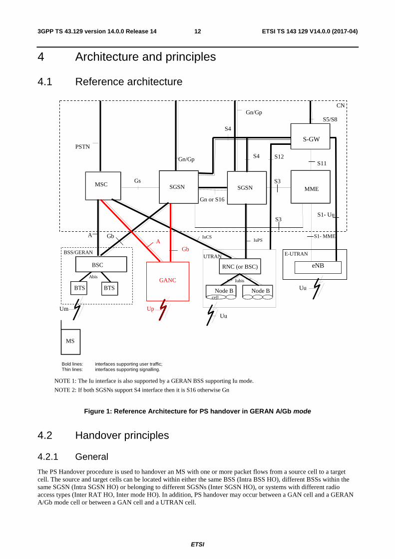
Bold lines: interfaces supporting user traffic; Thin lines: interfaces supporting signalling.
NOTE 1: The Iu interface is also supported by a GERAN BSS supporting Iu mode.
NOTE 2: If both SGSNs support S4 interface then it is S16 otherwise Gn
RNC (or BSC)
Node B Node B
Iubis
cell
Uu
SGSN
GANC
Up
A
Figure 1: Reference Architecture for PS handover in GERAN A/Gb mode
4.2 Handover principles
4.2.1 General
The PS Handover procedure is used to handover an MS with one or more packet flows from a source cell to a target cell. The source and target cells can be located within either the same BSS (Intra BSS HO), different BSSs within the same SGSN (Intra SGSN HO) or belonging to different SGSNs (Inter SGSN HO), or systems with different radio access types (Inter RAT HO, Inter mode HO). In addition, PS handover may occur between a GAN cell and a GERAN A/Gb mode cell or between a GAN cell and a UTRAN cell.
ETSI
ETSI TS 143 129 V14.0.0 (2017-04)133GPP TS 43.129 version 14.0.0 Release 14
While the MS is still in the source cell:
• Radio resources in the target cell are allocated and signalled to the MS.
• System information of the target cell needed for access in the target cell is signalled to the MS.
For each scenario (Intra BSS HO, Intra SGSN HO, Inter SGSN HO, Inter RAT HO/Inter mode HO) the PS handover procedure is divided into:
• a preparation phase; and
• an execution phase.
By using the Gs interface (together with NMO1) the interruption time for the PS Handover procedure would be shortened since using a combined LAU/RAU procedure would be possible.
The scenarios described in the remainder of sub-clause 4.2 are limited to the case where an MS is being served by a BSS in GERAN A/Gb mode when a PS handover becomes necessary.
4.2.2 PS Handover preparation phase
The PS handover preparation phase consists of the following consecutive steps:
• the decision by the source BSS to request a PS handover for an MS with one or more PFCs subject to handover:
- the request from the source BSS to the old SGSN for the PS handover;
- if the target BSS/GANC is not connected to the same SGSN the request from the old SGSN to the new SGSN to reserve resources;
• the reservation of resources in the target network nodes prior to ordering the MS to move to the target cell. This involves:
- in case of Inter SGSN handover, the new SGSN reserving SNDCP/LLC resources and establishing Packet Flow Contexts;
- in case of RA change the SGSN (which belongs to the RA) allocates a new P-TMSI and derives a new Local TLLI from this P-TMSI;
- the target BSS/GANC reserving/allocating radio resources and Packet Flow Contexts in the target cell or the target RNS reserving/allocating radio resources and RABs in the target cell;
- in case of Inter-SGSN handover, the definition of security related parameters for the new SGSN, e.g. ciphering algorithm, to be used in the target cell immediately in both uplink and downlink directions.
When PS handover has to be performed for an MS with multiple active PFCs, the SGSN requests the target BSS/GANC to create one or more PFCs or the target RNS to create one or more RABs corresponding to the active PFCs:
• The target BSS/GANC may or may not establish radio resources for the created PFCs and the target RNS may or may not allocate resources for all the requested RABs. If no radio resources at all are established the handover shall be rejected (see Section 5.4.2).
• If not all the PFCs can be created successfully the target BSS/GANC indicates this to the new SGSN, which then informs the old SGSN/source BSS on the accepted and failed BSS PFCs.
• If not all the RABs can be allocated the target RNS indicates this to the new SGSN, which then informs the old SGSN/source BSS on the accepted and failed BSS PFCs.
• PFCs for which no radio resources were reserved in the target BSS or for which no RABs were allocated in the target RNS will result in the establishment of the necessary radio resources upon MS arrival in the target cell. For the case of PS handover to GAN the target GANC shall either create all requested PFCs or none.
ETSI
ETSI TS 143 129 V14.0.0 (2017-04)143GPP TS 43.129 version 14.0.0 Release 14
4.2.3 PS Handover execution phase
The PS Handover execution phase consists of the following consecutive steps:
• packet forwarding by the old SGSN of the received DL packets both to the source BSS, new SGSN (if the PS handover involves a new SGSN) and the target BSS/GANC/RNS as soon as radio resources are reserved in the target BSS/GANC/RNS;
• the optional "blind" transmission by the target BSS/GANC of the DL RLC/MAC blocks/LLC PDUs over the reserved radio resources in the target cell is only valid for lossy type of services where unacknowledged LLC and RLC protocol modes are used;
• the command generated by the target BSS/GANC/RNS sent via the source BSS to order the MS to handover to the target cell;
• the notification by the MS of its presence in the target cell on the allocated radio resources;
• the redirection by the SGSN of the DL packets to the target BSS/GANC/RNS alone;
• the release of the resources on the source side including PFCs and radio resources.
4.2.4 PS Handover Network Node Responsibilities
This clause would reflect the Agreed Handover principles from the clause A.1 by listing the specific node responsibilities during PS handover.
4.3 Protocol architecture This clause will contain information on the services and functions provided and required by each layer.
4.3.1 User plane overview
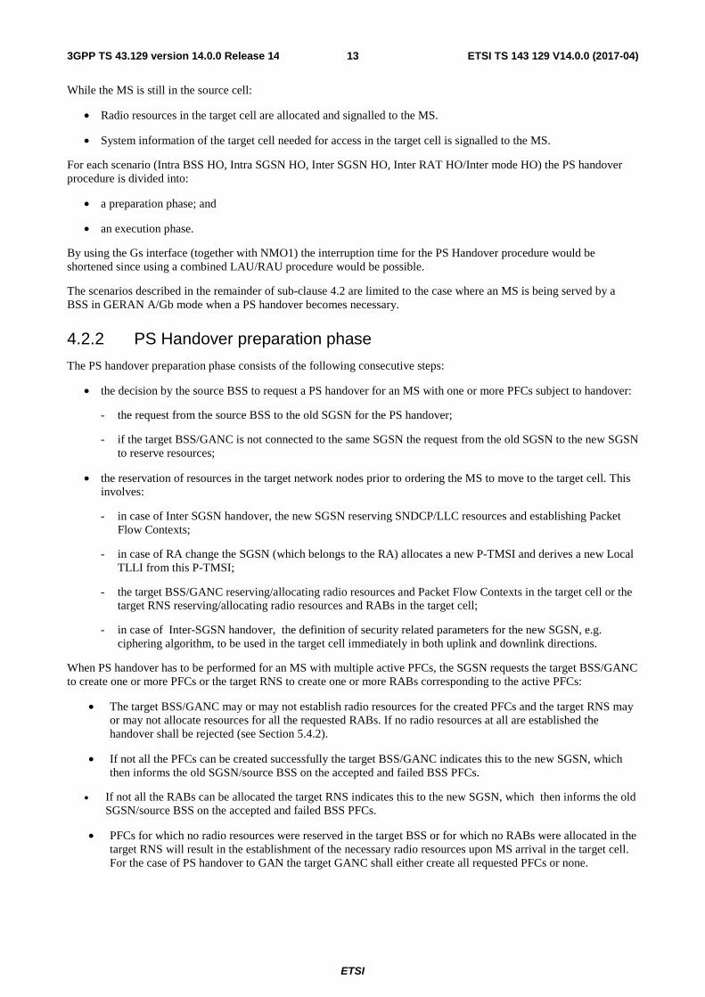
The user plane protocol architecture for GERAN A/Gb mode is depicted in figure 2. See 3GPP TS 43.318 [29] for the user plane protocol architecture applicable for GAN mode.
Figure 2: User Plane protocol architecture in A/Gb mode
4.3.2 Control plane overview
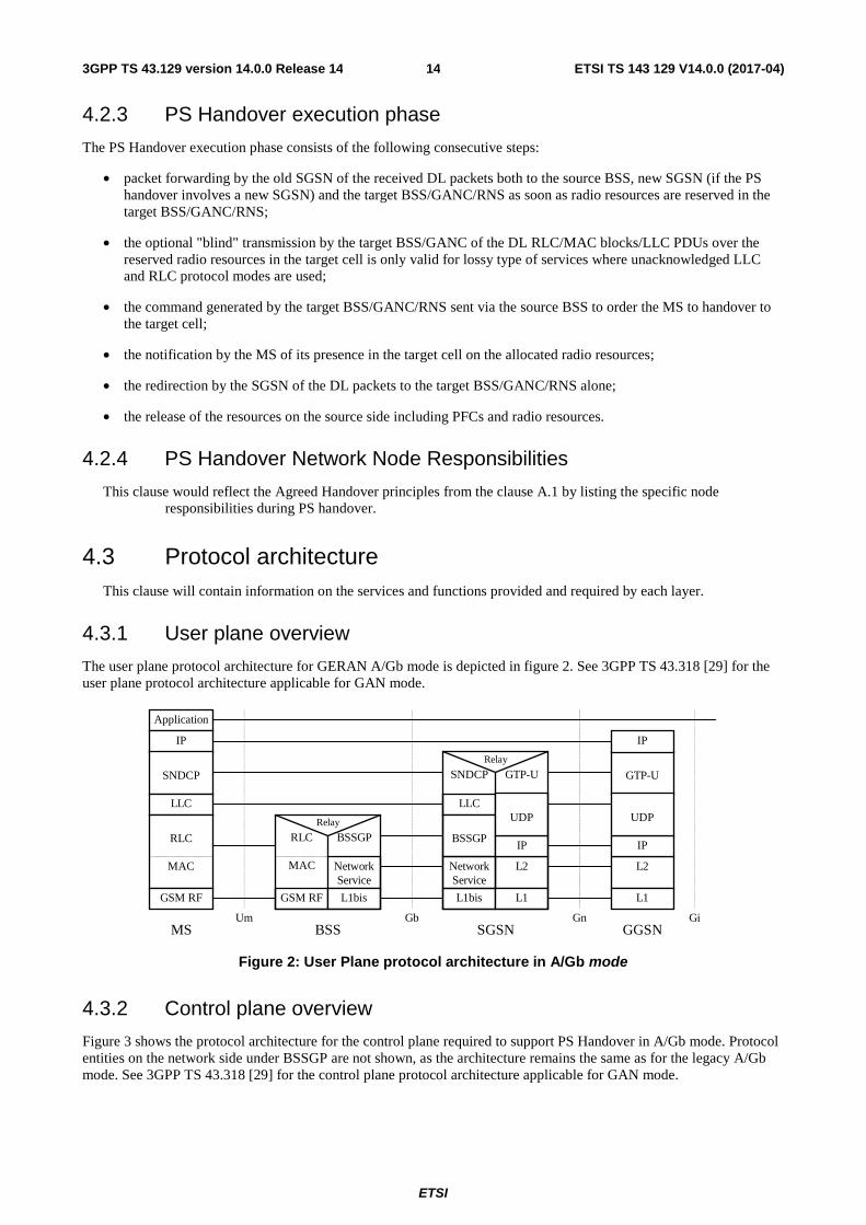
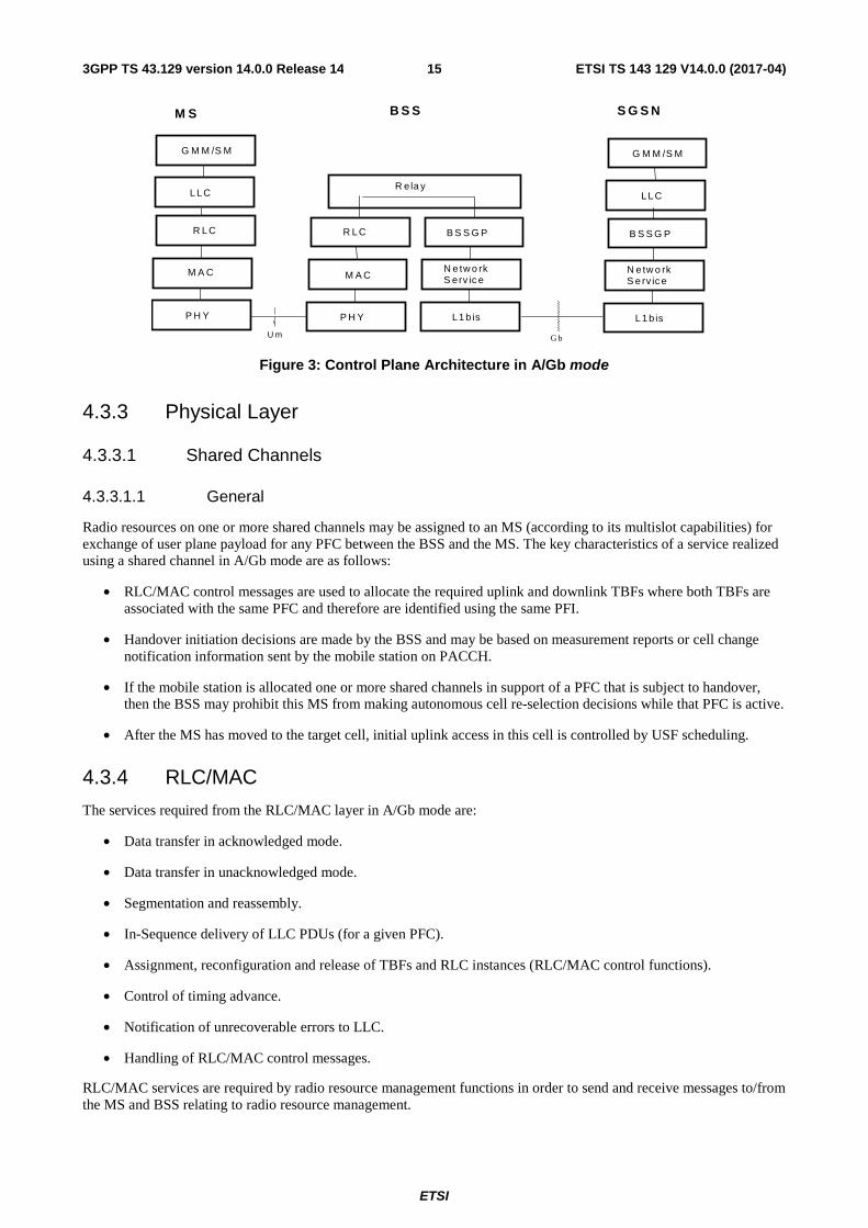
Figure 3 shows the protocol architecture for the control plane required to support PS Handover in A/Gb mode. Protocol entities on the network side under BSSGP are not shown, as the architecture remains the same as for the legacy A/Gb mode. See 3GPP TS 43.318 [29] for the control plane protocol architecture applicable for GAN mode.
Relay
NetworkService
GTP-U
Application
IP
SNDCP
LLC
RLC
MAC
GSM RF
SNDCP
LLC
BSSGP
L1bis
RLC
MAC
GSM RF
BSSGP
L1bis
Relay
L2
L1
IP
L2
L1
IP
GTP-U
IP
Um Gb Gn GiMS BSS SGSN GGSN
NetworkService
UDPUDP
ETSI
ETSI TS 143 129 V14.0.0 (2017-04)153GPP TS 43.129 version 14.0.0 Release 14
Figure 3: Control Plane Architecture in A/Gb mode
4.3.3 Physical Layer
4.3.3.1 Shared Channels
4.3.3.1.1 General
Radio resources on one or more shared channels may be assigned to an MS (according to its multislot capabilities) for exchange of user plane payload for any PFC between the BSS and the MS. The key characteristics of a service realized using a shared channel in A/Gb mode are as follows:
• RLC/MAC control messages are used to allocate the required uplink and downlink TBFs where both TBFs are associated with the same PFC and therefore are identified using the same PFI.
• Handover initiation decisions are made by the BSS and may be based on measurement reports or cell change notification information sent by the mobile station on PACCH.
• If the mobile station is allocated one or more shared channels in support of a PFC that is subject to handover, then the BSS may prohibit this MS from making autonomous cell re-selection decisions while that PFC is active.
• After the MS has moved to the target cell, initial uplink access in this cell is controlled by USF scheduling.
4.3.4 RLC/MAC
The services required from the RLC/MAC layer in A/Gb mode are:
• Data transfer in acknowledged mode.
• Data transfer in unacknowledged mode.
• Segmentation and reassembly.
• In-Sequence delivery of LLC PDUs (for a given PFC).
• Assignment, reconfiguration and release of TBFs and RLC instances (RLC/MAC control functions).
• Control of timing advance.
• Notification of unrecoverable errors to LLC.
• Handling of RLC/MAC control messages.
RLC/MAC services are required by radio resource management functions in order to send and receive messages to/from the MS and BSS relating to radio resource management.
B S S G P
U m
M S B S S
R ela y
S G S N
G b
L L C
G M M /S M
N e tw o rk S erv ic e
L1 b is
B S S G P
N e tw o rk S e rv ic e
L 1 b is
L L C
G M M /S M
R L C
M A C
P H Y
R L C
P H Y
M A C
ETSI
ETSI TS 143 129 V14.0.0 (2017-04)163GPP TS 43.129 version 14.0.0 Release 14
RLC/MAC supports the following radio resource management features that are required for PS handover:
• Establishment of a TBF on one or more physical channel(s) in a given direction, for a given PFC.
• Reconfiguration of the radio resources assigned to one or more TBFs in downlink and/or uplink within a cell.
• Release of TBFs and associated radio resources following the corresponding service deactivation.
• Release of all TBFs and associated radio resources in the source cell, as a result of handover to a target cell.
4.3.5 Radio Resource (RR)
This clause will contain information on any impacts on the RR protocol related to support of PS Handover.
4.3.6 BSSGP
BSSGP is expected to provide the signalling channel for PS Handover related signalling between the CN and the BSS/GANC.
The services required from the BSSGP layer can therefore be summarised as:
• Transmission and reception of PS Handover related messages (i.e. PFM messages) over the Gb interface.
• Routing of PS Handover related messages to the PFM entity.
• Handling of PS Handover related messages with the appropriate priority.
4.3.7 Overview of PS Handover Signalling Messages
The signalling messages used during PS handover are divided into four groups depending on the utilized interface:
• PS handover signalling messages on the Um interface are RLC/MAC signalling blocks.
• PS handover signalling messages on the Gb interface are BSSGP signalling messages sent by the PFM entity.
• PS handover signalling messages on the Gn interface are GTP signalling messages.
• PS handover signalling messages on the Up interface are GA-PSR signalling messages.
4.3.7.1 PS handover signalling messages on the Um interface
The signalling messages used on the Um interface are:
• PS Handover Command (BSS -> MS).
• Packet Control Acknowledgement (MS -> BSS).
• PS Handover Access - Access Bursts (MS -> BSS).
• Packet Physical Information (BSS->MS).
4.3.7.2 PS handover signalling messages on the Gb interface
The Gb interface signalling messages are new signalling messages carried by the BSSGP. These signalling messages are to be defined in 3GPP TS 48.018 [10].
The signalling messages used on the Gb interface are:
• PS Handover Required (BSS->CN):
- This message is sent from the BSS controlling the source cell to the SGSN to indicate that for a given MS which already has radio resource(s) assigned, a PS handover is required.
ETSI
ETSI TS 143 129 V14.0.0 (2017-04)173GPP TS 43.129 version 14.0.0 Release 14
• PS Handover Request (CN->BSS):
- This message is sent from the SGSN to the BSS controlling the target cell to request this BSS to reserve resources for the MS subject to PS Handover.
• PS Handover Request Acknowledge (BSS->CN):
- This message is sent from the BSS controlling the target cell to the SGSN to report the outcome of the resource allocation for the requested BSS PFCs. This message indicates to the SGSN the successful resource allocation and the failure for one or more requested BSS PFCs.
• PS Handover Request Negative Acknowledge (BSS -> CN):
- This message is sent from the BSS controlling the target cell to the SGSN to report the failure of the resource allocation for all the requested BSS PFCs.
• PS Handover Complete (BSS->CN):
- This message is sent from the BSS controlling the target cell to the SGSN to notify the SGSN that the MS has made a successful access on the target cell. If the PS Handover to UTRAN is supported by the MS and the BSS, it will also be used by the BSS to request the INTER RAT HANDOVER INFO from the SGSN.
• PS Handover Complete Ack (CN->BSS):
- This message is sent from the SGSN to the BSS controlling the target cell to provide the MS inter-RAT terminal capabilities (INTER RAT HANDOVER INFO) if those were requested by this BSS in the PS Handover Complete message.
• PS Handover Required Acknowledge (CN->BSS):
- This message is sent from the SGSN to the BSS controlling the source cell to indicate that the MS can switch to the target cell.
• PS Handover Cancel (BSS->CN):
- This message is sent from the BSS controlling the source cell to the SGSN to inform the SGSN to cancel an ongoing handover.
• PS Handover Required Negative Acknowledge (CN->BSS):
- This message is sent from the SGSN to the BSS controlling the source cell to inform unsuccessful resource allocation or other PS handover failure in the target cell.
4.3.7.3 PS handover signalling messages on the Gn interface
The Gn interface signalling messages are existing messages that will be used as described in 3GPP TS 29.060 [11].
The signalling messages used on the Gn interface between source SGSN and target SGSN are:
• Forward Relocation Request:
- The old SGSN shall send a Forward Relocation Request message to the new SGSN to convey necessary information to perform the PS handover procedure between new SGSN and Target BSS.
• Forward Relocation Response:
- The new SGSN shall send a Forward Relocation Response message to the old SGSN as a response to a previous Forward Relocation Request message.
• Forward Relocation Complete:
- The new SGSN shall send a Forward Relocation Complete message to the old SGSN to indicate that the PS Handover procedure has been successfully finished.
ETSI
ETSI TS 143 129 V14.0.0 (2017-04)183GPP TS 43.129 version 14.0.0 Release 14
• Forward Relocation Complete Acknowledge:
- The old SGSN sends a Forward Relocation Complete Acknowledge message to the new SGSN as a response to Forward Relocation Complete message.
• Relocation Cancel Request:
- The Relocation Cancel Request message is sent from the old SGSN to the new SGSN when the old SGSN is requested to cancel the PS Handover procedure by the source BSS by means of BSSGP message.
• Relocation Cancel Response:
- The Relocation Cancel Response message is sent from the new SGSN to the old SGSN when the PS handover procedure has been cancelled in the old SGSN. This message is used as the response to the Relocation Cancel Request message.
GTP messages need to be enhanced with additional IE to support PS Handover.
4.3.7.4 PS handover signalling messages on the Up interface
The signalling messages used on the Up interface (see 3GPP TS 44.318 [28]) are:
• GA-PSR HANDOVER COMMAND message (GANC � MS).
- This message is sent to trigger PS handover of an MS from a GAN cell to a GERAN A/Gb or UTRAN cell.
• GA-PSR UPLINK QUALITY INDICATION (GANC � MS)
- This message is sent to inform an MS of PS service related information as perceived by the GANC.
• GA-PSR HANDOVER INFORMATION message (MS � GANC)
- This message is sent by the MS to trigger the PS handover procedure in the GANC.
• GA-PSR ACTIVATE UTC REQ message (GANC � MS)
- This message is sent to allocate a GA-PSR Transport Channel to an MS.
• GA-PSR ACTIVATE UTC ACK message (MS � GANC)
- This message is sent to confirm the allocation of a GA-PSR Transport Channel to an MS.
• GA-PSR HANDOVER COMPLETE (MS � GANC)
- This message is sent to indicate the completion of PS handover to a GAN cell.
4.4 Identifiers The identifiers used in PS handover for GERAN A/Gb mode are the identities used by the MS to connect via GERAN through the Gb interface as well as through the Iu and S1 interface to the Core Network.
A large number of these identities for GERAN A/Gb mode will be utilized in the PS handover procedure in GERAN A/Gb mode in the same manner as specified currently. However in order to support PS handover procedure new identifiers will be defined as well.
In order to enable data transmission and to address the resources allocated by the target system during the PS Handover procedure (i.e. for the case where the target cell belongs to another RA), before the MS moves to the target cell a new P-TMSI will be allocated by the SGSN associated with the RA the target cell belongs to. The new P-TMSI is a temporary and unique identifier in the new RA and is used to assign a local TLLI for the target cell.
NOTE: Further in this TS the term "local TLLI" refers to the Local TLLI derived from new P-TMSI assigned by the new SGSN and utilized in the target cell, whereas the term "old TLLI" refers to the Local TLLI utilized in the source cell that is derived from the P-TMSI assigned by the old SGSN.
ETSI
ETSI TS 143 129 V14.0.0 (2017-04)193GPP TS 43.129 version 14.0.0 Release 14
In case of inter RAT PS Handover to/from UTRAN and inter-mode handover to/from GERAN Iu mode, existing UTRAN and GERAN Iu mode identifiers will be used.
In case of inter RAT PS Handover to/from E-UTRAN, identifiers defined for E-UTRAN will be used.
The existing as well as new identifiers utilized in PS handover procedure for GERAN A/Gb mode are listed in table 1.
Table 1: Identifiers utilized in PS handover in GERAN A/Gb mode
Identifier Specification reference
CI (Cell Identity) 3GPP TS 23.003 [12], 3GPP TS 25.401 [13], 3GPP TS 43.051 [14]
RAI (Routing Area Identity) 3GPP TS 23.003 [12] LAI (Location Area Identity) 3GPP TS 24.008 [15] IMSI (International Mobile Subscriber Identity) 3GPP TS 23.003 [12] P-TMSI (Packet Temporary Mobile Subscriber Identity) 3GPP TS 23.003 [12] TLLI (Temporary Logical Link Identity) 3GPP TS 23.003 [12] RNTI(Radio Network Temporary Identity) 3GPP TS 44.118 [16], 3GPP TS 25.401 [13] GRNTI (GERAN Radio Network Temporary Identity) 3GPP TS 25.401 [13] U-RNTI (UTRAN-RNTI) 3GPP TS 25.401 [13] TEID (Tunnel Endpoint Identifier) 3GPP TS 29.060 [11] NSAPI (Network Service Access Point Identifier) 3GPP TS 29.060 [11] TI (Transaction Identifier) 3GPP TS 24.007 [18] SAPI (Service Access Point Identifier) 3GPP TS 29.060 [11] PFI (Packet Flow Identifier) 3GPP TS 48.018 [10] BVCI (BSSGP Virtual Connection Identifier) 3GPP TS 48.018 [10] RAB Id (Radio Access Bearer Identifier) 3GPP TS 25.331 [17] RB Id (Radio Bearer Identifier) 3GPP TS 25.331 [17] and 3GPP TS36.331 [31] TFI (Temporary Flow Identity) 3GPP TS 44.060 [7] USF (Uplink State Flag) 3GPP TS 44.060 [7] Handover Reference 3GPP TS 44.018 [10] Cell RNTI (C-RNTI) 3GPP TS36.331 [31] eNB Identitiy 3GPP TS36.413 [34] MME Identity 3GPP TS23.003 [12] Tracking Area identity (TAI) 3GPP TS24.301 [33] EPS Bearer ID 3GPP TS24.007 [18]
4.4.1 NSAPI, PFI, RAB ID relation during inter-RAT, inter-mode UTRAN/GERAN Iu PS handover
During the inter-RAT and inter-mode PS handover to/from UTRAN/GERAN Iu there is a need to associate the MSs active PDP context with the BSS PFC and RABs in the respective SGSN(s).
As depicted in 3GPP TS 23.060 [19] NSAPI is a common identifier of the PDP context in all systems and as such it can be used by the MS to associate the active PDP contexts to the BSS PFC identified by the PFI and the RAB identified by the RAB Id during the inter-mode and inter-RAT PS handover. The MS has to associate the BSS PFC identified by the PFI utilized in a GERAN A/Gb mode cell or GAN mode cell with a RAB identified by RAB Id utilized in the UTRAN /GERAN Iu mode cell. This is done through the relation with the NSAPI, which is the common identifier in both systems. MS performs this association based on the identifiers received by the network.
The information received by the MS/UE depends on the RAT of the target cell:
• In case of the UTRAN/GERAN Iu mode target cell and GERAN A/Gb mode or GAN mode source cell, the MS shall receive the RAB Id and associate this with its existing PFIs based on the relation with NSAPI.
• In case of the GERAN A/Gb mode or GAN mode target cell, UTRAN/GERAN Iu mode source cell, the UE shall receive the PFI for each of the accepted NSAPIs and associate them with its existing RAB IDs based on the relation with NSAPI. An SGSN supporting PS Handover to GERAN A/Gb mode or GAN mode shall always assign a SAPI and it shall assign a valid PFI value if the UE has indicated the support of PS Handover procedures. The MS shall indicate in the MS network capability IE whether it supports "multiple TBFs". The SGSN may use this information when allocating the SAPI and PFI during PDP Context activation. During handover preparation the SAPI and PFI values shall be sent from the old SGSN to the new SGSN.
ETSI
ETSI TS 143 129 V14.0.0 (2017-04)203GPP TS 43.129 version 14.0.0 Release 14
• If the old SGSN did not assign a valid PFI value for one or more PDP Contexts, the new SGSN shall after successful completion of the RAU initiate explicit SM procedure to allocate a PFI value according to its policy for each of the PDP Contexts for which no PFI is currently allocated. If none of the PDP Contexts forwarded from the old SGSN has a valid PFI allocated the new SGSN shall consider this as a failure case and the request for PS handover shall be rejected..
4.4.2 NSAPI, PFI, EPS Bearer ID relation during inter-RAT GERAN / E-UTRAN PS handover
General principles for mapping between PDP contexts and EPS bearers are described in 3GPP TS23.060; the mapping of the QoS profiles is depicted in 3GPP TS 23.401. As specified in 3GPP TS 23.060 there is one to one mapping between a PDP Context and EPS bearer, and their respective identifiers NSAPI and EPS bearer ID. In E-UTRAN a radio bearer (RB) transports the packets of an EPS bearer between a UE and an eNodeB. As defined in 3GPP TS23.401, if a radio bearer exists, there is a one-to-one mapping between an EPS bearer and this radio bearer (RB).
The mobile station has to associate the BSS PFC identified by the PFI utilized in a GERAN A/Gb mode cell with a E-UTRAN radio bearer identified by RB Id. This is done by the mobile station through the relation with the NSAPI and EPS Bearer ID identifiers received by the network.
The MME supporting PS handover to/from GERAN performs similar functionality as the 3G SGSN such that it allocates a PFI for each active EPS bearer initiated in E-UTRAN: The new SGSN in GERAN then acts as follows:
• If for a given PDP Context the new SGSN does not receive a PFI from the MME then it will not proceed with the PS handover for this flow i.e. it will not request the target BSS to allocate TBF resources corresponding to that PDP Context.
• If none of the PDP Contexts forwarded from the MME has a valid PFI allocated the new SGSN will consider this as a failure case and the request for PS handover shall be rejected.
• All PDP contexts for which no resources are allocated by the new SGSN or for which the new SGSN cannot support the same SAPI and PFI (i.e. the corresponding NSAPIs are not addressed in the response message of the target SGSN) will however be maintained and the related SAPIs and PFIs will be kept. These PDP contexts may be modified or deactivated by the new SGSN via explicit SM procedures upon RAU procedure.
5 Signalling procedures
5.1 GERAN (A/Gb mode) � GERAN (A/Gb mode) handover
5.1.1 Intra Cell
Intra Cell PS Handover will be needed in cases when a new channel is selected in the same cell to be used by the MS. This is handled by the BSS internally and if there are no changes in the new channel there is no need for BSS to notify the SGSN about the change of channel.
BSS/SGSN signalling will be needed in case the new channel has limited resources and cannot support the same QoS, for the BSS PFC as the old channel.
For these purpose existing modification procedures on the Um and Gb interface are used, e.g. PACKET TIMESLOT RECONFIGURE (3GPP TS 44.060 [7]) on the air interface and MODIFY BSS PFC (3GPP TS 48.018 [10]) procedure on the Gb interface.
If the modification procedures fail BSS may cancel the intra cell PS handover procedure.
ETSI
ETSI TS 143 129 V14.0.0 (2017-04)213GPP TS 43.129 version 14.0.0 Release 14
5.1.2 Intra BSS
5.1.2.1 General
This clause is further split into two clauses. The first describes an intra-BSS handover procedure based largely on the inter-BSS handover procedure. The second section describes an optional optimised intra-BSS handover procedure. When the source and target cells are within the same BSS the handover can be either executed by the BSS itself (optimised handover) or by involving the SGSN in the preparation phase. In the latter case although handover is performed within one BSS the roles of source BSS and target BSS are the same as in Inter BSS Handover.
5.1.2.2 Intra BSS HO; Preparation phase
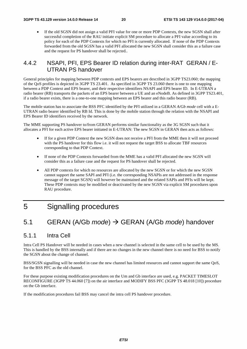
Figure 4: PS Handover Preparation Phase; Intra-BSS case (GERAN A/Gb mode � GERAN A/Gb mode)
1. The BSS decides to initiate a PS handover. At this point both uplink and downlink user data is transmitted via the following: TBFs between the MS and BSS, BSSGP PFCs tunnel(s) between the BSS and SGSN, GTP tunnel(s) between the SGSN and GGSN.
2. The BSS sends a PS Handover Required (Old TLLI, Cause, Source Cell Identifier, Target Cell Identifier, Source BSS to Target BSS Transparent Container (RN part), Active PFCs List) message to the SGSN.
3. The SGSN determines from the Target Cell Identifier the type of handover, i.e. intra-SGSN, inter-SGSN or inter-RAT/mode handover and whether the routing area has changed. In case of no change of routing area, the SGSN sends a PS Handover Request (TLLI, Cause, IMSI, Source Cell Identifier, Target Cell Identifier, PFCs To Be Set Up List, Source BSS to Target BSS Transparent Container (RN part)) message to the BSS. In case when the routing area changes the SGSN allocates a new P-TMSI for this MS and derives a local TLLI from this P-TMSI prior to the sending of the PS Handover Request message. The SGSN shall only request resources for PFCs that are included in the Active PFCs List.
NOTE: The BSS PFCs required to be set up are downloaded to the target BSS from the SGSN, i.e. all information required for PFC creation.
4. Based upon the ABQP for each PFC the BSS makes a decision about which PFCs to assign radio resources. The algorithm by which the BSS decides which PFCs that need resources is implementation specific. Due to resource limitations not all downloaded PFCs will necessarily receive resource allocation. The BSS allocates TBFs for each PFC that can be accommodated.
After allocating radio resources the target BSS shall prepare the Target BSS to Source BSS Transparent Container for the set up BSS PFCs.
5. The BSS shall send the PS Handover Request Acknowledge (TLLI, List of Set Up PFCs, Target BSS to Source BSS Transparent Container (PS Handover Command with RN part)) message to the SGSN. Upon sending the PS Handover Request Acknowledge message the BSS shall be prepared to receive downlink LLC PDUs directed to the new cell and associated with the accepted PFCs.
MS SGSN BSS
3. PS Handover Request
2. PS handover Required
5. PS Handover Request Acknowledge
1. Decision to perform A/Gb PS Handover
4. BSS reserves radio resources and creates the Target BSS to Source BSS Transparent Container
ETSI
ETSI TS 143 129 V14.0.0 (2017-04)223GPP TS 43.129 version 14.0.0 Release 14
When the SGSN receives the PS Handover Request Acknowledge message and it decides to proceed with the handover, the preparation phase is finished and the execution phase will follow.
5.1.2.3 Intra BSS HO; Execution phase
MS SGSN BSS GGSN
1. GTP Packets to SGSN
2. PS Handover Required Acknowledge
4. PS Handover Access
5. Packet Physical Information
7. PS Handover Complete
6. RA/Cell Update
3. PS Handover Command
Sending of uplink data possible
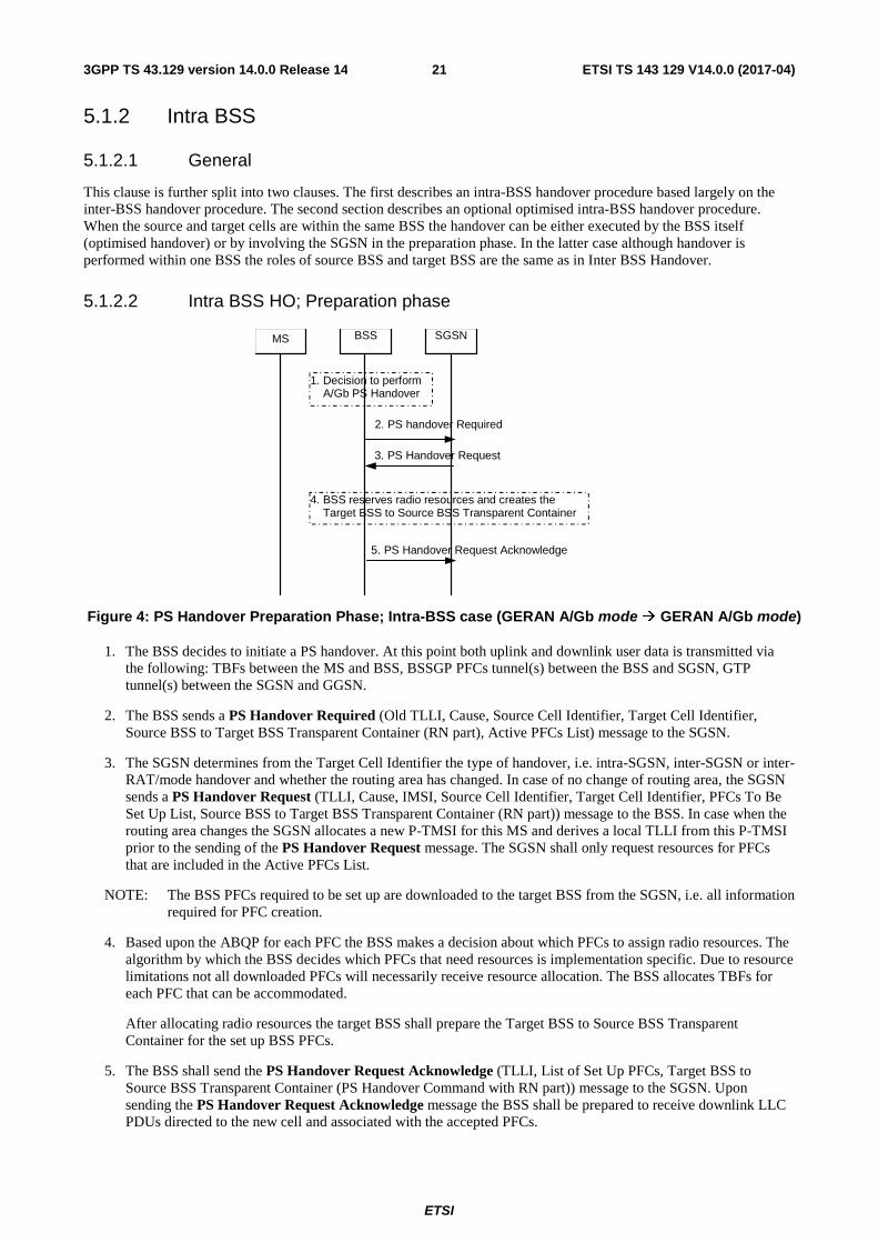
Figure 5: PS Handover Execution Phase; Intra-BSS case (GERAN A/Gb mode � GERAN A/Gb mode)
1. The SGSN continues to receive GTP packets from the GGSN (via GTP) and forwards the associated PDU payload to the MS via the BSS.
When receiving the PS Handover Request Acknowledge message the SGSN may, based on QoS, start duplication of LLC PDUs and forward those to the new cell in the BSS. If the SGSN forwards downlink packets to the new cell in the BSS, the BSS may start blind transmission of downlink user data towards the MS over the allocated radio channels.
2. The SGSN continues the PS Handover by sending a PS Handover Required Acknowledge (Old TLLI, List of Set Up PFCs, Target BSS to Source BSS Transparent Container (PS Handover Command with RN part)) message to the BSS.
Before sending the PS Handover Required Acknowledge message, the SGSN, based on QoS, may suspend downlink data transfer for any PDP contexts.
Before sending the PS Handover Command message to the MS the BSS, based on QoS, may try to empty the downlink BSS buffer for any BSS PFCs.
NOTE 1: Only PFI(s) for PFCs accepted by the target cell are included in the message.
3. The BSS sends the PS Handover Command (RN part) message to the MS by interrupting the transmission of LLC PDUs on any of the downlink TBFs. Following the transmission of this signalling message the BSS may resume LLC PDU transmission until it either has no more LLC PDUs to send or the PFC is released. Upon reception of the PS Handover Command the MS is not required to continue data reception in the source cell. The MS shall suspend the uplink transmission of user plane data. MS management of uplink N-PDUs following the reception of the PS Handover Command message is as follows:
• All uplink packets associated with a PFC receiving handover treatment that have not yet been fully transmitted might be buffered depending on the QoS class.
• Subsequent uplink packets that become available for transmission following the reception of the PS Handover Command message might also be buffered depending on the QoS class.
• The MS may discard uplink packets during the link interruption to preserve the real-time properties.
4. The MS tunes to the radio channel and the timeslot allocated in the target cell by the BSS and may send the PS Handover Access (Handover Reference) message in the form of four handover access bursts to the BSS on the
ETSI
ETSI TS 143 129 V14.0.0 (2017-04)233GPP TS 43.129 version 14.0.0 Release 14
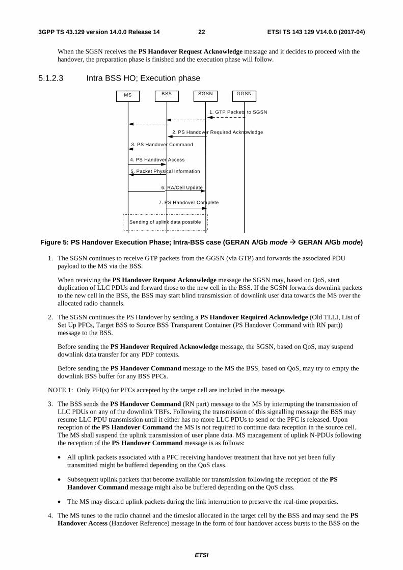
allocated channel. The PS Handover Command message indicates whether or not the MS shall send PS Handover Access messages.
5. The BSS sends a Packet Physical information message to the MS containing update of the timing advance for the MS to synchronize.
NOTE 2: In the case of pre-synchronised handover the MS may receive the timing advance information to use in uplink in the target cell in the PS Handover Command message (if no timing advance information is included, the mobile station uses a default timing advance in the target cell). In a pre-synchronised or synchronised handover, the Packet Physical information message is not sent in the target cell.
6. The MS sends uplink LLC PDUs, e.g. a Routing Area Update Request message or uplink user data packets to the SGSN immediately after receiving the Packet Physical Information message or, in a synchronised or pre-synchronised handover, immediately if the PS Handover Access message is not required to be sent (see Section 6.2).
The MS shall resume the user data transfer only for those NSAPIs for which radio resources are allocated in the target cell. For NSAPIs using LLC ADM for which radio resources were not allocated in the target cell the MS may request radio resources using the legacy procedures.
7. Upon reception of the first correct RLC/MAC block (sent in normal burst format) from the MS the BSS sends a PS Handover Complete (TLLI, IMSI) message to inform the SGSN that the MS has arrived in the target cell. After the reception of the PS Handover Complete message the SGSN shall initiate the BSS PFC procedures to delete the BSS PFC in the BSS controlling the source cell and shall be prepared to receive data from the new cell. The source BSS initiates the release of the radio resources in the source cell after receiving the DELETE-BSS-PFC PDU from the SGSN.
If Routing Area Update occurs after completion of the execution phase, then the CAMEL procedure calls shall be performed according to 3GPP TS 23.060.
5.1.2.4 Intra BSS Handover - Optimised
This clause describes the optimised intra-BSS PS handover procedures applicable for the case where the source and target cells are associated with the same Network Service Entity (NSE) and the same Routing Area (RA). The optimisation involves the BSS providing the data forwarding function and does not require any explicit signalling with the SGSN except the sending of PS Handover Complete at the end of PS Handover. Support for this procedure is optional for the BSS.
Supporting this procedure requires that the BSS be able to determine whether or not it manages PS resources for the target cell, whether or not the target cell is associated with the same NSE, that it can internally forward LLC PDUs from the source to the target cell and whether or not both cells are part of the same RA (i.e. the SGSN is not required to make this determination and relay this information). If the BSS cannot make these determinations it shall use the non-optimised intra-BSS PS handover procedures described in clauses 5.1.2.2 and 5.1.2.3.
ETSI
ETSI TS 143 129 V14.0.0 (2017-04)243GPP TS 43.129 version 14.0.0 Release 14
7. PS Handover Complete
MS BSS SGSN
2. BSS determines that it manages target cell and that it is part of same NSE and RA as the source cell
1. BSS decides to initiate A/Gb mode PS handover
4. PS Handover Access
3. PS Handover Command
9. DL LLC PDU (new BVCI)
8. Packet Uplink Ack/Nack
5. Packet Physical Information
6. UL RLC/MAC data andover Access
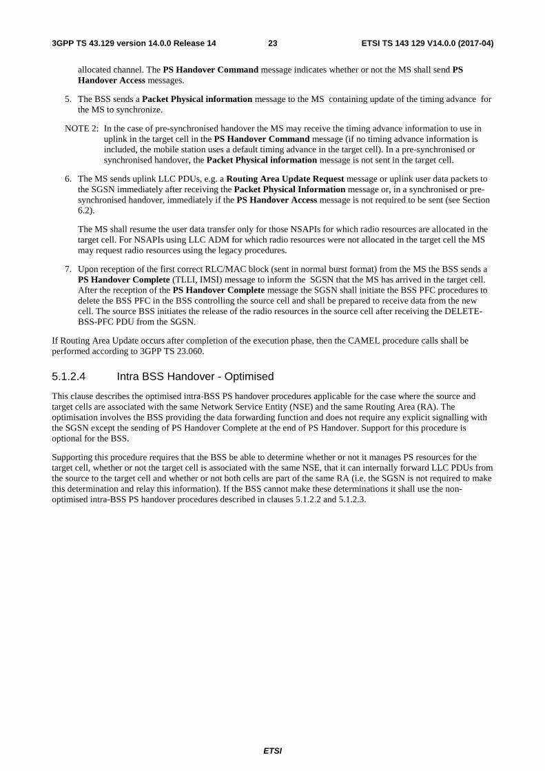
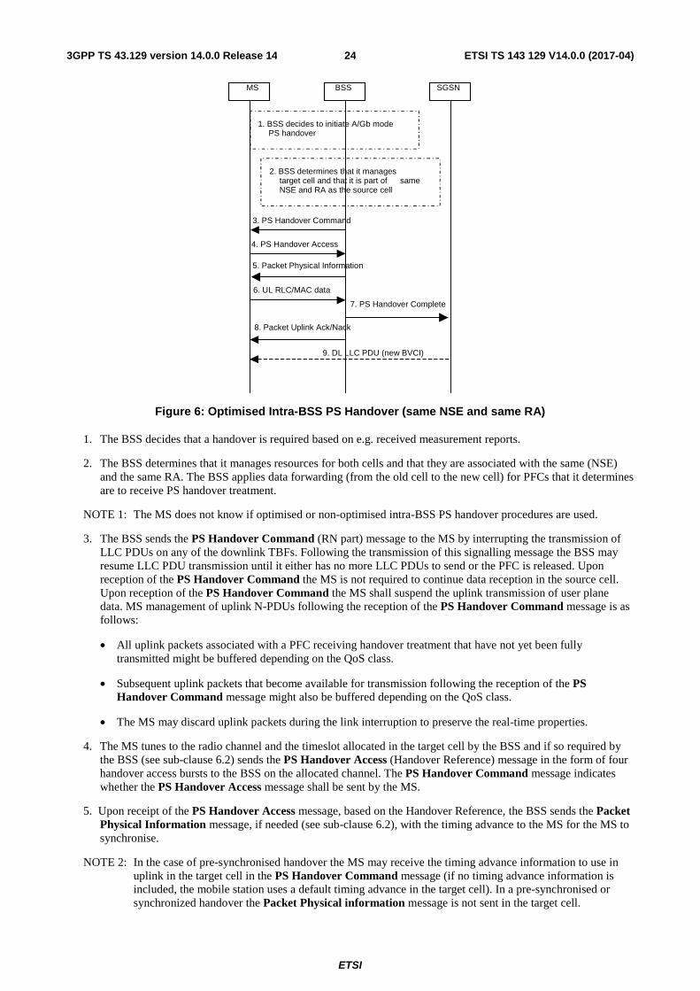
Figure 6: Optimised Intra-BSS PS Handover (same NSE and same RA)
1. The BSS decides that a handover is required based on e.g. received measurement reports.
2. The BSS determines that it manages resources for both cells and that they are associated with the same (NSE) and the same RA. The BSS applies data forwarding (from the old cell to the new cell) for PFCs that it determines are to receive PS handover treatment.
NOTE 1: The MS does not know if optimised or non-optimised intra-BSS PS handover procedures are used.
3. The BSS sends the PS Handover Command (RN part) message to the MS by interrupting the transmission of LLC PDUs on any of the downlink TBFs. Following the transmission of this signalling message the BSS may resume LLC PDU transmission until it either has no more LLC PDUs to send or the PFC is released. Upon reception of the PS Handover Command the MS is not required to continue data reception in the source cell. Upon reception of the PS Handover Command the MS shall suspend the uplink transmission of user plane data. MS management of uplink N-PDUs following the reception of the PS Handover Command message is as follows:
• All uplink packets associated with a PFC receiving handover treatment that have not yet been fully transmitted might be buffered depending on the QoS class.
• Subsequent uplink packets that become available for transmission following the reception of the PS Handover Command message might also be buffered depending on the QoS class.
• The MS may discard uplink packets during the link interruption to preserve the real-time properties.
4. The MS tunes to the radio channel and the timeslot allocated in the target cell by the BSS and if so required by the BSS (see sub-clause 6.2) sends the PS Handover Access (Handover Reference) message in the form of four handover access bursts to the BSS on the allocated channel. The PS Handover Command message indicates whether the PS Handover Access message shall be sent by the MS.
5. Upon receipt of the PS Handover Access message, based on the Handover Reference, the BSS sends the Packet Physical Information message, if needed (see sub-clause 6.2), with the timing advance to the MS for the MS to synchronise.
NOTE 2: In the case of pre-synchronised handover the MS may receive the timing advance information to use in uplink in the target cell in the PS Handover Command message (if no timing advance information is included, the mobile station uses a default timing advance in the target cell). In a pre-synchronised or synchronized handover the Packet Physical information message is not sent in the target cell.
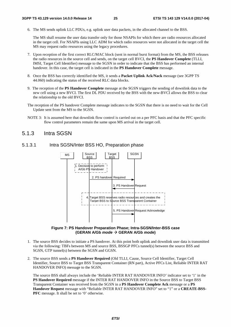
ETSI
ETSI TS 143 129 V14.0.0 (2017-04)253GPP TS 43.129 version 14.0.0 Release 14
6. The MS sends uplink LLC PDUs, e.g. uplink user data packets, in the allocated channel to the BSS.
The MS shall resume the user data transfer only for those NSAPIs for which there are radio resources allocated in the target cell. For NSAPIs using LLC ADM for which radio resources were not allocated in the target cell the MS may request radio resources using the legacy procedures.
7. Upon reception of the first correct RLC/MAC block (sent in normal burst format) from the MS, the BSS releases the radio resources in the source cell and sends, on the target cell BVCI, the PS Handover Complete (TLLI, IMSI, Target Cell Identifier) message to the SGSN in order to indicate that the BSS has performed an internal handover. In this case, the target cell is indicated in the PS Handover Complete message.
8. Once the BSS has correctly identified the MS, it sends a Packet Uplink Ack/Nack message (see 3GPP TS 44.060) indicating the status of the received RLC data blocks.
9. The reception of the PS Handover Complete message at the SGSN triggers the sending of downlink data to the new cell using a new BVCI. The first DL PDU received by the BSS with the new-BVCI allows the BSS to clear the relationship to the old BVCI.
The reception of the PS handover Complete message indicates to the SGSN that there is no need to wait for the Cell Update sent from the MS to the SGSN.
NOTE 3: It is assumed here that downlink flow control is carried out on a per PFC basis and that the PFC specific flow control parameters remain the same upon MS arrival in the target cell.
5.1.3 Intra SGSN
5.1.3.1 Intra SGSN/Inter BSS HO, Preparation phase
Figure 7: PS Handover Preparation Phase; Intra-SGSN/Inter-BSS case (GERAN A/Gb mode � GERAN A/Gb mode)
1. The source BSS decides to initiate a PS handover. At this point both uplink and downlink user data is transmitted via the following: TBFs between MS and source BSS, BSSGP PFCs tunnel(s) between the source BSS and SGSN, GTP tunnel(s) between the SGSN and GGSN.
2. The source BSS sends a PS Handover Required (Old TLLI, Cause, Source Cell Identifier, Target Cell Identifier, Source BSS to Target BSS Transparent Container (RN part), Active PFCs List, Reliable INTER RAT HANDOVER INFO) message to the SGSN.
The source BSS shall always include the ‘Reliable INTER RAT HANDOVER INFO’ indicator set to ‘1’ in the PS Handover Required message if the INTER RAT HANDOVER INFO in the Source BSS to Target BSS Transparent Container was received from the SGSN in a PS Handover Complete Ack message or a PS Handover Request message with “Reliable INTER RAT HANDOVER INFO” set to “1” or a CREATE-BSS-PFC message. It shall be set to ‘0’ otherwise.
MS Target BSS
Source BSS
SGSN
3. PS Handover Request
2. PS handover Required
5. PS Handover Request Acknowledge
1. Decision to perform A/Gb PS Handover
4. Target BSS reserves radio resources and creates the Target BSS to Source BSS Transparent Container
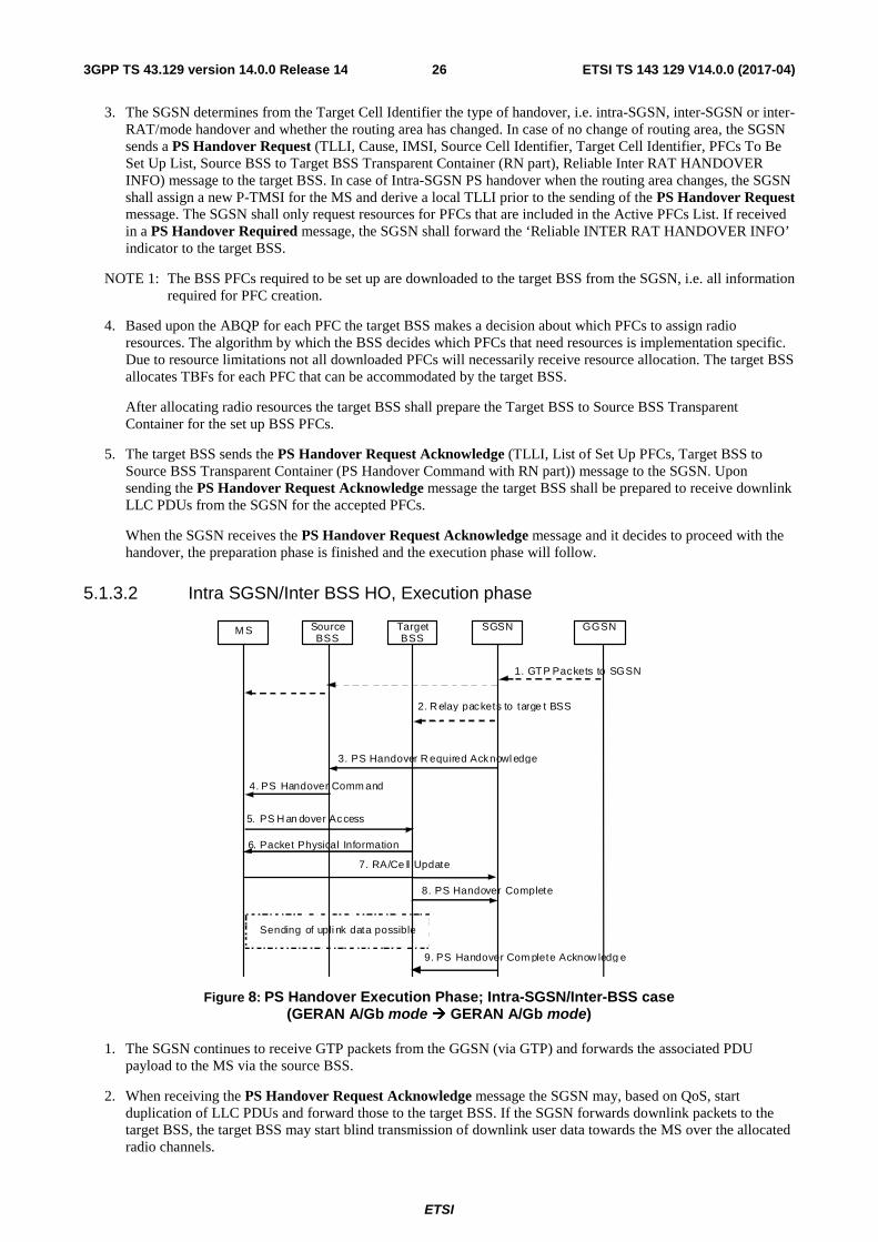
ETSI
ETSI TS 143 129 V14.0.0 (2017-04)263GPP TS 43.129 version 14.0.0 Release 14
3. The SGSN determines from the Target Cell Identifier the type of handover, i.e. intra-SGSN, inter-SGSN or inter-RAT/mode handover and whether the routing area has changed. In case of no change of routing area, the SGSN sends a PS Handover Request (TLLI, Cause, IMSI, Source Cell Identifier, Target Cell Identifier, PFCs To Be Set Up List, Source BSS to Target BSS Transparent Container (RN part), Reliable Inter RAT HANDOVER INFO) message to the target BSS. In case of Intra-SGSN PS handover when the routing area changes, the SGSN shall assign a new P-TMSI for the MS and derive a local TLLI prior to the sending of the PS Handover Request message. The SGSN shall only request resources for PFCs that are included in the Active PFCs List. If received in a PS Handover Required message, the SGSN shall forward the ‘Reliable INTER RAT HANDOVER INFO’ indicator to the target BSS.
NOTE 1: The BSS PFCs required to be set up are downloaded to the target BSS from the SGSN, i.e. all information required for PFC creation.
4. Based upon the ABQP for each PFC the target BSS makes a decision about which PFCs to assign radio resources. The algorithm by which the BSS decides which PFCs that need resources is implementation specific. Due to resource limitations not all downloaded PFCs will necessarily receive resource allocation. The target BSS allocates TBFs for each PFC that can be accommodated by the target BSS.
After allocating radio resources the target BSS shall prepare the Target BSS to Source BSS Transparent Container for the set up BSS PFCs.
5. The target BSS sends the PS Handover Request Acknowledge (TLLI, List of Set Up PFCs, Target BSS to Source BSS Transparent Container (PS Handover Command with RN part)) message to the SGSN. Upon sending the PS Handover Request Acknowledge message the target BSS shall be prepared to receive downlink LLC PDUs from the SGSN for the accepted PFCs.
When the SGSN receives the PS Handover Request Acknowledge message and it decides to proceed with the handover, the preparation phase is finished and the execution phase will follow.
5.1.3.2 Intra SGSN/Inter BSS HO, Execution phase
Figure 8: PS Handover Execution Phase; Intra-SGSN/Inter-BSS case (GERAN A/Gb mode � GERAN A/Gb mode)
1. The SGSN continues to receive GTP packets from the GGSN (via GTP) and forwards the associated PDU payload to the MS via the source BSS.
2. When receiving the PS Handover Request Acknowledge message the SGSN may, based on QoS, start duplication of LLC PDUs and forward those to the target BSS. If the SGSN forwards downlink packets to the target BSS, the target BSS may start blind transmission of downlink user data towards the MS over the allocated radio channels.
M S Target BSS
Source BSS
SGSN GGSN
1. GTP Packets to SGSN
3. PS Handover R equired Acknowl edge
5. PS H an dover Access
6. Packet Physical Information
8. PS Handover Complete
7. RA/Ce ll Update
4. PS Handover Comm and
2. R elay packets to targe t BSS
Sending of upli nk data possible
9. PS Handover Com plete Acknow ledg e
ETSI
ETSI TS 143 129 V14.0.0 (2017-04)273GPP TS 43.129 version 14.0.0 Release 14
3. The SGSN continues the PS Handover by sending a PS Handover Required Acknowledge (Old TLLI, List of Set Up PFCs, Target BSS to Source BSS Transparent Container (PS Handover Command with RN part)) message to the source BSS.
Before sending the PS Handover Required Acknowledge message, the SGSN, based on QoS, may suspend downlink data transfer for any PDP contexts.
Before sending the PS Handover Command message to the MS the source BSS, based on QoS, may try to empty the downlink BSS buffer for any BSS PFCs.
NOTE 1: Only PFI(s) for PFCs accepted by the target cell are included in the message.
4. The source BSS sends the PS Handover Command (RN part) message to the MS by interrupting the transmission of LLC PDUs on any of the downlink TBFs. Following the transmission of this signalling message the source BSS may resume LLC PDU transmission until it either has no more LLC PDUs to send or the PFC is released. Upon reception of the PS Handover Command message the MS is not required to continue data reception in the source cell. Upon reception of the PS Handover Command message the MS shall suspend the uplink transmission of user plane data. MS management of uplink N-PDUs following the reception of the PS Handover Command message is as follows:
• All uplink packets associated with a PFC receiving handover treatment that have not yet been fully transmitted might be buffered depending on the QoS class.
• Subsequent uplink packets that become available for transmission following the reception of the PS Handover Command message might also be buffered depending on the QoS class.
• The MS may discard uplink packets during the link interruption to preserve the real-time properties.
5. The MS tunes to the radio channel and the timeslot allocated in the target cell by the BSS and may send the PS Handover Access (Handover Reference) message in the form of four handover access bursts to the BSS on the allocated channel. The PS Handover Command message indicates whether or not the MS shall send PS Handover Access messages.
6. The target BSS sends a Packet Physical information message to the MS containing the timing advance for the MS to synchronise.
NOTE 2: In the case of pre-synchronised handover the MS may receive the timing advance information to use in uplink in the target cell in the PS Handover Command message (if no timing advance information is included, the mobile station uses a default timing advance in the target cell). In a pre-synchronised or synchronized handover, the Packet Physical Information message is not sent in the target cell.
7. The MS sends uplink LLC PDUs, e.g. a Routing Area Update Request message or uplink user data packets to the SGSN immediately after receiving the Packet Physical Information message or, in a synchronised or pre-synchronised handover, immediately if the PS Handover Access message is not required to be sent (see Section 6.2).
The MS shall resume the user data transfer only for those NSAPIs for which there are radio resources allocated in the target cell. For NSAPIs using LLC ADM for which radio resources were not allocated in the target cell the MS may request for radio resources using the legacy procedures.
8. Upon reception of the first correct RLC/MAC block (sent in normal burst format) from the MS the target BSS sends a PS Handover Complete (TLLI, IMSI, Request for Inter RAT Handover Info) message to inform the SGSN that the MS has arrived in the target cell. After the reception of the PS Handover Complete message the SGSN shall initiate the BSS PFC procedures to delete the BSS PFC in the BSS controlling the source cell and shall be prepared to receive data from the new cell. The source BSS initiates the release of the radio resources in the source cell after receiving the DELETE-BSS-PFC PDU from the SGSN. The target BSS that supports inter-RAT PS handover to UTRAN shall request the INTER RAT HANDOVER INFO from the SGSN if the ‘Reliable INTER RAT HANDOVER INFO’ is missing or set to ‘0’ in the PS Handover Request message or if it has not received the INTER RAT HANDOVER INFO as part of the Source BSS to Target BSS transparent container.
9. Upon reception of the PS Handover Complete message with the “Request for INTER RAT HANDOVER INFO” set to “1” for UTRAN, the SGSN shall send PS Handover Complete Acknowledge (TLLI, Inter RAT Handover Info) to the target BSS.
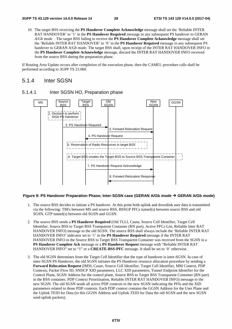
ETSI
ETSI TS 143 129 V14.0.0 (2017-04)283GPP TS 43.129 version 14.0.0 Release 14
10. The target BSS receiving the PS Handover Complete Acknowledge message shall set the ‘Reliable INTER RAT HANDOVER’ to ‘1’ in the PS Handover Required message in any subsequent PS handover to GERAN A/Gb mode . The target BSS failing to receive the PS Handover Complete Acknowledge message shall set the ‘Reliable INTER RAT HANDOVER’ to ‘0’ in the PS Handover Required message in any subsequent PS handover to GERAN A/Gb mode. The target BSS shall, upon receipt of the INTER RAT HANDOVER INFO in the PS Handover Complete Acknowledge message, discard the INTER RAT HANDOVER INFO received from the source BSS during the preparation phase.
If Routing Area Update occurs after completion of the execution phase, then the CAMEL procedure calls shall be performed according to 3GPP TS 23.060.
5.1.4 Inter SGSN
5.1.4.1 Inter SGSN HO, Preparation phase
MS Target BSS
Source BSS
Old SGSN
New SGSN
GGSN
3. Forward Relocation Request
4. PS Handover Request
2. PS Handover Required
8. Forward Relocation Response
7. PS Handover Request Acknowledge
1. Decision to perform A/Gb PS Handover
5. Reservation of Radio Resources in target BSS
6. Target BSS creates the Target BSS to Source BSS Transparent Container
Figure 9: PS Handover Preparation Phase; Inter-SGSN case (GERAN A/Gb mode � GERAN A/Gb mode)
1. The source BSS decides to initiate a PS handover. At this point both uplink and downlink user data is transmitted via the following: TBFs between MS and source BSS, BSSGP PFCs tunnel(s) between source BSS and old SGSN, GTP tunnel(s) between old SGSN and GGSN.
2. The source BSS sends a PS Handover Required (Old TLLI, Cause, Source Cell Identifier, Target Cell Identifier, Source BSS to Target BSS Transparent Container (RN part), Active PFCs List, Reliable Inter RAT HANDOVER INFO) message to the old SGSN. The source BSS shall always include the ‘Reliable INTER RAT HANDOVER INFO’ indicator set to ‘1’ in the PS Handover Required message if the INTER RAT HANDOVER INFO in the Source BSS to Target BSS Transparent Container was received from the SGSN in a PS Handover Complete Ack message or a PS Handover Request message with “Reliable INTER RAT HANDOVER INFO” set to “1” or a CREATE-BSS-PFC message. It shall be set to ‘0’ otherwise.
3. The old SGSN determines from the Target Cell Identifier that the type of handover is inter-SGSN. In case of inter-SGSN PS Handover, the old SGSN initiates the PS Handover resource allocation procedure by sending a Forward Relocation Request (IMSI, Cause, Source Cell Identifier, Target Cell Identifier, MM Context, PDP Contexts, Packet Flow ID, SNDCP XID parameters, LLC XID parameters, Tunnel Endpoint Identifier for the Control Plane, SGSN Address for the control plane, Source BSS to Target BSS Transparent Container (RN part) in the BSS container, PDP Context Prioritisation, Reliable INTER RAT HANDOVER INFO) message to the new SGSN. The old SGSN sends all active PDP contexts to the new SGSN indicating the PFIs and the XID parameters related to those PDP contexts. Each PDP context contains the GGSN Address for the User Plane and the Uplink TEID for Data (to this GGSN Address and Uplink TEID for Data the old SGSN and the new SGSN send uplink packets).
ETSI
ETSI TS 143 129 V14.0.0 (2017-04)293GPP TS 43.129 version 14.0.0 Release 14
The MM context contains security related information, e.g. used ciphering algorithm and ciphering key as decribed in 3GPP TS 29.060 [11]. The relation between GSM and UMTS security parameters is defined in 3GPP TS 33.102 [27].
The Ciphering key used by the old SGSN is reused by the new SGSN until a new authentication procedure is performed (see clause 5.1.4.2, bullet 13).
If the new SGSN does not support the indicated ciphering algorithm, the new SGSN has to select a new ciphering algorithm. This new algorithm will be sent transparently from the new SGSN to the MS. The IOV-UI parameter generated in the new SGSN and used as input to the ciphering procedure will also be transferred transparently from the new SGSN to the MS.
When the new SGSN receives the Forward Relocation Request message it extracts from the PDP Contexts the associated NSAPIs, SAPIs and PFIs to be used in the new SGSN. In case when the new SGSN does not support the same SAPI and PFI indicated by the old SGSN for a certain NSAPI, the new SGSN shall continue the PS handover procedure only for those NSAPIs for which it can support the same PFI and SAPI as the old SGSN and for which it can allocate resources. All PDP contexts for which no resources are allocated by the new SGSN or for which it cannot support the same SAPI and PFI (i.e. the corresponding NSAPIs are not addressed in the Forward Relocation Response message of the target SGSN), are maintained in the new SGSN and the related SAPIs and PFIs are kept. When this occurs the packet data transfer corresponding to PDP Contexts for which new SAPI and PFI values are needed are suspended. These PDP contexts may be modified or deactivated by the new SGSN via explicit SM procedures upon the completion of the routing area update (RAU) procedure. When the required PDP, MM, SNDCP and LLC contexts are established and the mapping between NSAPI, SAPI and PFI for each of these PDP Contexts is established, the corresponding packet data transfer can continue.
If for a given PDP Context the new SGSN does not receive a PFI from the old SGSN, it shall not request the target BSS to allocate TBF resources corresponding to that PDP Context.
If none of the PDP Contexts forwarded from the old SGSN has a valid PFI allocated the new SGSN shall consider this as a failure case and the request for PS handover shall be rejected.
The old SGSN shall indicate the current XID parameter settings (i.e. those used at the old SGSN) to the new SGSN. If the new SGSN can accept all XID parameters as indicated by the old SGSN, the new SGSN shall create a NAS container for PS HO indicating 'Reset to the old XID parameters'.
NOTE 1: 'Reset to the old XID parameters' means that the LLC and SNDCP layer are reset, except for the LLC XID parameters and SNDCP XID parameters which are re-initialized to the latest negotiated values, and the negotiated compression entities which are re-initialized.
NOTE 2: void
Otherwise the new SGSN shall create a NAS container for PS HO indicating Reset (i.e. reset to default parameters).
If received in a PS Handover Required message, the old SGSN shall forward the ‘Reliable INTER RAT HANDOVER INFO’ indicator to the new SGSN in the Forward Relocation Request message.
4. The new SGSN sends a PS Handover Request (Local TLLI, Cause, IMSI, Source Cell Identifier, Target Cell Identifier, Source BSS to Target BSS Transparent Container (RN part), PFCs To Be Set Up List, NAS container for PS HO, Reliable Inter RAT HANDOVER INFO) message to the target BSS. The new SGSN shall not request resources for PFCs associated with PDP contexts with a maximum bit rate for uplink and downlink of 0 kbit/s or for which the Activity Status Indicator within the PDP Context indicates that no active PFC exists on the source side.
NOTE 3: The BSS PFCs required to be set up are downloaded to the target BSS from the new SGSN, i.e. all information required for PFC creation.
5. Based upon the ABQP for each PFC the target BSS makes a decision about which PFCs to assign radio resources. The algorithm by which the BSS decides which PFCs that need resources is implementation specific. Due to resource limitations not all downloaded PFCs will necessarily receive resource allocation. The target BSS allocates TBFs for each PFC that can be accommodated by the target BSS.
6. The target BSS shall prepare the Target BSS to Source BSS Transparent Container which contains a PS Handover Command including the CN part (NAS container for PS HO) and the RN part (PS Handover Radio Resources).
ETSI
ETSI TS 143 129 V14.0.0 (2017-04)303GPP TS 43.129 version 14.0.0 Release 14
7. The target BSS shall send the PS Handover Request Acknowledge (Local TLLI, List of Set Up PFCs, Target BSS to Source BSS Transparent Container) message to the new SGSN. Upon sending the PS Handover Request Acknowledge message the target BSS shall be prepared to receive downlink LLC PDUs from the new SGSN for the accepted PFCs.
8. When the new SGSN receives the PS Handover Request Acknowledge message the Forward Relocation Response (Cause, List of Set Up PFCs, Target BSS to Source BSS Transparent Container in the BSS Container, Tunnel Endpoint Identifier Control Plane, SGSN Address for the control plane, Tunnel Endpoint Identifier Data II) message is sent from the new SGSN to the old SGSN. This message indicates that the new SGSN is ready to receive packets forwarded from the old SGSN. If the target BSS or the new SGSN failed to allocate resources this shall be indicated in the message. The Tunnel Endpoint Identifier Data II, one information for each PDP context, contains the tunnel endpoint of the new SGSN and the IP address of the new SGSN for data forwarding from the old to the new SGSN.
The new SGSN activates the allocated LLC/SNDCP engines as specified in 3GPP TS 44.064 [21] for an SGSN originated Reset or 'Reset to the old XID parameters'.
When the old SGSN receives the Forward Relocation Response message and it decides to proceed with the handover, the preparation phase is finished and the execution phase will follow.
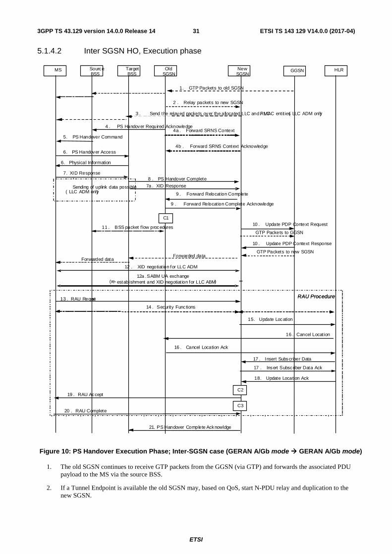
ETSI
ETSI TS 143 129 V14.0.0 (2017-04)313GPP TS 43.129 version 14.0.0 Release 14
5.1.4.2 Inter SGSN HO, Execution phase
Figure 10: PS Handover Execution Phase; Inter-SGSN case (GERAN A/Gb mode � GERAN A/Gb mode)
1. The old SGSN continues to receive GTP packets from the GGSN (via GTP) and forwards the associated PDU payload to the MS via the source BSS.
2. If a Tunnel Endpoint is available the old SGSN may, based on QoS, start N-PDU relay and duplication to the new SGSN.
MS TargetBSS
Source BSS
OldSGSN
NewSGSN
GGSN
5. PS Handover Command
2 . Relay packets to new SGSN
3 . Send the relayed packets over the allocated LLC and RLC/ MAC entit ies ( LLC ADM only)
1. GTP Packets to old SGSN
4 . PS Handover Required Acknowledge
10 . Update PDP Context Request
10 . Update PDP Context Response
6. PS Handover Access
HLR
GTP Packets to new SGSN
6. Physical Information
11 . BSS packet f low procedures
9 . Forward Relocat ion Complete
9 . Forward Relocat ion Complete Acknowledge
12 . XID negotiat ion for LLC ADM
8 . PS Handover Complete
17 . Insert Subscriber Data
17 . Insert Subscriber Data Ack
18. Update Location Ack
15. Update Location
14 . Security Func tions
16 . Cancel Locat ion
16 . Cancel Location Ack
19 . RAU Accept
20 . RAU Complete
RAU Procedure
4a . Forward SRNS Context
4b . Forward SRNS Context Acknowledge
Sending of uplink data possible( LLC ADM only)
7. XID Response
12a . SABM UA exchange (re- establishment and XID negotiat ion for LLC ABM)
GTP Packets to GGSN
7a . XID Response
13 . RAU Request RAU Procedure
Forwarded dataForwarded data
C1
C2
C3
21. PS Handover Complete Acknowldge
ETSI
ETSI TS 143 129 V14.0.0 (2017-04)323GPP TS 43.129 version 14.0.0 Release 14
• For PDP context which uses LLC ADM in the old SGSN all new downlink N-PDUs received after completion of the PS handover preparation phase are relayed to the new SGSN. All such N-PDUs are encapsulated in a GTP-PDU when transmitted to the new SGSN.
NOTE 1: The order of steps, starting from step 2 onwards, does not necessarily reflect the order of events. For instance the old SGSN may start data forwarding (step 2), send the PS Handover Required Acknowledge message (step 4) and send the Forward SRNS Context message (step 4a) almost simultaneously.
3. The new SGSN may, based on QoS, proceed with the packet handling as follows:
• For PDP context(s) which uses LLC ABM the new SGSN stores the N-PDUs associated with their number into the SNDCP queue. Data transfer prior the exchange of N-PDU SNs is not possible.
• For PDP context(s) which uses LLC ADM the new SGSN either
a. forwards the received downlink N-PDUs to the target BSS;
b. stores the received data into the SNDCP queue for e.g. the PDU lifetime;
c. discards the received data until e.g. reception of the PS Handover Complete message.
If the new SGSN forwards downlink packets to the target BSS, the target BSS may start a blind transmission of downlink user data towards the MS over the allocated radio channels.
4. The old SGSN continues the PS Handover procedure by sending a PS Handover Required Acknowledge (Old TLLI, PFCs Set Up List, Target BSS to Source BSS Transparent Container (PS Handover Command with RN part and CN part)) message to the source BSS.
Before sending the PS Handover Required Acknowledge message, the old SGSN, based on QoS, may suspend downlink data transfer for any PDP contexts.
Before sending the PS Handover Command message to the MS the source BSS, based on QoS, may try to empty the downlink BSS buffer for any BSS PFCs.
NOTE 2: Only PFI(s) for PFCs accepted by the target cell are included in the message.
4a. The old SGSN shall send the Forward SRNS Context (NSAPI, DL GTP-U number, UL GTP-U number) message to the new SGSN if there is at least one PDP context which requires "delivery order" to be preserved. NSAPI identifies the PDP context to which the GTP-U numbers apply. The Forward SRNS Context message is then acknowledged by the Forward SRNS Context Acknowledge message. The Forward SRNS Context message contains the sequence numbers of the GTP-PDU next to be transmitted in the uplink and downlink direction. After the Forward SRNS Context message is sent, further uplink N-PDUs received by the old SGSN from the source BSS, relative to a PDP context which requires "delivery order" to be preserved, shall not be forwarded to the GGSN.
The GTP-U sequence numbers are only sent by the old SGSN for PDP context(s) requiring delivery order (QoS profile) to be preserved. If delivery order is to be preserved (QoS) profile), consecutive GTP-PDU sequence numbering shall be maintained through the lifetime of the PDP context(s).
Therefore, during the entire PS Handover procedure for the PDP context(s) using delivery order required (QoS profile), the responsible GTP-U entities (SGSNs and GGSN) shall assign consecutive GTP-PDU sequence numbers to user packets belonging to the same PDP context uplink and downlink, respectively.
5. The source BSS sends the PS Handover Command (RN part, CN part) message to the MS by interrupting the transmission of LLC PDUs on any of the downlink TBFs. The RN part and the CN part are transparent information to the BSS. Following the transmission of this signalling message the source BSS may resume LLC PDU transmission until it either has no more LLC PDUs to send or the PFC is released. Upon reception of the PS Handover Command message the MS is not required to continue data reception in the source cell. Upon reception of the PS Handover Command message the MS shall suspend the uplink transmission of user plane data. The MS management of uplink N-PDUs following the reception of the PS Handover Command message is as follows:
ETSI
ETSI TS 143 129 V14.0.0 (2017-04)333GPP TS 43.129 version 14.0.0 Release 14
• All uplink packets associated with a PFC receiving handover treatment that have not yet been fully transmitted may be buffered depending on the QoS class. If the buffered uplink packets are transmitted in the new cell, they need to be ciphered using the new IOV-UI after the handover.
• Subsequent uplink packets that become available for transmission following the reception of the PS Handover Command message might also be buffered depending on the QoS class.
• The MS may discard uplink packets during the link interruption to preserve the real-time properties.
6. The MS tunes to the radio channel and the timeslot allocated in the target cell by the target BSS and may send the PS Handover Access (Handover Reference) message in the form of four handover access bursts to the target BSS on the allocated channel. The PS Handover Command message indicates whether or not the MS shall send PS Handover Access message. The target BSS sends a Packet Physical information message to the MS containing the timing advance for the MS to synchronise.
NOTE 3: In the case of pre-synchronised handover the MS may receive the timing advance information to use in uplink in the target cell in the PS Handover Command message (if no timing advance information is included, the mobile station uses a default timing advance in the target cell). In a pre-synchronised or synchronised handover the Packet Physical Information message is not sent in the target cell.
7./7a. After accessing the cell using access bursts and receiving timing advance information from the BSS in step 6, the MS processes the NAS container and then sends one XID Response message to the new SGSN . The MS sends this message immediately after receiving the Packet Physical Information message or, in a synchronised or pre-synchronised handover, immediately if the PS Handover Access message is not required to be sent (see Section 6.2).
Upon sending the XID Response message the MS shall resume the user data transfer only for those NSAPIs for which there are radio resources allocated in the target cell. For NSAPIs using LLC ADM for which radio resources were not allocated in the target cell, the MS may request for radio resources using the legacy procedures.
NOTE 4: If the new SGSN indicated Reset (i.e. reset to default parameters) in the NAS container for PS HO included in the PS Handover Command, in order to avoid collision cases the mobile station may avoid triggering XID negotiation for any LLC SAPI used in LLC ADM, but wait for the SGSN to do so (see bullet 12). In any case the mobile station may avoid triggering XID negotiation for any LLC SAPI used in LLC ABM, but wait for the SGSN to do so (see bullet 12a).
8. Upon reception of the first correct RLC/MAC block (sent in normal burst format) from the MS the target BSS sends a PS Handover Complete (Local TLLI, IMSI, Request for Inter RAT Handover Info) message to inform the new SGSN that the MS has arrived in the target cell. Each uplink N-PDU received by the new SGSN via the target BSS is then forwarded directly to the GGSN. The target BSS that supports inter-RAT PS handover to UTRAN shall request the INTER RAT HANDOVER INFO from the SGSN if the ‘Reliable INTER RAT HANDOVER INFO’ is missing or set to ‘0’ in the PS Handover Request message or if it has not received the INTER RAT HANDOVER INFO as part of the Source BSS to Target BSS transparent container.
9. Upon receiving the PS Handover Complete message, the new SGSN sends a Forward Relocation Complete message to the old SGSN. The old SGSN responds with a Forward Relocation Complete Acknowledge message. Upon the reception of the Forward Relocation Complete message the old SGSN starts a packet forwarding timer. The old SGSN stops forwarding of data to the new SGSN after the packet forwarding timer expires.
10. The new SGSN sends an Update PDP Context Request (New SGSN Address, TEID, QoS Negotiated) message to the GGSN concerned. The GGSN updates the PDP context fields and returns an Update PDP Context Response (TEID) message. From now on the GGSN sends new incoming downlink IP packets to the new SGSN instead of to the old SGSN.
11. After the reception of the Forward Relocation Complete message the old SGSN deletes to BSS packet flow context towards the old cell. The source BSS initiates the release of the radio resources in the source cell.
12. If the new SGSN indicated Reset (i.e. reset to default parameters) in the NAS container for PS HO included in the PS Handover Command, then on receipt of the PS Handover Complete message the new SGSN initiates an LLC/SNDCP XID negotiation for each LLC SAPI used in LLC ADM. In this case if the SGSN wants to use the default parameters, it shall send an empty XID Command. If the new SGSN indicated 'Reset to the old XID
ETSI
ETSI TS 143 129 V14.0.0 (2017-04)343GPP TS 43.129 version 14.0.0 Release 14
parameters' in the NAS container for PS HO, no further XID negotiation is required for LLC SAPIs used in LLC ADM only.
12a. The new SGSN re-establishes LLC ABM for the PDP contexts which use acknowledged information transfer. During the exchange of SABM and UA the SGSN shall perform LLC/SNDCP XID negotiation.
13. The MS sends a Routing Area Update Request message to the new SGSN informing it that the target cell belongs to a new routing area. The MS shall send this message immediately after message 7. The new SGSN knows that a handover has been performed for this MS and can therefore exclude the SGSN context procedures that normally are used within the RA Update procedure.
14. At this point the new SGSN may optionally invoke MS authentication (security function). The security function can be deferred and performed at any later time as well.
NOTE 5: During an authentication procedure the SGSN has to suspend the downlink transmission of user data.
15. The new SGSN informs the HLR of the change of SGSN by sending Update Location (SGSN Number, SGSN Address, IMSI) message to the HLR.
16. The HLR sends Cancel Location (IMSI, Cancellation Type) message to the old SGSN with Cancellation Type set to Update Procedure. The old SGSN acknowledges with a Cancel Location Acknowledge (IMSI) message. This message allows the old SGSN to know when to release the inter-SGSN tunnel.
17. The HLR sends Insert Subscriber Data (IMSI, GPRS subscription data) message to the new SGSN. The new SGSN validates the MS presence in the (new) RA. If all checks are successful then the new SGSN constructs an MM context for the MS and returns an Insert Subscriber Data Acknowledge (IMSI) message to the HLR. This message allows the new SGSN to know when to release the inter-SGSN tunnel.
18. The HLR acknowledges the Update Location by sending an Update Location Acknowledge (IMSI) message to the new SGSN.
19. The new SGSN validates the MS presence in the new RA. If the MS is allowed to be attached in this RA, the SGSN updates the MM context for and sends a Routing Area Update Accept (P-TMSI, TMSI, P-TMSI signature, Receive N-PDU number) message to the MS. The Receive N-PDU Number contains the acknowledgements for each acknowledged-mode NSAPI used by the SGSN, thereby confirming all mobile-originated N-PDUs successfully transferred before the start of the PS handover procedure.
20. The MS confirms the re-allocation of the new P-TMSI by responding the SGSN with a Routing Area Update Complete (Receive N-PDU number) message. The MS derives a new local TLLI from the new P-TMSI using current MM procedures. The Receive N-PDU Number contains the acknowledgements for each acknowledged-mode NSAPI used by the MS, thereby confirming all mobile-terminated N-PDUs successfully transferred before the start of the handover procedure. If Receive N-PDU Number confirms reception of N-PDUs that were forwarded from the old SGSN, these N-PDUs shall be discarded by the new SGSN.
The following CAMEL procedure calls shall be performed (see referenced procedures in TS 23.078 [8b])
C1) CAMEL_GPRS_PDP_Context_Disconnection, CAMEL_GPRS_Detach and CAMEL_PS_Notification.
They are called in the following order:
- The CAMEL_GPRS_PDP_Context_Disconnection procedure is called several times: once per PDP context. The procedure returns as result "Continue".
- Then the CAMEL_GPRS_Detach procedure is called once. The procedure returns as result "Continue".
- Then the CAMEL_PS_Notification procedure is called once. The procedure returns as result "Continue".
C2) CAMEL_GPRS_Routeing_Area_Update_Session and CAMEL_PS_Notification.
They are called in the following order:
- The CAMEL_GPRS_Routeing_Area_Update_Session procedure is called. The procedure returns as result "Continue".
- Then, the CAMEL_PS_Notification procedure is called. The procedure returns as result "Continue".
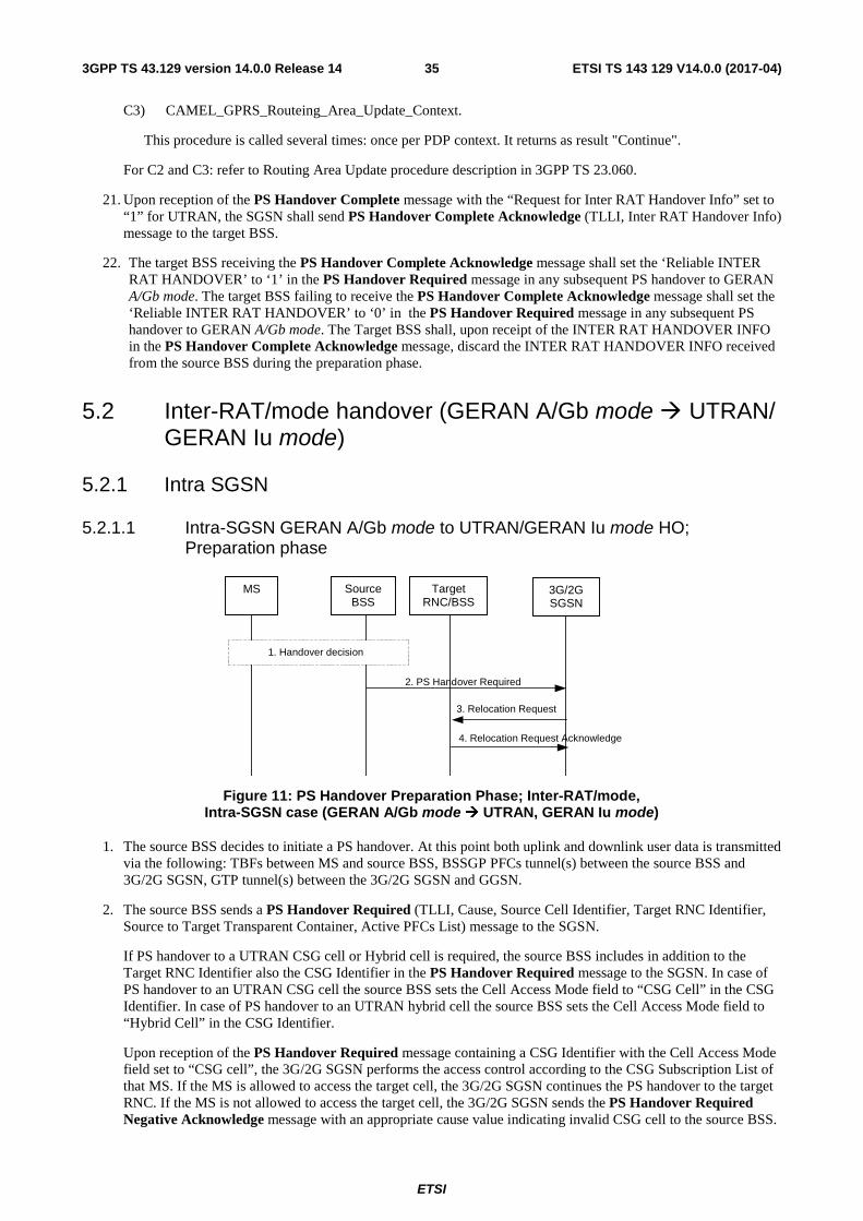
ETSI
ETSI TS 143 129 V14.0.0 (2017-04)353GPP TS 43.129 version 14.0.0 Release 14
C3) CAMEL_GPRS_Routeing_Area_Update_Context.
This procedure is called several times: once per PDP context. It returns as result "Continue".
For C2 and C3: refer to Routing Area Update procedure description in 3GPP TS 23.060.
21. Upon reception of the PS Handover Complete message with the “Request for Inter RAT Handover Info” set to “1” for UTRAN, the SGSN shall send PS Handover Complete Acknowledge (TLLI, Inter RAT Handover Info) message to the target BSS.
22. The target BSS receiving the PS Handover Complete Acknowledge message shall set the ‘Reliable INTER RAT HANDOVER’ to ‘1’ in the PS Handover Required message in any subsequent PS handover to GERAN A/Gb mode. The target BSS failing to receive the PS Handover Complete Acknowledge message shall set the ‘Reliable INTER RAT HANDOVER’ to ‘0’ in the PS Handover Required message in any subsequent PS handover to GERAN A/Gb mode. The Target BSS shall, upon receipt of the INTER RAT HANDOVER INFO in the PS Handover Complete Acknowledge message, discard the INTER RAT HANDOVER INFO received from the source BSS during the preparation phase.
5.2 Inter-RAT/mode handover (GERAN A/Gb mode � UTRAN/ GERAN Iu mode)
5.2.1 Intra SGSN
5.2.1.1 Intra-SGSN GERAN A/Gb mode to UTRAN/GERAN Iu mode HO; Preparation phase
Figure 11: PS Handover Preparation Phase; Inter-RAT/mode, Intra-SGSN case (GERAN A/Gb mode � UTRAN, GERAN Iu mode)
1. The source BSS decides to initiate a PS handover. At this point both uplink and downlink user data is transmitted via the following: TBFs between MS and source BSS, BSSGP PFCs tunnel(s) between the source BSS and 3G/2G SGSN, GTP tunnel(s) between the 3G/2G SGSN and GGSN.
2. The source BSS sends a PS Handover Required (TLLI, Cause, Source Cell Identifier, Target RNC Identifier, Source to Target Transparent Container, Active PFCs List) message to the SGSN.
If PS handover to a UTRAN CSG cell or Hybrid cell is required, the source BSS includes in addition to the Target RNC Identifier also the CSG Identifier in the PS Handover Required message to the SGSN. In case of PS handover to an UTRAN CSG cell the source BSS sets the Cell Access Mode field to “CSG Cell” in the CSG Identifier. In case of PS handover to an UTRAN hybrid cell the source BSS sets the Cell Access Mode field to “Hybrid Cell” in the CSG Identifier.
Upon reception of the PS Handover Required message containing a CSG Identifier with the Cell Access Mode field set to “CSG cell”, the 3G/2G SGSN performs the access control according to the CSG Subscription List of that MS. If the MS is allowed to access the target cell, the 3G/2G SGSN continues the PS handover to the target RNC. If the MS is not allowed to access the target cell, the 3G/2G SGSN sends the PS Handover Required Negative Acknowledge message with an appropriate cause value indicating invalid CSG cell to the source BSS.
2. PS Handover Required
4. Relocation Request Acknowledge
3. Relocation Request
1. Handover decision
MS Source BSS
Target RNC/BSS
3G/2G SGSN
ETSI
ETSI TS 143 129 V14.0.0 (2017-04)363GPP TS 43.129 version 14.0.0 Release 14
If the PS Handover Required message contains a CSG Identifier with the Cell Access Mode field set to “Hybrid Cell”, the 3G/2G SGSN provides the membership status of the MS and the CSG Id to the target RNC (see 3GPP TS25.413).
3. The 3G/2G SGSN determines from the Target RNC Identifier that the type of handover is inter-RAT/mode handover. In case of Inter-RAT/Intra-SGSN PS handover, the 3G/2G SGSN constructs a Relocation Request (Permanent NAS Identity, Cause, CN Domain Indicator, Integrity protection information (i.e. IK and allowed Integrity Protection algorithms, Encryption information (i.e. CK and allowed Ciphering algorithms), RABs To Be Set Up List, Source to Target Transparent Container, Iu Signalling connection identifier, Global CN-ID, SNA Access Information, UESBI-Iu) message to the target RNC/BSS.
For each RAB requested to be established, the RABs To Be Set Up List shall contain information such as RAB ID, RAB parameters, Transport Layer Address, and Iu Transport Association. The 3G/2G SGSN shall only request resources for RABs for which the corresponding PFC is included in the Active PFCs List. The RAB ID information element contains the NSAPI value, and the RAB parameters information element gives the QoS profile. The Transport Layer Address is the SGSN Address for user data, and the Iu Transport Association corresponds to the uplink Tunnel Endpoint Identifier Data. The SGSN may decide to establish a Direct Tunnel. In this case the SGSN provides to the target RNC the GGSN Address for User Plane and Uplink TEID for data.
Ciphering and integrity protection keys are sent to the target RNC/BSS to allow data transfer to continue in the new RAT/mode target cell without requiring a new AKA (Authentication and Key Agreement) procedure. Information that is required to be sent to the MS (either in the PS Handover Command message or after the handover completion message) from RRC in the target RNC/BSS shall be included in the RRC message sent from the target RNC/BSS to the MS via the transparent container.
In the target RNC/BSS radio and Iu user plane resources are reserved for the accepted RABs.
In case of PS handover to a CSG cell, the 3G/2G SGSN includes also the CSG ID in the Relocation Request message to the target RNC.
In case of PS handover to a Hybrid cell, the 3G/2G SGSN includes also the CSG ID and CSG Membership Status in the Relocation Request message to the target RNC. The target RNC may use the CSG Membership Status to perform differentiated treatment for CSG and non-CSG members (see 3GPP TS25.413).
4. The target RNC/BSS sends the Relocation Request Acknowledge (Target to Source Transparent Container, RABs setup list, RABs failed to setup list) message to the 3G/2G SGSN. Upon sending the Relocation Request Acknowledge message the target RNC/BSS shall be prepared to receive downlink GTP PDUs from the 3G/2G SGSN for the accepted RABs.
Each RAB to be setup is defined by a Transport Layer Address, which is the target RNC/BSS Address for user data, and the Iu Transport Association, which corresponds to the downlink Tunnel Endpoint Identifier for user data.
NOTE: The information to be included in the containers differs for UTRAN and GERAN Iu mode. For UTRAN, the information included in the container is related to RAB setup and other IE similar to those in the Handover to UTRAN message defined in 3GPP TS 25.331 [17]. For GERAN Iu mode the Radio Bearer Reconfiguration message defined in 3GPP TS 44.118 [16] is the RRC message to be included.
When the 3G/2G SGSN receives the Relocation Request Acknowledge message and it decides to proceed with the handover, the preparation phase is finished and the execution phase will follow.
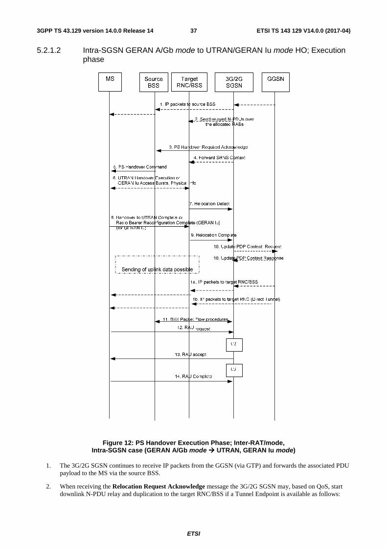
ETSI
ETSI TS 143 129 V14.0.0 (2017-04)373GPP TS 43.129 version 14.0.0 Release 14
5.2.1.2 Intra-SGSN GERAN A/Gb mode to UTRAN/GERAN Iu mode HO; Execution phase
Figure 12: PS Handover Execution Phase; Inter-RAT/mode, Intra-SGSN case (GERAN A/Gb mode � UTRAN, GERAN Iu mode)
1. The 3G/2G SGSN continues to receive IP packets from the GGSN (via GTP) and forwards the associated PDU payload to the MS via the source BSS.
2. When receiving the Relocation Request Acknowledge message the 3G/2G SGSN may, based on QoS, start downlink N-PDU relay and duplication to the target RNC/BSS if a Tunnel Endpoint is available as follows:
ETSI
ETSI TS 143 129 V14.0.0 (2017-04)383GPP TS 43.129 version 14.0.0 Release 14
• For PDP context, which uses LLC ADM, all new downlink N-PDUs received after completion of the PS handover preparation phase are relayed to the target RNC. All such N-PDUs are encapsulated in a GTP-PDU when transmitted to the target RNC/BSS.
• If the 3G/2G SGSN forwards downlink packets to the target RNC/BSS, the target RNC/BSS may start blind transmission of downlink user data towards the MS over the allocated radio channels.
3. The 3G/2G SGSN continues the PS Handover by sending a PS Handover Required Acknowledge (TLLI, List of Set Up PFCs, Target to Source Transparent Container) message to the source BSS.
Before sending the PS Handover Required Acknowledge message, the 3G/2G SGSN, based on QoS, may suspend downlink data transfer for any PDP contexts.
Before sending the PS Handover Command message to the MS the source BSS, based on QoS, may try to empty the downlink BSS buffer for any BSS PFCs.
4. The 3G/2G SGSN shall send the Forward SRNS Context (NSAPIDL GTP-U number, UL GTP-U number) message to the target RNC/BSS if there is at least one PDP context which requires "delivery order" to be preserved..NSAPI identifies the PDP context to which the GTP-U numbers apply The Forward SRNS Context message contains the sequence numbers of the GTP-PDU next to be transmitted in the uplink and downlink direction. After the Forward SRNS Context message is sent, further uplink N-PDUs received by the 3G/2G SGSN from the source BSS, relative to a PDP context which requires "delivery order" to be preserved, shall not be forwarded to the GGSN.
The GTP-U numbers are only sent by the 3G/2G SGSN for PDP context(s) requiring delivery order (QoS profile) to be preserved. If delivery order is to be preserved (QoS) profile), consecutive GTP-PDU sequence numbering shall be maintained through the lifetime of the PDP context(s).
Therefore, during the entire PS Handover procedure for the PDP context(s) using delivery order required (QoS profile), the responsible GTP-U entities (3G/2G SGSN, target RNC/BSS and GGSN) shall assign consecutive GTP-PDU sequence numbers to user packets belonging to the same PDP context uplink and downlink, respectively.
The target RNC/BSS proceed as follows:
• For RABs not requiring lossless PDCP the target RNC/BSS may, according the QoS profile of the PDP context, store the received data until it receives confirmation of MS presence in the target cell.
The further target RNC/BSS behaviour is as specified in 3GPP TS 23.060 [19] (Combined Hard Handover and SRNS Relocation).
5. The source BSS sends the PS Handover Command message containing the Handover to UTRAN Command message (as it is specified in 3GPP TS 25.331 [17]) or Radio Bearer Reconfiguration message (as it is specified in 3GPP TS 44.118 [16]) to the MS by interrupting the transmission of LLC PDUs on any of the downlink TBFs. Following the transmission of this signalling message the source BSS may resume LLC PDU transmission until it either has no more LLC PDUs to send or the PFC is released. Upon reception of the PS Handover Command the MS is not required to continue data reception in the source cell. Upon reception of the PS Handover Command the MS shall suspend the uplink transmission of user plane data. MS management of uplink N-PDUs following the reception of the PS Handover Command message is as follows:
• All N-PDUs associated with a PFC receiving handover treatment that have not yet been fully transmitted might be buffered depending on the QoS class.
• Subsequent uplink N-PDUs that become available for transmission following the reception of the PS Handover Command message might also be buffered depending on the QoS class.
• For real time services uplink N-PDUs may be discarded by the MS during the link interruption.
NOTE: Any buffering should be performed before the data is passed to SNDCP in order to avoid header compression on N-PDUs such that data delivery in the target cell may begin from the correct point in the sequence.
6. MS is in the target cell and performs access to UTRAN as defined in 3GPP TS 25.331 [17] and to GERAN Iu mode as defined in 3GPP TS 44.118 [16].
ETSI
ETSI TS 143 129 V14.0.0 (2017-04)393GPP TS 43.129 version 14.0.0 Release 14
7. The target RNC/BSS sends a Relocation Detect message to the 3G/2G SGSN to indicate that the MS is in the target cell. The message shall be sent when the relocation execution trigger is received. For SRNS relocation type "UE Involved", the relocation execution trigger may be received from the Uu interface; i.e. when the target RNC detects the MS on the lower layers. When the Relocation Detect message is sent, the target RNC shall start serving RNC operation.
8. In UTRAN, the MS sends Handover to UTRAN Complete {Message Type, UE Information elements (Start List, CN Domain Identity, Start), RB Information Elements (Count-C Activation Time)} message to the target RNC (see 3GPP TS 25.331 [17]).
In GERAN Iu, the MS sends Radio Bearer Reconfiguration Complete {RRC Transaction Identifier, Integrity Check Info, Uplink Integrity Protection Activation Info, COUNT-C Activation Time, Radio Bearer Uplink Ciphering Activation Time Info, Mobile Observed Time Difference, Uplink Counter Synchronisation Info struct, START List, CN Domain Identity, START, RB with PDCP Information List, RB with PDCP Information} message to target BSS.
9. When the new source RNC-ID + S-RNTI are successfully exchanged with the MS, the target RNC/BSS shall send the Relocation Complete message to the new SGSN. The purpose of the Relocation Complete procedure is to indicate by the target RNC/BSS the completion of the relocation of the source BSS to the CN. After the reception of the Relocation Complete message the 3G/2G SGSN shall be prepared to receive data from the target RNC/BSS.
10. If the SGSN has established Direct Tunnel, the SGSN sends an Update PDP Context Request (RNC Address, TEID, QoS Negotiated, DTI) message to the GGSN concerned. The SGSN provides to the GGSN the RNC address for the User Plane and TEID for downlink data and shall include the DTI to instruct the GGSN to apply Direct Tunnel specific error handling procedure as defined in 3GPP TS 23.060 [19]. The GGSN updates the PDP context fields and returns an Update PDP Context Response (TEID) message. From now on the GGSN sends new incoming downlink IP packets to the target RNC instead of the SGSN.
11. The 3G/2G SGSN shall initiate PFC Management procedures towards the source cell in order to trigger the release of resources in the source cell.
12. The MS sends a Routing Area Update Request (Old RAI, Old P-TMSI signature, Update Type) message to the 3G/2G SGSN. This is done even if the target cell belongs to the same routing area as the source cell. The MS shall send this message immediately after message 8. The 3G/2G SGSN knows that a handover has been performed for this MS and can therefore exclude the SGSN context procedures which normally are used within the RA Update procedure.
13. The 3G/2G SGSN validates the MS presence in the new RA. If the MS is allowed to be attached in this RA, the 3G/2G SGSN updates the MM context for and sends a Routing Area Update Accept message to the MS.
14. The MS may respond to the SGSN with a Routing Area Update Complete message.
The following CAMEL procedure calls shall be performed (see referenced procedures in TS 23.078 [8b]):
C2) CAMEL_GPRS_Routeing_Area_Update_Session and CAMEL_PS_Notification.
They are called in the following order:
- The CAMEL_GPRS_Routeing_Area_Update_Session procedure is called. The procedure returns as result "Continue".
- Then, the CAMEL_PS_Notification procedure is called. The procedure returns as result "Continue".
C3) CAMEL_GPRS_Routeing_Area_Update_Context.
This procedure is called several times: once per PDP context. It returns as result "Continue".
For C2 and C3: refer to Routing Area Update procedure description in 3GPP TS 23.060.
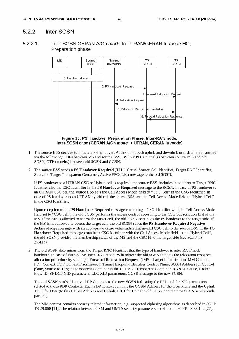
ETSI
ETSI TS 143 129 V14.0.0 (2017-04)403GPP TS 43.129 version 14.0.0 Release 14
5.2.2 Inter SGSN
5.2.2.1 Inter-SGSN GERAN A/Gb mode to UTRAN/GERAN Iu mode HO; Preparation phase
Figure 13: PS Handover Preparation Phase; Inter-RAT/mode, Inter-SGSN case (GERAN A/Gb mode � UTRAN, GERAN Iu mode)
1. The source BSS decides to initiate a PS handover. At this point both uplink and downlink user data is transmitted via the following: TBFs between MS and source BSS, BSSGP PFCs tunnel(s) between source BSS and old SGSN, GTP tunnel(s) between old SGSN and GGSN.
2. The source BSS sends a PS Handover Required (TLLI, Cause, Source Cell Identifier, Target RNC Identifier, Source to Target Transparent Container, Active PFCs List) message to the old SGSN.
If PS handover to a UTRAN CSG or Hybrid cell is required, the source BSS includes in addition to Target RNC Identifer also the CSG Identifier in the PS Handover Required message to the SGSN. In case of PS handover to an UTRAN CSG cell the source BSS sets the Cell Access Mode field to “CSG Cell” in the CSG Identifier. In case of PS handover to an UTRAN hybrid cell the source BSS sets the Cell Access Mode field to “Hybrid Cell” in the CSG Identifier.
Upon reception of the PS Handover Required message containing a CSG Identifier with the Cell Access Mode field set to “CSG cell”, the old SGSN performs the access control according to the CSG Subscription List of that MS. If the MS is allowed to access the target cell, the old SGSN continues the PS handover to the target side. If the MS is not allowed to access the target cell, the old SGSN sends the PS Handover Required Negative Acknowledge message with an appropriate cause value indicating invalid CSG cell to the source BSS. If the PS Handover Required message contains a CSG Identifier with the Cell Access Mode field set to “Hybrid Cell”, the old SGSN provides the membership status of the MS and the CSG Id to the target side (see 3GPP TS 25.413).
3. The old SGSN determines from the Target RNC Identifier that the type of handover is inter-RAT/mode handover. In case of inter-SGSN inter-RAT/mode PS handover the old SGSN initiates the relocation resource allocation procedure by sending a Forward Relocation Request (IMSI, Target Identification, MM Context, PDP Context, PDP Context Prioritisation, Tunnel Endpoint Identifier Control Plane, SGSN Address for Control plane, Source to Target Transparent Container in the UTRAN Transparent Container, RANAP Cause, Packet Flow ID, SNDCP XID parameters, LLC XID parameters, GCSI) message to the new SGSN.
The old SGSN sends all active PDP Contexts to the new SGSN indicating the PFIs and the XID parameters related to those PDP Contexts. Each PDP context contains the GGSN Address for the User Plane and the Uplink TEID for Data (to this GGSN Address and Uplink TEID for Data the old SGSN and the new SGSN send uplink packets).
The MM context contains security related information, e.g. supported ciphering algorithms as described in 3GPP TS 29.060 [11]. The relation between GSM and UMTS security parameters is defined in 3GPP TS 33.102 [27].
2. PS Handover Required
5. Relocation Request Acknowledge
3. Forward Relocation Request 4. Relocation Request
6. Forward Relocation Response
1. Handover decision
MS Source BSS
Target RNC/BSS
2G SGSN
3G SGSN
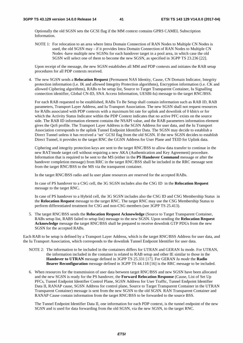
ETSI
ETSI TS 143 129 V14.0.0 (2017-04)413GPP TS 43.129 version 14.0.0 Release 14
Optionally the old SGSN sets the GCSI flag if the MM context contains GPRS CAMEL Subscription Information.
NOTE 1: For relocation to an area where Intra Domain Connection of RAN Nodes to Multiple CN Nodes is used, the old SGSN may - if it provides Intra Domain Connection of RAN Nodes to Multiple CN Nodes -have multiple new SGSNs for each handover target in a pool area, in which case the old SGSN will select one of them to become the new SGSN, as specified in 3GPP TS 23.236 [22].
Upon receipt of the message, the new SGSN establishes all MM and PDP contexts and initiates the RAB setup procedures for all PDP contexts received.
4. The new SGSN sends a Relocation Request (Permanent NAS Identity, Cause, CN Domain Indicator, Integrity protection information (i.e. IK and allowed Integrity Protection algorithms), Encryption information (i.e. CK and allowed Ciphering algorithms), RABs to be setup list, Source to Target Transparent Container, Iu Signalling connection identifier, Global CN-ID, SNA Access Information, UESBI-Iu) message to the target RNC/BSS.
For each RAB requested to be established, RABs To Be Setup shall contain information such as RAB ID, RAB parameters, Transport Layer Address, and Iu Transport Association. The new SGSN shall not request resources for RABs associated with PDP contexts with a maximum bit rate for uplink and downlink of 0 kbit/s or for which the Activity Status Indicator within the PDP Context indicates that no active PFC exists on the source side. The RAB ID information element contains the NSAPI value, and the RAB parameters information element gives the QoS profile. The Transport Layer Address is the SGSN Address for user data, and the Iu Transport Association corresponds to the uplink Tunnel Endpoint Identifier Data. The SGSN may decide to establish a Direct Tunnel unless it has received a ‘set’ GCSI flag from the old SGSN. If the new SGSN decides to establish Direct Tunnel, it provides to the target RNC the GGSN Address for User Plane and TEID for Uplink data.
Ciphering and integrity protection keys are sent to the target RNC/BSS to allow data transfer to continue in the new RAT/mode target cell without requiring a new AKA (Authentication and Key Agreement) procedure. Information that is required to be sent to the MS (either in the PS Handover Command message or after the handover completion message) from RRC in the target RNC/BSS shall be included in the RRC message sent from the target RNC/BSS to the MS via the transparent container.
In the target RNC/BSS radio and Iu user plane resources are reserved for the accepted RABs.
In case of PS handover to a CSG cell, the 3G SGSN includes also the CSG ID in the Relocation Request message to the target RNC.
In case of PS handover to a Hybrid cell, the 3G SGSN includes also the CSG ID and CSG Membership Status in the Relocation Request message to the target RNC. The target RNC may use the CSG Membership Status to perform differentiated treatment for CSG and non-CSG members (see 3GPP TS 25.413).
5. The target RNC/BSS sends the Relocation Request Acknowledge (Source to Target Transparent Container, RABs setup list, RABS failed to setup list) message to the new SGSN. Upon sending the Relocation Request Acknowledge message the target RNC/BSS shall be prepared to receive downlink GTP PDUs from the new SGSN for the accepted RABs.
Each RAB to be setup is defined by a Transport Layer Address, which is the target RNC/BSS Address for user data, and the Iu Transport Association, which corresponds to the downlink Tunnel Endpoint Identifier for user data.
NOTE 2: The information to be included in the containers differs for UTRAN and GERAN Iu mode. For UTRAN, the information included in the container is related to RAB setup and other IE similar to those in the Handover to UTRAN message defined in 3GPP TS 25.331 [17]. For GERAN Iu mode the Radio Bearer Reconfiguration message defined in 3GPP TS 44.118 [16] is the RRC message to be included.
6. When resources for the transmission of user data between target RNC/BSS and new SGSN have been allocated and the new SGSN is ready for the PS handover, the Forward Relocation Response (Cause, List of Set Up PFCs, Tunnel Endpoint Identifier Control Plane, SGSN Address for User Traffic, Tunnel Endpoint Identifier Data II, RANAP cause, SGSN Address for control plane, Source to Target Transparent Container in the UTRAN Transparent Container) message is sent from the new SGSN to the old SGSN. RAN Transparent Container and RANAP Cause contain information from the target RNC/BSS to be forwarded to the source BSS.
The Tunnel Endpoint Identifier Data II, one information for each PDP context, is the tunnel endpoint of the new SGSN and is used for data forwarding from the old SGSN, via the new SGSN, to the target RNC.
ETSI
ETSI TS 143 129 V14.0.0 (2017-04)423GPP TS 43.129 version 14.0.0 Release 14
When the old SGSN receives the Forward Relocation Response message and it decides to proceed with the handover, the preparation phase is finished and the execution phase will follow.
5.2.2.2 Inter-SGSN GERAN A/Gb mode to UTRAN/GERAN Iu mode HO; Execution phase
Figure 14: PS Handover Execution Phase; Inter-RAT/mode, Inter-SGSN case (GERAN A/Gb mode � UTRAN/GERAN Iu mode)
1. The old SGSN continues to receive IP packets from the GGSN (via GTP) and forwards the associated PDU payload to the MS via the source BSS.
2. When receiving the Forward Relocation Response message the old SGSN may, based on QoS, start downlink N-PDU relay and duplication to the target RNC/BSS via the new SGSN (if a Tunnel Endpoint is available) as follows:
• For PDP context, which uses LLC ADM in the old SGSN all new downlink N-PDUs received after completion of the PS handover preparation phase are relayed to the target RNC/BSS via the new SGSN. All such N-PDUs are encapsulated in a GTP-PDU when transmitted to the new SGSN.
If the old SGSN forwards downlink packets to the target RNC/BSS via the new SGSN, the target RNC/BSS may start blind transmission of downlink user data towards the MS over the allocated radio channels.
ETSI
ETSI TS 143 129 V14.0.0 (2017-04)433GPP TS 43.129 version 14.0.0 Release 14
NOTE 1: The order of steps, starting from step 2 onwards, does not necessarily reflect the order of events. For instance the old SGSN may start data forwarding (step 2), send the PS Handover Required Acknowledge message (step 4) and send the Forward SRNS context message (step 4a) almost simultaneously.
3. Void
4. The old SGSN continues the PS Handover by sending a PS Handover Required Acknowledge (TLLI, List of Set Up PFCs, Source to Target Transparent Container) message to the source BSS.
Before sending the PS Handover Required Acknowledge message, the old SGSN, based on QoS, may suspend downlink data transfer for any PDP contexts.
Before sending the PS Handover Command message to the MS the source BSS, based on QoS, may try to empty the downlink BSS buffer for any BSS PFCs.
4a. The old SGSN shall send the Forward SRNS Context message (NSAPI, DL GTP-U number, UL GTP-U number) to the new SGSN if there is at least one PDP context which requires "delivery order" to be preserved.NSAPI identifies the PDP context to which the GTP-U numbers apply. The Forward SRNS Context message is then acknowledged by the Forward SRNS Context Acknowledge message. The Forward SRNS Context message contains the sequence numbers of the GTP-PDU next to be transmitted in the uplink and downlink direction. After the Forward SRNS Context message is sent, further uplink N-PDUs received by the old SGSN from the source BSS, relative to a PDP context which requires "delivery order" to be preserved, shall not be forwarded to the GGSN.
The GTP-U numbers are only sent by the old SGSN for PDP context(s) requiring delivery order (QoS profile) to be preserved. If delivery order is to be preserved (QoS) profile), consecutive GTP-PDU sequence numbering shall be maintained through the lifetime of the PDP context(s).
Therefore, during the entire PS Handover procedure for the PDP context(s) using delivery order required (QoS profile), the responsible GTP-U entities (old SGSN, target RNC and GGSN) shall assign consecutive GTP-PDU sequence numbers to user packets belonging to the same PDP context uplink and downlink, respectively.
The target RNC proceed as follows:
• For RABs not requiring lossless PDCP the target RNC may, according the QoS profile of the PDP context, store the received data until it receives confirmation of MS presence in the target cell.
The further target RNC/BSS behaviour is as specified in 3GPP TS 23.060 [19] (Combined Hard Handover and SRNS Relocation).
5. The source BSS sends the PS Handover Command message containing the Handover to UTRAN Command message (as specified in 3GPP TS 25.331 [17]) or Radio Bearer Reconfiguration message (as specified in 3GPP TS 44.118 [16]) to the MS by interrupting the transmission of LLC PDUs on any of the downlink TBFs. Following the transmission of this signalling message the source BSS may resume LLC PDU transmission until it either has no more LLC PDUs to send or the PFC is released. Upon reception of the PS Handover Command message the MS is not required to continue data reception in the source cell. Upon reception of the PS Handover Command message the MS shall suspend the uplink transmission of user plane data. MS management of uplink N-PDUs following the reception of the PS Handover Command message is as follows:
• All N-PDUs associated with a PFC receiving handover treatment that have not yet been fully transmitted might be buffered depending on the QoS class.
• Subsequent uplink N-PDUs that become available for transmission following the reception of the PS Handover Command message might also be buffered depending on the QoS class.
• For real time services uplink N-PDUs may be discarded by the MS during the link interruption.
NOTE 2: Any buffering should be performed before the data is passed to SNDCP in order to avoid header compression on N-PDUs such that data delivery in the target cell may begin from the correct point in the sequence.
ETSI
ETSI TS 143 129 V14.0.0 (2017-04)443GPP TS 43.129 version 14.0.0 Release 14
6. MS is in the target cell and performs access to UTRAN as defined in 3GPP TS 25.331 [17] and to GERAN Iu mode as defined in 3GPP TS 44.118 [16].
7. Target RNC/BSS sends a Relocation Detect message to the new SGSN to indicate that the MS is in the target cell. The message shall be sent when the relocation execution trigger is received. For SRNS relocation type "UE Involved", the relocation execution trigger may be received from the Uu interface; i.e. when the target RNC detects the MS on the lower layers. When the Relocation Detect message is sent, the target RNC shall start serving RNC operation.
8. In UTRAN, MS sends Handover to UTRAN Complete {Message Type, UE Information elements (Start List, CN Domain Identity, Start), RB Information Elements (Count-C Activation Time)} message to the target RNC (see 3GPP TS 25.331 [17]).
In GERAN Iu, MS sends Radio Bearer Reconfiguration Complete {RRC Transaction Identifier, Integrity Check Info, Uplink Integrity Protection Activation Info, COUNT-C Activation Time, Radio Bearer Uplink Ciphering Activation Time Info, Mobile Observed Time Difference, Uplink Counter Synchronisation Info struct, START List, CN Domain Identity, START, RB with PDCP Information List, RB with PDCP Information} message to target BSS.
9. When the new source RNC-ID + S-RNTI are successfully exchanged with the MS, the target RNC/BSS shall send the Relocation Complete message to the new SGSN. The purpose of the Relocation Complete procedure is to indicate by the target RNC/BSS the completion of the relocation of the source BSS to the CN. After the reception of the Relocation Complete message the new SGSN shall be prepared to receive data from the target RNC/BSS. Each uplink N-PDU received by the new SGSN is forwarded directly to the GGSN.
10. For inter-SGSN PS handover, the new SGSN sends a Forward Relocation Complete message to the old SGSN to indicate the success of the handover procedure. The old SGSN acknowledges this with a Forward Relocation Complete Acknowledge message. Upon the reception of the Forward Relocation Complete message the old SGSN starts a packet forwarding timer. The old SGSN stops forwarding of data to the new SGSN after the packet forwarding timer expires.
11. The new SGSN sends an Update PDP Context Request (new SGSN Address, TEID, QoS Negotiated) message to the GGSN concerned. If a Direct Tunnel is established the SGSN provides to the GGSN instead of the new SGSN Address and TEID, the RNC address for User Plane and TEID for Downlink data and shall include the DTI to instruct the GGSN to apply Direct Tunnel specific error handling procedure as defined in 3GPP TS 23.060 [19]. The GGSN updates the PDP context fields and returns an Update PDP Context Response (TEID) message. From now on the GGSN sends new incoming downlink IP packets to the new SGSN instead of to the old SGSN.
12. The old SGSN shall initiate PFC Management procedures towards the source cell in order to trigger the release of resources in the source cell.
13. The MS sends a Routing Area Update Request (Old RAI, Old P-TMSI signature, Update Type) message to the new SGSN informing it that the target cell belongs to a new routing area. The MS shall send this message immediately after message 7. The new SGSN knows that a handover has been performed for this MS and can therefore exclude the SGSN context procedures which normally are used within the RA Update procedure.
14. At this point the new SGSN may optionally invoke MS authentication (security function). The security function can be deferred and performed at any later time as well.
NOTE 3: During an authentication procedure the SGSN has to suspend the downlink transmission of user data.
15. The new SGSN informs the HLR of the change of SGSN by sending Update Location (SGSN Number, SGSN Address, IMSI) message to the HLR.
16. The HLR sends Cancel Location (IMSI, Cancellation Type) message to the old SGSN with Cancellation Type set to Update Procedure.
17. The old SGSN acknowledges with a Cancel Location Acknowledge (IMSI) message. This message allows the old SGSN to know when to release the inter-SGSN tunnel.
18. The HLR sends Insert Subscriber Data (IMSI, GPRS subscription data) message to the new SGSN. The new SGSN validates the MS presence in the (new) RA.
ETSI
ETSI TS 143 129 V14.0.0 (2017-04)453GPP TS 43.129 version 14.0.0 Release 14
19. If all checks are successful then the new SGSN constructs an MM context for the MS and returns an Insert Subscriber Data Acknowledge (IMSI) message to the HLR. This message allows the new SGSN to know when to release the inter-SGSN tunnel.
20. The HLR acknowledges the Update Location by sending an Update Location Acknowledge (IMSI) message to the new SGSN.
21. The new SGSN validates the MS presence in the new RA. If the MS is allowed to be attached in this RA, the SGSN updates the MM context for and sends a Routing Area Update Accept message to the MS.
22. The MS may respond to the SGSN with a Routing Area Update Complete message.
The following CAMEL procedure calls shall be performed (see referenced procedures in TS 23.078 [8b])
C1) CAMEL_GPRS_PDP_Context_Disconnection, CAMEL_GPRS_Detach and CAMEL_PS_Notification.
They are called in the following order:
- The CAMEL_GPRS_PDP_Context_Disconnection procedure is called several times: once per PDP context. The procedure returns as result "Continue".
- Then the CAMEL_GPRS_Detach procedure is called once. The procedure returns as result "Continue".
- Then the CAMEL_PS_Notification procedure is called once. The procedure returns as result "Continue".
C2) CAMEL_GPRS_Routeing_Area_Update_Session and CAMEL_PS_Notification.
They are called in the following order:
- The CAMEL_GPRS_Routeing_Area_Update_Session procedure is called. The procedure returns as result "Continue".
- Then, the CAMEL_PS_Notification procedure is called. The procedure returns as result "Continue".
C3) CAMEL_GPRS_Routeing_Area_Update_Context.
This procedure is called several times: once per PDP context. It returns as result "Continue".
For C2 and C3: refer to Routing Area Update procedure description in 3GPP TS 23.060.
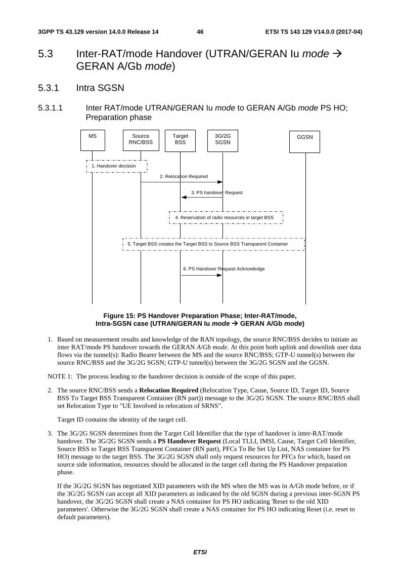
ETSI
ETSI TS 143 129 V14.0.0 (2017-04)463GPP TS 43.129 version 14.0.0 Release 14
5.3 Inter-RAT/mode Handover (UTRAN/GERAN Iu mode � GERAN A/Gb mode)
5.3.1 Intra SGSN
5.3.1.1 Inter RAT/mode UTRAN/GERAN Iu mode to GERAN A/Gb mode PS HO; Preparation phase
2. Relocation Required
6. PS Handover Request Acknowledge
3. PS handover Request
MS Source RNC/BSS
3G/2G SGSN
GGSN Target BSS
1. Handover decision
5. Target BSS creates the Target BSS to Source BSS Transparent Container
4. Reservation of radio resources in target BSS
Figure 15: PS Handover Preparation Phase; Inter-RAT/mode, Intra-SGSN case (UTRAN/GERAN Iu mode � GERAN A/Gb mode)
1. Based on measurement results and knowledge of the RAN topology, the source RNC/BSS decides to initiate an inter RAT/mode PS handover towards the GERAN A/Gb mode. At this point both uplink and downlink user data flows via the tunnel(s): Radio Bearer between the MS and the source RNC/BSS; GTP-U tunnel(s) between the source RNC/BSS and the 3G/2G SGSN; GTP-U tunnel(s) between the 3G/2G SGSN and the GGSN.
NOTE 1: The process leading to the handover decision is outside of the scope of this paper.
2. The source RNC/BSS sends a Relocation Required (Relocation Type, Cause, Source ID, Target ID, Source BSS To Target BSS Transparent Container (RN part)) message to the 3G/2G SGSN. The source RNC/BSS shall set Relocation Type to "UE Involved in relocation of SRNS".
Target ID contains the identity of the target cell.
3. The 3G/2G SGSN determines from the Target Cell Identifier that the type of handover is inter-RAT/mode handover. The 3G/2G SGSN sends a PS Handover Request (Local TLLI, IMSI, Cause, Target Cell Identifier, Source BSS to Target BSS Transparent Container (RN part), PFCs To Be Set Up List, NAS container for PS HO) message to the target BSS. The 3G/2G SGSN shall only request resources for PFCs for which, based on source side information, resources should be allocated in the target cell during the PS Handover preparation phase.
If the 3G/2G SGSN has negotiated XID parameters with the MS when the MS was in A/Gb mode before, or if the 3G/2G SGSN can accept all XID parameters as indicated by the old SGSN during a previous inter-SGSN PS handover, the 3G/2G SGSN shall create a NAS container for PS HO indicating 'Reset to the old XID parameters'. Otherwise the 3G/2G SGSN shall create a NAS container for PS HO indicating Reset (i.e. reset to default parameters).
ETSI
ETSI TS 143 129 V14.0.0 (2017-04)473GPP TS 43.129 version 14.0.0 Release 14
4. Based upon the ABQP for each PFC the target BSS makes a decision about which PFCs to assign radio resources. The algorithm by which the BSS decides which PFCs that need resources is implementation specific. Due to resource limitations not all downloaded PFCs will necessarily receive resource allocation. The target BSS allocates TBFs for each PFC that can be accommodated by the target BSS.
After allocating radio resources the target BSS shall prepare the Target BSS to Source BSS Transparent Container for the set up BSS PFCs.
5. The target BSS shall prepare the Target BSS to Source BSS Transparent Container which contains a PS Handover Command including the CN part (NAS container for PS HO) and the RN part (PS Handover Radio Resources).
6. The target BSS shall send the PS Handover Request Acknowledge message (Local TLLI, List of Set Up PFCs, Target BSS to Source BSS Transparent Container) message to the 3G/2G SGSN. Upon sending the PS Handover Request Acknowledge message the target BSS shall be prepared to receive downlink LLC PDUs from the 3G/2G SGSN for the accepted PFCs.
Any PDP contexts for which a PFC was not established are maintained in the 3G/2G SGSN and the related SAPIs and PFIs are kept. These PDP contexts may be modified or deactivated by the 3G/2G SGSN via explicit SM procedures upon the completion of the routing area update (RAU) procedure.
When the 3G/2G SGSN receives the PS Handover Request Acknowledge message and it decides to proceed with the handover, the preparation phase is finished and the execution phase will follow.

ETSI
ETSI TS 143 129 V14.0.0 (2017-04)483GPP TS 43.129 version 14.0.0 Release 14
5.3.1.2 Inter RAT/mode UTRAN/GERAN Iu mode to GERAN A/Gb mode PS HO; Execution phase
Figure 16: PS Handover Execution Phase; Inter-RAT/mode, Intra-SGSN case (UTRAN/GERAN Iu mode � GERAN A/Gb mode)
1. The 3G/2G SGSN continues to receive IP packets from the GGSN (via GTP) and forwards the associated PDU payload to the MS via the source RNC/BSS. In case of Direct Tunnel, the GGSN sends IP packets directly to the source RNC.
2. The 3G/2G SGSN continues the PS handover by sending a Relocation Command (Target BSS to Source BSS Transparent Container (PS Handover Command with RN part and CN part), RABs to be Released List, RABs Subject to Data Forwarding List) message to the source RNC/BSS. "RABs to be released list" will be the list of all NSAPIs (RAB Ids) for which a PFC was not established "RABs Subject to Data forwarding list" will be the list of all NSAPIs (RAB Ids) for which a PFC was established.
3. When receiving the Relocation Command message the source RNC may, based on QoS, begin the forwarding of data for the RABs subject to data forwarding to the 3G/2G SGSN according to the definition in 3GPP TS 23.060 [19]. The GTP-U sequence numbers are only sent by the source RNC for PDP context(s) requiring delivery order (QoS profile) to be preserved. If delivery order is to be preserved (QoS) profile), consecutive GTP-PDU sequence numbering shall be maintained through the lifetime of the PDP context(s).
The 3G/2G SGSN may, based on QoS, proceed with the packet handling as follows:
• For PDP contexts which use LLC ADM the 3G/2G SGSN either:
9. Updat e P DP Contex t request
2. Reloc at ion Com m and
4. H andov er from UT RAN Com m and or Handover fr om GER AN Iu Comm and
12. I u r elease Com mand
12 . Iu re lease Complete
1a. IP Pack ets fromGGSN
3. F or ward Data
3 . F orward GTP PDUs
3. F or ward Data
MS SourceRNC/BSS
TargetBSS
3G/2GSGSN
GGSN HLR
8. PS H andov er Com ple te
5. Forward SRNS Contex t
1a. IP Pack et s to s ourc e RN C/B SS
IP Pack et s t o target BSS
6. GERA N A/Gb A cc ess procedures
Sending of uplink data possible(LLC ADM only)
10 . XID negotia tion fo r LLC A DM
7. X ID R es ponse
13. RAU Reques t
14. RA U Ac cept
RAU Procedure
15 . RA U Complete
7a. XID Res ponse
11 . SAB M- UA Ex change
(AB M es tabl is hm ent and XID negotiation)
C2
C3
9. Update PDP Context Res ponse
1b. IP Packets to source RNC (Direct Tunnel)
16. PS Handover Com plet e A ck nowledge
ETSI
ETSI TS 143 129 V14.0.0 (2017-04)493GPP TS 43.129 version 14.0.0 Release 14
a. forwards the received downlink N-PDUs to the target BSS;
b. stores the received data into the SNDCP queue for e.g. the PDU lifetime;
c. discards the received data until e.g. reception of the PS Handover Complete message.
• If the 3G/2G SGSN forwards packets to the target BSS, the target BSS may start a blind transmission of downlink user data towards the MS over the allocated radio channels.
4. The RNC/BSS sends the Handover from UTRAN Command message (UTRAN) or the Handover from GERAN Iu Command message to the MS where each message includes a PS Handover Command (RN part and CN part) message. Before sending the message the uplink and downlink data transfer shall be suspended in the source RNC for the RABs that require delivery order.
Upon reception of the Handover from UTRAN Command message (UTRAN) or the Handover from GERAN Iu Command the MS shall suspend the uplink transmission of user plane data.
5. The source RNC/BSS continues the handover by sending a Forward SRNS Context (RAB contexts) message to the 3G/2G SGSN.
The source RNC/BSS behaviour is as specified in 3GPP TS 23.060 [19] (Combined Hard Handover and SRNS Relocation).
6. The MS executes the handover according to the parameters provided in the message delivered in step 4. The procedure is the same as in step 6 in subclause 5.1.4.2.
7./7a. After accessing the cell using access bursts and receiving timing advance information from the BSS in step 6, the MS processes the NAS container and then sends one XID Response message to the 3G/2G SGSN The MS sends this message immediately after receiving the Packet Physical Information message containing the timing advance or, in the synchronised network case, immediately if the PS Handover Access message is not required to be sent (see Section 6.2).
The MS shall resume the user data transfer only for those NSAPIs for which there are radio resources allocated in the target cell. For NSAPIs using LLC ADM for which radio resources were not allocated in the target cell the MS may request for radio resources using the legacy procedures.
NOTE: If the 3G/2G SGSN indicated Reset (i.e. reset to default parameters) in the NAS container for PS HO included in the Handover from UTRAN Command message (UTRAN) or the Handover from GERAN Iu Command message, in order to avoid collision cases the mobile station may avoid triggering XID negotiation for any LLC SAPI used in LLC ADM, but wait for the SGSN to do so (see bullet 9). In any case the mobile station may avoid triggering XID negotiation for any LLC SAPI used in LLC ABM, but wait for the SGSN to do so (see bullet 10).
8. Upon reception of the first correct RLC/MAC block (sent in normal burst format) from the MS the target BSS sends a PS Handover Complete (Local TLLI, IMSI, Request for Inter RAT Handover Info) message to inform the 3G/2G SGSN that the MS has arrived in the target cell. Each uplink N-PDU received by the 3G/2G SGSN via the target BSS is then forwarded directly to the GGSN. The target BSS shall request the INTER RAT HANDOVER INFO from the SGSN by setting the “Request for INTER RAT HANDOVER INFO” to “1”.
9. If a Direct Tunnel was established for Iu mode, the SGSN sends an Update PDP Context Request (new SGSN Address, TEID, QoS Negotiated) message to the GGSN with the indication for not re-negotiating the QoS and to establish a tunnel between the SGSN and the GGSN. The GGSN updates the PDP context and returns an Update PDP Context Response (TEID) message. From now on the GGSN sends new incoming downlink IP packets to the SGSN.
10. If the 3G/2G SGSN indicated Reset (i.e. reset to default parameters) in the NAS container for PS HO included in the Handover from UTRAN Command message (UTRAN) or the Handover from GERAN Iu Command message, then on receipt of the PS Handover Complete message the SGSN initiates an LLC/SNDCP XID negotiation for each LLC SAPI used in LLC ADM. In this case if the SGSN wants to use the default parameters, it shall send an empty XID Command. If the SGSN indicated 'Reset to the old XID parameters' in the NAS container for PS HO, no further XID negotiation is required for LLC SAPIs used in LLC ADM only.
ETSI
ETSI TS 143 129 V14.0.0 (2017-04)503GPP TS 43.129 version 14.0.0 Release 14
11. The 3G/2G SGSN (re-)establishes LLC ABM for the PDP contexts which use acknowledged information transfer. During the exchange of SABM and UA the SGSN shall perform LLC/SNDCP XID negotiation.
12. After the reception of the PS Handover Complete message the 3G/2G SGSN sends an Iu Release Command message to the source RNC/BSS commanding the source RNC/BSS to release all resources related to the Iu connection. When the RNC/BSS data forwarding timer has expired the source RNC/BSS responds with an Iu Release Complete (RAB Data Volume report list, RABs released list) message.
13. The MS sends a Routing Area Update Request (Old P-TMSI, Old RAI, Old P-TMSI signature, Update Type) message to the 3G/2G SGSN. This is done even if the target cell belongs to the same routing area as the source cell. The MS shall send this message immediately after message 7, see 3GPP TS 23.060 [19].
The 3G/2G SGSN knows that a handover has been performed for this MS and can therefore exclude the SGSN context procedures which normally are used within the RA Update procedure.
14. The 3G/2G SGSN validates the MS presence in the new RA. If the MS is allowed to be attached in this RA, the 3G/2G SGSN updates the MM context for and sends a Routing Area Update Accept (P-TMSI, TMSI, P-TMSI signature, Receive N-PDU number) message to the MS. The Receive N-PDU Number contains the acknowledgements for each acknowledged-mode NSAPI used by the 3G/2G SGSN, thereby confirming all mobile originated N-PDUs successfully transferred before the start of the PS handover procedure.
15. The MS confirms the re-allocation of the new P-TMSI by responding to the 3G/2G SGSN with a Routing Area Update Complete (Receive N-PDU number). The MS derives the TLLI from the new P-TMSI using the current MM procedures. The Receive N-PDU Number contains the acknowledgements for each acknowledged mode NSAPI used by the MS, thereby confirming all mobile terminated N-PDUs successfully transferred before the start of the handover procedure. If Receive N-PDU Number confirms reception of N-PDUs that were forwarded from the 3G/2G SGSN, these N-PDUs shall be discarded by the 3G/2G SGSN.
The following CAMEL procedure calls shall be performed (see referenced procedures in TS 23.078 [8b]):
C2) CAMEL_GPRS_Routeing_Area_Update_Session and CAMEL_PS_Notification.
They are called in the following order:
- The CAMEL_GPRS_Routeing_Area_Update_Session procedure is called. The procedure returns as result "Continue".
- Then, the CAMEL_PS_Notification procedure is called. The procedure returns as result "Continue".
C3) CAMEL_GPRS_Routeing_Area_Update_Context.
This procedure is called several times: once per PDP context. It returns as result "Continue".
For C2 and C3: refer to Routing Area Update procedure description in 3GPP TS 23.060.
16. Upon reception of the PS Handover Complete message with the “Request for Inter RAT Handover Info” set to “1” for UTRAN, the SGSN shall send PS Handover Complete Acknowledge (TLLI, Inter RAT Handover Info) message to the target BSS.
17. The target BSS receiving the PS Handover Complete Acknowledge message shall set the ‘Reliable INTER RAT HANDOVER’ to ‘1’ in the PS Handover Required message in any subsequent PS handover to GERAN A/Gb mode. The target BSS failing to receive the PS Handover Complete Acknowledge message shall set the ‘Reliable INTER RAT HANDOVER’ to ‘0’ in the PS Handover Required message in any subsequent PS handover to GERAN A/Gb mode. The Target BSS shall, upon receipt of the INTER RAT HANDOVER INFO in the PS Handover Complete Acknowledge message, discard the INTER RAT HANDOVER INFO received from the source RNC during the preparation phase.
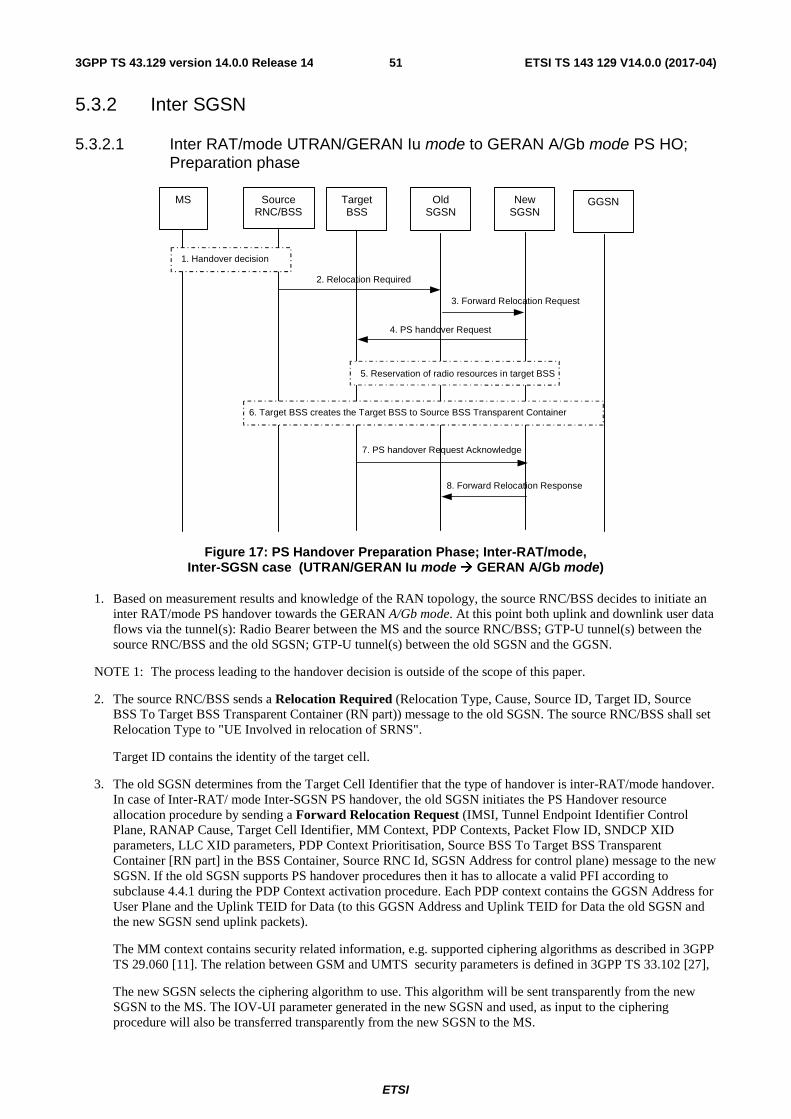
ETSI
ETSI TS 143 129 V14.0.0 (2017-04)513GPP TS 43.129 version 14.0.0 Release 14
5.3.2 Inter SGSN
5.3.2.1 Inter RAT/mode UTRAN/GERAN Iu mode to GERAN A/Gb mode PS HO; Preparation phase
2. Relocation Required
7. PS handover Request Acknowledge
3. Forward Relocation Request
4. PS handover Request
MS Source RNC/BSS
Old SGSN
New SGSN
GGSN Target BSS
1. Handover decision
8. Forward Relocation Response
6. Target BSS creates the Target BSS to Source BSS Transparent Container
5. Reservation of radio resources in target BSS
Figure 17: PS Handover Preparation Phase; Inter-RAT/mode, Inter-SGSN case (UTRAN/GERAN Iu mode � GERAN A/Gb mode)
1. Based on measurement results and knowledge of the RAN topology, the source RNC/BSS decides to initiate an inter RAT/mode PS handover towards the GERAN A/Gb mode. At this point both uplink and downlink user data flows via the tunnel(s): Radio Bearer between the MS and the source RNC/BSS; GTP-U tunnel(s) between the source RNC/BSS and the old SGSN; GTP-U tunnel(s) between the old SGSN and the GGSN.
NOTE 1: The process leading to the handover decision is outside of the scope of this paper.
2. The source RNC/BSS sends a Relocation Required (Relocation Type, Cause, Source ID, Target ID, Source BSS To Target BSS Transparent Container (RN part)) message to the old SGSN. The source RNC/BSS shall set Relocation Type to "UE Involved in relocation of SRNS".
Target ID contains the identity of the target cell.
3. The old SGSN determines from the Target Cell Identifier that the type of handover is inter-RAT/mode handover. In case of Inter-RAT/ mode Inter-SGSN PS handover, the old SGSN initiates the PS Handover resource allocation procedure by sending a Forward Relocation Request (IMSI, Tunnel Endpoint Identifier Control Plane, RANAP Cause, Target Cell Identifier, MM Context, PDP Contexts, Packet Flow ID, SNDCP XID parameters, LLC XID parameters, PDP Context Prioritisation, Source BSS To Target BSS Transparent Container [RN part] in the BSS Container, Source RNC Id, SGSN Address for control plane) message to the new SGSN. If the old SGSN supports PS handover procedures then it has to allocate a valid PFI according to subclause 4.4.1 during the PDP Context activation procedure. Each PDP context contains the GGSN Address for User Plane and the Uplink TEID for Data (to this GGSN Address and Uplink TEID for Data the old SGSN and the new SGSN send uplink packets).
The MM context contains security related information, e.g. supported ciphering algorithms as described in 3GPP TS 29.060 [11]. The relation between GSM and UMTS security parameters is defined in 3GPP TS 33.102 [27],
The new SGSN selects the ciphering algorithm to use. This algorithm will be sent transparently from the new SGSN to the MS. The IOV-UI parameter generated in the new SGSN and used, as input to the ciphering procedure will also be transferred transparently from the new SGSN to the MS.
ETSI
ETSI TS 143 129 V14.0.0 (2017-04)523GPP TS 43.129 version 14.0.0 Release 14
When the new SGSN receives the Forward Relocation Request message the required PDP, MM, SNDCP and LLC contexts are established and a new P-TMSI is allocated for the MS. When this message is received by the new SGSN it begins the process of establishing PFCs for all PDP contexts.
When the new SGSN receives the Forward Relocation Request message it extracts from the PDP Contexts the NSAPIs and SAPIs and PFIs to be used in the new SGSN. If for a given PDP Context the new SGSN does not receive a PFI from the old SGSN, it shall not request the target BSS to allocate TBF resources corresponding to that PDP Context. If none of the PDP Contexts forwarded from the old SGSN has a valid PFI allocated the new SGSN shall consider this as a failure case and the request for PS handover shall be rejected.
In case when an SAPI and PFI was available at the old SGSN but the new SGSN does not support the same SAPI and PFI for a certain NSAPI as the old SGSN, the new SGSN shall continue the PS handover procedure only for those NSAPIs for which it can support the same PFI and SAPI as the old SGSN. All PDP contexts for which no resources are allocated by the new SGSN or for which it cannot support the same SAPI and PFI (i.e. the corresponding NSAPIs are not addressed in the response message of the target SGSN), are maintained and the related SAPIs and PFIs are kept. These PDP contexts may be modified or deactivated by the new SGSN via explicit SM procedures upon RAU procedure.
The old SGSN shall indicate the current XID parameter settings if available (i.e. those negotiated at the old SGSN when the MS was in A/Gb mode or received during a previous inter-SGSN PS handover) to the new SGSN. If the new SGSN can accept all XID parameters as indicated by the old SGSN, the new SGSN shall create a NAS container for PS HO indicating 'Reset to the old XID parameters'. Otherwise, if the new SGSN cannot accept all XID parameters indicated by the old SGSN or if no XID parameters were indicated by the old SGSN, the new SGSN shall create a NAS container for PS HO indicating Reset (i.e. reset to default parameters).
4. The new SGSN sends a PS Handover Request (Local TLLI, IMSI, Cause, Target Cell Identifier, Source BSS to Target BSS Transparent Container (RN part), PFCs To Be Set Up List, NAS container for PS HO) message to the target BSS. The new SGSN shall not request resources for PFCs associated with PDP contexts with maximum bit rate for uplink and downlink of 0 kbit/s or for which the Activity Status Indicator within the PDP Context indicates that no active RAB exists on the source side.
5. Based upon the ABQP for each PFC the target BSS makes a decision about which PFCs to assign radio resources. The algorithm by which the BSS decides which PFCs that need resources is implementation specific. Due to resource limitations not all downloaded PFCs will necessarily receive resource allocation. The target BSS allocates TBFs for each PFC that it can accommodate.
6. The target BSS shall prepare the Target BSS to Source BSS Transparent Container which contains a PS Handover Command including the CN part (NAS container for PS HO) and the RN part (PS Handover Radio Resources).
7. Target BSS shall send the PS Handover Request Acknowledge message (Local TLLI, List of Set Up PFCs, Target BSS to Source BSS Transparent Container) message to the new SGSN. Upon sending the PS Handover Request Acknowledge message the target BSS shall be prepared to receive downlink LLC PDUs from the new SGSN for the accepted PFCs.
Any PDP contexts for which a PFC was not established are maintained in the new SGSN and the related SAPIs and PFIs are kept. These PDP contexts may be modified or deactivated by the new SGSN via explicit SM procedures upon the completion of the routing area update (RAU) procedure.
8. The new SGSN passes the assigned list of TEIDs for each PDP context for which a PFC was assigned in the RAB setup information IE in the Forward Relocation Response (Cause, List of Set Up PFCs, Target BSS to Source BSS Transparent Container) in the BSS Container, Tunnel Endpoint Identifier Control Plane, SGSN Address for User Traffic, Tunnel Endpoint Identifier Data II) message to the old SGSN. The NSAPIs of the active PDP Contexts received in the Forward Relocation Request message for which the PS handover continues, i.e. for which resources are allocated for the PFCs in the target BSS, are indicated in this message. The Tunnel Endpoint Identifier Data II, one information for each PDP context, is the tunnel endpoint of the new SGSN and is used for data forwarding from the old SGSN, via the new SGSN, to the target BSS.
The new SGSN activates the allocated LLC/SNDCP engines as specified in 3GPP TS 44.064 [21] for an SGSN originated Reset or 'Reset to the old XID parameters'.
When the old SGSN receives the Forward Relocation Response message and it decides to proceed with the handover, the preparation phase is finished and the execution phase will follow.
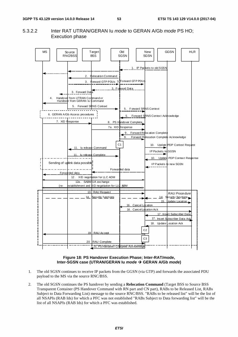
ETSI
ETSI TS 143 129 V14.0.0 (2017-04)533GPP TS 43.129 version 14.0.0 Release 14
5.3.2.2 Inter RAT UTRAN/GERAN Iu mode to GERAN A/Gb mode PS HO; Execution phase
Figure 18: PS Handover Execution Phase; Inter-RAT/mode, Inter-SGSN case (UTRAN/GERAN Iu mode � GERAN A/Gb mode)
1. The old SGSN continues to receive IP packets from the GGSN (via GTP) and forwards the associated PDU payload to the MS via the source RNC/BSS.
2. The old SGSN continues the PS handover by sending a Relocation Command (Target BSS to Source BSS Transparent Container (PS Handover Command with RN part and CN part), RABs to be Released List, RABs Subject to Data Forwarding List) message to the source RNC/BSS. "RABs to be released list" will be the list of all NSAPIs (RAB Ids) for which a PFC was not established "RABs Subject to Data forwarding list" will be the list of all NSAPIs (RAB Ids) for which a PFC was established.
2. Relocat ion Command
4. Handover from UTRAN Command or Handover from GERAN Iu Command
1. IP Packets to old SGSN
3. Forward Data
3 . Forward GTP PDUs
3. Forward Data
MS SourceRNC/BSS
TargetBSS
OldSGSN
NewSGSN
GGSN HLR
8. PS Handover Complete7. XID Response
6. GERAN A/Gb Access procedures
10. Update PDP Context Request
10. Update PDP Contex t Response
9 . Forward Relocation Complete
9. Forward Relocation Complete Acknowledge
IP Packets to new SGSN
15. Update Locat ion
13. RAU Reques t
14. Security funct ions 14. Security functionsRAU Procedure
16 . Cancel Locat ion Ack
17 . Insert Subscriber Data
17. Insert Subscriber Data Ack
18. Update Locat ion Ack
19.
RAU Accept
20.
RAU Complete
16 . Cancel Location
5 . Forward SRNS Context5 . F orward SRNS Context
5. Forward SRNS Contex t Acknowledge
Sending of uplink data possible
12 . XID negotiat ion for LLC ADM
7a. XID Response
IP Packets to GGSN11. Iu release Command
11. Iu release Complete
12a . SABM UA exchange (re- es tablishment and XID negotiation for LLC ABM)
Forwarded dataForwarded data
C1
C2
C3
Forward GTP PDUs3.
. 21. PS Handover Complete Acknowledge
ETSI
ETSI TS 143 129 V14.0.0 (2017-04)543GPP TS 43.129 version 14.0.0 Release 14
3. When receiving the Relocation Command message the source RNC/BSS may, based on QoS, begin the forwarding of data for the RABs subject to data forwarding to the new SGSN via the old SGSN (if a Tunnel Endpoint is available) according to the definition in 3GPP TS 23.060 [19]. The GTP-U sequence numbers are only sent by the source RNC for PDP context(s) requiring delivery order (QoS profile) to be preserved. If delivery order is to be preserved (QoS) profile), consecutive GTP-PDU sequence numbering shall be maintained through the lifetime of the PDP context(s).
The new SGSN may, based on QoS, proceed with the packet handling as follows:
• For PDP contexts which use LLC ADM the new SGSN either:
a. forwards the received downlink N-PDUs to the target BSS;
b. stores the received data into the SNDCP queue for e.g. the PDU lifetime;
c. discards the received data until e.g. reception of the PS Handover Complete message.
If the new SGSN forwards packets to the target BSS, the target BSS may start a blind transmission of downlink user data towards the MS over the allocated radio channels.
NOTE 1: The order of steps, starting from step 3 onwards, does not necessarily reflect the order of events. For instance the source RNC may start data forwarding (step 3), send the RRC message (step 4) and send the Forward SRNS Context message (step 5) almost simultaneously.
4. The source RNC/BSS sends the Handover from UTRAN Command message (UTRAN) or the Handover from GERAN Iu Command message to the MS where each message includes a PS Handover Command (RN part and CN part). Before sending the message the uplink and downlink data transfer shall be suspended in the source RNC for the RABs that require delivery order.
Upon the reception of the HANDOVER from UTRAN Command message (UTRAN) or the HANDOVER from GERAN Iu Command message containing the PS Handover Command message, the MS shall associate its RAB IDs to the respective PFIs based on the relation with the NSAPI and shall suspend the uplink transmission of the user plane data.
5. The source RNC continues the handover by sending a Forward SRNS Context (RAB contexts) message to the new SGSN, via the old SGSN. The Forward SRNS Context message is acknowledged by the new SGSN with the Forward SRNS Context Acknowledge message to the old SGSN.
The source RNC/BSS behaviour is as specified in 3GPP TS 23.060 [19] (Combined Hard Handover and SRNS Relocation).
6. The MS executes the handover according to the parameters provided in the message delivered in step 4. The procedure is the same as in step 6 in subclause 5.1.4.2 with the additional function of association of the received PFI and existing RAB Id related to the particular NSAPI as described in clause 4.4.1.
7./7a. After accessing the cell using access bursts and receiving timing advance information from the BSS in step 6, the MS processes the NAS container and then sends one XID Response message to the new SGSN . The MS sends this message immediately after receiving the Packet Physical Information message containing the timing advance or, in the synchronised network case, immediately if the PS Handover Access message is not required to be sent (see Section 6.2).
Upon sending the XID Response message, the MS shall resume the user data transfer only for those NSAPIs for which there are radio resources allocated in the target cell. For NSAPIs using LLC ADM for which radio resources were not allocated in the target cell the MS may request for radio resources using the legacy procedures.
NOTE 2: If the new SGSN indicated Reset (i.e. reset to default parameters) in the NAS container for PS HO included in the the Handover from UTRAN Command message (UTRAN) or the Handover from GERAN Iu Command message, in order to avoid collision cases the mobile station may avoid triggering XID negotiation for any LLC SAPI used in LLC ADM, but wait for the SGSN to do so (see bullet 12). In any case the mobile station may avoid triggering XID negotiation for any LLC SAPI used in LLC ABM, but wait for the SGSN to do so (see bullet 12a).
8. Upon reception of the first correct RLC/MAC block (sent in normal burst format) from the MS the target BSS sends a PS Handover Complete (Local TLLI, Handover Complete Status, Request for Inter RAT Handover
ETSI
ETSI TS 143 129 V14.0.0 (2017-04)553GPP TS 43.129 version 14.0.0 Release 14
Info) message to inform the new SGSN that the MS has arrived in the target cell. Each uplink N-PDU received by the new SGSN via the target BSS is then forwarded directly to the GGSN. The target BSS shall request the INTER RAT HANDOVER INFO from the SGSN by setting the ‘Request for Inter RAT Handover Info’ to ‘1’.
9. Upon receiving the PS Handover Complete message, the new SGSN send a Forward Relocation Complete message to the old SGSN to indicate completion of the PS handover procedures. The old SGSN responds with a Forward Relocation Complete Acknowledge message.
10. The new SGSN sends an Update PDP Context Request (new SGSN Address, TEID, QoS Negotiated) message to the GGSN concerned. The GGSN updates the PDP context fields and returns an Update PDP Context Response (TEID) message. From now on the GGSN sends new incoming downlink IP packets to the new SGSN instead of to the old SGSN.
11. The old SGSN sends an Iu Release Command message to the source RNC/BSS commanding the source RNC/BSS to release all resources related to the Iu connection. When the RNC/BSS data forwarding timer has expired the source RNC/BSS responds with an Iu Release Complete (RAB Data Volume report list, RABs released list) message.
12. If the new SGSN indicated Reset (i.e. reset to default parameters) in the NAS container for PS HO included in the Handover from UTRAN Command message (UTRAN) or the Handover from GERAN Iu Command message, then on receipt of the PS Handover Complete the new SGSN initiates an LLC/SNDCP XID negotiation for each LLC SAPI used in LLC ADM. In this case if the SGSN wants to use the default parameters, it shall send an empty XID Command. If the new SGSN indicated 'Reset to the old XID parameters' in the NAS container for PS HO, no further XID negotiation is required for LLC SAPIs used in LLC ADM only.
12a. The new SGSN (re-)establishes LLC ABM for the PDP contexts which use acknowledged information transfer. During the exchange of SABM and UA the SGSN shall perform LLC/SNDCP XID negotiation.
13. The MS sends a Routing Area Update Request (Old P-TMSI, Old RAI, Old P-TMSI signature, Update Type) message to the new SGSN informing it that the source cell belongs to a new routing area. The MS shall send this message immediately after message 7, see 3GPP TS 23.060 [19].
The new SGSN knows that a handover has been performed for this MS and can therefore exclude the SGSN context procedures which normally are used within the RA Update procedure.
14. At this point the new SGSN may optionally invoke MS authentication (security function). The security function can be deferred and performed at any later time as well.
NOTE 3: During an authentication procedure the SGSN has to suspend the downlink transmission of user data.
15. The new SGSN informs the HLR of the change of SGSN by sending Update Location (SGSN Number, SGSN Address, IMSI) message to the HLR.
16. The HLR sends a Cancel Location (IMSI, Cancellation Type) message to the old SGSN with Cancellation Type set to Update Procedure. The old SGSN acknowledges with a Cancel Location Acknowledge (IMSI) message. This message allows the old SGSN to know when to release the inter-SGSN tunnel.
17. The HLR sends Insert Subscriber Data (IMSI, GPRS subscription data) message to the new SGSN. The new SGSN validates the MS presence in the (new) RA. If all checks are successful then the new SGSN constructs an MM context for the MS and returns an Insert Subscriber Data Acknowledge (IMSI) message to the HLR. This message allows the new SGSN to know when to release the inter-SGSN tunnel.
18. The HLR acknowledges the Update Location by sending an Update Location Acknowledge (IMSI) message to the new SGSN.
19. The new SGSN validates the MS presence in the new RA. If the MS is allowed to be attached in this RA, the SGSN updates the MM context for and sends a Routing Area Update Accept (P-TMSI, TMSI, P-TMSI signature, Receive N-PDU number) message to the MS. The Receive N-PDU Number contains the acknowledgements for each acknowledged-mode NSAPI used by the SGSN, thereby confirming all mobile originated N-PDUs successfully transferred before the start of the PS handover procedure.
20. The MS confirms the re-allocation of the new P-TMSI by responding to the SGSN with a Routing Area Update Complete (Receive N-PDU number) message. The MS derives the Local TLLI from the new P-TMSI using the current MM procedures. The Receive N-PDU Number contains the acknowledgements for each
ETSI
ETSI TS 143 129 V14.0.0 (2017-04)563GPP TS 43.129 version 14.0.0 Release 14
acknowledged mode NSAPI used by the MS, thereby confirming all mobile terminated N-PDUs successfully transferred before the start of the handover procedure. If Receive N-PDU Number confirms reception of N-PDUs that were forwarded from the old SGSN, these N-PDUs shall be discarded by the new SGSN.
The following CAMEL procedure calls shall be performed (see referenced procedures in TS 23.078 [8b])
C1) CAMEL_GPRS_PDP_Context_Disconnection, CAMEL_GPRS_Detach and CAMEL_PS_Notification.
They are called in the following order:
- The CAMEL_GPRS_PDP_Context_Disconnection procedure is called several times: once per PDP context. The procedure returns as result "Continue".
- Then the CAMEL_GPRS_Detach procedure is called once. The procedure returns as result "Continue"
- Then the CAMEL_PS_Notification procedure is called once. The procedure returns as result "Continue".
C2) CAMEL_GPRS_Routeing_Area_Update_Session and CAMEL_PS_Notification.
They are called in the following order:
- The CAMEL_GPRS_Routeing_Area_Update_Session procedure is called. The procedure returns as result "Continue".
- Then, the CAMEL_PS_Notification procedure is called. The procedure returns as result "Continue".
C3) CAMEL_GPRS_Routeing_Area_Update_Context.
This procedure is called several times: once per PDP context. It returns as result "Continue".
For C2 and C3: refer to Routing Area Update procedure description in 3GPP TS 23.060.
21. Upon reception of the PS Handover Complete message with the “Request for Inter RAT Handover Info” set to “1” for UTRAN, the SGSN shall send PS Handover Complete Acknowledge (TLLI, Inter RAT Handover Info) message to the target BSS.
22. The target BSS receiving the PS Handover Complete Acknowledge message shall set the ‘Reliable INTER RAT HANDOVER’ to ‘1’ in the PS Handover Required message in any subsequent PS handover to GERAN A/Gb mode. The target BSS failing to receive the PS Handover Complete Acknowledge message shall set the ‘Reliable INTER RAT HANDOVER’ to ‘0’ in the PS Handover Required message in any subsequent PS handover to GERAN A/Gb mode. The Target BSS shall, upon receipt of the INTER RAT HANDOVER INFO in the PS Handover Complete Acknowledge message, discard the INTER RAT HANDOVER INFO received from the source RNC during the preparation phase.
5.3a Inter-RAT Handover (GERAN A/Gb mode to E-UTRAN)
5.3a.1 General
This procedure and the corresponding signalling flows are defined in 3GPP TS23.401 [33].
For performing the inter-RAT handover from GERAN A/Gb mode to E-UTRAN the pre-conditions are:
- The MS is in packet transfer mode (GERAN A/Gb mode);
- The MS has at least one PDP Context established;
- The BSS supports PFM (Packet Flow Management) procedures.
5.3a.2 Preparation phase
The detailed signalling flows are specified in 3GPP TS 23.401 [33] in sub-clause 5.5.2.4.2.
ETSI
ETSI TS 143 129 V14.0.0 (2017-04)573GPP TS 43.129 version 14.0.0 Release 14
5.3a.3 Execution phase
The detailed signalling flows are specified in 3GPP TS 23.401 [33] in sub-clause 5.5.2.4.3.
5.3b Inter-RAT Handover (E-UTRAN to GERAN A/Gb mode)
5.3b.1 General
This procedure and the corresponding signalling flows are defined in 3GPP TS23.401 [33].
For performing the inter-RAT handover from E-UTRAN to GERAN A/Gb mode the pre-conditions are:
- The UE is in ECM-CONNECTED state (E-UTRAN Active mode);
- The BSS supports PFM (Packet Flow Management) procedures.
5.3b.2 Preparation phase
The detailed signalling flows are specified in 3GPP TS 23.401 [33] in sub-clause 5.5.2.3.2.
5.3b.3 Execution phase
The detailed signalling flows are specified in 3GPP TS 23.401 [33] in sub-clause 5.5.2.3.2.
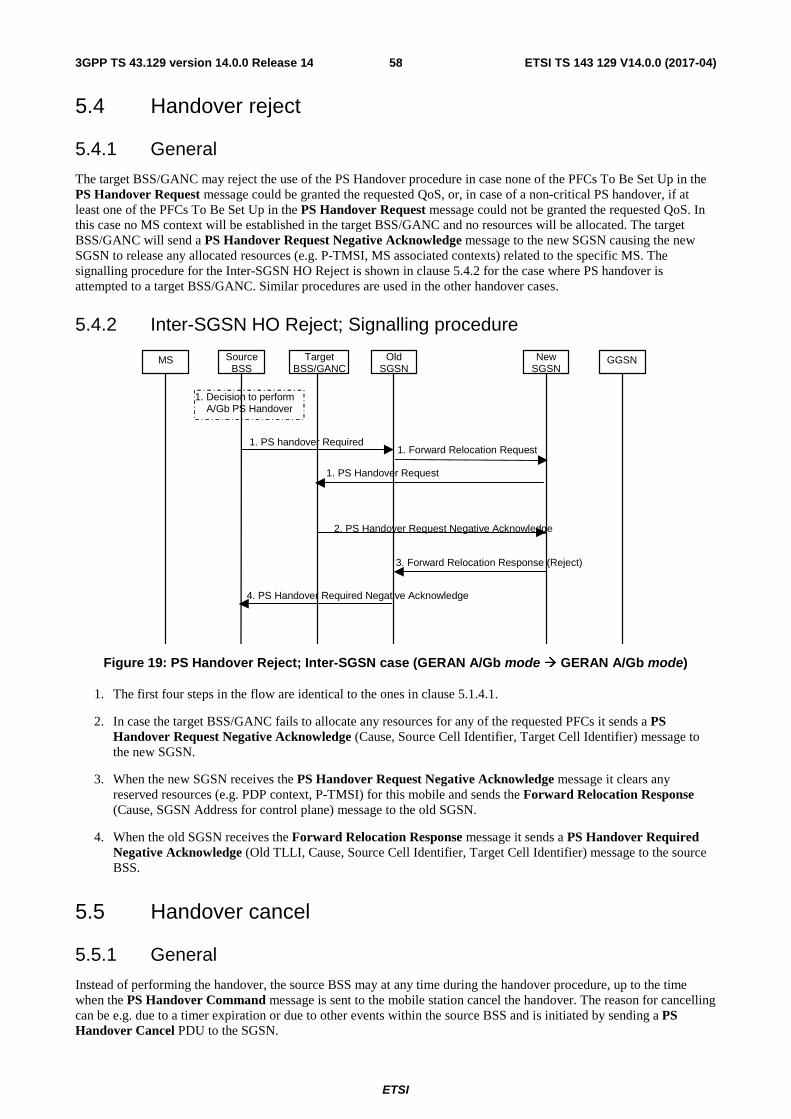
ETSI
ETSI TS 143 129 V14.0.0 (2017-04)583GPP TS 43.129 version 14.0.0 Release 14
5.4 Handover reject
5.4.1 General
The target BSS/GANC may reject the use of the PS Handover procedure in case none of the PFCs To Be Set Up in the PS Handover Request message could be granted the requested QoS, or, in case of a non-critical PS handover, if at least one of the PFCs To Be Set Up in the PS Handover Request message could not be granted the requested QoS. In this case no MS context will be established in the target BSS/GANC and no resources will be allocated. The target BSS/GANC will send a PS Handover Request Negative Acknowledge message to the new SGSN causing the new SGSN to release any allocated resources (e.g. P-TMSI, MS associated contexts) related to the specific MS. The signalling procedure for the Inter-SGSN HO Reject is shown in clause 5.4.2 for the case where PS handover is attempted to a target BSS/GANC. Similar procedures are used in the other handover cases.
5.4.2 Inter-SGSN HO Reject; Signalling procedure
MS Target BSS/GANC
Source BSS
Old SGSN
New SGSN
GGSN
1. Forward Rel ocation Request 1. PS Handover Request
1. PS handover Required
3. Forward Relocation Response (Reject)
2. PS Handover Request Negative Acknowledge
1. Decision to perform A/Gb PS Handover
4. PS Handover Required Negative Acknowledge
Figure 19: PS Handover Reject; Inter-SGSN case (GERAN A/Gb mode � GERAN A/Gb mode)
1. The first four steps in the flow are identical to the ones in clause 5.1.4.1.
2. In case the target BSS/GANC fails to allocate any resources for any of the requested PFCs it sends a PS Handover Request Negative Acknowledge (Cause, Source Cell Identifier, Target Cell Identifier) message to the new SGSN.
3. When the new SGSN receives the PS Handover Request Negative Acknowledge message it clears any reserved resources (e.g. PDP context, P-TMSI) for this mobile and sends the Forward Relocation Response (Cause, SGSN Address for control plane) message to the old SGSN.
4. When the old SGSN receives the Forward Relocation Response message it sends a PS Handover Required Negative Acknowledge (Old TLLI, Cause, Source Cell Identifier, Target Cell Identifier) message to the source BSS.
5.5 Handover cancel
5.5.1 General
Instead of performing the handover, the source BSS may at any time during the handover procedure, up to the time when the PS Handover Command message is sent to the mobile station cancel the handover. The reason for cancelling can be e.g. due to a timer expiration or due to other events within the source BSS and is initiated by sending a PS Handover Cancel PDU to the SGSN.
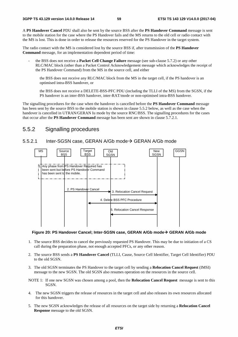
ETSI
ETSI TS 143 129 V14.0.0 (2017-04)593GPP TS 43.129 version 14.0.0 Release 14
A PS Handover Cancel PDU shall also be sent by the source BSS after the PS Handover Command message is sent to the mobile station for the case where the PS Handover fails and the MS returns to the old cell or radio contact with the MS is lost. This is done in order to release the resources reserved for the PS Handover in the target system.
The radio contact with the MS is considered lost by the source BSS if, after transmission of the PS Handover Command message, for an implementation dependent period of time:
- the BSS does not receive a Packet Cell Change Failure message (see sub-clause 5.7.2) or any other RLC/MAC block (other than a Packet Control Acknowledgement message which acknowledges the receipt of the PS Handover Command) from the MS in the source cell, and either
the BSS does not receive any RLC/MAC block from the MS in the target cell, if the PS handover is an optimised intra-BSS handover, or
the BSS does not receive a DELETE-BSS-PFC PDU (including the TLLI of the MS) from the SGSN, if the PS handover is an inter-BSS handover, inter-RAT/mode or non-optimised intra-BSS handover.
The signalling procedures for the case when the handover is cancelled before the PS Handover Command message has been sent by the source BSS to the mobile station is shown in clause 5.5.2 below, as well as the case when the handover is cancelled in UTRAN/GERAN Iu mode by the source RNC/BSS. The signalling procedures for the cases that occur after the PS Handover Command message has been sent are shown in clause 5.7.2.1.
5.5.2 Signalling procedures
5.5.2.1 Inter-SGSN case, GERAN A/Gb mode� GERAN A/Gb mode
Target BSS
Old SGSN
New SGSN
GGSN
3. Relocation Cancel Request
5. Relocation Cancel Response
2. PS Handover Cancel
4. Delete BSS PFC Procedure
1. Any phase from PS Handover Required has been sent but before PS Handover Command has been sent to the mobile.
Source BSS
MS
Figure 20: PS Handover Cancel; Inter-SGSN case, GERAN A/Gb mode� GERAN A/Gb mode
1. The source BSS decides to cancel the previously requested PS Handover. This may be due to initiation of a CS call during the preparation phase, not enough accepted PFCs, or any other reason.
2. The source BSS sends a PS Handover Cancel (TLLI, Cause, Source Cell Identifier, Target Cell Identifier) PDU to the old SGSN.
3. The old SGSN terminates the PS Handover to the target cell by sending a Relocation Cancel Request (IMSI) message to the new SGSN. The old SGSN also resumes operation on the resources in the source cell.
NOTE 1: If one new SGSN was chosen among a pool, then the Relocation Cancel Request message is sent to this SGSN.
4. The new SGSN triggers the release of resources in the target cell and also releases its own resources allocated for this handover.
5. The new SGSN acknowledges the release of all resources on the target side by returning a Relocation Cancel Response message to the old SGSN.
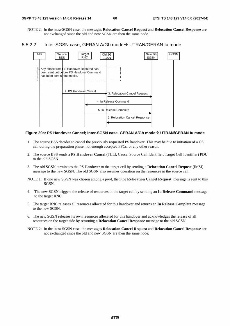
ETSI
ETSI TS 143 129 V14.0.0 (2017-04)603GPP TS 43.129 version 14.0.0 Release 14
NOTE 2: In the intra-SGSN case, the messages Relocation Cancel Request and Relocation Cancel Response are not exchanged since the old and new SGSN are then the same node.
5.5.2.2 Inter-SGSN case, GERAN A/Gb mode� UTRAN/GERAN Iu mode
Target RNC
Old 2G SGSN
New 3G SGSN
GGSN
3. Relocation Cancel Request
6. Relocation Cancel Response
2. PS Handover Cancel
4. Iu Release Command
1. Any phase from PS Handover Required has been sent but before PS Handover Command has been sent to the mobile.
Source BSS
MS
5. Iu Release Complete
Figure 20a: PS Handover Cancel; Inter-SGSN case, GERAN A/Gb mode� UTRAN/GERAN Iu mode
1. The source BSS decides to cancel the previously requested PS handover. This may be due to initiation of a CS call during the preparation phase, not enough accepted PFCs, or any other reason.
2. The source BSS sends a PS Handover Cancel (TLLI, Cause, Source Cell Identifier, Target Cell Identifier) PDU to the old SGSN.
3. The old SGSN terminates the PS Handover to the target cell by sending a Relocation Cancel Request (IMSI) message to the new SGSN. The old SGSN also resumes operation on the resources in the source cell.
NOTE 1: If one new SGSN was chosen among a pool, then the Relocation Cancel Request message is sent to this SGSN.
4. The new SGSN triggers the release of resources in the target cell by sending an Iu Release Command message to the target RNC
5. The target RNC releases all resources allocated for this handover and returns an Iu Release Complete message to the new SGSN.
6. The new SGSN releases its own resources allocated for this handover and acknowledges the release of all resources on the target side by returning a Relocation Cancel Response message to the old SGSN.
NOTE 2: In the intra-SGSN case, the messages Relocation Cancel Request and Relocation Cancel Response are not exchanged since the old and new SGSN are then the same node.
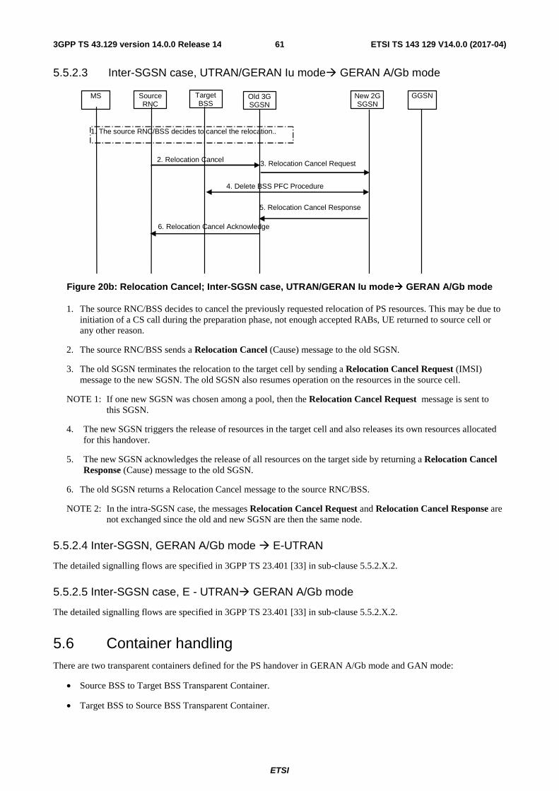
ETSI
ETSI TS 143 129 V14.0.0 (2017-04)613GPP TS 43.129 version 14.0.0 Release 14
5.5.2.3 Inter-SGSN case, UTRAN/GERAN Iu mode� GERAN A/Gb mode
Target BSS
Old 3G SGSN
New 2G SGSN
GGSN
3. Relocation Cancel Request
1. The source RNC/BSS decides to cancel the relocation..
Source RNC
MS
5. Relocation Cancel Response
2. Relocation Cancel
4. Delete BSS PFC Procedure
6. Relocation Cancel Acknowledge
Figure 20b: Relocation Cancel; Inter-SGSN case, UTRAN/GERAN Iu mode� GERAN A/Gb mode
1. The source RNC/BSS decides to cancel the previously requested relocation of PS resources. This may be due to initiation of a CS call during the preparation phase, not enough accepted RABs, UE returned to source cell or any other reason.
2. The source RNC/BSS sends a Relocation Cancel (Cause) message to the old SGSN.
3. The old SGSN terminates the relocation to the target cell by sending a Relocation Cancel Request (IMSI) message to the new SGSN. The old SGSN also resumes operation on the resources in the source cell.
NOTE 1: If one new SGSN was chosen among a pool, then the Relocation Cancel Request message is sent to this SGSN.
4. The new SGSN triggers the release of resources in the target cell and also releases its own resources allocated for this handover.
5. The new SGSN acknowledges the release of all resources on the target side by returning a Relocation Cancel Response (Cause) message to the old SGSN.
6. The old SGSN returns a Relocation Cancel message to the source RNC/BSS.
NOTE 2: In the intra-SGSN case, the messages Relocation Cancel Request and Relocation Cancel Response are not exchanged since the old and new SGSN are then the same node.
5.5.2.4 Inter-SGSN, GERAN A/Gb mode � E-UTRAN
The detailed signalling flows are specified in 3GPP TS 23.401 [33] in sub-clause 5.5.2.X.2.
5.5.2.5 Inter-SGSN case, E - UTRAN� GERAN A/Gb mode
The detailed signalling flows are specified in 3GPP TS 23.401 [33] in sub-clause 5.5.2.X.2.
5.6 Container handling There are two transparent containers defined for the PS handover in GERAN A/Gb mode and GAN mode:
• Source BSS to Target BSS Transparent Container.
• Target BSS to Source BSS Transparent Container.
ETSI
ETSI TS 143 129 V14.0.0 (2017-04)623GPP TS 43.129 version 14.0.0 Release 14
The Source BSS to Target BSS Transparent Container will carry the information to be transported transparently between the source BSS and the target BSS/GANC and between the source GANC and the target BSS related to PS handover.
The Target BSS to Source BSS Transparent Container will carry the information to be transported transparently between the target BSS and the source BSS/GANC and between the target GANC and the source BSS related to PS handover.
The generic handling of the source cell (GERAN A/Gb mode or UTRAN/GERAN Iu mode or E-UTRAN) to target cell (GERAN A/Gb mode or UTRAN/GERAN Iu mode or E-UTRAN) radio-related container is as follows:
• Created by the source BSS or RNC or eNB .
• Processed by the target BSS or RNC or eNB.
• Forwarded transparently by the SGSNs and MME .
The generic handling of the target cell (GERAN A/Gb mode or UTRAN/GERAN Iu mode or E-UTRAN ) to source cell (GERAN A/Gb mode or UTRAN/GERAN Iu mode or E-UTRAN) radio-related container is as follows:
• Created by the target BSS or RNC or eNB.
• Processed by the source BSS or RNC or eNB .
• Forwarded transparently by the SGSNs and MME .
The generic handling of the source cell to target cell radio-related container for PS handover from GERAN A/Gb mode to GAN mode or vice versa is as follows:
• Created by the source BSS or GANC.
• Processed by the target BSS for PS handover from a source GANC.
• Processed by the target GANC for PS handover from a source BSS.
• Forwarded transparently by the SGSNs.
The generic handling of the source cell to target cell radio-related container for PS handover from UTRAN to GAN mode or vice versa is as follows:
• Created by the source GANC or RNC.
• Processed by the target GANC for PS handover from a source RNC.
• Processed by the target RNC for PS handover from a source GANC.
• Forwarded transparently by the SGSNs.
The generic handling of the target cell to source cell radio-related container for PS handover from GERAN A/Gb mode to GAN mode or vice versa is as follows:
• Created by the target GANC or BSS.
• Processed by the source BSS for PS handover to a target GANC.
• Processed by the source GANC for PS handover to a target BSS.
• Forwarded transparently by the SGSNs.
The generic handling of the target cell to source cell radio-related container for PS handover from UTRAN to GAN mode or vice versa is as follows:
• Created by the target GANC or RNC.
• Processed by the source RNC for PS handover to a target GANC.
ETSI
ETSI TS 143 129 V14.0.0 (2017-04)633GPP TS 43.129 version 14.0.0 Release 14
• Processed by the source GANC for PS handover to a target RNC.
• Forwarded transparently by the SGSNs.
5.6.1 Contents of the containers
The transparent container will consist of two parts:
• The Radio Network part (RN part) carrying radio interface related parameters relevant for the MS and the radio network (BSS/RNC/eNB ) and sent transparently through the core network; This content is:
- Created by the source BSS/RNC/GANC/eNB and carried in the Source BSS to Target BSS / Source to Target transparent container (i.e. the forward container).
- Created by the target BSS/RNC/GANC/eNB and carried in the Target BSS to Source BSS / Target to Source transparent container (i.e. the reverse container).
- Processed by the target BSS/RNC/GANC/eNB (forward container only)
- Processed by the source BSS/RNC/GANC/eNB and MS (reverse container only).
• The Core Network part (CN part) carrying parameters relevant for the MS and the core network. This part is only needed from the new SGSN to send to the MS for PS handover to A/Gb mode and GAN mode and thus is only included in the Target BSS to Source BSS Transparent Container. This content is:
- Created by the new SGSN.
- Included in the Target BSS to Source BSS Transparent Container by the target BSS/GANC.
NOTE 1: The target BSS/GANC does not process the Core Network part.
- Forwarded transparently by the old SGSN and source BSS/RNC/GANC/eNB.
- Carried within the PS Handover Command message sent from the source BSS to the MS for PS handover from A/Gb mode to A/Gb mode or for PS handover from A/Gb mode to GAN mode.
- Carried within the PS Handover Command message included within a GA-PSR Handover Command message sent from the source GANC to the MS for PS handover from GAN mode to A/Gb mode.
- Carried within the PS Handover Command message included within a Handover from UTRAN Command message or the Handover from GERAN Iu Command message sent from the source RNC to the MS for PS handover from Iu mode to A/Gb mode.
- Carried within the PS Handover Command message included within a Handover from UTRAN Command message sent from the source RNC to the MS for PS handover from UTRAN to GAN mode.
- Carried within the PS Handover Command message included within a MobilityFromEUTRACommand message sent from the source eNB to the MS for PS handover from E-UTRAN to GERAN A/Gb mode.
- Processed by the MS.
The contents of the Radio Network part will depend on:
• Type of channels that are subject to PS handover, i.e. shared or dedicated.
NOTE 2: Currently dedicated channels are not considered in the PS handover in GERAN A/Gb mode.
• PS handover scenario, i.e. intra-mode or inter-RAT/mode.
• Whether it is sent in a forward container or a reverse container.
The contents of the Core Network part will depend on the PS handover scenario, i.e. intra-mode or inter-RAT/mode.
ETSI
ETSI TS 143 129 V14.0.0 (2017-04)643GPP TS 43.129 version 14.0.0 Release 14
5.6.1.1 Contents of the GERAN A/Gb mode or GAN mode → GERAN A/Gb mode Transparent Containers
5.6.1.1.1 Source BSS to Target BSS Transparent Container
In GERAN A/Gb mode/GAN mode -> GERAN A/Gb mode the Source BSS to Target BSS Transparent Container is sent in the PS Handover Required message, the Forward Relocation Request message and the PS Handover Request message.
The Radio Network part consists of the following:
• MS RAC.
• INTER RAT HANDOVER INFO (defined in 3GPP TS 25.331) containing the START_PS and UE RAC values, if available.
• E-UTRAN INTER RAT HANDOVER INFO (defined in 3GPP TS 48.018, see also 3GPP TS 36.331) if available
NOTE 1: The START_PS and UE RAC are needed to support PS Handover to UTRAN/GERAN Iu mode.
NOTE 2: The way of transferring START_PS and UE RAC from the mobile station to the BSS/GANC, is to piggyback the RRC container INTER RAT HANDOVER INFO, which includes START_PS and UE RAC, to the Attach Complete and Routing Area Update Complete messages from the mobile station to the SGSN. The SGSN will then include this container in every CREATE-BSS-PFC message sent to the BSS/GANC and/or in the PS Handover Complete Acknowledge message.
5.6.1.1.2 Target BSS to Source BSS Transparent Container
In GERAN A/Gb mode/GAN mode -> GERAN A/Gb mode the Target BSS to Source BSS Transparent Container is sent in the PS Handover Request Acknowledge message, Forward Relocation Response message and the PS Handover Required Acknowledge message.
The Radio Network part consists of the required information for access in the target cell and the information on allocated radio resources, uplink and downlink TBF parameters, Handover reference and generic parameters for access in the target cell (i.e. GPRS cell options, target cell "Cell Selection struct", global power control parameters, reference frequency lists, cell allocation, GPRS mobile allocation).
The Core Network part (i.e. NAS Container for PS HO) consists of the following parameters:
• an XID Command indicating Reset or 'Reset to old XID parameters' and the new IOV-UI for the target cell;
• the GPRS ciphering algorithm to be used in the target cell, if it is different from the ciphering algorithm used in the source cell.
5.6.1.2 Contents of the GERAN A/Gb mode or GAN mode → UTRAN Transparent Containers
5.6.1.2.1 Source to Target Transparent Container
In GERAN A/Gb mode/GAN mode -> UTRAN the Source to Target Transparent Container is encoded as the Source RNC to Target RNC Transaprent Container. It is sent from the source BSS/GANC to the target RNC in the PS Handover Required message and the Relocation Request message.
The Radio Network part consists of the following:
• RRC Container as defined in 3GPP TS 25.331 [17] will contain Inter RAT Handover Info (UTRAN specific information including START_PS/UE RAC) and Inter RAT UE radio access capability including MS RAC from BSS to RNC.
• Target Cell Id.
• Number of Iu instances IE. The value of this IE is set to 1 as defined in 3GPP TS 25.413 [23].
ETSI
ETSI TS 143 129 V14.0.0 (2017-04)653GPP TS 43.129 version 14.0.0 Release 14
• Relocation Type. The value of the IE is set to “UE involved”, as defined in 3GPP TS 25.413 [23].
5.6.1.2.2 Target to Source Transparent Container
In GERAN A/Gb mode/GAN mode -> UTRAN the Target to Source Transparent Container is encoded as the Target RNC to Source RNC Transparent Container. Itis sent from the target RNC to the source BSS/GANC in the Relocation Request Acknowledge message, Forward Relocation Response message and the PS Handover Required Acknowledge message.
The Radio Network part consists of the RRC message, i.e. the Handover to UTRAN Command message (as defined in 3GPP TS 25.331 [17]) used to perform handover from GERAN A/Gb mode/GAN mode to UTRAN. This message will be sent to the MS/UE within the PS Handover Command message (for PS handover from GERAN A/Gb mode) or within the GA-PSR Handover Command message (for PS handover from GAN mode).
5.6.1.3 Contents of the UTRAN → GERAN A/Gb Mode or GAN mode Transparent Containers
5.6.1.3.1 Source BSS to Target BSS Transparent Container
In UTRAN -> GERAN A/Gb mode/GAN mode the Source BSS to Target BSS Transparent Container is sent from the source RNC to the target BSS/GANC in the Relocation Required, Forward Relocation Request message and the PS Handover Request message in order to support inter-RAT PS handover from UTRAN (CELL_DCH state or CELL_FACH state, only PS RABs established) to GERAN A/Gb mode/GAN mode.
The Radio Network part consists of the following information:
• MS RAC.
• INTER RAT HANDOVER INFO (defined in 3GPP TS 25.331) containing the START_PS and UE RAC values.
• E-UTRAN INTER RAT HANDOVER INFO (defined in 3GPP TS 48.018, see also 3GPP TS 36.331) if available
NOTE: The START_PS value received in the INTER RAT HANDOVER INFO is not always aligned with the START_PS value stored in the MS after it has attached to the GSM network. The target BSS shall replace the value received in the container received from the source RNC with the value received from the MS via the SGSN (i.e. within a CREATE-BSS-PFC message or a PS Handover Complete Acknowledge message).
5.6.1.3.2 Target BSS to Source BSS Transparent Container
In UTRAN -> GERAN A/Gb mode/GAN mode the Target BSS to Source BSS Transparent Container is sent from the target BSS/GANC to the source RNC in the PS Handover Request Acknowledge message, Forward Relocation Response message and the Relocation Command message in order to support inter-RAT PS handover from UTRAN (CELL_DCH state or CELL_FACH state, only PS RABs established) to GERAN A/Gb mode/GAN mode.
For PS handover from UTRAN to GERAN A/Gb mode the Radio Network part consist of the required information for access in the target cell and the information on allocated radio resources: uplink and downlink TBF parameters, PS Handover reference and generic parameters for access in the target cell (i.e. GPRS cell options, target cell "Cell Selection struct", global power control parameters, reference frequency lists, cell allocation, GPRS mobile allocation). Over the air interface this radio network container is sent within the Handover from UTRAN Command message.
For PS handover from UTRAN to GAN mode the Radio Network part consists only of the mandatory fields within the PS Handover Radio Resources IE carried within the PS Handover Command message.
The Core Network part (i.e. NAS Container for PS HO) consist of the following parameters:
• an XID Command indicating Reset or 'Reset to old XID parameters' and the new IOV-UI for the target cell;
• the GPRS ciphering algorithm to be used in the target cell;
ETSI
ETSI TS 143 129 V14.0.0 (2017-04)663GPP TS 43.129 version 14.0.0 Release 14
5.6.1.4 Contents of the GERAN A/Gb mode → GERAN Iu mode Transparent Containers
5.6.1.4.1 Source to Target Transparent Container
In GERAN A/Gb mode -> GERAN Iu mode the Source to Target Transparent Container is encoded as the Source RNC to Target RNC Transparent Container. It is is sent from the source BSS to the target BSS (Iu) in the PS Handover Required message, Forward Relocation Request message and the Relocation Request message.
The Radio Network part consists of:
• RRC Container as defined in 3GPP TS 44.118 [16] shall contain START_PS /MS GERAN IU capabilities.
• Target Cell Id.
• Number of Iu instances. The value of the IE is set to 1 as defined in 3GPP TS 25.413 [23].
• Relocation Type. The value of the IE is set to “UE involved”, as defined in 3GPP TS 25.413 [23].
5.6.1.4.2 Target to Source Transparent Container
In GERAN A/Gb mode -> GERAN Iu mode the Target to Source Transparent Container is encoded as the Target RNC to Source RNC Transparent Conatiner. It is sent from the target BSS (Iu) to source BSS in the Relocation Request Acknowledge message, Forward Relocation Response message and the PS Handover Required Acknowledge message.
The Radio Network Part consist of the RRC message used in GERAN Iu mode to perform handover, i.e. Radio Bearer Reconfiguration message as defined in 3GPP TS 44.118 [16]. This message will be sent to the MS in the PS Handover Command message.
5.6.1.5 Content of GERAN Iu mode → GERAN A/Gb mode Transparent Containers
5.6.1.5.1 Source BSS to Target BSS Transparent Container
In GERAN Iu mode -> GERAN A/Gb mode the Source BSS to Target BSS Transparent Container is sent from the source BSS (Iu) to the target BSS in the Relocation Required message, Forward Relocation Request message and the PS Handover Request message.
The Radio Network part consists of the following:
• MS RAC.
• INTER RAT OR MODE HANDOVER INFO with MS capabilities as defined in 3GPP TS 44.118 [16].
NOTE: START_PS and UE RAC shall be added to this IE.
5.6.1.5.2 Target BSS to Source BSS Transparent Container
In GERAN Iu mode -> GERAN A/Gb mode the Target BSS to Source BSS Transparent Container is sent from the target BSS to the source BSS (Iu) in the PS Handover Request Acknowledge message, Forward Relocation Response message and the Relocation Command message in order to support PS handover to GERAN A/Gb mode from GERAN Iu mode (RRC Cell_Dedicated state or RRC CELL_Shared state, only PS RABs established).
The Radio Network part consists of the required information for access in the target cell and the information on allocated radio resources: Uplink and downlink TBF parameters, PS Handover reference and generic parameters for access in the target cell (i.e. GPRS cell options, target cell "Cell Selection struct", global power control parameters, reference frequency lists, cell allocation, GPRS mobile allocation). Over the air interface this information is sent in the Handover from GERAN Iu mode Command message.
The Core Network (i.e. NAS Container for PS HO) part consists of the following parameters:
• an XID Command indicating Reset or 'Reset to old XID parameters' and the new IOV-UI for the target cell;
ETSI
ETSI TS 143 129 V14.0.0 (2017-04)673GPP TS 43.129 version 14.0.0 Release 14
• the GPRS ciphering algorithm to be used in the target cell
5.6.1.6 Contents of the GERAN A/Gb mode → GAN mode Transparent Containers
5.6.1.6.1 Source BSS to Target BSS Transparent Container
In GERAN A/Gb mode -> GAN mode the Source BSS to Target BSS Transparent Container is sent in the PS Handover Required message, the Forward Relocation Request message and the PS Handover Request message.
The Radio Network part consists of the following:
• MS RAC.
• START_PS and UE RAC (for dual mode mobile stations).
NOTE 1: The START_PS and UE RAC are needed to support PS Handover to UTRAN/GERAN Iu mode.
NOTE 2: The way of transferring START_PS and UE RAC from the mobile station to the BSC, is to piggyback the RRC container INTER RAT HANDOVER INFO, which includes START_PS and UE RAC, to the Attach Complete and Routing Area Update Complete messages from the mobile station to the SGSN. The SGSN will then include this container in every CREATE-BSS-PFC message sent to the BSC.
5.6.1.6.2 Target BSS to Source BSS Transparent Container
In GERAN A/Gb mode -> GAN mode the Target BSS to Source BSS Transparent Container is sent in the PS Handover Request Acknowledge message, Forward Relocation Response message and the PS Handover Required Acknowledge message.
The Radio Network part consists only of the mandatory fields within the PS Handover Radio Resources IE carried within the PS Handover Command message.
The Core Network part (i.e. NAS Container for PS HO) consists of the following parameters:
• an XID Command indicating Reset or 'Reset to old XID parameters' and the new IOV-UI for the target cell;
• the GPRS ciphering algorithm to be used in the target cell, if it is different from the ciphering algorithm used in the source cell.
5.6.1.7 Contents of the GERAN A/Gb mode → E-UTRAN Transparent Containers
5.6.1.7.1 Source to Target Transparent Container
In GERAN A/Gb mode to E-UTRAN handover the Source to Target Transparent Container is encoded as the Source eNB to Target eNB Transparent Container. It is sent from the Source BSS to the target eNB in the PS Handover Required message, the Forward Relocation Request message and the Handover Request message.
The Radio Network part consists of:
- MS RAC
- INTER RAT HANDOVER INFO (defined in 3GPP TS 25.331) containing the START_PS and UE RAC values, if available
- Target Cell Id.
5.6.1.7.2 Target to Source Transparent Container
In GERAN A/Gb mode to E-UTRAN handover the Target to Source Transparent Conatiner is encoded as the Target eNB to Source eNB Transparent Container. It is sent from the target eNB to source BSS in the Handover Request Acknowledge message, the Forward Relocation Response message and the PS Handover Required Acknowledge message.
ETSI
ETSI TS 143 129 V14.0.0 (2017-04)683GPP TS 43.129 version 14.0.0 Release 14
The Radio Network Part consists of the RRC message used in E-UTRAN to perform handover, i.e. (RRC E-UTRA) HandoverCommand message contains the entire DL-DCCH-Message including the RRCConnectionReconfiguration message as defined in 3GPP TS 36.331 [31]. This message will be sent to the MS in the PS Handover Command message.
5.6.1.8 Contents of the E-UTRAN → GERAN A/Gb mode Transparent Containers
5.6.1.8.1 Source BSS to Target BSS Transparent Container
In E-UTRAN to GERAN A/Gb mode handover the Source BSS to Target BSS Transparent Container is sent from the Source eNB to the Target BSS in the Handover Required message, the Forward Relocation Request message and the PS Handover Request message
The Radio Network part consists of the following information:
- MS RAC IE.
- INTER RAT HANDOVER INFO (defined in 3GPP TS 25.331) containing the START_PS and UE RAC values, if available.
- E-UTRAN INTER RAT HANDOVER INFO (defined in 3GPP TS 48.018, see also 3GPP TS 36.331).
5.6.1.8.2 Target BSS to Source BSS Transparent Container
In E-UTRAN to GERAN A/Gb mode handover the Target BSS to Source BSS Transparent Container is sent from the Target BSS to the Source eNB in the PS Handover Request Acknowledge message, the Forward Relocation Response message and the Handover Command message.
For PS handover from E-UTRAN to GERAN A/Gb mode the Radio Network part consist of the required information for access in the target cell and the information on allocated radio resources: uplink and downlink TBF parameters, PS Handover reference and generic parameters for access in the target cell (i.e. GPRS cell options, target cell "Cell Selection struct", global power control parameters, reference frequency lists, cell allocation, GPRS mobile allocation). Over the air interface this radio network container is sent within the MobilityFromEUTRACommand message.
The Core Network part (i.e. NAS Container for PS HO) consists of the following parameters:
- an XID Command indicating Reset or 'Reset to old XID parameters' and the new IOV-UI for the target cell;
- the GPRS ciphering algorithm to be used in the target cell.
5.7 PS Handover Failure During the PS handover procedure several types of failures can be identified. The PS handover failures may be typical network and signalling failure occurrences such as failures related to the loss of signalling messages, incorrect information element in the signalling messages or failures due to network nodes failures or specific to abnormal cases occurring during PS handover procedures.
In general the PS handover failures can be divided into:
• Preparation Phase Failure Scenarios on the Um, Gb, Gn and Up interface.
• Execution Phase Failure Scenarios on the Um, Gb and Gn interface.
NOTE: RAU procedure failures will be handled as specified in 3GPP TS 24.008 [15].
A list of appropriate cause values should be chosen/defined to indicate to the source cell and target cell nodes the cause of the PS Handover Request Negative Acknowledge and the PS handover Cancel messages.
ETSI
ETSI TS 143 129 V14.0.0 (2017-04)693GPP TS 43.129 version 14.0.0 Release 14
5.7.1 Preparations Phase Failure Scenarios
5.7.1.1 PS Handover preparation phase failure scenarios on the Um interface
• No Resource Reservation / Allocation:
- No radio resources available in the target cell.
5.7.1.2 PS Handover preparation phase failure scenarios on the Gb interface
• No Resource Reservation / Allocation on the target system:
- No radio resources available in the target cell (see clause 5.4). Appropriate cause values are needed in the PS Handover Request Negative Acknowledge message.
• Insufficient resource allocation by the target system:
- In case of insufficient resource allocation by the target side the source BSS may cancel the PS handover procedure (see clause 5.5).
• Feature "PS Handover" not supported:
- A new cause value is needed for the Gb interface if the target BSS/GANC does not support the PS Handover procedure.
• •Target CSG cell is not allowed for this MS:
- A new cause value is needed for the Gb interface to inform the source BSS that the target CSG cell is invalid whenever access control performed according to the CSG Subscription List is unsuccessful.
• Generic Causes:
- Generic causes for the Gb interface failures are defined in 3GPP TS 48.018 [10]. The same cause values are applicable to the PS handover procedure on the Gb interface.
5.7.1.3 PS Handover preparation phase failure scenarios on the Gn interface
• Context Transfer Failure:
- Context transfer failure may occur due to various causes defined in 3GPP TS 29.060 [11]. These cause values will be utilized during PS handover procedure. These values are to be utilized during PS handover procedure to indicate to the old SGSN the cause of the PS handover reject. Consequently an appropriate cause value should be chosen to allow the old SGSN to indicate to the source BSS the cause of failure.
• No Resource Reservation/ No Resource Allocation:
- Resource Reservation/Allocation failure occurs when no radio resources are available in the target cell. Consequently an appropriate cause value should be chosen to allow the old SGSN to indicate to the source BSS the cause of failure.
• Procedure "PS Handover" not supported:
- This occurs when the new SGSN does not support the PS Handover feature.
• Generic Causes:
- In 3GPP TS 29.060 [11] a set of cause values are defined. The same cause values are applicable to the PS handover procedure on the Gn interface.
5.7.1.4 PS Handover preparation phase failure scenarios on the Up interface
• Failure to allocate a GA-PSR Transport Channel
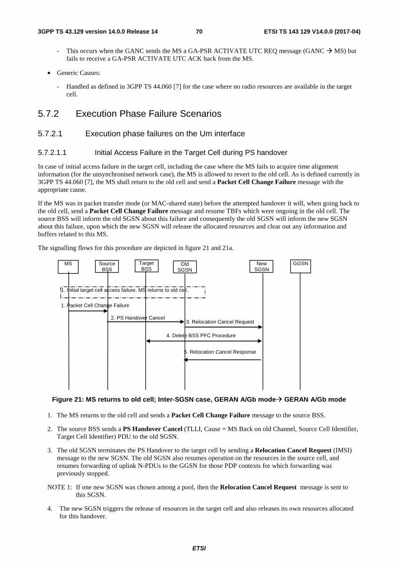
ETSI
ETSI TS 143 129 V14.0.0 (2017-04)703GPP TS 43.129 version 14.0.0 Release 14
- This occurs when the GANC sends the MS a GA-PSR ACTIVATE UTC REQ message (GANC � MS) but fails to receive a GA-PSR ACTIVATE UTC ACK back from the MS.
• Generic Causes:
- Handled as defined in 3GPP TS 44.060 [7] for the case where no radio resources are available in the target cell.
5.7.2 Execution Phase Failure Scenarios
5.7.2.1 Execution phase failures on the Um interface
5.7.2.1.1 Initial Access Failure in the Target Cell during PS handover
In case of initial access failure in the target cell, including the case where the MS fails to acquire time alignment information (for the unsynchronised network case), the MS is allowed to revert to the old cell. As is defined currently in 3GPP TS 44.060 [7], the MS shall return to the old cell and send a Packet Cell Change Failure message with the appropriate cause.
If the MS was in packet transfer mode (or MAC-shared state) before the attempted handover it will, when going back to the old cell, send a Packet Cell Change Failure message and resume TBFs which were ongoing in the old cell. The source BSS will inform the old SGSN about this failure and consequently the old SGSN will inform the new SGSN about this failure, upon which the new SGSN will release the allocated resources and clear out any information and buffers related to this MS.
The signalling flows for this procedure are depicted in figure 21 and 21a.
Target BSS
Old SGSN
New SGSN
GGSN
3. Relocation Cancel Request
5. Relocation Cancel Response
2. PS Handover Cancel
4. Delete BSS PFC Procedure
1. Initial target cell access failure. MS returns to old cell.
Source BSS
MS
1. Packet Cell Change Failure
Figure 21: MS returns to old cell; Inter-SGSN case, GERAN A/Gb mode� GERAN A/Gb mode
1. The MS returns to the old cell and sends a Packet Cell Change Failure message to the source BSS.
2. The source BSS sends a PS Handover Cancel (TLLI, Cause = MS Back on old Channel, Source Cell Identifier, Target Cell Identifier) PDU to the old SGSN.
3. The old SGSN terminates the PS Handover to the target cell by sending a Relocation Cancel Request (IMSI) message to the new SGSN. The old SGSN also resumes operation on the resources in the source cell, and resumes forwarding of uplink N-PDUs to the GGSN for those PDP contexts for which forwarding was previously stopped.
NOTE 1: If one new SGSN was chosen among a pool, then the Relocation Cancel Request message is sent to this SGSN.
4. The new SGSN triggers the release of resources in the target cell and also releases its own resources allocated for this handover.
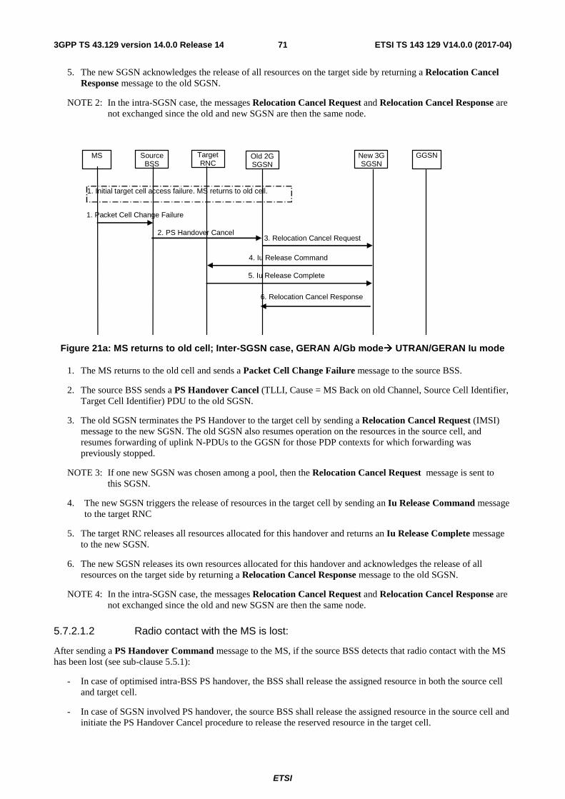
ETSI
ETSI TS 143 129 V14.0.0 (2017-04)713GPP TS 43.129 version 14.0.0 Release 14
5. The new SGSN acknowledges the release of all resources on the target side by returning a Relocation Cancel Response message to the old SGSN.
NOTE 2: In the intra-SGSN case, the messages Relocation Cancel Request and Relocation Cancel Response are not exchanged since the old and new SGSN are then the same node.
Target RNC
Old 2G SGSN
New 3G SGSN
GGSN
3. Relocation Cancel Request
6. Relocation Cancel Response
2. PS Handover Cancel
1. Initial target cell access failure. MS returns to old cell.
Source BSS
MS
1. Packet Cell Change Failure
4. Iu Release Command
5. Iu Release Complete
Figure 21a: MS returns to old cell; Inter-SGSN case, GERAN A/Gb mode� UTRAN/GERAN Iu mode
1. The MS returns to the old cell and sends a Packet Cell Change Failure message to the source BSS.
2. The source BSS sends a PS Handover Cancel (TLLI, Cause = MS Back on old Channel, Source Cell Identifier, Target Cell Identifier) PDU to the old SGSN.
3. The old SGSN terminates the PS Handover to the target cell by sending a Relocation Cancel Request (IMSI) message to the new SGSN. The old SGSN also resumes operation on the resources in the source cell, and resumes forwarding of uplink N-PDUs to the GGSN for those PDP contexts for which forwarding was previously stopped.
NOTE 3: If one new SGSN was chosen among a pool, then the Relocation Cancel Request message is sent to this SGSN.
4. The new SGSN triggers the release of resources in the target cell by sending an Iu Release Command message to the target RNC
5. The target RNC releases all resources allocated for this handover and returns an Iu Release Complete message to the new SGSN.
6. The new SGSN releases its own resources allocated for this handover and acknowledges the release of all resources on the target side by returning a Relocation Cancel Response message to the old SGSN.
NOTE 4: In the intra-SGSN case, the messages Relocation Cancel Request and Relocation Cancel Response are not exchanged since the old and new SGSN are then the same node.
5.7.2.1.2 Radio contact with the MS is lost:
After sending a PS Handover Command message to the MS, if the source BSS detects that radio contact with the MS has been lost (see sub-clause 5.5.1):
- In case of optimised intra-BSS PS handover, the BSS shall release the assigned resource in both the source cell and target cell.
- In case of SGSN involved PS handover, the source BSS shall release the assigned resource in the source cell and initiate the PS Handover Cancel procedure to release the reserved resource in the target cell.
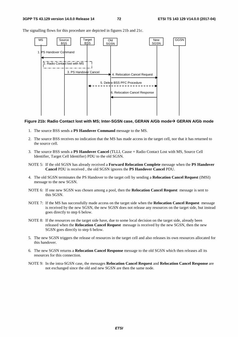
ETSI
ETSI TS 143 129 V14.0.0 (2017-04)723GPP TS 43.129 version 14.0.0 Release 14
The signalling flows for this procedure are depicted in figures 21b and 21c.
Target BSS
Old SGSN
New SGSN
GGSN
4. Relocation Cancel Request
6. Relocation Cancel Response
3. PS Handover Cancel
5. Delete BSS PFC Procedure
2. Radio Contact lost with MS
Source BSS
MS
1. PS Handover Command
Figure 21b: Radio Contact lost with MS; Inter-SGSN case, GERAN A/Gb mode� GERAN A/Gb mode
1. The source BSS sends a PS Handover Command message to the MS.
2. The source BSS receives no indication that the MS has made access in the target cell, nor that it has returned to the source cell.
3. The source BSS sends a PS Handover Cancel (TLLI, Cause = Radio Contact Lost with MS, Source Cell Identifier, Target Cell Identifier) PDU to the old SGSN.
NOTE 5: If the old SGSN has already received a Forward Relocation Complete message when the PS Handover Cancel PDU is received , the old SGSN ignores the PS Handover Cancel PDU.
4. The old SGSN terminates the PS Handover to the target cell by sending a Relocation Cancel Request (IMSI) message to the new SGSN.
NOTE 6: If one new SGSN was chosen among a pool, then the Relocation Cancel Request message is sent to this SGSN.
NOTE 7: If the MS has successfully made access on the target side when the Relocation Cancel Request message is received by the new SGSN, the new SGSN does not release any resources on the target side, but instead goes directly to step 6 below.
NOTE 8: If the resources on the target side have, due to some local decision on the target side, already been released when the Relocation Cancel Request message is received by the new SGSN, then the new SGSN goes directly to step 6 below.
5. The new SGSN triggers the release of resources in the target cell and also releases its own resources allocated for this handover.
6. The new SGSN returns a Relocation Cancel Response message to the old SGSN which then releases all its resources for this connection.
NOTE 9: In the intra-SGSN case, the messages Relocation Cancel Request and Relocation Cancel Response are not exchanged since the old and new SGSN are then the same node.
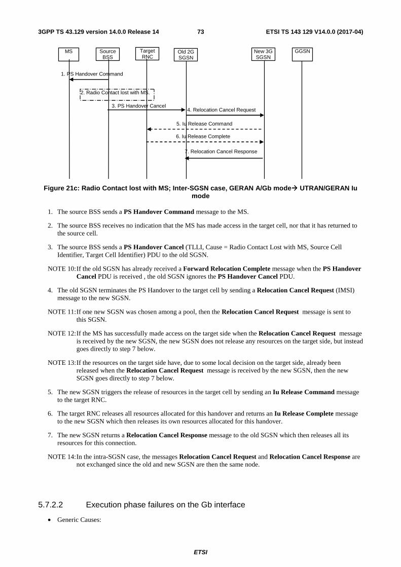
ETSI
ETSI TS 143 129 V14.0.0 (2017-04)733GPP TS 43.129 version 14.0.0 Release 14
Target RNC
Old 2G SGSN
New 3G SGSN
GGSN
4. Relocation Cancel Request
7. Relocation Cancel Response
3. PS Handover Cancel
2. Radio Contact lost with MS.
Source BSS
MS
5. Iu Release Command
6. Iu Release Complete
1. PS Handover Command
Figure 21c: Radio Contact lost with MS; Inter-SGSN case, GERAN A/Gb mode� UTRAN/GERAN Iu mode
1. The source BSS sends a PS Handover Command message to the MS.
2. The source BSS receives no indication that the MS has made access in the target cell, nor that it has returned to the source cell.
3. The source BSS sends a PS Handover Cancel (TLLI, Cause = Radio Contact Lost with MS, Source Cell Identifier, Target Cell Identifier) PDU to the old SGSN.
NOTE 10: If the old SGSN has already received a Forward Relocation Complete message when the PS Handover Cancel PDU is received , the old SGSN ignores the PS Handover Cancel PDU.
4. The old SGSN terminates the PS Handover to the target cell by sending a Relocation Cancel Request (IMSI) message to the new SGSN.
NOTE 11: If one new SGSN was chosen among a pool, then the Relocation Cancel Request message is sent to this SGSN.
NOTE 12: If the MS has successfully made access on the target side when the Relocation Cancel Request message is received by the new SGSN, the new SGSN does not release any resources on the target side, but instead goes directly to step 7 below.
NOTE 13: If the resources on the target side have, due to some local decision on the target side, already been released when the Relocation Cancel Request message is received by the new SGSN, then the new SGSN goes directly to step 7 below.
5. The new SGSN triggers the release of resources in the target cell by sending an Iu Release Command message to the target RNC.
6. The target RNC releases all resources allocated for this handover and returns an Iu Release Complete message to the new SGSN which then releases its own resources allocated for this handover.
7. The new SGSN returns a Relocation Cancel Response message to the old SGSN which then releases all its resources for this connection.
NOTE 14: In the intra-SGSN case, the messages Relocation Cancel Request and Relocation Cancel Response are not exchanged since the old and new SGSN are then the same node.
5.7.2.2 Execution phase failures on the Gb interface
• Generic Causes:
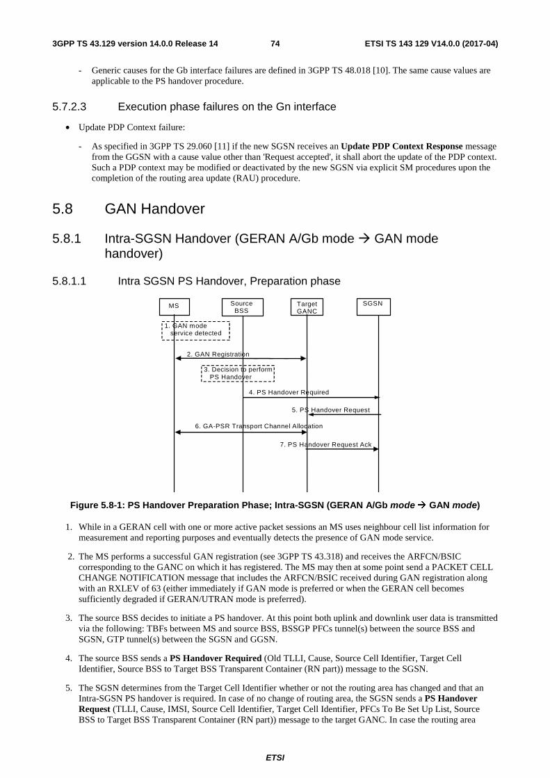
ETSI
ETSI TS 143 129 V14.0.0 (2017-04)743GPP TS 43.129 version 14.0.0 Release 14
- Generic causes for the Gb interface failures are defined in 3GPP TS 48.018 [10]. The same cause values are applicable to the PS handover procedure.
5.7.2.3 Execution phase failures on the Gn interface
• Update PDP Context failure:
- As specified in 3GPP TS 29.060 [11] if the new SGSN receives an Update PDP Context Response message from the GGSN with a cause value other than 'Request accepted', it shall abort the update of the PDP context. Such a PDP context may be modified or deactivated by the new SGSN via explicit SM procedures upon the completion of the routing area update (RAU) procedure.
5.8 GAN Handover
5.8.1 Intra-SGSN Handover (GERAN A/Gb mode � GAN mode handover)
5.8.1.1 Intra SGSN PS Handover, Preparation phase
MS Target GANC
Source BSS
SGSN
1. GAN mode service detected
2. GAN Registration
4. PS Handover Required
5. PS Handover Request
7. PS Handover Request Ack
6. GA-PSR Transport Channel Allocation
3. Decision to perform PS Handover
Figure 5.8-1: PS Handover Preparation Phase; Intra-SGSN (GERAN A/Gb mode � GAN mode)
1. While in a GERAN cell with one or more active packet sessions an MS uses neighbour cell list information for measurement and reporting purposes and eventually detects the presence of GAN mode service.
2. The MS performs a successful GAN registration (see 3GPP TS 43.318) and receives the ARFCN/BSIC corresponding to the GANC on which it has registered. The MS may then at some point send a PACKET CELL CHANGE NOTIFICATION message that includes the ARFCN/BSIC received during GAN registration along with an RXLEV of 63 (either immediately if GAN mode is preferred or when the GERAN cell becomes sufficiently degraded if GERAN/UTRAN mode is preferred).
3. The source BSS decides to initiate a PS handover. At this point both uplink and downlink user data is transmitted via the following: TBFs between MS and source BSS, BSSGP PFCs tunnel(s) between the source BSS and SGSN, GTP tunnel(s) between the SGSN and GGSN.
4. The source BSS sends a PS Handover Required (Old TLLI, Cause, Source Cell Identifier, Target Cell Identifier, Source BSS to Target BSS Transparent Container (RN part)) message to the SGSN.
5. The SGSN determines from the Target Cell Identifier whether or not the routing area has changed and that an Intra-SGSN PS handover is required. In case of no change of routing area, the SGSN sends a PS Handover Request (TLLI, Cause, IMSI, Source Cell Identifier, Target Cell Identifier, PFCs To Be Set Up List, Source BSS to Target BSS Transparent Container (RN part)) message to the target GANC. In case the routing area
ETSI
ETSI TS 143 129 V14.0.0 (2017-04)753GPP TS 43.129 version 14.0.0 Release 14
changes, the SGSN shall assign a new P-TMSI for the MS and derive a local TLLI prior to the sending of the PS Handover Request message. All PFCs shall be included in this message regardless of whether or not they are active.
NOTE 1: The BSS PFCs required to be set up are downloaded to the target GANC from the SGSN, i.e. all information required for PFC creation.
6. Based upon the ABQP for each PFC the target GANC makes a decision about whether or not to activate a GA-PSR Transport Channel. If a GA-PSR Transport Channel is allocated it is used to support the packet data flow requirements of all requested PFCs. The details of this decision are implementation specific but could take into account the current GAN cell loading and the ABQP indicated for each requested PFC. The target GANC allocates a GA-PSR Transport Channel as described in 3GPP TS 43.318. After allocating the GA-PSR Transport Channel the target GANC shall prepare the Target BSS to Source BSS Transparent Container for the set up BSS PFCs.
7. The target GANC sends the PS Handover Request Acknowledge (TLLI, List of Set Up PFCs, Target BSS to Source BSS Transparent Container (RN part)) message to the SGSN. Upon sending the PS Handover Request Acknowledge message the target GANC shall be prepared to receive downlink LLC PDUs from the SGSN for all requested PFCs (i.e. the List of Set Up PFCs in this message shall always match the PFCs To Be Set Up List included in the corresponding PS Handover Request message since a GA-PSR Transport Channel is allocated with the intent of supporting all PFCs requested by the SGSN).
When the SGSN receives the PS Handover Request Acknowledge message and it decides to proceed with the handover, the preparation phase is finished and the execution phase will follow.
5.8.1.2 Intra SGSN PS Handover, Execution phase
The execution phase is the same as described for Intra SGSN, GERAN A/Gb mode to GERAN A/Gb mode PS handover except for the following:
• The BSS sends the PS Handover Command message where the RN part does not include any of the optional information.
• After receiving the PS Handover Command message in the source cell the MS determines that the indicated ARFCN and BSIC match those of the GAN cell that it last registered on and therefore does not perform system synchronization in the GAN cell. Instead, the MS enables the transmission of uplink LLC PDUs on the allocated GA-PSR Transport Channel and sends a GA-PSR HANDOVER COMPLETE message to the target GANC. Note that the reception of downlink LLC PDUs is enabled in the MS upon allocation of the GA-PSR Transport Channel during the preparation phase.
• Upon reception of the GA-PSR HANDOVER COMPLETE message from the MS in the GAN cell the target GANC sends a PS Handover Complete (TLLI, IMSI, Target Cell Identifier) message to the SGSN.
5.8.2 Intra-SGSN Handover (GAN mode � GERAN A/Gb mode handover)
5.8.2.1 Intra SGSN PS Handover, Preparation phase
The preparation phase is the same as described for Intra SGSN, GERAN A/Gb mode to GERAN A/Gb mode PS handover except for the following:
• While in a GAN cell an MS sends the GA-PSR HANDOVER INFORMATION message to the GANC indicating a list of target GERAN A/Gb mode cells, identified by CGI, in order of preference for PS handover, and includes the received signal strength for each identified GERAN A/Gb mode cell. The MS decision to send the GA-PSR HANDOVER INFORMATION may be based on local measurements in the MS (see 3GPP TS 44.318 [28]). This list is the most recent information available from the GSM RR subsystem. In addition, the GA-PSR HANDOVER INFORMATION message may include a list of target UTRAN cells ranked in order of preference for PS handover, and the received signal strength for each identified UTRAN cell.
• The source GANC selects a target GERAN A/Gb mode cell and triggers the PS handover preparation phase by signalling to the SGSN the need for PS handover (i.e. it sends the PS Handover Required message) and including the target GERAN A/Gb mode cell.
ETSI
ETSI TS 143 129 V14.0.0 (2017-04)763GPP TS 43.129 version 14.0.0 Release 14
• When the source GANC decides to trigger a PS handover both uplink and downlink user data is transmitted via the GA-PSR Transport Channel between MS and source GANC, BSSGP PFCs tunnel(s) between the source GANC and SGSN, and GTP tunnel(s) between the SGSN and GGSN.
5.8.2.2 Intra SGSN PS Handover, Execution phase
The execution phase is the same as described for Intra SGSN, GERAN A/Gb mode to GERAN A/Gb mode PS handover except for the following:
• The SGSN sends a PS Handover Required Acknowledge (Old TLLI, List of Set Up PFCs, Target BSS to Source BSS Transparent Container (RN part)) message to the source GANC.
• Before sending the GA-PSR HANDOVER COMMAND message to the MS the source GANC, based on QoS, may try to empty the downlink GANC buffer for one or more PFCs.
• The source GANC interrupts the downlink transmission of LLC PDUs on the GA-PSR Transport Channel and sends the MS a GA-PSR HANDOVER COMMAND message that includes a PS Handover Command (RN part only) created by the target BSS.
5.8.3 Inter-SGSN Handover (GERAN A/Gb mode � GAN mode handover)
5.8.3.1 Inter SGSN PS Handover, Preparation phase
The preparation phase is the same as described for Intra SGSN, GERAN A/Gb mode to GAN mode PS handover except that Inter-SGSN communications are required and are as described for Inter-SGSN A/Gb mode to A/Gb mode PS handover.
5.8.3.2 Inter SGSN PS Handover, Execution phase
The execution phase is the same as described for the Intra SGSN PS Handover, Execution phase in sub-clause 5.8.1.2.
5.8.4 Inter-SGSN Handover (GAN mode � GERAN A/Gb mode handover)
5.8.4.1 Inter SGSN PS Handover, Preparation phase
The preparation phase is the same as described for Inter SGSN, GERAN A/Gb mode to GERAN A/Gb mode PS handover except for the following:
• While in a GAN cell an MS sends the GA-PSR HANDOVER INFORMATION message to the GANC indicating a list of target GERAN A/Gb mode cells, identified by CGI, in order of preference for PS handover, and includes the received signal strength for each identified GERAN A/Gb mode cell. The MS decision to send the GA-PSR HANDOVER INFORMATION message may be based on local measurements in the MS (see 3GPP TS 44.318 [28]). This list is the most recent information available from the GSM RR subsystem. In addition, the GA-PSR HANDOVER INFORMATION message may include a list of target UTRAN cells ranked in order of preference for PS handover, and the received signal strength for each identified UTRAN cell.
• The source GANC selects a target GERAN A/Gb mode cell and triggers the PS handover preparation phase by signalling to the SGSN the need for PS handover (i.e. it sends the PS Handover Required message) and including the GERAN A/Gb mode target cell.
• When the source GANC decides to trigger a PS handover both uplink and downlink user data is transmitted via the GA-PSR Transport Channel between MS and source GANC, BSSGP PFCs tunnel(s) between the source GANC and SGSN, GTP tunnel(s) between the SGSN and GGSN.
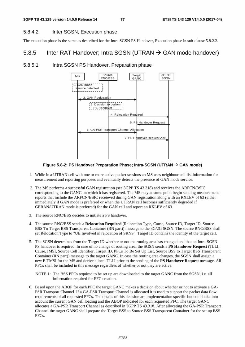
ETSI
ETSI TS 143 129 V14.0.0 (2017-04)773GPP TS 43.129 version 14.0.0 Release 14
5.8.4.2 Inter SGSN, Execution phase
The execution phase is the same as described for the Intra SGSN PS Handover, Execution phase in sub-clause 5.8.2.2.
5.8.5 Inter RAT Handover; Intra SGSN (UTRAN � GAN mode handover)
5.8.5.1 Intra SGSN PS Handover, Preparation phase
MS Target GANC
Source RNC/BSS
3G/2G SGSN
1. GAN mode service detected
2. GAN Registration
4. Relocation Required
5. PS Handover Request
7. PS Handover Request Ack
6. GA-PSR Transport Channel Allocation
3. Decision to perform PS Handover
Figure 5.8-2: PS Handover Preparation Phase; Intra-SGSN (UTRAN � GAN mode)
1. While in a UTRAN cell with one or more active packet sessions an MS uses neighbour cell list information for measurement and reporting purposes and eventually detects the presence of GAN mode service.
2. The MS performs a successful GAN registration (see 3GPP TS 43.318) and receives the ARFCN/BSIC corresponding to the GANC on which it has registered. The MS may at some point begin sending measurement reports that include the ARFCN/BSIC receieved during GAN registration along with an RXLEV of 63 (either immediately if GAN mode is preferred or when the UTRAN cell becomes sufficiently degraded if GERAN/UTRAN mode is preferred) for the GAN cell and report an RXLEV of 63.
3. The source RNC/BSS decides to initiate a PS handover.
4. The source RNC/BSS sends a Relocation Required (Relocation Type, Cause, Source ID, Target ID, Source BSS To Target BSS Transparent Container (RN part)) message to the 3G/2G SGSN. The source RNC/BSS shall set Relocation Type to "UE Involved in relocation of SRNS". Target ID contains the identity of the target cell.
5. The SGSN determines from the Target ID whether or not the routing area has changed and that an Intra-SGSN PS handover is required. In case of no change of routing area, the SGSN sends a PS Handover Request (TLLI, Cause, IMSI, Source Cell Identifier, Target ID, PFCs To Be Set Up List, Source BSS to Target BSS Transparent Container (RN part)) message to the target GANC. In case the routing area changes, the SGSN shall assign a new P-TMSI for the MS and derive a local TLLI prior to the sending of the PS Handover Request message. All PFCs shall be included in this message regardless of whether or not they are active.
NOTE 1: The BSS PFCs required to be set up are downloaded to the target GANC from the SGSN, i.e. all information required for PFC creation.
6. Based upon the ABQP for each PFC the target GANC makes a decision about whether or not to activate a GA-PSR Transport Channel. If a GA-PSR Transport Channel is allocated it is used to support the packet data flow requirements of all requested PFCs. The details of this decision are implementation specific but could take into account the current GAN cell loading and the ABQP indicated for each requested PFC. The target GANC allocates a GA-PSR Transport Channel as described in 3GPP TS 43.318. After allocating the GA-PSR Transport Channel the target GANC shall prepare the Target BSS to Source BSS Transparent Container for the set up BSS PFCs.
ETSI
ETSI TS 143 129 V14.0.0 (2017-04)783GPP TS 43.129 version 14.0.0 Release 14
7. The target GANC sends the PS Handover Request Acknowledge (TLLI, List of Set Up PFCs, Target BSS to Source BSS Transparent Container (RN part)) message to the SGSN. Upon sending the PS Handover Request Acknowledge message the target GANC shall be prepared to receive downlink LLC PDUs from the SGSN for all requested PFCs (i.e. the List of Set Up PFCs in this message shall always match the PFCs To Be Set Up List included in the corresponding PS Handover Request message since a GA-PSR Transport Channel is allocated with the intent of supporting all PFCs requested by the SGSN).
When the SGSN receives the PS Handover Request Acknowledge message and it decides to proceed with the handover, the preparation phase is finished and the execution phase will follow.
5.8.5.2 Intra SGSN PS Handover, Execution phase
The execution phase is the same as described for Intra SGSN, UTRAN/GERAN Iu mode to GERAN A/Gb mode PS handover except for the following:
• The RNC sends the Handover from UTRAN Command message to the MS where each message includes a PS Handover Command message where the RN part does not include any of the optional information.
• After receiving the Handover from UTRAN Command message in the source cell the MS determines that the indicated ARFCN and BSIC match those of the GAN cell that it last registered on and therefore does not perform system synchronization in the GAN cell. Instead, the MS enables the transmission of uplink LLC PDUs on the allocated GA-PSR Transport Channel and sends a GA-PSR HANDOVER COMPLETE message to the target GANC. Note that the reception of downlink LLC PDUs is enabled in the MS upon allocation of the GA-PSR Transport Channel during the preparation phase.
• Upon reception of the GA-PSR HANDOVER COMPLETE message from the MS in the GAN cell the target GANC sends a PS Handover Complete (TLLI, IMSI, Target Cell Identifier) message to the SGSN.
5.8.6 Inter RAT Handover; Intra SGSN (GAN mode �UTRAN handover)
5.8.6.1 Intra SGSN PS Handover, Preparation phase
The preparation phase is the same as described for Intra SGSN, GERAN A/Gb mode to UTRAN/GERAN Iu mode PS handover except for the following:
• While in a GAN cell an MS sends the GA-PSR HANDOVER INFORMATION message to the GANC indicating a list of target UTRAN cells, identified by a combination of LAI and 3G Cell Identity/CGI, in order of preference for PS handover, and includes the received signal strength for each identified UTRAN cell. The MS decision to send the GA-PSR HANDOVER INFORMATION may be based on local measurements in the MS (see 3GPP TS 44.318 [28]). This list is the most recent information available from the UTRAN RRC/GSM RR subsystem. In addition, the GA-PSR HANDOVER INFORMATION message may include a list of target GERAN A/Gb mode cells ranked in order of preference for PS handover, and the received signal strength for each identified GERAN A/Gb mode cell.
• The source GANC selects a target UTRAN cell and triggers the PS handover preparation phase by signalling to the SGSN the need for PS handover (i.e. it sends the PS Handover Required message) and including the target UTRANcell.
• When the source GANC decides to trigger a PS handover both uplink and downlink user data is transmitted via the GA-PSR Transport Channel between MS and source GANC, BSSGP PFCs tunnel(s) between the source GANC and SGSN, GTP tunnel(s) between the SGSN and GGSN.
5.8.6.2 Intra SGSN, Execution phase
The execution phase is the same as described for Intra SGSN, GERAN A/Gb mode to UTRAN/GERAN Iu mode PS handover except for the following:
• The SGSN sends a PS Handover Required Acknowledge (Old TLLI, List of Set Up PFCs, Target BSS to Source BSS Transparent Container (RN part)) message to the source GANC.
• Before sending the GA-PSR HANDOVER COMMAND message to the MS the source GANC, based on QoS, may try to empty the downlink GANC buffer for one or more PFCs.
ETSI
ETSI TS 143 129 V14.0.0 (2017-04)793GPP TS 43.129 version 14.0.0 Release 14
• The source GANC interrupts the downlink transmission of LLC PDUs on the GA-PSR Transport Channel and sends the MS a GA-PSR HANDOVER COMMAND message that includes a Handover to UTRAN Command message (as specified in 3GPP TS 25.331 [17]) created by the target RNC.
5.8.7 Inter RAT Handover; Inter SGSN (UTRAN � GAN mode handover)
5.8.7.1 Inter SGSN PS Handover, Preparation phase
The preparation phase is the same as described for Intra SGSN, UTRAN to GAN mode PS handover except that Inter-SGSN communications are required and are as described for Inter-SGSN UTRAN to A/Gb mode PS handover.
5.8.7.2 Inter SGSN PS Handover, Execution phase
The execution phase is the same as described for the Intra SGSN PS Handover, Execution phase in sub-clause 5.8.5.2.
5.8.8 Inter RAT Handover; Inter SGSN (GAN mode � UTRAN handover)
5.8.8.1 Inter SGSN PS Handover, Preparation phase
The preparation phase is the same as described for Inter SGSN, GERAN A/Gb mode to UTRAN/GERAN Iu mode PS handover except for the following:
• While in a GAN cell an MS sends the GA-PSR HANDOVER INFORMATION message to the GANC indicating a list of target UTRAN cells, identified by a combination of LAI and 3G Cell Identity/CGI, in order of preference for PS handover, and includes the received signal strength for each identified UTRAN cell. The MS decision to send the GA-PSR HANDOVER INFORMATION message may be based on local measurements in the MS (see 3GPP TS 44.318 [28]). This list is the most recent information available from the UTRAN RRC/GSM RR subsystem. In addition, the GA-PSR HANDOVER INFORMATION message may include a list of target GERAN A/Gb mode cells ranked in order of preference for PS handover, and the received signal strength for each identified GERAN A/Gb mode cell.
• The source GANC selects a target UTRAN cell and triggers the PS handover preparation phase by signalling to the SGSN the need for PS handover (i.e. it sends the PS Handover Required message) and including the target UTRAN cell.
• When the source GANC decides to trigger a PS handover both uplink and downlink user data is transmitted via the GA-PSR Transport Channel between MS and source GANC, BSSGP PFCs tunnel(s) between the source GANC and SGSN, and GTP tunnel(s) between the SGSN and GGSN.
5.8.8.2 Inter SGSN PS Handover, Execution phase
The execution phase is the same as described for the Intra SGSN, Execution phase in sub-clause 5.8.6.2.
6 Radio interface Signalling
6.1 PS Handover Signalling (Um)
6.1.1 General
PS Handover signalling includes the set of all air interface messages (Um signalling for A/Gb mode, Up signalling for GAN mode and Uu signalling for Iu mode) sent to or from the MS in the source and target cells during the PS handover procedure.
ETSI
ETSI TS 143 129 V14.0.0 (2017-04)803GPP TS 43.129 version 14.0.0 Release 14
6.1.2 Overview of PS Handover messages
6.1.2.1 GERAN A/Gb mode/GAN mode to GERAN A/Gb mode PS Handover
When performing an inter-SGSN PS Handover from GERAN A/Gb mode/GAN mode to GERAN A/Gb mode the following information is sent over the Um and Up interfaces.
• PS Handover Command message (for PS handover from GERAN A/Gb mode) or a GA-PSR HANDOVER COMMAND message including a PS Handover Command message (for PS handover from GAN mode) - sent to the MS in the source cell and includes the following:
- optionally, the NAS container for PS HO
- Indication of the radio resources for uplink and downlink TBFs to be used in the target cell for each PFC receiving PS handover treatment (i.e. the reverse path container created by target BSS/RNC).
- Indication of a PS handover reference number to be used when the MS arrives in the target cell.
• PS Handover Access message - the MS sends 4 handover access bursts in the target cell using an uplink TBF provided by the PS Handover Command. If multiple uplink TBFs are provided by the PS Handover Command message the MS sends access bursts using just one of these TBFs (i.e. at minimum one uplink TBF must be provided in the PS Handover Command message). The handover reference number is included within each access burst. This message is always sent for the case of non-synchronised handover and may still be sent for the case of synchronised or pre-synchronised handovers (determined by the target BSS during the PS handover preparation phase) to allow the target BSS to verify the accessing MS.
• Packet Physical Information message - sent by the target BSS to the MS in the target cell in response to the PS Handover Access message for the case of unsynchronised cells. Whether or not this message is sent in case of synchronised cells is indicated by the PS Handover command message (see 3GPP TS 44.018 [25]). It is sent using the downlink PACCH associated with the uplink TBF used to send the access bursts and provides the MS with physical layer information (i.e. Timing Advance). The time alignment information received in this message applies to all uplink TBFs allocated to the MS in the PS Handover Command message. The target BSS only sends this information if it receives the expected handover reference number in a PS Handover Access message.
• Uplink RLC Data Blocks - sent on uplink TBFs allocated by the PS Handover Command message after the MS receives Packet Physical Information message as follows:
- For inter-SGSN PS handover the MS, prior to sending any uplink user plane payload for any PFC, shall send an XID Response message .
• Downlink RLC Data Blocks - sent on downlink TBFs allocated by the PS Handover Command message as follows:
- For inter-SGSN PS handover for a given PFC the new SGSN may begin downlink N-PDU transmissions for that PFC prior to receiving a PS Handover Complete message (i.e. blind transmission may be used) or it may wait for a PS Handover Complete message before beginning downlink N-PDU transmissions for that PFC.
• GA-PSR HANDOVER INFORMATION message (for PS handover from GAN mode) – sent from the MS to the GANC to provide a list of target GERAN A/Gb mode cells, identified by CGI, in order of preference for PS handover, and includes the received signal strength for each identified GERAN A/Gb mode cell.
• GA-PSR UPLINK QUALITY INDICATION message (for PS handover from GAN mode) – sent from the GANC to the MS to provide it with PS service related information as perceived by the GANC which may result in the MS triggering the PS handover procedure (i.e. sending a GA-PSR HANDOVER INFORMATION message).
6.1.2.2 UTRAN/GERAN Iu mode to GERAN A/Gb mode/GAN mode PS Handover
When performing a PS Handover from UTRAN/GERAN Iu mode to GERAN A/Gb mode or from UTRAN to GAN mode the following the following information is sent over the Uu, Up and Um interfaces:
ETSI
ETSI TS 143 129 V14.0.0 (2017-04)813GPP TS 43.129 version 14.0.0 Release 14
• RRC Message - sent to the MS in the source cell and includes the same information described for the PS Handover Command in clause 6.1.2.1.
• For PS handover from UTRAN to GERAN A/Gb mode/GAN mode the Handover from UTRAN Command (3GPP TS 25.331 [17]) message is used in CELL_DCH and CELL_FACH state when only PS RABs are established.
• For PS handover from GERAN Iu mode to GERAN A/Gb mode the HANDOVER FROM GERAN IU COMMAND message is used in RRC-Cell_Dedicated (MAC Dedicated or MAC DTM state) or RRC-Cell_Shared state when only PS RABs are established.
• PS Handover Access message (for PS handover to GERAN A/Gb mode) - sent as described in clause 6.1.2.1.
• Packet Physical Information message (for PS handover to GERAN A/Gb mode) - sent as described in clause 6.1.2.1.
• Uplink RLC Data Blocks (for PS handover to GERAN A/Gb mode) - sent as described in clause 6.1.2.1.
• Downlink RLC Data Blocks (for PS handover to GERAN A/Gb mode) - sent as described in clause 6.1.2.1.
• The target BSS/GANC may begin downlink LLC PDU transmissions prior to confirming the successful completion of the PS handover procedure (i.e. blind transmission may be used) or it may wait for an uplink RLC data block (target BSS) or a GA-PSR HANDOVER COMPLETE message (GANC) before beginning downlink N-PDU transmissions.
• GA-PSR ACTIVATE UTC REQ message (for PS handover from UTRAN to GAN mode) – sent to the MS from the target GANC to activate the transport channel to be used in the GAN cell.
• GA-PSR ACTIVATE UTC ACK message (for PS handover from UTRAN to GAN mode) – sent from the MS to the target GANC to confirm allocation of the transport channel to be used in the GAN cell.
• GA-PSR HANDOVER COMPLETE message (for PS handover from UTRAN to GAN mode) – sent from the MS to the target GANC to indicate handover completion.
6.1.2.3 GERAN A/Gb mode to GERAN Iu mode PS Handover
When performing a PS Handover from GERAN A/Gb mode to GERAN Iu mode the following information is sent over the Uu and Um interfaces:
• PS Handover Command message - sent to the MS in the source cell and includes the following:
- System broadcast information applicable to the target cell.
- Indication of the radio resources for uplink and downlink TBFs to be used in the target cell for each RAB receiving PS handover treatment (i.e. the reverse path container created by target BSS). Note that the MS will map the N-SAPI associated with each of its active PDP Contexts directly to a RABid (i.e. N-SAPI = RABid).
- Indication of a PS handover reference number to be used when the MS arrives in the target cell.
• PS Handover Access message - sent as described in clause 6.1.2.1.
• Packet Physical Information message - sent as described in clause 6.1.2.1.
• RRC message (e.g. Physical Channel Reconfiguration Complete) - content is GERAN Iu mode specific.
• Uplink RLC Data Blocks - sent on uplink TBFs allocated by the PS Handover Command message after the MS receives Physical Layer Information (content is GERAN Iu mode specific).
• Downlink RLC Data Blocks - sent on downlink TBFs allocated by the PS Handover Command message (content is GERAN Iu mode specific).
ETSI
ETSI TS 143 129 V14.0.0 (2017-04)823GPP TS 43.129 version 14.0.0 Release 14
6.1.2.4 GERAN A/Gb mode/GAN mode to UTRAN mode PS Handover
When performing a PS Handover from GERAN A/Gb mode/GAN mode to UTRAN mode the following information is sent over the Uu, Up and Um interfaces:
• PS Handover Command message (for PS handover from GERAN A/Gb mode) or GA-PSR HANDOVER COMMAND message (for PS handover from GAN mode) - sent to the MS in the source cell. It includes the reverse path container created by the target RNC that consists of the RRC message (i.e. the Handover to UTRAN Command) required to perform PS handover to UTRAN.
• MS Detected by Target RNC - exact procedure and information transfer is UTRAN specific.
• RRC message (e.g. Physical Channel Reconfiguration Complete) - information content is UTRAN specific.
• GA-PSR HANDOVER INFORMATION message (for PS handover from GAN mode) – sent from the MS to the GANC to provide a list of target UTRAN cells, identified by a combination of LAI and 3G Cell Identity, in order of preference for PS handover, and includes the received signal strength for each identified UTRAN cell.
• GA-PSR UPLINK QUALITY INDICATION message (for PS handover from GAN mode) – sent from the GANC to the MS to provide it with PS service related information as perceived by the GANC which may result in the MS triggering the PS handover procedure (i.e. sending a GA-PSR HANDOVER INFORMATION message).
6.1.2.5 GERAN A/Gb mode to GAN mode PS Handover
When performing an inter-SGSN PS Handover from GERAN A/Gb mode to GAN mode the following information is sent over the Um and Up interfaces.
• PS Handover Command message - sent to the MS in the source cell and includes the following:
- optionally, the NAS container for PS HO.
- RN information which consists only of the mandatory fields within the PS Handover Radio Resources IE carried within the PS Handover Command message.
• The target GANC may begin downlink LLC PDU transmissions prior to confirming the successful completion of the PS handover procedure (i.e. blind transmission may be used) or it may wait for a GA-PSR HANDOVER COMPLETE message before beginning downlink N-PDU transmissions.
• GA-PSR ACTIVATE UTC REQ message – sent to the MS from the target GANC to activate the transport channel to be used in the GAN cell.
• GA-PSR ACTIVATE UTC ACK message – sent from the MS to the target GANC to confirm allocation of the transport channel to be used in the GAN cell.
• GA-PSR HANDOVER COMPLETE message – sent from the MS to the target GANC to indicate handover completion.
6.1.2.6 GERAN A/Gb mode to E-UTRAN PS Handover
When performing a PS Handover from GERAN A/Gb mode to E-UTRAN the following information is sent over the radio interface:
- PS Handover Command message (for PS handover from GERAN A/Gb mode) to the MS in the source cell (on the Um interface). It includes the reverse path container created by the target eNB that consists of the RRC message (i.e. the RRCConnectionReconfiguration message) required to perform PS handover to E-UTRAN.
- MS Detected by Target eNB- the exact procedure and information transfer on the Uu interface is E-UTRAN specific 3GPP TS36.300 [30], 3GPP TS36.331 [31].
- RRC message on the Uu interface - information content is E-UTRAN specific TS36.331 [31].
ETSI
ETSI TS 143 129 V14.0.0 (2017-04)833GPP TS 43.129 version 14.0.0 Release 14
6.1.2.7 E-UTRAN to GERAN A/Gb mode PS Handover
When performing a PS Handover from E-UTRAN to GERAN A/Gb mode the following information is sent over the radio interface:
- RRC Message - sent to the MS in the source cell (on the Uu interface). It includes the same information described for the PS Handover Command in sub-clause 6.1.2.1.
- The MobilityFromEUTRACommand (3GPP TS 36.331 [31]) message is sent to the UE (on the Uu interface).
- PS Handover Access message (for PS handover to GERAN A/Gb mode) – sent on the Um interface as described in sub-clause 6.1.2.1.
- Packet Physical Information message (for PS handover to GERAN A/Gb mode) – sent on the Um interface as described in sub-clause 6.1.2.1.
- Uplink RLC Data Blocks (for PS handover to GERAN A/Gb mode) - sent on the Um interface as described in sub-clause 6.1.2.1.
- Downlink RLC Data Blocks (for PS handover to GERAN A/Gb mode) - sent on the Um interface as described in sub-clause 6.1.2.1.
- The target BSS may begin downlink LLC PDU transmissions prior to confirming the successful completion of the PS handover procedure (i.e. blind transmission may be used) or it may wait for an uplink RLC data block (target BSS).
6.1.3 RLC/MAC segmentation
RLC/MAC segmentation is a feature that provides an additional mechanism for sending control plane messages from the BSS to the MS. This feature can only be used after contention resolution is completed in the BSS and the BSS has to send an RLC/MAC control message that is from 3 to 9 radio blocks long.
6.1.4 Inter RAT/mode PS Handover to GERAN A/Gb
Void.
6.1.5 Inter RAT/mode PS Handover from GERAN A/Gb
Void.
6.2 Mechanisms for Initial Access in the Target Cell
6.2.1 General
This clause describes two possible approaches to the MS making access in the target cell. Both basic approaches assume that a handover procedure similar to that for the CS domain (Handover Access followed by Physical Information messages) takes place.
The effect of synchronised networks is examined for both approaches where the exchange of Handover Access and Physical Information is not required as the TA can be derived in advance.
The main assumptions applicable to the call flows are:
• USFs are required to schedule uplink data blocks.
• All identifiers and resources are known by the MS and target BSS before the MS makes the initial access in the target cell.
ETSI
ETSI TS 143 129 V14.0.0 (2017-04)843GPP TS 43.129 version 14.0.0 Release 14
6.2.2 Synchronisation of handovers
The following synchronisation mechanisms are used for PS handover:
• Non-synchronised.
• Synchronised.
• Pre-Synchronised.
The non-synchronised cases are shown in figures 22 and 24 and are characterised by the requirement for the MS to obtain a valid uplink timing advance before it can transmit normal bursts. The MS shall notify its presence in the target cell through the transmission of access bursts to the BSS, and the BSS shall respond with a valid timing advance which in turn enables the MS to send normal bursts in uplink.
The synchronised and pre-synchronised cases are shown in figures 23 and 25 and have different mechanisms for the provision of the timing advance that are described in 3GPP TS 45.010 [26].
NOTE: The pseudo-synchronised case is not supported by the PS handover feature.
6.2.3 Option 1 - Downlink Data sent after performing access in the target cell
In this approach, downlink data is not transmitted until the BSS has been made aware of the presence of the MS via the reception of a PS Handover Access message.
6.2.3.1 Unsynchronised Networks Call Flow
The message flow for this option is shown in figure 22. The MS starts by sending PS Handover Access messages as four access bursts to the network (through USF allocation). As there is no contention, the network should receive at least one of the access bursts. A Handover Reference parameter is allocated by the target BSS in the PS Handover Command message and included in the PS Handover Access message to verify that the correct MS is accessing the resources. This is similar to the Handover Reference in the CS handover case.
The BSS receives the PS Handover Access message and detects that the correct MS has now made access in the target cell. It sends a Packet Physical Information message to indicate that the MS has been detected. The main purpose of this message is to give the Timing Advance information to the MS.
Once the MS has received the Packet Physical Information message it sends uplink LLC PDUs (user or signalling data, depending on the scenario). When correctly receiving the first RLC data block from the MS the target BSS verifies the mobile station, generates a PS Handover Complete message and sends it to the new SGSN.
The MS can start sending uplink RLC/MAC data blocks on the pre-allocated resources when scheduled with its USF. When the PS Handover Complete message has been received by the new SGSN, it can start sending downlink data blocks.
NOTE: The downlink RLC data blocks can be sent for any PFC receiving PS handover treatment after the target BSS has confirmed that the correct MS is present and after the PS Handover Complete message has been received by the new SGSN.
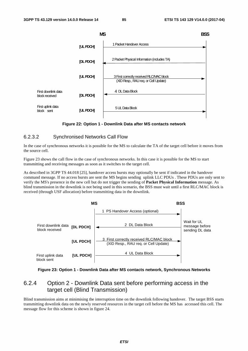
ETSI
ETSI TS 143 129 V14.0.0 (2017-04)853GPP TS 43.129 version 14.0.0 Release 14
MS BSS
1 Packet Handover Access [UL PDCH]
[DL PDCH] 2 Packet Physical Information (includes TA)
5 UL Data Block [UL PDCH]
[DL PDCH] 4 DL Data Block
3 First correctly received RLC/MAC block (XID Resp., RAU req. or Cell Update)
[UL PDCH]
First uplink data block sent
First downlink data block received
Figure 22: Option 1 - Downlink Data after MS contacts network
6.2.3.2 Synchronised Networks Call Flow
In the case of synchronous networks it is possible for the MS to calculate the TA of the target cell before it moves from the source cell.
Figure 23 shows the call flow in the case of synchronous networks. In this case it is possible for the MS to start transmitting and receiving messages as soon as it switches to the target cell.
As described in 3GPP TS 44.018 [25], handover access bursts may optionally be sent if indicated in the handover command message. If no access bursts are sent the MS begins sending uplink LLC PDUs . These PDUs are only sent to verify the MS's presence in the new cell but do not trigger the sending of Packet Physical Information message. As blind transmission in the downlink is not being used in this scenario, the BSS must wait until a first RLC/MAC block is received (through USF allocation) before transmitting data in the downlink.
Figure 23: Option 1 - Downlink Data after MS contacts network, Synchronous Networks
6.2.4 Option 2 - Downlink Data sent before performing access in the target cell (Blind Transmission)
Blind transmission aims at minimising the interruption time on the downlink following handover. The target BSS starts transmitting downlink data on the newly reserved resources in the target cell before the MS has accessed this cell. The message flow for this scheme is shown in figure 24.
MS BSS
3 First correctly received RLC/MAC block (XID Resp., RAU req. or Cell Update)
[UL PDCH]
4 UL Data Block [UL PDCH]
2 DL Data Block [DL PDCH] Wait for UL message before sending DL data
First downlink data block received
First uplink data block sent
1 PS Handover Access (optional)
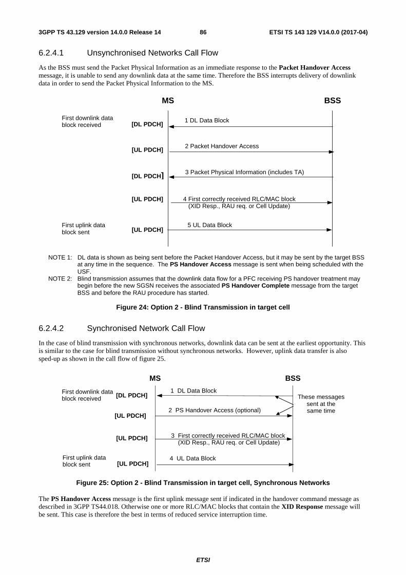
ETSI
ETSI TS 143 129 V14.0.0 (2017-04)863GPP TS 43.129 version 14.0.0 Release 14
6.2.4.1 Unsynchronised Networks Call Flow
As the BSS must send the Packet Physical Information as an immediate response to the Packet Handover Access message, it is unable to send any downlink data at the same time. Therefore the BSS interrupts delivery of downlink data in order to send the Packet Physical Information to the MS.
NOTE 1: DL data is shown as being sent before the Packet Handover Access, but it may be sent by the target BSS at any time in the sequence. The PS Handover Access message is sent when being scheduled with the USF.
NOTE 2: Blind transmission assumes that the downlink data flow for a PFC receiving PS handover treatment may begin before the new SGSN receives the associated PS Handover Complete message from the target BSS and before the RAU procedure has started.
Figure 24: Option 2 - Blind Transmission in target cell
6.2.4.2 Synchronised Network Call Flow
In the case of blind transmission with synchronous networks, downlink data can be sent at the earliest opportunity. This is similar to the case for blind transmission without synchronous networks. However, uplink data transfer is also sped-up as shown in the call flow of figure 25.
MS BSS
3 First correctly received RLC/MAC block ( XID Resp., RAU req. or Cell Update)
1 DL Data Block
[UL PDCH]
[UL PDCH]
These messages sent at the same time
First downlink data block received
First uplink data block sent
4 UL Data Block
2 PS Hand over Access (optional) [UL PDCH]
[DL PDCH]
Figure 25: Option 2 - Blind Transmission in target cell, Synchronous Networks
The PS Handover Access message is the first uplink message sent if indicated in the handover command message as described in 3GPP TS44.018. Otherwise one or more RLC/MAC blocks that contain the XID Response message will be sent. This case is therefore the best in terms of reduced service interruption time.
MS BSS
2 Packet Handover Access [UL PDCH]
[DL PDCH] 3 Packet Physical Information (includes TA)
1 DL Data Block [DL PDCH]
First downlink data block received
[UL PDCH] 5 UL Data Block
4 First correctly received RLC/MAC block (XID Resp., RAU req. or Cell Update)
[UL PDCH]
First uplink data block sent
ETSI
ETSI TS 143 129 V14.0.0 (2017-04)873GPP TS 43.129 version 14.0.0 Release 14
NOTE: Blind transmission assumes that the flow of downlink data for a PFC receiving PS handover treatment may begin before the new SGSN receives the PS Handover Complete message from the target BSS and before the RAU procedure has started.
6.3 Methods for triggering PS Handover A PS Handover is triggered by the BSS based on the received measurement reports or initiated by the reception of the Packet Cell Change Notification message from the mobile station. The BSS controls which of the two methods to use for initiating the PS Handover.
A PS Handover is triggered by the GANC based on the measurement reports received in the GA-PSR HANDOVER INFORMATION message or by other trigger conditions (see 3GPP TS 44.318 [28]).
When PS Handover is triggered by the BSS based on the measurement reports, the mobile station is in NC2 mode. The mobile station sends measurement reports to the network (BSS). When the network has found a new cell meeting the cell reselection criteria, and prepared for the PS Handover in that target cell, it sends the PS Handover Command message to the mobile station.
If not in NC2 mode, the mobile station may, by transmitting a Packet Cell Change Notification message according to the Cell Change Notification procedure, make the BSS aware it has found a new cell meeting the cell reselection criteria. The network then prepares for the PS Handover in the indicated target cell and sends the PS Handover Command message to the mobile station. In order to avoid that the mobile station performs autonomous cell reselection due to timeout of T3208, the network can order the mobile station to enter NC2 mode by transmitting the Packet Measurement Order message in response to the PCCN message. This will keep the mobile station in the cell until the PS Handover Command message is sent by the network, thus making it possible for the network to perform all necessary PS handover signalling and set up the radio resources in the target cell.
ETSI
ETSI TS 143 129 V14.0.0 (2017-04)883GPP TS 43.129 version 14.0.0 Release 14
Annex A (normative): Agreed handover principles
A.1 Agreed handover principles 1. It is the mobile station that is handed over to a target cell when one or more of its PFCs are subject to
handover.
2. The source BSS makes the decision to initiate the handover preparation phase when required for PFC(s) subject to handover.
3. Information pertaining to all PDP contexts and PFCs relating to the MS should be sent from the old SGSN to the target SGSN in the handover signalling regardless of their QoS.
4. The target BSS should make the final decision on which PFCs are subject to handover and to assign resources over the Um interface in the target cell. This decision is based on the target BSS being able to fulfil the QoS for these PFCs.
5. The old SGSN decides whether and when to forward data to the TEIDs provided by the new SGSN.
6. It is not required to have resources allocated in advance for bearers which themselves are not determined to be subject to handover by the target BSS.
7. How the target BSS decides which PFCs to accept and which to reject should be implementation specific.
8. For the PS Handover, forwarding of data is performed from the old SGSN either to the target BSS (intra BSS, intra SGSN-inter BSS) or to the new SGSN (inter SGSN); an optional optimisation for intra BSS handover will allow the BSS to decide how to handle the user data flow.
9. An explicit Routing Area Update procedure is performed (if required) when the handover procedure is terminated.
10. The explicit RAU may not contain the following message sequences that are performed already during the handover procedure:
- Transfer of contexts between SGSNs (inter SGSN case).
- Exchange of SNDCP sequence numbers (inter SGSN case).
- Allocation of P-TMSI.
11. Uplink and downlink data transfer continues during the Routing Area Update procedure. This is possible because certain RAU centric functions are performed during the handover execution phase.
12. The PS Handover service shall support intra BSS, intra SGSN-inter BSS, inter SGSN and inter RAT scenarios.
13. Based on the quality of service parameters the MS or the network may throw away packets available for transmission in the uplink or downlink during the ongoing handover procedure.
14. The source BSS shall only request PS handover for one cell in each PS Handover Required message.
15. The PS handover procedure is only performed when the target BSS pre-allocates resource for at least one PFC. In case the target BSS cannot allocate resources for at least one PFC the target BSS shall reject the PS Handover request using the PS Handover Request Negative Acknowledge message.
16. In case the mobile fails to synchronize to the target cell within a timeout period after having received a PS Handover Command, shall revert to the source cell and the old "channels".
17. Optionally, in the case of Intra RAT/Mode PS handover, information pertaining to the radio resource realization of the PFCs subject to Handover can be transferred from the source BSS to the target BSS.
18. During the PS Handover preparation phase the new SGSN (assuming RA change) assigns a unique identifier (P-TMSI, Local TLLI) for data transmission in the target cell. This Local TLLI is used for data transfer
ETSI
ETSI TS 143 129 V14.0.0 (2017-04)893GPP TS 43.129 version 14.0.0 Release 14
between the target BSS and the new SGSN. This Local TLLI is not sent to the MS. After PS Handover Completion the MS triggers the RAU procedure. After P-TMSI reallocation, which is performed during Routing area update, a new Local TLLI will be derived from the P-TMSI using current MM procedures.
19. An SGSN supporting PS handover to GERAN A/Gb mode shall always assign a valid SAPI and PFI upon PDP Context activation for a PS Handover capable MS.
20. An MME supporting PS handover to GERAN A/Gb mode shall always assign a valid SAPI and PFI upon EPS bearer activation for a PS Handover capable MS.
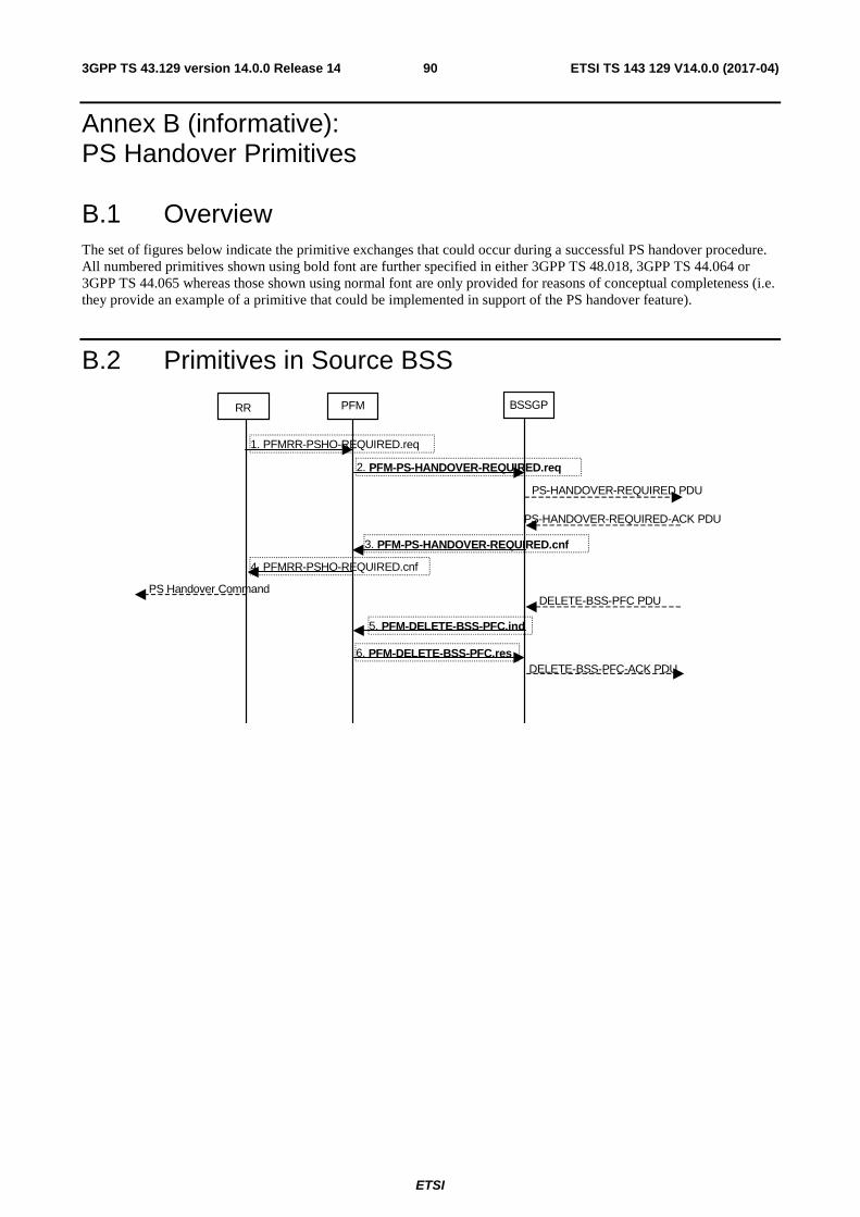
ETSI
ETSI TS 143 129 V14.0.0 (2017-04)903GPP TS 43.129 version 14.0.0 Release 14
Annex B (informative): PS Handover Primitives
B.1 Overview The set of figures below indicate the primitive exchanges that could occur during a successful PS handover procedure. All numbered primitives shown using bold font are further specified in either 3GPP TS 48.018, 3GPP TS 44.064 or 3GPP TS 44.065 whereas those shown using normal font are only provided for reasons of conceptual completeness (i.e. they provide an example of a primitive that could be implemented in support of the PS handover feature).
B.2 Primitives in Source BSS
RR PFM BSSGP
2. PFM-PS-HANDOVER-REQUIRED.req
3. PFM-PS-HANDOVER-REQUIRED.cnf
1. PFMRR-PSHO-REQUIRED.req
4. PFMRR-PSHO-REQUIRED.cnf
PS-HANDOVER-REQUIRED PDU
PS-HANDOVER-REQUIRED-ACK PDU
PS Handover Command DELETE-BSS-PFC PDU
5. PFM-DELETE-BSS-PFC.ind
6. PFM-DELETE-BSS-PFC.res DELETE-BSS-PFC-ACK PDU
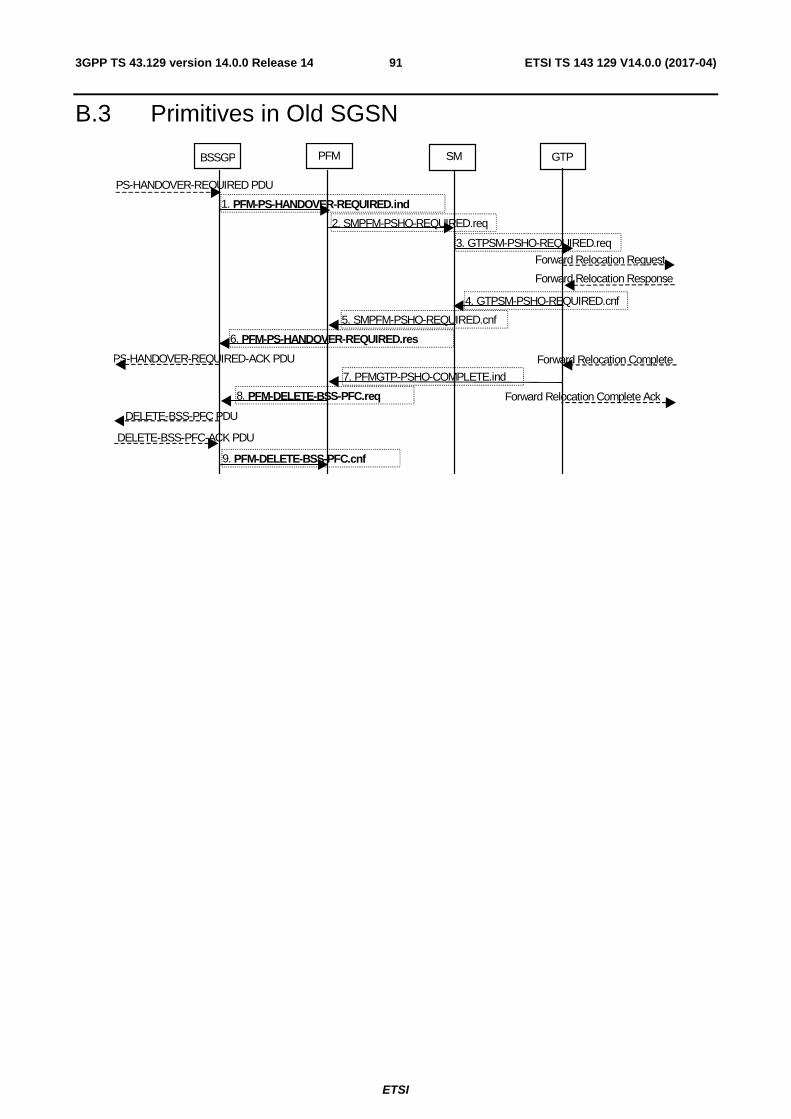
ETSI
ETSI TS 143 129 V14.0.0 (2017-04)913GPP TS 43.129 version 14.0.0 Release 14
B.3 Primitives in Old SGSN
BSSGP PFM SM
2. SMPFM-PSHO-REQUIRED.req
3. GTPSM-PSHO-REQUIRED.req
4. GTPSM-PSHO-REQUIRED.cnf
5. SMPFM-PSHO-REQUIRED.cnf
GTP
1. PFM-PS-HANDOVER-REQUIRED.ind
PS-HANDOVER-REQUIRED PDU
Forward Relocation Request
Forward Relocation Response
PS-HANDOVER-REQUIRED-ACK PDU Forward Relocation Complete
7. PFMGTP-PSHO-COMPLETE.ind
8. PFM-DELETE-BSS-PFC.req
DELETE-BSS-PFC PDU
6. PFM-PS-HANDOVER-REQUIRED.res
DELETE-BSS-PFC-ACK PDU
9. PFM-DELETE-BSS-PFC.cnf
Forward Relocation Complete Ack
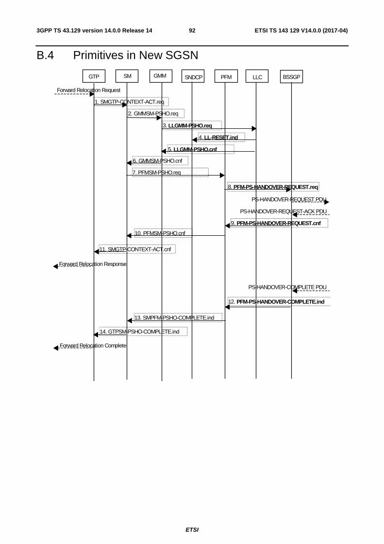
ETSI
ETSI TS 143 129 V14.0.0 (2017-04)923GPP TS 43.129 version 14.0.0 Release 14
B.4 Primitives in New SGSN
GTP GMM SM SNDCP PFM LLC
1. SMGTP-CONTEXT-ACT.req
2. GMMSM-PSHO.req
6. GMMSM-PSHO.cnf
3. LLGMM-PSHO.req
5. LLGMM-PSHO.cnf
BSSGP
7. PFMSM-PSHO.req
8. PFM-PS-HANDOVER-REQUEST.req
10. PFMSM-PSHO.cnf
11. SMGTP-CONTEXT-ACT.cnf
Forward Relocation Request
PS-HANDOVER-REQUEST PDU
PS-HANDOVER-REQUEST-ACK PDU
Forward Relocation Response
PS-HANDOVER-COMPLETE PDU
12. PFM-PS-HANDOVER-COMPLETE.ind
13. SMPFM-PSHO-COMPLETE.ind
14. GTPSM-PSHO-COMPLETE.ind
Forward Relocation Complete
9. PFM-PS-HANDOVER-REQUEST.cnf
4. LL-RESET.ind
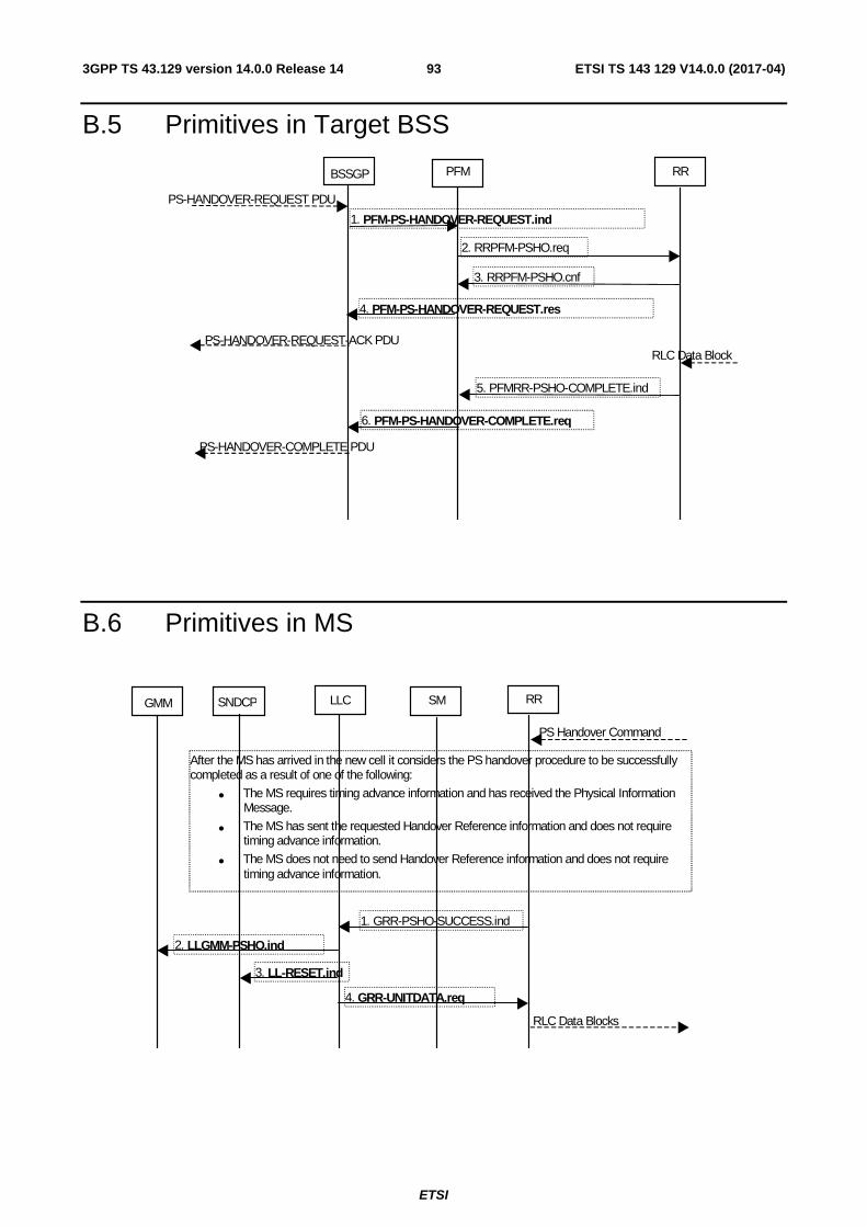
ETSI
ETSI TS 143 129 V14.0.0 (2017-04)933GPP TS 43.129 version 14.0.0 Release 14
B.5 Primitives in Target BSS
BSSGP RR
1. PFM-PS-HANDOVER-REQUEST.ind
PS-HANDOVER-REQUEST PDU
2. RRPFM-PSHO.req
RLC Data Block
PFM
5. PFMRR-PSHO-COMPLETE.ind
6. PFM-PS-HANDOVER-COMPLETE.req
PS-HANDOVER-COMPLETE PDU
3. RRPFM-PSHO.cnf
PS-HANDOVER-REQUEST-ACK PDU
4. PFM-PS-HANDOVER-REQUEST.res
B.6 Primitives in MS
GMM SM RR
1. GRR-PSHO-SUCCESS.ind
PS Handover Command
LLC
RLC Data Blocks
4. GRR-UNITDATA.req
2. LLGMM-PSHO.ind
SNDCP
After the MS has arrived in the new cell it considers the PS handover procedure to be successfully completed as a result of one of the following:
• The MS requires timing advance information and has received the Physical Information Message.
• The MS has sent the requested Handover Reference information and does not require timing advance information.
• The MS does not need to send Handover Reference information and does not require timing advance information.
3. LL-RESET.ind

ETSI
ETSI TS 143 129 V14.0.0 (2017-04)943GPP TS 43.129 version 14.0.0 Release 14
Annex C (informative): Change history
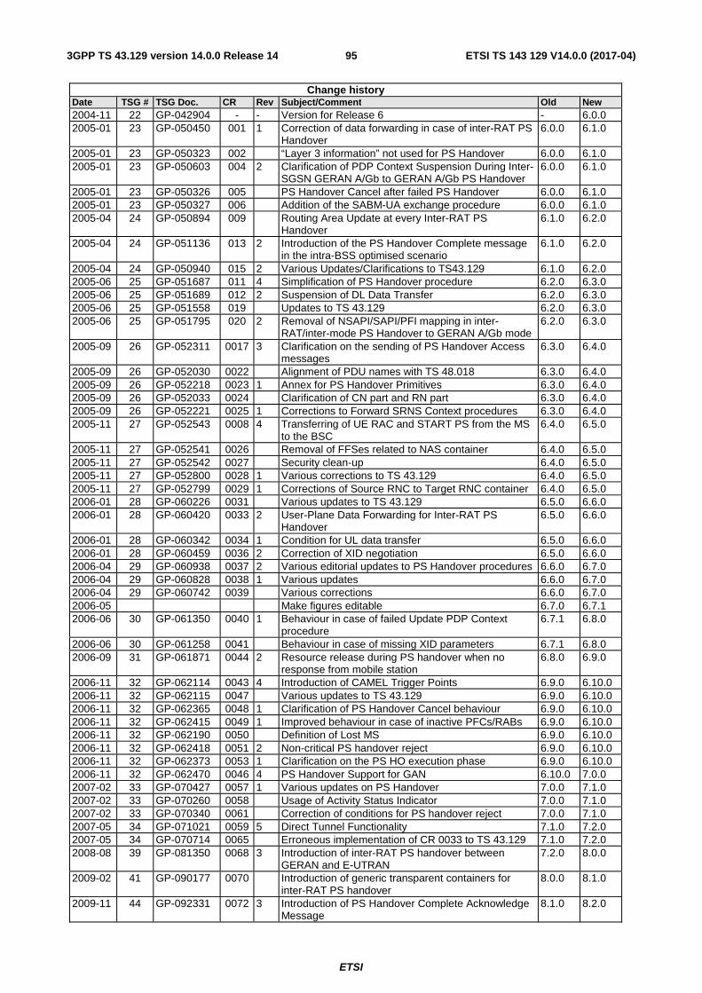
ETSI
ETSI TS 143 129 V14.0.0 (2017-04)953GPP TS 43.129 version 14.0.0 Release 14
Change history Date TSG # TSG Doc. CR Rev Subject/Comment Old New 2004-11 22 GP-042904 - - Version for Release 6 - 6.0.0 2005-01 23 GP-050450 001 1 Correction of data forwarding in case of inter-RAT PS
Handover 6.0.0 6.1.0
2005-01 23 GP-050323 002 “Layer 3 information” not used for PS Handover 6.0.0 6.1.0 2005-01 23 GP-050603 004 2 Clarification of PDP Context Suspension During Inter-
SGSN GERAN A/Gb to GERAN A/Gb PS Handover 6.0.0 6.1.0
2005-01 23 GP-050326 005 PS Handover Cancel after failed PS Handover 6.0.0 6.1.0 2005-01 23 GP-050327 006 Addition of the SABM-UA exchange procedure 6.0.0 6.1.0 2005-04 24 GP-050894 009 Routing Area Update at every Inter-RAT PS
Handover 6.1.0 6.2.0
2005-04 24 GP-051136 013 2 Introduction of the PS Handover Complete message in the intra-BSS optimised scenario
6.1.0 6.2.0
2005-04 24 GP-050940 015 2 Various Updates/Clarifications to TS43.129 6.1.0 6.2.0 2005-06 25 GP-051687 011 4 Simplification of PS Handover procedure 6.2.0 6.3.0 2005-06 25 GP-051689 012 2 Suspension of DL Data Transfer 6.2.0 6.3.0 2005-06 25 GP-051558 019 Updates to TS 43.129 6.2.0 6.3.0 2005-06 25 GP-051795 020 2 Removal of NSAPI/SAPI/PFI mapping in inter-
RAT/inter-mode PS Handover to GERAN A/Gb mode 6.2.0 6.3.0
2005-09 26 GP-052311 0017 3 Clarification on the sending of PS Handover Access messages
6.3.0 6.4.0
2005-09 26 GP-052030 0022 Alignment of PDU names with TS 48.018 6.3.0 6.4.0 2005-09 26 GP-052218 0023 1 Annex for PS Handover Primitives 6.3.0 6.4.0 2005-09 26 GP-052033 0024 Clarification of CN part and RN part 6.3.0 6.4.0 2005-09 26 GP-052221 0025 1 Corrections to Forward SRNS Context procedures 6.3.0 6.4.0 2005-11 27 GP-052543 0008 4 Transferring of UE RAC and START PS from the MS
to the BSC 6.4.0 6.5.0
2005-11 27 GP-052541 0026 Removal of FFSes related to NAS container 6.4.0 6.5.0 2005-11 27 GP-052542 0027 Security clean-up 6.4.0 6.5.0 2005-11 27 GP-052800 0028 1 Various corrections to TS 43.129 6.4.0 6.5.0 2005-11 27 GP-052799 0029 1 Corrections of Source RNC to Target RNC container 6.4.0 6.5.0 2006-01 28 GP-060226 0031 Various updates to TS 43.129 6.5.0 6.6.0 2006-01 28 GP-060420 0033 2 User-Plane Data Forwarding for Inter-RAT PS
Handover 6.5.0 6.6.0
2006-01 28 GP-060342 0034 1 Condition for UL data transfer 6.5.0 6.6.0 2006-01 28 GP-060459 0036 2 Correction of XID negotiation 6.5.0 6.6.0 2006-04 29 GP-060938 0037 2 Various editorial updates to PS Handover procedures 6.6.0 6.7.0 2006-04 29 GP-060828 0038 1 Various updates 6.6.0 6.7.0 2006-04 29 GP-060742 0039 Various corrections 6.6.0 6.7.0 2006-05 Make figures editable 6.7.0 6.7.1 2006-06 30 GP-061350 0040 1 Behaviour in case of failed Update PDP Context
procedure 6.7.1 6.8.0
2006-06 30 GP-061258 0041 Behaviour in case of missing XID parameters 6.7.1 6.8.0 2006-09 31 GP-061871 0044 2 Resource release during PS handover when no
response from mobile station 6.8.0 6.9.0
2006-11 32 GP-062114 0043 4 Introduction of CAMEL Trigger Points 6.9.0 6.10.0 2006-11 32 GP-062115 0047 Various updates to TS 43.129 6.9.0 6.10.0 2006-11 32 GP-062365 0048 1 Clarification of PS Handover Cancel behaviour 6.9.0 6.10.0 2006-11 32 GP-062415 0049 1 Improved behaviour in case of inactive PFCs/RABs 6.9.0 6.10.0 2006-11 32 GP-062190 0050 Definition of Lost MS 6.9.0 6.10.0 2006-11 32 GP-062418 0051 2 Non-critical PS handover reject 6.9.0 6.10.0 2006-11 32 GP-062373 0053 1 Clarification on the PS HO execution phase 6.9.0 6.10.0 2006-11 32 GP-062470 0046 4 PS Handover Support for GAN 6.10.0 7.0.0 2007-02 33 GP-070427 0057 1 Various updates on PS Handover 7.0.0 7.1.0 2007-02 33 GP-070260 0058 Usage of Activity Status Indicator 7.0.0 7.1.0 2007-02 33 GP-070340 0061 Correction of conditions for PS handover reject 7.0.0 7.1.0 2007-05 34 GP-071021 0059 5 Direct Tunnel Functionality 7.1.0 7.2.0 2007-05 34 GP-070714 0065 Erroneous implementation of CR 0033 to TS 43.129 7.1.0 7.2.0 2008-08 39 GP-081350 0068 3 Introduction of inter-RAT PS handover between
GERAN and E-UTRAN 7.2.0 8.0.0
2009-02 41 GP-090177 0070 Introduction of generic transparent containers for inter-RAT PS handover
8.0.0 8.1.0
2009-11 44 GP-092331 0072 3 Introduction of PS Handover Complete Acknowledge Message
8.1.0 8.2.0
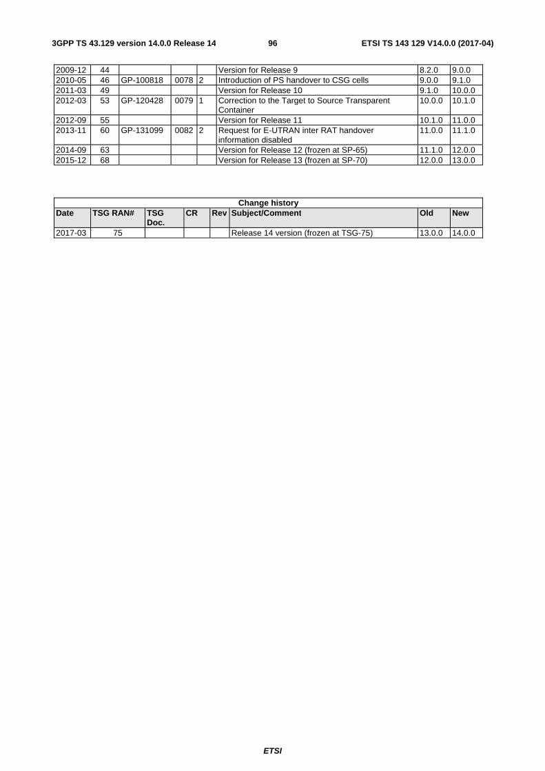
ETSI
ETSI TS 143 129 V14.0.0 (2017-04)963GPP TS 43.129 version 14.0.0 Release 14
2009-12 44 Version for Release 9 8.2.0 9.0.0 2010-05 46 GP-100818 0078 2 Introduction of PS handover to CSG cells 9.0.0 9.1.0 2011-03 49 Version for Release 10 9.1.0 10.0.0 2012-03 53 GP-120428 0079 1 Correction to the Target to Source Transparent
Container 10.0.0 10.1.0
2012-09 55 Version for Release 11 10.1.0 11.0.0 2013-11 60 GP-131099 0082 2 Request for E-UTRAN inter RAT handover
information disabled 11.0.0 11.1.0
2014-09 63 Version for Release 12 (frozen at SP-65) 11.1.0 12.0.0 2015-12 68 Version for Release 13 (frozen at SP-70) 12.0.0 13.0.0
Change history Date TSG RAN# TSG
Doc. CR Rev Subject/Comment Old New
2017-03 75 Release 14 version (frozen at TSG-75) 13.0.0 14.0.0

ETSI
ETSI TS 143 129 V14.0.0 (2017-04)973GPP TS 43.129 version 14.0.0 Release 14
History
Document history
V14.0.0 April 2017 Publication