Embed Size (px)
Citation preview

TS®220 and TS®250 Basic Rate ISDN Test Set
Network Support Division
next level solutions User’s GuideUser’s Guide
Technical Manual

ii
No part of this publication may be reproduced, stored on a retrieval system, or transmitted, in any form or by any means electronic, mechanical, photocopying, recording, or otherwise, without the prior written permission of Harris Corporation. The use of trademarks or other designations is for reference purposes only.
NOTICE
Harris Corporation makes no warranties about this document. Harris Corporation reserves the right to make hardware and software changes to the product described within this document without prior notice and without obligation to notify any person of such revision or change.
TRADEMARKS
TS is a registered trademark of Harris Corporation.
next level solutions
Network Support Division | 809 Calle Plano | Camarillo, CA 93012-8519 USA
www.harris.com 1-800-437-2266
©1997 Harris Corporation
Written/Printed in USA. 0II-724980-001, Issue 3, September 2000
iii
Contents
1. Introd uction 1-1
■ General Information 1-1
■ Basic Rate ISDN 1-1
■ Description 1-2
■ Design Features 1-2
■ Physical Characteristics 1-3
■ Specifications 1-4
2. Operation 2-1
■ Keypad 2-1
■ Numeric Keypad 2-1
■ Primary Function Keys 2-1
■ Soft Function Keys 2-3
■ Speaker Key 2-4
■ Mute Key 2-4
■ Indicators 2-5
■ Battery Indicator 2-5
■ LED Indicators 2-5
■ Sync LED 2-5
■ Charge LED 2-6
■ Voltage LED 2-6
■ Off Hook LED 2-7
■ Package Contents 2-7
■ Connections 2-8
■ Line Cord 2-8
■ Banjo Clip 2-8
■ Power Supply/Charging 2-8
■ Default Mode 2-9
■ Memory Dial 2-10
■ Last Number Redial 2-11
■ Speed Dial/Recall 2-11

iv
3. User Interface 3-1
■ Power On 3-1
■ Power On Self Test (POST) 3-1
■ Home Screen 3-2
■ Differentiating Between Voice/Data Calls 3-2
■ Identifying the Rate 3-3
■ Selecting the B Channel 3-4
■ Selecting the Switch Type 3-4
■ Assigning Service Profile Identifiers/Directory Number 3-5
■ NAT’L, DMS100, and 5ESS Multi Point Switches 3-5
■ 5ESS Point-to-Point Switch 3-7
■ Nat’L Auto SPID 3-8
■ Assigning Call Appearance Number 3-9
■ NAT’L, DMS100, and 5ESS Multi Point Switches 3-10
■ 5ESS Point-to-Point Switch 3-10
■ Assigning a Terminal Equipment Identifier (TEI) 3-10
■ NAT’L, DMS100, and 5ESS Multi Point Switches 3-11
■ 5ESS Point-to-Point Switch 3-12
■ Menu Key 3-12
■ Bit Error Rate Test (BERT) 3-13
■ Setting BERT Parameters in NT1+TE or TE Mode 3-13
■ Setting BERT Parameters in LT Mode 3-14
■ Making a Single BERT Test in NT1+TE or TE Mode 3-18
■ Making a BERT in LT Mode 3-20
■ Dual BERT Call Yourself 3-21
■ Layer 1 (NT1+TE and LT Mode) 3-23
■ NEBE/FEBE 3-23
■ 40 KHz Tone Generation 3-25
■ Embedded Operations Channel 3-26
■ EOC Address 3-29
■ Layer 1 (TE Mode) 3-30
■ Power Source 3-30
■ Q Channel 3-33
■ 96 KHz Tone Generation 3-34
■ Mode Selection 3-34
■ NT1+TE Mode 3-35
■ Line Termination (LT) Mode 3-35

v
■ TE Mode 3-35
■ Setting/Changing Modes 3-37
■ Centrex 3-38
■ View 3-39
■ NT1+TE or TE Mode 3-39
■ LT Mode 3-40
■ Options for Feature Adjustments 3-40
■ LCD Contrast Control 3-41
■ Receiver Volume Control 3-41
■ Auto Off 3-42
■ Ringer Volume 3-42
■ Audible Key Beep 3-43
■ Software Upgrade 3-43
■ Defaults 3-44
■ Auto Answer and Loopback 3-45
■ Dialing 3-45
■ Backlight 3-46
■ Recall (Speed Dial) Key 3-46
■ LNR Key 3-48
■ Assist Key 3-48
■ Selecting Topics Alphabetically 3-49
■ Cause Messages 3-50
■ Single Voice Call NT1+TE or TE Mode 3-53
■ Dry Loop/LT Mode Voice Call (Test Set to Test Set) 3-54
■ Dual Voice Call 3-55
■ NT Maintenance Mode (Quiet Mode/Insertion Loss) 3-57
4. X.25 4-1
■ Call Configuration 4-1
■ Preparing for an X.25 Call 4-2
■ Assigning a Directory Number 4-3
■ Assigning a Logical Channel Number 4-4
■ Assigning a Terminal Equipment Identifier (TEI) 4-4
■ Configuring a Call 4-5
■ Closed User Group 4-6
■ Reverse Charge 4-7

vi
■ User Data 4-7
■ Registered Private Operating Agency 4-9
■ Data Packet 4-9
■ Single D Packet Call 4-10
■ Originating a Call 4-11
■ Manual Dialing 4-11
■ Speed Dialing 4-11
■ Redial 4-12
■ Menu Key 4-12
■ Auto 4-13
■ View 4-14
■ Verifying an X.25 Line 4-15
■ Making a Self or Auto Call 4-16
■ Receiving an Incoming Call 4-19
■ Rejecting an Incoming Call 4-20
5. Maintenance 5-1
■ General Care 5-1
■ Line Cord 5-1
■ Keypad 5-1
■ Belt Clip 5-2
■ Battery 5-2
■ Safety Precautions 5-2
■ Charging the NiCad Batteries 5-3
■ Battery Replacement 5-4
■ Belt Clip Replacement 5-7
■ Line Cord Replacement 5-8
■ Removing the Line Cord 5-8
■ Line Cord Installation 5-10
■ Warranty 5-11
■ Return of Equipment 5-12

Introduction 1-1
1Introduction
General Information
This document provides the user with operating information for the TS220 and TS250 Basic Rate ISDN Test Set manufactured by Harris Corporation, Camarillo, California.
Basic Rate ISDN
The Basic Rate Test Set for Integrated Services Digital Network (ISDN) communication lines allows technicians and installers to verify functionality of an ISDN line without having to interpret complex ISDN protocols. The TS220 and TS250 Test Sets are a single solution for ISDN subscriber loop prequalification, installation, and maintenance.
The TS220 and TS250 Test Sets have three main modes of operation:
■ NT1+Terminal Equipment (NT1-TE, U Interface).
■ Line Termination (LT)/Dry Loop (U) (TS250 Model Only).
■ Terminal Equipment (TE, S/T Interface) Mode (TS250 Model Only).

1-2 Introduction
Description
The TS220 and TS250 Basic Rate ISDN Test Set (see Figure 1-1) is a compact, portable handset used by installers, repair technicians and other authorized personnel for testing of Basic Rate ISDN subscriber loops. The TS220 and TS250 Test Sets are battery or wall socket powered.
Figure 1-1. TS220 and TS250 Basic Rate ISDN Test Set
Design Features
Table 1-1 lists the TS220 and TS250 Test Set features.
Table 1-1. TS220 and TS250 Features
Features TS220 TS250
NT1-TE Mode for U Interface Testing ✔ ✔
TE Mode for S/T Interface Testing ✔
LT Mode/Dry Loop Mode Downstream Testing ✔
1B or 2B Channel Bit Error Rate Testing (BERT) ✔ ✔
FEBE/NEBE Testing ✔ ✔
Embedded Operations Channel Monitoring ✔ ✔
64K and 56K Data, Voice, and LAPD (X.25) Calls ✔ ✔
Amplified Speaker ✔ ✔
Transmitter Mute Switch ✔ ✔
bit2_016
LNR

Introduction 1-3
Table 1-1. TS220 and TS250 Features (Continued)
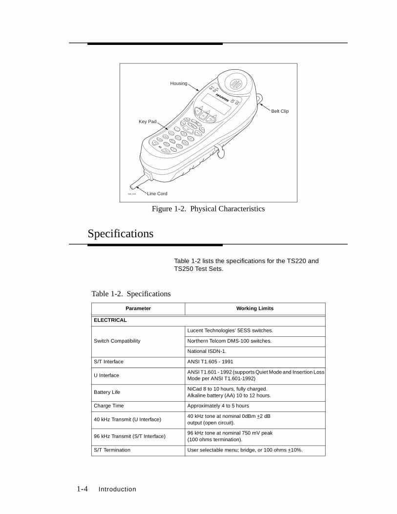
Physical Characteristics
The TS220 and TS250 Test Sets’ (see Figure 1-2) housing is made of high-impact plastic. The Test Sets are designed to provide rugged service and withstand the rough handling and shocks normally associated with field use. The housing is designed to permit operation of the Test Sets in bad weather (e.g., in heavy rain and dust storms).
The belt clip is located on the receiver end of the housing and is equipped with a spring-loaded clip that assures a secure connection to belt loops and D-rings.
The line cord is attached to the TS220 and TS250 Test Sets through a rubber strain relief at the transmitter end of the unit.
The line cord has either:
■ An angled bed-of-nails cord and a RJ-45 modular connector.
■ A 346A plug.
Features TS220 TS250
40 kHz Tone Generation (U interface) ✔ ✔
96 kHz Tone Generation (S/T interface) ✔
On-Line Assist Key Explaining Complex Messages in Plain English ✔ ✔
20 Location, 19 Digit Repertory Dialer ✔ ✔
Last Number Redial ✔ ✔
Backlit Liquid Crystal Display (LCD) ✔ ✔
Backlit Keypad ✔ ✔
Software Upgradeable ✔
Impact Resistant and Water Resistant with No-Fog Display ✔ ✔
Low Battery Indication ✔ ✔
Operates on 4 AA Alkaline, rechargeable NiCad batteries, or 120 Vac (adaptor included) ✔ ✔
Field Replaceable Line Cord and Batteries ✔ ✔
Field Replaceable Spring-Loaded Belt Clip ✔ ✔
Automated Call Yourself BERT ✔ ✔
1-4 Introduction
Figure 1-2. Physical Characteristics
Specifications
Table 1-2 lists the specifications for the TS220 and TS250 Test Sets.
Table 1-2. Specifications
Parameter Working Limits
ELECTRICAL
Switch Compatibility
Lucent Technologies’ 5ESS switches.
Northern Telcom DMS-100 switches.
National ISDN-1.
S/T Interface ANSI T1.605 - 1991
U InterfaceANSI T1.601 - 1992 (supports Quiet Mode and Insertion Loss Mode per ANSI T1.601-1992)
Battery Life NiCad 8 to 10 hours, fully charged. Alkaline battery (AA) 10 to 12 hours.
Charge Time Approximately 4 to 5 hours
40 kHz Transmit (U Interface)40 kHz tone at nominal 0dBm +2 dB output (open circuit).
96 kHz Transmit (S/T Interface)96 kHz tone at nominal 750 mV peak (100 ohms termination).
S/T Termination User selectable menu; bridge, or 100 ohms +10%.
bit2_019 Line Cord
Key Pad
Housing
Belt Clip
LNR

Introduction 1-5
Table 1-2. Specifications (Continued)
RS-232 SPECIFICATIONS
Baud Rate 9600, 19200
Data Bit 8 bits
Parity None
Stop Bits 1
Active Pin Assignments (DB9)2 - Receive3 - Transmit7 - Ground
PHYSICAL
Length 10 inches
Width 3-3/4 inches
Height 4-1/4 inches
Weight 2-1/2 pounds
ENVIRONMENTAL
Water ResistanceTS220 and TS250 Test Sets are designed to be rain and moisture resistant under conditions of inclement weather.
TemperatureOperatingStorage
0° to +50°C -20° to +70°C
Relative Humidity Noncondensing.
Drop Designed not to exceed 12 foot drop.
Note: Specifications subject to change without notice.
Operation 2-1
2Operation
Keypad
Numeric Keypad
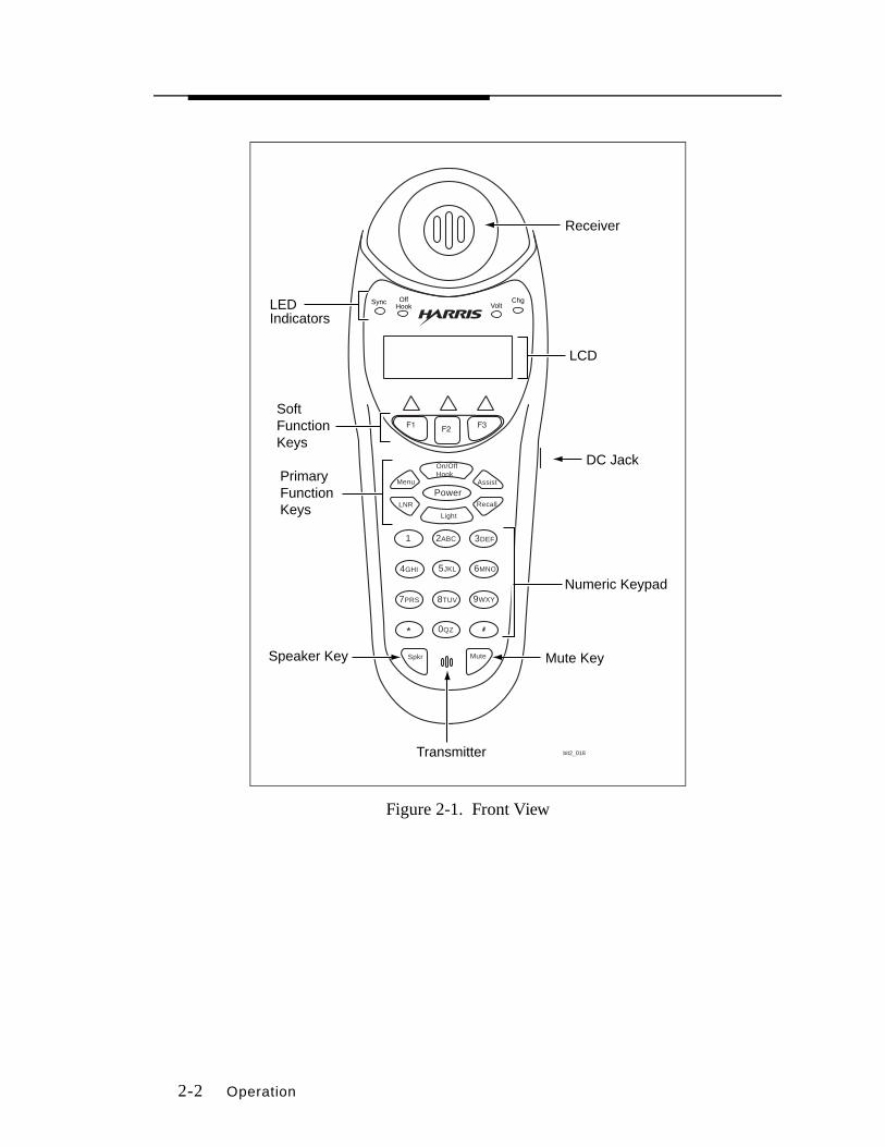
The numeric keypad (see Figure 2-1) is used to dial telephone numbers and make menu selections. The numeric keypad includes 12 standard dialing keys including the asterisk (❋) and the pound (#) keys.
Primary Function Keys
The primary function keys are:
■ Power
Allows the user to apply power to, and remove power from the test set. The Power key is recessed to avoid accidental power down. To turn the Test Set off, press and hold the Power key. Unless Auto Power Down is disabled, or the test set is powered by the AC adapter, the TS220 and TS250 Test Sets automatically power down after 5 minutes, if no activity is detected.
2-2 Operation
Figure 2-1. Front View
Numeric Keypad
PrimaryFunctionKeys
Sync OffHook Volt
ChgLEDIndicators
Receiver
Mute KeySpeaker Key
SoftFunctionKeys
Transmitter
DC Jack
LCD
bit2_018
2ABC1 3DEF
4GHI 5JKL 6MNO
7PRS 8TUV 9WXY
0QZ
LNR
Menu
On/OffHook
Assist
Power
Light
Recall
Spkr Mute
Operation 2-3
■ On/Off Hook
Press once to initiate or answer a call. Press again to terminate a call.
■ Light
Press the Light key to backlight the menu display (LCD) and the keypad for easier viewing in dark areas. Press the Light key again to turn the backlight off. Unless the backlight timeout is changed, the backlight turns off automatically if the keypad isn’t used for a period of 30 seconds, and test set is operating off of battery power.
■ Assist
During operation, pressing the Assist key will present relevant information on the LCD for explaining the selected menu item (e.g., SPIDs, Rate, Call, etc). Pressing the Assist key twice allows the user to enter a number and jump alphabetically to all relevant information on the topic in the Test Set (e.g., press the number 2 twice to go to all topics beginning with the letter B); or scroll alphabetically through the list of topics.
The Assist key will also allow the user to view the definition of cause messages.
■ Menu
Provides a menu of functions which are then selectable using the numeric keys. The Menu stays on the display until either a menu function is selected, or the Menu key is pressed again, thereby returning to the previous display.
■ LNR
Allows the user to redial the last number dialed.
■ Recall
Recalls a number stored in repertory dialer memory.
Soft Function Keys
The three soft function keys are located below the LCD and their function changes depending on the context on the display. The three soft keys are labeled F1, F2, and F3 (see Figure 2-1).

2-4 Operation
Speaker Key
Note: Transmitter is automatically muted when speaker is on.
Pressing the Speaker Key on the TS220 and TS250 Test Sets changes the amplified speaker volume to its next setting, and all signals heard through the receiver are routed to the speaker. The user may set the volume level of the amplified speaker to either off, low, or high. Settings change from off to low to high and back to off.
The Amplified Speaker icon (see Figure 2-2) is displayed on the LCD any time the speaker is active, regardless of the specific volume setting.
When low battery is detected, the speaker is automatically disabled.
Figure 2-2. Amplified Speaker Icons
Mute Key
The Mute key is used as a toggle to activate or deactivate the muting of the transmitter. The active mute condition is indicated to the user by displaying the Mute icon (see Figure 2-3).
Figure 2-3. Mute Icon
High Low

Operation 2-5
Indicators
Battery Indicator
A low battery condition is indicated to the user through the use of a low battery icon on the LCD (see Figure 2-4). A flashing icon indicates the test set has reached its first warning level. When the Low Battery icon appears on the LCD display, you have approximately 30 minutes of operating time left before the test set automatically powers off. The second level occurs when the icon is solid. At this level, the test set is not functional. Refer to Maintenance for more information on low battery condition.
Figure 2-4. Low Battery Icon
LED Indicators
The LED indicators (see Figure 2-1) are located above the LCD Menu display window. See Table 2-1 for indication status.
Sync LED U Interface - The U (basic rate) interface refers to the physical interface on the network side of a network termination 1 (NT1). When Layer 1 is in SYNC, the SYNC LED indicator blinks amber. When Layer 1 activation is complete and the U interface is activated, the SYNC LED indicator lights up a solid amber. When Layers 2 and 3 are ready, the SYNC LED indicator lights up green.
S/T Interface (TS250 only) - The S/T interface is a two-pair (four wire) interface between the terminal equipment (TE) and a NT1. When Layer 1 is in SYNC, the SYNC LED blinks amber. When Layer 1 activation is complete and S/T is sychronized, the SYNC LED indicator lights up amber. When Layers 2 and 3 are ready, the SYNC LED indicator lights up green.

2-6 Operation
Charge LED The charging LED indicates the battery is currently in charge mode. An amber LED indicates the unit is in fast charge (approximately 4 to 5 hours, if battery is completely dead). After fast charge, the TS220 and TS250 Test Sets will remain in trickle charge indicated by a green LED. When the LED is off, the battery is not being charged.
Voltage LED Voltage LED illuminates automatically to indicate the presence of sealing current. If there is no sealing current on the line or the TS220 or TS250 Test Set is not connected to the line, the voltage LED is not lit.
U Interface - The LED will light green if sealing current is present across tip or ring.
S/T Interface (TS250 only) - In S/T mode the Voltage LED can be programmed to indicate a single power source or a combination of power sources (see Section 3, Layer 1 (TE Mode) for more information).
Table 2-1. LED Status Indicators
LED LED Color Description
HOOK OFF On Hook
Green Blinking Off hook, waiting for SYNC and activation.
Green Solid Off hook.
SYNC OFF No Layer 1 communication.
Amber Blinking Layer 1 SYNC.
Amber Solid Activation complete.
Green Layer 1, 2 and 3 SYNC.
CHARGE OFF Running on battery.
Amber Fast charge.
Green Trickle charge.
VOLTAGEU INTERFACE
OFF Sealing current not present.
GREEN Sealing current present.
VOLTAGE S/T INTERFACE*
OFF No PS1, PS2, PS3 present.
Green Normal polarity (see Section 3, Layer 1 [TE Mode]).
Red Reverse polarity (see Section 3, Layer 1 [TE Mode]).
Note: *TS250 only.
Operation 2-7
Off Hook LED When the unit is taken off hook and layer 3 communication is established, the off hook LED lights green and is on continuously. If no Layer 3 SYNC is established, the LED will blink green.
During times when activation and synchronization of network elements are in progress and the unit is off hook, the off hook LED blinks on and off until such time as dial tone can be provided to indicate to the user that dialing may now proceed.
When the unit is placed on hook, the LED is extinguished.
Package Contents
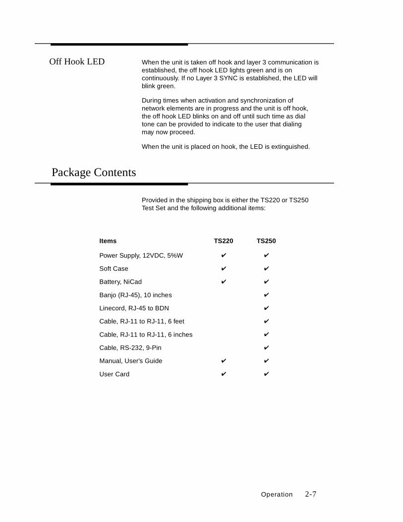
Provided in the shipping box is either the TS220 or TS250 Test Set and the following additional items:
Items TS220 TS250
Power Supply, 12VDC, 5%W ✔ ✔
Soft Case ✔ ✔
Battery, NiCad ✔ ✔
Banjo (RJ-45), 10 inches ✔
Linecord, RJ-45 to BDN ✔
Cable, RJ-11 to RJ-11, 6 feet ✔
Cable, RJ-11 to RJ-11, 6 inches ✔
Cable, RS-232, 9-Pin ✔
Manual, User’s Guide ✔ ✔
User Card ✔ ✔
2-8 Operation
Connections
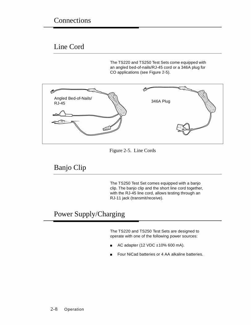
Line Cord
The TS220 and TS250 Test Sets come equipped with an angled bed-of-nails/RJ-45 cord or a 346A plug for CO applications (see Figure 2-5).
Figure 2-5. Line Cords
Banjo Clip
The TS250 Test Set comes equipped with a banjo clip. The banjo clip and the short line cord together, with the RJ-45 line cord, allows testing through an RJ-11 jack (transmit/receive).
Power Supply/Charging
The TS220 and TS250 Test Sets are designed to operate with one of the following power sources:
■ AC adapter (12 VDC ±10% 600 mA).
■ Four NiCad batteries or 4 AA alkaline batteries.
346A PlugAngled Bed-of-Nails/RJ-45

Operation 2-9
When an AC adapter is used, the batteries are automatically disconnected; if NiCad batteries are installed the charging process will begin. The TS220 and TS250 Test Sets, when using an AC adapter and power is turned on, receives power from the AC adapter and does not affect the battery charging process.
The charge (Chg) indicator will display amber during fast charge (4 to 5 hours to charge when batteries are completely dead). When fast charge is complete, the test set switches to trickle charge (green indicator) and is ready for use (fully charged). The Test Set will remain in trickle charge until the charger (DC power) is removed.
The NiCad batteries should be charged for 4 to 5 hours before first use of the TS220 or TS250 Test Set. When fully charged, the NiCad battery pack can power the Test Set for 8 to 10 hours of continuous operation.
Default Mode
The Test Set will default to the last mode selected by the user (e.g., NT, LT, or TE mode).
Table 2-2 shows the default settings for the Test Set when powered on for the first time.
Table 2-2. Factory Default Settings
Setting
BERT Rate 56K
BERT Time 3:00 minutes
Call Appearance 1
ISDN Mode NT1+TE
Receiver Volume Medium
Switch Type National ISDN-1
Terminal Equipment Identifier (TEI) Auto (127)
Contrast Setting 4
Auto Off Enable
Key Beep Enable
Ringer Low
2-10 Operation
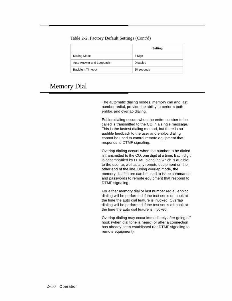
Table 2-2. Factory Default Settings (Cont’d)
Memory Dial
The automatic dialing modes, memory dial and last number redial, provide the ability to perform both enbloc and overlap dialing.
Enbloc dialing occurs when the entire number to be called is transmitted to the CO in a single message. This is the fastest dialing method, but there is no audible feedback to the user and enbloc dialing cannot be used to control remote equipment that responds to DTMF signaling.
Overlap dialing occurs when the number to be dialed is transmitted to the CO, one digit at a time. Each digit is accompanied by DTMF signaling which is audible to the user as well as any remote equipment on the other end of the line. Using overlap mode, the memory dial feature can be used to issue commands and passwords to remote equipment that respond to DTMF signaling.
For either memory dial or last number redial, enbloc dialing will be performed if the test set is on hook at the time the auto dial feature is invoked. Overlap dialing will be performed if the test set is off hook at the time the auto dial feaure is invoked.
Overlap dialing may occur immediately after going off hook (when dial tone is heard) or after a connection has already been established (for DTMF signaling to remote equipment).
Setting
Dialing Mode 7 Digit
Auto Answer and Loopback Disabled
Backlight Timeout 30 seconds

Operation 2-11
Last Number Redial
The last number dialed may be recalled by pressing the Last Number Redial (LNR) key. The last number dialed is displayed on the screen as it is dialed. The last number dialed may be recalled even after powering down the unit. The redial memory has a 20-digit capacity.
Speed Dial/Recall
Pressing the speed Recall key (see Figure 2-6) followed by the memory address (01 to 20) will automatically dial the contents of that particular address. Each memory address, up to 20 digits in length, can be stored.
Speed dial numbers may be used for phone numbers, DTMF commands for automated equipment passwords, etc.
Figure 2-6. Recall Screen
Enter 01-20 to Dial.Scroll to View/Edit.
Back Fwd Exit
NT
User Interface 3-1
3User Interface
Power On
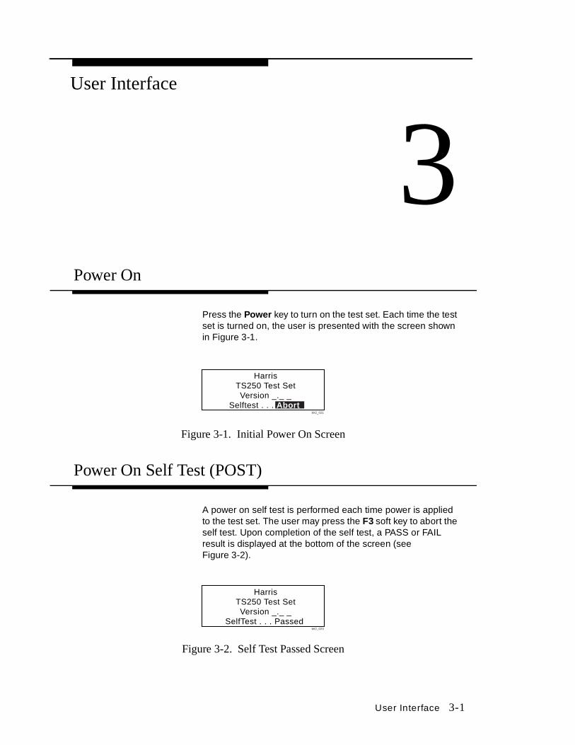
Press the Power key to turn on the test set. Each time the test set is turned on, the user is presented with the screen shown in Figure 3-1.
Figure 3-1. Initial Power On Screen
Power On Self Test (POST)
A power on self test is performed each time power is applied to the test set. The user may press the F3 soft key to abort the self test. Upon completion of the self test, a PASS or FAIL result is displayed at the bottom of the screen (see Figure 3-2).
Figure 3-2. Self Test Passed Screen
HarrisTS250 Test SetVersion _._ _
Selftest . . . Abort bit2_021
HarrisTS250 Test SetVersion _._ _
SelfTest . . . Passed bit2_020

3-2 User Interface
If the self test fails, a message indicating the cause of the failure will appear at the bottom of the screen. The user then has the option to abort or continue with the self test.
Home Screen
The Home Screen (see Figure 3-3) is used to set or change a call configuration description. The Home Screen is displayed after powering on the unit.
Figure 3-3. Home Screen
From the Home Screen, the user can:
■ Make changes to the call, bearer capability, and selection of outgoing B Channel.
■ Change the switch type.
■ Assign a Service Profile Identifier (SPID) or a Directory Number (DN).
Differentiating Between Voice/Data Calls
There are three types of calls supported (data, voice, and X.25 LAPD [see Section 4]). Two B Channels support voice and data calls. Call A and Call B can be reserved for either voice or data on either B channel.
1. At the Home Screen (see Figure 3-3), press F1 to select Call. The Call Selection Screen (see Figure 3-4) is displayed. From this screen, changes and settings can be made to the call type, rate, and B Channel.
Call: A 5ESS PPDN: 5552000B1: Voice B2: Voice
Call Switch DN
NT
bit2_141
Call: A 5ESS MPSPID: 0555200001B1:64K B2:VoiceCall Switch SPID
NT
bit2_137
Home Screen for NAT’L, DMS100, 5ESS Multi Point Switches, and Auto SPID
Home Screen for 5ESS Point-To-Point Switches

User Interface 3-3
2. Press either:
a. 1 to select Call A as the active call.
b. 4 to select Call B as the active call.
c. 7 to select x.25 D packet calls.
Figure 3-4. Call Selection Screen
3. Press F3 to return to the previous screen.
Identifying the Rate
The Rate Selection Screen allows the user to tell the switch equipment the rate at which it is going to transmit (e.g., 56K, 64K, or voice). Some older lines are provisioned with connections that can only support 56K.
To identify the transmission rate:
1. At the Call Selection Screen (see Figure 3-4), press F1 to select Rate. The Rate Selection Screen is displayed (see Figure 3-5).
Figure 3-5. Rate Selection Screen
2. Press either 1, 4, or 7, and either 2, 5, or 8.
3. Press F3 to return to the previous screen.
1-Select Call A4-Select Call B7-Select X.25 D Pkt
PrevRate B Chan
NT
bit2_163
Voice 1-B1 2-B264K 4-B1 5-B256K 7-B1 8-B2
Prev
NT
bit2_024

3-4 User Interface
Selecting the B Channel
There are two Bearer (B) Channels (B1 and B2) over which you can make or receive a call. You can either select the channel or you can let the switch equipment select the channel for you.
To select or change the B Channel used for outgoing calls:
1. At the Call Selection Screen (see Figure 3-4), press F2 to select B Chan. The B Channel Selection Screen is displayed (see Figure 3-6).
Figure 3-6. B Channel Selection Screen
2. Press 1, 4, or 7 to select channel allocation for Call A and Call B.
3. Press F3 to return to the previous screen.
Selecting the Switch Type
To select or change the switch type:
1. At the Home Screen (see Figure 3-3), press F2 to select Switch. The Switch Selection Screen is displayed (see Figure 3-7). From this screen, the switch type can be changed.
Figure 3-7. Switch Selection Screen
Call A Call B1-B1 B24-B2 B17-Any Any
N
Prev
T
bit2_026
1-NAT'L 2-5ESS MP4-DMS100 5-5ESS PP7-NAT'L Auto SPID
Prev
NT
bit2_025
User Interface 3-5
2. Press 1, 2, 4, 5, or 7. A checkmark will be entered next to the desired switch type.
3. Press F3 to return to the previous screen.
4. When the Home Screen (see Figure 3-3) is displayed, verify that the correct switch information is displayed. If the information is incorrect, correct the information in accordance with the procedures in this manual.
Assigning Service Profile Identifiers/Directory Number
Note: A SPID is not used on a 5ESS Point-to-Point (PP) Switch and therefore SPID is not displayed on the Home Screen (see Figure 3-3).
The user may assign up to two SPIDs to the test set. One SPID can be assigned to Call A and one to Call B. In some cases, a line may only be provisioned for a single SPID. If the line is provisioned for a single SPID, the test set must be set up for a single SPID. If not set up properly, the user may be unable to initiate or receive a call.
The user may assign up to two Directory Numbers (DN) to the test set. Each DN will identify the telephone number associated with each call (Call A or Call B). The DN can only be entered or changed after the SPID has been assigned. The test will attempt to derive the DN from the SPID. The user can verify if the DN is correct through the DN menu.
NAT’L, DMS100, and 5ESS Multi Point Switches
To assign a SPID to a NAT’L, DMS100, or 5ESS Multi Point (MP) switch:
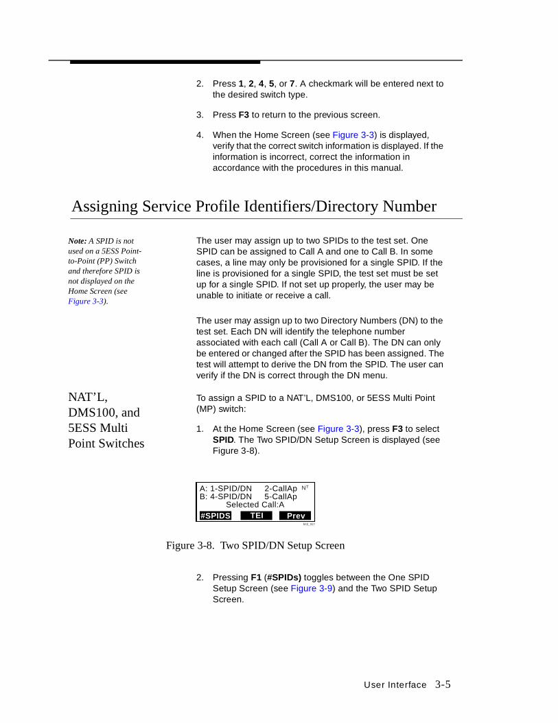
1. At the Home Screen (see Figure 3-3), press F3 to select SPID. The Two SPID/DN Setup Screen is displayed (see Figure 3-8).
Figure 3-8. Two SPID/DN Setup Screen
2. Pressing F1 (#SPIDs) toggles between the One SPID Setup Screen (see Figure 3-9) and the Two SPID Setup Screen.
A: 1-SPID/DN 2-CallApB: 4-SPID/DN 5-CallAp
Selected Call:A#SPIDS TEI Prev
NT
bit2_027

3-6 User Interface
Figure 3-9. One SPID/DN Setup Screen
3. If the Two SPID/DN Setup Screen is selected, press 1 or 4 to edit the SPID/DN. The Edit SPID screen is displayed (see Figure 3-10).
4. If the One SPID/DN Setup Screen is selected, press 1 to edit the SPID. The Edit SPID screen is displayed (see Figure 3-10).
Figure 3-10. Edit SPID Screen
5. Press F2 to select <BkSp to delete SPID shown on display. The cursor moves backward to delete the existing SPID. Press and hold <BkSp to delete multiple digits.
6. Enter the new SPID and press F1 to Send. One of the following messages will appear:
a. Sending SPID.
b. Resending SPID.
c. SPID A registered.
d. SPID A failed.
e. SPID B registered.
f. SPID B failed.
g. SPIDs must be unique.
Note: In most cases, once a SPID is entered, you don’ t have to enter DN number.
7. If the SPID has registered, the user can then press F3 to select Save and go to the DN Edit Screen (see Figure 3-11).
1-SPID/DN 2-CallAp
Prev#SPIDs TEI
NT
Selected Call: A
Edit SPID, Call A:8057380478010_SPID Status Messages
NT
BkSpSend Savebit2_038
User Interface 3-7
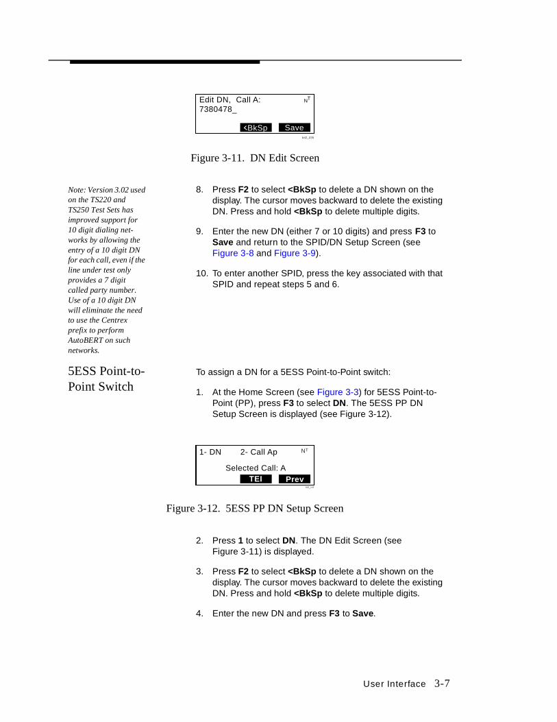
Figure 3-11. DN Edit Screen
Note: Version 3.02 used on the TS220 and TS250 Test Sets has improved support for 10 digit dialing net-works by allowing the entry of a 10 digit DN for each call, even if the line under test only provides a 7 digit called party number. Use of a 10 digit DN will eliminate the need to use the Centrex prefix to perform AutoBERT on such networks.
8. Press F2 to select <BkSp to delete a DN shown on the display. The cursor moves backward to delete the existing DN. Press and hold <BkSp to delete multiple digits.
9. Enter the new DN (either 7 or 10 digits) and press F3 to Save and return to the SPID/DN Setup Screen (see Figure 3-8 and Figure 3-9).
10. To enter another SPID, press the key associated with that SPID and repeat steps 5 and 6.
5ESS Point-to-Point Switch
To assign a DN for a 5ESS Point-to-Point switch:
1. At the Home Screen (see Figure 3-3) for 5ESS Point-to-Point (PP), press F3 to select DN. The 5ESS PP DN Setup Screen is displayed (see Figure 3-12).
Figure 3-12. 5ESS PP DN Setup Screen
2. Press 1 to select DN. The DN Edit Screen (see Figure 3-11) is displayed.
3. Press F2 to select <BkSp to delete a DN shown on the display. The cursor moves backward to delete the existing DN. Press and hold <BkSp to delete multiple digits.
4. Enter the new DN and press F3 to Save.
Edit DN, Call A:7380478_
NT
BkSp Savebit2_035
1- DN 2- Call Ap
Selected Call: ATEI Prev
NT
bit2_142

3-8 User Interface
Nat’L Auto SPID
The AutoSPID feature sends an inquiry to the switch and if the switch supports AutoSPID then the switch will return the SPID to the test set and the test set will register the SPID. AutoSPID works only on lines which originate in a CO that supports AutoSPID. To determine if you have an Auto SPID:
1. At the Home Screen (see Figure 3-3), press F2 to select Switch. The Switch Selection Screen is displayed (see Figure 3-7).
2. At the Switch Selection Screen, press 7 to select NAT’L AutoSPID. A checkmark is placed by the entry.
3. Press F3 to return to the previous screen.
4. Wait for Sync (solid amber light is displayed under Sync above LCD). The AutoSPID Processing Screen is displayed (see Figure 3-13).
Figure 3-13. AutoSPID Processing Screen
5. If the switch is set up for AutoSPID, the AutoSPID Screen is displayed (see Figure 3-14) showing the SPID, and the Sync light will turn green.
Figure 3-14. AutoSPID Screen
6. If the switch does not support AutoSPID, the AutoSPID Failed Screen is displayed (see Figure 3-15).
Call:B Nat'l AutoSPID: Auto in ProsB2: Voice
Call Switch SPIDbit2_215
NT
Call:B Nat'l AutoSPID: 80055512120101B2: VoiceCall Switch SPID
bit2_222
NT

User Interface 3-9
Figure 3-15. AutoSPID Failed Screen
7. If the switch does not show an AutoSPID, it will be necessary to assign a SPID. Refer to Assigning Service Profile Identifiers/Director Number for instructions on how to assign a SPID.
8. While in AutoSPID, if you try to manually change the SPID, the test set will notify you that any SPID changes will deselect the AutoSPID feature and asks whether you want to accept the change or not. The SPID Changed Screen is displayed (see Figure 3-16).
Figure 3-16. SPID Changed Screen
9. If you press F1 for Yes, the Edit DN Screen is displayed (see Figure 3-11). Refer to Assigning Service Profile Identifiers/Director Number for instructions on how to change a DN.
10. If you press F2 for No, the Two SPID/DN Setup Screen (see Figure 3-8) or the One SPID/DN Setup Screen (see Figure 3-9) is displayed.
Assigning Call Appearance Number
For any voice call there is a call appearance number, which must be assigned. A call appearance value of 1 is usually accepted by most switches. Some lines are provisioned with a limited range of values that will be accepted. Setting call appearance allows the user to pick a value that is in the range that will be accepted by the switching equipment.
Call:B Nat'l AutoSPID: AutoSPID FailedB2: VoiceCall Switch SPID
bit2_220
NT
No
NT
bit2_221
SPID changes willdeselect AutoSPID.Accept changes?
Yes

3-10 User Interface
NAT’L, DMS100, and 5ESS Multi Point Switches
To assign the call appearance number for a NAT’L, DMS100, or a 5ESS MP switch:
1. At the Home Screen (see Figure 3-3), press F3 to select SPID. The SPID Setup Screen is displayed (see Figure 3-8 or Figure 3-9).
2. Press 2 or 5 to select CallAp. The Call Appearance Edit Screen is displayed (see Figure 3-17).
Figure 3-17. Call Appearance Edit Screen
Note: Call Appearance must be between 1 and 127.
3. Press F2 to select <BkSp to delete the call appearance number shown on the display. The cursor moves backward to delete the existing number.
4. Enter number and press F3 to select Save.
5ESS Point-to-Point Switch
To assign the call appearance number for a 5ESS PP switch:
1. At the Home Screen (see Figure 3-3) for 5ESS PP, press F3 to select DN. The 5ESS PP DN Setup Screen is displayed (see Figure 3-12).
2. Press 2 to select CallAp. The Call Appearance Edit Screen is displayed (see Figure 3-17).
Note: Call Appearance must be between 1 and 127.
3. Press F2 to select <BkSp to delete the call appearance number shown on the display. The cursor moves backward to delete the existing number.
4. Enter number and press F3 to select Save.
Assigning a Terminal Equipment Identifier (TEI)
The TEI may automatically be assigned by the CO or the user could request a specific TEI. Two TEIs may be required, one for each SPID. Working on lines with fixed TEIs may require that a TEI be manually entered.
Call Appearance A:127_ CA must be 1-127
SaveBkSp
NT
bit2-034

User Interface 3-11
NAT’L, DMS100, and 5ESS Multi Point Switches
To enter a TEI for a NAT’L, DMS100, or a 5ESS MP switch:
1. At the SPID Setup Screen (see Figure 3-8 or Figure 3-9), press F2 to select TEI. Either the One Call TEI Setup Screen (see Figure 3-18) or the Two Call TEI Setup Screen (see Figure 3-19) is displayed.
Figure 3-18. One Call TEI Setup Screen
Figure 3-19. Two Call TEI Setup Screen
2. Press 1 to edit the TEI for Call A. The TEI Edit Screen is displayed (see Figure 3-20).
Figure 3-20. TEI Edit Screen
3. Press F1 to select Auto. Auto will set the TEI to 127 (the numerical value for a broadcast TEI) and return you to the previous menu.
4. To delete a TEI, press F2 to select <BkSp. The cursor moves backward to delete the existing TEI.
Note: Only fixed TEI values between 0 and 63 are valid in this switch.
5. Enter the TEI number and press F3 to select Save.
6. To enter the TEI for Call B, press 4 and repeat Steps 3 through 5.
1-TEI = 127
Selected Call:APrev
NT
bit2_117
1-TEI Call A = 1274-TEI Call B = 127 Selected Call:A
Prev
NT
TEI Call A:127_ 0-63 are valid Auto BkSp Save
NT
bit2_072

3-12 User Interface
5ESS Point-to-Point Switch
To enter a TEI for a 5ESS PP switch:
1. At the Home Screen (see Figure 3-3) for 5ESS PP, press F3 to select DN. The 5ESS PP DN Setup Screen is displayed (see Figure 3-12).
2. Press F2 to select TEI. The One Call TEI Setup Screen (see Figure 3-18) is displayed.
3. Press 1 to edit the TEI. The TEI Edit Screen is displayed (see Figure 3-20).
4. Press F1 to select Auto. Auto will set the TEI to 127 (the numerical value for a broadcast TEI) and return you to the previous menu.
5. To delete a TEI, press F2 to select <BkSp. The cursor moves backward to delete the existing TEI.
6. Enter the TEI number and press F3 to select Save.
7. Press F3 to return to the previous menu.
Menu Key
Note: The TS220 Test Set does not have * - Mode.
The Menu key is used to bring up the Main Menu Screen. Press the Menu key to gain access to the Main Menu Screen (see Figure 3-21 and Figure 3-22).
Figure 3-21. Main Menu Screen (NT1+TE and TE Mode)
Figure 3-22. Main Menu Screen (LT Mode) (TS250 Only)
1-BERT4-Auto7-View
*- Mode
2-Layer 15-Options8-Centrex
Exit
NT
bit2_040
1-BERT4-Auto7-View
*- Mode
2-Layer 15-Options
Exit
LT
bit2_116

User Interface 3-13
The Main Menu Screen allows the user to:
■ Perform a BERT test (auto).
■ View/send Layer 1 commands.
■ View U Interface (EOC, NEBE/FEBE).
■ View S/T Interface (Q Channel, Power Source) (TS250 only).
■ View status (BERT, Call A/B, software version).
■ Change modes (TS250 only).
■ Perform automatic functions.
■ Make adjustments to the following options: LCD Contrast Control, Receiver Volume Control, Ringer Control, Defaults, or install a software upgrade (TS250 only).
■ Centrex features.
Bit Error Rate Test (BERT)
BERT allows the user to identify the number of bit errors to the total number of bits being sent in the data transmission from one location to another. The bit rate (BR) is the number of bits transferred in a given time interval. Bits per second is a measure of the rate at which bits are transmitted.
Setting BERT Parameters in NT1+TE or TE Mode
To set BERT parameters for NT1+TE or TE Mode:
1. Verify the correct mode (NT1+TE or TE Mode) has been selected. If not, select the correct mode (see Mode Selection for further information).
2. At the Main Menu Screen (see Figure 3-21), press 1 to select BERT. The BERT Screen for NT1+TE or TE Mode is displayed (see Figure 3-23).
Figure 3-23. BERT Screen
64K BERT B1Duration 03:00
NT
Start PrevSetupbit2_041

3-14 User Interface
3. To make changes to BERT parameters, press F1 to select Setup. The BERT Setup Screen for NT1+TE or TE Mode is displayed (see Figure 3-24).
Figure 3-24. BERT Setup Screen (NT1+TE or TE Mode)
4. Press 1 or 4 to select the rate (64K or 56K) at which BERT will be run.
5. To set the length of time to execute BERT, press F1 to select Time. The BERT Time Screen for NT1+TE or TE Mode is displayed (see Figure 3-25).
Figure 3-25. BERT Time Screen
6. Press F2 to select Clear, then enter time for BERT.
7. Press F3 to select Save and return to the previous screen.
Setting BERT Parameters in LT Mode
There are two basic applications for LT mode:
■ The test set has the capability of requesting loopback from a generic NT1 (see Figure 3-26). When a Loopback Test is requested, the unit can then perform a 1B or 2B BERT.
1-64K BERT4-56K BERT
NT
Time Prevbit2-073
Set BERT Time00:03:00
SaveClear
NT
bit2-083
User Interface 3-15
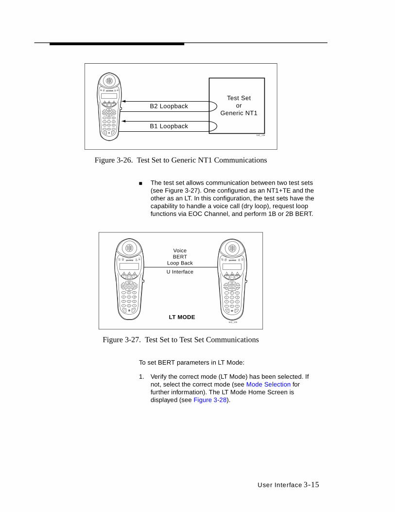
Figure 3-26. Test Set to Generic NT1 Communications
■ The test set allows communication between two test sets (see Figure 3-27). One configured as an NT1+TE and the other as an LT. In this configuration, the test sets have the capability to handle a voice call (dry loop), request loop functions via EOC Channel, and perform 1B or 2B BERT.
Figure 3-27. Test Set to Test Set Communications
To set BERT parameters in LT Mode:
1. Verify the correct mode (LT Mode) has been selected. If not, select the correct mode (see Mode Selection for further information). The LT Mode Home Screen is displayed (see Figure 3-28).
Test Setor
Generic NT1
B1 Loopback
B2 Loopback
Sync OffHook Pol
Chg
bit2_134
Sync OffHook Volt
Chg Sync OffHook Volt
Chg
U Interface
VoiceBERT
Loop Back
LT MODEbit2_105
3-16 User Interface
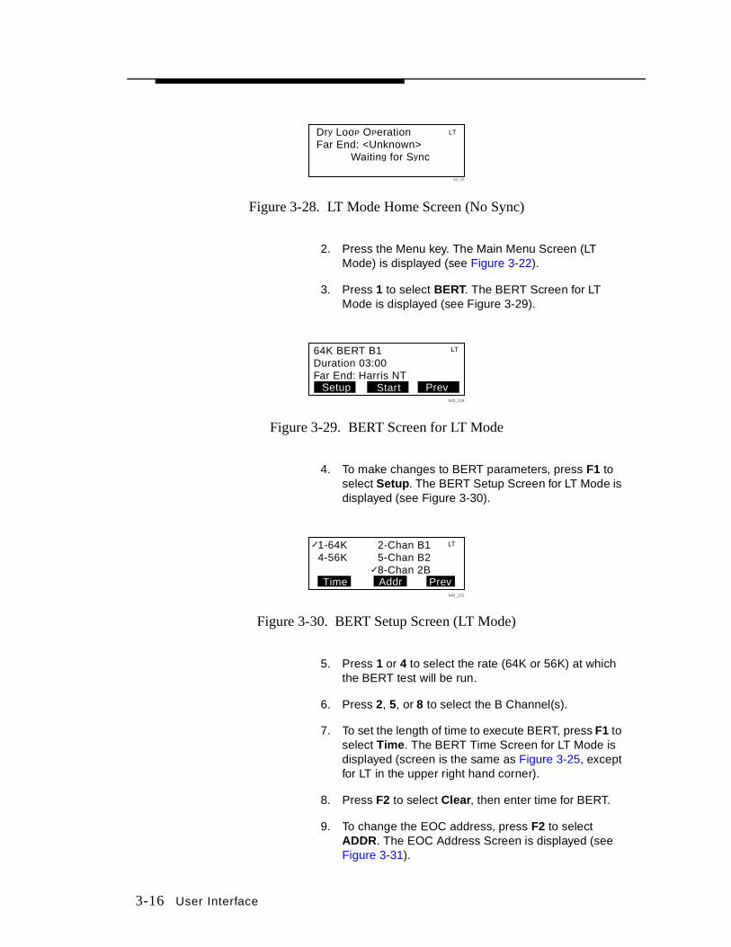
Figure 3-28. LT Mode Home Screen (No Sync)
2. Press the Menu key. The Main Menu Screen (LT Mode) is displayed (see Figure 3-22).
3. Press 1 to select BERT. The BERT Screen for LT Mode is displayed (see Figure 3-29).
Figure 3-29. BERT Screen for LT Mode
4. To make changes to BERT parameters, press F1 to select Setup. The BERT Setup Screen for LT Mode is displayed (see Figure 3-30).
Figure 3-30. BERT Setup Screen (LT Mode)
5. Press 1 or 4 to select the rate (64K or 56K) at which the BERT test will be run.
6. Press 2, 5, or 8 to select the B Channel(s).
7. To set the length of time to execute BERT, press F1 to select Time. The BERT Time Screen for LT Mode is displayed (screen is the same as Figure 3-25, except for LT in the upper right hand corner).
8. Press F2 to select Clear, then enter time for BERT.
9. To change the EOC address, press F2 to select ADDR. The EOC Address Screen is displayed (see Figure 3-31).
Dry LooP OPerationFar End: <Unknown>
Waiting for Sync
LT
bit2_129
64K BERT B1Duration 03:00Far End: Harris NT
LT
Start PrevSetupbit2_119
1-64K4-56K
Time
LT2-Chan B15-Chan B28-Chan 2B
Prevbit2_121
Addr

User Interface 3-17
Figure 3-31. EOC Address Screen
10. Press F2 to select <BkSp to delete EOC address shown on display. The cursor moves backward to delete the existing EOC. Press and hold <BkSp to delete multiple digits.
Note: The EOC address is not saved when you power down.
11. Use the keypad to enter to enter the new EOC address of the device you want to BERT. Only addresses 0 through 7 are valid.
12. Press F3 to select Save and return to the previous screen.
For Dry Loop Operations (LT Mode or NT1+TE Synced to a Harris LT) (see Figure 3-27), BERT parameters may be set as follows:
1. Verify the units are in Dry Loop Operations and sync has been established (see Figure 3-32).
Figure 3-32. LT Mode Home Screen (in Sync)
2. Press F1 on either unit to select BERT. The BERT Screen for LT Mode is displayed (see Figure 3-29).
3. To make changes to BERT parameters, press F1 to select Setup. The BERT Setup Screen for LT Mode is displayed (see Figure 3-30).
4. Press 1 or 4 to select the rate (64K or 56K) at which BERT will be run.
5. Press 2, 5, or 8 to select the B Channel loopbacks.
EOC Address:0_
0(NT)-7 are validDetect <Bksp Save
bit2_216
LT
Dry Loop OperationFar End: Harris NT Far End Ready
Auto
LT
BERT Hookbit2_118
Dry LooP OPerationFar End: Harris LT Far End Ready
NT
AutoBERT Hookbit2_204
Test Set 2Test Set 1
3-18 User Interface
6. To set the length of time to execute BERT, press F1 to select Time. The BERT Time Screen for LT Mode is displayed (screen is the same as Figure 3-25, except for LT in the upper right hand corner).
7. Press F2 to select Clear, then enter time for BERT.
8. Press F3 to select Save and return to the previous screen.
Making a Single BERT Test in NT1+TE or TE Mode
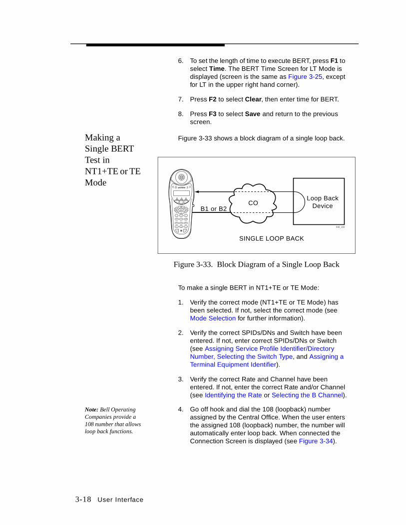
Figure 3-33 shows a block diagram of a single loop back.
Figure 3-33. Block Diagram of a Single Loop Back
To make a single BERT in NT1+TE or TE Mode:
1. Verify the correct mode (NT1+TE or TE Mode) has been selected. If not, select the correct mode (see Mode Selection for further information).
2. Verify the correct SPIDs/DNs and Switch have been entered. If not, enter correct SPIDs/DNs or Switch (see Assigning Service Profile Identifier/Directory Number, Selecting the Switch Type, and Assigning a Terminal Equipment Identifier).
3. Verify the correct Rate and Channel have been entered. If not, enter the correct Rate and/or Channel (see Identifying the Rate or Selecting the B Channel).
Note: Bell Operating Companies provide a 108 number that allows loop back functions.
4. Go off hook and dial the 108 (loopback) number assigned by the Central Office. When the user enters the assigned 108 (loopback) number, the number will automatically enter loop back. When connected the Connection Screen is displayed (see Figure 3-34).
Loop BackDeviceCO
SINGLE LOOP BACK
B1 or B2
Sync OffHook Volt
Chg
bit2_102
User Interface 3-19
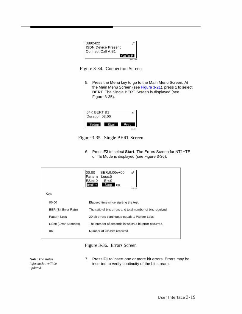
Figure 3-34. Connection Screen
5. Press the Menu key to go to the Main Menu Screen. At the Main Menu Screen (see Figure 3-21), press 1 to select BERT. The Single BERT Screen is displayed (see Figure 3-35).
Figure 3-35. Single BERT Screen
6. Press F2 to select Start . The Errors Screen for NT1+TE or TE Mode is displayed (see Figure 3-36).
Figure 3-36. Errors Screen
Note: The status information will be updated.
7. Press F1 to insert one or more bit errors. Errors may be inserted to verify continuity of the bit stream.
3892422ISDN Device PresentConnect Call A:B1
GoTo B
NT
bit2_099
64K BERT B1Duration 03:00
NT
Start PrevSetupbit2_041
00:00 BER:0.00e+00Pattern Loss:0ESec:0 Err:0
StopInsErr 0K
NT
bit2_042
Key:
00:00 Elapsed time since starting the test.
BER (Bit Error Rate) The ratio of bits errors and total number of bits received.
Pattern Loss 20 bit errors continuous equals 1 Pattern Loss.
ESec (Error Seconds) The number of seconds in which a bit error occurred.
0K Number of kilo bits received.

3-20 User Interface
8. Press F2 to select Stop. The Stop Screen for NT1+TE or TE Mode is displayed (see Figure 3-37). If stop is not selected, the BERT will automatically stop after the BERT duration.
Figure 3-37. Stop Screen
9. To end the call, press the On/Off H ook key.
10. Press F3 to select Clear and return to the Home Screen (see Figure 3-3).
Making a BERT in LT Mode
There are three ways to run BERT in LT mode: through the BERT function key, through the Auto function key, or through the Main Menu.
1. Verify the correct mode (LT Mode) has been selected. If not, select the correct mode (see Mode Selection for further information).
2. Wait for Sync (green light is displayed under Sync on LCD).
3. At the LT Mode Home Screen (in Sync) (see Figure 3-32) select one of the following options:
a. Press F1 to select BERT or press the Menu Key then press 1 to select BERT. The BERT Screen for LT Mode (see Figure 3-29) is displayed on the LT test set. The display on the NT1+TE test set does not change (see Figure 3-32).
b. Press F3 to select AUTO or press the Menu Key then press 4 to select AUTO.
Note: BERT test may be started from either test set.
4. Press F2 to select Start . The Errors Screen is displayed on the LT test set (see Figure 3-36). The Loopback Screen (see Figure 3-38) is displayed on the NT1+TE test set.
01:25 BER:0.00e+00Pattern Loss:0ESec:0 Err:0Setup PrevStart
bit2_085
NT

User Interface 3-21
Figure 3-38. Loopback Screen
Note: The status information will be updated.
5. Press F1 to insert one or more bit errors. Errors may be inserted to verify continuity of the Bit stream.
6. Press F2 to select Stop. The BERT Screen for LT mode is displayed (see Figure 3-29) on the LT test set. The Return to Normal Screen is displayed on the NT1+TE test set (see Figure 3-39). If stop is not selected, the test will continue for the BERT function (see Setting BERT Parameters).
Figure 3-39. Return To Normal Screen
7. Press F3 to select PREV and return to the previous screen or the Menu Key to return to the LT Mode Home Screen.
Dual BERT Call Yourself
The Auto function key on the Main Menu allows the test set to call from one B channel to the other channel, then answer the incoming call and initiate a 2B BERT. Figure 3-40 shows a block diagram of a dual BERT.
Figure 3-40. Block Diagram of a Dual BERT
Last: B2 LooPbackLooPbacks: 2BCorruPted CRCs: None
NT
Prevbit2_131
Last: Return to NormLooPbacks: NoneCorruPted CRCs: None
Prev
NT
bit2_132
Loop Back
Perform Test
CO
Call B
Call A
2B Loop BackTest Set
bit2_101
3-22 User Interface
There are two ways to perform a BERT auto call yourself in NT1+TE or TE Mode: through the Auto option or through the BERT option on the Main Menu.
Method 1: through the Auto Option (see Figure 3-21):
1. Verify the correct mode (NT1+TE, TE, or LT Mode) has been selected. If not, select the correct mode (see Mode Selection for further information).
2. Verify the correct SPIDs/DNs have been entered. If not, enter correct SPIDS and/or DNs (see Assigning Service Profile Identifier/Directory Number).
3. Verify the correct Rate, Channel, and TEI have been entered. If not, enter the correct Rate, Channel and/or TEI (see Identifying the Rate, Selecting the B Channel, or Assigning a TEI).
4. At the Main Menu Screen (see Figure 3-21 or Figure 3-22), press 4 to select Auto. The number is dialed and the Connection Screen is displayed (see Figure 3-34).
5. The unit will automatically start to perform a 128K (or 112K for 56K BERT rate) BERT and enter the Errors Screen (see Figure 3-36).
Note: The status information will be updated.
6. Press F1 to insert one or more BERT errors. Errors may be inserted to verify continuity of the bit stream.
7. Press F2 to select Stop. The Stop Screen is displayed (see Figure 3-37). If stop is not selected, the BERT will automatically stop after running for the BERT duration.
8. To end the call, press the On/Off H ook key.
9. Press F3 to select Clear and return to the Home Screen (see Figure 3-3).
Method 2: through the BERT option (see Figure 3-21).
1. Verify the correct mode (NT1+TE or TE) has been selected. If not, select the correct mode (see Mode Selection for further information).
2. Verify the correct SPIDs/DNs have been entered. If not, enter correct SPIDS and/or DNs (see Assigning Service Profile Identifier/Directory Number).
3. Verify the correct Rate, Channel, and TEI have been entered. If not, enter the correct Rate, Channel and/or TEI (see Identifying the Rate, Selecting the B Channel, or Assigning a TEI).
User Interface 3-23
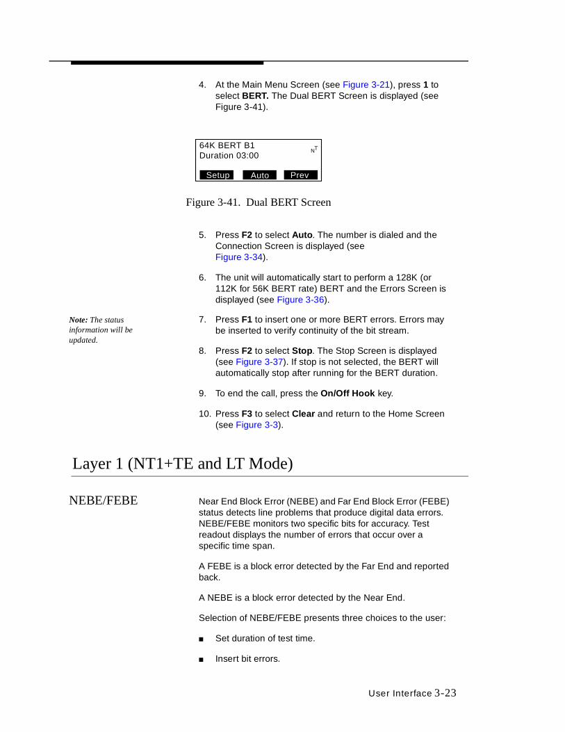
4. At the Main Menu Screen (see Figure 3-21), press 1 to select BERT. The Dual BERT Screen is displayed (see Figure 3-41).
Figure 3-41. Dual BERT Screen
5. Press F2 to select Auto. The number is dialed and the Connection Screen is displayed (seeFigure 3-34).
6. The unit will automatically start to perform a 128K (or 112K for 56K BERT rate) BERT and the Errors Screen is displayed (see Figure 3-36).
Note: The status information will be updated.
7. Press F1 to insert one or more BERT errors. Errors may be inserted to verify continuity of the bit stream.
8. Press F2 to select Stop. The Stop Screen is displayed (see Figure 3-37). If stop is not selected, the BERT will automatically stop after running for the BERT duration.
9. To end the call, press the On/Off Hook key.
10. Press F3 to select Clear and return to the Home Screen (see Figure 3-3).
Layer 1 (NT1+TE and LT Mode)
NEBE/FEBE Near End Block Error (NEBE) and Far End Block Error (FEBE) status detects line problems that produce digital data errors. NEBE/FEBE monitors two specific bits for accuracy. Test readout displays the number of errors that occur over a specific time span.
A FEBE is a block error detected by the Far End and reported back.
A NEBE is a block error detected by the Near End.
Selection of NEBE/FEBE presents three choices to the user:
■ Set duration of test time.
■ Insert bit errors.
64K BERT B1Duration 03:00
NT
Auto PrevSetup
3-24 User Interface
■ Clear sets NEBE/FEBE errors and Esec to zero, and the timer to zero.
To access NEBE/FEBE:
1. Verify the correct mode (NT1+TE or LT Mode) has been selected. If not, select the correct mode (see Mode Selection for further information).
2. Wait for Sync (green or amber light is displayed under Sync above LCD), then press the Menu key.
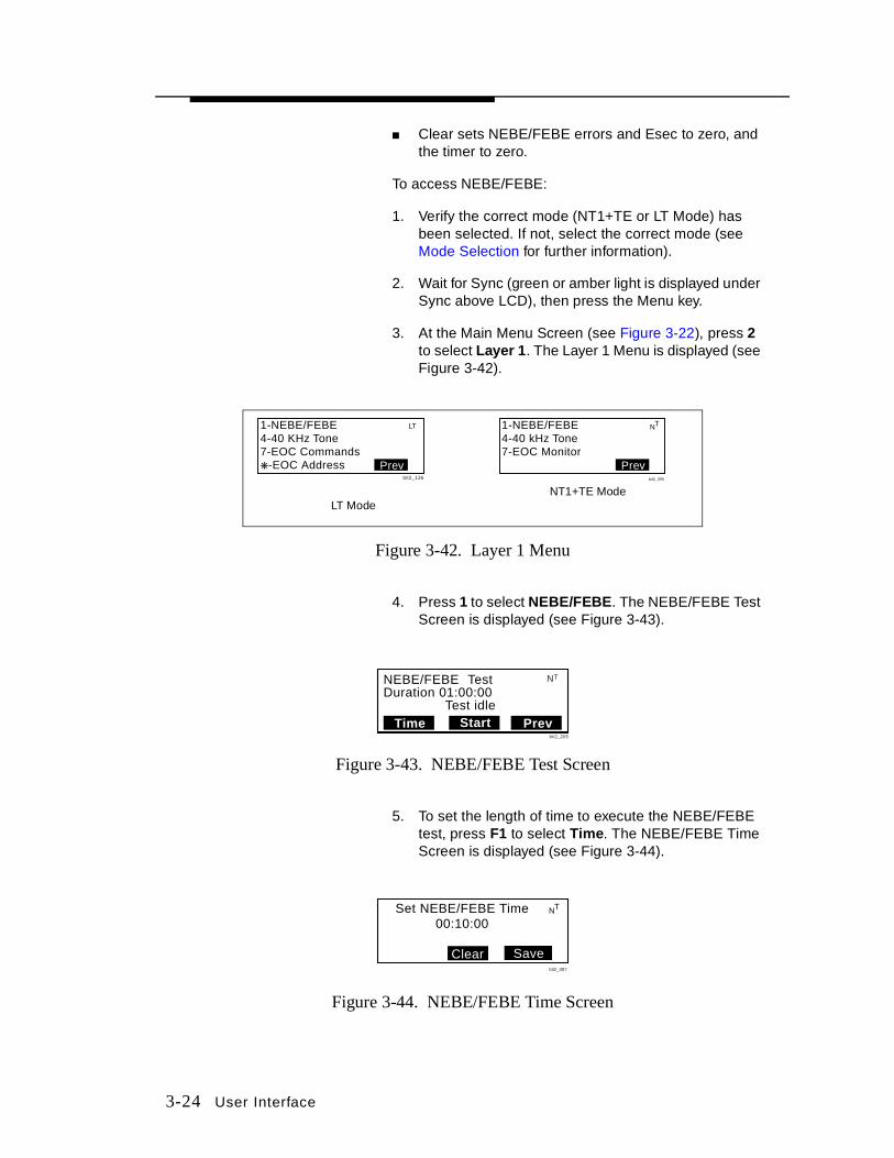
3. At the Main Menu Screen (see Figure 3-22), press 2 to select Layer 1. The Layer 1 Menu is displayed (see Figure 3-42).
Figure 3-42. Layer 1 Menu
4. Press 1 to select NEBE/FEBE. The NEBE/FEBE Test Screen is displayed (see Figure 3-43).
Figure 3-43. NEBE/FEBE Test Screen
5. To set the length of time to execute the NEBE/FEBE test, press F1 to select Time. The NEBE/FEBE Time Screen is displayed (see Figure 3-44).
Figure 3-44. NEBE/FEBE Time Screen
1-NEBE/FEBE4-40 kHz Tone7-EOC Monitor
Prev
NT
bit2_095
1-NEBE/FEBE4-40 KHz Tone7-EOC Commandsk-EOC Address Prev
LT
bit2_136
LT ModeNT1+TE Mode
NEBE/FEBE TestDuration 01:00:00
Test idleTime Start Prev
NT
bit2_205
Set NEBE/FEBE Time00:10:00
SaveClear
NT
bit2_087
User Interface 3-25
6. Press F2 to select Clear, then enter the time for the NEBE/FEBE test.
7. Press F3 to select Save and return to the previous screen.
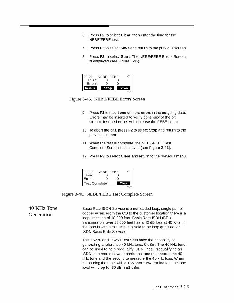
8. Press F2 to select Start . The NEBE/FEBE Errors Screen is displayed (see Figure 3-45).
Figure 3-45. NEBE/FEBE Errors Screen
9. Press F1 to insert one or more errors in the outgoing data. Errors may be inserted to verify continuity of the bit stream. Inserted errors will increase the FEBE count.
10. To abort the call, press F2 to select Stop and return to the previous screen.
11. When the test is complete, the NEBE/FEBE Test Complete Screen is displayed (see Figure 3-46).
12. Press F3 to select Clear and return to the previous menu.
Figure 3-46. NEBE/FEBE Test Complete Screen
40 KHz Tone Generation
Basic Rate ISDN Service is a nonloaded loop, single pair of copper wires. From the CO to the customer location there is a loop limitation of 18,000 feet. Basic Rate ISDN (BRI) transmission, over 18,000 feet has a 42 dB loss at 40 KHz. If the loop is within this limit, it is said to be loop qualified for ISDN Basic Rate Service.
The TS220 and TS250 Test Sets have the capability of generating a reference 40 kHz tone, 0 dBm. The 40 kHz tone can be used to help prequalify ISDN lines. Prequalifying an ISDN loop requires two technicians: one to generate the 40 kHz tone and the second to measure the 40 kHz loss. When measuring the tone, with a 135 ohm ±1% termination, the tone level will drop to -60 dBm ±1 dBm.
00:00 NEBE FEBE ESec: 0 0 Errors: 0 0InsErr Stop Prev
NT
bit2_044
00:10 NEBE FEBE Esec: 0 0Errors: 0 0
Clear
NT
bit2_206
Test Complete

3-26 User Interface
To access the 40 KHz tone:
1. Verify the correct modes (NT1+TE or LT Mode) have been selected. If not, select the correct mode (see Mode Selection for further information).
2. At the Main Menu Screen (see Figure 3-21 or Figure 3-22), press 2 to select Layer 1. The Layer 1 Menu is displayed (see Figure 3-42).
3. At the Layer 1 Menu (LT Mode), press 4 to select 40 kHz Tone. If the test set had Sync, an Action Screen is displayed (see Figure 3-47).
Figure 3-47. Action Screen
4. Press F1 to select YES. The 40 kHz Screen is displayed (see Figure 3-48). Pressing F2 to select NO will return you to the Layer 1 Menu (LT Mode) (see Figure 3-42).
Figure 3-48. 40 KHz Screen
5. Press F3 to select Stop.
6. Press F3 to select Previous and return to the previous menu.
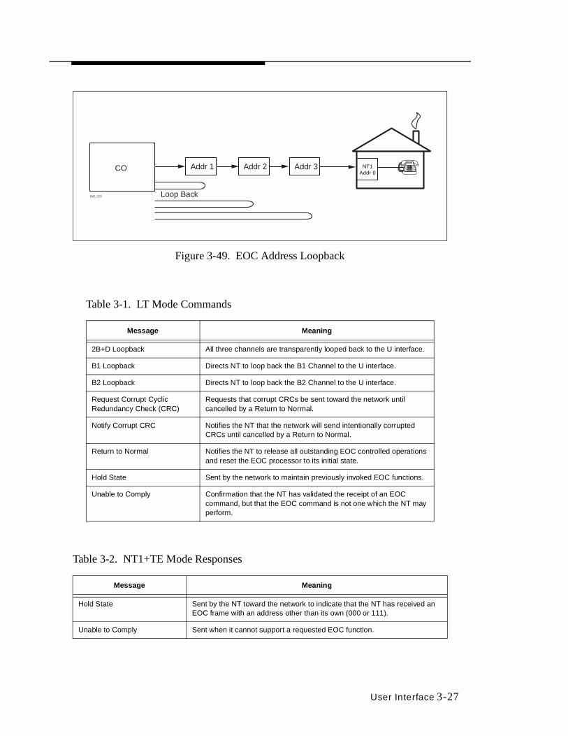
Embedded Operations Channel
The Embedded Operations Channel (EOC) is a communications channel between the NT1 and the CO (see Figure 3-49). Embedded in the maintenance channel on the U Interface, it is used for maintenance information and testing. The LT Mode commands are listed in Table 3-1. When in LT Mode, the commands are issued. When in NT1+TE Mode, the test set acts as a monitor and commands are responded to (see Table 3-2).
This function willcause loss of SyncOK to continue?
Yes No
LT
bit2_139
40 kHz tone active
Stop
LT
bit2_109
User Interface 3-27
Figure 3-49. EOC Address Loopback
Table 3-1. LT Mode Commands
Message Meaning
2B+D Loopback All three channels are transparently looped back to the U interface.
B1 Loopback Directs NT to loop back the B1 Channel to the U interface.
B2 Loopback Directs NT to loop back the B2 Channel to the U interface.
Request Corrupt Cyclic Redundancy Check (CRC)
Requests that corrupt CRCs be sent toward the network until cancelled by a Return to Normal.
Notify Corrupt CRC Notifies the NT that the network will send intentionally corrupted CRCs until cancelled by a Return to Normal.
Return to Normal Notifies the NT to release all outstanding EOC controlled operations and reset the EOC processor to its initial state.
Hold State Sent by the network to maintain previously invoked EOC functions.
Unable to Comply Confirmation that the NT has validated the receipt of an EOC command, but that the EOC command is not one which the NT may perform.
Table 3-2. NT1+TE Mode Responses
Message Meaning
Hold State Sent by the NT toward the network to indicate that the NT has received an EOC frame with an address other than its own (000 or 111).
Unable to Comply Sent when it cannot support a requested EOC function.
CO Addr 1 Addr 2 Addr 3
Loop BackBit2_223
NT1Addr 0
3-28 User Interface
To send EOC commands:
1. Verify the LT mode has been selected. If not, select the correct mode (see Mode Selection for further information).
2. Wait for Sync (green or solid amber light is displayed under Sync above LCD), then press the Menu key.
3. At the Main Menu Screen (LT Mode) (see Figure 3-22), press 2 to select Layer 1. The Layer 1 Menu (LT Mode) is displayed (see Figure 3-42).
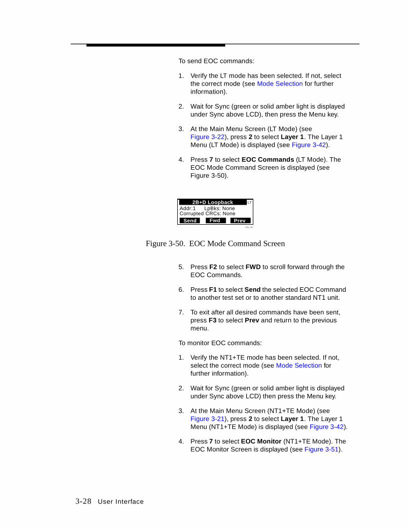
4. Press 7 to select EOC Comman ds (LT Mode). The EOC Mode Command Screen is displayed (see Figure 3-50).
Figure 3-50. EOC Mode Command Screen
5. Press F2 to select FWD to scroll forward through the EOC Commands.
6. Press F1 to select Send the selected EOC Command to another test set or to another standard NT1 unit.
7. To exit after all desired commands have been sent, press F3 to select Prev and return to the previous menu.
To monitor EOC commands:
1. Verify the NT1+TE mode has been selected. If not, select the correct mode (see Mode Selection for further information).
2. Wait for Sync (green or solid amber light is displayed under Sync above LCD) then press the Menu key.
3. At the Main Menu Screen (NT1+TE Mode) (see Figure 3-21), press 2 to select Layer 1. The Layer 1 Menu (NT1+TE Mode) is displayed (see Figure 3-42).
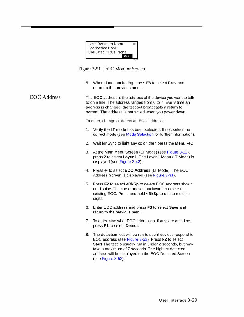
4. Press 7 to select EOC Monitor (NT1+TE Mode). The EOC Monitor Screen is displayed (see Figure 3-51).
Addr:1 LpBks: NoneCorrupted CRCs: None
Send Fwd Prev
2B+D Loopba ck LT
bit2_122
User Interface 3-29
Figure 3-51. EOC Monitor Screen
5. When done monitoring, press F3 to select Prev and return to the previous menu.
EOC Address The EOC address is the address of the device you want to talk to on a line. The address ranges from 0 to 7. Every time an address is changed, the test set broadcasts a return to normal. The address is not saved when you power down.
To enter, change or detect an EOC address:
1. Verify the LT mode has been selected. If not, select the correct mode (see Mode Selection for further information).
2. Wait for Sync to light any color, then press the Menu key.
3. At the Main Menu Screen (LT Mode) (see Figure 3-22), press 2 to select Layer 1. The Layer 1 Menu (LT Mode) is displayed (see Figure 3-42).
4. Press ❋ to select EOC Add ress (LT Mode). The EOC Address Screen is displayed (see Figure 3-31).
5. Press F2 to select <BkSp to delete EOC address shown on display. The cursor moves backward to delete the existing EOC. Press and hold <BkSp to delete multiple digits.
6. Enter EOC address and press F3 to select Save and return to the previous menu.
7. To determine what EOC addresses, if any, are on a line, press F1 to select Detect.
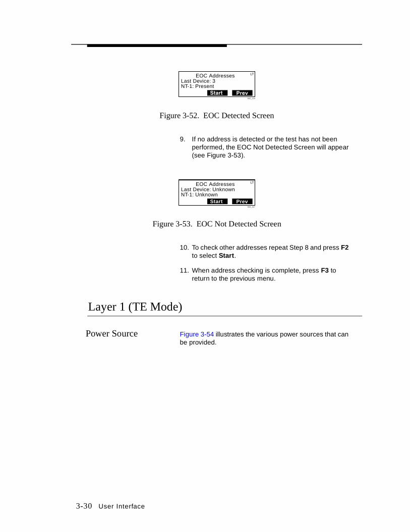
8. The detection test will be run to see if devices respond to EOC address (see Figure 3-52). Press F2 to select Start .The test is usually run in under 2 seconds, but may take a maximum of 7 seconds. The highest detected address will be displayed on the EOC Detected Screen (see Figure 3-52).
Last: Return to NormLooPbacks: NoneCorruPted CRCs: None
Prev
NT
bit2_132
3-30 User Interface
Figure 3-52. EOC Detected Screen
9. If no address is detected or the test has not been performed, the EOC Not Detected Screen will appear (see Figure 3-53).
Figure 3-53. EOC Not Detected Screen
10. To check other addresses repeat Step 8 and press F2 to select Start .
11. When address checking is complete, press F3 to return to the previous menu.
Layer 1 (TE Mode)
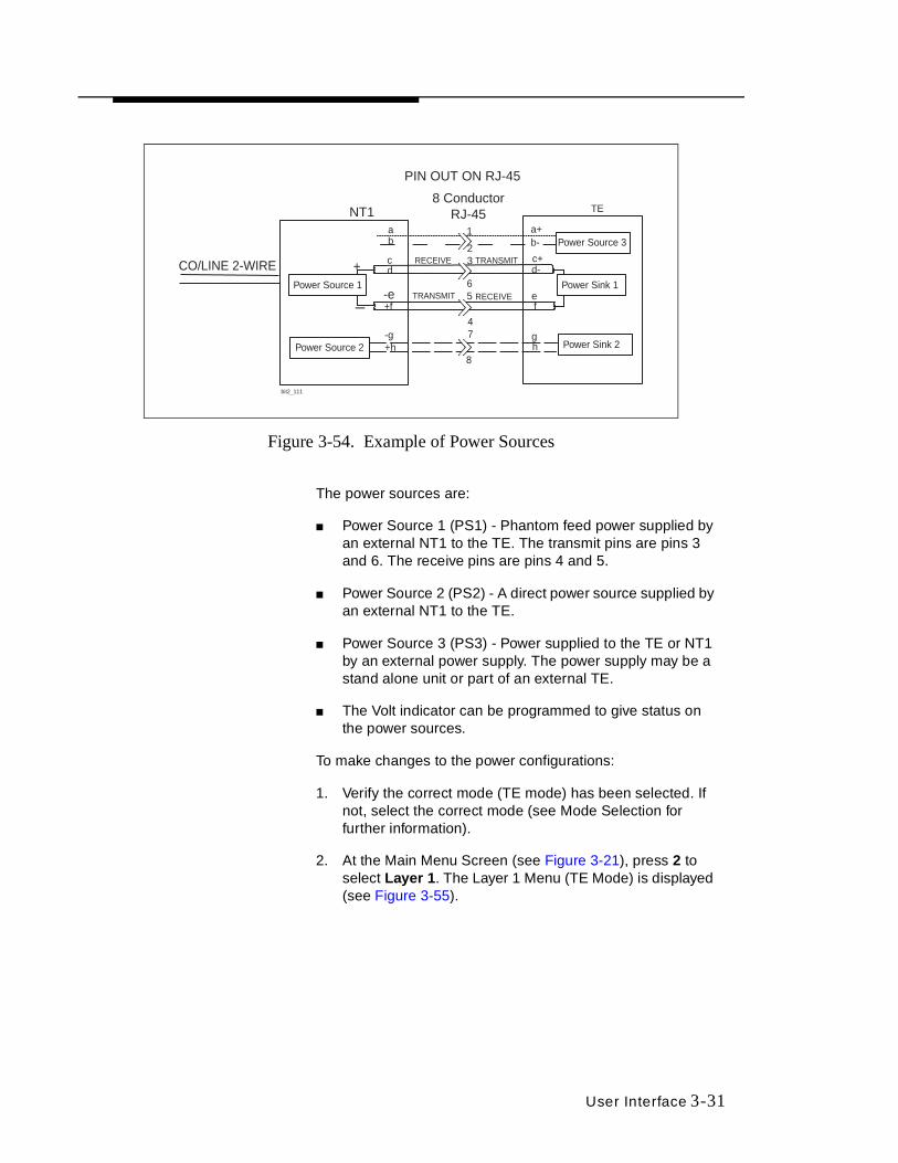
Power Source Figure 3-54 illustrates the various power sources that can be provided.
Last Device: 3NT-1: Present
Start Prevbit2_224
LTEOC Addresses
Last Device: UnknownNT-1: Unknown
Star t Prevbit2_217
LTEOC Addresses
User Interface 3-31
Figure 3-54. Example of Power Sources
The power sources are:
■ Power Source 1 (PS1) - Phantom feed power supplied by an external NT1 to the TE. The transmit pins are pins 3 and 6. The receive pins are pins 4 and 5.
■ Power Source 2 (PS2) - A direct power source supplied by an external NT1 to the TE.
■ Power Source 3 (PS3) - Power supplied to the TE or NT1 by an external power supply. The power supply may be a stand alone unit or part of an external TE.
■ The Volt indicator can be programmed to give status on the power sources.
To make changes to the power configurations:
1. Verify the correct mode (TE mode) has been selected. If not, select the correct mode (see Mode Selection for further information).
2. At the Main Menu Screen (see Figure 3-21), press 2 to select Layer 1 . The Layer 1 Menu (TE Mode) is displayed (see Figure 3-55).
1ab
cd
-
+
NT1
PIN OUT ON RJ-45
8 ConductorRJ-45
23
65
47
8Power Source 2
CO/LINE 2-WIREPower Source 1
Power Source 3
Power Sink 1
Power Sink 2
RECEIVE
TRANSMIT
TRANSMIT
RECEIVE-e+f
-g+h
TE
a+b-
c+d-
ef
gh
bit2_111

3-32 User Interface
Figure 3-55. Layer 1 Menu (TE Mode)
3. Press 1 to select Power Sources . The Power Source Screen is displayed (see Figure 3-56).
Figure 3-56. Power Source Screen
4. Press 1, 4, 7, or press F1 to select ANY.
5. If 1, 4 or 7 is pressed, the word Light , in parentheses, is placed after the PS entry. If Any is selected, the word Light is placed after all of the entries (see Figure 3-56) and one of the following conditions will occur:
Note: The LED will follow the light.
a. If one or more of the PS entries has a positive voltage (positive indicator), the Volt light will turn green (see Figure 3-57).
Figure 3-57. Voltage (Volt) Indicator Screen
b. If one or more of the PS entries does not have voltage (negative indicator), the Volt light will remain red (see Figure 3-57).
c. If there is a combination of positive and negative power sources, the Volt light will remain red.
6. Press F3 to return to the previous screen.
1-Power Sources4-Q Channel7-96 kHz Tone
Prev
TE
bit2_108
1-PS1=None (Light)4-PS2=None (Light)7-PS3=None (Light)
Prev
TE
Anybit2_107
1-PS1=Pos (Light)4-PS2=Neg7-PS3=Neg
Prev
TE
Anybit2_135

User Interface 3-33
Q Channel The S/T Maintenance Channel (Q Channel) is the maintenance signaling channel provided from a TE to an NT1 over the S/T interface (ANSI T1.605-1991). The Q Channel allows signaling control functions over layer 1 (e.g., B1, B2 or 2B loopbacks). The maintenance channel functions are listed in Table 3-3.
To send Q Channel commands:
1. Verify the TE Mode has been selected. If not, select the correct mode (see Mode Selection for further information).
2. At the Main Menu Screen (see Figure 3-21), press 2 to select Layer 1 . The Layer 1 Menu (TE Mode) is displayed (see Figure 3-55).
3. Press 4 to select Q Channel. The Q Channel Screen is displayed (see Figure 3-58).
4. Press F2 to select Fwd and scroll forward through the Q Channel messages (see Table 3-3).
Figure 3-58. Q Channel Screen
5. Press F1 to select Send.
6. To exit after all desired Q channel commands have been sent, press F3 to return to the previous screen.
Table 3-3. Q Channel Messages
Message Meaning
Idle Channel (NORMAL) Default state of the S/T maintenance channel.
Loopback B1 Requests NT1 to loop back Channel B1.
Loopback B2 Requests NT1 to loop back Channel B2.
Loopback 2B Requests NT1 to loop back both channels.
Loss-of-Power Indicator An indicator to the TEs that the NT has lost power.
Request Self Test The TE can request that the NT perform a self test. The scope of the self test is not defined. The self test report returning from the NT1 indicates pass (STP) or fail (STF).
Active LPBks: NoneSC1: Idle Channel
Send Fwd Prev
Idle Channel TE
bit2_120
3-34 User Interface
96 KHz Tone Generation
In this mode of operation, the TS250 Test Set has the capability to generate a 96 kHz tone (1.5 Volts peak to peak nominal, when terminated with 100 ohms) per ANSI T1.605 (1991). The tone can be used as a tracer tone.
To access the 96 kHz tone:
1. Verify the correct mode (TE mode) has been selected. If not, select the correct mode (see Mode Selection for further information).
2. At the Main Menu Screen (see Figure 3-21), press 2 to select Layer 1 . The Layer 1 Menu (TE Mode) is displayed (see Figure 3-55).
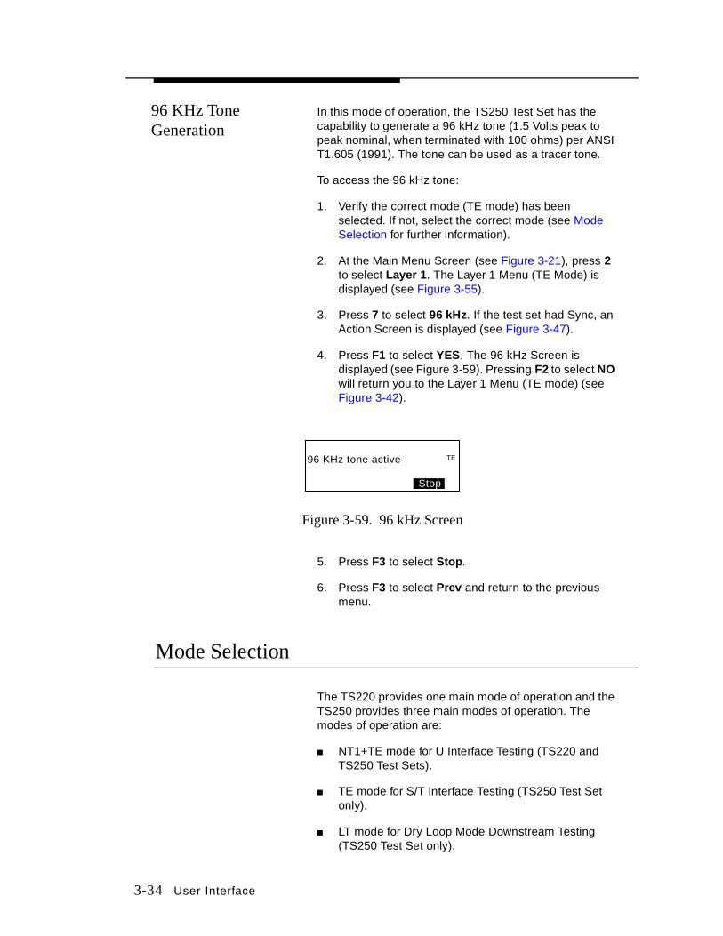
3. Press 7 to select 96 kHz. If the test set had Sync, an Action Screen is displayed (see Figure 3-47).
4. Press F1 to select YES. The 96 kHz Screen is displayed (see Figure 3-59). Pressing F2 to select NO will return you to the Layer 1 Menu (TE mode) (see Figure 3-42).
Figure 3-59. 96 kHz Screen
5. Press F3 to select Stop.
6. Press F3 to select Prev and return to the previous menu.
Mode Selection
The TS220 provides one main mode of operation and the TS250 provides three main modes of operation. The modes of operation are:
■ NT1+TE mode for U Interface Testing (TS220 and TS250 Test Sets).
■ TE mode for S/T Interface Testing (TS250 Test Set only).
■ LT mode for Dry Loop Mode Downstream Testing (TS250 Test Set only).
96 KHz tone active
Stop
TE

User Interface 3-35
NT1+TE Mode
NT1+TE mode (see Figure 3-60) allows the user to:
■ Make voice and data calls.
■ Perform BERT tests.
Figure 3-60. NT1+TE Mode (TS220 and TS250)
■ Make X.25 D Packet calls.
■ Monitor the maintenance channel.
■ Display various data information.
Line Termination (LT) Mode
Line Termination (LT) mode (see Figure 3-61) allows the user to look like the line card inside the CO. In this mode the user can perform (physical layer) testing down stream.
TE Mode
Notes: 1. TE Mode is not available on the TS220 Model.
2. Only one device should be terminated on passive bus configuration and it should be the furthest device from the NT1.
TE Mode can be either terminated or unterminated. In terminated mode, the receiver and the transmitter are terminated with 100 ohms. In a unterminated phase, there is not 100 ohms across the receiver and the transmitter. Figure 3-62 shows where the S/T is terminated, behind the NT1. TE mode allows the user to:
■ Display various data information.
■ Perform BERT test.
■ Make a voice or data call.
■ Make X.25 D Packet calls.
■ Send command via Q Channel.
Sync OffHook Volt
Chg
COU Interfacebit2_106

3-36 User Interface
Note: LT Mode is not available on the TS220 Model.
Figure 3-61. LT Mode
Figure 3-62. TE Mode
Sync OffHook Volt
Chg
Loop BackBERT
NT1S/T
LT MODE - TS250 only
bit2_103
Sync OffHook Volt
Chg Sync OffHook Volt
Chg
U Interface
VoiceBERT
Loop Back
LT MODEbit2_105
Sync OffHook Volt
Chg
NT1S/T
CO
bit2_104

User Interface 3-37
Figure 3-63 illustrates the standard line cord and the various line cord accessories, and the physical connections.
Figure 3-63. Line Cord and Accessories
Setting/Changing Modes
To set or change modes (TS250 only):
1. At the Main Menu screen (see Figure 3-21 or Figure 3-22), press ❋ to select Mode. The Mode Setup screen is displayed (see Figure 3-64).
Figure 3-64. Mode Setup Screen
2. Press one of the following numbers:
a. 1 to select NT1+TE.
b. 4 to select TE Terminated.
c. 7 to select TE Unterminated.
d. ❋ to select LT.
10220-100
6 CONDUCTOR
WA
LL
Banjo
RJ-45
RED
BLACK
REC+PIN 5
REC -PIN 4
TRAN -PIN 6
RED
BLACK
TRAN +PIN 3
RJ-11C RJ-11C
banjo - 8
TS220/TS250 Cable"strain relief"
bit2_110
1-NT1+TE Mode4-TE Terminated7-TE Unterminated -LT Mode Prev
NT
* bit2_045
3-38 User Interface
Centrex
Centrex is a business telephone service or a Private Branch Exchange (PBX), offered by local telephone companies from local central offices. It is similar to the individual lines delivered to individual desks with special features on the lines (e.g., intercom, call forwarding, call transfer, etc.). When dialing from a centrex setup, it is often necessary to dial 9 (or another prefix) to get an outside line.
If enabled, the Centrex function can insert a prefix of up to 10 digits. The user may edit the number to dial out. The prefix insertion is only active when activating memory dial or call yourself BERT and the Centrex function is on. For example:
■ Set the prefix to 9.
■ Store the number 527-8729 in location 1.
■ Recall location 1 and select dial.
■ The number dialed out is 9-527-8729.
To access the Centrex function:
1. Verify the correct mode (NT1+TE or TE Mode) has been selected. If not, select the correct mode (see Mode Selection for further information).
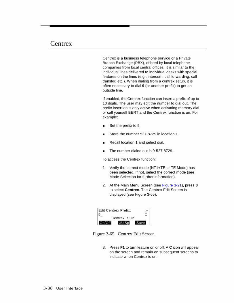
2. At the Main Menu Screen (see Figure 3-21), press 8 to select Centrex . The Centrex Edit Screen is displayed (see Figure 3-65).
Figure 3-65. Centrex Edit Screen
3. Press F1 to turn feature on or off. A C icon will appear on the screen and remain on subsequent screens to indicate when Centrex is on.
Edit Centrex Prefix:9_
Save
NT
On/Off BkSpCentrex is On
C

User Interface 3-39
4. Press F2 to select <BkSp to delete the number shown on the display. The cursor moves backward to delete the existing number.
5. Press F3 to select Save and return to Main Menu Screen.
View
The View function key stores information on the last call attempt that took place on Call A, Call B, and/or Call D and Cause Messages (see Cause Messages Section for more information) about what happened in that attempt. View also provides the results of previous BERTs, previous data from self tests, and the current version of software being used in the test set.
NT1+TE or TE Mode
To access the View key in NT1+TE or TE Mode:
1. Verify the correct mode (NT1+TE or TE Mode) has been selected. If not, select the correct mode (see Mode Selection for further information).
2. At the Main Menu Screen (NT1+TE or TE Mode) (see Figure 3-21), press 7 to select View. The View Screen (NT1+TE or TE Mode) is displayed (see Figure 3-66).
Figure 3-66. View Screen
3. Select one of the following options (see Figure 3-66):
a. Press 1 to view BERT results.
b. Press 2 to see what version of software is currently being used.
c. Press 4 to view results of Call A attempts.
d. Press 5 to view self test results.
e. Press 7 to view results of Call B attempts.
1-BERT4-Call A7-Call B -Call D Prev
TE2-Version5-Selftest
bit2_112*
1-BERT4-Call A7-Call B -Call D
2-Version5-Selftest8-BlkErr
Prev
NT
*bit2_182
NT1+TE Mode TE Mode

3-40 User Interface
f. Press 8 to view NEBE/FEBE (NT1+TE) test results.
g. Press ❋ to view results of Call D attempts.
LT Mode To access the View key in LT Mode:
1. Verify the correct mode (LT Mode) has been selected. If not, select the correct mode (see Mode Selection for further information).
2. At the Main Menu Screen (LT Mode) (see Figure 3-22), press 7 to select View. The View Screen (LT Mode) is displayed (see Figure 3-67).
Figure 3-67. View Screen (LT Mode)
3. Select one of the following options:
a. Press 1 to view BERT results.
b. Press 2 to see what version of software is currently being used.
c. Press 4 to view results of call attempts.
d. Press 5 to view self test results.
e. Press 8 to view results of NEBE/FEBE tests.
Options for Feature Adjustments
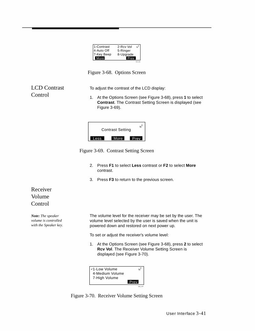
All adjustments to contrast control, receiver volume level, or ringer volume (for all modes) can be made from an Options Screen (see Figure 3-68) which is accessed by pressing 5 to select Opt ions from the Main Menu Screen (see Figure 3-21 or Figure 3-22).
1-BERT 2-Version4-Call 5-Selftest
8-BlkErrPrev
LT
bit2_081
User Interface 3-41
Figure 3-68. Options Screen
LCD Contrast Control
To adjust the contrast of the LCD display:
1. At the Options Screen (see Figure 3-68), press 1 to select Contrast . The Contrast Setting Screen is displayed (see Figure 3-69).
Figure 3-69. Contrast Setting Screen
2. Press F1 to select Less contrast or F2 to select More contrast.
3. Press F3 to return to the previous screen.
Receiver Volume Control
Note: The speaker volume is controlled with the Speaker key.
The volume level for the receiver may be set by the user. The volume level selected by the user is saved when the unit is powered down and restored on next power up.
To set or adjust the receiver’s volume level:
1. At the Options Screen (see Figure 3-68), press 2 to select Rcv Vol . The Receiver Volume Setting Screen is displayed (see Figure 3-70).
Figure 3-70. Receiver Volume Setting Screen
1-Contrast4-Auto Off7-Key Beep
2-Rcv Vol5-Ringer8-Upgrade
Prev
NT
bit2_046
More
Contrast Setting
Less More Prev
NT
1-Low Volume4-Medium Volume7-High Volume
Prevbit2_047
NT

3-42 User Interface
2. Press 1, 4, or 7 to adjust the volume.
3. Press F3 to return to the previous screen.
Auto Off The Auto Off is a feature that allows the user to save battery power when the user has inadvertently left the unit on (adapter is not plugged in or there is no keys pressed and Sync light is not on). It takes 5 minutes of inactivity before a test set will automatically power down. Prior to powering down the unit, a 5 minute warning tone will be heard followed by a message that appears on the screen (see Figure 3-71) before power down begins. After the warning tone is sounded and the message appears, the user has 10 seconds to press any key before the unit powers down.
Figure 3-71. Power Down Warning Screen
1. At the Options Screen (see Figure 3-68), press 4 to select Auto Off. The Auto Setup Screen is displayed (see Figure 3-72).
Figure 3-72. Automatic Setup Screen
2. Press 1 to select Enable and activate the warning feature.
3. Press 4 to select Disable a nd override the automatic power down feature when there is no key activity.
4. Press F3 to return to the previous screen.
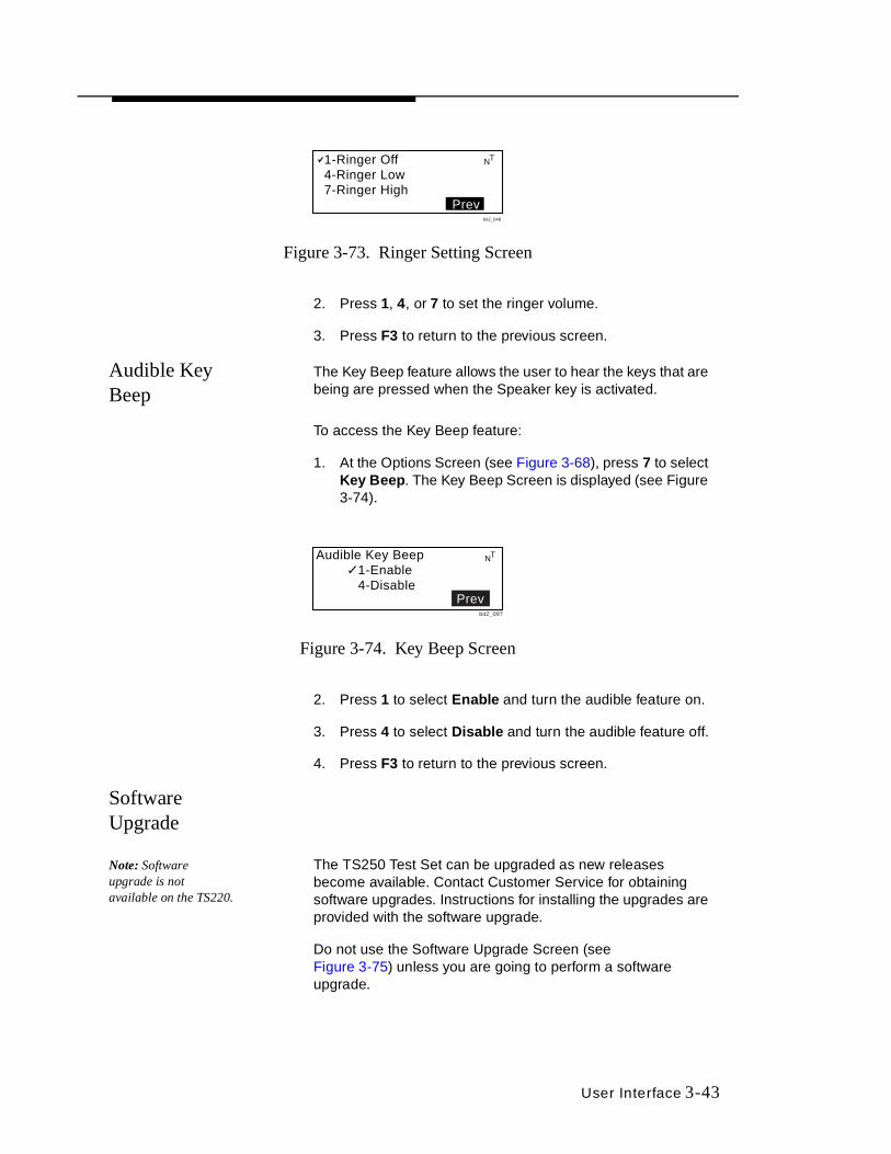
Ringer Volume To set the ringer volume:
1. At the Options Screen (see Figure 3-68), press 5 to select Ringer. The Ringer Setting Screen is displayed (see Figure 3-73).
AUTOMATIC POWER DOWN
Press any key to abort
NT
bit2_098
Automatic Power Down 1-Enable 4-Disable
Prev
NT
bit2_096
User Interface 3-43
Figure 3-73. Ringer Setting Screen
2. Press 1, 4, or 7 to set the ringer volume.
3. Press F3 to return to the previous screen.
Audible Key Beep
The Key Beep feature allows the user to hear the keys that are being are pressed when the Speaker key is activated.
To access the Key Beep feature:
1. At the Options Screen (see Figure 3-68), press 7 to select Key Beep. The Key Beep Screen is displayed (see Figure 3-74).
Figure 3-74. Key Beep Screen
2. Press 1 to select Enable and turn the audible feature on.
3. Press 4 to select Disabl e and turn the audible feature off.
4. Press F3 to return to the previous screen.
Software Upgrade
Note: Software upgrade is not available on the TS220.
The TS250 Test Set can be upgraded as new releases become available. Contact Customer Service for obtaining software upgrades. Instructions for installing the upgrades are provided with the software upgrade.
Do not use the Software Upgrade Screen (see Figure 3-75) unless you are going to perform a software upgrade.
1-Ringer Off4-Ringer Low7-Ringer High
Prevbit2_048
NT
Audible Key Beep 1-Enable 4-Disable
NT
bit2_097
Prev
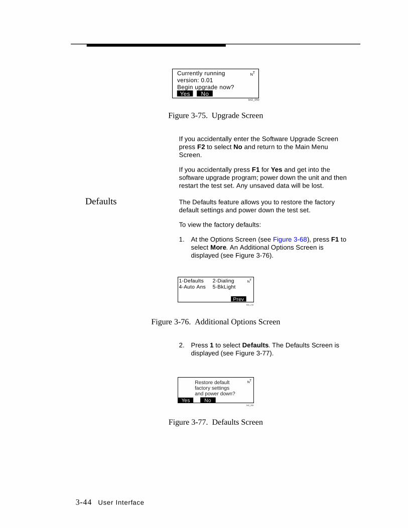
3-44 User Interface
Figure 3-75. Upgrade Screen
If you accidentally enter the Software Upgrade Screen press F2 to select No and return to the Main Menu Screen.
If you accidentally press F1 for Yes and get into the software upgrade program; power down the unit and then restart the test set. Any unsaved data will be lost.
Defaults The Defaults feature allows you to restore the factory default settings and power down the test set.
To view the factory defaults:
1. At the Options Screen (see Figure 3-68), press F1 to select More. An Additional Options Screen is displayed (see Figure 3-76).
Figure 3-76. Additional Options Screen
2. Press 1 to select Default s. The Defaults Screen is displayed (see Figure 3-77).
Figure 3-77. Defaults Screen
Currently runningversion: 0.01Begin upgrade now?Yes No
NT
bit2_050
1-Defaults 2-Dialing4-Auto Ans 5-BkLight
Prev
NT
bit2_210
No
NT
bit2_209
Restore defaultfactory settingsand power down?
Yes

User Interface 3-45
3. Press F1 to select Yes to restore the factory default settings and power the unit down.
4. Press F2 to select No if you do not want to restore the default settings. Pressing No will return you to the previous menu.
Auto Answer and Loopback
To configure the test set to an auto answer and loopback calls:
1. At the Options Screen (see Figure 3-68), press F1 to select More. An Additional Options Screen is displayed (see Figure 3-76).
2. Press 4 to select Auto Ans. The Auto Answer Screen is displayed (see Figure 3-78).
Figure 3-78. Auto Answer Screen
Note: While the test set is in auto answer and loopback mode, the test set may not originate a call.
3. Press 1 to select Enable and activate the auto answer feature. Selecting Enable allows the user to receive calls only, not make outgoing calls.
4. Press 4 to select Disable and override the automatic answer feature.
5. Press F3 to return to the previous screen.
Dialing 1. At the Options Screen (see Figure 3-68), press F1 to select More. An Additional Options Screen is displayed (see Figure 3-76).
2. Press 2 to select Dial ing. The Dialing Options Screen is displayed (see Figure 3-79).
Figure 3-79. Dialing Options Screen
NTAuto Answer1-Enable4-Disable
Prevbit2_212
Local Dialing1-7 Digit4-10 Digit7-11 Digit Prev
bit2_213
NT

3-46 User Interface
3. Selecting one of the following options:
a. Press 1 for 7 digit telephone numbers.
b. Press 4 for 10 digit telephone numbers.
c. Press 7 for 11 digit telephone numbers.
4. Press F3 to return to the previous screen.
Backlight The backlight feature allows the user to set the length of time that the backlight will stay illuminated before it will turn off.
1. At the Options Screen (see Figure 3-68), press F1 to select More. An Additional Options Screen is displayed (see Figure 3-76).
2. Press 5 to select BkLight. The Backlight Screen is displayed (see Figure 3-80).
Figure 3-80. Backlight Screen
Note: The shorter the backlight period, the longer the batteries may last.
3. Select one of the following options:
a. Press 1 for 30 seconds.
b. Press 4 for 5 minutes.
c. Press 7 for none.
4. Press F3 to return to the previous screen.
Recall (Speed Dial) Key
Note: This function not available for Dry Loop Operation.
The Recall key provides access to stored speed dial numbers. To access the Recall functions:
1. When the Home Screen (see Figure 3-3) is displayed, press the Recall key. The Recall Screen is displayed (see Figure 3-81).
NTBacklight Timeout1-30 Seconds4-5 Minutes7-None Prev
bit2_219

User Interface 3-47
Figure 3-81. Recall Screen
Note: Two digits must be entered.
2. To dial a number, press any keys 01 to 20.
3. Press F2 to select FWD to scroll forward. The Location Setup Screen is displayed (see Figure 3-82). Up to 20 locations may be stored in the test set.
4. Press F1 to select Back to scroll backward to location 20. The Location Setup Screen is displayed (see Figure 3-82).
Figure 3-82. Location Setup Screen
5. At the Location Setup Screen, press F2 to select FWD to scroll forward through the locations.
6. Press F1 to select Back to scroll back through the locations.
7. When the desired location is reached, press ❋ to dial the number stored in the location currently displayed.
8. Press the pound (#) key to select Edit . The Recall Edit Screen is displayed (see Figure 3-83).
Figure 3-83. Recall Edit Screen
Enter 01-20 to Dial.Scroll to View/Edit.
Back Fwd Exit
NT
*-Dial #-Edit Location 01
18004372266Back Fwd Exit
NT
Editing Location 01
18004372266_BkSp Save
NT
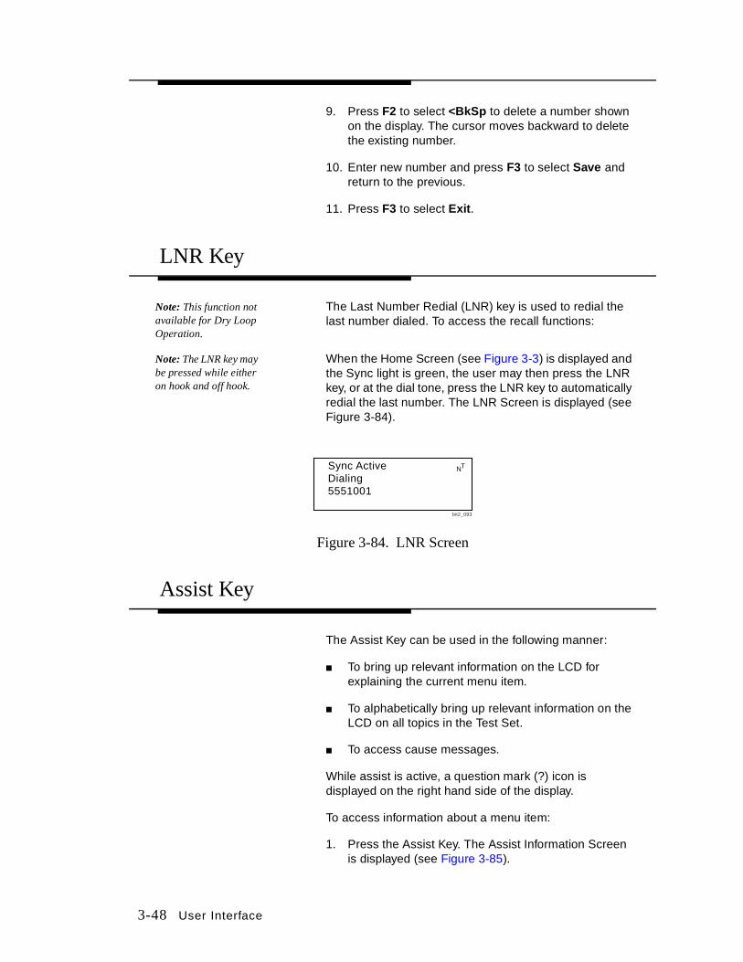
3-48 User Interface
9. Press F2 to select <BkSp to delete a number shown on the display. The cursor moves backward to delete the existing number.
10. Enter new number and press F3 to select Save and return to the previous.
11. Press F3 to select Exit.
LNR Key
Note: This function not available for Dry Loop Operation.
The Last Number Redial (LNR) key is used to redial the last number dialed. To access the recall functions:
Note: The LNR key may be pressed while either on hook and off hook.
When the Home Screen (see Figure 3-3) is displayed and the Sync light is green, the user may then press the LNR key, or at the dial tone, press the LNR key to automatically redial the last number. The LNR Screen is displayed (see Figure 3-84).
Figure 3-84. LNR Screen
Assist Key
The Assist Key can be used in the following manner:
■ To bring up relevant information on the LCD for explaining the current menu item.
■ To alphabetically bring up relevant information on the LCD on all topics in the Test Set.
■ To access cause messages.
While assist is active, a question mark (?) icon is displayed on the right hand side of the display.
To access information about a menu item:
1. Press the Assist Key. The Assist Information Screen is displayed (see Figure 3-85).
Sync ActiveDialing5551001
NT
bit2_093

User Interface 3-49
Figure 3-85. Assist Information Screen
2. Press F2 to select Fwd to scroll forward to the next information screen (see Figure 3-86).
Figure 3-86. Next Assist Information Screen
3. Press F2 to select Fwd to scroll forward to the next information screen (see Figure 3-86).
4. Press F1 to select Back to scroll backward through the information screens.
5. Press F3 to select Exit .
Selecting Topics Alphabetically
To alphabetically select topics , press the Assist Key twice. The Alphabetical Topic Screen is displayed (see Figure 3-87).
Figure 3-87. Alphabetical Topic Screen
Home screen for callsetup and callselection.
Fwd Exit
?
bit2_114
key: SelectCall A/B/D, B Chan,and bearer service
Back Fwd Exit
Call ?
bit2_115
ExitFwd
Press a number to ?jump alphabeticallyor scroll thru list
bit2_128
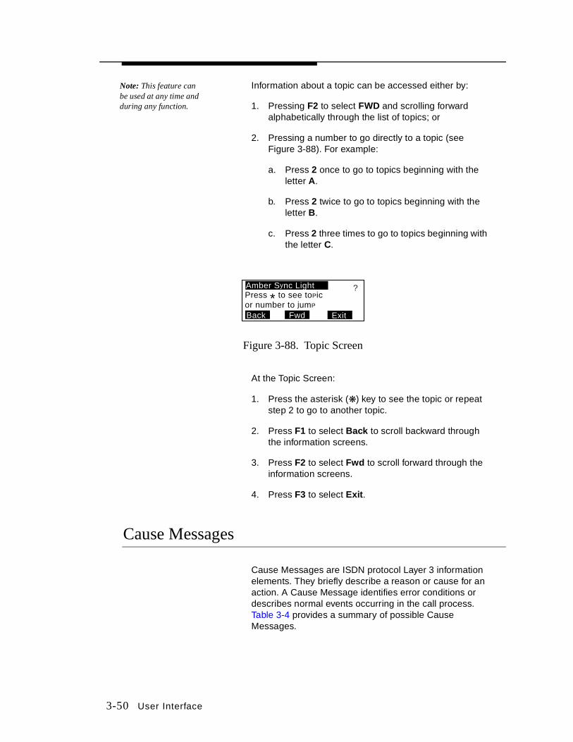
3-50 User Interface
Note: This feature can be used at any time and during any function.
Information about a topic can be accessed either by:
1. Pressing F2 to select FWD and scrolling forward alphabetically through the list of topics; or
2. Pressing a number to go directly to a topic (see Figure 3-88). For example:
a. Press 2 once to go to topics beginning with the letter A.
b. Press 2 twice to go to topics beginning with the letter B.
c. Press 2 three times to go to topics beginning with the letter C.
Figure 3-88. Topic Screen
At the Topic Screen:
1. Press the asterisk (❋) key to see the topic or repeat step 2 to go to another topic.
2. Press F1 to select Back to scroll backward through the information screens.
3. Press F2 to select Fwd to scroll forward through the information screens.
4. Press F3 to select Exit.
Cause Messages
Cause Messages are ISDN protocol Layer 3 information elements. They briefly describe a reason or cause for an action. A Cause Message identifies error conditions or describes normal events occurring in the call process. Table 3-4 provides a summary of possible Cause Messages.
ExitBack Fwd
Amber Sync LightPress * to see toPicor number to jumP
?

User Interface 3-51
Table 3-4. Cause Messages
No. Meaning No. Meaning
1 Unallocated or unassigned number. 63 Service or option not available, unspecified.
2 No route to specified transit network. 65 Bearer capability not implemented.
3 No route to destination. 66 Channel type not implemented.
6 Channel unacceptable. 69 Requested facility not implemented.
7 Call awarded and being delivered in an established channel.
70 Only restricted digital information bearer capability is available.
16 Normal call clearing. 79 Service or option not implemented, unspecified.
17 User busy. 81 Invalid call reference value.
18 No user responding. 82 Identified channel does not exist.
19 No answer from user. 83 A suspended call exists, but this call identity does not.
21 Call rejected. 84 Call identity in use.
22 Number changed. 85 No call suspended.
26 Nonselected user clearing. 86 Call once the requested call identity has been cleared.
27 Destination out of order. 88 Incompatible destination.
28 Invalid number format. 91 Invalid transit network selection.
29 Requested facility rejected. 95 Invalid message unspecified.
30 Response to STATUS ENQUIRY. 96 Mandatory information element is missing.
31 Normal, unspecified. 97 Message type nonexistent or not implemented.
34 No circuit/channel available. 98 Message not compatible with call state or message type nonexistent or not implemented.
38 Network out of order. 99 Information element nonexistent or not implemented.
41 Temporary failure. 100 Invalid information element contents.
42 Switching equipment congestion. 101 Message not compatible with call state.
43 Access information discarded. 102 Recovery on timer expired.

3-52 User Interface
Table 3-4. Cause Messages (Continued)
To access information about a Cause Message:
1. When a Cause Message occurs, it is displayed on the LCD (see Figure 3-89), press the Assist key to retrieve information about the Cause Message.
2. Press F2 to select Fwd to scroll forward through the Information Screens. Information about the Cause Message is displayed on succeeding screens (see Figure 3-89) until the entire message is displayed.
3. Press F1 to select Back to scroll back through the Cause Message Information Screens.
4. Press F3 to select Exit back to the initial Cause Message Information Screen (see Figure 3-89).
5. Press F3 to select Clear.
No. Meaning No. Meaning
44 Requested circuit/channel not available.
111 Protocol error, unspecified.
47 Resources unavailable, unspecified. 112 Progress in-band.
49 Quality of service unavailable. 113 Invalid SPID value.
50 Requested facility not subscribed. 115 Terminal unregistered.
57 Bearer capability not authorized. 127 Interworking, unspecified.
58 Bearer capability not presently available.
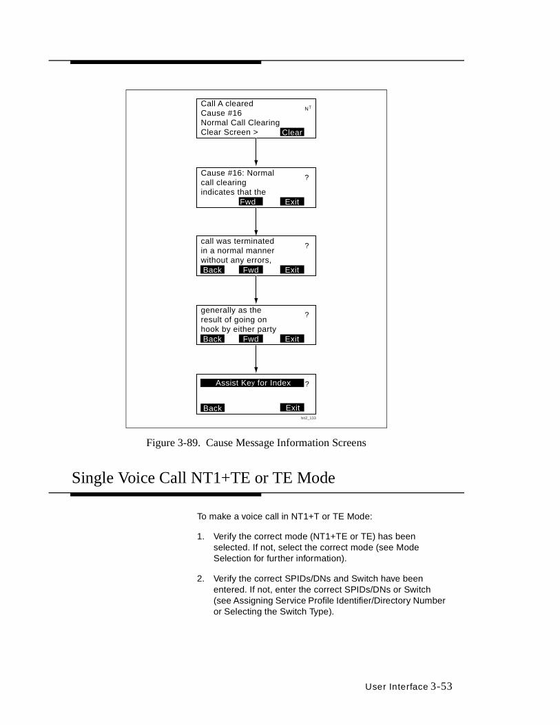
User Interface 3-53
Figure 3-89. Cause Message Information Screens
Single Voice Call NT1+TE or TE Mode
To make a voice call in NT1+T or TE Mode:
1. Verify the correct mode (NT1+TE or TE) has been selected. If not, select the correct mode (see Mode Selection for further information).
2. Verify the correct SPIDs/DNs and Switch have been entered. If not, enter the correct SPIDs/DNs or Switch (see Assigning Service Profile Identifier/Directory Number or Selecting the Switch Type).
Call A clearedCause #16Normal Call ClearingClear Screen > Clear
NT
Cause #16: Normalcall clearingindicates that the
Exit
?
generally as theresult of going onhook by either party
Exit
Exit
?
Fwd
Back Fwd
?
Back
Assist Key for Index
call was terminatedin a normal mannerwithout any errors,
Exit
?
FwdBack
bit2_133
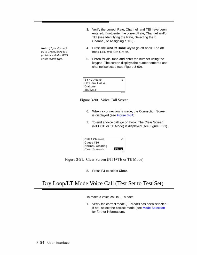
3-54 User Interface
3. Verify the correct Rate, Channel, and TEI have been entered. If not, enter the correct Rate, Channel and/or TEI (see Identifying the Rate, Selecting the B Channel, or Assigning a TEI).
Note: If Sync does not go to Green, there is a problem with the SPID or the Switch type.
4. Press the On/Off Hook key to go off hook. The off hook LED will turn Green.
5. Listen for dial tone and enter the number using the keypad. The screen displays the number entered and channel selected (see Figure 3-90).
Figure 3-90. Voice Call Screen
6. When a connection is made, the Connection Screen is displayed (see Figure 3-34).
7. To end a voice call, go on hook. The Clear Screen (NT1+TE or TE Mode) is displayed (see Figure 3-91).
Figure 3-91. Clear Screen (NT1+TE or TE Mode)
8. Press F3 to select Clear.
Dry Loop/LT Mode Voice Call (Test Set to Test Set)
To make a voice call in LT Mode:
1. Verify the correct mode (LT Mode) has been selected. If not, select the correct mode (see Mode Selection for further information).
SYNC ActiveOff Hook Call ADialtone3892283
NT
bit2_076
Call A ClearedCause #16Normal, ClearingClear Screen> Clear
NT
bit2_090

User Interface 3-55
2. At the LT Mode Home Screen (in Sync) (see Figure 3-32), press F2 to select Hook or press the On/Off Hook key on either test set to go off hook. The off hook LED will turn Green.
3. Go Off Hook. When the other test set rings, answer it. When a connection is made, the Connection Screen (Dry Loop) is displayed (see Figure 3-92).
Figure 3-92. Connection Screen (Dry Loop)
4. To end and clear a voice call, go back on hook. The Clear Screen (Dry Loop) is displayed (see Figure 3-93) on both test sets.
Figure 3-93. Clear Screen (Dry Loop)
Dual Voice Call
As a result of ISDN lines having multiple channels, the TS220 and TS250 Test Sets maintain calls on both B1 and B2 Channels from time to time. Because there is one set of hardware call control elements (CODEC, receiver, transmitter), managing multiple calls consists of placing one call on hold while taking the other call. When both B1 and B2 Channels are active, the user must select one or the other as the active call.
Dry Loop OperationFar End: Harris NT Call Connected
BERT Hook Auto
LT
bit2_124
Dry Loop OperationFar End: Harris LT Call Connected
BERT Hook Auto
NT
bit2_138
NT Mode Test Set LT Mode Test Set
Dry Loop OperationFar End: Harris NT Call Cleared
BERT Hook Auto
LT
bit2_123
Dry Loop OperationFar End: Harris LT Call Cleared
BERT Hook Auto
NT
bit2_140
NT Mode Test Set LT Mode Test Set

3-56 User Interface
When an incoming call occurs and there is already an active call, an abbreviated ringing tone, similar to a call waiting tone, is sounded so as to not interrupt the user's current call, yet still provide adequate notification of the incoming call.
To make a voice call:
1. Verify the correct mode (NT1+TE or TE) has been selected. If not, select the correct mode (see Mode Selection for further information).
2. Verify the correct SPIDs/DNs and Switch have been entered. If not, enter the correct SPIDS/DNs or Switch (see Assigning Service Profile Identifier/Directory Number or Selecting the Switch Type).
3. Verify the correct Rate, Channel, and TEI have been entered. If not, enter the correct Rate, Channel and/or TEI (see Identifying the Rate, Selecting the B Channel, or Assigning a TEI).
Note: If Sync does not go to Green, there is a problem with the SPID or the Switch type.
4. Press the On/Off Hook to go off hook. The off hook LED will turn Green.
5. Listen for dial tone and enter the number using the keypad. LCD screen displays the number entered and channel selected (see Figure 3-90). The first call is on Call A.
6. When a connection is made, the Connection Screen is displayed (see Figure 3-34).
7. To make a call on Call B, press F3 to select GoTo B. The Dual Call Setup Screen is displayed (see Figure 3-94).
Figure 3-94. Dual Call Setup Screen
8. Verify the correct Rate has been selected. If not correct, select the correct Rate (see Identifying the Rate).
9. To go off hook on Call B, press F2 to select Hook B. The user is now able to make another call.
SYNC ActiveCall B SelectedCall B Idle
NT
Hook B GoTo ARatebit2_075
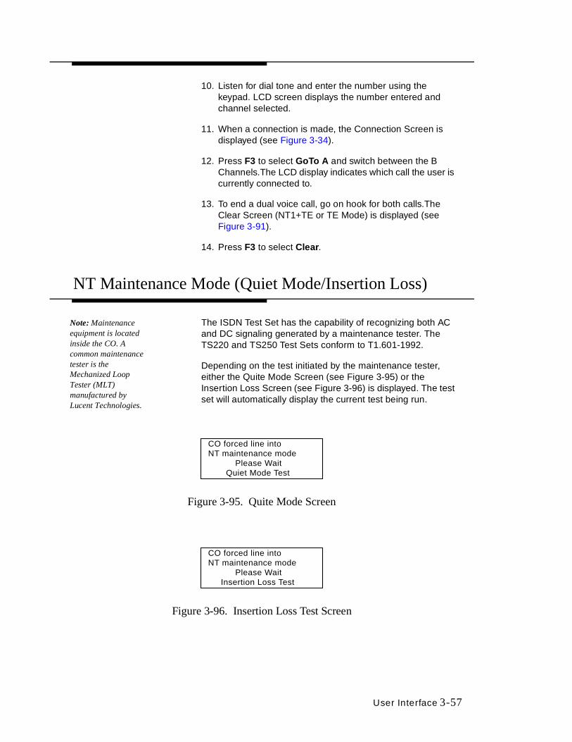
User Interface 3-57
10. Listen for dial tone and enter the number using the keypad. LCD screen displays the number entered and channel selected.
11. When a connection is made, the Connection Screen is displayed (see Figure 3-34).
12. Press F3 to select GoTo A and switch between the B Channels.The LCD display indicates which call the user is currently connected to.
13. To end a dual voice call, go on hook for both calls.The Clear Screen (NT1+TE or TE Mode) is displayed (see Figure 3-91).
14. Press F3 to select Clear.
NT Maintenance Mode (Quiet Mode/Insertion Loss)
Note: Maintenance equipment is located inside the CO. A common maintenance tester is the Mechanized Loop Tester (MLT) manufactured by Lucent Technologies.
The ISDN Test Set has the capability of recognizing both AC and DC signaling generated by a maintenance tester. The TS220 and TS250 Test Sets conform to T1.601-1992.
Depending on the test initiated by the maintenance tester, either the Quite Mode Screen (see Figure 3-95) or the Insertion Loss Screen (see Figure 3-96) is displayed. The test set will automatically display the current test being run.
Figure 3-95. Quite Mode Screen
Figure 3-96. Insertion Loss Test Screen
CO forced line intoNT maintenance mode
Please Wait Quiet Mode Test
CO forced line intoNT maintenance mode
Please Wait Insertion Loss Test

3-58 User Interface
When running Quite Mode or the Insertion Loss Measurement Test, all functions of the test are disabled. Once the test has been completed, the test set will return to its previous state.
In the Quiet Mode, the test set ceases all transmission, and does not attempt startup for approximately 75 seconds.
During the Insertion Loss Measurement Test, the test set generates a scrambled, 2B1Q frame signal for a duration of 75 seconds.
X.25 4-1
4X.25
The TS220 and TS250 Basic Rate ISDN Test Sets are capable of communication over an Integrated Services Digital Network (ISDN) using ITU X.25 formatted Layer Access Protocol D channel (LAPD) packet data (D packets). X.25 packet data calls are not supported on the B channel.
A D packet call may be originated or received by a TS220 and TS250 Test Set in NT-1/TE (Network Termination-Terminal Equipment) or TE (Terminal Equipment) modes. LT Mode does not support D packet calls.
The TS220 and TS250 Test Sets are capable of performing the following functions:
■ Call configuration.
■ Single D packet call.
■ D packet self call.
■ D packet transmission.
■ Display of received D packets.
Call Configuration
The TS220 and TS250 Test Sets accept user input and uses the following X.25 parameters:
■ Directory Number (DN).
■ User Data.
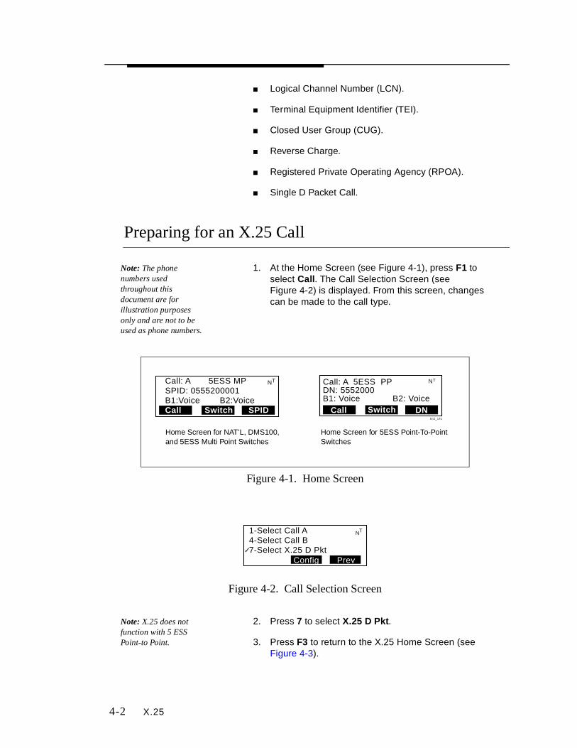
4-2 X.25
■ Logical Channel Number (LCN).
■ Terminal Equipment Identifier (TEI).
■ Closed User Group (CUG).
■ Reverse Charge.
■ Registered Private Operating Agency (RPOA).
■ Single D Packet Call.
Preparing for an X.25 Call
Note: The phone numbers used throughout this document are for il lustration purposes only and are not to be used as phone numbers.
1. At the Home Screen (see Figure 4-1), press F1 to select Call. The Call Selection Screen (see Figure 4-2) is displayed. From this screen, changes can be made to the call type.
Figure 4-1. Home Screen
Figure 4-2. Call Selection Screen
Note: X.25 does not function with 5 ESS Point-to Point.
2. Press 7 to select X.25 D Pkt.
3. Press F3 to return to the X.25 Home Screen (see Figure 4-3).
Call: A 5ESS MPSPID: 0555200001B1:Voice B2:VoiceCall Switch SPID
NT Call: A 5ESS PPDN: 5552000B1: Voice B2: Voice
Call Switch DN
NT
bit2_141
Home Screen for NAT’L, DMS100, and 5ESS Multi Point Switches
Home Screen for 5ESS Point-To-Point Switches
1-Select Call A4-Select Call B7-Select X.25 D Pkt
PrevConfig
NT

X.25 4-3
Figure 4-3. X.25 Home Screen
Assigning a Directory Number
Note: Some switch types use a specific DN that is not derived from the corresponding SPID to handle D packet calls.
The test set maintains a separate DN for D packet calls. The DN is a numeric string of up to 10 digits with a default value of empty.
To assign a DN:
1. At the X.25 Home Screen (see Figure 4-3), press F3 to select DN/LCN. The DN/LCN Setup Screen is displayed (seeFigure 4-4).
Figure 4-4. DN/LCN Setup Screen
2. Press 1 to select DN. The DN Edit Screen (see Figure 4-5) is displayed.
Figure 4-5. DN Edit Screen
3. Press F2 to select <BkSp to delete a DN shown on the display. The cursor will move backwards as it deletes the existing DN digits. Pressing and holding F2 results in repeated backspaces.
4. Enter the new DN using the keypad.
5. Press F3 to select Save and return to the previous menu.
Call: D 5ESS MPDN: 7380478X.25 Packet
DN/LCNSwitchCall
NT
LCN:1
bit2_183
1 -DN 2-LCN
PrevTEI
NT
Selected Call:D
Edit DN, Call D:7380478_
Save<BkSp
NT

4-4 X.25
Assigning a Logical Channel Number
The Logical Channel Number (LCN) is used to identify which circuit is used for D packet receipt and transmission. The test set uses one LCN per call. LCN values of 1 to 15 are valid. The default value is 1.
To assign an LCN:
1. At the DN/LCN Setup Screen (see Figure 4-4), press 2 to select LCN. The LCN Edit Screen (see Figure 4-6) is displayed.
Figure 4-6. LCN Edit Screen
2. Press F2 to select <BkSp to delete a LCN shown on the display. The cursor will move backwards as it deletes the existing LCN digits. Pressing and holding F2 results in repeated backspaces.
3. Enter the new LCN using the keypad. Only values between 1 and 15 are allowed.
4. Press F3 to select Save and return to the previous menu.
Assigning a Terminal Equipment Identifier (TEI)
The Terminal Equipment Identifier (TEI) is used by both the switch and the test set to identify the terminal that the D packet data is transmitted to or originates from. The default value is Auto. Valid values for user entry are 0 to 63 and Auto.
To enter a TEI:
1. At the DN/LCN Setup Screen (see Figure 4-4), press F2 to select TEI. The TEI Setup Screen (see Figure 4-7) is displayed.
Edit LCN:1_
1-15 are validSave<BkSp
NT

X.25 4-5
Figure 4-7. TEI Setup Screen
2. Press 1 to edit TEI. The TEI Edit Screen is displayed (see Figure 4-8).
Figure 4-8. TEI Edit Screen
3. Press F1 to select Auto. Auto will set the TEI to 127 (broadcast) and return you to the previous menu.
4. Press F2 to select <BkSp to delete a TEI shown on the display. The cursor will move backwards as it deletes the existing TEI digits. Pressing and holding F2 results in repeated backspaces.
Note: Only TEI numbers between 0 and 63 and 127 (auto) are valid.
1. Enter the new TEI using the keypad. If a change to the TEI value was made, the test set will request a D packet link for the new TEI.
2. Press F3 to select Save and return to the previous menu.
Configuring a Call
To configure a call:
1. At the X.25 Home Screen (see Figure 4-3), press F1 to select Call. The Call Selection Screen (see Figure 4-2) is displayed.
2. Press F2 to select Config. The Configuration Setup Screen is displayed (see Figure 4-9).
1-TEI Call D = 127
Prev
NT
Selected Call: D
TEI Call D127
Save<BkSpAuto
NT
0-63 are valid

4-6 X.25
Figure 4-9. Configuration Setup Screen
Closed User Group
The Closed User Group (CUG) value indicates which private user group the D packet call belongs to. If a value has been entered for the CUG, the test set may only make or receive packet calls from devices in the same CUG. The test set accepts four digit CUG values between 0 and 9999 or None, with None being the default.
To set up user groups (CUG):
1. At the Configuration Setup Screen (see Figure 4-9), press 1 to select CUG. The Closed User Group Setup Screen is displayed (see Figure 4-10).
Figure 4-10. Closed User Group Setup Screen
2. Press F1 to select None , if the CUG is not required.
3. If a CUG is required, press F2 to select <BkSp to delete a CUG shown on the display. The cursor will move backwards as it deletes the existing CUG digits. Pressing and holding F2 results in repeated backspaces.
4. Enter a new four-digit CUG number using the keypad.
5. Press F3 to select Save and return to the previous menu.
1-CUG 2-RevCharge4-RPOA 5-UserData7-DataPkt
bit2_218
NT
Prev
Closed User Group0000_
Save<BkSpNone
NT
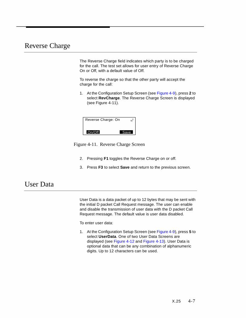
X.25 4-7
Reverse Charge
The Reverse Charge field indicates which party is to be charged for the call. The test set allows for user entry of Reverse Charge On or Off, with a default value of Off.
To reverse the charge so that the other party will accept the charge for the call:
1. At the Configuration Setup Screen (see Figure 4-9), press 2 to select RevCharge. The Reverse Charge Screen is displayed (see Figure 4-11).
Figure 4-11. Reverse Charge Screen
2. Pressing F1 toggles the Reverse Charge on or off.
3. Press F3 to select Save and return to the previous screen.
User Data
User Data is a data packet of up to 12 bytes that may be sent with the initial D packet Call Request message. The user can enable and disable the transmission of user data with the D packet Call Request message. The default value is user data disabled.
To enter user data:
1. At the Configuration Setup Screen (see Figure 4-9), press 5 to select UserData . One of two User Data Screens are displayed (see Figure 4-12 and Figure 4-13). User Data is optional data that can be any combination of alphanumeric digits. Up to 12 characters can be used.
Reverse Charge: On
SaveOn/Off
NT

4-8 X.25
Figure 4-12. User Data Screen (Digit)
Figure 4-13. User Data Screen (Alpha)
2. Press F1 to toggle between the alpha and numeric modes.
3. Press F2 to select <BkSp to delete user data shown on the display. The cursor will move backwards as it deletes the existing data. Pressing and holding F2 results in repeated backspaces.
4. To enter alpha letters (see Figure 4-13):
a. Press the number key of the letter you want to enter. Press the key once for the first letter, twice for the second letter, and three times for the third letter. Pressing 0 (zero) three times will result in a space between words.
b. Press the 1 number key to select the current character and space over to the next letter.
c. Press the asterisk (*) key to change the alpha letter from upper to lower case letters or from lower to upper case letters.
5. To enter numerical data (see Figure 4-12), enter the desired numeric digits using the keypad.
6. Press F3 to select Save and return to the previous menu.
Input Mode: DigitEnter Digits111_
Save<BkSpAI/Num
NT
Input Model: Alpha L1=Select = U/L Case111_
Save<BkSpAI/Num
NT
*

X.25 4-9
Registered Private Operating Agency
The Registered Private Operating Agency (RPOA) option is used to determine which agency will carry the D packets. The test set shall accept RPOA values between 0 and 9999 or None, with None being the default.
To select the agency that will carry the D packets (e.g., long distance service):
1. At the Configuration Setup Screen (see Figure 4-9), press 4 to select RPOA . The RPOA Screen is displayed (see Figure 4-14).
Figure 4-14. RPOA Screen
2. Press F1 to select None, if the RPOA is not required.
3. If a RPOA is required, press F2 to select <BkSp to delete a RPOA shown on the display. The cursor will move backwards as it deletes the existing RPOA digits. Pressing and holding F2 results in repeated backspaces.
4. Enter a new four-digit RPOA number using the keypad.
5. Press F3 to select Save and return to the previous screen.
Data Packet
The Data Packet (DataPkt) option is used to select the size of the data packet that will be transmitted and the terminating sequence of the data. Some networks do not allow for more than 16 or 32 bytes.
To select or change the size of the data packet:
1. At the Configuration Setup Screen (see Figure 4-9), press 7 to select DataPkt . The DataPkt Screen is displayed (see Figure 4-15).
Registered PrivateOperating Agency0000_
Save<BkSpNone
NT
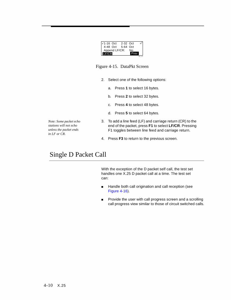
4-10 X.25
Figure 4-15. DataPkt Screen
2. Select one of the following options:
a. Press 1 to select 16 bytes.
b. Press 2 to select 32 bytes.
c. Press 4 to select 48 bytes.
d. Press 5 to select 64 bytes.
Note: Some packet echo stations will not echo unless the packet ends in LF or CR.
3. To add a line feed (LF) and carriage return (CR) to the end of the packet, press F1 to select LF/CR. Pressing F1 toggles between line feed and carriage return.
4. Press F3 to return to the previous screen.
Single D Packet Call
With the exception of the D packet self call, the test set handles one X.25 D packet call at a time. The test set can:
■ Handle both call origination and call reception (see Figure 4-16).
■ Provide the user with call progress screen and a scrolling call progress view similar to those of circuit switched calls.
1-16 Oct 2-32 Oct4-48 Oct 5-64 OctAppend LF/CR: No
Prevbit2_214
NT
LF/CR
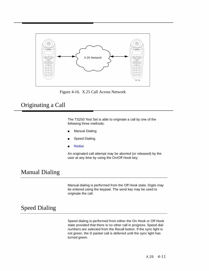
X.25 4-11
Figure 4-16. X.25 Call Across Network
Originating a Call
The TS250 Test Set is able to originate a call by one of the following three methods:
■ Manual Dialing.
■ Speed Dialing.
■ Redial.
An originated call attempt may be aborted (or released) by the user at any time by using the On/Off Hook key.
Manual Dialing
Manual dialing is performed from the Off Hook state. Digits may be entered using the keypad. The send key may be used to originate the call.
Speed Dialing
Speed dialing is performed from either the On Hook or Off Hook state provided that there is no other call in progress. Speed dial numbers are selected from the Recall button. If the sync light is not green, the D packet call is deferred until the sync light has turned green.
X.25 Network
bit2_196
Sync OffHook Volt
Chg
2ABC1 3DEF
4GHI 5JKL 6MNO
7PRS 8TUV 9WXY
0QZ
LNR
Menu
On/OffHook
Assist
Power
Light
Recall
Spkr Mute
Sync OffHook Volt
Chg
2ABC1 3DEF
4GHI 5JKL 6MNO
7PRS 8TUV 9WXY
0QZ
LNR
Menu
On/OffHook
Assist
Power
Light
Recall
Spkr Mute
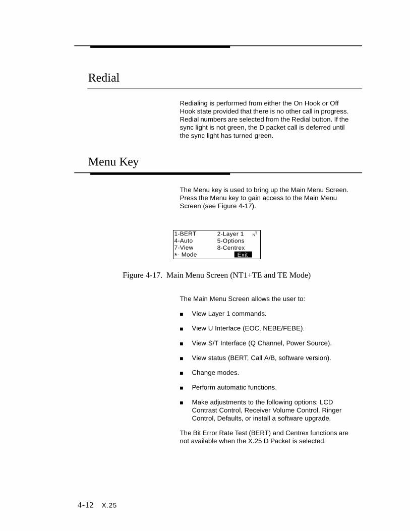
4-12 X.25
Redial
Redialing is performed from either the On Hook or Off Hook state provided that there is no other call in progress. Redial numbers are selected from the Redial button. If the sync light is not green, the D packet call is deferred until the sync light has turned green.
Menu Key
The Menu key is used to bring up the Main Menu Screen. Press the Menu key to gain access to the Main Menu Screen (see Figure 4-17).
Figure 4-17. Main Menu Screen (NT1+TE and TE Mode)
The Main Menu Screen allows the user to:
■ View Layer 1 commands.
■ View U Interface (EOC, NEBE/FEBE).
■ View S/T Interface (Q Channel, Power Source).
■ View status (BERT, Call A/B, software version).
■ Change modes.
■ Perform automatic functions.
■ Make adjustments to the following options: LCD Contrast Control, Receiver Volume Control, Ringer Control, Defaults, or install a software upgrade.
The Bit Error Rate Test (BERT) and Centrex functions are not available when the X.25 D Packet is selected.
1-BERT4-Auto7-View
*- Mode
2-Layer 15-Options8-Centrex
Exit
NT

X.25 4-13
Auto
Note: For the Auto Function to work, the line under test must support two logical channels.
To perform an Auto function call:
1. At the Main Menu Screen (see Figure 4-17), press 4 to select Auto. The Incoming Call Screen is displayed (see Figure 4-18). The call will be automatically answered and the caller ID will be displayed (see Figure 4-19).
Figure 4-18. Incoming Call Screen
Figure 4-19. Caller ID Screen
2. Press F2 to select Tx Pkt . The test set will increment the total number of packets (TX:00) that have been transmitted (see Figure 4-20). The counter will roll over at 99. The packet received is shown in Figure 4-20. If the packet is correctly passed through the network, the display will contain the packet number followed by a colon (:) and the phrase shown in Figure 4-20.
Figure 4-20. Tx Pkt Information Screen
Sync ActiveIncoming Call D1-805-738-0494
NT
1-805-738-0494X.25 CallerCall Yourself: X.25TX: 00 ResetTx Pkt
NT
D
bit2_168
ResetTx Pkt
01: The quick brownfox jumps over thelazy dog.TX:01
NT
D
bit2_175

4-14 X.25
3. Press F3 to select Reset . The Reset Screen is displayed (see Figure 4-21). Reset causes the counter to reset to zero and all X.25 protocol counters to be reset. Reset may be used to force the sender and receiver to resynchronize.
Figure 4-21. Reset Screen
4. Press the On/Off Ho ok Key. The Call is released and the Clear Screen is displayed (see Figure 4-21).
Figure 4-22. Clear Screen
5. Press F3 to select Clear and return to the X.25 Home screen.
View
The View function key stores information on the last call attempt that took place on Call A, Call B, and/or Call D. View also provides the results of previous BERTs, previous results from self tests, and the current version of software being used in the test set.
To access the View Screen in X.25 (see Figure 4-23):
1. At the Main Menu Screen (see Figure 4-17), press 7 to select View. The View Screen is displayed (see Figure 4-23).
lazy dog.Call D ResetDTE OriginatedTX: 00 ResetTx Pkt
NT
D
Call D ClearedDTE OriginatedCall D ClearedClear Screen > Clear
NT
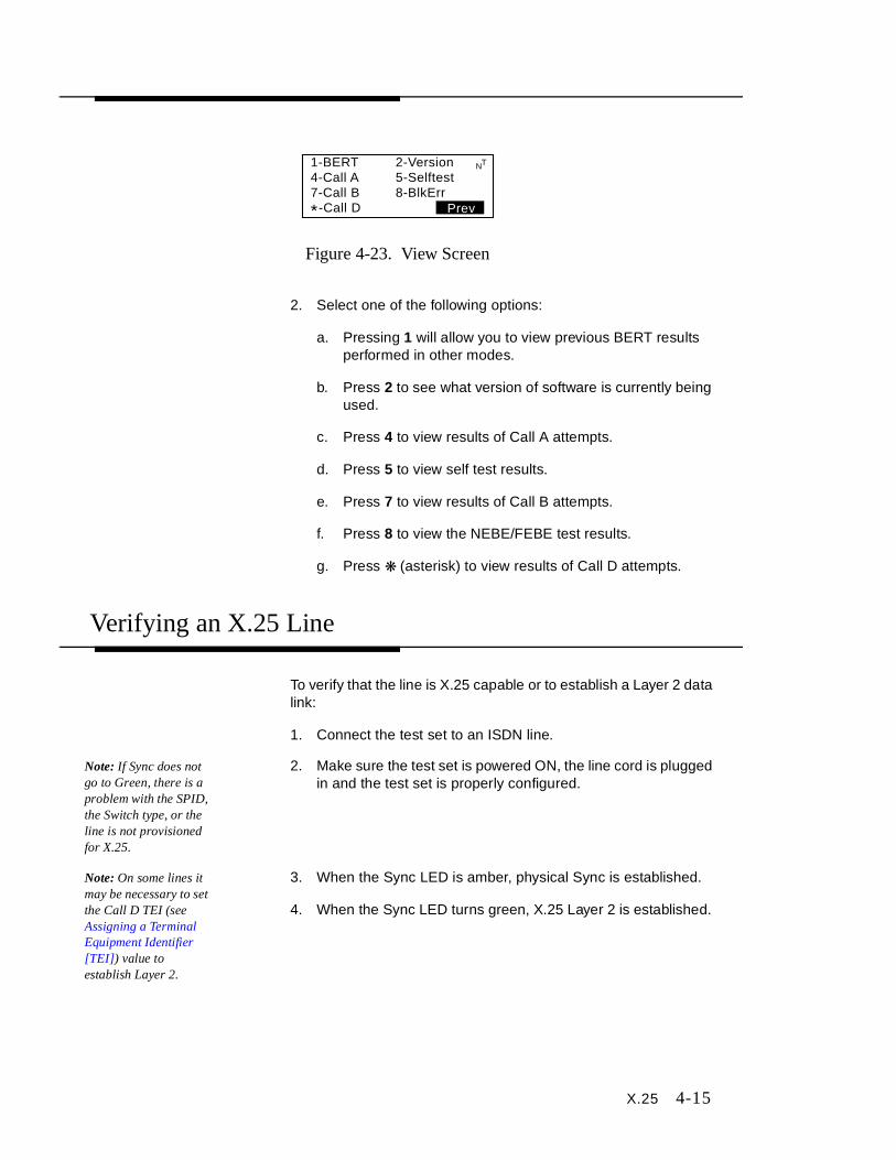
X.25 4-15
Figure 4-23. View Screen
2. Select one of the following options:
a. Pressing 1 will allow you to view previous BERT results performed in other modes.
b. Press 2 to see what version of software is currently being used.
c. Press 4 to view results of Call A attempts.
d. Press 5 to view self test results.
e. Press 7 to view results of Call B attempts.
f. Press 8 to view the NEBE/FEBE test results.
g. Press ❋ (asterisk) to view results of Call D attempts.
Verifying an X.25 Line
To verify that the line is X.25 capable or to establish a Layer 2 data link:
1. Connect the test set to an ISDN line.
Note: If Sync does not go to Green, there is a problem with the SPID, the Switch type, or the line is not provisioned for X.25.
2. Make sure the test set is powered ON, the line cord is plugged in and the test set is properly configured.
Note: On some lines it may be necessary to set the Call D TEI (see Assigning a Terminal Equipment Identifier [TEI]) value to establish Layer 2.
3. When the Sync LED is amber, physical Sync is established.
4. When the Sync LED turns green, X.25 Layer 2 is established.
1-BERT4-Call A7-Call B -Call D
2-Version5-Selftest8-BlkErr
Prev
NT
*
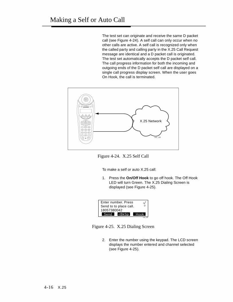
4-16 X.25
Making a Self or Auto Call
The test set can originate and receive the same D packet call (see Figure 4-24). A self call can only occur when no other calls are active. A self call is recognized only when the called party and calling party in the X.25 Call Request message are identical and a D packet call is originated. The test set automatically accepts the D packet self call. The call progress information for both the incoming and outgoing ends of the D packet self call are displayed on a single call progress display screen. When the user goes On Hook, the call is terminated.
Figure 4-24. X.25 Self Call
To make a self or auto X.25 call:
1. Press the On/Off Hook to go off hook. The Off Hook LED will turn Green. The X.25 Dialing Screen is displayed (see Figure 4-25).
Figure 4-25. X.25 Dialing Screen
2. Enter the number using the keypad. The LCD screen displays the number entered and channel selected (see Figure 4-25).
X.25 Network
bit2_195
Sync OffHook Volt
Chg
2ABC1 3DEF
4GHI 5JKL 6MNO
7PRS 8TUV 9WXY
0QZ
LNR
Menu
On/OffHook
Assist
Power
Light
Recall
Spkr Mute
Enter number. PressSend to to place call.18057380042
Hook<BkSpSend
NT
D
bit2_194
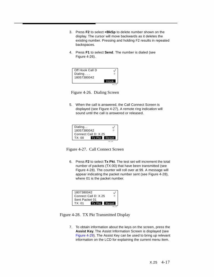
X.25 4-17
3. Press F2 to select <BkSp to delete number shown on the display. The cursor will move backwards as it deletes the existing number. Pressing and holding F2 results in repeated backspaces.
4. Press F1 to select Send. The number is dialed (see Figure 4-26).
Figure 4-26. Dialing Screen
5. When the call is answered, the Call Connect Screen is displayed (see Figure 4-27). A remote ring indication will sound until the call is answered or released.
Figure 4-27. Call Connect Screen
6. Press F2 to select Tx Pkt . The test set will increment the total number of packets (TX:00) that have been transmitted (see Figure 4-28). The counter will roll over at 99. A message will appear indicating the packet number sent (see Figure 4-28), where 01 is the packet number.
Figure 4-28. TX Pkt Transmitted Display
7. To obtain information about the keys on the screen, press the Assist Key. The Assist Information Screen is displayed (see Figure 4-29). The Assist Key can be used to bring up relevant information on the LCD for explaining the current menu item.
Hook
Off Hook Call DDialing . . .18057380042
NT
D
bit2_176
Dialing...18057380042Connect Call D: X.25TX: 00 ResetTx Pkt
NT
D
bit2_165
1807380042Connect Call D: X.25Sent Packet 01TX: 01 ResetTx Pkt
NT
D
bit2_166
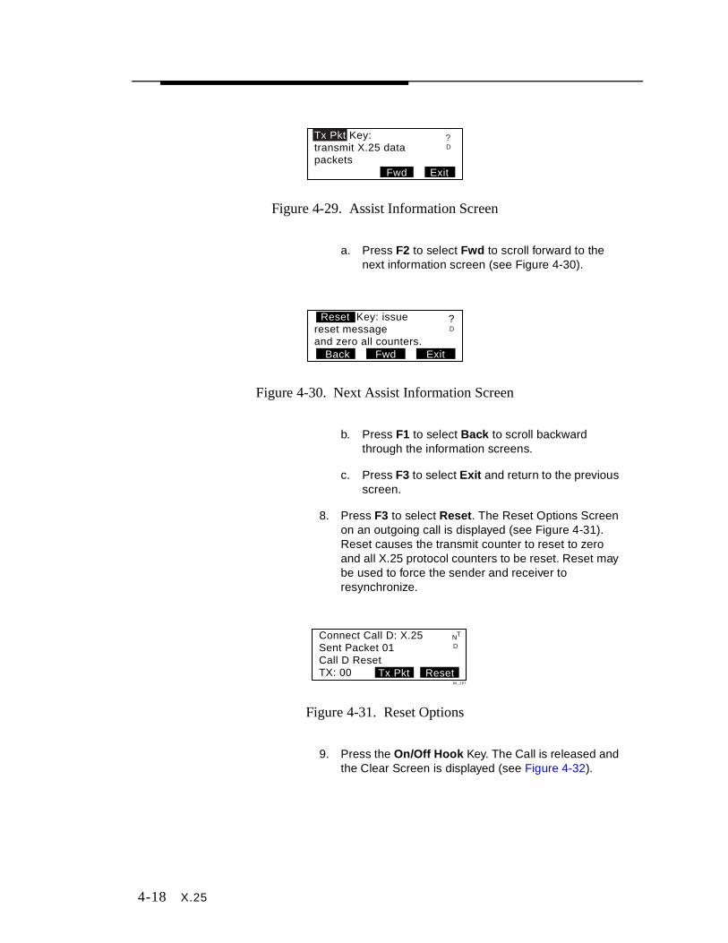
4-18 X.25
Figure 4-29. Assist Information Screen
a. Press F2 to select Fwd to scroll forward to the next information screen (see Figure 4-30).
Figure 4-30. Next Assist Information Screen
b. Press F1 to select Back to scroll backward through the information screens.
c. Press F3 to select Exit and return to the previous screen.
8. Press F3 to select Reset . The Reset Options Screen on an outgoing call is displayed (see Figure 4-31). Reset causes the transmit counter to reset to zero and all X.25 protocol counters to be reset. Reset may be used to force the sender and receiver to resynchronize.
Figure 4-31. Reset Options
9. Press the On/Off Ho ok Key. The Call is released and the Clear Screen is displayed (see Figure 4-32).
Tx Pkt Key:transmit X.25 datapackets
ExitFwd
D?
ExitFwdBack
Reset Key: issuereset messageand zero all counters.
?D
Connect Call D: X.25Sent Packet 01Call D ResetTX: 00 ResetTx Pkt
NT
D
bit_167
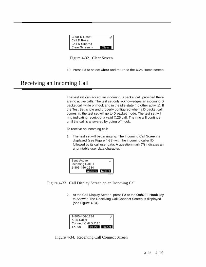
X.25 4-19
Figure 4-32. Clear Screen
10. Press F3 to select Clear and return to the X.25 Home screen.
Receiving an Incoming Call
The test set can accept an incoming D packet call, provided there are no active calls. The test set only acknowledges an incoming D packet call while on hook and in the idle state (no other activity). If the Test Set is idle and properly configured when a D packet call comes in, the test set will go to D packet mode. The test set will ring indicating receipt of a valid X.25 call. The ring will continue until the call is answered by going off hook.
To receive an incoming call:
1. The test set will begin ringing. The Incoming Call Screen is displayed (see Figure 4-33) with the incoming caller ID followed by its call user data. A question mark (?) indicates an unprintable user data character.
Figure 4-33. Call Display Screen on an Incoming Call
2. At the Call Display Screen, press F2 or the On/OFF Hook key to Answer. The Receiving Call Connect Screen is displayed (see Figure 4-34).
Figure 4-34. Receiving Call Connect Screen
Clear D ResetCall D ResetCall D ClearedClear Screen > Clear
NT
Sync ActiveIncoming Call D1-805-456-1234
RejectAnswer
NT
bit2_171
1-805-456-1234X.25 CallerConnect Call D:X.25TX: 00
NT
ResetTx Pkt
D
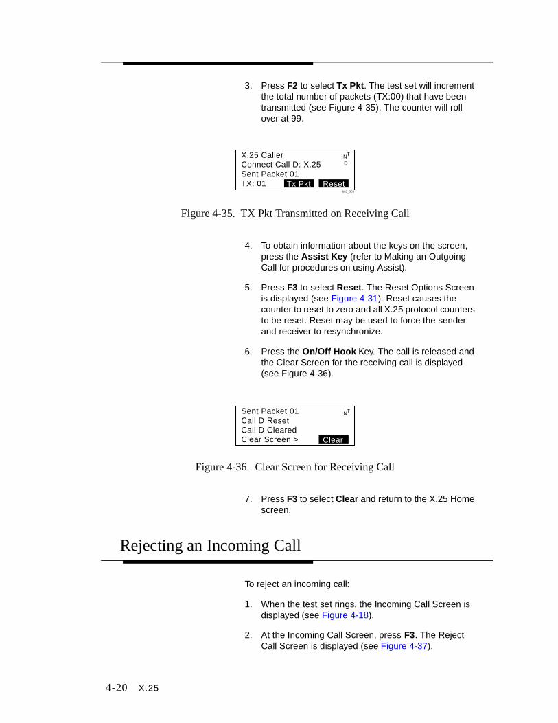
4-20 X.25
3. Press F2 to select Tx Pkt. The test set will increment the total number of packets (TX:00) that have been transmitted (see Figure 4-35). The counter will roll over at 99.
Figure 4-35. TX Pkt Transmitted on Receiving Call
4. To obtain information about the keys on the screen, press the Assist K ey (refer to Making an Outgoing Call for procedures on using Assist).
5. Press F3 to select Reset . The Reset Options Screen is displayed (see Figure 4-31). Reset causes the counter to reset to zero and all X.25 protocol counters to be reset. Reset may be used to force the sender and receiver to resynchronize.
6. Press the On/Off Ho ok Key. The call is released and the Clear Screen for the receiving call is displayed (see Figure 4-36).
Figure 4-36. Clear Screen for Receiving Call
7. Press F3 to select Clear and return to the X.25 Home screen.
Rejecting an Incoming Call
To reject an incoming call:
1. When the test set rings, the Incoming Call Screen is displayed (see Figure 4-18).
2. At the Incoming Call Screen, press F3. The Reject Call Screen is displayed (see Figure 4-37).
X.25 CallerConnect Call D: X.25Sent Packet 01TX: 01 ResetTx Pkt
NT
D
bit2_203
Sent Packet 01Call D ResetCall D ClearedClear Screen > Clear
NT

X.25 4-21
Figure 4-37. Reject Call Screen
3. Press F3 to select Clear and return to the X.25 Home screen.
Incoming Call D1-805-738-0042Call D RejectedClear Screen > Clear
NT
bit2_174

Maintenance 5-1
5Maintenance
General Care
Line Cord
Line cords are usually wrapped around the body of the test set and clipped through the belt clip when not in use. The line cords are the most used part of test set and care must be taken when unwinding the cord. Prolonged wear and tear can cause small openings and allow moisture to penetrate the cord. This is the largest source of static and noise. Changing the line cord on a regular basis can prevent this.
Keypad
Daily use of your test set results in various liquids, dirt, and other foreign material building up in your keypad. The keypad may be cleaned by using a soft toothbrush with soap and water. Do not use a petroleum-based cleaning agent as it will harm the keypad.
CAUTION : Do not use CRC Cable Clean® or any similar chlorinated solvent on the TS220 or TS250 Test Set. Doing so will damage the Test Set.

5-2 Maintenance
Belt Clip
A Test Set’s belt clip is in constant use and can wear out with prolonged use. Belt clips are field replaceable and easily changed when they become loose.
Battery
A low battery condition is indicated to the user through the use of a Low Battery icon on the LCD (see Figure 5-1). A flashing icon indicates the test set has reached its first warning level. When the Low Battery icon appears on the LCD display, you have approximately 30 minutes of operating time left before the test set automatically powers off. The second level occurs when the icon is solid. At this level, the test set is not functional.
The battery icon blinks on and off when the test set is about to power itself down.
Figure 5-1. Low Battery Icon
If the test set is operated in rain, remove the battery door and make sure the inside of the unit is dry. if necessary, blow dry the inside of the test set.
Safety Precautions
To reduce the risk of fire or injury, read and follow these instructions when recharging, replacing, or otherwise handling the batteries for the TS220 or TS250 Test Set:
■ DO NOT mix batteries of different types, sizes, or from different manufacturers in this product.
■ DO NOT mix old and new batteries in this product.
Maintenance 5-3
■ DO NOT dispose of batteries in a fire. The batteries may explode. Check with local codes for special instructions.
■ DO NOT attempt to recharge Alkaline batteries. The batteries may leak corrosive electrolyte or explode.
■ DO NOT open or mutilate the batteries. Released battery electrolyte is corrosive and may cause damage to the eyes or skin. Released electrolyte may be toxic and can cause poisoning if swallowed.
■ Exerc ise care in handling the batteries to avoid shorting batteries with conducting materials such as rings, bracelets, or keys. The battery or shorting conductor could overheat and cause burns.
■ Remove the batteries from the TS220 or TS250 Test Set if you do not plan to use it for a long period of time (60 days or more). Batteries could leak in the Test Set during Iong-term storage.
Charging the NiCad Batteries
Normally, the TS220 or TS250 Test Set is powered by the NiCad batteries supplied with the instrument.
To prolong the life of the batteries, use the adapter/charger to power the unit while the batteries are installed. Only the NiCad batteries automatically charge whenever the AC adapter/charger is connected.
To charge the NiCad batteries:
1. Connect the AC adapter/charger to the TS220 or TS250 Test Set (see Figure 5-2).
2. Plug the AC adapter/charger into a 120 VAC wall plug (ordinary household current).
3. During fast charge mode, a yellow LED will come on.
4. When fast charge is complete, the test set switches to trickle charge mode and the LED will change from yellow to green. The unit will remain in trickle charge until DC power is removed.

5-4 Maintenance
Figure 5-2. Using the AC Adapter
Battery Replacement
Use only the following type and size of batteries:
■ 4 NiCad rechargeable batteries supplied with the TS220 or TS250 Test Set.
■ 4 AA-size alkaline batteries.
To replace the batteries:
1. Turn the TS220 or TS250 Test Set off and disconnect the AC adapter/charger from the Test Set, if attached (see Figure 5-3).
2. Place the TS220 or TS250 Test Set on a protected work surface, face down.
Note: Cover screws are not removable.
3. Using a flat-blade screwdriver, loosen the four screws attaching the battery door cover to the back of the TS220 or TS250 Test Set (see Figure 5-4).
4. Remove the battery door cover (see Figure 5-5).
5. Remove the old batteries from the TS220 or TS250 Test Set (see Figure 5-6) and properly discard.

Maintenance 5-5
Figure 5-3. Removing the Adapter
Figure 5-4. Rear View of Test Set
Figure 5-5. Test Set Door Cover

5-6 Maintenance
Figure 5-6. Removing the Batteries
6. Insert 4 new NiCad batteries into the TS220 or TS250 Test Set. When inserting batteries, observe the proper polarity or direction for all batteries. Reverse insertion of one or more batteries can create a charging circuit for the other batteries, which may result in leakage or explosion. Place the batteries in the compartment so that their positive contacts point towards the plus (+) symbol.
7. If replacing NiCad batteries with Alkaline batteries, first pull the movable wall out of its slot (see Figure 5-7) and move the wall forward to the first slot. Make sure the wall fits correctly into the slot. Be careful not to break the leads of the white cable ribbon behind the wall.
8. Insert new Alkaline batteries.
Note: Failure to securely fasten battery door, could result in the batteries not charging.
9. Place the battery door cover on the TS220 or TS250 Test Set (see Figure 5-5) and fasten the four screws securely (see Figure 5-4).
10. Turn the Test Set over and turn the Power button ON.
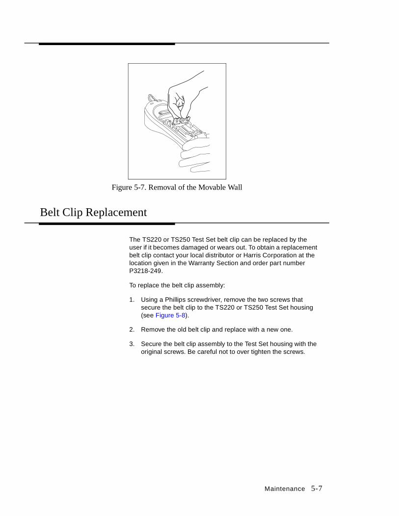
Maintenance 5-7
Figure 5-7. Removal of the Movable Wall
Belt Clip Replacement
The TS220 or TS250 Test Set belt clip can be replaced by the user if it becomes damaged or wears out. To obtain a replacement belt clip contact your local distributor or Harris Corporation at the location given in the Warranty Section and order part number P3218-249.
To replace the belt clip assembly:
1. Using a Phillips screwdriver, remove the two screws that secure the belt clip to the TS220 or TS250 Test Set housing (see Figure 5-8).
2. Remove the old belt clip and replace with a new one.
3. Secure the belt clip assembly to the Test Set housing with the original screws. Be careful not to over tighten the screws.

5-8 Maintenance
Figure 5-8. Replacing the Belt Clip
Line Cord Replacement
The line cord can be replaced by the user. To obtain a replacement line cord contact your local distributor or Harris Corporation at the location given in the Warranty Section and order part number P3218-234.
Removing the Line Cord
To remove the old line cord:
1. Turn the TS220 or TS250 Test Set off and disconnect the AC adapter/charger from the Test Set, if attached (see Figure 5-3).
2. Place the TS220 or TS250 Test Set on a protected work surface, face down.
Note: Cover screws are not removable.
3. Using a flat-blade screwdriver, loosen the four screws attaching the battery door cover to the back of the Test Set (see Figure 5-4).
4. Remove the battery door cover (see Figure 5-5).
5. Remove one battery on each side of the line cord relief strap.

Maintenance 5-9
6. Using a screwdriver or needlenose pliers, pry up the plastic clip (see Figure 5-9) that holds the line cord relief strap in place and remove clip (see Figure 5-10).
Figure 5-9. Prying Up the Plastic Clip
Figure 5-10. Removal/Installation of the Plastic Clip
7. Disconnect the RJ-45 modular connector from housing on TS220 or TS250 Test Set (see Figure 5-11).
8. Slip the line cord out through the hole in the end of the TS220 or TS250 Test Set.

5-10 Maintenance
Figure 5-11. Removal/Installation of Connector
Line Cord Installation
To install a new line cord:
1. Carefully slide the modular connector of a new line cord through the hole in the end of the TS220 or TS250 Test Set. Do not damage the connector pins or plastic tab.
2. Lay the line cord inside the groove in the bottom of the TS220 or TS250 Test Set housing (see Figure 5-12).
3. Connect the RJ-45 modular connector of the line cord in the housing on the TS220 or TS250 Test Set (see Figure 5-11).
Figure 5-12. Placement of Line Cord
Maintenance 5-11
4. Insert the plastic clip over the line cord strain relief at the base of the TS220 or TS250 Test Set housing (see Figure 5-10) and snap tightly into place.
5. Replace the previously removed batteries on each side of the line cord strain relief.
6. Place the battery door cover (see Figure 5-5) on the TS220 or TS250 Test Set and fasten the four screws (see Figure 5-4).
Warranty
Harris warrants that the TS220 or TS250 Test Set shall be free of any defects in parts or workmanship, for a period of 18 months from date of manufacture and the line cord for a period of 90 days from the date of purchase, if used under Harris operating specifications.
THIS IS THE ONLY WARRANTY MADE BY HARRIS CORPORATION AND IS MADE EXPRESSLY IN LIEU OF ALL OTHER WARRANTIES EXPRESSED OR IMPLIED, INCLUDING BUT NOT LIMITED TO ANY IMPLIED WARRANTIES OF MERCHANTABILITY OR FITNESS FOR ANY PARTICULAR PURPOSE.
Should any parts or workmanship prove defective, Harris will repair with “not used” or reconditioned parts, or replace the Product, at Harris’ option, at no cost to the Buyer except for shipping costs from the Buyer’s location to Harris’ location. This is the Buyer’s SOLE AND EXCLUSIVE REMEDY under the agreement.
All incidental or consequential damages shall be excluded.
This warranty does not extend to products which have been subjected to neglect, accident or improper use, nor to units which have been altered or repaired by other than authorized Harris personnel.
5-12 Maintenance
Return of Equipment
To return the Test Telephone to Harris, first obtain a Return Authorization (RA) Number from our Customer Service. This RA number must be clearly marked on the shipping label, or the container will not be accepted by Harris. See the sample label below:
To: HARRIS CORPORATION809 Calle PlanoCamarillo, California, USA 93012-8516Attention: Customer Support, RA #XXXXXX


![3GPP TS 32.215 V4.9 · [14] ITU-T Recommendation Q.767: "Application of the ISDN user part of CCITT signalling System No.7 for international ISDN interconnections". [15] 3GPP TS 23.040:](https://img.pdfslide.net/doc/110x75/5fb338c9a8c8973e32450f97/3gpp-ts-32215-v49-14-itu-t-recommendation-q767-application-of-the-isdn.jpg)