Embed Size (px)
Citation preview
G4HUP © 2014
PAT Install TS440S 11 Jul 2014
G4HUP Panoramic Adaptor Installation – TS440S
1. Build and test the PAT kit – use an 8v supply and you should measure a gain
of a few dB at 45MHz.
2. Remove the front bottom cover from TS440S - 5 screws on the bottom and
2 per side. There is no need to remove the carrying handle from the cover. Remove the rear bottom cover (3 screws) to access the LPF compartment
3. The best route for the output cable is through the LPF compartment and out via one of the ventilation holes. There is no sensible place to mount an SMA
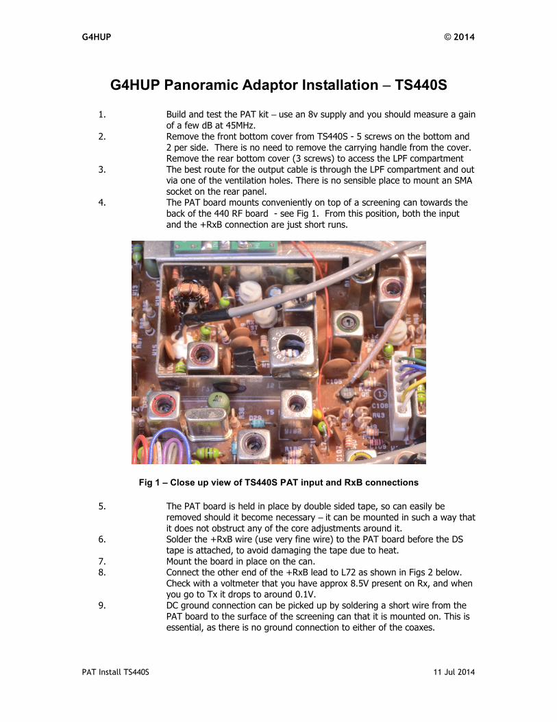
socket on the rear panel. 4. The PAT board mounts conveniently on top of a screening can towards the
back of the 440 RF board - see Fig 1. From this position, both the input
and the +RxB connection are just short runs.
Fig 1 – Close up view of TS440S PAT input and RxB connections
5. The PAT board is held in place by double sided tape, so can easily be
removed should it become necessary – it can be mounted in such a way that
it does not obstruct any of the core adjustments around it. 6. Solder the +RxB wire (use very fine wire) to the PAT board before the DS
tape is attached, to avoid damaging the tape due to heat.
7. Mount the board in place on the can. 8. Connect the other end of the +RxB lead to L72 as shown in Figs 2 below.
Check with a voltmeter that you have approx 8.5V present on Rx, and when you go to Tx it drops to around 0.1V.
9. DC ground connection can be picked up by soldering a short wire from the
PAT board to the surface of the screening can that it is mounted on. This is essential, as there is no ground connection to either of the coaxes.
G4HUP © 2014
PAT Install TS440S 11 Jul 2014
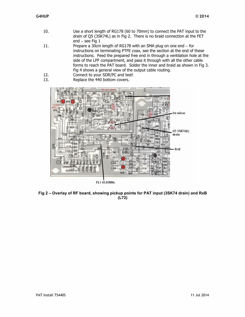
10. Use a short length of RG178 (60 to 70mm) to connect the PAT input to the
drain of Q5 (3SK74L) as in Fig 2. There is no braid connection at the FET end – see Fig 1
11. Prepare a 30cm length of RG178 with an SMA plug on one end – for
instructions on terminating PTFE coax, see the section at the end of these
instructions. Feed the prepared free end in through a ventilation hole at the side of the LPF compartment, and pass it through with all the other cable
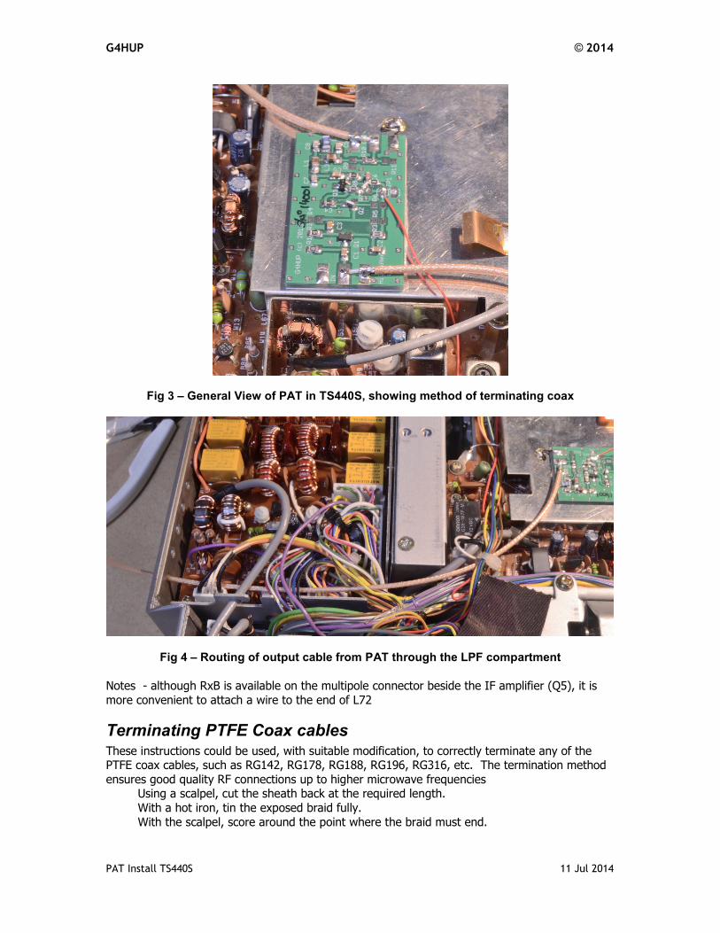
forms to reach the PAT board. Solder the inner and braid as shown in Fig 3.
Fig 4 shows a general view of the output cable routing. 12. Connect to your SDR/PC and test!
13. Replace the 440 bottom covers.
Fig 2 – Overlay of RF board, showing pickup points for PAT input (3SK74 drain) and RxB
(L72)
G4HUP © 2014
PAT Install TS440S 11 Jul 2014
Fig 3 – General View of PAT in TS440S, showing method of terminating coax
Fig 4 – Routing of output cable from PAT through the LPF compartment
Notes - although RxB is available on the multipole connector beside the IF amplifier (Q5), it is
more convenient to attach a wire to the end of L72
Terminating PTFE Coax cables These instructions could be used, with suitable modification, to correctly terminate any of the PTFE coax cables, such as RG142, RG178, RG188, RG196, RG316, etc. The termination method
ensures good quality RF connections up to higher microwave frequencies Using a scalpel, cut the sheath back at the required length.
With a hot iron, tin the exposed braid fully.
With the scalpel, score around the point where the braid must end.
G4HUP © 2014
PAT Install TS440S 11 Jul 2014
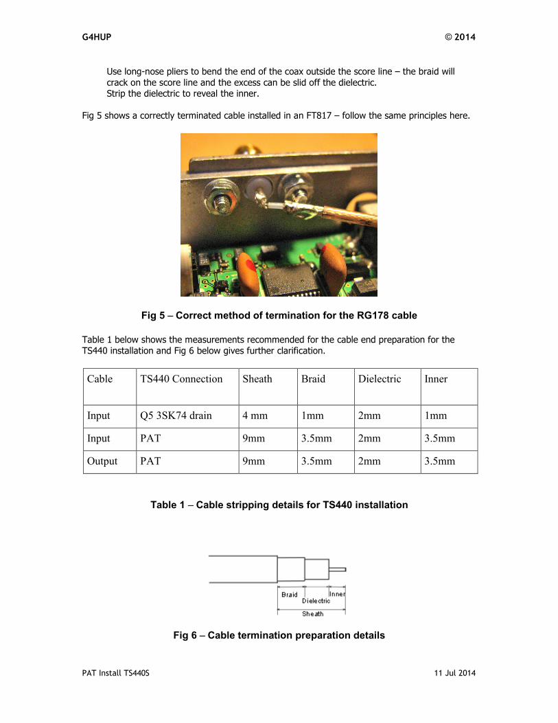
Use long-nose pliers to bend the end of the coax outside the score line – the braid will
crack on the score line and the excess can be slid off the dielectric. Strip the dielectric to reveal the inner.
Fig 5 shows a correctly terminated cable installed in an FT817 – follow the same principles here.
Fig 5 – Correct method of termination for the RG178 cable
Table 1 below shows the measurements recommended for the cable end preparation for the
TS440 installation and Fig 6 below gives further clarification.
Cable TS440 Connection Sheath Braid Dielectric Inner
Input Q5 3SK74 drain 4 mm 1mm 2mm 1mm
Input PAT 9mm 3.5mm 2mm 3.5mm
Output PAT 9mm 3.5mm 2mm 3.5mm
Table 1 – Cable stripping details for TS440 installation
Fig 6 – Cable termination preparation details
G4HUP © 2014
PAT Install TS440S 11 Jul 2014
TS440S Operation with PAT
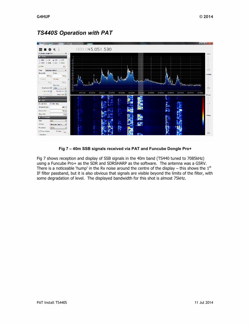
Fig 7 – 40m SSB signals received via PAT and Funcube Dongle Pro+
Fig 7 shows reception and display of SSB signals in the 40m band (TS440 tuned to 7085kHz)
using a Funcube Pro+ as the SDR and SDRSHARP as the software. The antenna was a G5RV. There is a noticeable ‘hump’ in the Rx noise around the centre of the display – this shows the 1st
IF filter passband, but it is also obvious that signals are visible beyond the limits of the filter, with
some degradation of level. The displayed bandwidth for this shot is almost 75kHz.