Embed Size (px)
Citation preview

TS4plus Modular Conveyors for Flexible Manufacturing
Version 3.0
Handle Pallet Payloads up to 250 kg (550 lbs.)

Introduction
TS4plusLinear Motion and Assembly Technologies 8981 500 252 11/07Bosch Rexroth Corp.1-
1
© 2007, Bosch Rexroth CorporationAll rights are held by ROBERT BOSCH GMBH and BOSCH REXROTH CORPORATION, also regarding patent claims. We reserve the right to make technical changes at any time without notice. Errors and omissions excepted.
TS4plus Modular Conveyors
Liability:In no event can the manufacturer accept warranty claims or liability claims for damages resulting from improper use or misuse of the equipment or as a result of changes made to the equipment other than those authorized by the manufacturer. The manufacturer will accept no claim in which non-original spare parts have been used.
0

Bosch Rexroth Corp.Linear Motion and Assembly Technologies
Introduction
TS4plus8981 500 252 11/07 1-
1
2
3
4
5
1 6
7
8
Introduction
Workpiece Pallets
Drive and Return Units
Chain Sections and Leg Sets
Transverse Conveyors
Lift Transfer Modules
Lift Position Modules
Traffi c Control
Quick Reference to Catalog Sections
1
1
9Technical Data
10Part Number Index

Introduction
TS4plusLinear Motion and Assembly Technologies 8981 500 252 11/07Bosch Rexroth Corp.1-
1
Table of Contents
Section 1–Introduction1-4 – 1-7 System overview1-8 Customer support services1-9 Application photos1-10 How to use this catalog
Section 2–Workpiece Pallets2-2 – 2-3 WT4-S Assembled workpiece pallets2-4 – 2-5 WT4-S Workpiece pallet frame kits2-6 – 2-7 WT4-S 12.7mm Aluminum pallet plates2-8 – 2-9 WT4-S 19.1mm Aluminum pallet plates2-10 – 2-11 WT4-S/F Assembled open center pallets
Section 3–Drive and Return Units3-1 UM4S Return units 3-2 – 3-3 AS4S/S Standard drive units 3-4 – 3-5 AS4S/H Heavy-duty drive units
Section 4–Chain Sections 4-1 GT4/R Roller chain4-1 Roller chain disassembly tool4-2 – 4-3 ST4-S/R Roller chain conveyor sections4-4 Connection links4-4 Cross links4-5 ST4-S/R Pallet accelerator kit4-6 – 4-8 Leg Sets4-8 Foundation brackets and anchor bolts
2

Bosch Rexroth Corp.Linear Motion and Assembly Technologies
Introduction
TS4plus8981 500 252 11/07 1-
1
3
Section 5–Transverse Conveyors5-2 – 5-3 BS4-S/R Transverse conveyors5-4 – 5-5 BS4-S/R-H Heavy Duty Transverse conveyors
Section 6–Lift-Transfer Modules6-1 – 6-4 HQ4 Lift-transfer unit
6-5 – 6-8 WI4-S Cushioned transfer stops
6-9 – 6-10 TR4-S Track rollers
Section 7–Lift-Position Modules7-2 – 7-3 PE4 Lift-position unit
Section 8–Traffi c Control8-1 VE4-S/AR Anti-rebound stop8-2 – 8-3 VE4/D100 Cushioned stop gate8-4 – 8-5 VE4/D250 Heavy duty cushioned stop gate8-6 Safety stop kit8-7 – 8-8 Proximity Switches & Bracket8-9 Mini Rocker
Section 9–TS4plus Technical Data9-1 – 9-2 Pallet plate loading9-3 Chain tensioning option9-4 Pneumatic summary9-4 Pneumatic diagrams9-5 Pneumatics from Rexroth9-6 Metric/English conversion charts
Section 10–Index10-0 – 10-1 Part Number Index

Introduction
TS4plusLinear Motion and Assembly Technologies 8981 500 252 11/07Bosch Rexroth Corp.1-
1
TS4plus–Flexible assembly solutions for heavy loads
The TS4plus assembly conveyor, along with TS 1 and TSplus, is part of the new generation of TS modular conveyors for fl exible assembly. Like all TS products, TS4plus is a workpiece-pallet based conveyor system designed to improve manufacturing productivity and product quality while allowing for maximum as-sembly fl exibility.
TS4plus lets you respond quickly to changing assembly requirements
All components of the TS4plus system are pre-engineered and modular. The system can be easily expanded, recon-fi gured, or relocated as your production needs change. You can phase in your investment as time and budget permit. Start with a simple conveyor for basic as-sembly, and grow into a fully automated, progressive assembly system. As production requirements change, TS4plus gives you the fl exibility to add manual or automatic workstations.
The workpiece pallet—heart of the TS4plus system
TS4plus conveyors transport parts and assemblies on workpiece pallets. The workpiece pallets, up to 1243 x 1243 mm (49” x 49”) are not attached to the con-veying medium that transports them. This method offers many benefi ts for product assembly applications.
Positioning. A Rexroth Lift Position Unit can position pallets at workstations with a repeatable accuracy of ±0.125 mm, making precision assembly operations possible.
Tooling. Pallets can be equipped with fi xtures to secure parts and assemblies for manual or automated operations.
Sensing. Conveyor mounted proximity switches work with exciter plates on the pallet corner bumpers to detect pallet presence.
Stopping. Pallets can be stopped on the leading or trailing edge–regardless of pallet orientation on the conveyor. Pallets can also be accumulated in queue and released one at a time.
The workpiece pallet can be accessed from all sides—allowing maximum fl exibility in automated or manual workstation placement around the conveyor.
Durable low-friction roller chain
The workpiece pallets are transported by a durable low-friction roller chain, allowing the accumulation of even heavily loaded pallets.
SECTION 2Assembled Frame Style
Pallets
4
SECTION 2Assembled Work-
piece Pallet

Bosch Rexroth Corp.Linear Motion and Assembly Technologies
Introduction
TS4plus8981 500 252 11/07 1-
1
SECTION 5Transverse Conveyors
SECTION 4Conveyor Sections
and Roller Chain
SECTION 4Leg Sets and Founda-
tion Brackets
SECTION 3Return Units
SECTION 3Drive Units
When planning a system layout it is very important to consider the individual re-quirements of the assembly operation.
Pallet payload and size, cycle time, process fl ow, product changes, pallet fi xturing and fl oor space are a few of the parameters that determine the best confi guration for your assembly system.
TS4plus is widely used in the appliance and automotive industries because of its ability to handle large and heavy products like automotive drivetrain components, ranges or even refrigerators.
5
Planning the System Layout
SECTION 6Lift Transfer Units
and Transfer Stops
SECTION 6Lift Position Unit
SECTION 7Cushioned Stopsand Traffi c Control

Introduction
TS4plusLinear Motion and Assembly Technologies 8981 500 252 11/07Bosch Rexroth Corp.1-
1
Choose the TS4plus confi guration that best suits your application
Numerous confi guration possibilities
With TS4plus, you have the freedom to select the confi guration best suited to your layout and production requirements. Construct and combine four basic con-fi gurations: in-line, parallel, rectangular, and over/under. Space constraints and process complexity are often key factors in deciding which confi guration(s) will work best for your application.
In-line
In-line systems are the simplest con-fi guration and form the basis for all other TS4plus confi gurations.In-line systems can be used for point-to-point transport, or to create spur-lines for inspection or assembly operations. They can also be used to interconnect or extend other TS4plus systems and con-fi gurations. Each in-line system consists of a drive and a return, with the pallets transported along roller chain conveyor
Parallel
Parallel systems are formed by linking two in-line systems, running in opposite directions, together side-by-side, with track rollers bridging the gap between the lines. Lift Transfer Units move the pallets on and off the main line. This allows con-tinuous circulation of pallets, and can be used where the capacity of a rectangular system is not needed, or where space is
Rectangular
Rectangular systems use in-line con-veyors, with Lift Transfer Units at the “corners” to move the pallets on and off the main lines. This layout offers the advantage of continuous pallet circulation without the spacing limitations created by track rollers. In addition, the use of stan-dard conveyor sections for the transverse sections means that there is no loss in load capacity or accumulation capabilities. Process stations can be set up all the way around the conveyor, if needed.
Over/Under
Over/under systems consist of two con-veyor sections mounted one above the other. One conveyor section transports the workpiece pallet through the assem-bly process. The other conveyor section then returns the workpiece pallet to the beginning of the line. The upper and lower sections are connected together by verti-cal transfer units on each end. Over/under confi gurations provide a signifi cant sav-ings in fl oor space requirements, making them ideal for applications where space is at a premium.
These are just some of the possibilities with TS4plus pre-engineered conveyors. No matter what the assembly require-ment, Rexroth modular components make manufacturing truly fl exible.
6

Bosch Rexroth Corp.Linear Motion and Assembly Technologies
Introduction
TS4plus8981 500 252 11/07 1-
1
Applications for TS4plusThe TS4plus system can be used in precision assembly and testing applica-tions with a total pallet payload up to 250 kg (550 lbs). This makes it an excellent solution for the automotive, and appliance industries.
Typical types of products that can be as-sembled using TS4plus include:
• Automotive assemblies• Drivetrain components• Home appliances• Televisions• Electronics
“Cycle-independent stations” can be used to balance assembly operations with differing cycle times.
Fluctuations in production quantity can be easily accommodated by bypassing assembly workstations.
Different products can also be processed simultaneously.
A
A
A
A
A A
A
A
A
Operation 1 Operation 2
A
A
A
A
A
A A A
Station A Station B
B
A
A
AB
B
A
Station A Station B
B BA
Further tailor your system to match specifi c assembly requirementsWith TS4plus assembly conveyors, work-piece pallets can be selectively routed to off-line manual or automated stations. These “cycle-independent stations” allow you to accommodate fl uctuating produc-tion quantities and to balance cycle times between work-stations. This, in turn, permits manual and automated worksta-tions to be combined on the same line.
Cycle-independent stations are con-structed using standardized modules and therefore are easily added to the main conveyor.
7

Introduction
TS4plusLinear Motion and Assembly Technologies 8981 500 252 11/07Bosch Rexroth Corp.1-
1
Every assembly project has its challenges. But you don’t have to meet them alone. Bosch Rexroth offers the most compre-hensive program of customer support available anywhere, from do-it-yourself projects to turnkey installations. Now that you’ve taken the fi rst step by requesting this catalog, we’ll help you with all the rest—from the initial quote and installation, to servicing your line years from now.
Application engineeringfrom experts, or via CADWhatever your application, our application engineers have probably worked on it. They’ll carefully review your requirements — cycle time, payload, fl oor space, pro-cess fl ow — and devise the best conveyor layout to meet them.
If you’d rather design the system yourself, our FMSsoft™ program makes it easy. It not only creates a 3-D layout based on your parameters, but generates a bill of materials to simplify ordering. This user-friendly program works on any CAD system using AutoCAD® Release 2000 or later.
Whichever you prefer, we’ll respond quickly with a detailed quotation and answer any questions you may have. And we’ll work with you directly, or through your local Bosch Rexroth systems integra-tor, to schedule delivery and installation when you need it.
Complete support: before, during and after installation
Systems integrators make Rexroth expertise their businessFor large projects, Bosch Rexroth integra-tors provide total support on a local basis, putting years of expertise with Rexroth products to work for you. They offer com-plete project management of automated assembly systems, including engineering, manufacturing, installation, and debug-ging. We work closely with our network of integrator partners, providing them with the latest in product information, as well as software and service training.
After-sale service assuresyour continued successThe Bosch Rexroth commitment continues long after your system is up and running. Our highly qualifi ed, experienced staff of service experts is always available for maintenance questions, spare parts or-ders, fi eld service, and more. We’re also happy to provide training in the installation or maintenance of any Rexroth products, either in your facility or at our headquar-ters in Buchanan, Michigan.
8

Bosch Rexroth Corp.Linear Motion and Assembly Technologies
Introduction
TS4plus8981 500 252 11/07 1-
1
Application Photos
Of course, you don’t want to call Rexroth every time you have a question. Fortu-nately, our approach to documentation ensures that you won’t have to. Product catalogs (like this one) make planning and ordering easy, with detailed specifi cations and dimensions, 3-D illustrations and part numbers.
In a hurry? The latest news, products, application ideas and more are all just a click away, on the Bosch Rexroth Corporation website. You’ll fi nd your local authorized integrator there, too, at: www.boschrexroth-us.com. Visit today, and see why it pays to specify Rexroth.
When your system arrives, everything you need to know for set-up and operation comes with it. And if you’d like to know which spare parts to keep on hand, we’ll send you an exploded-view spare parts catalog or a customized spare parts list just for your system.
More available on-line
Documentation that answers(and anticipates) your questions
9

Introduction
TS4plusLinear Motion and Assembly Technologies 8981 500 252 11/07Bosch Rexroth Corp.1-
1
This catalog describes every module needed to construct a TS4plus assembly conveyor. The modules are organized in the order you would most likely need to specify your system. The chart below lists some common Bosch terms and their defi nitions that are used in this catalog.
What your order should includeIn order for us to process your order as quickly and accurately as possible, please make sure you specify:
• 10-digit part number • Name of the module • Quantity • Other ordering parameters
as needed
For example, to order 10 assembled workpiece pallets (page 2-2) measur-ing 643 mm square with 12.7 mm pallet plates, your purchase order would include:
Module name: Workpiece PalletQuantity: 10Part number: 8981 021 895Additional info: (None required)
Modules such as drive units, lift transfer units, or positioning modules require you to specify the base 10-digit part number as listed, and then select from a list of options when ordering. These options include such things as voltage/frequency, conveyor speed, motor location, and conveyor width.As you specify your options, a 15-digit part number will be created, unique to
Getting started using this catalog
those options that you have specifi ed. This part number provides customer ser-vice with the exact information they need to build and service your module. Always use this number when ordering parts for your module.
If you need application assistance, or have any questions about ordering, feel free to contact us or your nearest Bosch Rexroth representative.
Rexroth Terms and Defi nitions
B
LWT
LWT
BQ
L
L
B BL
BWT
Line Flow
Lift TransferUnit
TransverseConveyor
WorkpiecePallet
Main Conveyor Section
NominalHeight
T-Slot
ProfileT-Bolt T-Nut
Transport LevelNominal Height:Distance from floor to top of transport media.
Transport Level:
WTBLBWTLWTBQBL
= Workpiece pallet= Nominal width= Nominal length= Workpiece pallet width= Workpiece pallet length= Lift transfer unit width= Lift transfer unit length
T-Slot:The longitudinal slot in the extrudedaluminum profiles of the conveyor
T-Bolt and T-Nut:Hardware used to secure componentsand accessories to the T-slots of a profile
BWT150= Load Carrying capacity in Kg
= Pallet Flow
1-800-322-6724In Canada:
1-905-335-5511
10

Bosch Rexroth Corp.Linear Motion and Assembly Technologies
Workpiece Pallets
TS4plus8981 500 252 11/07 2-
2
Section 2—Workpiece Pallets
WT4-S, WT4-S-HAssembled Workpiece Pallets2-2 to 2-3
The WT4-S workpiece pallet forms the heart of the TS4plus system. The edge-guided pallets are available in a wide range of sizes and with two differ-ent aluminum pallet plate thicknesses to fi t your production needs. They can be ordered fully assembled, or purchased in kits of individual components for on-site assembly, with or without the pallet plate. A very lightweight, open center (frame) style pallet is also available.
WT4-S/FAssembled Open Center Pallets2-10 to 2-11
WT4-S, WT4-S-HAluminum Pallet Plates2-6 to 2-9
WT4-SWorkpiece Pallet Frame Kits2-4 to 2-5
1

Workpiece Pallets
TS4plusLinear Motion and Assembly Technologies 8981 500 252 11/07Bosch Rexroth Corp.2-
2
Leng
th (
L WT)
Width (BWT)
443
643
843
1043
1243
8981 021 905
8981 021 906
8981 021 907
8981 021 908
8981 021 909
•8981 021 910
8981 021 911
8981 021 912
8981 021 913
••
8981 021 914
8981 021 915
8981 021 916
•••
8981 021 917
8981 021 918
••••
8981 021 919
443 643 843 1043 1243
Leng
th (
L WT)
Width (BWT)
443
643
843
1043
1243
8981 021 890
8981 021 891
8981 021 892
8981 021 893
8981 021 894
•8981 021 895
8981 021 896
8981 021 897
8981 021 898
••
8981 021 899
8981 021 900
8981 021 901
•••
8981 021 902
8981 021 903
••••
8981 021 904
443 643 843 1043 1243
Assembled Workpiece Pallets
Fully assembled TS4plus workpiece pallets are available in 15 standard sizes ranging from 443 x 443mm to 1243 x 1243mm.
The workpiece pallets consist of frame modules (corners and extensions) and a support plate. The frame modules are made from electrically conductive UHMW-PE and include horizontal exciter plates to indicate relative positioning when used in conjunction with proximity switches. The frame modules also include integrated bumpers, which dampen the impact of pallet-to-pallet contact. The support plate is made of aluminum (12.7mm or 19.1mm thick).
Ordering Information for Assembled Workpiece Pallets WT4-S with 12.7 mm pallet plates
Ordering Information for Assembled Workpiece Pallets WT4-S-H with 19.1 mm pallet plates
Assembled workpiece pallets also have four pressed-in hardened steel position-ing bushings which provide precise loca-tion of the workpiece pallet for automated assembly operations when used with Rexroth positioning modules. M8x25 screws (quantities vary according to pallet size) are used to secure the frame modules to the support plates.
Model WT4-S, WT4-S-H
2
Workpiece Pallet Payloads (in kg)
* Maximum load is the combined weight of all pallet components, fi xture, and parts. Please refer to Section 8 for application notes on pallet payloads as they relate to load application points.
Workpiece Palletload-bearing edgeLWT or BWT in mm
44364384310431243
MaximumLoad in kg*
85125165210250

Bosch Rexroth Corp.Linear Motion and Assembly Technologies
Workpiece Pallets
TS4plus8981 500 252 11/07 2-
2
3
NOTE: Dimensions are for reference only. Contact Rexroth for a detailed machining drawing.
WT4-S Workpiece Pallet Weights (in kg) WT4-S-H Workpiece Pallet Weights (in kg)
11.8
16.9
22.0
27.0
32.2
24.0
31.2
38.3
45.4
40.4
49.5
58.8
60.8
72.0 85.4
19.1 mm fixtureplates
Leng
th (
L WT)
Width (BWT)
443
643
843
1043
1243
8.6
12.1
15.7
19.2
22.8
17.0
22.0
26.9
31.8
28.3
34.6
40.9
42.2
50.0 59.0
443
weight
643 843 1043 1243
weight weight weight weight
12.7 mm fixtureplates
Leng
th (
L WT)
Width (BWT)
443
643
843
1043
1243
443
weight
643 843 1043 1243
weight weight weight weight
• • • •
• • •
• •
•
• • • •
• • •
• •
•
BWT
443
443
443
443
443
643
643
643
643
843
843
843
1043
1043
1243
LWT
443
643
843
1043
1243
643
843
1043
1243
843
1043
1243
1043
1243
1243
A
81.5
181.5
281.5
381.5
481.5
181.5
281.5
381.5
481.5
281.5
381.5
481.5
381.5
481.5
481.5
B
161.5
261.5
361.5
461.5
561.5
261.5
361.5
461.5
561.5
361.5
461.5
561.5
461.5
561.5
561.5
C
221.5
321.5
421.5
521.5
621.5
321.5
421.5
521.5
621.5
421.5
521.5
621.5
521.5
621.5
621.5
D
81.5
81.5
81.5
81.5
81.5
181.5
181.5
181.5
181.5
281.5
281.5
281.5
381.5
381.5
481.5
E
161.5
161.5
161.5
161.5
161.5
261.5
261.5
261.5
261.5
361.5
361.5
361.5
461.5
461.5
561.5
F
221.5
221.5
221.5
221.5
221.5
321.5
321.5
321.5
321.5
421.5
421.5
421.5
521.5
521.5
621.5
Dimensional Data for WT4-S, WT4-S-H
12
39.05 for 19.1mm plate32.70 for 12.7mm plate
D80 D60
60E F
AA
8060
60B
C
80
BWT +12
BWT –1.2
L WT
+12
L WT
–1.2
B
L
0.1
0.1

Workpiece Pallets
TS4plusLinear Motion and Assembly Technologies 8981 500 252 11/07Bosch Rexroth Corp.2-
2
Workpiece Pallet Frame Kits
Workpiece pallet frames can also be purchased as kits for on-site assembly. Ordering pallet frame kits make it possible to perform any machining necessary to the pallet plate for fi xturing prior to assem-bling the pallet. 12.7mm thick aluminum pallet plates are available separately on page 2-6 to 2-7. See page 2-8 to 2-9 for 19.1mm thick aluminum pallet plates
In cases where substantial fi xture tool-ing is being used, it may be possible to eliminate the pallet plate entirely, as well as the cost and weight associated with it.
Each workpiece pallet frame kit includes frame extension modules, corner modules, four positioning knurled bushings, and M8x25 screws that are used to secure a pallet plate (12.7mm or 19.1mm) to the frame extensions and corners.
Leng
th (L
WT)
Width (BWT)
443
643
843
1043
1243
8981 021 920
8981 021 921
8981 021 922
8981 021 923
8981 021 924
•8981 021 925
8981 021 926
8981 021 927
8981 021 928
••
8981 021 929
8981 021 930
8981 021 931
•••
8981 021 932
8981 021 933
••••
8981 021 934
443 643 843 1043 1243
NOTE: Pallet frame kits DO NOT include pallet plates.
WT4-S
Ordering Information for Workpiece Pallet Frame Kits
4
Corner
Positioning Bushing
Extension
Knurled Bushing
M8 x 25 Screw

Bosch Rexroth Corp.Linear Motion and Assembly Technologies
Workpiece Pallets
TS4plus8981 500 252 11/07 2-
2
5
BWT
443
443
443
443
443
643
643
643
643
843
843
843
1043
1043
1243
LWT
443
643
843
1043
1243
643
843
1043
1243
843
1043
1243
1043
1243
1243
A
81.5
181.5
281.5
381.5
481.5
181.5
281.5
381.5
481.5
281.5
381.5
481.5
381.5
481.5
481.5
B
161.5
261.5
361.5
461.5
561.5
261.5
361.5
461.5
561.5
361.5
461.5
561.5
461.5
561.5
561.5
C
221.5
321.5
421.5
521.5
621.5
321.5
421.5
521.5
621.5
421.5
521.5
621.5
521.5
621.5
621.5
D
81.5
81.5
81.5
81.5
81.5
181.5
181.5
181.5
181.5
281.5
281.5
281.5
381.5
381.5
481.5
E
161.5
161.5
161.5
161.5
161.5
261.5
261.5
261.5
261.5
361.5
361.5
361.5
461.5
461.5
561.5
F
221.5
221.5
221.5
221.5
221.5
321.5
321.5
321.5
321.5
421.5
421.5
421.5
521.5
521.5
621.5
Dimensional Data for Pallet Frames
NOTE: Dimensions are for reference only. Contact Rexroth for a detailed machining drawing.
12
39.05 for 19.1mm plate32.70 for 12.7mm plate
D80 D60
60E F
AA
8060
60B
C
80
BWT +12
BWT –1.2
L WT
+12
L WT
–1.2
34
18 30.5
24
ø16
Positioning
Bushing
Workpiece Pallets
TS4plusLinear Motion and Assembly Technologies 8981 500 252 11/07Bosch Rexroth Corp.2-
2
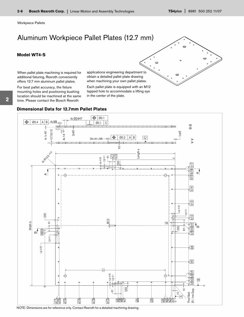
When pallet plate machining is required for additional fi xturing, Rexroth conveniently offers 12.7 mm aluminum pallet plates.
For best pallet accuracy, the fi xture mounting holes and positioning bushing location should be machined at the same time. Please contact the Bosch Rexroth
Aluminum Workpiece Pallet Plates (12.7 mm)
Model WT4-S
6
A-A
B-B
12.7
±0.1
5
Ø0.1 Ø0.4 A B Ø0.1 C
4x Ø24H74x M8
4x 1
x 45˚
2x45
˚
4x 1
4 +0.0
–.05
1x45
˚
C Ø0.2 A B26x-40 x M8
a4
b7b1
2b1
5
a1a3 a2
b16
Wid
th b
Leng
th a
4x R10
.5 +0.2
(20)
(20)
(20)
b6b1
4b1
3
b9b8
M12
Proo
f Mark
Ø1; 1
mm D
eep
b17
b5b4
b3b2
a5a6a9 a8 a7a13
a12
a14
a17
a16
a15
(20)
B
A AB
6114
–0.0
513
–0.1
14–0
.05
61
61
8.5
0a11
a10
0
13–0
.1
14–0
.05
13–0
.1
14–0
.05
13–0
.161 b1
0b1
1
0
0
10
B
d
10A
b1
c
Dimensional Data for 12.7mm Pallet Plates
NOTE: Dimensions are for reference only. Contact Rexroth for a detailed machining drawing.
applications engineering department to obtain a detailed pallet plate drawing when machining your own pallet plates.
Each pallet plate is equipped with an M12 tapped hole to accommodate a lifting eye in the center of the plate.
Bosch Rexroth Corp.Linear Motion and Assembly Technologies
Workpiece Pallets
TS4plus8981 500 252 11/07 2-
2
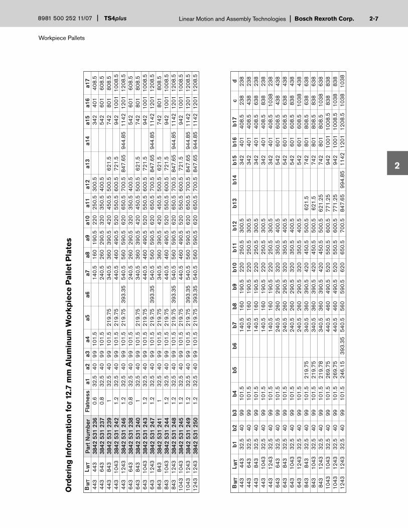
Ord
erin
g In
form
atio
n f
or
12.7
mm
Alu
min
um
Wo
rkp
iece
Pal
let
Pla
tes
7
BW
TL W
T
BW
TL W
T
Par
t Num
ber
Flat
ness
a1a2
a3a4
a5a6
a7a8
a9a1
0a1
1a1
2a1
3a1
4a1
5a1
6a1
744
344
30.
632
.54
09
910
1.5
140.
516
019
0.5
220
250.
530
0.5
342
401
408.
544
364
30.
832
.54
09
910
1.5
240.
526
029
0.5
320
350.
540
0.5
542
601
608.
544
384
31
32.5
40
99
101.
521
9.75
340.
536
039
0.5
420
450.
550
0.5
621.
574
280
180
8.5
443
1043
1.2
32.5
40
99
101.
521
9.75
440.
546
049
0.5
520
550.
560
0.5
721.
594
210
0110
08.5
443
1243
1.2
32.5
40
99
101.
521
9.75
393.
3554
0.5
560
590.
562
065
0.5
700.
584
7.65
944.
8511
4212
0112
08.5
643
643
0.8
32.5
40
99
101.
524
0.5
260
290.
532
035
0.5
400.
554
260
160
8.5
643
843
132
.54
09
910
1.5
219.
7534
0.5
360
390.
542
045
0.5
500.
562
1.5
742
801
808.
564
310
431.
232
.54
09
910
1.5
219.
7544
0.5
460
490.
552
055
0.5
600.
572
1.5
942
1001
1008
.564
312
431.
232
.54
09
910
1.5
219.
7539
3.35
540.
556
059
0.5
620
650.
570
0.5
847.
6594
4.85
1142
1201
1208
.584
384
31
32.5
40
99
101.
521
9.75
340.
536
039
0.5
420
450.
550
0.5
621.
574
280
180
8.5
843
1043
1.2
32.5
40
99
101.
521
9.75
440.
546
049
0.5
520
550.
560
0.5
721.
594
210
0110
08.5
843
1243
1.2
32.5
40
99
101.
521
9.75
393.
3554
0.5
560
590.
562
065
0.5
700.
584
7.65
944.
8511
4212
0112
08.5
1043
1043
1.2
32.5
40
99
101.
521
9.75
440.
546
049
0.5
520
550.
560
0.5
721.
594
210
0110
08.5
1043
1243
1.2
32.5
40
99
101.
521
9.75
393.
3554
0.5
560
590.
562
065
0.5
700.
584
7.65
944.
8511
4212
0112
08.5
1243
1243
1.2
32.5
40
99
101.
521
9.75
393.
3554
0.5
560
590.
562
065
0.5
700.
584
7.65
944.
8511
4212
0112
08.5
b1b2
b3b4
b5b6
b7b8
b9b1
0b1
1b1
2b1
3b1
4b1
5b1
6b1
7c
d44
344
332
.540
9910
1.5
140.
516
019
0.5
220
250.
530
0.5
342
401
408.
523
823
844
364
332
.540
9910
1.5
140.
516
019
0.5
220
250.
530
0.5
342
401
408.
543
823
844
384
332
.540
9910
1.5
140.
516
019
0.5
220
250.
530
0.5
342
401
408.
563
823
844
310
4332
.540
9910
1.5
140.
516
019
0.5
220
250.
530
0.5
342
401
408.
583
823
844
312
4332
.540
9910
1.5
140.
516
019
0.5
220
250.
530
0.5
342
401
408.
510
3823
864
364
332
.540
9910
1.5
240.
526
029
0.5
320
350.
540
0.5
542
601
608.
543
843
864
384
332
.540
9910
1.5
240.
526
029
0.5
320
350.
540
0.5
542
601
608.
563
843
864
310
4332
.540
9910
1.5
240.
526
029
0.5
320
350.
540
0.5
542
601
608.
583
843
864
312
4332
.540
9910
1.5
240.
526
029
0.5
320
350.
540
0.5
542
601
608.
510
3843
884
384
332
.540
9910
1.5
219.
7534
0.5
360
390.
542
045
0.5
500.
562
1.5
742
801
808.
563
863
884
310
4332
.540
9910
1.5
219.
7534
0.5
360
390.
542
045
0.5
500.
562
1.5
742
801
808.
583
863
884
312
4332
.540
9910
1.5
219.
7834
0.5
360
390.
542
045
0.5
500.
562
1.25
742
801
808.
510
3863
810
4310
4332
.540
9910
1.5
269.
7544
0.5
460
490.
552
055
0.5
600.
577
1.25
942
1001
1008
.583
883
810
4312
4332
.540
9910
1.5
269.
7544
0.5
460
490.
552
055
0.5
600.
577
1.25
942
1001
1008
.510
3883
812
4312
4332
.540
9910
1.5
246.
1539
3.35
540.
556
059
0.5
620
650.
570
0.5
847.
6599
4.85
1142
1201
1208
.510
3810
38
3842
531
236
3842
531
237
3842
531
239
3842
531
242
3842
531
246
3842
531
238
3842
531
240
3842
531
243
3842
531
247
3842
531
241
3842
531
244
3842
531
248
3842
531
245
3842
531
249
3842
531
250

Workpiece Pallets
TS4plusLinear Motion and Assembly Technologies 8981 500 252 11/07Bosch Rexroth Corp.2-
2
Heavy Duty Aluminum Pallet Plates (19.1 mm)
Model WT4-S-H
8
When pallet plate machining is required for additional fi xturing, Rexroth conveniently offers 19.1mm aluminum pallet plates.
For best pallet accuracy, the fi xture mounting holes and positioning bushing location should be machined at the same time. Please contact the Bosch Rexroth
A-A
B-B
a4
b7b1
2b1
5
a1a3 a2
b16
Wid
th b
Leng
th a
4x R10
.5 +0.2
(20)
(20)
b6b1
4b1
3
b9b8
4x 1
x 45˚
M12
Proo
f Mark
Ø1; 1
mm D
eep
b17
b5b4
b3b2
a5a6a9 a8 a7a13
a12
a14
a17
a16
a15
(20)
B
A AB
6114
–0.0
513
–0.1
14–0
.05
61
61 0a11
a10
0
13–0
.1
14–0
.05
13–0
.1
14–0
.05
13–0
.161 b1
0b1
1
0
0
10
B
d
10A
b1
C Ø0.2 A B
Ø0.1 Ø0.4 A B Ø0.1 C
1x45
˚
19.0
5±0.
15
26x-40 x M8
4x Ø24H7
2x45
˚
4x M8
8.5
4x 1
4 +0.0
–.05
c
(20)
Dimensional Data for 19.1mm Pallet Plates
NOTE: Dimensions are for reference only. Contact Rexroth for a detailed machining drawing.
applications engineering department to obtain a detailed pallet plate drawing when machining your own pallet plates.
Each pallet plate is equipped with an M12 tapped hole to accommodate a lifting eye in the center of the plate.

Bosch Rexroth Corp.Linear Motion and Assembly Technologies
Workpiece Pallets
TS4plus8981 500 252 11/07 2-
2
9
Ord
erin
g In
form
atio
n f
or
19.1
mm
Alu
min
um
Wo
rkp
iece
Pal
let
Pla
tes
BW
TL W
T
BW
TL W
T
Par
t Num
ber
Flat
ness
a1a2
a3a4
a5a6
a7a8
a9a1
0a1
1a1
2a1
3a1
4a1
5a1
6a1
744
344
30.
632
.54
09
910
1.5
140.
516
019
0.5
220
250.
530
0.5
342
401
408.
544
364
30.
832
.54
09
910
1.5
240.
526
029
0.5
320
350.
540
0.5
542
601
608.
544
384
31
32.5
40
99
101.
521
9.75
340.
536
039
0.5
420
450.
550
0.5
621.
574
280
180
8.5
443
1043
1.2
32.5
40
99
101.
521
9.75
440.
546
049
0.5
520
550.
560
0.5
721.
594
210
0110
08.5
443
1243
1.2
32.5
40
99
101.
521
9.75
393.
3554
0.5
560
590.
562
065
0.5
700.
584
7.65
944.
8511
4212
0112
08.5
643
643
0.8
32.5
40
99
101.
524
0.5
260
290.
532
035
0.5
400.
554
260
160
8.5
643
843
132
.54
09
910
1.5
219.
7534
0.5
360
390.
542
045
0.5
500.
562
1.5
742
801
808.
564
310
431.
232
.54
09
910
1.5
219.
7544
0.5
460
490.
552
055
0.5
600.
572
1.5
942
1001
1008
.564
312
431.
232
.54
09
910
1.5
219.
7539
3.35
540.
556
059
0.5
620
650.
570
0.5
847.
6594
4.85
1142
1201
1208
.584
384
31
32.5
40
99
101.
521
9.75
340.
536
039
0.5
420
450.
550
0.5
621.
574
280
180
8.5
843
1043
1.2
32.5
40
99
101.
521
9.75
440.
546
049
0.5
520
550.
560
0.5
721.
594
210
0110
08.5
843
1243
1.2
32.5
40
99
101.
521
9.75
393.
3554
0.5
560
590.
562
065
0.5
700.
584
7.65
944.
8511
4212
0112
08.5
1043
1043
1.2
32.5
40
99
101.
521
9.75
440.
546
049
0.5
520
550.
560
0.5
721.
594
210
0110
08.5
1043
1243
1.2
32.5
40
99
101.
521
9.75
393.
3554
0.5
560
590.
562
065
0.5
700.
584
7.65
944.
8511
4212
0112
08.5
1243
1243
1.2
32.5
40
99
101.
521
9.75
393.
3554
0.5
560
590.
562
065
0.5
700.
584
7.65
944.
8511
4212
0112
08.5
b1b2
b3b4
b5b6
b7b8
b9b1
0b1
1b1
2b1
3b1
4b1
5b1
6b1
7c
d44
344
332
.540
9910
1.5
140.
516
019
0.5
220
250.
530
0.5
342
401
408.
523
823
844
364
332
.540
9910
1.5
140.
516
019
0.5
220
250.
530
0.5
342
401
408.
543
823
844
384
332
.540
9910
1.5
140.
516
019
0.5
220
250.
530
0.5
342
401
408.
563
823
844
310
4332
.540
9910
1.5
140.
516
019
0.5
220
250.
530
0.5
342
401
408.
583
823
844
312
4332
.540
9910
1.5
140.
516
019
0.5
220
250.
530
0.5
342
401
408.
510
3823
864
364
332
.540
9910
1.5
240.
526
029
0.5
320
350.
540
0.5
542
601
608.
543
843
864
384
332
.540
9910
1.5
240.
526
029
0.5
320
350.
540
0.5
542
601
608.
563
843
864
310
4332
.540
9910
1.5
240.
526
029
0.5
320
350.
540
0.5
542
601
608.
583
843
864
312
4332
.540
9910
1.5
240.
526
029
0.5
320
350.
540
0.5
542
601
608.
510
3843
884
384
332
.540
9910
1.5
219.
7534
0.5
360
390.
542
045
0.5
500.
562
1.5
742
801
808.
563
863
884
310
4332
.540
9910
1.5
219.
7534
0.5
360
390.
542
045
0.5
500.
562
1.5
742
801
808.
583
863
884
312
4332
.540
9910
1.5
219.
7834
0.5
360
390.
542
045
0.5
500.
562
1.25
742
801
808.
510
3863
810
4310
4332
.540
9910
1.5
269.
7544
0.5
460
490.
552
055
0.5
600.
577
1.25
942
1001
1008
.583
883
810
4312
4332
.540
9910
1.5
269.
7544
0.5
460
490.
552
055
0.5
600.
577
1.25
942
1001
1008
.510
3883
812
4312
4332
.540
9910
1.5
246.
1539
3.35
540.
556
059
0.5
620
650.
570
0.5
847.
6599
4.85
1142
1201
1208
.510
3810
38
3842
531
251
3842
531
252
3842
531
254
3842
531
257
3842
531
261
3842
531
253
3842
531
255
3842
531
258
3842
531
262
3842
531
256
3842
531
259
3842
531
263
3842
531
260
3842
531
264
3842
531
265

Workpiece Pallets
TS4plusLinear Motion and Assembly Technologies 8981 500 252 11/07Bosch Rexroth Corp.2-
2
Leng
th (
L WT)
Width (BWT)
443
643
843
1043
1243
8981 021 935
8981 021 936
8981 021 937
8981 021 938
8981 021 939
•8981 021 940
8981 021 941
8981 021 942
8981 021 943
••
8981 021 944
8981 021 945
8981 021 946
•••
8981 021 947
8981 021 948
••••
8981 021 949
3842 530 529
Description Part Number
443 643 843 1043 1243
Leng
th (
L WT)
Width (BWT)
443
643
843
1043
1243
8.3
10.6
12.8
15.1
17.4
•12.8
15.1
17.4
19.7
••
17.4
19.7
22.0
•••
22.0
24.3
••••
26.6
443 643 843 1043 1243
Positioning Bushing Kit(Qty. 2)
Ordering Information for Assembled Frame Style Pallets WT4-S/F
An alternative to the assembled work-piece pallet is the assembled open center pallet. This pallet includes an aluminum profi le frame, frame extension modules, corner modules and end caps.
The open center pallet is very lightweight in design and allows a greater portion of total pallet payload (pallet, fi xture and product) to be applied to the fi xturing and product.
NOTE: 4 positioning bushings increase the total pallet weight by 2.6 kg.
Assembled Open Center Pallets
NOTE: Positioning bushings are not included and are only required when the pallet is used in conjunction with a lift position unit. Four positioning bushings are required per pallet and they are sold in kits of two.
Assembled Frame Style Weights (in kg)
Model WT4-S/F
The aluminum profi le frame includes a 10mm T-slot, which allows for simple fastening of product supports or fi xturing.
The wear strips are made of UHMW-PE and include an integrated dampening element to absorb the shock when two pallets come into contact with each other.
10
Ordering Information-Positioning Bushings
NOTE: 4 bushings are required per pallet. Order 2 kits per pallet.

Bosch Rexroth Corp.Linear Motion and Assembly Technologies
Workpiece Pallets
TS4plus8981 500 252 11/07 2-
2
Dimensional Data for WT4-S/F
11
L WT-
205
L WT-
160
L WT–
1.2
L WT+
12
L WT-
115
L WT-
53.5
BWT-53.5
BWT-115
BWT+12
BWT–1.2
BWT-205
BWT-16062
7.5
80A
60D
B
C627.5
80GE
60 HF
17
±0.4
±0.
4
Bwt
443
443
443
443
443
643
643
643
643
843
843
843
1043
1043
1243
Lwt
443
643
843
1043
1243
643
843
1043
1243
843
1043
1243
1043
1243
1243
A
81.5
181.5
281.5
381.5
481.5
181.5
281.5
381.5
481.5
281.5
381.5
481.5
381.5
481.5
481.5
B
161.5
261.5
361.5
461.5
561.5
261.5
361.5
461.5
561.5
361.5
461.5
561.5
461.5
561.5
561.5
C
141.5
241.5
341.5
441.5
541.5
241.5
341.5
441.5
541.5
341.5
441.5
541.5
441.5
541.5
541.5
D
221.5
321.5
421.5
521.5
621.5
321.5
421.5
521.5
621.5
421.5
521.5
621.5
521.5
621.5
621.5
E
81.5
81.5
81.5
81.5
81.5
181.5
181.5
181.5
181.5
281.5
281.5
281.5
381.5
381.5
481.5
F
161.5
161.5
161.5
161.5
161.5
261.5
261.5
261.5
261.5
361.5
361.5
361.5
461.5
461.5
561.5
G
141.5
141.5
141.5
141.5
141.5
241.5
241.5
241.5
241.5
341.5
341.5
341.5
441.5
441.5
541.5
H
221.5
221.5
221.5
221.5
221.5
321.5
321.5
321.5
321.5
421.5
421.5
421.5
521.5
521.5
621.5
NOTE: Dimensions are for reference only. Contact Rexroth for a detailed machining drawing.

Drive and Return Units
TS4plusLinear Motion and Assembly Technologies 8981 500 252 11/07Bosch Rexroth Corp.3-
3
Section 3—Drive and Return Units
AS4S/SStandard Drive Unit 3-2 to 3-3
TS4plus drive units power the roller chain along the conveyor sections and help maintain proper chain tension. The return units route the roller chain back through the return channel of the chain profi le. Drives and returns can also be linked together end-to-end to create extended conveyor lines of almost any length without loss of capacity.
AS4S/HHeavy-Duty Drive Unit 3-4 to 3-5
UM4SReturn Unit 3-1
Two types of drive units are available, depending on load requirements for the system.
Different motor electrical options, motor mounting positions, chain tensioners, and transport speeds allow you to confi gure the drive to suit your needs.
1500 2400
0

Bosch Rexroth Corp.Linear Motion and Assembly Technologies
Drive and Return Units
TS4plus842 500 252 10/04 3-Bosch Rexroth Corp.Linear Motion and Assembly TechnologiesTS4plus842 500 252 10/04 3-Bosch Rexroth Corp.Linear Motion and Assembly TechnologiesTS4plus8981 500 252 11/07 3-
3
Return Unit UM4S
The TS4plus return unit routes the roller chain from the transport level to the return channel inside the chain section profi le, where it is fed back to the drive module. Return units are available in standard widths to match the drive module, and can be used with either standard or heavy-duty drives.
Ordering Information for Return Unit UM4S
Width in mm (BWT) Part Number 443 8981 019 495 643 8981 019 496 843 8981 019 497 1043 8981 019 498 1243 8981 019 499
Dimensional Data for UM4S
340280
Bwt+43Bwt+17
Bwt+2Bwt–115
66 TYPTRAN S P O RT
LEVE L
260
1

Drive and Return Units
TS4plusLinear Motion and Assembly Technologies 8981 500 252 11/07Bosch Rexroth Corp.3-
3
AS4S/S Standard Drive Unit 8981 999 219
Your selection:
Your choices are:
In addition to part number, please specify:
__________mm
______V ____Hz
________m/min.
See Table 3-1
12, 15
Drive Unit width (B)
Motor voltage/frequency†
Nominal speed*
______________
______________
L, M, RMotor Position
0˚, 90˚, 270˚Motor Orientation
______________S= SpringF= Fixed**Tensioner Type
443, 643, 843,1043, 1243
Standard Drive Unit
The TS4plus standard drive module is used to pull the roller chain along the chain section at a constant speed. Drives are available with the motor/gearbox mounted between the conveyor rails (mid-mount) or outside the rails on the left or right side. Standard speed and voltage combinations are listed in Table 3-1.
Each drive module includes a chain tensioner. Normally, a spring tensioner with 80 mm of travel is used to provide automatic tensioning of the chain during operation. However, fi xed tensioners are also available for conveyors under 4000 mm in length and reversing applications. Chain tensioners include a bracket which can be used to mount a 12 mm proximity switch (ordered separately) to sense the end of tensioner travel.
Standard drives are rated for a maximum total payload of 1,500 kg per drive. For heavier loads, a heavy-duty drive module is available (page 3-4), or shorter con-veyor sections with additional drive and return modules can be added. Hardware for connecting drive and return modules end-to-end is included.
Ordering Information for Standard Drive Unit AS4S/S
1500
AS4S/S
270˚
90˚
0˚
PalletFlow
PalletFlow
R
M
L
2
Motor Position Motor Orientation
*Full load conveyor speeds vary depending on motor frequency. See Table 3-1**Fixed tensioner required for reverse operation †To omit motor, specify 000V 00Hz

Bosch Rexroth Corp.Linear Motion and Assembly Technologies
Drive and Return Units
TS4plus842 500 252 10/04 3-Bosch Rexroth Corp.Linear Motion and Assembly TechnologiesTS4plus842 500 252 10/04 3-Bosch Rexroth Corp.Linear Motion and Assembly TechnologiesTS4plus8981 500 252 11/07 3-
3
12
174
BWT + 2BWT + 17
BWT + 17
BWT+ 43
BWT+ 2
6698
174
OUTBOARD MOTORMOUNT OPTION
INBOARD MOTOR MOUNT OPTION
13
260
TRANSPORT LEVEL
DIRECTION OF TRAVEL
DIRECTION OF TRAVEL
404
280 285
Technical data for AS4S/S
Nominal conveyor speed = See Table 3-1 Permissible loading weight = 1500 kg Maximum conveyor unit length = 20 m (65 ft.) Motor RPM at 50 Hz = 1400 Motor RPM at 60 Hz = 1700 Motor, electrical specifi cations = See Table 3-1
Electrical data for AS4S/S
Table 3-1Note: Electrical Data for reference only. Refer to motor data plate for actual ratings.
Nom.M/min
1215
HP0.500.50
208/601.81.8
240/601.91.9
380/500.780.78
415/500.720.72
480/600.840.84
575/600.710.71
Full Load Amps @
50 Hz9.812.8
60 Hz11.915.6
Actual Speed
Max. Load = 1500.0 kg
Max. Length F
F
F
= 20 meters
Dimensional data for AS4S/S
3

Drive and Return Units
TS4plusLinear Motion and Assembly Technologies 8981 500 252 11/07Bosch Rexroth Corp.3-
3
Heavy-Duty Drive Unit
The TS4plus heavy-duty drive module is used to pull the roller chain along the chain section at a constant speed. Drives are available with the motor/gearbox mounted between the conveyor rails (mid-mount) or outside the rails on the left or right side. Standard speed and voltage combinations are listed in Table 3-2.
Each drive module includes a chain tensioner. Normally, a spring tensioner with 80 mm of travel is used to provide automatic tensioning of the chain during operation. However, fi xed tensioners are also available for conveyors under 4000 mm in length and reversing applications.
Chain tensioners include a bracket which can be used to mount a 12 mm proximity switch (ordered separately) to sense the end of tensioner travel.
Heavy-duty drives are rated for a maximum total payload of 2,400 kg per drive. For heavier loads, shorter conveyor sections with additional drive and return modules can be added. Hardware for connecting drive and return modules end-to-end is included.
Ordering Information for Heavy-Duty Drive Unit AS4S/H
2400
AS4S/H
270˚
90˚
0˚
PalletFlow
PalletFlow
R
M
L
4
AS4S/H Heavy Duty Drive Unit 8981 999 197
Your selection:
Your choices are:
In addition to part number, please specify:
__________mm
______V ____Hz
________m/min.
See Table 3-2
6, 9,12,15, 18
Drive Unit width (B)
Motor voltage/frequency†
Nominal speed*
______________
______________
______________
L, M, R
Flange Mounting‡
Motor Position
0˚, 90˚, 270˚Motor Orientation
______________S= SpringF= Fixed**
I= IEC 105/IEC120N= NEMA 56C
Tensioner Type
443, 643, 843,1043, 1243
Motor Position Motor Orientation
*Full load conveyor speeds vary depending on motor frequency. See Table 3-2**Fixed tensioner required for reverse operation †To omit motor, specify 000V 00Hz ‡Required for no motor option

Bosch Rexroth Corp.Linear Motion and Assembly Technologies
Drive and Return Units
TS4plus842 500 252 10/04 3-Bosch Rexroth Corp.Linear Motion and Assembly TechnologiesTS4plus842 500 252 10/04 3-Bosch Rexroth Corp.Linear Motion and Assembly TechnologiesTS4plus8981 500 252 11/07 3-
3
OUTBOARD MOTORMOUNT OPTION
INBOARD MOTOR MOUNT OPTION
191
260
280 285
TRANSPORT LEVEL
DIRECTION OF TRAVEL
DIRECTION OF TRAVEL
472
66
121191
12
BWT + 2BWT + 17
BWT+ 17
BWT+ 43
BWT+ 2
13
Dimensional Data for AS4S/H
Nom.M/min
69
121518
HP0.50.5
0.750.750.75
208/601.81.82.92.92.9
240/601.91.92.92.92.9
380/500.780.781.61.61.6
415/500.720.721.61.61.6
480/600.840.841.61.61.6
575/600.710.711.11.11.1
Full Load Amps @
50 Hz6.88.5
10.612.517.7
60 Hz8.3
10.412.915.218.8
Actual Speed
5
Technical data for AS4S/H
Nominal conveyor speed = See Table 3-2 Permissible loading weight = 2400 kg Maximum conveyor unit length = 20 m (65 ft.) Motor RPM at 50 Hz = 1400 Motor RPM at 60 Hz = 1700 Motor, electrical specifi cations = See Table 3-2
Electrical data for AS4S/H
Max. Load = 2400.0 kg
Max. Length F
F
F
= 20 meters
Table 3-2Note: Electrical Data for reference only. Refer to motor data plate for actual ratings.

Chain Sections and Leg Sets
TS4plusLinear Motion and Assembly Technologies 8981 500 252 11/07Bosch Rexroth Corp.4-
4
Section 4—Chain Sections and Leg Sets
ST4-S/RChain Conveyor Sections 4-2 to 4-3
A key factor in the fl exibility of the TS4plus system is the modular, T-slotted design of the conveyor sections, leg sets, and cross links.
By using aluminum conveyor section profi les, it is possible to build a system to meet whatever length requirements you may have. In addition, the profi les
GT4/RRoller Chain 4-1
Cross Links4-4
Roller Chain Disassembly Tool4-1
Connection Links4-4
SZ4S/ESingle Leg Sets 4-6
SZ4S/DDrive/Return Leg Sets4-6
SZ4S/TParallel Leg Sets4-7
SZ4S/UOver/Under Leg Sets4-7
have 10mm T-slots that provide a mount-ing location for stops, control systems, proximity sensors, and other conveyor modules, as well as a wide variety of other components and accessories.
The roller chain provides a low friction transport medium with the ability to handle heavy loads and pallet accumulation.
0
Foundation Brackets4-8
ST4/RPallet Accelerator Kit 4-5
SZ2BS4 Leg Sets 4-8
SZ2/HBS4 Heavy Duty Leg Sets 4-8

Bosch Rexroth Corp.Linear Motion and Assembly Technologies
Chain Sections and Leg Sets
TS4plus8981 500 252 11/07 4-
4
Roller Chain
The TS4plus roller chain provides a low friction transport medium with the ability to handle heavy loads and pallet accumulation.
Roller chain is available in 5 meter rolls; each 5 meter roll includes one master link. The chain is installed by connecting one roll to the next with master links until one side of the conveyor is complete. Any remaining chain can then be used for installation on the other side of the conveyor. Additional master links can be ordered as needed.
To calculate the length of chain needed per side, use the formula in the box at right. When ordering chain, always round up to the next complete 5 meter roll.
The chain will stretch over a period of time. Chain tensioners in the drive units compen-sate for this stretch. When the tensioner is extended to its maximum stroke, the chain must be serviced and the tensioner reset.
Ordering Information for Roller Chain GT4/R
Roller chain required per side:
D + R + (2 x L)
R
L
D
L = conveyor section length
R = chain in return unit = 609 mm
D = chain in drive unit = 1090 mm
Function of the power-and-free conveyor chain
Transport-carrieraccumulationzone
Transport carrierStop gate
Direction of rotationof conveyor rollers
19.05 (3/4")
43
26
Roller Chain Disassembly Tool
This tool is used to simplify disassembly of the roller chain by pushing out the link pins, and can be used on any segment. Recon-necting the chain after removal of unneces-sary links requires the use of a master link (see the “Roller Chain” section above).
Ordering Information for Roller Chain Disassembly Tool
GT4/R
Part Number Roller Chain, 5 meter roll 8981 021 173 Master Link 8981 021 175
Part Number Roller Chain disassembly tool 8981 020 124
1

Chain Sections and Leg Sets
TS4plusLinear Motion and Assembly Technologies 8981 500 252 11/07Bosch Rexroth Corp.4-
4
Chain Conveyor Sections
The TS4plus conveyor section is the structural element that supports and guides the workpiece pallet. Each section consists of two anodized aluminum chain section profi les and two polyamide guide profi les. The guide profi les serve as both wear strips and a support surface for the chain.
Chain conveyor sections are available in lengths between 200 mm and 6000 mm, and can be joined at the ends using connection links (see page 4-4) to create extended lengths. Cross-links and leg sets are required at intervals no greater than 2000 mm.
** To order conveyor sections 200-6000mm long, please specify desired length at the end of the part number. For example, to order a 3560mm conveyor section, your part number should look like this: 3842 994
ST4/R
Aluminum Chain Profi le SP4-S/R, L=6000 mm 3842 532 703 Polyamide Chain Guide Profi le FP4-S/R, L=6000mm 3842 532 704
Part Number
Ordering Information for Chain Profi les, uncut
Chain Conveyor Section ST4/R 3842 994 839/....
Part Number/Length
Ordering Information for Chain Conveyor Section, Specify Length in mm: 200 < L <
2
Description
Description

Bosch Rexroth Corp.Linear Motion and Assembly Technologies
Chain Sections and Leg Sets
TS4plus8981 500 252 11/07 4-
4
Dimensional Data for ST4/R
BWT+17
BWT+2
BWT - 103
2
10
60
103.
5
10
117
4540
22.5
107.
5
10
0
FP4-S/R
SP4-S/R
12.5 - 13.5
16.8
- 17
.8
3

Chain Sections and Leg Sets
TS4plusLinear Motion and Assembly Technologies 8981 500 252 11/07Bosch Rexroth Corp.4-
4
Connection Links
Connection links join conveyor sections end-to-end. Four connection links are required to join conveyor sections, two on each rail. They can be mounted either between the rails or on the outside of the rails, as the application permits. Connection links are made of steel for maximum strength and include all required fastening hardware.
Ordering Information for Connection Links
Cross Links
Cross links are used to maintain the proper width and alignment between conveyor section rails, and are made from aluminum profi le. Cross-links must be installed along conveyor sections be-tween leg sets at a maximum interval of 2000 mm. They are available for the fi ve standard line widths and include all required mounting hardware.
Ordering Information for Cross Links
Cross Link2000 m
m
max
1 8 0
Part Number
Connection link with hardware, one 3842 528 746
Part Number
4
Cross link with mounting hardware, B = 443 mm 8981 020 055
Cross link with mounting hardware, B = 643 mm 8981 020 056
Cross link with mounting hardware, B = 843 mm 8981 020 057
Cross link with mounting hardware, B = 1043 mm 8981 020 058
Cross link with mounting hardware, B = 1243 mm 8981 020 059
Description
Description

Bosch Rexroth Corp.Linear Motion and Assembly Technologies
Chain Sections and Leg Sets
TS4plus8981 500 252 11/07 4-
4
Pallet Accelerator Kit
Due to roller chain’s low coeffi cient of fric-tion, workpiece pallets have a slight delay before reaching full speed once they have been stopped. The pallet accelerator, used in conjunction with accumulation roller chain and an ST4/R conveyor section, can shorten the time required for the work-piece pallet to reach drive speed.
How it works: In normal usage, a work-piece pallet rides on the ¾” carry rollers, while the chain is driven by two smaller outboard rollers. The accelerator strip lifts the carry rollers so they are frictionally engaged between the accelerator element and the workpiece pallet, briefl y accelerat-ing the workpiece pallet to approximately twice the speed of the drive module depending on payload.
The accelerator strip is mounted in the upper guide profi le section as shown in either of the two applications below. It is designed only for use with the ST4/R conveyor section and is not compatible with BS4 transverse conveyor sections. The kit includes two 500mm long guide profi les and two accelerator strips which are inserted into the notch inside the guide profi le.
APPLICATION NOTE: Acceleration speed can be adversely affected by contaminants on the roller chain such as grease, dirt or foreign substances.
201
500
A
4A-A
A
13
20
2020
2007.
5
3.52.5
2.5
Ordering Information for Pallet Accelerator Element
Model ST4/R
Part Number
Pallet Accelerator Element 3842 531 115
5
Description
WT4
VE4VE4InstallPallet
AcceleratorStrips here
WT4
HP4
InstallPallet
AcceleratorStrips here
Dimensional Data for ST4/R
NOTE: • Allow line spacing to permit the pallet to decelerate to drive speed before it comes into contact with the next station in above applications.• The stopping or queueing of pallets is NOT allowed behind the accelerator element.
Example 1: Downstream from a stop gate. Example 2: Downstream from a lift-position unit and stop
Pallet Accelerator application examples

Chain Sections and Leg Sets
TS4plusLinear Motion and Assembly Technologies 8981 500 252 11/07Bosch Rexroth Corp.4-
4
Ordering Information for SZ4S/D Leg Set
Specify height to top of chain (H)
Line Width (B)
Transport Height (H)
443, 643, 843, 1043, 1243
300 - 1500 in 1 mm increments
Part Number8981 999 241
Your selection:
Your Choices are:
Specify part number,then select fromthe options below
mm
mm
Leg Sets (ST4 and BS4 mounting)
TS4plus leg sets are manufactured from extruded aluminum profi les and are specifi -cally designed to be mounted to ST4 or BS4 conveyor sections. Six leg set types are available: • SZ4S/E, Single • SZ4S/D, Drive/Return• SZ4S/T, Parallel • SZ4S/U, Over/Under• SZ2, BS4 Mounting • SZ2/H, BS4 Heavy Duty Mounting
SZ4S/E Single Leg Sets
Model SZ4S/…, SZ2
Each leg set is equipped with leveling feet and the connection hardware required to connect the leg set to the conveyor section or drive/return. Leveling feet are preset at the factory and allow line height to be adjusted down 15mm and up 45mm.
Foundation brackets and anchor bolts are required to secure leg sets to the fl oor and must be ordered separately (see page 4-8).
Leg set height is specifi ed from the fl oor to the top of the conveyor chain. Leg set width is determined by line width.
Leg sets must be placed below chain sec-tion joints, at maximum conveyor spans of 2000mm and where additional support is needed.
NOTE: Remember to consider clearance for modules such as lift transfer units and lift position units when determining the minimum line height.
TRANSPORTLEVEL
H-1
07
H
45
191
B +17
60
270
90
Ordering Information for SZ4S/E Leg Set
Line Width (B)
Transport Height (H)
443, 643, 843, 1043, 1243
300 - 1500 in 1 mm increments
Part Number8981 999 240
Your selection:
Your Choices are:
Specify part number,then select fromthe options below
mm
mm
Specify height to top of chain (H)
6
SZ4S/D Drive/Return Leg Sets
TRANSPORTLEVEL
H-2
60
H
45
191
B +17
60
90
45
25
95
Bosch Rexroth Corp.Linear Motion and Assembly Technologies
Chain Sections and Leg Sets
TS4plus8981 500 252 11/07 4-
4
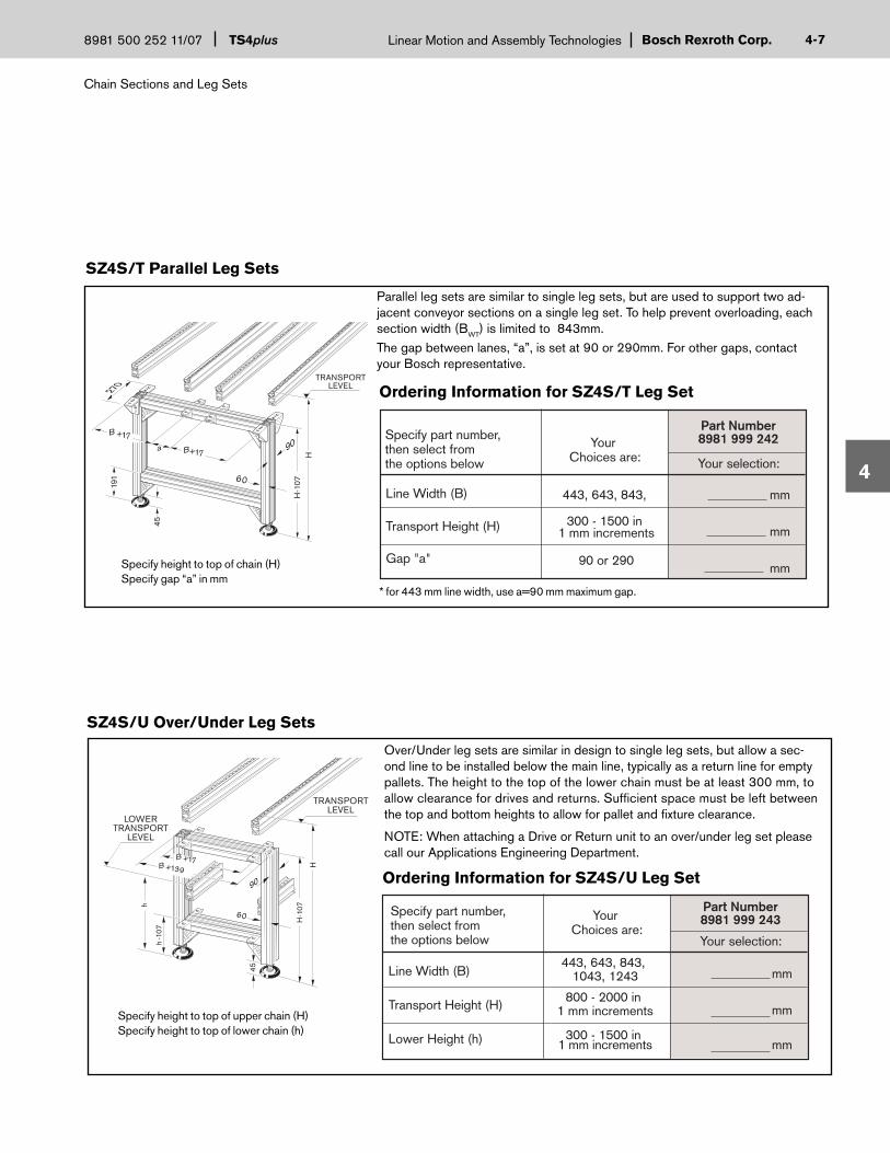
Parallel leg sets are similar to single leg sets, but are used to support two ad-jacent conveyor sections on a single leg set. To help prevent overloading, each section width (BWT) is limited to 843mm.The gap between lanes, “a”, is set at 90 or 290mm. For other gaps, contact your Bosch representative.
* for 443 mm line width, use a=90 mm maximum gap.
Specify height to top of chain (H)Specify gap “a” in mm
Ordering Information for SZ4S/T Leg Set
Line Width (B)
Transport Height (H)
Gap "a"
443, 643, 843,
300 - 1500 in 1 mm increments
90 or 290
Part Number8981 999 242
Your selection:
Your Choices are:
Specify part number,then select fromthe options below
mm
mm
mm
7
SZ4S/T Parallel Leg Sets
HH
-107
45
191
TRANSPORTLEVEL
B+17a
B +17
60
90
270
Over/Under leg sets are similar in design to single leg sets, but allow a sec-ond line to be installed below the main line, typically as a return line for empty pallets. The height to the top of the lower chain must be at least 300 mm, to allow clearance for drives and returns. Suffi cient space must be left between the top and bottom heights to allow for pallet and fi xture clearance.
NOTE: When attaching a Drive or Return unit to an over/under leg set please call our Applications Engineering Department.
TRANSPORTLEVEL
H-1
07
H
45
h-1
07
LOWERTRANSPORT
LEVEL
h
B +17B +139
60
90
Specify height to top of upper chain (H)Specify height to top of lower chain (h)
Line Width (B)
Transport Height (H)
Lower Height (h)
443, 643, 843, 1043, 1243
800 - 2000 in 1 mm increments
300 - 1500 in 1 mm increments
Part Number8981 999 243
Your selection:
Your Choices are:
Specify part number,then select fromthe options below
mm
mm
mm
SZ4S/U Over/Under Leg Sets
Ordering Information for SZ4S/U Leg Set

Chain Sections and Leg Sets
TS4plusLinear Motion and Assembly Technologies 8981 500 252 11/07Bosch Rexroth Corp.4-
4
The steel foundation bracket secures the leg set to the fl oor after the conveyor has been leveled and aligned. Two foundation brackets should be used for each leg set. Two T-bolt kits for fastening the founda-tion bracket to the leg set are included. Anchor bolts for securing the bracket to concrete fl oors are ordered separately.
Anchor Bolt
210
90
42
Ordering Information for Foundation Brackets
71
65
8
8
Foundation Brackets and Anchor Bolts
Steel Foundation Bracket with two T-Bolt Kits 8981 003 224 Anchor Bolt, one (1) 3842 526 560
Description
8
Anchor Bolt Dimensions
Part Number
SZ2 Single Leg Sets (for mounting to BS4 Transverse Conveyors)
Ordering Information for SZ2 Leg Set
Line Width (B)
Profile Depth
Transport Height (H)
443, 643, 843, 1043, 1243
100mm
350 - 1500 in 1 mm increments
Part Number3842 999 816
Your selection:
Your Choices are:
Specify part number,then select fromthe options below
mm
mm
mm
100B – 75
45 180
100
PD
H
60
B + 15Beltor
ChainHeight
142
45
SZ2/H Heavy Duty Single Leg Sets (for mounting to BS4 Transverse Conveyors)
Ordering Information for SZ2/H Leg Set
Line Width (B)
Profile Depth
Transport Height (H)
443, 643, 843, 1043, 1243
100mm
350 - 1500 in 1 mm increments
Part Number3842 999 705
Your selection:
Your Choices are:
Specify part number,then select fromthe options below
mm
mm
mm
100B – 75
45 180
100
H
PD
60
B + 15Beltor
ChainHeight
23245
Specify height to top of chain (H)
Specify height to top of chain (H)
Bosch Rexroth Corp.Linear Motion and Assembly Technologies
Transverse conveyors
TS4plus8981 500 252 11/07 5-
5
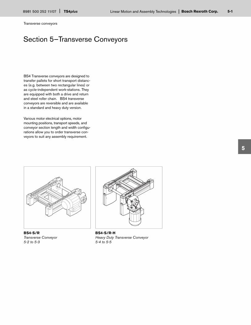
BS4 Transverse conveyors are designed to transfer pallets for short transport distanc-es (e.g. between two rectangular lines) or as cycle-independent work-stations. They are equipped with both a drive and return and steel roller chain. BS4 transverse conveyors are reversible and are available in a standard and heavy duty version.
Various motor electrical options, motor mounting positions, transport speeds, and conveyor section length and width confi gu-rations allow you to order transverse con-veyors to suit any assembly requirement.
Section 5—Transverse Conveyors
BS4-S/R-HHeavy Duty Transverse Conveyor5-4 to 5-5
BS4-S/RTransverse Conveyor5-2 to 5-3
1

Transverse conveyors
TS4plusLinear Motion and Assembly Technologies 8981 500 252 11/07Bosch Rexroth Corp.5-
5
Transverse Conveyors
Roller chain transverse conveyors are used to transfer heavy workpiece pal-let payloads between parallel conveyor sections. They are also used to construct cycle-independent workstations and are especially suitable for modular system layouts with short conveyor sections at high loads. The unit itself is modular and comes with its own drive, return, and preinstalled roller chain.
In normal operation, the maximum load ca-pacity for the BS4-S/R is 200kg and 100kg in reverse. The unit uses steel roller chain as the conveying medium and is de-livered with a spring chain tensioning device.
Ordering Information for BS4-S/R
* Full load conveyor speeds vary depending on motor frequency. See table 5-1† Transverse conveyors 2000mm long must be supported by a leg set. See page 4-8
Motor Position
270˚
180˚
90˚
0˚
Outboard MountedMotor Orientation
PalletFlow
PalletFlow
R
L
M
200
NOTE: When reverse operation is specifi ed, a fi xed chain tensioner is used instead of the spring tensioner.
Motor voltage and frequency selections are described in Table 5-1. All motors include CE compliant wiring terminals.
The unit comes fully assembled. Mount-ing hardware in not included. Three different connection kits are available depending on the module the BS4-S is being mounted to.
Please contact our applications engineer-ing department for nonstandard length, width, speed, or voltage.
Model BS4-S/R
The roller chain transverse conveyor is available in lengths from 400mm to 6000mm in 5mm increments. Specify conveyor width, length, conveyor speed, motor voltage/frequency, motor position, reverse option, and motor orientation when ordering.
Ordering Information for BS4-S Connection Kits
Description Part Number
BS4-S to AS4-S/UM4-S Connection Kit 3842 530 871
BS4-S to ST4-S Connection Kit 3842 530 868
BS4-S to BS4-S Connection Kit 3842 528 192
2
See Table 5-1
R, M, L
YES with fixed tensionerNO with spring tensioner
9, 12, 15, 18
____________ mm
_______________
_______________
_______________
____________ m/mm
____________ mm
________ V ________ Hz
443, 643, 843, 1043, 1243
400mm to 6000mm†
(in 5 mm increments)
Width (B) in mm
Motor Position
Motor Orientation (outboard mount only)
Reverse Operation
Transverse Conveyor length (L)†
Nominal Conveyor Speed (m/min)*
Motor Voltage/Frequency
Part Number3842 998 097Your
Choices are:
Specify part number,then select fromthe options below Your selection:

Bosch Rexroth Corp.Linear Motion and Assembly Technologies
Transverse conveyors
TS4plus8981 500 252 11/07 5-
5
Electrical Data for BS4-S/R
Technical Data for BS4-S/R
Dimensional Data for BS4-S/R
Transverse conveyor width (B) must match pallet length (LWT) or width (BWT), depending on orientation.
Nominal conveyor speed Load capacity forwardLoad capacity reverse Motor RPM @ 50 HzMotor RPM @ 60HzMotor electrical specifications
= See Table 5-1 = 200 kg= 100 kg = 1400= 1700= See Table 5-1
Nom.M/min
9121518
.25
.25
.25
.25
208/601.61.61.61.6
240/601.31.31.31.3
380/500.860.860.860.86
415/500.720.720.720.72
480/600.670.670.670.67
575/600.550.550.55 0.55
Full Load Amps @Actual Speed
50 Hz9.511.514.319.1
60 Hz8.711.613.917.4
HP
Table 5-1 Note: Electrical Data for reference only. Refer to motor name plate for actual amperage ratings.
BOSCH
306.
4
107
170L
60
124.
4
B+
40
B+
40
B+
2
B+
2
B-1
00
B-1
00
61.6
8B
-75
69
3

Transverse conveyors
TS4plusLinear Motion and Assembly Technologies 8981 500 252 11/07Bosch Rexroth Corp.5-
5
Heavy Duty Transverse Conveyors
Ordering Information for BS4-S/R-H BS4-S/R-HS4-S/R-H S4-S/R-H
Model BS4-S/R-H
Heavy Duty Roller chain transverse con-veyors utilize a gearmotor and are used to transfer heavy workpiece pallet payloads between parallel conveyor sections. They are also used to construct cycle-indepen-dent workstations and are especially suit-able for modular system layouts with short conveyor sections at high loads. The unit itself is modular and comes with its own drive, return, and preinstalled roller chain.
In normal operation, the maximum load capacity for the BS4-S/R-H is 450kg and 225kg in reverse. The unit uses steel roller chain as the conveying medium and is de-livered with a spring chain tensioning device.
The roller chain transverse conveyor is available in lengths from 400mm to 6000mm in 5mm increments. Specify conveyor width, length, conveyor speed, motor voltage/frequency, motor position, reverse option, and motor orientation when ordering.
Motor voltage and frequency selections are described in Table 5-2. All gearmotors include CE compliant wiring terminals.
The unit comes fully assembled. Mounting hardware in not included. Three different connection kits are available depend-ing on the module the BS4-S is being mounted to.
Please contact our applications engineer-ing department for nonstandard length, width, speed, or voltage.
450
* Mid-mounted motor not available with BS4-S/R-H transverse conveyors.
4
NOTE: When reverse operation is specifi ed, a fi xed chain tensioner is used instead of the spring tensioner.
Motor Position
270˚
180˚
90˚
0˚
Outboard MountedMotor Orientation
PalletFlow
PalletFlow
R
L
Ordering Information for BS4-S Connection Kits
Description Part Number BS4-S to AS4-S/UM4-S Connection Kit 3842 530 871
BS4-S to ST4-S Connection Kit 3842 530 868
BS4-S to BS4-S Connection Kit 3842 528 192
** Full load conveyor speeds vary depending on motor frequency. See Table 5-2 † Transverse conveyors 2000mm long must be supported by a leg set. See page 4-8
See Table 5-2
R, L
YES with fixed tensionerNO with spring tensioner
9, 12, 15, 18
____________ mm
_______________
_______________
_______________
____________ m/mm
____________ mm
________ V ________ Hz
443, 643, 843, 1043, 1243
400mm to 6000mm †(in 5 mm increments)
Width (B) in mm
Motor Position*
Motor Orientation
Reverse Operation
Transverse Conveyor length (L) †
Nominal Conveyor Speed (m/min)**
Motor Voltage/Frequency
Part Number3842 999 901Your
Choices are:
Specify part number,then select fromthe options below Your selection:

Bosch Rexroth Corp.Linear Motion and Assembly Technologies
Transverse conveyors
TS4plus8981 500 252 11/07 5-
5
Actual SpeedNom.M/min
Full Load Amps/HP@
50 Hz
9121518
9.812.314.918.3
9.111.714.717.9
2.42.42.42.4
1/21/21/21/2
2.42.42.42.4
1/21/21/21/2
1.61.61.21.2
1.71.71.21.2
3/43/41/21/2
3/43/41/21/2
1.21.21.21.2
5/85/85/85/8
5/85/85/85/8
1.01.01.01.0
60 Hz 208/60 240/60 380/60 415/50 480/60 575/60AMPS AMPS AMPS AMPS AMPSHP HP HPHPAMPS HP HP
Electrical Data for BS4-S/R-H
Technical Data for BS4-S/R-H
Dimensional Data for BS4-S/R-H
Transverse conveyor width (B) must match pallet length (LWT) or width (BWT), depending on orientation.
Nominal conveyor speed Load capacity forwardLoad capacity reverse Motor RPM @ 50 HzMotor RPM @ 60HzMotor electrical specifications
= See Table 5-2 = 450 kg= 225 kg = 1380-1410= 1656-1728 = See Table 5-2
Table 5-2Note: Electrical Data for reference only. Refer to motor name plate for actual amperage ratings.
59
373.7
59
138
13840
17060
273.
5
107
160
61.7
78.5
147.
5
B+
40
B+
2
B+
187.
5
L
B-7
5
B-1
00
A A
View AA
5

Lift-Transfer Modules
TS4plusLinear Motion and Assembly Technologies 8981 500 252 11/07Bosch Rexroth Corp.6-
6
Section 6—Lift-Transfer Modules
HQ4Lift-Transfer Unit 6-2 to 6-4
TS4plus lift-transfer units permit the trans-fer of pallets between parallel conveyor lines. They lift the pallet above the roller chain surface and transfer it perpendicu-lar to the main line with a fl at-top chain conveyor segment.
Depending on the application, the pallet is transferred either across track rollers
TR4-STrack Rollers6-9 to 6-11
WI4-S/100, WI4-S/250 Cushioned Transfer Stop for HQ46-5 to 6-8
(for transfer between two closely spaced parallel lines) or to another conveyor chain section (for greater distances or shunt lines).
Two common line layouts are shown on the next page to demonstrate common HQ4 applications.
0

Bosch Rexroth Corp.Linear Motion and Assembly Technologies
Lift-Transfer Modules
TS4plus8981 500 252 11/07 6-
6
This layout uses two pairs of lift-transfer units, each connected with a set of track rollers.
Rectangular LayoutThis layout uses two pairs of lift-transfer units connected by in-line conveyor or transverse sections.
Parallel Layout
1

Lift-Transfer Modules
TS4plusLinear Motion and Assembly Technologies 8981 500 252 11/07Bosch Rexroth Corp.6-
6
Lift-Transfer Unit
Ordering Information for Lift-Transfer Unit HQ4
Table 6-1
Transfer StopsNot Included.
See page 6-5 to 6-8for ordering information.
* 270° motor orientation are only available when BQ > 643** Full load conveyor speeds vary depending on motor frequency. See Table 6-2
The HQ4 Lift-Transfer Unit is used to stop, lift, and transfer pallets at 90° angles in re-lation to the main conveyor direction. They are used at corners and along the line any time a pallet must be directed off the main conveyor. The lift transfer unit is securely mounted to the conveyor rails. The unit does not require leg posts, which allows it to be used with multi-level layouts.
The HQ4 uses fl at-top chain to transfer the pallet and is bi-directional. The lift transfer unit utilizes three-position, spring-centered pneumatic lift cylinders. In the center, or “stop” position, the fl at-top chains are 10 mm below the transport level. In this position, pallets are stopped on their trailing edge by a cushioned trans-fer stop. To allow stopped pallets to pass through, the cylinders are energized and the HQ4 lowers 10 mm, allowing pallets to pass over the stop.
To receive or send a pallet onto a perpen-dicular line, the cylinders lift the pallet 23 mm. As the unit rises, the fl at-top chains engage the pallet and transfer it on or off the main conveyor.
Proximity switches can be used to detect the upper and lower positions of the HQ4. Two proximity switch brackets and exciter elements are included. Proximity switches are ordered separately. For sending or re-ceiving of pallets, a cushioned transfer stop (ordered separately on page 6-5) must be used to stop the pallet on the HQ4.
The lift mechanism is synchronized to pro-vide precise movement and a fl ow control is included for smooth lifting of the pallet. The HQ4 uses standard pushlock pneu-matic connections and requires a minimum pressure of 4 bar (58 psi) of fi ltered, oiled or unoiled, compressed air. All required mounting hardware is included.
NOTE: Please consult our application engineering department for mid-mounted motor options.
Model HQ4
HQ4 Available Sizes
2
Motor Position
PalletFlow
R
L
270˚
180˚
0˚
Outboard MountedMotor Orientation
Primary PalletFlow
See Table 6-2
See Table 6-1
See Table 6-1
R, L
9, 12, 15, 18
_____________
_________ m/mm
___________ mm
_____ V ____ Hz
18 27
Mounting Location
Lift Transfer Unit Length (BL)
Lift Transfer Unit Width (BQ)
Motor Position
Motor Orientation (outboard)*
Nominal Speed (m/min)
Part Number3842 998 035
YourChoices are:
Specify part number,then select fromthe options below
Motor Voltage/Frequency**
ST4-S: Mainline Conv.BS4-S: Transverse Conv. ______________
___________ mm
___________ mm
Your selection:
Tran
sfer
Leng
th,(
BL)
Transfer Width, (BQ)
643
843
1043
1243
••
••••
••••
••••
•••
443 643 843 1043 1243

Bosch Rexroth Corp.Linear Motion and Assembly Technologies
Lift-Transfer Modules
TS4plus8981 500 252 11/07 6-
6
Technical Data for HQ4
Cylinder Bore = 63 mm Cylinder Stroke = 33 mmOperating Pressure = 4–6 bar (58–87psi ) Lift Above Chain: = 13 mm Air Fittings = 8mm Pushlock (5/32”)
Electrical Data for HQ4
Dimensional Data for HQ4
3
Nom.M/min
9121518
.25
.25
.25
.25
208/601.61.61.61.6
240/601.31.31.31.3
380/500.860.860.860.86
415/500.720.720.720.72
480/600.670.670.670.67
575/600.550.550.55 0.55
Full Load Amps @Actual Speed
50 Hz9.010.713.417.9
60 Hz8.210.913.016.3
HP
Table 6-2Note: Electrical Data for reference only. Refer to motor data plate for actual ratings.
NOTE: See Page 6-4 for additional HQ4 dimension drawings
1) Transport level (ST4 or BS4)
2) Lower position (Pass-Through) = 20mm below transport level.
3) Center position (Stop) = 10mm below transport level.
4) Upper position (Transfer) = 13mm above transport level.
BQ -131.593.5
16
BQ +33
100
242.
5
304.
75
451)
4) 3)2)
BQ +2
BQ -75
BQ -91
131
131
ST
4 =
BL
-261
BS
4 =
BL
-233
ST
4 =
BL
-103
367
34.8
BS
4 =
BL
-75
60

Lift-Transfer Modules
TS4plusLinear Motion and Assembly Technologies 8981 500 252 11/07Bosch Rexroth Corp.6-
6
BQ
-129
ST4 = BL -299BS4 = BL -271
BL
Dimensional Data for HQ4
4

Bosch Rexroth Corp.Linear Motion and Assembly Technologies
Lift-Transfer Modules
TS4plus8981 500 252 11/07 6-
6
Cushioned Transfer Stop for HQ4
Ordering Information for WI4-S/100
Cushioned transfer stops are used to stop workpiece pallets that are being sent (or received) onto an HQ4 lift-transfer unit. They are designed to be mounted inside a lift-transfer unit and can be used for either sending or receiving, depending on mounting location.
The WI4-S/100 cushioned transfer stop is designed for pallet loads between 5kg and 100kg. The WI4-S/250 heavy duty cushioned transfer stop is designed for payloads between 25kg and 250kg. Damping effect for various payload and speed combinations is set via an adjust-ment screw.
Models WI4-S/100, WI4-S/250
5
443
643
843
1043
1243
443
643
843
1043
1243
Line Width (B)in mm
Part NumberConveyor SectionType
ST4
ST4
ST4
ST4
ST4
BS4
BS4
BS4
BS4
BS4
8981 022 100
8981 022 101
8981 022 102
8981 022 103
8981 022 104
8981 022 105
8981 022 106
8981 022 107
8981 022 108
8981 022 109
443
643
843
1043
1243
443
643
843
1043
1243
Line Width (B)in mm
Part NumberConveyor SectionType
ST4
ST4
ST4
ST4
ST4
BS4
BS4
BS4
BS4
BS4
8981 022 110
8981 022 111
8981 022 112
8981 022 113
8981 022 114
8981 022 115
8981 022 116
8981 022 117
8981 022 118
8981 022 119
Two styles of cushioned transfer stops are available for HQ4 lift transfer units that are mounted either inside an ST4 mainline conveyor section or inside a BS4 trans-verse conveyor module. NOTE: Different part numbers exist for each style and line width.
All required mounting hardware is in-cluded. The stop is shipped unassembled. It includes a 8mm pushlock pneumatic fi tting and requires 4-6 bar of fi ltered oiled or unoiled, compressed air.
Ordering Information for WI4-S/250

Lift-Transfer Modules
TS4plusLinear Motion and Assembly Technologies 8981 500 252 11/07Bosch Rexroth Corp.6-
6
Application Examples for Cushioned Stops
BQ BL
BL
BL
Sending
Sending and Receiving
Receiving
6

Bosch Rexroth Corp.Linear Motion and Assembly Technologies
Lift-Transfer Modules
TS4plus8981 500 252 11/07 6-
6
A
A
A-A
30
63
9030
D
A
BQ
BL
A
AA-AA
D 30
3090
A (mm)2944946948941094
A (mm)3225227229221122
BL (mm)44364384310431243
D (mm)131231331431531
EQ4 mountedin ST4
EQ4 mountedin BS4
Dimensional Data for Cushioned Stops-Sending
WI4-S/100 - Sending
WI4-S/250 - Sending
WI4-S/100, WI4-S/250 - Sending
7

Lift-Transfer Modules
TS4plusLinear Motion and Assembly Technologies 8981 500 252 11/07Bosch Rexroth Corp.6-
6
29
A
A
A-A
9030
D90
15
A
BQ
BL
29
A
A
A-A
9030
A
A (mm)2944946948941094
A (mm)3225227229221122
BL (mm)44364384310431243
D (mm)161.5261.5361.5461.5561.5
EQ4 mountedin ST4
EQ4 mountedin BS4
BQ (mm)44364384310431243
WI4-S/100- Receiving
WI4-S/250 - Receiving
WI4-S/100, WI4-S/250 - Receiving
8
Dimensional Data for Cushioned Stops-Receiving

Bosch Rexroth Corp.Linear Motion and Assembly Technologies
Lift-Transfer Modules
TS4plus8981 500 252 11/07 6-
690 mm
290 mm
490 mm
690 mm
Conveyor Gap "a"
Part NumberUse when BWT is
> 643 mm
> 843 mm
> 843 mm
> 1043 mm
8981 021 950
8981 021 951
8981 021 952
8981 021 953
90 mm
290 mm
490 mm
690 mm
Conveyor Gap "a"
Part NumberQuantity
ConnectorKits required
Quantity ofCross Links
required
none
1
2
2
none
4
2
2
N/A
3842 992 491/...mm*
3842 990 584/...mm*
3842 990 584/...mm*
Track Rollers
Track rollers are non-powered and are used in conjunction with lift transfer units to support the pallet as it traverses the gap between parallel conveyor lines. They are available in 4 lengths, depending on pal-let width (BWT).
Mounting brackets and T-bolts are included; cross links and cross link con-nector kits must be ordered separately. Refer to the ordering chart below for the part number, length, and quantity required for each track roller size.
NOTE: To ensure suffi cient surface contact between the pallet wear strips and sending/receiving HQ4 lift-transfer units, TR4-S track rollers are only to be used with pallet widths (Bwt) > 643. For pallet widths of < 643mm, BS4 transverse conveyors, with a minimum length of 400mm, are required in place of track rollers.
See pages 6-10 and 6-11 for detailed dimensional data.
Ordering Information for Track Rollers TR4-S
Ordering Information for Track Roller Cross Links
* Specify length of cross link required where ... = (LWT- 103)
Model TR4-S
9
Order Cross Links seperately
Cross LinkConnector Kit
"a"
Lwt – 103
Cross Link Connector Kit
Description Qty Part Number
1 3842 146 972
Ordering Cross Link Connector Kits

Lift-Transfer Modules
TS4plusLinear Motion and Assembly Technologies 8981 500 252 11/07Bosch Rexroth Corp.6-
6
Conveyor gap “a” = 490 or 690mm
Track Rollers
Conveyor gap “a” = 290 mm
Dimensional Data for TR4-S
10
490 or 690
LWT + 2
11060
Cross Link LengthLWT – 103
LWT + 2
11060
Cross Link LengthLWT – 103
290

Bosch Rexroth Corp.Linear Motion and Assembly Technologies
Lift-Position Modules
TS4plus8981 500 252 11/07 7-
7
Section 7—Lift-Position Modules
TS4plus Lift-Position Units precisely position the workpiece pallet for various manufacturing processes.
The PE4 uses pneumatic cylinders to raise the pallet 18mm above the moving roller chain surface.
Positioning pins and synchronization shafts provide positioning accuracy of up to +0.125mm.
PE4Lift-Position Units7-2 to 7-3
1

Lift-Position Modules
TS4plusLinear Motion and Assembly Technologies 8981 500 252 11/07Bosch Rexroth Corp.7-
7
Lift-Position Units
Table 6-3
Ordering Information for Lift Transfer Unit PE4
The PE4 Lift-Position Unit accurately positions a workpiece pallet by lifting it vertically off a conveyor, isolating it from the moving roller chain. Pallet positioning repeatability is up to ±0.125 mm when station mounted (attached to separate leg posts or a machine base) and anchored to the fl oor. The PE4 mounts directly to ST4 conveyor sections or a BS4 transverse conveyor module.
The PE4 raises and lowers pallets with four double acting lift cylinders. Uniform lift is maintained through a series of rack and pinion gears between the lift cylinders. The PE4 lifts the pallet 18 mm above the roller chain. This reduces operator risk by minimizing potential pinch points between the pallet and the conveyor line.
Two 12 mm proximity switches can be used to sense the upper and lower posi-tions of the PE4. Two proximity switch mounting brackets and exciter elements are included. VE4-S cushioned stop gates must be used at all PE4 locations to stop pallets on the leading edge. Stop gates and proximity switches are not included but are available separately (see Section 7).
The PE4 uses standard 8mm pushlock pneumatic connections and requires a minimum pressure of 4 bar (58 psi) of fi l-tered, oiled or unoiled, compressed air. All required mounting hardware is included.
Model PE4
PE4 Available Sizes
Leng
th (
L WT)
Width (BWT)
443
643
843
1043
1243
••• •
••
•••••
•••••
••••
443 643 843 1043 1243
2
Mounting Location
Part Number3842 998 067Your
Choices are:
Specify part number,then select fromthe options below
_______________
____________ mm
____________ mm
See Table 6-3
See Table 6-3
Pallet width (BWT)
Pallet length (LWT)
ST4-S: Mainline ConveyorBS4-S: Transverse Conveyor
Your selection:

Bosch Rexroth Corp.Linear Motion and Assembly Technologies
Lift-Position Modules
TS4plus8981 500 252 11/07 7-
7
Cylinder Bore = 63 mmCylinder Stroke = 33 mmOperating Pressure = 4–6 bar (58–87 psi)Lift Above Chain = 18 mmRepeatability = ±0.125 mmMax. allowable applied force = 1100N (incl. WT4 payload)Air Fittings: = 8mm pushlock (5/32”)
Dimensional Data for PE4
Technical Data for PE4
LWT -212
LWT -106 0.1
BW
T-11
4.5
BW
T-22
9
0.1
0
LWT -345
LWT -174
LWT -46
15.5
15.5
145.5
145.
528
60
28
BW
T-26
1
ST
4 =
BW
T-10
3 B
S 4
= B
WT-
75
LWT -210.5
BW
T -15
7
BWT -46
BW
T-43
216
157.515
10
13
3)1)
2)018
15
33
3
1) Transport level (ST4 or BS4)
2) Lower position = 15mm below transport level.
3) Upper position = 18mm above transport level.

Traffi c Control
TS4plusLinear Motion and Assembly Technologies 8981 500 252 11/07Bosch Rexroth Corp.8-
8
Section 8—Traffi c Control
VE4-D250Heavy Duty Cushioned Stop Gates8-4 to 8-5
Controlling the fl ow of pallets to prevent excessive accumulation or maximize man-ual and automated workstation effi ciency takes a variety of approaches. TS4plus offers several types of stop gates, as well as proximity switches and switch mounting kits, to provide the most effective traffi c control system for your application.
VE4-S/ARAnti-rebound Stop8-1
Proximity Switch Bracket8-8
Proximity Switches8-8
Cushioned stop gates are used for all applications along a mainline conveyor line or transverse conveyor section.
All TS4plus cushioned stops utilize infi nitely adjustable, self-compensating pneumatic dampers to gently stop the workpiece pallet.
VE4-D100Cushioned Stop Gates8-2 to 8-3
Safety Stop Kit8-6
0
WI/MMini Rocker8-9
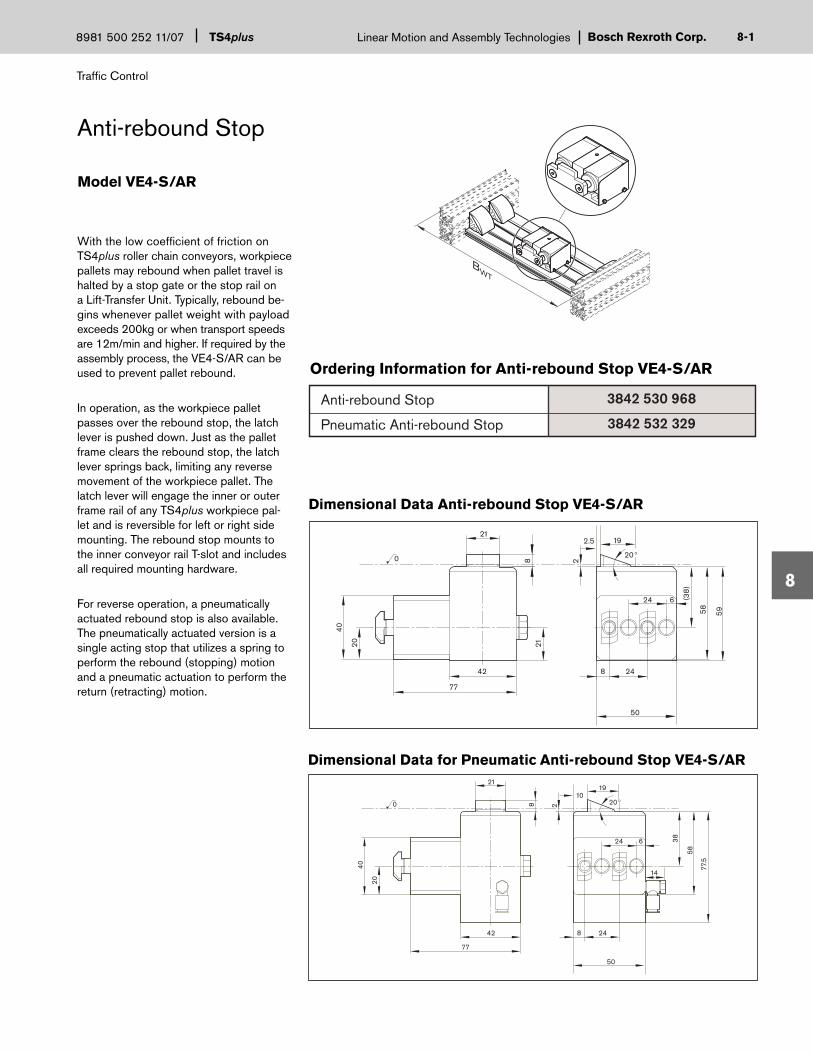
Bosch Rexroth Corp.Linear Motion and Assembly Technologies
Traffi c Control
TS4plus8981 500 252 11/07 8-
8
Ordering Information for Anti-rebound Stop VE4-S/AR
With the low coeffi cient of friction on TS4plus roller chain conveyors, workpiece pallets may rebound when pallet travel is halted by a stop gate or the stop rail on a Lift-Transfer Unit. Typically, rebound be-gins whenever pallet weight with payload exceeds 200kg or when transport speeds are 12m/min and higher. If required by the assembly process, the VE4-S/AR can be used to prevent pallet rebound.
In operation, as the workpiece pallet passes over the rebound stop, the latch lever is pushed down. Just as the pallet frame clears the rebound stop, the latch lever springs back, limiting any reverse movement of the workpiece pallet. The latch lever will engage the inner or outer frame rail of any TS4plus workpiece pal-let and is reversible for left or right side mounting. The rebound stop mounts to the inner conveyor rail T-slot and includes all required mounting hardware.
For reverse operation, a pneumatically actuated rebound stop is also available. The pneumatically actuated version is a single acting stop that utilizes a spring to perform the rebound (stopping) motion and a pneumatic actuation to perform the return (retracting) motion.
Anti-rebound Stop
Model VE4-S/AR
Anti-rebound Stop
Pneumatic Anti-rebound Stop
3842 530 968
3842 532 329
1
Dimensional Data Anti-rebound Stop VE4-S/AR
8
38
58
77.5
2
20
40
21
42 8 24
24 6
77
0 20
50
1910
14
21
(38
)
58 59
20
40
8 2
20
21
42 8 24
24 6
77
0
50
192.5
Dimensional Data for Pneumatic Anti-rebound Stop VE4-S/AR
BWT

Traffi c Control
TS4plusLinear Motion and Assembly Technologies 8981 500 252 11/07Bosch Rexroth Corp.8-
8
Cushioned Stop Gates
Center-mount cushioned stop gates are used to stop and separate workpiece pallets on the conveyor. They are pneu-matically reset and mounted between the conveyor section by attaching the mounting plate with gussets to the inner T-slot of the conveyor rails.
Cushioned stop gates are available for mounting to either ST4 mainline conveyor sections or to BS4 transverse conveyor sections. NOTE: Different part numbers exist for each style and line width.
The VE4/D100 cushioned stop gate is de-signed for pallet loads between 5kg and 100kg. When delivered, cushioned stop gates are confi gured to stop the pallet on the leading edge. However, they can be converted at any time (with no additional parts needed) to stop the pallet on its trailing edge. Damping effect for various payload and speed combinations is set via an adjustment screw.
All required mounting hardware is included. Cushioned stop gates include 8 mm pushlock pneumatic fi ttings and re-quire 4–6 bar of fi ltered, oiled or unoiled, compressed air.
Ordering Information for Cushioned Stop Gates, VE4/D100
BWT
Model VE4/D100
443
643
843
1043
1243
443
643
843
1043
1243
Line Width (BWT)in mm
Part NumberConveyor SectionType
ST4
ST4
ST4
ST4
ST4
BS4
BS4
BS4
BS4
BS4
8981 022 133
8981 022 134
8981 022 135
8981 022 136
8981 022 137
8981 022 138
8981 022 139
8981 022 140
8981 022 141
8981 022 142
2

Bosch Rexroth Corp.Linear Motion and Assembly Technologies
Traffi c Control
TS4plus8981 500 252 11/07 8-
8
3.5
8
0
ST4ST4
B+2
180
22.5
77.5
90
118
138
(B/2) -81.5 (ST4)
(B/2) -67.5 (BS4)
90
132
B-103 (ST4)
B-75 (BS4)
Cushioned Stop Gates
Dimensional Data for VE4/D100
Stop Load Ratings for VE4/D100
3
NOTE: Once a cushioned stop gate has been compressed by a workpiece pallet, “Accumulation” refers to any subsequent pallets that queue up behind the fi rst pallet.
Accumulation Load Ratings for VE4/D100
6 m/min 9 m/min 12 m/min 15 m/min
100 Kg 100 Kg 100 Kg 95 Kg
18 m/min
90 Kg
6 m/min 9 m/min 12 m/min 15 m/min
1000 Kg 800 Kg 500 Kg 300 Kg
18 m/min
200 Kg

Traffi c Control
TS4plusLinear Motion and Assembly Technologies 8981 500 252 11/07Bosch Rexroth Corp.8-
8
Heavy Duty Cushioned Stop Gates
Heavy Duty center-mount cushioned stop gates are used to stop and separate workpiece pallets on the conveyor. They are pneumatically reset and mount be-tween the conveyor section by attaching the mounting plate with gussets to the inner T-slot of the conveyor rails.
Cushioned stop gates are available for mounting to either ST4 mainline conveyor sections or to BS4 transverse conveyor sections. NOTE: Different part numbers exist for each style and line width.
The VE4/D250 cushioned stop gate is de-signed for pallet loads between 30kg and 250kg. When delivered, cushioned stop gates are confi gured to stop the pallet on the leading edge. However, they can be converted at any time (with no additional parts needed) to stop the pallet on its trailing edge. Damping effect for various payload and speed combinations is set via an adjustment screw.
All required mounting hardware is included. Cushioned stop gates include 8mm pushlock pneumatic fi ttings and re-quire 4–6 bar of fi ltered, oiled or unoiled, compressed air.
Ordering Information for Heavy Duty Cushioned Stop Gates, VE4/D250
BWT
8981 022 143
8981 022 144
8981 022 145
8981 022 146
8981 022 147
8981 022 148
8981 022 149
8981 022 150
8981 022 151
8981 022 152
443
643
843
1043
1243
443
643
843
1043
1243
Line Width (BWT) Part Number Conveyor Section
ST4
ST4
ST4
ST4
ST4
BS4
BS4
BS4
BS4
BS4
Model VE4/D250
4

Bosch Rexroth Corp.Linear Motion and Assembly Technologies
Traffi c Control
TS4plus8981 500 252 11/07 8-
8
Dimensional Data for VE4/D250
Stop Load Ratings for VE4/D250
3.5
8
0
ST4 ST4 B+2
180
77.5
22.5
90
126.
5
150.
5
127
B-103 (ST4)B-75 (BS4)
(B/2)-81.5 (ST4) (B/2)-67.5 (BS4)
5
NOTE: Once a cushioned stop gate has been compressed by a workpiece pallet, “Accumulation” refers to any subsequent pallets that queue up behind the fi rst pallet.
Heavy Duty Cushioned Stop Gates
Accumulation Load Ratings for VE4/D250
6 m/min 9 m/min 12 m/min 15 m/min
250 Kg 250 Kg 250 Kg 235 Kg
18 m/min
225 Kg
6 m/min 9 m/min 12 m/min 15 m/min
2300 Kg 2000 Kg 1200 Kg 700 Kg
18 m/min
500 Kg

Traffi c Control
TS4plusLinear Motion and Assembly Technologies 8981 500 252 11/07Bosch Rexroth Corp.8-
8
Safety Stop Kit
The optional safety stop kit is not required but can be used as a redundant safety feature for the control system. The safety stop will prevent the workpiece pallet from being pushed from the end of the conveyor in the event of a control system failure. The stops attach to the T-slot in the conveyor rail next to the drive unit. The kit includes two stops and the required mounting hardware.
Ordering Information for Safety Stop Kit
25.4
22.5 12
0
19.1
Dimensional Data for Safety Stop Kit
Safety Stop Kit (for all pallet sizes)
Part Number
8981 020 069
6

Bosch Rexroth Corp.Linear Motion and Assembly Technologies
Traffi c Control
TS4plus8981 500 252 11/07 8-
8
Proximity Switches
Proximity switches indicate workpiece pallet presence by detecting the exciter plates on the sides of workpiece pal-lets. These normally open, 24 VDC, short-circuit protected switches are PNP (sourcing) and have a 12 mm threaded body. Proximity switches operate at a 4 mm sensing range (unshielded) and have an LED indicator.
Two versions are available. The standard switch has fi ve meters of three conduc-tor cable attached. The quick disconnect switch provides for faster assembly and service when used with the disconnect plug and cable.
Ordering Information Proximity Switches
NOTE: Proximity switches are not included with modules that require them and must be ordered separately. In some cases, proximity switch use is optional, depending on the control system programming.
Standard Proximity Switches
Part Number
8981 004 462
8981 533 326
8981 008 498
8981 013 317
Description
A
B
C
D
12mm, 10-30 VDC, normally open, Proximity Switch with 5m of 3 conductor cable, one
12 mm 10-30 VDC, normally open, Quick Disconect Proximity Switch, one
Straight, Quick Disconnect Plug with 5m of 3 conductor cable, one
90º Quick Disconnect Plug with 5m of 3 conductor cable, one
12 mmQuick DisconnectProximity Switch
90 QuickDisconnect Plugwith 5 m cable
Standard 12 mmProximity Switchwith 5 m cable
A.
D.
B.
QuickDisconnect Plugwith 5 m cable
C.
7
Quick Disconnect Proximity Switches

Traffi c Control
TS4plusLinear Motion and Assembly Technologies 8981 500 252 11/07Bosch Rexroth Corp.8-
8
Proximity Switch Bracket
Proximity switch mounting kits are used to attach proximity switches to sense the discrete pallet position along the line for control purposes. The switch, sold sepa-rately, is typically used to provide a “pallet present” signal at stops, transfers, and positioning modules.
The proximity switch bracket is designed to be used with any 12 mm diameter proximity switch. The bracket is constructed of tough polyamide and includes all mounting hardware.
NOTE: Proximity switches must be mounted at a minimum distance of 4mm from the exciter plate, which is located on the corner bumper of the pallet.
Ordering Information for Proximity Switch Bracket SH2/S
Dimensional Data for SH2/S
Model SH2/S
8
Horizontal Proximity Switch Bracket with mounting hardware
Part NumberDescription
amin = 4ø1
240
24
55.3
65.3 80
5.25
15.2
5
7.5
30
10.8
3842 168 830

Bosch Rexroth Corp.Linear Motion and Assembly Technologies
Traffi c Control
TS4plus8981 500 252 11/07 8-
8
Mini Rocker
The WI/M mini rocker stop provides an economical method of workpiece pallet detection. It can also be used (in conjunc-tion with other components) to create an accumulation control kit.
When used for pallet detection, a 12mm threaded body proximity switch is required (ordered seperately). The switch is acti-vated when a workpiece pallet passes in front of the rocker. In this confi guration, the WI/M has a monitoring area of 44mm.
When used for accumulation control, the WI/M is combined with a pneumatic cylinder switch. In this confi guration, the slide actuation is directly converted into a pneumatic signal. A pneumatic accumula-tion control kit can then be constructed with the use of a VE4 stop gate.
How an accumulation control kit works: when the rocker is in the rest position, air is directed to the stop gate and pallets freely pass through. When the rocker is actuated by a pallet, the air is disabled and the stop gate begins queuing pallets.
Ordering Information for Mini Rocker Stop, WI/M
Dimensional Data for WI/M
Model WI/M
Pneumatic Cylinder Switch
WI/M Rocker Module (Fastening Hardware Included)
Part NumberDescription
Pneumatic Cylinder Switch
19
91
14
44
60
10.5
29
31.5
37.5
9
3842 530 797
3842 532 151

Technical Data
TS4plusLinear Motion and Assembly Technologies 8981 500 252 11/07Bosch Rexroth Corp.9-
9
Section 9—TS4plus Technical Data
Conveyor width is determined by the size of the workpiece pallet. Maximum payload depends on the length of the load-bearing edge (Lwt or Bwt) of the workpiece pallet. Since workpiece pallet orientation chang-es at junctions in a parallel or rectangular confi guration, maximum permissible load-ing also changes, as shown at right.
Maximum permissible workpiece pallet payload (includes pallet, fi xturing, and workpiece) depends on the supported length of the pallet. See the illustration at right.
Never exceed the maximum load per pallet or per drive unit. The load is maximum when pallets are in queue.
Transportation speed
Preferred speed is 12m/min on conveyor sections and transfers. Performance data for individual modules is based on these speeds, although different speeds can be selected. Transportation speed is selected based on the system cycle time, time required by the workpiece pallet to enter a workstation, total weight of the pallet, and the stability of the workpiece on the pallet.
Conveying direction
Workpiece pallets should be conveyed toward a drive unit. Reversible operation is possible only when explicitly stated.
Transport Direction
85
125
165
210
250
443
643
843
1043
1243
Workpiece Palletload-bearing edgeLwt or Bwt in mm
MaximumLoad in kg*
* Maximum load is the combined weight of all pallet components, fi xture, and parts. Please refer to page 8-2 for application notes on pallet payloads as they relate to load application points.
WT4
LWT
BWT
d
Conveyor width
0
Workpiece pallet
Supported length
Conveyor section
Transport chain

Bosch Rexroth Corp.Linear Motion and Assembly Technologies
Technical Data
TS4plus8981 500 252 11/07 9-
9
Bwt Lwt Bwt Lwt
kg lbs. Center Center kg lbs. Center Center
443x1043 185 407.9 -0.052 -1.968 443x84 105 231.5 -0.124 -1.925
443x1243 105 231.5 -0.025 -1.933 443x1043 55 121.3 -0.053 -1.975
643x1243 155 341.8 -0.126 -1.963 443x1243843x1243 205 452.0 -0.396 -1.979 643x84 155 341.8 -0.626 -1.955
643x1043 80 176.4 -0.261 -1.976
643x1243
843x1043 105 231.5 -0.815 -1.977
843x1243 60 132.3 -0.281 -1.955
1043x1043 130 286.7 -1.977 -1.977
1043x1243 75 165.4 -0.958 -1.9741243x1243 90 198.5 -0.987 -1.987
Payload with 1/3 weight distribution on 3/4"(19.1 mm) pallets
Reduced AllowablePallet Weight
Reduced AllowablePallet Weight
Affected Pallet Sizes
Affected Pallet Sizes
Payload with 1/3 weight distribution on 1/2"(12.7 mm) pallets
Deflection (mm)
(Excessive deflection @ any load)
(Excessive deflection @ any load)
Deflection (mm)
The maximum payload of certain size pallets is subject to reduction due to excessive defl ection of the pallet plate. Defl ection must be limited to 2mm maximum as measured at the center point of the pallet plate. This defl ection value increases as the payload footprint decreases.
The following information is offered as a guideline for proper application of pay-load considerations. The calculated values shown below are based on a payload footprint equal to Bwt/3 x Lwt/3 (see diagram at right). Payload Footprint for Defl ection Values
Pallet Plate Loading and Defl ection
1. The footprint Bwt/3 x Lwt represents the smallest “normal” application, and is indicative of the outermost location of any piece-part tooling.
2. If you have a concentrated load on a small footprint as shown, the payload rating is reduced per the tables below.3. Pallet sizes not shown in table are capable of carrying their rated maximum payloads with a footprint BWT/3 x LWT/3
(consult the Bosch applications department for payloads with a footprint smaller than BWT/3 x LWT/3).4. Defl ection values are based on a MIC-6 Aluminum tooling plate with a raw material modulus of elasticity of 71000
Mpa minimum.5. In addition to payload defl ection considerations, pallets subject to external forces such as automated assembly op-
erations (i.e. at lift position units) must be supported properly to maintain pallet integrity. 6. Plate and fi xture geometry will affect defl ection values. Please contact the Bosch applications department to review
your particular requirements.
Application notes:
LWT
3
BW
T
3
1

Technical Data
TS4plusLinear Motion and Assembly Technologies 8981 500 252 11/07Bosch Rexroth Corp.9-
9
SPRING TENSIONER OPTION
THREADED TENSIONER OPTION
X
X
Dimension “X”
Minimum = 178 (New chain)
Maximum = 228 (Chain to be shortened)
Drive Unit Chain Tensioner Options
Two types of chain tensioners are available for both standard and heavy-duty drives.
The spring tensioner is recommended for most applications. When properly adjusted, the spring tensioner allows the chain tensioning shoe to fl oat ±21 mm from the nominal set-ting. This absorbs fl uctuations in chain slack caused by varying loads, and helps protect the chain from damage caused by unusual stresses such as debris in the chain. The overall shoe distance “X” is set at assembly (X= 178 mm) and must be adjusted periodi-cally to maintain proper tensioning. When the adjustment range of the tensioner is exhausted (X=228 mm), the chain must be shortened or replaced. A proximity switch can be installed to detect this service condition.
The threaded tensioner does not provide the same degree of protection from chain tension fl uctuations as the spring tensioner. However, it must be used in special applications, such as reversing systems or systems with a total length under 4000 mm. Set-up and mainte-nance are similar, but more frequent adjustment is necessary to avoid excessive slack in the chain. Again, when the adjustment range of the tensioner is exhausted, the chain must be shortened or replaced. A proximity switch can be installed to determine when shortening the chain is necessary.
2

Bosch Rexroth Corp.Linear Motion and Assembly Technologies
Technical Data
TS4plus8981 500 252 11/07 9-
9
3
Components that fall under the EC machinery guideline are provided upon request with the corresponding manufacturer’s declaration. Overall responsibility for system safety (decla-ration of conformity, CE identifi cation) lies with the system builder. The references in the assembly instructions must be followed.
Environmental conditions - climaticThe transfer systems have been designed for stationary use in a location that is protected from the elements.Operating temperature+5 to +40°C-5 to +60° with 20% less loadStorage temperature-25°C to +70°CRelative humidity5 to 85%, non-condensingAir pressure> 84 kPa appropriate height< 1400m above sea levelLoad values are reduced by 15% when the system is set-up at a location that is over 1,400m above sea level.
Environmental conditions - biologicalAvoid molds, fungi, rodents and other vermin.
Environmental conditions - chemicalDo not set up near industrial systems with chemical emissions.
Environmental conditions - physicalDo not set up near sandy or dusty sources. Do not set up in areas that are regularly jarred by high forces caused by equip-ment such as presses, heavy machinery etc.
CE Identifi cation, responsibility
Ambient conditions
The materials used in the components are primarily:
— Non-rusting steel or steel protected against corrosion by a special surface — Brass — Cast or malleable aluminum alloy — Polyurethane, polyamide, some with additives to improve electrical and mechanical characteristics and UHMW polyethylene— NBR or VITON for elastic seals
Media resistanceResistant to many common media used in production such as water, mineral oil, grease and detergents. Contact your Rexroth representative if you have any doubts about resistance to specifi c chemicals such as test oil, doped oils, aggressive detergents, solvents or brake fl uids. Avoid long-term contact with acidic or basic reacting materials.
ContaminationWear may increase dramatically if the system is contaminat-ed due to environmental factors, particularly with abrasive media such as sand and silicates but also due to processes running on the transfer system (e.g. welding beads, pumice dust, glass shards, shavings or lost parts...). In such cases, maintenance intervals must be substantially shortened.
Materials used
General System Information

Technical Data
TS4plusLinear Motion and Assembly Technologies 8981 500 252 11/07Bosch Rexroth Corp.9-
9
General System Information
Resistance to media and contamination does not mean that functional safety is guaranteed in every case.— Liquids that thicken on evaporation and are highly viscous or adhesive (sticky) could lead to a disruption in function.— Media with lubricating properties may reduce the driving power that is caused by friction if they are transported on systems with belts or round belts.— The chain lubricant used on conveyor chains can be washed away with solvents or detergents.
Such cases require special attention when planning the system and adjusting the maintenance intervals.
The materials used are environmentally sustainable and may be recycled or reused (if components are converted or replaced). Recyclability is ensured by the selection of material and the possibility to take the components apart.
Oiled or non-oiled, fi ltered, dry compressed airOperating pressure 4 to 8 barPerformance data is for an operating presuure of 5 bar.
The TS components require very little maintenance. Mainte-nance instructions are included in the operating manual.
Functional Safety
Environmental sustainability, recycling
Pneumatic connection data
Maintenance
Wear is caused by the basic principle of this system and cannot be avoided. Constructive measures and selection of the proper materials will help functional safety last for the lifetime of the system. However, wear depends on the op-erating, maintenance and ambient conditions of the system and the location (resistance, contamination).
The following measures reduce wear and the friction caused by it:— Switch off conveyor sections when the system is not running, e.g. during breaks, overnight, on the weekend.— Only select speeds that correspond to the particular function.— Minimize the weight of the workpiece pallet - do not over load with material during pickup.— Avoid unnecessary accumulation section, e.g. by reduc- ing the number of workpiece pallets.— Switch off accumulation sections that can carry heavy workpiece pallets if transport is not necessary— Especially important: Avoid contamination by abrasive media or reduce contamination with regular cleaning.
Permitted loads apply for conveyor sections only under the condition that workpiece pallets with the maximum permit-ted weight have accumulated. Higher loads are permitted if accumulation can be safely avoided. Accumulation opera-tion is not permitted on lift-transverse units.
Wear
Load specifi cations
Measures to reduce wear
4

Bosch Rexroth Corp.Linear Motion and Assembly Technologies
Technical Data
TS4plus8981 500 252 11/07 9-
9
5
ø 8mm
R
P
4-6 bar
ø 8mm
WI4-S/100, WI4-S/250Cushioned Transfer Stops
VE4-S/D100, VE4-S/D250Cushioned Stop Gates
Pneumatic Information
HQ4-SLift Transfer Unit
PE4-SLift Position Unit
2
45
3
1
4
2
5
13
Pneumatic Summary
Module
VE4-S/D100
VE4-S/D250
WI4-S/D100
WI4-S/D250
HP4-S
EQ4-S
Bore
25
40
35
40
63
63
Stroke
20
24
24
24
33
33
G1/8
G1/8
G1/8
G1/8
G1/8
G1/8
Volume per Stroke (liters)
0.01
0.03
0.02
0.03
0.41
0.41
Tube Size (mm)
8
8
8
8
8
8
Port
Not Included
Not Included
Not Included
Not Included
31
2
4-6 bar
Module
Pneumatic Cylinder Switch
Tube Size (mm)
barbed hose connector
Flow Rate
40l/min
Port
4
WI/M Pneumatic Cylinder Switch
5

Technical Data
TS4plusLinear Motion and Assembly Technologies 8981 500 252 11/07Bosch Rexroth Corp.9-
9
6
Metric/English Conversion Chart
Metric Tap/Drill Specifications TemperatureTap Tap Drill Size
M4 M4 x .7 3.3 mm
M5 M5 x .8 4.2 mm
M6 M6 x 1 5.0 mm
M8 M8 x 1.25 6.8 mm
M12 M12 x 1.75 10.2 mm
M16 M16 x 2 14.0 mm
Linear
Area
Volume
Acceleration
Velocity
Mass
Force
Pressure
Torque
Moment of Inertia
millimeters (mm)incheskilometers (km)milesmillimeters 2 (mm 2)inches 2
centimeters 3 (cm3)inches 3
1 cm3 = 1 milliliter (mL) , 1000 mL = 1 Litermeter/second 2 (m/s2)inch/second2
meter/second (m/s)feet/secondkilogram (kg)poundskilograms-f (kgf)Newtons (N)pounds-fNewtons (N)barPSINewton-Meters (Nm)pound-inchescentimeters 4 (cm4)inches 4
inchesmillimeters (mm)mileskilometers (km)inches2
millimeters 2 (mm 2)inches 3
centimeters 3 (cm3)
inch/second2
meter/second 2 (m/s2)feet/secondmeter/second (m/s)poundskilogram (kg)Newtons (N)kilograms-f (kgf)Newtons (N)pounds-fPSIbarpound-inchesNewton-Meters (Nm)inches 4 centimeters 4 (cm4)
0.0393725.40.62141.60930.00155645.160.0610216.387
39.370.02543.2810.30482.20460.45369.8070.101944.4480.224814.50.0698.8510.112980.0240341.623
Measurement Multiply by to get:
Degrees Celsius
Degrees Fahrenheit
5 x (degrees F - 32)9
(9 x degrees C) + 32
5
Power kilowatts (Kw)horsepower (HP)
horsepower (HP)kilowatts (Kw)
1.340.746
Energy Joules (J)foot/pounds (ft/lbs)
foot/pounds (ft/lbs)Joules (J)
0.73761.3558
Conversion Chart

Bosch Rexroth Corp.Linear Motion and Assembly TechnologiesTS4plus8981 500 252 11/07 10-
10
Bosch Rexroth Corp.Linear Motion and Assembly TechnologiesTS4plus8981 500 252 11/07 10-
10
Part Number Index
Part Number Page Part Number Page Part Number Page
3842 146 972 6-9
3842 526 560 4-8
3842 528 746 4-4
3842 530 529 2-10
3842 530 797 8-9
3842 530 968 8-1
3842 531 115 4-5
3842 531 236 2-7
3842 531 237 2-7
3842 531 238 2-7
3842 531 239 2-7
3842 531 240 2-7
3842 531 241 2-7
3842 531 242 2-7
3842 531 243 2-7
3842 531 244 2-7
3842 531 245 2-7
3842 531 246 2-7
3842 531 247 2-7
3842 531 248 2-7
3842 531 249 2-7
3842 531 250 2-7
3842 531 251 2-9
3842 531 252 2-9
3842 531 253 2-9
3842 531 254 2-9
3842 531 255 2-9
3842 531 256 2-9
3842 531 257 2-9
3842 531 258 2-9
3842 531 259 2-9
3842 531 260 2-9
3842 531 261 2-9
3842 531 262 2-9
3842 531 263 2-9
3842 531 264 2-9
3842 531 265 2-9
3842 532 151 8-9
3842 532 329 8-1
3842 532 703 4-2
3842 532 704 4-2
3842 990 584 6-9
3842 992 491 6-9
3842 994 839 4-2
3842 998 035 6-2
3842 998 067 7-2
3842 998 097 8-9
3842 999 705 4-8
3842 999 816 4-8
3842 999 901 5-4
8981 003 224 4-8
8981 004 462 8-7
8981 008 498 8-7
8981 013 317 8-7
8981 019 495 3-1
8981 019 496 3-1
8981 019 497 3-1
8981 019 498 3-1
8981 019 499 3-1
8981 020 055 4-4
8981 020 056 4-4
8981 020 057 4-4
8981 020 058 4-4
8981 020 059 4-4
8981 020 069 8-6
8981 020 124 4-1
8981 021 173 4-1
8981 021 175 4-1
8981 021 890 2-2
8981 021 891 2-2
8981 021 892 2-2
8981 021 893 2-2
8981 021 894 2-2
8981 021 895 2-2
8981 021 896 2-2
8981 021 897 2-2
8981 021 898 2-2
8981 021 899 2-2
8981 021 900 2-2
8981 021 901 2-2
8981 021 902 2-2
8981 021 903 2-2
8981 021 904 2-2
8981 021 905 2-2
8981 021 906 2-2
8981 021 907 2-2
8981 021 908 2-2
8981 021 909 2-2
8981 021 910 2-2
8981 021 911 2-2
8981 021 912 2-2
8981 021 913 2-2
8981 021 914 2-2
8981 021 915 2-2
8981 021 916 2-2
8981 021 917 2-2
8981 021 918 2-2
8981 021 919 2-2
8981 021 920 2-4
1

TS4plusLinear Motion and Assembly Technologies 8981 500 252 11/07Bosch Rexroth Corp.10-
10
Part Number Page Part Number Page Part Number Page
8981 021 921 2-4
8981 021 922 2-4
8981 021 923 2-4
8981 021 924 2-4
8981 021 925 2-4
8981 021 926 2-4
8981 021 927 2-4
8981 021 928 2-4
8981 021 929 2-4
8981 021 930 2-4
8981 021 931 2-4
8981 021 932 2-4
8981 021 933 2-4
8981 021 934 2-4
8981 021 935 2-10
8981 021 936 2-10
8981 021 937 2-10
8981 021 938 2-10
8981 021 939 2-10
8981 021 940 2-10
8981 021 941 2-10
8981 021 942 2-10
8981 021 943 2-10
8981 021 944 2-10
8981 021 945 2-10
8981 021 946 2-10
8981 021 947 2-10
8981 021 948 2-10
8981 021 949 2-10
8981 021 950 6-9
8981 021 951 6-9
8981 021 952 6-9
8981 021 953 6-9
8981 022 100 6-5
8981 022 101 6-5
8981 022 102 6-5
8981 022 103 6-5
8981 022 104 6-5
8981 022 105 6-5
8981 022 106 6-5
8981 022 107 6-5
8981 022 108 6-5
8981 022 109 6-5
8981 022 110 6-5
8981 022 111 6-5
8981 022 112 6-5
8981 022 113 6-5
8981 022 114 6-5
8981 022 115 6-5
8981 022 116 6-5
8981 022 117 6-5
8981 022 118 6-5
8981 022 119 6-5
8981 022 133 8-2
8981 022 134 8-2
8981 022 135 8-2
8981 022 136 8-2
8981 022 137 8-2
8981 022 138 8-2
8981 022 139 8-2
8981 022 140 8-2
8981 022 141 8-2
8981 022 142 8-2
8981 022 143 8-4
8981 022 144 8-4
8981 022 145 8-4
8981 022 146 8-4
8981 022 147 8-4
8981 022 148 8-4
8981 022 149 8-4
8981 022 150 8-4
8981 022 151 8-4
8981 022 152 8-4
8981 533 326 8-7
8981 999 197 3-4
8981 999 219 3-2
8981 999 240 4-6
8981 999 241 4-6
8981 999 242 4-7
8981 999 243 4-7
2
Part Number Index

Bosch Rexroth Corp.Linear Motion and Assembly TechnologiesTS4plus8981 500 252 11/07 10-
10
Application Notes
3

TS4plusLinear Motion and Assembly Technologies 8981 500 252 11/07Bosch Rexroth Corp.10-
10
Bosch Rexroth Corporation Request for TS4plus Quote
Attention: Applications Engineering
Contact Name: __________________________________________________ RFQ Date:______________ Requested Completion: ________________
Company Name: _________________________________________________ Phone #: __________________________________(ext.) _____________
Address: _______________________________________________________ Fax #: ______________________________________________________
Address: _______________________________________________________ E-mail: ______________________________________________________
Definite Project: Potential Project Budgetary Concept
Product Type / Media:_____________________________________________ Voltage / Freq. _______________________________________________
Pallet Size / Type: ________________________________________________ Line Speed / Cycle Time: _____________________________________
Part & Fixture Weight: _____________________________________________ Number Of Pallets: ___________________________________________
Line Height (working): _____________________________________________ Line Height (return): __________________________________________
Project Name / Special Notes: __________________________________________________________________________________________________
Layout Sketch (include dimensions)
Send or Fax to:Bosch Rexroth Corporation, 816 East Third St., Buchanan, MI 49107 • Ph: 269-695-0151 • Fax: 269-695-3446
4
Request for TS4plus Quote

Bosch Rexroth has a conveyor to fi t any applicationVarioFlow™ is a single strand conveyor system designed for the specifi c needs of the packaging, material handling and assembly industries in two system widths, 65mm and 90mm. Extremely stable chain design allows VarioFlow to achieve chain tensile forces (pulling strength) of 1250 N in both widths. Transport speeds include nine fi xed and two variable speed drives.
VarioFlow™: Model VF65Product Width: 15-175 mmMaximum Product Weight: 10kg.
VarioFlow™: Model VF90Product Width: 35-200 mmMaximum Product Weight: 20kg.
Transport Rate:Fixed or variable up to 60 m/min.
TS 1 is ideal for assembling or testing small products or subassemblies. This makes it a popular choice for electronic component and automotive parts as-sembly where plant fl oor space is a premium. Aluminum, steel and economi-cal plastic pallets are available and all pallets have a vee notch for accurate positioning.
Workpiece Pallet Size Range:80 x 80 mm to 160 x 160 mm
Workpiece Pallet Load Capacity:Up to 3.0 kg (6.6 lbs)
Transport Media:Double Belt
Transport Rate:9, 12, 15 or 18 m/min
TSplus is used for all medium size products such as computers, automotive components and small appliances. It is the most fl exible of all Rexroth conveyors with your choice of confi guration, speed, 26 different pallet sizes and three available transport me-dia. Repeatability is up to ± 0.05 mm.
Workpiece Pallet Size Range:160 x 160 mm to 1040 x 1040 mm
Workpiece Pallet Load Capacity:Up to 70 kg (154 lbs)
Transport Media:Double Belt, Flat-Top Chain or Roller Chain
Transport Rate:9, 12, 15 or 18 m/min
Bosch Rexroth integrators solve tough assembly problems
Call the Bosch Rexroth team for framing application assistance
From lean manufacturing cells to fully automated systems, no one helps you get more out of your assembly operation than a Bosch Rexroth Integrator.Our integrators are experts at integrating modular conveyors from Bosch Rexroth into flexible, productive systems, tailored to your needs. Count on them for:
• diverse application experience;• certified expertise with Bosch Rexroth conveyors, framing and guarding.• standard-setting quality – in people and components.
When you have an assembly challenge, your conveniently-located Bosch Rexroth Integrator can provide a turnkey automation solution along with the training and support to assure its success.
Practically anything for your plant—like machine bases, guarding and workstations—can be made faster and more economically with aluminum structural framing from Bosch Rexroth. Our authorized distributors make it happen in a hurry with:
• local inventory of kits and components• shipment of bulk material within 24 hours• expert application advice and certified service
Modular framing from Bosch Rexroth is strong, easy to assemble and competitively priced. It comes in more than 100 profiles with hundreds of connectors and accessories, all precision-engineered.
To identify the right authorized integrator or distributor for your project,and for the latest product updates,
visit our website at: www.boschrexroth-us.comor call, 1-800-322-6724 (in USA)

Bosch Rexroth CorporationCorporate Headquarters5150 Prairie Stone ParkwayHoffman Estates, IL 60192-3707Telephone (847) 645-3600Facsimile (847) 645-6201
Bosch Rexroth CorporationIndustrial Hydraulics2315 City Line RoadBethlehem, PA 18017-2131Telephone (610) 694-8300Facsimile (610) 694-8467
Bosch Rexroth CorporationElectric Drives and Controls5150 Prairie Stone ParkwayHoffman Estates, IL 60192-3707Telephone (847) 645-3600Facsimile (847) 645-6201
Bosch Rexroth CorporationPneumatics1953 Mercer RoadLexington, KY 40511-1021Telephone (859) 254-8031Facsimile (859) 281-3491
Bosch Rexroth CorporationMobile Hydraulics1700 Old Mansfield RoadWooster, OH 44691-0394Telephone (330) 263-3300Facsimile (330) 263-3333
Printed in the United States8981 500 252 11/07
Bosch Rexroth CorporationLinear Motion andAssembly Technologies816 E. Third StreetBuchanan, MI 49107Telephone (269) 695-0151Facsimile (269) 695-5363www.boschrexroth-us.com