Embed Size (px)
Citation preview

TSEK38: Radio Frequency Transceiver Design Lecture 4: Homodyne TRX designTed Johansson, [email protected]
TSEK38 Radio Frequency Transceiver Design 2019/Ted Johansson
Lecture schedule�2
w4:• Le1: Introduction (Ch 1)• Le2: Fundamentals of RF system modeling (Ch 2)• Le3: Superheterodyne TRX design (Ch 3.1)
w6:• Le4: Homodyne TRX design (Ch 3.2)• Le5: Low-IF TRX design (Ch 3.3)• Le6: Systematic synthesis (calculations) of RX (Ch 4)
w7:• Le7: Systematic synthesis (continued)• Le8: Systematic synthesis (calculations) of TX (Ch 5)
w8:• Le9: Systematic synthesis (continued)
TSEK38 Radio Frequency Transceiver Design 2019/Ted Johansson
Lab schedule�3
w6:• We: Lab1a (after Le6): 15-19 (ASGA)• Th: Lab1b: 17-21 (SOUT)
w7:• We: Lab1c (after Le8): 15-19 (SOUT)• Th: Lab1d: 17-21 (EGYP)
Instructions:• One long lab (4 x 4 h).• Lab manual in the Lisam Course Documents/2019/Lab folder.• Supervision (Ted) available at the times above.• To pass: complete and document the exercises in the lab manual, go
through with Ted.
TSEK38 Radio Frequency Transceiver Design 2019/Ted Johansson
Repetion of Lecture 3�4
• Introduction RF TRX architectures • Superheterodyne architecture• Frequency planning
- IF selection - Spurious analysis
• Design Considerations• Summary
TSEK38 Radio Frequency Transceiver Design 2019/Ted Johansson
Generic RF Transceiver�5
TSEK38 Radio Frequency Transceiver Design 2019/Ted Johansson
RF transceivers main building blocks�6
• frequency filters• amplifiers• frequency converters• modulator/demodulators• oscillators• synthesizers• ADC/DAC• signal coupler/divider/combiner/attenuators• switches• power/voltage detectors • …

TSEK38 Radio Frequency Transceiver Design 2019/Ted Johansson
The SAW filter�7
• SAW (surface acoustic wave) filters are electromechanical devices commonly used in radio frequency applications.
• Electrical signals are converted to a mechanical wave in a device constructed of a piezoelectric crystal or ceramic; this wave is delayed as it propagates across the device, before being converted back to an electrical signal by further electrodes. The delayed outputs are recombined to produce a direct analog implementation of a finite impulse response filter.
• This hybrid filtering technique is also found in analog sampled filters.
• SAW filters are limited to frequencies up to 3 GHz.
[Wikipedia]
TSEK38 Radio Frequency Transceiver Design 2019/Ted Johansson
Channel Selection�8
• Most communication systems divide the frequency band into several narrower channels.
• The receiver should select each channel for detection– Need for very sharp filter response (high Q-filter),– Need for variable filter (tunable filter).
Practical filters have low Q so their fractional bandwidth cannot be reduced too much
It is practically very difficult to make tunable filters
TSEK38 Radio Frequency Transceiver Design 2019/Ted Johansson
Heterodyne Receiver – Channel Selection�9
• By changing ωLO, different ωin will down-convert to the same IF.
Variable LO frequencies can be made with a synthesizer
The IF filter is always at a fixed
frequency!
ωLO1 = ω1-ωIF
ωLO2 = ω2-ωIFωLO3 = ω3-ωIF
TSEK38 Radio Frequency Transceiver Design 2019/Ted Johansson
Superheterodyne with analog IF architecture FDD, one antenna, shared LO1
�10
IR Filter
LO1
LNA IFA
I Q
LPF
PA
IF Filter
SAW VGA
LO2R
LPF
ADC
ADC
RF Filter
SAWDriver
DAC
DAC
LPF
LPF
LO2TI Q
VGAVGA
B
B
Dup
lexe
r
RF, IF filters and duplexer not integrated → matching issues.
Most of gain at IF (75 %) and RF.IF gain is more power efficient
VGA in IQ paths avoided
TSEK38 Radio Frequency Transceiver Design 2019/Ted Johansson
Tx and Rx bands and IF�11
• Down-link (DL/forward link, to basestation/BS) and Up-link (UL/reverse link, mobile terminals/user equipment/UE) frequency band and channelization.
center frequency spacing = Bu + Bs = Bd + Bs if Bu = Bd (commonly true)Ba = Bu = Bd
TSEK38 Radio Frequency Transceiver Design 2019/Ted Johansson
Frequency band allocation�12
TDD
TDD

TSEK38 Radio Frequency Transceiver Design 2019/Ted Johansson
Frequencies in a heterodyne TRX�13
• LO (UHF)• reference oscillator• 2 or more LO signals (VHF)• 2 or more IF signals• RF reception signal (weak)• RF transmission signal (strong)
+ mixing product and harmonics
=> IF must be carefully chosen!TSEK38 Radio Frequency Transceiver Design 2019/Ted Johansson
3.1.2.1 Criteria for IF selection, full duplex�14
1. If sharing LO for TX and RX: TX and RX will get different IF!• Receiver: high selectivity IF BPF (SAW) is used.• Transmitter: not so critical, SAW not necessary.
fLO1
Bu
… …
BdBS
IFRx
IFTx
Bu= Bd = Ba
|IFTX - IFRX | = Ba + BS
TX RXCommon LO1
READ BOOK!
TSEK38 Radio Frequency Transceiver Design 2019/Ted Johansson
2. TX leakage and RX in-band jamming�15
…
TX band
RX channel
TX channel leakage to RX
BS
Strong in-band interferer (blocker)
TX leakage through duplexer can be mixed with the blocker in Rx and fall in the IF band.To prevent in-band jamming: fTX - fBlocker ≠ IFRX .In practice: IFRX > 2Ba +BS or IFRX < BS .
fTx fBlocker
RX band
READ BOOK!
TSEK38 Radio Frequency Transceiver Design 2019/Ted Johansson
5. Multiband TRX constraints�16
• Another system should not be an image
• Sharing LO1 by different systems with common IFRX (frequency division by 2)
PCS CDMA RX Bluetooth
2400 24801930 1990
410
IFRX < 205 MHz
Cellular CDMA RX: 869… 894
PCS CDMA: 1930… 1990
fLO1 = 2×(869+IFRX)… 2×(894+IFRX)
fLO1 = (1930+IFRX)… (1990+IFRX)
LO1 tuning range: Δf = Max { 2×(894+IFRX), (1990+IFRX)} - Min { 2×(869+IFRX), (1930+IFRX)}
READ BOOK!
TSEK38 Radio Frequency Transceiver Design 2019/Ted Johansson
3.1.2.2 Frequency planning, spurious analysis�17
Preferably spurs should not fall in:• RX band• Image band• IF/2 band• TX band• LO band• Other bands to be protected, e.g. GPS
fSp = m×fA ± n×fBm, n = 1,2,3,4, ….
fhar = m×fA
of any two strong signals, esp. TX, TX IF, LO, etc.
Also harmonics of LO2, LO3, IFTX, and fref
Consider up to 8-12x for RF signals, 14-20x for IF signals. Frequencies are easy to predict, levels not.
TSEK38 Radio Frequency Transceiver Design 2019/Ted Johansson
Summary, Heterodyne Architecture�18
• Careful frequency planning required (IF frequencies).• Many possible intermodulation effects must be considered.• Pulling of LO by TX avoided (cf. Homedyne)• Trade-off between sensitivity and selectivity in RX reduced by
2nd stage.• LO in first stage can be shared, giving different IFTX and IFRX.• Trade-off between sensitivity and linearity and power in RX.• Most of RX gain at IF or BB (after removing blockers).

TSEK38 Radio Frequency Transceiver Design 2019/Ted Johansson
Outline of lecture 4�19
• Homodyne Architecture (3.2, 3.2.1)• Challenges– DC offset cancellation (3.2.2.1)– Second order nonlinearity and IP2 (3.2.2.2)– IQ imbalance (3.2.2.3)– LO leakage emission (3.2.2.4)– Flicker noise (3.2.2.5)
• 3.2.3 Design consideration• 3.2.3.6 Direct-Conversion Transmitter• Summary
TSEK38 Radio Frequency Transceiver Design 2019/Ted Johansson
Direct-Conversion (Zero-IF) Receivers�20
• Absence of an image greatly simplifies the design process.• Channel selection is performed by on-chip low-pass filter.• Mixing spurs are considerably reduced in number.• Suitable for ICs, few external components.
TSEK38 Radio Frequency Transceiver Design 2019/Ted Johansson
3.2.1 Direct Conversion configuration�21
• Section 3.2.1 (pp. 143-146) in the book gives many details on the direct-conversion transceiver building block functions and design selections.
READ BOOK!
TSEK38 Radio Frequency Transceiver Design 2019/Ted Johansson
Direct-Conversion (Zero-IF) Receivers�22
TSEK38 Radio Frequency Transceiver Design 2019/Ted Johansson
Frequency plan�23
RX synthesizer:• operates at twice fRX to generate IQ and avoid VCO pulling.• If TX synthesizer is a separate chip the same technique
can be used.
TX synthesizer:• when integrated, it should be designed to avoid VCO
reverse modulation (2nd harmonic of TX can pull VCO at twice fTX).
• Preferred is offset technique.
TSEK38 Radio Frequency Transceiver Design 2019/Ted Johansson
Direct conversion with high-dynamic ADCs�24
• 10-12 bits ADC.• All gain control in the RF.• Less IQ mismatch and DC offsets, if RF + filter well-
designed.
TSEK38 Radio Frequency Transceiver Design 2019/Ted Johansson
Technical challenges�25
• Direct downconversion architecture introduced 1924, but not practically applied until 1980s for pagers, and mobile phones in the mid-1990s.
• Challenges:– DC Offsets (3.2.2.1)– Second-order distortion (3.2.2.2)– IQ mismatch (imbalance)– LO leakage– Flicker noise
TSEK38 Radio Frequency Transceiver Design 2019/Ted Johansson
3.2.2.1 DC offsets�26
A finite amount of in-band LO leakage appears at the LNA input. Along with the desired signal, this component is amplified and mixed with LO.May saturate baseband circuits, simply prohibiting signal detection.Also for the superheterodyne but much more severe with direct-conversion because of high BB gain (70-80 dB), so even a small offset (250 uV DC at the downconverter) can saturate the BB amp.
LO self-mixing
TSEK38 Radio Frequency Transceiver Design 2019/Ted Johansson
DC offsets�27
Another possible mixing problem: transmission leakage self-mixing.
TSEK38 Radio Frequency Transceiver Design 2019/Ted Johansson
DC offsets�28
• Cancellation: AC coupling, high-pass filters.• Will also remove a fraction of the signal’s spectrum near zero
frequency, introducing ISI (3.2.3.1).
• But corner frequency has to be very low (fBB/1000) =>, C1 may be very large and not suitable for integration.
• Many other solutions (circuit, architectures, calibration) also exist for this problem.
TSEK38 Radio Frequency Transceiver Design 2019/Ted Johansson
DC offset cancellation (time variant)�29
• Active DC offset cancellation by digital feedback, 4-6 bit DACs.
• Also 1/f noise partly reduced.
RFA LPF
LPF
VGA
VGADAC
DAC
+
+
-
-
Average BB
ADC
ADC
Averaging Filter
Averaging Filter
10.. 100 ms
TX leakage
LOleakage
TSEK38 Radio Frequency Transceiver Design 2019/Ted Johansson
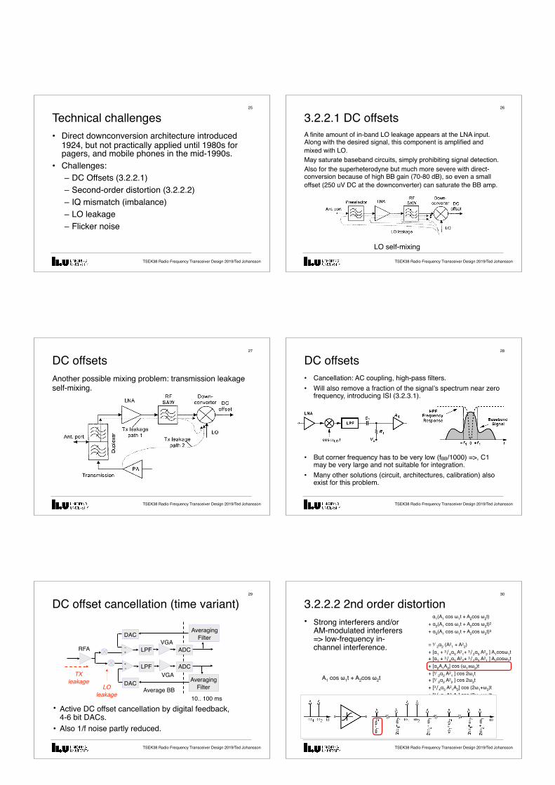
3.2.2.2 2nd order distortion�30
• Strong interferers and/or AM-modulated interferers => low-frequency in-channel interference.
A1 cos ω1t + A2cos ω2t
α1(A1 cos ω1t + A2cos ω2t)+ α2(A1 cos ω1t + A2cos ω2t)2 + α3(A1 cos ω1t + A2cos ω2t)3
= ⅟2α2 (A21 + A2
2)+ [α1 + 3∕4α3 A2
1+ 3∕2α3 A22 ] A1cosω1t
+ [α1 + 3∕4α3 A22+ 3∕2α3 A2
1 ] A2cosω2t+ [α2A1A2] cos (ω1±ω2)t+ [⅟2α2 A2
1 ] cos 2ω1t + [⅟2α2 A2
2 ] cos 2ω2t+ [3∕4α3 A2
1A2] cos (2ω1+ω2)t+ [3∕4α3 A2
2A1] cos (2ω2+ω1)t+ [3∕4α3 A2
1A2] cos (2ω1-ω2)t+ [3∕4α3 A2
2A1] cos (2ω2-ω1)t+ [⅟4 α3 A3
1 ] cos 3ω1t+ [⅟4 α3 A3
2 ] cos 3ω2t

TSEK38 Radio Frequency Transceiver Design 2019/Ted Johansson
IP2 considerations (partially 3.2.3.2)�31
• High IIP2 is needed in direct-conversion receivers.• 2nd order distortion by LNA and RFA easy to block
with the RF BPF and AC coupling cap.• => IIP2 RX mostly given by the IQ down-converters.
TSEK38 Radio Frequency Transceiver Design 2019/Ted Johansson
2nd order distortion�32
RF Filter
LNA RFALPF
LPF
ADC
ADC
In-band interference 2-tone model:
Low frequencyIM2 product before mixer not harmful,
easy to remove
IM2 takes effect in downconversion,
LPFs stop interferers,high mixer IP2 reduces
the problem
IM2RX ≈ IM2Mixer Homodyne RX needs very high IP2 of mixers
TSEK38 Radio Frequency Transceiver Design 2019/Ted Johansson
3.2.2.3 IQ mismatch (imbalance)�33
• High BB gain (80 dB)• I and Q separated on chip• Wide range of gain control in both BB channels=> Hard to keep I and Q perfectly symmetrical (gain and phase)
• Stepped gain control (3, 6, 9 dB) offers better accuracy than continuous gain control, but possibly DC-spikes during stepping.
• CDMA: <1 dB, <10° imbalance OK. • Other standards: maybe 2x higher requirements.
TSEK38 Radio Frequency Transceiver Design 2019/Ted Johansson
IQ mismatch (imbalance)�34
Complex envelope model for IQ downconversion:
sBB = (aI + jaQ) × (cosα-jsinα)~
IQ crosstalk caused bynoncoherent downconversion
Absolute phase imbalance
TSEK38 Radio Frequency Transceiver Design 2019/Ted Johansson
IQ mismatch (imbalance)�35
Also crosstalk but different effect on signal constellation
Complex envelope model for IQ downconversion:
~
(Also gain imbalance applies)
sBB = (aI + jaQ) × (cosθ/2+jsinθ/2)
Relative phase imbalance
TSEK38 Radio Frequency Transceiver Design 2019/Ted Johansson
QPSK simulation example: IQ crosstalk�36
Tx I
Tx Q
Rx Q
Rx I
Crosstalk for rotation α =16°
α = 16°
Skew
α =16°θ =5°
Received constellations
Rotation

TSEK38 Radio Frequency Transceiver Design 2019/Ted Johansson
3.2.2.4 LO leakage emission�37
• LO couples to the antenna through:(a) device capacitances between LO and RF ports of mixer and device capacitances or resistances between the output and input of the LNA.(b) the substrate to the input pad, especially because the LO employs large on-chip spiral inductors.
TSEK38 Radio Frequency Transceiver Design 2019/Ted Johansson
LO leakage emission�38
• Allowable emission level: -60 to -80 dBm• LO input level to mixer: -5 to 0 dBm• Reverse isolation to get < -80 dBm => > 85 dB• LO leakage can be minimized through symmetric
layout of the oscillator and the RF signal path.=> LO leakage arises primarily from random or deterministic asymmetries in the circuits and the LO waveform.
TSEK38 Radio Frequency Transceiver Design 2019/Ted Johansson
3.2.2.5 Flicker Noise�39
• Flicker noise or 1/f noise appears at low frequencies. It increases when frequency decreases.
• Flicker noise in MOSFET
• K is a process dependent constant, which is typically lower for PMOS devices than NMOS transistors.
Transistor width Gate length
TSEK38 Radio Frequency Transceiver Design 2019/Ted Johansson
Flicker Noise: corner frequency�40
• For CMOS devices, the 1/f noise corner falls in the range of tens or hundreds of MHz in today’s MOS technologies.
TSEK38 Radio Frequency Transceiver Design 2019/Ted Johansson
Flicker noise�41
• Since the signal is centered around zero frequency, it can be substantially corrupted by flicker noise.
• Fix: lower 1/f noise, NF optimization of RX chain.
TSEK38 Radio Frequency Transceiver Design 2019/Ted Johansson
3.2.3 Design consideration�42
• A lot of calculations• We will be coming back to this in lectures 6 & 7.

TSEK38 Radio Frequency Transceiver Design 2019/Ted Johansson
3.2.3.6 Direct-Conversion Transmitter�43
READ BOOK!
TSEK38 Radio Frequency Transceiver Design 2019/Ted Johansson
Frequency plan�44
• TX synthesizer: when integrated, it should avoid VCO reverse modulation, since 2nd harmonic of TX can pull VCO at twice fTX.
• Offset technique preferred.VCOLO f
mf )11( ±=
TSEK38 Radio Frequency Transceiver Design 2019/Ted Johansson
Summary�45
• Homodyne RX well suited for integration. • Challenged by DC offset, high demands on IP2,
1/f noise.• No image problem in RX.• Most of the IP2-requirements are given by the
down-conversion mixer,• Homodyne TX simple – one step – but
challenges by possible pulling of LO.www.liu.se