Embed Size (px)
Citation preview
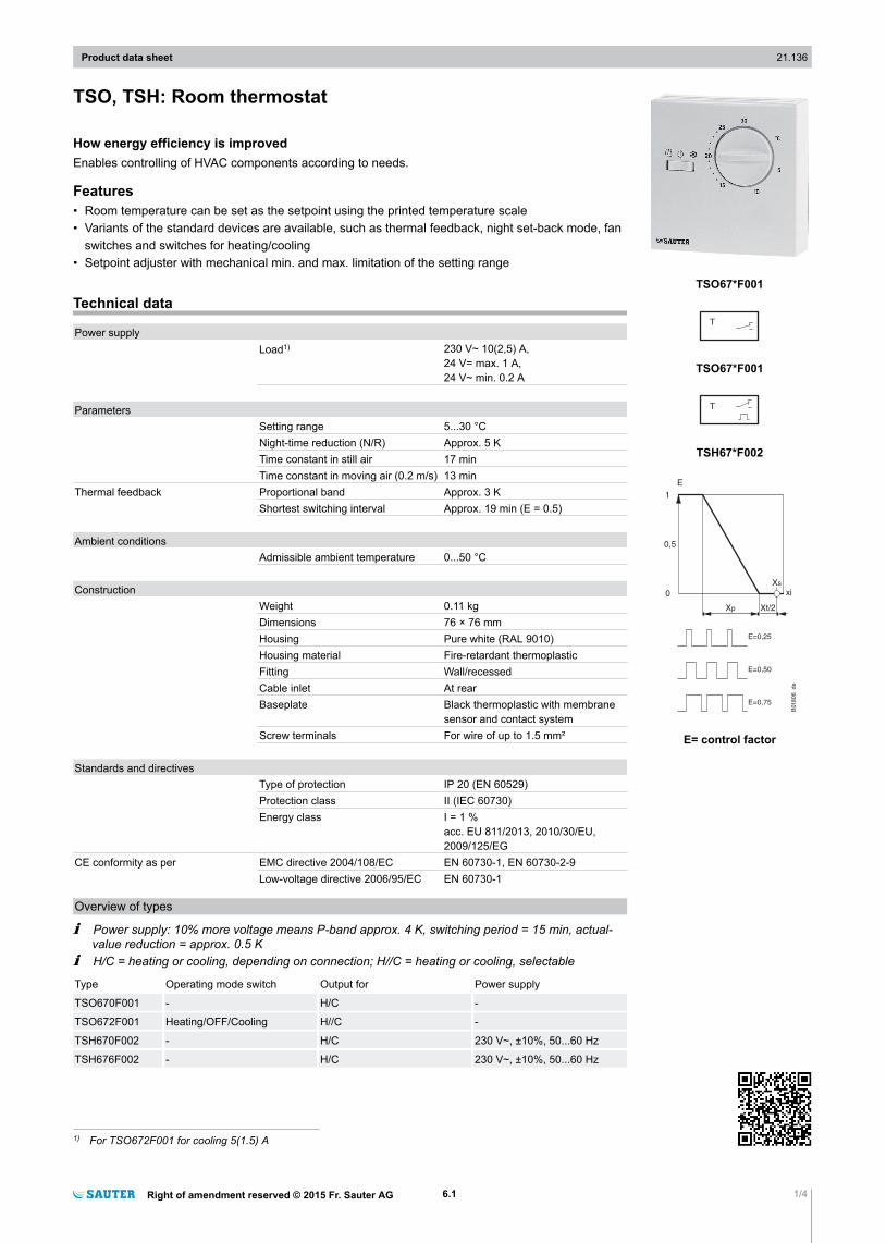
TSO, TSH: Room thermostat
How energy efficiency is improvedEnables controlling of HVAC components according to needs.
Features• Room temperature can be set as the setpoint using the printed temperature scale• Variants of the standard devices are available, such as thermal feedback, night set-back mode, fan
switches and switches for heating/cooling• Setpoint adjuster with mechanical min. and max. limitation of the setting range
Technical data
Power supplyLoad1) 230 V~ 10(2,5) A,
24 V= max. 1 A,24 V~ min. 0.2 A
ParametersSetting range 5...30 °CNight-time reduction (N/R) Approx. 5 KTime constant in still air 17 minTime constant in moving air (0.2 m/s) 13 min
Thermal feedback Proportional band Approx. 3 KShortest switching interval Approx. 19 min (E = 0.5)
Ambient conditionsAdmissible ambient temperature 0...50 °C
ConstructionWeight 0.11 kgDimensions 76 × 76 mmHousing Pure white (RAL 9010)Housing material Fire-retardant thermoplasticFitting Wall/recessedCable inlet At rearBaseplate Black thermoplastic with membrane
sensor and contact systemScrew terminals For wire of up to 1.5 mm²
Standards and directivesType of protection IP 20 (EN 60529)Protection class II (IEC 60730)Energy class I = 1 %
acc. EU 811/2013, 2010/30/EU,2009/125/EG
CE conformity as per EMC directive 2004/108/EC EN 60730-1, EN 60730-2-9Low-voltage directive 2006/95/EC EN 60730-1
Overview of types
/ Power supply: 10% more voltage means P-band approx. 4 K, switching period = 15 min, actual-value reduction = approx. 0.5 K
/ H/C = heating or cooling, depending on connection; H//C = heating or cooling, selectable
Type Operating mode switch Output for Power supply
TSO670F001 - H/C -
TSO672F001 Heating/OFF/Cooling H//C -
TSH670F002 - H/C 230 V~, ±10%, 50...60 Hz
TSH676F002 - H/C 230 V~, ±10%, 50...60 Hz
1) For TSO672F001 for cooling 5(1.5) A
Product data sheet 21.136
Right of amendment reserved © 2015 Fr. Sauter AG 6.1 1/4
TSO67*F001
TSO67*F001
TSH67*F002
1
0,5
0
Xp
xi
E=0,25
E=0,50
E=0,75
Xs
Xt/2
E
B01806_de
E= control factor
A TSO670F001, TSO672F001: switching difference 1.3 K without thermal feedback2)
A TSH670F002, TSH676F002: dynamic switching difference 0.5 K with thermal feedback3)
A TSH676F002: additional feature N/R (normal/reduced) for external clock
AccessoriesType Description
0362225001 Intermediate plate, pure white, for wall mounting on recessed junction box
0303124000 Recessed junction box
A 0303124000: only in combination with intermediate cover plate 0362225001
Description of operationA membrane sensor expands depending on the temperature and activates an electrical switch. Theoperating points of the controller are determined by the setpoint entered and the switching difference.
Intended useThis product is only suitable for the purpose intended by the manufacturer, as described in the “De-scription of operation” section.All related product regulations must also be adhered to. Changing or converting the product is not ad-missible.
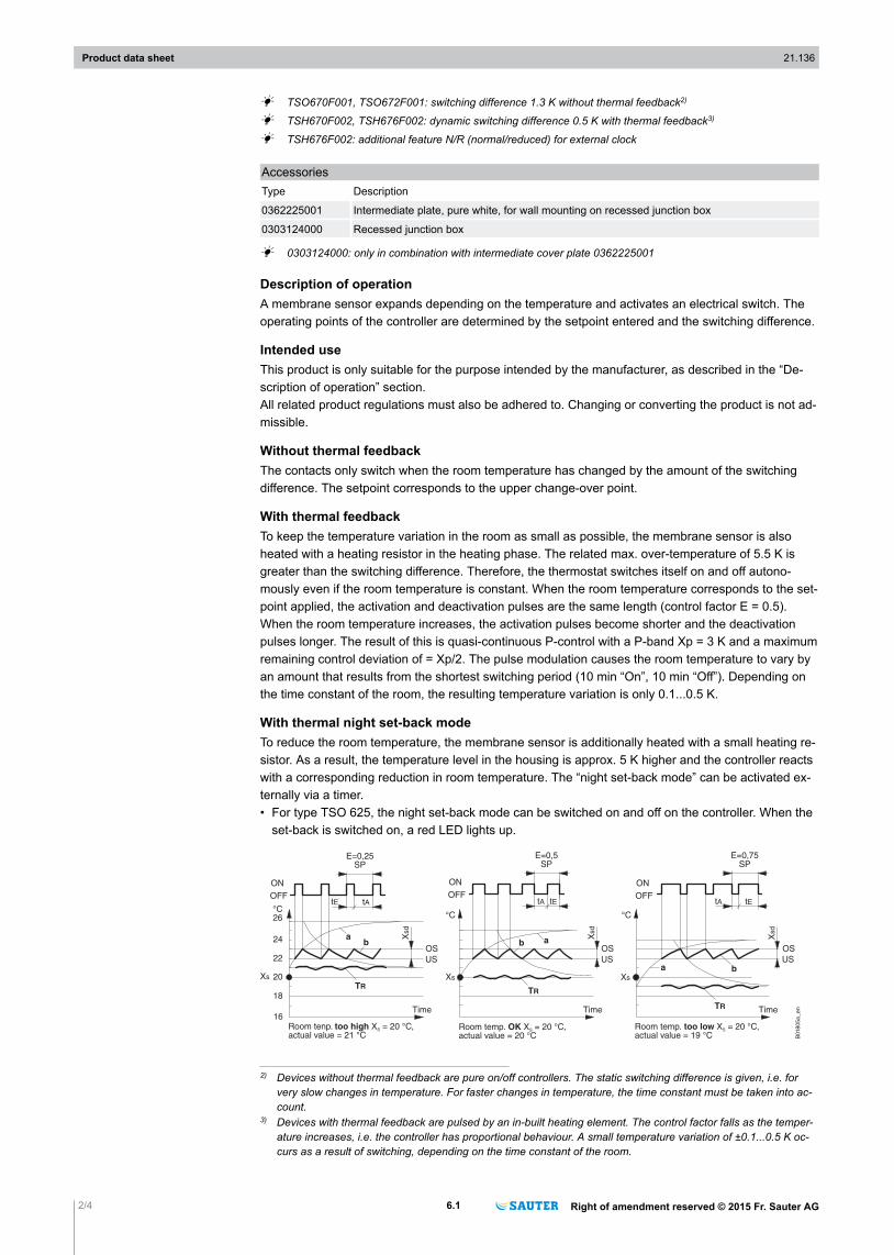
Without thermal feedbackThe contacts only switch when the room temperature has changed by the amount of the switchingdifference. The setpoint corresponds to the upper change-over point.
With thermal feedbackTo keep the temperature variation in the room as small as possible, the membrane sensor is alsoheated with a heating resistor in the heating phase. The related max. over-temperature of 5.5 K isgreater than the switching difference. Therefore, the thermostat switches itself on and off autono-mously even if the room temperature is constant. When the room temperature corresponds to the set-point applied, the activation and deactivation pulses are the same length (control factor E = 0.5).When the room temperature increases, the activation pulses become shorter and the deactivationpulses longer. The result of this is quasi-continuous P-control with a P-band Xp = 3 K and a maximumremaining control deviation of = Xp/2. The pulse modulation causes the room temperature to vary byan amount that results from the shortest switching period (10 min “On”, 10 min “Off”). Depending onthe time constant of the room, the resulting temperature variation is only 0.1...0.5 K.
With thermal night set-back modeTo reduce the room temperature, the membrane sensor is additionally heated with a small heating re-sistor. As a result, the temperature level in the housing is approx. 5 K higher and the controller reactswith a corresponding reduction in room temperature. The “night set-back mode” can be activated ex-ternally via a timer.• For type TSO 625, the night set-back mode can be switched on and off on the controller. When the
set-back is switched on, a red LED lights up.
tAtE
E=0,25SP
ON
OFF
°C26
24
22
20
18
Xs
ab
TR
Xsd
OS
US
Time
ab
Xsd
OS
US
tEtA
Time
E=0,5SP
TR
Xs
°C
Time
°C
Xsd
OS
US
tEtA
E=0,75SP
TR
a bXs
16
ON
OFF
ON
OFF
B01805a_en
Room tenp. X = 20 °C,actual value = 21 °C
too high S Room temp. X = 20 °C,actual value = 19 °C
too low SRoom temp. X = 20 °C,actual value = 20 °C
OK S
2) Devices without thermal feedback are pure on/off controllers. The static switching difference is given, i.e. forvery slow changes in temperature. For faster changes in temperature, the time constant must be taken into ac-count.
3) Devices with thermal feedback are pulsed by an in-built heating element. The control factor falls as the temper-ature increases, i.e. the controller has proportional behaviour. A small temperature variation of ±0.1...0.5 K oc-curs as a result of switching, depending on the time constant of the room.
Product data sheet 21.136
2/4 6.1 Right of amendment reserved © 2015 Fr. Sauter AG
KeyXS Setpoint tE Operating time
Xp Proportional band tA Duration of 'off' time
XSd Switching difference SP Switching period (tE + tA)
TR Room temperature E Control factor (tE/SP)
OS Upper change-over point a Transient response of therm. feedbackUS Lower change-over point b Temperature at membrane sensor
Engineering and fitting notesThe specified voltage tolerances are necessary because the output of the feedback heating resistor issignificantly dependent on it. 10% excess voltage results in: 20% more power, P-band 4 K, switchingperiod 15 min instead of 19 min, reduction in room temperature 0.5 K.
DisposalWhen disposing of the product, observe the currently applicable local laws.More information on materials can be found in the Declaration on materials and the environment forthis product.
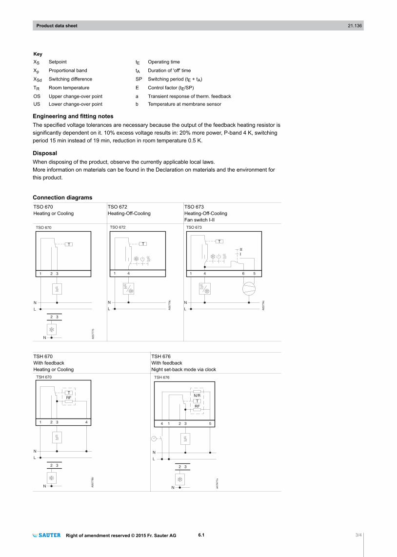
Connection diagramsTSO 670Heating or Cooling
TSO 672Heating-Off-Cooling
TSO 673Heating-Off-CoolingFan switch I-II
T
1 3
N
L
A0
57
77
b
2
32
N
TSO 670
T
1 4
N
L A05779c
TSO 672
T
1 4 6 5
N
L A05774c
TSO 673
TSH 670With feedbackHeating or Cooling
TSH 676With feedbackNight set-back mode via clock
T
1 3
N
L
A0
57
78
b
2
32
N
RF
4
TSH 670
T
1 3
N
L
A0
78
77
a
2
32
N
RF
54
N/R
TSH 676
Product data sheet 21.136
Right of amendment reserved © 2015 Fr. Sauter AG 6.1 3/4
RF Thermal feedbackN/R Normal/Reduced (night set-back mode)
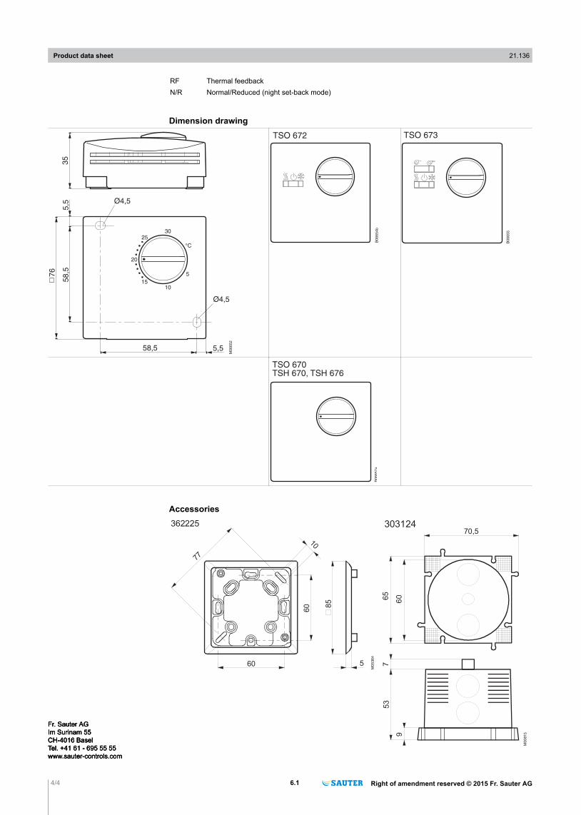
Dimension drawing
35
58,5
58,576
5,5
5,5
Ø4,5
Ø4,5
M06652
20
25
1015
5
30
°C
B0
66
54
b
TSO 672
B0
66
55
TSO 673
B0
66
57
a
TSO 670TSH 670, TSH 676
Accessories
60
60
M0
536
4
85
77
10
5
362225
Product data sheet 21.136
4/4 6.1 Right of amendment reserved © 2015 Fr. Sauter AG
Fr. Sauter AGIm Surinam 55CH-4016 BaselTel. +41 61 - 695 55 55www.sauter-controls.com
Fr. Sauter AGIm Surinam 55CH-4016 BaselTel. +41 61 - 695 55 55www.sauter-controls.com
Fr. Sauter AGIm Surinam 55CH-4016 BaselTel. +41 61 - 695 55 55www.sauter-controls.com