Embed Size (px)
Citation preview

Rev.D 05/10/2017
Tsunami2 and Econami Digital Sound Decoder
Installation Guide

Contents All Aboard! ............................................................................................................................... 3
Overview ...................................................................................................................................... 3
Pre-Installation Considerations ................................................................................................... 4
Installation ................................................................................................................................ 6
Step 1. Test the Motor Stall Current ........................................................................................... 6
Step 2. Plan the Installation ........................................................................................................ 7
Step 3. Isolate Motor and Lights from the Frame ....................................................................... 9
Step 4. Modify the Tender or Body Shell .................................................................................. 10
Step 5. Mount the Speaker ....................................................................................................... 12
Step 6. Install and Wire the Decoder ........................................................................................ 13
Step 7. Test the Istallation ........................................................................................................ 16
Wiring Diagrams .....................................................................................................................17
TSU-1100/ECO-100 .................................................................................................................. 17
TSU-2200/ECO-200 .................................................................................................................. 18
TSU-21PNEM/ECO-21PNEM ................................................................................................... 19
TSU-PNP/ECO-PNP ................................................................................................................. 20
TSU-4400/ECO-400 .................................................................................................................. 21
Notice The information in this document is subject to change without notice. SoundTraxx (Throttle Up! Corp.) shall not be liable for technical or editorial errors or omissions contained herein, nor for incidental or consequential damage resulting from the furnishing, performance or use of this material. This document contains information protected by copyright. No part of this document may be photocopied or reproduced in any form without the prior written consent of Throttle Up! Corp. Product names mentioned herein may be trademarks and/or registered trademarks of their respective companies. SoundTraxx, Tsunami2, Econami, Tsunami, SoundTraxx DCC, Dynamic Digital Exhaust, Auto-Exhaust, Hyperlight, Hyperdrive2, SoundCar, and Intelligent Consisting are trademarks of Throttle Up! Corp.

All Aboard!
Tsunami2 and Econami Installation Guide 3
All Aboard!
Overview Congratulations on the purchase of your Tsunami2 or Econami Digital Sound Decoder! Properly installed, this decoder will provide high-quality sound, realistic lighting effects, and superior motor control. This installation guide will give you step-by-step instructions to successfully install the following Tsunami2 and Econami formats for steam, diesel, or electric locomotives:
Tsunami2 Econami
TSU-1100 ECO-100
TSU-2200 ECO-200
TSU-21PNEM ECO-21PNEM
TSU-PNP ECO-PNP
TSU-4400 ECO-400
Though each decoder is tested thoroughly before shipping, we cannot control the correctness or quality of a given installation. It is imperative that you follow the directions, and never remove the protective heat-shrink from the decoder; there are no adjustments that can be made to the hardware and this will void your warranty. The difficulty of an installation depends principally on the modeler, and may be more or less challenging according to any given circumstance. However, an installer should generally have basic modeling skills, be comfortable disassembling a model, and be able to identify wires, such as power pickups and motor leads. Note: In the event that you damage the decoder during installation, our warranty policy is outlined in the User’s Guide and on our website. It includes information about returning the decoder to SoundTraxx for repair or replacement. Further documentation regarding steam, diesel, or electric versions of your decoder:
If you’re new to DCC and sound, refer to the Quick Start Guides for default operation and programming highlights.
Refer to the User’s Guides for in-depth instructions regarding operating and programming your digital sound decoder.
Refer to the Technical References for details regarding each CV included in your Digital Sound Decoder.
Refer to the Sound Selection References for a quick guide of CV values to adjust sound effects in each version.
Refer to the SoundTraxx Guide to Successful Soldering for soldering tips and recommendations.
To download all user documentation, visit www.soundtraxx.com/manuals.php.

All Aboard!
Tsunami2 and Econami Installation Guide 4
Pre-Installation Considerations Carefully read the instructions that are printed on the decoder’s packaging. Then, finish reading this installation guide. While installing the decoder, keep these precautions in mind:
Handle the decoder carefully in a static-free environment. To discharge static electricity before handling the decoder, touch a water pipe or another grounded metal surface.
Never remove the decoder’s protective shrink tubing; this voids your warranty.
Never make connections to the decoder while it is receiving power.
Make sure all electrical connections are insulated. Avoid using electrical tape; it tends to unwrap over time. We recommend using heat-shrink tubing instead.
Never allow the decoder leads to come in contact with any DCC track wiring not specifically designed for that purpose.
Never allow speaker or motor outputs to be shorted together.
Do not exceed the output ratings for which the decoder is designed.
Do not choose a locomotive with a stall current exceeding the decoder’s rating; always test the stall current of your locomotive before installing the decoder.
If possible, mount the decoder in an area with some airflow to provide ventilation for the decoder.
Mount the decoder away from other heat sources (such as the motor or lamps) to avoid overheating.
Always use a proper speaker enclosure (baffle) and select the largest speaker possible.
Choose an appropriately rated speaker.
Take your time and have fun!
Testing the Decoder Prior to Installation In rare cases, damage received during shipping or improper handling can cause a decoder to fail prematurely. We recommend that you test all Digital Sound Decoders and accessories within the item’s warranty period prior to beginning the installation. Proper bench testing of decoders can save countless hours of headache and frustration if problems are discovered after the installation process has begun Testing the decoder on your workbench can be accomplished by connecting the wires/pads from the DSD to a surplus motor, 8 ohm speaker and 12 volt lamps. Refer to the appropriate wiring diagram for your decoder when making these connections. Also ensure that the wire connections are mechanically sound and well insulated to prevent damage to the decoder or accessories during testing. When the appropriate connections have been made, test the motor by running it in both forward and reverse directions. Test each lighting output by turning on the corresponding function key. Lastly, check the audio output of the DSD by blowing the horn or whistle, ringing the bell and listening for changes in prime mover notch, exhaust chuff or traction motor whine. If you should discover any issues during this test, please contact our Customer Support department for assistance. Note: Neither Tsunami2 nor Econami require a programming track booster.

All Aboard!
Tsunami2 and Econami Installation Guide 5
Tools and Materials You Will Need In addition to the common hand tools found on most modeler’s workbenches, you should have the following at your disposal:
Low-wattage soldering iron
Rosin-core solder and electronics safe flux
Hobby knife
Miniature screwdriver set
Diagonal wire cutters
Handheld rotary tool
Multimeter
Double-sided foam tape
Heat-shrink tubing
Silicone RTV
Drill bit assortment We have a variety of accessories to aid your installation. For more information about our full line of installation accessories, visit www.soundtraxx.com/access/index.php. Miniature Speakers, Baffles, and Gaskets: We have a variety of miniature speakers, baffles, and gasket kits for use with our digital sound decoders; choose the largest speaker the installation will allow.
Wiring Aids Micro-connectors can be used to facilitate easy separation of components. NMRA-Compatible Connectors are used for converting universal-style decoders to a “plug-and-play” format. DBX-9000 Wiring Kit facilitates easy separation of the locomotive and tender. Super-flexible wire is ideal for working in tight spaces.
DCC Accessories The CurrentKeeper helps maintain decoder performance during momentary power losses. Microbulbs and LEDs let you take advantage of our Hyperlight lighting effects.

Installation
Tsunami2 and Econami Installation Guide 6
Installation
Step 1. Test the Motor Stall Current Test the locomotive’s stall current to ensure that it is compatible with the decoder that you have chosen:
1. Place the locomotive on a section of track powered by a conventional DC powerpack set to the same track voltage as your command station (typically 12-14 volts).
2. Referring to Figure 1, connect a DC ammeter in series with one of the track feeders. If your powerpack has built-in meters, you may use them for this purpose.
Figure 1: Testing the Locomotive’s Motor Stall Current
3. Immobilize the locomotive by holding it to the track, and turn on the powerpack.
4. Firmly press down on the locomotive or hold the motor’s flywheel to stop it from spinning.
5. Ensure the powerpack voltage remains the same to receive an accurate measurement.
6. Measure the current the locomotive is drawing while the motor is stalled; this is the stall current.
7. Ensure the motor stall current is less than the decoder’s rated capacity.

Installation
Tsunami2 and Econami Installation Guide 7
Step 2. Plan the Installation The sound quality you will receive from your Digital Sound Decoder depends upon your speaker selection, the way you install the speaker, and the location of the decoder within the model. Consider the following as you plan your sound installation:
Provide ventilation for the decoder if possible.
Mount the decoder away from other heat sources (such as the motor or lamps) to reduce the chance of overheating.
Always provide a proper enclosure (baffle) for the speaker. Lack of a speaker baffle will cause poor sound quality.
Speaker Considerations Select the largest speaker that your model permits to achieve higher volume and better quality low-frequency response for a more realistic sounds. We offer a range of speakers that you can use with your model. Note: Be sure that your speaker is rated to match the audio amplifier of your decoder; failure to do so could cause damage to your speaker. Check the packaging and our website for ratings for each decoder format. Note: If a single large speaker isn’t an option, you may be able to use two or three smaller speakers to improve the frequency response. For details, refer to “Wiring Multiple Speakers” within Step 6. Install and Wire the Decoder (Pg. 13).
Mini Cube Speakers 28 mm (1”) Round Speaker 16 x 35mm Oval Speaker
Speaker Enclosures A speaker enclosure (baffle) should be used to allow air pressure to build up and amplify sound. The enclosure should fit the speaker. The pressure building within an enclosure that is too small for the speaker will compromise certain frequencies and muffle the sound response. As a guideline, enclosures for speakers measuring less than 3” in diameter should be built using the cubic relationship between height, length and width. For example, a 1” speaker should be paired with a 1” x 1” x 1” enclosure. Note: Employing a proper speaker enclosure cannot be emphasized enough; the absence of an effective enclosure is almost always the cause of poor sound quality.
Speaker enclosures should also be:
Fixed with stiff walls to prevent vibrations and buzzing
Installed flush with the speaker dimensions to create an airtight space for the speaker cone to build pressure and produce a strong sound response
We offer various snap-together baffle kits like the one shown below.
SoundTraxx Speaker Baffle Kit

Installation
Tsunami2 and Econami Installation Guide 8
Steam Locomotive Considerations Sound quality is greatly affected by speaker placement, which depends on the size and type of locomotive. The speaker will produce higher quality sound when fixed within an airtight enclosure with the front of the speaker facing open air. Most steam engines have a tender that can be used as an enclosure. You can orient the speaker face up toward the coalbunker or face down toward the floor – both offer quality sound. In small tenders, the speaker can be mounted in the coalbunker area with higher walls covering the speaker magnet. If this isn’t possible, you may need to get creative and install the speaker in the boiler or smokestack. We also offer an assortment of baffle kits, or you can create enclosures from sheet styrene, basswood, or cardboard. If you’re in a pinch, try using a plastic bottle lid, a 35mm film canister, or the paperboard core from a roll of paper towels. Figure 2 shows a typical sound installation for a steam locomotive with the speaker pointing up through the coal load. The tender shell acts as a baffle for the speaker. To allow the sound to escape, the plastic coal load can be perforated with small holes.
Figure 2: Steam Sound Installation
Diesel Locomotive Considerations When planning a diesel installation, we recommend providing additional airflow if possible. When possible avoid mounting the decoder above the motor; the motor will raise the decoder’s temperature during operation. Figure 3 shows a typical diesel installation where the speaker has been mounted in the fuel tank with the decoder under the fan grilles. Opening the fan grilles and drilling a number of small holes through the underside of the frame will create some airflow, and the fuel tank will act as a baffle for quality sound.
Figure 3: Diesel Sound Installation

Installation
Tsunami2 and Econami Installation Guide 9
Step 3. Isolate Motor and Lights from the Frame Note: If you have a DCC-ready model with an NMRA 8-pin connector, NMRA 9-Pin “JST” connector, or 21-Pin “NEM” connector, proceed to page 15. To ensure only the decoder’s motor outputs are driving the two motor connections, isolate the motor connections from the locomotive frame, left rail, and right rail pickups. Many locomotives are “DCC-ready,” and this step may not be necessary, though it varies depending upon the manufacturer. Under Step 6. Install and Wire the Decoder, refer to “Installing into DCC-Ready Locomotives” for more information regarding DCC-ready installations. Note: Failure to properly isolate the motor may damage the decoder and we recommend always practicing this step during the installation process. To verify that the motor terminals are isolated from the chassis and rail pickups, refer to the following procedure:
1. Make sure to have an ohmmeter or continuity tester that you can use to confirm that each motor terminal is isolated.
2. Remove the body shell from the locomotive (and the tender shell for steam installations).
3. Examine the locomotive wiring and locate each wire and where each wire is connected; identify the power pickups for the left and right rails and the positive (+) and negative (−) motor connections.
Note: The positive motor connection is connected to the right rail (engineer side) power pickup.
Figure 4: Conventional DC Power Pickups
4. Disconnect all wires that lead to motor
terminals.
Note: Some motor connections are made by a spring contacting the “live” chassis. In this instance, remove or modify the spring contact. Be aware that the motor and frame are permitted to make contact when the body is reinstalled in some locomotives.
5. Set the multimeter to continuity or ohmmeter, and touch both meter probes together. Ensure it reads 0 (short circuit) to verify the meter is functioning correctly.
6. Touch one probe to a motor terminal.
7. Touch the other probe to the locomotive’s frame, then to the power pickup wire for the left rail, then to the power pickup wire for the right rail and ensure the meter indicates an open circuit.
8. To complete the test, remove the probe from the terminal that has already been tested and touch it to the other motor terminal. Then, ensure the meter indicates an open circuit by performing the same test with the other probe: touch it to the frame, the left rail pickup, and then the right rail pickup.
9. Disconnect all lighting wires.
10. Using the ohmmeter (or continuity tester), verify each lamp lead is isolated from the locomotive’s frame, the left rail pickup, and the right rail pickup.

Installation
Tsunami2 and Econami Installation Guide 10
Step 4. Modify the Tender or Body Shell A certain amount of “bodywork” may be necessary to accommodate the speaker and sound system. This typically includes removing weights, mounting brackets, and internal bracing, as well as modifying other structural features.
Steam Modification Installing a decoder in a steam locomotive often involves modifying the tender and tender floor.
Heighten Low Tender Sidewalls On tenders with low sidewalls, the speaker will often be mounted face up in the coalbunker to provide adequate clearance for the sound system fixed to the tender floor. To heighten the sidewalls, add wooden retaining boards:
1. On the tender deck, trace around the speaker.
2. With a jeweler’s saw, cut an opening around the outline.
3. File and remove all sharp edges and burrs.
4. Contour a piece of fine mesh or foam and cover the coal load to disguise the speaker.
Note: Tenders with flat decks across the coalbunker are less difficult to modify.
Styrene Subdeck Speaker Mount Plastic tenders often have a molded coal load already in place. The inside surface is contoured to match the coal load and does not provide a flat mounting surface. A subdeck can be fabricated from 0.060” styrene to fit tightly against the tender sides below the coal load:
1. Cut a large circular opening appropriate for the speaker’s diameter into the styrene sheet.
2. Glue the subdeck to the inside of the tender shell.
3. Using a No. 60 drill bit, drill through the coal load several times at random angles between the coal “nuggets” to allow sound to escape.
Tenders with Exposed Coal Slope Sheets More prototypical tenders have fuel bunkers that extend to the tender floor. Consider tender size before mounting the speaker:
For larger tenders, the speaker should be mounted on the tender floor.
For smaller tenders, the slope sheet and interior walls will interfere with the speaker and the sound system. It will usually be necessary to remove and replace them with sheet brass or styrene to create a flat-decked tender.
Figure 5: For some models, you may have to heighten sidewalls to provide
clearance for the sound system.
Figure 6: For models with a molded coal load, create a subdeck to
provide a flat mounting surface.
Figure 7: If necessary, replace the slope sheet and inside walls with
sheet brass or styrene to accommodate the sound system.

Installation
Tsunami2 and Econami Installation Guide 11
Modify the Tender Floor Speakers can be located on the tender floor in many instances. Consider the following when mounting the speaker to the tender floor:
1. Determine the exact speaker location within the tender and verify that there is clearance between the tender body and speaker magnet.
2. In the pattern shown in Figure 8, drill 10-15 holes to provide an opening for the sound to escape; each hole should measure roughly 1/4” in diameter.
3. Take care not to alter the tender underbody detail and drill towards the center of the circle, only within the specified area.
4. Once you have drilled the holes, file all burrs and uneven edges and ensure no solder joints, screw bosses, or mounting studs obstruct the speaker mount; the tender floor should be smooth and flush against the surface of the speaker.
Diesel Modification Consider the following for diesel models:
You may need to remove weight from the fuel tank or replace the model’s fan grilles with some open-grille detail parts.
You will need to fashion a mounting plate for the speaker and seal it well.
If you place the speaker under open fan grilles, consider using a separate speaker baffle rather than the body, as it may be difficult to seal the chassis well enough to achieve the desired results.
Figure 9 shows some common diesel modifications:
Figure 9: Common Diesel Body Modifications
Figure 8: For speakers mounted on the tender floor, drill holes below the speaker
to allow the sound to escape.

Installation
Tsunami2 and Econami Installation Guide 12
Step 5. Mount the Speaker After you’ve modified the model appropriately, arrange the speaker components and secure them in place.
Mount the Speaker Once bodywork is complete and the speaker has been fitted in place, it must be secured tightly to the enclosure. For the best sound, the seal around the speaker’s edge should be airtight. We offer several speaker gasket kits for easy and neat speaker mounting. You may also hold the speaker in place using a silicone RTV to provide a seal and allow the speaker to be removed in the future. Using epoxy or other hard glues does not allow this. Be careful that you don’t get any RTV onto the speaker cone, as this will cause sound distortion.
Speaker Gaskets We recommend using a speaker gasket to secure the speaker into place. Please visit our website for a full list of speakers, speaker enclosures, and speaker gaskets.
Installing Speakers with Gaskets Consider the following as a guide for mounting the speaker with a gasket:
For each side of the gasket, peel back the paper backing with a pair of tweezers or a hobby knife and expose the adhesive.
Fix the gasket to the speaker, and fix the speaker to the desired surface.
Take care not to fix the gasket to the speaker cone.
Figure 10: SoundTraxx Speaker Gasket Installation

Installation
Tsunami2 and Econami Installation Guide 13
Step 6. Install and Wire the Decoder
Track Connections 1. Connect the decoder’s red wire to the
right rail power pickup.
2. Connect the decoder’s black wire to the left rail power pickup.
Motor Connections 1. Connect the decoder’s orange wire to
the motor’s positive (+) terminal.
2. Connect the decoder’s gray wire to the motor’s negative (−) terminal.
Figure 11: Track and Motor Connections
Speaker Connections 1. Connect the decoder’s purple speaker
(+) wire to one of the speaker terminals.
2. Connect the decoder’s purple speaker (−) wire to the other speaker terminal.
Figure 12: Soldering to Speaker Terminal Connections
Wiring Multiple Speakers Refer to Figure 13 when wiring multiple speakers. Be aware of the speaker polarity. If a speaker is wired backwards relative to another speaker, the two speakers will release opposing sound waves and will be unable to reproduce sound effectively. This will result in diminished volume levels. If the speaker does not indicate polarity on its terminal, wire terminals to corresponding terminals, i.e., wire left terminals to left terminals, and right terminals to right terminals, respectively. Note: The polarity of the speaker terminals is only important when using multiple speakers (see above). If you have installed multiple speakers, make sure they are phased properly, i.e., positive lead to positive lead and negative lead to negative lead of each speaker. On smaller speakers, solder the wires to the outside edges of the solder pads. Note: Do not use SoundTraxx Digital Sound Decoders with speakers with a total impedance less than 8 ohms. Doing so may result in erratic operation, or even cause component failure.
Figure 13: Multi-Speaker Wiring Note: Values assume 8-ohm speaker impedance.

Installation
Tsunami2 and Econami Installation Guide 14
Lighting Connections Up to 6 lighting outputs are connected by way of the Function Common (Blue wire or “+” pad) and the Headlight, Backup Light, FX3, FX4, FX5, and FX6 function wires (or corresponding pads) found on the decoder. Because of the wide variety of lighting used by model manufacturers, it’s important to know the voltage rating of your locomotive’s lamps or LEDs. Connecting lighting rated for less than 12 volts (such as 1.5V microbulbs, 3.3V LEDs, 3V lamps or 6V lamps) directly to the decoder can cause damage to the on-board circuitry as well as damage to the lamps or LEDs themselves. Refer to the information below for proper wiring of the most common types of lighting installed in locomotives.
Wire the decoder to 12V Lamps Refer to Figure 14 to use 12V Lamps. Wire the 12V lamps directly to the headlight and backup light. The 12V lamps may also be wired directly to FX3-FX6 lighting outputs.
Figure 17: Wiring 12V Lamps
Figure 14: Wiring to 12V Lamp
Wire the decoder to 1.5V Microbulbs To use 1.5V microbulbs, refer to Figure 15. Wire a small current-limiting resistor with each lamp to prevent lights from burning out. A separate resistor must be used for each bulb even if you connect it to the same output. We recommend using a 560-ohm, 1/4-watt resistor with each bulb. However, you may need to adjust the resistance to achieve the appropriate brightness. This is determined by the output voltage for your command station. Lower resistance will increase the lamp brightness.
Figure 15: Wiring to 1.5V Microbulbs
Note: Econami PNP and Tsunami2 PNP format decoders are equipped with a 1.5 Volt regulated output. Refer to the wiring diagrams on page 21 for more information.
Wire the decoder to LEDs SoundTraxx decoders support the use of LEDs wired in-series using 1K (1000) OHM, 1/4 watt resistors. Unlike incandescent bulbs, LEDs are sensitive to polarity:
The negative (−) LED cathode (shorter lead) connects to the decoder’s corresponding lighting output.
The positive (+) LED anode (longer lead) connects to the decoder’s blue Function Common wire.
Figure 16: Wiring 3.3V LEDs

Installation
Tsunami2 and Econami Installation Guide 15
DCC-Ready Locomotive Installations NMRA 8-Pin Sockets If your locomotive is wired with an NMRA-compatible 8-pin socket, you may solder a mating connector to the decoder’s wire harness to allow simplified plug-in installation for all wiring excluding speaker connections. We offer a package of four connectors (P.N. 810123) that meet NMRA specifications. Wire the connector according to Figure 17.
Figure 17: NMRA 8-Pin Wiring Diagram
Note: Some models equipped with 8-pin sockets may not be compatible with the NMRA standard. If you are unsure of the wiring standard used in your 8-pin socket equipped model, please refer to the Technical Note entitled “Testing NMRA 8-Pin Sockets” found on our website.
NMRA 9-Pin “JST” Plug Many models are being equipped with this DCC “Quick-Plug” connector for easy installation of TSU-2200 or ECO-200 decoders. The following procedure can be used when installing these decoders: 1. Remove the factory supplied 9-pin
dummy plug from the model and ensure that the NMRA 8-Pin dummy plug (if equipped) has been removed as well.
2. Using a hobby knife, remove a small amount of shrink wrap from the decoder around the 9-pin plug.
3. Pull gently with even force applied to all 9 wires to remove the SoundTraxx wire harness from the decoder.
4. Plug the decoder into the NMRA 9-pin “JST” wire harness located in the model.
5. Refer to the wiring diagram for TSU-2200 and ECO-200 decoders for connection of the speaker and any additional lighting functions.
Figure 18: NMRA 9-Pin “JST” Wiring Diagram
21-Pin NEM Connector Interface Figure 19: 21-Pin NEM Wiring Diagram Please refer to page 19 for more information about this interface and SoundTraxx 21-Pin NEM decoders. Note: SoundTraxx 21-Pin NEM decoders are designed for use with factory supplied motherboards which support the NEM specifications. Our decoders are not intended for use with 21-Pin NMRA standard sockets.

Installation
Tsunami2 and Econami Installation Guide 16
Step 7. Test the Installation At this point, you should be ready for the test track. We recommend your test track be equipped with a fast-blow fuse appropriately rated for your decoder (1-amp decoder = 1-amp fuse). Test the installation according to the following:
1. Place the locomotive on the track and turn the power on.
2. Set your controller to locomotive address 3.
3. Verify that your locomotive will move in both directions and turn the headlight and backup light on and off with the corresponding function keys (F0 forward and reverse).
4. For steam decoders, verify the airpump is running automatically in the background.
5. For diesel decoders, verify the engine RPM is at a steady idle. If your locomotive responds to direction changes incorrectly, the motor connections have been reversed. Refer to the following to correct them:
1. Turn the power off.
2. Reconnect the decoder’s orange wire to the motor terminal previously connected to the decoder’s gray wire, and reconnect the decoder’s gray wire to the motor terminal previously connected to the decoder’s orange wire.
3. Place your locomotive back on the test track and verify correct movement in the forward and reverse directions.
After successfully testing your installation, secure the decoder and all loose wires with Kapton tape or double sided foam tape to prevent interference with the locomotive’s shell, motor or other drive-line components. Trim, insulate the ends and secure all unused FX lighting outputs to prevent accidental contact with other components during reassembly.

Wiring Diagrams
Tsunami2 and Econami Installation Guide 17
TSU-1100/ECO-100 The TSU-1100 and ECO-100 are “universal” style decoders for hard-wired installations in many W scale and small HO scale models. Wires are color-coded according to the NMRA Standard (where applicable):
Power, Motor, Headlight, and Backup Light Wires:
Black: Left Rail Pickup (-)
Gray: Motor (-)
Yellow: Backup Light
White: Headlight
Green/Yellow Stripe: Ground
Blue: Function Common (12V)
Orange: Motor (+)
Red: Right Rail Pickup (+)
Speaker and FX Wires:
Purple: Speaker (+)
Purple: Speaker (-)
Green: FX3
Brown: FX4
CurrentKeeper Installation The TSU-1100 and ECO-100 both include an optional 220µF, 25V capacitor or may be used with a SoundTraxx CurrentKeeper to maintain performance during momentary power losses. To install a CurrentKeeper, remove the connector and trim the blue and black wires to about 3”. Strip and tin the ends of the CurrentKeeper’s wires, as well as the decoder’s blue (Function Common) and green/yellow stripe (Ground) wires. Slide a piece of heat-shrink tubing over each of the CurrentKeeper’s wires. Solder the blue CurrentKeeper wire to the blue decoder wire, and the black CurrentKeeper wire to the decoder’s green/yellow stripe wire. Slide the pieces of heat-shrink tubing over the connections and heat to insulate.
Figure 20: TSU-1100/ECO-100 Wiring Diagram
Wiring Diagrams
Tsunami2 and Econami Installation Guide 18
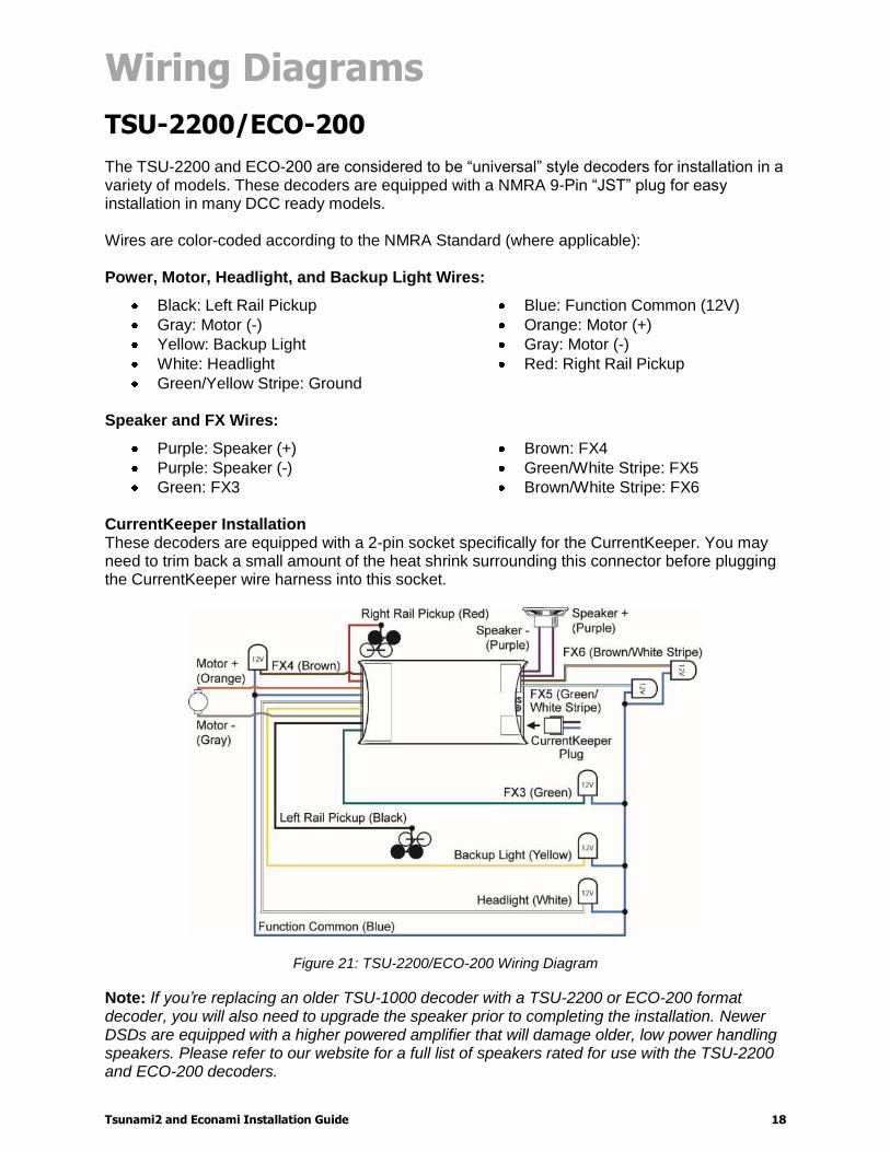
TSU-2200/ECO-200 The TSU-2200 and ECO-200 are considered to be “universal” style decoders for installation in a variety of models. These decoders are equipped with a NMRA 9-Pin “JST” plug for easy installation in many DCC ready models. Wires are color-coded according to the NMRA Standard (where applicable): Power, Motor, Headlight, and Backup Light Wires:
Black: Left Rail Pickup
Gray: Motor (-)
Yellow: Backup Light
White: Headlight
Green/Yellow Stripe: Ground
Blue: Function Common (12V)
Orange: Motor (+)
Gray: Motor (-)
Red: Right Rail Pickup
Speaker and FX Wires:
Purple: Speaker (+)
Purple: Speaker (-)
Green: FX3
Brown: FX4
Green/White Stripe: FX5
Brown/White Stripe: FX6 CurrentKeeper Installation These decoders are equipped with a 2-pin socket specifically for the CurrentKeeper. You may need to trim back a small amount of the heat shrink surrounding this connector before plugging the CurrentKeeper wire harness into this socket.
Figure 21: TSU-2200/ECO-200 Wiring Diagram
Note: If you’re replacing an older TSU-1000 decoder with a TSU-2200 or ECO-200 format decoder, you will also need to upgrade the speaker prior to completing the installation. Newer DSDs are equipped with a higher powered amplifier that will damage older, low power handling speakers. Please refer to our website for a full list of speakers rated for use with the TSU-2200 and ECO-200 decoders.

Wiring Diagrams
Tsunami2 and Econami Installation Guide 19
TSU-21PNEM/ECO-21PNEM The TSU-21PNEM and the ECO-21PNEM have a 21-pin, dual-row, bottom-entry connector arranged according to the NEM Standard. Orient the decoder so that Pin 1 on the factory-installed board lines up with the appropriate connector on the decoder, which is indicated by the white dot on top of the decoder. Plug the decoder into the factory-installed board. Solder or plug in the purple speaker wires to the appropriate location on the factory-installed board.
CurrentKeeper Installation In most cases, a CurrentKeeper may be soldered to the locomotive's factory-installed board to help maintain performance during momentary power interruptions. Please contact our Customer Support at (970) 259-0690 or [email protected] for assistance with determining the correct soldering locations.
Figure 22: TSU-21PNEM/ECO-21PNEM Wiring Diagram
Wiring Diagrams
Tsunami2 and Econami Installation Guide 20
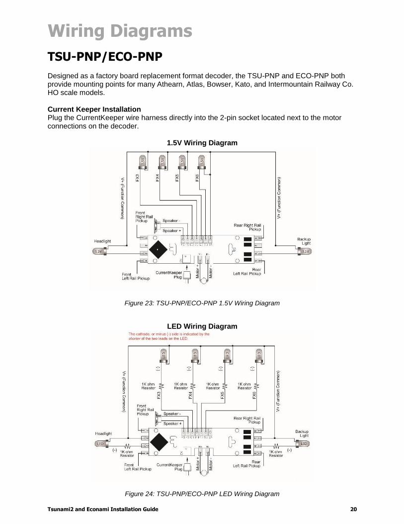
TSU-PNP/ECO-PNP Designed as a factory board replacement format decoder, the TSU-PNP and ECO-PNP both provide mounting points for many Athearn, Atlas, Bowser, Kato, and Intermountain Railway Co. HO scale models. Current Keeper Installation Plug the CurrentKeeper wire harness directly into the 2-pin socket located next to the motor connections on the decoder.
1.5V Wiring Diagram
Figure 23: TSU-PNP/ECO-PNP 1.5V Wiring Diagram
LED Wiring Diagram
Figure 24: TSU-PNP/ECO-PNP LED Wiring Diagram
Wiring Diagrams
Tsunami2 and Econami Installation Guide 21
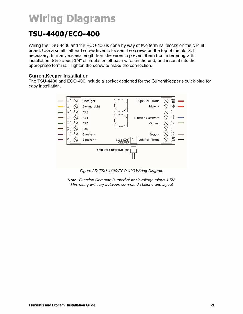
TSU-4400/ECO-400 Wiring the TSU-4400 and the ECO-400 is done by way of two terminal blocks on the circuit board. Use a small flathead screwdriver to loosen the screws on the top of the block. If necessary, trim any excess length from the wires to prevent them from interfering with installation. Strip about 1/4" of insulation off each wire, tin the end, and insert it into the appropriate terminal. Tighten the screw to make the connection.
CurrentKeeper Installation The TSU-4400 and ECO-400 include a socket designed for the CurrentKeeper’s quick-plug for easy installation.
Figure 25: TSU-4400/ECO-400 Wiring Diagram
Note: Function Common is rated at track voltage minus 1.5V.
This rating will vary between command stations and layout

Tsunami2 and Econami Installation Guide 22